high frequency&efficiency series mode … distributed grid tied micro inverter of the 1000w...
TRANSCRIPT
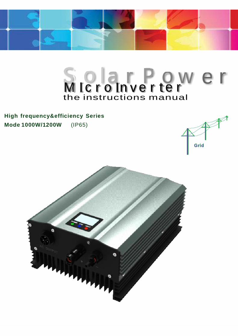
Grid
High frequency&efficiency SeriesMode 1000W/1200W (IP65)
http://www.new-pv.comhttp://www.new-pv.com
o la r P o w e rSthe instructions manualM I c r o In v e r te r
1
1 4. Applicability -----------------------------------------------------3
3 5. LCD Display --------- -----------------------------------------6
1.Specifications
1 1. Product Introduction------------------------------------------------2
1 3 Application. ------------------------------------------------------3
1.5 Packing inspection--------------------------------------- -------32.Safety instruction and Use Practice
2 1 Safety instruction. --------------------------------------------- --32 2 Use practice. ------------------------------------------------ ----33.Introductions to3 1 Introductions to the products. ----------------------------------- ---4.3 2 Products specificity ------------------------------------------ --4
----------------------------------------------53 3 Circuit organization.
3 4 LED pilot lamp. --------------------------------------------------5
3 6 Operation mode for grid connected inver. - - --------------------------74.fault treatment
5.Installation
5 1 Installation Sites. -------------------------------------------------85 2 Installation for Inverter. --------------------------------------- ---9
.6 Electrical connections and commissioning
6 1 Request for cable connecting. ------------------------------ ------106 2 Steps for Electrical connection. ---------------------------- -------106 3 AC terminal connection. ------------------------------------- ----116 4 DC terminal cennection. ------------------------------------- -----126 5Commissioning. ------------------------------------------------ --137.Appendices A
.8 Appendices B8 1Quality Assurance. ---------------------------------------------- -168 2Statement for Impunity and Copyright. ---------------- --------------- - ------17
Warranty Card -----------------------------------------------------18
Catalogue
7 1 Technical Parameter. ----------------------------------------------------------14
1 2. Contact Us -----------------------------------------------------2
Catalogue
2
1000W/1200W Brief introduction
:For more information to surf
The distributed grid tied micro inverter of The 1000W 1200W Series ittakes the innovative technology It has the same feature with centralizedinverter that can connect with several solar panels It is small and highefficiency like distributed inverter MPPT function is designed and that willbe showed on the LCD LED This Inverter Having multiple design patent ithas technical Features of high integration density about electrical designs i m p l e a n d e a s y c o n s t r u c t e d E a s y I n s t a l l a t i o n
The 000W 1200W is designed for outdoor used with IP65 PV Invertermore durable more efficiency
- / , .
. - . ,
, .
, , .
/ . , , .
,
1
1. - - ,
.
2 Contact us .If you have any questions about Single phase PV grid connected inverter
contact with us and we are pleased to answer the questions We will dobetter with your support.
1 1.
1. Attentions
Brief Introduction
3
.
1 3 Matters needing attention
1 4 Applicability
1 5 Checking the packaging
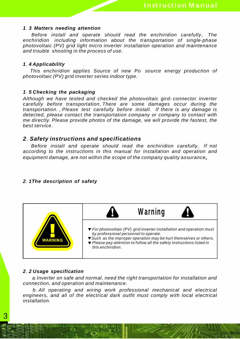
2 1The description of safety
2 2 Usage specification
.
,
.
.
- ,
., .
.
,
.
.
.
Before install and operate should read the enchiridion carefully Theenchiridion including information about the transportation of single-phasephotovoltaic (PV) grid light micro inverter installation operation and maintenanceand trouble shooting in the process of use.
This enchiridion applies Source of new Po source energy production ofphotovoltaic (PV) grid inverter series indoor type.
Although we have tested and checked the photovoltaic gird connector invertercarefully before transportation There are some damages occur during thetransportation Please test carefully before install If there is any damage isdetected, please contact the transportation company or company to contact withme directly. Please provide photos of the damage, we will provide the fastest, thebest service
Before install and operate should read the enchiridion carefully If notaccording to the instructions in this manual for installation and operation andequipment damage, are not within the scope of the company quality assurance
a.Inverter on safe and normal, need the right transportation for installation andconnection, and operation and maintenance.
b All operating and wiring work professional mechanical and electricalengineers, and all of the electrical dark outfit must comply with local electricalinstallation.
。
2 Safety instructions and specifications
For photovoltaic (PV grid inverter installation and operation must by professional personnel to operate.
Such as the improper operation may be hurt themselves or others. Please pay attention to follow all the safety instructions listed in this enchiridion
)
.
▼
▼▼
Warning
Instruction Manual
http://www.new-pv.com
4
c Before installation and wiring, please make sure this equipment is measuredwith voltmeter, dc side and ac side voltage to ensure on dc side and ac side voltageunder the operation. d According to the requirements of the document operation and installationinstructions, please strictly abide by all the warnings and safety informationprompt.
.
.
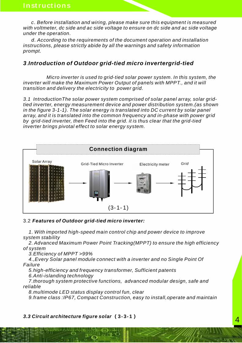
.3 Introduction of Outdoor grid-tied micro invertergrid-tied
Micro inverter is used to grid-tied solar power system. In this system, theinverter will make the Maximum Power Output of panels with MPPT., and it willtransition and delivery the electricity to power grid.
3.1 IntroductionThe solar power system comprised of solar panel array, solar grid-tied inverter, energy measurement device and power distribution system.(as shownin the figure 3-1-1). The solar energy is translated into DC current by solar panelarray, and it is translated into the common frequency and in-phase with power gridby grid-tied inverter, then Feed into the grid. it is thus clear that the grid-tiedinverter brings pivotal effect to solar energy system.
1. With imported high-speed main control chip and power device to improvesystem stability 2. Advanced Maximum Power Point Tracking(MPPT) to ensure the high efficiencyof system 3.Efficiency of MPPT >99% 4.,Every Solar panel module connect with a inverter and no Single Point OfFailure 5.high-efficiency and frequency transformer, Sufficient patents 6.Anti-islanding technology 7.thorough system protective functions, advanced modular design, safe andreliable 8.multimode LED status display control fun, clear 9.frame class :IP67, Compact Construction, easy to install,operate and maintain
3.2 Features of Outdoor grid-tied micro inverter:
3.3 Circuit architecture figure solar (3-3-1)
(3-1-1)
Connection diagram
GridGrid-Tied Micro InverterSolar Array
Electricity meter
Instructions
LED
5
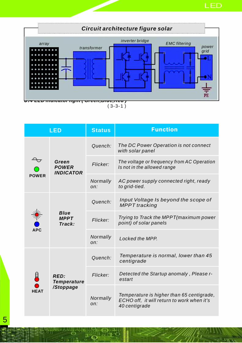
.3 4 LED indicator light ( Green,Blue,Red )(3-3-1)
Circuit architecture figure solar
LED
HEAT
APC
Quench:
Flicker:
Normallyon:
The DC Power Operation is not connectwith solar panel
GreenPOWERINDICATOR
The voltage or frequency from AC OperationIs not in the allowed range
AC power supply connected right, readyto grid-tied.
BlueMPPTTrack:
Input Voltage Is beyond the scope ofMPPT tracking
Trying to Track the MPPT(maximum powerpoint) of solar panels
Locked the MPP.
RED:Temperature/Stoppage
Temperature is normal, lower than 45centigrade
Detected the Startup anomaly , Please r-estart
Temperature is higher than 65 centigrade,ECHO off, it will return to work when it’s40 centigrade
arraytransformer
inverter bridgeEMC filtering
powergrid
POWER
Quench:
Flicker:
Normallyon:
Quench:
Flicker:
Normallyon:
Status
LCD
6
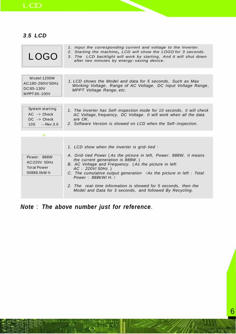
www spe pv com. - .3 5 LCD.
c
Model:1200WAC:180-260V 50Hz/DC:85-130VMPPT:65 100V-
Power: 888WAC:220V 50HzTotal Power00888 0kW h. ·
System startingAC Check ->DC Check ->10S Rev 3 0 -- . .
Note The above number just for reference : .
1 Input the corresponding current and voltage to the Inverter2 Starting the machine LCD will show the LOGO for 3 seconds3 The LCD backlight will work by starting And it will shut down
after two minutes by energy saving device
. .
. .
. , - .
,
1 LCD shows the Model and data for 5 seconds Such as MaxWorking Voltage Range of AC Voltage DC Input Voltage RangeMPPT Voltage Range etc
. , , , , , .
1 The Inverter has Self inspection mode for 10 seconds it will checkAC Voltage frequency DC Voltage It will work when all the dataare OK
2 Software Version is showed on LCD when the Self inspection
. - , , , . .. - .
1 LCD show when the inverter is grid tied
A Grid tied Power As the picture in left Power 888W it meansthe current generation is 888W
B AC Voltage and Frequency As the picture in leftAC 220V 50Hz
C The cumulative output generation As the picture in left TotalPower 888KW H
2 The real time information is showed for 5 seconds then theModel and Data for 3 seconds and followed By Recycling
. - :
. - ( , : , .). . ( :
: / .). ( :
: / .)
. - , , .
LOGO
7
3 The working mode of Grid tied Micro Inverter. -
- . -. - , - , ,
-
- - ( ) ( ) ,
, ( ) , ,
, , ,
,. , ,
, ,
, ,
,
, . . " "
6
【 】
【 】
【 】
【 】
【 】
1
2
3
4
LED/LCD
micro inverter system could monitor and autorun System could according tothe output power of pv modules array to determine whether to Grid Connected ornot System operation process includes power on grid connected standby modenormal shutdown and battery opc mode
Grid Connected
Grid connected power mode refers to the micro inverter converts photovoltaiccomponents of direct current dc to alternating current ac power grid in orderto ensure maximum power output the system adopts MPPT control methodcan guarantee the system in any sunshine time and temperature conditionsalways make pv array maximum power output state
tandby mode
Standby refers to the output voltage of solar module is below a certain value orthe grid parameters such as voltage frequency temperature is beyond the scopeof work permit grid inverter in the standby state
ormal shutdown
When the light intensity decrease the output power of solar module becameweak When power is low the machine will enter the standby mode when the pvmodule voltage lasts a minute under working voltage or the voltage of photovoltaicmodules is lower than the shutdown voltage output will shut down and go inshutdown state
5 Battery opc mode
The input dc side of this system could be connect with battery after detectionthe machines will get into opc mode automatically the power output is adjustedfor eighty percent of the total power to ensure that the machine could prolongedWork under the grid
When the fault indicating lamp light the micro inverter will stop automaticallyThe handling method please refer to section 3 4 lamp
4 Malfunction and processing.
Fault Handling
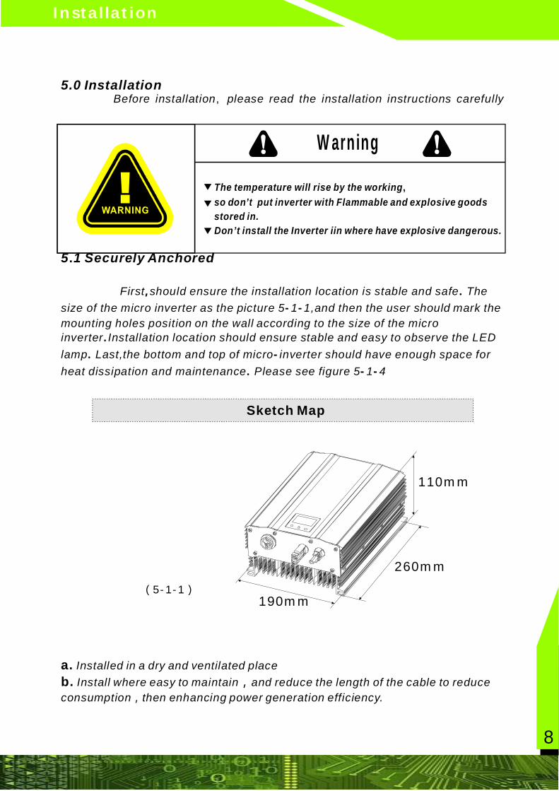
The temperature will rise by the workingso don’t put inverter with Flammable and explosive goodsstored in.Don’t install the Inverter iin where have explosive dangerous.
,
Warning
▼
▼
▼
Installation
8
5.0
5 1 Securely Anchored.
a.b.
Installed in a dry and ventilated placeInstall where easy to maintain and reduce the length of the cable to reduce
consumption then enhancing power generation efficiency.,
,
InstallationBefore installation please read the installation instructions carefully
First should ensure the installation location is stable and safe Thesize of the micro inverter as the picture 5 1 1,and then the user should mark themounting holes position on the wall according to the size of the microinverter Installation location should ensure stable and easy to observe the LEDlamp Last,the bottom and top of micro inverter should have enough space forheat dissipation and maintenance Please see figure 5 1 4
,
, . - -
.. - . - -
Sketch Map
(5-1-1)
110mm
260mm
190mm
Installation
9
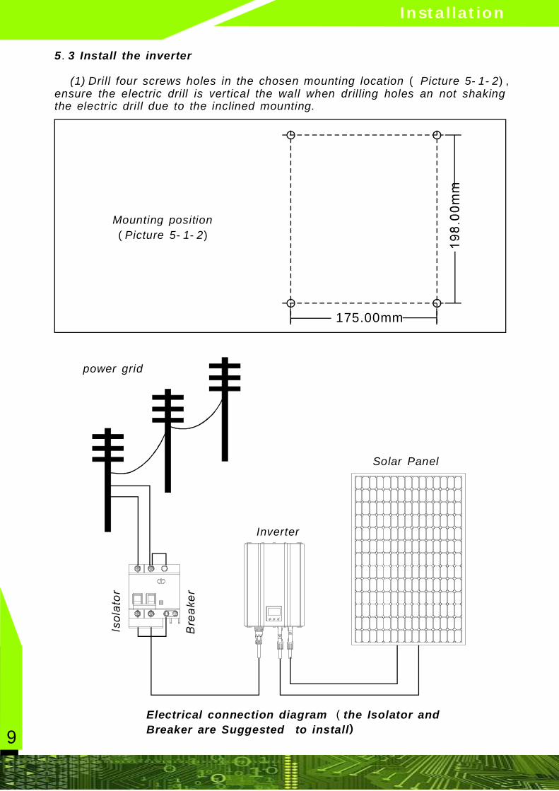
www spe pv com. - .5 3 Install the inverter.
( - - ), (1) Drill four screws holes in the chosen mounting location Picture 5 1 2ensure the electric drill is vertical the wall when drilling holes an not shakingthe electric drill due to the inclined mounting.
Mounting positionPicture 5 1 2 ( - - )
175.00mm
power grid
Solar Panel
Inverter
Electrical connection diagram the Isolator andBreaker are Suggested to install
()
Electrical Connection
10
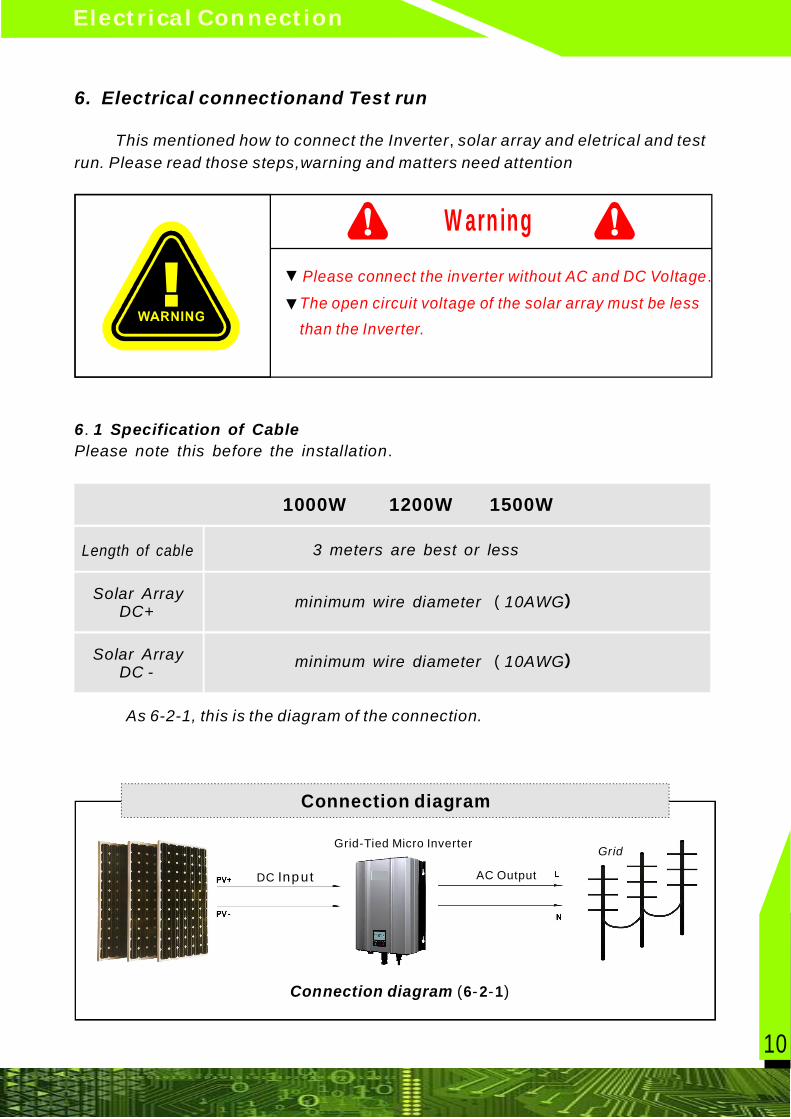
6. Electrical connectionand Test run
This mentioned how to connect the Inverter solar array and eletrical and testrun. Please read those steps,warning and matters need attention
As 6-2-1, this is the diagram of the connection.
,
6.2 connection step
6 1 Specification of Cable.
.Please note this before the installation
1200W
Solar Array DC+
1000W 1500W
Please connect the inverter without AC and DC Voltage
The open circuit voltage of the solar array must be lessthan the Inverter.
.
Warning
▼
▼
Connection diagram
Connection diagram ( - - )6 2 1
Grid-Tied Micro Inverter
DC Input AC Output
Grid
Length of cable 3 meters are best or less
Solar Array DC -
minimum wire diameter 10AWG( )
minimum wire diameter 10AWG( )
11
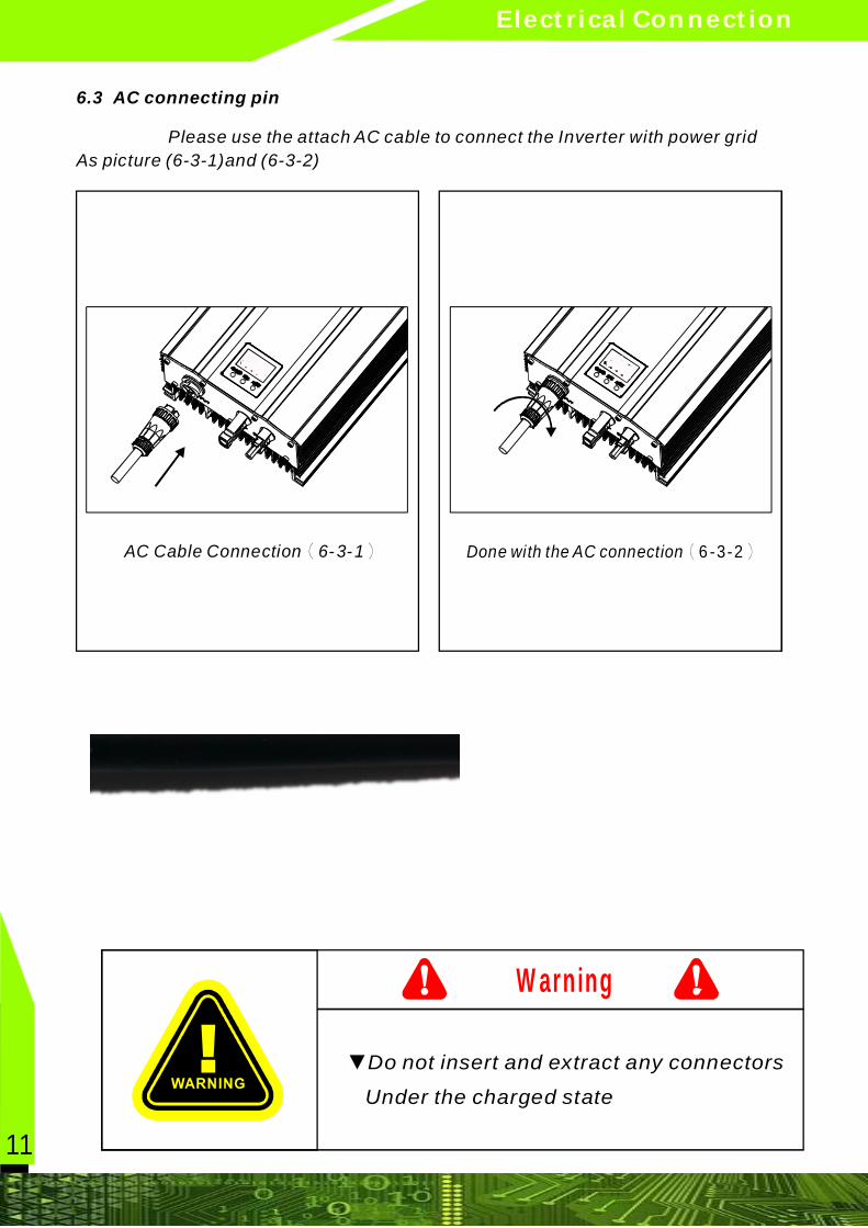
6.3 AC connecting pin
Please use the attach AC cable to connect the Inverter with power gridAs picture (6-3-1)and (6-3-2)
AC Cable Connection( - - )6 3 1 (6-3-2)Done with the AC connection
Electrical Connection
▼Do not insert and extract any connectors
Under the charged state
Warning
12
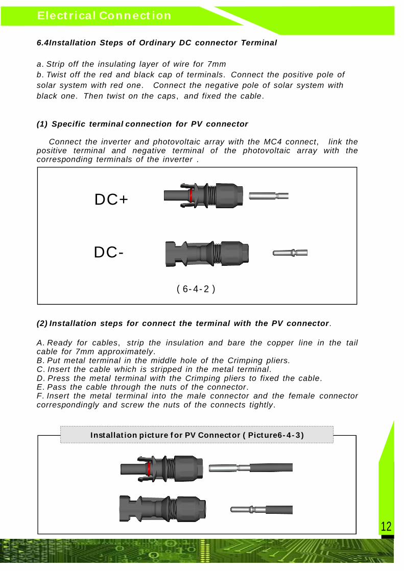
Electrical Connectionwww spe pv com. - .6.4Installation Steps of Ordinary DC connector Terminal
.
. .
.
. , .
a Strip off the insulating layer of wire for 7mmb Twist off the red and black cap of terminals Connect the positive pole ofsolar system with red one Connect the negative pole of solar system withblack one Then twist on the caps and fixed the cable
(1) Specific terminal connection for PV connector
(2) Installation steps for connect the terminal with the PV connector
,
.
.
. , .
.
. .
. .
. .
. .
Connect the inverter and photovoltaic array with the MC4 connect link thepositive terminal and negative terminal of the photovoltaic array with thecorresponding terminals of the inverter
A Ready for cables strip the insulation and bare the copper line in the tailcable for 7mm approximatelyB Put metal terminal in the middle hole of the Crimping pliers.C Insert the cable which is stripped in the metal terminalD Press the metal terminal with the Crimping pliers to fixed the cableE Pass the cable through the nuts of the connectorF Insert the metal terminal into the male connector and the female connectorcorrespondingly and screw the nuts of the connects tightly
(6-4- )2
DC+
DC-
Installation picture or V onnector icture6 ( - - )f P C P 4 3
13
(6-4- )4
( ) .
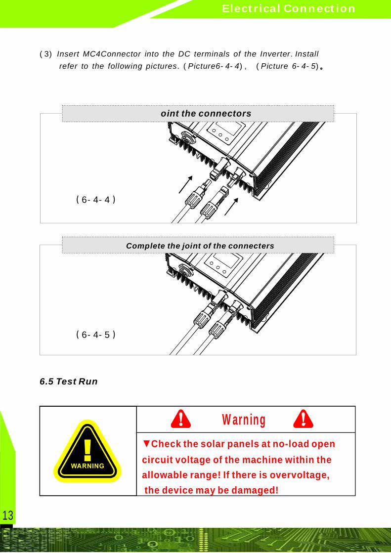
. ( - - ), ( - - )
3 Insert MC4Connector into the DC terminals of the Inverter Installrefer to the following pictures Picture6 4 4 Picture 6 4 5 。
(6-4- )5
▼Check the solar panels at no-load opencircuit voltage of the machine within theallowable range! If there is overvoltage, the device may be damaged!
Warning
6.5 Test Run
oint the connectors
Complete the joint of the connecters
Electrical Connection
14
1000W
1000
9
180-260 or 90-140
220 or 120
50/60
48-52/58-62
1200W
1200
6
After connected all the machines,Follow those steps to start the MrcroInverter :
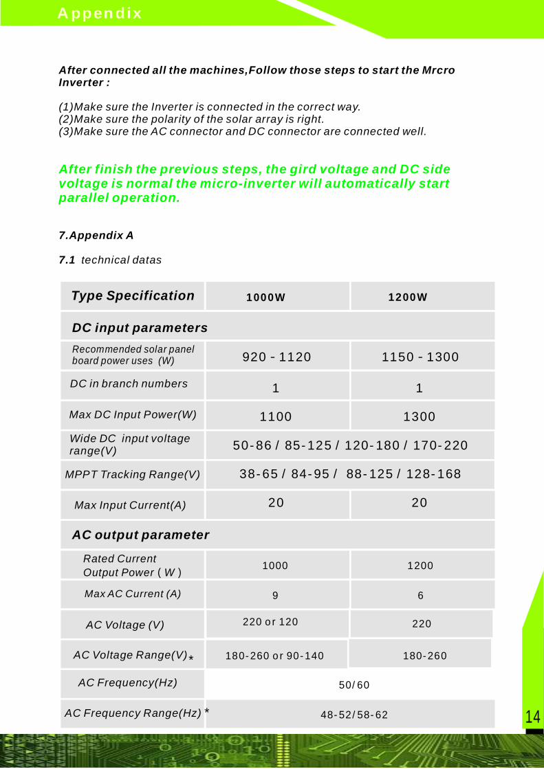
7.Appendix A
7.1
(1)Make sure the Inverter is connected in the correct way.(2)Make sure the polarity of the solar array is right.(3)Make sure the AC connector and DC connector are connected well.
technical datas
After finish the previous steps, the gird voltage and DC sidevoltage is normal the micro-inverter will automatically startparallel operation.
DC input parametersRecommended solar panelboard power uses (W)
DC in branch numbers
Max DC Input Power(W)
MPPT Tracking Range(V)
Wide DC input voltagerange(V)
Max Input Current(A)
AC output parameter
Max AC Current (A)
AC Voltage (V)
AC Voltage Range(V)
AC Frequency(Hz)
AC Frequency Range(Hz) *
Rated CurrentOutput Power W ( )
Type Specification
1
920 1120-
50-86 / 85-125 / 120-180 / 170-220
1100
38-65 / 84-95 / 88-125 / 128-168
20
1
1150 1300-
1300
20
*
Appendix
220
180-260

15
.
MPPT >99%
>0.99
<5%
VAC;FAC
1
<350mW
94%
>99%
>0.99
<5%
VAC;FAC
1
<350mW
94%
*
Size(length,width andheight,mm)
Weight(kg)
Work status indicator
Stand-by at nightpower consumption
Mechanical Data
Frequency
Biggest inverter effiency
Operating Ambienttemperature
Storage Temperature
Output Power Factor
Output Current total harmonicdistortion aberration tate THD
Anti-islanding ptotection
system parameter
25 years
Frame Class
Other Characteristics
Mate Component
Communication mode
Service Life(Year)
Wireless FSK
BIPV,CIGS Mono crystalline silicon solar cell,poly cell
25 years
Wireless FSK
Cooling Ways Natural cooling Natural cooling
LCD/LED LCD/LED
AC Output Connector *
- /+25 C 65 C° °
260*190*110
5 5.
I P 65
- /+25 C 65 C° °
260*190*110
5 5.
I P 65
- /+25 C 65 C° ° - /+25 C 65 C° °
Appendix
16
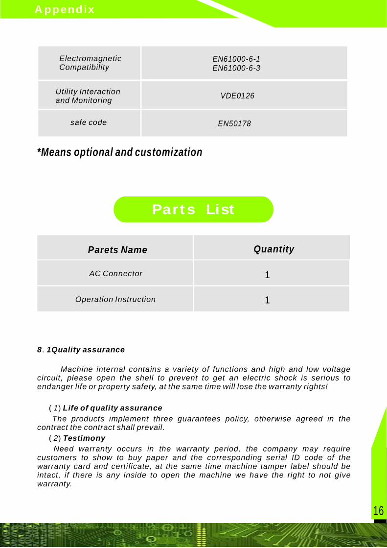
8 1Quality assurance
Life of quality assurance
Testimony
.
( )
( )
Machine internal contains a variety of functions and high and low voltagecircuit, please open the shell to prevent to get an electric shock is serious toendanger life or property safety, at the same time will lose the warranty rights!
1The products implement three guarantees policy, otherwise agreed in the
contract the contract shall prevail.2Need warranty occurs in the warranty period, the company may require
customers to show to buy paper and the corresponding serial ID code of thewarranty card and certificate, at the same time machine tamper label should beintact, if there is any inside to open the machine we have the right to not givewarranty.
Parts List
V1.2c EN61000-6-1EN61000-6-3
EN50178
VDE0126
*Means optional and customization
ElectromagneticCompatibility
safe code
Utility Interactionand Monitoring
Parets Name Quantity
1Operation Instruction
1AC Connector
Appendix
17
( ) :
. .. .
) .))))) (
)) ( , - ),
.
.
( ) ,
( )
( )
( )
3 Condition
a. Provide free reparation or replace the product service within warrantyperiod b. The unqualified products after replacement belongs to the manufacturer c Set aside a reasonable time for repairing of defective products
1 Transport damage by customer itself 2 Improper installation 3 Improper Modification 4 Improper Using 5 Running in severe environment beyond the instruction manual. 6 Damage in abnormal environment such as waterflood, debris flow ,snowstorm and so on 7 Damage caused by storage such as fall down water based liquidsirresistible force and so on by customer itself
The situation overstep the Quality warranty
8 2 Free of charge and copyright statement
1 If there are some changes about the product size and parameterWill be subject to the company information, without prior notice.
2 Electrical products should consist of professional and technicalpersonnel for installation and maintenance, and any other personnel tried tothis enchiridion for maintenance and repair, may cause serious damage, eventhere will be a dangerous property and life.
3 Copyright SOYO 2013 installation and operating enchiridion isprotected by international copyright laws.
4 Without the prior written permission of SOYO energy company in anyform, electronic or mechanical) translated copy distribution or transmissionof this installation and operation enchiridion of any content, includingcopying pictures recording or storing in any information storage andretrieval system.
Appendix
18
条码帖纸
Username
TelephoneNo.
Address
Zip
经销商代理商
地 址
联 系电 话
Name
Model
Date
Agency
Warranty CardFollowing Card
to manufacturerto customer
ModelName
Username
TelephoneNo.
Address
Zip
Date
Seal
Address
Agency
TelephoneNo.
Warranty Card