high exp. tech. & apps
DESCRIPTION
GUIDETRANSCRIPT
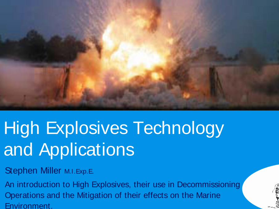
High Explosives Technology and ApplicationsStephen Miller M.I.Exp.E.
An introduction to High Explosives, their use in DecommissioningOperations and the Mitigation of their effects on the Marine Environment.
2
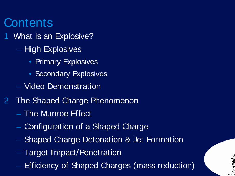
Contents1 What is an Explosive?
– High Explosives• Primary Explosives
• Secondary Explosives
– Video Demonstration
2 The Shaped Charge Phenomenon
– The Munroe Effect
– Configuration of a Shaped Charge
– Shaped Charge Detonation & Jet Formation
– Target Impact/Penetration
– Efficiency of Shaped Charges (mass reduction)
3
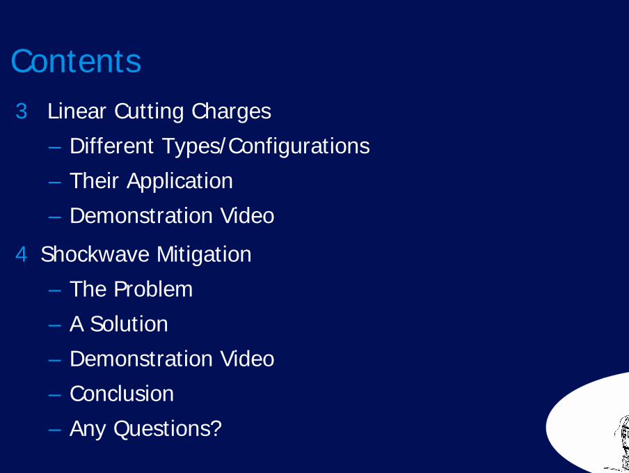
Contents3 Linear Cutting Charges
– Different Types/Configurations
– Their Application
– Demonstration Video
4 Shockwave Mitigation
– The Problem
– A Solution
– Demonstration Video
– Conclusion
– Any Questions?
What is an Explosive?Section 1
5
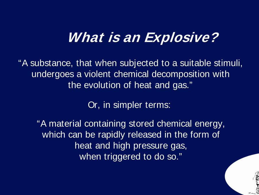
“A substance, that when subjected to a suitable stimuli, undergoes a violent chemical decomposition with
the evolution of heat and gas.”
Or, in simpler terms:
“A material containing stored chemical energy, which can be rapidly released in the form of
heat and high pressure gas, when triggered to do so.”
What is an Explosive?
6
Candle Plastic Explosive
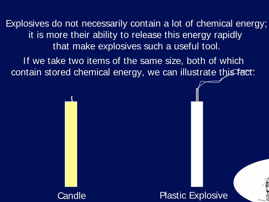
Explosives do not necessarily contain a lot of chemical energy;it is more their ability to release this energy rapidly
that make explosives such a useful tool.If we take two items of the same size, both of which
contain stored chemical energy, we can illustrate this fact:
7
Candle Plastic Explosive
1 x Heat1 x Gas
8 x Heat4 x Gas
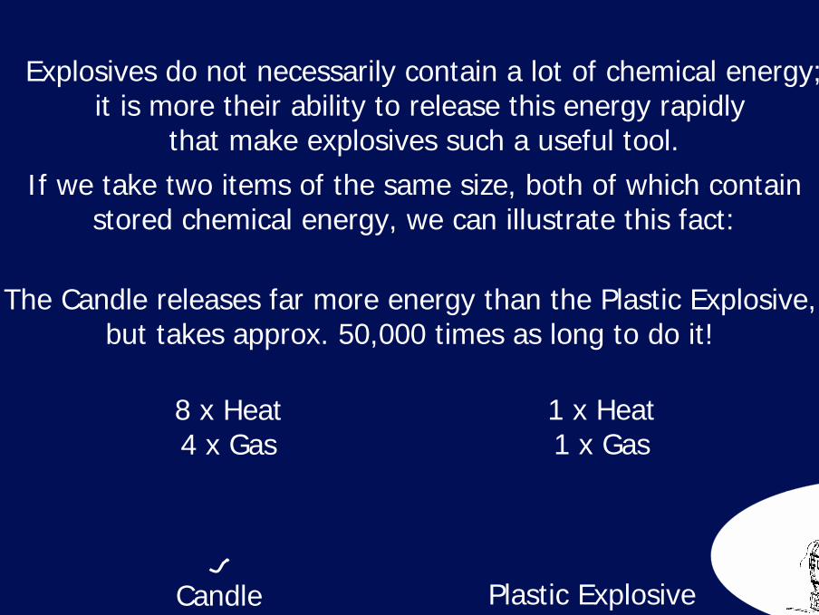
Explosives do not necessarily contain a lot of chemical energy;it is more their ability to release this energy rapidly
that make explosives such a useful tool.If we take two items of the same size, both of which contain
stored chemical energy, we can illustrate this fact:
The Candle releases far more energy than the Plastic Explosive,but takes approx. 50,000 times as long to do it!
8
High Explosives
The distinguishing feature of a High Explosive (HE), is thatit will Detonate under its normal conditions of use.
A Detonation is a specific type of explosion, where the chemical decomposition occurs so violently that it produces
a shock wave.

9
High ExplosivesThe shock wave passes through the HE at or faster than the speed of sound of the material (sound travels faster through
dense materials than it does through air).
As the shock wave meets unconsumed HE, the energy within theshock wave causes the explosive to Detonate, thus feeding and sustaining the shock wave.
As such, once a Detonation within an HE has been initiated,it will propagate through the entire charge
until all available explosive material has been consumed.
10
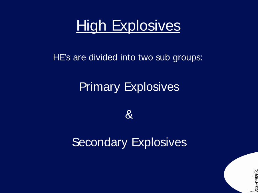
High Explosives
HE’s are divided into two sub groups:
Primary Explosives
&
Secondary Explosives

11
There are many examples of materials within thissub-set of High Explosives, including:
Lead Azide
Silver Azide
Lead Styphnate
PbN +
N
N
N
N
N
-
+ -
N +N N-Ag
Pb
2-
NO2
NO2
NO
O
O22+
H O2
Primary Explosives
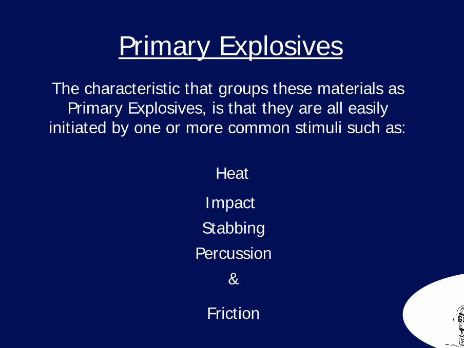
12
The characteristic that groups these materials as Primary Explosives, is that they are all easily
initiated by one or more common stimuli such as:
Heat
ImpactStabbing
Percussion
Friction
&
Primary Explosives
13
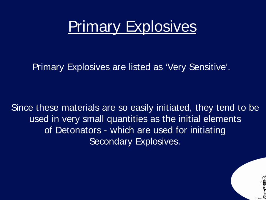
Since these materials are so easily initiated, they tend to beused in very small quantities as the initial elements
of Detonators - which are used for initiatingSecondary Explosives.
Primary Explosives
Primary Explosives are listed as ‘Very Sensitive’.
14
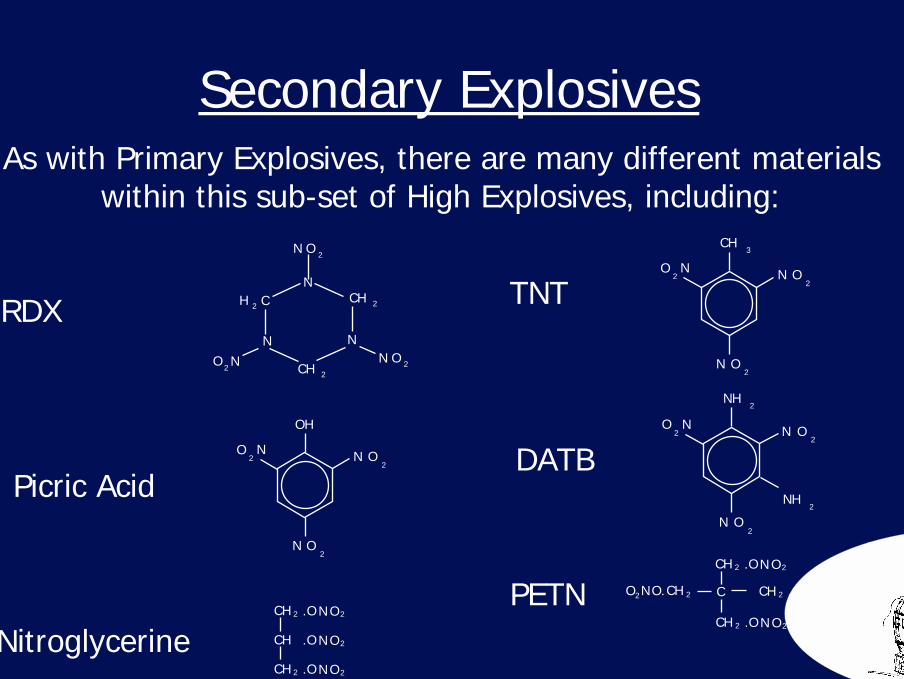
As with Primary Explosives, there are many different materialswithin this sub-set of High Explosives, including:
RDX TNT
Picric Acid
Nitroglycerine
DATB
PETN
N O2
N O2
N
NH
O2
2
NH2
N O2
N O2
N
CH
O2
3
N O2.OCH 2
N O2.OCH
N O2.OCH 2
N O2.OCH 2
N O2.OCH 2
C N O2.OCH 2NO2 O.CH 2
N O 2
N O 2
N CHO 22
NCH 2
NN
H 2 C
Secondary Explosives
N O2
N O2
N
OH
O2
15
The common characteristics that differentiates Secondary Explosivesfrom Primary substances is that in general, they are relatively difficult
to initiate and require a shock wave donor, such as a Detonator in order to establish a sustainable Detonation.
Since most Secondary Explosives are difficult to initiateby accident, they can be transported and usedreasonably safely. It is for this reason that
Secondary Explosives are by far the mostcommon explosive tool used.
Secondary Explosives
Secondary Explosives are generally listed as ‘Comparatively Insensitive’,although some fall into the range of ‘Sensitive materials’
16
Video Demonstrations
Hollywood ‘High Explosives’ & Real High Explosives
The Shaped Charge Phenomenon
Section 2
18The Shaped Charge Phenomenon
Shaped Charges are a means of focusing the stored chemical energythat is found in explosives to perform efficient and usefulwork by rapidly penetrating or cutting tough materials.
Military Shaped Charges are often referred to as HEAT rounds, whichhas lead to the common misconception that they, somehow melt
a hole through their target.
H.E.A.T. stands for High Explosive Anti-Tank and has nothing to dowith the temperature at which it penetrates.
In fact a copper jet formed by a shaped charge onlyreaches about 400 C. Jets are simply the linermetal behaving as a Newtonian viscous fluid.
They are not plasmas.
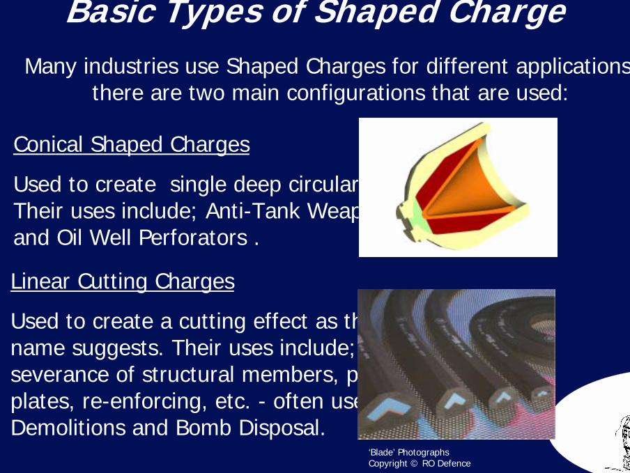
19Basic Types of Shaped Charge
Many industries use Shaped Charges for different applications,there are two main configurations that are used:
Conical Shaped Charges
Used to create single deep circular holes. Their uses include; Anti-Tank Weapons and Oil Well Perforators .
Linear Cutting Charges
Used to create a cutting effect as the name suggests. Their uses include; the severance of structural members, pipes, plates, re-enforcing, etc. - often used in Demolitions and Bomb Disposal.
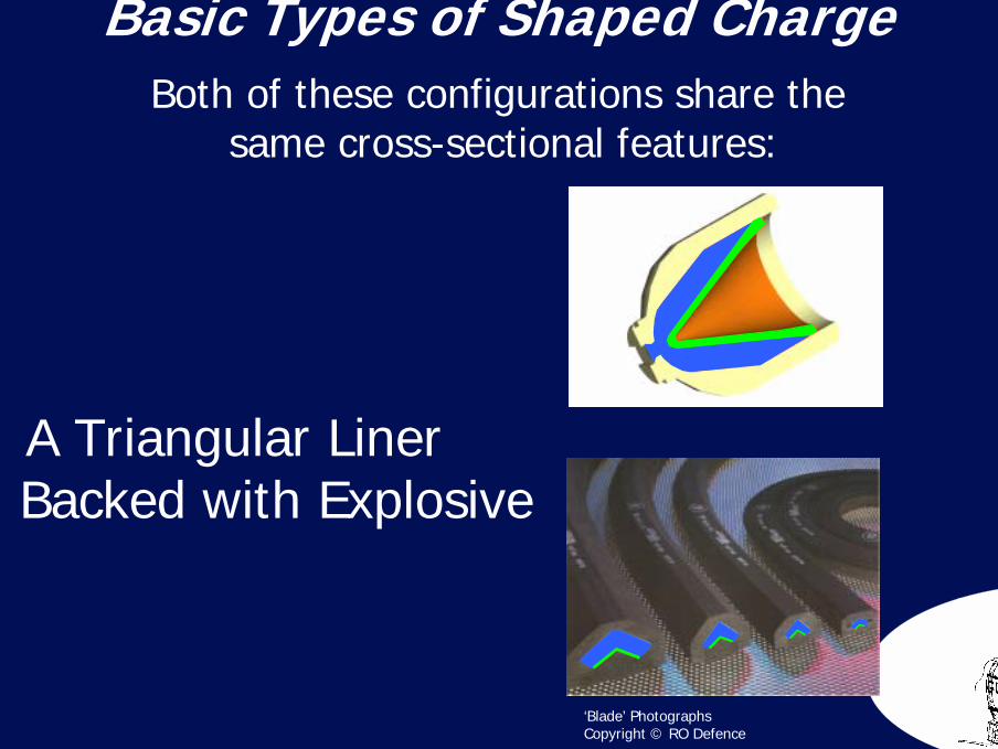
‘Blade’ Photographs Copyright © RO Defence
20
‘Blade’ Photographs Copyright © RO Defence
Basic Types of Shaped Charge Both of these configurations share the
same cross-sectional features:
A Triangular LinerBacked with Explosive
21
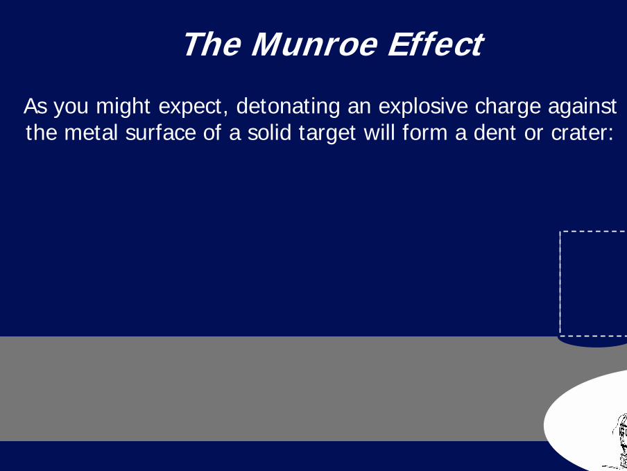
As you might expect, detonating an explosive charge againstthe metal surface of a solid target will form a dent or crater:
The Munroe Effect
22
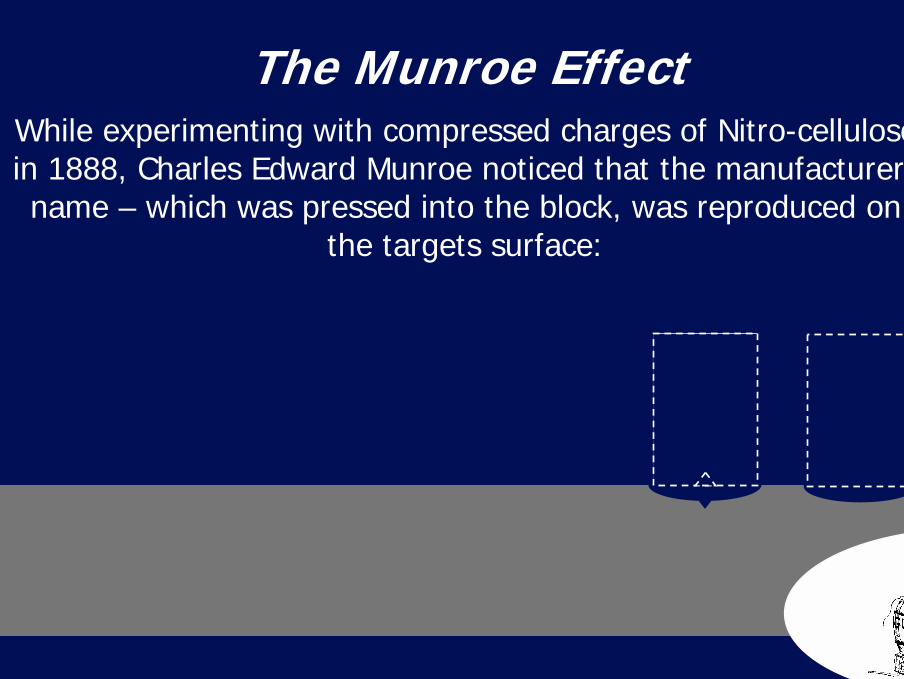
While experimenting with compressed charges of Nitro-cellulose in 1888, Charles Edward Munroe noticed that the manufacturers name – which was pressed into the block, was reproduced on
the targets surface:
The Munroe Effect
23
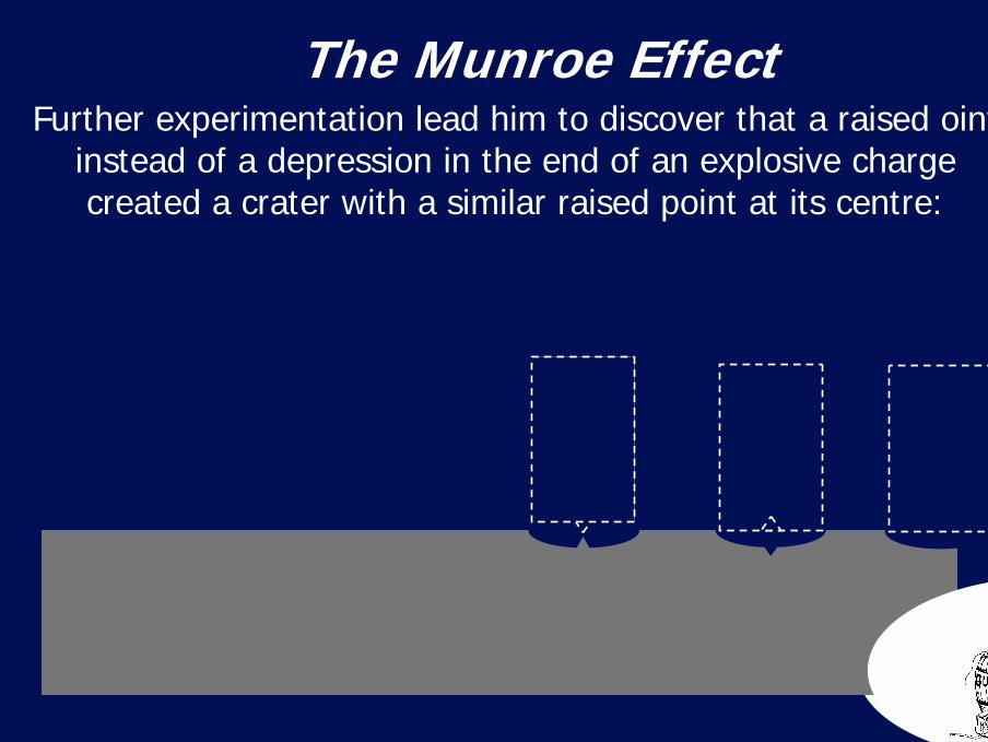
Further experimentation lead him to discover that a raised ointinstead of a depression in the end of an explosive charge created a crater with a similar raised point at its centre:
The Munroe Effect
24
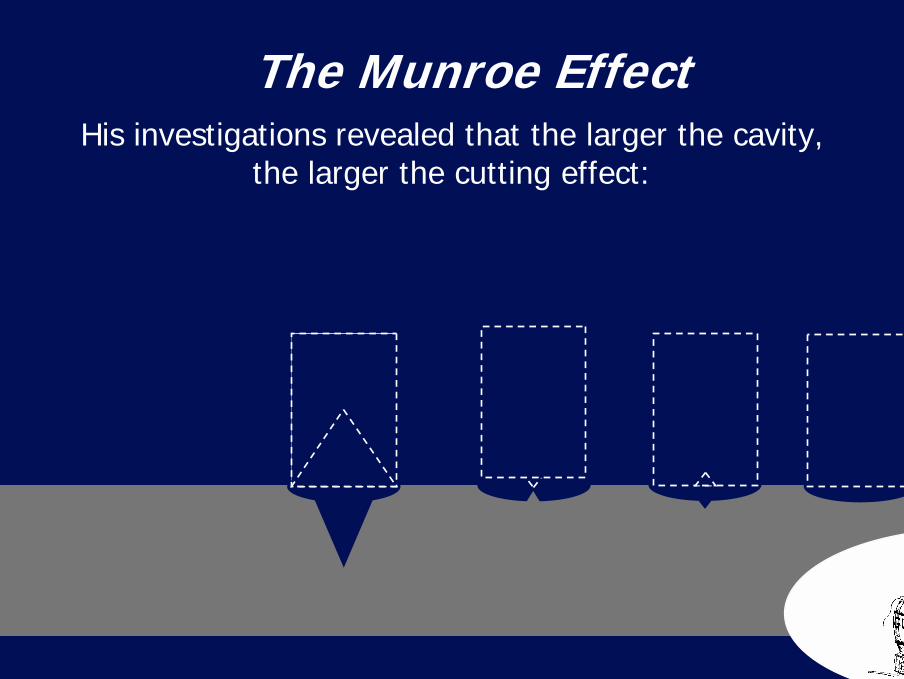
His investigations revealed that the larger the cavity,the larger the cutting effect:
The Munroe Effect
25
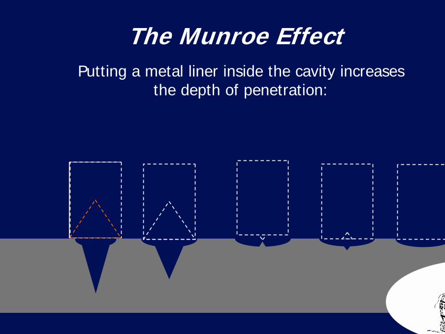
Putting a metal liner inside the cavity increasesthe depth of penetration:
The Munroe Effect
26
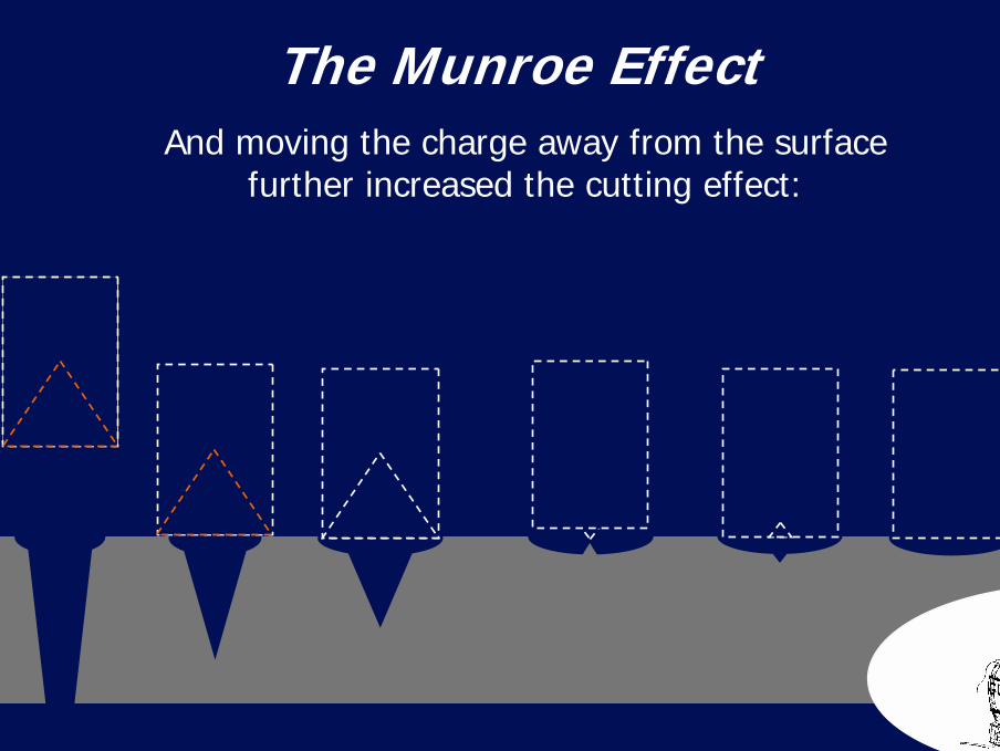
And moving the charge away from the surface further increased the cutting effect:
The Munroe Effect
27
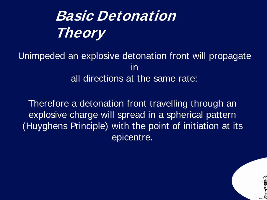
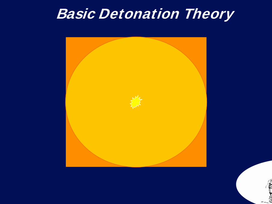
Unimpeded an explosive detonation front will propagate in
all directions at the same rate:
Therefore a detonation front travelling through an explosive charge will spread in a spherical pattern
(Huyghens Principle) with the point of initiation at its epicentre.
Basic Detonation Theory
28Basic Detonation Theory
29
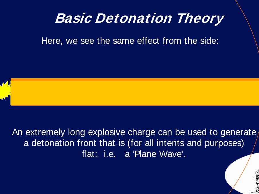
Basic Detonation TheoryHere, we see the same effect from the side:
An extremely long explosive charge can be used to generatea detonation front that is (for all intents and purposes)
flat: i.e. a ‘Plane Wave’.
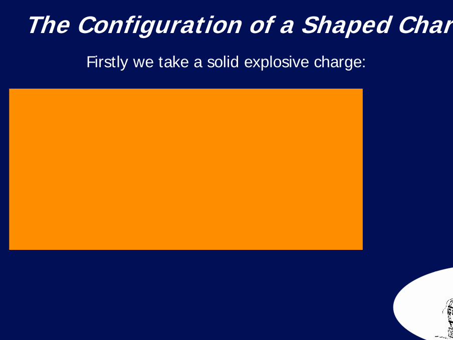
30The Configuration of a Shaped ChargeFirstly we take a solid explosive charge:
31
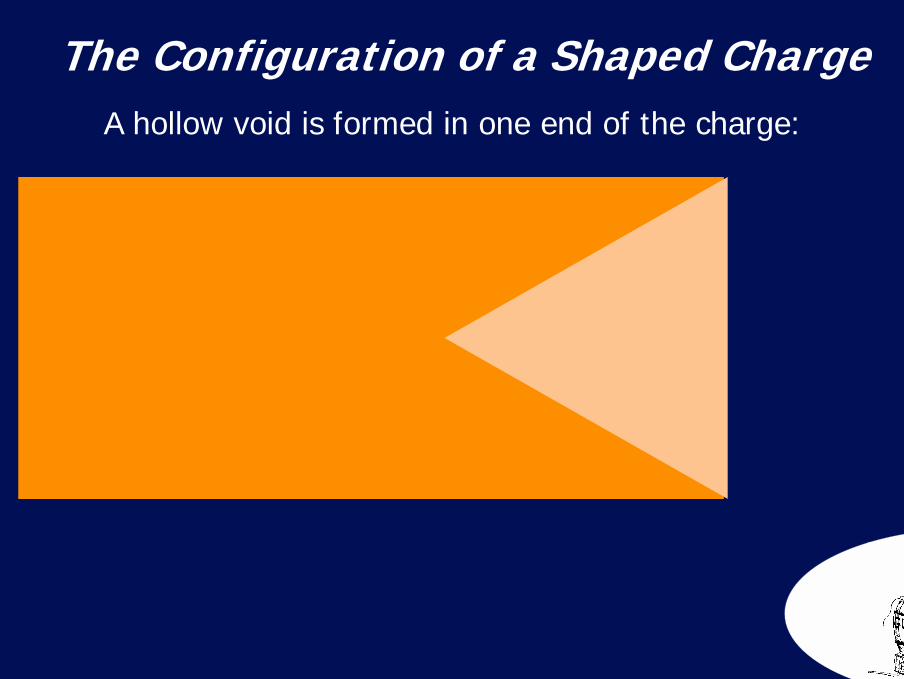
A hollow void is formed in one end of the charge:
The Configuration of a Shaped Charge
32
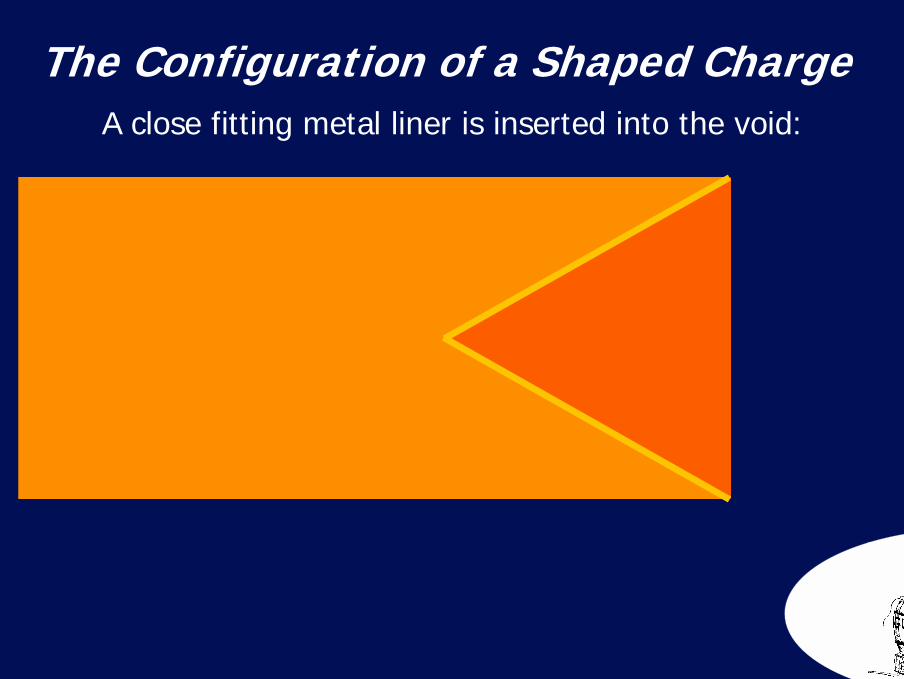
A close fitting metal liner is inserted into the void:
The Configuration of a Shaped Charge
33
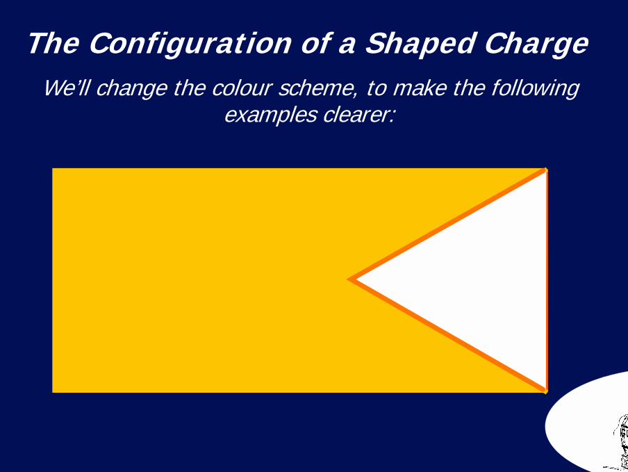
We’ll change the colour scheme, to make the following examples clearer:
The Configuration of a Shaped Charge
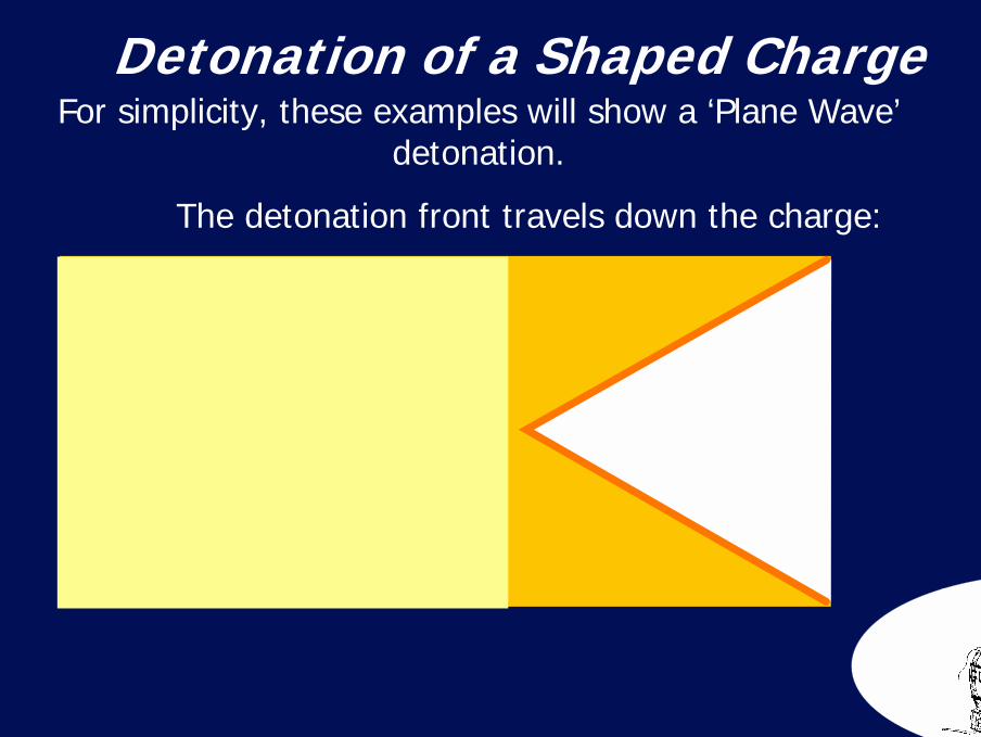
34Detonation of a Shaped ChargeFor simplicity, these examples will show a ‘Plane Wave’
detonation.
The detonation front travels down the charge:

35
Detonation of a Shaped ChargeThe detonation front meets the metal liner:

36
Detonation of a Shaped ChargeThe detonation front meets the metal liner:
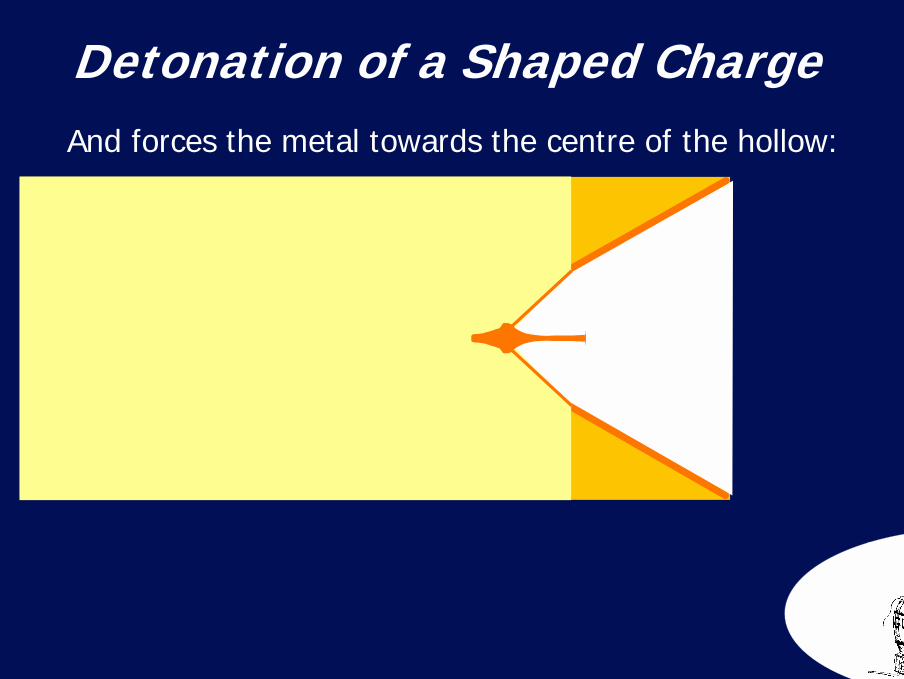
37Detonation of a Shaped ChargeAnd forces the metal towards the centre of the hollow:
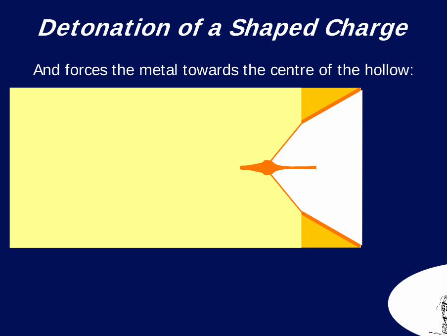
38Detonation of a Shaped ChargeAnd forces the metal towards the centre of the hollow:
39
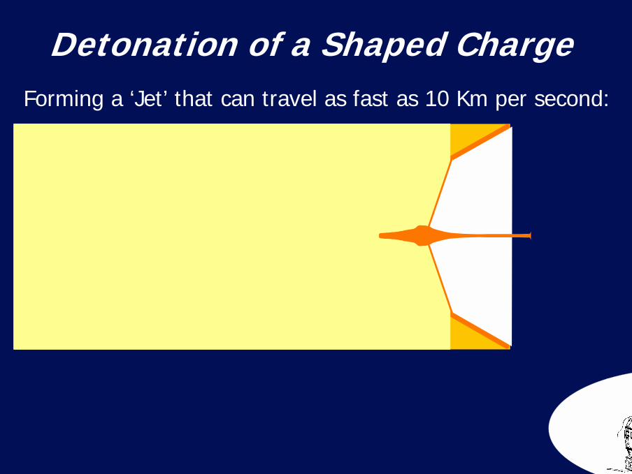
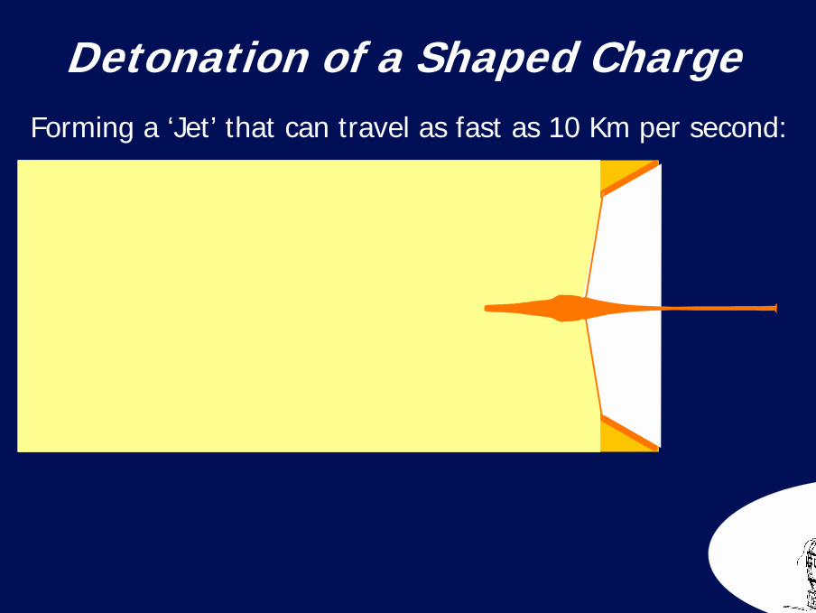
Detonation of a Shaped ChargeForming a ‘Jet’ that can travel as fast as 10 Km per second:
40
Detonation of a Shaped ChargeForming a ‘Jet’ that can travel as fast as 10 Km per second:
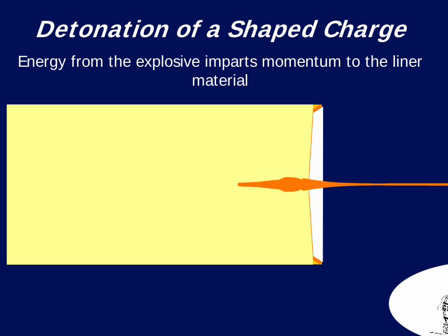
41Detonation of a Shaped ChargeEnergy from the explosive imparts momentum to the liner
material
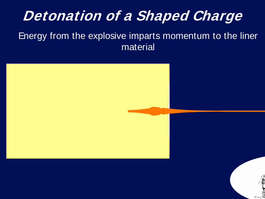
42Detonation of a Shaped ChargeEnergy from the explosive imparts momentum to the liner
material
43
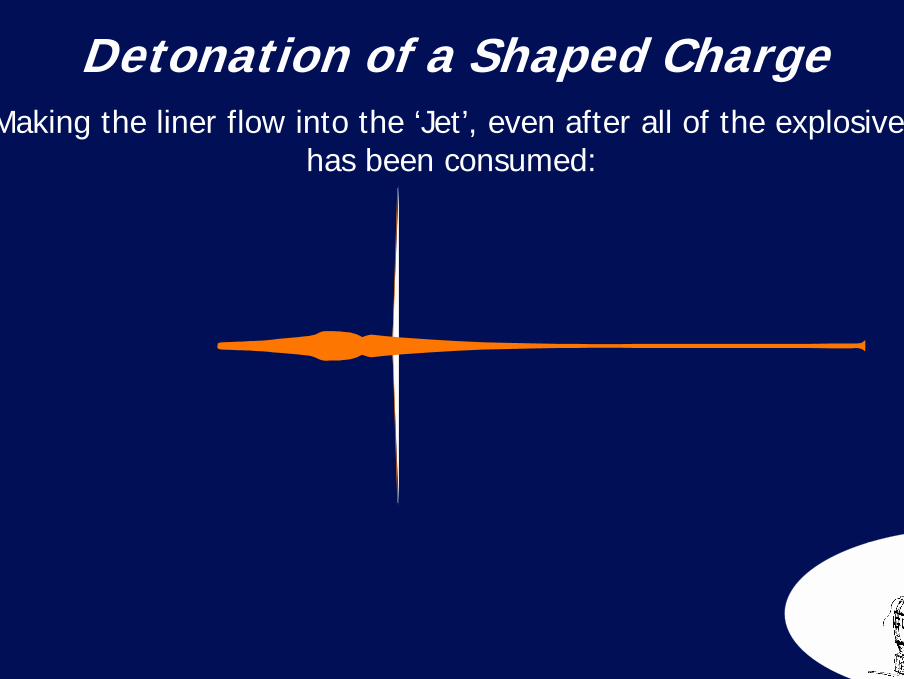
Making the liner flow into the ‘Jet’, even after all of the explosive has been consumed:
Detonation of a Shaped Charge
44
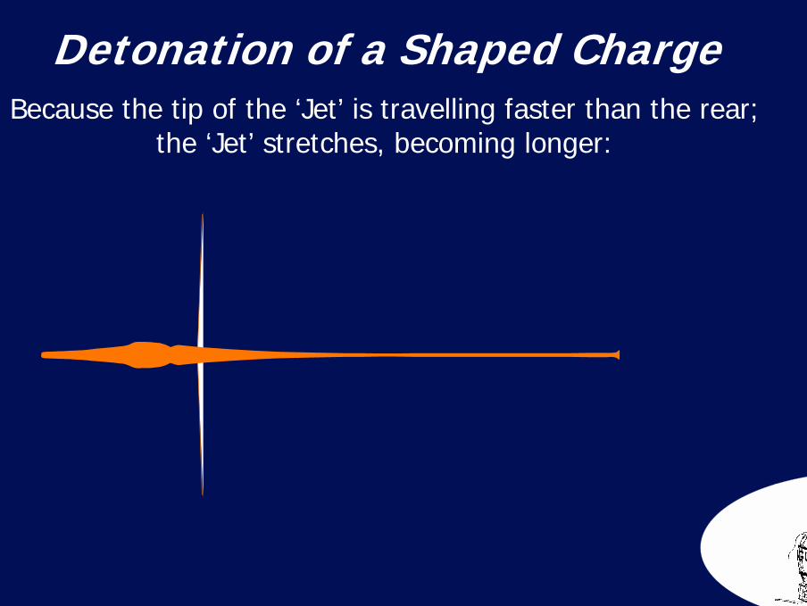
Because the tip of the ‘Jet’ is travelling faster than the rear;the ‘Jet’ stretches, becoming longer:
Detonation of a Shaped Charge

45
Shaped Charge Jet Formation
And longer:
46
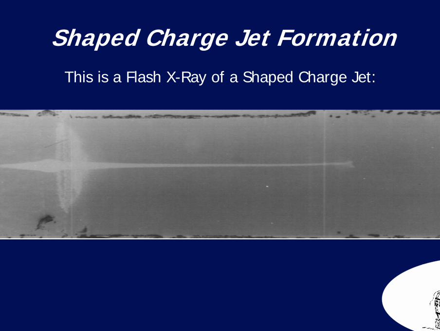
This is a Flash X-Ray of a Shaped Charge Jet:
Shaped Charge Jet Formation
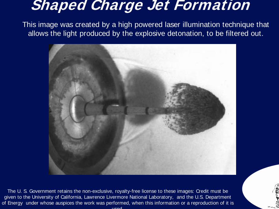
47Shaped Charge Jet Formation
This image was created by a high powered laser illumination technique thatallows the light produced by the explosive detonation, to be filtered out.
The U. S. Government retains the non-exclusive, royalty-free license to these images: Credit must be given to the University of California, Lawrence Livermore National Laboratory, and the U.S. Department
of Energy under whose auspices the work was performed, when this information or a reproduction of it is used.
48
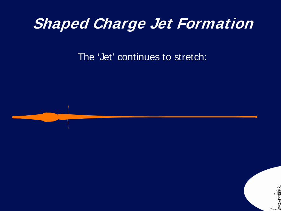
The ‘Jet’ continues to stretch:
Shaped Charge Jet Formation
49
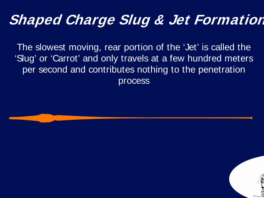
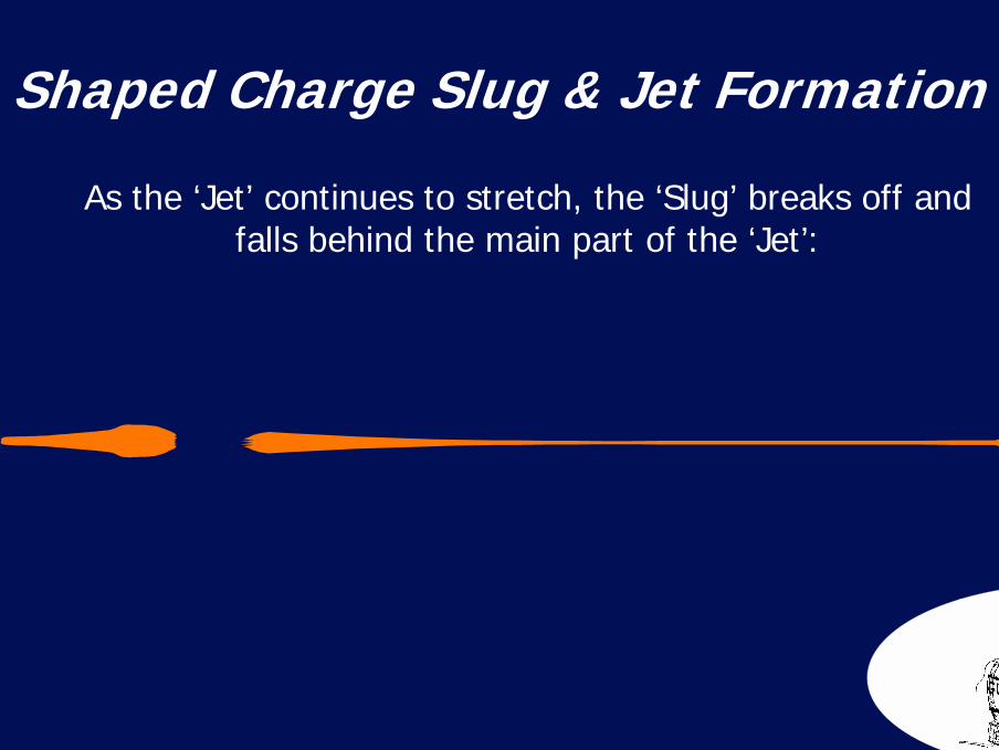
Shaped Charge Slug & Jet Formation
The slowest moving, rear portion of the ‘Jet’ is called the ‘Slug’ or ‘Carrot’ and only travels at a few hundred meters
per second and contributes nothing to the penetration process
50
Shaped Charge Slug & Jet Formation
As the ‘Jet’ continues to stretch, the ‘Slug’ breaks off and falls behind the main part of the ‘Jet’:
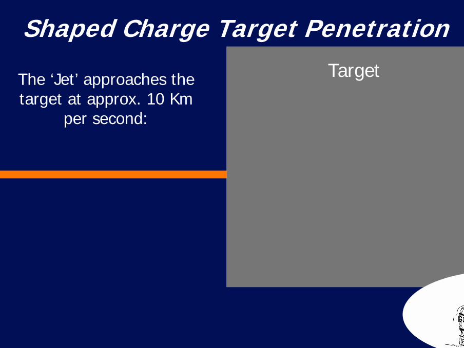
51Shaped Charge Target Penetration
The ‘Jet’ approaches the target at approx. 10 Km
per second:
Target
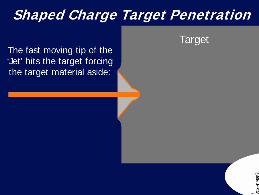
52Shaped Charge Target Penetration
The fast moving tip of the ‘Jet’ hits the target forcing the target material aside:
Target
53Shaped Charge Target Penetration
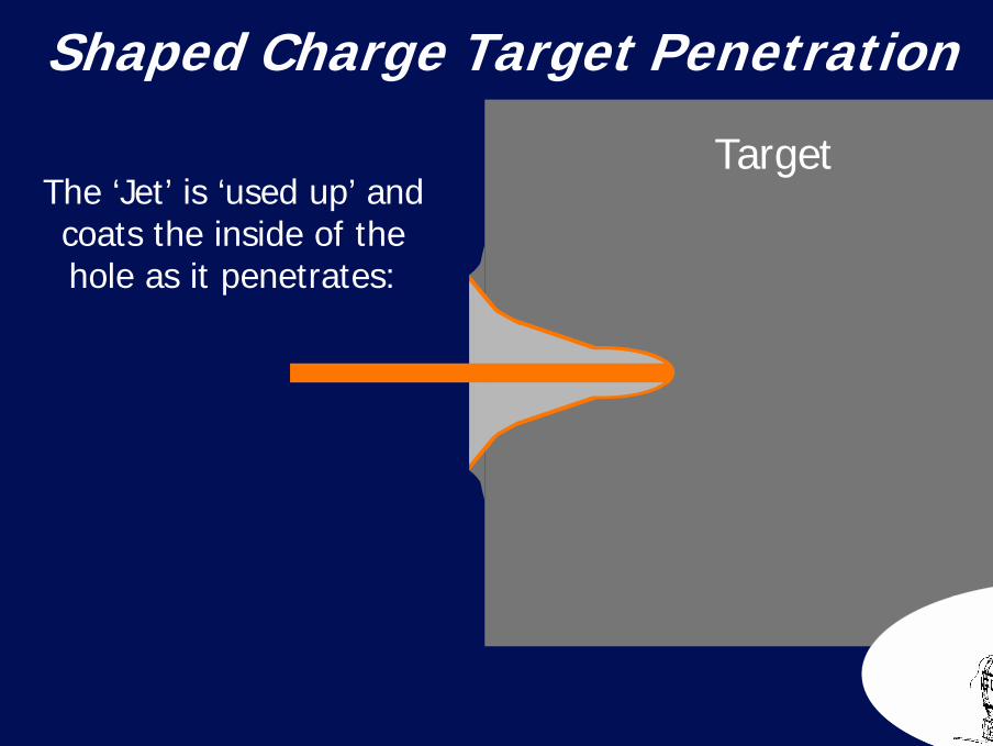
The ‘Jet’ is ‘used up’ and coats the inside of the hole as it penetrates:
Target

54Shaped Charge Target Penetration
The ‘Jet’ is ‘used up’ and coats the inside of the hole
as it penetrates:
Target
55Shaped Charge Target Penetration
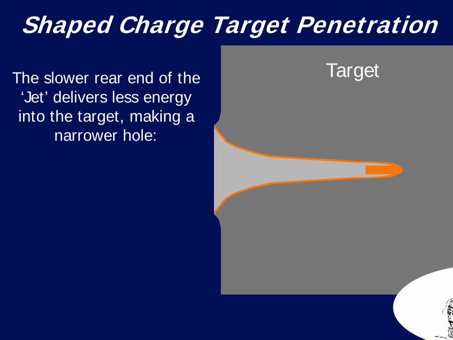
The slower rear end of the ‘Jet’ delivers less energy into the target, making a
narrower hole:
Target
56Shaped Charge Target Penetration
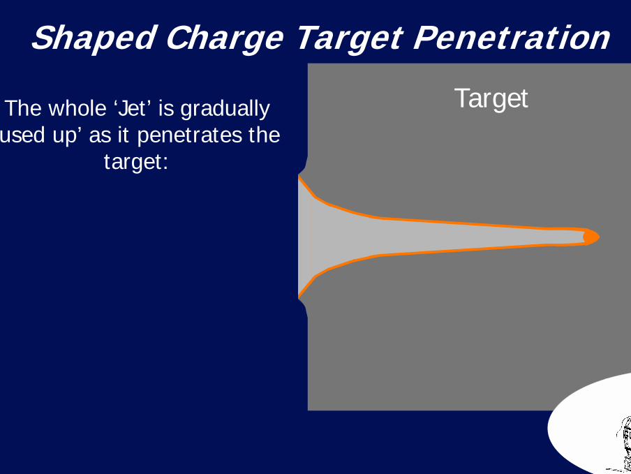
The whole ‘Jet’ is gradually‘used up’ as it penetrates the
target:
Target
57Shaped Charge Target Penetration
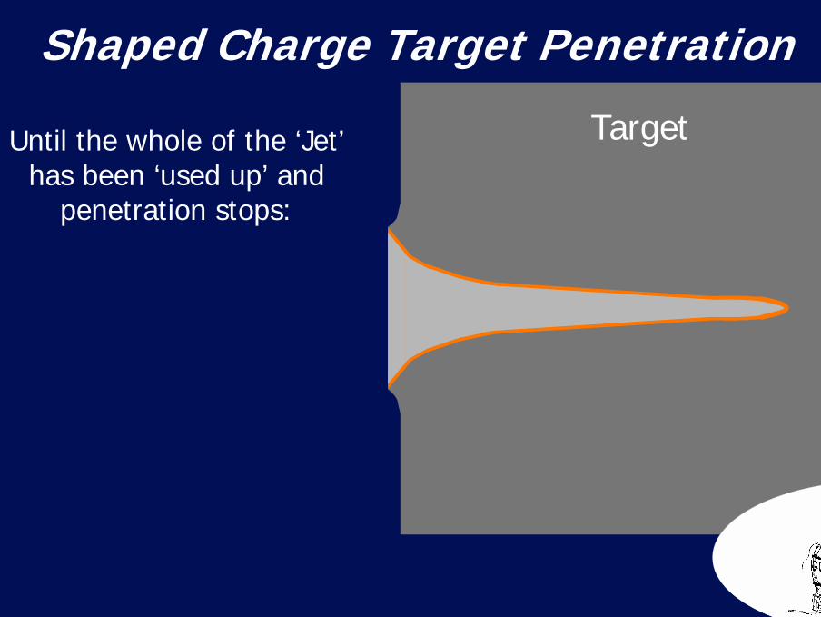
Until the whole of the ‘Jet’has been ‘used up’ and
penetration stops:
Target

58Shaped Charge Target PenetrationThis is a Flash X-Ray Showing A Jet Penetrating A Target
59
0mm 50mm 100mm 150mm 200mm
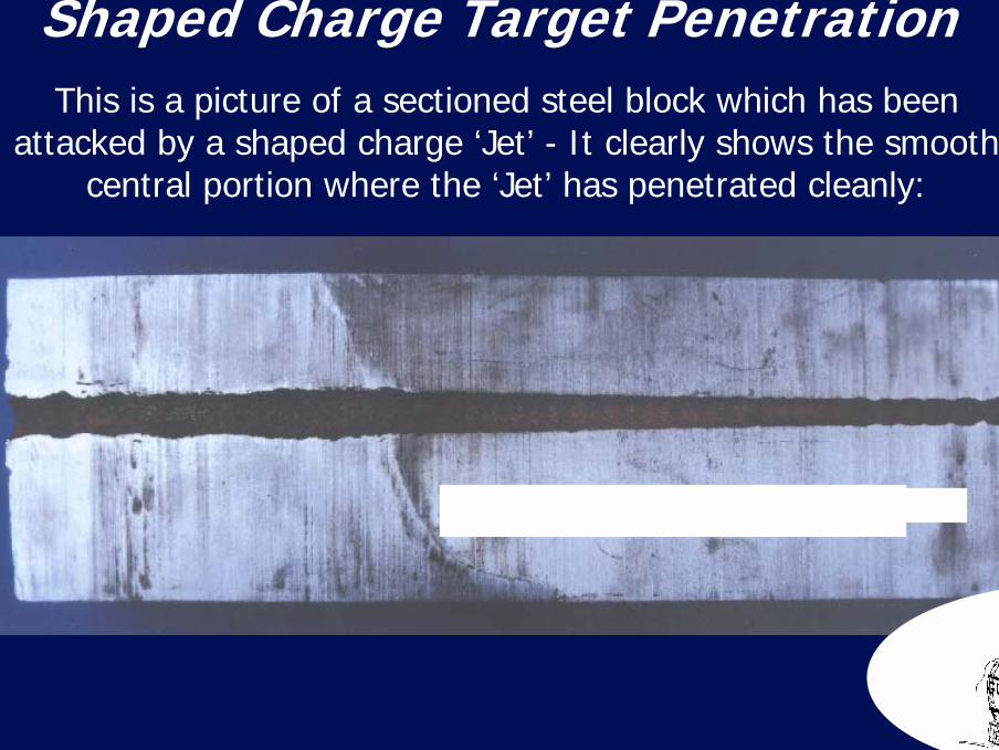
Shaped Charge Target PenetrationThis is a picture of a sectioned steel block which has been
attacked by a shaped charge ‘Jet’ - It clearly shows the smooth central portion where the ‘Jet’ has penetrated cleanly:
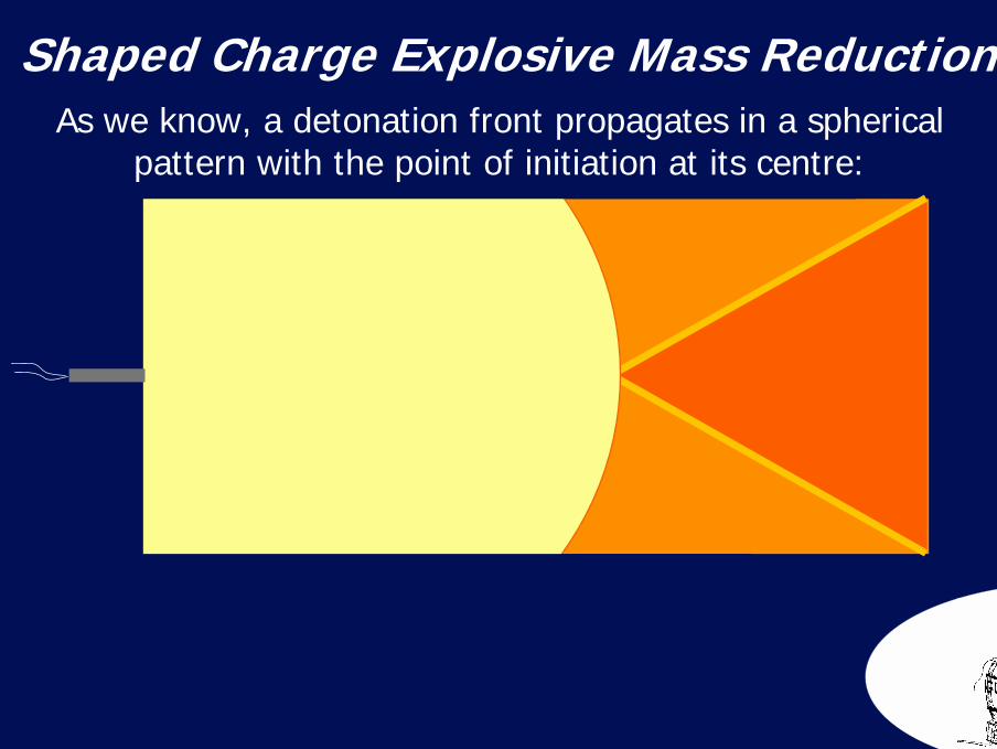
60Shaped Charge Explosive Mass ReductionAs we know, a detonation front propagates in a spherical
pattern with the point of initiation at its centre:
61
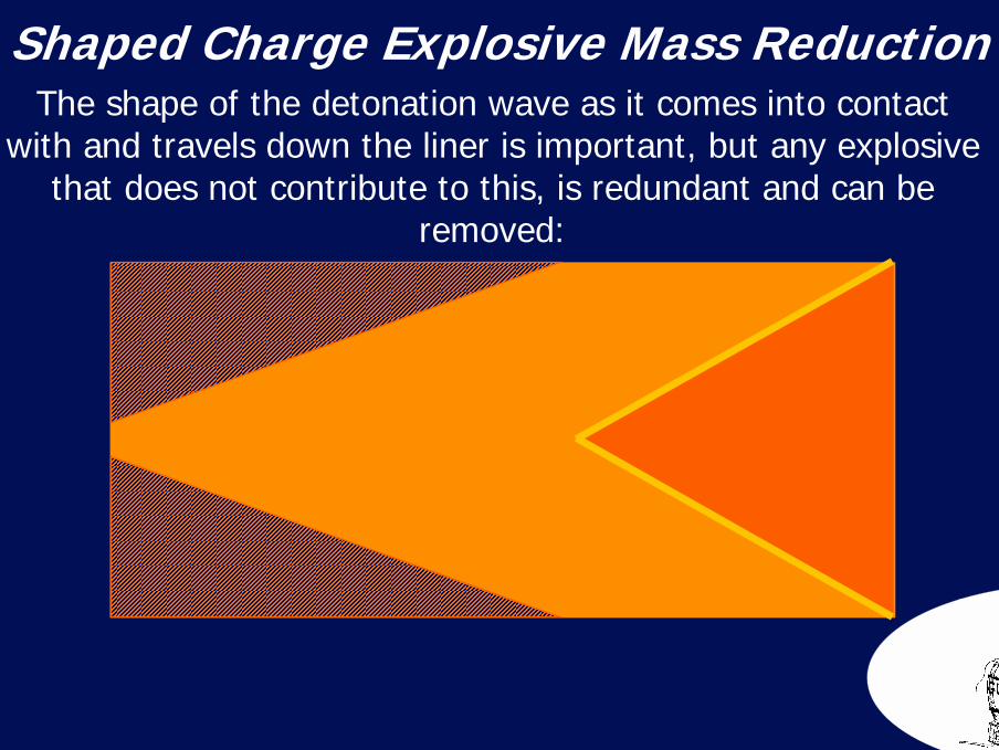
The shape of the detonation wave as it comes into contact with and travels down the liner is important, but any explosive
that does not contribute to this, is redundant and can be removed:
Shaped Charge Explosive Mass Reduction
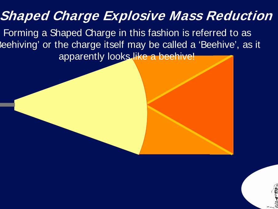
62Shaped Charge Explosive Mass ReductionForming a Shaped Charge in this fashion is referred to as
‘Beehiving’ or the charge itself may be called a ‘Beehive’, as it apparently looks like a beehive!
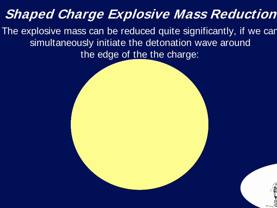
63Shaped Charge Explosive Mass ReductionThe explosive mass can be reduced quite significantly, if we can
simultaneously initiate the detonation wave aroundthe edge of the the charge:
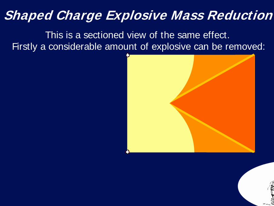
64Shaped Charge Explosive Mass ReductionThis is a sectioned view of the same effect.
Firstly a considerable amount of explosive can be removed:
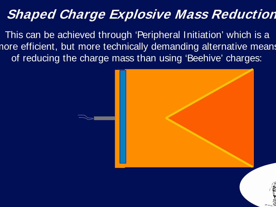
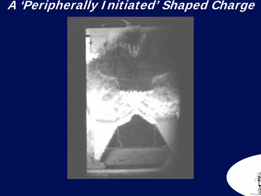
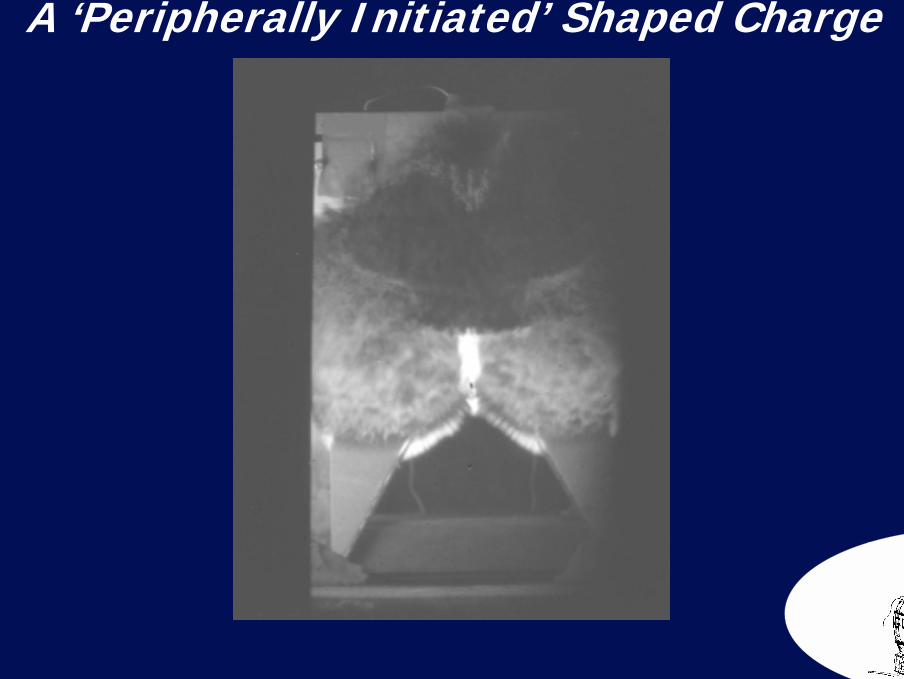
65Shaped Charge Explosive Mass ReductionThis can be achieved through ‘Peripheral Initiation’ which is a
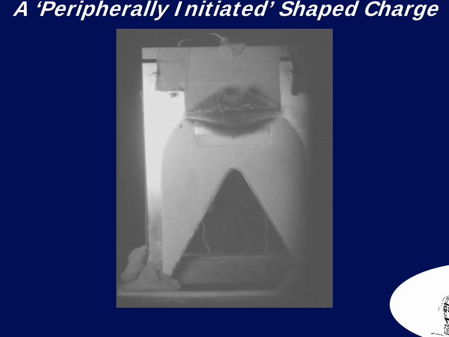
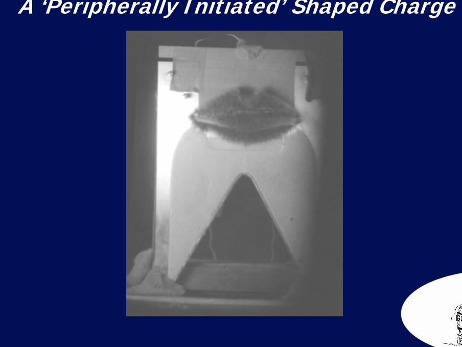
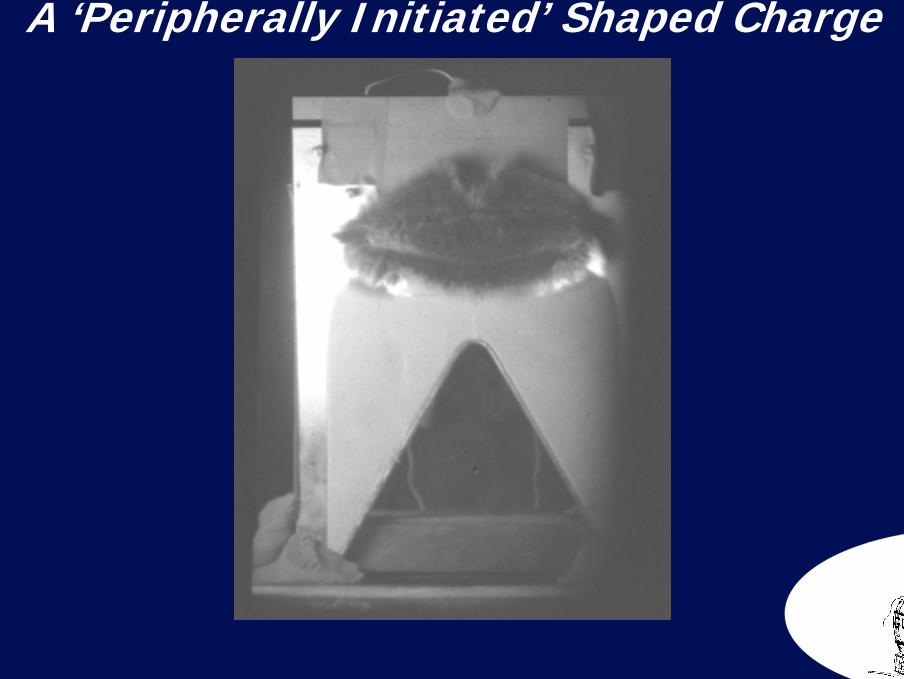
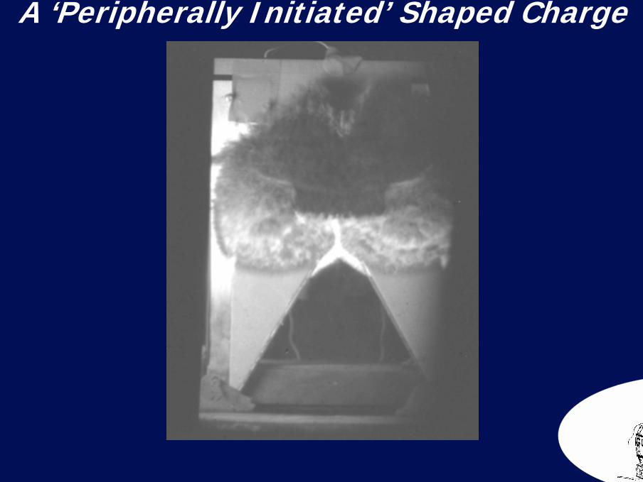
more efficient, but more technically demanding alternative meansof reducing the charge mass than using ‘Beehive’ charges:
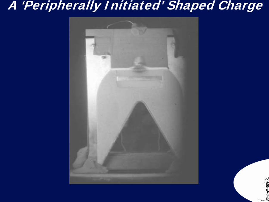
66A ‘Peripherally Initiated’ Shaped Charge
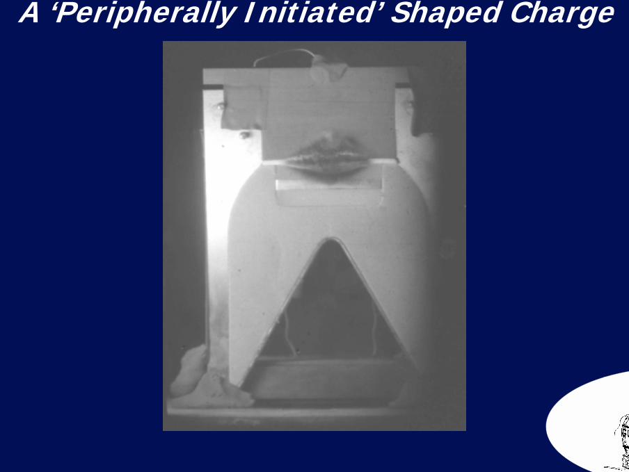
67A ‘Peripherally Initiated’ Shaped Charge
68A ‘Peripherally Initiated’ Shaped Charge
69A ‘Peripherally Initiated’ Shaped Charge
70A ‘Peripherally Initiated’ Shaped Charge

71A ‘Peripherally Initiated’ Shaped Charge
72A ‘Peripherally Initiated’ Shaped Charge
73A ‘Peripherally Initiated’ Shaped Charge
74A ‘Peripherally Initiated’ Shaped Charge
*
Linear Cutting Charges
Section 3
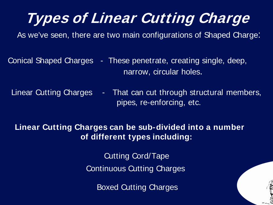
76Types of Linear Cutting Charge As we’ve seen, there are two main configurations of Shaped Charge:
Conical Shaped Charges - These penetrate, creating single, deep, narrow, circular holes.
Linear Cutting Charges - That can cut through structural members, pipes, re-enforcing, etc.
Linear Cutting Charges can be sub-divided into a numberof different types including:
Cutting Cord/Tape
Continuous Cutting Charges
Boxed Cutting Charges
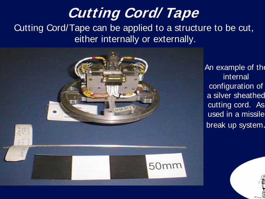
77Cutting Cord/Tape Cutting Cord/Tape can be applied to a structure to be cut,
either internally or externally.
An example of the internal
configuration of a silver sheathed cutting cord. As used in a missile break up system.
78
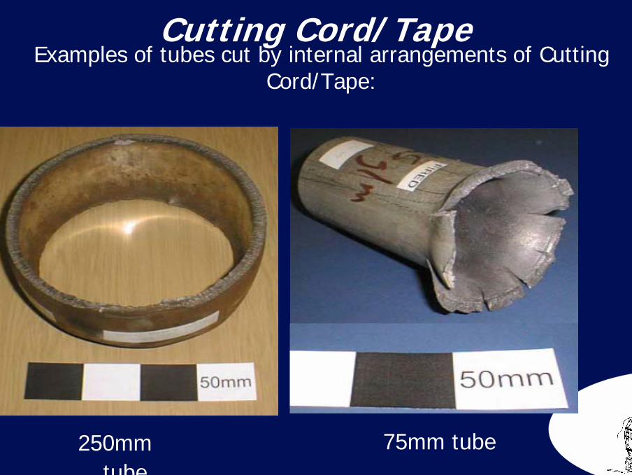
250mm tube
Cutting Cord/Tape Examples of tubes cut by internal arrangements of Cutting
Cord/Tape:
75mm tube
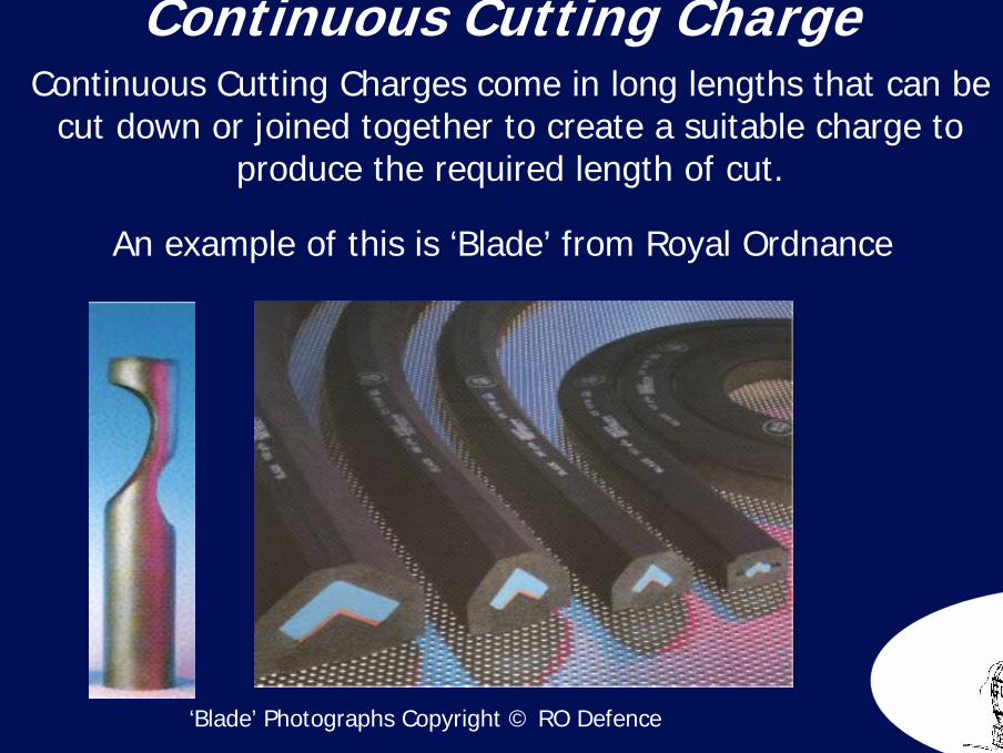
79Continuous Cutting Charge
Continuous Cutting Charges come in long lengths that can be cut down or joined together to create a suitable charge to
produce the required length of cut.
An example of this is ‘Blade’ from Royal Ordnance
‘Blade’ Photographs Copyright © RO Defence
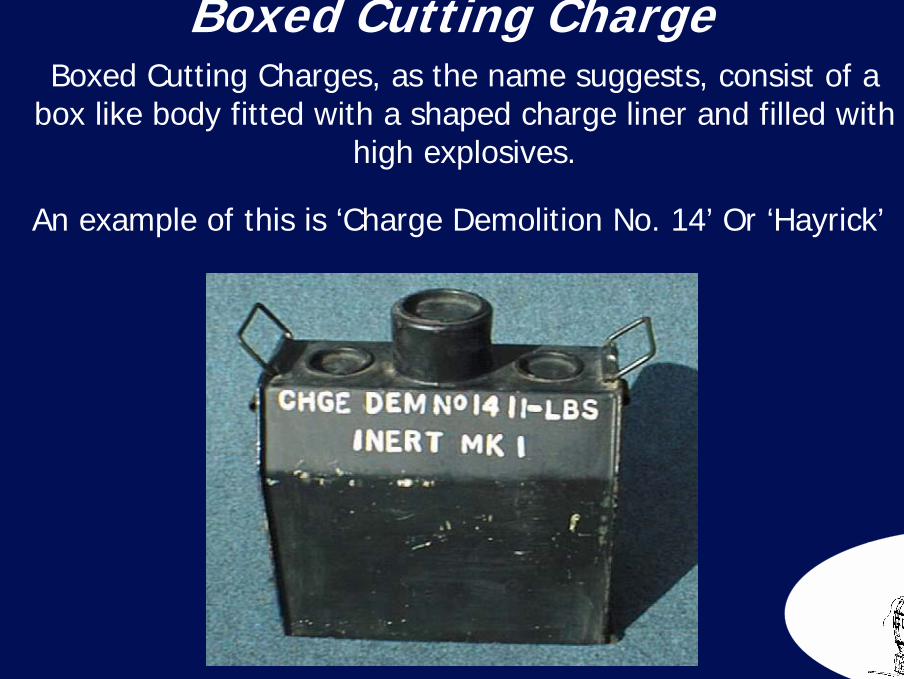
80Boxed Cutting Charge
Boxed Cutting Charges, as the name suggests, consist of a box like body fitted with a shaped charge liner and filled with
high explosives.
An example of this is ‘Charge Demolition No. 14’ Or ‘Hayrick’

81
‘Hayrick’ Charges can be joined together by inserting pins through the fittings on each end, to form a ‘necklace’ around the structure to be cut.
Boxed Cutting Charge Boxed Cutting Charges, as the name suggests, consist of a box like body
fitted with a shaped charge liner and filled with high explosives.
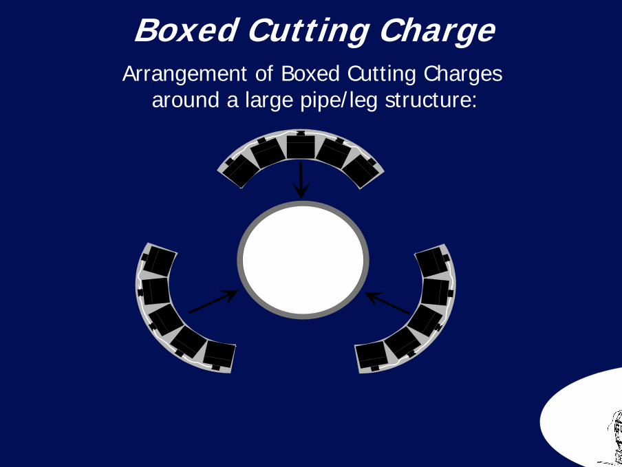
82Boxed Cutting Charge Arrangement of Boxed Cutting Charges
around a large pipe/leg structure:
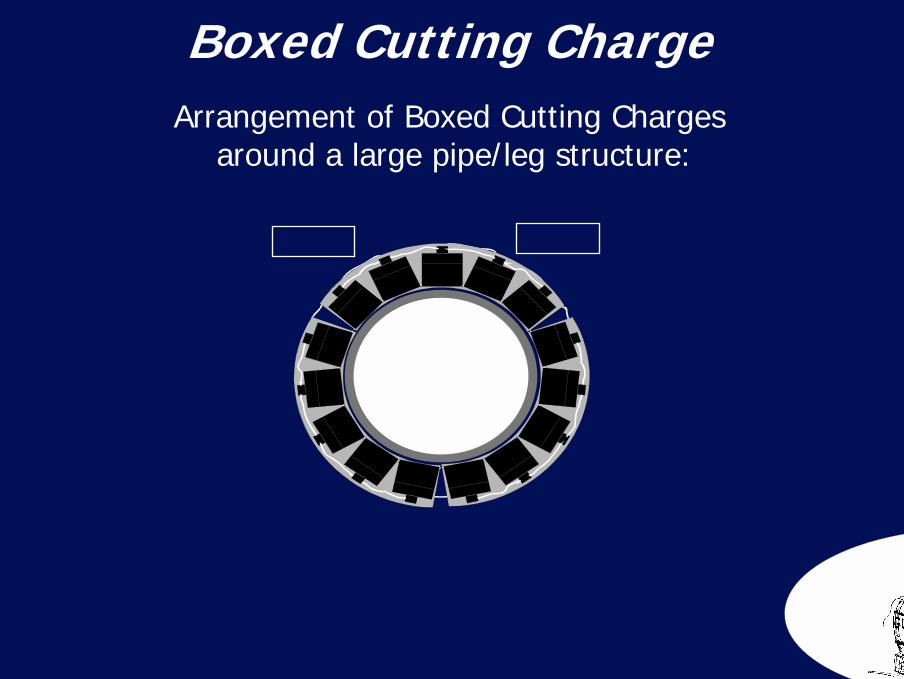
83Boxed Cutting Charge Arrangement of Boxed Cutting Charges
around a large pipe/leg structure:
84
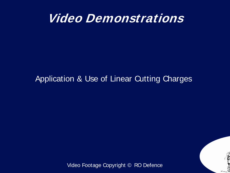
Video Demonstrations
Video Footage Copyright © RO Defence
Application & Use of Linear Cutting Charges

Shockwave Mitigation
Section 4
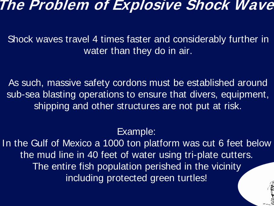
86The Problem of Explosive Shock Waves
Example: In the Gulf of Mexico a 1000 ton platform was cut 6 feet below
the mud line in 40 feet of water using tri-plate cutters.The entire fish population perished in the vicinity
including protected green turtles!
Shock waves travel 4 times faster and considerably further in water than they do in air.
As such, massive safety cordons must be established around sub-sea blasting operations to ensure that divers, equipment,
shipping and other structures are not put at risk.
87A Solution to Explosive Shock Waves
Experiments have been done with different shock mitigation materials, with a view to developing an effective means of
mitigating both air and water born shock waves in the marine environment.
To date considerable successes have been recorded and reductions of peak overpressures in excess of one order of magnitude have been achieved!
88
A Solution to Explosive Shock Waves
This was directly compared with a firing of the same sizesurrounded by a mitigating curtain.
Example:
100kg of High Explosive was detonated in air.the peak overpressures were recorded.
The pressure measured at 15 metres from the chargewas so small that a person could have stood
there and suffered no ill effects!
89
Video Demonstrations
Shock Wave Mitigation Experiments
90
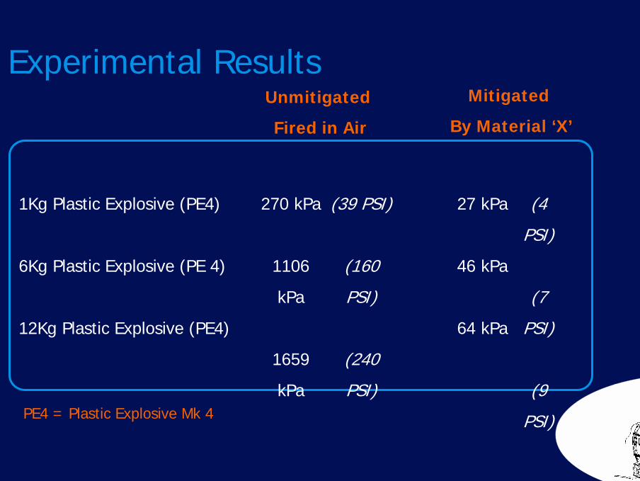
1Kg Plastic Explosive (PE4)
6Kg Plastic Explosive (PE 4)
12Kg Plastic Explosive (PE4)
270 kPa
1106
kPa
1659
kPa
Unmitigated
Fired in Air
Mitigated
By Material ‘X’
PE4 = Plastic Explosive Mk 4
Experimental Results
27 kPa
46 kPa
64 kPa
(39 PSI)
(160
PSI)
(240
PSI)
(4
PSI)
(7
PSI)
(9
PSI)
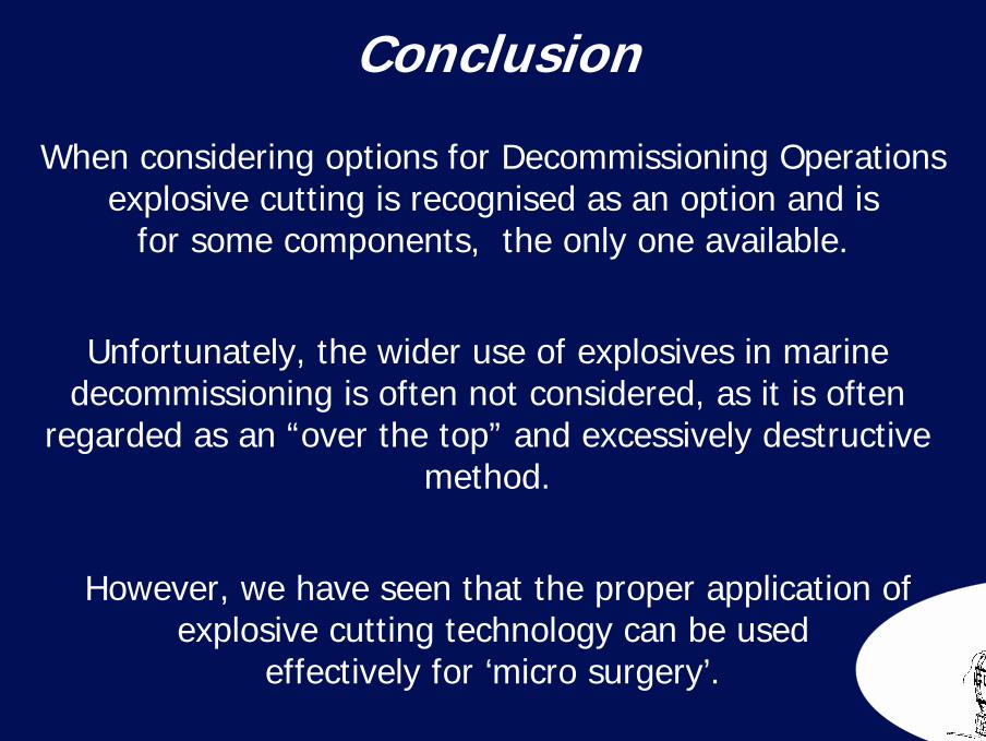
91Conclusion
When considering options for Decommissioning Operations explosive cutting is recognised as an option and is
for some components, the only one available.
Unfortunately, the wider use of explosives in marine decommissioning is often not considered, as it is often
regarded as an “over the top” and excessively destructive method.
However, we have seen that the proper application ofexplosive cutting technology can be used
effectively for ‘micro surgery’.
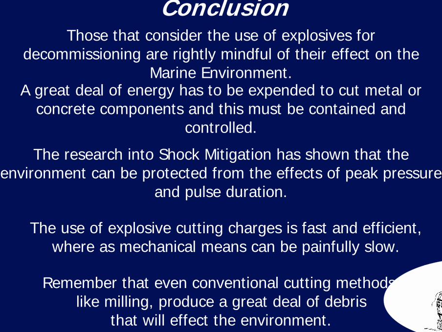
92Conclusion
The research into Shock Mitigation has shown that the environment can be protected from the effects of peak pressure
and pulse duration.
Those that consider the use of explosives for decommissioning are rightly mindful of their effect on the
Marine Environment.
The use of explosive cutting charges is fast and efficient, where as mechanical means can be painfully slow.
A great deal of energy has to be expended to cut metal or concrete components and this must be contained and
controlled.
Remember that even conventional cutting methods,like milling, produce a great deal of debris
that will effect the environment.
93Any Questions?
94Stephen Miller M.I.Exp.E.
Explosives Consultant
152, Ayelands,New Ash Green,
Longfield,Kent.
DA3 8JU
Tel: 01474 874127 Mobile: 07947 835347
Fax: 01474 874127
E-Mail: [email protected]
Website: WWW.LiveActionFX.Com