hierarchical modeling - college of computing & informatics
TRANSCRIPT
Hierarchical Modeling
CS 432 Interactive Computer GraphicsProf. David E. Breen
Department of Computer Science
1E. Angel and D. Shreiner: Interactive Computer Graphics 6E © Addison-Wesley 2012
2E. Angel and D. Shreiner: Interactive Computer Graphics 6E © Addison-Wesley 2012
Objectives
• Examine the limitations of linear modeling- Symbols and instances
• Introduce hierarchical models- Articulated models- Robots
• Introduce Tree and DAG models
3E. Angel and D. Shreiner: Interactive Computer Graphics 6E © Addison-Wesley 2012
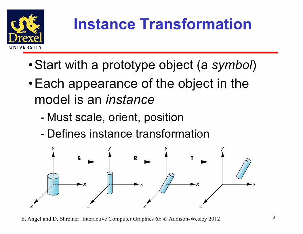
Instance Transformation
• Start with a prototype object (a symbol)•Each appearance of the object in the model is an instance- Must scale, orient, position- Defines instance transformation
4E. Angel and D. Shreiner: Interactive Computer Graphics 6E © Addison-Wesley 2012
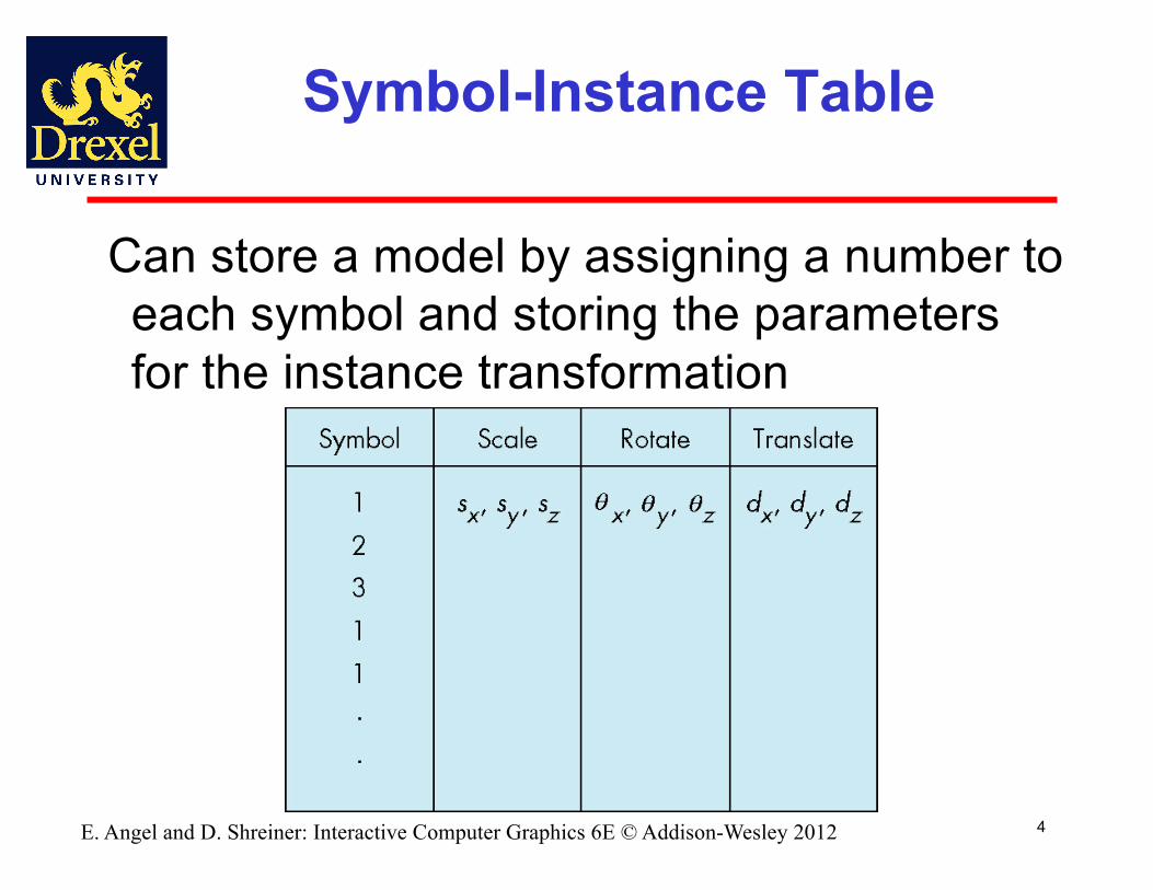
Symbol-Instance Table
Can store a model by assigning a number to each symbol and storing the parameters for the instance transformation
5E. Angel and D. Shreiner: Interactive Computer Graphics 6E © Addison-Wesley 2012
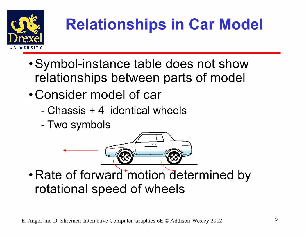
Relationships in Car Model
• Symbol-instance table does not show relationships between parts of model
• Consider model of car- Chassis + 4 identical wheels- Two symbols
• Rate of forward motion determined by rotational speed of wheels

6E. Angel and D. Shreiner: Interactive Computer Graphics 6E © Addison-Wesley 2012
Structure Through Function Calls
car(speed){
chassis()wheel(right_front);wheel(left_front);wheel(right_rear);wheel(left_rear);
}
• Fails to show relationships well• Look at problem using a graph
7E. Angel and D. Shreiner: Interactive Computer Graphics 6E © Addison-Wesley 2012
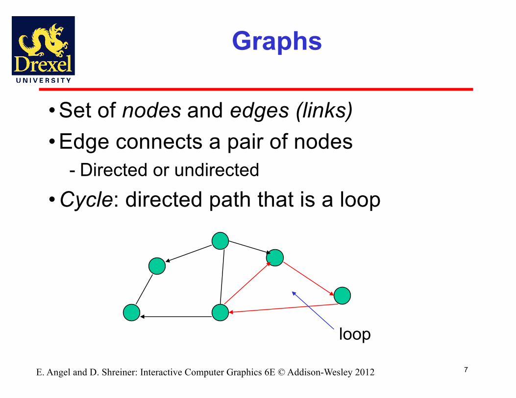
Graphs
• Set of nodes and edges (links)• Edge connects a pair of nodes
- Directed or undirected• Cycle: directed path that is a loop
loop

8E. Angel and D. Shreiner: Interactive Computer Graphics 6E © Addison-Wesley 2012
Tree
• Graph in which each node (except the root) has exactly one parent node
- May have multiple children- Leaf or terminal node: no children
root node
leaf node
9E. Angel and D. Shreiner: Interactive Computer Graphics 6E © Addison-Wesley 2012
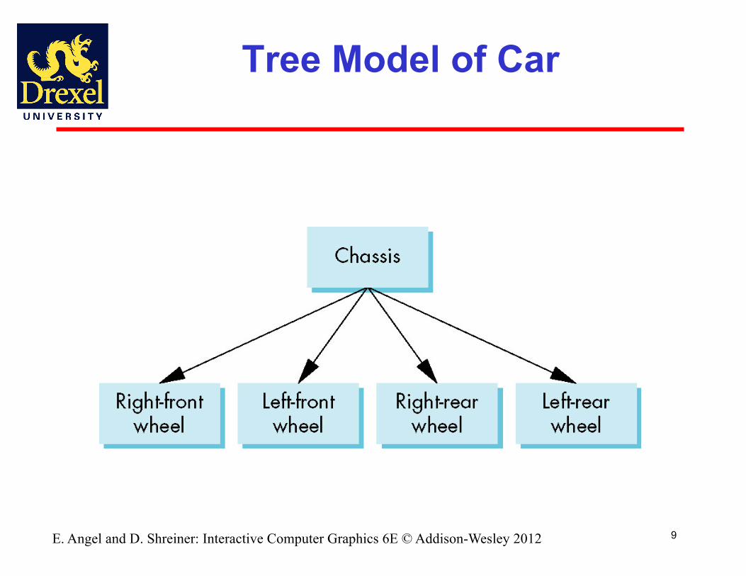
Tree Model of Car
10E. Angel and D. Shreiner: Interactive Computer Graphics 6E © Addison-Wesley 2012
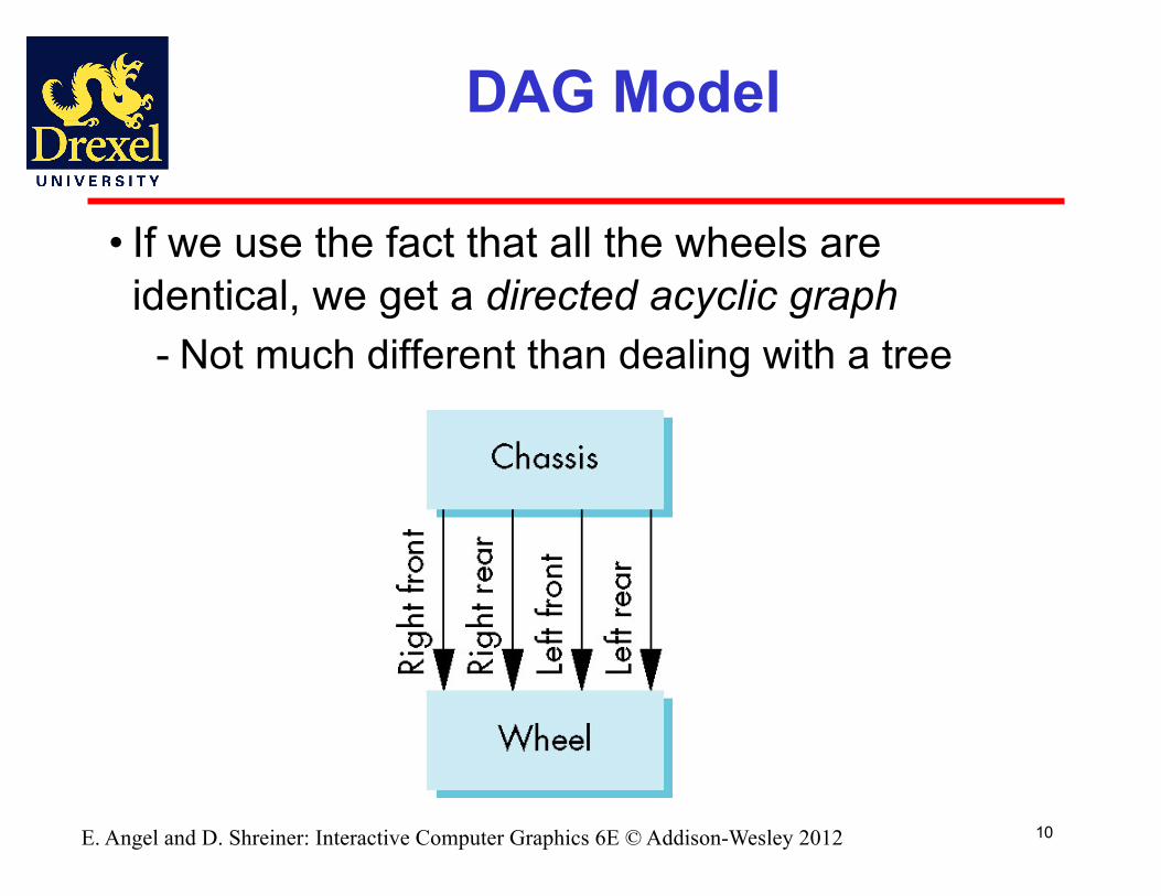
DAG Model
• If we use the fact that all the wheels are identical, we get a directed acyclic graph
- Not much different than dealing with a tree
11E. Angel and D. Shreiner: Interactive Computer Graphics 6E © Addison-Wesley 2012
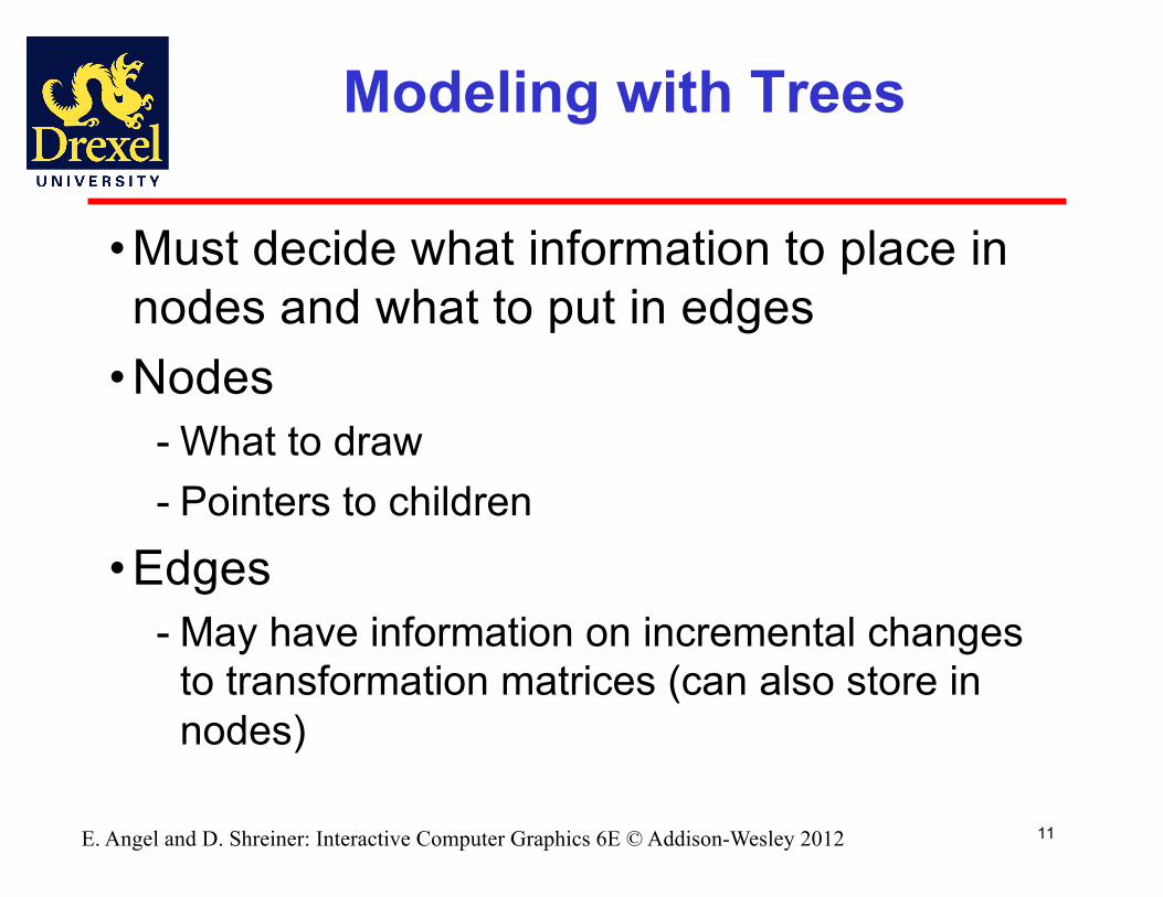
Modeling with Trees
• Must decide what information to place in nodes and what to put in edges
• Nodes- What to draw- Pointers to children
• Edges- May have information on incremental changes
to transformation matrices (can also store in nodes)

• Issue: the world has many different relative frames of reference
• How do we transform among them?• Example: CAD Assemblies & Animation Models
12
Transformations to Change Coordinate Systems
13
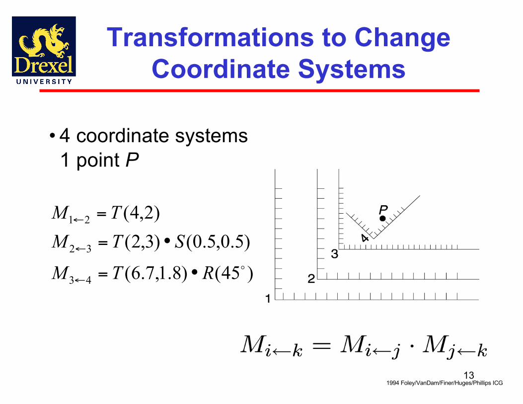
Transformations to Change Coordinate Systems
• 4 coordinate systems1 point P
)45()8.1,7.6(
)5.0,5.0()3,2()2,4(
43
32
21
RTMSTM
TM
•=
•=
=
←
←
←
1994 Foley/VanDam/Finer/Huges/Phillips ICG
14
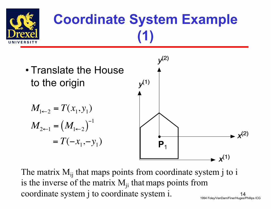
Coordinate System Example (1)
• Translate the House to the origin
€
M1←2 = T(x1,y1)
M2←1 = M1←2( )−1
= T(−x1,−y1)
1994 Foley/VanDam/Finer/Huges/Phillips ICG
The matrix Mij that maps points from coordinate system j to i is the inverse of the matrix Mji that maps points from coordinate system j to coordinate system i.
P1

15
• Transformation Composition:
€
M5←1 = M5←4 •M4←3 •M3←2 •M2←1
1994 Foley/VanDam/Finer/Huges/Phillips ICG
Coordinate System Example (2)

16
World Coordinates and Local Coordinates
• To move the tricycle, we need to know how all of its parts relate to the WCS
• Example: front wheel rotates on the ground wrt the front wheel’s z axis:Coordinates of P in wheel coordinate system:
1994 Foley/VanDam/Finer/Huges/Phillips ICG€
P(wo) = T(αr,0,0) ⋅ Rz(α) ⋅ P(wh )
€
P'(wh )= Rz (α) ⋅ P(wh )
17E. Angel and D. Shreiner: Interactive Computer Graphics 6E © Addison-Wesley 2012
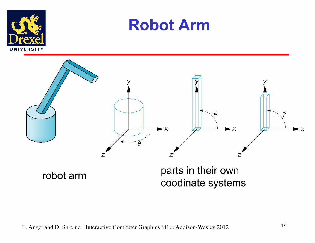
Robot Arm
robot arm parts in their own coodinate systems

18E. Angel and D. Shreiner: Interactive Computer Graphics 6E © Addison-Wesley 2012
Articulated Models
• Robot arm is an example of an articulated model
- Parts connected at joints- Can specify state of model by
giving all joint angles

19E. Angel and D. Shreiner: Interactive Computer Graphics 6E © Addison-Wesley 2012
Relationships in Robot Arm
• Base rotates independently- Single angle determines position
• Lower arm attached to base- Its position depends on rotation of base- Must also translate relative to base and rotate
about connecting joint• Upper arm attached to lower arm
- Its position depends on both base and lower arm- Must translate relative to lower arm and rotate
about joint connecting to lower arm

20E. Angel and D. Shreiner: Interactive Computer Graphics 6E © Addison-Wesley 2012
Required Matrices
• Rotation of base: Rb
- Apply M = Rb to base• Translate lower arm relative to base: Tla
• Rotate lower arm around joint: Rla
- Apply M = Rb Tla Rla to lower arm• Translate upper arm relative to lower arm: Tua
• Rotate upper arm around joint: Rua
- Apply M = Rb Tla Rla Tua Rua to upper arm

21
WebGL Code for Robot
Angel and Shreiner: Interactive Computer Graphics 7E © Addison-Wesley 2015
var render = function() {gl.clear( gl.COLOR_BUFFER_BIT | gl.DEPTH_BUFFER_BIT );modelViewMatrix = rotate(theta[Base], 0, 1, 0 );base();modelViewMatrix = mult(modelViewMatrix,
translate(0.0, BASE_HEIGHT, 0.0));modelViewMatrix = mult(modelViewMatrix,
rotate(theta[LowerArm], 0, 0, 1 ));lowerArm();modelViewMatrix = mult(modelViewMatrix,
translate(0.0, LOWER_ARM_HEIGHT, 0.0));modelViewMatrix = mult(modelViewMatrix,
rotate(theta[UpperArm], 0, 0, 1) );upperArm();requestAnimFrame(render);
}

23E. Angel and D. Shreiner: Interactive Computer Graphics 6E © Addison-Wesley 2012
OpenGL Code for Robot
• At each level of hierarchy, calculate ModelView matrix in application.
• Send matrix to shaders• Draw geometry for one level of hierarchy• Apply ModelView matrix in shader
24E. Angel and D. Shreiner: Interactive Computer Graphics 6E © Addison-Wesley 2012
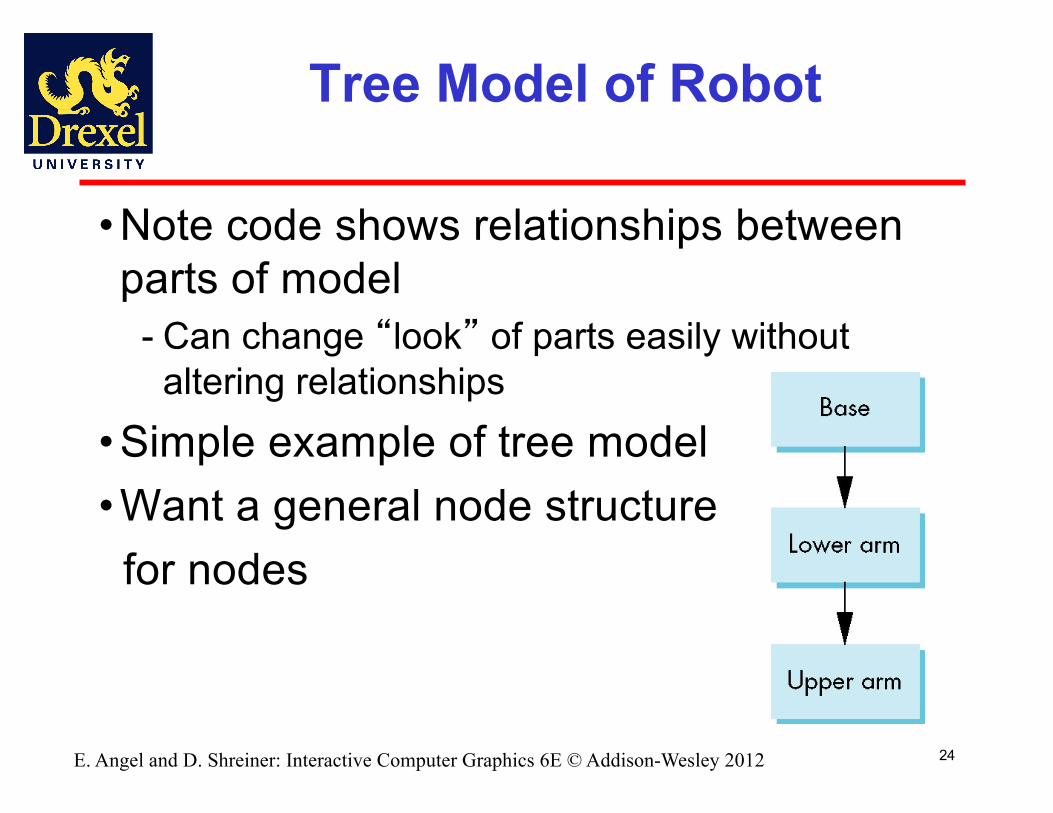
Tree Model of Robot
• Note code shows relationships between parts of model
- Can change “look” of parts easily without altering relationships
• Simple example of tree model• Want a general node structure
for nodes
25E. Angel and D. Shreiner: Interactive Computer Graphics 6E © Addison-Wesley 2012
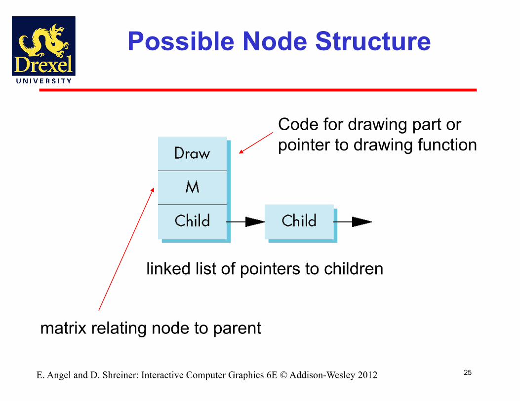
Possible Node Structure
Code for drawing part orpointer to drawing function
linked list of pointers to children
matrix relating node to parent
26E. Angel and D. Shreiner: Interactive Computer Graphics 6E © Addison-Wesley 2012
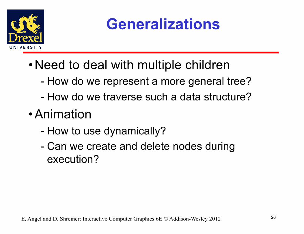
Generalizations
• Need to deal with multiple children- How do we represent a more general tree?- How do we traverse such a data structure?
• Animation- How to use dynamically?- Can we create and delete nodes during
execution?

27E. Angel and D. Shreiner: Interactive Computer Graphics 6E © Addison-Wesley 2012
Objectives
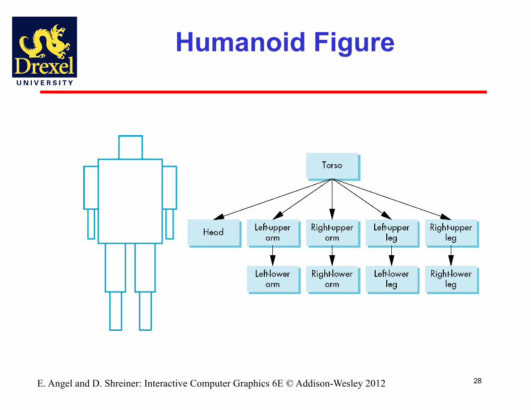
• Build a tree-structured model of a humanoid figure
• Examine various traversal strategies• Build a generalized tree-model structure that is independent of the particular model
28E. Angel and D. Shreiner: Interactive Computer Graphics 6E © Addison-Wesley 2012
Humanoid Figure
29E. Angel and D. Shreiner: Interactive Computer Graphics 6E © Addison-Wesley 2012
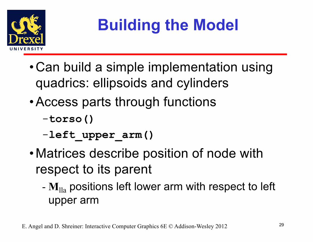
Building the Model
• Can build a simple implementation using quadrics: ellipsoids and cylinders
• Access parts through functions-torso()-left_upper_arm()
• Matrices describe position of node with respect to its parent
- Mlla positions left lower arm with respect to left upper arm

30E. Angel and D. Shreiner: Interactive Computer Graphics 6E © Addison-Wesley 2012
Tree with Matrices

31E. Angel and D. Shreiner: Interactive Computer Graphics 6E © Addison-Wesley 2012
Display and Traversal
• The position of the figure is determined by 10 joint angles (two for the head and one for each other part)
• Display of the tree requires a graph traversal
- Visit each node once- Display function at each node that describes
the part associated with the node, applying the correct transformation matrix for position and orientation
32E. Angel and D. Shreiner: Interactive Computer Graphics 6E © Addison-Wesley 2012
Transformation Matrices
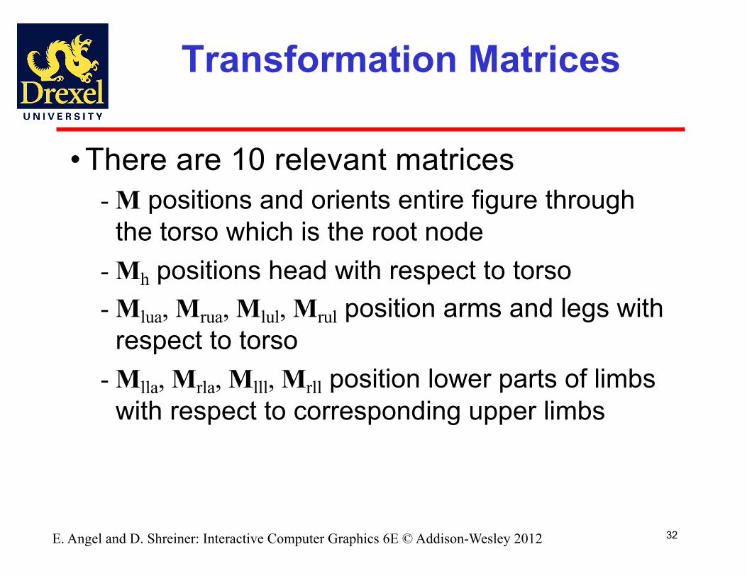
• There are 10 relevant matrices- M positions and orients entire figure through
the torso which is the root node- Mh positions head with respect to torso- Mlua, Mrua, Mlul, Mrul position arms and legs with
respect to torso- Mlla, Mrla, Mlll, Mrll position lower parts of limbs
with respect to corresponding upper limbs
33E. Angel and D. Shreiner: Interactive Computer Graphics 6E © Addison-Wesley 2012
Stack-based Traversal
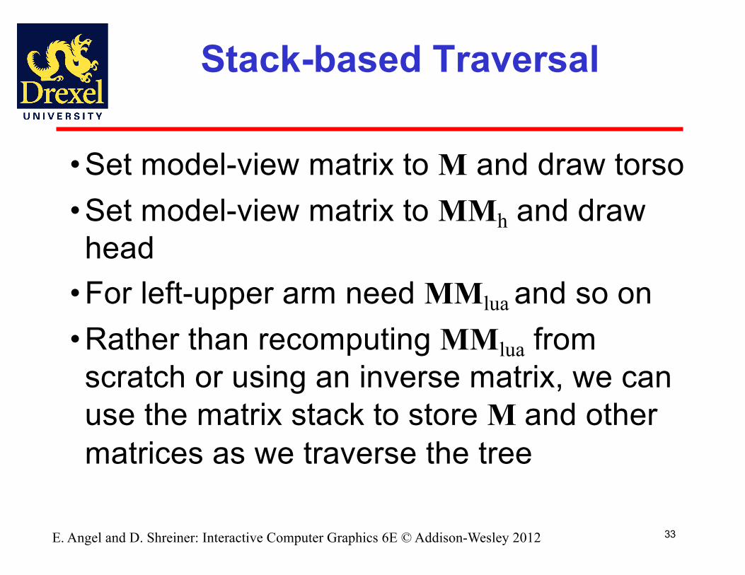
• Set model-view matrix to M and draw torso• Set model-view matrix to MMh and draw head
• For left-upper arm need MMlua and so on• Rather than recomputing MMlua from scratch or using an inverse matrix, we can use the matrix stack to store M and other matrices as we traverse the tree
34E. Angel and D. Shreiner: Interactive Computer Graphics 6E © Addison-Wesley 2012
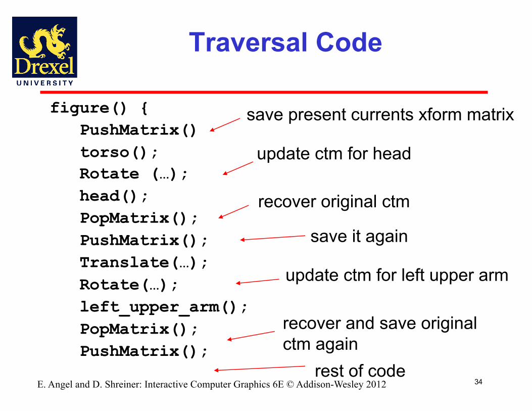
Traversal Code
figure() {PushMatrix()torso();Rotate (…);head();PopMatrix();PushMatrix();Translate(…);Rotate(…);left_upper_arm();PopMatrix();PushMatrix();
save present currents xform matrix
update ctm for head
recover original ctm
save it again
update ctm for left upper arm
recover and save original ctm again
rest of code
35E. Angel and D. Shreiner: Interactive Computer Graphics 6E © Addison-Wesley 2012
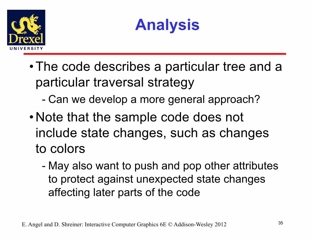
Analysis
• The code describes a particular tree and a particular traversal strategy
- Can we develop a more general approach?• Note that the sample code does not include state changes, such as changes to colors
- May also want to push and pop other attributes to protect against unexpected state changes affecting later parts of the code

36E. Angel and D. Shreiner: Interactive Computer Graphics 6E © Addison-Wesley 2012
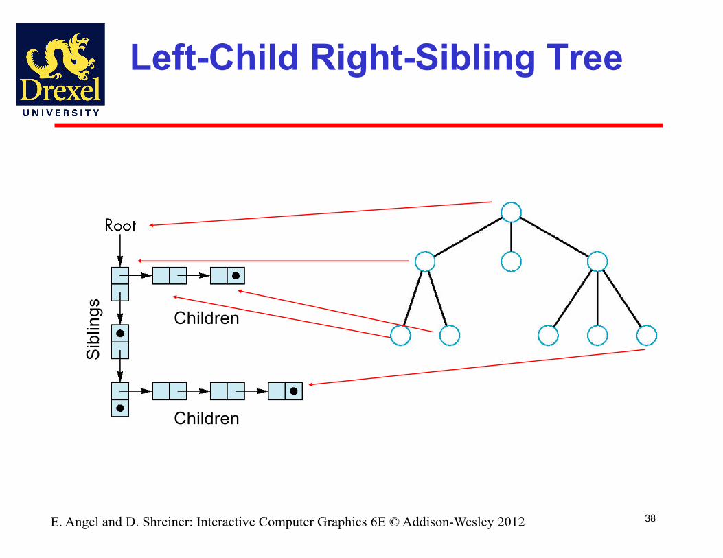
General Tree Data Structure
• Need a data structure to represent tree and an algorithm to traverse the tree
• We will use a left-child right siblingstructure
- Uses linked lists- Each node in data structure has two pointers- Left: linked list of children - Right: next node (i.e. siblings)
38E. Angel and D. Shreiner: Interactive Computer Graphics 6E © Addison-Wesley 2012
Left-Child Right-Sibling Tree
Children
Children
Sibl
ings
39E. Angel and D. Shreiner: Interactive Computer Graphics 6E © Addison-Wesley 2012
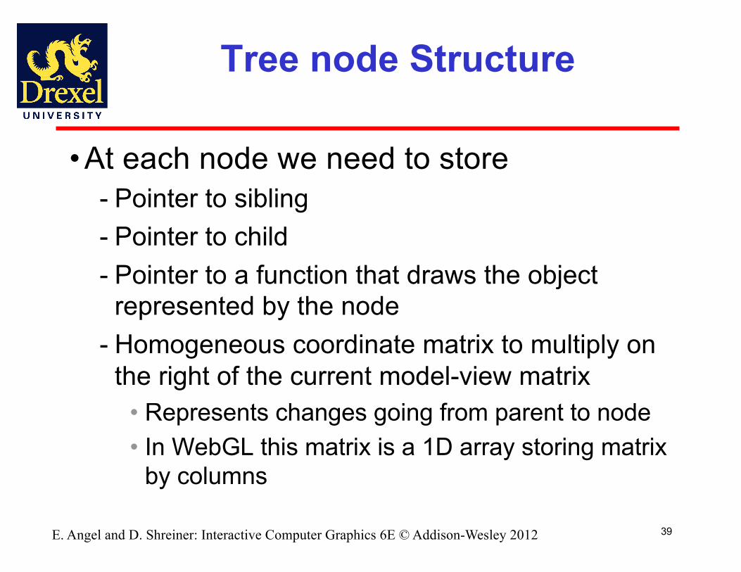
Tree node Structure
• At each node we need to store - Pointer to sibling- Pointer to child- Pointer to a function that draws the object
represented by the node- Homogeneous coordinate matrix to multiply on
the right of the current model-view matrix• Represents changes going from parent to node• In WebGL this matrix is a 1D array storing matrix
by columns
40
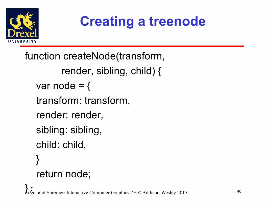
Creating a treenode
function createNode(transform, render, sibling, child) {
var node = {transform: transform,render: render,sibling: sibling,child: child,}return node;
};Angel and Shreiner: Interactive Computer Graphics 7E © Addison-Wesley 2015

41
Initializing Nodes
function initNodes(Id) {var m = mat4();
switch(Id) {case torsoId:
m = rotate(theta[torsoId], 0, 1, 0 );figure[torsoId] = createNode( m, torso, null, headId );break;
case head1Id:case head2Id:
m = translate(0.0, torsoHeight+0.5*headHeight, 0.0);m = mult(m, rotate(theta[head1Id], 1, 0, 0))m = mult(m,
rotate(theta[head2Id], 0, 1, 0));m = mult(m, translate(0.0, -0.5*headHeight, 0.0));figure[headId] = createNode( m, head, leftUpperArmId, null);break;
Angel and Shreiner: Interactive Computer Graphics 7E © Addison-Wesley 2015
42
Notes
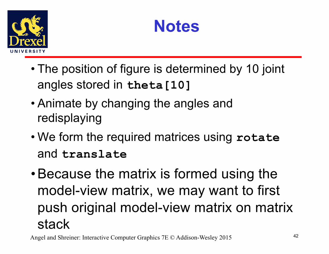
• The position of figure is determined by 10 joint angles stored in theta[10]
• Animate by changing the angles and redisplaying
• We form the required matrices using rotateand translate
• Because the matrix is formed using the model-view matrix, we may want to first push original model-view matrix on matrix stack
Angel and Shreiner: Interactive Computer Graphics 7E © Addison-Wesley 2015

43
Preorder Traversal
function traverse(Id) {if(Id == null) return;stack.push(modelViewMatrix);modelViewMatrix = mult(modelViewMatrix, figure[Id].transform);figure[Id].render();if(figure[Id].child != null) traverse(figure[Id].child); modelViewMatrix = stack.pop();if(figure[Id].sibling != null) traverse(figure[Id].sibling);
}var render = function() {
gl.clear( gl.COLOR_BUFFER_BIT );traverse(torsoId);requestAnimFrame(render);
}
Angel and Shreiner: Interactive Computer Graphics 7E © Addison-Wesley 2015
44
Traversal Code & Matrices
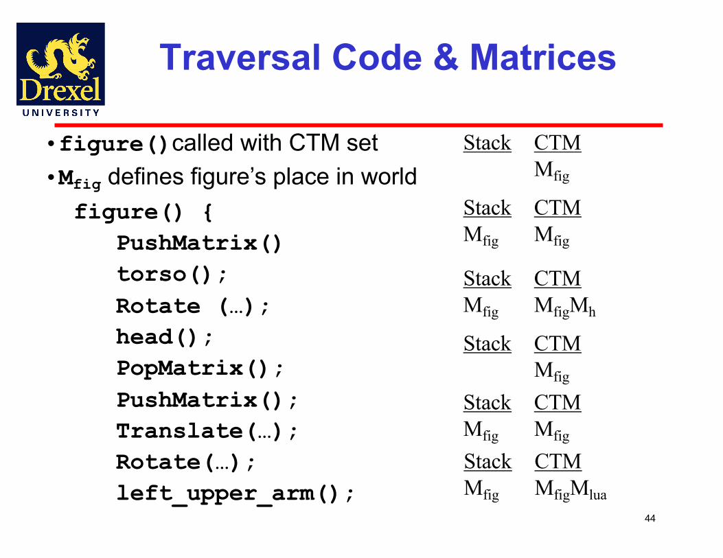
figure() {PushMatrix()torso();Rotate (…);head();PopMatrix();PushMatrix();Translate(…);Rotate(…);left_upper_arm();
Stack CTMMfig
StackMfig
CTMMfig
StackMfig
CTMMfigMh
Stack CTMMfig
StackMfig
CTMMfig
StackMfig
CTMMfigMlua
•figure()called with CTM set•Mfig defines figure’s place in world

45
Traversal Code & Matrices
PushMatrix()Translate(…);Rotate(…);left_lower_arm();PopMatrix();PopMatrix();PushMatrix()Translate(…);Rotate(…);right_upper_arm();
……
StackMfigMluaMfig
CTMMfigMlua
StackMfigMluaMfig
CTMMfigMluaMlla
StackMfig
CTMMfigMlua
Stack CTMMfig
StackMfig
CTMMfig
StackMfig
CTMMfigMrua
46
Notes
• We must save model-view matrix before multiplying it by node matrix
- Updated matrix applies to children of node but not to siblings which contain their own matrices
• The traversal program applies to any left-child right-sibling tree
- The particular tree is encoded in the definition of the individual nodes
• The order of traversal matters because of possible state changes in the functions
Angel and Shreiner: Interactive Computer Graphics 7E © Addison-Wesley 2015

47
Dynamic Trees
• Because we are using JS, the nodes and the node structure can be changed during execution
• Definition of nodes and traversal are essentially the same as before but we can add and delete nodes during execution
• In desktop OpenGL, if we use pointers, the structure can be dynamic
Angel and Shreiner: Interactive Computer Graphics 7E © Addison-Wesley 2015

56
Solids and Solid Modeling
• Solid modeling introduces a mathematical theory of solid shape
- Domain of objects- Set of operations on the domain of objects- Representation that is
• Unambiguous• Accurate• Unique• Compact• Efficient
57
Solid Objects and Operations
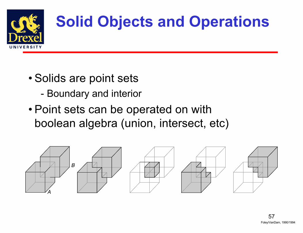
• Solids are point sets- Boundary and interior
• Point sets can be operated on with boolean algebra (union, intersect, etc)
Foley/VanDam, 1990/1994
58
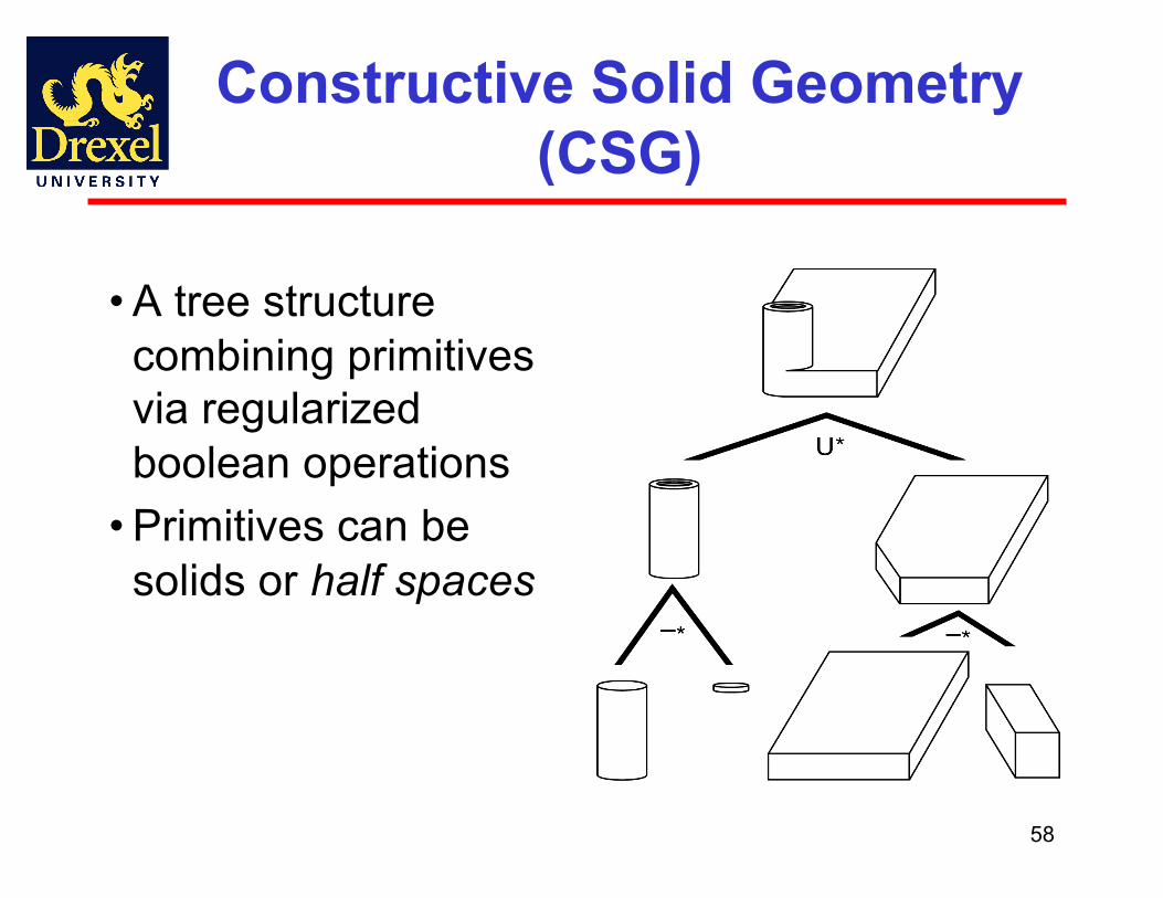
Constructive Solid Geometry (CSG)
• A tree structure combining primitives via regularized boolean operations
• Primitives can be solids or half spaces
59
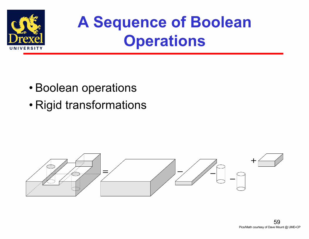
A Sequence of Boolean Operations
• Boolean operations • Rigid transformations
Pics/Math courtesy of Dave Mount @ UMD-CP

60
The Induced CSG Tree
Pics/Math courtesy of Dave Mount @ UMD-CP
61
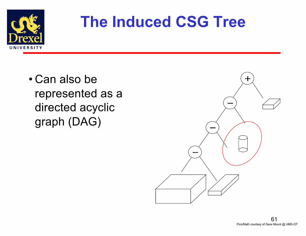
The Induced CSG Tree
• Can also be represented as a directed acyclic graph (DAG)
Pics/Math courtesy of Dave Mount @ UMD-CP

62
Issues with Constructive Solid Geometry
• Non-uniqueness• Choice of primitives• How to handle more complex modeling?
- Sculpted surfaces? Deformable objects?
63
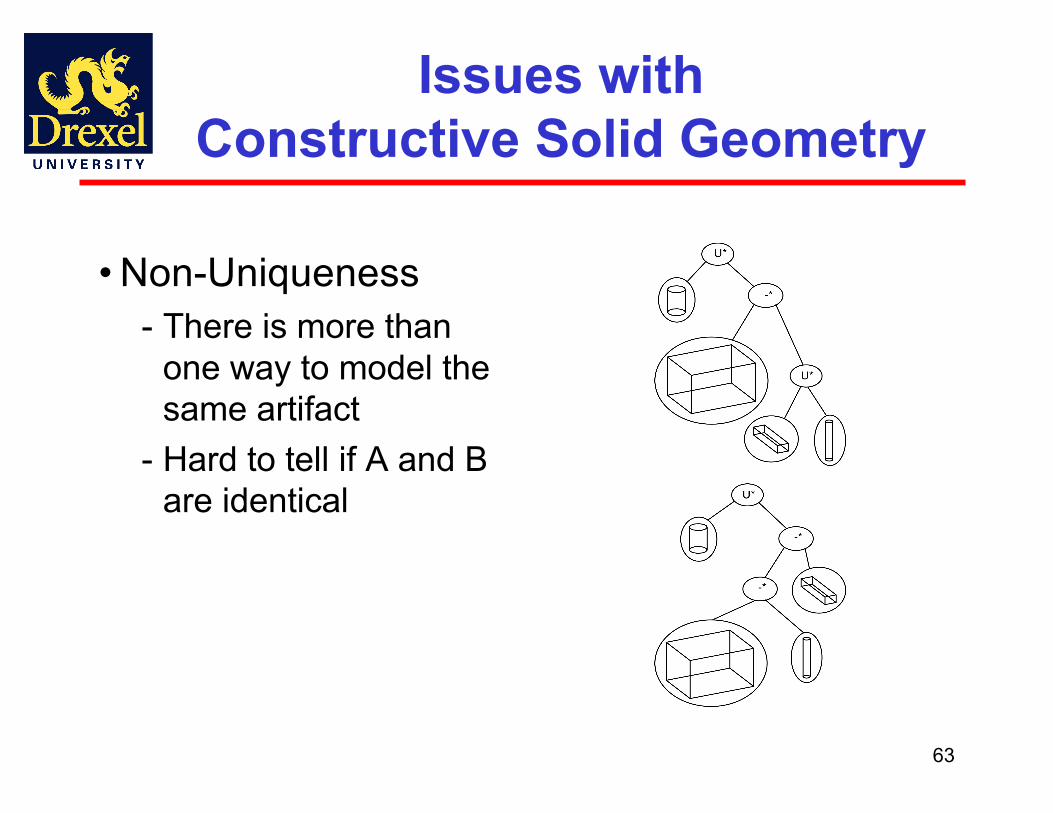
Issues with Constructive Solid Geometry
• Non-Uniqueness- There is more than
one way to model the same artifact
- Hard to tell if A and B are identical
64
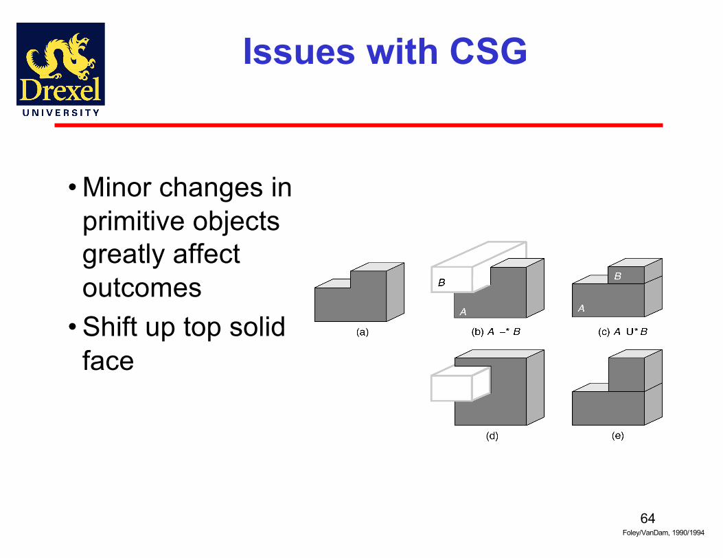
Issues with CSG
• Minor changes in primitive objects greatly affect outcomes
• Shift up top solid face
Foley/VanDam, 1990/1994
65
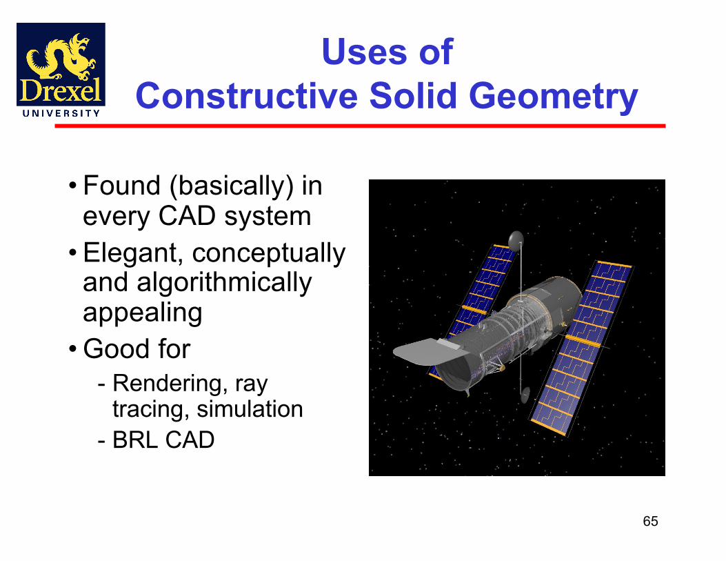
Uses of Constructive Solid Geometry
• Found (basically) in every CAD system
• Elegant, conceptually and algorithmically appealing
• Good for- Rendering, ray
tracing, simulation- BRL CAD
Go to Solid Modeling Slides
66

Graphical Objects and Scene Graphs
67Angel and Shreiner: Interactive Computer Graphics 7E © Addison-Wesley 2015

68
Objectives
• Introduce graphical objects• Generalize the notion of objects to include lights, cameras, attributes
• Introduce scene graphs • three.js (threejs.org)
Angel and Shreiner: Interactive Computer Graphics 7E © Addison-Wesley 2015
69
Limitations of Immediate Mode Graphics
• When we define a geometric object in an application, upon execution of the code the object is passed through the pipeline
• It then disappeared from the graphical system
• To redraw the object, either changed or the same, we had to reexecute the code
• Display lists provided only a partial solution to this problem
Angel and Shreiner: Interactive Computer Graphics 7E © Addison-Wesley 2015
Retained Mode Graphics
• Display lists were server side• GPUs allowed data to be stored on GPU• Essentially all immediate mode functions have been deprecated
• Nevertheless, OpenGL is a low level API
70Angel and Shreiner: Interactive Computer Graphics 7E © Addison-Wesley 2015
71
OpenGL and Objects
• OpenGL lacks an object orientation• Consider, for example, a green sphere
- We can model the sphere with polygons- Its color is determined by the OpenGL state and
is not a property of the object- Loose linkage with vertex attributes
• Defies our notion of a physical object• We can try to build better objects in code using object-oriented languages/techniques
Angel and Shreiner: Interactive Computer Graphics 7E © Addison-Wesley 2015
72
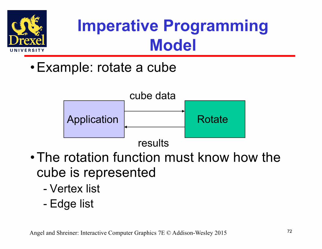
Imperative Programming Model
• Example: rotate a cube
• The rotation function must know how the cube is represented
- Vertex list- Edge list
Application Rotate
cube data
results
Angel and Shreiner: Interactive Computer Graphics 7E © Addison-Wesley 2015

73
Object-Oriented Programming Model
Application Cube Object
• In this model, the representation is stored with the object
• The application sends a message to the object• The object contains functions (methods) which allow it to transform itself
message
Angel and Shreiner: Interactive Computer Graphics 7E © Addison-Wesley 2015

74
C/C++/Java/JS
• Can try to use C structs to build objects • C++/Java/JS provide better support
- Use class construct- With C++ we can hide implementation using
public, private, and protected members i- JS provides multiple methods for object
Angel and Shreiner: Interactive Computer Graphics 7E © Addison-Wesley 2015

75
Cube Object
• Suppose that we want to create a simple cube object that we can scale, orient, position and set its color directly through code such asvar mycube = new Cube();mycube.color[0]=1.0;mycube.color[1]= mycube.color[2]=0.0;mycube.matrix[0][0]=………
Angel and Shreiner: Interactive Computer Graphics 7E © Addison-Wesley 2015

76
Cube Object Functions
• We would also like to have functions that act on the cube such as -mycube.translate(1.0, 0.0,0.0);-mycube.rotate(theta, 1.0, 0.0, 0.0);-setcolor(mycube, 1.0, 0.0, 0.0);
• We also need a way of displaying the cube-mycube.render();
Angel and Shreiner: Interactive Computer Graphics 7E © Addison-Wesley 2015
77
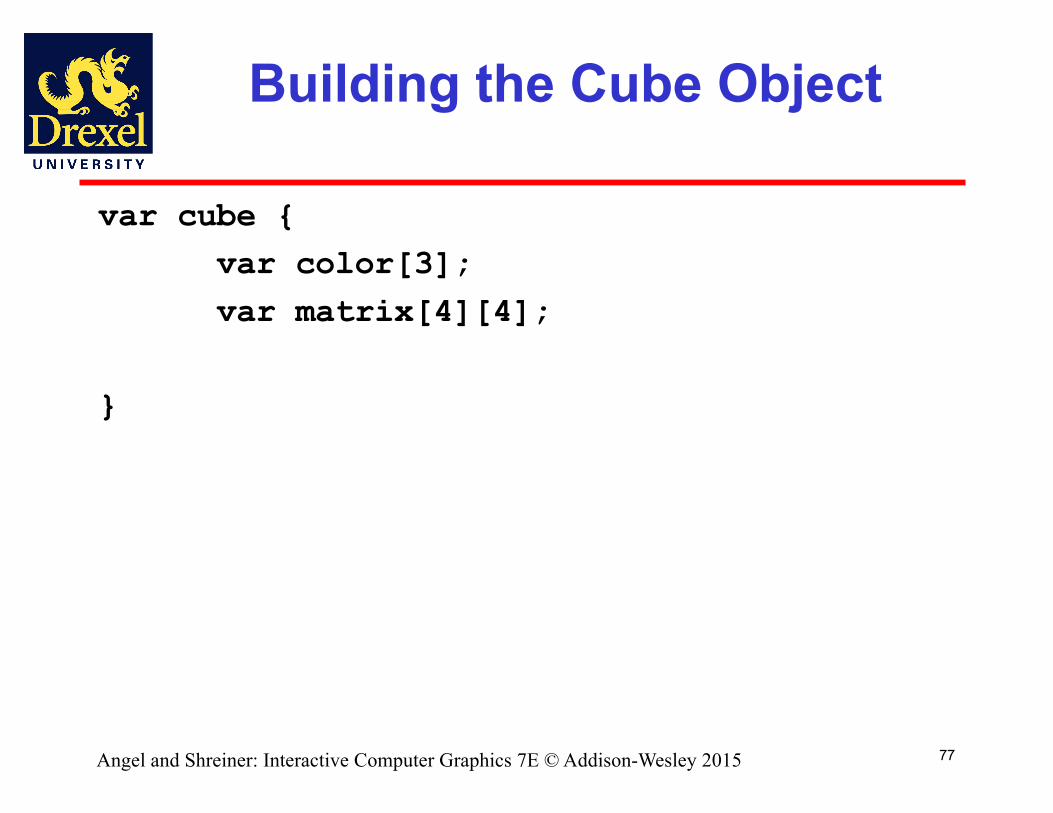
Building the Cube Object
var cube {var color[3];var matrix[4][4];
}
Angel and Shreiner: Interactive Computer Graphics 7E © Addison-Wesley 2015

78
The Implementation
• Can use any implementation in the private part such as a vertex list
• The private part has access to public members and the implementation of class methods can use any implementation without making it visible
• Render method is tricky but it will invoke the standard OpenGL drawing functions
Angel and Shreiner: Interactive Computer Graphics 7E © Addison-Wesley 2015
79
Other Objects
• Other objects have geometric aspects- Cameras- Light sources
• But we should be able to have nongeometric objects too
- Materials- Colors- Transformations (matrices)
Angel and Shreiner: Interactive Computer Graphics 7E © Addison-Wesley 2015
80
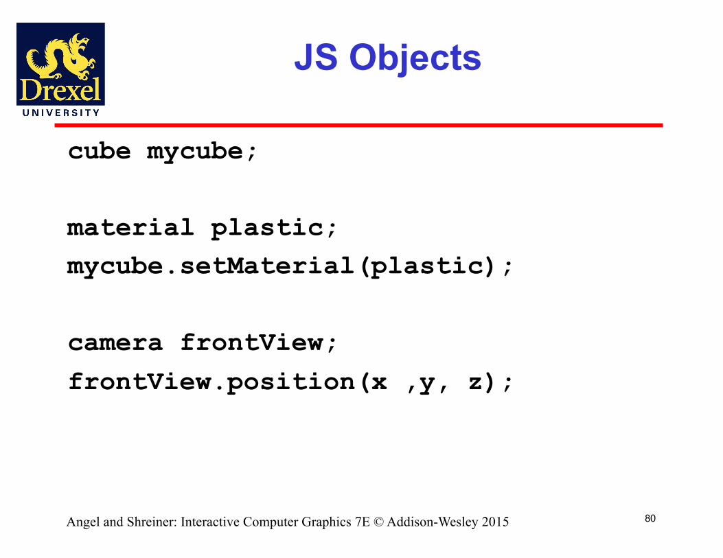
JS Objects
cube mycube;
material plastic;mycube.setMaterial(plastic);
camera frontView;
frontView.position(x ,y, z);
Angel and Shreiner: Interactive Computer Graphics 7E © Addison-Wesley 2015
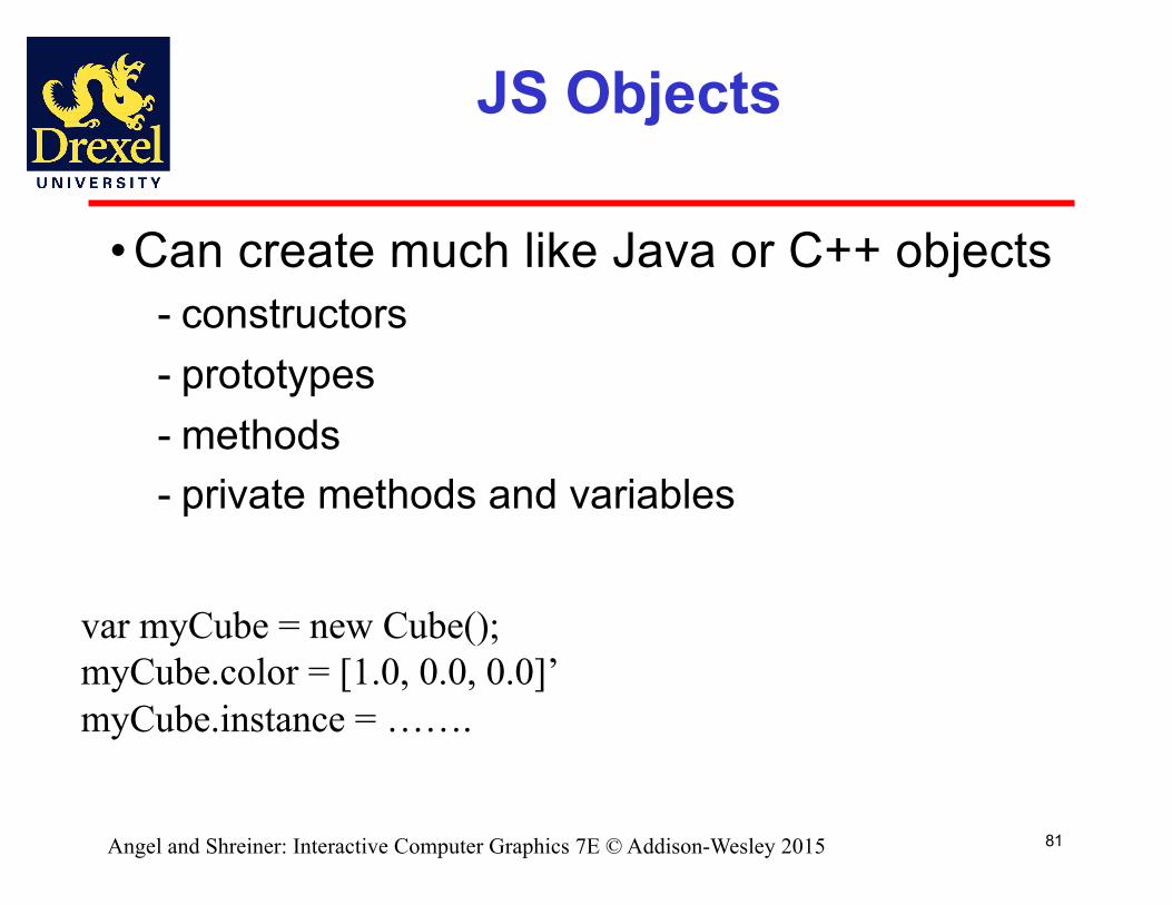
JS Objects
• Can create much like Java or C++ objects- constructors- prototypes- methods- private methods and variables
81
var myCube = new Cube();myCube.color = [1.0, 0.0, 0.0]’myCube.instance = …….
Angel and Shreiner: Interactive Computer Graphics 7E © Addison-Wesley 2015
82
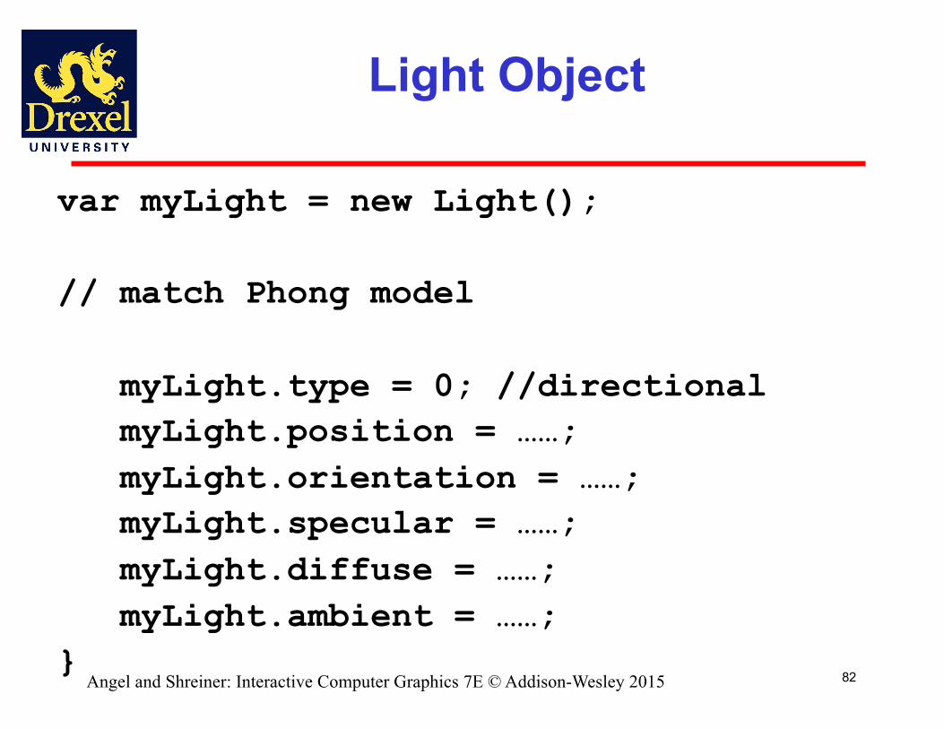
Light Object
var myLight = new Light();
// match Phong model
myLight.type = 0; //directionalmyLight.position = ……;myLight.orientation = ……;myLight.specular = ……;myLight.diffuse = ……;myLight.ambient = ……;
}Angel and Shreiner: Interactive Computer Graphics 7E © Addison-Wesley 2015
83
Scene Descriptions
• If we recall figure model, we saw that - We could describe model either by tree or by
equivalent code- We could write a generic traversal to display
• If we can represent all the elements of a scene (cameras, lights,materials, geometry) as JS objects, we should be able to show them in a tree
- Render scene by traversing this tree
Angel and Shreiner: Interactive Computer Graphics 7E © Addison-Wesley 2015

84
Scene Graph
Scene
CameraObject 1 Object 2Light
Color Material Material Position
Instance Instance RotatePosition
Clip
Angel and Shreiner: Interactive Computer Graphics 7E © Addison-Wesley 2015

85
Traversal
myScene = new Scene();myLight = new Light();myLight.Color = ……;…myscene.Add(myLight);object1 = new Object();object1.color = …myscene.add(object1);……myscene.render();
Angel and Shreiner: Interactive Computer Graphics 7E © Addison-Wesley 2015
Scene Graph History
• OpenGL development based largely on people who wanted to exploit hardware
- real time graphics- animation and simulation- stand-alone applications
• CAD community needed to be able to share databases
- real time not and photorealism not issues- need cross-platform capability- first attempt: PHIGS
86Angel and Shreiner: Interactive Computer Graphics 7E © Addison-Wesley 2015
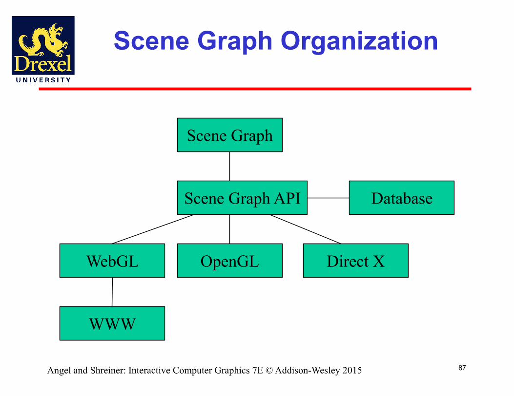
Scene Graph Organization
87
OpenGL
Database
WebGL Direct X
WWW
Scene Graph
Scene Graph API
Angel and Shreiner: Interactive Computer Graphics 7E © Addison-Wesley 2015
88
Inventor and Java3D
• Inventor and Java3D provide a scene graph API • Scene graphs can also be described by a file
(text or binary)- Implementation independent way of
transporting scenes- Supported by scene graph APIs
• However, primitives supported should match capabilities of graphics systems
- Hence most scene graph APIs are built on top of OpenGL, WebGL or DirectX (for PCs)
Angel and Shreiner: Interactive Computer Graphics 7E © Addison-Wesley 2015

89
VRML
• Want to have a scene graph that can be used over the World Wide Web
• Need links to other sites to support distributed data bases
• Virtual Reality Markup Language- Based on Inventor data base- Implemented with OpenGL
Angel and Shreiner: Interactive Computer Graphics 7E © Addison-Wesley 2015

Open Scene Graph
• Supports very complex geometries by adding occulusion culling in first pass
• Supports translucently through a second pass that sorts the geometry
• First two passes yield a geometry list that is rendered by the pipeline in a third pass
90Angel and Shreiner: Interactive Computer Graphics 7E © Addison-Wesley 2015
three.js
• Popular scene graph built on top of WebGL
- also supports other renderers• See threejs.org
- easy to download- many examples
• Also Eric Haines’ Udacity course• Major differences in approaches to computer graphics
91Angel and Shreiner: Interactive Computer Graphics 7E © Addison-Wesley 2015
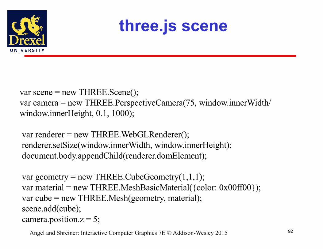
three.js scene
92
var scene = new THREE.Scene();var camera = new THREE.PerspectiveCamera(75, window.innerWidth/ window.innerHeight, 0.1, 1000);
var renderer = new THREE.WebGLRenderer();renderer.setSize(window.innerWidth, window.innerHeight);document.body.appendChild(renderer.domElement);
var geometry = new THREE.CubeGeometry(1,1,1);var material = new THREE.MeshBasicMaterial({color: 0x00ff00});var cube = new THREE.Mesh(geometry, material);scene.add(cube);camera.position.z = 5;
Angel and Shreiner: Interactive Computer Graphics 7E © Addison-Wesley 2015
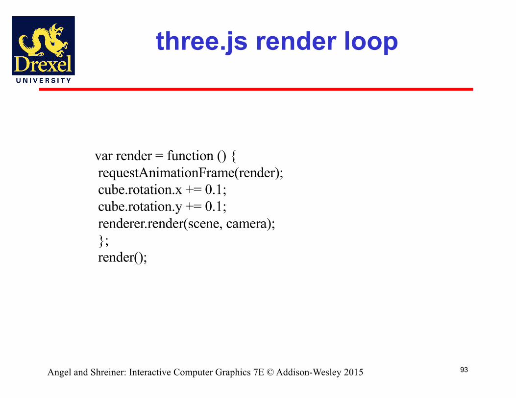
three.js render loop
93
var render = function () {requestAnimationFrame(render);cube.rotation.x += 0.1;cube.rotation.y += 0.1;renderer.render(scene, camera);};render();
Angel and Shreiner: Interactive Computer Graphics 7E © Addison-Wesley 2015