hiblow maintenance guide - septic solutions
TRANSCRIPT

MAINTENANCE GUIDEMAINTENANCE GUIDE

Introduction
We thank you very much purchasing our TECHNO TAKATSUKIHIBLOW air pumps. The introduction of the first HIBLOW pump
was over twenty years ago. More than 3 million HIBLOW pumps
have now been produced and found widespread applications. This
guide book is explained comprehensible as everyone can repair
easily. Can be useful when repairing by all means. Also, please
utilize our maintenance tools for replacement.
What is ISO 9001?
In 1987, the International Organization for Standardization (ISO)
established its ISO 9000 standards. These internationally approved
standards provide specifications not for products but for quality-
assurance systems. ISO 9000 consists of three separate standards:
ISO 9001, 9002, and 9003. Of these, ISO 9001 is the most rigorous,
encompassing points ranging from design control to after-sales
service. To qualify for an ISO 9001 certificate, applicants must first
pass in-company, customer, and third-party audits. After receiving
ISO 9001 certification, regular checks are then conducted to ensure
that the company maintains the required standards. In addition,
management policies on product quality are documented and checked
against actual practice throughout the entire organization. In essence,
the ISO 9001 standard certifies that a company has not only
established an outstanding quality-control record, but has also proven
capable of sustaining this record.
The Product Liability Law
Japan's Product Liability Law was introduced in July 1995 in
response to the increasing difficulty consumers were having in
evaluating the quality of high-technology products and in claiming
damages associated with product defects. With the Product Liability
Law making it easier for customers to claim damages, manufacturers
must now assign a higher priority to quality control.At Techno
Takatsuki Co., Ltd., our response to the above developments was to
create a program that ensured our products were in compliance with
the Product Liability Law. At the same time, we implemented a full
range of safety measures. As a result of these efforts, we received
ISO9001 certification in December 1995, a testament to the high
quality of our product design and manufacturing systems. Despite
this initial success, we remain determined to further improve our
quality-control system, and look forward to the support of our
customers as Techno Takatsuki continues to evolve in years to come.
1
Contents
Contents
● When performing operation, be sure to unplug the pump unit first.
● When performing the replacement work, the pump body may be still hot and you may get burnt. Therefore, wait until the pump has been allowed to cool.
● Never carry the pump by the filter cover.
! CAUTION
Caution for Maintenance
Introduction …………………………………… Back of cover
What is ISO 9001? …………………………… Back of cover
Table of Contents …………………………………………… 1
Caution for Maintenance …………………………………… 1
Maintenance tools …………………………………………… 2
Your Warranty………………………………………………… 2
GJ-L Series ………………………………………………… 3
Replacing the Chamber Block ……………………… 4
Replacing the Electromagnet………………………… 8
GJ-L Series ………………………………………………… 43
GJ-H Series ………………………………………………… 44
HP Series …………………………………………………… 46
Trouble Shooting …………………………………………… 48
Precautions for use ………………………………………… 49
HP Series …………………………………………………… 17
Filter Cleaning and Replacement ………………… 17
Removing Upper Housing ………………………… 18
HP-10/20 ………………………………………………… 19
Replacing the Chamber Block……………………… 20
HP-30/40/50……………………………………………… 22
Replacing the Chamber Block……………………… 23
HP-10~50 Replacing the Electromagnet…………… 25
HP-60/80 ………………………………………………… 27
Replacing the Chamber Block……………………… 28
Replacing the Electromagnet ……………………… 32
HP-100/120 ……………………………………………… 34
Replacing the Chamber Block……………………… 35
Replacing the Electromagnet ……………………… 41
GJ-H Series ………………………………………………… 10
Replacing the Chamber Block……………………… 11
Introduction
List of Spare Parts
Trouble Shooting Guide
HP Series
GJ-L Series
GJ-H Series

2
Maintenance
tool/Your
Warranty
Maintenance tools
Your Warranty
q Screw Driver
w 5.5A each side wrench (3A wrench)
e 7A each side wrench (4A wrench)
r 8A each side wrench (5A wrench)
t Box Driver Handle
q
tw
e
r
With a carring case.
1. Please check a warranty card is supplied and make sure not to lose it.
There is a possibility of expense even though the pump
is under warranty. Read the warranty card carefully.
2. We provide a seven-year guarantee on all spare parts even if the pump go out
of production.
3. Please make an inquiry about a failure of the pump. Here is a number for
customer inquiries.
TECHNO TAKATSUKI CO., LTD.8-16 HATCHO-NISHIMACHI, TAKATSUKI, OSAKA, 569-0095 JAPAN
TEL : 81–726–84–0805
A year warranty period.
3
GJ-
L
GJ-L
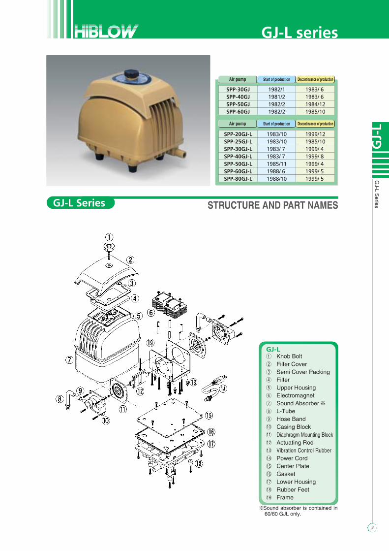
SeriesSTRUCTURE AND PART NAMES
GJ-Lq Knob Boltw Filter Covere Semi Cover Packingr Filtert Upper Housingy Electromagnetu Sound Absorber ei L-Tubeo Hose Band!0 Casing Block!1 Diaphragm Mounting Block!2 Actuating Rod!3 Vibration Control Rubber!4 Power Cord!5 Center Plate!6 Gasket!7 Lower Housing!8 Rubber Feet
SPP-30GJ 1982/1 1983/ 6 SPP-40GJ 1981/2 1983/ 6 SPP-50GJ 1982/2 1984/12SPP-60GJ 1982/2 1985/10
SPP-20GJ-L 1983/10 1999/12SPP-25GJ-L 1983/10 1985/10SPP-30GJ-L 1983/ 7 1999/ 4 SPP-40GJ-L 1983/ 7 1999/ 8 SPP-50GJ-L 1985/11 1999/ 4 SPP-60GJ-L 1988/ 6 1999/ 5 SPP-80GJ-L 1988/10 1999/ 5
Air pump Start of production Discontinuance of production
Air pump Start of production Discontinuance of production
!9 Frame
GJ-L series
GJ-L Series
eSound absorber is contained in60/80 GJL only.

4
GJ-L
Replacing
theC
hamber
Block
STEP1
STEP1Remove the knob bolt. (or truss screw)
STEP2
STEP2Remove the filter cover and the filter.
STEP3
STEP3Remove the bolts from the four corners.Turn the pump up side down.Use 8.0mm each side wrench.
STEP4
STEP4According to the photo, use a screwdriver to pryopen upper and lower housing.If it is difficult to remove it due to the heavilystuck internal packing, insert the tip of ascrewdriver into the clearance between theexhaust nozzle and the upper housing.Remove the sound absorber. (60/80GJL)
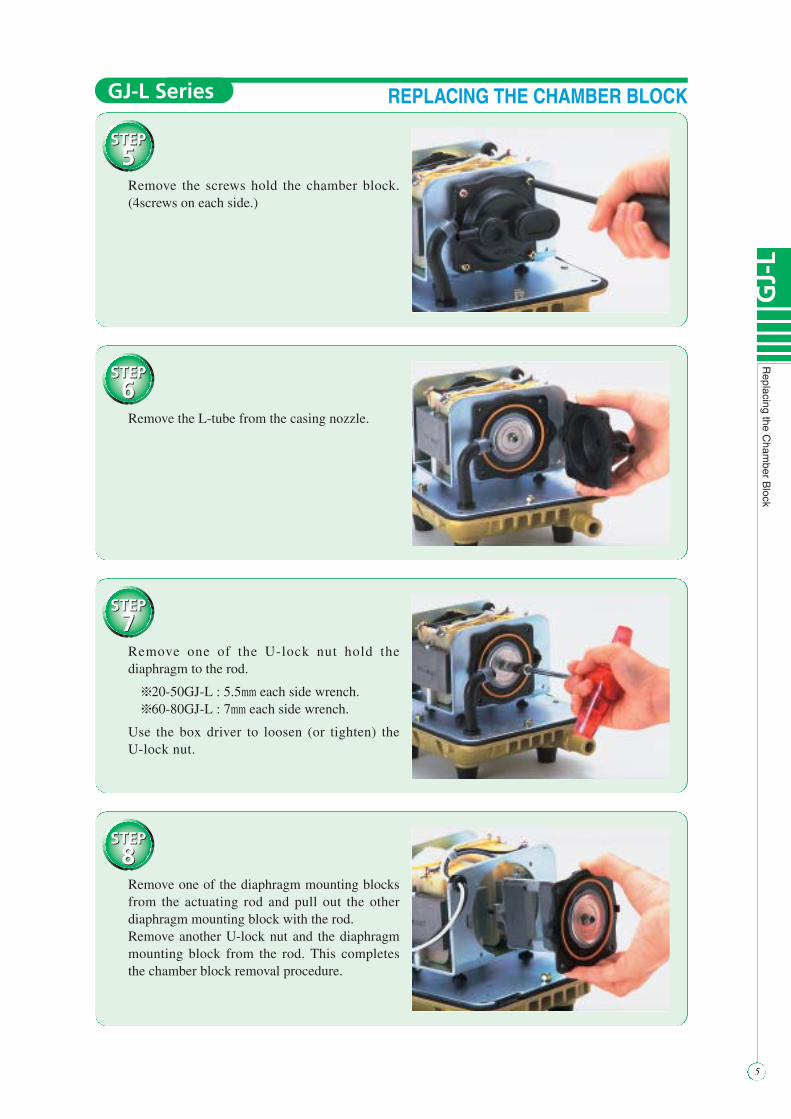
REPLACING THE CHAMBER BLOCKGJ-L Series
STEP5
STEP5Remove the screws hold the chamber block.(4screws on each side.)
STEP6
STEP6Remove the L-tube from the casing nozzle.
STEP7
STEP7Remove one of the U-lock nut hold thediaphragm to the rod.
e20-50GJ-L : 5.5mm each side wrench.e60-80GJ-L : 7mm each side wrench.
Use the box driver to loosen (or tighten) theU-lock nut.
STEP8
STEP8Remove one of the diaphragm mounting blocksfrom the actuating rod and pull out the otherdiaphragm mounting block with the rod.Remove another U-lock nut and the diaphragmmounting block from the rod. This completesthe chamber block removal procedure.
5
GJ-
L
Replacing
theC
hamber
Block
REPLACING THE CHAMBER BLOCKGJ-L Series

6
GJ-L
Replacing
theC
hamber
Block
STEP1
STEP1Install a new diaphragm mounting block on theactuating rod. Set the actuating rod in line withgroove and tighten U-lock nut.• Use new U-lock nut and washer only that come asreplacement parts to prevent a damage of the pump.
STEP2
STEP2Insert the actuating rod in accordance with thegap of frame.
STEP3
STEP3Secure the diaphragm mounting block on otherside and tighten with washer and U-lock nutusing the box driver.Make sure the gaps between the actuating rodand electromagnet are even.
STEP4
STEP4Connect L-tube to the casing block and securethe casing with the screws. (4screws on each side)Install the casing block at the same way.Install the sound absorber. (60/80GJL).
REPLACING THE CHAMBER BLOCKGJ-L Series

STEP5
STEP5
Place upper housing back on body. (Be extremelycareful about the cord bushing.)If the pump makes an abnormal noise, this may besign of improper positioning of the cord bushing.Tighten each of four bolts gradually and uniformlytill they are firmly fastened.Set the pump back in upright position and replacethe filter.
STEP6
STEP6Replace the filter.• Remove all dust that collected on pad.If it is heavily soiled, use a neutral detergent to wash it,rinse it with water and dry it well out of direct sunlightbefore reinstalling.
STEP7
STEP7Place the filter cover back on properly.
STEP8
STEP8Secure with a knob bolt.(or truss screw.)Please check whether the pump sounds unusualand the amount of discharged air is greatlyreduced.
7
GJ-
L
Replacing
theC
hamber
Block
REPLACING THE CHAMBER BLOCKGJ-L Series

8
GJ-L
Replacing
theE
lectromagnet
STEP1
STEP1Cut the wires from the terminals on theelectromagnet with the nippers.• It is recommended that you make a note of the wiring.
STEP2
STEP2A status indication.(Same lead wires and connections are cut.)
STEP3
STEP3Remove the nuts with the 7mm wrench.
STEP4
STEP4Pull out the electromagnets from the body.
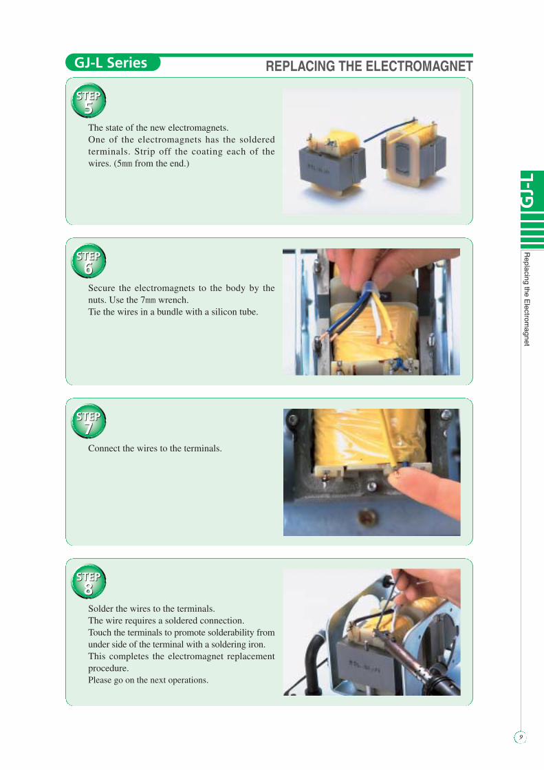
REPLACING THE ELECTROMAGNETGJ-L Series
STEP5
STEP5The state of the new electromagnets.One of the electromagnets has the solderedterminals. Strip off the coating each of thewires. (5mm from the end.)
STEP6
STEP6Secure the electromagnets to the body by thenuts. Use the 7mm wrench.Tie the wires in a bundle with a silicon tube.
STEP7
STEP7Connect the wires to the terminals.
STEP8
STEP8Solder the wires to the terminals.The wire requires a soldered connection.Touch the terminals to promote solderability fromunder side of the terminal with a soldering iron.This completes the electromagnet replacementprocedure.Please go on the next operations.
REPLACING THE ELECTROMAGNET
9
GJ-
L
Replacing
theE
lectromagnet
GJ-L Series

STRUCTURE AND PART NAMES
GJ-Hq Knob Boltw Filter Covere Semi Cover Packingr Filtert Sound Absorbery Casing Blocku Diaphragm Mounting Blocki Actuating Rodo Electromagnet!0 SM Switch Holder!1 SM Switch Bar!2 Power Cord!3 Center Plate!4 Hose Clip!5 L-Tube!6 Vibration Control Rubber!7 Gasket!8 Lower Housing!9 Rubber Feet@0 Upper Housing
SPP-60GJ-H 1986/ 6 1992/ 6 SPP-70GJ-H 1985/11 1991/ 4 SPP-80GJ-H 1985/11 1992/ 6 SPP-100GJ-H 1985/11 1999/12SPP-120GJ-H 1985/11 1999/11SPP-150GJ-H 1987/ 7 —SPP-200GJ-H 1987/ 7 —
Air pump Start of production Discontinuance of production
@1 Stay@2 Frame
10
GJ-H
GJ-H
Series
GJ-H series
GJ-H Series

11
GJ-
H
Replacing
theC
hamber
Block
STEP1
STEP1Remove the knob bolt.
STEP2
STEP2Remove the filter cover.
STEP3
STEP3Remove the filter.
STEP4
STEP4Turn the pump up side down.Remove the bolts from the four corners.Use 8mm each side wrench.
REPLACING THE CHAMBER BLOCKGJ-H Series

STEP5
STEP5Use a screwdriver to pry open upper and lowerhousings as shown in photo.
STEP6
STEP6Remove the sound absorber.
STEP7
STEP7Remove the screws hold the chamber block.(4screws on each side.)
STEP8
STEP8Remove the L-tube from the casing nozzle.
12
GJ-H
Replacing
theC
hamber
Block
REPLACING THE CHAMBER BLOCKGJ-H Series

13
GJ-
H
Replacing
theC
hamber
Block
STEP9
STEP9Remove the U-lock nut securing diaphragmfrom only one side.
150/200GJL : 7mm each side wrench.
Use the box driver to tighten (or loosen) theU-lock nut.
STEP10
STEP10
Remove one of the diaphragm mounting blockfrom the rod, and pull out the other diaphragmmounting block from the pump body with the rod.Remove the other diaphragm mounting blockfrom the rod.This completes the chamber block removalprocedure.
REPLACING THE CHAMBER BLOCKGJ-H Series
STEP1
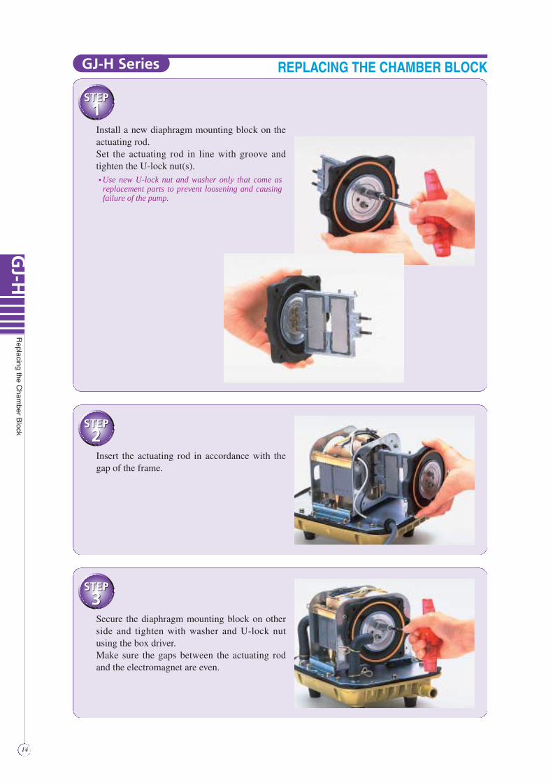
STEP1Install a new diaphragm mounting block on theactuating rod.Set the actuating rod in line with groove andtighten the U-lock nut(s).• Use new U-lock nut and washer only that come asreplacement parts to prevent loosening and causingfailure of the pump.
STEP2
STEP2Insert the actuating rod in accordance with thegap of the frame.
STEP3
STEP3Secure the diaphragm mounting block on otherside and tighten with washer and U-lock nutusing the box driver.Make sure the gaps between the actuating rodand the electromagnet are even.
14
GJ-H
Replacing
theC
hamber
Block
REPLACING THE CHAMBER BLOCKGJ-H Series
15
GJ-
H
Replacing
theC
hamber
Block
STEP4
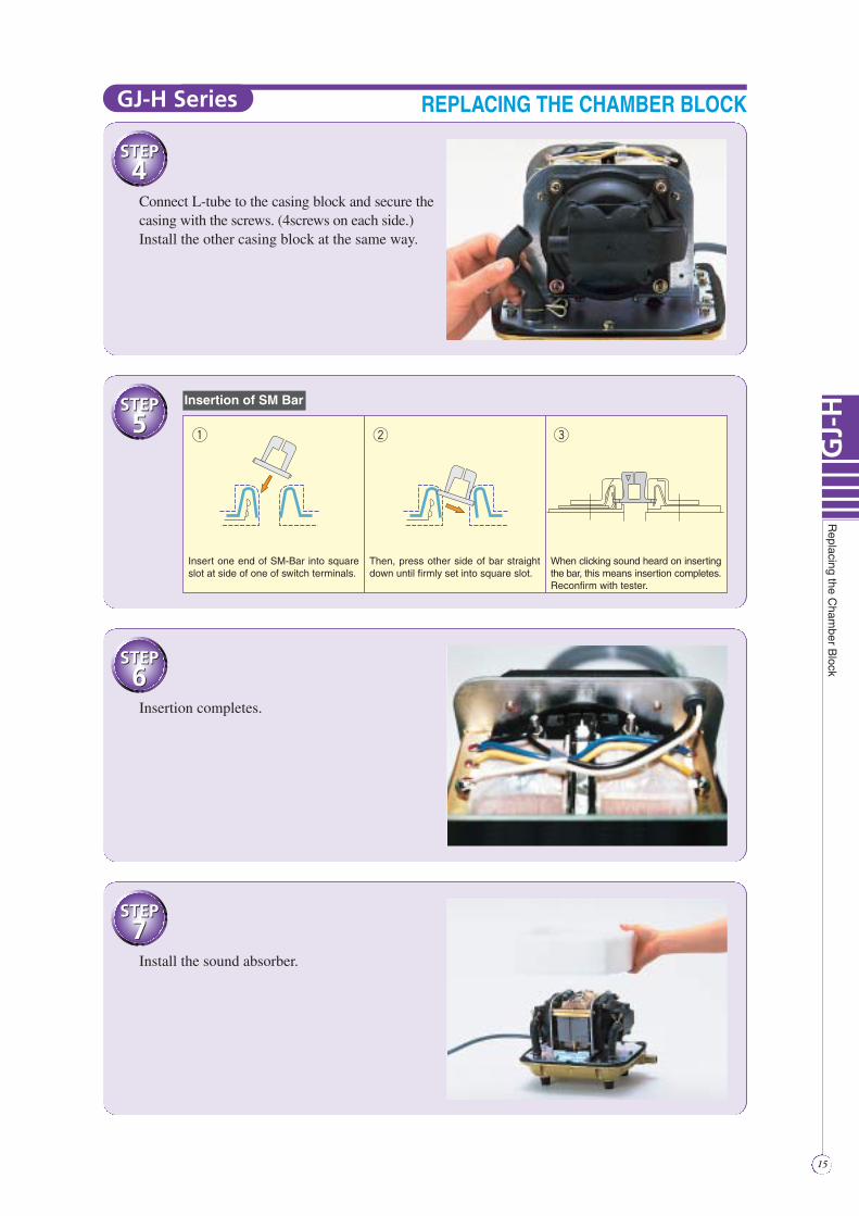
STEP4Connect L-tube to the casing block and secure thecasing with the screws. (4screws on each side.)Install the other casing block at the same way.
STEP5
STEP5
q w e
Insert one end of SM-Bar into square slot at side of one of switch terminals.
Then, press other side of bar straight down until firmly set into square slot.
When clicking sound heard on inserting the bar, this means insertion completes. Reconfirm with tester.
STEP6
STEP6Insertion completes.
STEP7
STEP7Install the sound absorber.
Insertion of SM Bar
REPLACING THE CHAMBER BLOCKGJ-H Series

STEP8
STEP8Place the upper housing back on body.(Be extremely careful about the cord bushing.)If the pump makes an abnormal noise, this maybe sign of improper positioning of the cordbushing.
STEP9
STEP9Turn the pump body upside down and tightenbolts.
STEP10
STEP10
Replace the filter pad.• Remove all dust that collected on pad.
• If it heavily soiled, use a neutral detergent to wash it ,rinse it with water, and dry it well out of direct sunlightbefore reinstalling.
STEP11
STEP11
Place the filter cover back on properly.Secure it with the Knob bolt.Please check whether the pump sounds unusualand the amount of discharged air is greatlyreduced.
16
GJ-H
Replacing
theC
hamber
Block
REPLACING THE CHAMBER BLOCKGJ-H Series
17
HP
Rem
ovingupper
housing
STEP1
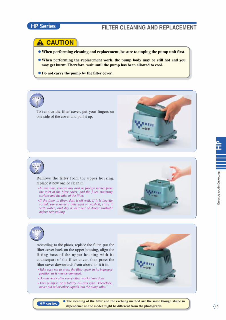
STEP1To remove the filter cover, put your fingers onone side of the cover and pull it up.
STEP2
STEP2Remove the filter from the upper housing,replace it new one or clean it.• At this time, remove any dust or foreign matter fromthe inlet of the filter cover, and the filter mountingsurface and the inlet of the filter.
• If the filter is dirty, dust it off well. If it is heavilysoiled, use a neutral detergent to wash it, rinse itwith water, and dry it well out of direct sunlightbefore reinstalling.
STEP3
STEP3
According to the photo, replace the filter, put thefilter cover back on the upper housing, align thefitting boss of the upper housing with itscounterpart of the filter cover, then press thefilter cover downwards from above to fit it in.• Take care not to press the filter cover in its improperposition as it may be damaged.
• Do this work after every other works have done.
• This pump is of a totally oil-less type. Therefore,never put oil or other liquids into the pump inlet.
● When performing cleaning and replacement, be sure to unplug the pump unit first.
● When performing the replacement work, the pump body may be still hot and you may get burnt. Therefore, wait until the pump has been allowed to cool.
● Do not carry the pump by the filter cover.
! CAUTION
● The cleaning of the filter and the exchang method are the same though shape in
dependence on the model might be different from the photograph.HP series
FILTER CLEANING AND REPLACEMENTHP Series
18
HP
Rem
ovingupper
housing
STEP1
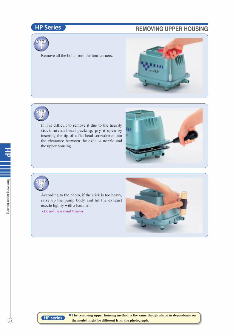
STEP1Remove all the bolts from the four corners.
STEP2
STEP2If it is difficult to remove it due to the heavilystuck internal seal packing, pry it open byinserting the tip of a flat-head screwdriver intothe clearance between the exhaust nozzle andthe upper housing.
STEP3
STEP3According to the photo, if the stick is too heavy,raise up the pump body and hit the exhaustnozzle lightly with a hammer.• Do not use a metal hammer.
The removing upper housing method is the same though shape in dependence on
the model might be different from the photograph.HP series
HP Series REMOVING UPPER HOUSING
19
HP
HP
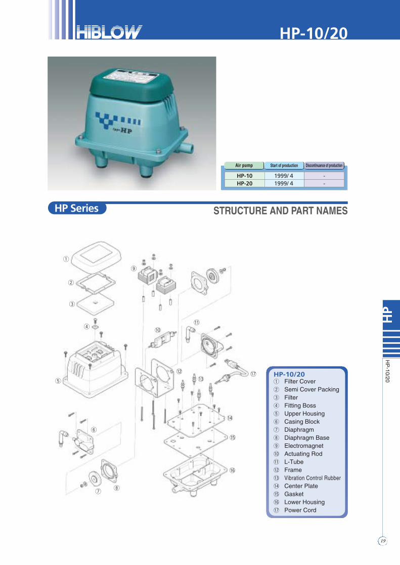
-10/20HP-10/20q Filter Coverw Semi Cover Packinge Filterr Fitting Bosst Upper Housingy Casing Blocku Diaphragmi Diaphragm Baseo Electromagnet!0 Actuating Rod!1 L-Tube!2 Frame!3 Vibration Control Rubber!4 Center Plate!5 Gasket!6 Lower Housing!7 Power Cord
HP-10 1999/ 4 -HP-20 1999/ 4 -
Air pump Start of production Discontinuance of production
q
w
e
r
t
y
ui
o
!0
!1
!2
!3
!4
!5
!6
!7
STRUCTURE AND PART NAMES
HP-10/20
HP Series

20
HP
Replacing
theC
hamber
Block
STEP1
STEP1Remove the upper housing according to thepicture on page 17.Remove the L-tube from the casing nozzle.Remove the installation screws of the chamberblock. (4 screws on each side.)Remove the casing block.
STEP2
STEP2Remove the U-lock nut.• Use the box driver to loosen (or tighten) the U-locknut.
STEP3
STEP3Remove one of the diaphragm mounting blocksfrom the actuating rod, and pull out the otherdiaphragm mounting block with the rod fromthe pump body.Remove another U-lock nut and the diaphragmmouting block from the rod.This completes the chamber block removalprocedure.
● When performing the replacement, be sure to unplug the pump unit first.● Replace the diaphragms and the valves with new ones regularly (every one year or one and half years) in order to maintain their initial performance.● For chamber block replacement, be sure to change both chamber blocks at the same time.● The actuating rod employs powerful permanent magnets. Therefore, be sure to remove
your watch and precision machine before starting the work as it may fail due to their strong magnetic force.
● Do not put the actuating rod close to a magnetic card, a magnetic disk or any other magnetic media as their data may be lost.
! CAUTION
REMOVAL OF THE CHAMBER BLOCKS
REPLACING THE CHAMBER BLOCKHP-10/20

STEP4
STEP4Install a new diaphragm mouting block on theactuating rod.Set the actuating rod in line with groove andtighten the U-lock nut.• Use new U-lock nut and washer only that come asreplacement parts to prevent loosening and causingfailure of the pump.
STEP5
STEP5Insert the actuating rod in accordance with thegap of the frame.Secure the diaphragm mounting block on otherside and tighten with washer and U-lock nutusing the box driver.Make sure the gaps between the actuating rodand the electromagnet are even.
STEP6
STEP6Connect L-tube to the casing block. Secure thecasing block with the screws. (4screws on eachside.)Install the other casing block at the same way.
STEP7
STEP7Secure the upper housing with the bolts.Then, replace the filter and filter cover on it.(See page17 “FILTER CLEANING ANDREPLACEMENT”)
FITTING THE CHAMBER BLOCKS
REPLACING THE CHAMBER BLOCK
21
HP
Replacing
theC
hamber
Block
HP-10/20

HP-30 1998/ 8 —HP-40 1998/ 8 —HP-50 1998/12 —
Air pump Start of production Discontinuance of production
HP-30/40/50q Filter Coverw Semi Cover Packinge Filterr Fitting Bosst Upper Housingy Sound Absorber (HP50)u Casing Blocki Diaphragm Ringo Diaphragm!0 Diaphragm Base!1 Electromagnet!2 Actuating Rod!3 L-Tube!4 Frame!5 Vibration Control Rubber!6 Center Plate!7 Gasket!8 Lower Housing!9 Power Cord
q
w
e
r
t
y
u
io
!0
!1
!2!3
!4
!5
!6
!7
!8
!9
STRUCTURE AND PART NAMES
22
HP
HP
-30/40/50
HP-30/40/50
HP Series

23
HP
Replacing
theC
hamber
Block
STEP1
STEP1Remove the upper housing.(See page18)Remove the sound absorber.Remove the four screws hold the chamberblock. (4screws on each side.)Pull out the L-tube from the casing nozzle andremove the casing block on both side.
STEP2
STEP2Remove one of the U-lock nuts hold thediaphragm mounting block to the rod.• Use the box driver to loosen (or tighten) the U-locknut.
STEP3
STEP3
Remove one of the diaphragm mounting blockfrom the rod, and pull out the other diaphragmmounting block with the rod from the pump body.Remove another U-lock nut and the diaphragmmounting block from the rod.This completes the chamber block removalprocedure.
● Be sure to unplug the pump unit.● Replace the diaphragms and the valves with new ones at least once a year or one and
a half years in order to maintain their initial performance.● For chamber block replacement, be sure to change both chamber blocks at the same time.● The rod employs powerful permanent magnets. Therefore, be sure to remove your watch
and precision machine before starting the work as it may fail due to their strong magnetic force.
● Do not put the actuating rod close to a magnetic card, a magnetic disk or any other magnetic media as their data may be lost.
! CAUTION
REPLACING THE CHAMBER BLOCK
REMOVAL OF THE CHAMBER BLOCKS
HP-30/40/50

STEP4
STEP4Install a new diaphragm mounting block on theactuating rod.Set the actuating rod in line with groove andtighten the U-lock nut with the box driver.• Use new U-lock nut and washer only that come asreplacement parts to prevent loosening and causingfailure of the pump.
STEP5
STEP5Insert the actuating rod in accordance with thegap of the frame.Secure the diaphragm mounting block on otherside and tighten with washer and U-lock nutwith the box driver.Make sure the gaps between the actuating rodand the electromagnet are even.
STEP6
STEP6Connect L-tube to the casing block and securethe casing with the screws. (4screws on eachside)Install the other casing block at the same way.
STEP7
STEP7Install the sound absorber. (HP-50)• Be extremely careful not to pinch the SoundAbsorber in the Upper Housing.
Secure the upper housing with the bolts.Then place the filter and filter cover on theupper housing. (See page17 “FILTERCLEANING AND REPLACEMENT”)
24
HP
Replacing
theC
hamber
Block
REPLACING THE CHAMBER BLOCK
FITTING THE CHAMBER BLOCKS
HP-30/40/50

25
HP
Replacing
theE
lectromagnet
STEP1
STEP1Cut the wire from the terminals on theelectromagnet with nippers.• It is recommended that you make a note of thewiring.
STEP2
STEP2Remove the nuts with the box driver.(7mm wrench.)
STEP3
STEP3Pull out electromagnets from the pump body.
● Be sure to unplug the pump unit.● When performing replacement work, the pump body may be still hot and you may get
burnt. Therefore, wait until the pump has been allowed to cool.● Be sure to remove the chamber block and the actuating rod before replacing the
electromagnet.● It is better to let an experienced technician handle the soldering process.
Take precautions against being burnt.● In case of HP-10/20, do the same way of replacing the electromagnet.
! CAUTION
REPLACING THE ELECTROMAGNET
REMOVING THE ELECTROMAGNET
HP-10~50
26
HP
Replacing
theE
lectromagnet
STEP4
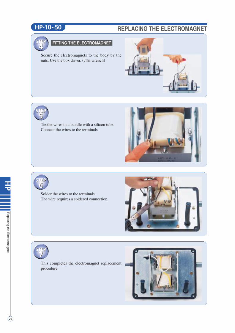
STEP4Secure the electromagnets to the body by thenuts. Use the box driver. (7mm wrench)
STEP5
STEP5Tie the wires in a bundle with a silicon tube.Connect the wires to the terminals.
STEP6
STEP6Solder the wires to the terminals.The wire requires a soldered connection.
STEP7
STEP7This completes the electromagnet replacementprocedure.
HP-10~50 REPLACING THE ELECTROMAGNET
FITTING THE ELECTROMAGNET

27
HP
HP
-60/80
w
!3
y
!7
!4
q
e
r
t
!9
i
o!0
!1
!2
u
!6
!5
!8
@0
@1
@2
HP-60/80q Filter Coverw Semi Cover Packinge Filterr Fitting Bosst Upper Housingy Sound Absorberu Casing Blocki Diaphragm Ringo Diaphragm!0 Diaphragm Base!1 SP Switch!2 Safety Screw!3 Electromagnet!4 Actuating Rod!5 L-Tube!6 Hose Band!7 Frame!8 Vibration Control Rubber!9 Center Plate@0 Gasket@1 Lower Housing@2 Power Cord
HP-60 1995/ 9 —HP-80 1995/ 9 —
Air pump Start of production Discontinuance of production
STRUCTURE AND PART NAMES
HP-60/80
HP Series

28
HP
Replacing
theC
hamber
Block
STEP1
STEP1Remove the Upper Housing.(See page18 “REMOVING UPPER HOUSING”)
STEP2
STEP2Remove the sound absorber.Pull out the L-tube from the casing nozzle.Remove the four screws hold the chamber blockand the casing block on both side.(4screws on each side)
STEP3
STEP3Remove one of the U-lock nuts hold thediaphragm mounting block to the rod.• Use the box driver to loosen (or tighten) the U-locknut.
● Be sure to unplug the pump unit.● Replace the diaphragms and the valves with new ones at least once a year or one and
a half years in order to maintain their initial performance.● For chamber block replacement, be sure to change both chamber blocks at the same time.● The rod employs powerful permanent magnets. Therefore, be sure to remove your watch
and precision machine before starting the work as it may fail due to their strong magnetic force.
● Do not put the actuating rod close to a magnetic card, a magnetic disk or any other magnetic media as their data may be lost.
! CAUTION
REMOVAL OF THE CHAMBER BLOCKS
REPLACING THE CHAMBER BLOCKHP-60/80

STEP4
STEP4
Remove one of the diaphragm mounting blocks from theactuating rod and pull out the other diaphragm mountingblock with the rod and finally, separate the diaphragmmounting block and rod.This completes the chamber block removal procedure.• When pull out the rod, take care not to allow the rod projection toaccidentally hit the lever of the SP switch. If the pump stops automatically,the safety screw must be broken to prevent any further damage to the pump.Be sure all debris is removed from unit. (See Step8)
STEP5
STEP5Install the new diaphragm mounting block onthe actuating rod.• Use new U-lock and washer only that come asreplacement parts to prevent loosening and causingfailure of the pump.
STEP6
STEP6Insert the actuating rod in accordance with thegap of the frame.Secure the diaphragm mounting block on theother side and tighten the U-lock nut with thebox driver.Make sure the gaps between the actuating rodand the electromagnet are even.
STEP7
STEP7Connect L-tube to the casing block and securethe casing with the screws.(4screws on each side)Install the other casing block at the same way.
29
HP
Replacing
theC
hamber
Block
REPLACING THE CHAMBER BLOCK
FITTING THE CHAMBER BLOCKS
HP-60/80
30
HP
Replacing
theC
hamber
Block
STEP8
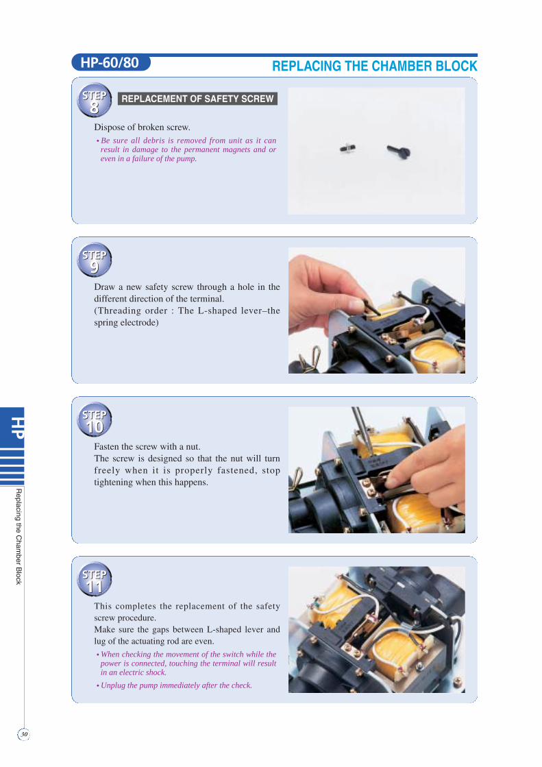
STEP8Dispose of broken screw.• Be sure all debris is removed from unit as it canresult in damage to the permanent magnets and oreven in a failure of the pump.
STEP9
STEP9Draw a new safety screw through a hole in thedifferent direction of the terminal.(Threading order : The L-shaped lever–thespring electrode)
STEP10
STEP10
Fasten the screw with a nut.The screw is designed so that the nut will turnfreely when it is properly fastened, stoptightening when this happens.
STEP11
STEP11
This completes the replacement of the safetyscrew procedure.Make sure the gaps between L-shaped lever andlug of the actuating rod are even.
• When checking the movement of the switch while thepower is connected, touching the terminal will resultin an electric shock.
• Unplug the pump immediately after the check.
REPLACING THE CHAMBER BLOCK
REPLACEMENT OF SAFETY SCREW
HP-60/80
31
HP
Replacing
theC
hamber
Block
STEP12
STEP12
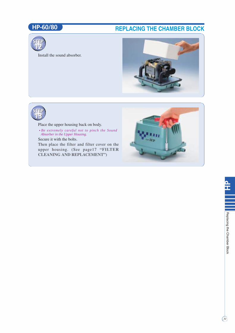
Install the sound absorber.
STEP13
STEP13
Place the upper housing back on body.• Be extremely careful not to pinch the SoundAbsorber in the Upper Housing.
Secure it with the bolts.Then place the filter and filter cover on theupper housing. (See page17 “FILTERCLEANING AND REPLACEMENT”)
REPLACING THE CHAMBER BLOCKHP-60/80

32
HP
Replacing
theE
lectromagnet
STEP1
STEP1Cut the wire from terminals on the electromag-nets with nippers.• It is recommended that you make a note of the wiring.
STEP2
STEP2Undo the frame screws and remove the SPswitch.
STEP3
STEP3Remove the mounting nuts with the box driver.(7mm wrench)Pull out the electromagnets from the pumpbody.
● Be sure to unplug the pump.● When performing replacement work, the pump body may be still hot and you may get
burnt. Therefore, wait until the pump has been allowed to cool.● Be sure to remove the chamber block and the actuating rod before replacing the
electromagnet.● It is better to let an experienced technician handle the soldering process.
! CAUTION
REPLACING THE ELECTROMAGNET
REMOVAL OF ELECTROMAGNET
HP-60/80
STEP4
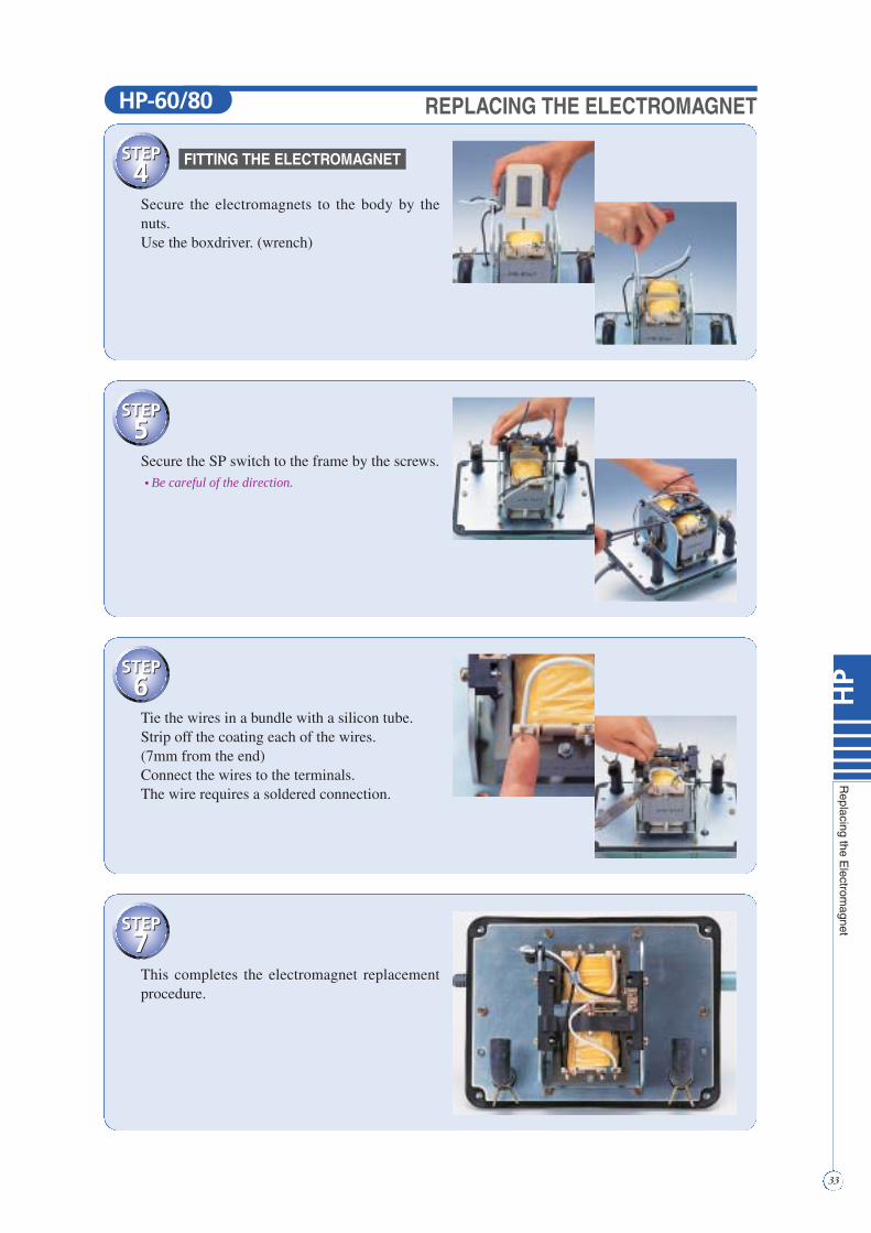
STEP4Secure the electromagnets to the body by thenuts.Use the boxdriver. (wrench)
STEP5
STEP5Secure the SP switch to the frame by the screws.• Be careful of the direction.
STEP6
STEP6Tie the wires in a bundle with a silicon tube.Strip off the coating each of the wires.(7mm from the end)Connect the wires to the terminals.The wire requires a soldered connection.
STEP7
STEP7This completes the electromagnet replacementprocedure.
REPLACING THE ELECTROMAGNET
FITTING THE ELECTROMAGNET
33
HP
Replacing
theE
lectromagnet
HP-60/80

w
y
q
e
r
t
!9
@0
@1
@2@3
@4
@5
@6
@7
!1
!2!3
!4
!5
!6
!7
u
!8
!0
i
o
HP-100/120q Filter Coverw Semi Cover Packinge Filterr Fitting Bosst Upper Housingy Sound Absorber (Lap)u Casing Block Ai Valve Chamber Packingo Casing Block B!0 Valve!1 Diaphragm Ring!2 Diaphragm!3 Diaphragm Base!4 Frame Cover!5 SP Switch!6 Safety Screw!7 Electromagnet!8 Actuating Rod!9 L-Tube@0 Hose Band@1 Frame@2 Vibration Control Rubber@3 Center Plate@4 Gasket@5 Sound Absorber (Filter)@6 Lower Housing@7 Power Cord
HP-100 1997/10 —HP-120 1997/10 —
Air pump Start of production Discontinuance of production
STRUCTURE AND PART NAMES
34
HP
HP
-100/120
HP-100/120
HP Series
35
HP
Replacing
theC
hamber
Block
STEP1
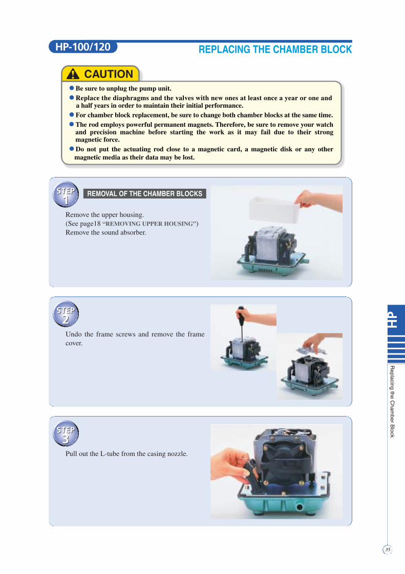
STEP1Remove the upper housing.(See page18 “REMOVING UPPER HOUSING”)Remove the sound absorber.
STEP2
STEP2Undo the frame screws and remove the framecover.
STEP3
STEP3Pull out the L-tube from the casing nozzle.
● Be sure to unplug the pump unit.● Replace the diaphragms and the valves with new ones at least once a year or one and
a half years in order to maintain their initial performance.● For chamber block replacement, be sure to change both chamber blocks at the same time.● The rod employs powerful permanent magnets. Therefore, be sure to remove your watch
and precision machine before starting the work as it may fail due to their strong magnetic force.
● Do not put the actuating rod close to a magnetic card, a magnetic disk or any other magnetic media as their data may be lost.
! CAUTION
REPLACING THE CHAMBER BLOCK
REMOVAL OF THE CHAMBER BLOCKS
HP-100/120

STEP4
STEP4Remove the four screws hold the chamber blockand the casing block on both side.(4screws on each side)• Casing block is separated into Casing A (Exhaustpart side) and Casing B (Air valve side).
STEP5
STEP5Remove one of the U-lock nuts hold thediaphragm mounting block to the rod.• Use the box driver to loosen (or tighten) the U-locknut.
STEP6
STEP6
Remove one of the diaphragm mounting blocksfrom the actuating rod and pull out the otherdiaphragm mounting block with the rod andfinally, separate the diaphragm mounting blockand the rod.• When pulling out the rod, take care not to catch the rod projection on the lever ofthe SP switch.
• If the pump stops automatically, the safety screw must be broken to prevent anyfurther damage to the pump. Be sure all debris is removed from unit. (See Step 15)
STEP7
STEP7
36
HP
Replacing
theC
hamber
Block
In case of replacing the diaphragm mountingblock, skip some steps, and move straight fromstep 12.Remove the diaphragm ring from thediaphragm, and then, the diaphragm from thediaphragm base.
REPLACING THE CHAMBER BLOCK
REPLACING THE DIAPHRAGM
HP-100/120

37
HP
Replacing
theC
hamber
Block
STEP8
STEP8Install a new diaphragm and a diaphragm ring inthe diaphragm base.• Take care not to create any clearance between them.
STEP9
STEP9In case of replacing the diaphragm mountingblock, skip some steps, and move straight fromstep 12.Remove the valves from the casing B.• If it is difficult to separate them, insert the tip of aflatblade screwdriver into the clearance.
• Pull out the valves as they can be removed withfacility.
STEP10
STEP10
Insert each new valve into the center hole ofvalve seat, and secure them by pulling with theradio pliers.• When reinstalling the valves, make sure they arecorrectly fitted the exhaust and intake side.
STEP11
STEP11
Cut away the respective pulling ends withscissors or nippers.• Leave each of the thick parts.
REPLACING THE CHAMBER BLOCK
REPLACING THE VALVE
HP-100/120

STEP12
STEP12
Set the actuating rod in line with groove andtighten U-lock nut with the box driver.• Use new U-lock nut and washer only that come asreplacement parts to prevent loosening and causingfailure of the pump.
STEP13
STEP13
Insert the actuating rod in accordance with thegap of the frame.Secure the diaphragm mounting block on theother side and tighten with washer and U-locknut with the box driver.Make sure the gaps between the actuating rodand the electromagnet are even.
STEP14
STEP14
Connect L-tube to the casing block and securethe casing with the screws.(4screws on each side)Install the other casing block at the same way.
STEP15
STEP15
Dispose of broken screw. Be sure all debris isremoved from unit as it can result in damage tothe permanent magnets and or even in a failureof the pump.
38
HP
Replacing
theC
hamber
Block
FITTING CHAMBER BLOCKS
REPLACEMENT OF SAFETY SCREW
REPLACING THE CHAMBER BLOCKHP-100/120
39
HP
Replacing
theC
hamber
Block
STEP16
STEP16
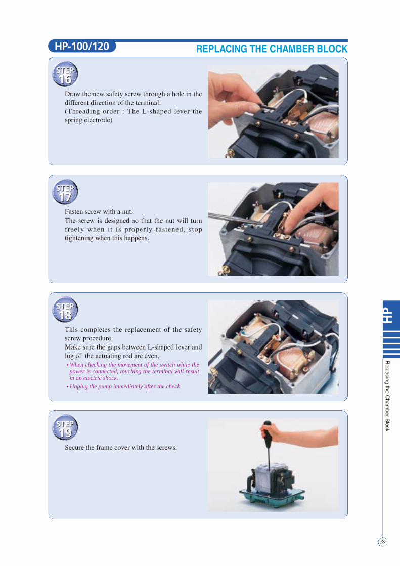
Draw the new safety screw through a hole in thedifferent direction of the terminal.(Threading order : The L-shaped lever-thespring electrode)
STEP17
STEP17
Fasten screw with a nut.The screw is designed so that the nut will turnfreely when it is properly fastened, stoptightening when this happens.
STEP18
STEP18
This completes the replacement of the safetyscrew procedure.Make sure the gaps between L-shaped lever andlug of the actuating rod are even.• When checking the movement of the switch while thepower is connected, touching the terminal will resultin an electric shock.
• Unplug the pump immediately after the check.
STEP19
STEP19
Secure the frame cover with the screws.
REPLACING THE CHAMBER BLOCKHP-100/120
STEP20
STEP20
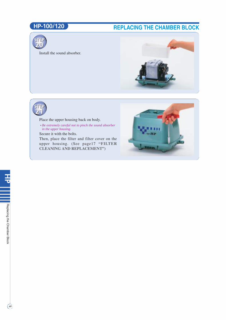
Install the sound absorber.
STEP21
STEP21
Place the upper housing back on body.• Be extremely careful not to pinch the sound absorberin the upper housing.
Secure it with the bolts.Then, place the filter and filter cover on theupper housing. (See page17 “FILTERCLEANING AND REPLACEMENT”)
40
HP
Replacing
theC
hamber
Block
REPLACING THE CHAMBER BLOCKHP-100/120
41
HP
Replacing
theE
lectromagnet
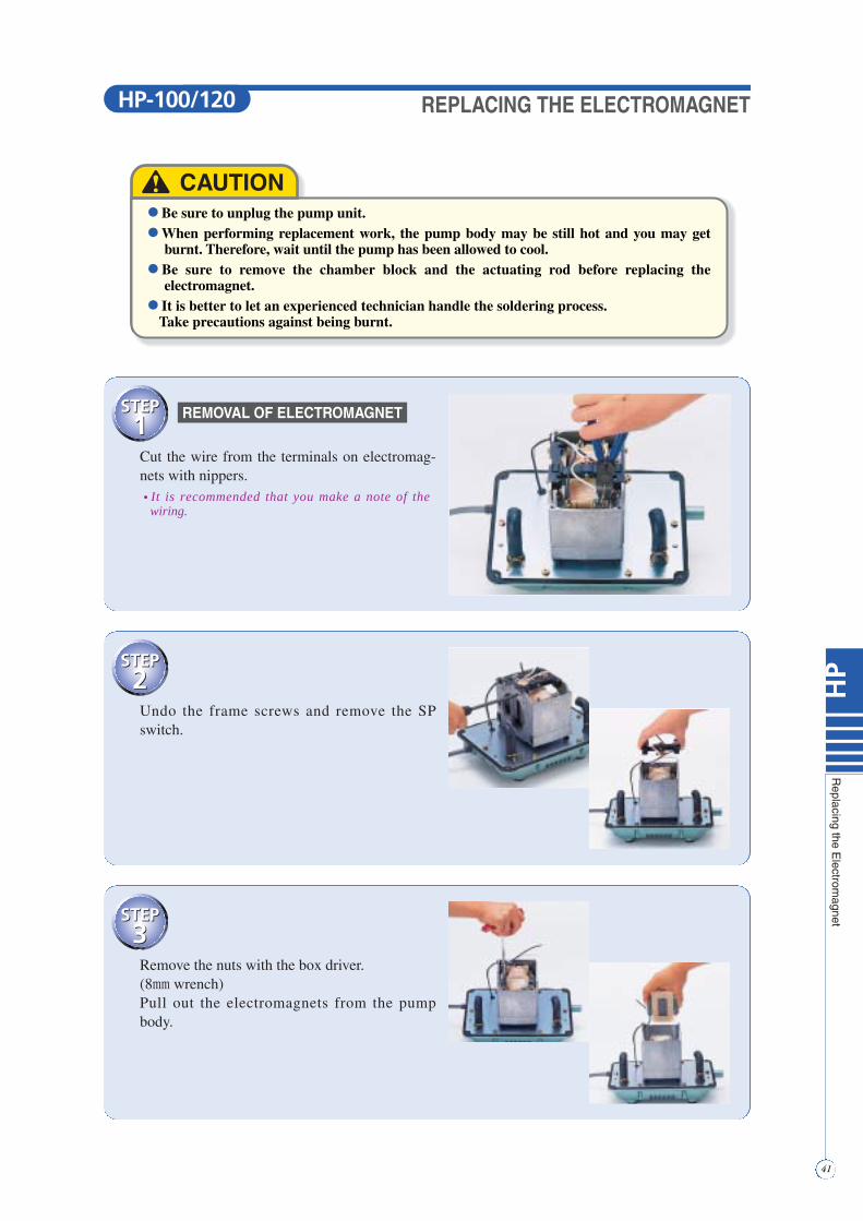
● Be sure to unplug the pump unit.● When performing replacement work, the pump body may be still hot and you may get
burnt. Therefore, wait until the pump has been allowed to cool.● Be sure to remove the chamber block and the actuating rod before replacing the
electromagnet.● It is better to let an experienced technician handle the soldering process.
Take precautions against being burnt.
! CAUTION
STEP1
STEP1Cut the wire from the terminals on electromag-nets with nippers.• It is recommended that you make a note of thewiring.
STEP2
STEP2Undo the frame screws and remove the SPswitch.
STEP3
STEP3Remove the nuts with the box driver.(8mm wrench)Pull out the electromagnets from the pumpbody.
REPLACING THE ELECTROMAGNET
REMOVAL OF ELECTROMAGNET
HP-100/120
42
HP
Replacing
theE
lectromagnet
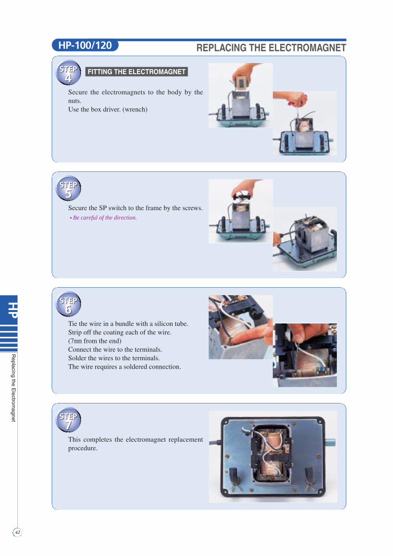
STEP4
STEP4Secure the electromagnets to the body by thenuts.Use the box driver. (wrench)
STEP5
STEP5Secure the SP switch to the frame by the screws.• Be careful of the direction.
STEP6
STEP6Tie the wire in a bundle with a silicon tube.Strip off the coating each of the wire.(7mm from the end)Connect the wire to the terminals.Solder the wires to the terminals.The wire requires a soldered connection.
STEP7
STEP7This completes the electromagnet replacementprocedure.
REPLACING THE ELECTROMAGNET
FITTING THE ELECTROMAGNET
HP-100/120

43
GJ-Lseries
ListofSpare
Parts
GJ-L SERIES PartsLists
RodFor GJ-L
Parts Name Model Order CodeDiaphragm Mounting Block
For GJ-L 20GJ-L
30GJ-L40GJ-L
50GJ-L
60GJ-L80GJ-L
25PD000020
40PD000020
60PD000010
80PD000030
Parts Name Model Order Code
CONTENTS
2pcs./set
DiaphragmDiaphragm RingDiaphragm BaseU-lock Nut / Washer
CONTENTS
1pcs./set
Magnet / Rod FrameCenter Screw (United)U-lock Nut / Washer
FilterFor GJ-L
20GJ-L
30GJ-L
40GJ-L
50GJ-L
60GJ-L
80GJ-L
PA20EML100
PA30EML100
PA40EML100
PA60EMG100
PA60EML100
PA80EML100
Casing BlockFor GJ-L 20GJ-L
30GJ-L40GJ-L
50GJ-L
60GJ-L80GJ-L
25PK000020
40PK000020
60PK000010
80PK000030
20GJ-L
30GJ-L40GJ-L
50GJ-L
60GJ-L80GJ-L
25PC000020
40PC000020
60PC000010
80PC000030
20GJ-L
30GJ-L
40GJ-L
50GJ-L
20PR000010
30PR000020
40PR000020
60PR000010
60GJ-L80GJ-L 80PR000030
CONTENTS
2pcs./set
CasingValve / ValveChamber Packing
Filter CoverFor GJ-L 20~50GJ-L
(silver col.) FC03000200
60GJ-L80GJ-L
(gold col.)FC03000400
GJ-L FI09000100
Semi Cover PackingFor GJ-L
GJ-L
Old model1pcs./set
FP00200100
New model2pcs./set
FP00200101
Upper HousingFor GJ-L 20~50GJ-L
(silver col.)
60GJ-L80GJ-L
(gold col.)
HUPL020SI0
HUPL080GO0
GasketFor GJ-L
GJ-L NP03000200
Sound AbsorberFor GJ-L
GJ-L QN07000101
Power CordFor GJ-L
GJ-L/GJ-H EC07500100
Rubber FeetFor GJ-L
GJ-L/GJ-H GK02200101
4pcs./set
Vibration Control RubberFor GJ-L
20~40GJ-L
50GJ-L60GJ-L80GJ-L
10PF000D10
120PF20010
4pcs./set
L-TubeFor GJ-L
GJ-L
(Old model)PALKGJL100
2pcs./set
Nob BoltFor GJ-L
GJ-L/GJ-H BT06400130
L Shaped HoseFor GJ-L
All modelsexcept
150GJ-H / 200GJ-HPAJH0L
Chamber BlockFor GJ-L
CONTENTS
2pcs./set
Diaphragm Mounting BlockCasing BlockU-lock Nut / Washer
ElectromagnetFor GJ-L
2pcs./set
(New model)PALKGJL200
New U-lock nut and Washer are contained in all diaphragm mounting block, Chamber block and Rod parts.Use our genuine repair parts.
( )
( )
( )

44
GJ-Hseries
ListofSpare
Parts
GJ-H SERIES PartsLists
RodFor GJ-H
Parts Name Model Order Code Parts Name Model Order CodeDiaphragm Mounting Block
For GJ-H60GJ-H 60PD000020
70GJ-H 70PD000010
80GJ-H 80PD000010
100GJ-H120GJ-H 120PD00010
150GJ-H200GJ-H 200PD00010
CONTENTS
2pcs./set
DiaphragmDiaphragm RingDiaphragm BaseU-lock Nut / WasherSM Switch
Casing BlockFor GJ-H
60GJ-H
70GJ-H80GJ-H
100GJ-H120GJ-H
150GJ-H200GJ-H
60PK000020
70PK000020
120PK00010
200PK00010
60GJ-H 60PC000020
60GJ-H
70GJ-H80GJ-H
100GJ-H120GJ-H
150GJ-H
60PR000020
80PR000010
120PR00010
150PR00010
200GJ-H 200PR00010
Chamber BlockFor GJ-H
ElectromagnetFor GJ-H 60GJ-H
70GJ-H
80GJ-H
100GJ-H
120GJ-H
150GJ-H200GJ-H
PA06HEM100
PA07HEM100
PA08HEM100
PA10HEM100
PA12HEM100
PA20HEM100
2pcs./set
FilterFor GJ-H
GJ-H(gold col.) FC06500100
Filter CoverFor GJ-H
GJ-H FP00600100
Semi Cover PackingFor GJ-H
1pcs./set
60GJ-H70GJ-H80GJ-H
100GJ-H120GJ-H
150GJ-H200GJ-H
HUPH060GO0
HUPH150GO0
HUPH150GO2
Upper HousingFor GJ-H
GJ-H NP06000100
GasketFor GJ-H
CONTENTS
2pcs./set
Casing A / Casing BValve / Valve Chamber PackingSM Switch
CONTENTS
2pcs./set
Diaphragm Mounting BlockCasing BlockU-lock Nut / WasherSM Switch
CONTENTS
1pcs./set
Rod Frame / MagnetCenter Screw (United)U-lock Nut / WasherSM Switch
70PC000010
80PC000010
120PC00010
200PC00010
70GJ-H
80GJ-H
100GJ-H120GJ-H
150GJ-H200GJ-H

45
GJ-Hseries
ListofSpare
Parts
GJ-H SERIES PartsLists
GJ-H QN08000100
Sound AbsorberFor GJ-H
Parts Name Model Order Code
GJ-H EC07500100
Power CordFor GJ-H
GJ-L/GJ-H GK02200101
Rubber FeetFor GJ-H
4pcs./set
GJ-H 120PF20010
Vibration Control RubberFor GJ-H
4pcs./set
GJ-H PALKGJH100
L-TubeFor GJ-H
60GJ-H
70GJ-H80GJ-H
100GJ-H120GJ-H150GJ-H200GJ-H
PASMSW03
PASMSW02
PASMSW01
SM SwitchFor GJ-H
GJ-L/GJ-H BT06400130
Knob BoltFor GJ-H
Parts Name Model Order Code
1Set
5Set
10Set
25Set
200VV00010
200VV00040
200VV00020
200VV00030
ValveFor GJ-H
4pcs./set
All modelsexcept
150GJ-H / 200GJ-HPAJH0L
L Shaped HoseFor GJ-H
150GJ-H200GJ-H PAJH0H
Connection TubeFor GJ-H
2pcs./set
CONTENTSSM Switch Holder A / BSM Switch Ber
2Sets / per-pump (150 GJ-H / 200 GJ-H)
( )
46
HP
seriesListofS
pareP
arts
HP SERIES PartsLists
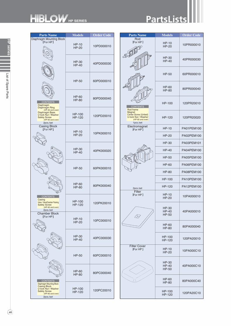
RodFor HP
Parts Name Models Order Code Parts Name Models Order CodeDiaphragm Mounting Block
For HP
CONTENTS
2pcs./set
DiaphragmDiaphragm Ring
(HP-30 and over)Diaphragm BaseU-lock Nut / WasherSafety Screw
(HP-60 and over)
Casing BlockFor HP
HP-10HP-20
HP-30HP-40
HP-50
HP-60HP-80
10PR000010
40PR000030
60PR000010
80PR000040
HP-100 120PR20010
HP-120 120PR20020
HP-10HP-20
HP-30HP-40HP-50
HP-60HP-80
HP-100HP-120
10PA000010
40PA000010
80PA000040
120PA20010
Chamber BlockFor HP
ElectromagnetFor HP HP-10
HP-20
HP-30
HP-40
HP-50
PA01PEM100
PA02PEM100
PA03PEM101
PA04PEM100
PA05PEM100
HP-60 PA06PEM100
HP-80 PA08PEM100
HP-100 PA10PEM100
HP-120 PA12PEM1002pcs./set
FilterFor HP
HP-10HP-20
HP-30HP-40HP-50
HP-60HP-80
HP-100HP-120
10PA000C10
40PA000C10
80PA000C40
120PA20C10
Filter CoverFor HP
HP-10HP-20 10PD000010
HP-30HP-40 40PD000030
HP-50 60PD000010
HP-60HP-80 80PD000040
HP-100HP-120 120PD20010
HP-10HP-20 10PK000010
HP-30HP-40 40PK000020
HP-50 60PK000010
HP-60HP-80 80PK000040
HP-100HP-120 120PK20010
HP-10HP-20 10PC000010
HP-30HP-40 40PC000030
HP-50 60PC000010
HP-60HP-80 80PC000040
HP-100HP-120 120PC20010
CONTENTS
2pcs./set
CasingValve / ValveChamber PackingSafety Screw
(HP-60 and over)
CONTENTS
2pcs./set
Diaphragm Mounting BlockCasing BlockU-lock Nut / WasherSafety Screw
(HP-60 and over)
CONTENTS
1pcs./set
Rod frameMagnetCenter Screw (United)U-lock Nut / Washer
(HP-60 and over)

Parts Name Order CodeModelsValveFor HP
4pcs./set
47
HP
seriesListofS
pareP
arts
HP SERIES PartsListsParts Name Models Order Code
HP-10HP-20
HP-30HP-40HP-50
HP-60HP-80
HP-100HP-120
10PA00PK10
40PA00PK10
FP00200101
FP00200300
Semi Cover PackingFor HP
2pcs./set
HP-10HP-20
HP-30HP-40HP-50
HP-60HP-80
HP-100HP-120
10PN000010
40PN000010
NP03000800
120PN20010
GasketFor HP
HP-10HP-20
HP-30HP-40HP-50HP-60HP-80
HP-100HP-120
PAEC00010P
PAEC00080P
PA12PEM210
Power CordFor HP
HP-10HP-20
HP-60HP-80
HP-50HP-100HP-120
HP-30HP-40
10PF000D10
80PF000D40
120PF20010
Vibration Control RubberFor HP
4pcs./set
HP-50 QN07500100
HP-60HP-80HP-100HP-120
QN08000200
Sound AbsorberFor HP
HP-10HP-20
HP-30HP-40HP-50
HP-60
HP-100HP-120
10PH000U10
40PH000U10
60PH000U40
HP-80 80PH000U40
120PH20010
Upper HousingFor HP
HP-10HP-20
HP-30HP-40HP-50
HP-60HP-80
HP-100HP-120
PALK10
PALKGJL200
PALK0L
PALK1403
L-TubeFor HP
2pcs./set
HP-60HP-80HP-100HP-120
PASPSW0100
Safety ScrewFor HP
All modelsexcept
150GJ-H / 200GJ-HPAJH0L
L-Shaped HoseFor HP
HP-60HP-80
HP-100HP-120
PASPSW
PASPSW01
SP SwitchFor HP
HP-100HP-120
1Set
5Set
10Set
25Set
120VV20010
120VV20020
120VV20030
120VV20040
( )

TROUBLE SHOOTING
Symptom Possible cause Point to check up Remedy
Electrical connection Plug and outlet Plug securely into outlet
Pump fails to work Wire cut inside the cord Check with testerChange power cord, electromagnet or lead wire
SM bar/SP switchactivated
Exchange diaphragmor safety bar/switch
Diaphragm damaged
Faulty valve
Pump works
but makes loud,
irregular noise
Pump works
but no air comes
from reservoir
Faulty
chamber block
Remove upper, lower housing and trace the source of cause
Exchange casing or diaphragm mounting block
Faulty filter Filter clogged Clean up filter
Valve chamber cover out of place Faulty tube Repair or replace
new one
Faulty piping connection
Rubber hose out of palace, broken
Connect properly or replace new one
Pump runs normally Air piping clogged Clean properly
Check• SM Switch Holder• SM Switch Ber• Safety Screw
• Chamber Block
48
Trouble
Shooting

● This pump is designed to pump air. Do not, under any circumstances, attempt to operate in water or other liquids.
● Avoid direct sunlight and install the pump in a well-ventilated place.
● When using the pump to inject air into a liquid, ensure that the pump is higher than the surface level of the liquid, otherwise liquid may run back into the pump when the power is turned off.
● Do not use the pump near volatile liquids such as gasoline, thinner, etc., as this creates the possibility of an explosion.
● Do not block the air being discharged as it may result in malfunction or severely shortened service life.
● Parts require repair or maintenance at least once a year.
● If the pump makes an abnormal noise or the discharged air greatly decreases, immediately turn off the power, because it may be signs of a damaged pump. Please repair the pump.
● Do not touch the pump with bare-hands while pump is operating. The bottom housing temperature may run up to around 158ºF(70ºC)but, this does not affect the operation of the pump.
CAUTION
MEMO
49
Caution

■ Distributor
■ Manufacturer
00M04.3000.M
Headquarters: 8-16, Hatchonishimachi, Takatsuki, Osaka, 569-0095, JAPANTelephone: 0726-84-0805 Fax: 0726-84-0807
Tokyo Office: 8F, Sunwood Machida Bldg., 4-15-13, Haramachida, Machida,Tokyo, 194-0013, JAPANTelephone: 042-720-2882 Fax: 042-720-2883