hfm: hybrid file mapping algorithm for ssd space...
TRANSCRIPT

Appl. Math. Inf. Sci.8, No. 5, 2251-2265 (2014) 2251
Applied Mathematics & Information SciencesAn International Journal
http://dx.doi.org/10.12785/amis/080520
HFM: Hybrid File Mapping Algorithm for SSD SpaceUtilizationJaechun No1,∗, Soo-Mi Choi1, Sung-Soon Park2 and Cheol-Su Lim3
1 College of Electronics and Information Engineering, Sejong University,98 Gunja-dong, Gwangjin-gu, 143-747, Seoul, Korea2 Dept. of Computer Engineering, Anyang University and Gluesys Co. LTD, Anyang 5-dong, Manan-gu, Anyang, 430-714, Korea3 Dept. of Computer Engineering, Seokyeong University, 16-1 Jungneung-dong, Sungbuk-gu, 136-704, Seoul, Korea
Received: 23 Aug. 2013, Revised: 20 Nov. 2013, Accepted: 21 Nov. 2013Published online: 1 Sep. 2014
Abstract: Although the technology of flash memory is rapidly improving, SSD usage isstill limited due to the high cost per storagecapacity. An alternative is to construct the hybrid structure where a smallSSD partition is combined with the large HDD partition, toexpand the file system space to HDD storage capacity while exploiting the performance advantage of SSD. In such a hybrid structure,increasing the space utilization of SSD partition is the critical aspect in generating high I/O performance. In this paper, we present HFM(Hybrid File Mapping) that has been implemented for the hybrid file system integrated with SSD. HFM enables to divide SSD partitioninto several, logical data sections with each composed of the different extent size. To minimize fragmentation overhead, HFM definesthree different ways of partitioning functions based on the extent size ofeach data section. Furthermore, file allocations on the extentare performed on the partitioned unit (segment) of extents to reuse the remaining free space as much as possible. The experimentalresult of HFM using three public benchmarks shows that HFM can be effective in increasing the usage of SSD partition and enables tocontribute to provide better I/O throughput.
Keywords: Hybrid file mapping, partitioning function, map function, map table, allocationunit
1 Introduction
Many file systems have been developed for the purpose ofoptimizing the moving overhead of HDD disk arms in I/Ooperations. However, as the new technologies, such asSSD (Solid State Device), are rapidly improved, the filesystem research for integrating those technologies into thestorage capacity has become received the great attentionbecause they possess the promising performancecharacteristics to satisfy the need of commercialapplications. Especially, SSD that uses flash memory asthe storage medium is considered the next-generationstorage device, due to its advantages such as high randomI/O speed and non-volatility[1].
Although SSD reveals the peculiar devicecharacteristics that do not take place in HDD, such aswear-leveling and block erasure [4,13], several researchesto overcome those obstacles have been performed eitherby implementing FTL (Flash Translation Layer)[14,21],or by implementing flash-specific file systems[9,39].However, the major impediment in utilizing theperformance advantage of SSD for constructing the
large-scale storage space with only SSD still remains,which is the high ratio of cost per capacity as compared tothat of HDD[31,36].
An alternative for solving the problem is to providethe hybrid file system space in which both HDD and SSDpartitions are integrated in a single, virtual file systemaddress space in the cost-effective way. In the hybridstructure, the major consideration is to maximize thespace utilization of SSD partition while efficientlyarranging SSD address space to generate the better I/Obandwidth.
In this paper, we present the hybrid file mappingmethod, called HFM (Hybrid File Mapping), where thefile system space is provided by constructing the hybridstructure with HDD and SSD partitions. To maximize thespace utilization of SSD partition, HFM supports thecapability of dividing the address space of SSD partitioninto multiple, logical data sections with each composed ofthe different I/O unit (extent). The mapping between filesand data sections can be performed by considering the fileaccess characteristics including file size or usage.
∗ Corresponding author e-mail:[email protected]
c© 2014 NSPNatural Sciences Publishing Cor.

2252 J. No et. al. : HFM: Hybrid File Mapping Algorithm for SSD Space Utilization
Furthermore, such a file mapping can be changed withoutaffecting the directory hierarchy.
In order to reduce the fragmentation overhead inproviding the elastic extent size, file allocations in thedata section are performed in the units of segmentsconsisting of extents, which enables to reuse extentscontaining the remaining free space as much as possible.By evaluating HFM with three public benchmarksincluding TPC-C, PostMark, and IOzone, we tried toshow the effectiveness of HFM in generating high I/Operformance. This paper is organized as follows: Insection 2, several researches related to SSD and filesystems are presented. The detailed structure of HFM isdescribed in section3. In section 4, the experimentalresults using the benchmarks are presented. Finally, weconclude in section5.
2 Related Studies
The SSD uses NAND flash memory for the storagemedium. Each flash memory is composed of a set ofblocks that are the erase units[1,2,22,35] and again ablock is consisted of a set of pages that are IO units. Theflash memory only allows erase-write-once behavior.Therefore, to update to the same location, a free block isselected and then the new data is written to the block,along with copying the live data in the original block. Theoriginal block is erased for the block reclamation. Asblocks are involved in the erase operations they becomeworn out and also the lifetime of a flash block for which itguarantees data reliability is limited (100K for SLC and10K for MLC)[27]. As a result, evenly distributing theerase-write cycles among flash blocks is the critical issuein SSDs, which is called wear-leveling[13,37].
The wear-leveling is deeply related to the logical tophysical address mapping since the block worn-outdepends on how often each block is used for writing data.In general, there are two kinds of address mappings toconvert the logical addresses to physical addresses:page-level mapping and block-level mapping. Althoughthe address translation speed of the page-level mapping isfaster than that of block-level mapping, it suffers from thelarge memory requirement to store the map table. On theother hand, the block-level mapping suffers from the slowtranslation speed due to the page-copy operation[29,40].
To overcome the disadvantages of both mappings,several hybrid address translations were proposed. In thelog block-based mapping[21], a few number of log blocksare reserved to collect flash pages. When all the logblocks are exhausted, the pages in the log blocks aremerged with the corresponding data blocks. However, thelog block-based mapping can suffer from the low spaceutilization due to the limited number of log blocks,resulting in the frequent write and erase operations.
The fully-associative section translation[25] tried tosolve the low space utilization by eliminating the conceptof dedicating each log block to a specific data block. The
log block can be used by pages belonging to any datablocks so that the merge with the data block can bedelayed to reduce the write and erase costs. However, ifthe pages in the log block belong to the different datablocks, then the method can cause the significant eraseoperations to merge with the data blocks.
Another way of increasing the space utilization of logblocks is to group data blocks into N data groups and alsoto provide K log blocks at maximum for each data group.The merge operation between pages in the log block andoriginal data blocks takes place in the dedicated datagroup[29]. Chiang et al. also proposed data clusteringalgorithm where data blocks are divided into severalregions based on the write access frequency[5]. When adata block is updated, it moves to the upper region. Onthe other hand, if a segment is selected for cleaning, thenall the valid blocks in the segment are copied into thelower region. Therefore, the separation between hot dataand cold data can be done to reduce the erase operations.
Wu et al. proposed the adaptive flash translation layerwhere the page-level mapping and the block-levelmapping are used according to the recentness[40]. Thepage-level mapping is used for the most recently usedpages. Since the size of the page-level mapping table islimited, some least recently used pages are moved to theblock-level mapping by using LRU list. Also, thedual-pool algorithm proposed by Chang and Du managesdata blocks based on the erase count and prevents the oldblock from being involved in the block reclamation[4].
Also, there were several researches related to thewrite behavior of SSD. For example, Rajimwale et al.found that the write amplification can be reduced bymerging and aligning data to stripe sizes[33]. However,since the related information, such as SSD stripe size, israrely available to file systems, delegating the blockmanagement to SSD and exposing the object-orientedinterface, such as OSD[11,12], to file system might beeffective.
Birrell et al. proposed a way of improving randomwrites on flash disks, by introducing the volatile datastructures[3]. They tested several UFDs (USB FlashDisks) while varying the distance between consequentwrites and found that several UFDs deploy theperformance degradation with far distance between writesdue to read-modify-write to the new flash location. Theyproposed the volatile data structures and algorithms tomitigate such an overhead in random writes.
Besides implementing the sophisticated method inFTL, several researches tried to find a way of reducingwrite and erase costs by rearranging data before passingthem to FTL. Most of such researches were to provideLRU list to keep the frequently referenced pages in thebuffer since those pages will likely to be used soon. Dueto the limited buffer space, the least referenced pages willbe written to flash pages. There are several approaches forselecting pages to evict them from the buffer. CFLRU[30]divides the LRU list into two regions based on a windowsize: working region for including the recently used pages
c© 2014 NSPNatural Sciences Publishing Cor.
Appl. Math. Inf. Sci.8, No. 5, 2251-2265 (2014) /www.naturalspublishing.com/Journals.asp 2253
and clean-first region for including clean pages. Thevictim for the eviction is the page in the clean-first region.The CFLRU/C, CFLRU/E, and DL-CFLRU/E[41] addedmore flexibility in choosing the victim, by referencing theaccess frequency and block erase count. For example, inCFLRU/C, if no clean page is available for the eviction,then the dirty page with the lowest access frequency willbe selected as a candidate. On the other hand, inCFLRU/E, the dirty page with the lowest block erasecount will be chosen for the eviction.
In CFDC[28], the clean-first region of CFLRU isarranged in two queues: one for the clean queue and theother for the priority queue where dirty pages areclustered. The page linked at the tail of the clean queue isfirst selected as a victim. If no clean page is available,then the first page in the lowest-priority cluster is selectedas a victim. LRU-WSR[17] proposed the pagereplacement referencing an additional flag, called coldflag. To delay flushing dirty pages, their cold flag ischecked. If it is marked, then the page is considered as avictim. In case that a dirty page with its cold flag notbeing marked is referenced, the page is moved to MRUposition while marking the cold-flag.
CCF-LRU[26] is another replacement algorithm usingthe cold detection. It differentiates the clean pagesbetween hot and cold by using the cold-flag. It firstsearches the cold clean page for the eviction. If no suchpage is available, then it chooses the cold dirty page as avictim, instead of choosing the hot clean page. InFAB[15], pages in the buffer are clustered based on theerasure block unit. When the buffer is full, FAB chooses ablock containing the largest number of pages as a victim,with the expectation of the switch merge in FTL. In casethat the number of maximum pages of multiple blocks isthe same, a victim is chosen based on LRU order.
BPLRU[20] also selects a block as a victim. It uses thewrite buffer inside SSD and arranges LRU list in units ofblocks. If a logical sector is referenced, then all sectorsbelonging to the same block are moved to the front of thelist. It also chooses the least recent block for the evictionwhile flushing all sectors in the victim together to flashmemory to reduce the log blocks in FTL.
Although the FTL and replacement algorithmsmentioned contribute to reduce the write and erase costsin flash memory, most of them need to have accesses toSSD internals, in order to obtain the block erase count orto use the buffer inside SSD. However, such knowledge oraccesses cannot be available when using the commercialSSD products. In HFM, we tried to exploit a way ofreducing the flash overhead on VFS layer withoutrequiring the knowledge about SSD internals, except forthe flash block size. In our method, given the flash blocksize is known to HFM, the extent size of each data sectioncan be determined to be aligned to flash block boundaries.In case that the extent size is smaller than the flash blocksize, before passing data to SSD partition, the extents arecollected in the in-core map table.
Many researches[6,10,18,23] tried to reduce the costfor write and erase operations by implementing thelog-structured I/O scheme on top of file systems. Thelog-structured file system[34] was proposed to reduce thedata positioning overhead on top of HDD. Instead ofmodifying data in-place, it provides out-of-place updatesby appending the logs at the tail. Since such an I/Opattern well fits to flash memory, many flash file systemshave adopted the log-structured I/O in theirimplementations. JFFS, JFFS2, and YAFFS wereimplemented based on the log-structured mechanism.
JFFS2[39] organizes logs consisted of a linked list ofvariable-length nodes. Each node contains file metadata,such as file name and inode number, and a range of datain the file. When the file system is mounted, the nodes arescanned to construct the directory hierarchy and the mapbetween file positions and physical flash addresses. InYAFFS[10], fixed-sized chunks are organized to containfile metadata and data. The head chunk with chunknumber zero includes file metadata and is used forconstructing the directory hierarchy at file system mount.YAFFS uses the tree-structured map to locate the physicaladdresses associated with file positions.
TFFS[9] was designed for the small embeddedsystems. In TFFS, each erase unit is consisted ofvariable-length sectors and the sectors are divided intotwo parts: one for including descriptors containing theindex to the associated data in the unit and the other forreal data. It also uses the logical pointer to reduce theoverhead of pointer modification due to the unit erasure.One of the interesting flash file systems is FlexFS[24]where the storage space is constructed in the hybridstructure by using MLC and SLC. The new data is firstcollected in the write buffer and flushed into MLC or SLClog blocks. If no space for writing data is available, thenthe data migration takes place to create more free spaces,by moving data from the SLC region to the MLC region.
Conquest[38] also supports the hybrid storage spaceby combining disk to RAM with battery backup. It storessmall files and metadata in RAM and stores large files indisk to favor the performance potential of RAM. ThehFS[42] is another hybrid file system that provides the filesystem space by combining the in-place update pattern ofFFS with the out-of-place update of LFS (Log-structuredfile system). Also, TxFlash[32] provides a new deviceinterface to allow the transactional model. TxFlashexports WriteAtomic(p1, .., pn) that enables to issue asequence of writes in the transaction. The consistency isprovided by implementing the new cyclic commitprotocol.
Finally, DFS[16] provides a support for thevirtualized flash storage layer using fusion-io ioDrive.The virtualized flash storage layer integrates thetraditional block device driver with FTL, to provide a thinsoftware layer while favoring the fast direct speed ofioDrive controller. Also, the layer is responsible for thedirect data path between DFS and the controller, logicalblock to physical page mapping, wear-leveling, and data
c© 2014 NSPNatural Sciences Publishing Cor.

2254 J. No et. al. : HFM: Hybrid File Mapping Algorithm for SSD Space Utilization
distribution between multiple ioDrives. However, sincethe layer is tightly coupled with the ioDrive controller, itmay not be portable to be used other than ioDrive.Furthermore, the cost for providing DFS address space ismuch higher than that of HDD.
The difference between flash file systems and HFM isthat HFM was designed to provide a large-scale storagecapacity by constructing the hybrid file system space.Furthermore, I/Os in HFM take place in-place eventhough it collects data in units of segments within extentsbefore passing them to SSD. Also, HFM does not use asingle I/O unit for the entire SSD storage space. Instead,the different extent size (I/O unit) can be configured foreach logical data section, thus storing files to the differentdata section with the appropriate extent size is possible.
3 System Model
3.1 Overview
The first objective of HFM is to improve the spaceutilization of the restricted SSD storage resources.Second, HFM has been implemented to reduce I/O costby mapping files to the appropriate data section whileconsidering their attributes, such as file size, usage, andaccess pattern. The third objective is to collect as manydata as flash block size on VFS layer prior to passingthem to SSD partition, in order to reduce FTL overhead inwrite and erase operations.
In Fig. 1, the entire file system space of SSD partitionis composed of three logical data sections. On top of thosedata sections, their extent size can elastically be definedbased on the file attributes. The number of data sectionsand the extent and section sizes are defined at file systemcreation. In Fig.1, three data sections,D1, D2, andD3, aredefined with the different extent sizes:x in blocks forD1,y in blocks forD2, andz in blocks forD3 wherex < y < z.
Definition 1. Given a data sectionDn, the associatedHFM is defined asF : attributes → Γn(E,s,ρ). Thepartitioning function Γn of Dn is composed of thefollowings:
– E is the extent ofDn ands is its size in blocks.– ρ ∈ {1,2,3} ∪ φ is the parameter for the segmentpartitioning on extents. Theρ = φ denotes the bypassoperation.
In providing with the logical data sections configuredwith the elastic extent size, the major problem impedingthe space utilization is the extent fragmentation overhead.HFM attempts to solve the fragmentation overhead byclassifying files according to file attributes and bypartitioning the extents to use the remaining space asmuch as possible. There are two kinds of HFM for a file.In the static HFM, the mapping between a file and datasection is defined by the mapping script, which issubmitted at file system mount. For instance, in Fig.1, the
Fig. 1: An overview of HFM
files and subdirectories to be created under/small, /mid,and /large are mapped toD1, D2, andD3, respectively,according to the mapping script. In case that file attributesare changed, for instance creating a directory to storelarge-size files in/small, the data section being mappedto the new directory can be switched to the other datasection consisted of large-size extents, without changingthe directory hierarchy.
In the dynamic HFM, the files are mapped in any datasection based on file size. Letlen[ f ] be the file size inblocks of a file f . In /dynamic, if len[ f ] ≤ x, then f isallocated inD1. If len[ f ] ≥ z,then f is allocated inD3. Inneither of cases,f is allocated inD2. Eventually, in HFM,the I/O cost for accessing large-size files can be reducedby assigning large-size extents to them. Also, the filesdenoting the sequential access pattern, such asmultimedia files, can have I/O benefit by using thelarge-size extents.
On the other hand, the files representing theunpredictable access pattern or size, such as emails, areassigned to small-size extents to minimize the extentfragmentation overhead. Furthermore, the files for backupcan bypass SSD partition, resulting in storing only inHDD partition. As a result, the limited SSD space can beused for only files requiring fast I/O bandwidth.
3.2 Segment Partitioning
In this section, we first describe the partitioning functionapplied to each data section. Since data sections arecomposed of the different extent sizes, HFM provides thedifferent partitioning function for each data section, toreuse the extents possessing the enough free spaces toallocate several files. Also, we describe the map function
c© 2014 NSPNatural Sciences Publishing Cor.

Appl. Math. Inf. Sci.8, No. 5, 2251-2265 (2014) /www.naturalspublishing.com/Journals.asp 2255
Fig. 2: The partitioning function, according to the extentsize andρ
corresponding to each partitioning function, which is usedto determine the block position for the next file allocation.
3.2.1 Partitioning Function
In the partitioning functionΓn(E,s,ρ) with ρ = 1 for adata sectionDn, E is consisted of(log2s)+1 segments. InFig. 1, on top of D1, Γ1(E,x,1) partitions E into{sgi
0|H ≤ i < log2x} whereH = −1. The i denotes thesegment index inE. If i = H, then it is the head segment.Let start[sgi
0] and len[sgi0] be the starting block position
and length in blocks of segmenti. Then,start[sgH0 ] = 0
and len[sgH0 ] = 1. Also, ∀i > H,start[sgi
0] = 2i andlen[sgi
0] = 2i. The partitioning function forD1 is definedas
Γ1(E,x,1) = {(sgH0 ,0)}∪
{(sgi0,2
i)|i ∈ 0,1, · · · ,(log2x)−1}
Example. Fig. 2(a) shows an example of
Γ1(E,x,1) with x = 8 :{(sgH
0 ,0),(sg00,1),(sg1
0,2),(sg20,4)}
In the partitioning functionΓn(E,s,ρ) with ρ = 2, thesegment partitioning is performed in two levels. Aspictured in Fig.1, in the partitioning functionΓ2(E,y,2)of D2, E is partitioned in two levels. In level zero,E isconsisted of log2y segments. To minimize thefragmentation overhead, the largest segment(log2y)− 1is further split into the child segments in level one, Thestarting block position and the length in blocks of the
segments at level zero are the same as inΓn(E,s,ρ) withρ = 1. On the other hand, for the child segments of thelevel one, start[sgH
1 ] = s/2 and len[sgH1 ] = 1. Also,
∀k > H,start[sgk1] = s/2 + 2k and len[sgk
1] = 2k.Therefore,Γ2(E,y,2) is defined as
Γ2(E,y,2) ={(sgH
0 ,0)}∪{(sgi0,2
i)|i ∈ 0,1, · · · ,(log2y)−2}∪{(sgH
1 ,y/2)}∪{(sgk1,y/2+2k)|k ∈ 0,1, · · · ,(log2y)−2}
Example. Fig. 2(b) shows an example of
Γ2(E,y,2) with y = 64 :{(sgH
0 ,0),(sg00,1),(sg1
0,2), · · · ,(sg40,16)}∪
{(sgH1 ,32),(sg0
1,33),(sg11,34), · · · ,(sg4
1,48)}
In the partitioning functionΓn(E,s,ρ) with ρ = 3, thesegment partitioning is recursively performed into thesubsequent level. In Fig.1, with the partitioning functionΓ3(E,z,3) of the data sectionD3, as long as the size ofsegments is no smaller thanδ (segment index islog2δ ),the segments are partitioned into the lower level. Thispartitioning function is used for the large-size extents toconsume the free spaces in extents after file allocations.
In the level zero,E is first partitioned into(log2z) +1 segments whose starting block positions and lengths inblocks are the same as specified inΓn(E,s,ρ) with ρ = 1.The segments whose lengths in blocks are no smaller thanδ are recursively partitioned into the lower level until thelengths of all the child segments become smaller thanδ .
Let sgpL−1 be a segment at levelL − 1 and
len[sgpL−1] ≥ δ . Then, sgp
L−1 is partitioned into
{sg jL|H ≤ j < p}. Also, start[sgH
L ] = start[sgpL−1] and
len[sgHL ] = 1. Furthermore, ∀ j > H, start[sg j
L] =
start[sgpL−1]+2j andlen[sg j
L] = 2j. As a result,Γ3(E,z,3)is defined as
Γ3(E,z,3)= {(sgH
0 ,0)}∪{(sgi0,2
i)|i ∈ 0,1, · · · ,(log2z)−1}= · · ·= {(sgH
L ,start[sgpL−1])}∪
{(sg jL,start[sgH
L ]+2j)| j ∈ 0,1, · · · , p−1},if sgp
L−1 is the parent of those chunks andlen[sgpL−1]≥ δ
= {(sgHL+1,start[sg j
L])}∪
{(sgkL+1,start[sgH
L+1]+2k)|k ∈ 0,1, · · · , j−1},
for ∀sg jL such thatlen[sg j
L]≥ δ
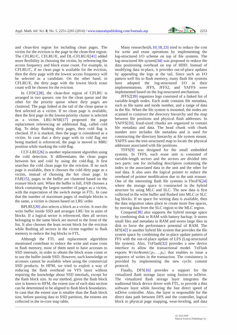
Example. Fig. 2(c) shows an example ofΓ3(E,z,3) withz = 512 andδ = 32 :
{(sgH0 ,0),(sg0
0,1), · · · ,(sg80,256)}
f or sg80−−−−→ {(sgH
1 ,256),(sg01,257), · · · ,(sg6
1,320), · · ·}
c© 2014 NSPNatural Sciences Publishing Cor.
2256 J. No et. al. : HFM: Hybrid File Mapping Algorithm for SSD Space Utilization
f or sg61−−−−→ {(sgH
2 ,320),(sg02,321), · · · ,(sg5
2,352)}f or sg5
2−−−−→ {(sgH3 ,352),(sg0
3,353), · · · ,(sg43,368)}
3.2.2 Map Function
Definition 2. Given a HFMF : attributes → Γn(E,s,ρ) ofthe data sectionDn, let pos be the block position onEwhere the last file has been allocated. If the free space islarger than a threshold value, thenmap(pos,ρ)determines the starting segment from which the next fileis allocated onE.
In Γn(E,s,ρ) with ρ = 1, E is partitioned into(log2s)+1segments. Therefore, if the last segment allocated to a fileis segmenti, then the next allocation starts from segmenti+1.
caseρ = 1 :map(pos,ρ) = (sgi+1
0 ,2i+1) where 2i ≤ pos < 2i+1
In Γn(E,s,ρ) with ρ = 2, E is partitioned into two levels.In case that an allocation ends a segmenti ≤ (log2s)−2,the next allocation starts fromi + 1. Otherwise, the lastsegment(log2s)− 1 is further partitioned into the childsegments in level one and the next allocation processes onthem.
caseρ = 2 :if 2i ≤ pos < 2i+1 andi ≤ (log2s)−2,
map(pos,ρ) = (sgi+10 ,2i+1)
if 2i ≤ pos < 2i+1 andi > (log2s)−2,map(pos,ρ) = map(l pos = pos− s/2,ρ)
= (sgk+11 ,s/2+2k+1)
where⌊2k⌋ ≤ l pos < 2k+1
In Γn(E,s,ρ) with ρ = 3, E is first split into (log2s)+ 1and any segment whose length in blocks is no smallerthanδ (segment index islog2δ ) is further partitioned inthe subsequent level. As a result, on the level zero, if thelast allocation is completed in segmenti < log2δ , then thenext allocation starts from segmenti + 1. Otherwise,segmenti+ 1 is further split prior to the next allocationprocess.
caseρ = 3 : (level 0)if 2i ≤ pos < 2i+1 andi < log2δ ,
map(pos,ρ) = (sgi+10 ,2i+1)
if 2i ≤ pos < 2i+1 andi ≥ log2δ ,map(pos,ρ) = map(l pos = pos− start[sgi
0],ρ)
(level 1)if ⌊2j⌋ ≤ l pos < 2j+1 and j < log2δ ,
map(l pos,ρ) = (sg j+11 ,start[sgi
0]+2j+1)
if ⌊2j⌋ ≤ l pos < 2j+1 and j ≥ log2δ ,map(l pos,ρ) = map(l pos = pos− start[sg j
1],ρ)
. . .(level L)if ⌊2k⌋ ≤ l pos < 2k+1 andk < log2δ ,
map(l pos,ρ) = (sgk+1L ,start[sgH
L ]+2k+1)
if ⌊2k⌋ ≤ l pos < 2k+1 andk ≥ log2δ ,map(l pos,ρ) = map(l pos = pos− start[sgk
L],ρ)
Example.
1. In Γn(E,s,ρ) with s = 8 andρ = 1, let pos = 3. Thenext allocation takes place at segment 2:
map(3,1)21≤3<22
−−−−−→ (sg20,4)
2. In Γn(E,s,ρ) with s = 64 andρ = 2, let pos = 35.The next allocation takes place at segment 2 at levelone:
map(35,2)35−s/2(32)=3−−−−−−−−→
map(3,2)21≤3<22
−−−−−→ (sg21,32+4= 36)
3. In Γn(E,s,ρ) with s = 512 andρ = 3, andδ = 32,let pos = 161. The next allocation takes place atsegment 1 at level two:
map(161,3)27≤161<28,161−start[sg7
0](128)=33−−−−−−−−−−−−−−−−−−−−→
map(33,3)25≤33<26,161−start[sg5
1](128+32=160)=1−−−−−−−−−−−−−−−−−−−−−−−−→
map(1,3)20≤1<21
−−−−−→ (sg12,160+2= 162)
Theorem 1. With extents of size s in blockscomposed of segmentssgi
L where i ∈ {H,0, · · · ,(log2s)−1}, there is at least a sequence of file allocationprocesses by using HFM of the data sectionDn.
Proof. Let ui be the probability that, after executing thefinite partitioning steps,sgi
L no longer participates in thesegment partitioning. Also, letpk(φ) be the probabilitythat k partitioning steps take place atsgi
L and ψi be theprobability distribution of the segments forn incomingfiles. Let τ be the used portion ofsgi
L. In case that theremaining spacelen[sgi
L] − τ becomes smaller thanδafter k partitioning steps, the segment partitioning atsgi
Ldoes not take place. Therefore,ψi is determined as
c© 2014 NSPNatural Sciences Publishing Cor.

Appl. Math. Inf. Sci.8, No. 5, 2251-2265 (2014) /www.naturalspublishing.com/Journals.asp 2257
ψi =
{
ψi−1ui, 0≤ len[sgiL]− τ < δ
p(φ)ψi−1, len[sgiL]− τ ≥ δ (1)
For n files,
ψi = ψi−1ui + p(φ)ψi−1
= ψi−1ui + p(φ)[ψi−2ui + p(φ)ψi−2]
= ψi−1ui + p(φ)ψi−2ui + p2(φ)[ψi−3ui + p(φ)ψi−3]
= ψi−1ui + p(φ)ψi−2ui + p2(φ)ψi−3ui + p3(φ)ψi−3
= ψi−1ui + · · ·+ pk(φ)ψi−(k+1)ui + pk+1(φ)ψi−(k+1)
= ψi−1ui +k
∑r=1
pr(φ)ψi−(r+1)ui + pk+1(φ)ψi−(k+1)
Becauseψi−1ui implies no partitioning steps beingtaken place forn files, it becomes 1. Also, the partitioningsteps cannot exceedk, pk+1(φ)ψi−(k+1) → 0. Therefore,
ψi = 1+k
∑r=1
pr(φ)ψi−(r+1)ui (2)
In (2), on average,
[k
∑r=1
pr(φ)ψi−(r+1)ui]/n = (ψi −1)/n (3)
If n files are all allocated on extents in terms ofsegments, thenψi → n. As a result,
[k
∑r=1
pr(φ)ψi−(r+1)ui]/n = (n−1)/n ≈ 1 (4)
As a consequence, we notice that a file can eventuallybe allocated in extents by using the segment partitiondefined in HFM.
3.3 Extent Reuse
In HFM, the extent reuse is performed by using the in-coremap tableMT (E,s,ρ). TheMT (E,s,ρ) is responsible formanaging the extent free space in memory for reuse priorto the write operation to SSD partition. Also, given theflash block size of SSD partition is known to HFM, if theextent size of a data section is smaller than the flash blocksize, then collecting the extents before write operations isperformed in the map table.
TheMT (E,s,ρ) is constructed per data section and isdifferently organized according to the extent size andρ .With ρ = 1, MT (E,s,ρ) is consisted of a single tablemt0to manage the segments split fromE. On the other hand,with ρ = 2, two tables are included inMT (E,s,ρ): mt0for managing the segments in level zero andmt1 formanaging the child segments in level one. Finally, in
MT (E,s,ρ) with ρ = 3, the segments partitioned at eachlevel are managed by the different table to be organized atthe level.
In MT (E,s,ρ), each table entryenti is connected tothe linked list of extent descriptors whose associatedextents have the largest free space starting from segmenti. The extent descriptor contains the mapping informationabout the associated extent, such as extent address, datasize mapped to the extent, and pointer to the callbackfunction to be invoked when the corresponding extent ismoved to the other table entry. It also contains theinformation about the files mapped to the extent includinginode number.
Fig. 1 shows theMT (E,s,ρ) structure according tothe extent size andρ . Let E0(r),E1(r), · · · ,Ek(r) be thelargest free spaces of extentsE0,E1, · · · ,Ek where thosefree spaces start from segmenti at levelL. Also, for ∀k,let d(Ek) be the extent descriptor ofEk and start[Ek(r)]andlen[Ek(r)] be the starting block position and length inblocks of the largest free space inEk. Suppose that thedescriptors are linked together, in the order ofd(E0),d(E1), · · · , d(Ek).
Definition 3. Given MT (E,s,ρ), a table entryenti ofmtL at levelL is defined as:enti = {d(Ek)|∀k ≥ 0,start[Ek(r)] = start[sgi
L] andlen[E0(r)]≥ len[E1(r)]≥ ·· ·}
In case that the largest free spaces of several extentsstart from the same segment, their descriptors are linkedtogether in the decreasing order of free spaces. InΓn(E,s,ρ) with s = 512 andρ = 3, suppose that a file of162 in blocks was allocated in an empty extent.According to the partitioning rule, the next allocationstarts from(sg1
2,162). The extent descriptor is linked toent1 of mt2 in MT (E,s,ρ). If several extents have thelargest free space starting fromsg1
2, then their extentdescriptors are linked toent1 in the decreasing order offree spaces.
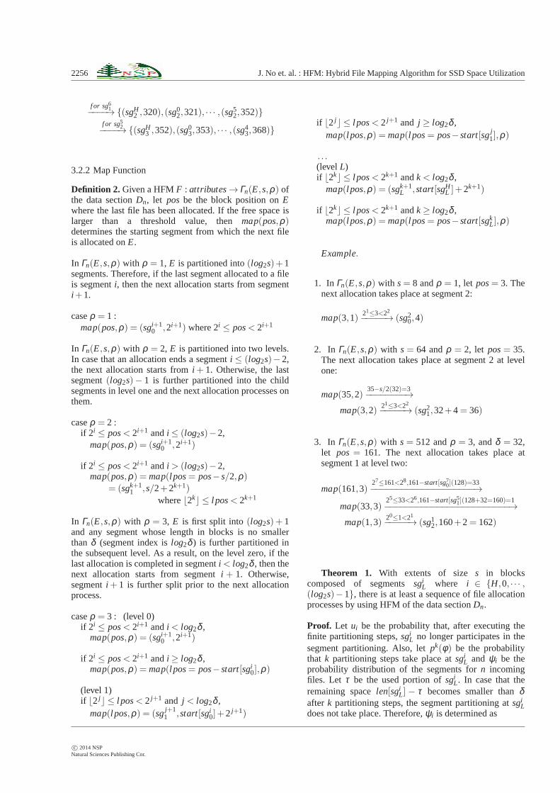
Fig. 3 shows the steps for reusing extents whose freespaces are larger than a thresholdθ . The f is the new fileto be allocated andtime denotes the difference between thetime for which the associated extent has been inserted intothe map table and the time for which the extent is checkedfor the file allocation. In the algorithm, if the flash blocksizebs is known to HFM and the extent sizes is smallerthanbs, then the extent collection takes place in memorybefore writing to SSD partition. Fig.4 describes the stepsto determine the segment index and level where the nextallocation process on the same extent takes place.
HFM maintains the extent bitmap per data section forthe extent availability. At file system mount, HFM checksthe extent bitmap for each data section and pre-allocates1K of empty extents to the map table. In HFM, file writeoperations are simultaneously performed on bothpartitions. When either of partitions completes the writeoperation, control returns user.
The write completion is denoted by a two bits flag,called SSD write done, stored in inode: 00 for
c© 2014 NSPNatural Sciences Publishing Cor.
2258 J. No et. al. : HFM: Hybrid File Mapping Algorithm for SSD Space Utilization
Algorithm 1 Extent ReuseInput: MT (E,s,ρ), f , flash block sizebs if availableOutput: MT (E,s,ρ)
1. HFM periodically organizes 1K of empty extents andtheir descriptors are linked toentH to mt0;
2. if (len[ f ]≥ s)3. use empty extents linked atentH in mt0
for allocating f ;4. letE be the last extent andpos be the last
block position allocated tof on E;5. else6. for all enti ∈ mtL in MT (E,s,ρ)7. select extentE whose largest free space is no
smaller thanlen[ f ] andtime(E) is the longest;8. let pos be the last block position allocated tof ;9. end for
10. end if11. /* id andlevel are the segment index and level for the
next allocation */12. callMap(pos,ρ ,∗id,∗level);13. if (the remaining space drops belowθ )14. if (s < bs)15. collect extents until the total size reachesbs;16. end if;17. else18. move the extent descriptor ofE to entid of mtlevel
in MT (E,s,ρ);19. end if
Fig. 3: Algorithm for the Extent Reuse
initialization, 01 for the completion on HDD partition, 10for the completion on SSD partition, and 11 for thecompletion on both partitions. The flag is also used for thefile read operation. If the flag for SSD partition is markedas one, then the data is read from SSD partition by usingthe extent addresses stored in inode. Otherwise, the readoperation is performed in HDD partition, followed by theduplication to SSD partition as a background.
4 Performance Evaluation
4.1 Experimental Platform
We executed the performance evaluation by using a PCequipped with an AMD Phenom 8650 Triple-core2.3GHz processor, 4GB of RAM, and Seagate Barracuda320GB HDD. The SSD is 80GB of fusion-ioDrive [7].The NAND type of fusion-ioDrive is SLC and thereported bandwidth is 760MB/sec. for reads and540MB/sec. for writes. The access latency is 26s and ituses PCI-E bus interface. In the evaluation, we dividedSSD partition into three logical data sections and mappedto /h f m/small, /h f m/mid, and/h f m/large, which arecomposed of 8KB, 64KB, and 512KB of extent sizes,
Algorithm 2 MapInput: pos, ρOutput: id, level
1. case2. ρ = 1 :3. calculatei such that 2i ≤ pos < 2i+1;4. return (i+1,0)
5. ρ = 2 :6. if (pos ≥ s/2)7. l pos = pos− s/2;8. calculatek such that⌊2k⌋ ≤ l pos < 2k+1;9. return (k+1,1)
10. else11. calculatei such that 2i ≤ pos < 2i+1;12. return (i+1,0)13. end if
14. ρ = 3 :15. level = 0;16. calculatei such that 2i ≤ pos < 2i+1;17. if (len[sgi
0]< δ ) return (i+1,0) end if;18. while (i ≥ log2δ )19. l pos = pos− start[sgi
level ]; level ++;20. calculatei such that⌊2i⌋ ≤ l pos < 2i+1;21. if (len[sgi
level ]< δ ) return (i+1, level) end if;22. end while23. end case
Fig. 4: Algorithm for the map function
Table 1: HFM definition and map table
HFM(1) map directory:/h f m/smallF : attributes → Γn(E,s,ρ)
with s = 8 andρ = 1MT (E,s,ρ) = {mt0}
HFM(2) map directory:/h f m/midF : attributes → Γn(E,s,ρ)
with s = 64 andρ = 2MT (E,s,ρ) = {mt0,mt1}
HFM(3) map directory:/h f m/largeF : attributes → Γn(E,s,ρ)
with s = 512 andρ = 3MT (E,s,ρ) = {mt0,mt1, · · · ,mt4}
respectively. Each data section size is 16GB and HFMblock size is set to 1KB. Theδ for the segmentpartitioning is marked as 32. Therefore, with 512KB ofextent size, the number of partitioning levels is 5(log2s/δ + 1), resulting in constructing five map tables.Table 1 represents the HFM and map table associatedwith each directory hierarchy.
c© 2014 NSPNatural Sciences Publishing Cor.

Appl. Math. Inf. Sci.8, No. 5, 2251-2265 (2014) /www.naturalspublishing.com/Journals.asp 2259
0
1
2
3
4
5
6
7
8
9
10
11
12
50 100 200 300 400 500
xfs(HDD) ext2(HDD) xfs(SSD) ext2(SSD)
HFM(1) HFM(2) HFM(3)
No. of clients
T r a
n s
a c
t i o
n r
a t e
s (
x 1
0 0
0 )
(a) HFM integrated with ext2
0
1
2
3
4
5
6
7
8
9
10
11
12
50 100 200 300 400 500
ext4(HDD) ext4(SSD) HFM(1) HFM(2) HFM(3)
No. of clients
T r a
n s
a c
t i o
n r
a t e
s (
x 1
0 0
0 )
(b) HFM integrated with ext4
Fig. 5: TPC-C Transaction rates (x1000) with 4GB ofRAM
4.2 TPC-C Experiments
TPC-C [8] is the public benchmark for measuring theperformance of online transaction processing systemsusing database. TPC-C typically generates five types oftransactions and constructs nine variously structuredtables in database. The transactions are randomlygenerated by a given number of simultaneously connectedclients. In TPC-C, we used Mysql 5.5 and the databasewas installed on both HDD and SSD partitions. Weexecuted TPC-C on top of HFM(1), HFM(2), andHFM(3) and compared their transaction rates. Also, theperformance result of HFM is compared to that of ext2,ext4 and xfs installed on HDD and SSD. Each file systemuses the database installed on the same partition tominimize the overhead for the database connection.
In Fig. 5(a), the HDD partition of HFM is integratedwith ext2 and its transaction rate(t pmC) is compared to
that of xfs and ext2. Also, in Fig.5(b), the HDD partitionof HFM is integrated with ext4 and its transaction rate iscompared to that of ext4. In both figures, the RAM sizewas configured to 4GB. The number of clientssimultaneously connected to database is varied from 50 to500. As can be seen in the figures, the performanceadvantage of SSD is apparent because the performance ofxfs, ext2 and ext4 installed on SSD shows the large ordersof magnitude I/O improvement, compared to that of thosethree file systems installed on HDD.
Although the database queries of TPC-C producevarious transactions that require to access data from therandom disk position, SSD rarely generates thepositioning overhead for such I/O patterns. In Fig.5(a)and5(b), we can notice that, with 50 client connections,the transaction rate of HFM(3) where the extent size is512KB is 11% and 6% higher, respectively, than that ofHFM(1) where the extent size is 8KB. In the database, theaverage data size for a single write operation is about900KB that is larger than any of extent sizes in HFM.Also, since we do not have the information about the flashblock size, the steps to collect extents whose sizes aresmaller than the flash block size do not take place prior tothe write operation. Consequently, the cost for taking thenecessary extents in HFM(1) is higher than that inHFM(3).
As the number of client connections increases, thetransaction rates become small because of the contentionin I/O devices. Even in this case, the performancesuperiority of SSD is noticeable as compared to that ofHDD.
Fig. 6(a)and6(b) show the transaction rate with 1GBof RAM where the HDD partition of HFM is integratedwith ext2 in Fig.6(a) and with ext4 in Fig.6(b). Due tothe fact that the experiments use the smaller RAM sizethan that in Fig.5(a) and 5(b), the virtual I/O activitytakes place in processing the transactions. For example, inFig. 6(a)and6(b), the transaction rate of HFM(1) with 50clients decreases about 17% and 20%, respectively, ascompared to that with 4GB of RAM in Fig.5(a)and 5(b).However, the benefit using the large-size extent is stillavailable since, with the same number of connections,HFM(3) integrated with ext2 in Fig.6(a) shows 12% ofspeedup, compared to HFM(1). The similar I/O behaviorcan be observed in Fig.6(b) where almost 6% ofperformance improvement can be possible with HFM(3)as compared to HFM(1).
4.3 PostMark Experiments
PostMark has been implemented to measure theperformance of short-lived files, such as electronic mail,netnews, and commerce service [19]. As we did withTPC-C, we executed PostMark on three HFMconfigurations and compared their performance results.The number of files was changed from 1,000 to 20,000and the file sizes were ranged between 500bytes and
c© 2014 NSPNatural Sciences Publishing Cor.

2260 J. No et. al. : HFM: Hybrid File Mapping Algorithm for SSD Space Utilization
0
1
2
3
4
5
6
7
8
9
10
11
12
50 100 200 300 400 500
xfs(HDD) ext2(HDD) xfs(SSD) ext2(SSD)
HFM(1) HFM(2) HFM(3)
No. of clients
T r a
n s
a c t i
o n r
a t e
s (
x 1
0 0
0 )
(a) HFM integrated with ext2
0
1
2
3
4
5
6
7
8
9
10
11
12
50 100 200 300 400 500
ext4(HDD) ext4(SSD) HFM(1) HFM(2) HFM(3)
No. of clients
T r a
n s a
c t i
o n
r a
t e s (
x 1
0 0
0 )
(b) HFM integrated with ext4
Fig. 6: TPC-C Transaction rates (x1000) with 1GB ofRAM
9.77Kbytes. In Fig.7(a), the HDD partition of HFM wasintegrated with ext2 and in Fig.7(b), the HDD partition ofHFM was integrated with ext4. In both figures, we ran100,000 transactions and markedset bias read as 5,therefore append and read operations are equally likely tooccur. As can be seen, with large number of files such asmore than or equal to 10,000 files, the performanceadvantage of SSD is apparent in the file systems due tothe rarely generated the mechanical moving overhead inlocating the desired data.
When we executed PostMark on top of HFM(1), itgenerates the similar bandwidth to ext2 and ext4 installedon SSD. However, on top of HFM(3) with 1000 files, wecan observe about 6% performance speedup on ext2 andext4. As a result, coalescing data into the large I/Ogranularity on VFS layer would be effective on accessingthe continuously being produced small-size files, byreducing the allocation cost. Also, we guess that such an
0
1
2
3
4
5
6
7
8
9
10
11
12
1000 5000 10000 15000 20000
xfs(HDD) ext2(HDD) xfs(SSD) ext2(SSD)
HFM(1) HFM(2) HFM(3)
No. of files
T r a
n s
a c
t i o
n r
a t e
s (
x 1
0 0
0 )
(a) HFM integrated with ext2
0
1
2
3
4
5
6
7
8
9
10
11
12
1000 5000 10000 15000 20000
ext4(HDD) ext4(SSD) HFM(1) HFM(2) HFM(3)
No. of files
T r a
n s
a c t i
o n r
a t e
s (
x 1
0 0
0 )
(b) HFM integrated with ext4
Fig. 7: PostMark Transaction rates (x1000) with 100,000transactions
I/O behavior could reduce the FTL bottleneck in SSDpartition by converting into the large, sequential I/Oaccess pattern.
In PostMark, the small-size files are continuouslygenerated so that there is little delay in the map table tocollect files into the large-size extents. However, if thedelay becomes larger, then collecting files in the maptable can be an obstacle in achieving high I/Operformance. Therefore, choosing the appropriate HFMconfiguration should carefully be performed to achieveI/O improvement. The transaction rates of theexperiments decrease as the number of files becomeslarge because of the reduced number of the availableinodes in the current directory.
Fig. 8(a) and8(b) show the performance results with500,000 transactions. In case of xfs, accessing the largenumber of small-size files does not produce high I/Obandwidth on HDD due to the mechanical moving
c© 2014 NSPNatural Sciences Publishing Cor.

Appl. Math. Inf. Sci.8, No. 5, 2251-2265 (2014) /www.naturalspublishing.com/Journals.asp 2261
0
1
2
3
4
5
6
7
8
9
10
11
12
1000 5000 10000 15000 20000
xfs(HDD) ext2(HDD) xfs(SSD) ext2(SSD)
HFM(1) HFM(2) HFM(3)
No. of files
T r a
n s
a c
t i o
n r
a t e
s (
x 1
0 0
0 )
(a) HFM integrated with ext2
0
1
2
3
4
5
6
7
8
9
10
11
12
1000 5000 10000 15000 20000
ext4(HDD) ext4(SSD) HFM(1) HFM(2) HFM(3)
No. of files
T r a
n s
a c t i
o n r
a t e
s (
x 1
0 0
0 )
(b) HFM integrated with ext4
Fig. 8: PostMark Transaction rates (x1000) with 500,000transactions
overhead. However, in Fig.8(a), we can observe that, with1000 files, such an overhead can be alleviated in SSDbecause of its device characteristics. Also, ext2 and HFMall favor such a promising performance benefit on SSD.On the other hand, in Fig.8(b), with less than 10,000files, there is little advantage in using SSD on top of ext4due to its extent metadata structure. However, convertinginto the large granularity still produces the performanceimprovement, as can be seen in the bandwidthcomparison between ext4 and HFM(3). As the number offiles increases the bandwidth decrement takes place dueto the large number of files being created in the directory.
4.4 IOzone Experiments
In this section, we describe the performance results ofIOzone benchmark. In the first experiment, we modified
0
100
200
300
400
500
600
700
10,000 50,000 100,000 150,000 200,000 250,000 270,000
xfs(HDD) ext2(HDD) ext4(HDD)
xfs(SSD) ext2(SSD) ext4(SSD)
No. of files
I / O
b a
n d
w i d
t h (
M B
/ s e
c . )
(a) ext2, ext4 and xfs
0
100
200
300
400
500
600
700
10,000 50,000 100,000 150,000 200,000 250,000 270,000
HFM(1) HFM(2) HFM(3)
No. of files
I / O
b a
n d
w i d
t h
( M
B / s e
c . )
(b) HFM integrated with ext2
0
100
200
300
400
500
600
700
10,000 50,000 100,000 150,000 200,000 250,000 270,000
HFM(1) HFM(2) HFM(3)
No. of files
I / O
b a
n d
w i d
t h
( M
B / s e
c . )
(c) HFM integrated with ext4
Fig. 9: Type 1 IOzone bandwidth
IOzone in which about 32GB of HDD space and 16GB offusion-io SSD space are filled with two types of files. Inthe first type, 96% (266,240) of small-size files whosesizes are ranged from 8KB to 16KB and 4% (10,200) oflarge-size files whose sizes are from 512KB to 4MB arerandomly generated to occupy both HDD and SSDspaces. In the second type, only the large-size files from512KB to 4MB are written in two devices. We measuredthe bandwidth of the two types with HFM(1), HFM(2),and HFM(3). Also, the I/O throughput of ext2, ext4 andxfs installed on HDD and SSD was compared to that ofHFM.
The first objective of this experiment is to verify thehybrid structure of HFM by observing whether it canpossess the performance advantage of SSD partitionwhile expanding the storage capacity as much as its HDDpartition offers. The second objective is to notice theeffect of its hybrid file mapping based on the file size.
c© 2014 NSPNatural Sciences Publishing Cor.

2262 J. No et. al. : HFM: Hybrid File Mapping Algorithm for SSD Space Utilization
0
100
200
300
400
500
600
700
1,000 3,000 5,000 7,000 9,000 11,000 12,000
xfs(HDD) ext2(HDD) ext4(HDD)
xfs(SSD) ext2(SSD) ext4(SSD)
No. of files
I / O
b a
n d
w i d
t h (
M B
/ s e
c . )
(a) ext2, ext4 and xfs
0
100
200
300
400
500
600
700
1,000 3,000 5,000 7,000 9,000 11,000 12,000
HFM(1) HFM(2) HFM(3)
No. of files
I / O
b a
n d
w i d
t h
( M
B / s e
c . )
(b) HFM integrated with ext2
0
100
200
300
400
500
600
700
1,000 3,000 5,000 7,000 9,000 11,000 12,000
HFM(1) HFM(2) HFM(3)
No. of files
I / O
b a
n d
w i d
t h
( M
B / s e
c . )
(c) HFM integrated with ext4
Fig. 10: Type 2 IOzone bandwidth
Fig. 9(a) shows the write throughput of type 1 forext2, ext4 and xfs installed of HDD and SSD. Also, bothFig. 9(b)and Fig.9(c) show the result of the same type onHFM integrated with ext2 and ext4, respectively.Although ext2, ext4 and xfs installed on SSD enable toproduce high I/O performance, their storage capacity isquickly exhausted as compared to that of the same filesystems built on HDD. However, in HFM, since its filesystem space is integrated with HDD, it can write untilthe entire HDD partition is occupied with files.
In type 1, the majority is the small-size files andtherefore the delay in the map table takes place with thelarge-size extents, which degrades I/O bandwidth withHFM(3). In Fig.9(b)and Figure9(c), we can observe thatabout 12% and 14% of performance difference occursbetween HFM(1) and HFM(3) with 10,000 files,respectively. Also, we can notice that the periodicperformance turbulence takes place in HFM due to theextent replacement. We believe that, with the larger SSD
capacity, the period between consecutive replacementsbecomes longer so that the turbulence would bealleviated.
Fig. 10(a)illustrates the write throughput of type 2 forext2, ext4 and xfs installed on HDD and SSD. In Type 2,the file sizes being written are between 512KB and 4MB.With such file sizes, the storage capacity of SSD isexhausted when the number of files exceeds about 7,500.However, as can be seen in Fig.10(b) and10(c), the filesystem space of HFM is restricted by HDD capacityrather than SSD due to its hybrid structure. In Fig.10(b),with the large-size files, the performance advantage ofHFM(3) is apparent as compared to that of ext2 installedon SSD and that of HFM(1). This is because HFM(3)requires to allocate the less number of I/O units than ext2and HFM(1) do. For example, with 1,000 files, HFM(3)shows 23% and 16% of performance improvement,compared to ext2 on SSD and HFM(1). We can observethe similar I/O behavior in Fig.10(c) where about 14%and 9% of bandwidth speedup can be observed withHFM(3) as compared to that of ext4 on SSD and HFM(1).
In the second experiment pictured in Fig.11(a)and 11(b) where the HDD partition of HFM wasintegrated with ext2 in Fig.11(a) and was with ext4 inFig. 11(b). We varied file sizes and mapped those files toeach extent size of HFM, in order to observe what kind ofmapping is effective for each file size. In both figures,with 8KB of file size, using HFM(3) composed of 512KBof extent size produces rather less I/O throughput thanusing HFM(1) composed of 8KB of extent size. This isbecause 8KB of file sizes should wait at the map tableuntil the whole extent size is used for storing several files.However, with 256MB of files, using HFM(3) shows 6%of improvement in Fig.11(a)and 3% of improvement inFig. 11(b)as compared to using HFM(1). This is becauseit does not cause any delay at the map table and alsoneeds the less number of extents than using 8KB ofextents.
It is noted that the mapping between files and SSDdata section should carefully be performed to producebetter I/O performance. One efficient way is to use thelarge-size extent for storing the large-size files. Also,using the large-size extent can be effective even with thesmall-sized streaming files. However, for theunpredictable-sized files, using the large-size extent maynot be efficient due to the delay to fill out the wholeextent. In this case, those files should be mapped to SSDdata section configured with the small-size ormedium-size extent.
5 Conclusion
Due to its promising advantages, integrating SSD into thestorage capacity is becoming the main issue in the filesystem development. Although its peculiar devicecharacteristics, such as erase-write-once andwear-leveling, can be overcome either by implementing
c© 2014 NSPNatural Sciences Publishing Cor.

Appl. Math. Inf. Sci.8, No. 5, 2251-2265 (2014) /www.naturalspublishing.com/Journals.asp 2263
0
200
400
600
800
1000
8KB 64KB 512KB 1MB 4MB 16MB 64MB 256MB
xfs(HDD) ext2(HDD) xfs(SSD) ext2(SSD)
HFM(1) HFM(2) HFM(3)
File size
I / O
b a
n d
w i d
t h (
M B
/ s e
c . )
(a) HFM integrated with ext2
0
200
400
600
800
1000
8KB 64KB 512KB 1MB 4MB 16MB 64MB 256MB
ext4(HDD) ext4(SSD) HFM(1) HFM(2) HFM(3)
File size
I / O
b a
n d
w i d
t h (
M B
/ s e
c . )
(b) HFM integrated with ext4
Fig. 11: IOzone bandwidth compared to ext2, ext4 and xfsinstalled on HDD and SSD
an efficient FTL algorithm, or by implementingflash-specific file systems, the high ratio of cost percapacity as compared to HDD remains an obstacle inbuilding the large-scale storage subsystems with onlySSDs. An alternative is to construct the hybrid structurewhere a small SSD partition is combined with the largeHDD partition, to provide a single virtual address spacewhile favoring the performance advantage of SSD. Insuch a hybrid structure, maximizing the space usage ofSSD partition is the critical issue in generating high I/Operformance. HFM was developed to improve the spaceutilization of the restricted SSD storage resources. InHFM, SSD partition can be organized into several, logicaldata sections with each composed of the different extentsize. In order to reduce the fragmentation overhead, HFMdefines three ways of partitioning functions based on theextent size. In the small-size extent(ρ = 1), the extent ofsize s is composed of(log2s) + 1 segments and the file
allocation steps are performed in units of segments in theextent. In the medium-size extent(ρ = 2), the lastsegment is more split into level one to reuse theremaining free space of the extent and then in thelarge-size extent(ρ = 3), the segments whose segmentsize is larger than or equal to the threshold(δ ) arerecursively partitioned until the sizes of all segmentsbecome smaller than the threshold. We executed theperformance evaluation of HFM by using three publicbenchmarks, including TPC-C, PostMark, and IOzone. Inthe evaluation, SSD partition is divided into three logicaldata sections and each data section is configured with8KB, 64KB, and 512KB of extents, followed by mappingthem to the different directory hierarchies. In TPC-C, theperformance advantage of SSD is apparent because theperformance of HFM and ext2 and ext4 installed on SSDshows the large orders of magnitude I/O improvement,compared to those file systems installed on HDD. Also,since I/O size in TPC-C is larger than any of extent sizes,using the large I/O granularity produces better I/Obandwidth than using the small-size extent. Such an I/Obehavior is also available even though the transactionrates become small due to the increased number ofsimultaneous client connections. In PostMark experiment,we can notice that, in most cases, SSD works better thanHDD in accessing small-size files because of the absenceof the mechanical moving overhead in SSD. Also, evenwith small-size files, using the large-size extentcontributes to generate the performance speedup becausethe delay in the map table is reduced due to thecontiguously being generated files. In IOzone benchmark,we can observe that HFM enables to expand its storagecapacity to its HDD partition due to the hybrid structure.However, there is a delay in writing small-size files withthe large-size extent, therefore the mapping between filesand SSD data section should carefully be performed. Oneefficient way is to use the large-size extent for storing thelarge-size files or the small-sized streaming files.However, for the unpredictable-sized files, using thelarge-size extent may not be efficient due to the delay tofill out the whole extent. In this case, those files should bemapped to SSD data section configured with thesmall-size or medium-size extent. As a future work, wewill experiment HFM with real applications where a largenumber of various-sized files are generated, to verify itseffectiveness in generating better I/O performance.
Acknowledgement
This work was supported by the Industrial ConvergenceStrategic Technology Development Program, Grants No.10045299 and 10047118, funded by the Ministry ofScience, ICT and Future Planning, Korea 2013. Also, thiswork was partially supported by BRL program throughthe NRF of Korea (2010-0019373).
c© 2014 NSPNatural Sciences Publishing Cor.
2264 J. No et. al. : HFM: Hybrid File Mapping Algorithm for SSD Space Utilization
References
[1] N. Agrawal, V. Prabhakaran, T. Wobber, J.D. Davis, M.Manasse and R. Panigrahy, Design Tradeoffs for SSDPerformance, Proc. USENIX Annual Technical Conference,San Diego, CA, 57-90 (2008).
[2] R. Bez, E. Camerlenghi, A. Modelli and A. Visconti,Introduction to Flash Memory, In Proceedings of the IEEE,91, 489-502 (2003).
[3] A. Birrell, M. Isard, C. Thacker and T. Wobber, A Design forHigh-Performance Flash Disks, ACM SIGOPS OperationSystems Review,41, 88-93 (2007).
[4] L.P. Chang and C.D. Du, Design and Implementation ofan Efficient Wear-Leveling Algorithm for Solid-State-DiskMicrocontrollers, ACM Transactions on Design Automationof Electronic Systems,15, 1-36 (2009).
[5] M.L. Chiang, P. Lee and R.C. Chang, Using Data Clusteringto Improve Cleaning Performance for Flash Memory,Software-Practice and Experience,29, 267-290 (1999).
[6] H. Dai, M. Neufeld and R. Han, ELF: An Efficient Log-Structured Flash File System For Micro Sensor Nodes, Proc.SenSys’04, Baltimore, USA, (2004).
[7] Fusion-io, ioDrive User Guide for Linux, (2009).[8] Fujitsu Technology Solutions, Benchmark Overview TPC-
C, White paper, (2003).[9] E. Gal and S. Toledo, A Transactional Flash File System
for Microcontrollers, Proc. USENIX Annual TechnicalConference, Anaheim, CA, 89-104 (2005).
[10] E. Gal and S. Toledo, Algorithms and data structures forflash memories, ACM Computing Surveys (CSUR),37, 1-30 (2005).
[11] G.A. Gibson, D.F. Nagle, K. Amiri, J. Butler, F.W. Chang,H. Gobioff, C. Hardin, E. Riedel, D. Rochberg and J.Zelenka, A Cost-Effective, High-Bandwidth StorageArchitecture, Proc. 8th International Conference onArchitectural Support for Programming Languages andOperating Systems, 92-103 (1998).
[12] J. Griffin, S. Schlosser, G. Ganger and D. Nagle, OperatingSystem Management of MEMS-based Storage Devices,Proc. 4th Symposium on Operating Systems Design andImplementation, San Diego, CA, (2000).
[13] J.W. Hsieh, T.W. Kuo and L.P. Chang, EfficientIdentification of Hot Data for Flash-Memory StorageSystems, ACM Transactions on Storage,2, 22-40 (2006).
[14] Intel Corporation, Understanding the flash translationlayer(FTL) specification, Technical Report, (1998).
[15] H. Jo, J. Kang, S. Park, J. Kim and J. Lee, FAB: Flash-AwareBuffer Management Policy for Portable Media Players,IEEE Transactions on Consumer Electronics,52, 485-493(2006).
[16] W. Josephson, L. Bongo, K. Li and D. Flynn, DFS: A FileSystem for Virtualized Flash Storage, Proc. 8th USENIXconference on file and storage technologies (FAST’10), SanJose, CA, (2010).
[17] H. Jung, H. Shim, S. Park, S. Kang and J, Cha, LRU-WSR: Integration of LRU and Writes Sequence Reorderingfor Flash Memory. IEEE Transactions on ConsumerElectronics,54, 1215-1223 (2008).
[18] J. Jung, Y. Won, E. Kim, H. Shin and B. Jeon, FRASH:Exploiting Storage Class Memory in Hybrid File System forHierarchical Storage, ACM Transactions on Storage,6, 1-25(2010).
[19] J. Katcher, PostMark: A New File System Benchmark,Technical report, Network Appliance, Inc., (1997).
[20] H. Kim and S. Ahn, BPLRU: A Buffer Management Schemefor Improving Random Writes in Flash Storage, Proc. 6thUSENIX Symposium on File and Storage Technologies,San Jose, CA, 239-252 (2008).
[21] J. Kim, J.M. Kim, S. Noh, S. Min and Y. Cho, ASpace-Efficient Flash Translation Layer for CompactFlashSystems, IEEE Transactions on Consumer Electronics,48,366-375 (2002).
[22] J. Kim, H. Lee, S. Choi and K. Bahng, A PRAM and NANDFlash Hybrid Architecture for High-Performance EmbeddedStorage Subsystems, Proc. EMSOFT’08, Atlanta, GA,(2008).
[23] C. Lee, S. Baek and K. Park, A Hybrid Flash File SystemBased on NOR and NAND Flash Memories for EmbeddedDevices, IEEE Transactions on Computers,57, 1002-1008(2008).
[24] S. Lee, K. Ha, K. Zhang, J. Kim and J. Kim, FlexFS: AFlexible Flash File System for MLC NAND Flash Memory,Proc. USENIX Annual Technical Conference, San Diego,USA, (2009).
[25] S. Lee, D. Park, T. Chung, D. Lee, S. Park and H.Song,A Log Buffer-Based Flash Translation Layer Using Fully-Associative Sector Translation, ACM Transactions onEmbedded Computing Systems,6, 1-27 (2007).
[26] Z. Li, P. Jin, X. Su, K. Cui and L. Yue, CCF-LRU: ANew Buffer Replacement Algorithm for Flash Memory,IEEE Transactions on Consumer Electronics,55, 1351-1359(2009).
[27] A. Olson and D. Langlois, Solid State Drives-DataReliability and Lifetime. White paper, Imation Inc., (2008).
[28] Y. Ou, T. Harder and P. Jin, CFDC: A Flash-awareReplacement Policy for Database Buffer Management. Proc.fifth International Workshop on Data Management on NewHardware, Province, RI, 15-20 (2009).
[29] C. Park, W. Cheon, J. Kang, K. Roh, W. Cho and J. Kim, AReconfigurable FTL(Flash Translation Layer) Architecturefor NAND Flash based Applications, ACM Transactions onEmbedded Computing Systems,7, 1-23 (2008).
[30] S. Park, D. Jung, J. Kang, J. Kim and J. Lee, CFLRU:A Replacement Algorithm for Flash Memory, 2006international conference on compilers, architecture andsynthesis for embedded systems, Seoul, Korea, (2006).
[31] M. Polte, J. Simsa and G. Gibson, Comparing Performanceof Solid State Devices and Mechanical Disks, Proc. 3rdPetascale Data Storage Workshop held in conjunction withSupercomputing’08, Auxtin, TX, (2008).
[32] V. Prabhakaran, T. Rodeheffer and L. Zhou, TransactionalFlash, Proc. 8th USENIX Symposium on Operating SystemsDesign and Implementation, San Diego, CA, 147-160(2008).
[33] A. Rajimwale, V. Prabhakaran and J. Davis, BlockManagement in Solid-State Devices, Proc. USENIX AnnualTechnical Conference, San Diego, CA, (2009).
[34] M. Rosenblum and J. Ousterhout, The Design andImplementation of a Log-Structured File System, ACMTransactions on Computer Systems,10, (1992).
[35] Samsung Electronics, K9XXG08XXM Flash Memory.Technical paper, Samsung Inc., (2007).
c© 2014 NSPNatural Sciences Publishing Cor.

Appl. Math. Inf. Sci.8, No. 5, 2251-2265 (2014) /www.naturalspublishing.com/Journals.asp 2265
[36] M. Saxena and M. Swift, FlashVM: Virtual MemoryManagement on Flash, Proc. USENIX Annual TechnicalConference. Boston, Massachusetts, (2010).
[37] G. Soundararajan, V. Prabhakaran, M. Balakrishnan and T.Wobber, Extending SSD Lifetimes with Disk Based WriteCaches, Proc. 8th USENIX Conference on File and StorageTechnologies (FAST’10), San Jose, CA, (2010).
[38] A. Wang, G. Kuenning, P. Reiher and G. Popek, TheConquest File System: Better Performance Through aDisk/Persistent-RAM Hybrid Design, ACM Transactions onStorage,2, 1-33 (2006).
[39] D. Woodhouse, JFFS: The Journaling Flash File System.Proc. Ottawa Linux Symposium, Ottawa, (2001).
[40] C. Wu, H. Lin and T. Kuo, An Adaptive Flash TranslationLayer for High-Performance Storage Systems, IEEETransactions on Computer-Aided Design of IntegratedCircuits and Systems,29, 953-965 (2010).
[41] Y. Yoo, H. Lee, Y. Ryu and H. Bahn, Page ReplacementAlgorithms for NAND Flash Memory Storages, Proc. ofICCSA, Kuala Lumpur, Malaysia, 201-212 (2007).
[42] Z. Zhang and K. Ghose, hFS: A Hybrid File SystemPrototype for Improving Small File and MetadataPerformance, Proc. EuroSys’07, Lisboa, Portugal, (2007).
Jaechun No receivedthe Ph.D. degree in ComputerScience from SyracuseUniversity in 1999. Sheworked as a postdoctoralresearcher at ArgonneNational Laboratoryfrom 1999 to 2001. She alsoworked at Hewlett-Packardfrom 2001 to 2003. She is
professor of the College of Electronics and InformationEngineering at Sejong University. Her research areasinclude file systems, large-scale storage system and cloudcomputing.
Soo-Mi Choi
is currently an AssociateProfessor in the Departmentof Computer Engineering atSejong University, Seoul, Korea.She received her B.S., M.S.and Ph.D. degrees in ComputerScience and Engineeringfrom Ewha University ofKorea in 1993, 1995 and 2001,
respectively. After she received her Ph.D., she joined the Centerfor Computer Graphics and Virtual Reality (CCGVR) at EwhaUniversity as a Research Professor. In 2002, she became afaculty member in the Department of Computer Engineering atSejong University. From September 2008 to August 2009 shewas a Visiting Scholar at the CG Lab of ETH Zurich inSwitzerland. Her current research interests include computergraphics, virtual reality, human-computer interaction, andubiquitous computing.
Sung-Soon Parkreceived the Ph.D. degreein Computer Science fromKorea University in 1994. Heworked as a Fulltime Lecturerat Korea Air Force Academyfrom 1988 to 1990. Healso worked as a postdoctoralresearcher at NorthwesternUniversity from 1997 to
1998. He is professor of the Department of ComputerScience and Engineering at Anyang University and alsoCEO of Gluesys Co. LTD. His research areas includenetwork storage system and cloud computing.
Cheol-Su Lim
received the Master’sdegree from IndianaUniv. and Ph.D. degree inComputer Engineering fromSogang Univ. respectively. Heworked as a senior researcherat SK Telecomm from 1994to 1997. He also worked asNational Research Program
Director from 2009 to 2010. He is professor of the Dept.Computer Engineering at Seokyeong University. Hisresearch areas include multimedia system and cloudcomputing.
c© 2014 NSPNatural Sciences Publishing Cor.