heritage management challenges and resolutions: … management challenges and resolutions:...
TRANSCRIPT
Heritage Management Challenges and Resolutions:Monitoring Submerge
Heritage Management Challenges and Resolutions:Submerged World War II M4 Sherman Tanks
in Saipan, CNMI
Matthew Hanks
Master of Maritime Archaeology Department of Archaeology
Flinders University South Australia
2010
Heritage Management Challenges and Resolutions: d World War II M4 Sherman Tanks

Hanks
i
DECLARATION
This thesis represents original research undertaken for the Masters in Maritime
Archaeology Degree at Flinders University. It was completed in 2010. The
interpretations presented in this thesis are my own and do not represent the view of any
other individual or group.
Matthew L. Hanks
December 2010
**Cover Photo Credit: James Hunter III, July 2009.

Hanks
ii
ABSTRACT
During June and July 1944, a brutal battle raged on the island of Saipan. The
United States’ victory over Japan placed B-29 bombers within range of Japan and a
proved to be a crucial turning point of World War II in the Pacific. As a result of this
battle, military equipment is strewn over and around the island to this day, serving as a
solemn reminder of the Battle of Saipan. Three easily accessible, partially submerged
M4 Sherman tanks have been a popular destination for beach visitors and local fishers
for over 60 years. This activity has likely had a negative impact on the stability of the
sites. This thesis presents the first academic study to consider the assessment,
monitoring, and management of these World War II-era tanks on Saipan,
Commonwealth of the Northern Marianas Islands (CNMI). This research included the
archaeological surveying and mapping of the Sherman tanks, including the
identification and assessment of natural and cultural impacts that have affected and are
affecting the tanks. This data was collected in order to develop a framework for
conducting future monitoring of the sites. This work will facilitate the evolution of a
regular monitoring program for the sites in conjunction with local heritage officers at
the CNMI Historic Preservation Office to preserve the tanks for the enjoyment of future
generations.

Hanks
iii
ACKNOWLEDGEMENTS
Firstly, I would like to thank the faculty of the Flinders University Department
of Archaeology, particularly Dr. Jennifer McKinnon. There are many who have
provided me with guidance and support, but Jen’s unceasing patience and invaluable
feedback is unparalleled. John Naumann, Maritime Archaeology Technical Officer, for
maintaining, organizing, and providing the copious amounts of equipment necessary for
the project as well as lending a hand in recording data. Cheers to Jason Raupp for his
encouragement and sharing his knowledge, experience, and insight.
I would also like to acknowledge the staff of the Division of Historic
Preservation for their assistance on site in Saipan and provision of research materials.
Staff archaeologists Ronnie H. Rogers, Herman Tudela, and John D. Palacios were
instrumental in the completion of this work, providing keen input and advice.
Dr. Toni Carrell of Ships of Discovery provided priceless historical/background
research. David Ulloa and Dee McHenry, project photographers and videographers,
provided beautiful images of the sites.
A massive thanks to my fellow Master of Maritime Archaeology students at
Flinders University as well as my peers from Florida State University, Texas A&M
University, and University of Technology, Sydney. Without their eagerness and work
ethic, recording the tanks would have been a daunting task. Sam Bell, Ash Fowler, and
Rachel Katz, in particular, for their continued support after the fieldwork.
I have received unabated support and encouragement from those back home. It
has been a long road. My parents, brother, and friends have all nudged me along. Thank
you.
A portion of the research was supported through an American Battlefield
Protection Program (ABPP) grant. This material is based upon work assisted by a grant
from the Department of the Interior, National Park Service. Any opinions, findings, and
conclusions or recommendations expressed in this material are those of the author(s)
and do not necessarily reflect the views of the Department of the Interior.

Hanks
iv
TABLE OF CONTENTS
Declaration……………………………………………….……………………………... i Abstract………………………………………………………………………………… ii Acknowledgements………………………………………...…………………………...iii Table of Contents……………………………………………………………………… iv List of Figures………………………………………………………………………..... vi List of Tables…..………………………………………………….……………...……. xi Chapter One: Introduction……………………………………….…………………... 1 Introduction……...………………………………….…………………………... 1 Aims and Objectives…………………………….……………………………… 3 Significance…………………………………………………………….............. 6
Thesis Outline……………………………….…………………………….......... 6 Chapter Two: Historical Background……………….………………….…………… 8 Location of Saipan…………………………….………………………………... 8 Saipan 1918-1944……………………………………….…………………….... 8 Battle of Saipan…………………………………………...………………........ 12
The M4 Sherman Tank……………………………......………….…………… 18 Sherman Tanks in Saipan……......……………………………………………. 22 Chapter Three: Literature Review………………………...……………………….. 24 World War II Tank Archaeology……………………...………………………. 24 Applicable Legislation…………………………………...……………………. 30 CNMI Historic Preservation Plan…………………………...………………… 33 Heritage Tourism in the Mariana Islands……………………..………………. 35 Chapter Four: Methodology…………………………………………...……………. 37 Research Methods………………………………………………...…………… 37 Archival Research…………………………………………...………… 37 Personal Communication with HPO Heritage Officers……...……….. 38 Previous Work on M4 Sherman Tanks………...……………………...………. 38 Previous Assessment Work in Micronesia……………...…………………….. 40
Data Collection……………………………………………………...…...……. 41 Equipment……………………………………………………………... 41
Shoreline Survey…………………………………………………...….. 41 On-site Survey…………………….………………………………...…. 42 Visitors and Rubbish…………………………………………...……… 42 Corrosion/Deterioration………………………………………………. 43 Depth Measurements……………………………………………...…... 44

Hanks
v
Vegetation……………………………………………………...……… 44 Limitations in the Methodology……...…………………………………...…... 45 Chapter Five: Data Analysis………………………………………………...………. 46 Saipan’s Shermans: Site Locations and Description…………………..…….... 46 General Location………………………………………………..…….. 46 Flora and Fauna………..………………………………………..……. 49 Environmental Conditions………………………………………..…… 49 Corrosion…………………………………………………………..….. 49
Tank 1…………………………………………………………………………. 50 Description………………………………………………………..…... 50
Data Collected……………………………………………………….... 52 Tank 2…………………………………………………………………………. 61
Description………………………………………………………..…... 61 Data Collected……………………………………………………….... 63
Tank 3…………………………………………………………………………. 69 Description………………………………………………………..…... 69
Data Collected……………………………………………………….... 71 Tides………………………………………………………………..…………. 77 High Nickel Content Welds…………………………………………...………. 78 Tank Comparison…………………………………………………...…………. 79
Historic Preservation Policies and Practice……………………...……...…….. 80 Management Challenges…………………………………………………...….. 80 Future Objectives…………………………………………………………….... 82 Chapter Six: Discussion and Conclusions…………………………..……………… 85
What Issues and Challenges are Involved in the Heritage Management of Submerged Sites in the CNMI Where Public Visitation is Encouraged and How Can These be Addressed in the Development of a Regular Monitoring Program?……………………………………………………......………..……. 85
Proposed Monitoring Plan…………………………….…………..…………... 88 Natural and Cultural Impacts in Detail……………………………….. 91 Implementation of Proposed Monitoring Plan…..…………….....………….. 102 Dissociation Theories…………………………………..…………..………... 103 Further Research………………………………………………….....……….. 107 Conclusion…………………………………………………………………… 108 Appendix I: E-mail Correspondence Between Author and Ronnie Rogers, HPO,
CNMI………………………………………………..…………..….…. 110 Appendix II: Biological Survey Data Tables……...…………..……………..……. 111 References……………………………………………………………………..…..… 113

Hanks
vi
LIST OF FIGURES
Figure 1-1. Location of the Commonwealth of the Northern Mariana Islands (CNMI) and Saipan. (Intute Webpage, accessed 26 Sept 2010)…….………………..…. 2
Figure 1-2. The topography, Japanese defenses, and U.S. invasion scheme of Saipan.
(Blodgett n.d., accessed 30 Nov 2010)………………………..………………... 4 Figure 2-1. Map depicting the movement of Allied forces and extent of Japanese
occupation in the Far East and the Pacific from 1941-1945. (The Map Database 2009, accessed 5 Sept 2010)………………………………………………..…. 11
Figure 2-2. Image of a Boeing B-29 Superfortress over Korea. (B-29s Over Korea
Webpage 2010, accessed 6 Sept 2010)……………………………………...… 12 Figure 2-3. American soldier sitting on an unexploded sixteen-inch shell.
(Chapin 1994: 27)…………………………………………………….……….. 14 Figure 2-4. Saipan invasion beaches June 14-15, 1944. Map design by James W. Hunter
III, Ships of Discovery. (Carrell 2009: 298)…………………………..………. 15
Figure 2-5. Sketch of a base version of a M4 Sherman tank depicting key components.
(University of San Diego Webpage 2010, accessed 29 Aug 2010)…..……….. 18 Figure 3-1. American M4A1 Sherman tank being inspected by a member of the
Philippine Coast Guard after removal from Manila Bay. (Army Times Webpage 2009, accessed 23 Aug 2010)…..……………………………….………….…. 25
Figure 3-2. Japanese Type 97 Chi Ha light tank resting at a depth of 120 feet on the
deck of the Nippo Maru. (Dive Gallery Webpage 2010, accessed 23 Aug 2010)……………………………….………………………………………..… 25
Figure 3-3. Soviet KV-1 heavy tank being extracted from the Neva River outside St.
Petersburg in 2003. (Around St. Petersburg Webpage 2010, accessed 23 Aug 2010)………………………………………………………...……………...…..26
Figure 3-4. DD Sherman tank afloat with canvas screen up during testing and onshore
with screen down during testing. (Lone Sentry Webpage 2010, accessed 23 Aug 2010)………………………………………………………………...……..….. 28
Figure 3-5. Allied troops wade ashore on Omaha beach on D-Day, 6 June 1944. (Keep
Your Helmet On Webpage 2009, accessed 24 Aug 2010)………………...….. 29 Figure 4-1. Team members pulling the tape taut to measure the distance to peripheral
vegetation. (Flinders University, photo by A. Legra, 2010)………………..…. 44

Hanks
vii
Figure 5-1. Map illustrating the location of the three M4 Sherman tanks off the western
coast of Saipan, CNMI. (Florida State University, Rachel Katz, 2010)……..... 47 Figure 5-2. Map showing the approximate distances (in meters) from shore to the three
M4 Sherman tanks. (Florida State University, Rachel Katz, 2010)…………... 48 Figure 5-3. The turret and main gun of Tank 1 protruding from the water. (Flinders
University, photo by T. Massey, 2010)……………………………………….. 51 Figure 5-4. The bow and forward hull of Tank 1. (Flinders University, photo by T.
Massey, 2010)…………………………………………………………………. 51 Figure 5-5. Serial number D50878 on the turret of Tank 1. (Flinders University, photo
by T. Massey, 2010)………………………………………………………..…. 52 Figure 5-6. Plan view and starboard profile view of Tank 1. (Flinders University,
site plan by M. Hanks, 2010)………………………...………………………... 53 Figure 5-7. Photo of the buried track and roller assembly of Tank 1. 50 centimeter
scale. (Flinders University, photo by T. Massey, 2010)………...…………….. 54 Figure 5-8. Accumulated rubbish inside Tank 1. (Flinders University, photo by A.
Legra, 2010)…………………………...……….……………………………… 55 Figure 5-9. Rubbish strewn across the turret of Tank 1 on Day 2. Eight centimeter
scale. (Flinders University, photo by M. Hanks, 2010)……………………….. 56 Figure 5-10. Tourist boat passing close to Tank 1 despite presence of a dive flag.
(Flinders University, photo by A. Legra, 2010)……...……………………….. 56 Figure 5-11. Photo displaying the sand halo surrounding Tank 1. (Flinders University,
photo by T. Massey, 2010)………………...………………………………….. 57 Figure 5-12. Corrosion on Tank 1 turret hatch and missing hatch. (Flinders University,
photo by J. McKinnon, 2010)…………………….…………………………… 59 Figure 5-13. Active corrosion and hole on the starboard side of Tank 1. (Flinders
University, photo by T. Massey, 2010)…………………………………..…… 59 Figure 5-14. Corrosion on the upper hull, turret, and main 75mm gun of Tank 1. (Ships
of Discovery, photo by D. Ulloa, 2010)………………………………………. 60 Figure 5-15. The remainder of a turret lift hook on Tank 1. Eight centimeter scale.
(Flinders University, photo by M. Hanks, 2010)….………..…………………. 61

Hanks
viii
Figure 5-16. Main drive sprocket, suspension bogies, and tracks of Tank 2. 50 centimeter scale. (Flinders University, photo by K. Gauvin, 2010)….……….. 62
Figure 5-17. Image of Tank 2 illustrating the orientation of the main 75mm gun in
relation to the hull. The bow is in the foreground. (Flinders University, photo by K. Gauvin, 2010)………………………...……………………………………. 62
Figure 5-18. Photo of Tank 2 showing the unburied tracks, roller assembly, and
suspension bogies. (Flinders University, photo by K. Gauvin, 2010)…...……. 63 Figure 5-19. Plan view and starboard profile view of Tank 2. (Flinders University,
site plan by M. Hanks, 2010)…………...…………………...………………… 64 Figure 5-20. Rubbish found inside Tank 2. (Flinders University, photo by K. Gauvin,
2010)………………………….………...……………………………….…….. 65 Figure 5-21. Tourist boat passing Tank 2 while pulling a “banana boat.” (Flinders
University, photo by A. Legra, 2010)…………………………………….…… 66 Figure 5-22. Swimmers, in the background, on their way out to Tank 2. (Flinders
University, photo by A. Legra, 2010)………………..………………………... 66 Figure 5-23. Corroded 75mm gun on Tank 2. 50 centimeter scale. (Flinders University,
photo by K. Gauvin, 2010)……………………………………………………. 68 Figure 5-24. Engine area on Tank 2, missing engine cowling. 50 centimeter scale.
(Flinders University, photo by K. Gauvin, 2010)………..……………………. 68 Figure 5-25. Corrosion on the turret hatch of Tank 2. 50 centimeter scale. (Flinders
University, photo by K. Gauvin, 2010)………………………...……………... 69 Figure 5-26. View of the stern of Tank 3, which faces the shore. The tracks, hull, and
engine cowling are visible. (Flinders University, photo by T. Massey, 2010)... 70 Figure 5-27. The broken 75mm gun barrel resting on the seafloor on the starboard side
of Tank 3. 50 centimeter scale. (Flinders University, photo by T. Massey, 2010)……………………………………………………………………………71
Figure 5-28. Plan view and starboard profile view of Tank 3. (Flinders University, site
plan by M. Hanks, 2010)…………………..…...……………………………... 72 Figure 5-29. Accumulated rubbish inside Tank 3. (Flinders University, photo by T.
Massey, 2010)…………………………………………………………………. 73 Figure 5-30. Corrosion and degradation of the 75mm gun on Tank 3. The outer layer of
the barrel is flaking. 50 centimeter scale. (Flinders University, photo by T. Massey, 2010)………………………………………………………...……….. 75

Hanks
ix
Figure 5-31. Suspected broken portion of the 75mm gun off Tank 3 as it rests near the
starboard bow. 50 centimeter scale. (Flinders University, photo by T. Massey, 2010)…………………………………………………………….…………….. 76
Figure 5-32. Corrosion on the turret of Tank 3. (Flinders University, photo by T.
Massey, 2010)…………………………………………………………………. 76 Figure 5-33. High nickel content weld runs on the bow of Tank 2. (Flinders University,
photo by A. Legra, 2010)…………………………..…………………….....… 79 Figure 6-1. Plan view of Tank 1 displaying corrosion and battle scars and identifying
missing components. (Flinders University, site plan by M. Hanks, 2010)….... 93 Figure 6-2. Starboard profile of Tank 2 displaying corrosion and battle scars and
identifying missing components. (Flinders University, site plan by M. Hanks, 2010)……………………………………………………………………….….. 93
Figure 6-3. Corrosion around the commander’s hatch and a battle scar on top of the
turret of Tank 1 (Flinders University, photo by T. Massey, 2010)……………. 94 Figure 6-4. Missing engine cowling and engine deck cover at the stern of Tank 1.
(Flinders University, photo by T. Massey, 2010)………………………...…… 94 Figure 6-5. Corrosion on the bow ventilator of Tank 1. The tank ventilators appear to
be used as a step by site visitors. (Flinders University, photo by T. Massey, 2010)……………………………………………………………………..……. 95
Figure 6-6. Battle scar on the starboard side of Tank 1. Ten centimeter scale. (Flinders
University, photo by T. Massey, 2010)…………………………………..…… 95 Figure 6-7. Plan view of Tank 2 displaying corrosion and battle scars and identifying
missing components. (Flinders University, site plan by M. Hanks, 2010)….… 96 Figure 6-8. Starboard profile of Tank 2 displaying corrosion and identifying missing
components. (Flinders University, site plan by M. Hanks, 2010)…………..… 96 Figure 6-9. Corrosion on the track shoes of Tank 2. (Flinders University, photo by J.
McKinnon, 2010)…………………………………………………………..…. 97 Figure 6-10. Corrosion and cracks on the underside of the commander’s hatch on Tank
2. 50 centimeter scale. (Flinders University, photo by K. Gauvin, 2010)…..… 97 Figure 6-11. Corrosion and cracks on the turret, gun mantlet, and barrel of Tank 2. 50
centimeter scale. (Flinders University, photo by K. Gauvin, 2010)………..…. 98

Hanks
x
Figure 6-12. Missing fuel filler caps, engine cowlings, and engine deck cover of Tank 2. 50 centimeter scale. (Flinders University, photo by K. Gauvin, 2010)…..… 98
Figure 6-13. Plan view of Tank 3 displaying corrosion and battle scars and identifying
missing components. (Flinders University, site plan by M. Hanks, 2010)…… 99 Figure 6-14. Starboard profile of Tank 3 displaying corrosion and identifying missing
components. (Flinders University, site plan by M. Hanks, 2010)………….… 99 Figure 6-15. Corrosion and cracks on and around the commander’s hatch of Tank 3. 50
centimeter scale. (Flinders University, photo by S. Bell, 2010)………….…. 100 Figure 6-16. Corrosion and cracks on the turret, gun mantlet, and barrel of Tank 3. 8
centimeter scale. (Flinders University, photo by M. Hanks, 2010)……….… 100 Figure 6-17. Corrosion, cracks, and flaking on the main 75mm gun barrel of Tank 3. 50
centimeter scale. (Flinders University, photo by T. Massey, 2010)…………. 101 Figure 6-18. Missing engine cowling and engine deck cover. (Flinders University,
photo by T. Massey, 2010)……………………………………………….….. 101 Figure 6-19. Aerial photograph of Susupe Beach and Chalan Kanoa taken in 1945.
(Anon. Susupe, Chalan Kanoa 1945 Aerial Photograph. Photograph on file at CNMI HPO)………………………………..……………….…………….. 106
Figure 6-20. Google Earth image of the same area on Saipan’s western shore taken in
2010. (Europa Technologies 2010, Photograph taken 2 Nov 2010 on Google Earth)………………………………………………………….……..………. 107
Appendix I-1. Copy of consent to use conversations with HPO staff………………. 110

Hanks
xi
LIST OF TABLES
Table 2-1. Comparison of nine M4 Sherman tank variants. (Carrell 2009: 487 from Standard Ordnance Catalog, 1944, Vol 1)……………………………...……. 20
Table 2-2. Specifications of a base model M4 Sherman tank (Grove 1978: 130)……. 21 Table 5-1. Tank 1 water depth measurements in meters……………………………… 54 Table 5-2. The distance and bearing to vegetation from the center of Tank 1……….. 57 Table 5-3. Tank 2 water depth measurements in meters……………………………... 63 Table 5-4. The extent of vegetation from the center of Tank 2 on different bearings... 67 Table 5-5. Tank 3 water depth measurements in meters……………………………... 73 Table 5-6. The extent of vegetation from the center of Tank 3 on different bearings... 74 Appendix II-1. The scientific and common names of fish species found on Tank 1.
(Fowler pers. comm., 2010)……………………………………………..…… 111 Appendix II-2. The scientific and common names of fish species found on Tank 2.
(Fowler pers. comm., 2010)…………………………………………..……… 111 Appendix II-3. The scientific and common names of fish species found on Tank 3.
(Fowler pers. comm., 2010)…………………………………………..……… 112
Hanks
Chapter 1 Introduction
1
CHAPTER ONE
INTRODUCTION
Introduction
During June and July 1944, a brutal battle raged on the Pacific island of Saipan
between United States (U.S.) and Japanese forces. The U.S.’s victory placed B-29
bombers within range of Japan and proved to be a crucial turning point of World War II
in the Pacific. The conflict left its mark on Saipan and memorials, both on land and
underwater, pay homage to those who lost their lives in the battle. Japanese concrete
bunkers and gun emplacements still line the coast and are scattered throughout the
island’s interior. Prominent precipices on the island hold names like Banzai and Suicide
Cliffs, reminiscent of the hundreds of Japanese civilians who, influenced by propaganda
as well as strong national and cultural loyalties, leapt to their deaths as the battle came
to a close (Russell 1994: 25). U.S. and Japanese planes, ships, landing crafts, tanks, and
other military equipment are strewn around the island to this day, serving as a solemn
reminder of the Battle of Saipan.
Located approximately 2,400 kilometers east of the Philippines and nearly
2,500 kilometers southeast of Japan, Saipan is an island in a Micronesian chain known
politically as the Commonwealth of the Northern Mariana Islands (CNMI) (Department
of Community and Cultural Affairs 2004: 2) (Figure 1-1). The warm waters, blue skies,
diverse culture, and rich history of the CNMI attract thousands of visitors each year.
Tourism is an integral component of the local economy and support for heritage tourism
is growing (Spennemann et al. 2001a: 31). As such, heritage managers at the Historic
Preservation Office (HPO) of CNMI are set to encounter numerous challenges in
balancing heritage site protection with public interpretation. This begs the question to
which an answer is warranted. What issues and challenges are involved in the heritage
management of submerged sites where public visitation is encouraged? It is the intent of
this research to identify and examine the issues and challenges particular to Saipan’s
submerged cultural heritage.

Hanks
Chapter 1 Introduction
2
Figure 1-1: Location of the Commonwealth of the Northern Mariana Islands and Saipan. (Institute Webpage, accessed 26 Sept 2010)
This thesis will focus on the archaeological investigation of three easily
accessible, partially submerged M4 Sherman tanks. The tanks have been an alluring
destination for beach visitors and local fishers for over 60 years. Unfortunately,
unsightly rubbish and fishing lines are witness to the tanks’ popularity. This continuous

Hanks
Chapter 1 Introduction
3
human activity has likely had a negative impact on the stability of the sites. As a result
of the need to better understand these impacts, this research will develop a site-specific
methodology for recording, assessing, and monitoring natural and cultural impacts on
submerged sites through data collected by means of archaeological and historical
investigations of the tanks. This work will also facilitate the evolution of a regular
monitoring program for these sites in cooperation with local heritage officers at the
CNMI Historic Preservation Office.
Aims and Objectives
To direct the course of this work, this thesis aims to:
• Discuss the issues heritage managers face when balancing site protection with
site interpretation.
• Explore current submerged management practices in Saipan, CNMI and
document heritage managers’ views on how underwater cultural heritage sites
should be managed, interpreted, and monitored.
• Consider the history and location of the M4 Sherman tanks and how these
factors influence visitation. Visitor observation and investigation of the tanks
will elucidate visitor behavior.
• Develop a site-specific methodology for recording, assessing, and monitoring
cultural and natural impacts on submerged sites through the archaeological
and historical investigation and recording of three submerged World War II
M4 Sherman tanks on Saipan, CNMI.
Because the three tanks are located within swimming distance of Oleai and
Susupe beaches on the southwestern side of the island, fieldwork in June 2010 is
planned to include a thorough investigation of each tank in situ as well as a shore-based
survey (Figure 1-2). The shoreline survey will include a global positioning system
(GPS) and photographic survey to record the presence of resorts, parks, restaurants, and

Hanks
Chapter 1 Introduction
4
carparks on the beach to outline accessibility and any World War II era heritage on
shore. This data will then be entered into ArcGIS so it can be spatially analyzed.
Figure 1-2: The topography, Japanese defenses, and U.S. invasion scheme of Saipan in 1944. (Blodgett n.d., accessed 30 Nov 2010)
On site at each tank, visible natural and cultural impacts to the sites will be
recorded using archaeological survey methods such as photographic recording, baseline
offset measurements, and systematic sampling methods. The data collection
methodology is designed to be consistent on all three tanks so as to facilitate inter-tank
comparison. A comprehensive photographic record of each site is planned to capture
data including but not limited to: missing or damaged components, components in
Hanks
Chapter 1 Introduction
5
eminent danger of being damaged or lost, active and passive deterioration, rubbish or
presence of cultural material, prominent cracks or holes and battle damage scars. GPS
positions will be recorded for each tank, and bearings of the tanks and gun turrets will
be taken. Depth measurements between the seabed and the water surface will be
recorded to assess tidal fluctuations and the proportion of tank subjected to repeated
exposure due to changing tides. The extent of vegetation surrounding each tank will be
recorded. Active corrosion, tides, and vegetation all offer clues to the natural impacts on
the tanks.
It is also planned to photograph visitors to the site and record details such as
time, mode of transportation, activities, and number of visitors. This data will provide
information on human use of the site and insight into how this use may impact the site
over time.
The archaeological data collected for each M4 Sherman will then be coupled
with historical research in both primary and secondary sources to investigate theories as
to how the tanks came to be where they are today. Answers to these questions will
provide an element of historical authenticity, which is currently missing in relation to
the tanks’ historical context.
This data collection process will aid in determining the modern natural and
cultural impacts on the sites at present as well as create a record for comparison in the
future. As such, this is a necessary step in collecting baseline data for future site-specific
monitoring efforts and programs.
The unique opportunity to investigate easily accessible, partially submerged sites
provides a favorable set of circumstances to develop a monitoring and preservation plan
so these sites may be enjoyed well into the future. This work will provide a well-
researched and designed plan for a regular monitoring program in conjunction with the
CNMI HPO.
To accomplish this in the most practical and professional manner, discussions
will be arranged with Ronnie Rogers and John Palacios of HPO about current issues
regarding the management of submerged cultural resources as well as HPO’s future
objectives. Further, literature reviews on the subject of submerged cultural heritage
management and legislation in CNMI will be conducted to provide context to the
monitoring program.
Hanks
Chapter 1 Introduction
6
Significance
The significance of this work lies in it being the first academic study to consider
the assessment, monitoring, and management of submerged tanks in Saipan, CNMI.
Further, the research to be conducted in June 2010 will lead to the first intensive
archaeological recording of the sites, the positive identification of the M4 Sherman tank
models and their historical and cultural importance in the Battle of Saipan.
Although not dealing with wrecked ships, the more common vehicle found
underwater, this thesis is significant to the broader discipline of maritime archaeology
because it studies another type of submerged vehicle. Submerged tanks are a lesser-
known field of study within the realm of maritime archaeology and maritime
archaeologists (with backgrounds in shipwreck studies) are often ill equipped to study
such vehicles. Thus this thesis is significant because it provides another example of a
non-shipwreck submerged site study. Additionally, minimal archaeological research has
been conducted on terrestrially located armored fighting vehicles and this work
contributes to the filling of that void.
This thesis is significant because it bridges the gap between scientific, academic
research and heritage management, demonstrating the importance of academic research
in informing best practices in heritage management. Further, it encourages discussion
between academic and management professionals to explore ways to assess and monitor
sites that will be impacted by future visitors.
Thesis Outline
This thesis consists of six chapters. Chapter One serves to inform the reader of
the fundamental concept and structure of the research. This chapter offers an
introduction to the topic and brief background to the Battle of Saipan followed by the
research aims and objectives. The significance of the research is also outlined as well as
a chapter outline.
Chapter Two provides a detailed summary of the background, history, and
context of the Battle of Saipan. The location of the island, its strategic importance, and
climate provide insight into the significance of the battle. Next, a brief history on the
development and employment of the M4 Sherman tank in World War II is presented.
The chapter closes with a discussion about the role tanks played in the Battle of Saipan.

Hanks
Chapter 1 Introduction
7
Chapter Three reviews the existing literature and research on the topic of
underwater cultural heritage management. It summarizes previous archaeological work
conducted on World War II tanks worldwide and on Saipan’s submerged Sherman
tanks. That information is then linked to the current management and research practices
of the CNMI Historic Preservation Office. The chapter concludes with a summary of
heritage tourism in the CNMI.
The purpose of Chapter Four is to describe the methodology utilized in this
research. The chapter begins by illuminating the research methodology used in
gathering historical and contextual data. Information outlining applicable legislation and
relevant management plans was reviewed and presented in the first portion. Next, it
summarizes previous work carried out on Saipan’s M4 Sherman tanks. This is followed
by a detailed description of how the data was collected on site. Finally, the chapter
closes with the limitations to the methodology to better inform future research efforts.
Chapter Five serves to present the data collected on the three M4 tanks in June
2010. The environment, orientation, location, and identity of the tanks are described.
This data is presented in tables and images. Next, the information gathered through
personal communication with Ronnie Rogers and John Palacios of the CNMI HPO are
discussed. Their views on current preservation policies and major management
challenges are put forward and considered. Finally, the chapter closes with the
presentation of HPO’s future management objectives.
Chapter Six offers discussions and conclusions drawn from the data and research
conducted since June 2010. It opens with a discussion of the research and data presented
in Chapter Five in light of the research aims outlined in Chapter One. Next, the
proposed monitoring plan for Saipan’s submerged Sherman tanks is presented and the
implementation of the monitoring plan is further deliberated. The next portion includes
all of the data that was collected during the archaeological field survey. This section is
provided to give future researchers and managers access to baseline data for comparison
during monitoring programs of the tanks. This is followed by a discussion of the overt
similarities and differences between the three M4 Sherman tanks. Next, theories of how
the tanks came to be where they are today are addressed in light of the data presented in
Chapter Five. Finally, the thesis closes by identifying areas for further research.

Hanks
Chapter 2 Historical Background
8
CHAPTER TWO
HISTORICAL BACKGROUND
Location of Saipan
Saipan is the second largest island in the Mariana Island chain at 122 square
kilometers (Russell 1994: 1). The Mariana Islands consist of 15 islands and are located
approximately 2,400 kilometers east of the Philippines and nearly 2,500 kilometers
southeast of Japan (Department of Community and Cultural Affairs 2004: 2) (Figure 1-
1). It is this positioning in the vast Pacific Ocean that has made the Mariana Islands
attractive to foreign colonial powers since the 16th century. The Spanish explorer
Ferdinand Magellan arrived in the Marianas in 1521 and Spain retained control of the
archipelago for over 300 years. The islands were used by Spanish vessels for
reprovisioning on their journey to the Philippines (Carrell 2009: 2). Following the short-
lived Spanish American War in the late 1800s, Spain ceded Guam, the largest island in
the Mariana chain, to the U.S. under the terms of the armistice (Russell 1994: 2). Saipan
was selected as the location of the new seat for the Spanish Mariana administration.
Nearly bankrupt, Spain then sold the remainder of the Northern Marianas to Germany
on 12 February 1899, who held the islands until 1918 (Russell 1994: 2). The
archipelago retains is strategic significance to this day, even under the administration of
the United States.
Saipan 1918-1944
In the wake of World War I, Japan endeavored to gain recognition of its claim to
the former German holdings in the Pacific. Japan moved quickly after signing the
armistice that ended World War I as it viewed the Micronesian archipelago as vital to
the nation’s military and economic security. U.S. military forces on Guam further
unsettled Japan. In late 1921, Japan was granted a Class C mandate over Micronesia by
the League of Nations despite opposition from the United States (Russell 1984: 58). The
mandate stipulated that Japan was free to govern the islands as part of the Empire;
however, it prohibited Japan from fortifying the islands for military purposes.
The mandated islands were placed under the administration of the South Seas
Hanks
Chapter 2 Historical Background
9
Bureau, a civilian agency, in March 1922. Saipan, along with Yap, Ponape, Truk, and
the Marshalls, were outfitted with branch offices of the Bureau (Russell 1984: 58). Soon
after, Japanese commercial companies began to express increased interest in the new
island holdings. Traders from Japan had been active throughout Micronesia for years,
but the commercial situation changed drastically under Japanese control. Saipan felt this
change in a considerable way. The Japanese were quick to recognize the climate of the
Marianas was particularly well suited for the cultivation of tropical produce such as
citrus, coffee, tapioca, pineapple, and sugarcane (Goldberg 2007: 30). In late 1922, the
Nanyo Kohatsu Kabushiki Kaisha (NKK), or South Seas Development Company, was
established on Saipan (Russell 1984: 59). With help from the Japanese government,
NKK and other companies leased land to tenant farmers and employed local families to
develop an intensive agricultural industry.
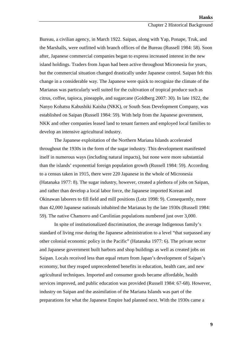
The Japanese exploitation of the Northern Mariana Islands accelerated
throughout the 1930s in the form of the sugar industry. This development manifested
itself in numerous ways (including natural impacts), but none were more substantial
than the islands’ exponential foreign population growth (Russell 1984: 59). According
to a census taken in 1915, there were 220 Japanese in the whole of Micronesia
(Hatanaka 1977: 8). The sugar industry, however, created a plethora of jobs on Saipan,
and rather than develop a local labor force, the Japanese imported Korean and
Okinawan laborers to fill field and mill positions (Lotz 1998: 9). Consequently, more
than 42,000 Japanese nationals inhabited the Marianas by the late 1930s (Russell 1984:
59). The native Chamorro and Carolinian populations numbered just over 3,000.
In spite of institutionalized discrimination, the average Indigenous family’s
standard of living rose during the Japanese administration to a level “that surpassed any
other colonial economic policy in the Pacific” (Hatanaka 1977: 6). The private sector
and Japanese government built harbors and shop buildings as well as created jobs on
Saipan. Locals received less than equal return from Japan’s development of Saipan’s
economy, but they reaped unprecedented benefits in education, health care, and new
agricultural techniques. Imported and consumer goods became affordable, health
services improved, and public education was provided (Russell 1984: 67-68). However,
industry on Saipan and the assimilation of the Mariana Islands was part of the
preparations for what the Japanese Empire had planned next. With the 1930s came a
Hanks
Chapter 2 Historical Background
10
worldwide recession. Japan, as an island nation, had limited natural resources for its
growing industries and increasing population and thus launched a series of expansionist
policies (Lotz 1998: 9).
During the 1930s, the Japanese army assumed an increased influence over
foreign policy. The Western powers became more and more concerned as the
government began moving toward militarism. The U.S. voiced suspicion that the
Japanese Empire was fortifying Micronesian islands sub rosa, directly violating the
League of Nations’ mandate (Lotz 1998: 12). However, the stipulations of the mandate
contained no provisions for inspection of the islands by League officials. To further
suspicions, Japan invaded China in 1932 and unilaterally withdrew from the League of
Nations in 1933, making the Micronesian islands de facto possessions of Japan (Russell
1984: 81). In addition, Japan placed the islands off-limits to foreigners (Carrell 1991:
198). The construction of airfields and oil storage facilities soon increased. The
Japanese government initiated construction of Aslito Airfield on Saipan as early as
1934. By 1940, there was little question about Japan’s military intentions.
Construction of an unmistakably military nature began in early 1941 on Saipan.
Reinforced concrete gun emplacements, communication facilities, ammunition storage
sheds, and radio direction indicators were in the process of being built. In September,
Japan began erecting military barracks, latrines, kitchens, baths, storehouses,
infirmaries, air raid shelters, and torpedo storage sheds on Saipan (Russell 1984: 82). It
was on 7 December 1941 that war arrived in the Pacific. Imperial Japanese Navy planes
delivered a crippling blow to the U.S. Pacific fleet at Pearl Harbor, Hawai’i. The U.S.
military forces were completely unprepared and suffered heavy losses forcing them into
a defensive role until the fleet could be restored. Soon after, Japan claimed victories in
Guam, Hong Kong, Singapore, and the Philippine Islands (Lotz 1998: 9-10).
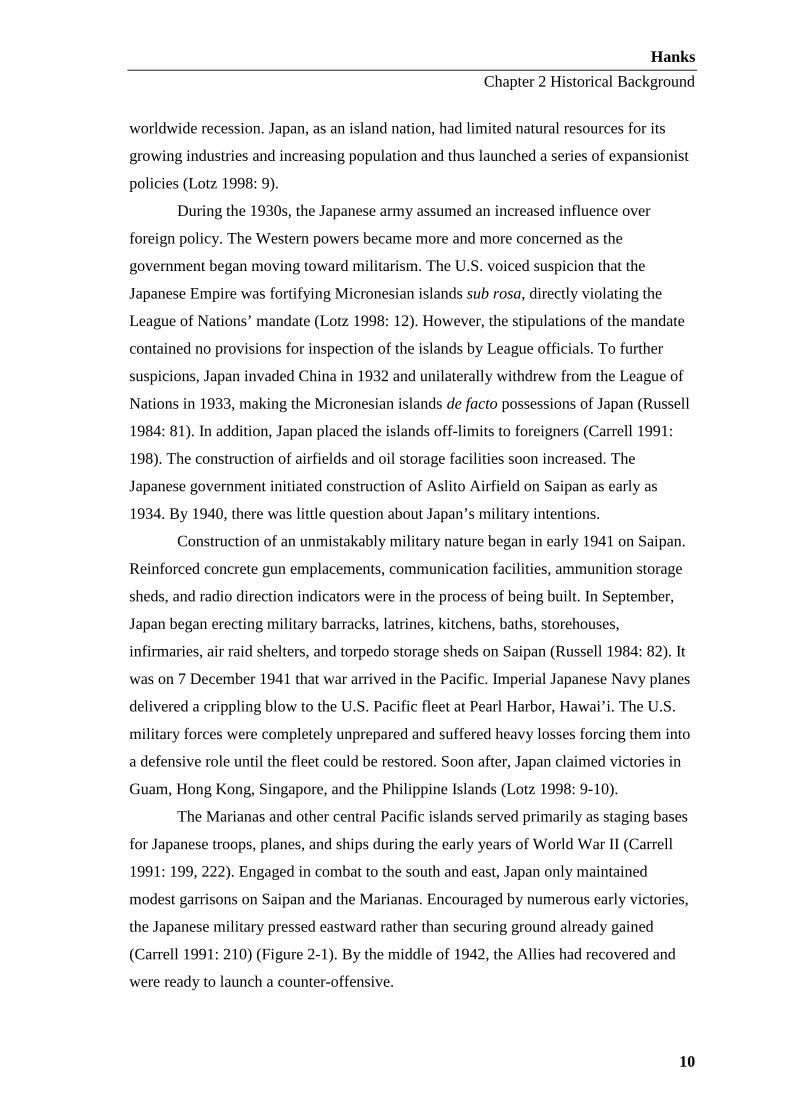
The Marianas and other central Pacific islands served primarily as staging bases
for Japanese troops, planes, and ships during the early years of World War II (Carrell
1991: 199, 222). Engaged in combat to the south and east, Japan only maintained
modest garrisons on Saipan and the Marianas. Encouraged by numerous early victories,
the Japanese military pressed eastward rather than securing ground already gained
(Carrell 1991: 210) (Figure 2-1). By the middle of 1942, the Allies had recovered and
were ready to launch a counter-offensive.

Hanks
Chapter 2 Historical Background
11
Figure 2-1: Map depicting the movement of Allied forces and extent of Japanese occupation in the Far East and the Pacific from 1941-1945. (The Map Database 2009, accessed 5 Sept 2010)
Due to its geographical location and available resources, the U.S. was placed at
the head of the Pacific Theatre against the Japanese. Initial attack plans, known as
“Orange Plans,” involved a systematic seizure and occupation of key Japanese islands
moving from south to north (Crowl 1959: 11). Because of their more northerly location,
the Mariana Islands were not considered in the early plans. These plans quickly
changed, however, with the development of an intimidating new aircraft, the B-29
Superfortress (Figure 2-2).

Hanks
Chapter 2 Historical Background
12
Figure 2-2: Image of a Boeing B-29 Superfortress over Korea. (B-29s Over Korea Webpage 2010, accessed 6 Sept 2010)
Although designed for use in Europe, Allied strategists in the Pacific recognized
the B-29’s potential for inflicting colossal damage on the enemy. “Possessing a range of
approximately 5,600 kilometers, a bomb capacity in excess of four metric tons and
being heavily armed, the Superfortress was indeed a formidable weapon; on which the
U.S. military planners wished to unleash against the Japanese home islands at the
earliest possible date” (Denfeld and Russell 1984: 3). The only hindrance to B-29 raids
was a lack of bases within range of Japan. Being roughly 2,500 kilometers south of
Japan, the capture of Saipan, Tinian, and Guam would place B-29s close enough for
return trips (Denfeld and Russell 1984: 5). Thus, the plans were modified; making the
Marianas a priority after the Marshall Islands campaign was completed.
Battle of Saipan
With the loss of the Marshall Islands in early 1944, Saipan and the Marianas,

Hanks
Chapter 2 Historical Background
13
long considered to be an integral part of the Japanese inner defensive ring, now became
the frontline of Japan’s central Pacific defense. Japanese military leaders suspected U.S.
forces would move on the Marianas and were determined to defend the islands at all
costs. Troops, equipment, and supplies were shipped to Saipan in preparation for the
impending skirmish (Carrell 1991: 246). The Japanese administration even undertook a
massive reorganization of their military command structure in the central Pacific in an
attempt to assure victory (Russell 1984: 84).
The first Allied objective in the Mariana campaign, codenamed Operation
Forager, was the invasion of Saipan. A prodigious force of over 166,000 marine and
army troops (127,000 of which were assault troops) onboard a naval force of more than
535 ships was dispatched to the Marianas Islands (Goldberg 2007: 50). According to
Caporale, Operation Forager “ranks as the Marine Corps’ largest amphibious assault
and the only operation that involved two corps of Marines” (Caporale 1984: 18). Some
71,000 men of the 2nd and 4th U.S. Marine Divisions as well as the 27th Army Infantry
Division were to lay siege upon Saipan on 15 June 1944 (Goldberg 2007: 45). Their
success was dependent upon the outcome of a preemptive bombardment initiative
against Japanese fortifications.
On 11 June, 200 torpedo bombers and carrier-based fighters of Vice Admiral
Mark A. Mitscher’s naval task force began bombarding Saipan from the northeast
(Carrell 2009: 275). Two hundred and twenty-five aircraft launched from over 200
miles away, surprised the Japanese defenders, and destroyed or damaged 147 Japanese
aircraft (Goldberg 2007: 53). Three days of continuous air raids nearly completely
destroyed the Japanese airpower in the Marianas. The primary components of the U.S.
invasion fleet arrived off Saipan on 13 June and commenced pre-landing bombardment
(Lotz 1998: 14). According to Russell, “During the first day of action, seven battleships
and 11 destroyers fired over 15,000 rounds of 16-inch and five-inch shells at military
targets along Saipan’s western coast” (Russell 1984: 88). The 16-inch shells were the
largest ship ammunition the U.S. Navy had at the time at 1.5 meters long and weighing
up to 1,225 kilograms (Carrell 2009: 303) (Figure 2-3).

Hanks
Chapter 2 Historical Background
14
Figure 2-3: U.S. soldier sitting on an unexploded sixteen-inch shell. (Chapin 1994: 27)
On 14 June, other crucial preliminary actions took place along the lower western
coast of Saipan, the primary invasion area, under Operation Forager. Before sunrise,
two Underwater Demolition Teams (UDTs), consisting of 96 men each, set about
demolishing reefs and any enemy mines that might hinder or damage landing crafts
(Goldberg 2007: 55). This region was selected because its sandy beaches stretch nearly
6.5 kilometers. The space would allow the two Marine divisions to land simultaneously.
Additionally, landing along the lower western side would allow the immediate capture
of the airstrip at Chalan Kanoa and consequently place pressure on nearby Aslito
Airfield. Once secured, the airstrips could be strategically employed to support a
penetration northward, as well as eastward, across Saipan. The landing beaches labeled
Red 1, 2, and 3 and Green 1 and 2 were located north of Afetna Point. Green Beach 3,
Blue Beaches 1 and 2, and Yellow Beaches 1, 2, and 3 all lay to the south of the point
(Carrell 2009: 297) (Figure 2-4).

Hanks
Chapter 2 Historical Background
15
Figure 2-4. Saipan invasion beaches June 14-15, 1944. Map design by James W. Hunter III, Ships of Discovery. (Carrell 2009: 298)
The night of 14 June 1944, men of the 2nd and 4th Marine Divisions, under the
command of Lieutenant General Holland Smith, clambered into landing ship tanks
(LSTs) bound for Saipan (Lotz 1998: 14). At 2:00 am on 15 June they loaded into
amphibious tractors, “amtracs,” which began the journey to Saipan’s western coast
around 8:40 am (Russell 1994: 15, Carrell 1991: 249). The Japanese defenders were
ready for them. A series of colored flags were arranged offshore to indicate when U.S.

Hanks
Chapter 2 Historical Background
16
forces entered the range of Japanese shore defenses.
Within minutes of the initial waves of assault vehicles and troops hitting the
beach, over 600 landing craft had made land. Eight thousand U.S. Marines reached
shore in the first 20 minutes (Carrell 1991: 249). Despite encountering heavy enemy
mortar barrages, automatic weapons, and artillery, the Marines were able to secure a
tenuous beachhead ten kilometers in length and nearly 900 meters deep by sundown
(Denfeld and Russell 1984: 9). This allowed the landing of some 20,000 troops by the
end of the first day. According to Lieutenant General Holland Smith, “Our landing was
the most advanced mechanical demonstration we had ever made in the Pacific,” (cited
in Carrell 2009: 307). Although the landings were successful, the Japanese forces
prevented any rapid advance, fighting courageously with any field weapons available.
The first day’s planned advance line took three days to capture (Carrell 1991: 249). This
achievement came at the cost of 2,000 U.S. troops (Carrell 2009: 304). It quickly
became obvious that the Battle of Saipan was going to be costly on both sides.
Awaiting the arrival of the invading Marines were over 32,000 Japanese troops
(double what the U.S. had anticipated) under the overall command of General
Yoshitsugu Saito (Spector 1984: 302). Forty-eight tanks and a complex network of
artillery positions supported the Japanese infantry. The strength of the undersupplied
soldiers was compounded by their commitment to die for the Emperor, if need be. A
force with such a mindset is a formidable one and the ensuing battle proved to be one of
the most brutal in the Pacific Theatre during World War II.
To comprehend the intensity of the fighting on Saipan, it is necessary to
understand the topography and climate of the island. Approximately 22 kilometers long
and eight kilometers across, the topography consists of a central chain of mountains
running north-south on the island (Russell 1994: 1). The mountains yield to a narrow
strip of flat coastal land along the western side paralleled by a reef. Conversely, the
eastern and southern coasts of Saipan are framed by high rocky cliffs, which drop
vertically into the surf. The lowlands were a mess of swamps and sugar cane fields that
not only impeded travel, but also allowed Japanese troops to ambush U.S. troops
(Chapin 1994: 6). Sitting on the latitude 15º 12’N, the tropical marine climate in Saipan
is warm year-round with a wet season from April to October and a dry season from
November to March (Department of Community and Cultural Affairs 2004: 2). Fighting

Hanks
Chapter 2 Historical Background
17
in June, the troops in the Battle of Saipan would have likely been exposed to daily
rainstorms and forced to cope with wet and muddy conditions.
U.S. troops were busy completing objectives on the south end of Saipan until the
end of June. Following the capture of Aslito Airfield and the Naftan Peninsula in the
south, the Allies began pushing north (Lotz 1998: 14). On 2 July 1944, troops of the 2nd
Marine Division were ordered to move into Saipan’s capital city of Garapan. Although
they faced Japanese resistance, the presence of M4 Sherman tanks and amtracs aided the
Marines in securing half the city by nightfall. With Garapan nearly completely secure
by the evening of 3 July, Japanese troops began a retreat to the hills (Russell 1984: 94).
The three U.S. military divisions began moving north on 6 July. Now, with the end in
sight, General Saito called for one final assault. In the early hours of 7 July, roughly
3,000 Japanese troops and nationals, accompanied by five light tanks, assembled for
what was one of the largest banzai charges of World War II (Russell 1994: 24). Several
U.S. battalions were overrun before the charge began to lose momentum. Japanese
casualties numbered nearly 3,000 troops and the U.S. lost 451 with 592 wounded. By
the same evening, much of the ground that had been lost to Japanese forces was
recaptured.
Rear Admiral Richmond K. Turner, the commander of the U.S. amphibious
forces, proclaimed Saipan “secured” on 9 July 1944 (Carrell 2009: 273). The loss of life
in the Battle of Saipan was horrendous. Approximately 3,426 of the 67,451 U.S. troops
who participated in the conflict were killed or reported missing in action. Nearly 12,000
U.S. troops were wounded. The conflict took even greater tolls on Japanese defenders.
Of the 31,629 Japanese troops who fought on Saipan, 29,500 were lost. According to
Japanese sources, however, the total Japanese losses in the Battle of Saipan were
estimated to be in excess of 40,000 (Burns 2008: 18). Such a decisive loss severely
undermined Japanese morale. Humiliated, Hideki Tojo, the Japanese premier and
leading war advocate, resigned on 18 July following the loss of Saipan (Caporale 1984:
18, Carrell 1991: 251). Having captured Saipan, followed by Tinian and Guam, the U.S.
began transforming the islands into airbases in preparation for the arrival of the B-29s
(Lotz 1998: 10).
The strategic location and capture of the Mariana Islands proved crucial to
bringing World War II to a close. Lieutenant General Holland Smith called the Battle of

Hanks
Chapter 2 Historical Background
18
Saipan “the decisive battle of the Pacific offensive” because it “opened the way to the
home islands.” Japanese General Yoshitsugu Saito had written, “The fate of the Empire
will be decided in this one action.” A Japanese admiral agreed, “Our war was lost with
the loss of Saipan” (Chapin 1994: 36).
The M4 Sherman Tank
Of all the major powers, it was the U.S. that neglected the expensive
development of tanks the most during the inter-war recession (Grove 1978: 122). As a
result, the U.S. lacked a modern tank upon entering World War II in 1941. Following
the Japanese attack on Pearl Harbor, a technically simple and reliable medium tank,
modestly labeled “M4,” was put into production posthaste. It was by no means the
finest, most powerful, or well-armored tank serving in the worldwide conflict. However,
since it was accepted as the standard combat tank of the United States military and U.S.
industry was geared for the mass production of the tanks, the strength of the M4s were
in numbers. It is often said, “The M4 Sherman tank was a winner by quantity, not by
quality.” During World War II, the M4 Sherman stood alone as the most prestigious
tank in the U.S. arsenal.
Figure 2-5: Sketch of a base version of a M4 Sherman tank depicting key components. (University of San Diego Webpage 2010, accessed 29 Aug 2010)

Hanks
Chapter 2 Historical Background
19
Approximately 50,000 M4 tanks were manufactured in the U.S. by the end of
World War II (Grove 1978: 123). Designated as a medium tank, Shermans required a
crew of five: the driver, the assistant driver/bow gunner, the ammunition loader, the
gunner, and the tank commander. Despite advances and modifications in later versions
of the M4, the crew remained at five. There were a vast number of Sherman variants,
each with distinctive features, shapes, and modifications. Although each version
differed in appearance (hulls, guns, turrets, armament, etc.), the nomenclature of
Sherman tanks was founded upon the type of engines used to power the vehicle,
production location, and/or fuel type (Grove 1978: 131). Sherman tank variants include:
M4, M4A1, M4A2, M4A3, M4A4, and M4A6. The Canadian Ram tank was assigned
the M4A5 designation and therefore this variant name could not be used in the U.S.
inventory (Grove 1978: 132). Sherman tanks also served in most other Allied forces. It
is interesting to note that the M4 series tanks were christened “Sherman” by the British,
who named their U.S. built tanks after Civil War generals. The designation quickly
caught on with U.S. troops. The U.S. M3 Lee and Grant tanks also obtained their names
in this manner. When employed by the British armored force, M4s became Sherman I,
M4A1s became Sherman II, M4A2s became Sherman III, M4A3s became Sherman IV,
and M4A4s became Sherman V (Grove 1978: 134).
An in-depth discussion of each version of the vehicle would be lengthy and
convoluted. Thus, in an attempt to provide context while maintaining manageability, a
general examination of the M4 models will be discussed below. For a detailed history of
the M4 models refer to World War II Tanks by Grove (1978) or Tanks by Humble
(1977). Welded hulls were used in the M4, M4A2, M4A3, and M4A4 versions, while
M4A1 variants employed a cast hull. A composite hull, consisting of a welded main hull
and cast front hull, were used on the M4 composite model and M4A6 (Humble 1977:
91). The armament aboard Sherman tanks varied throughout the war. The primary
cannon caliber was 75mm, followed by the more powerful 76mm. A 105mm howitzer
was an additional and less common armament option. Cannons were accompanied by
one .50 caliber anti-aircraft gun and two .30-06 caliber anti-personnel machineguns.
Table 2-1 contains the specifications of nine M4 variants.

Hanks
Chapter 2 Historical Background
20
Table 2-1: Comparison of nine M4 Sherman tank variants (Carrell 2009: 487 from Standard Ordnance Catalog, 1944, Vol. 1).
Designation Main Armament Hull Engine
M4(105) 120mm howitzer welded gasoline Continental R975 radial
M4 Composite 75mm cast front, welded sides
gasoline Continental R975 radial
M4A1(76)W n/a cast gasoline Continental R975 radial
M4A2 * 75mm welded diesel GM 6046 (2x6-71 inline)
M4A3W * 75mm welded gasoline Ford GAA V8
M4A3E2 “Jumbo”
75mm (some 76mm) welded gasoline Ford GAA V8
M4A3E8(76)W “Easy Eight”
76mm welded gasoline Ford GAA V8
M4A4 75mm welded gasoline Chrysler A57 (5x6-cyl inline)
M4A6 75mm cast front, welded sides
diesel Caterpillar D200A radial
*Primary types used in the Pacific by the U.S. Marine Corps. during World War II.
A change in hull shape, armor thickness, and ammunition stowage took place at
approximately the time the larger cannons were placed on the M4 tanks. Armor was
thickened from 62mm to 75mm and the armor slope was decreased from 56º to 47º
(Grove 1978: 133, Humble 1977: 89). Ammunition stowage was swapped from dry to
wet as, once in the field, troops quickly recognized that one of the Sherman tanks’
weaknesses were unprotected ammunition lockers. If penetrated, live ammunition in the
dry bins could be punctured by shrapnel, set aflame, and explode. Coupled with the
tanks’ gasoline fuel system, this flaw contributed to the nicknames “Tommy Cookers”
and “Ronson lighters.” To counteract this, U.S. designers developed ammunition
lockers surrounded by a glycol liquid, which diminished the threat of secondary fires
and exploding ordnance (Grove 1978: 132).
The base M4A1 Shermans had a vertical step of 60 centimeters and was capable
of crossing trenches up to 2.26 meters across and fording 90 centimeters of water
(Grove 1978: 130). For the specifications of the basic M4 model, refer to Table 2-2
below.

Hanks
Chapter 2 Historical Background
21
Table 2-2: Specifications of a base model M4 Sherman tank (Grove 1978: 130).
Weight 30.2 metric tons
Length 5.84 meters
Width 2.66 meters
Height 2.74 meters
Crew 5 (commander, gunner, loader, driver, co-driver)
Operational Range 185 kilometers, 662.4 liters
Speed 40-kilometer per hour
As a standard and mass-produced weapon, the M4 tank was a versatile vehicle.
Sherman tanks could be fitted with R3 flamethrowers or dozer attachments and were
even used to lay bridges. The M4 chassis served as the platform for several derivative
armored vehicles such as minesweepers, tank destroyers, self-propelled artillery, and
tank retrievers (Macksey 1971: 226). Another variation featured Sherman tanks
equipped with Duplex Drive (DD) and a propeller for amphibious operations such as D-
Day at Normandy (Macksey 1971: 226).
The stellar service of the Sherman tank earned the vehicle the title of the most
important U.S. tank in World War II. Outside of service in the U.S., Britain, the Soviet
Union, and Israel, the M4 series was also utilized by Australia, India, Brazil, France,
Poland, Pakistan, Egypt, and New Zealand army forces at one time or another (Grove
1978: 138). The M4 Sherman served in the U.S. military from 1942 until 1955.
Sherman Tanks in Saipan
Relative to Europe, a rather small proportion of M4 Sherman tanks were shipped
to the Pacific Theatre. Due to the nature of the war in the Pacific, few tank battles were
fought with Japan. The Japanese forces never deployed many tanks because their
operations were primarily either amphibious or close combat where tanks played a
limited role (Macksey 1971: 166). As the Japanese military seldom used any armor
heavier than light tanks, Sherman tanks fared better against these than against the more
robust European Axis tanks. When facing off against the Japanese Type 95 Ha-Go light
Hanks
Chapter 2 Historical Background
22
tanks and Type 97 Chi-Ha medium tanks, even the Sherman’s early 75mm main gun led
to Allied dominance against the Japanese tank designs. From the outset of the war,
Japanese tanks floundered behind their naval and air technologies and never caught up.
Similarly, Japanese anti-tank weapons were not on par with German weaponry. The
Japanese resorted to innovative and effective anti-tank techniques including mines made
from torpedoes.
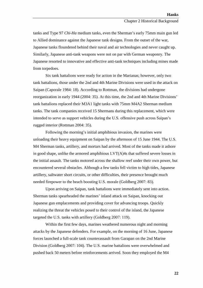
Six tank battalions were ready for action in the Marianas; however, only two
tank battalions, those under the 2nd and 4th Marine Divisions were used in the attack on
Saipan (Caporale 1984: 18). According to Rottman, the divisions had undergone
reorganization in early 1944 (2004: 35). At this time, the 2nd and 4th Marine Divisions’
tank battalions replaced their M3A1 light tanks with 75mm M4A2 Sherman medium
tanks. The tank companies received 15 Shermans during this replacement, which were
intended to serve as support vehicles during the U.S. offensive push across Saipan’s
rugged interior (Rottman 2004: 35).
Following the morning’s initial amphibious invasion, the marines were
unloading their heavy equipment on Saipan by the afternoon of 15 June 1944. The U.S.
M4 Sherman tanks, artillery, and mortars had arrived. Most of the tanks made it ashore
in good shape, unlike the armored amphibious LVT(A)4s that suffered severe losses in
the initial assault. The tanks motored across the shallow reef under their own power, but
encountered several obstacles. Although a few tanks fell victim to high tides, Japanese
artillery, saltwater short circuits, or other difficulties, their presence brought much
needed firepower to the beach boosting U.S. morale (Goldberg 2007: 83).
Upon arriving on Saipan, tank battalions were immediately sent into action.
Sherman tanks spearheaded the marines’ inland attack on Saipan, knocking out
Japanese gun emplacements and providing cover for advancing troops. Quickly
realizing the threat the vehicles posed to their control of the island, the Japanese
targeted the U.S. tanks with artillery (Goldberg 2007: 119).
Within the first few days, marines weathered numerous night and morning
attacks by the Japanese defenders. For example, on the morning of 16 June, Japanese
forces launched a full-scale tank counterassault from Garapan on the 2nd Marine
Division (Goldberg 2007: 104). The U.S. marine battalions were overwhelmed and
pushed back 50 meters before reinforcements arrived. Soon they employed the M4

Hanks
Chapter 2 Historical Background
23
tanks and antitank bazookas, turning the tide of the skirmish. The Japanese tank attack
set the tone for the following night as well. “The Japanese continued to attack, often
fruitlessly, and suffered high losses, while the marines took high but ever-decreasing
casualties” (Goldberg 2007: 104).
The night of 16 June and early morning of 17 June saw another attempt by
Japanese troops to stop the U.S. forces. The 2nd Marine Division received
counterattacks throughout the night with more than 500 Japanese troops and 30 tanks
attacking U.S. positions (Goldberg 2007: 104). Nonetheless, the Marines were better
prepared with more tanks, 75mm guns, rocket launchers, and artillery shells being
continuously brought ashore. After a short 45 minutes, “the largest tank battle of the
Pacific War up to that time” was over and 29 of the Japanese tanks had been destroyed
(Goldberg 2007: 106). The M4 Sherman made its presence known on Saipan.

Hanks
Chapter 3 Literature Review
24
CHAPTER THREE
LITERATURE REVIEW
The purpose of this chapter is to provide a summary of archaeological research
conducted on World War II tanks internationally. Next, Commonwealth and Federal
legislation is discussed as it applies to Saipan’s submerged cultural heritage, as it is
integral to comprehend the legal facets of historic preservation if a monitoring plan is to
be successfully implemented. A summary of the previous historic preservation plan
developed by the CNMI Historic Preservation Office (HPO) will then be provided.
Finally, publications considering heritage tourism in the Mariana Islands and
Micronesia, as a whole, will be addressed.
World War II Tank Archaeology
With a conflict as far-reaching and fully mechanized as World War II, it is not
surprising that remnants of machinery and weapons employed in battle are still being
discovered over 60 years later. Whether plowing fields, digging foundations for
construction, or beachcombing, unexploded ordnance, human remains, and vehicles are
unearthed every year. Battle-scarred tanks from World War II have been located in the
Philippines, Chuuk State, Estonia, France, and elsewhere in Europe and the Pacific.
Unfortunately, few of these tanks have undergone intensive archaeological study in situ,
and their removal has resulted in lost data and information.
Soviet, German, British, Japanese, and American tanks have been found by
locals in fields, forests, lakes, rivers and bogs. Although sometimes reported to the
government for archaeological investigation, civilian relic hunting frequently results in
the tank being removed from its archaeological and historical context. For example, in
September 2009, a U.S. M4A1 Sherman tank was accidentally discovered by a dredging
company near the mouth of Pasig River in Manila Bay, Philippines. The tank was
resting in five meters of water before being extracted by the Philippine Coast Guard
(Army Times Webpage, accessed 23 Aug 2010) (Figure 3-1).
Chuuk State, now a part of the Federated States of Micronesia (FSM), is home to

Hanks
Chapter 3 Literature Review
25
the well-known Truk Lagoon. Located approximately 950 kilometers southeast of
Guam and nearly 5,400 kilometers southwest of Hawai’i, Chuuk was the headquarters
of the Japanese Imperial Navy’s Fourth Fleet. However, in February 1944, the U.S.
launched a devastating two-day attack on the fleet sending hundreds of ships, tanks, and
aircraft to the bottom of the Lagoon (Figure 3-2). This wreckage comprises the world’s
largest intact assemblage of World War II wrecks and is a renowned tourist attraction.
Figure 3-1: U.S. M4A1 Sherman tank being inspected by a member of the Philippine Coast Guard after removal from Manila Bay. (Army Times Webpage 2009, accessed 23 Aug 2010)
Figure 3-2: Japanese Type 97 Chi Ha light tank resting at a depth of 120 feet on the deck of the Nippo Maru. (Dive Gallery Webpage 2010, accessed 23 Aug 2010)

Hanks
Chapter 3 Literature Review
26
In 2003, members of the community salvaged a Soviet World War II KV-1
(Klemeni Voroshilov) heavy tank from the Neva River outside St. Petersburg (Figure 3-
3). Relic hunters extracted another Soviet World War II tank, a T-34-76 “Sniper,” from
a freshwater bog in the Pskov region in the same year. Additionally, local authorities
sanctioned the removal of a Soviet T34/76A tank with German markings by a Komatsu
D375A-2 bulldozer from a lake near Johvi, Estonia in 2000 (English Russia Webpage,
accessed 23 Aug 2010). The T34 was in superb condition, free of corrosion, due to
resting 56 years at a depth of seven meters under three meters of peat. On the surface,
the German markings allowed researchers to determine the Soviet tank had been
captured, but was later abandoned as a result of fuel shortages in 1944 (English Russia
Webpage, accessed 23 Aug 2010). Plans are underway to fully restore the T34 and
display the vehicle at a war history museum.
Figure 3-3: Soviet KV-1 heavy tank being extracted from the Neva River outside St. Petersburg in 2003. (Around St. Petersburg Webpage 2010, accessed 23 Aug 2010)
The English Channel is another location with a relatively high concentration of
submerged World War II tanks. Two British Centaur CS IV tanks, complete with 95mm

Hanks
Chapter 3 Literature Review
27
howitzers, have been located on the seabed in Bracklesham Bay, West Sussex, at a
depth of 20 meters (British Sub Aqua Club Webpage, accessed 23 Aug 2010). A team
composed of Southsea Sub Aqua Club (SAC) members spent five days in July 2010
surveying the sites. Teams of 12 divers took measurements, photographs, and video of
the sites to record the location, orientation, and condition of the vehicles. The Southsea
SAC investigation has produced data that indicates the tanks may have been lost from a
landing craft tank (LCT) while crossing the Channel; a hypothesis supported by
historical Royal Marine and Naval Diaries (British Sub Aqua Club Webpage, accessed
23 Aug 2010). Experts at the Bovington Tank Museum have positively identified the
tanks as Centaur CS IVs from the underwater photographs and video. These tanks are
known as the type used exclusively by the Royal Marine Armoured Support Group for
Operation Overlord, the largest invasion force ever assembled.
Operation Overlord was the initial phase of the Allied invasion of continental
Europe beginning on 6 June 1944. By the end of May 1944, the Allies had mustered
nearly 2,000,000 troops made up of 14 British divisions, 20 U.S., three Canadian, one
French, and one Polish division to take the beach at Normandy, in German occupied
France (Hastings 1984: 46). Accompanying them were 8,000 support aircraft, 4,000
landing craft, 3,500 amphibious vehicles, and 284 major warships (Van der Vat 2003:
15). The invasion was set into motion the day before with the launch of Operation
Neptune, the naval aspect of Overlord. On that day, the largest armada the world had
ever seen approached Normandy’s beaches, which were known to Allied troops as Utah,
Omaha, Gold, Juno, and Sword (Van der Vat 2003: 80). Because of its magnitude, D-
Day is one of the most researched and studied events in recent history.
In 1997, Brett Phaneuf and Robert Neyland recognized an area of the invasion
lacking research, the bottom of the English Channel. A substantial number of tanks
were lost to the ocean during the D-Day crossing. Backed by the Institute of Nautical
Archaeology at Texas A&M University (INA) in cooperation with the Naval Historical
Center’s Underwater Archaeology Branch, Phaneuf began the first detailed underwater
investigation of the waters off Omaha beach in 2000 (D-Day: The Untold Story 2000).
Remote sensing surveys off the coast identified 13 Duplex Drive (DD) tanks.
DD tanks were U.S. M4 Sherman tanks that had been outfitted with twin propellers and
an inflatable canvas skirt designed to keep all 32 metric tons afloat (Figure 3-4). Duplex

Hanks
Chapter 3 Literature Review
28
Drive tanks were specifically designed for taking the French beachhead on D-Day.
Launched over 6,000 meters from the beach, these weapons maintained the element of
surprise. The canvas doubled as a mask that gave the tanks the appearance of rubber
rafts motoring toward the beach at an unimpressive 6.5 kilometers per hour (D-Day:
The Untold Story 2000). Once in the surf zone, the DD Shermans dropped the canvas
skirts and fired upon enemy strongholds at close range (Figure 3-4).
Figure 3-4: DD Sherman tank afloat with canvas screen up during testing (top) and onshore with screen down (bottom) during testing. (Lone Sentry Webpage 2010, accessed 23 Aug 2010)

Hanks
Chapter 3 Literature Review
29
The tanks of interest to Phaneuf belonged to the 741st tank battalion (D-Day:
The Untold Story 2000). The 29 Duplex Drive tanks in the battalion were to land on
Omaha beach and lay down cover fire for the following infantry. Of the 29 tanks
deployed, 27 were swamped by heavy seas. All 28 DDs bound for neighboring Utah
beach made it ashore, so the research question remained: What had happened on the
way to Omaha?
One goal of Phaneuf’s research in 2000 was to determine the location of landing
craft, artillery, ships, ordnance, and other equipment from Operation Neptune. The sites
were mapped and entered into the Geographic Information System (GIS) to allow for an
analysis of the distribution of tanks on the seabed.
Figure 3-5: Allied troops wade ashore on Omaha beach on D-Day, 6 June 1944. (Keep Your Helmet On Webpage 2009, accessed 24 Aug 2010)
Historical accounts suggest the rough seas on D-Day sent the tanks of the 741st
straight to the seafloor, but their positions suggest they made it much farther than
initially believed. Some covered more than three kilometers before going down. The

Hanks
Chapter 3 Literature Review
30
tanks’ orientation on the seabed reveals why they finally sank. Having found 23 of the
27 submerged tanks, Phaneuf recognized that they are all pointing at a landmark that
could be seen from the water, the steeple of the church at Colleville sur Mer (D-Day:
The Untold Story 2000). Phaneuf believes the steeple may have been a navigation
landmark and/or rendezvous point. Being pushed by the powerful currents running
parallel to Omaha beach, the tank crews adjusted their course to fight the current and
keep their bows pointed at the steeple. This orientation subjected the more fragile,
flexible, long side of the inflatable canvas to the six-foot waves in the channel, which
crushed the skirt, flooding the tanks and sending them to the bottom. If the tanks had
continued straight into shore, keeping the waves at their stern, they may have made it to
land. According to Phaneuf, “that they launched at all is a testament to the courage and
determination of the Allies, in the face of daunting odds and grave danger” (D-Day: The
Untold Story 2000).
World War II tanks are still being located on a regular basis over 60 years after
the war ended. As vehicles from the most profound global skirmish to date, each tank
has a relevant story to tell. Removal from their original context is not the best way to
record the information the historic vehicles have to offer. Furthermore, without
adequate funding, proper conservation, and maintenance, the tanks quickly deteriorate.
Systematic archaeological surveys and mapping, coupled with in situ preservation
provides for the tanks’ story to be shared while avoiding the challenges linked to
extraction.
Applicable Legislation
After Japan’s defeat in 1944, the Marianas were administered by the U.S. as part
of the United Nations Trust Territory of the Pacific Islands. This meant defense and
foreign affairs became the responsibility of the U.S. In the 1970s, the people of the
Northern Mariana Islands decided against pursuing independence, but instead chose to
forge closer ties to the U.S. Negotiations for territorial status began in 1972 and a
covenant to establish a commonwealth in political union with the U.S. was approved in
1975 (Department of Community and Cultural Affairs 1996: 2). It was not until 3
November 1986, however, that the covenant was fully implemented. The CNMI
government adopted a new constitution in 1977 and the constitutional government took

Hanks
Chapter 3 Literature Review
31
office the following January. Under the stipulations of the covenant, U.S. federal law
applies to the CNMI. Understanding this, the CNMI’s cultural and historic resources are
afforded protection under U.S. Federal laws and regulations. The primary Federal
legislation applying to the CNMI’s heritage is Section 106 of the National Historic
Preservation Act of 1966 and the associated 36 CFR Part 800 as well as the Abandoned
Shipwreck Act of 1987 and Sunken Military Vehicles Act (Department of Community
and Cultural Affairs 1996: 2).
The National Historic Preservation Act established a national historic
preservation program and set up state historic preservation offices. This statute also
created the United States National Register of Historic Places (Department of
Community and Cultural Affairs 1996: 8). Maintained by the National Park Service, the
National Register is a formal listing of the most significant resources within the U.S.
including objects, sites, districts, buildings, and structures. Section 106 obliges federal
agencies to be mindful of the effects projects may have on sites eligible to be or already
listed on the National Register of Historic Places. Section 106 is significant in that is not
only requires a review of federally funded infrastructure projects such as schools, roads,
and utilities, but any project requiring a federal permit (Department of Community and
Cultural Affairs 1996: 2).
Entitled “Protection of Historic Properties,” 36 CFR Part 800 outlines in detail
the Section 106 review process which ensures the identification, evaluation, and
protection of historic and cultural resources. The identification phase determines
whether or not resources are present within a project area. Identification may involve
archaeological surveys, archival research, consultations with HPO, or any combination
of the three (Department of Community and Cultural Affairs 1996: 5). If historic
resources are identified, the evaluation step determines their significance. A site is
considered significant if it meets one or more of the National Register criteria:
• The resource has yielded or may be likely to yield information significant to
the history or prehistory of the Mariana Islands.
• The resource is associated with the lives of persons significant to the
Marianas’ past.
• The resource possesses distinctive characteristics of a type, period or method
of construction, characteristics that represent the works of a master, possess

Hanks
Chapter 3 Literature Review
32
high artistic values, or significant distinguishable entities whose components
may lack individual distinction.
• The resource is associated with the events that have made a significant
contribution to the broad patterns of Mariana Island history (Department of
Community and Cultural Affairs 1996: 5).
The third phase involves determining the magnitude of the effects a project will have on
significant historic resources. The scale utilized by the Division of Historic Preservation
(DHP) ranks impacts as no effect, no adverse effect, or adverse effect. If the project is
likely to have an effect on the resource, consultations between the developer and
Historic Preservation Officer will be initiated to discuss either in situ preservation or
mitigation methods as a means of rectifying the situation. Mitigation measures include
relocation, data recovery, monitoring, backfilling, interpretive development, and/or
intensive recording (Department of Community and Cultural Affairs 1996: 6). However,
the proper method is dependent upon the project activities, location, individuals, cost,
and other variables.
The Abandoned Shipwreck Act of 1987 holds that any wreck, determined as
being abandoned, that lies embedded in or on a state’s submerged lands is property of
that state and subject to the state’s jurisdiction. Over the years, the Act has come under
attack and been the root of numerous court cases based on claims of ambiguous
wording. The Act does not include military wrecks, as they are owned by their
commissioning nation.
The Sunken Military Vehicles Act establishes a preservation of ownership to
sunken military craft (i.e. warships, naval auxiliary, military aircraft, and military
spacecraft) and associated contents regardless of when the vessel sank. The Act also
prohibits the possession of a sunken military craft and any activity directed at a sunken
military craft that disturbs, removes, or injures any vehicle unless authorized by permit.
However, this legislation is difficult to regulate. According to Martin McAllister (pers.
comm., 2010), when the Act went into effect in 2005, the regulation for the Act had not
yet been written, creating a piece of legislation that was unable to be enforced.
In addition to Federal laws, the Commonwealth legislature passed the Historic
Preservation Act of 1982, also known as Public Law 3-39, to safeguard historic
resources of cultural and scientific significance. This law offers protection to important

Hanks
Chapter 3 Literature Review
33
archaeological, historic, cultural, and architectural sites on both public and private lands
throughout the CNMI (Department of Community and Cultural Affairs 1996: 2). Public
Law 3-39 also created the Division of Historic Preservation.
The CNMI HPO operates under the DHP as a part of the Department of
Community and Cultural Affairs (DCCA). It is the responsibility of the HPO to uphold
and enforce both Commonwealth and Federal statutes as well as manage funding
allocated for historic preservation. HPO receives federal assistance from the Historic
Preservation Fund grant from the U.S. Department of the Interior, National Park Service
and annual appropriations made by the Commonwealth legislature to be applied to the
identification and protection of historic properties (Department of Community and
Cultural Affairs 2004: 13). The HPO’s chief activities can be categorized into several
areas including survey, site registration, project review, public education, and cultural
preservation. To carry out these tasks, Saipan’s HPO is staffed with a Federal Grant
Manager, Historic Preservation Officer, Historic Preservation Coordinators, and
professionals in the fields of history and archaeology totaling ten personnel.
It is the belief of HPO staff that the integration of historic preservation into
project designs will bolster development (Department of Community and Cultural
Affairs 2004: 13). Consultations with the HPO early in the planning process are a
catalyst for success. DHP acknowledges that development in the CNMI is a priority and
is willing to assist developers while simultaneously protecting irreplaceable historic
resources (Department of Community and Cultural Affairs 1996: 8). Further, they hold
that the protection of significant historic and cultural resources and modern
development are not mutually exclusive activities.
CNMI Historic Preservation Plan
Preservation sentiments are phenomenal, but remain meaningless unless put into
motion. To convert ideas into action, DHP and its partners spent a year devising the
“CNMI State Historic Preservation Plan, 2004-2008.” The intent of the plan was to
guide the Commonwealth’s heritage management and monitoring program for the next
four to five years. A list of goals for historic preservation in the Marianas was
developed, objectives to achieve these goals were outlined, and potential challenges
were addressed within the Preservation Plan. The goals and objectives will be discussed

Hanks
Chapter 3 Literature Review
34
in this section, while the challenges and counteractions will follow in Chapter Five.
Before expanding on the aims discussed within the preservation plan, it is
important to understand DHP’s motivation behind these. DHP holds that, “Historic
resources not only serve as important links with the islands’ past, but it possesses the
potential to significantly expand our knowledge regarding prehistory and history; they
also are resources with considerable economic potential” (Department of Community
and Cultural Affairs 2004: 1). DHP desires to preserve the Commonwealth’s cultural
resources because they recognize the potential to add to our understanding of past
human activities on the Mariana Islands as well as contribute to the livelihood of island
residents. Maintaining equilibrium between preservation and realizing economic
potential relates to the primary research question of this thesis, what issues and
challenges are involved in the heritage management of submerged sites where public
involvement is encouraged through heritage tourism?
The goals laid out by DHP in the 2004-2008 Preservation Plan were initiated to
counterbalance human pressures on historic sites and include:
• Expanding the existing funding base for historic preservation programs in
addition to pursuing more dependable, long-term funding sources to support
projects and activities.
• Ensuring that preservation planning is a routine part of all environmental,
land-use, and public policy activities.
• Stimulating the local economy by integrating historic preservation activities
into policies and projects that support and invest in the tourism industry and
local communities.
• Increasing opportunities for and encouraging the general public to participate
in historic preservation projects, events, and activities.
• Expanding public appreciation for and understanding of the CNMI’s rich
history through education and outreach programs.
• Increasing and strengthening relationships with federal agencies, to
encourage collaborative endeavors to protect significant historic resources
(Department of Community and Cultural Affairs 2004: 34-39).

Hanks
Chapter 3 Literature Review
35
Heritage Tourism in the Mariana Islands
The natural and cultural resources of a specific destination are what set it apart
from other locations. It is these factors that are capitalized on in all forms of tourism.
“The concept of heritage eco-tourism is to go beyond this and inspire an appreciation
and to educate people about its value,” (Spennemann et al. 2001a: 31).
Cultural heritage tourism is on the rise. Museums, sites, and traditional festivals
are drawing tourists to cultural attractions around the globe. Heritage eco-tourists are
generally attracted to the rarity and significance of particular cultural sites. Perhaps due
in part to the prefix, eco-tourism is commonly held to be “softer” on the cultural and
natural resource than mainstream tourism (Spennemann et al. 2001a: 31). However, the
fragility, vulnerability, and significance of the resources may make the sites more
susceptible to the threats of visitor impacts. Even if heritage tourism is not encouraged,
impacts on prominent and renowned sites, such as those on Saipan, will continue.
Worse yet, if left unmanaged, the severity of potential impacts may increase.
According to Spennemann et al. (2001a: 30), the development of heritage
tourism opportunities worldwide has left Micronesia the last largely unassessed region.
In 2000, the CNMI HPO and the U.S. National Park Service organized a symposium for
the purpose of discussing methods of developing sustainable heritage tourism in
Micronesia. A majority of the attendees were heritage managers, people involved in the
tourism industry, and parks and wildlife staff. Participants traveled to Rota from islands
in the CNMI, the Federated States of Micronesia, the Republic of Palau, and Hawai’i.
Upon arriving, attendees were polled concerning their knowledge of heritage tourism
and their expectations regarding the management of Micronesian environmental and
cultural resources (Spennemann et al. 2001a: 30). Nearly 64% of respondents agreed
with the statement that heritage tourism does not exist as a bona fide industry, but is a
portion of the overall tourism industry. In spite of this, 91.6% also agreed that heritage
tourism is more than a popular trend and has a remunerative future (Spennemann et al.
2001a: 31). Of ten options provided in the survey, archaeological sites were ranked as
having the highest perceived tourism potential, although it is possible that the outcome
was biased by the nature of the symposium and occupations of the respondents. Non-
Indigenous heritage locations (e.g. World War II sites), ranked the poorest in terms of
their potential for promoting eco-tourism. As stated by Spennemann et al., “the fact that

Hanks
Chapter 3 Literature Review
36
non-Indigenous heritage sites, and in particular WWII sites ranked so poor may be due
to the negative perception of the war by the local population” (2001a: 32).
Western styles of cultural preservation tend to focus on tangible heritage while
Micronesians display a preference for non-tangible heritage (e.g. traditional skills and
knowledge) (O’Neill and Spennemann 2001: 46). According to Spennemann, some
have argued that World War II remains are left to deteriorate by the Indigenous
Micronesian populations who do not care about them or at least were not concerned
about them in the past. The obvious question not raised is: Why should islanders care to
begin with? With few exceptions, the Pacific Islanders were not actively involved in the
War. According to Spennemann (1992: 15),
It happened around them; it happened against them. Their islands were bombed and burned; their gardens burned by napalm or destroyed by tanks plowing through them; their villages shelled by naval vessels and canoes sunk by aircraft; the islanders themselves were commandeered for forced labor, experienced food shortages and starvation.
World War II in the Pacific, a momentous event in world history from a Western and
Eastern perspective, is simply a brief interlude from the Indigenous Pacific islanders’
point of view (Spennemann 1992: 15). This view, though pragmatic, has the potential to
hinder the effective preservation of non-Indigenous heritage resources if ignored.
O’Neill and Spennemann argue that efficacious preservation of cultural
resources is dependent upon several factors: political will, community interest, and
availability of various resources (2001: 46). Saipan struggles in each of these arenas.
An upsurge in the CNMI’s heritage tourism industry will undoubtedly stimulate the
local economy, attracting visitors and drawing money to the islands. However, the
connection between economic gain and heritage preservation is precarious one as it
subversively suggests that sites which are unsuitable for tourism development are less
worthy of protection and can therefore be neglected (Spennemann 2003: 51). In
addition, heritage sites are vulnerable resources and may be harmed by tourism
activities. According to Carrell, “developing tourism operations of the CNMI could
cause heavy visitation to these sites by scuba divers. There is already a commercial tour
submarine on Saipan that offers tours of some underwater sites. There have been reports
of this tour submarine damaging some of the sites” (1991: 335).

Hanks
Chapter 4 Methodology
37
CHAPTER FOUR
METHODOLOGY
The purpose of this chapter is to introduce and outline the methodology
employed in this research. The first section of the chapter elucidates the research
methodology employed to obtain historical and contextual data. The way in which
information on applicable legislation and management plans was systematically
reviewed can also be found in the first section. Next, it will outline previous work
carried out on Saipan’s M4 Sherman tanks. This will be followed by a detailed
description of how the data was collected on site. Finally, the chapter will close with the
limitations to the methodology to better inform future research efforts.
Research Methods
Archival Research
Historical research for this project was conducted in Adelaide, South Australia
and Saipan. Research was focused on gaining an understanding of the Battle of Saipan,
specifically the amphibious invasion, as well as a background and use of M4 tanks in
World War II. Sources were obtained from the American Memorial Park, HPO, and
DHP on Saipan. The Flinders University Library and the State Library of South
Australia were visited in Adelaide. These libraries provided photographs, primary and
secondary historical works, as well as articles relating to the battle, Sherman tanks, and
cultural heritage management.
In addition, HPO provided several sources that aided in unraveling relevant
legislation as it applies to the CNMI’s cultural resources. Other sources from the office
illuminated the role of HPO in light of the legislation and offered an understanding of
DHP’s 2004-2008 Preservation Plan. Through an examination of these materials,
strengths, weaknesses, and challenges were identified. The review of the legislation and
previous management plans is imperative to the development of a realistic and
sustainable monitoring plan for Saipan’s submerged resources.

Hanks
Chapter 4 Methodology
38
Personal Communication with HPO Heritage Officers
While in Saipan, the author had the opportunity to speak with Ronnie Rogers
and John Palacios of HPO about current issues regarding the management of submerged
cultural resources, legislation, and HPO’s future objectives. The information gathered
through those conversations was illuminating and played a major role in shaping the
cultural heritage monitoring plan discussed in detail in the Chapter Six. A copy of
consent to use conversations with staff is provided in Appendix I.
Previous Work on M4 Sherman Tanks
Before Flinders University began collaborative archaeological work with
CNMI’s HPO in 2007, a vast amount of data had been collected in Saipan’s Tanapag
and Garapan Lagoons by other agencies and organizations. A series of geophysical and
visual surveys revealed a plethora of sites in the island’s coastal waters. As one might
expect, the magnetic anomalies detected through magnetrometry were predominantly
linked to the Battle of Saipan.
The Pacific Studies Institute on Guam conducted the first survey in 1979 and
1980 under contract to the U.S. Army Corps of Engineers Pacific Ocean Division
(Burns 2008a: 24). Diver and visual inspections, coupled with literature reviews,
included the channel west of Garapan and reef flat north of the Fishing Base Dock.
Objects onshore and in the water from the Japanese, World War II, and U.S. occupation
periods were identified and documented. No reference to the tanks was made.
Four assessment surveys were carried out by the War in the Pacific National
Historical Park (WAPA) submerged-research team in the Saipan Lagoon between 1983
and 1990 (Carrell 1991: 329). The National Park Service and Pacific Basin
Environmental Consultants (PBEC) carried out separate surveys in 1983, 1984, and
1985 on submerged sites and World War II remains. However, the only mention of the
Sherman tanks in the 1991 report was, “Two Sherman tanks were discovered during the
1984 survey of Saipan Lagoon. Only partially submerged, they lie about 300 yards from
shore. These are in excellent condition and their turrets can be seen above the high-tide
line from shore” (Carrell 1991: 479). The surveys simply provided a location for two of
the three M4 Shermans along the coast. No archaeological investigations were pursued.
Southeastern Archaeological Research, Inc. (SEARCH) of Jonesville, Florida,

Hanks
Chapter 4 Methodology
39
conducted magnetometer and remote sensing surveys coupled with diver identification
in April and May of 2008. The surveys covered Tanapag and Garapan Lagoons on the
west coast of Saipan. Seven hundred and seventy-eight total magnetic anomalies were
identified within Tanapag Lagoon (Burns 2008a: 87). According to both reports, 88 of
these anomalies were selected for further investigation by sidescan sonar and/or diver
identification or were previously identified.
Magnetic anomalies M490, 491, and 503 occur in a linear cluster and are
associated with the remains of a M4A2 Sherman tank this thesis will refer to as Tank 1
(Burns 2008b: 89). Magnetic anomaly M755 was identified as the remains of another
M4A2 Sherman tank, labeled Tank 2 (Burns 2008b: 98). Tank 3, however, was not
mentioned. It is possible that Tank 3 was outside the search area.
Toni Carrell of Ships of Discovery compiled an extensive and detailed maritime
context of the history and wrecks within CNMI waters in 2009 entitled, Maritime
History and Archaeology of the Commonwealth of the Northern Mariana Islands. This
publication commits a respectable portion of Chapter 13 to describing the history,
manufacture, specifications, status, and position of the M4 tanks found on Saipan
(Carrell et al. 2009). Although somewhat standard information, Carrell’s work contains
a larger section dedicated specifically to Saipan’s tanks than any preceding reports. All
three M4 Sherman tanks are mentioned in Carrell’s report.
Over the last year, teams from Flinders University’s Maritime Archaeology
Program in conjunction with Ships of Discovery have collected data on the tank sites
during two sessions of fieldwork: two weeks in July 2009 and two weeks in February
2010. A third session took place for 2.5 weeks in June 2010. During the work in July
and February, preliminary measurements were recorded, photos taken, initial sketches
made, and basic site evaluations completed. A detailed description of the data collected
in June 2010 will be presented in the following chapter.
Site evaluations were completed by Flinders University personnel in July 2009
and later modified to include additional information gathered in February 2010. Each of
the three tanks was assessed and allotted an individual evaluation consisting of a general
description, location, date visited, natural and cultural features, artifacts, suggested
mooring locations, and future research potential. The depth, environment, visibility,
absence of a current, bottom composition, human and/or environmental impacts,

Hanks
Chapter 4 Methodology
40
potential threats, and associated artifacts were also recorded. Data contained in these
documents will be crucial to the success of future management and monitoring plans as
it provides a basis for comparison. Many of the recorded observations and photographs
taken during previous fieldwork greatly contributed to this research and have been
included in this work.
To ensure the monitoring plan is established on a solid foundation and
effectively employed, it was integral to obtain a sound understanding of the issues and
processes affecting the tanks. The Nautical Archaeology Society lists the following
issues as a guide:
• what material(s) the shipwreck, or tank in this case, is composed of and how
it is distributed;
• what the seabed is composed of and how it is likely to be affecting the wreck
material;
• the biology of the site;
• the water movement on the site (tides, waves, and/or currents);
• the water itself (e.g. pH and salinity); and
• outside factors, such as human activity, which may be affecting the sites
(Bowens 2009: 164).
The data gathered in June 2010 targeted these issues through visual surveys, video, still
photography, and measurements.
Previous Assessment Work in Micronesia
Spennemann’s work in the Mariana Islands and Micronesia has contributed a
great deal to heritage preservation in the Pacific. Through surveys and interviews,
Spennemann strives to gain insight into peoples’ attitudes toward, mindsets on, and
expectations of heritage preservation and tourism. Ranging from government officials,
students, teachers, tourists, and Indigenous populations, the wide scope of
Spennemann’s studies is their strength. In recording peoples’ attitudes toward heritage
tourism and attractions, Spennemann is able to check the pulse of historic preservation.
This data is invaluable to HPOs and other regulatory agencies because it informs staff of
locals’ and tourists’ heritage awareness and motivations for visiting. With this insight,
agencies can assess themselves and adjust.

Hanks
Chapter 4 Methodology
41
In 2007, William Jeffery submitted a thesis outlining his investigation of the
creation of a maritime reserve in Chuuk, Federated States of Micronesia (FSM). The
focus of his work was to explore the use of submerged World War II heritage sites and
the “transformation of ships to shipwrecks through World War II, and then to cultural
heritage sites, war graves, and economically valuable sites” (Jeffery 2007: 7). Another
objective of Jeffery’s work was to evaluate the influences colonialism and the war had
on the Chuukese people. He found that conflicts arose from differing perceptions of
submerged World War II sites in Chuuk Lagoon, as a “response and resistance to
colonialism, the war, and neo-colonialism” (Jeffery 2007: 283). Such evidence is useful
in the interpretation and management of submerged World War II sites in the Pacific,
where, like in the CNMI, Indigenous cultural practices may differ from a more Western
perspective of heritage preservation.
Data Collection
Equipment
An assortment of gear and equipment was employed to collect data during the
fieldwork in June 2010. Two Garmin GPS 12 XLs (WGS 84) were used to record
waypoints and a route along the beach. A waterproof bag was used to get the GPS to the
tanks to record the positions of the vehicles. Three 50-meter tapes, plastic slates,
carpenter’s pencils, and A4 mylar were used to obtain and record data on site. Mesh
bags proved useful in transporting gear and water bottles to the sites. A Canon Digital
Ixus 990 IS, Canon PowerShot A640, and Canon PowerShot A630 were used to
supplement the data recorded manually by scientific photography and create a catalogue
for visual reference. Individuals working on the tanks wore fins, snorkels, and masks to
facilitate the recording of data underwater.
Shoreline Survey
The data gathered in June 2010 included both a thorough archaeological
investigation of each tank as well as a shore-based survey. The shoreline survey was
conducted between Tank 1 and Tank 3 in order to supply GPS waypoints by which
distances to the tanks could be later determined. The presence of resorts, parks,
restaurants, and carparks on the beach were recorded as they increase the accessibility

Hanks
Chapter 4 Methodology
42
of the tanks and likely influence visitor numbers at each site. Routes and waypoints of
significant natural and humanmade features were also entered into ArcGIS so they
could be analyzed in relation to individual tank positions and the coastline. One
significant example is a Japanese gun emplacement, or “pillbox,” located on the beach
near Tank 3. Whether the pillbox and the M4A3 tank engaged one another during the
battle is uncertain, but this cannot be discounted on account of their proximity.
On-site Survey
The data collection methodology was consistent on all three tanks so as to
facilitate comparison. Upon arriving at each site, visual inspections were carried out.
This allowed individuals to become familiar with the M4 tanks, record any general
observations, as well as identify any hazardous flora or fauna. This time was also used
to coordinate a brief visual survey of the area surrounding each tank for loose
components or other objects of interest. Next, GPS positions were recorded on each
tank and bearings of the hulls and gun turrets were taken. A GIS was later used to
incorporate the GPS positions of the tanks and significant features to construct spatially
accurate georeferenced maps of the beach and the location of the tanks. The GPS route
taken along the beach was then imported to GIS with the data from each tank providing
accurate distances.
An integral component of this research was identifying absent features of the
tanks that have been lost to salvage or corrosion over the years. In order to successfully
monitor the tank sites and identify newly missing parts in the future, an inventory was
taken in June 2010. To accomplish this, templates of complete M4A2 75mm and M4A3
75mm tanks were used to sketch a mock site plan onto mylar sheets. Teams then
modified the sketches according to the presence and absence of components. By
knowing what should be on site, individuals were able to identify and designate features
as missing. A thorough use of this technique would also identify any field modifications
to the tanks. Notes on open hatches were included. Missing components are discussed in
detail in Chapter Six.
Visitors and Rubbish
Next, one team worked to record visitors to the tanks as well as photograph
Hanks
Chapter 4 Methodology
43
rubbish in and around the vehicles. Times, modes of transportation, and types of
activities on site were recorded for reference. The frequency of visitors was difficult to
calculate as the presence of researchers on site likely discouraged swimmers and boats
from stopping at the tanks. Visitors to the tanks and passing tour boats were
photographed for reference. Although regular, extended observations would be ideal,
the limited visitor observation time in June 2010 provided a glimpse of the tanks’
popularity and use. As such, this data will be useful in formulating a monitoring plan.
Corrosion/Deterioration
At the same time, a second team worked to identify, photograph, and sketch any
cracks, holes, and/or active corrosion present onto a site plan. The identification of at-
risk components on the tanks and potential threats visitors may pose to the sites are
integral to the success of the proposed monitoring plan. To accomplish this, a
comprehensive photographic record of each site (especially of components in eminent
danger of being damaged or lost) was made. Any protruding components of the tank in
danger of breaking off, as the result of stress fractures and/or corrosion, were recorded
on preliminary site plans. Active corrosion sites on the tanks were also photographed
and sketched. Prominent cracks, holes, and missing elements were photographed to
monitor future deterioration. Photographs are a relatively cheap and easy way to record
sites. It is also manageable with limited staff as one person can visit a site with a
camera. When considered in conjunction with one another, this information will aid in
determining the modern cultural impacts on the sites as well as creating a record for
comparison in the future.
It should be noted that some photographs and data employed in assessing and
mapping the corrosion, deterioration, and at-risk components of the three M4 Sherman
tanks were collected in February 2010. Due to the presence of more cameras at each site
than scales or north arrows, a vast amount of photos were taken without these controls.
However, since most of the dimensions of M4 tanks are well recorded in historical
literature, photographs were chosen based on clarity and area represented. For these
reasons, some images included in this work do not have photo scales or a north arrow.

Hanks
Chapter 4 Methodology
44
Depth Measurements
Another team took depth measurements between the seabed and the water
surface. Depth measurements between the seabed and the water surface were taken to
assess the proportion of the tanks that is repetitively inundated and exposed with tidal
fluctuations. Over time, this information can also be utilized to determine how much of
the tanks become buried or uncovered by shifting sands. Eight depth measurements
were taken on each tank: one at the centre of the bow, one at the centre of the stern, one
at each corner of the vehicle, one in middle of the starboard side, and one in the middle
of the port side. This data was recorded on a preliminary sketch of the site.
Vegetation
The extent of vegetation, primarily seagrass and seaweed of genus caulerpa,
surrounding each tank was measured. This methodology was more improvised than
other aspects of data collection due to a dependence upon the abundance of vegetation
surrounding the tanks. Standing in the center of the tank’s turret, one team member held
the zero end of the tape while another swam out to the sand/vegetation interface. The
individual on the tank then took a bearing of the tape and recorded the distance reported
by the team member in the water. This procedure was repeated approximately every 10º
to complete a 360º perimeter (Figure 4-1).
Figure 4-1: Team members pulling the tape taut to measure the distance to peripheral vegetation. (Flinders University, photo by A. Legra, 2010)

Hanks
Chapter 4 Methodology
45
Active corrosion, tides, and vegetation all offer clues to natural impacts on the tanks.
The measurements taken of vegetation and the depth surrounding each M4 Sherman can
also be coupled with historical accounts to investigate theories as to how the tanks came
to be where they are today.
Limitations in the Methodology
Although a great deal of relevant data was collected in June 2010, a couple of
limitations presented themselves in the field. The inability to test active corrosion or
determine the extent of deterioration hindered the potential to estimate how long the
sites will last in their current condition. To achieve this objective, specialized equipment
is needed. Obtaining and transporting a digital multimeter and pH meter to Saipan
would have been difficult in June 2010, but is suggested for future research and
monitoring. Another constraint that arose was limited time to observe visitor activities.
Due to the limited amount of space on the tanks, no swimmers or visitors approached
the M4 Shermans during investigations. As most swimmers escape the afternoon heat
and pass their lunch breaks in the water, late morning to early afternoon observation
time would be ideal for discerning the typical visitor activities. This would allow a
record of frequency.

Hanks
Chapter 5 Data Analysis
46
CHAPTER FIVE
DATA ANALYSIS
This chapter serves to present the data collected on the three M4 Sherman tanks
in June 2010. The first portion of the chapter will shed light on the environment,
orientation, location, and identity of the three tanks located in Garapan Lagoon on the
western side of Saipan. The next section provides the data collected and information
specific to each tank. Tables, photographs, and site plans illustrating the depth
measurements, observations of site visitors, surrounding vegetation, and at-risk
components of the tanks will be presented. In addition, images of prominent cracks,
holes, corrosion, and rubbish will be shared. Finally, the information gathered through
personal communication with Ronnie Rogers and John Palacios of the CNMI Historic
Preservation Office (HPO) will be discussed. Their views on current preservation
policies and major management challenges are put forward and considered. Finally, the
chapter closes with the presentation of HPO’s future management objectives.
Saipan’s Shermans: Site Locations and Description
General Location
All three tanks are partially submerged on a shallow, flat, fine sandy substrate
inside the barrier reef. These sandy areas are interspersed with patches of various
seagrass species. Oleai and Susupe beaches lay east of the tanks and the shoreline runs
roughly north-south (Figures 5-1 and 5-2). Due to their proximity to the beach,
swimmers often use the tank sites as a course for a “tank swim,” fishing or dive
platforms, or picnic tables. Unfortunately, unsightly rubbish and fishing lines are
witness to the tanks’ popularity. Local tour boats also frequent the area and “banana”
boats pull passengers by for a closer look.

Hanks
Chapter 5 Data Analysis
47
Figure 5-1: Map illustrating the location of the three M4 Sherman tanks off the western coast of Saipan, CNMI. (Florida State University, Rachel Katz, 2010)
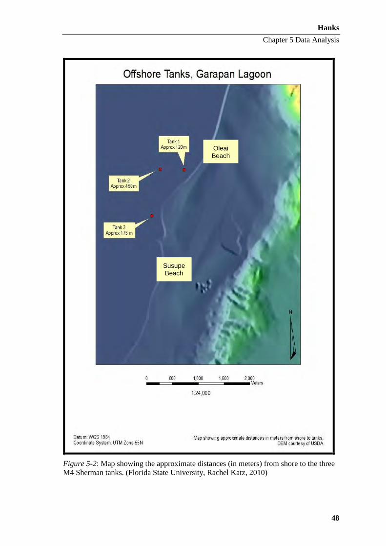
Hanks
Chapter 5 Data Analysis
48
Figure 5-2: Map showing the approximate distances (in meters) from shore to the three M4 Sherman tanks. (Florida State University, Rachel Katz, 2010)
Oleai Beach
Susupe Beach
Hanks
Chapter 5 Data Analysis
49
Flora and Fauna
Submerged portions of the tanks act as an artificial reef in the sand flats, hosting
mollusks, urchins, sponges, and small schools of juvenile fish. Coral are also beginning
to colonize on an around the tanks. A PhD student at the University of Technology in
Sydney conducted a biological survey and has provided a table of fish species
inhabiting each of the three Sherman tanks (Appendix II).
Environmental Conditions
The tanks are rarely completely inundated during high tides as the main gun
turrets remain above the waterline. It is worth noting, however, that the tidal nature of
the sites is not conducive to the formation of protective concretions. Rather, the
relatively high amount of water movement around the tanks will increase corrosion
potential and deterioration rates of the tanks due to increased dissolved oxygen in the
water. Dissolved oxygen concentrations are directly proportional to increased water
movement and inversely proportional to increased water depth; meaning, the higher the
dissolved oxygen content, the greater the corrosion rates and presence of marine life.
There are a number of factors linked to metal corrosion in a marine environment.
These include water pH, atmospheric and dissolved oxygen levels, temperature, water
movement, salinity, marine growth, and metal composition among others (North and
MacLeod 1986: 74-76). As a typical coastal environment, several of these attributes and
chemical properties can be expected to affect the three M4 tank sites. Firstly, they are
located in a tidal zone and are subject to a cyclic wetting and drying processes with
exposure to direct ultraviolet radiation. This places stress on the steel tank components,
resulting in active corrosion, flaking, and fractures. Second, seawater contains high
levels of chloride salts that accelerate the corrosion of ferrous metals. Furthermore, the
action of the tide and breaking waves increase the dissolved oxygen levels in the
seawater. In short, the dynamic nature of Saipan’s coastal environment is not conducive
to the preservation of the tanks.
Corrosion
All three Sherman tanks are moderately corroded below the waterline, while
rather uniform corrosion is apparent above the surface. This was identified on-site by

Hanks
Chapter 5 Data Analysis
50
the iron oxide’s bright red/orange coloration. The cyclical process of wetting and
drying, coupled with direct exposure to the sun, wind, and elements combine to form an
abrasive force that has unfavorable effects on cultural heritage. Other corrosive factors,
such as dissolved oxygen, water pH, and water movement, are higher in tidal areas like
those where the tanks are located (North and MacLeod 1986: 74-76). Human
disturbance is another contributor to accelerated deterioration and increase corrosion
potential. The data gathered for this thesis was selected to aid in the monitoring and
recording of the effects the environment and visitors may have on the tanks. Chapter Six
contains a more in depth description, specific location, and photographic record of
corrosion, damage, and missing components.
Tank 1
Description
Tank 1 is the northernmost site, located approximately 120 meters offshore. A
Garmin GPS 12XL (WGS 84) placed Tank 1 at 55P 0360758 1676687. This tank has
been identified as a M4A2 Dry model equipped with a 75mm gun (Figure 5-3). The
main cannon would have once been accompanied by one .50 caliber anti-aircraft gun
and two .30-06 caliber anti-personnel machineguns (Grove 1978: 133). However, these
auxiliary guns are no longer present (Figure 5-4). A serial number, “D50878,” was
located on the turret of Tank 1 (Figure 5-5). This alphanumeric sequence is indicative of
a turret variation known as “low bustle” (Laughlin 2010: 1). The front quadrant of the
D50878 turret was designed with a uniform 76.2mm thickness with the exception of the
right front where two incisions were made to clear the turret traversing gear. The
thickened turrets made their first appearance in April of 1943 and were in widespread
use by August of the same year (Laughlin 2010: 1).
M4A2 variants were equipped with twin General Motors 6-71 diesel engines and
a welded hull (Grove 1978: 131, Humble 1977: 91). The 6-71 designation indicates that
the engines were inline six cylinders, 71 series Detroit diesels. The hull of Tank 1 is
oriented with its bow toward the shore on a bearing of 133º. The main 75mm gun is
fixed on a bearing of 197º.

Hanks
Chapter 5 Data Analysis
51
Figure 5-3: The turret and main gun of Tank 1 protruding from the water. (Flinders University, photo by T. Massey, 2010)
Figure 5-4: The bow and forward hull of Tank 1. The tracks, front gunner’s port, and forward machine gun fixture are all visible. One meter scale. (Flinders University, photo by T. Massey, 2010)
Machine Gunner’s
Port
Driver’s Port
Forward Machine
Gun Fixture

Hanks
Chapter 5 Data Analysis
52
Figure 5-5: Serial number D50878 on the turret of Tank 1. Ten centimeter scale (Flinders University, photo by T. Massey, 2010)
Data Collected
The lower portion of the M4A2’s track and roller assembly is currently buried in
the sandy sediment (Figures 5-6 and 5-7). Water depth measurements taken around the
tank provide an idea of whether one portion of the tank sits lower than another (Table 5-
1). Depth measurements were taken around Tank 1 on 16 June 2010 between high and
low tide. On that day, high tide was 0.57 meters at 9:18 am and low tide registered at -
0.11 meters at 4:37 pm. Depths can also be applied to assess the proportion of the tank
that is subjected to wetting and drying with tidal fluctuations. A discussion on this data
will be presented later in this chapter.

Hanks
Chapter 5 Data Analysis
53
Figure 5-6. Plan view and starboard profile view of Tank 1. (Flinders University, site plan by M. Hanks, 2010)

Hanks
Chapter 5 Data Analysis
54
Figure 5-7: Photo of the buried track and roller assembly of Tank 1. 50 centimeter scale. (Flinders University, photo by T. Massey, 2010)
Table 5-1: Tank 1 water depth measurements in meters.
Area of Tank Depth (m)
Bow 1.35
Starboard bow 1.50
Starboard 1.70
Starboard stern 1.60
Stern 1.65
Port Stern 1.60
Port 1.41
Port bow 1.30
While investigating Tank 1, no swimmers or tour boats visited the site.
However, taking a break to eat lunch on the beach provided the perfect opportunity to
observe activities on and around the tank. Three swimmers used Tank 1 as a checkpoint
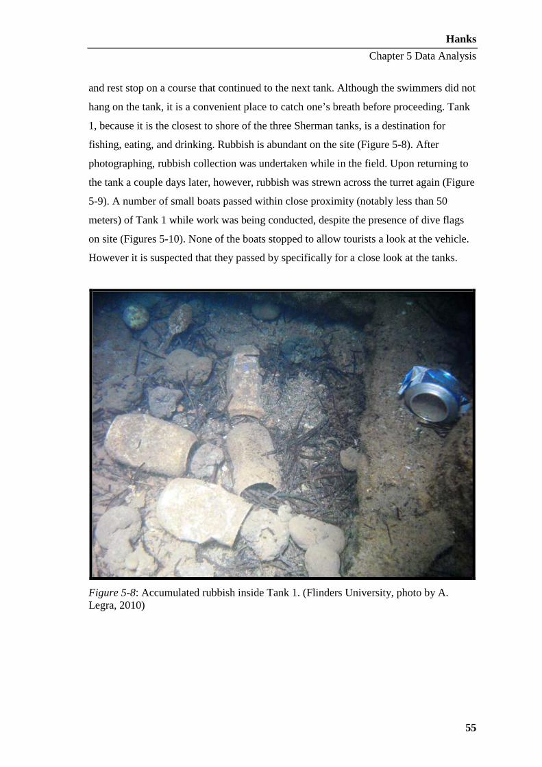
Hanks
Chapter 5 Data Analysis
55
and rest stop on a course that continued to the next tank. Although the swimmers did not
hang on the tank, it is a convenient place to catch one’s breath before proceeding. Tank
1, because it is the closest to shore of the three Sherman tanks, is a destination for
fishing, eating, and drinking. Rubbish is abundant on the site (Figure 5-8). After
photographing, rubbish collection was undertaken while in the field. Upon returning to
the tank a couple days later, however, rubbish was strewn across the turret again (Figure
5-9). A number of small boats passed within close proximity (notably less than 50
meters) of Tank 1 while work was being conducted, despite the presence of dive flags
on site (Figures 5-10). None of the boats stopped to allow tourists a look at the vehicle.
However it is suspected that they passed by specifically for a close look at the tanks.
Figure 5-8: Accumulated rubbish inside Tank 1. (Flinders University, photo by A. Legra, 2010)
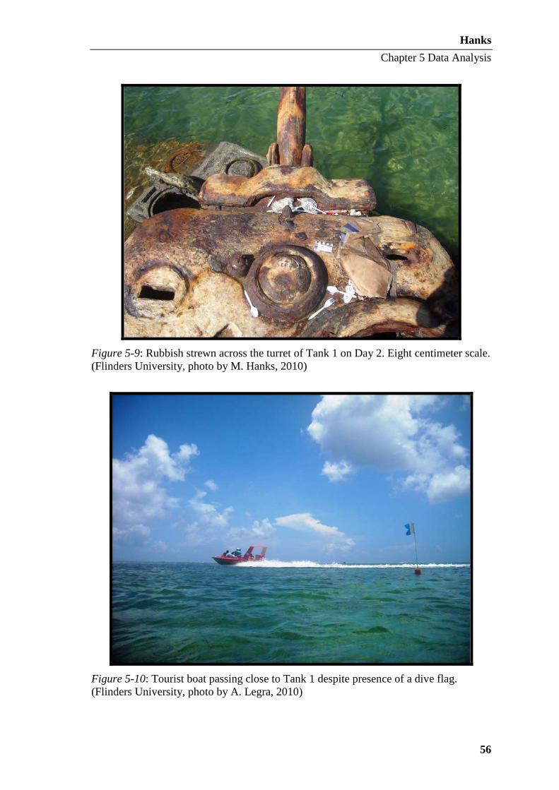
Hanks
Chapter 5 Data Analysis
56
Figure 5-9: Rubbish strewn across the turret of Tank 1 on Day 2. Eight centimeter scale. (Flinders University, photo by M. Hanks, 2010)
Figure 5-10: Tourist boat passing close to Tank 1 despite presence of a dive flag. (Flinders University, photo by A. Legra, 2010)

Hanks
Chapter 5 Data Analysis
57
The vegetation halos around the M4 Sherman tanks are an aspect that varied at
each tank site. Tank 1 had no vegetation directly adjacent to the vehicle, but was
surrounded by a ring of sand (Figure 5-11). Between 3.5 and 5.5 meters from the center
of the tank’s turret, seagrass appeared (Table 5-2).
Figure 5-11: Photo displaying the sand halo surrounding Tank 1. (Flinders University, photo by T. Massey, 2010)
Table 5-2: The distance and bearing of vegetation from the center of Tank 1.
Bearing Distance from center of Tank 1 to sand/vegetation interface (m)
5º 3.60
30º 3.80
70º 4.10
115º 4.30
135º 5.40
170º 5.50

Hanks
Chapter 5 Data Analysis
58
200º 5.50
220º 4.80
260º 4.40
305º 3.90
330º 3.70
Armored vehicles, such as tanks, are often on the frontlines in battle pushing
forward and therefore take the brunt of enemy firepower. Tanks’ armor, when it fulfils
its function, will deflect and absorb the impact of heavy fire. This action leaves its mark
on the vehicles. Battle scars and corrosion are evidence of the conflict these three M4
tanks have endured over the years. When combined, Saipan’s environment and the
tanks’ hulk react, taking a toll on these cultural heritage resources in the form of holes,
cracks, and corrosion (Figure 5-13).
Certain components of the tanks have disappeared altogether, while others are in
danger of being lost. Natural processes such as corrosion as well as cultural impacts like
salvage are the primary explanations for many missing components. This is particularly
true of long, thin parts of the vehicles like the main gun barrel as well as movable parts
such as brackets and hatches (Figure 5-12 and 5-14). Towing hooks, headlamp guards,
chassis lift hooks, tools, sirens, and radio aerial antennas have been lost to salvage or
nature (Figure 5-15).
Tank 1 displays the undeniable signs of unabated corrosion above and below the
waterline. Corrosion, cracks, and metal flaking are responsible for the loss of a notable
portion of tank components. A photographic catalogue of vulnerable components has
been collected to create a record for future monitoring reference and will be submitted
to HPO. For a more in depth description, specific location, and photographic record of
corrosion, suspected battle scars, and missing components on the three M4 tanks refer to
Chapter Six.

Hanks
Chapter 5 Data Analysis
59
Figure 5-12: Corrosion on Tank 1 turret hatch and missing hatch. (Flinders University, photo by J. McKinnon, 2010)
Figure 5-13: Active corrosion and hole on the starboard side of Tank 1. (Flinders

Hanks
Chapter 5 Data Analysis
60
University, photo by T. Massey, 2010)
Figure 5-14: Corrosion on the upper hull, turret, and main 75mm gun of Tank 1. (Ships of Discovery, photo by D. Ulloa, 2010)

Hanks
Chapter 5 Data Analysis
61
Figure 5-15: The remainder of a turret lift hook on Tank 1. Eight centimeter scale. (Flinders University, photo by M. Hanks, 2010)
Tank 2
Description
Tank 2 is also a M4A2 Dry tank with a 75mm cannon. Therefore, it was also
equipped with twin General Motors 6-71 diesel engines. As is the case with Tank 1, the
fixtures are still present, but none of the auxiliary weapons remain. Tank 2 is located
nearly 300 meters south of Tank 1 and about 450 meters offshore. The same Garmin
GPS 12XL (WGS 84) placed Tank 2 at 55P 0360293 1676694. The welded hull of Tank
2 is oriented with its bow shoreward on a bearing of 145º (Figure 5-16). The main gun
is fixed on a bearing of 270º (Figure 5-17).

Hanks
Chapter 5 Data Analysis
62
Figure 5-16: Main drive sprocket, suspension bogies, and tracks of Tank 2. 50 centimeter scale. (Flinders University, photo by K. Gauvin, 2010)
Figure 5-17: Image of Tank 2 illustrating the orientation of the main 75mm gun in relation to the hull. The bow is in the foreground. (Flinders University, photo by K.
Main Drive Sprocket
Tracks
Bogie Suspension
Unit
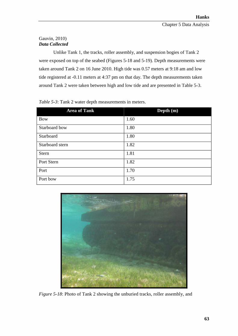
Hanks
Chapter 5 Data Analysis
63
Gauvin, 2010) Data Collected
Unlike Tank 1, the tracks, roller assembly, and suspension bogies of Tank 2
were exposed on top of the seabed (Figures 5-18 and 5-19). Depth measurements were
taken around Tank 2 on 16 June 2010. High tide was 0.57 meters at 9:18 am and low
tide registered at -0.11 meters at 4:37 pm on that day. The depth measurements taken
around Tank 2 were taken between high and low tide and are presented in Table 5-3.
Table 5-3: Tank 2 water depth measurements in meters.
Area of Tank Depth (m)
Bow 1.60
Starboard bow 1.80
Starboard 1.80
Starboard stern 1.82
Stern 1.81
Port Stern 1.82
Port 1.70
Port bow 1.75
Figure 5-18: Photo of Tank 2 showing the unburied tracks, roller assembly, and

Hanks
Chapter 5 Data Analysis
64
suspension bogies. (Flinders University, photo by K. Gauvin, 2010)
Figure 5-19. Plan view and starboard profile view of Tank 2. (Flinders University, site
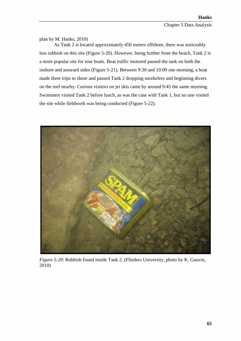
Hanks
Chapter 5 Data Analysis
65
plan by M. Hanks, 2010) As Tank 2 is located approximately 450 meters offshore, there was noticeably
less rubbish on this site (Figure 5-20). However, being further from the beach, Tank 2 is
a more popular site for tour boats. Boat traffic motored passed the tank on both the
inshore and seaward sides (Figure 5-21). Between 9:30 and 10:00 one morning, a boat
made three trips to shore and passed Tank 2 dropping snorkelers and beginning divers
on the reef nearby. Curious visitors on jet skis came by around 9:45 the same morning.
Swimmers visited Tank 2 before lunch, as was the case with Tank 1, but no one visited
the site while fieldwork was being conducted (Figure 5-22).
Figure 5-20: Rubbish found inside Tank 2. (Flinders University, photo by K. Gauvin, 2010)

Hanks
Chapter 5 Data Analysis
66
Figure 5-21: Tourist boat passing Tank 2 while pulling a “banana boat.” (Flinders University, photo by A. Legra, 2010)
Figure 5-22: Swimmers, in the background, on their way out to Tank 2. (Flinders University, photo by A. Legra, 2010)
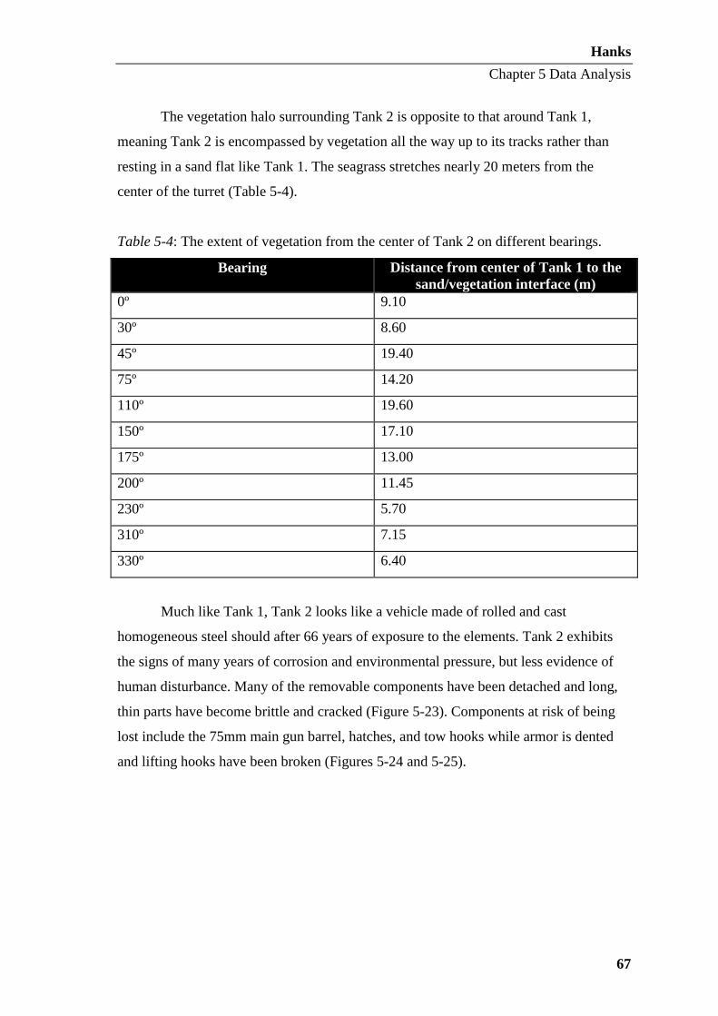
Hanks
Chapter 5 Data Analysis
67
The vegetation halo surrounding Tank 2 is opposite to that around Tank 1,
meaning Tank 2 is encompassed by vegetation all the way up to its tracks rather than
resting in a sand flat like Tank 1. The seagrass stretches nearly 20 meters from the
center of the turret (Table 5-4).
Table 5-4: The extent of vegetation from the center of Tank 2 on different bearings.
Bearing Distance from center of Tank 1 to the sand/vegetation interface (m)
0º 9.10
30º 8.60
45º 19.40
75º 14.20
110º 19.60
150º 17.10
175º 13.00
200º 11.45
230º 5.70
310º 7.15
330º 6.40
Much like Tank 1, Tank 2 looks like a vehicle made of rolled and cast
homogeneous steel should after 66 years of exposure to the elements. Tank 2 exhibits
the signs of many years of corrosion and environmental pressure, but less evidence of
human disturbance. Many of the removable components have been detached and long,
thin parts have become brittle and cracked (Figure 5-23). Components at risk of being
lost include the 75mm main gun barrel, hatches, and tow hooks while armor is dented
and lifting hooks have been broken (Figures 5-24 and 5-25).
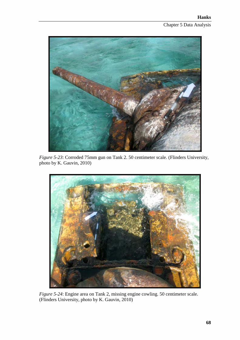
Hanks
Chapter 5 Data Analysis
68
Figure 5-23: Corroded 75mm gun on Tank 2. 50 centimeter scale. (Flinders University, photo by K. Gauvin, 2010)
Figure 5-24: Engine area on Tank 2, missing engine cowling. 50 centimeter scale. (Flinders University, photo by K. Gauvin, 2010)

Hanks
Chapter 5 Data Analysis
69
Figure 5-25: Corrosion on the turret hatch of Tank 2. 50 centimeter scale. (Flinders University, photo by K. Gauvin, 2010)
Tank 3
Description
Tank 3 is located approximately one kilometer south of Tank 2, about 175
meters offshore. The Garmin GPS 12XL placed Tank 3 at 55P 0360130 1675903 (WGS
84). This Sherman has been identified as a M4A3 Wet model equipped with a 75mm
gun. The auxiliary gun fixtures are intact, but the weapons are absent. M4A3s were
equipped with a Ford GAA V-8 gasoline engine and a welded hull (Grove 1978: 131,
Humble 1977: 91). Tank 3 differs from Tank 1 and Tank 2 not only in that it is an
M4A3 variant with wet ammunition stowage, but also its bow is pointing seaward on a
bearing of 295º (Figure 5-26). If this were in fact its original position, this orientation
would have put the Sherman in an extremely vulnerable position since the tank’s engine
fashioned in the stern. Any incoming enemy fire could strike the thinner rear armor and
potentially disable the engine. Several theories may be investigated as to why Tank 3 is
in this position. The first theory holds that the forward gear was damaged, crippling

Hanks
Chapter 5 Data Analysis
70
Tank 3, and the crew attempted to reverse to the beach. This hypothesis was unable to
be refuted or substantiated during June 2010 fieldwork. Another, more likely, theory
suggests that the tank crew became aware of a channel of deeper water between the
vehicle and shore, turned the M4A3 around and attempted to circumvent the deep water.
The wreckage of an U.S. landing craft lies between Tank 3 and the shore in deeper
water, its sinking may have alerted the tank crew to the obstacle. Lastly, Tank 3 may
have been moved, turned, or repositioned after the Battle during salvage activities.
The main gun is fixed on a bearing of 60º and the barrel is broken (Figure 5-27).
This break is thought to be the result of visitors hanging on and jumping off the 75mm
barrel based on activities recorded during the archaeological survey.
Figure 5-26: View of the stern of Tank 3, which faces the shore. The tracks, hull, and engine cowling are visible. (Flinders University, photo by T. Massey, 2010)
Engine Cowling
Rear Hull Plate
Tracks
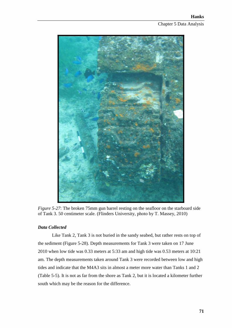
Hanks
Chapter 5 Data Analysis
71
Figure 5-27: The broken 75mm gun barrel resting on the seafloor on the starboard side of Tank 3. 50 centimeter scale. (Flinders University, photo by T. Massey, 2010)
Data Collected
Like Tank 2, Tank 3 is not buried in the sandy seabed, but rather rests on top of
the sediment (Figure 5-28). Depth measurements for Tank 3 were taken on 17 June
2010 when low tide was 0.33 meters at 5:33 am and high tide was 0.53 meters at 10:21
am. The depth measurements taken around Tank 3 were recorded between low and high
tides and indicate that the M4A3 sits in almost a meter more water than Tanks 1 and 2
(Table 5-5). It is not as far from the shore as Tank 2, but it is located a kilometer further
south which may be the reason for the difference.

Hanks
Chapter 5 Data Analysis
72
Figure 5-28. Plan view and starboard profile view of Tank 3. (Flinders University, site plan by M. Hanks, 2010)