hercules-c logo: hercules-c list of beneficiaries · figure 27: etb18 set-up at 2-stroke 4t50me-x...
TRANSCRIPT

HERCULES-C logo:
HERCULES-C List of Beneficiaries
No HERCULES-C BENEFICIARY (LEGAL NAME) SHORT NAME COUNTRY
1 National Technical University of Athens NTUA Greece
2 Aalto-Korkeakoulusaatio AALTO Finland
3 ABB Turbo Systems AG ABB Switzerland
4 Bodycote Metallurgical Coating Limited BODYCOTE United Kingdom
5 Chalmers Tekniska Hoegskola AB CHALMERS Sweden
6 Danfoss IXA AS DANFOSS Denmark
7 Danmarks Tekniske Universitet DTU Denmark
8 Eidgenössische Technische Hochschule Zürich ETH Zurich Switzerland
9 Federal-Mogul Burscheid GmbH FMO Germany
10 FEV GmbH FEV Germany
11 FOS Faseroptische Systeme Messtechnik GmbH FOS Germany
12 Gehring Technologies GmbH GEHRING Germany
13 IFP Energies Nouvelles IFPEN France
14 M. Jurgensen GmbH & Co KG MJ Germany
15 Karlsruher Institut Fuer Technologie KIT Germany
16 Man Diesel & Turbo SE MDT Germany
17 Paul Scherrer Institut PSI Switzerland
18 Pbs Turbo S.R.O. Velka Bites PBST Czech Republic
19 Technische Universitaet Graz TUG Austria
20 Tehag Engineering AG TEHAG Switzerland
21 Wartsila Finland Oy WFI Finland
22 Winterthur Gas & Diesel AG WINGD Switzerland
23 Flame Spray Technologies Ltd EPC United Kingdom

Figure 1: Projects in HERCULES Programme
2002
HERCULES-C17 M€ Budget
36 months duration
22 Partners
Vision R&D Project HERCULES ~80 M€ Budget, 10 years duration
2004 2005 2006 2007 2008 2009 2010 20112003
Phase III
I.P. HERCULES (A)33 M€ Budget
43 months duration
42 Partners HERCULES-B 26 M€ Budget
36 months duration
32 Partners
2012 2013 2014 2015
Phase II Phase I
Towards HERCULES-C
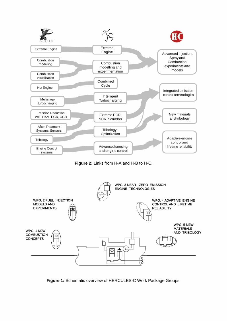
Figure 2: Links from H-A and H-B to H-C.
Figure 1: Schematic overview of HERCULES-C Work Package Groups.
Extreme Engine Extreme
Engine
Combustion
modelling Combustion
modelling and
experimentationCombustion
visualization
Hot Engine
Multistage
turbocharging
Emission Reduction:
WIF, HAM, EGR, CGR
After-Treatment
Systems, Sensors
Tribology
Engine Control
systems
Combined
Cycle
Intelligent
Turbocharging
Extreme EGR,
SCR, Scrubber
Tribology -
Optimization
Advanced sensing
and engine control
Advanced Injection,
Spray and
Combustion
experiments and
models
Integrated emission
control technologies
New materials
and tribology
Adaptive engine
control and
lifetime reliability
WPG. 1 NEW
COMBUSTION
CONCEPTS
WPG. 2 FUEL INJECTION
MODELS AND
EXPERIMENTS
WPG. 3 NEAR - ZERO EMISSION
ENGINE TECHNOLOGIES
WPG. 4 ADAPTIVE ENGINE
CONTROL AND LIFETIME
RELIABILITY
WPG. 5 NEW
MATERIALS
AND TRIBOLOGYWPG. 1 NEW
COMBUSTION
CONCEPTS
WPG. 2 FUEL INJECTION
MODELS AND
EXPERIMENTS
WPG. 3 NEAR - ZERO EMISSION
ENGINE TECHNOLOGIES
WPG. 4 ADAPTIVE ENGINE
CONTROL AND LIFETIME
RELIABILITY
WPG. 5 NEW
MATERIALS
AND TRIBOLOGY

Figure 4: HERCULES-C Work Packages and Participants.
WORK PACKAGE TITLE PARTICIPANTS LIST
WP 1: Advanced Combustion AALTO, WFI, WCH
WP 2: Computer Aided Combustion Optimization KIT, MDT, TUG
WP 3: Injection, Spray Formation and Combustion ETH Zurich, IFPEN, PSI, WFI, WCH
WP 4: Experimental and modeling studies of fuel injection systems CHALMERS, MDT
WP 5: Integrated emission control technologies ABB, PSI, WFI, WCH
WP 6: Near zero emission combustion and DPF technologies NTUA, DANFOSS, MDT, PBST, TEHAG
WP 7: Advanced system and plant control NTUA, AALTO, ETH Zurich, PSI, WFI
WP 8: Intelligent engine NTUA, FEV, MDT, TUG
WP 9: Cylinder lubrication concept for optimized emissions FOS, WCH
WP 10: Advanced bearing and combustion chamber technology EPC, DTU, FMO, GEHRING, MJ, MDT
WP 11 Administrative Management NTUA
WP 12 Technical Management NTUA, MDT, WFI, WCH
WP 13 Dissemination Activities NTUA, AALTO, CHALMERS, ETH Zurich, MDT, PSI, WFI
HERCULES-C WP’s and Participants
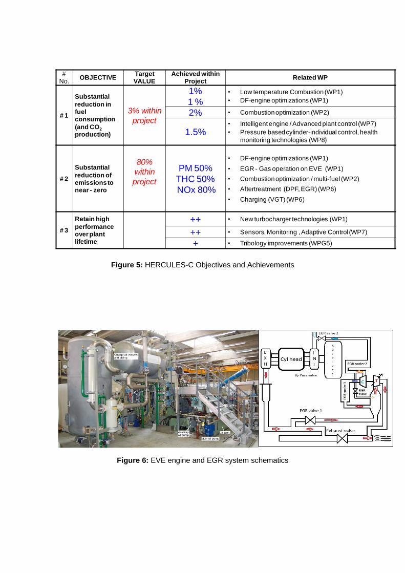
Figure 5: HERCULES-C Objectives and Achievements
Figure 6: EVE engine and EGR system schematics
# No.
OBJECTIVETarget VALUE
Achieved within Project
Related WP
# 1
Substantial
reduction in fuel consumption
(and CO2
production)
3% within
project
1%
1 %
• Low temperature Combustion (WP1)
• DF-engine optimizations (WP1)
2% • Combustion optimization (WP2)
1.5%• Intelligent engine / Advanced plant control (WP7)
• Pressure based cylinder-individual control, health
monitoring technologies (WP8)
# 2
Substantial
reduction of emissions to near - zero
80%
within
project
PM 50%
THC 50%
NOx 80%
• DF-engine optimizations (WP1)
• EGR - Gas operation on EVE (WP1)
• Combustion optimization / multi-fuel (WP2)
• Aftertreatment (DPF, EGR) (WP6)
• Charging (VGT) (WP6)
# 3
Retain high
performance over plant lifetime
++ • New turbocharger technologies (WP1)
++ • Sensors, Monitoring , Adaptive Control (WP7)
+ • Tribology improvements (WPG5)

Figure 7 – Difference in turbine efficiencies depending on optimisation
Figure 8: Nephelometer and FTIR emission measurement equipment
Figure 9: 2-stroke engine direct gas injection investigation test platforms; the hydraulic test rig and RT-
flex50D test engine.
Expansion ratio
Turb
ine
eff
icie
ncy
Turbine optimisedfor high loads
Turbine optimisedfor low loads

Figure 10: 4-stroke engine direct gas injection investigation test platform
Figure 11: Examples of optimization procedures for engine process (left) and combustion (right)
Figure 12: Engine improvement achieved by the onsite engine optimizer (two-stroke)

Figure 12: CFD of in-nozzle flow (left) and corresponding spray evolution measurements (right).
Figure 13: Spray Combustion Chamber test facility: application of Mie-scattering (left) for spray evolution and Phase Doppler Anemometry (PDA) to investigate LFO/HFO droplet size and velocity (right).
Figure 14: Ignition delay and location of LFO/HFO's by the application of advanced optical diagnostics
Droplet diameter histogram
Measurement volume
Nozzle tip
Configuration nr. 4
Exit velocity [m/s]
50
100
150
200
250
300
350
400Configuration nr. 2
Exit velocity [m/s]
50
100
150
200
250
300
350
400
CFD standard method
CFD tool incl. caviation
Reference nozzle
Eccentric nozzle

Figure 15: Combustion modeling; comparison different models (4-stroke, upper graph) and NOx distribution for different injection strategies (2-stroke, lower graph).
Figure 16: LES spray breakup simulation (fuel concentration, left) and 2-stroke engine process simulation (temperature distribution right) without/with consideration of nozzle eccentricity (left/right
image).
ECFM-3Z combustion ECFM-CLEH combustion DARS-TIF combustion
HFO, 1-component HFO, 3-component HFO, 5-component
Double-delay ignition Standard ignition TKI ignition
Ref. single injection
Multiple injection
ECFM-3Z combustion ECFM-CLEH combustion DARS-TIF combustion
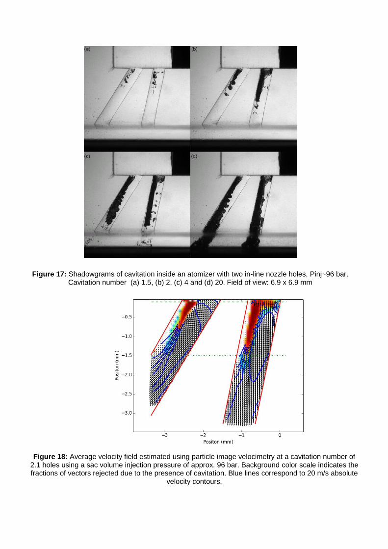
Figure 17: Shadowgrams of cavitation inside an atomizer with two in-line nozzle holes, Pinj~96 bar. Cavitation number (a) 1.5, (b) 2, (c) 4 and (d) 20. Field of view: 6.9 x 6.9 mm
Figure 18: Average velocity field estimated using particle image velocimetry at a cavitation number of 2.1 holes using a sac volume injection pressure of approx. 96 bar. Background color scale indicates the fractions of vectors rejected due to the presence of cavitation. Blue lines correspond to 20 m/s absolute
velocity contours.

Figure 19: SCR test hardware at Wärtsilä Finland laboratory. NOx reduction with two alternative urea injectors.
Figure 20: 2-stroke DF-engine with 2-stage turbocharging.
Figure 21: EGR test equipment at PSI. Correlation between EGR rate and NOx emission for semi-short route EGR system.

Figure 22: SCR combined with 2-stage turbocharging shown with both conventional valve system (right) and compact control valve (center). Control valve hardware (right).
Figure 23: Side view of developed SCR bench, showing inlet (1), heating and cooling (2) and flow producing fan (3).
Figure 24: 2-stage turbocharging and ETB12 set-up at 4-stroke test engine 6L32/44-CR (left) & NOx
reduction vs. blower speed at constant flap position (right)

Figure 25: Turbocharger of NTUA-LME research engine (left) & trajectory of measured data during
surge cycles (right)
Figure 26: PM emission and composition up- and down-stream of DPF (left) & transient (right) black
carbon emission up- (red) and down-stream (blue) of DPF
Figure 27: ETB18 set-up at 2-stroke 4T50ME-X test engine (left) & comparison of different WiF + EGR
setups (right)

Figure 28: Test of JiT-WiF basic concept at injection test rig (up left), EGR sensor installation (up
middle), block diagram (bottom)
Figure 29: Adaptive (MRAC) manifold air pressure control
Digital Signal Processing
and Interface
Danfoss IXA Sensor
Detector Output Signal
Pressure
Source Control
CO2Concentration
Source DetectorMeasurement Unit
Analog front-end
Droplet Filtering
EGR Receiver
H2OConcentration
PressureSensor
Ejector Pump
Gas Output

Figure 30: SCR (left) and hybrid engine system (right)
Figure 31: Test results with hybrid engine system

Figure 32: Results of engine test: Influence of adaptive combustion control (with Temperature after cylinder TCyl, mean effective pressure pmi and air fuel ratio -closed-loop) on engine performance
Figure 33: Image of the wear sensor head with overlaid sketch of major internal components
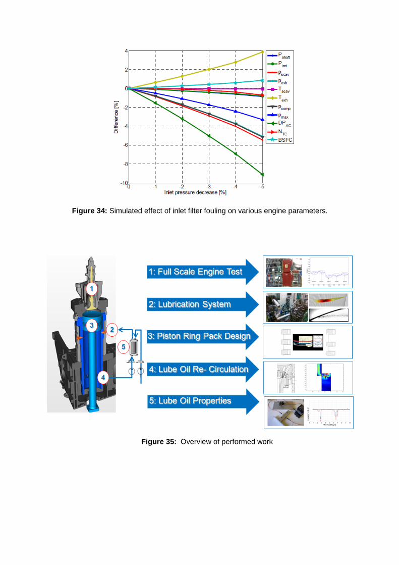
Figure 34: Simulated effect of inlet filter fouling on various engine parameters.
Figure 35: Overview of performed work

Figure 36: Lube oil evacuation groove performance simulation result
Figure 37: Performance evaluation of the new lubrication concept
Figure 38: Test rig for pre-validation of the selected combinations

Figure 39: Overview of averaged wear of piston ring and cylinder liner of reciprocating test rig
Figure 40: Result of the Particulate Matter measurements of new developed combinations of piston ring cylinder liner for 4-stroke
Figure 41: Influence on fuel consumption by the different tested versions
Series liner (reference) Liner … Liner … Liner … Pis
ton
rin
g w
ear
[µ
m]
A (ref.) B C D
Series liner (reference)
Liner PTWA Surface - A
Liner PTWA Surface - B
Liner GCI Surface - C
Lin
er
we
ar [
µm
]
A (ref.)
B
C
D
0%
200%
400%
600%
10% 25% 50% 75% 100%
PM
Em
issi
on
Engine Load
PM Emission of tested combinations
current Series
Target
Version A
Version B

Figure 42: Test of candidate no. 1 from the 2-stroke survey
Figure 43: Simulation and validation of cavitation in a lightly loaded journal bearing on the Cavitation Tets Rig (CTR)

Figure 44: Disc Fatigue Test Rig (DFTR) showing results of fatigue crack of a standard white metal compared to a simulation carried out utilizing TEHD
Figure 45: Application of Thermal Barrier Coating (TBC) on a cylinder cover for the T50ME-X research engine

Del. #
Deliverable Title
WP #
Delivery Date
(Month)
D2.1 Literature review of state-of-the-art in numerical optimisation
2 6
D13.1 Public section of Project Website complete and operational
13 6
D12.1 Progress Review of all Work Packages 12 12
D12.2 Interim presentation of overall project results 12 18
D13.2 Report on Dissemination Activities at Mid-Term 13 18
D12.3 Progress review and results update of all Work packages
12 24
D13.3 Compendium of scientific papers published by the Consortium
13 36
D13.5 Report on Dissemination Activities at End of Project
13 36
Figure 46: HERCULES-C Public Deliverables uploaded ion the Project web-site

Table of HERCULES-C Scientific Publications
No. Title
Authors
Date
Approved Conference / Journal
1 Influence of in-nozzle flow on spray morphology
Schmid, A., Habchi, C.,
Bohbot, J., Rotz, B.,
Herrmann, K., Bombach,
R., Weisser, G.
2/9/2014
ILASS - Europe 2014, 26th
Annual Conference on Liquid
Atomization and Spray
Systems, Bremen, September
2014,
2 Ignition behaviour of marine diesel fuels under
engine like conditions
Schmid, A., Rotz., B.,
Weisser, G., Herrmann, K. 2/9/2014
SAE 2014 International,
Birmingham, October 2014
3
Optimization of Tribodynamic Effects to improve
the Reduction Potential of Particulate Matter
Concentrations in the Exhaust Gas of Large Two
Stroke Marine Diesel Engines
Stark, M., Mittler, R. 1/9/2014 SAE 2014 International, USA,
October 2014
4
On the role of Cavitation in Marine Large Diesel
injector: Numerical investigation of nozzle
orifices eccentricity
Habchi, C., Gillet, N.,
Velghe, A., Bohbot, J.,
Schmid, A., Rotz, B.,
Hermmann, K.
1/9/2014
ILASS – Europe 26th Annual
Conference on Liquid
Atomization and Spray
Systems, September 2014,
Bremen
5 CMC model applied to marine diesel spray
combustion: Influence of fuel evaporation terms
Srna, A., Bolla, M.,
Boulouchos, K.,
Wright, Y.M.
1/9/2014 SAE 2014 International, USA,
October 2014
6 Methodology for Analysis and Simulation of Dual
Fuel Combustion in Large Engines
Krenn, M., Pirker, G.,
Wimmer, A., Djuranec, S.,
Meier, M., Wladenmaier,
U., Zhu, J.
18/8/2014
THIESEL 2014 Conference on
Thermo- and Fluid Dynamic
Processes in Direct Injection
Engines, Valencia, September
2014
7 Evaluation of PDA Applicability in Regard to
Heavy Fuel Oil Spray Investigations
Rotz, B., Kammermann,
T., Schneider, B., Schmid,
A., Herrmann, K., Weisser,
G., 8Boulouchos, K.
20/6/2014
17th International
Symposium on Applications
of Laser Techniques to Fluid
Mechanics, Lisbon, July 2014
8
Tribologische Optimierung von Großmotoren,
Geringere Emissionen und längere
Wartungsintervalle
Flores, G., Bugsch, M.,
Bastuck, T., Brauns, S. 19/6/2014
Symposium "Zylinderlaubahn,
Kolben, Pleuel", VDI-
Wissensforum, Baden-Baden,
June 2014.
9
HERCULES-1: The long term (2004-2014) R&D
programme on large engine technologies for
ships
Nikolaos P. Kyrtatos 16/5/2014 Transport Research Arena,
Paris, April 2014
10 Robust and Adaptive Wastegate Control of
Turbocharged Internal Combustion Engines Samokhin, S., Zenger, K. 4/2/2014
American Control
Conference, Portland, June
2014

Table of HERCULES-C Scientific Publications
11 Optical Diagnostics of Fuel Injection and Ignition
in a Marine Twostroke Diesel Engine
Hult, S., Matlok S., Mayer,
S. 6/2/2014
SAE World Congress 2014,
USA, April 2014
12
Influence of Injector Diameter (0.2-1.2 mm
range) on Diesel Spray Combustion:
Measurements and CFD Simulations
Bolla, Μ., Srna, Α., Wright,
Y. Rotz, B., Herrmann, K.,
Boulouchos, K.
11/2/2014 SAE World Congress 2014,
USA, April 2014
13 Modeling and Control of Diesel Engines with a
High-Pressure Exhaust Gas Recirculation System
Samokhin, S., Sarjovaara,
T., Zenger, K. 6/12/2013
IFAC World Congress 2014,
Cape Town, August 2014
14
Untersuchungen zur Strahlausbreitung und
Verbrennung unter typischen Bedingungen für
Grossdieselmotoren anhand eines speziell dafür
entwickelten Versuchsträgers
Weisser, G., Rotz, B.,
Schmid, A., Schulz,R.,
Herrmann, K.
19/9/2013
14. Tagung "der
arbeitsprozess des
verbrennungsmotors", Graz,
September 2013.
15 Influence of nozzle hole eccentricity on spray
morphology
Schmid, A., Rotz, B.,
Schulz,R., Herrmann, K.,
Weisser, G., Bombach, R.
18/9/2013
25th European Conference
on Liquid Atomization and
Spray Systems, Chania,
September 2013
16 Diesel Spray Breakup at Pressure
Falgout, Z., Rahm, M.,
Wang, Z., Sienes, E.,
Linne, M., Paciaroni, M.,
Hult, J., Matlok, S.
18/9/2013
25th European Conference
on Liquid Atomization and
Spray Systems, Chania,
September 2013
17 Testing of Bearing Materials for Large Two-
stroke Marine Diesel Engines
Klit, P., Persson, S.,
Voelund, A. 17/9/2013
12th EDF / Prime Workshop,
France, September 2014
18 Advanced optical development tools for two-
stroke marine diesel engines
Mayer, S., Hult, J.,
Nogenmyr, K., Clausen, S. 14/5/2013
27th CIMAC Congress,
Shanghai, May 2013
19 30 Mpa Mixing Controlled Combustion
Larmi, Μ., Kallio, I.,
Elonheimo, A., Sarjovaara,
T., Imperato, M.
13/5/2013 27th CIMAC Congress,
Shanghai, May 2013
20
Partially Premixed Combustion (PPC) for low
load conditions in marine engine using
computational and experimental techniques
Shrestha, K., Imperato,
M., Kaario, O., Larmi, M.,
Sarjovaara, T.
19/4/2013 Finnish – Swedish Flame
Days, Finland, April 2013
21
Optimization of Mixture Formation in Medium
Speed Dual-Fuel and Gas Engines with Support
of Advanced Optimization Techniques and
Optical Measurements
Waldenmaier, U.,
Djuranec, S., Stiesch, G.,
Unfug, F., Wagner, U.
19/3/2013 27th CIMAC Congress,
Shanghai, May 2013
22 Correlation of Internal Flow and Spray Breakup
for a Fuel Injector Used in Ship Engines
Linne, M., Falgout, Z.,
Rahm, M., Wang, Z.,
Paciaroni, M., Matlok, S.,
Hult, J.
19/3/2013 8th US National Combustion
Meeting, Utah, May 2013
23
Ten Years After: Results from the Major
Programme HERCULES A-B-C on Marine Engine
R&D
Kyrtatos, N., Hellberg, L.,
Poensgen, C. 27/2/2013
27th CIMAC Congress,
Shanghai, May 2013
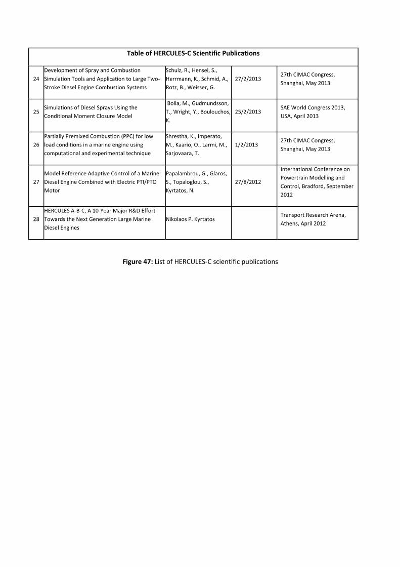
Table of HERCULES-C Scientific Publications
24
Development of Spray and Combustion
Simulation Tools and Application to Large Two-
Stroke Diesel Engine Combustion Systems
Schulz, R., Hensel, S.,
Herrmann, K., Schmid, A.,
Rotz, B., Weisser, G.
27/2/2013 27th CIMAC Congress,
Shanghai, May 2013
25 Simulations of Diesel Sprays Using the
Conditional Moment Closure Model
Bolla, M., Gudmundsson,
T., Wright, Y., Boulouchos,
K.
25/2/2013 SAE World Congress 2013,
USA, April 2013
26
Partially Premixed Combustion (PPC) for low
load conditions in a marine engine using
computational and experimental technique
Shrestha, K., Imperato,
M., Kaario, O., Larmi, M.,
Sarjovaara, T.
1/2/2013 27th CIMAC Congress,
Shanghai, May 2013
27
Model Reference Adaptive Control of a Marine
Diesel Engine Combined with Electric PTI/PTO
Motor
Papalambrou, G., Glaros,
S., Topaloglou, S.,
Kyrtatos, N.
27/8/2012
International Conference on
Powertrain Modelling and
Control, Bradford, September
2012
28
HERCULES A-B-C, A 10-Year Major R&D Effort
Towards the Next Generation Large Marine
Diesel Engines
Nikolaos P. Kyrtatos
Transport Research Arena,
Athens, April 2012
Figure 47: List of HERCULES-C scientific publications

Title Date Source
Land ahoy for cleaner, greener ship engines January 2014 Horizon 2020 Project Stories
Fathom Spotlight: All Hail Hercules! December
2013 Ship & Bunker
Results-driven Hercules research project in
third phase October 2013 The Motorship
Is Europe's mutli-forked fightback winning? May 2013 Lloyd's list
HERCULES-C June 2012 Naftiliaki – The Greek Shipping Review
Wärtsilä and MAN Diesel & Turbo to continue
comprehensive HERCULES Research Project May 2012 Marine-Diesels.net News
HERCULES-C May 2012 Transport Research & Innovation Portal
Productive outcome from Pan-European
engine research project April 2012 The Motorship
Herculean effort to raise emission standards March 2012 The Naval Architect
Hercules engines project enters next phase February 2012 Bairdmaritime.com
Hercules Project aims to develop zero-
emission engine February 2012 Lloyd’s list
Wärtsilä y MAN Diesel & Turbo avanzan en el
proyecto Hércules-C February 2012 Máquinas de Barcos
Next Phase Begins In Hercules Research
Program February 2012 Diesel & Gas Turbine Worldwide
Wärtsilä and MAN Diesel & Turbo enter... February 2012 Financial Express
Wärtsilä and MAN Diesel & Turbo enter Next
Phase of HERCULES Research Project February 2012 Marine Insight news
Wärtsilä, Man Diesel Continue Research February 2012 MarineLink.com
Wärtsilä and MAN Diesel & Turbo enter next
phase of HERCULES research project February 2012 Micportal
MAN Diesel & Turbo and Wärtsilä enter next
phase of HERCULES research project February 2012 Metal Supply
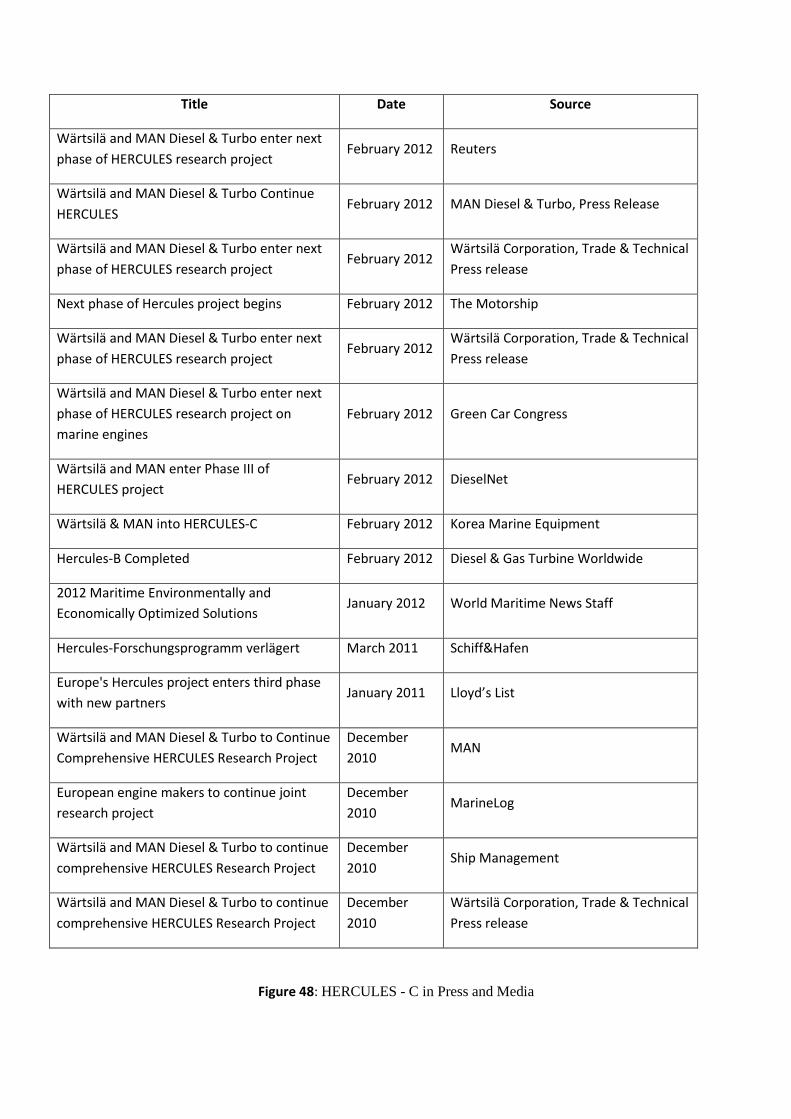
Title Date Source
Wärtsilä and MAN Diesel & Turbo enter next
phase of HERCULES research project February 2012 Reuters
Wärtsilä and MAN Diesel & Turbo Continue
HERCULES February 2012 MAN Diesel & Turbo, Press Release
Wärtsilä and MAN Diesel & Turbo enter next
phase of HERCULES research project February 2012
Wärtsilä Corporation, Trade & Technical
Press release
Next phase of Hercules project begins February 2012 The Motorship
Wärtsilä and MAN Diesel & Turbo enter next
phase of HERCULES research project February 2012
Wärtsilä Corporation, Trade & Technical
Press release
Wärtsilä and MAN Diesel & Turbo enter next
phase of HERCULES research project on
marine engines
February 2012 Green Car Congress
Wärtsilä and MAN enter Phase III of
HERCULES project February 2012 DieselNet
Wärtsilä & MAN into HERCULES-C February 2012 Korea Marine Equipment
Hercules-B Completed February 2012 Diesel & Gas Turbine Worldwide
2012 Maritime Environmentally and
Economically Optimized Solutions January 2012 World Maritime News Staff
Hercules-Forschungsprogramm verlӓgert March 2011 Schiff&Hafen
Europe's Hercules project enters third phase
with new partners January 2011 Lloyd’s List
Wärtsilä and MAN Diesel & Turbo to Continue
Comprehensive HERCULES Research Project
December
2010 MAN
European engine makers to continue joint
research project
December
2010 MarineLog
Wärtsilä and MAN Diesel & Turbo to continue
comprehensive HERCULES Research Project
December
2010 Ship Management
Wärtsilä and MAN Diesel & Turbo to continue
comprehensive HERCULES Research Project
December
2010
Wärtsilä Corporation, Trade & Technical
Press release
Figure 48: HERCULES - C in Press and Media

Figure 49: Table of HERCULES-C Exploitable results
Figure 50: EVE engine “cool combustion”
(TIMESPAN: SHORT=S, MEDIUM=M, LONG=L)
WORK PACKAGE GROUP ITEM TIME
WPG1
New Combustion Concepts
Advanced dual fuel gas engines with low temperature and partially premixed combustion and valving strategies for IMO Tier III
S
Combustion strategies compatible with aftertreatment methods (SCR, DPF)
M
WPG2
Fuel Injection Models & Experiments
Models for flow and cavitation applicable to large engine injectors
M
WPG3
Near–Zero Emission engine technologies
Combined SCR and Scrubber units S
Complete variability of turbocharging system combined with EGR equipment
M
Particulate Filters (DPF) and regeneration techniques for marine fuel including desulfurization & ash handling
M
Combined WIF (water-in-fuel) and EGR L
WPG4
Adaptive engine control & lifetime reliability
Combination of individual engine subsystem controllers to overall adaptive control
M
Self diagnostic algorithms and techniques for control system M
Sensors for wear detection integrated in health monitoring system
S
WPG5
New Materials & Tribology
Low friction and wear engine piston rings S
Increased performance main engine bearings M
Thermal Barrier Coatings for piston crowns M
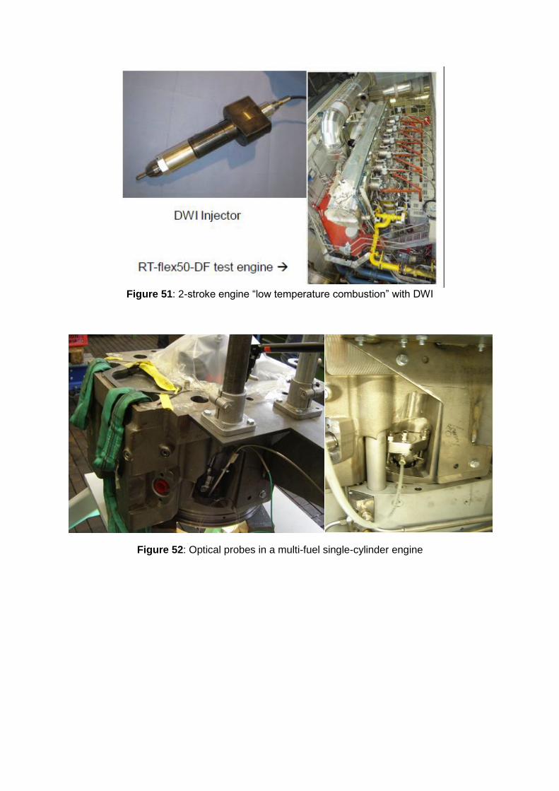
Figure 51: 2-stroke engine “low temperature combustion” with DWI
Figure 52: Optical probes in a multi-fuel single-cylinder engine
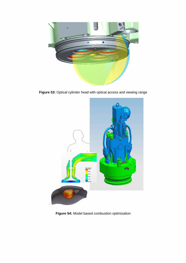
Figure 53: Optical cylinder head with optical access and viewing range
Figure 54: Model based combustion optimization
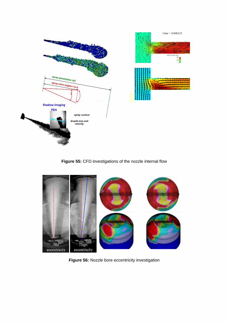
Figure 55: CFD investigations of the nozzle internal flow
Figure 56: Nozzle bore eccentricity investigation
STAR-CD vs. IFP-C3D (incl. cavitation model)
Reference case Eccentric nozzle case
IFP-C3D
StarCD
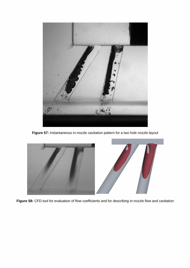
Figure 57: Instantaneous in-nozzle cavitation pattern for a two hole nozzle layout
Figure 58: CFD tool for evaluation of flow coefficients and for describing in-nozzle flow and cavitation

Figure 59: Sequential SCR concept with 2-stage turbocharging
Figure 60: DPF Substrate variant (left), coating performance (right)
Figure 61: DPF installation(left) and transient (right) black carbon emission up- (red) & down-stream
(blue) of DPF
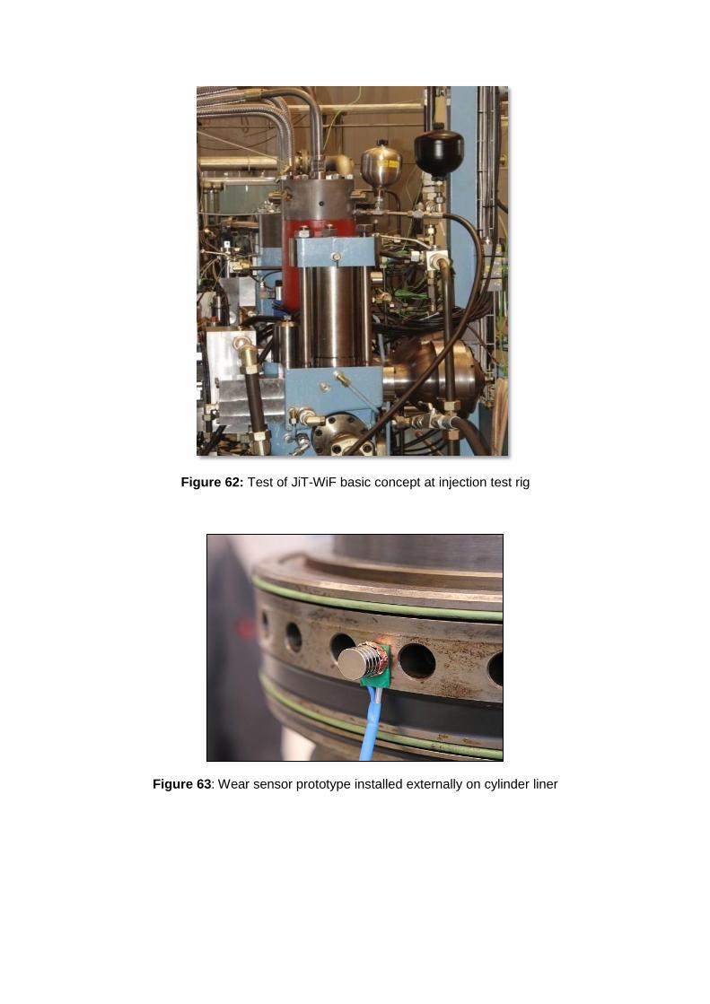
Figure 62: Test of JiT-WiF basic concept at injection test rig
Figure 63: Wear sensor prototype installed externally on cylinder liner

Figure64: Modified ring pack
Figure 65: New lube oil injectors
Figure 66: Lube oil re-circulation grooves

Figure 67: New Increased performance main engine bearings