heidari, hamidreza; rassõlkin, anton; holakooie, mohammad
TRANSCRIPT

This is an electronic reprint of the original article.This reprint may differ from the original in pagination and typographic detail.
Powered by TCPDF (www.tcpdf.org)
This material is protected by copyright and other intellectual property rights, and duplication or sale of all or part of any of the repository collections is not permitted, except that material may be duplicated by you for your research use or educational purposes in electronic or print form. You must obtain permission for any other use. Electronic or print copies may not be offered, whether for sale or otherwise to anyone who is not an authorised user.
Heidari, Hamidreza; Rassõlkin, Anton; Holakooie, Mohammad Hosein; Vaimann, Toomas;Kallaste, Ants; Belahcen, Anouar; Lukichev, Dmitry V.A parallel estimation system of stator resistance and rotor speed for active disturbancerejection control of six-phase induction motor
Published in:Energies
DOI:10.3390/en13051121
Published: 01/03/2020
Document VersionPublisher's PDF, also known as Version of record
Published under the following license:CC BY
Please cite the original version:Heidari, H., Rassõlkin, A., Holakooie, M. H., Vaimann, T., Kallaste, A., Belahcen, A., & Lukichev, D. V. (2020). Aparallel estimation system of stator resistance and rotor speed for active disturbance rejection control of six-phase induction motor. Energies, 13(5), [1121]. https://doi.org/10.3390/en13051121

energies
Article
A Parallel Estimation System of Stator Resistance andRotor Speed for Active Disturbance Rejection Controlof Six-Phase Induction Motor
Hamidreza Heidari 1,∗ , Anton Rassolkin 1 , Mohammad Hosein Holakooie 2 ,Toomas Vaimann 1 , Ants Kallaste 1 , Anouar Belahcen 1,3 and and Dmitry V. Lukichev 4
1 Department of Electrical Power Engineering and Mechatronics, Tallinn University of Technology,19086 Tallinn, Estonia; [email protected] (A.R.); [email protected] (T.V.);[email protected] (A.K.); [email protected] (A.B.)
2 Department of Electrical Engineering, University of Zanjan, Zanjan 45371-38791, Iran;[email protected]
3 Department of Electrical Engineering, Aalto University, 11000 Aalto, Finland4 Faculty of Control Systems and Robotics, ITMO University, 197101 St. Petersburg, Russia; [email protected]* Correspondence: [email protected]
Received: 03 February 2020; Accepted: 24 February 2020; Published: 2 March 2020
Abstract: In this paper, a parallel estimation system of the stator resistance and the rotor speed isproposed in speed sensorless six-phase induction motor (6PIM) drive. First, a full-order observer ispresented to provide the stator current and the rotor flux. Then, an adaptive control law is designedusing the Lyapunov stability theorem to estimate the rotor speed. In parallel, a stator resistanceidentification scheme is proposed using more degrees of freedom of the 6PIM, which is also basedon the Lyapunov stability theorem. The main advantage of the proposed method is that the statorresistance adaptation is completely decoupled from the rotor speed estimation algorithm. To increasethe robustness of the drive system against external disturbances, noises, and parameter uncertainties,an active disturbance rejection controller (ADRC) is introduced in direct torque control (DTC) of the6PIM. The experimental results clarify the effectiveness of the proposed approaches.
Keywords: active disturbance rejection controller (ADRC); direct torque control (DTC); full-orderobserver; sensorless; six-phase induction motor (6PIM); stator resistance estimator
1. Introduction
Three-phase induction motor drives have become a mature technology in the last years,but investigations into concepts of multiphase induction motor drives are still taking place. Multiphasedrive systems have a nearly 40-year history of research and study due to their promising advantagesagainst the conventional three-phase systems. The phase redundancy of the multiphase drives providesextra merits such as fault-tolerant operation, series-connected multimotor drive systems, asymmetryand braking systems. Six-phase induction motors (6PIMs) are known for its fault-tolerant capability, lowrate of inverter switches, and low DC-link voltage utilization compared with its three-phase one [1–3].On the other hand, the modular three-phase structure of the 6PIM allows the use of well-knownthree-phase technologies. The 6PIM is successfully used in special applications, such as electric ships,electric aircrafts, electric vehicles, and melt pumps, where the high reliability and continuity of theoperation are critical factors for the system [4]. The phase redundancy of the 6PIM provides the abilityof the open-phase fault-tolerant operation without any extra electronic components [5,6].
Among different structures of the 6PIM [4], the asymmetrical 6PIM with double isolated neutralpoints, which consists of two sets of three-phase windings spatially shifted by 30 electrical degrees,
Energies 2020, 13, 1121; doi:10.3390/en13051121 www.mdpi.com/journal/energies

Energies 2020, 13, 1121 2 of 17
has attracted the interest of many researchers [7–10]. The traditional three-phase control strategies,including switching table-based direct torque control (ST-DTC) [7], modulation-based DTC [8], thefield-oriented control (FOC) [9], and finite control set-model predictive control (FCS-MPC) [10], canbe extended to 6PIM (or other multi-phase machines) with some modifications to use more freedomdegrees that exist in multi-phase machines. DTC is a well-accepted technique due to its simplicity, quickdynamics, and robustness [11]. The modulation-based DTC strategy offers better phase current, torque,and flux response. On the contrary, this method has more complexity against conventional ST-DTC.The ST-DTC approach has straightforward and simple structure, but it is completely overshadowedby low-order harmonics due to unused voltage vectors in the losses subspaces. To overcome thisrestriction, the idea of duty cycle control is introduced by several researchers [12,13].
The rapid development of intelligent and high-performance control technologies has also broughtabout changes in the adjustable speed drive system for different industrial applications [14,15].To operate safely and reliably under different conditions, there is a lot of debate nowadays about themain control strategy of the system [16,17]. Among different high-performance control strategies ofdrive systems, the DTC strategy has a straightforward algorithm. The DTC technique is inherentlyspeed sensorless. Nevertheless, if an outer speed loop is added to the DTC, the speed value isalso necessary. Sensorless three/multi-phase induction machine drives are widely addressed inthe technical literature due to multiple shortcomings of shaft encoders [18–23]. To investigate theinstability problem of the traditional rotor flux-based model reference adaptive system (MRAS)speed estimators in the regenerating-mode low-speed operation, a stator current-based and backelectromotive force-based MRASs are addressed in [19,20], respectively. In [21], two modifiedadaptation mechanisms are proposed to replace the classical proportional-integral (PI) regulator. Thefull-order Luenberger and Kalman filter observers are discussed in [22,23], respectively. Providing aDTC drive system with parallel identification of the rotor speed and the stator resistance is a challengingtask because the operation of the DTC scheme is severely dependent on the stator resistance. Thisproblem is sporadically reported for three-phase induction machines (3PIMs) [24,25], where the rotorspeed and the stator resistance estimators encounter an overlap due to limited freedom degrees of3PIM. In this paper, the problem of parallel estimation is investigated using more freedom degreesof 6PIM.
The outer speed control loop of the DTC scheme conventionally contains the PI regulator to obtaintorque command from speed error. In general, the control law of a PID regulator is a linear combinationof proportional-integral-derivative terms, which is suitable for linear systems. For nonlinear systems,such as the 6PIM drive system, the PI regulator has been given a lot of attention due to its simplicity.However, it suffers from multiple problems including: (1) tuning of its parameters; (2) high sensitivityagainst noise and external disturbances; and (3) loss of efficiency due to oversimplified controllaw [26,27]. One promising technique to relatively get rid of the drawbacks of PI regulator is activedisturbance rejection controller (ADRC) [26,28]. The ADRC is a nonlinear control scheme, whichprovides a robust control against noises, external disturbances, and parameter uncertainties. For thesereasons, the ADRC technique has recently attracted more attention for electric drive systems. To addressthis issue, a modified FOC scheme based on first-order ADRCs for current and speed control loops isproposed in [29]. A combined active disturbance rejection and sliding-mode controller for an inductionmotor is presented to achieve total robustness [30].
The aim of this paper is to present an ADRC-based DTC scheme for sensorless 6PIM drives.The speed estimator is based on adaptive full-order observer, and its control law is designed usingLyapunov stability theorem. Besides the speed estimation system, a stator resistance estimator isproposed using additional degrees of freedom of the 6PIM to enhance the robustness of the sensorlessDTC strategy against stator resistance uncertainties. The adaptation law for the stator resistanceestimator is derived using the Lyapunov stability theorem to ensure its overall convergence.
The rest of this paper is organized as follows. Section 2 introduces the mathematical model of the6PIM. Section 3 presents the design procedure of the adaptive full-order observer, the speed estimator,

Energies 2020, 13, 1121 3 of 17
and the stator resistance estimator. The DTC scheme of the 6PIM is discussed in Section 4, whichincludes the ST-DTC scheme, and ADRC in DTC. The experimental results are presented in Section 5.Finally, Section 6 summarizes the findings and concludes the paper.
2. Dynamic Model of 6PIM
There are two popular approaches for modeling of the multi-phase machines: (1) multiple d–qapproach [9]; (2) vector space decomposition (VSD) approach [31]. The first method is exclusively usedfor modular three-phase structures-based multi-phase machines such as six-phase and nine-phasemachines. However, the second method can be used for all types of multi-phase machines. In thisresearch, the VSD approach is used, where a 6PIM with distributed windings is modeled in the threeorthogonal subspaces, i.e., the α− β, z1 − z2 and o1 − o2. Among them, only the α− β variables are inrelation with electromechanical energy conversion, while z1 − z2 and o1 − o2 variables do not activelycontribute to the torque production.
The schematic diagram of a six-phase voltage source inverter (VSI)-fed an 6PIM with two isolatedneutral points is shown in Figure 1. The transfer between the normal a− x− b− y− c− z variablesand α− β− z1 − z2 − o1 − o2 variables is performed by T6 transformation matrix as follows [31]:
T6 =13
1√
32 − 1
2 −√
32 − 1
2 0
0 12
√3
212 −
√3
2 −1
1 −√
32 − 1
2
√3
2 − 12 0
0 12 −
√3
212
√3
2 −1
1 0 1 0 1 00 1 0 1 0 1
(1)
By applying T6 matrix to the voltage equations in the original six-dimensional system, the 6PIMmodel can be represented in the three orthogonal submodels, identified as α− β, z1 − z2, and o1 − o2.The voltage space vector equations of the 6PIM in the α− β subspace are written as follows:
vs = Rsis + pΨs (2)
0 = Rrir + pΨr − jωrΨr (3)
The flux linkages areΨs = Lsis + Lmir (4)
Ψr = Lmis + Lrir (5)
where v, i, Ψ, R, and L represent voltage, current, flux linkage, resistance, and inductance,respectively, for stator (s subscript) and rotor (r subscript) quantities, and p denotes derivative operator.The electromagnetic torque produced by the 6PIM is expressed as
Te = 3PΨs ⊗ is (6)
where P is pole pairs and ⊗ denotes the cross product.The 6PIM voltage equations in the z1 − z2 subspace are the same as a passive R-L circuit as follows:
vsz1 = Rsisz1 + Lls pisz1 (7)
vsz2 = Rsisz2 + Lls pisz2 (8)
where Lls is stator leakage inductance.On the presumption that the stator mutual leakage inductances can be neglected, the 6PIM model
in the o1 − o2 subspace has the same form of the z1 − z2 subspace. However, the applied 6PIM with

Energies 2020, 13, 1121 4 of 17
two isolated neutral points avoids zero-sequence currents because it contains two sets of balancedthree-phase windings.
+
_
6PIM
C
E
G
C
E
G
a x b y c z
as
xs
bsys
cszs
11s
12s
13s
14s
15s
16s
21s
22s
23s
24s
25s
26s
30
vdc
Figure 1. Six-phase two-level VSI-fed 6PIM.
3. Adaptive Full-Order Observer
The block diagram of the proposed Rs and ωr estimators based on the adaptive state observer isshown in Figure 2. It contains the stator current and rotor flux observers, the stator resistance identifier,and the rotor speed estimator, which are discussed below.
Speed
adaptation
law
6PIM
(Reference model)
sV
s
i
Stator
resistance
adaptation
law
ˆr
State observer
Z1-Z2 subspace
ˆs
R
ˆr
ˆs
R ˆr
1 2sz zi
1 2
ˆsz z
i
1 2sz zV
1 2sz zi
1 2
ˆsz z
i
State observer
alpha-beta subspace
Figure 2. The block diagram of the proposed parallel estimation system of the stator resistance and therotor speed based on an adaptive full-order observer.
3.1. Stator Current and Rotor Flux Observers
The general form of state-space model of the 6PIM in the α− β subspace isx1 = A1x1 + B1u1
y1 = C1x + D1u1(9)

Energies 2020, 13, 1121 5 of 17
Assuming stator current and rotor flux as state variables and using Equations (2) and (3), the elementsof state-space representation in α− β subspace will be
x1 =[isα isβ ψrα ψrβ
]T(10)
A1 =
[(− Rs
σLs− 1−σ
σTr)I Lm
σLs Lr( 1
TrI −ωr J)
LmTr
I − 1Tr
I + ωr J
](11)
B1 =[
1σLs
I O]T
(12)
u1 =[vsα vsβ
]T(13)
y1 =[isα isβ
]T(14)
C1 =[
I O]
(15)
with
I =
[1 00 1
], J =
[0 −11 0
], O =
[0 00 0
](16)
where Tr = Lr/Rr is rotor time constant and σ = 1− L2m/LsLr is leakage coefficient.
The state observer of the 6PIM has a similar form of state-space representation except that anadditional compensation term based on error of measurable states and observer gain matrix is addedto it. The state observer can be written as
˙x1 = A1 x1 + B1u1 + G1(is − is)
y1 = C1 x1(17)
where the marker ∧ indicates the estimated values, and G1 is the observer gain matrix. The matrix A1
contains unknown parameters of the 6PIM such as the rotor speed and the stator resistance. Theseparameters can be estimated by the designing of a suitable adaptation control law with a nonlineartheorem such as a Lyapunov stability theorem. It is worth mentioning here that the matrix A1 alsocontains the rotor time constant. However, simultaneous estimation of the rotor speed, the rotortime constant, and the stator resistance is challenging because of persistency of excitation conditionsproblem [32]. Some techniques have recently been developed based on signal injection to providepersistent excitation [33], which suffer from steady-state torque and speed ripples. In this paper, thestator resistance is estimated from additional degrees of freedom of the 6PIM, while the rotor speed isprovided using the 6PIM equations in α− β subspace. This procedure provides the stator resistanceindependent from the rotor speed.
The observer gain matrix G1 must be designed to ensure stability and good dynamic response ofthe observer at a wide range of the speeds. Using pole-placement method, the elements of matrix G1 isprovided as [22,34]
G1 =
[g1 g2 g3 g4
−g2 g1 −g4 g3
]T
(18)
where g1 = (1− Kpo)(RsL2
r + RrL2m)/σLsL2
r
g2 = (Kpo − 1)ωr
g3 = (Kpo − 1)(RsLs − KpoRsLr)/Lm
g4 = (1− Kpo)ωrσLsLr/Lm
(19)

Energies 2020, 13, 1121 6 of 17
where Kpo > 0 is observer constant gain.
3.2. Stator Resistance Identification
In this paper, a stator resistance adaptation system is proposed using the machine model in thez1− z2 subspace. This method can be utilized for any multi-phase machines. It is completely decoupledfrom the rotor speed and the rotor time constant, whereas most of the conventional stator resistanceestimators, developed for three-phase machines, are related to these parameters. The proposed Rs
estimator only depends on the stator leakage inductance Lls, which can be approximately assumed tobe constant.
The state-space model of 6PIM in the z1 − z2 subspace, with consideration of isz1 and isz2 as thestate variables, can be derived from Equations (7) and (8) as follows:[
isz1
isz2
]=
[− Rs
Lls0
0 − RsLls
] [isz1
isz2
]+
1Lls
[vsz1
vsz2
][
isz1
isz2
]=
[1 00 1
] [isz1
isz2
](20)
In this case, the proposed states observer is given by˙x2 = A2 x2 + B2u2
y2 = C2 x2(21)
It should be noted that a correction term G2(x2 − x2) is neglected in Equation (21) due to the inherentstability of the observer.
The proposed adaptation law for the stator resistance estimation is
Rs = KprεRS + Kir
∫εRS dt (22)
where Kir and Kpr are the integral and proportional gains, respectively, and εRS is the stator resistanceerror signal
εRS = isz1(isz1 − isz1) + isz2(isz2 − isz2) (23)
The proof for the stator resistance adaptation law is presented in Appendix A.
3.3. Rotor Speed Estimation
In order to design the speed adaptation law, it is considered as an unknown parameter. First,an appropriate positive definite function is chosen as the Lyapunov candidate. Then, the adaptationlaw is obtained using the Lyapunov criterion to ensure asymptotic stability of the system. The speedadaptation law is
ωr = Kpωεω + Kiω
∫εωdt (24)
where Kpω and Kiω are proportional and integral gains, respectively, and εω is the speed error signalas follows:
εω = (isα − isα)ψrβ − (isβ − isβ)ψrα (25)
The proof for the speed adaptation law is presented in Appendix B.

Energies 2020, 13, 1121 7 of 17
4. DTC of 6PIM
4.1. ST-DTC Scheme
A six-phase VSI contains overall 26 = 64 different voltage space vectors, 60 active, and four zerovectors, where the active voltage vectors are distributed in four non-zero levels depicted in Figure 3.The electrical angle of each sectors is 30. The 6PIM phase-to-neutral voltages can be calculated as
Va
VbVc
Vx
Vy
Vz
=
Vdc3
2 −1 −1 0 0 0−1 2 −1 0 0 0−1 −1 2 0 0 00 0 0 2 −1 −10 0 0 −1 2 −10 0 0 −1 −1 2
Sa
SbSc
Sx
Sy
Sz
(26)
where Si = 0, 1, i = a, x, b, y, c, z is the switching state. When Si = 1 (Si = 0), the correspondingstator terminal is connected to positive (negative) DC-link rail. The voltage space vectors are given by
vs =13[Va + aVx + a4Vb + a5Vy + a8Vc + a9Vz] (27)
vz =13[Va + a5Vx + a8Vb + aVy + a4Vc + a9Vz] (28)
where vz = vsz1 + jvsz2 and a = ejπ/6.The flux estimator is obtained from
ψsα =∫(vsα − Rsisα)dt (29)
ψsβ =∫(vsβ − Rsisβ)dt (30)
and the toque estimator is obtained from (6). In the traditional ST-DTC, the torque and stator flux errorsare applied to hysteresis regulators to provide the sign of torque (εT) and stator flux (εψ). Accordingto gained signals and also the position of stator flux, a proper large voltage vector is selected based onTable 1 during each sampling period. From Figure 3, the corresponding voltage vectors in the z1 − z2
subspace will produce large current harmonics, when only large voltage vectors are used to controlthe torque and flux. Hence, it can alleviate the current harmonics through reduction of the z1 − z2
components by applying a combined voltage vector during each sampling period. This technique isreferred to as duty cycle control, where a virtual vector (synthesized by large and medium voltagespace vectors) is applied to the inverter in each sampling period because the large and medium voltagevectors are in the opposite direction in the z1 − z2 subspace (see Figure 3). The duration of the appliedvectors is calculated in order to reduce the average volt-seconds in the z1 − z2 subspace [4]. The blockdiagram of the proposed sensorless DTC strategy with the adaptive full-order observer is shown inFigure 4a. In this figure, the speed control loop is based on the ADRC strategy, which will be discussedin the next subsection.

Energies 2020, 13, 1121 8 of 17
Figure 3. The α− β (top side) and the z1 − z2 (down side) vector subspaces for a six-phase VSI.
Table 1. Switching table of DTC strategy.
εT εψ Selected Voltage *
1 1 Vm+11 0 Vm+40 1 V00 0 V0−1 1 Vm−2−1 0 Vm−5
* m is sector number.
Duty
Cycle
6PIM
Voltage
Source
Inverter
Adaptive
Full-order
observer
Sector
Determination
Hysteresis
Regulator
ADRC
Modified
Switching
Table
Saxbycz
Vdc
3
3
iabc
ixyz
T
*s
*eT
*r_
+
+
_
Hysteresis
Regulator+
_
ˆ s
ˆ sˆeT
ˆ r
(a)
Figure 4. Cont.

Energies 2020, 13, 1121 9 of 17
Extended state
observer
Plant Nonlinear
differentiator
Nonlinear
control law
b01/b0
Disturbances
+_ _
+
1z
2z
1e yu0
uv 1v
(b)
Figure 4. Block diagram of (a) the proposed sensorless DTC strategy; (b) ADRC.
4.2. ADRC in DTC
To enhance the robustness of the DTC technique against external disturbances and measurementnoises, the ADRC is proposed to replace with the conventional PI regulator in the outer speed controlloop. The block diagram of ADRC is shown in Figure 4b. It consists of three main elements: (1) nonlineardifferentiator; (2) extended state observer; (3) nonlinear control law.
In some industrial applications, the command values are changed as step function, which is notsuitable for the control system because of a sudden jump of output and control signals. To solvethis problem, the nonlinear differentiator is used, which makes a reasonable transient profile fromcommand signals for tracking [26]. The nonlinear differentiator can be expressed by
v1(k + 1) = v1(k) + hv2(k)
v2(k + 1) = v2(k) + h f1(v1(k)− v(k), v2(k), r0, h0)(31)
where f1 is a nonlinear function as
f1(v1(k), v2(k), r0, h0) = −
a(k)/h0 |a(k)| ≤ r0h0
r0sign(a(k)) |a(k)| > r0h0(32)
with
a(k) =
v2(k) + y0(k)/h0 |a(k)| ≤ r0h2
0
v2(k) + (a0(k)− r0h0)/2 |a(k)| > r0h20
y0(k) = v1(k) + h0v2(k)
a0(k) =√(r0h0)2 + 8r0|y0(k)|
where r0 and h0 are the parameters of the nonlinear differentiator, and h is sampling period.The extended state observer is an enhanced version of feedback linearization method to
compensate the total disturbances of the system. Using this observer, the state feedback term can beestimated online; hence, it is an adaptive robust observer against model uncertainties and externaldisturbances. The extended state observer is represented as follows:
z1(k + 1) = z1(k) + h[z2(k)− β1 f2(e(k), α1, δ1) + b0u(k)]
z2(k + 1) = z2(k)− hβ2 f2(e(k), α1, δ1)
e(k) = z1(k)− y(k)
(33)
where the nonlinear function f2 is defined as
f2(e(k), α, δ) =
e(k)/δ1−α |e(k)| ≤ δ
|e(k)|αsign(e(k)) |e(k)| > δ(34)
where α1, δ1, β1, β2, and b0 are the parameters of the extended state observer.

Energies 2020, 13, 1121 10 of 17
The conventional PI controller is based on the linear combination of proportional and integral termsof error, which may degrade the performance of the DTC scheme. Different nonlinear combination oferror can be presented to overcome this problem. In this paper, the following nonlinear control lawis used:
e1(k) = v1(k)− z1(k)
u0(k) = β3 f2(e1(k), α2, δ2)
u(k) = u0(k)− z2(k)/b0
(35)
where α2, β3, and δ2 are the parameters of nonlinear control law.
5. Experimental Validation
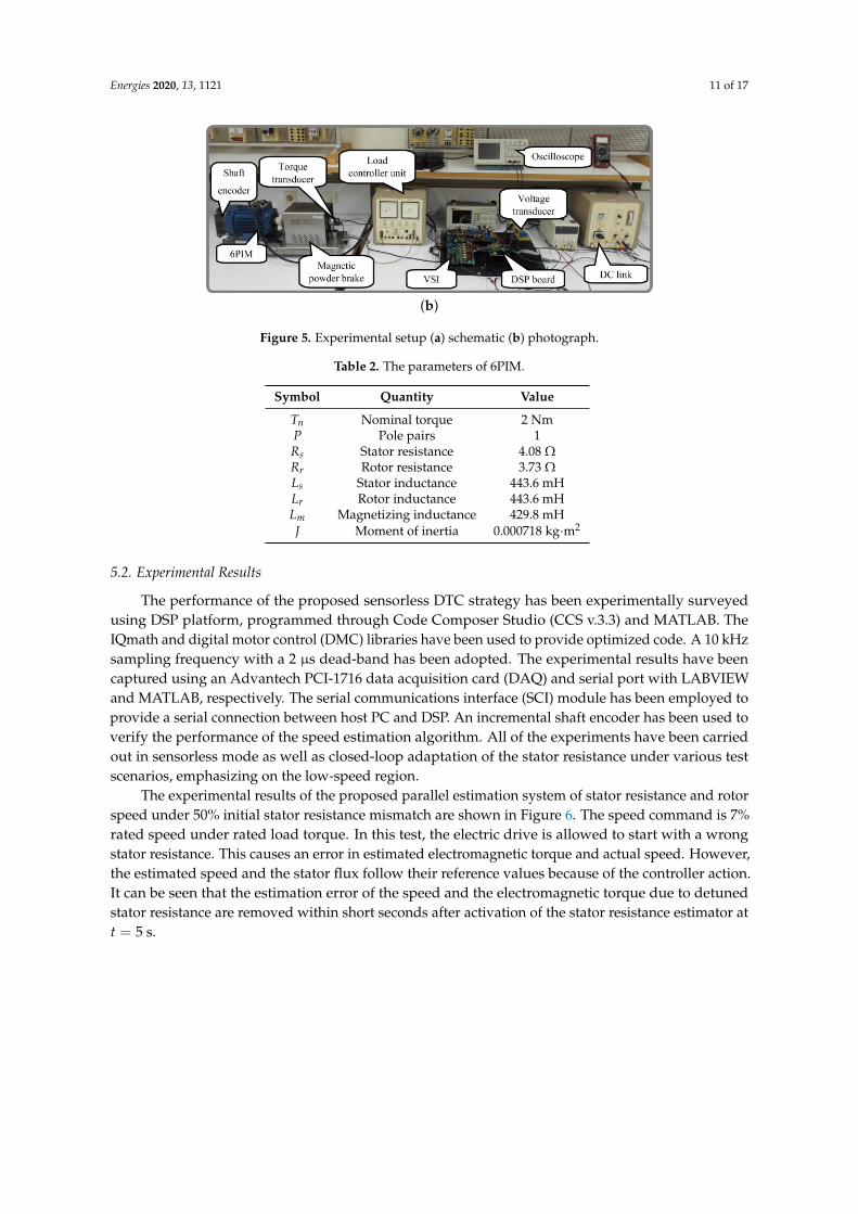
5.1. Description of Experimental Setup
The schematic and photograph of the experimental setup are shown in Figure 5a,b, respectively.The principal elements are
• a TMS320F28335-based digital signal processor (DSP) board.• two custom-made two-level three-phase VSIs based on BUP 314D IGBTs and LEM LTS 6-NP
current transducers.• an LEM LV25-P voltage transducer.• an Autonics incremental shaft encoder.• a magnetic powder brake mechanically coupled to the 6PIM.• a bridge rectifier.• a 1-hp three-phase induction motor, which has been rewound to provide an asymmetrical 6PIM.
The specifications of the 6PIM are shown in Table 2.
(a)
Figure 5. Cont.
Energies 2020, 13, 1121 11 of 17
(b)
Figure 5. Experimental setup (a) schematic (b) photograph.
Table 2. The parameters of 6PIM.
Symbol Quantity Value
Tn Nominal torque 2 NmP Pole pairs 1Rs Stator resistance 4.08 ΩRr Rotor resistance 3.73 ΩLs Stator inductance 443.6 mHLr Rotor inductance 443.6 mHLm Magnetizing inductance 429.8 mHJ Moment of inertia 0.000718 kg·m2
5.2. Experimental Results
The performance of the proposed sensorless DTC strategy has been experimentally surveyedusing DSP platform, programmed through Code Composer Studio (CCS v.3.3) and MATLAB. TheIQmath and digital motor control (DMC) libraries have been used to provide optimized code. A 10 kHzsampling frequency with a 2 µs dead-band has been adopted. The experimental results have beencaptured using an Advantech PCI-1716 data acquisition card (DAQ) and serial port with LABVIEWand MATLAB, respectively. The serial communications interface (SCI) module has been employed toprovide a serial connection between host PC and DSP. An incremental shaft encoder has been used toverify the performance of the speed estimation algorithm. All of the experiments have been carriedout in sensorless mode as well as closed-loop adaptation of the stator resistance under various testscenarios, emphasizing on the low-speed region.
The experimental results of the proposed parallel estimation system of stator resistance and rotorspeed under 50% initial stator resistance mismatch are shown in Figure 6. The speed command is 7%rated speed under rated load torque. In this test, the electric drive is allowed to start with a wrongstator resistance. This causes an error in estimated electromagnetic torque and actual speed. However,the estimated speed and the stator flux follow their reference values because of the controller action.It can be seen that the estimation error of the speed and the electromagnetic torque due to detunedstator resistance are removed within short seconds after activation of the stator resistance estimator att = 5 s.

Energies 2020, 13, 1121 12 of 17
Figure 6. Experimental results of the proposed parallel estimation system under initial mismatch ofstator resistance.
As already mentioned, the proposed parallel estimation system has the merit of avoiding overlapbetween stator resistance and rotor speed estimators, whereby the stator resistance is independentlyestimated from rotor speed using additional freedom degrees of 6PIM. The experimental results ofestimated stator resistance under speed changes and load change are shown in Figure 7a,b, respectively.In Figure 7a, the speed command is changed as a step function from a very low speed to 17% ratedspeed, and, in Figure 7b, a load torque is suddenly applied to the motor at t = 2 s. It can beclearly adjudged that the adaptation process of stator resistance is independent of speed and loadtorque changes.
Disturbance-free operation of the ADRC-based speed controller is evaluated through acomparative study of its performance and the conventional PI regulator. The experimental results forthe estimated speed under sudden load torque changes at 7% rated speed when the conventional PIand introduced ADRC are utilized as speed controllers are shown in Figure 8. As can be seen, applyingthe external load torque to the 6PIM leads to a larger overshoot (undershoot), when the conventionalPI regulator is employed. The ADRC properly improves the disturbance rejecting capability, which inturn provides a robust performance against load torque changes.

Energies 2020, 13, 1121 13 of 17
(a)
(b)
Figure 7. Experimental results of the estimated stator resistance under (a) speed changes (b) loadtorque change.

Energies 2020, 13, 1121 14 of 17
Figure 8. Experimental results of the estimated speed with PI and ADRC-based speed controllersunder load changes.
6. Conclusions
Multiphase electrical machines and drives have different advantages over their traditional threephase counterparts. In recent years, multiple research works have been published to explore thespecific advantages of multiphase machines and drives. In this regard, a parallel estimation systemof the stator resistance and the rotor speed for direct torque-controlled 6PIM was proposed in thispaper. The speed estimator is based on an adaptive full-order observer, which estimates the speedsignal using the 6PIM model in the α− β subspace, while the stator resistance estimator employsthe 6PIM model in the z1 − z2 subspace. Hence, the stator resistance is identified independently ofthe rotor speed. The rotor speed- and the stator resistance-adaptation laws were derived using theLyapunov stability theorem. The performance of the proposed sensorless DTC was experimentallyinvestigated, where the obtained results confirmed its capabilities in terms of accuracy as well as nooverlap between the stator resistance and the rotor speed estimators. In order to provide a robustperformance for the DTC technique against external load torques, the PI regulator was replaced by anADRC, as a well-known disturbance-free controller. The better performance of the DTC scheme basedon ADRC was verified through a comparative study with the conventional PI regulator.
Author Contributions: Conceptualization, methodology, validation, formal analysis, writing–original draftpreparation, H.H., M.H.H.; writing—review and editing, resources, A.R.; project administration, T.V.; investigation,A.K.; funding acquisition, D.V.L.; supervision, A.B. All authors have read and agreed to the published version ofthe manuscript.
Funding: The research has been supported by the Estonian Research Council under grant PSG453 “Digital twinfor propulsion drive of autonomous electric vehicle” and was financially supported by Government of RussianFederation (Grant 08-08).
Conflicts of Interest: The authors declare no conflict of interest.
Appendix A. The Design of Adaption Law for Stator Resistance Estimation
The quadratic Lyapunov function for asymptotic stability of the proposed stator resistanceestimation system is defined as
V r = erTer +
∆R2s
λr(A1)

Energies 2020, 13, 1121 15 of 17
where λr is a positive constant, ∆Rs = Rs − Rs, Rs is the estimated stator resistance, Rs is the real statorresistance, and er is the error matrix of the state variables in the z1 − z2 subspace as
er = x2 − x2 =[isz1 − isz1 isz2 − isz2
]T(A2)
The asymptotic stability of the stator resistance estimator is assured when the Lyapunov candidatefunction V r is positive definite as well as its time derivative pV r is negative definite. The time derivativeof the Lyapunov candidate function is calculated as
pV r = eTr per + peT
r er +2λr
∆Rs pRs (A3)
With some mathematical manipulation, Equation (A3) can be written as
pV r = eTr (A2 + AT
2 )er − [eTr ∆A2 x + xT
2 ∆AT2 er]
+2λ r
∆Rs pRs (A4)
The first term of Equation (A4) is inherently negative definite. The stability of the system iseventually assured, when the sum of the last two terms of Equation (A4) is zero as
2λ r
∆Rs pRs − [eTr ∆A2 x2 + xT
2 ∆AT2 er] = 0 (A5)
which leads toRs = −
λr
2
∫εRS dt (A6)
where the tuning signal εRS is
εRS = isz1(isz1 − isz1) + isz2(isz2 − isz2) (A7)
A PI regulator is employed to enhance the dynamic behaviour of the proposed estimator, instead ofEquation (A6) as
Rs = KprεRS + Kir
∫εRS dt (A8)
where Kir and Kpr are the integral and proportional constants.
Appendix B. The Design of Adaption Law for Speed Estimation
The Lyapunov candidate function for asymptotic stability of the speed estimation system is
V ω = eTωeω +
∆ω2r
λω(A9)
where λω is a positive constant, ∆ωr = ωr −ωr, and eω is the error matrix of the estimated and realvalues in α− β subspace as
eω = x1 − x1 (A10)
=[isα − isα isβ − isβ ψrα − ψrα ψrβ − ψrβ
]T

Energies 2020, 13, 1121 16 of 17
In this case, the first-order time derivative of Lyapunov function can be deduced as
pV ω = eTω [(A1 − G1C1) + (A1 − G1C1)
T ]eω (A11)
+ (eω∆A2 x2 + x2∆ATeω) +2
λω∆ωr pωr
The first term of Equation (A11) is guaranteed to be negative definite by suitable adopting ofobserver gain matrix G1. The Lyapunov stability criterion is satisfied, if the sum of second and thirdterms of Equation (A11) is zero. With some calculations, the adaptation law for speed estimator isacquired as
ωr = Kpωεω + Kiω
∫εωdt (A12)
where the tuning signal εω is
εω = (isα − isα)ψrβ − (isβ − isβ)ψrα (A13)
References
1. Levi, E.; Bojoi, R.; Profumo, F.; Toliyat, H.A.; Williamson, S. Multiphase induction motor drives—Atechnology status review. IET Electr. Power Appl. 2007, 1, 489–516. [CrossRef]
2. Heidari, H.; Rassõlkin, A.; Vaimann, T.; Kallaste, A.; Taheri, A.; Holakooie, M.H.; Belahcen, A. A novelvector control strategy for a six-phase induction motor with low torque ripples and harmonic currents.Energies 2019, 12, 1102. [CrossRef]
3. Levi, E. Multiphase Electric Machines for Variable-Speed Applications. IEEE Trans. Ind. Electron. 2008,55, 1893–1909. [CrossRef]
4. Holakooie, M.H.; Ojaghi, M.; Taheri, A. Direct Torque Control of Six-Phase Induction Motor With a NovelMRAS-Based Stator Resistance Estimator. IEEE Trans. Ind. Electron. 2018, 65, 7685–7696. [CrossRef]
5. Che, H.S.; Duran, M.J.; Levi, E.; Jones, M.; Hew, W.P.; Rahim, N.A. Postfault Operation of an AsymmetricalSix-Phase Induction Machine With Single and Two Isolated Neutral Points. IEEE Trans. Power Electron.2014, 29, 5406–5416. [CrossRef]
6. Lu, H.; Li, J.; Qu, R.; Ye, D. Fault-tolerant predictive current control with two-vector modulation forsix-phase permanent magnet synchronous machine drives. IET Electr. Power Appl. 2018, 12, 169–178.[CrossRef]
7. Holakooie, M.H.; Ojaghi, M.; Taheri, A. Modified DTC of a Six-Phase Induction Motor With a Second-OrderSliding-Mode MRAS-Based Speed Estimator. IEEE Trans. Power Electron. 2019, 34, 600–611. [CrossRef]
8. Bojoi, R.; Farina, F.; Griva, G.; Profumo, F.; Tenconi, A. Direct torque control for dual three-phase inductionmotor drives. IEEE Trans. Ind. Appl. 2005, 41, 1627–1636. [CrossRef]
9. Singh, G.K.; Nam, K.; Lim, S.K. A simple indirect field-oriented control scheme for multiphase inductionmachine. IEEE Trans. Ind. Electron. 2005, 52, 1177–1184. [CrossRef]
10. Gregor, R.; Barrero, F.; Toral, S.L.; Duran, M.J.; Arahal, M.R.; Prieto, J.; Mora, J.L. Predictive-space vectorPWM current control method for asymmetrical dual three-phase induction motor drives. IET Electr.Power Appl. 2010, 4, 26–34. [CrossRef]
11. Zaid, S.A.; Mahgoub, O.A.; El-Metwally, K.A. Implementation of a new fast direct torque control algorithmfor induction motor drives. IET Electr. Power Appl. 2010, 4, 305–313. [CrossRef]
12. Hoang, K.D.; Ren, Y.; Zhu, Z.Q.; Foster, M. Modified switching-table strategy for reduction of currentharmonics in direct torque controlled dual-three-phase permanent magnet synchronous machine drives.IET Electr. Power Appl. 2015, 9, 10–19. [CrossRef]
13. Tatte, Y.N.; Aware, M.V. Torque Ripple and Harmonic Current Reduction in a Three-Level Inverter-FedDirect-Torque-Controlled Five-Phase Induction Motor. IEEE Trans. Ind. Electron. 2017, 64, 5265–5275.[CrossRef]
14. Rassõlkin, A.; Vaimann, T.; Kallaste, A.; Kuts, V. Digital twin for propulsion drive of autonomous electricvehicle. In Proceedings of the 2019 IEEE 60th International Scientific Conference on Power and ElectricalEngineering of Riga Technical University (RTUCON), Riga, Latvia, 7–9 October 2019; pp. 1–4.

Energies 2020, 13, 1121 17 of 17
15. Kuts, V.; Tahemaa, T.; Otto, T.; Sarkans, M.; Lend, H. Robot manipulator usage for measurement inproduction areas. J. Mach. Eng. 2016, 16, 57–67.
16. Sell, R.; Leier, M.; Rassõlkin, A.; Ernits, J.P. Self-driving car ISEAUTO for research and education.In Proceedings of the 2018 19th International Conference on Research and Education in Mechatronics(REM), Delft, The Netherlands, 7–8 June 2018; pp. 111–116.
17. Rassõlkin, A.; Sell, R.; Leier, M. Development case study of the first estonian self-driving car, iseauto.Electr. Control Commun. Eng. 2018, 14, 81–88. [CrossRef]
18. Kumar, R.; Das, S.; Syam, P.; Chattopadhyay, A.K. Review on model reference adaptive system forsensorless vector control of induction motor drives. IET Electr. Power Appl. 2015, 9, 496–511. [CrossRef]
19. Gadoue, S.M.; Giaouris, D.; Finch, J.W. Stator current model reference adaptive systems speed estimatorfor regenerating-mode low-speed operation of sensorless induction motor drives. IET Electr. Power Appl.2013, 7, 597–606. [CrossRef]
20. Rashed, M.; Stronach, A.F. A stable back-EMF MRAS-based sensorless low-speed induction motor driveinsensitive to stator resistance variation. IEE Proc. Electr. Power Appl. 2004, 151, 685–693. [CrossRef]
21. Holakooie, M.H.; Taheri, A.; Sharifian, M.B. MRAS Based Speed Estimator for Sensorless Vector Control ofa Linear Induction Motor with Improved Adaptation Mechanisms. J. Power Electron. 2015, 15, 1274–1285.[CrossRef]
22. Holakooie, M.H.; Ojaghi, M.; Taheri, A. Full-order Luenberger observer based on fuzzy-logic control forsensorless field-oriented control of a single-sided linear induction motor. ISA Trans. 2016, 60, 96–108.[CrossRef]
23. Habibullah, M.; Lu, D.D.C. A Speed-Sensorless FS-PTC of Induction Motors Using Extended KalmanFilters. IEEE Trans. Ind. Electron. 2015, 62, 6765–6778. [CrossRef]
24. Lee, K.B.; Blaabjerg, F. Sensorless DTC-SVM for Induction Motor Driven by a Matrix Converter Using aParameter Estimation Strategy. IEEE Trans. Ind. Electron. 2008, 55, 512–521. [CrossRef]
25. Lascu, C.; Boldea, I.; Blaabjerg, F. Direct torque control of sensorless induction motor drives: A sliding-modeapproach. IEEE Trans. Ind. Appl. 2004, 40, 582–590. [CrossRef]
26. Han, J. From PID to Active Disturbance Rejection Control. IEEE Trans. Ind. Electron. 2009, 56, 900–906.[CrossRef]
27. Mahmudizad, M.; Ahangar, R.A. Improving load frequency control of multi-area power system byconsidering uncertainty by using optimized type 2 fuzzy pid controller with the harmony search algorithm.World Acad. Sci. Eng. Technol. 2016, 10, 1051–1061.
28. Wang, G.; Wang, B.; Li, C.; Xu, D. Weight-transducerless control strategy based on active disturbancerejection theory for gearless elevator drives. IET Electr. Power Appl. 2017, 11, 289–299. [CrossRef]
29. Li, J.; Ren, H.P.; Zhong, Y.R. Robust Speed Control of Induction Motor Drives Using First-OrderAuto-Disturbance Rejection Controllers. IEEE Trans. Ind. Appl. 2015, 51, 712–720. [CrossRef]
30. Alonge, F.; Cirrincione, M.; D’Ippolito, F.; Pucci, M.; Sferlazza, A. Robust Active Disturbance Rejection Controlof Induction Motor Systems Based on Additional Sliding-Mode Component. IEEE Trans. Ind. Electron. 2017,64, 5608–5621. [CrossRef]
31. Zhao, Y.; Lipo, T.A. Space vector PWM control of dual three-phase induction machine using vector spacedecomposition. IEEE Trans. Ind. Appl. 1995, 31, 1100–1109. [CrossRef]
32. Kubota, H.; Matsuse, K. Speed sensorless field-oriented control of induction motor with rotor resistanceadaptation. IEEE Trans. Ind. Appl. 1994, 30, 1219–1224. [CrossRef]
33. Wang, K.; Chen, B.; Shen, G.; Yao, W.; Lee, K.; Lu, Z. Online updating of rotor time constant based oncombined voltage and current mode flux observer for speed-sensorless AC drives. IEEE Trans. Ind. Electron.2014, 61, 4583–4593. [CrossRef]
34. Yin, Z.; Zhang, Y.; Du, C.; Liu, J.; Sun, X.; Zhong, Y. Research on Anti-Error Performance of Speed and FluxEstimation for Induction Motors Based on Robust Adaptive State Observer. IEEE Trans. Ind. Electron. 2016,63, 3499–3510. [CrossRef]
c© 2020 by the authors. Licensee MDPI, Basel, Switzerland. This article is an open accessarticle distributed under the terms and conditions of the Creative Commons Attribution(CC BY) license (http://creativecommons.org/licenses/by/4.0/).