model i model h comfort line 1st quarter 2015 size 6 … · 3 comfort line heat pumps - air...
TRANSCRIPT

1
CO
MFO
RT
LIN
E
HEAT PUMPS - AIR CONDITIONING - REFRIGERATION - AIR HANDLING - HEAT EXCHANGE - NA 14.715 A
Ductable comfort units
With the new ductable type comfort unit, CIAT is strengthening its strategy of sustainable development and providing solutions that meet the latest requirements in terms of comfort, energy optimisation and quality for interior environments.Integrating the latest technical developments, COMFORT LINE is the customisable solution designed to provide summer and winter comfort for occupants of new and renovated buildings.Easy to install, COMFORT LINE is available in 6 frame sizes and comes in 4 thicknesses: 215, 245, 280 and 375 mm, allowing it to be integrated into all types of suspended ceilings.For total flexibility and adaptability, COMFORT LINE is available in several assembly versions: I, Y, H, U, LI and LY.
In the HEE (High Energy Efficiency) version, COMFORT LINE not only provides energy savings of up to 85%, but also meets the strict requirements of thermal regulations. Furthermore, COMFORT LINE complies with the ErP 2015 directive.In conjunction with Epure technology, COMFORT LINE treats particle pollution. The EPURE solution guarantees excellent indoor air quality and ensures a PM2.5 particulate concentration below the limit recommended by the WHO (10 μg/m3).
COMFORT LINE
Comfort unit with high available static pressure Modular air discharge configurations Flexible installation Excellent acoustic comfort
ErPREADY
COMFORT LINE has been fully designed using eco-design principles and is integrated into CIAT's sustainable development policy.
� Choice of supplier located close to the production plant,� 94% recyclability rate,� gain of 13% on the LCA,
ECO-DESIGN
re
Model I
Model H
Model LI
Model LYModel U
Model YSize 6 available
1st quarter 2015

2 HEAT PUMPS - AIR CONDITIONING - REFRIGERATION - AIR HANDLING - HEAT EXCHANGE - NA 14.715 A
Ductable comfort units
COMFORT LINESYSTEM SOLUTION
COMFORT LINE Hotel/Senior,
COMFORT LINE Hotel/Senior is designed to meet the needs of hotels and healthcare establishments. The range offers well-being for occupants and peace of mind for managers. Thanks to the Epure function, COMFORT LINE perfectly controls the indoor air quality and eliminates any possible bio-effluents.
HOTELS HEALTHCARE
COMFORT LINE Home
Far beyond simple heating, COMFORT LINE Home provides residents with clean, filtered air during all seasons thanks to the Epure function, therefore reducing allergens and other respiratory discomfort. Combined with the V3000 controller, it gives the user simple and responsive control. COMFORT LINE Home is located in the entrance hall. It uses ducts to discreetly diffuse the ideal temperature into each room.
COLLECTIVEHOUSING
COMFORT LINE Office
COMFORT LINE Office is adapted to the specific needs of each tertiary sector project, whether this be a new construction including strict compliance with thermal regulations, or a renovation project aiming to improve energy performance.
OFFICES

3
CO
MFO
RT
LIN
E
HEAT PUMPS - AIR CONDITIONING - REFRIGERATION - AIR HANDLING - HEAT EXCHANGE - NA 14.715 A
Ductable comfort units
The COMFORT LINE range includes 6 sizes that cover a large scope of flow rates and comes in 8 design models to provide a wide range of configurations within a suspended ceiling.
COMFORT LINE is available as:
� A 2-tube system, with heating or cooling mode.� A 2-tube + 2-wire system, with cooling + electric mode or heating/cooling + electric mode.� A 4-tube system, with heating and cooling mode.
Linear concepts
MODEL I
� Smooth metal rectangular sleeve mounted on the air supply.� Smooth metal rectangular sleeve on the intake (option).
MODEL Y
� Isolated supply plenum with collars for circular duct *Size 1: 1 Ø 200 collar or 1 Ø160 collar, or 2 Ø200 collars or 2 Ø160 collars *Size 2: 2 Ø200 collars or 2 Ø160 collars *Size 3: 3 Ø200 collars or 3 Ø160 collars *Size 4: 3 Ø200 collars or 2 Ø250 collars *Size 5: 4 Ø200 collars or 3 Ø250 collars *Size 6: 5 Ø200 collars or 4 Ø250 collars� Smooth metal rectangular sleeve on the intake (option).
MODEL H
� Return plenum and supply plenum with collars for circular duct *Size 1: 1 Ø200 collar or 1 Ø160 collar, or 2 Ø200 collars or 2 Ø160 collars *Size 2: 2 Ø200 collars or 2 Ø160 collars *Size 3: 3 Ø200 collars or 3 Ø160 collars *Size 4: 3 Ø200 collars or 2 Ø250 collars *Size 5: 4 Ø200 collars or 3 Ø250 collars *Size 6: 5 Ø200 collars or 4 Ø250 collars
MODEL U
� Return plenum and supply plenum with Ø200 (size 1 to 3) or 250 mm (size 4) lateral collars.
RANGE
� Modular, scalable, functional frame,� simplified maintenance (fan motor assembly + filter accessed via 2 or 4 quick locks),� no rivets used in its construction so it can be dismantled at the end of its service life,� multiple configurations depending on customer requirements.
INNOVATIVE DESIGN

4 HEAT PUMPS - AIR CONDITIONING - REFRIGERATION - AIR HANDLING - HEAT EXCHANGE - NA 14.715 A
Ductable comfort units
COMFORT LINE
GREATER COMFORT
� Thermal and aeraulic comfort thanks to our air diffusion offer.� Epure function filter for unique optimum air quality.� High energy efficiency motor (option), for energy savings of up to 85%.
COMPLIANCE WITH ENERGY CONSERVATION REQUIREMENTS
High Energy Efficiency performance
In order to promote energy efficiency in buildings, COMFORT LINE is equipped with an HEE motor which reduces the unit's electricity consumption by up to 85%. Standard
- 85%
Energy savings of up to 85%
ADVANTAGES
� Minimal dimensions in the suspended ceilings.� Integration of the latest technical developments with a very low consumption HEE motor and the Epure function for high indoor
air quality (IAQ).� Available in 3 versions:� ��COMFORT LINE Premium (HEE motor and Epure function)� ��COMFORT LINE Standard (HEE motor and G3 filter)� ��COMFORT LINE Basic (5-speed AC motor and G3 filter)� Total flexibility and adaptability (assembly, water temperature, diffusion, filtration, etc.).� Extensive capacity range.� Uses an ecological energy transfer fluid.� Comfort unit with high available static pressure.� Easy maintenance, simplified access.� Environmentally-responsible product.
L concepts
MODEL LI (sizes 1 to 4)
� Air recovery grille integrated into the unit, with air supply via rectangular sleeve
MODEL LIk (sizes 1 to 4)
� Air recovery grille integrated into the unit, with air supply via air distribution kit: grille + counter frame
MODEL LY (sizes 1 to 4)
� Air recovery grille integrated into the device, with air supply via Ø160 mm or Ø200 mm circular collars.
MODEL LYk (sizes 1 to 4)
� Air recovery grille integrated with the unit and air supply via diffusion kit with supply grille, supply plenum with Ø160 collars and mandatory Ø160 mm flexible duct.
NOTE: For COMFORT LINE LY Ø160, sizes 3 and 4, speed 5 must not be selected (air flow too high for Ø160 collars).

5
CO
MFO
RT
LIN
E
HEAT PUMPS - AIR CONDITIONING - REFRIGERATION - AIR HANDLING - HEAT EXCHANGE - NA 14.715 A
Ductable comfort units
- 90% of particulates removed in 30 minutes
WHO recommendations annual exposure 10μg/m3
PM
2.5
in μ
g/m
3
Health Equity
Air qualityThe air we breathe is full of fine particles which enter the respiratory system to varying degrees.The Epure function (air purification system) is to exceed the WHO's recommendations on particle removal, reducing PM2.5 particulates to below 10 μg/m3 in less than an hour. This is equivalent to a reduction of 50% to 90% in particulate matter.
FUNCTION
OPERATING RANGECapacities covered by COMFORT LINE in Eurovent operation:� 2-tube cooling capacity (27°C, WB19, 7/12°C): 0.8 to 8 kW.� 2-tube heating capacity (20°C air, 50°C water): 1.3 to 10 kW.� 4-tube cooling capacity (27°C, WB19, 7/12°C): 0.7 to 16 kW.� 4-tube heating capacity (20°C air, 70/60°C water): 1.7 to 21.9 kW.
EASY TO INSTALL AND OPERATE
� Easy maintenance, with no need to remove the device, easy access to the fan motor assembly, air filter, hydraulic coil.
� Flexible installation.
� Reduced thickness of the smallest unit (215 mm), to allow installation in suspended ceilings with less space.
6 HEAT PUMPS - AIR CONDITIONING - REFRIGERATION - AIR HANDLING - HEAT EXCHANGE - NA 14.715 A
Ductable comfort units
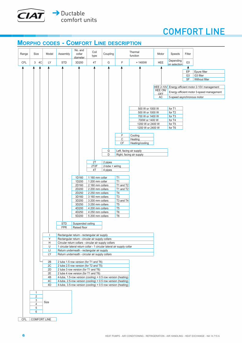
COMFORT LINEMORPHO CODES - COMFORT LINE DESCRIPTION
Range Size Model AssemblyNo. and
collar diameter
Coil type Coupling Thermal
function Motor Speeds Filter
CFL 3 4C LY STD 3D200 4T G F + 1400W HEE Depending on selection G3
EP ���������G3 ������SF ��������
HEE 2-10V ������������������������������������HEE ON/
OFF �������������������������������������AC 5-speed asynchronous motor
500 W or 1000 W for T1500 W or 1000 W for T2700 W or 1400 W for T3700W or 1400 W for T4
1200 W or 2400 W for T51200 W or 2400 W for T6
F CoolingC Heating
CF Heating/cooling
G Left, facing air supplyD Right, facing air supply
2T 2 pipes2T2F 2-tube + wiring
4T 4 pipes
1D160 1 160 mm collar T11D200 1 200 mm collar T12D160 2 160 mm collars T1 and T22D200 2 200 mm collars T1 and T22D250 2 250 mm collars T43D160 3 160 mm collars T3 3D200 3 200 mm collars T3 and T43D250 3 250 mm collars T54D200 4 200 mm collars T54D250 4 250 mm collars T65D200 5 200 mm collars T6
STD Suspended ceilingFPR �������!���
I Rectangular return - rectangular air supplyY Rectangular return - circular air supply collarsH Circular return collars - circular air supply collarsU 1 circular lateral return collar - 1 circular lateral air supply collarLI Return underneath - rectangular air supplyLY Return underneath - circular air supply collars
2B 2 tube 1.5 row version (for T1 and T6)2C 2 tube 2.5 row version (for T2 and T5)2D 2 tube 3 row version (for T1 and T6)2E 2 tube 4 row version (for T1 and T6)4B 4-tube, 1.5-row version (cooling) + 0.5 row version (heating)4C 4-tube, 2.5-row version (cooling) + 0.5 row version (heating)4D 4-tube, 3.5-row version (cooling) + 0.5 row version (heating)
1
Size
23456
CFL COMFORT LINE

7
CO
MFO
RT
LIN
E
HEAT PUMPS - AIR CONDITIONING - REFRIGERATION - AIR HANDLING - HEAT EXCHANGE - NA 14.715 A
Ductable comfort units
Frame� Galvanised panelling, zinc-nickel plated steel fastenings.Melamine resin insulation, springy open-cell foam, plus aluminium shield to prevent any dust build-up in the insulation and facilitate cleaning. M1 fire rating, thickness 15 mm.
Water coil � ���������������� �������� �� ��������������������� ����������������� �������� �� �������������������� ������������� �������� �������� �!������ ��"������ ���� !���
! �����������#$�����#&�� ������������;������<������gasket.
� ���=�""��������>� �������������������!���� ���?�������������������@�@�� ����J� K�� ������� ���@� �� "�������� ��� �Z[=�>� ��� K�� �����
pressure� ���\]����������������������"������^ - 4-tube application: 90°C - 2-tube application: 90°C - 2T/2-wire application: 55°C (min. air flow rate: 200 m3/h)
Electrical heater (230V- 50Hz) � ���_�������� ������������ ������� �������>� "����������� ���
the hydraulic coil outlet and providing excellent supply air temperature distribution.
� ����� "��������������"���������������������������������1 capsule temperature limiter with automatic reset.
Condensate drain pan � ���=�`{���������"�����""�� �������|��}�~���� ����� � �����������"���� ������"����������������������>�
designed to prevent any leaks or bypass.� ���?������������������������@������������������������
front of the device.� ��������������������^����}>��J>���������������������|
Fan motor assembly size 1 to 5 1 fan motor assembly fitted with:
� Fan1 or 2 HEE impeller(s), with CIAT exclusive High Energy Efficiency airfoil blades in self-extinguishable ABS (HB) with galvanised metal housing.
� HEE motorHigh energy efficiency motor enabling a reduction of up to 85% in electricity consumption.
HEE motor description:� ���K�`=� �K��������� `���������� =�������� ����������
technology offering more linear torque progression and a lower operating sound level than BLDC (Brushless Direct Current) technology,
� ��������>����"� �����>�����"���� ������!�>� ������"���� ������ �"������� ��� Z��Z�� ��� ����!!� �������
signal, without expansion board,� ����������������� ��@������"���� �����������������������>� ����?�_��������!�������"����������"���� ��"����!���"��������
alarm feedback via a Konnex protocol communication bus. (via V3000 controller),
� ���\��������������@��������������>� ���_�""�����Z���Z�������}Z�JZ��;|
Note: The minimum voltage required for start-up of the motor is 2V.
Or� Asynchronous motor:5-speed motor connected to terminal block
Asynchronous motor description:� ���_����>����"� �����>�����"���� ������!�>� ���"�������� " ����>� �������������>� ����������������� ��@������"���� �����������������������>� �������������������>� �����Z���Z�������}Z�JZ��;�!���|� ���������!!� ��� �����"����! ���|�
Size 6 fan motor assemblyHEE solution:2 fan motor assemblies fitted with:
� FanAluminium single impeller with forward-curved self-extinguishable airfoil blades, dynamically balanced dual inlet with galvanised metal housing.
� HEE motorHigh energy efficiency motor enabling a reduction of up to 85% in electricity consumption (see HEE motor description for sizes 1 to 5).
Electrics box� ���������� � ���� ���������>� ��������`K_���� ��� ����]>���� ��� ������>� ���"���� ��������������Z>� �������������� �����?������� ��� ���� ���������}ZZ��>�
depth 7.5 mm,� ��� ������������!��� ����������� ��� �� ���� �����|
Filtration available� Epure function� ���̀ �"���� ��������������� ��"��@�����"��� ����!����������
drawn into suspended ceilings.� ����� ��!����������������������!!� ��� ��!������!�������������
effective for PM of 2.5 microns: - Filter area: 10 times the intake surface area. - Low energy impact. - Improved service life. - M1 fire rating. - Easy access via 2 quick locks.
Or� ������]�����!������������������!����������@��"���������!����|� �������~��!!� ��� ��=���^�#�|� �������������^�\�|� ��������������!���|� ��������� ��������@������� ���� ��|
TECHNICAL DESCRIPTION

8 HEAT PUMPS - AIR CONDITIONING - REFRIGERATION - AIR HANDLING - HEAT EXCHANGE - NA 14.715 A
Ductable comfort units
COMFORT LINEPlenums� Galvanised panelling, zinc-nickel plated steel fastenings,� ABS (HB) collars clipped to the panelling,� supply plenum:� ������������"�����^������������������������>�!��]������"���
cell foam, plus aluminium shield to prevent any dust build-up in the insulation and facilitate cleaning. M1 fire rating, thickness 15 mm,
� return plenum:� ��������������"�����|
Standard wiring diagram without control � 2-tube application: 7349011.� 2-tube + electric application: 7349014.� 4-tube application: 7349012.
Securing the device� ���=<\�<�{�����������������"������!�������� �������������
4 threaded rods: with CIAT resilient mounts min. diameter 6 mm and max. diameter 8 mm, or without CIAT suspension diameter 8 mm to 10 mm.
Packaging � ���?���@��������"��������"���� ������������ ���"�!���|
Control� ������������������ ����� ��� ����������������>� �����Z������ZZ���� ����� �����>� �����ZZZ������������� ����� �����������>� ���=������ �������� ����� ��������<��^���<�>� ���!�������� ������^ R1: Fresh air managed by presence sensor, R+: Fresh air managed by CO2 sensor.
Accessories� Factory fitted:� ���=��������������"��">� ����������������� ������������������@�|
� Delivered separately:� �����ZZ����������� ����>� ������!������������ZZ����!������������������^ - flow rate 15/30/45 m3/h, - flow rate 60/75/90 m3/h,� �������������������> ����JZ���� �� ������ �� �������!�����!!���������>�� ���������"���]��������>���!��]����� ���� �����|
Options (contact us)� ������ ��� ������������ � ���� ����������""�����������|� ���������� � ���� ���� ������ "���� ���� !��� ���!��� ������@��
atmospheres (coastal locations or areas close to chemical industries).
� ����������"���������������|

9
CO
MFO
RT
LIN
E
HEAT PUMPS - AIR CONDITIONING - REFRIGERATION - AIR HANDLING - HEAT EXCHANGE - NA 14.715 A
Ductable comfort units
LINEAR CONCEPTSDimensions of sizes 1 to 5 unitsMODEL I
25 C
onde
nsat
e ou
tlet
F
FF
F
FE
E
E
E
E
T5
T1
T3
T4
T2
Air supply frontal view
Overall 73818 20
Heating hot water coil Cooling cold water coil L
J
Ove
rall
D
K
200
Overall A
No filter or G3 air filter or Epure
filter
B 20829
H
I
Dis
tanc
e be
twee
n m
ount
ing
axes
C
Condensate pump (option)
Electrics box
4x Oblongs 12x30Dist. between mounting axes 649Fresh air knockout Ø100 and Ø125
2626
192 88
Ø16
1313
COMFORT LINE Left connection(for COMFORT LINE with right
connection, all components: electrics box, coil, etc
are configured symmetrically).
A B C D E F G H I J K L (4T)Air Supply Air Supply C. Coil H. Coil Air
IntakeAir
Intake C. Coil H. Coil C. Coil H. Coil 3 rows 4 rows
T1 898 660 692 215 620 1701/2''
1/2''
600 160 128 128
3535
5555T2 245 200 190 160 160T3 1198 960 992 920 900T4 280 235 3/4'' 225 192 40 110 62T5 1498 1260 1292 1220 1200

10 HEAT PUMPS - AIR CONDITIONING - REFRIGERATION - AIR HANDLING - HEAT EXCHANGE - NA 14.715 A
Ductable comfort units
COMFORT LINE
Overall 804
18 50
Heating hot water coil Cooling cold water coil I
F
Ove
rall
D
H
230
Overall A
No filter or G3 air filter or Epure
filter
B 20829
J
K
Dis
tanc
e be
twee
n m
ount
ing
axes
C
Condensate pump (option)
Electrics box
COMFORT LINE Left connection(for COMFORT LINE with right
connection, all components: electrics box, coil, etc
are configured symmetrically).
4x Oblongs 12x30
Dist. between mounting axes 649Fresh air knockout Ø100 and Ø125
E E
E
E
E
E
E
E
E
T5
T12 collars
T11 collar
T3
T4
T2
MODEL Y - Collar Ø200 mm
Air supply frontal view
2626
192 88
Ø16
1313
Ø20
0
25 C
onde
nsat
e ou
tlet
A B C D E F G H I (4T) QtyC. Coil H. Coil C. Coil H. Coil C. Coil H. Coil 3 rows 4 rows collars
T1 (1V)898 660 692
215-
128 1281/2''
1/2'' 3535
5555
1T1 (2V)
330 2T2
245 160 160T3
1198 960 992 305 3T4
280 192 40 3/4'' 110 62T5 1498 1260 1292 310 4
11
CO
MFO
RT
LIN
E
HEAT PUMPS - AIR CONDITIONING - REFRIGERATION - AIR HANDLING - HEAT EXCHANGE - NA 14.715 A
Ductable comfort units
E
E
E
E
E
E
E
T5
T12 collars
T11 collar
T3
T4
T2
Overall 804
18 50
Heating hot water coil Cooling cold water coil I
F
Ove
rall
D
H
230
Dis
tanc
e be
twee
n m
ount
ing
axes
C
Condensate pump (option)
Electrics box
4x Oblongs 12x30
2626
192 88
Ø16
1313
ØL
Dist. between mounting axes 649Fresh air knockout Ø100 and Ø125
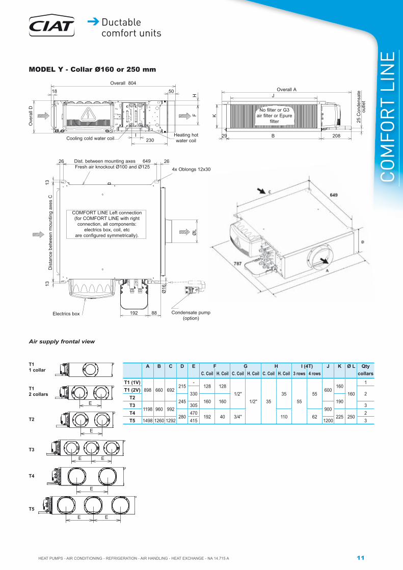
MODEL Y - Collar Ø160 or 250 mm
Air supply frontal view
COMFORT LINE Left connection(for COMFORT LINE with right
connection, all components: electrics box, coil, etc
are configured symmetrically).
Overall A
No filter or G3 air filter or Epure
filter
B 20829
J
K
25 C
onde
nsat
e ou
tlet
A B C D E F G H I (4T) J K Ø L QtyC. Coil H. Coil C. Coil H. Coil C. Coil H. Coil 3 rows 4 rows collars
T1 (1V)898 660 692
215-
128 1281/2''
1/2'' 3535
5555
600160
160
1T1 (2V)
330 2T2
245 160 160 190T3
1198 960 992305
9003
T4280
470192 40 3/4'' 110 62 225 250
2T5 1498 1260 1292 415 1200 3
12 HEAT PUMPS - AIR CONDITIONING - REFRIGERATION - AIR HANDLING - HEAT EXCHANGE - NA 14.715 A
Ductable comfort units
COMFORT LINE
109550 50
I
FH
230
No filter or G3 air filter or Epure
filter
Overall A
B 20829
25 C
onde
nsat
e ou
tlet
Dis
tanc
e be
twee
n m
ount
ing
axes
C
Condensate pump (option)Electrics box
4x Oblongs 12x30
2626
255
192 88 33
Ø16
1313
Ø20
0
Dist. between mounting axes 649Fresh air knockout Ø100 and Ø125
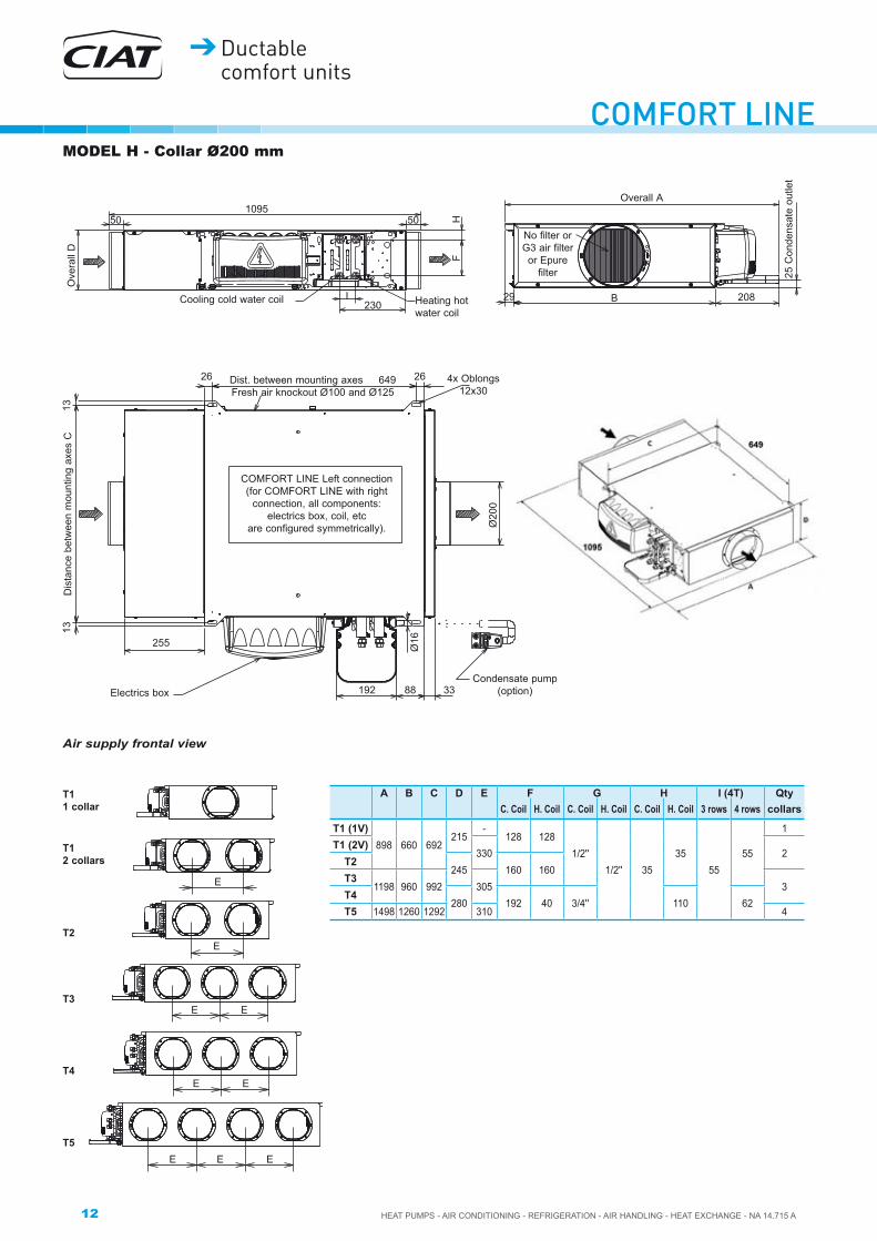
MODEL H - Collar Ø200 mm
Air supply frontal view
COMFORT LINE Left connection(for COMFORT LINE with right
connection, all components: electrics box, coil, etc
are configured symmetrically).
Ove
rall
D
Heating hot water coil
Cooling cold water coil
E E
E
E
E
E
E
E
E
T5
T3
T4
T2
T12 collars
T11 collar
A B C D E F G H I (4T) QtyC. Coil H. Coil C. Coil H. Coil C. Coil H. Coil 3 rows 4 rows collars
T1 (1V)898 660 692
215-
128 1281/2''
1/2'' 3535
5555
1T1 (2V)
330 2T2
245 160 160T3
1198 960 992 305 3T4
280 192 40 3/4'' 110 62T5 1498 1260 1292 310 4

13
CO
MFO
RT
LIN
E
HEAT PUMPS - AIR CONDITIONING - REFRIGERATION - AIR HANDLING - HEAT EXCHANGE - NA 14.715 A
Ductable comfort units
109550 50
I
FH
230
No filter or G3 air filter or
Epure filter
Overall A
B 20829
25 C
onde
nsat
e ou
tlet
Dis
tanc
e be
twee
n m
ount
ing
axes
C
Condensate pump (option)
Electrics box
4x Oblongs 12x30
2626
192 88
Ø1613
13
ØJ
Dist. between mounting axes 649
Fresh air knockout Ø100 and Ø125
MODEL H - Collar Ø160 or 250 mm
Air supply frontal view
COMFORT LINE Left connection(for COMFORT LINE with right
connection, all components: electrics box, coil, etc
are configured symmetrically).
Ove
rall
D
Heating hot water coilCooling cold water coil
E
E
E
E
E
E
E
T5
T3
T4
T2
T12 collars
T11 collar
A B C D E F G H I (4T) Ø J QtyC. Coil H. Coil C. Coil H. Coil C. Coil H. Coil 3 rows 4 rows collars
T1 (1V)898 660 692
215-
128 1281/2''
1/2'' 3535
5555 160
1T1 (2V)
330 2T2
245 160 160T3
1198 960 992305 3
T4280
470192 40 3/4'' 110 62 250
2T5 1498 1260 1292 415 3

14 HEAT PUMPS - AIR CONDITIONING - REFRIGERATION - AIR HANDLING - HEAT EXCHANGE - NA 14.715 A
Ductable comfort units
COMFORT LINE
Overall F
L
EJ
K
No filter or G3 air filter or
Epure filter
Overall A
B 208
25 C
onde
nsat
e ou
tlet
Dis
tanc
e be
twee
n m
ount
ing
axes
C
Condensate pump (option)Electrics box
4x Oblongs 12x30
2626ØH ØH
192 88
Ø16
1313 50
Dist. between mounting axes 649
Fresh air knockout Ø100 and Ø125
MODEL U - Collar Ø200 or 250 mm
COMFORT LINE Left connection(for COMFORT LINE with right
connection, all components: electrics box, coil, etc
are configured symmetrically).
Ove
rall
D
Heating hot water coilCooling cold water coil
ØH
A B C D E F G Ø H I J K L (4T)C. Coil H. Coil C. Coil H. Coil C. Coil H. Coil H. Coil 3 rows 4 rows
T1920 660 692
215 128 1281213 1/2''
1/2''200 956
3535 455
5555T2
245 160 160T3
1220 960 992T4 280 192 40 1313 3/4'' 250 1006 110 505 62

15
CO
MFO
RT
LIN
E
HEAT PUMPS - AIR CONDITIONING - REFRIGERATION - AIR HANDLING - HEAT EXCHANGE - NA 14.715 A
Ductable comfort units
MODEL Y - Collar Ø200 mm
Ove
rall
375
Overall 944#�������������� ���
#������ �������� ���
50
156
40
55235
18
Without filter or G3 air filter
or Epure filter
Overall 1498
25 C
onde
nsat
e ou
tlet
29
320
1260
1200
208
251 251 251 251
Air supply frontal view
Mounting hole spacing 788
Mou
ntin
g ho
le s
paci
ng 1
292
Electrics box
Fresh air knockoutØ 100 or Ø 125
Condensate pump (option)
1313
26 26
192 93.5 33
4 12 x 30 oblongs
5 x
Ø 2
00
Ø16
Overall 878 Overall 1498
Ove
rall
375
=�������� ����#�����
hot water coil G
����55
18
2052081260
1220
330
1200
320
29
20
156
40
Without filter or G3 air filter or
Epure filter
Air supply frontal view
Mounting hole spacing 788
Mou
ntin
g ho
le s
paci
ng 1
292
Electrics box
Fresh air knockout Ø100 or Ø125
Condensate pump
(option)
1313
26 26
192 93.5
4 12 x 30 oblongs
Ø16
Dimensions of size 6 unitsMODEL I
Size 6 available
1st quarter 2015

16 HEAT PUMPS - AIR CONDITIONING - REFRIGERATION - AIR HANDLING - HEAT EXCHANGE - NA 14.715 A
Ductable comfort units
COMFORT LINE
Overall 944
Ove
rall
375
#�������������� ���
#������ �������� ���
50
156
40
55235
18
Without filter or
G3 air filteror
Epure filter
Overall 1498
25 C
onde
nsat
e ou
tlet
29
320
1260
1200
208
300 300 300
Air supply frontal view
Mounting hole spacing 788
Mou
ntin
g ho
le s
paci
ng 1
292
Electrics box
Fresh air knockoutØ 100 or Ø 125
Condensate pump (option)
1313
26 26
192 93.5 33
4 12 x 30 oblongs
4 x
Ø 2
50
Ø16
MODEL Y - Collar 250 mm
MODEL H - Collar Ø 200 mm
The spacing and number of collars between the unit's inlet and outlet are identical
COMFORT LINE left connection.For COMFORT LINE with left connection all components (electrics boxes, coils, etc.) are arranged symmetrically.
Mounting hole spacing 788
Mou
ntin
g ho
le s
paci
ng 1
292
Electrics box
Fresh air knockout
Ø100 or Ø125
Condensate pump (option)
1313 26 26
192
255
93.5
4 12 x 30 oblongs
Ø16
5 x
Ø20
0
33
5 x
Ø20
0
Ove
rall
375
Overall 1232#�������������� ���
#������ �������� ���
50
156
40
55235
50
Air supply frontal view
151151 151 151
Without filter or G3 air filter or Epure filter
Overall 149825
Con
dens
ate
outle
t
29 1260 208

17
CO
MFO
RT
LIN
E
HEAT PUMPS - AIR CONDITIONING - REFRIGERATION - AIR HANDLING - HEAT EXCHANGE - NA 14.715 A
Ductable comfort units
MODEL H - Collar Ø 250 mm
Overall 1232#�������������� ���50
55
50
#������ �������� ���
4015
6
Ove
rall
375
H
235
Air supply frontal view
Without filter or with G3 air filter or Epure filter
Overall 1498
208126029
25 C
onde
nsat
e ou
tlet
Dis
t. be
twee
n m
ount
ing
axes
12
92
Condensate pump (option)
Electrics box
4x Oblongs 12x30
2626
192
300 300 300
255
93.5 33
Ø1613
13
4 x
Ø25
0
4 x
Ø25
0
Dist. between mounting axes 788
Fresh air knockout Ø100 or Ø125

18 HEAT PUMPS - AIR CONDITIONING - REFRIGERATION - AIR HANDLING - HEAT EXCHANGE - NA 14.715 A
Ductable comfort units
COMFORT LINE
G3 filter or Epure filter
Overall A
25 C
onde
nsat
e ou
tlet
M small grille T1 T2Frame 22
M large centred grille T3 T4 M large offset grille T3 T4
B 208Overall 721
Heating hot water coil
20
295
200
L
KJD
Grille I
Cooling cold water coil11
5M
ax. 75 Min
.
25 C
onde
nsat
e ou
tlet
Dis
tanc
e be
twee
n m
ount
ing
axes
C
Electrics box
4x Oblongs 12x30
2626
Fresh air knockout Ø100 and Ø125
192 88
Ø16
1313
Dist. between mounting axes 649
COMFORT LINE Left connection(for COMFORT LINE with right
connection, all components: electrics box, coil, etc
are configured symmetrically).
L CONCEPTS
MODEL LI
A A' B C DE F G
IJ K L (4T)
MAir supply
Air supply C. Coil H. Coil C. Coil H. Coil C. Coil H. Coil 3 rows 4 rows
T1898 660 692
215620
1701/2''
1/2'' 250
128 128
3535
3535
700T2
245 200 160 160T3
1205 1285 960 992 920 1195T4 280 235 3/4'' 192 40 110 62

19
CO
MFO
RT
LIN
E
HEAT PUMPS - AIR CONDITIONING - REFRIGERATION - AIR HANDLING - HEAT EXCHANGE - NA 14.715 A
Ductable comfort units
MODEL LIK
Overall 700192
75
E
min
.
max
.
Air recovery grille with integrated filter
115
Wall space H X I
30min.
295
D=
=
Sealing frame
Distance between mounting axes: 649
Dis
tanc
e be
twee
n m
ount
ing
axes
: C
Pre-punched for fresh air Ø 100 or 125
Insulated rectangular plenumto be provided by the client
Recovery pan for condensate
Diffusion grille
J x K sleeve
Electrics box
12 X 30 oblong
192 88
13
26
Overall A
25 C
onde
nsat
e ou
tlet
G small grille T1 T2Frame 22
G large centred grille T3 T4 G large offset grille T3 T4
B 208
A B C D E F G H I J K
T1898 660 692
215 200650 700
175625 620
170T2
245 230 205 200T3
1205 960 992 950 1195 925920
T4 280 265 240 235

20 HEAT PUMPS - AIR CONDITIONING - REFRIGERATION - AIR HANDLING - HEAT EXCHANGE - NA 14.715 A
Ductable comfort units
COMFORT LINEMODEL LY - Collar ø 200
MODEL LY - Collar ø 160
G3 filter or Epure filter
Overall A
25 C
onde
nsat
e ou
tlet
L small grille T1 T2Frame 22
L large centred grille T3 T4 L large offset grille T3 T4
B 208Overall 787
Heating hot water
coil
50
295
230I
HFD
Grille K
Cooling cold
water coil
115
Max
.75 Min
.
25 C
onde
nsat
e ou
tlet
Dis
tanc
e be
twee
n m
ount
ing
axes
C
Electrics boxCondensate
pump (option)
4x Oblongs 12x30
2626
Fresh air knockout Ø100 and Ø125
192 88
Ø16
Ø20
0
1313
Dist. between mounting axes 649
COMFORT LINE Left connection
(for COMFORT LINE with right connection, all components:
electrics box, coil, etc are configured symmetrically).
G3 filter or Epure filter
Overall A25
Con
dens
ate
outle
t
L small grille T1 T2Frame 22
L large centred grille T3 T4 L large offset grille T3 T4
B 208Overall 787
Heating hot water
coil
50
295
230I
HFD
Grille K
Cooling cold water
coil
115
Max
.75 Min
.
25 C
onde
nsat
e ou
tlet
Dis
tanc
e be
twee
n
mou
ntin
g ax
es C
Electrics box
Condensate pump (option)
4x Oblongs 12x30
26
Fresh air knockout Ø100 and Ø125
192 88
Ø16
Ø16
0
1313
Dist. between mounting axes 649
COMFORT LINE Left connection
(for COMFORT LINE with right connection, all components:
electrics box, coil, etc are configured symmetrically).
26
NOTE: For COMFORT LINE LY Ø160, sizes 3 and 4, speed 5 must not be selected (air flow too high for Ø160 collars).
A A' B C D E F G H I (4T) K LC. Coil H. Coil C. Coil H. Coil C. Coil H. Coil 3 rows 4 rowsT1 (1V)
898 660 692 215 128 1281/2'' 1/2'' 35 35 55 55 250
700T1 (2V) 330T2 245 160 160T3 1205 1285 960 992 305 1195T4 280 192 192 3/4'' 110 62
A A' B C D E F G H I (4T) K LC. Coil H. Coil C. Coil H. Coil C. Coil H. Coil 3 rows 4 rowsT1 (1V)
898 660 692 215 128 1281/2'' 1/2'' 35 35 55 55 250
700T1 (2V) 330T2 245 160 160T3 1205 1285 960 992 305 1195T4 280 192 192 3/4'' 110 62

21
CO
MFO
RT
LIN
E
HEAT PUMPS - AIR CONDITIONING - REFRIGERATION - AIR HANDLING - HEAT EXCHANGE - NA 14.715 A
Ductable comfort units
MODEL LYK
Overall A
25 C
onde
nsat
e ou
tlet
G small grille T1 T2Frame 22
G large centred grille T3 T4 G large offset grille T3 T4
208B
Pre-punched for fresh air Ø 100 or 125 Pre-punched for
fresh air Ø 100
Electrics box
Condensate drain pan
Distance between mounting axes: 649
1, 2 or 3 ducts depending on the size of the unit D
ista
nce
betw
een
mou
ntin
g ax
es: C
12 x 30 oblong
Wall space H x I
Ø 160 collar
26 1000 approx.
F
13
120
120
192
Overall 735192
295
D E
75
min
.
115
max
.
Air recovery grille with integrated filter
30 min.120 max.
Telescopic sleeve
Diffusion grille
Diffusion kit
J x K plenum
Ø 160 collar
NOTE: For COMFORT LINE LY Ø160, sizes 3 and 4, speed 5 must not be selected (air flow too high for Ø160 collars).
A B C D E F G H I J K No. of ducts
T1 (1V)898 660 692
215 200650 700
175625
180
440 1T1 (2V)
640 2T2 (2V)
245 230 205T3 (3V)
1205 960 992 950 1195 925 840 3T4 (3V) 280 265 240

22 HEAT PUMPS - AIR CONDITIONING - REFRIGERATION - AIR HANDLING - HEAT EXCHANGE - NA 14.715 A
Ductable comfort units
COMFORT LINEReturn grille adjustment Sizes 1 and 2: 700 grille on 700 frame Sizes 3 and 4: grille on 1200 frame
Vertical adjustment only:
1) Open the grille fully using the 2 clips. 2) Remove the grille + the filter completely. 3) Unscrew the 4 screws (see the view below) then adjust
the height with the adjustment holes, then refit the screws. 4) Cover over the adjustment holes with aluminium tape.
4 screws
1) 2)
3) 4) 5)
Sizes 1 and 2: 700 grille on 1200 frame
Vertical adjustment (see above)
Horizontal adjustment:
1) Open the grille using the 2 clips. 2) Remove the grille + the filter completely. 3) Undo the 4 screws. 4) Move the support panel. 5) Refit the 4 screws.
SUMMARY OF COLLAR NUMBERS FOR MODELS Y, H AND LYSize Collar(s) Ø 160 Collar(s) Ø 200 Collar(s) Ø 250
T1
T2
T3
T4
T5
T6
or or

23
CO
MFO
RT
LIN
E
HEAT PUMPS - AIR CONDITIONING - REFRIGERATION - AIR HANDLING - HEAT EXCHANGE - NA 14.715 A
Ductable comfort units
WEIGHT
HYDRAULIC CONNECTIONS WITH FITTED VALVES
Heating/cooling assembly for valves with 3-point or thermal actuators
2-way valve
2-way valve
4-way valve
4-way valve
2-way valve4-way valve
O-ring O-ring
OutletOutlet
InletInlet
Sizes 1 - 2 - 3
Sizes 4 - 5
Cooling
Cooling
Cooling
Cooling
Heating
Heating
Heating
Heating
COMFORT LINEWeight (kg)
T1 T2 T3 T4 T5 T6
I 25 27 36 39 47 65
Y 27 29 39 42 51 69
H 34 34 46 49 60 78
U 35 38 51 57 - -
LI 31 33 44 47 - -
LY 33 35 47 50 - -

24 HEAT PUMPS - AIR CONDITIONING - REFRIGERATION - AIR HANDLING - HEAT EXCHANGE - NA 14.715 A
Ductable comfort units
COMFORT LINE2-way valve4-way valve
O-ring O-ring
Outlet Outlet
Outlet
Inlet Inlet
Inlet
2-way valve4-way valve
Size 6
Cooling Cooling Heating Heating
O-ring O-ring
Outlet Outlet
Inlet Inlet

25
CO
MFO
RT
LIN
E
HEAT PUMPS - AIR CONDITIONING - REFRIGERATION - AIR HANDLING - HEAT EXCHANGE - NA 14.715 A
Ductable comfort units
FLEXIBLE COUPLING KIT (OPTIONAL) WITH VALVES OR ON THE UNITASSEMBLY WITHOUT VALVES
ASSEMBLY WITH 2-WAY VALVES
ASSEMBLY WITH 4-WAY VALVES
TECHNICAL DESCRIPTION- Machined brass coupling unless otherwise specifiedThread and internal thread in line with standards NFE 03-004 and NFE 03-005.- Pipe in EPDM elastomer in line with EN 684-1 and AISI 304 stainless steel sheath.- Stainless steel crimped bush between coupling and tube + sheath.
- Heat insulating sheath in M1 cellular foam (9 mm thick) glued at each end to the crimping bush.
- Protective end-piece glued at each end to the heat insulating sheath.
- DN corresponds to the pipe's internal diameter.- Min./max. operating temperature = 6°C to 110°C.- Max. operating pressure 110°C.
Only on cold insulated
flexible couplings
Female rotary couplings �������! ���#��������#�����>� ������������
Male cylindrical couplings �������! ���#��������
#�����>����������
Female rotary couplings with
���! ���#��������#�����>�
unit side (on valves)
\��� ������� ���]��� ��"�������������! ��
�#��������#�����>����������(on coil connections)Female rotary couplings
�������! ���#��������#�����>� ������������
Female rotary couplings with ���! ���#��������#�����>�
unit side (on valves)
Female rotary couplings with ���! ���#��������#�����>�
customer side

26 HEAT PUMPS - AIR CONDITIONING - REFRIGERATION - AIR HANDLING - HEAT EXCHANGE - NA 14.715 A
Ductable comfort units
COMFORT LINE
12
Electrical heater1 1 capillary tube temperature limiter with manual reset .
2 1 capsule temperature limiter with automatic reset.
Name plate
TECHNICAL CHARACTERISTICSCondensate drain pump
Technical specifications:
���\]�����!��������!��Z����!����"��"������������!�Z�������������]�����pipe length of 5 metres.
���\]�����!��������!��~����!����"��"������������!�Z�������������]�����pipe length of 10 metres.
Table of actual pump flow rates with Ø 6 mm PVC tube:
Name plate of the unit
The name plate contains all the information required to identify the unit and its configuration. This plate is always mounted on the face opposite the electrics box.
-1- Code,-2- serial number, -3- unit designation, -4- rated motor output,-5- motor rotation speed,-6- coil type,-7- wiring diagram reference,-8- motor speed wiring, -9- maximum operating pressure,-10- electric heater specifications (if fitted).
1 2 3
4
5
6 7
8
9
10
Discharge height
Total pipe length (internal Ø 6mm) 5 m 10 m 20 m 30 m(l/h) (l/h) (l/h) (l/h)
0 m 20 19 18 17
2 m 16 15 14 13.5
4 m 11.5 11 10.5 10
6 m 8.5 7.5 6.5
8 m 6 5 4
10 m 4 3.5 2.5

27
CO
MFO
RT
LIN
E
HEAT PUMPS - AIR CONDITIONING - REFRIGERATION - AIR HANDLING - HEAT EXCHANGE - NA 14.715 A
Ductable comfort units
Coil contents
Diameters of coil couplingsCoil coupling type: flat end swivel nuts with a female thread��@��������� ��"�������"�^��������������� ��"����������������
Motor electrical specifications
CONDITIONS: Maximum values with outlet open. _�""���@��������Z�����Z����}Z�JZ�;|
COMFORT LINE Motor speed
AC asynchronous motor HEE Brushless motor
T1 T2 T3 T4 T5 T1 T2 T3 T4 T5 T6
Power input (W)
V5 74 119 166 180 223 37 72 113 97 172 343V4 48 104 124 125 192 22 54 47 38 117 330V3 42 88 111 110 163 14 36 27 22 67 307V2 36 67 96 95 149 8 14 14 13 36 178V1 34 51 93 90 129 5 6 9 8 17 110
Input current (A)
V5 0.32 0.53 0.7 0.77 0.95 0.25 0.47 0.69 0.61 1.06 2.59V4 0.22 0.45 0.52 0.53 0.81 0.16 0.36 0.3 0.25 0.73 2.36V3 0.2 0.38 0.47 0.48 0.69 0.11 0.25 0.18 0.15 0.43 2.22V2 0.18 0.29 0.42 0.42 0.64 0.07 0.11 0.1 0.1 0.24 1.32V1 0.18 0.22 0.41 0.4 0.57 0.06 0.06 0.07 0.07 0.12 0.75
2-tube coil (L)
4-tube coil (L)
Cold water coil
Hot water coil
12B 0.47312D 0.64112E 0.89414B 0.473 0.17914D 0.641 0.26422C 0.65222D 0.82422E 1.07224C 0.652 0.1824D 0.82 0.26432C 0.90832D 1.14932E 1.51134C 0.908 0.25334D 1.149 0.37342C 1.942D 2.33942E 3.21744C 1.9 0.45944D 2.339 0.45952C 2.4352D 3.0052E 4.14854C 2.432 0.5954D 3.00 0.5962B 3.06562D 4.49562E 5.92564B 3.065 1.63564D 4.495 1.635
COMFORT LINE Size 1 Size 2 Size 3 Size 4 Size 5 Size 6
2-tubes system Hot water or cold water coil G1/2'' G1/2'' G1/2'' G3/4'' G3/4'' G3/4''
4-tubes systemCold water coil G1/2'' G1/2'' G1/2'' G3/4'' G3/4'' G3/4''Hot water coil G1/2'' G1/2'' G1/2'' G1/2'' G1/2'' G3/4''

28 HEAT PUMPS - AIR CONDITIONING - REFRIGERATION - AIR HANDLING - HEAT EXCHANGE - NA 14.715 A
Ductable comfort units
COMFORT LINEPERFORMANCEMODEL ICold water temperature: 7/12°C, summer air temperature: 27°C - 19°C (WB)Hot water temperature: 70/60°C, summer air temperature: 20°C - 50% (RH)
COMFORT LINE
Model I
Motor code
������� in m3/h
Available static
pressure (1)
Cooling cap. W Heating capacity
W
Sound power LW
dB(A)
Comfort level ISO
or NR
Average air temperature rise in K (2)
Auxiliary electric heater 230/1/50Total Sensible
500W 1000W
12B
V5 455 1 710 1 640 5 110 59 38 3.3 6.5V4 375 1 500 1 420 4 460 54 32 4.0 7.9V3 310 10 1 300 1 210 3 910 49 27 4.8 9.6V2 230 1 010 938 3 190 42 19 6.5 12.9V1 165 771 696 2 410 35 <15 9.0 18.0
12D
V5 455 2 220 1 930 5 750 59 38 3.3 6.5V4 375 1 930 1 650 4 950 54 32 4.0 7.9V3 310 10 1 670 1 400 4 270 49 27 4.8 9.6V2 230 1 310 1 070 3 400 42 19 6.5 12.9V1 165 958 775 2 520 35 <15 9.0 18.0
12E
V5 455 2 690 2 160 6 240 59 38 3.3 6.5V4 375 2 320 1 830 5 300 54 32 4.0 7.9V3 310 10 2 000 1 540 4 520 49 27 4.8 9.6V2 230 1 560 1 180 3 510 42 19 6.5 12.9V1 165 1 150 852 2 560 35 <15 9.0 18.0
14B
V5 455 1 710 1 640 3 040 59 38 3.3 6.5V4 375 1 500 1 420 2 760 54 32 4.0 7.9V3 310 10 1 300 1 210 2 500 49 27 4.8 9.6V2 230 1 010 939 2 110 42 19 6.5 12.9V1 165 771 697 1 700 35 <15 9.0 18.0
14D
V5 455 2 270 1 960 4 350 59 38 3.3 6.5V4 375 1 970 1 660 3 840 54 32 4.0 7.9V3 310 10 1 700 1 410 3 360 49 27 4.8 9.6V2 230 1 330 1 080 2 710 42 19 6.5 12.9V1 165 966 780 2 060 35 <15 9.0 18.0
500W 1000W
22C
V5 730 3 340 3 100 9 100 62 40 2.0 4.1V4 670 3 130 2 870 8 500 60 37 2.2 4.4V3 580 10 2 830 2 540 7 640 56 34 2.6 5.1V2 395 2 080 1 780 5 550 47 24 3.8 7.5V1 230 1 300 1 060 3 420 35 <15 6.5 12.9
22D
V5 730 3 870 3 340 9 750 62 40 2.0 4.1V4 670 3 600 3 070 9 050 60 37 2.2 4.4V3 580 10 3 250 2 710 8 050 56 34 2.6 5.1V2 395 2 360 1 890 5 690 47 24 3.8 7.5V1 230 1 460 1 130 3 410 35 <15 6.5 12.9
22E
V5 730 4 190 3 460 10 000 62 40 2.0 4.1V4 670 3 920 3 200 9 330 60 37 2.2 4.4V3 580 10 3 530 2 820 8 300 56 34 2.6 5.1V2 395 2 570 1 980 5 880 47 24 3.8 7.5V1 230 1 600 1 180 3 540 35 <15 6.5 12.9
24C
V5 730 3 340 3 100 3 660 62 40 2.0 4.1V4 670 3 130 2 870 3 540 60 37 2.2 4.4V3 580 10 2 830 2 540 3 340 56 34 2.6 5.1V2 395 2 080 1 780 2 790 47 24 3.8 7.5V1 230 1 300 1 060 2 050 35 <15 6.5 12.9
24D
V5 730 3 960 3 380 5 000 62 40 2.0 4.1V4 670 3 700 3 120 4 810 60 37 2.2 4.4V3 580 10 3 310 2 740 4 520 56 34 2.6 5.1V2 395 2 400 1 910 3 700 47 24 3.8 7.5V1 230 1 470 1 140 2 630 35 <15 6.5 12.9
700W 1400W
32C
V5 1 145 5 170 4 620 14 800 64 41 1.8 3.6V4 875 4 380 3 760 11 700 58 35 2.4 4.8V3 710 10 3 820 3 190 9 750 54 31 2.9 5.9V2 525 3 060 2 470 7 350 48 25 4.0 7.9V1 400 2 500 1 960 5 750 44 21 5.2 10.4
32D
V5 1 145 5 770 4 980 15 900 64 41 1.8 3.6V4 875 4 780 3 990 12 600 58 35 2.4 4.8V3 710 10 4 110 3 350 10 400 54 31 2.9 5.9V2 525 3 240 2 550 7 770 48 25 4.0 7.9V1 400 2 610 2 010 6 050 44 21 5.2 10.4
32E
V5 1 145 6 010 5 050 16 000 64 41 1.8 3.6V4 875 4 970 4 040 12 500 58 35 2.4 4.8V3 710 10 4 260 3 390 10 300 54 31 2.9 5.9V2 525 3 340 2 590 7 690 48 25 4.0 7.9V1 400 2 690 2 040 5 970 44 21 5.2 10.4
34C
V5 1 145 5 170 4 630 5 840 64 41 1.8 3.6V4 875 4 380 3 770 5 200 58 35 2.4 4.8V3 710 10 3 820 3 200 4 700 54 31 2.9 5.9V2 525 3 060 2 480 3 990 48 25 4.0 7.9V1 400 2 500 1 970 3 410 44 21 5.2 10.4
34D
V5 1 145 5 940 5 070 7 890 64 41 1.8 3.6V4 875 4 900 4 050 6 920 58 35 2.4 4.8V3 710 10 4 190 3 380 6 190 54 31 2.9 5.9V2 525 3 280 2 580 5 160 48 25 4.0 7.9V1 400 2 640 2 030 4 360 44 21 5.2 10.4

29
CO
MFO
RT
LIN
E
HEAT PUMPS - AIR CONDITIONING - REFRIGERATION - AIR HANDLING - HEAT EXCHANGE - NA 14.715 A
Ductable comfort units
(1) Static pressures given for information purposes. For higher available static pressures, consult our sales office.Model I sound level: Table for devices with ducted intake and discharge, with room and installation attenuation of 18 dB (size 1 to 3) 20 dB (size 4 to 5) and 23 dB (size 6). If the device is not ducted on the intake, add 6 dB to the comfort levels above.(2) Important: the temperature should not exceed 65°C (CIAT recommendation).
MODEL ICOMFORT
LINE Model I
Motor code ������� in m3/h
Available static
pressure (1)
Cooling cap. W Heating capacity
W
Sound power LW
dB(A)
Comfort level (ISO or NR)
Average air temperature rise in K (2)
Auxiliary electric heater 230/1/50Total Sensible
700W 1400W
42C
V5 1 210 6 090 5 360 15 800 64 39 1.7 3.4V4 880 4 900 4 070 12 100 57 32 2.4 4.7V3 710 10 4 180 3 370 10 000 53 28 2.9 5.9V2 530 3 330 2 600 7 690 48 23 3.9 7.8V1 400 2 650 2 010 5 950 43 19 5.2 10.4
42D
V5 1 210 7 070 5 780 16 900 64 39 1.7 3.4V4 880 5 610 4 370 12 700 57 32 2.4 4.7V3 710 10 4 730 3 600 10 500 53 28 2.9 5.9V2 530 3 710 2 760 7 970 48 23 3.9 7.8V1 400 2 920 2 130 6 120 43 19 5.2 10.4
42E
V5 1 210 7 550 5 970 17 200 64 39 1.7 3.4V4 880 5 910 4 500 12 900 57 32 2.4 4.7V3 710 10 4 970 3 700 10 600 53 28 2.9 5.9V2 530 3 880 2 830 8 010 48 23 3.9 7.8V1 400 3 040 2 180 6 150 43 19 5.2 10.4
44C
V5 1 210 6 090 5 370 6 530 64 39 1.7 3.4V4 880 4 900 4 080 5 650 57 32 2.4 4.7V3 710 10 4 180 3 380 5 070 53 28 2.9 5.9V2 530 3 330 2 610 4 310 48 23 3.9 7.8V1 400 2 650 2 020 3 640 43 19 5.2 10.4
44D
V5 1 210 7 180 5 840 6 510 64 39 1.7 3.4V4 880 5 690 4 420 5 610 57 32 2.4 4.7V3 710 10 4 790 3 640 5 010 53 28 2.9 5.9V2 530 3 750 2 780 4 250 48 23 3.9 7.8V1 400 2 940 2 150 3 580 43 19 5.2 10.4
1200W 2400W
52C
V5 1 595 8 000 6 830 19 800 68 43 2.2 4.5V4 1 440 7 490 6 300 18 400 66 40 2.5 5.0V3 1 240 10 6 790 5 580 16 300 62 36 2.9 5.7V2 1 010 5 890 4 700 13 800 57 32 3.5 7.1V1 720 4 590 3 520 10 400 51 26 5.0 9.9
52D
V5 1 595 8 620 7 200 21 200 68 43 2.2 4.5V4 1 440 8 030 6 610 19 500 66 40 2.5 5.0V3 1 240 10 7 190 5 800 17 300 62 36 2.9 5.7V2 1 010 6 150 4 850 14 500 57 32 3.5 7.1V1 720 4 710 3 600 10 800 51 26 5.0 9.9
52E
V5 1 595 10 000 7 830 22 500 68 43 2.2 4.5V4 1 440 9 270 7 160 20 700 66 40 2.5 5.0V3 1 240 10 8 240 6 260 18 200 62 36 2.9 5.7V2 1 010 6 970 5 200 15 100 57 32 3.5 7.1V1 720 5 270 3 840 11 100 51 26 5.0 9.9
54C
V5 1 595 8 000 6 840 8 510 68 43 2.2 4.5V4 1 440 7 490 6 310 8 180 66 40 2.5 5.0V3 1 240 10 6 790 5 590 7 680 62 36 2.9 5.7V2 1 010 5 890 4 710 6 980 57 32 3.5 7.1V1 720 4 590 3 530 5 870 51 26 5.0 9.9
54D
V5 1 595 8 960 7 380 8 470 68 43 2.2 4.5V4 1 440 8 310 6 760 8 130 66 40 2.5 5.0V3 1 240 10 7 430 5 930 7 610 62 36 2.9 5.7V2 1 010 6 330 4 940 6 900 57 32 3.5 7.1V1 720 4 830 3 670 5 790 51 26 5.0 9.9
1200W 2400W
62B
V5 3 005 12 500 11 100 32 300 76 49 1.2 2.4V4 2 880 12 200 10 800 31 400 73 46 1.2 2.5V3 2 710 10 11 800 10 400 30 100 71 44 1.3 2.6V2 2 215 10 400 8 970 26 200 67 40 1.6 3.2V1 1 870 9 300 7 920 23 200 63 37 1.9 3.8
62D
V5 3 005 15 500 13 000 37 200 76 49 1.2 2.4V4 2 880 15 100 12 500 36 000 73 46 1.2 2.5V3 2 710 10 14 500 12 000 34 400 71 44 1.3 2.6V2 2 215 12 600 10 200 29 500 67 40 1.6 3.2V1 1 870 11 200 8 900 25 800 63 37 1.9 3.8
62E
V5 3 005 18 200 14 400 41 200 76 49 1.2 2.4V4 2 880 17 600 13 900 39 800 73 46 1.2 2.5V3 2 710 10 16 900 13 200 37 800 71 44 1.3 2.6V2 2 215 14 500 11 100 32 000 67 40 1.6 3.2V1 1 870 12 700 9 600 27 600 63 37 1.9 3.8
64B
V5 3 005 12 500 11 100 21 900 76 49 1.2 2.4V4 2 880 12 200 10 800 21 500 73 46 1.2 2.5V3 2 710 10 11 800 10 400 20 800 71 44 1.3 2.6V2 2 215 10 400 8 990 18 700 67 40 1.6 3.2V1 1 870 9 300 7 940 17 000 63 37 1.9 3.8
64D
V5 3 005 16 000 13 300 21 900 76 49 1.2 2.4V4 2 835 15 400 12 700 21 300 73 46 1.3 2.5V3 2 710 10 14 900 12 200 20 800 71 44 1.3 2.6V2 2 215 13 000 10 400 18 600 67 40 1.6 3.2V1 1 870 11 500 9 060 16 900 63 37 1.9 3.8
30 HEAT PUMPS - AIR CONDITIONING - REFRIGERATION - AIR HANDLING - HEAT EXCHANGE - NA 14.715 A
Ductable comfort units
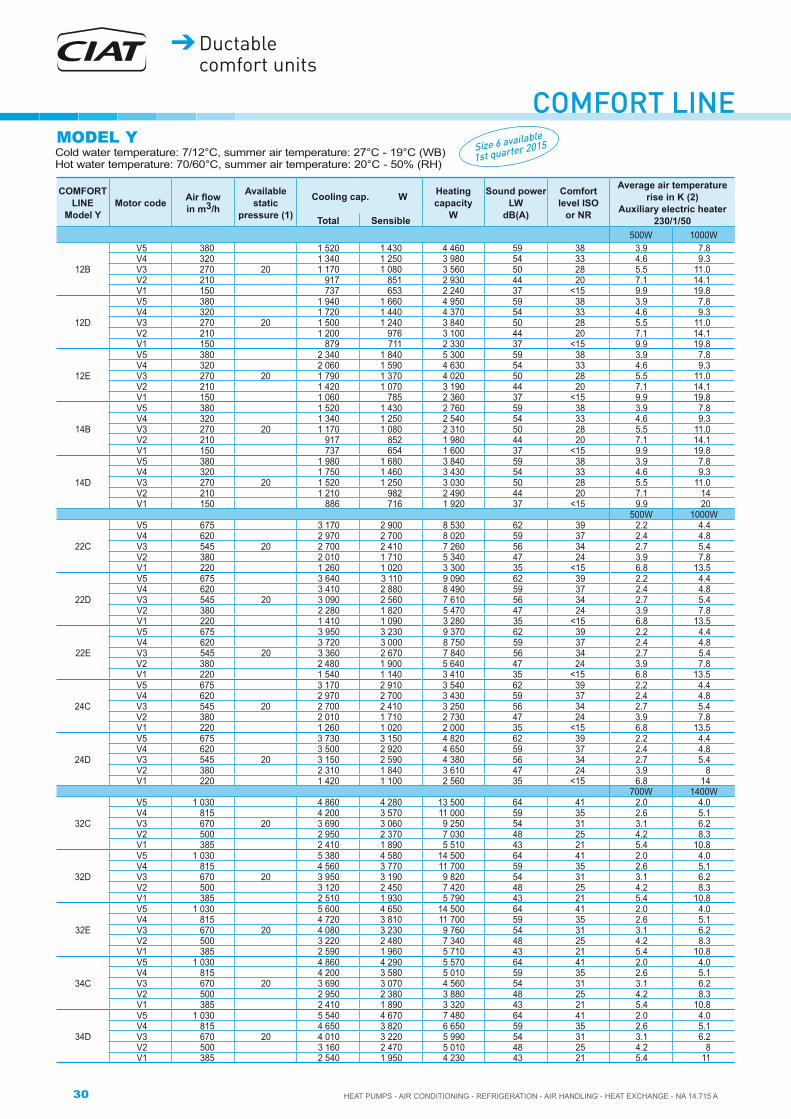
COMFORT LINECold water temperature: 7/12°C, summer air temperature: 27°C - 19°C (WB)Hot water temperature: 70/60°C, summer air temperature: 20°C - 50% (RH)
MODEL Y
COMFORT LINE
Model YMotor code �������
in m3/h
Available static
pressure (1)
Cooling cap. W Heating capacity
W
Sound power LW
dB(A)
Comfort level ISO
or NR
Average air temperature rise in K (2)
Auxiliary electric heater 230/1/50Total Sensible
500W 1000W
12B
V5 380 1 520 1 430 4 460 59 38 3.9 7.8V4 320 1 340 1 250 3 980 54 33 4.6 9.3V3 270 20 1 170 1 080 3 560 50 28 5.5 11.0V2 210 917 851 2 930 44 20 7.1 14.1V1 150 737 653 2 240 37 <15 9.9 19.8
12D
V5 380 1 940 1 660 4 950 59 38 3.9 7.8V4 320 1 720 1 440 4 370 54 33 4.6 9.3V3 270 20 1 500 1 240 3 840 50 28 5.5 11.0V2 210 1 200 976 3 100 44 20 7.1 14.1V1 150 879 711 2 330 37 <15 9.9 19.8
12E
V5 380 2 340 1 840 5 300 59 38 3.9 7.8V4 320 2 060 1 590 4 630 54 33 4.6 9.3V3 270 20 1 790 1 370 4 020 50 28 5.5 11.0V2 210 1 420 1 070 3 190 44 20 7.1 14.1V1 150 1 060 785 2 360 37 <15 9.9 19.8
14B
V5 380 1 520 1 430 2 760 59 38 3.9 7.8V4 320 1 340 1 250 2 540 54 33 4.6 9.3V3 270 20 1 170 1 080 2 310 50 28 5.5 11.0V2 210 917 852 1 980 44 20 7.1 14.1V1 150 737 654 1 600 37 <15 9.9 19.8
14D
V5 380 1 980 1 680 3 840 59 38 3.9 7.8V4 320 1 750 1 460 3 430 54 33 4.6 9.3V3 270 20 1 520 1 250 3 030 50 28 5.5 11.0V2 210 1 210 982 2 490 44 20 7.1 14V1 150 886 716 1 920 37 <15 9.9 20
500W 1000W
22C
V5 675 3 170 2 900 8 530 62 39 2.2 4.4V4 620 2 970 2 700 8 020 59 37 2.4 4.8V3 545 20 2 700 2 410 7 260 56 34 2.7 5.4V2 380 2 010 1 710 5 340 47 24 3.9 7.8V1 220 1 260 1 020 3 300 35 <15 6.8 13.5
22D
V5 675 3 640 3 110 9 090 62 39 2.2 4.4V4 620 3 410 2 880 8 490 59 37 2.4 4.8V3 545 20 3 090 2 560 7 610 56 34 2.7 5.4V2 380 2 280 1 820 5 470 47 24 3.9 7.8V1 220 1 410 1 090 3 280 35 <15 6.8 13.5
22E
V5 675 3 950 3 230 9 370 62 39 2.2 4.4V4 620 3 720 3 000 8 750 59 37 2.4 4.8V3 545 20 3 360 2 670 7 840 56 34 2.7 5.4V2 380 2 480 1 900 5 640 47 24 3.9 7.8V1 220 1 540 1 140 3 410 35 <15 6.8 13.5
24C
V5 675 3 170 2 910 3 540 62 39 2.2 4.4V4 620 2 970 2 700 3 430 59 37 2.4 4.8V3 545 20 2 700 2 410 3 250 56 34 2.7 5.4V2 380 2 010 1 710 2 730 47 24 3.9 7.8V1 220 1 260 1 020 2 000 35 <15 6.8 13.5
24D
V5 675 3 730 3 150 4 820 62 39 2.2 4.4V4 620 3 500 2 920 4 650 59 37 2.4 4.8V3 545 20 3 150 2 590 4 380 56 34 2.7 5.4V2 380 2 310 1 840 3 610 47 24 3.9 8V1 220 1 420 1 100 2 560 35 <15 6.8 14
700W 1400W
32C
V5 1 030 4 860 4 280 13 500 64 41 2.0 4.0V4 815 4 200 3 570 11 000 59 35 2.6 5.1V3 670 20 3 690 3 060 9 250 54 31 3.1 6.2V2 500 2 950 2 370 7 030 48 25 4.2 8.3V1 385 2 410 1 890 5 510 43 21 5.4 10.8
32D
V5 1 030 5 380 4 580 14 500 64 41 2.0 4.0V4 815 4 560 3 770 11 700 59 35 2.6 5.1V3 670 20 3 950 3 190 9 820 54 31 3.1 6.2V2 500 3 120 2 450 7 420 48 25 4.2 8.3V1 385 2 510 1 930 5 790 43 21 5.4 10.8
32E
V5 1 030 5 600 4 650 14 500 64 41 2.0 4.0V4 815 4 720 3 810 11 700 59 35 2.6 5.1V3 670 20 4 080 3 230 9 760 54 31 3.1 6.2V2 500 3 220 2 480 7 340 48 25 4.2 8.3V1 385 2 590 1 960 5 710 43 21 5.4 10.8
34C
V5 1 030 4 860 4 290 5 570 64 41 2.0 4.0V4 815 4 200 3 580 5 010 59 35 2.6 5.1V3 670 20 3 690 3 070 4 560 54 31 3.1 6.2V2 500 2 950 2 380 3 880 48 25 4.2 8.3V1 385 2 410 1 890 3 320 43 21 5.4 10.8
34D
V5 1 030 5 540 4 670 7 480 64 41 2.0 4.0V4 815 4 650 3 820 6 650 59 35 2.6 5.1V3 670 20 4 010 3 220 5 990 54 31 3.1 6.2V2 500 3 160 2 470 5 010 48 25 4.2 8V1 385 2 540 1 950 4 230 43 21 5.4 11
Size 6 available
1st quarter 2015

31
CO
MFO
RT
LIN
E
HEAT PUMPS - AIR CONDITIONING - REFRIGERATION - AIR HANDLING - HEAT EXCHANGE - NA 14.715 A
Ductable comfort units
MODEL Y
(1) Static pressures given for information purposes. For higher available static pressures, consult our sales office.
Model Y sound level: Table for devices with ducted intake and discharge, with room and installation attenuation of 18 dB (size 1 to 3) 20 dB (size 4 to 5) and 23 dB (size 6). If the device is not ducted on the intake, add 4 dB to the comfort levels above.
(2) Important: the temperature should not exceed 65°C (CIAT recommendation)
Size 6 available
1st quarter 2015
COMFORT LINE
Model Y
Motor code
������� in m3/h
Available static
pressure (1)
Cooling cap. W Heating capacity
W
Sound power LW
dB(A)
Comfort level ISO
or NR
Average air temperature rise in K (2)
Auxiliary electric heater 230/1/50Total Sensible
700W 1400W
42C
V5 1 115 5 800 5 020 14 700 63 39 1.9 3.7V4 830 4 700 3 870 11 500 57 32 2.5 5.0V3 680 20 4 050 3 240 9 600 53 28 3.1 6.1V2 505 3 220 2 500 7 390 47 23 4.1 8.2V1 385 2 560 1 940 5 740 43 19 5.4 10.8
42D
V5 1 115 6 680 5 390 15 600 63 39 1.9 3.7V4 830 5 370 4 160 12 100 57 32 2.5 5.0V3 680 20 4 560 3 460 10 000 53 28 3.1 6.1V2 505 3 580 2 660 7 650 47 23 4.1 8.2V1 385 2 820 2 060 5 900 43 19 5.4 10.8
42E
V5 1 115 7 110 5 560 15 900 63 39 1.9 3.7V4 830 5 660 4 280 12 200 57 32 2.5 5.0V3 680 20 4 790 3 560 10 100 53 28 3.1 6.1V2 505 3 740 2 720 7 690 47 23 4.1 8.2V1 385 2 940 2 110 5 920 43 19 5.4 10.8
44C
V5 1 115 5 800 5 020 6 290 63 39 1.9 3.7V4 830 4 700 3 880 5 490 57 32 2.5 5.0V3 680 20 4 050 3 250 4 950 53 28 3.1 6.1V2 505 3 220 2 510 4 200 47 23 4.1 8.2V1 385 2 560 1 950 3 550 43 19 5.4 10.8
44D
V5 1 115 6 780 5 450 6 260 63 41 1.9 3.7V4 830 5 440 4 200 5 440 57 34 2.5 5.0V3 680 20 4 620 3 500 4 890 53 30 3.1 6.1V2 505 3 620 2 680 4 140 47 25 4.1 8.2V1 385 2 840 2 080 3 490 43 21 5.4 10.8
1200W 2400W
52C
V5 1 495 7 690 6 510 18 900 66 41 2.4 4.8V4 1 360 7 240 6 030 17 600 64 39 2.6 5.2V3 1 180 20 6 580 5 370 15 700 61 35 3.0 6.0V2 970 5 750 4 560 13 400 56 31 3.7 7.3V1 700 4 490 3 440 10 200 50 25 5.1 10.2
52D
V5 1 495 8 270 6 840 20 100 66 41 2.4 4.8V4 1 360 7 720 6 300 18 600 64 39 2.6 5.2V3 1 180 20 6 940 5 570 16 600 61 35 3.0 6.0V2 970 5 990 4 700 14 100 56 31 3.7 7.3V1 700 4 620 3 520 10 600 50 25 5.1 10.2
52E
V5 1 495 9 550 7 420 21 300 66 41 2.4 4.8V4 1 360 8 870 6 820 19 700 64 39 2.6 5.2V3 1 180 20 7 930 6 000 17 400 61 35 3.0 6.0V2 970 6 770 5 040 14 600 56 31 3.7 7.3V1 700 5 150 3 750 10 900 50 25 5.1 10.2
54C
V5 1 495 7 690 6 520 8 290 66 41 2.4 4.8V4 1 360 7 240 6 050 7 980 64 39 2.6 5.2V3 1 180 20 6 580 5 380 7 510 61 35 3.0 6.0V2 970 5 750 4 570 6 860 56 31 3.7 7.3V1 700 4 490 3 460 5 780 50 25 5.1 10.2
54D
V5 1 495 8 560 7 000 8 240 66 41 2.4 4.8V4 1 360 7 990 6 450 7 920 64 39 2.6 5.2V3 1 180 20 7 170 5 690 7 440 61 35 3.0 6.0V2 970 6 160 4 790 6 780 56 31 3.7 7.3V1 700 4 730 3 580 5 700 50 25 5.1 10.2
1200W 2400W
62B
V5 2 910 12 300 10 900 31 600 76 49 1.2 2.4V4 2 740 11 900 10 500 30 300 73 46 1.3 2.6V3 2 555 20 11 400 9 940 28 900 71 44 1.4 2.8V2 2 080 9 980 8 580 25 100 66 40 1.7 3.4V1 1 765 8 950 7 590 22 200 63 37 2.0 4.0
62D
V5 2 910 15 200 12 700 36 300 76 49 1.2 2.4V4 2 740 14 600 12 100 34 700 73 46 1.3 2.6V3 2 555 20 13 900 11 400 32 900 71 44 1.4 2.8V2 2 080 12 100 9 710 28 100 66 40 1.7 3.4V1 1 765 10 700 8 490 24 600 63 37 2.0 4.0
62E
V5 2 910 17 800 14 100 40 100 76 49 1.2 2.4V4 2 740 17 000 13 400 38 100 73 46 1.3 2.6V3 2 555 20 16 100 12 600 36 000 71 44 1.4 2.8V2 2 080 13 800 10 600 30 300 66 40 1.7 3.4V1 1 765 12 100 9 120 26 200 63 37 2.0 4.0
64B
V5 2 910 12 300 10 900 21 600 76 49 1.2 2.4V4 2 740 11 900 10 500 20 900 73 46 1.3 2.6V3 2 555 20 11 400 9 960 20 200 71 44 1.4 2.8V2 2 080 9 980 8 600 18 100 66 40 1.7 3.4V1 1 765 8 950 7 610 16 500 63 37 2.0 4.0
64D
V5 2 765 15 200 12 500 21 000 75 48 1.3 2.6V4 2 740 15 100 12 400 20 900 73 46 1.3 2.6V3 2 555 20 14 300 11 700 20 100 71 44 1.4 2.8V2 2 080 12 400 9 910 18 000 66 40 1.7 3.4V1 1 765 11 000 8 640 16 300 63 37 2.0 4.0

32 HEAT PUMPS - AIR CONDITIONING - REFRIGERATION - AIR HANDLING - HEAT EXCHANGE - NA 14.715 A
Ductable comfort units
COMFORT LINECold water temperature: 7/12°C, summer air temperature: 27°C - 19°C (WB)Hot water temperature: 70/60°C, summer air temperature: 20°C - 50% (RH)
MODEL H
COMFORT LINE
Model H
Motor code
������� in m3/h
Available static
pressure (1)
Cooling cap. W Heating capacity
W
Sound power LW
dB(A)
Comfort level ISO
or NR
Average air temperature rise in K (2)
Auxiliary electric heater 230/1/50Total Sensible
500W 1000W
12B
V5 230 1 030 952 3 160 56 34 6.5 12.9V4 205 927 859 2 910 53 31 7.2 14.5V3 185 40 828 763 2 630 49 27 8.0 16.1V2 150 741 657 2 240 44 21 9.9 19.8V1 115 639 533 1 760 37 <15 12.9 25.8
12D
V5 230 1 330 1 090 3 370 56 34 6.5 12.9V4 205 1 210 983 3 080 53 31 7.2 14.5V3 185 40 1 070 867 2 760 49 27 8.0 16.1V2 150 886 717 2 330 44 21 9.9 19.8V1 115 731 570 1 820 37 <15 12.9 25.8
12E
V5 230 1 570 1 190 3 480 56 34 6.5 12.9V4 205 1 430 1 080 3 170 53 31 7.2 14.5V3 185 40 1 270 952 2 820 49 27 8.0 16.1V2 150 1 060 790 2 360 44 21 9.9 19.8V1 115 826 610 1 830 37 <15 12.9 25.8
14B
V5 230 1 030 953 2 100 56 34 6.5 12.9V4 205 927 860 1 970 53 31 7.2 14.5V3 185 40 828 764 1 820 49 27 8.0 16.1V2 150 741 658 1 600 44 21 9.9 19.8V1 115 639 535 1 330 37 <15 12.9 25.8
14D
V5 230 1 340 1 100 2 680 56 34 6.5 12.9V4 205 1 220 989 2 480 53 31 7.2 14.5V3 185 40 1 080 873 2 240 49 27 8.0 16.1V2 150 893 721 1 920 44 21 9.9 19.8V1 115 733 573 1 540 37 <15 12.9 25.8
500W 1000W
22C
V5 540 2 680 2 390 7 150 58 36 2.8 5.5V4 505 2 550 2 260 6 810 57 34 2.9 5.9V3 455 40 2 340 2 040 6 240 54 32 3.3 6.5V2 325 1 780 1 490 4 690 46 23 4.6 9.1V1 190 1 100 884 2 900 33 <15 7.8 15.6
22D
V5 540 3 070 2 540 7 500 58 36 2.8 5.5V4 505 2 910 2 400 7 100 57 34 2.9 5.9V3 455 40 2 670 2 170 6 470 54 32 3.3 6.5V2 325 2 010 1 590 4 760 46 23 4.6 9.1V1 190 1 230 949 2 860 33 <15 7.8 15.6
22E
V5 540 3 330 2 650 7 730 58 36 2.8 5.5V4 505 3 160 2 500 7 320 57 34 2.9 5.9V3 455 40 2 900 2 270 6 670 54 32 3.3 6.5V2 325 2 190 1 660 4 920 46 23 4.6 9.1V1 190 1 350 995 2 980 33 <15 7.8 15.6
24C
V5 540 2 680 2 390 3 220 58 36 2.8 5.5V4 505 2 550 2 260 3 140 57 34 2.9 5.9V3 455 40 2 340 2 050 2 990 54 32 3.3 6.5V2 325 1 780 1 490 2 520 46 23 4.6 9.1V1 190 1 100 887 1 820 33 <15 7.8 15.6
24D
V5 540 3 130 2 570 4 340 58 36 2.8 5.5V4 505 2 970 2 430 4 210 57 34 2.9 5.9V3 455 40 2 720 2 200 3 990 54 32 3.3 6.5V2 325 2 030 1 600 3 300 46 23 4.6 9.1V1 190 1 240 957 2 320 33 <15 7.8 15.6
700W 1400W
32C
V5 780 4 090 3 470 10 500 61 39 2.7 5.3V4 660 3 650 3 020 9 060 57 34 3.2 6.3V3 560 40 3 240 2 640 7 830 54 30 3.7 7.4V2 425 2 630 2 080 6 080 47 24 4.9 9.8V1 335 2 150 1 660 4 820 42 20 6.2 12.4
32D
V5 780 4 430 3 650 11 200 61 39 2.7 5.3V4 660 3 900 3 150 9 630 57 34 3.2 6.3V3 560 40 3 440 2 730 8 290 54 30 3.7 7.4V2 425 2 760 2 130 6 410 47 24 4.9 9.8V1 335 2 220 1 690 5 060 42 20 6.2 12.4
32E
V5 780 4 590 3 690 11 200 61 39 2.7 5.3V4 660 4 030 3 190 9 560 57 34 3.2 6.3V3 560 40 3 550 2 770 8 210 54 30 3.7 7.4V2 425 2 840 2 170 6 320 47 24 4.9 9.8V1 335 2 300 1 720 4 980 42 20 6.2 12.4
34C
V5 780 4 090 3 470 4 900 61 39 2.7 5.3V4 660 3 650 3 030 4 510 57 34 3.2 6.3V3 560 40 3 240 2 640 4 140 54 30 3.7 7.4V2 425 2 630 2 080 3 540 47 24 4.9 9.8V1 335 2 150 1 670 3 030 42 20 6.2 12.4
34D
V5 780 4 520 3 700 6 480 61 39 2.7 5.3V4 660 3 970 3 180 5 910 57 34 3.2 6.3V3 560 40 3 490 2 760 5 380 54 30 3.7 7.4V2 425 2 790 2 150 4 540 47 24 4.9 9.8V1 335 2 250 1 710 3 840 42 20 6.2 12.4
Size 6 available
1st quarter 2015

33
CO
MFO
RT
LIN
E
HEAT PUMPS - AIR CONDITIONING - REFRIGERATION - AIR HANDLING - HEAT EXCHANGE - NA 14.715 A
Ductable comfort units
(1) Static pressures given for information purposes. For higher available static pressures, consult our sales office.
Model H sound level: Table for devices with ducted intake and discharge, with room and installation attenuation of 18 dB (size 1 to 3) 20 dB (size 4 to 5) and 23 dB (size 6).
(2) Important: the temperature should not exceed 65°C (CIAT recommendation).
MODEL HSize 6 available
1st quarter 2015
COMFORT LINE
Model H
Motor code
������� in m3/h
Available static
pressure (1)
Cooling cap. W Heating capacity
W
Sound power LW
dB(A)
Comfort level ISO
or NR
Average air temperature rise in K (2)
Auxiliary electric heater 230/1/50Total Sensible
700W 1400W
42C
V5 885 4 960 4 130 12 100 61 36 2.3 4.7V4 700 4 160 3 350 9 880 55 30 3.0 5.9V3 585 40 3 630 2 860 8 430 51 27 3.6 7.1V2 440 2 880 2 210 6 510 46 21 4.7 9.5V1 340 2 300 1 720 5 100 41 17 6.1 12.2
42D
V5 885 5 670 4 430 12 800 61 36 2.3 4.7V4 700 4 700 3 580 10 300 55 30 3.0 5.9V3 585 40 4 060 3 040 8 760 51 27 3.6 7.1V2 440 3 190 2 340 6 720 46 21 4.7 9.5V1 340 2 520 1 830 5 230 41 17 6.1 12.2
42E
V5 885 5 980 4 560 13 000 61 36 2.3 4.7V4 700 40 4 940 3 680 10 400 55 30 3.0 5.9V3 585 4 250 3 120 8 830 51 27 3.6 7.1V2 440 3 320 2 400 6 750 46 21 4.7 9.5V1 340 2 630 1 870 5 240 41 17 6.1 12.2
44C
V5 885 4 960 4 140 5 660 61 36 2.3 4.7V4 700 4 160 3 360 5 030 55 30 3.0 5.9V3 585 40 3 630 2 870 4 570 51 27 3.6 7.1V2 440 2 880 2 210 3 870 46 21 4.7 9.5V1 340 2 300 1 730 3 260 41 17 6.1 12.2
44D
V5 885 5 750 4 480 5 610 61 36 2.3 4.7V4 700 4 760 3 620 4 980 55 30 3.0 5.9V3 585 40 4 100 3 070 4 510 51 27 3.6 7.1V2 440 3 210 2 360 3 810 46 21 4.7 9.5V1 340 2 540 1 850 3 210 41 17 6.1 12.2
1200W 2400W
52C
V5 1 240 6 820 5 600 16 300 62 37 2.9 5.7V4 1 145 6 470 5 260 15 300 61 35 3.1 6.2V3 1 015 40 5 930 4 740 13 900 58 33 3.5 7.0V2 855 5 230 4 090 12 000 54 29 4.2 8.3V1 630 4 130 3 130 9 240 48 24 5.7 11.3
52D
V5 1 240 7 210 5 830 17 200 62 37 2.9 5.7V4 1 145 6 810 5 450 16 200 61 35 3.1 6.2V3 1 015 40 6 190 4 890 14 600 58 33 3.5 7.0V2 855 5 410 4 200 12 600 54 29 4.2 8.3V1 630 4 220 3 190 9 580 48 24 5.7 11.3
52E
V5 1 240 8 270 6 290 18 100 62 37 2.9 5.7V4 1 145 7 770 5 870 16 900 61 35 3.1 6.2V3 1 015 40 7 020 5 240 15 200 58 33 3.5 7.0V2 855 6 080 4 480 13 000 54 29 4.2 8.3V1 630 4 690 3 390 9 810 48 24 5.7 11.3
54C
V5 1 240 6 820 5 620 7 650 62 37 2.9 5.7V4 1 145 6 470 5 270 7 400 61 35 3.1 6.2V3 1 015 40 5 930 4 750 6 990 58 33 3.5 7.0V2 855 5 230 4 100 6 420 54 29 4.2 8.3V1 630 4 130 3 140 5 430 48 24 5.7 11.3
54D
V5 1 240 7 460 5 960 7 590 62 37 2.9 5.7V4 1 145 7 030 5 570 7 330 61 35 3.1 6.2V3 1 015 40 6 370 4 980 6 910 58 33 3.5 7.0V2 855 5 560 4 280 6 340 54 29 4.2 8.3V1 630 4 320 3 250 5 350 48 24 5.7 11.3
1200W 2400W
62B
V5 2 410 11 000 9 630 27 700 73 46 1.5 3.0V4 2 180 10 300 8 950 25 800 70 43 1.6 3.3V3 2 000 40 9 790 8 390 24 300 68 42 1.8 3.6V2 1 660 8 660 7 300 21 200 64 38 2.1 4.3V1 1 415 7 760 6 440 18 700 61 34 2.5 5.0
62D
V5 2 410 13 500 11 000 31 400 73 46 1.5 3.0V4 2 180 12 600 10 200 29 000 70 43 1.6 3.3V3 2 000 40 11 800 9 460 27 100 68 42 1.8 3.6V2 1 660 10 300 8 100 23 300 64 38 2.1 4.3V1 1 415 9 080 7 050 20 400 61 34 2.5 5.0
62E
V5 2 410 15 600 12 100 34 200 73 46 1.5 3.0V4 2 180 14 400 11 100 31 400 70 43 1.6 3.3V3 2 000 40 13 400 10 200 29 200 68 42 1.8 3.6V2 1 660 11 500 8 670 24 800 64 38 2.1 4.3V1 1 415 10 100 7 490 21 500 61 34 2.5 5.0
64B
V5 2 410 11 000 9 650 19 500 73 46 1.5 3.0V4 2 180 10 300 8 970 18 500 70 43 1.6 3.3V3 2 000 40 9 790 8 410 17 600 68 42 1.8 3.6V2 1 660 8 660 7 310 15 800 64 38 2.1 4.3V1 1 415 7 760 6 450 14 400 61 34 2.5 5.0
64D
V5 2 410 13 800 11 200 19 400 73 46 1.5 3.0V4 2 180 12 900 10 400 18 400 70 43 1.6 3.3V3 2 000 40 12 100 9 650 17 500 68 42 1.8 3.6V2 1 660 10 500 8 240 15 700 64 38 2.1 4.3V1 1 415 9 270 7 160 14 200 61 34 2.5 5.0

34 HEAT PUMPS - AIR CONDITIONING - REFRIGERATION - AIR HANDLING - HEAT EXCHANGE - NA 14.715 A
Ductable comfort units
COMFORT LINECold water temperature: 7/12°C, summer air temperature: 27°C - 19°C (WB)Hot water temperature: 70/60°C, summer air temperature: 20°C - 50% (RH)
MODEL U
(1) Static pressures given for information purposes. For higher available static pressures, consult our sales office.
Model U sound level: Table for devices with room and installation attenuation of 19 dB (Sizes 1 to 3) and 21 dB (Size 4)
(2) Important: the temperature should not exceed 65°C (CIAT recommendation).
COMFORT LINE
Model UMotor code �������
in m3/h
Available static
pressure (1)
Cooling cap. W Heating capacity
W
Sound power LW
dB(A)
Comfort level ISO
or NR
Average air temperature rise in K (2)
Auxiliary electric heater 230/1/50Total Sensible
500W 1000W
12B
V5 225 1 010 935 3 080 54 32 6.6 13.2V4 200 909 842 2 840 51 28 7.4 14.9V3 175 40 816 750 2 560 47 24 8.5 17.0V2 145 731 645 2 180 42 18 10.2 20.5V1 115 629 522 1 710 35 <15 12.9 25.8
12D
V5 225 1 300 1 070 3 280 54 32 6.6 13.2V4 200 1 180 962 3 000 51 28 7.4 14.9V3 175 40 1 050 847 2 680 47 24 8.5 17.0V2 145 864 699 2 260 42 18 10.2 20.5V1 115 718 558 1 770 35 <15 12.9 25.8
12E
V5 225 1 540 1 170 3 380 54 32 6.6 13.2V4 200 1 400 1 050 3 080 51 28 7.4 14.9V3 175 40 1 240 930 2 740 47 24 8.5 17.0V2 145 1 040 771 2 290 42 18 10.2 20.5V1 115 808 595 1 780 35 <15 12.9 25.8
14B
V5 225 1 010 936 2 050 54 32 6.6 13.2V4 200 909 843 1 930 51 28 7.4 14.9V3 175 40 816 750 1 780 47 24 8.5 17.0V2 145 731 646 1 570 42 18 10.2 20.5V1 115 629 523 1 300 35 <15 12.9 25.8
14D
V5 225 1 320 1 070 2 620 54 32 6.6 13.2V4 200 1 190 969 2 410 51 28 7.4 14.9V3 175 40 1 060 853 2 180 47 24 8.5 17.0V2 145 870 703 1 870 42 18 10.2 20.5V1 115 719 560 1 500 35 <15 12.9 25.8
500W 1000W
22C
V5 525 2 640 2 340 6 960 54 30 2.8 5.7V4 490 2 510 2 210 6 630 53 28 3.0 6.1V3 440 40 2 300 2 000 6 080 50 25 3.4 6.8V2 315 1 730 1 440 4 570 42 17 4.7 9.4V1 185 1 070 860 2 820 30 <15 8.0 16.1
22D
V5 525 3 010 2 490 7 290 54 30 2.8 5.7V4 490 2 860 2 350 6 900 53 28 3.0 6.1V3 440 40 2 620 2 130 6 280 50 25 3.4 6.8V2 315 1 960 1 540 4 630 42 17 4.7 9.4V1 185 1 200 923 2 780 30 <15 8.0 16.1
22E
V5 525 3 270 2 590 7 510 54 30 2.8 5.7V4 490 3 100 2 450 7 120 53 28 3.0 6.1V3 440 40 2 840 2 220 6 480 50 25 3.4 6.8V2 315 2 130 1 610 4 790 42 17 4.7 9.4V1 185 1 320 968 2 900 30 <15 8.0 16.1
24C
V5 525 2 640 2 350 3 170 54 30 2.8 5.7V4 490 2 510 2 210 3 090 53 28 3.0 6.1V3 440 40 2 300 2 000 2 940 50 25 3.4 6.8V2 315 1 730 1 450 2 480 42 17 4.7 9.4V1 185 1 070 862 1 780 30 <15 8.0 16.1
24D
V5 525 3 070 2 520 4 260 54 30 2.8 5.7V4 490 2 910 2 380 4 140 53 28 3.0 6.1V3 440 40 2 660 2 150 3 920 50 25 3.4 6.8V2 315 1 980 1 550 3 250 42 17 4.7 9.4V1 185 1 210 930 2 270 30 <15 8.0 16.1

35
CO
MFO
RT
LIN
E
HEAT PUMPS - AIR CONDITIONING - REFRIGERATION - AIR HANDLING - HEAT EXCHANGE - NA 14.715 A
Ductable comfort units
Cold water temperature: 7/12°C, summer air temperature: 27°C - 19°C (WB)Hot water temperature: 70/60°C, summer air temperature: 20°C - 50% (RH)
MODEL U
(1) Static pressures given for information purposes. For higher available static pressures, consult our sales office.
Model U sound level: Table for devices with room and installation attenuation of 19 dB (Sizes 1 to 3) and 21 dB (Size 4)
(2) Important: the temperature should not exceed 65°C (CIAT recommendation).
COMFORT LINE
Model U
Motor code
������� in m3/h
Available static
pressure (1)
Cooling cap. W Heating capacity
W
Sound power LW
dB(A)
Comfort level ISO
or NR
Average air temperature rise in K (2)
Auxiliary electric heater 230/1/50Total Sensible
700W 1400W
32C
V5 755 4 030 3 410 10 200 57 34 2.8 5.5V4 640 3 580 2 960 8 800 53 29 3.2 6.5V3 545 40 3 180 2 580 7 610 49 25 3.8 7.6V2 415 2 570 2 030 5 910 43 18 5.0 10.0V1 325 2 110 1 620 4 680 38 <15 6.4 12.8
32D
V5 755 4 360 3 590 10 900 57 34 2.8 5.5V4 640 3 830 3 080 9 350 53 29 3.2 6.5V3 545 40 3 370 2 670 8 050 49 25 3.8 7.6V2 415 2 690 2 080 6 220 43 18 5.0 10.0V1 325 2 170 1 650 4 910 38 <15 6.4 12.8
32E
V5 755 4 510 3 630 10 900 57 34 2.8 5.5V4 640 3 960 3 130 9 280 53 29 3.2 6.5V3 545 40 3 480 2 710 7 970 49 25 3.8 7.6V2 415 2 770 2 110 6 140 43 18 5.0 10.0V1 325 2 240 1 680 4 830 38 <15 6.4 12.8
34C
V5 755 4 030 3 420 4 810 57 34 2.8 5.5V4 640 3 580 2 970 4 430 53 29 3.2 6.5V3 545 40 3 180 2 590 4 070 49 25 3.8 7.6V2 415 2 570 2 040 3 470 43 18 5.0 10.0V1 325 2 110 1 630 2 970 38 <15 6.4 12.8
34D
V5 755 4 450 3 630 6 360 57 34 2.8 5.5V4 640 3 890 3 120 5 800 53 29 3.2 6.5V3 545 40 3 420 2 700 5 280 49 25 3.8 7.6V2 415 2 730 2 100 4 450 43 18 5.0 10.0V1 325 2 190 1 670 3 760 38 <15 6.4 12.8
700W 1400W
42C
V5 860 5 250 4 160 11 800 55 29 2.4 4.8V4 680 4 350 3 370 9 610 51 24 3.1 6.1V3 570 40 3 750 2 860 8 200 47 21 3.6 7.3V2 430 2 920 2 190 6 340 42 15 4.8 9.7V1 330 2 290 1 710 4 960 37 <15 6.3 12.6
42D
V5 860 5 550 4 330 12 400 55 29 2.4 4.8V4 680 4 600 3 500 10 000 51 24 3.1 6.1V3 570 40 3 970 2 970 8 520 47 21 3.6 7.3V2 430 3 110 2 280 6 530 42 15 4.8 9.7V1 330 2 460 1 780 5 080 37 <15 6.3 12.6
42E
V5 860 5 860 4 450 12 600 55 29 2.4 4.8V4 680 40 4 830 3 590 10 100 51 24 3.1 6.1V3 570 4 150 3 050 8 580 47 21 3.6 7.3V2 430 3 240 2 340 6 560 42 15 4.8 9.7V1 330 2 560 1 820 5 100 37 <15 6.3 12.6
44C
V5 860 4 860 4 050 5 570 55 29 2.4 4.8V4 680 4 080 3 290 4 950 51 24 3.1 6.1V3 570 40 3 560 2 800 4 490 47 21 3.6 7.3V2 430 2 810 2 160 3 800 42 15 4.8 9.7V1 330 2 240 1 680 3 190 37 <15 6.3 12.6
44D
V5 860 5 630 4 380 5 520 55 29 2.4 4.8V4 680 4 660 3 540 4 890 51 24 3.1 6.1V3 570 40 4 010 3 000 4 430 47 21 3.6 7.3V2 430 3 140 2 300 3 740 42 15 4.8 9.7V1 330 2 480 1 800 3 140 37 <15 6.3 12.6

36 HEAT PUMPS - AIR CONDITIONING - REFRIGERATION - AIR HANDLING - HEAT EXCHANGE - NA 14.715 A
Ductable comfort units
COMFORT LINECold water temperature: 7/12°C, summer air temperature: 27°C - 19°C (WB)Hot water temperature: 70/60°C, summer air temperature: 20°C - 50% (RH)
MODEL LI / LY
Model LI sound level: Comfort level provided by the COMFORT LINE LI. Attenuation of 12 dB (Sizes 1 to 3) and 14 dB (Sizes 4 and 5) depending on the room, the sound absorbing duct and the isolated distribution plenum. Attenuation is identical for COMFORT LINE LI + diffusion kit.(1) Important: the temperature should not exceed 65°C (CIAT recommendation).Model LY sound level: Comfort level provided by the COMFORT LINE LY. Attenuation of 14 dB (Sizes 1 to 3) and 16 dB (Sizes 4 and 5) depending on the room, the sound absorbing duct and the isolated distribution plenum. Attenuation is identical for COMFORT LINE LY + diffusion kit.(1) Important: the temperature should not exceed 65°C (CIAT recommendation). NOTE: For COMFORT LINE LYk , sizes 3 and 4, speed 5 must not be selected (air flow too high for Ø160 collars).
COMFORT LINE Model LI Model LY
Motor code
������� in m3/h
Cooling cap. W Heating capacity
W
Sound power LW
dB(A)
Comfort level ISO
or NR
Average air temperature rise in K (1)
Auxiliary electric heater 230/1/50Total Sensible
500W 1000W
12B
V5 500 1 810 1 750 5 460 59 44 3.0 5.9V4 405 1 580 1 500 4 730 53 38 3.7 7.3V3 330 1 370 1 280 4 090 48 32 4.5 9.0V2 240 1 060 978 3 300 42 24 6.2 12.4V1 170 792 722 2 510 35 18 8.7 17.5
12D
V5 500 2 370 2 080 6 180 59 44 3.0 5.9V4 405 2 040 1 750 5 270 53 38 3.7 7.3V3 330 1 750 1 480 4 500 48 32 4.5 9.0V2 240 1 370 1 120 3 530 42 24 6.2 12.4V1 170 1 000 812 2 630 35 18 8.7 17.5
12E
V5 500 2 870 2 330 6 750 59 44 3.0 5.9V4 405 2 460 1 950 5 670 53 38 3.7 7.3V3 330 2 110 1 640 4 780 48 32 4.5 9.0V2 240 1 630 1 230 3 660 42 24 6.2 12.4V1 170 1 200 893 2 680 35 18 8.7 17.5
14B
V5 500 1 810 1 750 3 190 59 44 3.0 5.9V4 405 1 580 1 500 2 880 53 38 3.7 7.3V3 330 1 370 1 280 2 590 48 32 4.5 9.0V2 240 1 060 979 2 170 42 24 6.2 12.4V1 170 792 723 1 760 35 18 8.7 17.5
14D
V5 500 2 420 2 110 4 630 59 44 3.0 5.9V4 405 2 080 1 770 4 050 53 38 3.7 7.3V3 330 1 790 1 490 3 530 48 32 4.5 9.0V2 240 1 380 1 130 2 800 42 24 6.2 12.4V1 170 1 010 817 2 150 35 18 8.7 17.5
500W 1000W
22C
V5 750 3 410 3 180 9 300 62 47 2.0 4.0V4 685 3 200 2 940 8 690 60 44 2.2 4.3V3 595 2 880 2 600 7 800 56 40 2.5 5.0V2 400 2 110 1 810 5 640 47 30 3.7 7.4V1 230 1 320 1 070 3 470 35 18 6.5 12.9
22D
V5 750 3 940 3 420 9 990 62 47 2.0 4.0V4 685 3 680 3 150 9 270 60 44 2.2 4.3V3 595 3 310 2 770 8 230 56 40 2.5 5.0V2 400 2 400 1 930 5 800 47 30 3.7 7.4V1 230 1 480 1 150 3 460 35 18 6.5 12.9
22E
V5 750 4 280 3 550 10 300 62 47 2.0 4.0V4 685 4 000 3 280 9 560 60 44 2.2 4.3V3 595 3 600 2 890 8 480 56 40 2.5 5.0V2 400 2 610 2 010 5 980 47 30 3.7 7.4V1 230 1 620 1 200 3 590 35 18 6.5 12.9
24C
V5 750 3 410 3 180 3 700 62 47 2.0 4.0V4 685 3 200 2 940 3 580 60 44 2.2 4.3V3 595 2 880 2 600 3 380 56 40 2.5 5.0V2 400 2 110 1 820 2 820 47 30 3.7 7.4V1 230 1 320 1 080 2 070 35 18 6.5 12.9
24D
V5 750 4 050 3 470 5 070 62 47 2.0 4.0V4 685 3 780 3 190 4 880 60 44 2.2 4.3V3 595 3 380 2 810 4 580 56 40 2.5 5.0V2 400 2 440 1 950 3 740 47 30 3.7 7.4V1 230 1 490 1 160 2 660 35 18 6.5 12.9

37
CO
MFO
RT
LIN
E
HEAT PUMPS - AIR CONDITIONING - REFRIGERATION - AIR HANDLING - HEAT EXCHANGE - NA 14.715 A
Ductable comfort units
Cold water temperature: 7/12°C, summer air temperature: 27°C - 19°C (WB)Hot water temperature: 70/60°C, summer air temperature: 20°C - 50% (RH)
MODEL LI / LY
Model LI sound level: Comfort level provided by the COMFORT LINE LI. Attenuation of 12 dB (Sizes 1 to 3) and 14 dB (Sizes 4 and 5) depending on the room, the sound absorbing duct and the isolated distribution plenum. Attenuation is identical for COMFORT LINE LI + diffusion kit.(1) Important: the temperature should not exceed 65°C (CIAT recommendation).Model LY sound level: Comfort level provided by the COMFORT LINE LY. Attenuation of 14 dB (Sizes 1 to 3) and 16 dB (Sizes 4 and 5) depending on the room, the sound absorbing duct and the isolated distribution plenum. Attenuation is identical for COMFORT LINE LY + diffusion kit.(1) Important: the temperature should not exceed 65°C (CIAT recommendation). Note: For COMFORT LINE LY Ø160, sizes 3 and 4, speed 5 must not be selected (air flow too high for Ø160 collars).
COMFORT LINE Model LI Model LY
Motor code
������� in m3/h
Cooling cap. W Heating capacity
W
Sound power LW
dB(A)
Comfort level ISO
or NR
Average air temperature rise in K (1)
Auxiliary electric heater 230/1/50Total Sensible
700W 1400W
32C
V5 1 230 5 400 4 870 15 800 65 48 1.7 3.4V4 920 4 520 3 910 12 300 59 42 2.3 4.5V3 735 3 910 3 280 10 100 54 38 2.8 5.7V2 535 3 120 2 530 7 550 49 33 3.9 7.8V1 410 2 550 2 010 5 890 45 29 5.1 10.1
32D
V5 1230 6 020 5 250 17 000 65 48 1.7 3.4V4 920 4 950 4 150 13 200 59 42 2.3 4.5V3 735 4 220 3 450 10 700 54 38 2.8 5.7V2 535 3 310 2 620 7 980 49 33 3.9 7.8V1 410 2 660 2 060 6 200 45 29 5.1 10.1
32E
V5 1 230 6 300 5 340 17 100 65 48 1.7 3.4V4 920 5 150 4 210 13 100 59 42 2.3 4.5V3 735 4 370 3 490 10 700 54 38 2.8 5.7V2 535 3 420 2 650 7 900 49 33 3.9 7.8V1 410 2 750 2 090 6 120 45 29 5.1 10.1
34C
V5 1230 5 400 4 870 6 030 65 48 1.7 3.4V4 920 4 520 3 910 5 320 59 42 2.3 4.5V3 735 3 910 3 290 4 790 54 38 2.8 5.7V2 535 3 120 2 530 4 050 49 33 3.9 7.8V1 410 2 550 2 010 3 470 45 29 5.1 10.1
34D
V5 1 230 6 230 5 370 8 170 65 48 1.7 3.4V4 920 5 080 4 220 7 100 59 42 2.3 4.5V3 735 4 300 3 490 6 310 54 38 2.8 5.7V2 535 3 350 2 640 5 250 49 33 3.9 7.8V1 410 2 700 2 080 4 440 45 29 5.1 10.1
700W 1400W
42C
V5 1 260 6 240 5 550 16 400 64 45 1.7 3.3V4 905 5 010 4 180 12 400 58 39 2.3 4.6V3 720 4 240 3 430 10 200 53 35 2.9 5.8V2 535 3 380 2 630 7 800 49 31 3.9 7.8V1 405 2 690 2 040 6 050 45 26 5.1 10.3
42D
V5 1 260 7 260 5 980 17 500 64 45 1.7 3.3V4 905 5 730 4 490 13 100 58 39 2.3 4.6V3 720 4 800 3 660 10 600 53 35 2.9 5.8V2 535 3 760 2 800 8 090 49 31 3.9 7.8V1 405 2 970 2 170 6 230 45 26 5.1 10.3
42E
V5 1 260 7 780 6 180 17 900 64 45 1.7 3.3V4 905 6 050 4 620 13 300 58 39 2.3 4.6V3 720 5 040 3 760 10 800 53 35 2.9 5.8V2 535 3 930 2 870 8 140 49 31 3.9 7.8V1 405 3 090 2 220 6 250 45 26 5.1 10.3
44C
V5 1260 6 240 5 550 6 650 64 45 1.7 3.3V4 905 5 010 4 190 5 740 58 39 2.3 4.6V3 720 4 240 3 430 5 120 53 35 2.9 5.8V2 535 3 380 2 640 4 350 49 31 3.9 7.8V1 405 2 690 2 050 3 680 45 26 5.1 10.3
44D
V5 1 260 7 390 6 050 6 630 64 45 1.7 3.3V4 905 5 820 4 530 5 690 58 39 2.3 4.6V3 720 4 860 3 700 5 070 53 35 2.9 5.8V2 535 3 790 2 820 4 290 49 31 3.9 7.8V1 405 2 980 2 190 3 620 45 26 5.1 10.3

38 HEAT PUMPS - AIR CONDITIONING - REFRIGERATION - AIR HANDLING - HEAT EXCHANGE - NA 14.715 A
Ductable comfort units
COMFORT LINEACCESSORIES (FACTORY-FITTED)
ACCESSORIES (SUPPLIED SEPARATELY)
Assembly Figures Description Code Size 1, 2 and 3 Size 4 and 5 Size 6
For 2-tube coilsCustomer side
couplingCustomer side
couplingCustomer side
couplingG1/2" G3/4" G3/4"
All without valve
��"��#�������$���������!�%�&������������EPDM pipe + PN10 stainless steel braid length 300 mm"�����������*���!������:�;����������������������
customer side
Code ��%�=����>> ��%�?�@?>J? ��%�?�@?>J?
All 4-way valve
��"��#�������$���������!�%�&������������EPDM pipe + PN10 stainless steel braid length 300 mm
Rotary female couplings on both sidesCode ��%�=����># ��%�=����#> ��%�=����#>
All 2-way valve
��"��#�������$���������!�%�&������������EPDM pipe + PN10 stainless steel braid length 300 mmK�������Q���*���������������*���!������:�;�����
rotary coupling on customer side1 with female rotary coupling on both sides
Code 5202288 + 5202289 7247867 + 5202298��%�?�@?>J?�
+ ��%�=����#>
Assembly Figures Description Code Size 1, 2 and 3 Size 4 and 5 Size 6
For 4-tube coils
Customer side coupling
Customer side coupling
Customer side coupling
Heating G1/2’’ Cooling G1/2’’
Heating G1/2’’ Cooling G3/4’’
Heating G3/4’’ Cooling G3/4’’
All without valve
EPDM pipe + PN10 stainless steel braid length 300 mm "�����������*���!������:�;�����������
coupling on customer sideHEATING: 2 non-insulated
COOLING: 2 M1 9 mm thick insulated connections
Code
HEATING: ��%�?�@?>J>
COOLING:
��%�=����>>�
HEATING: ��%�?�@?>J>
COOLING:
��%�?�@?>J?
HEATING: ��%�?@��>�>
COOLING:
��%�?�@?>J?�
All 4-way valve
EPDM pipe + PN10 stainless steel braid length 300 mm Rotary female couplings on both sides
HEATING: 2 non-insulated COOLING: 2 M1 9 mm thick insulated connections
Code
HEATING: ��%�?�@?>�?
COOLING:
��%�=����>#�
HEATING: ��%�?�@?>�?
COOLING:
��%�=����#>
HEATING: ��%�?�>?>=�
COOLING:
��%�=����#>
All 2-way valve
4 EPDM pipe+PN10 stainless steel braid length 300 mm !�%�&������������Z���������Q�
��*���������������*���!������:�;�����������coupling on customer side
2 with female rotary coupling on both sidesHEATING: 2 non-insulated
COOLING: 2 M1 9 mm thick insulated connections
Code
HEATING: 7247868 + 7247837
COOLING:
5202288 + 5202289
HEATING: 7247868 + 7247837
COOLING:
7247867 + 5202298
HEATING: ��%�?@��>�>�[ ��%�?�>?>=� +
COOLING:
���%�?�@?>J?�[� ��%�=����#> +
Flexible connections for models I, Y, H, U and L
Figures Description Figures Description
Condensate drain pump with high safety device
\]�J�������������^
Smooth metal rectangular return sleeve
(Only model I and Y)
Figures Description Code
ø100 mm smooth collar Code 7013442
ø125 mm smooth collar Code 7013558
Self-adjustable fresh air module kit
ø100 mm
Code 15/30/45 m3/h 7013440
Code 60/75/90 m3/h 7013544
Self-adjustable fresh air module kit
ø125 mm
Code 15/30/45 m3/h 7013556
Code 60/75/90 m3/h 7013556
Resilient mounts (4 per unit) Code 219453
_��������������%���������������`�������condensates underneath the spigots Code 7158842

39
CO
MFO
RT
LIN
E
HEAT PUMPS - AIR CONDITIONING - REFRIGERATION - AIR HANDLING - HEAT EXCHANGE - NA 14.715 A
Ductable comfort units
SPECIFICATION TEXT
COMFORT LINE model H or UDuctable comfort units are to comply with standards and regulations in force, in particular: EN ISO 7730 (thermal comfort), EN 779 (filters), EN 1216 (water coils), EN 50022 (DIN rails), NF C15-100 (electrical components), NF S90-351 (health, airborne contamination control) and the circular DGS n°97/311 (disinfection of air conditioning systems). Eco designed in accordance with standard EN 14062 and in compliance with environmental certification ISO 14001. They will be manufactured according to the quality assurance standard ISO 9001, EUROVENT and will have the CE mark.
The frame will be designed in galvanised steel sheet metal and assembled with zinc-nickel plated steel fastenings. No rivet fastenings can be accepted to allow disassembly at the end of the unit's service life. Acoustic and thermal insulation is provided by 15 mm thick melamine; a flexible open-cell foam with a layer of aluminium foil to protect it from dust and make it easier to clean. The fire rating will be M1. No erodible insulation or insulation without a protective covering may be used. It is essential that fine particles are not released, to protect the health of individuals and to comply with future European directives.
Intake will be through a grille or several return grilles via a plenum with circular nozzles that can be connected to flexible ducting (ø200 mm standard for all sizes and also available in ø160 for Sizes 1 to 3 and ø250 for Sizes 4 and 5) to prevent the intake of any non-ducted return air from within the suspended ceiling. The air supply will come from a plenum with circular nozzles (collar diameters identical to the air supply diameters) ducted to one or more grilles that are correctly sized for optimised air distribution to ensure optimum comfort.
The EPURE function (air purification system) is to exceed the WHO's recommendations on particle removal, reducing PM2.5 particulates to below 10 μg/m3 in less than an hour. The unit is to be fitted with an air filter made of polypropylene with an M1 fire rating, that will not release glass fibres. The filter should be a high energy efficiency multi-pleated filter with a filter area of at least 10 times the intake surface area.Its high retention capacity ensures an increased service life (flat filters will not be permitted). In order to reduce waste at the end of the service life, it must be able to be completely incinerated with no sorting of materials necessary. No modification of the frame should be necessary to replace the filter.
The water coil will be made of copper tubes and continuous fins in seamed aluminium. The connections should have couplings with integrated swivel nut to reduce the number of intermediate couplings, thereby reducing the risk of leaks (direct assembly of valves). The coils will be equipped with air bleed and draining valves. They will be tested under extreme conditions with a minimum test pressure of 24 bar. In order to reduce energy consumption and simplify commissioning, it will be possible to fit them with automatically adjusted differential pressure valves to ensure the water flow rate is maintained, once it has been set with the manual handle.
The condensate pan under the coil and under the valves must be a single unit (no leaks) and made from non-corrodible polymer with an M1 fire rating. The patented design does not require it to be tilted. The coil rests on a central part of the pan, completely horizontal, and therefore with no bypass area. Condensates are drained through 2 steep channels either side of the coil. The external part of the pan that collects condensate from the valves has an inverted slope to guide the condensate to the drain holes. This will eliminate any risk of spreading bacteria, which ensures perfect hygiene. The condensate outlet is to be raised (25 mm) to ensure a gravity drain. It must be possible to remove the pan from underneath the unit when required. As far as is possible, an installation without any condensate drain pumps is preferable (condensate gravity draining) to keep maintenance costs down. If a pump is required, it must have a high security device slaved to a control valve.
The additional electric heater running in 230V single-phase must be shielded with stainless steel. It should be placed in front of the water coil in order to save energy (for simultaneous hot water and auxiliary electric heater usage). The unit is to be fitted with safety limiters that comply with the applicable standards. All electric heaters with incandescent wires or sacrificial fuses will be prohibited.
The fan motor assembly, mounted on anti-vibration mounts, will be fitted with a low-consumption HEE motor with BLAC (BrushLess Alternate Current) technology, which offers more linear torque progression and a lower operating sound level than BLDC (Brushless Direct Current) technology. All BLDC motors will be prohibited. Single-phase 230V 50/60Hz, it may be controlled by a progressive control signal 0-10V or 3-speed ON/OFF with no need for an additional electronic board. It will be fitted with an automatic overload protection with alarm report via KNX bus. It will be fitted with 1 or 2 high energy efficiency HEE double inlet impellers with forward curved blades. The fan motor assembly will be balanced on the production line to guarantee the G6.3 balance standard
An electrics box that is enclosed and of large dimensions, fitted with a DIN rail, will be able to accommodate and protect all the control components from dust. The safety of the electrical cables must be ensured using cable glands. The electrical and hydraulic feeds must both be on the same side to facilitate maintenance operations. Parallel control of 2 motors is prohibited. In order to ensure reliability, the control will be factory-fitted to eliminate any risks of leaks, for electrical safety and for the proper protection of components.
The clean fresh air inlet will be able to be ducted. It will be positioned, if possible, behind the discharge grille.

40 HEAT PUMPS - AIR CONDITIONING - REFRIGERATION - AIR HANDLING - HEAT EXCHANGE - NA 14.715 A
Ductable comfort units
COMFORT LINEResilient mounts will be placed between the unit's mountings and the threaded rods to prevent any transmission of noise.
Environmental report An analysis of the life-cycle and the environmental implications will be available, in accordance with ISO 14040.
Eco-design should be a permanent consideration. The unit as a whole must be at least 94% recyclable. The unit must be easy to dismantle at end of life.
GuaranteesThe manufacturer guarantees the equipment's performance, and will provide the documents attesting to the equipment's compliance with the attached specifications and with the STANDARDS, in particular the heating and cooling capacity (total and sensible), the air flow, the motor power input, the efficiency of the filters and the sound power spectrum. Using a simulation tool, the manufacturer of the diffusion grilles must be able to give the relevant comfort indices or the values in compliance with the standard EN ISO 7730. The system start-up and maintenance guide for the unit must be in the language used in the country of installation. The manufacturer's technical specifications and the equipment's sound pressure must be given in the documents to be appended to the submission.
COMFORT LINE model LI or LYDuctable comfort units must comply with standards and regulations in force, in particular: EN ISO 7730 (thermal comfort), EN 779 (filters), EN 1216 (water coils), EN 50022 (DIN rails), NF C15-100 (electrical components), NF S90-351 (health, airborne contamination control) and the circular DGS n°97/311 (disinfection of air conditioning systems). Eco-designed in accordance with standard EN 14062 and in compliance with environmental certification ISO 14001. They will be manufactured according to the quality assurance standard ISO 9001, EUROVENT and will have the CE mark.
The frame will be designed in galvanised steel sheet metal and assembled with zinc-nickel plated steel fastenings. No rivet fastenings can be accepted to allow disassembly at the end of the unit's service life. Acoustic and thermal insulation is provided by 15 mm thick melamine; a flexible open-cell foam with a layer of aluminium foil to protect it from dust and make it easier to clean. The fire rating will be M1. No erodible insulation or insulation without a protective covering may be used. It is essential that fine particles are not released, to protect the health of individuals and to comply with future European directives.
Intake will be via a return panel with a micro perforated return grille integrated with the unit by an adjustable sleeve. Adjustment from 0 to 40 mm will be possible (no foul air from the suspended ceiling, improved hygiene, clean air). Non-ducted return within the suspended ceiling is prohibited. It must be possible to provide access in less than 3 seconds to the filter via the RAL 9010 white return grille (opened with a tool for secure access) to ensure low maintenance costs. It must also be possible to remove the fan motor assembly without having to remove the unit.For sizes 1 and 2, there are two possible grille dimensions: � Standard panel 700 x 300 mm � Optional panel 1200 x 300 mm with the unit centred
or offset in relation to the panel
For sizes 3 and 4: � � Standard panel 1200 x 300 mm with the unit centred
or offset in relation to the panel
The air supply will come via a double-deflection grille with Coanda effect, correctly sized by the manufacturer for optimum air diffusion for guaranteed comfort. Depending on the case, the connection to this grille is either via a rectangular duct (LI assembly), or via a circular duct ø160 mm (LY assembly)
The EPURE function (air purification system) is to exceed the WHO's recommendations on particle removal, reducing PM2.5 particulates to below 10 μg/m3 in less than an hour. The unit is to be fitted with an air filter made of polypropylene with an M1 fire rating, that will not release glass fibres. The filter should be a high energy efficiency multi-pleated filter with a filter area of at least 10 times the intake surface area.Its high retention capacity ensures an increased service life (flat filters will not be permitted). In order to reduce waste at the end of the service life, it must be able to be completely incinerated with no sorting of materials necessary. No modification of the frame should be necessary to replace the filter.
The water coil will be made of copper tubes and continuous fins in seamed aluminium. The connections should have couplings with integrated swivel nut to reduce the number of intermediate couplings, thereby reducing the risk of leaks (direct assembly of valves). The coils will be equipped with air bleed and draining valves. They will be tested under extreme conditions with a minimum test pressure of 24 bar. In order to reduce energy consumption and simplify commissioning, it will be possible to fit them with automatically adjusted differential pressure valves to ensure the water flow rate is maintained, once it has been set with the manual handle.
The condensate pan under the coil and under the valves must be a single unit (no leaks) and made from non-corrodible polymer with an M1 fire rating. The patented design does not require it to be tilted. The coil rests on a central part of the pan, completely horizontal, and therefore with no bypass area. Condensates are drained through 2 steep channels either side of the coil. The external part of the pan that collects condensate from the valves has an inverted slope to guide the condensate to the drain holes. This will eliminate any risk of spreading bacteria, which ensures perfect hygiene. The condensate outlet is to be raised (25 mm) to ensure a gravity drain. It must be possible to remove the pan from underneath the unit when required. As far as is possible, an installation without any condensate drain pumps is preferable (condensate gravity draining) to keep maintenance costs down. If a pump is required, it must have a high security device slaved to a control valve.

41
CO
MFO
RT
LIN
E
HEAT PUMPS - AIR CONDITIONING - REFRIGERATION - AIR HANDLING - HEAT EXCHANGE - NA 14.715 A
Ductable comfort units
The additional electric heater running in 230V single-phase must be shielded with stainless steel. It should be placed in front of the water coil in order to save energy (for simultaneous hot water and auxiliary electric heater usage). The unit is to be fitted with safety limiters that comply with the applicable standards. All electric heaters with incandescent wires or sacrificial fuses will be prohibited.
The fan motor assembly, mounted on anti-vibration mounts, will be fitted with a low-consumption HEE motor with BLAC (BrushLess Alternate Current) technology, which offers more linear torque progression and a lower operating sound level than BLDC (Brushless Direct Current) technology. All BLDC motors will be prohibited. Single-phase 230V 50/60Hz, it may be controlled by a progressive control signal 0-10V or 3-speed ON/OFF with no need for an additional electronic board. It will be fitted with an automatic overload protection with alarm report via KNX bus. It will be fitted with 1 or 2 high energy efficiency HEE double inlet impellers with forward curved blades. The fan motor assembly will be balanced on the production line to guarantee the G6.3 balance standard
An electrics box that is enclosed and of large dimensions, fitted with a DIN rail, will be able to accommodate and protect all the control components from dust. The safety of the electrical cables must be ensured using cable glands. The electrical and hydraulic feeds must both be on the same side to facilitate maintenance operations. Parallel control of 2 motors is prohibited. In order to ensure reliability, the control will be factory-fitted to eliminate any risks of leaks, for electrical safety and for the proper protection of components.
The clean fresh air inlet will be ducted. It will be positioned, if possible, behind the discharge grille.
Resilient mounts will be placed between the unit's mountings and the threaded rods to prevent any transmission of noise.
GuaranteesThe manufacturer guarantees the equipment's performance, and will provide the documents attesting to the equipment's compliance with the attached specifications and with the STANDARDS, in particular the heating and cooling capacity (total and sensible), the air flow, the motor power input, the efficiency of the filters and the sound power spectrum. Using a simulation tool, the manufacturer of the terminal units must be able to give the relevant comfort indices or the values in compliance with the standard EN ISO 7730. The system start-up and maintenance guide for the unit must be in the language used in the country of installation. The manufacturer's technical specifications and the equipment's sound pressure must be given in the documents to be appended to the submission.
������������������ ����� ����������������� �������������� �������������� ����������������������������������������������������
Siège social Avenue Jean Falconnier - B.P. 1401350 - Culoz - FranceTel. : +33(0)4 79 42 42 42Fax : +33(0)4 79 42 42 [email protected] - www.ciat.com
����������������� ������ ����������������� !���������� ��"#$"%&%'( )���!�*���� �� *�����*+&+#"',,&
CIAT ServiceTel. : 08 11 65 98 98 (0,15 € / mn)Fax : 08 26 10 13 63 (0,15 € / mn)
Système de "��������������q