heat exchangers, materials and application to solar and...
TRANSCRIPT

Heat exchangers, Materials and Application to solar and Nuclear power
Mark Andersonfocus on one particular technology gap of sCO2 systems which you think could be resolved or developed further by researchers at university. In other words, the vision of the panel “What Universities can do (or are actually doing) to help make sCO2 a commercial reality?”.
• heat exchangers/materials and application to nuclear power (i.e., ASME section 3).
Contributions from: Shaun Aakre, Ian Jentz, Jacob Mahaffey, Jack Hinze, Andrew Brittan, Logan Rapp, Becky Sondelski, Paul Brooks, Bryan Coddington, Greg Nellis
UNIVERSITY OF WISCONSIN1
Acknowledgement to funding provided by the department of Energy:Integrated Research Project: IRP-17-14227, Apollo DOE-EE0007120
Advanced compact HX for sCO2
2
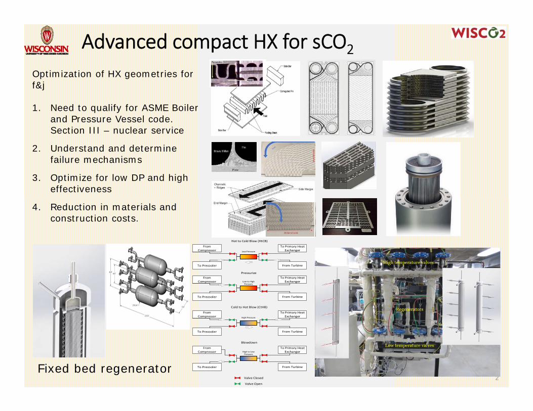
Optimization of HX geometries for f&j
1. Need to qualify for ASME Boiler and Pressure Vessel code. Section III – nuclear service
2. Understand and determine failure mechanisms
3. Optimize for low DP and high effectiveness
4. Reduction in materials and construction costs.
Fixed bed regenerator
From Compressor
To Precooler From Turbine
To Primary Heat ExchangerLow Pressure
Hot to Cold Blow (HtCB)
Pressurize
Cold to Hot Blow (CtHB)
Blowdown
Valve Closed
Valve Open
From Compressor
To Precooler From Turbine
To Primary Heat ExchangerLow to High
Pressure
From Compressor
To Precooler From Turbine
To Primary Heat ExchangerHigh Pressure
From Compressor
To Precooler From Turbine
To Primary Heat ExchangerHigh to Low
Pressure
Section VIII -vs- Section III
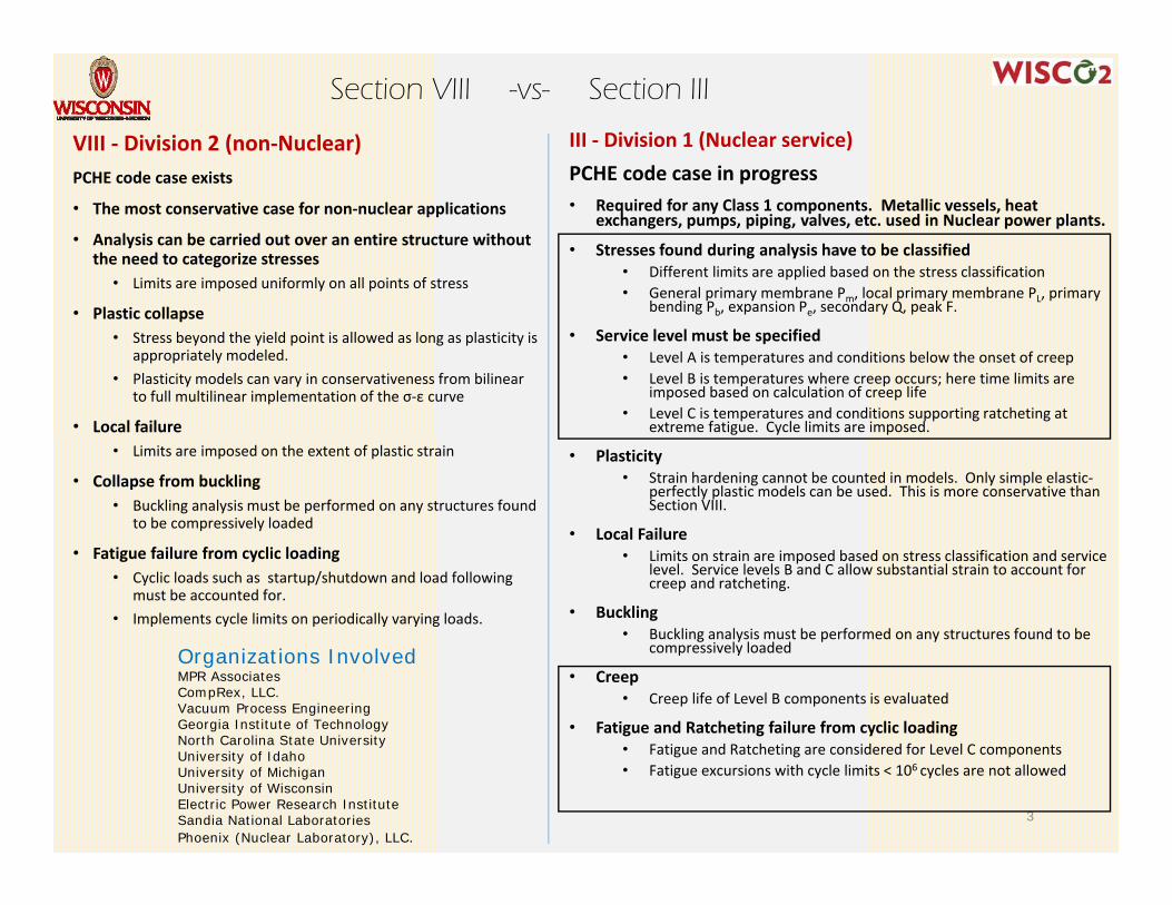
VIII ‐ Division 2 (non‐Nuclear)PCHE code case exists
• The most conservative case for non‐nuclear applications
• Analysis can be carried out over an entire structure without the need to categorize stresses
• Limits are imposed uniformly on all points of stress
• Plastic collapse• Stress beyond the yield point is allowed as long as plasticity is
appropriately modeled. • Plasticity models can vary in conservativeness from bilinear
to full multilinear implementation of the σ‐ε curve
• Local failure• Limits are imposed on the extent of plastic strain
• Collapse from buckling• Buckling analysis must be performed on any structures found
to be compressively loaded
• Fatigue failure from cyclic loading• Cyclic loads such as startup/shutdown and load following
must be accounted for.• Implements cycle limits on periodically varying loads.
3
III ‐ Division 1 (Nuclear service)PCHE code case in progress• Required for any Class 1 components. Metallic vessels, heat
exchangers, pumps, piping, valves, etc. used in Nuclear power plants.
• Stresses found during analysis have to be classified• Different limits are applied based on the stress classification• General primary membrane Pm, local primary membrane PL, primary
bending Pb, expansion Pe, secondary Q, peak F.
• Service level must be specified• Level A is temperatures and conditions below the onset of creep • Level B is temperatures where creep occurs; here time limits are
imposed based on calculation of creep life• Level C is temperatures and conditions supporting ratcheting at
extreme fatigue. Cycle limits are imposed.
• Plasticity• Strain hardening cannot be counted in models. Only simple elastic‐
perfectly plastic models can be used. This is more conservative than Section VIII.
• Local Failure• Limits on strain are imposed based on stress classification and service
level. Service levels B and C allow substantial strain to account for creep and ratcheting.
• Buckling• Buckling analysis must be performed on any structures found to be
compressively loaded
• Creep• Creep life of Level B components is evaluated
• Fatigue and Ratcheting failure from cyclic loading• Fatigue and Ratcheting are considered for Level C components• Fatigue excursions with cycle limits < 106 cycles are not allowed
Organizations InvolvedMPR Associates CompRex, LLC.Vacuum Process EngineeringGeorgia Institute of TechnologyNorth Carolina State UniversityUniversity of IdahoUniversity of MichiganUniversity of WisconsinElectric Power Research InstituteSandia National LaboratoriesPhoenix (Nuclear Laboratory), LLC.
Code & Commercialization gaps
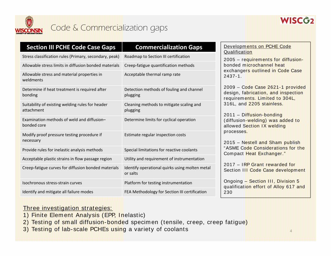
Section III PCHE Code Case Gaps Commercialization GapsStress classification rules (Primary, secondary, peak) Roadmap to Section III certification
Allowable stress limits in diffusion bonded materials Creep‐fatigue quantification methods
Allowable stress and material properties in weldments
Acceptable thermal ramp rate
Determine if heat treatment is required after bonding
Detection methods of fouling and channel plugging
Suitability of existing welding rules for header attachment
Cleaning methods to mitigate scaling and plugging
Examination methods of weld and diffusion–bonded core
Determine limits for cyclical operation
Modify proof pressure testing procedure if necessary
Estimate regular inspection costs
Provide rules for inelastic analysis methods Special limitations for reactive coolants
Acceptable plastic strains in flow passage region Utility and requirement of instrumentation
Creep‐fatigue curves for diffusion bonded materials Identify operational quirks using molten metal or salts
Isochronous stress‐strain curves Platform for testing instrumentation
Identify and mitigate all failure modes FEA Methodology for Section III certification
4
Three investigation strategies:1) Finite Element Analysis (EPP, Inelastic)2) Testing of small diffusion-bonded specimen (tensile, creep, creep fatigue)3) Testing of lab-scale PCHEs using a variety of coolants
Developments on PCHE Code Qualification 2005 – requirements for diffusion-bonded microchannel heat exchangers outlined in Code Case 2437-1.
2009 – Code Case 2621-1 provided design, fabrication, and inspection requirements. Limited to 304L, 316L, and 2205 stainless.
2011 – Diffusion-bonding (diffusion-welding) was added to allowed Section IX welding processes.
2015 – Nestell and Sham publish “ASME Code Considerations for the Compact Heat Exchanger.”
2017 – IRP Grant rewarded for Section III Code Case development
Ongoing – Section III, Division 5 qualification effort of Alloy 617 and 230
Printed-Circuit Heat Exchanger (PCHE)
5
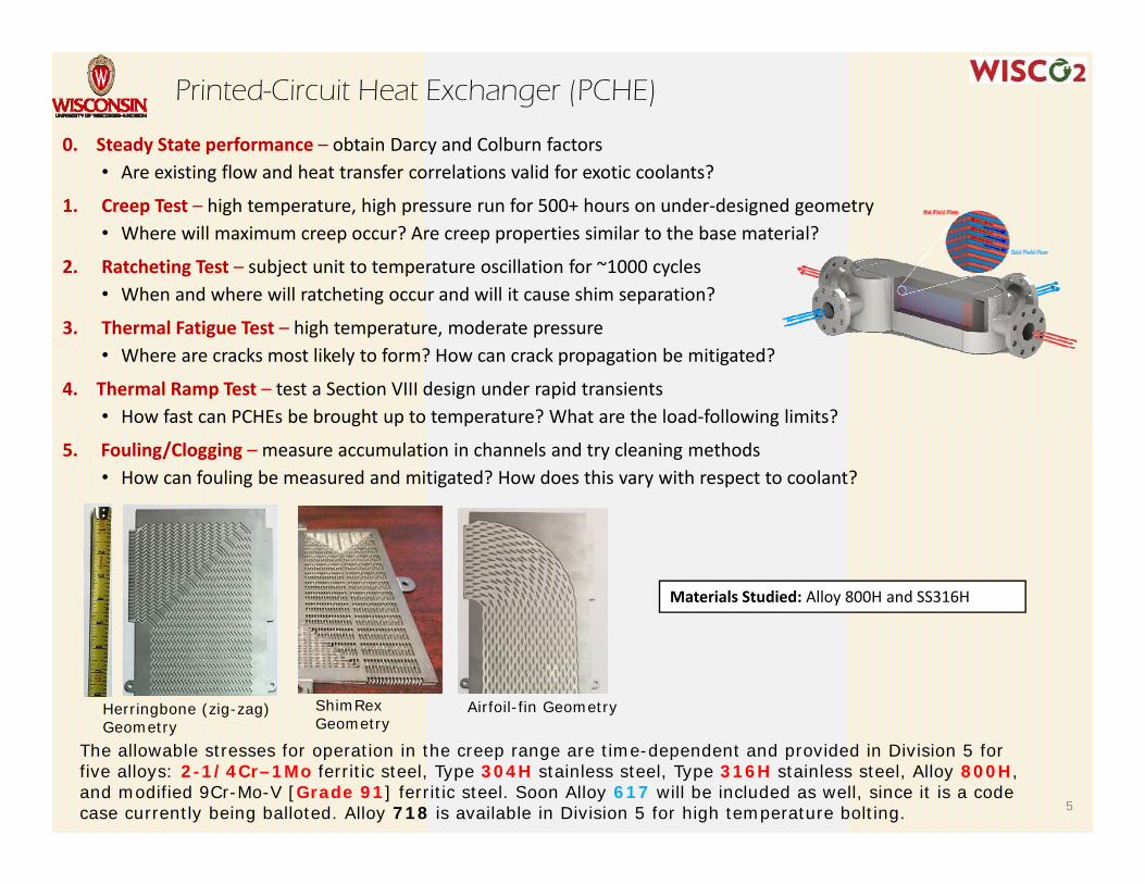
ShimRex Geometry
Herringbone (zig-zag) Geometry
Materials Studied: Alloy 800H and SS316H
Airfoil-fin Geometry
The allowable stresses for operation in the creep range are time-dependent and provided in Division 5 for five alloys: 2-1/4Cr–1Mo ferritic steel, Type 304H stainless steel, Type 316H stainless steel, Alloy 800H, and modified 9Cr-Mo-V [Grade 91] ferritic steel. Soon Alloy 617 will be included as well, since it is a code case currently being balloted. Alloy 718 is available in Division 5 for high temperature bolting.
0. Steady State performance – obtain Darcy and Colburn factors• Are existing flow and heat transfer correlations valid for exotic coolants?
1. Creep Test – high temperature, high pressure run for 500+ hours on under‐designed geometry• Where will maximum creep occur? Are creep properties similar to the base material?
2. Ratcheting Test – subject unit to temperature oscillation for ~1000 cycles• When and where will ratcheting occur and will it cause shim separation?
3. Thermal Fatigue Test – high temperature, moderate pressure• Where are cracks most likely to form? How can crack propagation be mitigated?
4. Thermal Ramp Test – test a Section VIII design under rapid transients• How fast can PCHEs be brought up to temperature? What are the load‐following limits?
5. Fouling/Clogging – measure accumulation in channels and try cleaning methods• How can fouling be measured and mitigated? How does this vary with respect to coolant?
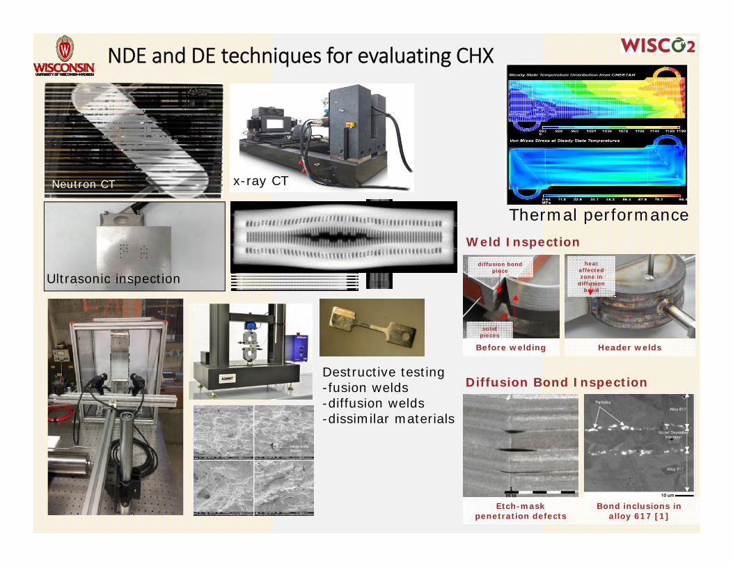
Weld Inspection
Diffusion Bond Inspection
Etch-mask penetration defects
Bond inclusions in alloy 617 [1]
1 mm
Header weldsBefore welding
diffusion bond piece
solid pieces
heat affected zone in
diffusion bond
NDE and DE techniques for evaluating CHX
Ultrasonic inspection
x-ray CT
Thermal performance
Neutron CT
Destructive testing-fusion welds-diffusion welds-dissimilar materials
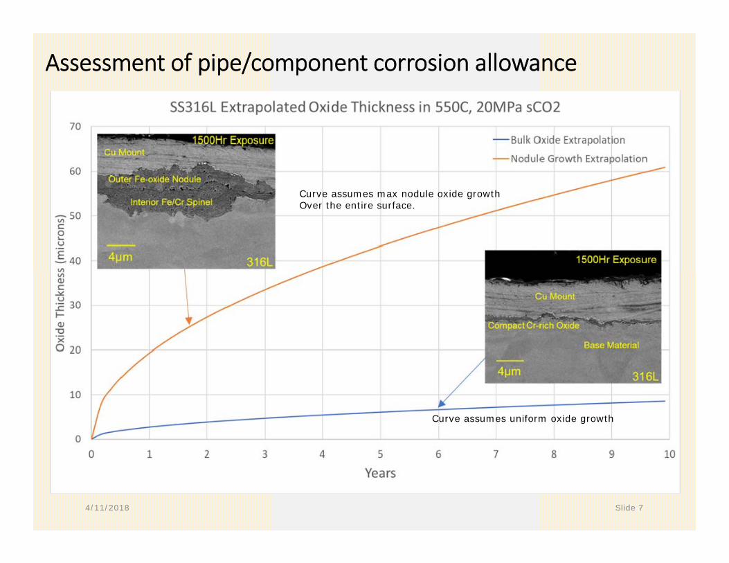
Assessment of pipe/component corrosion allowance
4/11/2018 Slide 7
Curve assumes uniform oxide growth
Curve assumes max nodule oxide growthOver the entire surface.
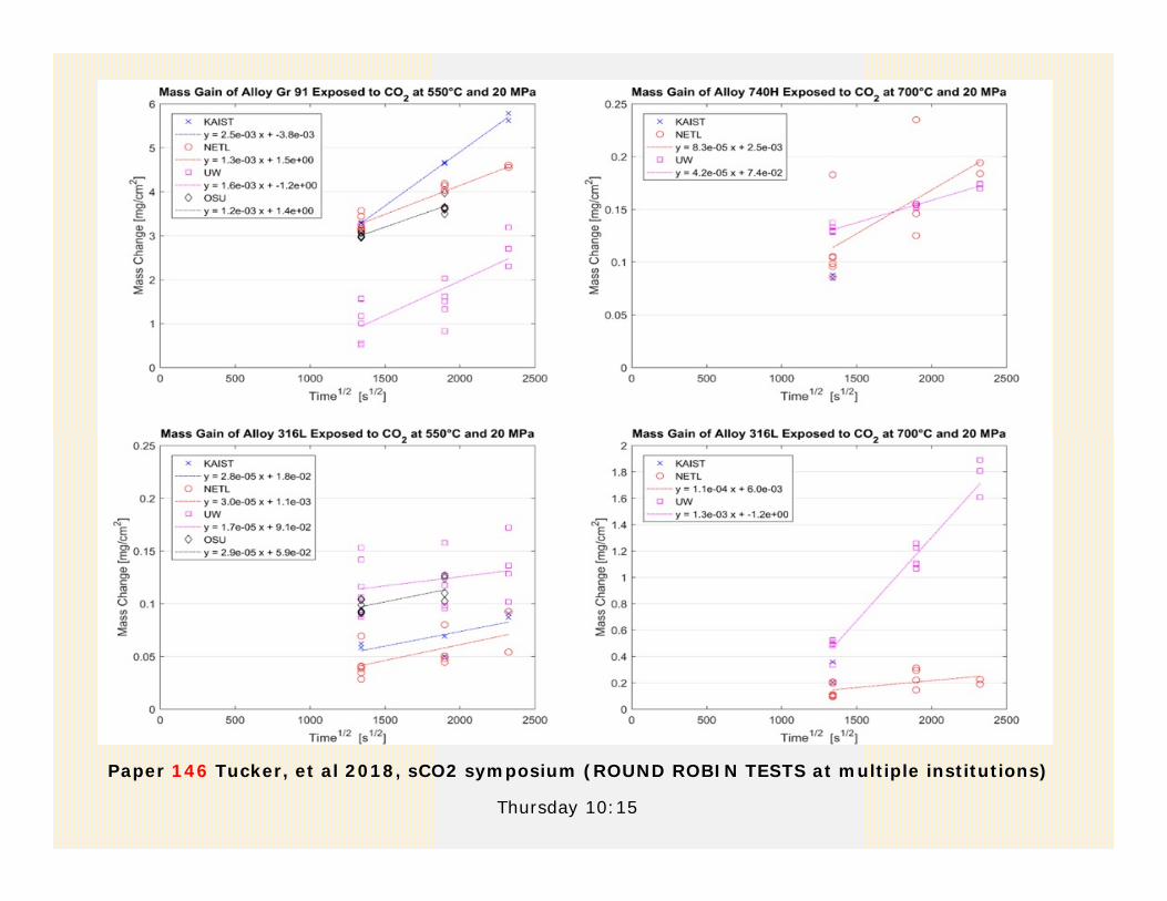
Paper 146 Tucker, et al 2018, sCO2 symposium (ROUND ROBIN TESTS at multiple institutions)
Thursday 10:15
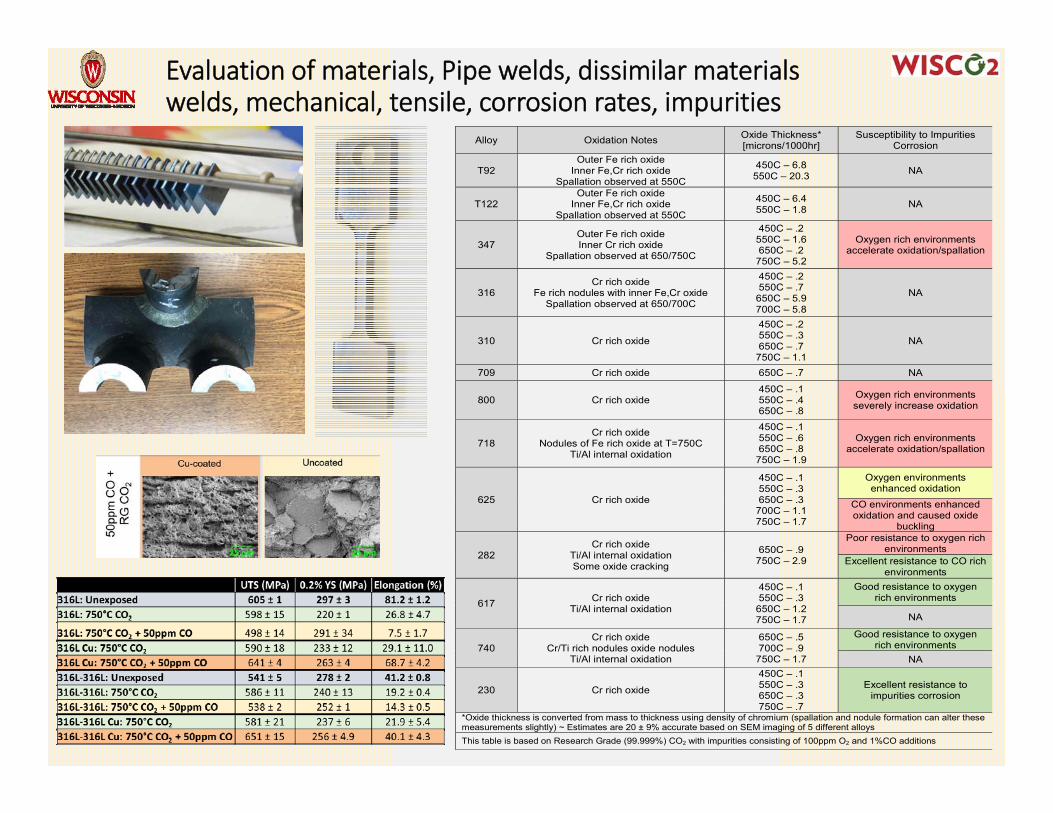
Evaluation of materials, Pipe welds, dissimilar materials welds, mechanical, tensile, corrosion rates, impurities
Alloy Oxidation Notes Oxide Thickness* [microns/1000hr]
Susceptibility to Impurities Corrosion
T92 Outer Fe rich oxide
Inner Fe,Cr rich oxide Spallation observed at 550C
450C – 6.8 550C – 20.3 NA
T122 Outer Fe rich oxide
Inner Fe,Cr rich oxide Spallation observed at 550C
450C – 6.4 550C – 1.8 NA
347 Outer Fe rich oxide Inner Cr rich oxide
Spallation observed at 650/750C
450C – .2 550C – 1.6 650C – .2
750C – 5.2
Oxygen rich environments accelerate oxidation/spallation
316 Cr rich oxide
Fe rich nodules with inner Fe,Cr oxide Spallation observed at 650/700C
450C – .2 550C – .7
650C – 5.9 700C – 5.8
NA
310 Cr rich oxide
450C – .2 550C – .3 650C – .7
750C – 1.1
NA
709 Cr rich oxide 650C – .7 NA
800 Cr rich oxide 450C – .1 550C – .4 650C – .8
Oxygen rich environments severely increase oxidation
718 Cr rich oxide
Nodules of Fe rich oxide at T=750C Ti/Al internal oxidation
450C – .1 550C – .6 650C – .8
750C – 1.9
Oxygen rich environments accelerate oxidation/spallation
625 Cr rich oxide
450C – .1 550C – .3 650C – .3
700C – 1.1 750C – 1.7
Oxygen environments enhanced oxidation
CO environments enhanced oxidation and caused oxide
buckling
282 Cr rich oxide
Ti/Al internal oxidation Some oxide cracking
650C – .9 750C – 2.9
Poor resistance to oxygen rich environments
Excellent resistance to CO rich environments
617 Cr rich oxide Ti/Al internal oxidation
450C – .1 550C – .3
650C – 1.2 750C – 1.7
Good resistance to oxygen rich environments
NA
740 Cr rich oxide
Cr/Ti rich nodules oxide nodules Ti/Al internal oxidation
650C – .5 700C – .9
750C – 1.7
Good resistance to oxygen rich environments
NA
230 Cr rich oxide
450C – .1 550C – .3 650C – .3 750C – .7
Excellent resistance to impurities corrosion
*Oxide thickness is converted from mass to thickness using density of chromium (spallation and nodule formation can alter these measurements slightly) ~ Estimates are 20 ± 9% accurate based on SEM imaging of 5 different alloysThis table is based on Research Grade (99.999%) CO2 with impurities consisting of 100ppm O2 and 1%CO additions
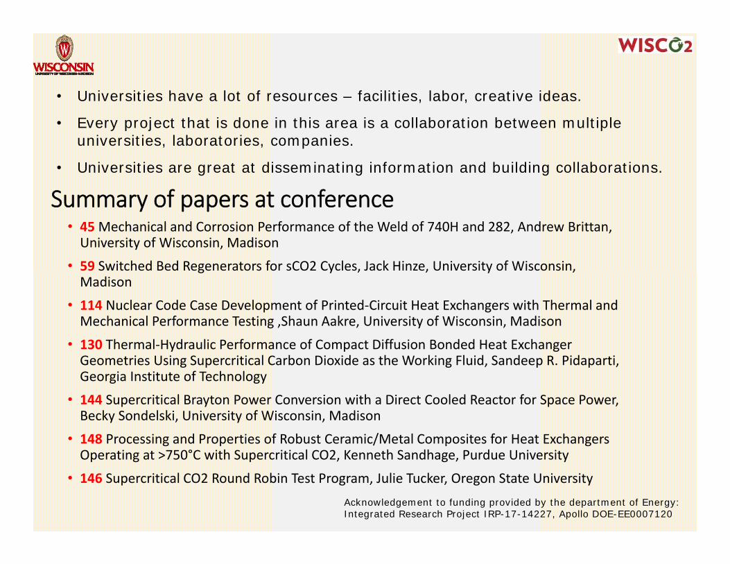
Summary of papers at conference• 45Mechanical and Corrosion Performance of the Weld of 740H and 282, Andrew Brittan, University of Wisconsin, Madison
• 59 Switched Bed Regenerators for sCO2 Cycles, Jack Hinze, University of Wisconsin, Madison
• 114 Nuclear Code Case Development of Printed‐Circuit Heat Exchangers with Thermal and Mechanical Performance Testing ,Shaun Aakre, University of Wisconsin, Madison
• 130 Thermal‐Hydraulic Performance of Compact Diffusion Bonded Heat Exchanger Geometries Using Supercritical Carbon Dioxide as the Working Fluid, Sandeep R. Pidaparti, Georgia Institute of Technology
• 144 Supercritical Brayton Power Conversion with a Direct Cooled Reactor for Space Power, Becky Sondelski, University of Wisconsin, Madison
• 148 Processing and Properties of Robust Ceramic/Metal Composites for Heat Exchangers Operating at >750°C with Supercritical CO2, Kenneth Sandhage, Purdue University
• 146 Supercritical CO2 Round Robin Test Program, Julie Tucker, Oregon State University
• Universities have a lot of resources – facilities, labor, creative ideas.
• Every project that is done in this area is a collaboration between multiple universities, laboratories, companies.
• Universities are great at disseminating information and building collaborations.
Acknowledgement to funding provided by the department of Energy:Integrated Research Project IRP-17-14227, Apollo DOE-EE0007120