healthy high-rise english
TRANSCRIPT
ealthy High-riseHA Guide toInnovation in the Design andConstructionof High-RiseResidentialBuildings

Canada Mortgage and Housing Corporation supports theGovernment of Canada policy on access to information forpeople with disabilities. If you wish to obtain this publication in alternative formats, call 1 800 668-2642.
CMHC—Home to Canadians
Canada Mortgage and Housing Corporation (CMHC) is the Government ofCanada’s national housing agency.We help Canadians gain access to a widechoice of quality, affordable homes.
Our mortgage loan insurance program has helped many Canadians realize theirdream of owning a home.We provide financial assistance to help Canadians mostin need to gain access to safe, affordable housing.Through our research, weencourage innovation in housing design and technology, community planning,housing choice and finance.We also work in partnership with industry and otherTeam Canada members to sell Canadian products and expertise in foreign markets, thereby creating jobs for Canadians here at home.
We offer a wide variety of information products to consumers and the housingindustry to help them make informed purchasing and business decisions.WithCanada’s most comprehensive selection of information about housing andhomes, we are Canada’s largest publisher of housing information.
In everything that we do, we are helping to improve the quality of life forCanadians in communities across this country.We are helping Canadians live in safe, secure homes. CMHC is home to Canadians.
Canadians can easily access our information through retail outlets and CMHC’sregional offices.
You can also reach us by phone at 1 800 668-2642 (outside Canada call (613) 748-2003)By fax at 1 800 245-9274 (outside Canada (613) 748-2016)
To reach us online, visit our home page at www.cmhc-schl.gc.ca
Healthy High-RiseA Guide to Innovation in the Design and
Construction of High-Rise Residential Buildings
Canada Mortgage and Housing Corporation
Prepared by:The Sheltair Group
Société Logique Inc.Paul Kernan, architect
An update of the “IDEAS Challenge Better Buildings -A Guide to Innovation in the Design and Construction
of High-Rise Residential Buildings”
CMHC offers a wide range of housing-related information. For details, call 1 800 668-2642or visit our home page at www.cmhc-schl.gc.ca
Cette publication est aussi disponible en français sous le titre: Guide de conception destours d'habitation saines, 62806

The information contained in this publication represents current research results available toCMHC, and has been reviewed by a wide spectrum of experts in the housing industry. Readersare advised to evaluate the information, materials and techniques cautiously for themselves andto consult appropriate professional resources to determine whether information, materials andtechniques are suitable in their case.The drawings and text are intended as general practiceguides only. Project and site-specific factors of climate, cost, aesthetics, and so on must betaken into consideration.Any photographs in this book are for illustration purposes only andmay not necessarily represent currently accepted standards
© 2001 Canada Mortgage and Housing Corporation All rights reserved. No portion of this book may be reproduced, stored in a retrieval systemor transmitted in any form or by any means, mechanical, electronic, photocopying, recording orotherwise without the prior written permission of Canada Mortgage and HousingCorporation.Without limiting the generality of the foregoing, no portion of this book may betranslated from English into any other language without the prior written permission ofCanada Mortgage and Housing Corporation.
FlexHousing™ and Healthy Housing™ are trademarks of Canada Mortgage and HousingCorporation.
Printed in CanadaProduced by CMHC

Page i
INTRODUCTION . . . . . . . . . . . . . . . . . . . . . . . . . . . . . . . . . . . . . . . . . . . . . . . . . . . . . . . . . 1
ENHANCING ENVELOPE DESIGN . . . . . . . . . . . . . . . . . . . . . . . . . . . . . . . . . . . . . . . . . . 7
ENHANCING ENERGY PERFORMANCE. . . . . . . . . . . . . . . . . . . . . . . . . . . . . . . . . . . . 29
ENHANCING INDOOR AIR QUALITY . . . . . . . . . . . . . . . . . . . . . . . . . . . . . . . . . . . . . . 57
ENHANCING ENVIRONMENTAL PERFORMANCE. . . . . . . . . . . . . . . . . . . . . . . . . . . 71
ENHANCING ACCESSIBILITY . . . . . . . . . . . . . . . . . . . . . . . . . . . . . . . . . . . . . . . . . . . 101
GREEN INFRASTRUCTURE. . . . . . . . . . . . . . . . . . . . . . . . . . . . . . . . . . . . . . . . . . . . . . 109
TABLE OF CONTENTS


Page 1
High-rise residential buildings play an importantrole in expanding Canadians’ housing choices.The buildings provide housing choices rangingfrom affordable housing for low income rentersthrough to luxury units in some of Canada’s mostprestigious locations. It is estimated that 20% ofCanadians live in multi-unit residential buildings.
While the benefits of these housing choices aregenerally considerable - proximity to services,public transportation, efficient use of land andinfrastructure - the quality of the housing unitshas not reflected recent technological advances.
A list of common inadequacies include:
• water penetration and air leakage through thebuilding envelope resulting in structural andother damage, high energy cost and occupantdiscomfort,
• inadequate thermal envelope performance andthermal bridging resulting in occupantdiscomfort and high energy bills,
• HVAC systems influenced by strong buildingstack effects and wind pressures which resultin poor comfort levels and poor indoor airquality,
• insensitive use of land which impacts onstormwater flow,
• high domestic water consumption,• occupant dissatisfaction relating to noise
levels,• a lack of accessibility to people with
disabilities.
These problems are not solely those of the buildingoccupants. Increasingly across the country, the costof remedial repairs and replacement ofdeteriorating components of the building are beinglegally passed back to the developer.
In all too many instances, repair costs for newbuildings are being assumed by WarrantyPrograms, thus depleting their reserves. InOntario alone, warranty claim payouts for high-rise buildings are approaching $20 millionannually.
Researchers, architects and engineers in the fieldagree that better performing buildings can beconstructed. They acknowledge that improvingperformance will require changes in the designand construction process, requiring morecomprehensive and improved building detailing,enhanced quality control and buildingcommissioning processes, improved buildingoperation and maintenance procedures, andunderstanding the building construction andoperation as a whole.
Over the last several years, building scientists,researchers and practitioners with considerableexpertise have invested substantial resources andenergy in identifying the causes of typicalproblems in high-rise residential buildings, and in developing improved design and constructionprocedures that could significantly reduce defectsand improve building performance.
An improved understanding of all facets of high-rise design and construction is being developedrelating to virtually every aspect of high-risebuildings. Upgraded parking garages, enhancedenvelope durability through rainscreen and airbarrier design, improvements to the buildingthermal envelope, better heating, cooling andmechanical ventilation systems, measures toimprove the accessibility and functioning ofbuildings, and measures for improving theenvironmental performance of these buildings and the inter relationship between these systemshave all been the subject of recent investigationby government and housing agencies.
INTRODUCTION
THE NEED FOR CHANGE
Page 2
Healthy High-Rise
Canada’s building design and research communityhas historically been at the forefront of innovationin the Canadian construction industry, maintainingour reputation for providing some of the besthousing in the world. Until recently, much of theinnovation was concentrated on the low-risehousing stock where we are acknowledged asworld leaders in the provision of energy efficient,environmentally-responsive housing. It remainsfor the high-rise design and building industry toassume a similar leadership role.
This document is designed to reflect the innovationthat can lead to the design and construction ofbetter performing buildings. It provides:
• an overview of many of the problemsaffecting high-rise buildings which resultfrom conventional practices,
• insight into an improved understanding of the building science principles, and
• design considerations for improving buildingperformance in a variety of areas.
This document is intended to present alternativeways of thinking about design principles for high-rise buildings, to provide some differentapproaches to design, construction,commissioning and operations and maintenance.In many cases, it presents the need for a moreholistic and integrated approach to the design andconstruction of a high-rise residential building.This type of integration is displayed in the“Related Topics” table at the beginning of eachsub-section. Issues related to retrofit opportunitiesand regional differences are also discussed whenthey apply.
Opportunities are also discussed for improvingthe integration of high-rise residential buildingswith the surrounding urban infrastructure,including on-site systems for energy and watersupply, transportation and waste management.
Finally, each section includes “Sources ofInformation” to recent research and developmentstudies. The industry is encouraged to follow-upon these reports that reflect some of the best andmost current information on high-rise buildings.
As innovative practices are adopted, implementedand monitored in high-rise buildings, ourknowledge and understanding will be greatlyenhanced. Readers are encouraged to share theirexperiences with CMHC.
Page 3
Introduction
THE PROCESS
To a large degree, high-rise buildings acrossCanada should be capable of better performance.Opportunities exist to correct specific buildingdefects and deficiencies. But, as one analyses theproblems, the causes often appear in the designand construction processes.
Those involved in the various aspects of a high-rise project often perform their own role inisolation from others. When problems arise, thereis invariably “finger pointing” at the role ofothers in the process - architects suggesting thatworkmanship is poor, contractors stating thatdetails were not buildable, engineers suggestingthe developer needs to provide more funds forsite inspections, and so on. The benefits of a teamapproach are seldom witnessed.
Only through a review and rethinking of theprocess will many of the following problems beresolved. Through the use of an integrated designprocess, where all disciplines collaborate todevelop the building as a system of mutuallybeneficial components, improvements indurability, efficiency, comfort and aesthetics canbe achieved without cost surcharges.
Design DeficienciesResearchers have been able to draw a directcorrelation between the limitations of projectdesigns and problems in high-rise buildings. Theysingle out inadequate details and incorrect details(reflecting a poor understanding of buildingsciences) as common problems. And the rationalefor specific details is usually not effectivelycommunicated to the field.
Construction DeficienciesEven where plans and specifications are excellent,problems can arise. Specified materials arefrequently substituted for those which are notcompatible in their place of application.Manufacturers’ installation requirements can beshort-circuited by trades. Training of sub-
contractors is ad hoc and project quality controlmeasures are seldom sufficient. From theconceptual stage, a more active role of an integratedproject team in ensuring that construction meets the project requirements is essential to improvingbuilding performance. However, this can only beachieved if the owner/developer commits to theprocess in advance of this step.
Commissioning and TestingNon-existent or inadequate commissioning andtesting protocols fail to detect constructiondefects, resulting in increased costs for buildingowners and operators.
All too often, problems are identified at a latestage in the construction process, or after buildingis occupied requiring costly remedial work.Mock-up testing of typical sample assemblies isan essential tool in ensuring that the project willoperate as intended. More often than not, the costof testing pays for itself within the constructionperiod as well as saving costs thereafter.
Operations and MaintenanceFrequently, a building is “turned over” withoutany formal communication about the operatingand maintenance requirements. The project teammust assume responsibility for communicatingtheir design assumptions, operational expectations,and maintenance requirements to the propertymanager. Operations manuals must be prepared,and staff must be trained to perform regularmaintenance to minimize more costly remedialand repair work and to ensure efficient functioningof all building systems. Documentation must alsobe prepared for tenants/owners as well as walk-through demonstrations.
Most of the problems that occur in high-riseresidential buildings are the result of interplaybetween the movement of air, moisture and heat.An improved understanding by designers of theforces acting in a high-rise building is essential to better performance.
BUILDING FAILURES
Page 4
Healthy High-Rise
THE PRINCIPLES
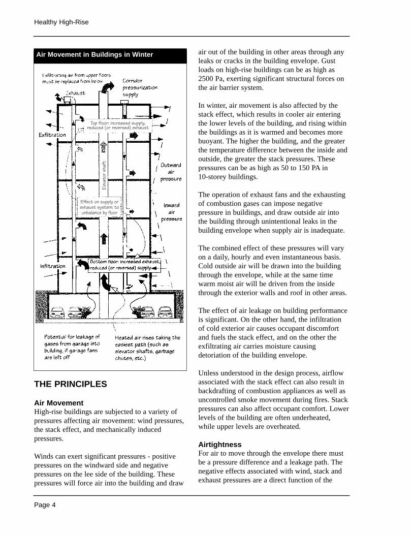
Air MovementHigh-rise buildings are subjected to a variety ofpressures affecting air movement: wind pressures,the stack effect, and mechanically inducedpressures.
Winds can exert significant pressures - positivepressures on the windward side and negativepressures on the lee side of the building. Thesepressures will force air into the building and draw
air out of the building in other areas through anyleaks or cracks in the building envelope. Gustloads on high-rise buildings can be as high as2500 Pa, exerting significant structural forces onthe air barrier system.
In winter, air movement is also affected by thestack effect, which results in cooler air enteringthe lower levels of the building, and rising withinthe buildings as it is warmed and becomes morebuoyant. The higher the building, and the greaterthe temperature difference between the inside andoutside, the greater the stack pressures. Thesepressures can be as high as 50 to 150 PA in 10-storey buildings.
The operation of exhaust fans and the exhaustingof combustion gases can impose negativepressure in buildings, and draw outside air intothe building through unintentional leaks in thebuilding envelope when supply air is inadequate.
The combined effect of these pressures will varyon a daily, hourly and even instantaneous basis.Cold outside air will be drawn into the buildingthrough the envelope, while at the same timewarm moist air will be driven from the insidethrough the exterior walls and roof in other areas.
The effect of air leakage on building performanceis significant. On the other hand, the infiltrationof cold exterior air causes occupant discomfortand fuels the stack effect, and on the other theexfiltrating air carries moisture causingdetoriation of the building envelope.
Unless understood in the design process, airflowassociated with the stack effect can also result inbackdrafting of combustion appliances as well asuncontrolled smoke movement during fires. Stackpressures can also affect occupant comfort. Lowerlevels of the building are often underheated,while upper levels are overheated.
AirtightnessFor air to move through the envelope there mustbe a pressure difference and a leakage path. Thenegative effects associated with wind, stack andexhaust pressures are a direct function of the
Air Movement in Buildings in Winter
Top floor: increased supply,reduced (or reversed) exhaust
Effect on supply orexhaust system: to unbalance by floor
Elev
ator
sha
ft
Page 5
Introduction
airtightness of the building envelope. If thebuilding were completely airtight, there would be no airflow. Pragmatically this is not possible.But significantly increasing the airtightness of abuilding is achievable - and is the cornerstone ofenhancing envelope durability, occupant comfort,and HVAC system performance.
Tightening the building envelope will effectivelycounter the movement of air caused by the stackeffect in buildings. By reducing leakage paths,uncontrolled air movement will be greatlyreduced, allowing for improved comfort.
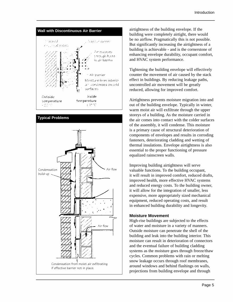
Airtightness prevents moisture migration into andout of the building envelope. Typically in winter,warm moist air will exfiltrate through the upperstoreys of a building. As the moisture carried inthe air comes into contact with the colder surfacesof the assembly, it will condense. This moisture is a primary cause of structural deterioration ofcomponents of envelopes and results in corrodingfasteners, deteriorating cladding and wetting ofthermal insulations. Envelope airtightness is alsoessential to the proper functioning of pressureequalized rainscreen walls.
Improving building airtightness will servevaluable functions. To the building occupant, it will result in improved comfort, reduced drafts,improved health, more effective HVAC systemsand reduced energy costs. To the building owner,it will allow for the integration of smaller, lessexpensive, more appropriately sized mechanicalequipment, reduced operating costs, and result in enhanced building durability and longevity.
Moisture MovementHigh-rise buildings are subjected to the effects of water and moisture in a variety of manners.Outside moisture can penetrate the shell of thebuilding and leak into the building interior. Thismoisture can result in deterioration of connectorsand the eventual failure of building claddingsystems as the moisture goes through freeze/thawcycles. Common problems with rain or meltingsnow leakage occurs through roof membranes,around windows and behind flashings on walls,projections from building envelope and through
Wall with Discontinuous Air Barrier
Typical Problems
Air flow
Air flow
Condensationbuild-up
Condensation from moist air exfiltratingif effective barrier not in place.

Page 6
Healthy High-Rise
cracks in foundation walls and parking garageroofs.
A more invisible force is the movement of watervapour through the building envelope byexfiltration (and to a lesser extent by vapourdiffusion). This vapour will condense within theenvelope as it comes into contact with coolersurfaces. This moisture migration commonlyresults in efflorescence, spalling, delamination offacing materials and other structural damage. Themovement of water vapour can also cause moldand rot within walls which is a health, aesthetic,and eventually a structural concern.
Key control mechanisms to ensure that water andmoisture damage in high-rise buildings isminimized will include:
• improved detailing and construction of wallsand roof membranes (particularly aroundpenetrations and at parapets),
• shedding water away from building envelope,• the use of pressure equalized rainscreen wall
systems,• improved air leakage control,• better detailing and construction and water
sealing of building foundation walls andgarage and terrace roofs,
• particular attention to detailing of jointsbetween materials.
Sources of Information
• Construction Problems in Multi-FamilyResidential Buildings: A Documentation andEvaluation, CMHC, 1991.
• Field Investigation Survey Summary Reportof Airtightness, Air Movement and Indoor AirQuality in High-Rise Apartment Buildings inFive Canadian Regions, CMHC, 1993.
• Controlling Stack Pressure in High-RiseBuildings by Compartmenting the Building,CMHC, 1996.
Page 7
IN THIS SECTION
Air Barriers• continuity• windows• structural support• impermeability to air flow• durability• quality assurance
Wetting of Building Envelopes
Pressure-Equalized Rainscreen• air barrier system• sealed compartments• venting• assymetrical venting• quality control
Exterior Insulation and Finish Systems (EIFS)• rain penetration at joints• interstital condensation• cracking of the lamina
Parking Garages• positive drainage• reduced cracking• elevated joints• surface protection
Low Slope Roofing Systems• seams• membrane moisture• ballast• standing water• green roofs
Regional Differences
The building envelope consists of the materials,assemblies and components that separate the interiorof a building from the exterior. It includes suchelements as walls, windows and doors, roofs, floorsand foundations. The function of these elements isto enclose space in such a way that appropriateinterior environmental conditions (temperature,humidity, air movement, light) can be maintained.
Premature failure of building envelopes occurs in many buildings throughout the country. Thesefailures result in the deterioration of the exteriorfacade of buildings, damage to building interiors,dangerous long-and-short-term structuralsituations, and potential adverse health effects to occupants as a result of exposure to molds.
The knowledge and technology required to design and construct building envelopes that arefree of problems is now available. A more durableenvelope, requiring less maintenance, is the resultof improved understanding of applied buildingsciences, improved detailing on constructiondrawings, and greater attention to detail in theconstruction and commissioning of the buildingenvelope.
By understanding the movement of moisturethrough the building envelope, whether themoisture is from the outside or inside, theprimary cause of premature deterioration can becontrolled. Enhanced envelope performance canbe achieved through greater envelope airtightness,improved water management capabilities, and the application of pressure equalized rainscreensystems and proper water shedding details.
The following section provides an overview of improved approaches to air barrier systems,rainscreen design and commissioningrequirements, water-shedding wall construction,and improved practices relating to the design andconstruction of parking garages and roof systems.In each case, changes to the design, constructionand commissioning of the building envelope arerequired to ensure improved durability.
ENHANCING ENVELOPE DESIGN
Page 8
Healthy High-Rise
Related Topics
Pressure Equalized RainscreenBuilding EnvelopeMechanical VentilationOccupant Comfort - Noise
THE ISSUES
Despite the importance of the air barrier tooverall building performance, air barriertechnologies are just beginning to be understood.Consideration of the air barrier system is oftennot fully integrated into the design process.
An effective air barrier (or more specifically aneffective air barrier system, made up of all thematerials, components and joints functioning to prevent the migration of air) is an essentialcomponent of a well performing buildingenvelope in all climatic regions. The effectivenessof rainscreen designs, improved insulation levels,ventilation and interior comfort are eachdependent on air barrier performance. The airbarrier system will restrict the movement of airthrough the envelope, thereby reducing theprimary transfer mechanism of moisture. Controlof air movement will also improve comfort,envelope durability, and energy efficiency.
Effective air barrier systems require:• thorough detailing and specification of
materials and components,• careful quality control and testing during
construction,• a comprehensive quality assurance process
including commissioning (performanceverification) of installed systems.
The National Building Code requires thatbuildings be designed to provide an effectivebarrier to the infiltration and exfiltration of air.The Code prescribes airtightness requirements forindividual materials used in an air barrier system.In addition there are recommendations for theoverall air barrier system leakage rates.
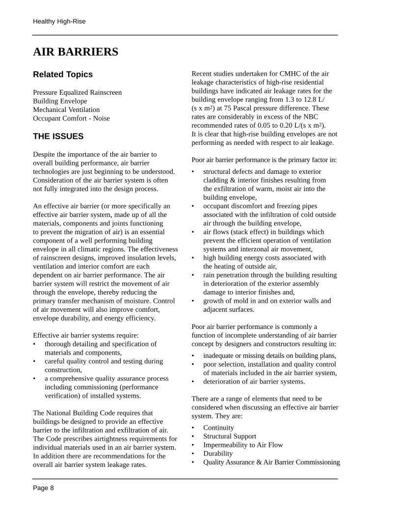
Recent studies undertaken for CMHC of the airleakage characteristics of high-rise residentialbuildings have indicated air leakage rates for thebuilding envelope ranging from 1.3 to 12.8 L/(s x m2) at 75 Pascal pressure difference. Theserates are considerably in excess of the NBCrecommended rates of 0.05 to 0.20 L/(s x m2).It is clear that high-rise building envelopes are notperforming as needed with respect to air leakage.
Poor air barrier performance is the primary factor in:
• structural defects and damage to exteriorcladding & interior finishes resulting from the exfiltration of warm, moist air into thebuilding envelope,
• occupant discomfort and freezing pipesassociated with the infiltration of cold outsideair through the building envelope,
• air flows (stack effect) in buildings whichprevent the efficient operation of ventilationsystems and interzonal air movement,
• high building energy costs associated with the heating of outside air,
• rain penetration through the building resultingin deterioration of the exterior assemblydamage to interior finishes and,
• growth of mold in and on exterior walls andadjacent surfaces.
Poor air barrier performance is commonly afunction of incomplete understanding of air barrierconcept by designers and constructors resulting in:
• inadequate or missing details on building plans,• poor selection, installation and quality control
of materials included in the air barrier system,• deterioration of air barrier systems.
There are a range of elements that need to beconsidered when discussing an effective air barriersystem. They are:
• Continuity• Structural Support• Impermeability to Air Flow• Durability• Quality Assurance & Air Barrier Commissioning
AIR BARRIERS
Page 9
Enhancing Envelope Design
DESIGN CONSIDERATIONS
ContinuityThe air barrier is made up of a variety of materials,components and joints. The air barrier should beviewed as a system typically comprised of sheet ormembrane materials (for example, on walls androof, windows, metal curtain wall panels), andsealant and gasketing materials intended tofunction as joints providing an airtight seal.
Not only must all components of the air barriersystem be correctly selected, designed, andinstalled with airtight and durable connections,but the air barrier system must also be effectivelysealed to all penetrations in the envelopeincluding through windows, ducts, vents,electrical conduits and fixtures.
Detailing of joints and connections must reflectan understanding of material compatibility,ensuring adequate strength, adhesion andelasticity of attachments, to accommodatedifferential component movement and the needfor structural support. All elements of the airbarrier must be designed to perform over theexpected life span of the building or be readilyaccessible to allow repair or replacement withoutdamage to other envelope components.
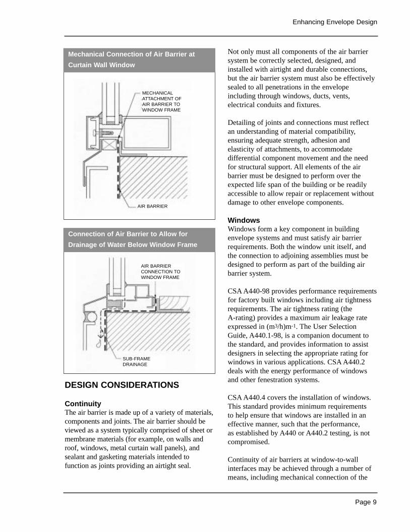
WindowsWindows form a key component in buildingenvelope systems and must satisfy air barrierrequirements. Both the window unit itself, and the connection to adjoining assemblies must bedesigned to perform as part of the building airbarrier system.
CSA A440-98 provides performance requirementsfor factory built windows including air tightnessrequirements. The air tightness rating (the A-rating) provides a maximum air leakage rateexpressed in (m3/h)m-1. The User SelectionGuide, A440.1-98, is a companion document tothe standard, and provides information to assistdesigners in selecting the appropriate rating forwindows in various applications. CSA A440.2deals with the energy performance of windowsand other fenestration systems.
CSA A440.4 covers the installation of windows.This standard provides minimum requirements to help ensure that windows are installed in aneffective manner, such that the performance, as established by A440 or A440.2 testing, is notcompromised.
Continuity of air barriers at window-to-wallinterfaces may be achieved through a number ofmeans, including mechanical connection of the
Mechanical Connection of Air Barrier at
Curtain Wall Window
Connection of Air Barrier to Allow for
Drainage of Water Below Window Frame
MECHANICALATTACHMENT OF AIR BARRIER TO WINDOW FRAME
AIR BARRIER
AIR BARRIERCONNECTION TOWINDOW FRAME
SUB-FRAMEDRAINAGE
Page 10
Healthy High-Rise
wall air barrier to the window, sealants, self-adhesive membranes or urethane foams.
The most appropriate method will depend on thetype of window used and on other performance
characteristics of the window. With some windowtypes, provision for drainage of water from thewindow frame is required. In this case the airbarrier connection must be made in a manner thatwill not impede movement of water to the exterioror to a drainage cavity in the wall assembly.
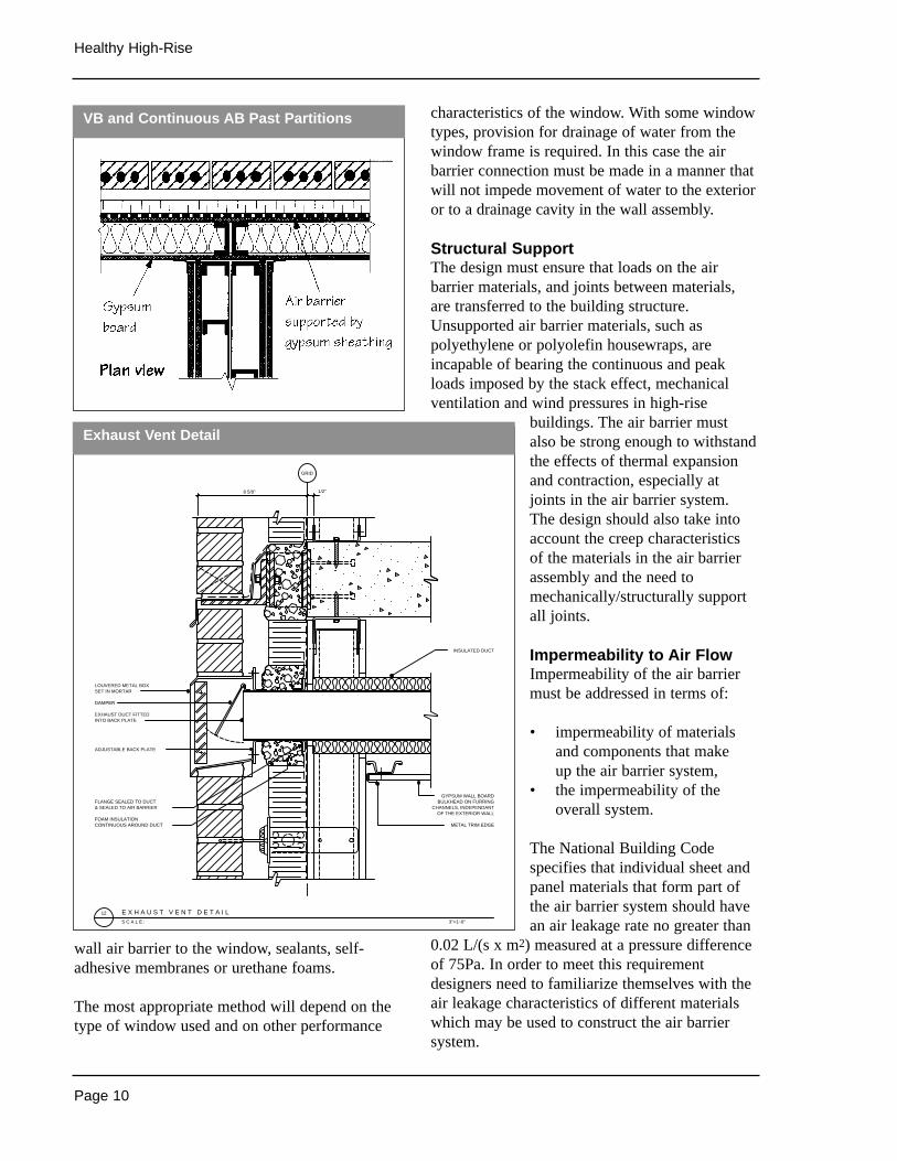
Structural SupportThe design must ensure that loads on the airbarrier materials, and joints between materials,are transferred to the building structure.Unsupported air barrier materials, such aspolyethylene or polyolefin housewraps, areincapable of bearing the continuous and peakloads imposed by the stack effect, mechanicalventilation and wind pressures in high-rise
buildings. The air barrier mustalso be strong enough to withstandthe effects of thermal expansionand contraction, especially atjoints in the air barrier system.The design should also take intoaccount the creep characteristicsof the materials in the air barrierassembly and the need tomechanically/structurally supportall joints.
Impermeability to Air FlowImpermeability of the air barriermust be addressed in terms of:
• impermeability of materialsand components that make up the air barrier system,
• the impermeability of theoverall system.
The National Building Codespecifies that individual sheet andpanel materials that form part ofthe air barrier system should havean air leakage rate no greater than
0.02 L/(s x m2) measured at a pressure differenceof 75Pa. In order to meet this requirementdesigners need to familiarize themselves with theair leakage characteristics of different materialswhich may be used to construct the air barriersystem.
VB and Continuous AB Past Partitions
E X H A U S T V E N T D E T A I L
GRID
DAMPER
SET IN MORTARLOUVERED METAL BOX
INTO BACK PLATE
ADJUSTABLE BACK PLATE
EXHAUST DUCT FITTED
& SEALED TO AIR BARRIERFLANGE SEALED TO DUCT
INSULATED DUCT
GYPSUM WALL BOARDBULKHEAD ON FURRING
CHANNELS, INDEPENDANTOF THE EXTERIOR WALL
METAL TRIM EDGEFOAM INSULATIONCONTINUOUS AROUND DUCT
3"=1'-0"S C A L E :
12
8 5/8" 1/2"
Exhaust Vent Detail
Page 11
Enhancing Envelope Design
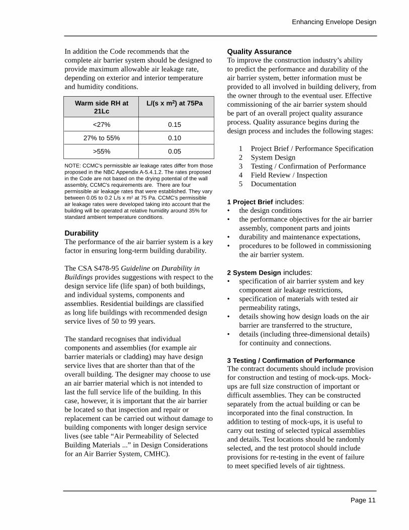
In addition the Code recommends that thecomplete air barrier system should be designed toprovide maximum allowable air leakage rate,depending on exterior and interior temperatureand humidity conditions.
NOTE: CCMC's permissible air leakage rates differ from thoseproposed in the NBC Appendix A-5.4.1.2. The rates proposedin the Code are not based on the drying potential of the wallassembly, CCMC's requirements are. There are fourpermissible air leakage rates that were established. They varybetween 0.05 to 0.2 L/s x m2 at 75 Pa. CCMC's permissibleair leakage rates were developed taking into account that thebuilding will be operated at relative humidity around 35% forstandard ambient temperature conditions.
DurabilityThe performance of the air barrier system is a keyfactor in ensuring long-term building durability.
The CSA S478-95 Guideline on Durability inBuildings provides suggestions with respect to thedesign service life (life span) of both buildings,and individual systems, components andassemblies. Residential buildings are classified as long life buildings with recommended designservice lives of 50 to 99 years.
The standard recognises that individualcomponents and assemblies (for example airbarrier materials or cladding) may have designservice lives that are shorter than that of theoverall building. The designer may choose to usean air barrier material which is not intended tolast the full service life of the building. In thiscase, however, it is important that the air barrierbe located so that inspection and repair orreplacement can be carried out without damage tobuilding components with longer design servicelives (see table “Air Permeability of SelectedBuilding Materials ...” in Design Considerationsfor an Air Barrier System, CMHC).
Quality Assurance To improve the construction industry’s ability to predict the performance and durability of theair barrier system, better information must beprovided to all involved in building delivery, fromthe owner through to the eventual user. Effectivecommissioning of the air barrier system should be part of an overall project quality assuranceprocess. Quality assurance begins during thedesign process and includes the following stages:
1 Project Brief / Performance Specification2 System Design3 Testing / Confirmation of Performance4 Field Review / Inspection5 Documentation
1 Project Brief includes:• the design conditions• the performance objectives for the air barrier
assembly, component parts and joints• durability and maintenance expectations,• procedures to be followed in commissioning
the air barrier system.
2 System Design includes:• specification of air barrier system and key
component air leakage restrictions,• specification of materials with tested air
permeability ratings,• details showing how design loads on the air
barrier are transferred to the structure,• details (including three-dimensional details)
for continuity and connections.
3 Testing / Confirmation of PerformanceThe contract documents should include provisionfor construction and testing of mock-ups. Mock-ups are full size construction of important ordifficult assemblies. They can be constructedseparately from the actual building or can beincorporated into the final construction. Inaddition to testing of mock-ups, it is useful tocarry out testing of selected typical assembliesand details. Test locations should be randomlyselected, and the test protocol should includeprovisions for re-testing in the event of failure to meet specified levels of air tightness.
Warm side RH at L/(s x m2) at 75Pa21Lc
<27% 0.15
27% to 55% 0.10
>55% 0.05
Page 12
Healthy High-Rise
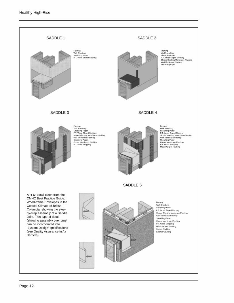
A ‘4-D’ detail taken from theCMHC Best Practice Guide:Wood-frame Envelopes in theCoastal Climate of BritishColumbia, showing the step-by-step assembly of a SaddleJoint. This type of detail(showing assembly over time)can be incorporated into‘System Design’ specifications(see Quality Assurance in AirBarriers).
SADDLE 1
SADDLE 3
SADDLE 2
SADDLE 4
SADDLE 5
FramingWall SheathingSheathing Paper P.T. Wood Sloped Blocking
FramingWall SheathingSheathing Paper P.T. Wood Sloped Blocking
FramingWall SheathingSheathing Paper P.T. Wood Sloped BlockingSloped Blocking Membrane FlashingWall Membrane FlashingSheathing Paper
FramingWall SheathingSheathing Paper P.T. Wood Sloped BlockingSloped Blocking Membrane FlashingWall Membrane FlashingSheathing PaperCorner Membrane FlashingP.T. Wood Strapping
FramingWall SheathingSheathing Paper P.T. Wood Sloped BlockingSloped Blocking Membrane FlashingWall Membrane FlashingSheathing PaperCorner Membrane FlashingP.T. Wood StrappingMetal Parapet Flashing
FramingWall SheathingSheathing Paper P.T. Wood Sloped BlockingSloped Blocking Membrane FlashingWall Membrane FlashingSheathing PaperCorner Membrane FlashingP.T. Wood StrappingMetal Parapet FlashingStucco CladdingExterior Caulking
Page 13
Enhancing Envelope Design
Test procedure ASTM E783 is used to performprogressive testing of individual assemblies andcomponents. In addition overall performance ofthe total air barrier system can be confirmedusing CAN/CGSB B2-149.15-M96.
4 Field Review / InspectionField reviews should verify that assemblies anddetails are constructed in conformance with thedesign documentation and that the specifiedmaterials are used. It is also necessary to confirmthat modifications or revisions arising fromconstruction and testing of mock-ups areincorporated. Field reviews are also required toaddress atypical details, or changes required as aresult of unforeseen circumstances arising duringconstruction. It is important that field reviewpersonnel be familiar with air barrier designconcepts as well as with the requirements in theproject brief.
5 DocumentationUpon completion of construction,a building operations manualshould be provided to the owner.The air barrier section of themanual should include:• the original project brief,• a description of building
operating conditions (RH levels,expected pressure differentials),
• design documents (including arecord of changes ormodifications made duringconstruction),
• a description of testing and testresults verifying compliancewith project brief requirements,
• monitoring and inspectionprocedures and maintenanceand repair requirements.
RETROFITOPPORTUNITIES
Retrofit of an effective air barriershould be considered in buildingenvelope renovation projects, or
where cladding is to be replaced. In most casesair barrier retrofit will be carried out in thecontext of a larger cladding or enveloperenovation project.
The effects of adding or changing materials on theoverall wall assembly need to be carefullyconsidered. Self-adhesive membranes, applied to theexterior of sheathing board, are often used in retrofitapplications to provide an air barrier. However theywill also act as a barrier to the diffusion of interiormoisture. If existing insulation on the interior side ofthe sheathing remains in place there is the potentialfor interstitial condensation. In this case an exteriorinsulation wall assembly should be considered. Itwill be necessary to remove sheathing to allowremoval of interior insulation and a polyethylenevapour barrier if provided. In many high-risebuilding envelope retrofit projects existing claddingwill be replaced with rainscreen cladding. The useof polyolefin house wrap type air barriers is notappropriate in this application.
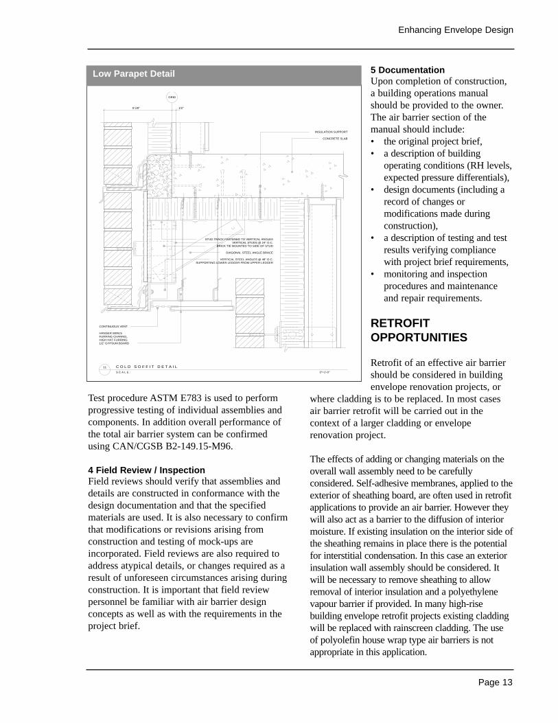
C O L D S O F F I T D E T A I L
GRID
DIAGONAL STEEL ANGLE BRACE
BRICK TIE MOUNTED TO SIDE OF STUD
INSULATION SUPPORT
CONTINUOUS VENT
FURRING CHANNELHANGER WIRES
HIGH HAT FURRING1/2" GYPSUM BOARD
VERTICAL STEEL ANGLES @ 48" O.C.SUPPORTING LOWER LEDGER FROM UPPER LEDGER
STUD TRACK FASTENED TO VERTICAL ANGLESVERTICAL STUDS @ 24" O.C.
CONCRETE SLAB
3"=1'-0"S C A L E :
11
8 5/8" 1/2"
Low Parapet Detail

Page 14
Healthy High-Rise
Sources of Information
• The Development of Test Procedures andMethods to Evaluate Air Barrier Membranesfor Masonry Walls, Ortech International forCMHC, 1990.
• National Building Code of Canada 1995,National Research Council Canada, 1995.
• An Air Barrier for the Building Envelope,Insitute for Research in Construction/NationalResearch Council Canada, 1986.
• Commissioning and Monitoring the BuildingEnvelope for Air Leakage, MorrisonHershfield for CMHC, 1994.
• Testing of Air Barrier Construction Details,CMHC, 1991 and 1993.
• EMPTIED Version 3, a computer program toaid in wall design by estimating potentialmonth-by-month moisture accumulationthrough air leakage and vapour diffusion,CMHC, 1998.
• ASTM E783 Standard Test Method for FieldMeasurement of Air Leakage throughInstalled Exterior Windows and Doors,American Society for Testing and Materials.
• Structural Requirements for Air Barriers,Morrison Hershfield for CMHC.
• Field Investigation Survey of Air Tightness,Air Movement and Indoor Air Quality inHigh-Rise Apartment Buildings, SummaryReport, Wardrop for CMHC.
• Air Permeance of Building Materials, Air Insfor CMHC.
• Airtightness Tests of Components Used toJoin Different or Similar Materials Materialsof the Building Envelope, CMHC.
• Commissioning and Monitoring the BuildingEnvelope for Air Leakage, MorrisonHershfield for CMHC.
• Testing of Air Barrier Systems for WoodframeWalls, Insitute for Research in Construction/National Research Council Canada, 1988.
• Air Barrier Update, S.Marshall, J.Rousseau,R.Quirouette, CMHC, 2000. Continuingeducation arcticle @ http://www.cmhc-schl.gc.ca/research/highrise/
• CMHC’s Best Practice Guides:@ http://www.cmhc-schl.gc.ca/rd-dr/en/hr-trs/e_guides.htm
Page 15
Enhancing Envelope Design
THE ISSUES
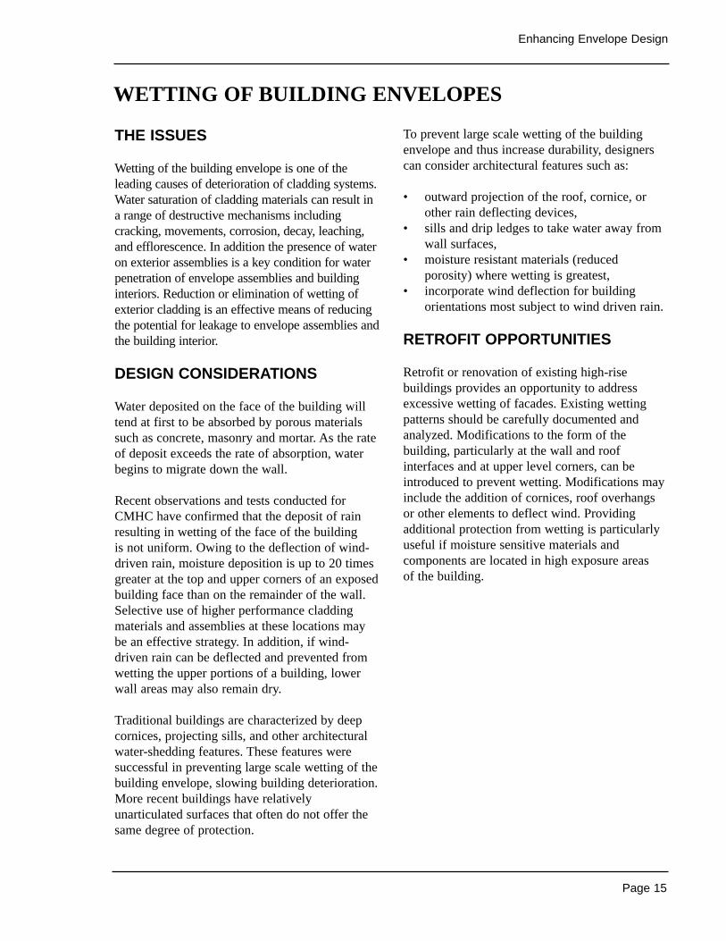
Wetting of the building envelope is one of theleading causes of deterioration of cladding systems.Water saturation of cladding materials can result ina range of destructive mechanisms includingcracking, movements, corrosion, decay, leaching,and efflorescence. In addition the presence of wateron exterior assemblies is a key condition for waterpenetration of envelope assemblies and buildinginteriors. Reduction or elimination of wetting ofexterior cladding is an effective means of reducingthe potential for leakage to envelope assemblies andthe building interior.
DESIGN CONSIDERATIONS
Water deposited on the face of the building willtend at first to be absorbed by porous materialssuch as concrete, masonry and mortar. As the rateof deposit exceeds the rate of absorption, waterbegins to migrate down the wall.
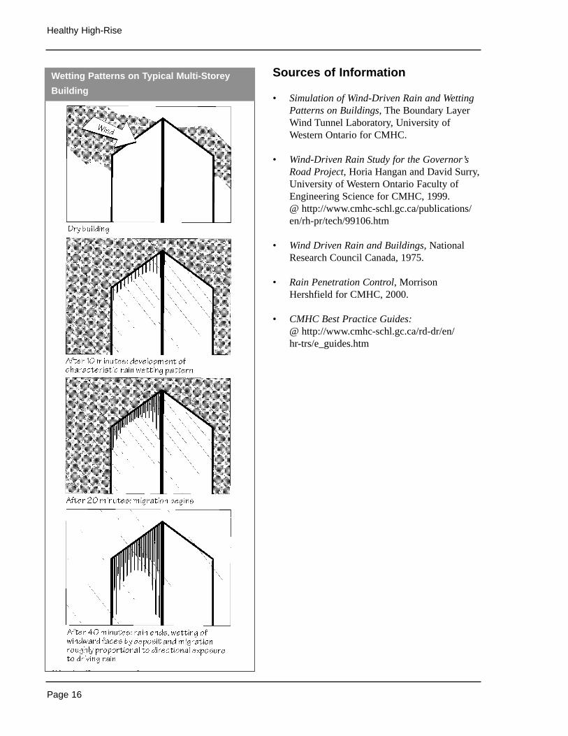
Recent observations and tests conducted forCMHC have confirmed that the deposit of rainresulting in wetting of the face of the building is not uniform. Owing to the deflection of wind-driven rain, moisture deposition is up to 20 timesgreater at the top and upper corners of an exposedbuilding face than on the remainder of the wall.Selective use of higher performance claddingmaterials and assemblies at these locations maybe an effective strategy. In addition, if wind-driven rain can be deflected and prevented fromwetting the upper portions of a building, lowerwall areas may also remain dry.
Traditional buildings are characterized by deepcornices, projecting sills, and other architecturalwater-shedding features. These features weresuccessful in preventing large scale wetting of thebuilding envelope, slowing building deterioration.More recent buildings have relativelyunarticulated surfaces that often do not offer thesame degree of protection.
To prevent large scale wetting of the buildingenvelope and thus increase durability, designerscan consider architectural features such as:
• outward projection of the roof, cornice, orother rain deflecting devices,
• sills and drip ledges to take water away fromwall surfaces,
• moisture resistant materials (reducedporosity) where wetting is greatest,
• incorporate wind deflection for buildingorientations most subject to wind driven rain.
RETROFIT OPPORTUNITIES
Retrofit or renovation of existing high-risebuildings provides an opportunity to addressexcessive wetting of facades. Existing wettingpatterns should be carefully documented andanalyzed. Modifications to the form of thebuilding, particularly at the wall and roofinterfaces and at upper level corners, can beintroduced to prevent wetting. Modifications mayinclude the addition of cornices, roof overhangsor other elements to deflect wind. Providingadditional protection from wetting is particularlyuseful if moisture sensitive materials andcomponents are located in high exposure areas of the building.
WETTING OF BUILDING ENVELOPES
Page 16
Healthy High-Rise
Sources of Information
• Simulation of Wind-Driven Rain and WettingPatterns on Buildings, The Boundary LayerWind Tunnel Laboratory, University ofWestern Ontario for CMHC.
• Wind-Driven Rain Study for the Governor’sRoad Project, Horia Hangan and David Surry,University of Western Ontario Faculty ofEngineering Science for CMHC, 1999.@ http://www.cmhc-schl.gc.ca/publications/en/rh-pr/tech/99106.htm
• Wind Driven Rain and Buildings, NationalResearch Council Canada, 1975.
• Rain Penetration Control, MorrisonHershfield for CMHC, 2000.
• CMHC Best Practice Guides:@ http://www.cmhc-schl.gc.ca/rd-dr/en/hr-trs/e_guides.htm
Wetting Patterns on Typical Multi-Storey
Building
Page 17
Enhancing Envelope Design
THE ISSUES
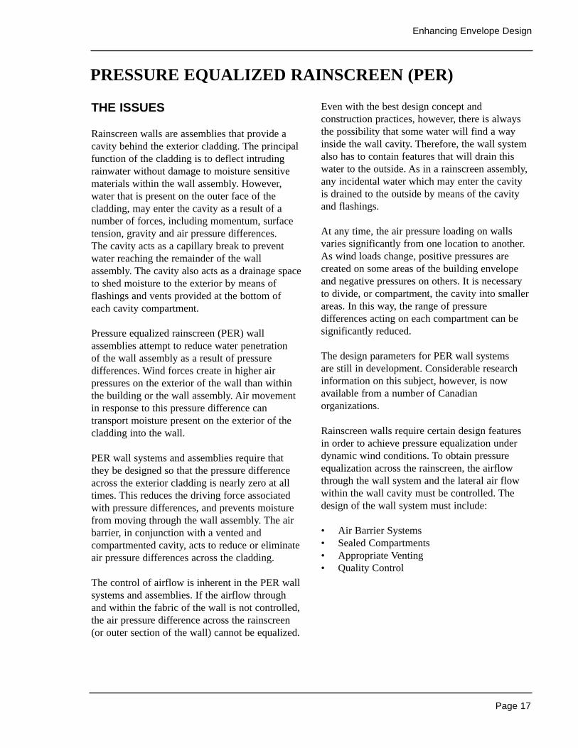
Rainscreen walls are assemblies that provide acavity behind the exterior cladding. The principalfunction of the cladding is to deflect intrudingrainwater without damage to moisture sensitivematerials within the wall assembly. However,water that is present on the outer face of thecladding, may enter the cavity as a result of anumber of forces, including momentum, surfacetension, gravity and air pressure differences. The cavity acts as a capillary break to preventwater reaching the remainder of the wallassembly. The cavity also acts as a drainage spaceto shed moisture to the exterior by means offlashings and vents provided at the bottom ofeach cavity compartment.
Pressure equalized rainscreen (PER) wallassemblies attempt to reduce water penetration of the wall assembly as a result of pressuredifferences. Wind forces create in higher airpressures on the exterior of the wall than withinthe building or the wall assembly. Air movementin response to this pressure difference cantransport moisture present on the exterior of thecladding into the wall.
PER wall systems and assemblies require thatthey be designed so that the pressure differenceacross the exterior cladding is nearly zero at alltimes. This reduces the driving force associatedwith pressure differences, and prevents moisturefrom moving through the wall assembly. The airbarrier, in conjunction with a vented andcompartmented cavity, acts to reduce or eliminateair pressure differences across the cladding.
The control of airflow is inherent in the PER wallsystems and assemblies. If the airflow throughand within the fabric of the wall is not controlled,the air pressure difference across the rainscreen(or outer section of the wall) cannot be equalized.
Even with the best design concept andconstruction practices, however, there is alwaysthe possibility that some water will find a wayinside the wall cavity. Therefore, the wall systemalso has to contain features that will drain thiswater to the outside. As in a rainscreen assembly,any incidental water which may enter the cavityis drained to the outside by means of the cavityand flashings.
At any time, the air pressure loading on wallsvaries significantly from one location to another.As wind loads change, positive pressures arecreated on some areas of the building envelopeand negative pressures on others. It is necessaryto divide, or compartment, the cavity into smallerareas. In this way, the range of pressuredifferences acting on each compartment can besignificantly reduced.
The design parameters for PER wall systems are still in development. Considerable researchinformation on this subject, however, is nowavailable from a number of Canadianorganizations.
Rainscreen walls require certain design featuresin order to achieve pressure equalization underdynamic wind conditions. To obtain pressureequalization across the rainscreen, the airflowthrough the wall system and the lateral air flowwithin the wall cavity must be controlled. Thedesign of the wall system must include:
• Air Barrier Systems • Sealed Compartments • Appropriate Venting• Quality Control
PRESSURE EQUALIZED RAINSCREEN (PER)
Page 18
Healthy High-Rise
DESIGN CONSIDERATIONS
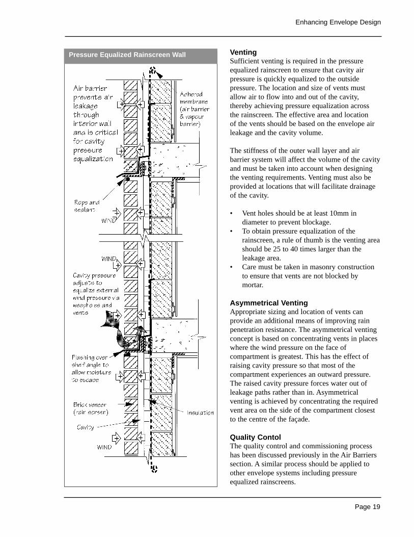
Air Barrier SystemsThe importance of the air barrier system toeffective building envelope performance has beendiscussed earlier in this section. Air barriers areparticularly important in pressure equalizedrainscreen wall assemblies.
The wall system must contain a continuous anddurable air barrier that controls airflow throughthe wall. The air barrier system must be made ofstructural elements, or be supported by structuralelements capable of resisting wind loads. The airbarrier system should be rigid to minimizematerial fatigue, especially at the points ofattachment to the structure.
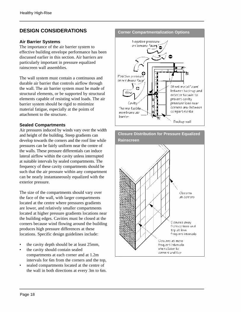
Sealed CompartmentsAir pressures induced by winds vary over the widthand height of the building. Steep gradients candevelop towards the corners and the roof line whilepressures can be fairly uniform near the centre ofthe walls. These pressure differentials can inducelateral airflow within the cavity unless interruptedat suitable intervals by sealed compartments. Thefrequency of these cavity compartments should besuch that the air pressure within any compartmentcan be nearly instantaneously equalized with theexterior pressure.
The size of the compartments should vary overthe face of the wall, with larger compartmentslocated at the centre where pressures gradients are lower, and relatively smaller compartmentslocated at higher pressure gradients locations nearthe building edges. Cavities must be closed at thecorners because wind flowing around the buildingproduces high pressure differences at theselocations. Specific design guidelines include:
• the cavity depth should be at least 25mm,• the cavity should contain sealed
compartments at each corner and at 1.2mintervals for 6m from the corners and the top,
• sealed compartments located at the centre ofthe wall in both directions at every 3m to 6m.
Corner Compartmentalization Options
Closure Distribution for Pressure Equalized
Rainscreen
Page 19
Enhancing Envelope Design
VentingSufficient venting is required in the pressureequalized rainscreen to ensure that cavity airpressure is quickly equalized to the outsidepressure. The location and size of vents mustallow air to flow into and out of the cavity,thereby achieving pressure equalization across the rainscreen. The effective area and location of the vents should be based on the envelope airleakage and the cavity volume.
The stiffness of the outer wall layer and airbarrier system will affect the volume of the cavityand must be taken into account when designingthe venting requirements. Venting must also beprovided at locations that will facilitate drainageof the cavity.
• Vent holes should be at least 10mm indiameter to prevent blockage.
• To obtain pressure equalization of therainscreen, a rule of thumb is the venting areashould be 25 to 40 times larger than theleakage area.
• Care must be taken in masonry constructionto ensure that vents are not blocked bymortar.
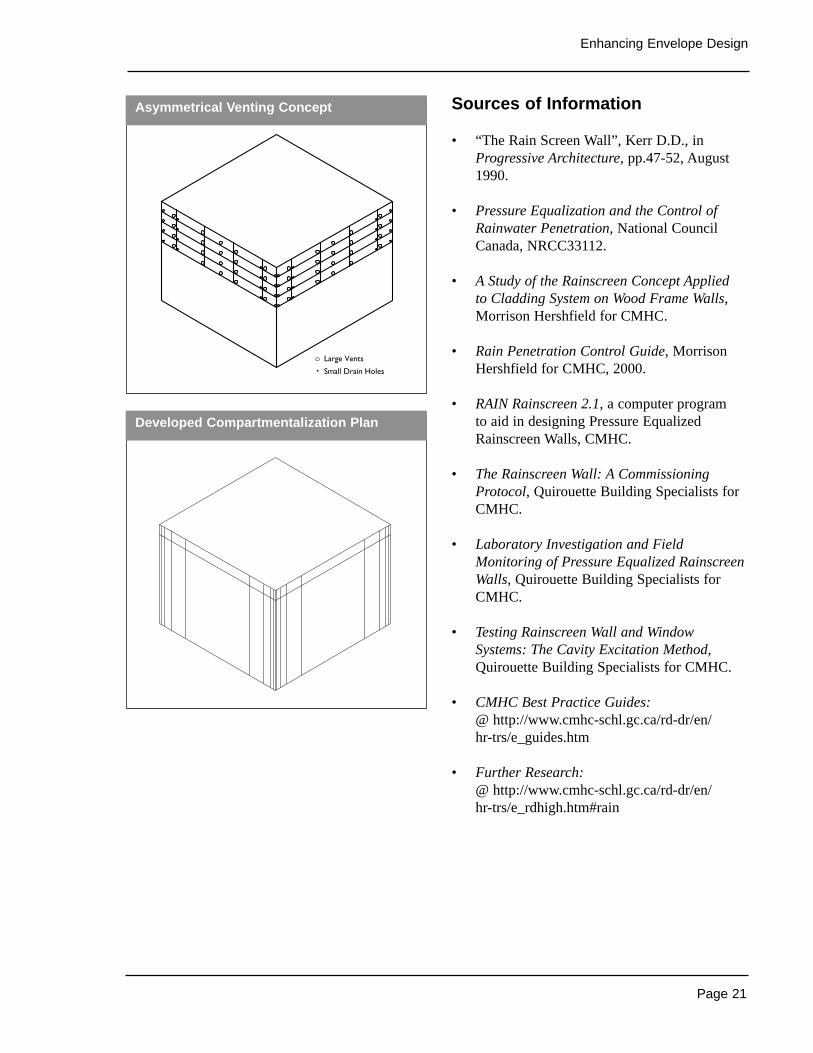
Asymmetrical VentingAppropriate sizing and location of vents canprovide an additional means of improving rainpenetration resistance. The asymmetrical ventingconcept is based on concentrating vents in placeswhere the wind pressure on the face ofcompartment is greatest. This has the effect ofraising cavity pressure so that most of thecompartment experiences an outward pressure.The raised cavity pressure forces water out ofleakage paths rather than in. Asymmetricalventing is achieved by concentrating the requiredvent area on the side of the compartment closestto the centre of the façade.
Quality Contol The quality control and commissioning processhas been discussed previously in the Air Barrierssection. A similar process should be applied toother envelope systems including pressureequalized rainscreens.
Pressure Equalized Rainscreen Wall
Page 20
Healthy High-Rise
The commissioning of a rainscreen wall willverify building performance objectives beforecompletion of construction. This is accomplishedthrough performance engineering and field orlaboratory testing. To assist with performanceengineering, CMHC has developed a computerprogram (RAIN) that simulates the pressureequalization (P.E.) performance of any design.
The quality control process for pressure equalizedrainscreen walls should include:
• determining that facade areas and windows tobe designed as pressure equalized rainscreens,
• locating vertical and horizontal compartmentsand determining the number of rainscreencavities,
• developing basic design of wall or windowsystem to include an air barrier system,compartment seals, and cladding system withvents/drains,
• determining physical attributes to eachrainscreen cavity i.e. volume, vent area,leakage area, and stiffness of cladding and air barrier systems,
• simulating the performance of eachrainscreen cavity using CMHC’s “RAIN”Rainscreen 2.1 and iterate the design untilperformance attributes are attained (90%pressure equalization),
• constructing a mock-up to test the P.E.performance of a design at pre-construction,
• assessing the complete design of envelopeand preparing construction documentation,
• preparing a tender package requiring on-sitemock-up test to verify field performance andworkmanship quality,
• complete testing of rainscreen wall andwindow system, correct problems as required,and report results,
• ensuring rainscreen P.E. performancecomplies with design objectives andcertifying that workmanship as complies withdrawing and specifications,
• providing design information necessary forproper maintenance of walls systems.
RETROFIT OPPORTUNITY
PERs should be used in all high-rise retrofit orrecladding projects. In addition to providing anappropriate level of water managementperformance, rainscreen assemblies also includean effective air barrier and offer an opportunity to add additional insulation to the exterior of thebuilding. Changing from face-sealed walls toraiscreen assemblies may result in additional wallthickness. Careful detailing will be required atinterfaces with components such as windows andother penetrations. In many older buildingsreplacing windows at the same time as recladdingwill allow for correct detailing of interfaces withwalls and will also improve overall envelopethermal performance. High-rise envelope retrofitprojects will often involve scaffolding of thebuilding exterior. The cost of providing access inthis manner is expensive; upgrading all envelopeassemblies and components at one time mayresult in lower life-cycle costs.
Page 21
Enhancing Envelope Design
Sources of Information
• “The Rain Screen Wall”, Kerr D.D., inProgressive Architecture, pp.47-52, August1990.
• Pressure Equalization and the Control ofRainwater Penetration, National CouncilCanada, NRCC33112.
• A Study of the Rainscreen Concept Applied to Cladding System on Wood Frame Walls,Morrison Hershfield for CMHC.
• Rain Penetration Control Guide, MorrisonHershfield for CMHC, 2000.
• RAIN Rainscreen 2.1, a computer program to aid in designing Pressure EqualizedRainscreen Walls, CMHC.
• The Rainscreen Wall: A CommissioningProtocol, Quirouette Building Specialists forCMHC.
• Laboratory Investigation and FieldMonitoring of Pressure Equalized RainscreenWalls, Quirouette Building Specialists forCMHC.
• Testing Rainscreen Wall and WindowSystems: The Cavity Excitation Method,Quirouette Building Specialists for CMHC.
• CMHC Best Practice Guides:@ http://www.cmhc-schl.gc.ca/rd-dr/en/hr-trs/e_guides.htm
• Further Research:@ http://www.cmhc-schl.gc.ca/rd-dr/en/hr-trs/e_rdhigh.htm#rain
Developed Compartmentalization Plan
Large Vents
Small Drain Holes
Asymmetrical Venting Concept
Page 22
Healthy High-Rise
Related Topics
Building EnvelopeSpace Heating and Air Conditioning
THE ISSUES
Exterior insulation and finish systems (EIFS) arelight weight exterior cladding systems consistingof insulation board mechanically and / oradhesively attached to a wind load-bearingsubstrate, and covered with an integrallyreinforced base coat and a protective surfacefinish. EIFS are based on the concept that optimalwall performance is achieved when all of thetemperature and moisture sensitive componentsare placed on the interior side of the insulation.To protect the insulation from the environmentwhile providing an architecturally pleasing finish,the insulation must be coated with a thin finishlayer. This layer needs to be reinforced to resistcracking from temperature, wind and structuralmovement.
The use of a source drained1 barrier approach tomoisture management is considered the minimumfor best practice for EIFS and is an essentialcomponent of any EIFS assembly. Moisture barrierprotection of the substrate, drainage and ventilationstrategies may also be required depending onparticular project and climatic conditions.
Advantages of EIFS include:
• location of the insulation protects the primarystructure from temperature extremes andmoisture-related damage,
• exterior insulation, particularly in steelframed buildings, can result in energysavings, and reduced cost of HVACequipment,
• complex surface features are possible in awide range of finish colours and textures,
• smaller dead loads and reduced structuralcosts,
• thinner walls will increase usable area andreduce building footprint,
• an EIFS can be pre-manufactured intranferrable panels.
Disadvantages include:
• sensitivity to deficiencies in workmanship,particularly at joints penetrations andsealants,
• susceptibility to mechanical damage.
Consideration should also be given to three keyelements of EIFS:
• Rain Penetration at Joints • Interstitial Condensation• Cracking of the Lamina
1 Drainage to the exterior of water in the assembly shouldoccur at the source of the water infiltration.
DESIGN CONSIDERATIONS
The most serious and widespread problemsassociated with EIFS relate to moisture damage,often to the substrate system or sheathing sinceEIFS themselves are made up of essentiallymoisture tolerant materials.
Rain Penetration at Joints
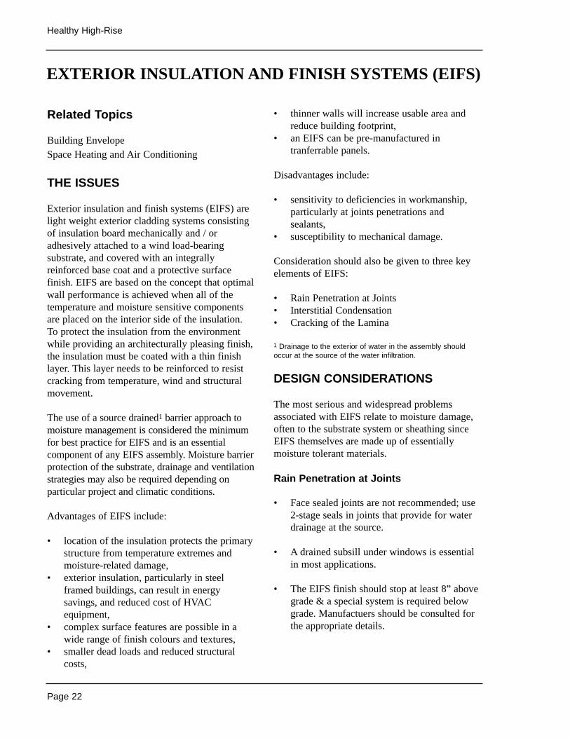
• Face sealed joints are not recommended; use2-stage seals in joints that provide for waterdrainage at the source.
• A drained subsill under windows is essentialin most applications.
• The EIFS finish should stop at least 8” abovegrade & a special system is required belowgrade. Manufactuers should be consulted forthe appropriate details.
EXTERIOR INSULATION AND FINISH SYSTEMS (EIFS)
Page 23
Enhancing Envelope Design
Interstitial Condensation
• Where possible, additional insulation shouldnot be placed in the stud space. This willmaintain the interior side surface temperatureof the substrate sheathing above the dewpoint of the interior air. If insulation isrequired in the stud space a dynamic analysisfor the prediction of condensation should becarried out prior to finalizing the design.
• A vapour barrier is required in EIFS cladwalls. A membrane or trowel applied vapourbarrier can be used between the insulationboard and the sheathing. Alternatively, aseparate vapour barrier on the inside of thewall can be provided.
Cracking of the Lamina
• Cracking caused by excessive stresses canoccur as a result of inappropriate location of joints between insulation boards, orinsufficient or inappropriate control andmovement joint spacing and location.
• EIFS with thin glass-mesh reinforced high-polymer content laminas may experiencedurability and performance problems if themesh is not properly embedded in a base coat of the proper thickness. The base coatprovides the primary water penetrationresistance, and when reinforced, the majorityof the structural properties of the lamina.
Sources of Information
• Exterior Insulated Finish System LabroratoryEvaluation of Joints and Materials Subjectedto Artificial Conditioning, Lawrence Gibsonfor CMHC,1995. @ http://www.cmhc-schl.gc.ca/publications/en/rh-pr/tech/96230.htm
• Exterior Insulated Finish System FieldPerformance Evaluation, James Posey & John A. Vlooswyk for CMHC, 1993.@ http://www.cmhc-schl.gc.ca/publications/en/rh-pr/tech/98118.htm
• Exterior Insulated Finish System, Problems,Causes and Solutions, CMHC,1991.
• EASE computer program to analysecondensation potential of wall systems,CMHC.
Drain/Vent
Caulking
Backer Rod
Rainscreen Joint Between Face-Sealed
Elements
Page 24
Healthy High-Rise
Related Topics
Source Reduction
THE ISSUES
Parking structures are subjected to demandingservice conditions. These include live load effectssuch as vehicular impact and abrasion as well asenvironmental effects such as high humidity andmoisture levels, thermal variations, and attackfrom de-icing salts. Together, these factors canlead to premature deterioration of parkingstructures.
The primary cause of parking structure failure isattributed to corrosion of the reinforcing steel dueto chlorine ions from road salts. The overall costof repairs to parking structures in Canada isestimated at 1.5 to 3 billion dollars. Studies showthat the repair costs for individual structures canexceed the original construction costs.
DESIGN CONSIDERATIONS
The 1995 NBC requires parking structures to bedesigned in conformance with CAN/CSAS-413-94, which requires measures to protect parkingstructures from the ingress of moisture and salts,the primary contributors to deterioration.Specifications are provided for protectivemembranes, and epoxy coatings of reinforcingbars are required for the various structuralelements.
Designers and contractors should further mitigatepotential problems by:
• ensuring positive drainage,• by minimizing cracks in concrete,• through careful placement of expansion and
construction joints,• through improved quality control during the
application of surface protection systems.
Positive DrainageParking slabs must have adequate slope andproperly positioned drains to ensure rapid run-off ofwater. A minimum slope of 2% is recommended.
Reduced CrackingConcrete mix and placement procedures must becontrolled to minimize shrinkage cracks.Shrinkage cracks must be treated prior toinstallation of surface protection systems.
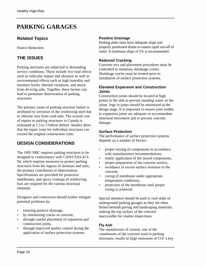
Elevated Expansion and ConstructionJointsConstruction joints should be located at highpoints in the slab to prevent standing water on thejoints. Jogs in joints should be minimized at thedesign stage. It is important to ensure joint widthsin expansion joints are adequate to accommodatestructural movement and to prevent concretedamage.
Surface ProtectionThe performance of surface protection systemsdepends on a number of factors:
• proper mixing of components in accordancewith manufacturers recommendations,
• timely application of the mixed components,• proper preparation of the concrete surface,• avoidance of excess surface moisture in the
concrete,• curing of membrane under appropriate
temperature conditions,• protection of the membrane until proper
curing is achieved.
Special attention should be paid to roof slabs ofunderground parking garages as they are oftenburied beneath paving and landscaping materials,making the top surface of the concreteinaccessible for routine inspections.
Fly AshThe manufacture of cement, one of theconstituents of the concrete used in parkingstructures, results in large emissions of CO2 a key
PARKING GARAGES
Page 25
Enhancing Envelope Design
greenhouse gas. Emissions of CO2 result bothfrom the use of fossil fuels during the cementmanufacturing process, and from the processitself. Production of one tonne of cement releases1.25 tonnes of CO2, approximately 0.75 tonnesfrom energy use, and 0.5 tonnes from thecalcinating of limestone during manufacture.
Replacing a portion of the cement with fly ash, aby-product of coal burning power plants canreduce the environmental impacts of concrete use.Fly ash has traditionally been added to concretemixes in quantities up to 15%. However it ispossible to use larger volumes, up to 70% forsome applications, in place of cement. Theaddition of fly ash enhances many of the qualitiesof the finished concrete, making it stronger, lesspermeable to water, and more durable. Whileworkability and pumpability are also improved,concrete containing high volumes of fly ash doestake longer to set and gain initial strength. Forthis reason it is not suitable for applicationswhere rapid removal of forms is required.
Fly ash is less expensive than concrete and its usecan result cost savings, although mixes using flyash may require additional admixtures reducingpotential savings.
RETROFIT OPPORTUNITY
Renovation of parking garages typically involveslocalized repair of deteriorated concrete andreplacement of corroded steel reinforcing.
Sources of Information
• CAN/CSA Standard S-413-94 “ParkingStructures”.
• Summary of Concrete Findings, CMHC,1994.
• Effective Installation of Membranes onParking Garage Decks, ConstructionTechnology Update No. 29, MailvaganamN.P. and P.G. Collins, NRC 1999.
Expansion Joint at Parking Level

Page 26
Healthy High-Rise
Related Topics
Landscape Practices
THE ISSUES
Sloped roofs have typically not been used on high rise buildings. They may, however, provideimproved performance when compared to flatroofs, and their use should be considered. Flatroofs, or more properly low-sloped membraneroofs, are the most common roofing assembly usedon high rise buildings. When properly designed andconstructed, low slope membrane roof systemsshould be capable of lasting in excess of 20 years.
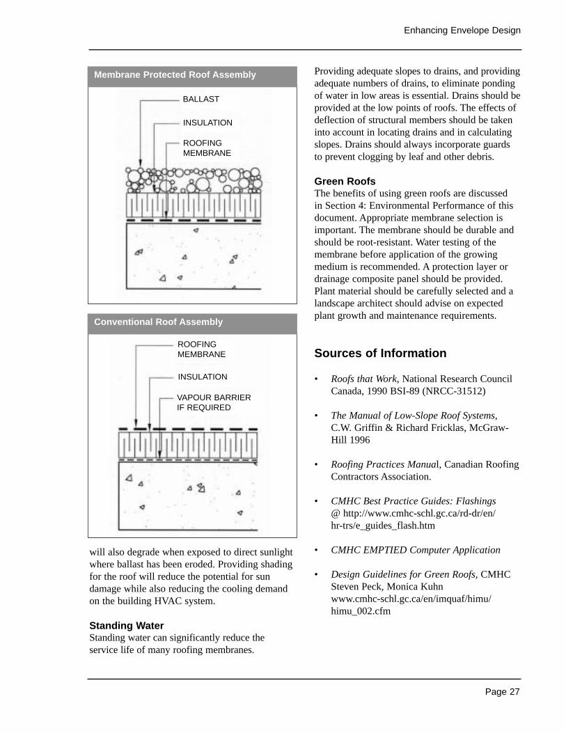
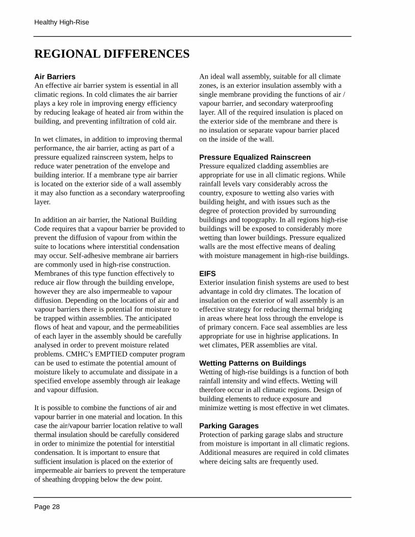
There are two basic low-slope roofing assemblies,both of which have 3 basic components: a membrane,insulation, and a structural substrate (a vapourretarder is also sometimes required, particularly inhigh humidity buildings in cold climates). Theassemblies differ primarily in the location of themembrane relative to the insulation layer. In aconventional assembly, the membrane is locatedabove the insulation layer and is exposed to allenvironmental loads. In a protected membraneassembly, the membrane is located below, and isprotected by the insulation layer. An additional ballastlayer is required to hold the insulation in place.
Various membranes may be used on low-sloperoofs. The principal types are:
• Asphalt based membranes• 1 Built up roof (BUR)• 2 Modified bitumen (SBS)• Polymer based membranes• 1 Thermosetting - EPDM• 2 Thermoplastic - PVC
Failure mechanisms vary depending on the type of membrane. Blistering and ridging are problemswith BUR and SBS roofs, lap defects can affectSBS and EPDM membranes, while embrittlementand shrinkage can cause failures in PVC.
Water leakage is the most obvious indicator offailing roof systems. Thermography may beuseful in identifying areas of wet insulation inmost conventional roof assemblies, although theapplications of this process are somewhat limited.
Improved practice would include running the roofmembrane to extend over the parapet. Metalcounter flashing can then ensure that leakage into or around the parapet is restricted. Carefuldetailing and installation of all penetrationsthrough the membrane (plumbing stacks, fireplaceflues, exhaust fans, etc.) is required to preventleakage. Other important considerations include:
• Seams• Membrane Moisture• Ballast• Standing Water
DESIGN CONSIDERATIONS
SeamsDetailing and construction of seams in sheetmaterials can also result in leakage. Most of theseproblems occur as a result of deviations frommanufacturers’ recommended installationprocedures.
Membrane MoistureMoisture accumulating underneath the membranecan also result in delamination of the membranefrom the roof deck and eventual leakage. Thismoisture can be the result of air leakage andmoisture migration from within the building,especially around plumbing stacks, and throughpenetrations provided for mechanical equipment.Continuity of the air barrier must includeappropriate detailing of roof assemblies.
Inadequate BallastInadequate ballast can result in floating andseparation of insulation materials. Ballast settlingbetween insulation (sheets as they float willdisrupt continuity of the insulation and potentiallydamage the membrane). Many insulation products
LOW SLOPE ROOFING SYSTEMS
Page 27
Enhancing Envelope Design
will also degrade when exposed to direct sunlightwhere ballast has been eroded. Providing shadingfor the roof will reduce the potential for sundamage while also reducing the cooling demandon the building HVAC system.
Standing WaterStanding water can significantly reduce theservice life of many roofing membranes.
Providing adequate slopes to drains, and providingadequate numbers of drains, to eliminate pondingof water in low areas is essential. Drains should beprovided at the low points of roofs. The effects ofdeflection of structural members should be takeninto account in locating drains and in calculatingslopes. Drains should always incorporate guards to prevent clogging by leaf and other debris.
Green RoofsThe benefits of using green roofs are discussed in Section 4: Environmental Performance of thisdocument. Appropriate membrane selection isimportant. The membrane should be durable andshould be root-resistant. Water testing of themembrane before application of the growingmedium is recommended. A protection layer ordrainage composite panel should be provided.Plant material should be carefully selected and alandscape architect should advise on expectedplant growth and maintenance requirements.
Sources of Information
• Roofs that Work, National Research CouncilCanada, 1990 BSI-89 (NRCC-31512)
• The Manual of Low-Slope Roof Systems,C.W. Griffin & Richard Fricklas, McGraw-Hill 1996
• Roofing Practices Manual, Canadian RoofingContractors Association.
• CMHC Best Practice Guides: Flashings @ http://www.cmhc-schl.gc.ca/rd-dr/en/hr-trs/e_guides_flash.htm
• CMHC EMPTIED Computer Application
• Design Guidelines for Green Roofs, CMHCSteven Peck, Monica Kuhn www.cmhc-schl.gc.ca/en/imquaf/himu/himu_002.cfm
Membrane Protected Roof Assembly
Conventional Roof Assembly
BALLAST
INSULATION
ROOFINGMEMBRANE
VAPOUR BARRIERIF REQUIRED
INSULATION
ROOFINGMEMBRANE
Page 28
Healthy High-Rise
Air BarriersAn effective air barrier system is essential in allclimatic regions. In cold climates the air barrierplays a key role in improving energy efficiencyby reducing leakage of heated air from within thebuilding, and preventing infiltration of cold air.
In wet climates, in addition to improving thermalperformance, the air barrier, acting as part of apressure equalized rainscreen system, helps toreduce water penetration of the envelope andbuilding interior. If a membrane type air barrier is located on the exterior side of a wall assemblyit may also function as a secondary waterproofinglayer.
In addition an air barrier, the National BuildingCode requires that a vapour barrier be provided toprevent the diffusion of vapour from within thesuite to locations where interstitial condensationmay occur. Self-adhesive membrane air barriersare commonly used in high-rise construction.Membranes of this type function effectively toreduce air flow through the building envelope,however they are also impermeable to vapourdiffusion. Depending on the locations of air andvapour barriers there is potential for moisture tobe trapped within assemblies. The anticipatedflows of heat and vapour, and the permeabilitiesof each layer in the assembly should be carefullyanalysed in order to prevent moisture relatedproblems. CMHC’s EMPTIED computer programcan be used to estimate the potential amount ofmoisture likely to accumulate and dissipate in aspecified envelope assembly through air leakageand vapour diffusion.
It is possible to combine the functions of air andvapour barrier in one material and location. In thiscase the air/vapour barrier location relative to wallthermal insulation should be carefully consideredin order to minimize the potential for interstitialcondensation. It is important to ensure thatsufficient insulation is placed on the exterior ofimpermeable air barriers to prevent the temperatureof sheathing dropping below the dew point.
An ideal wall assembly, suitable for all climatezones, is an exterior insulation assembly with asingle membrane providing the functions of air /vapour barrier, and secondary waterproofinglayer. All of the required insulation is placed onthe exterior side of the membrane and there is no insulation or separate vapour barrier placed on the inside of the wall.
Pressure Equalized RainscreenPressure equalized cladding assemblies areappropriate for use in all climatic regions. Whilerainfall levels vary considerably across thecountry, exposure to wetting also varies withbuilding height, and with issues such as thedegree of protection provided by surroundingbuildings and topography. In all regions high-risebuildings will be exposed to considerably morewetting than lower buildings. Pressure equalizedwalls are the most effective means of dealingwith moisture management in high-rise buildings.
EIFSExterior insulation finish systems are used to bestadvantage in cold dry climates. The location ofinsulation on the exterior of wall assembly is aneffective strategy for reducing thermal bridging in areas where heat loss through the envelope isof primary concern. Face seal assemblies are lessappropriate for use in highrise applications. Inwet climates, PER assemblies are vital.
Wetting Patterns on BuildingsWetting of high-rise buildings is a function of bothrainfall intensity and wind effects. Wetting willtherefore occur in all climatic regions. Design ofbuilding elements to reduce exposure andminimize wetting is most effective in wet climates.
Parking GaragesProtection of parking garage slabs and structurefrom moisture is important in all climatic regions.Additional measures are required in cold climateswhere deicing salts are frequently used.
REGIONAL DIFFERENCES
Page 29
In This Section
Building Envelope• windows & solar control• air leakage• insulation systems• thermal bridging
Space Heating & Air Conditioning• integrated design process• electric heating systems• natural gas heating• HVAC distribution systems
Other Systems• control systems• individual suite metering• motors• auxiliary electric motors• domestic hot water
Lighting & Appliances• lighting• appliances
Alternative Energy Supply Systems• co-generation• ground source heat pumps• fuel cells• solar energy• daylighting• passive cooling• wind turbines
Case Studies
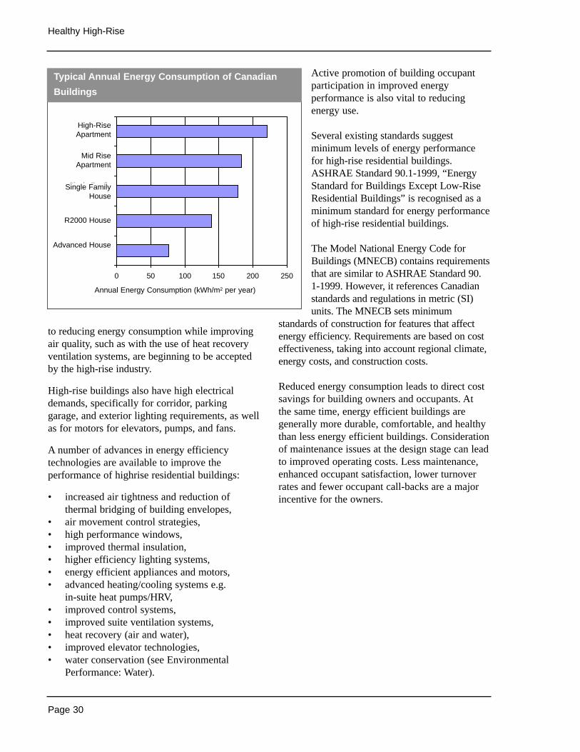
Highrise residential buildings represent 10% ofall dwelling units in Canada and are majorconsumers of energy. On a floor area basis, theyconsume more energy than single familydwellings - even though the highrise unit hasmuch less exposed exterior surface. And whencompared to the leading edge Advanced Housestandards for energy consumption, multi-unitresidential buildings consume three times theamount of energy per unit of floor area.
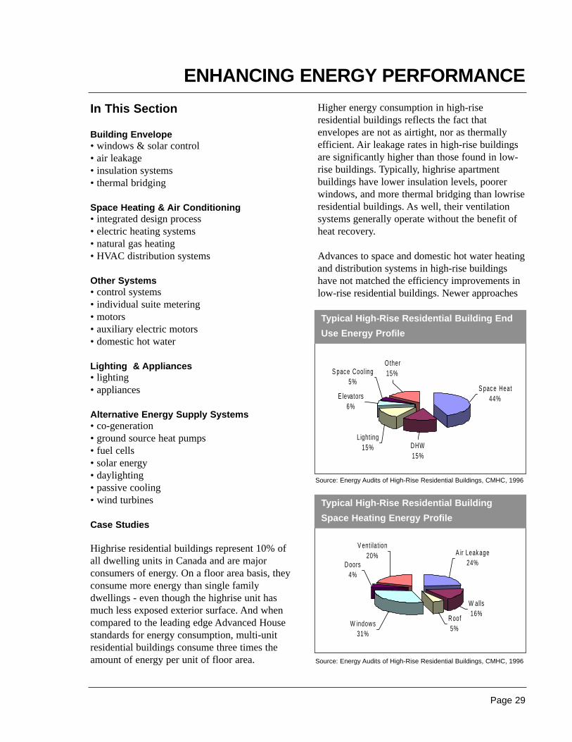
Higher energy consumption in high-riseresidential buildings reflects the fact thatenvelopes are not as airtight, nor as thermallyefficient. Air leakage rates in high-rise buildingsare significantly higher than those found in low-rise buildings. Typically, highrise apartmentbuildings have lower insulation levels, poorerwindows, and more thermal bridging than lowriseresidential buildings. As well, their ventilationsystems generally operate without the benefit ofheat recovery.
Advances to space and domestic hot water heatingand distribution systems in high-rise buildingshave not matched the efficiency improvements inlow-rise residential buildings. Newer approaches
ENHANCING ENERGY PERFORMANCE
gy
S pac e Heat44%
DHW15%
Light ing15%
O ther 15%S pac e Cooling
5%
E levators6%
Typical High-Rise Residential Building End
Use Energy Profile
W indows31%
Doors4%
V ent ilat ion20%
Roof5%
W alls16%
A ir Leak age24%
Typical High-Rise Residential Building
Space Heating Energy Profile
Source: Energy Audits of High-Rise Residential Buildings, CMHC, 1996
Source: Energy Audits of High-Rise Residential Buildings, CMHC, 1996
Page 30
Healthy High-Rise
to reducing energy consumption while improvingair quality, such as with the use of heat recoveryventilation systems, are beginning to be acceptedby the high-rise industry.
High-rise buildings also have high electricaldemands, specifically for corridor, parkinggarage, and exterior lighting requirements, as wellas for motors for elevators, pumps, and fans.
A number of advances in energy efficiencytechnologies are available to improve theperformance of highrise residential buildings:
• increased air tightness and reduction ofthermal bridging of building envelopes,
• air movement control strategies,• high performance windows,• improved thermal insulation,• higher efficiency lighting systems,• energy efficient appliances and motors,• advanced heating/cooling systems e.g.
in-suite heat pumps/HRV,• improved control systems,• improved suite ventilation systems,• heat recovery (air and water),• improved elevator technologies,• water conservation (see Environmental
Performance: Water).
Active promotion of building occupantparticipation in improved energyperformance is also vital to reducingenergy use.
Several existing standards suggestminimum levels of energy performancefor high-rise residential buildings.ASHRAE Standard 90.1-1999, “EnergyStandard for Buildings Except Low-RiseResidential Buildings” is recognised as aminimum standard for energy performanceof high-rise residential buildings.
The Model National Energy Code forBuildings (MNECB) contains requirementsthat are similar to ASHRAE Standard 90.1-1999. However, it references Canadianstandards and regulations in metric (SI)units. The MNECB sets minimum
standards of construction for features that affectenergy efficiency. Requirements are based on costeffectiveness, taking into account regional climate,energy costs, and construction costs.
Reduced energy consumption leads to direct costsavings for building owners and occupants. At the same time, energy efficient buildings aregenerally more durable, comfortable, and healthythan less energy efficient buildings. Considerationof maintenance issues at the design stage can leadto improved operating costs. Less maintenance,enhanced occupant satisfaction, lower turnoverrates and fewer occupant call-backs are a majorincentive for the owners.
0 50 100 150 200 250
Advanced House
R2000 House
Single FamilyHouse
Mid RiseApartment
High-RiseAparment
Annual Energy Consumption (kWh/m2 per year)
Typical Annual Energy Consumption of Canadian
Buildings
High-RiseApartment
Mid RiseApartment
Single FamilyHouse
R2000 House
Advanced House
Annual Energy Consumption (kWh/m2 per year)
Page 31
Enhancing Energy Performance
Related Topics
Air BarriersExterior Insulation and Finish System (EIFS)Space Heating and Air ConditioningAlternative Energy Supply SystemsMechanical VentilationSite PlanningLandscape PracticesOccupant Comfort - Noise
THE ISSUES
The building envelope plays a critical role in the energy performance of high-rise residentialbuildings. Designers can reduce buildingenvelope related energy losses by reducing airleakage through the envelope, using highperformance windows, increasing insulationlevels, and minimising thermal bridging.
Poorly performing thermal envelopes can result in:
• high utility costs to the building occupants orowner (depending on the metering strategy),
• occupant discomfort due to cold surfaces,drafts, radiant heat losses, overheating andmovement of odours,
• deterioration of interior finishes and exteriormaterials from condensation,
• poor indoor air quality from condensationrelated mold growth.
Poor performance is commonly a function of:
• a lack of continuity of the air barrier system,• inadequate thermal resistance of envelope
components,• thermal bridging to the outside (eg. via floor
slabs, shear walls, steel studs),• selection of materials and components (shelf
angles, balconies and foundations) onlyconsidering the lowest cost,
• poor installation practices and lack of qualitycontrol (including commissioning).
Good thermal envelope design practice shouldprovide:
• low air leakage,• higher thermal resistance of exterior envelope
components,• high performance glazing systems,• elimination of thermal bridging,• reduced summertime solar heat gains and
winter heat loss.
Achieving good design is possible by consideringthe importance of the following key elements:
• Windows & Solar Control• Air Leakage• Insulation Systems• Thermal Bridging
DESIGN CONSIDERATIONS
Windows and Solar ControlHeat loss through windows is one of the mostsignificant components of space heating load inhigh rise residential buildings. The typical Rvalue of a window is less than one tenth that ofinsulated walls. Yet in many cases, windowsrepresent the largest component of the wall area.
New energy efficient windows save heating andcooling energy costs, reduce windowcondensation and improve occupant comfort aswell. Suites will be much more comfortable year-round due to reduced discomfort from radiantheat loss to cold window surfaces, and areduction in cold drafts.
Better insulated windows reduce or eliminatecondensation which can obscure views, causedamage to sills, finishes and walls, reduce the lifeof glazing seals, and cause mold related healthproblems. Good window design can also reduceoverheating in the summer, leading to reducedenergy consumption for cooling and heating andimproved occupant comfort.
BUILDING ENVELOPE

Page 32
Healthy High-Rise
In addition to satisfying the requirement ofcontrolling conductive heat loss, windows mustalso control moisture flows, infiltration air flow,solar heat gains, and natural ventilation airflow.Improved window performance also requiresproper installation to ensure that the window-wallinterface keeps out water and maintains theintegrity of the walls air barrier system. Poorinstallation will undermine the energy andcomfort performance improvements of even thebest windows.
High thermal performancewindows have:
• low-emissivity glazing,• inert gas fills between window
panes,• advanced framing materials
and designs and• insulating spacers.
Window size and solar and thermalcharacteristics should be specifiedby wall orientation to achieve theoptimum energy efficiency balancebetween maximised winter solargains, minimised winter heat loss,and minimised summer solar gains.For residential buildings in Canadathis usually means maximising theinsulation value of windows in allorientations. To reduce summerheat gains, south and particularlywest facing windows can bereduced in size. Coloured glazingcan be used and external shadingdevices can also be employed.
When high performance windowsare analysed on a life cycle basis,the incremental cost of addinglow-e coatings and argon fill todouble pane windows is easilyoffset by energy savings in mostregions. Low-e coatings, argon filland casement style windows
(instead of sliding because of lower air leakage)are generally found to be the features with thegreatest energy efficiency benefit for cost. Thetrue value of high performance windows shouldalso consider the reduced maintenance costs,reduced mechanical equipment sizes, and thevalue of improved occupant comfort, ease of use,security, and health implications.
Several other window design and installationissues affect building energy efficiency. Airleakage resistance should be appropriatelyspecified according to the CAN/CSA-A440Standard. The location of the window in terms of
Window Head
Page 33
Enhancing Energy Performance
height and wind speed exposure, and reduceenergy losses due to air leakage must beconsidered. The window must also be properlysealed into the window opening to maintain the airleakage resistance of the window to wall interface.
Air conditioning requirements can be reduced bymaximising natural ventilation airflow through thedesign and placement of windows. To maximisesingle sided natural ventilation in apartments, theopenable area of windows should be as large aspossible. Window opening areas should be separatedby as much height as possible to take advantage ofroom stack effect (ie. tall windows with openings atthe top and bottom). Windows should also belocated to take maximum advantage of any crossventilation possibilities. Solar protective glazing andexternal solar shading devices will also reduce solargains and resulting cooling requirements.
Air Leakage Next to heat losses through windows, the greatestcontributor to space heating energy use in mosthigh rise residential buildings is the energyrequired to heat unintentional air leakage into thebuilding. Stack, wind, and the ventilation systeminduce pressure differences between the inside andoutside of the building. These pressure differencescause outside air leakage into the building. Energyis then required to heat or cool incoming air.
Air leakage also causes:
• occupant discomfort associated with colddrafts and heat stratification (ie. hot air risingto upper floors and cold air at lower floorscauses upper floor occupants to compensateby opening their windows and lower flooroccupants to turn up their heat),
• movement of odours from suite to suite,• moisture-related building envelope
deterioration and health related concerns,• poor indoor air quality,• difficulty designing effective smoke control
systems.
Air leakage can reverse the intended flow ofventilation air resulting in under-ventilation ofsome suites in a building and over-ventilation of
others. To avoid these problems, a well designedbuilding should be as airtight as possible, withmechanical ventilation systems supplyingventilation air independently of air leakage (buildtight, ventilate right).
Methods for improving the air tightness of wallsand windows of the building are found in theEnhancing Envelope Design section of thisdocument. Particular attention should also bemade to sealing intentional or unintentionalvertical shafts within the building. Air leakagecontributions to stack induced air movementthrough elevator and stairway shafts, mechanical,plumbing and electrical shafts, garbage chutes,and vertical ventilation and exhaust ductwork.
All vertical shafts should be designed to minimisepotential airflow with the rest of the building ateach floor level, with particular attention paid tolocations near the top and bottom of each shaft.Maximum allowable airflow leakage rates shouldbe specified for all doors, windows, and dampersconnected to vertical shafts.
Elevator doors should be tight fitting, withpotential airflow openings minimised at the top of elevator shafts. Doors, windows and walls inelevator penthouses should be well sealed.Alternative elevator systems are available for lowrise buildings (up to 7 stories) that eliminate theneed for elevator machine rooms. This canremove a major air leakage source at the roof.Automatic dampers are needed to shut off airflowthough corridor supply ducts and vertical exhaustsystems when fans are off. Smoke vents invertical shafts should be provided with automaticdampers with smoke sensors. Plumbing,electrical, and ductwork penetrations throughfloors should be inspected to ensure that they arewell sealed. Garbage chute doors and doors tochute rooms should also be gasketed.
Understanding of air leakage patterns in high riseapartment buildings has progressed to the pointwhere air tightness specialists can be retained to develop air leakage specifications, traincontractors, inspect and test construction, andcertify compliance.
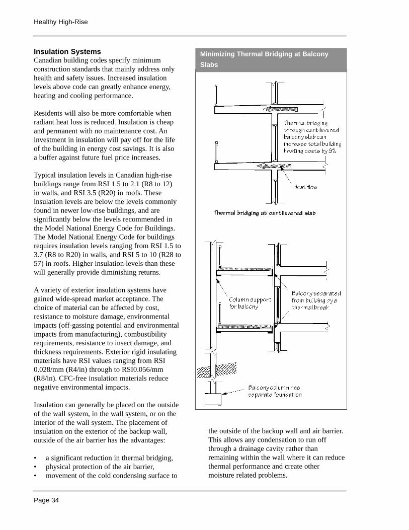
Page 34
Healthy High-Rise
Insulation SystemsCanadian building codes specify minimumconstruction standards that mainly address onlyhealth and safety issues. Increased insulationlevels above code can greatly enhance energy,heating and cooling performance.
Residents will also be more comfortable whenradiant heat loss is reduced. Insulation is cheapand permanent with no maintenance cost. Aninvestment in insulation will pay off for the lifeof the building in energy cost savings. It is also a buffer against future fuel price increases.
Typical insulation levels in Canadian high-risebuildings range from RSI 1.5 to 2.1 (R8 to 12) in walls, and RSI 3.5 (R20) in roofs. Theseinsulation levels are below the levels commonlyfound in newer low-rise buildings, and aresignificantly below the levels recommended inthe Model National Energy Code for Buildings.The Model National Energy Code for buildingsrequires insulation levels ranging from RSI 1.5 to3.7 (R8 to R20) in walls, and RSI 5 to 10 (R28 to57) in roofs. Higher insulation levels than thesewill generally provide diminishing returns.
A variety of exterior insulation systems havegained wide-spread market acceptance. Thechoice of material can be affected by cost,resistance to moisture damage, environmentalimpacts (off-gassing potential and environmentalimpacts from manufacturing), combustibilityrequirements, resistance to insect damage, andthickness requirements. Exterior rigid insulatingmaterials have RSI values ranging from RSI0.028/mm (R4/in) through to RSI0.056/mm(R8/in). CFC-free insulation materials reducenegative environmental impacts.
Insulation can generally be placed on the outsideof the wall system, in the wall system, or on theinterior of the wall system. The placement ofinsulation on the exterior of the backup wall,outside of the air barrier has the advantages:
• a significant reduction in thermal bridging,• physical protection of the air barrier,• movement of the cold condensing surface to
the outside of the backup wall and air barrier.This allows any condensation to run offthrough a drainage cavity rather thanremaining within the wall where it can reducethermal performance and create othermoisture related problems.
Minimizing Thermal Bridging at Balcony
Slabs
Page 35
Enhancing Energy Performance
A drawback of this approach is the reduction inbuildable floor area allowed by jurisdictions thatuse outside building dimensions to calculatemaximum allowable floor space ratios.
Regardless of location, the insulation should beinstalled in a manner which avoids excessivecompression and reduces thermal bridging, andgaps and air spaces. Mechanical fastening of rigidinsulation products should be designed to preventexcessive compression that reduces thermalperformance, minimise the effects of thermalbridging, and allow for thermal movement.Installation of insulation should ensureminimisation of gaps and spaces that can allowconvective loops and reduce thermal performance.To prevent air circulation, rigid insulation shouldbe fastened in continuous contact with the airtightplane, preventing air circulation around theinsulation. Where gaps are required betweensheets of rigid insulation to allow for thermalexpansion or structural movement, the gaps shouldbe filled with bat insulation.
Designers must also consider exposure to moistureand high temperatures when specifying roofinsulation products. To reduce thermal bridging inrigid insulation roofing systems, insulation boardsmust be tightly installed to prevent roof ballastfrom working its way between sheets. Shiplapjoints represent a means of better ensuringcontinuity of the insulation coverage.
Thermal BridgingAttention is too often focused on the maininsulating components of exterior walls withoutconsidering that localised thermal bridging cansignificantly increase the heat loss. Thermalbridges are locations of minimal thermal resistancethat allow heat to flow directly to the exterior.Thermal bridges can also act as radiant fins such as with non thermally broken balcony slabs. In allcases they have a significant effect on buildingheat loss. Balcony slabs, shear walls, spandrelbeams, window frames, shelf angles, and parapetwalls all represent areas which provide minimalresistance to heat flow between the interior of thebuilding and the exterior. Thermal bridging at theselocations can cause frosting and condensation on
interior finishes, and discomfort from cold wallsand cold floors adjacent to balconies.
Higher performance building envelopes eliminatepotential thermal bridging problems. Exteriorapplied insulation can significantly reduce manythermal bridging problems found in exterior wallssince it can cover locations such as floor slabs thatcannot be insulated from inside the wall or building.
Balcony slabs represent a particularly weak pointin the thermal envelope, providing a highlyconductive path from the interior to the exterior,where heat is dispersed over a broad area.Replacing balconies with inset sunspaces is oneway to reduce thermal bridging across the slaband enhance passive solar gains (although theymay introduce condensation problems if notdetailed properly). Designers could also considerthermally detaching the balcony slab, replacingcantileverd balconies with light-weight pre-castslabs supported with an independent structure andshort ledger supports.
When making changes to thermal bridgingdetails, care must be taken to ensure thatwaterproofing is not compromised.
RETROFIT OPPORTUNITIES
Building envelope retrofit measures cansignificantly improve the energy efficiency ofexisting high rise residential buildings. Majorenvelope energy efficiency retrofit measures aregenerally expensive and can have long paybackperiods when their full capital costs are comparedto energy cost savings. However, when thesemeasures are implemented when the building is being renovated for other reasons, or duringrepair or replacement work, then the incrementalcost of energy improvements can often berecovered quickly with energy cost savings.Because building envelope improvements willreduce heating and cooling system loads, thereplacement of heating and cooling equipmentshould be carried out after envelope retrofitmeasures if possible. Reduced capital costs andincreased energy cost savings will result from theinstallation of smaller, more efficient equipment.
Page 36
Healthy High-Rise
The following are a number of envelope retrofitmeasures that can be carried out duringrenovation or equipment replacement / repair:
1 Insulate when replacing roofing –Twocommon roofing systems used for high riseapartment buildings are Built-up Roofs andInverted Roofs. Insulation can be easilyinstalled with either system as part of roofmembrane replacement. The incremental costof added insulation can be recovered quicklyfrom energy cost savings, especially for roofswith no insulation. Additional benefitsinclude reduced cooing costs and coolersummertime temperatures in top floor suites.
2 Upgrade to high performance windowsduring window replacement–During windowreplacement projects windows can beupgraded to high performance windows suchas double glazed windows with low e coatings.
3 Insulate and air seal when repairinginterior walls–When wall cavities areexposed, batt insulation and a new air barriercan be installed. If interior wall surfaces arenot removed, Fibreglass or cellulose insulationcan be blown into wall cavities. Interior wallscan be air sealed with special vapour barrierpaint applied to the wall surface.
4 Insulate and air seal when repairingexterior walls - The exterior surface of wallscan be insulated and an effective air barrieradded at low incremental cost duringextensive repair or replacement of theexterior cladding system. While in most casescladding will be removed to make underlyingrepairs, overcladding,-where an airtight airbarrier system and rigid board exteriorinsulation are added over top of existingcladding systems is a possibility in somecases (eg. on walls that are in good conditionbut are being reclad to match upgrades toadjacent deteriorated walls). Rainscreen typeEIFS systems use insulated panels that willupgrade insulation levels when used toreplace existing cladding.
5 Replace exterior cladding with “Solarwall”type cladding systems when repairingexterior walls - Existing cladding systemscan be replaced with commercially availableactive solar cladding systems that preheatventilation air and reduce ventilation airheating costs. (see Alternative Energy SupplySystems and Case Studies).
6 Insulate floors over unheated spaces–Theunderside of slab floors exposed to unheatedgarages and cantilevered floors over unheatedspaces can be insulated with rigid or blowninsulation.
7 Seal exterior wall air leakage as part of a preventative maintenance program–Theinside of exterior walls can be sealed withfoam or caulking around electrical boxes,window frames, floor to wall junctions, wallto wall junctions, behind baseboard heaters,and around air conditioner sleeves. Cracks on the outside of exterior walls can be sealedaround doors, windows, and other exteriorjoints, taking care not to compromise thefunction of rainscreen or drainage cavitysystems. Because air sealing will reduce airinfiltration, care must be taken to ensure thatventilation systems will supply sufficientventilation for indoor air quality and removemoisture to avoid high humidity levels.
8 Seal window, door, and vertical shaft airleakage - Window weather-stripping, whichcan wear out in as little as 5 or 6 years, canbe replaced or upgraded and at the same timeworn or shrinking gaskets and other windowrepairs can be made. Weather-stripping can be upgraded on exterior lobby, entrance,stairwell, balcony, service, penthouse andoverhead doors. At the same time doorsshould be adjusted so that they close properlyand door closers installed if not alreadyprovided. Proper sealing of entrance, stairwayand garbage room doors on the ground levelis particularly important due to inwardairflow as a result of stack effect in tallbuildings. Holes in wall, floors, and wall/roof

Page 37
Enhancing Energy Performance
joints should be sealed in elevator andmechanical penthouses. Automatic dampersshould be installed to shut off airflow thoughcorridor supply ducts and vertical exhaustsystems when fans are off. Smoke relieflouvers in elevator shafts should be replacedwith automatic dampers with smoke sensors.Plumbing, electrical, and ductworkpenetrations through floors and tounderground garages should be well sealed.
Sources of Information
• The High-Rise Residential ConstructionGuide 1995, Ontario New Home WarrantyProgram.
• Energy And Water Efficiency in Multi UnitResidential Buildings, Technical Manual,CMHC 1999.
• CAN/CSA –A440-98 Windows, CanadianStandards Association.
• CAN/CSA-A440-2 Energy Performance ofWindows and Other Fenestration Systems,Canadian Standards Association.
• Fundamentals, American Society of HeatingRefigerating and Air Conditioning EngineersInc. (ASHRAE).
• ASHRAE Standard 90.1-1999, EnergyStandard for Buildings Except Low-RiseResidential Buildings, American Society ofHeating Refigerating and Air ConditioningEngineers Inc. (ASHRAE)
• Model National Energy Code for Buildings,National Research Council of Canada.
Page 38
Healthy High-Rise
Related Topics
Air BarriersExterior Insulation and Finish System (EIFS)Building EnvelopeOther SystemsAlternative Energy Supply SystemsMechanical VentilationLandscape PracticesOccupant Comfort - Noise
THE ISSUES
Current heating and cooling systems in high-risebuildings can fail to perform satisfactorily, andcomfort related problems voiced by occupants arecommon. Problems include:
• poor heating and cooling distribution in thebuilding (overheating on upper floors,underheating on lower floors),
• poor heating and cooling temperature controlwithin suites
• uneven temperatures within suites,• complaints of warm stuffy corridors,• cool corner suites,• high energy costs, • noise from equipment and airflow.
These problems are usually a function of buildingenvelope-related wind and stack effect inducedairflow, or the sizing, control, installation, ormaintenance of mechanical systems.
The design of heating/cooling systems should:
• optimize climatic benefits - taking advantageof renewable energy sources,
• provide high levels of thermal comfort withinbuildings and suites,
• provide heating/cooling in an energy efficientnon-polluting manner,
• allow for occupant control,• be easy to use and maintain,• be capable of providing part and peak loads
at optimum efficiency
• balance first time costs with operating andmaintenance costs over the expected lifetimeof the equipment,
• provide flexibility in use of fuel to allow forenergy supply and cost security,
• promote accountable energy use through theuse of individual metering.
While the choice of heating and cooling systemswill be influenced by the type of building beingdesigned and the target market expectations, thedesign of heating/cooling systems should reflect:
• proper sizing of equipment based on buildingenergy simulations
• distribution system zoning based on locationand orientation within the building ,
• an understanding of good engineeringpractice such as described in the ASHRAEHandbooks and Standards, the HRA Digest,etc.,
• adherence to comprehensive commissioning,operating and maintenance strategies.
Designers and engineers should be aware of theissues and options concerning:
• Integrated Design Process• Electric Heating Systems• Natural Gas Heating• HVAC Distribution Systems
DESIGN CONSIDERATIONS
Integrated Design ProcessThe design of the heating and cooling systemsmust be part of an integrated building designprocess that considers how the interactionbetween building components affects the overallbuilding performance. When part of an integrateddesign approach, significant capital cost savingsfor HVAC systems are possible. These costsavings can often easily offset any extra costsassociated with other energy efficiencyimprovements.
SPACE HEATING & AIR CONDITIONING
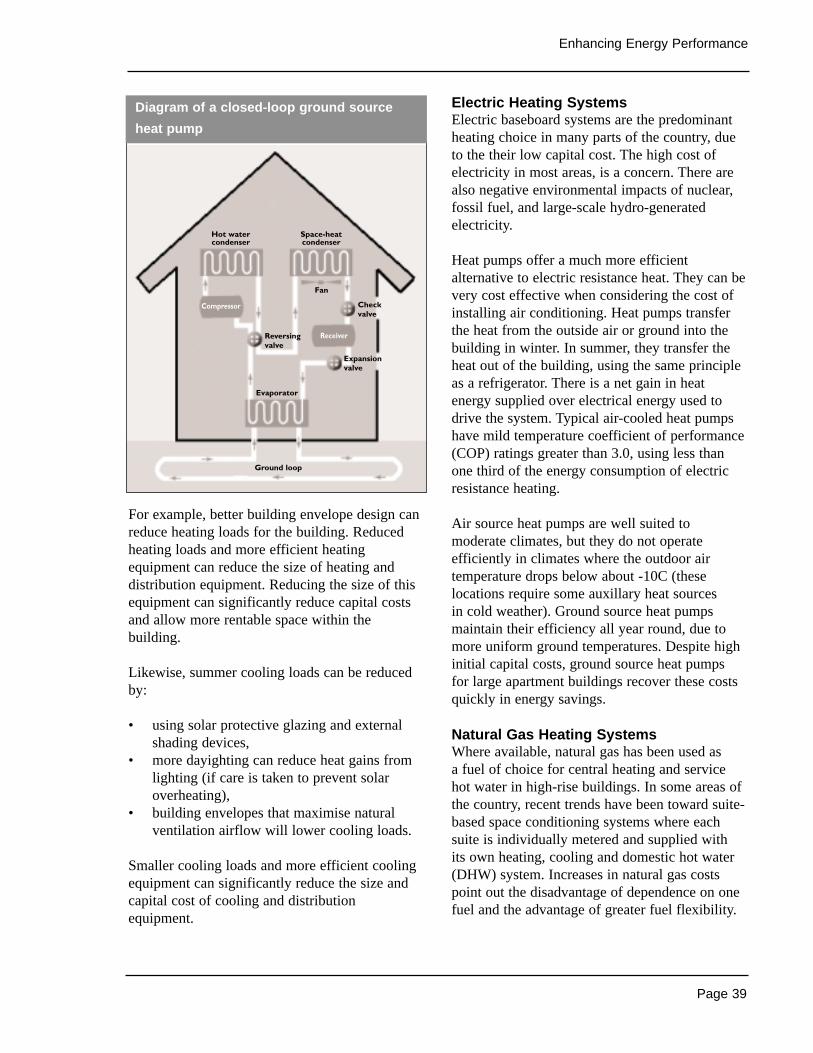
Page 39
Enhancing Energy Performance
For example, better building envelope design canreduce heating loads for the building. Reducedheating loads and more efficient heatingequipment can reduce the size of heating anddistribution equipment. Reducing the size of thisequipment can significantly reduce capital costsand allow more rentable space within thebuilding.
Likewise, summer cooling loads can be reducedby:
• using solar protective glazing and externalshading devices,
• more dayighting can reduce heat gains fromlighting (if care is taken to prevent solaroverheating),
• building envelopes that maximise naturalventilation airflow will lower cooling loads.
Smaller cooling loads and more efficient coolingequipment can significantly reduce the size andcapital cost of cooling and distributionequipment.
Electric Heating SystemsElectric baseboard systems are the predominantheating choice in many parts of the country, dueto the their low capital cost. The high cost ofelectricity in most areas, is a concern. There arealso negative environmental impacts of nuclear,fossil fuel, and large-scale hydro-generatedelectricity.
Heat pumps offer a much more efficientalternative to electric resistance heat. They can bevery cost effective when considering the cost ofinstalling air conditioning. Heat pumps transferthe heat from the outside air or ground into thebuilding in winter. In summer, they transfer theheat out of the building, using the same principleas a refrigerator. There is a net gain in heatenergy supplied over electrical energy used todrive the system. Typical air-cooled heat pumpshave mild temperature coefficient of performance(COP) ratings greater than 3.0, using less thanone third of the energy consumption of electricresistance heating.
Air source heat pumps are well suited tomoderate climates, but they do not operateefficiently in climates where the outdoor airtemperature drops below about -10C (theselocations require some auxillary heat sources in cold weather). Ground source heat pumpsmaintain their efficiency all year round, due tomore uniform ground temperatures. Despite highinitial capital costs, ground source heat pumps for large apartment buildings recover these costsquickly in energy savings.
Natural Gas Heating SystemsWhere available, natural gas has been used as a fuel of choice for central heating and servicehot water in high-rise buildings. In some areas ofthe country, recent trends have been toward suite-based space conditioning systems where eachsuite is individually metered and supplied with its own heating, cooling and domestic hot water(DHW) system. Increases in natural gas costspoint out the disadvantage of dependence on onefuel and the advantage of greater fuel flexibility.
Diagram of a closed-loop ground source
heat pump
Hot watercondenser
Space-heatcondenser
Fan
Evaporator
Ground loop
Compressor
Receiver
Checkvalve
Expansionvalve
Reversingvalve

Page 40
Healthy High-Rise
Integrated space heating and DHW systems can bemore energy efficient than individual space heatand DHW systems. They become more suitablewhen heating/cooling loads of suites are reducedthrough improved integrated building design.
The efficiency of central systems continues toimprove. High efficiency boilers are readilyavailable and have a proven track record ofoperating efficiently (as high as 92% forcondensing gas boilers). Increasingly, designersare specifying a multiple boiler system for abetter matching of the required load to thecapacity of the equipment.
HVAC Distribution SystemsHVAC systems can be central or modular indesign. Central systems, such as 2 or 4 pipehydronic systems, have centralised heating andcooling equipment with local fan coil or otherdistribution units in each suite. Modular systemshave heating and cooling equipment locatedwithin each suite e.g. heat pumps in each suite.
Both have their advantages and disadvantages.Modular systems provide greater independence of individual suites, and energy consumption iseasier to meter. Central systems can reduceenergy costs by using improved micro-processorcontrols, variable speed drives, and energymanagement control systems. They also providegreater fuel flexibility, have a centralised point ofmaintenance, and allow greater control bybuilding management.
RETROFIT OPPORTUNITIES
The energy consumption and costs of operatingheating and cooling equipment can be reducedwith retrofit measures that improve the efficiencyof existing equipment, replace equipment withnew high efficiency equipment, or involve fuelswitching. The payback period for retrofitmeasures will be reduced when equipment ismodified during routine maintenance or replacedwith high efficiency equipment during majorrenovation projects or when the equipment isbeing replaced at the end of its useful life.
1 Replace gas fired boilers with high efficiencyunits–Replacement gas fired boilers areavailable with Annual Fuel UtilizationEfficiencies (AFUE) greater than 90%compared to 65% for older naturallyaspirating units.
2 Insulate boilers and hot water heating pipingto reduce heat losses and improve heatdelivery to suites.
3 Seal and insulate warm air ducts in unheatedspaces such as in the roof, rooftop penthouse,or unheated garages.
4 Calibrate the hot water reset temperaturecontroller in buildings with hot water heating–Controllers that reset the water temperatureupward as the outdoor temperature fallsshould be calibrated so that the systemtemperature is just hot enough to meetheating requirements.
5 Replace or resize boiler make-up grilles toimprove combustion or dilution airflow inatmospherically vented boilers.
6 Install timeclocks to reduce operation of localexhaust fans in laundry, recreation, andstorage rooms. The times that local exhaustfan operation should be matched to the usagepatterns of the space.
7 Reduce heated garage temperature - Theoperating temperature of heated garagesshould be reduced to 5°C. Thermostats mayhave to be replaced if they do not have arange of temperature control as low as 5°C. If garage temperatures are maintained atelevated levels to avoid freezing pipes andcold floors above the garage, insulation andself regulating tracing cable can solve theseproblems for a fraction of the cost of energyto heat the garage.
Page 41
Enhancing Energy Performance
8 Shut down ventilation fans serving unusedgarage areas to reduce fan energy and heatingrequirements for makeup air. Do not switchoff exhaust fans on the lowest level of multilevel garages since carbon monoxide collectsthere because it is heavier than air.
9 Convert from higher cost heating fuel tolower cost fuel - The most typical conversionis from electricity or oil to natural gas, withwork performed during replacement orupgrading of heating equipment.
10 Indoor swimming pool dehumidification–Installation of a dehumidification system onexisting heating and ventilation systems willremove heat and moisture from the air andreturn it to the pool or enclosure. Much lowerexhaust rates can then be used to preventmoisture damage to the pool enclosure. Poolenclosure heating and water heatingrequirements are both significantly reduced.
Sources of Information
• Mechanical and Electrical Systems inApartments and Multi-Suite Buildings, A Practitioners Guide, CMHC, 1999.
• The High-Rise Residential ConstructionGuide 1995, Ontario New Home WarrantyProgram.
• Energy And Water Efficiency in Multi-UnitResidential Buildings, Technical Manual,CMHC, 2000. Tip of the Week @www.cmhc-schl.gc.ca/en/imquaf/himu/himu/indexw.cfm
• Fundamentals, American Society of HeatingRefigerating and Air Conditioning EngineersInc. (ASHRAE).
• ASHRAE Standard 90.1-1999, EnergyStandard for Buildings Except Low-RiseResidential Buildings, American Society ofHeating Refigerating and Air ConditioningEngineers Inc. (ASHRAE)
• Model National Energy Code for Buildings,National Research Council of Canada.
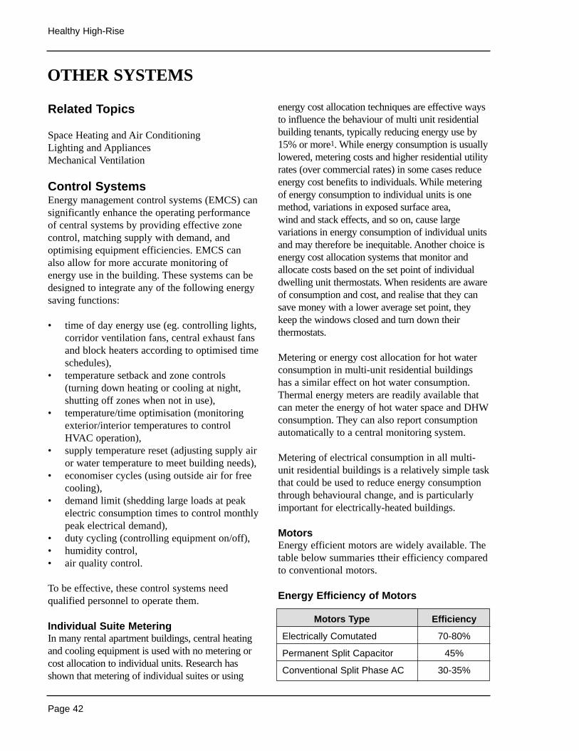
energy cost allocation techniques are effective waysto influence the behaviour of multi unit residentialbuilding tenants, typically reducing energy use by15% or more1. While energy consumption is usuallylowered, metering costs and higher residential utilityrates (over commercial rates) in some cases reduceenergy cost benefits to individuals. While meteringof energy consumption to individual units is onemethod, variations in exposed surface area, wind and stack effects, and so on, cause largevariations in energy consumption of individual unitsand may therefore be inequitable. Another choice isenergy cost allocation systems that monitor andallocate costs based on the set point of individualdwelling unit thermostats. When residents are awareof consumption and cost, and realise that they cansave money with a lower average set point, theykeep the windows closed and turn down theirthermostats.
Metering or energy cost allocation for hot waterconsumption in multi-unit residential buildingshas a similar effect on hot water consumption.Thermal energy meters are readily available thatcan meter the energy of hot water space and DHWconsumption. They can also report consumptionautomatically to a central monitoring system.
Metering of electrical consumption in all multi-unit residential buildings is a relatively simple taskthat could be used to reduce energy consumptionthrough behavioural change, and is particularlyimportant for electrically-heated buildings.
MotorsEnergy efficient motors are widely available. Thetable below summaries ttheir efficiency comparedto conventional motors.
Energy Efficiency of Motors
Page 42
Healthy High-Rise
Related Topics
Space Heating and Air ConditioningLighting and AppliancesMechanical Ventilation
Control SystemsEnergy management control systems (EMCS) cansignificantly enhance the operating performanceof central systems by providing effective zonecontrol, matching supply with demand, andoptimising equipment efficiencies. EMCS canalso allow for more accurate monitoring ofenergy use in the building. These systems can bedesigned to integrate any of the following energysaving functions:
• time of day energy use (eg. controlling lights,corridor ventilation fans, central exhaust fansand block heaters according to optimised timeschedules),
• temperature setback and zone controls(turning down heating or cooling at night,shutting off zones when not in use),
• temperature/time optimisation (monitoringexterior/interior temperatures to controlHVAC operation),
• supply temperature reset (adjusting supply airor water temperature to meet building needs),
• economiser cycles (using outside air for freecooling),
• demand limit (shedding large loads at peakelectric consumption times to control monthlypeak electrical demand),
• duty cycling (controlling equipment on/off),• humidity control,• air quality control.
To be effective, these control systems needqualified personnel to operate them.
Individual Suite MeteringIn many rental apartment buildings, central heatingand cooling equipment is used with no metering orcost allocation to individual units. Research hasshown that metering of individual suites or using
OTHER SYSTEMS
Motors Type Efficiency
Electrically Comutated 70-80%
Permanent Split Capacitor 45%
Conventional Split Phase AC 30-35%
Page 43
Enhancing Energy Performance
Pumps and fans that have long run times or areoperated continuously for water circulation orventilation should always use high efficiency motors.Equipment that runs during both heating and coolingseasons will also benefit greatly from high efficiencymotors. Variable speed drives for pumps and fanscan reduce energy consumption by as much as35%when compared to single speed systems.
While elevators are not a major contributor to energyuse in a high-rise building, significant improvementsare available. More efficient motors and controlsystems can reduce their total consumption by 40%.Technologies are also available that place the motorswithin the elevator shaft, eliminating the requirementfor a mechanical penthouse and their the associatedair-leakage problems.
Auxiliary Electric HeatersGarage ramp heaters and exterior block heaters arelarge energy users. Snow/ice and temperaturesensing controls should be used on garage rampheaters to ensure that they only operate whenrequired. Snow melting, using sub-slab piped hotwater from boilers, can be much more cost effectiveand reliable than electric resistance heaters. A betteralternative would be level access or covered rampsso that ramp heaters are not needed.
Timers and thermostat controls can reduce energyuse by block heaters. Thermostats should controlblock heaters so that they only operate attemperatures below -9°C. Since block heaters areonly needed for 3 to 4 hours before the vehicle isstarted, timers can be set for block heaters to startas required by tenants.
Domestic Hot WaterDomestic hot water (DHW) energy use can bereduced through installation of low flow showerand sink fixtures. Low flow showerheads rated at9.5 l/min and kitchen and bathroom aerators ratedat 8.35 l/min are inexpensive and have very highconsumer acceptance. An additional benefit isthat hot water tanks and equipment can bereduced in size and cost. Other measures canreduce DHW energy consumption. Completeinsulation of storage tanks and hot water pipingwill reduce heating energy costs.
Heat losses from DHW storage tanks and piping canalso be reduced by adding a set back feature toreduce hot water temperature to a minimum ofapproximately 46°C during the night time. Heat trapson inlet and outlet pipes also reduce heat losses.
Controls are available that match booster pumpoperation and water supply pressure to actualdemand. Booster pump power consumption isthus reduced, while control of hot water pressurelowers hot water consumption. Significant energysavings can also be had from adding controls thatshut down DHW recirculation pumps whendemand is low (at night).
Hot water pre-heating can also be provided bycondenser heat from chillers, heat recovery fromgrey water, and/or solar heating systems. Energysavings of 50% are achievable by combining heatrecovery with water conservation strategies.
Major hot water savings are possible in buildingswith common laundry facilities. Washing machinecontrol cycles can be modified to allow coldrinsing only. Using water efficient horizontal axismachines reduces hot water use significantly andalso has the advantage of reducing dryer energyrequirements.
1 Hewett et al, Heating Cost Allocation in Multi-familyBuildings: Energy Savings and Implementation Standards,ASHRAE Transactions 95 (1), 1989.
RETROFIT OPPORTUNITIES
Energy consumption and cost can be reducedthrough a number of control system, suitemetering, motor, auxiliary heater and domestic hotwater retrofit opportunities. These can be carriedout during renovation or equipment replacementor maintenance.
Control Systems1 Installing energy management control systems
that control peak electrical demand. Possiblemeasures range from the installation of simpletimeclocks that shut off non essential loads attimes of peak demand to microprocessorcontrol systems that control all sheddableloads in response to electrical demand.
Page 44
Healthy High-Rise
2 Installing setback thermostats in individualsuites to reduce night time heating energyconsumption
3 Installing individual suite metering or energycost allocation systems in individual suites
Motors4 Replacing worn out electric motors with high
efficiency electrically commutated orpermanent split capacitor motors. Largeelectric fan and pump drive motors that haverun long times are the most important motorsto target for replacement.
Electric Heaters5 Adding snow/ice and temperature controls
to garage ramp heaters.
6 Adding thermostatic and timer controls toblock heaters.
Domestic Hot Water7 Installing flow restrictors on existing
showerheads and faucets.
8 Replacing existing compression type tapswith washerless type taps to reduce energyconsumption associated with hot water leaks.
9 Adding insulation to existing DHW tanks andaccessible distribution piping.
10 Adding heat traps to all DHW storage tankinlet and outlet piping.
11 Reducing hot water temperature to reduceheat losses from storage tanks and piping.The temperature in storage tanks should bereduced to the lowest level satisfactory to alltenants but not below approximately 49°C forsafety reasons due to the growth of bacteria atlower temperatures.
12 Installing a mechanical timeclock on the hotwater temperature controller of central DHWsystems to reduce night time hot watertemperature to a minimum of approximately46°C.
13 Reducing DHW pressure at the top floor toreduce booster pump energy consumption. Aminimum pressure of approximately 170 kPa(25 psi) during times of maximum demand isconsidered acceptable.
14 Installing timeclocks to shut down recirculationpumps during times of little or no use to reducerecirculation pump energy consumption andheat losses through poorly insulated piping.Recirculation pumps are typically shut offbetween 11:00 p.m. and 7:00 am.
15 Upgrading controls for multiple boilers toensure that the first boiler is fully loadedbefore the next boiler fires, ensuringoptimised system efficiencies.
Sources of Information
• The High-Rise Residential Construction Guide1995, Ontario New Home Warranty Program.
• Energy And Water Efficiency in Multi-UnitResidential Buildings, Technical Manual,CMHC, 2000.
• HVAC Controls and Systems, Levenhagen,J.I., Spethmann, D.H., McGraw Hill, NewYork, 1992.
• HVAC Systems and Equipment Handbook,American Society of Heating Refigerating andAir Conditioning Engineers Inc. (ASHRAE)
• ASHRAE Standard 90.1-1999, EnergyStandard for Buildings Except Low-RiseResidential Buildings, American Society ofHeating Refigerating and Air ConditioningEngineers Inc. (ASHRAE)
• Directory of Water Conserving PlumbingFixtures, International Association ofPlumbing and Mechanical Officials, 1997. @ http://ww.iapmo.org
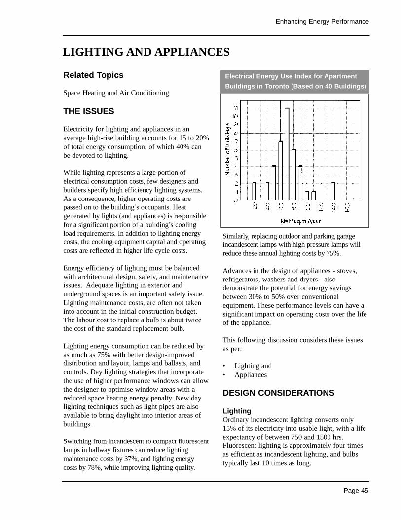
Page 45
Enhancing Energy Performance
Related Topics
Space Heating and Air Conditioning
THE ISSUES
Electricity for lighting and appliances in anaverage high-rise building accounts for 15 to 20%of total energy consumption, of which 40% canbe devoted to lighting.
While lighting represents a large portion ofelectrical consumption costs, few designers andbuilders specify high efficiency lighting systems.As a consequence, higher operating costs arepassed on to the building’s occupants. Heatgenerated by lights (and appliances) is responsiblefor a significant portion of a building’s coolingload requirements. In addition to lighting energycosts, the cooling equipment capital and operatingcosts are reflected in higher life cycle costs.
Energy efficiency of lighting must be balancedwith architectural design, safety, and maintenanceissues. Adequate lighting in exterior andunderground spaces is an important safety issue.Lighting maintenance costs, are often not takeninto account in the initial construction budget.The labour cost to replace a bulb is about twicethe cost of the standard replacement bulb.
Lighting energy consumption can be reduced byas much as 75% with better design-improveddistribution and layout, lamps and ballasts, andcontrols. Day lighting strategies that incorporatethe use of higher performance windows can allowthe designer to optimise window areas with areduced space heating energy penalty. New daylighting techniques such as light pipes are alsoavailable to bring daylight into interior areas ofbuildings.
Switching from incandescent to compact fluorescentlamps in hallway fixtures can reduce lightingmaintenance costs by 37%, and lighting energycosts by 78%, while improving lighting quality.
Similarly, replacing outdoor and parking garageincandescent lamps with high pressure lamps willreduce these annual lighting costs by 75%.
Advances in the design of appliances - stoves,refrigerators, washers and dryers - alsodemonstrate the potential for energy savingsbetween 30% to 50% over conventionalequipment. These performance levels can have asignificant impact on operating costs over the lifeof the appliance.
This following discussion considers these issuesas per:
• Lighting and• Appliances
DESIGN CONSIDERATIONS
LightingOrdinary incandescent lighting converts only 15% of its electricity into usable light, with a lifeexpectancy of between 750 and 1500 hrs.Fluorescent lighting is approximately four timesas efficient as incandescent lighting, and bulbstypically last 10 times as long.
LIGHTING AND APPLIANCES
Electrical Energy Use Index for Apartment
Buildings in Toronto (Based on 40 Buildings)
Page 46
Healthy High-Rise
Standard fluorescent lighting systems withelectronic ballasts are a suitable choice for manycommon area uses. Higher performance fluorescentlamps, called T8’s or T5’s, deliver higher lightoutput and better light quality, with lower energyinput. Compact fluorescent lamps can replaceincandescent lamps using the same lamp fixtures.While costing more than incandescent bulbs,compact fluorescents have longer life and betterenergy performance, providing a rapid payback oftheir increased initial cost.
A number of advanced incandescent lights arealso available. While less efficient thanfluorescent lighting, they consume less energythan standard incandescent light bulbs and lastlonger. Halogen gas filled lamps can reduceenergy consumption by 50% and last up to 250%as long as standard incandescent light bulbs.
Parabolic-aluminized reflector (PAR) bulbs lastlonger and can also reduce energy consumption.Standard PAR bulbs have longer life advantages,lasting up to 2000 hrs. “Energy Saving”,“Halogen”, and “IR” PAR bulbs have the sameextended life expectancy but consume 20%, 40%,and 60% less energy respectively than standardincandescents.
High pressure sodium and metal halide lamps areefficient options for outdoor and garage lighting.High pressure sodium lighting is the mostefficient high intensity discharge lightingavailable, using 75% to 80% less energy thanstandard lighting units and lasting for 18,000 to24,000 hrs. Although they provide excellentcontrast making them good for street and securitylighting, their colour rendering is poor. Metalhalide units are an efficient option when a whiterlight with better colour rendering is required.
Electronic ballasts consume less energy thanelectromagnetic ballasts and also increase theefficiency of fluorescent lamps. Combined ballastand bulb efficiency increases are typically in therange of 20% to 35%. Dimmable electronicballasts are available that can reduce energy usethrough dimming lights, without the losses inefficiency inherent in non-electronic ballasts.
Specular reflectors are another low cost option for increasing the light output from fixtures.
New emergency lighting systems include lightemitting diode (LED) technologies, whichtypically reduce energy consumption toapproximately 2 Watts from 15 to 25 Watts forincandescent lamps. They also have much longerlife, reducing both energy and maintenance costs.
Proper lighting layout and design cansignificantly reduce the number of light fixturesrequired. Fewer fixtures save capital, operating,and maintenance costs.
Daylighting, combined with timers, motion sensors,and photocell controls for shutting off interior lights(when they are not required) can reduce energy usesignificantly. European experience with timercontrols and motion sensor lighting systemsdemonstrates a more efficient use of lighting energyin parking areas, garages, corridors and stairwells,without sacrificing occupant security.
AppliancesMajor home appliances may be provided by the builder. The energy efficiency of majorappliances has improved significantly over thelast decade, and minimum efficiency levels areregulated by the federal government. However,specification of higher performing models canresult in savings of up to 50% in energy use.
Appliances are manufactured are rated accordingto Natural Resources Canada’s EnerGuide energyrating system. EnerGuide appliance energyconsumption ratings are published to assist in the selection of appliances.
Front loading horizontal axis washing machinesthat use between 35 to 45% less water and 60%less energy than top loading vertical axis washingmachines. They typically cost about one thirdmore than conventional units. They also reducedrying time and therefore lower energyconsumption for dryers. Maintenance is reducedbecause they are simpler in design. They alsoincrease accessibility for the elderly and peoplewith handicaps.
Page 47
Enhancing Energy Performance
RETROFIT OPPORTUNITIES
Lamps and ballasts can be replaced with moreefficient models during routine bulb replacementas long as the ballasts are matched to the lamptype. During renovation or retrofit, lamps, ballastsand fixtures can be upgraded to provide more lightof better quality using less energy. Appliances canalso be upgraded one at a time with more efficientmodels during replacement at the end of theiruseful lives, or all at the same time as a retrofitmeasure. Some retrofit opportunities include:
Lighting1 Reduce common area incandescent lighting
levels. While common area lighting isprovided for safety and security, in manybuildings the number and wattage ofincandescent bulbs can be reduced whilemaintaining acceptable light levels.
2 Replace indoor incandescent bulbs withcompact fluorescent bulbs during routine bulbreplacement. Incandescent screw-in lamps incorridors, lobbies, stairwells, laundry rooms,and other common areas can be replaceddirectly in many cases with screw in compactfluorescent bulbs. These lamps can also beused in fixtures in dwelling units.
3 Replace incandescent lighting with highefficiency fluorescent fixtures in commonareas and in kitchens and bathrooms of rentalsuites. Common area lighting can beretrofitted at any time with minimaldisturbance to tenants. Kitchen and bathroomlighting retrofits are best performed as suitesare being renovated.
4 Replace incandescent lamps in exit signs withLED lamps.
5 Replace outdoor and parking garageincandescent lighting with high pressuresodium fixtures.
6 Install timeclocks and/or photocell control onoutdoor lights to turn them off during thedaylight hours.
Appliances7 Modify washing machine control cycles so
that only cold rinses are used on all cycles toreduce hot water energy consumption.
Sources of Information
• IES Lighting Handbook, 8th Edition,Illuminating Engineering Society, 1993.
• ASHRAE Standard 90.1-1999, EnergyStandard for Buildings Except Low-RiseResidential Buildings, American Society ofHeating Refigerating and Air ConditioningEngineers Inc. (ASHRAE)
• 2000 Energuide Appliance Directory, NaturalResources Canada, 1-800-387-2000. @http://energuide.nrcan.gc.ca/
• Energy Efficient Lighting Products for Your Home, Natural Resources Canada, 1-800-387-2000.
• Consumer’s Guide to Buying and UsingEnergy Efficient Household Appliances,Natural Resources Canada, 1-800-387-2000.
• Product Knowledge Guides, Contact LocalProvincial Electric Utility
Page 48
Healthy High-Rise
Related Topics
Building EnvelopeSpace Heating and Air ConditioningMechanical VentilationSite Planning
THE ISSUES
While improving the end-use energy efficiency of high rise residential buildings is one methodfor reducing GHG emissions and other negativeimpacts of energy use, another is to use on siteenergy supply systems that are higher inefficiency or that make use of renewable energysources that are low in GHG emissions and othernegative environmental impacts. Renewableenergy supply systems that use solar, wind,hydro, biomass and geothermal energy, as well as on-site co-generation and fuel cell technologiesthat make greater use of conventional fuel sourcescan deliver energy to the building with lowerGHG emissions and other environmental impacts.
Strong advances have been made in developinghigh efficiency on-site energy generation andrenewable energy technologies in the last twodecades, including lower costs, higherefficiencies, improved quality and increasedreliability, making their applications moreattractive now than in the past.
The alternative systems considered here are:
• Co-generation• Ground Source Heat Pumps• Fuel Cells• Solar Energy• Daylighting• Passive Cooling• Wind Turbines
DESIGN CONSIDERATIONS
Co-generationOn-site co-generation is a highly efficient meansof generating both heat and electric power at thesame time from the same energy source. Microco-generation systems appropriate to theindividual high rise residential building level haveexcellent future prospects. In regions supplied by fossil fuel generated electricity, on-site co-generation systems can displace systems whichgenerate electricity at 33% efficiency, withnatural gas fired co-generation systems. Thesenew co-generation systems generate bothelectricity and heat energy with combinedefficiencies in the order of 80% to 90%,significantly reducing the GHG emissionsassociated with each unit of energy delivered.
Co-gen systems can provide electricity as well as heat for space and water heating in winter, andthe waste heat can be used through absorptioncooling to provide cooling in the summer. Theycan also be grid- connected to sell electricity backto the grid when extra capacity is available andwhere permitted by regulations.
These systems are more complex than equipmenttypically found in high rise residential buildingsand require a turnkey operation or servicecontract approach.
Ground Source Heat PumpsGround source heat pump (GSHP) systems1
utilise the heat from renewable solar energystored in the ground (or water). GSHP systemsare being installed in considerable numbers in a number of countries to provide space heatingand/or cooling and hot water heating. They are an efficient means for providing space heatingand cooling for buildings in Canada, and unlikeair source heat pumps they remain efficient incold climates.
ALTERNATIVE ENERGY SUPPLY SYSTEMS
Page 49
Enhancing Energy Performance
GSHP units sold in Canada must exceed a COP of 3.0, resulting in 1/3 or less electricityconsumed than with the use of electric resistanceheating. Systems are designed as either closed-loop or open-loop systems. Closed-loop systemshave closed piping systems installed in horizontaltrenches, vertical bore holes, or lake bottoms,through which water or an antifreeze solution iscirculated from an indoor heat pump. Open- loopsystems use water from a lake or well that ispumped though the heat pump on a once-throughbasis. An optional de-superheater on the heatpump can provide water heating at much higherefficiencies than conventional hot water heatingtechnology. Ground-source heat pumps are moreexpensive to install than gas, oil or electric heatingunits, but are more economical on a multi-unitbasis, and typically demonstrate excellent lifecycle costs when compared to conventionalcombination heating/cooling systems.
Fuel CellsFuel cells capable of providing all the electricneeds of the average home are presently in thedevelopment stage, and may be on the verge ofbreakthrough as an economical alternative totraditional energy sources. Fuel cells convert theenergy of fuel (hydrogen, natural gas, methanol,gasoline, etc) into electricity through anelectrochemical process, without producingcombustion emissions such as particulates, carbonmonoxide, or nitrogen or sulphur oxides. Fuelcells running on hydrogen derived from renewablesources produce no CO2 emissions. They can alsorun on other fuels, and generate less CO2 thanfossil fuel generated electricity due to higherefficiency levels. This advantage is furtherenhanced with recovery of excess heat fordomestic hot water or space heating, in which caseefficiencies of up to 70%-85% can be achieved.
Solar EnergyOff-the-shelf solar heating and electrical systemsare readily available for pool heating, DHWheating, ventilation air heating, and photovoltaicapplications.
Active Solar Pool HeatersThe most cost effective solar hot water heatingsystems on the market are solar pool heaters.Simple, inexpensive, unglazed black plastic solarcollector systems are readily available that canprovide all of the heating needs for residentialmulti-family outdoor swimming pools fromspring until fall, eliminating both fossil fuelconsumption and capital costs of conventionalheating equipment. The systems are simple toinstall, and generally have 3- to 6-year simplepayback periods.
Active Solar Domestic Hot Water (DHW)Heaters
Various active solar domestic hot water heatingsystems are available that vary in complexity,efficiency, and cost. Modern solar water heatersare now relatively easy to maintain, and can payfor themselves with energy savings over theirlifetime. An efficient flat-plate solar hot waterheater can collect approximately 2GJ/m2 ofcollector area per year of energy in most ofsouthern Canada. Other systems available includethermo-siphon systems that eliminate the need forpumps, which are common in Southern Europe.Evacuated tube collectors are more efficient, butalso more expensive, with longer paybackperiods.
Active Solar Ventilation Air Heating A technique available for reducing the energyrequired to heat ventilation air is to use solarenergy to directly preheat the air drawn into thebuilding. Commercially available systems of thistype typically use a dark coloured perforatedaluminium sheet mounted on a south-facing wall.As the sun heats the sheet, a fan draws solarheated air through the perforations. Thispreheating can significantly reduce the energyneeded to bring fresh air up to room temperature.NRCan and Conserval Engineering aredeveloping a new residential “Solarwall” thatincorporates heat recovery ventilation.
PhotovoltaicsSince 1980 the price of PV modules has droppedby approximately 80 percent, and there iscurrently a world-wide boom in PV sales, muchof which is driven by government support for
Page 50
Healthy High-Rise
solar home systems in a number of countries. Anumber of technological advances and utilitychanges are making PV systems more attractive.One change is the availability of solar cellsintegrated into roofing shingles, tiles, and windowglass. PV system costs are reduced by eliminatingthe cost of the roofing or window materialsreplaced by solar panels. Another change is theuse of net metering, where the systems areconnected to the grid, and utilities purchase theexcess electricity generated, ideally at the sameprice that they sell electricity for. Battery storagesystems and controls can be eliminated,substantially reducing costs.
Passive Solar Heating Passive solar techniques collect thermal energyfrom direct sunlight, store the collected energy in the thermal mass of the building elements orother storage, and release it back into the interiorof the building as required. Improved windowtechnologies allow designers to increase solargains to apartment buildings without the normallyassociated increase in heating load. The benefitsof using passive solar techniques includesimplicity, price, and the design elegance offulfilling one’s needs with materials at hand.
DaylightingA related solar concept is daylighting design,which optimises the use of natural daylight. Use oflight shelves and clerestory windows are twomethods by which sunlight can be directed furtherinto the interior of a room. They provide a moreuniform level of illumination, whilesimultaneously reducing the building’s coolingload due to heat gains from lighting. Fullintegration of natural and artificial lighting requirescareful design and sophisticated lighting controls.
Passive CoolingIn cooler parts of Canada the need for air-conditioning in homes can be greatly reduced oreven eliminated by using passive cooling designs.In hotter climates passive cooling techniques canreduce energy used for cooling during shoulderseasons. The terms passive cooling or naturalcooling apply to various simple coolingtechniques that enable the indoor temperature of
buildings to be lowered through the use of naturalenergy sources. Usually the cold collecting andstorage elements are an integral part of thebuilding itself - such as the building envelope orstructure, or the soil under the building. Forremoving heat from a building, natural coolinguses natural heat sinks such as ambient air, theupper atmosphere (radiation to the night air),water, or soil.
There are many different natural coolingtechniques available to designers. Theapplicability of each technique varies greatly byclimate, and therefore location, within the country.These techniques or systems can be classifiedaccording to the following broad categories:
• Comfort Ventilation - improving comfort whenthe indoor temperature is too warm by usingnatural ventilation to increase airflow of cooleroutside air. The potential for cross-ventilationand stack ventilation strategies are oftenlimited due to fire/smoke concerns in multi-unit buildings. However, proper design andplacement of windows can increase airflowrates through windows on a single side of asuite, or increase cross-ventilation airflowthrough adjacent walls in corner suites.
• Nocturnal Ventilative Cooling - utilising ahigh thermal mass building which is cooled atnight by circulating cool night air through thebuilding or high thermal mass structures.
• Radiant Cooling - using the roof of abuilding, a heat storage mass on the roof, orlightweight radiators to cool the building atnight. Surfaces will transfer heat to the skythrough radiation at night.
• Evaporative Cooling - adding water to the air(such as with cooling towers) to reduce theair temperature in a process called adiabaticcooling. The cooled air is then circulated intothe building, Another technique that usesevaporative cooling is to cool the roof of thebuilding with a pond whose water evaporatesto the outside air. These techniques are onlyeffective in arid climates.

Page 51
Enhancing Energy Performance
• Soil Cooling–circulating air or water throughpipes in the soil where it is cooled.
For all passive cooling designs, solar and internalheat gains should be minimised through shadingand proper daylighting design to optimise the useof natural daylight and reduce cooling loads.Other techniques that use vegetation andlandscaping to aid natural cooling are found inthe landscaping section of this document.
Wind TurbinesWind power is rapidly expanding as a renewableenergy source, particularly at the utility scalelevel. In the last decade costs for wind-generatedelectricity have dropped from 30¢ per kilowatt-hour to 7¢ per kilowatt-hour. Wind generatedelectricity may be practical on an individualbuilding level under favourable site situations.
1 Ground source heat pump systems are referred to undermany names including geothermal, geo-exchange, earth-coupled, water-coupled, groundwater, ground-coupled, andwater-source heat pump systems.
Sources of Information
• Natural Ventilation in Non DomesticBuildings, Applications Manual, CIBSE,1997.
• Daylighting: Design and Analysis, Robbins,CL., Van Nostrand Reinhold, New York,1986.
• Solar Energy Society of Canada Inc. @ http://www.solarenergysociety.ca/
• CANMET Energy Diversification ResearchLaboratory (CEDRL) of Natural ResourcesCanada @ http://cedrl.mets.nrcan.gc.ca/e/index_e.html
• RETScreen Renewable Energy ProjectAnalysis Software, CANMET EnergyDiversification Research Laboratory(CEDRL) of Natural Resources Canada @ http://retscreen.gc.ca/
• Canadian Earth Energy Association @ http://www.earthenergy.org/
• The Canadian Wind Energy Association @ http://www.canwea.ca/
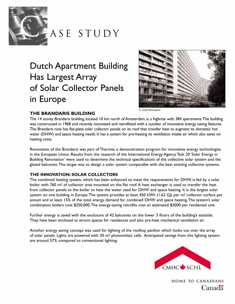
A S E S T U D YcDutch Apartment BuildingHas Largest Array of Solar Collector Panels in EuropeTHE BRANDARIS BUILDINGThe 14 storey Brandaris building, located 10 km north of Amsterdam, is a highrise with 384 apartments.The buildingwas constructed in 1968 and recently renovated and retrofitted with a number of innovative energy saving features.The Brandaris now has flat-plate solar collector panels on its roof that transfer heat to augment its dometsic hotwater (DHW) and space heating needs. It has a system for pre-heating its ventilation intake air which also saves onheating costs.
Renovation of the Brandaris was part of Thermie, a demonstration program for innovative energy technologiesin the European Union. Results from the research of the International Energy Agency Task 20 ‘Solar Energy inBuilding Renovation’ were used to determine the technical specifications of the collective solar system and theglazed balconies.The target was to design a solar system comparable with the best existing collective systems.
THE INNOVATION: SOLAR COLLECTORSThe combined heating system, which has been enhanced to meet the requirements for DHW, is fed by a solarboiler with 760 m2 of collector area mounted on the flat roof.A heat exchanger is used to transfer the heatfrom collector panels to the boiler to heat the water used for DHW and space heating. It is the largest solarsystem on one building in Europe.The system provides at least 450 kWh (1.62 GJ) per m2 collector surface perannum and at least 15% of the total energy demand for combined DHW and space heating.The system’s solarcombination boilers cost $250,000.The energy-saving retrofits cost an estimated $3000 per residential unit.
Further energy is saved with the enclosure of 42 balconies on the lower 3 floors of the building’s eastside.They have been enclosed as atrium spaces for residences and also pre-heat mechanical ventilation air.
Another energy saving concept was used for lighting of the rooftop pavilion which looks out over the array of solar panels. Lights are powered with 30 m2 photovoltaic cells. Anticipated savings from this lighting systemare around 57% compared to conventional lighting.
© Joost Brouwers
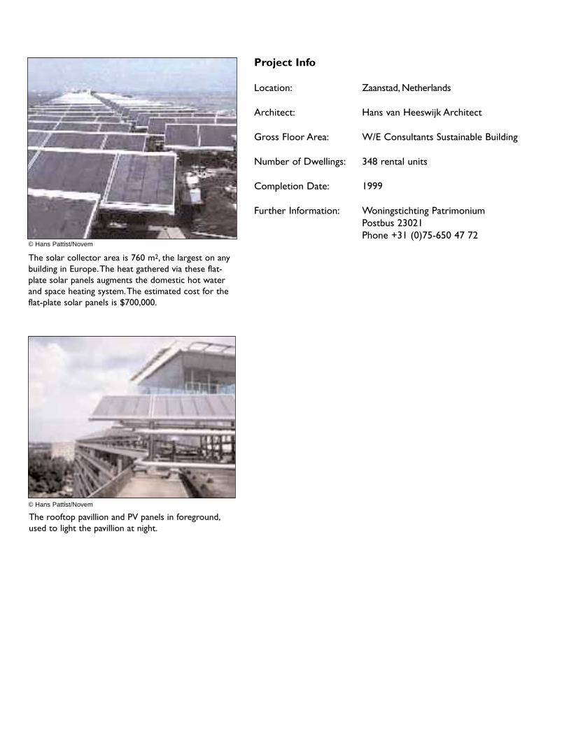
The solar collector area is 760 m2, the largest on anybuilding in Europe.The heat gathered via these flat-plate solar panels augments the domestic hot waterand space heating system.The estimated cost for theflat-plate solar panels is $700,000.
The rooftop pavillion and PV panels in foreground,used to light the pavillion at night.
© Hans Pattist/Novem
© Hans Pattist/Novem
Project Info
Location: Zaanstad, Netherlands
Architect: Hans van Heeswijk Architect
Gross Floor Area: W/E Consultants Sustainable Building
Number of Dwellings: 348 rental units
Completion Date: 1999
Further Information: Woningstichting PatrimoniumPostbus 23021Phone +31 (0)75-650 47 72

A S E S T U D YcBoston Highrise RetrofitCuts Energy Costs by 15-percent
THE MARGOLISThe Margolis is a 12-storey apartment building in Chelsea,Massachusetts, a suburb of Boston.The 150-unit buildingneeded retrofit work as utility bills increased while occupantcomfort decreased. From 1992 to 1996 it was the site of a joint study by the U.S. Department of Energy (DOE),the Department of Housing and Urban Development (HUD), the Boston Edison Company, and the ChelseaHousing Authority to analyze ventilation and airflow and the resulting energy costs.A series of ventilation and air-leakage measurements were made using tracer gases and blower doors. Following this, building airflow wasmodelled. Modelling showed that even apartments on the windward side of the building did not receive sufficientoutside air (according to ASHRAE standard 62) during periods of low windspeed. High winds combined with coldwinter temperatures magnified infiltration, conduction and interior air-flow problems throughout the building.Windward facing tenants responded by elevating baseboard settings over 26°C (80°F), while leeward tenantsopened windows.The Margolis, as a result of the infiltration and ventilation problems, exhibited excessive demandfor electric resistance heat. Post-retofit modeling showed large reductions in energy consumption, 90% of whichwas attributed to a comprehensive window retrofit that corrected air leakage problems.
THE INNOVATION: HIGH-EFFICIENCY WINDOWSThe Margolis retrofit involved windows as well as lighting and control retrofits in an attempt to decrease energyloads and improve tenant comfort. Double-pane low-E windows and a whole-building control system wereinstalled to reduce and control heating load problems.These retrofits reduced severe infiltration and draftingloads, regulated ‘out-of-control’ set point temperatures and diminished inefficient interior and exterior lightingproblems in the all-electric building.
The replacement windows were Peerless 4320 double hung units.The frames were heavy commercial, thermallybroken aluminum with an HC-45 rating.The low-E coating was a “hard coat” directly applied to the glass, andthe assemblies were Argon-filled.The existing pre-retrofit glass had a conductance value of 5.0 W/(m2 ok) and an RSI-value of 0.2.The new glass had a conductance value of 3.48 W/(m2 ok) and an RSI value of 0.29.The newapartment glass also had a U-value of 0.33.
Lighting retrofits also captured savings by replacing circa 1972 lighting with more efficient products.
Pre-retrofit annual consumption for the building was over 2,100 MWh, with a peak demand of 594 kW.Annual consumptionwas reduced by 325 MWh (15%) with the retrofit. Peak demand was reduced by 100 kW (17%).

Annual energy cost savings from the retrofits totaled $28,000 (over90% was attributable to the window retrofit).The cost of retrofit was$305,000 or $2905 per unit.
Project Info
Location: Boston, Massachusetts
Host Organization: Chelsea Housing Authority
Number of Dwellings: 150 units
Completion Date: 1996
Further Information: Chelsea Housing Authority54 Locke St.Chelsea, MA 02150Tel: (617) 884 5617and“DOE-HUD Initiative - Impact evaluation ofthe energy retrofits installed in the MargolisHigh-Rise Apartment Building, Chelsea HousingAuthority.” by M.M.Abraham, H.A. McLain, andJ.M. MacDonald. @ http://www.ornl.gov/~webworks/tlp/tlp_web.htmReport Number: ORNL/CON-413
InfiltrationPre-Retrofit Post-RetrofitLocation
Apartments 0.8 ACH (0.11 cfm/ft2) 0.68 ACH
Corridors 0.2 ACH (0.026 cfm/ft2) 0.17 ACH
Stairwells 0.7 - 1.89 ACH 0.59 - 1.55(0.11 - 1.99 cfm/ft2) (0.09 - 1.22 cfm/ft2)
Elevator Shafts 0.7 à 1.89 ACH 0.55 - 1.6 ACH(0.11 à 0.29 cfm/ft2) (0.09 - 0.25 cfm/ft2)

Page 57
In This Section
Source Reduction• carpeting• vinyl and sheet flooring• paints and varnishes• kitchen cabinets & bathroom vanities• operations & maintenance
Mechanical Ventilation• central vs. individual suite systems• compartmentalization• filtering of supply air• reducing heating costs• ensuring adequate airflow• system control• commissioning• operation and maintenance• some system options
Case Studies
Highrise residential buildings are often associatedwith poor air quality. Pollution levels withinbuildings are twice that of outdoors. Youngchildren and seniors are particularly at riskbecause they spend the majority of their timeindoors. Common occupant complaints includeexcessive humidity levels, lingering odours, and stuffiness in suites and corridors. Waterpenetration or condensation on interior finishescan lead to mold growth. Higher than acceptableCO2 and particulate levels, and other pollutantsfrom a wide variety of interior sources can alsoaffect the health of building occupants.
Some building materials can release gaseouspollutants into the air. The emissions are generallyhigher in newly constructed buildings, but decreaseovertime. Some materials, however, continue to emitlow levels of pollutants over a long period (years).
Occupant usage can also affect indoor air quality.Smoking, cleaning products, room airdeodorizers, personal cosmetics and hobbies canaffect sensitive individuals. Cooking odours, andburning candles in an attempt to disguise cigarettesmoke and other odours, are other sources. If
ventilation systems do not isolate individual unitsfrom one another (or they are ineffective), thesepollutants and odours can spill out to hallwaysand neighbouring units.
Occupant usage patterns can also contribute toexcessive moisture generations in suites. Highmoisture producing activities include wateringplants, cooking, bathing and clothes drying.
Building maintenance practices and materialsused in cleaning, pest control and interiordecoration can also effect air quality. Odours andcontaminants associated with garages and garbagechutes can be problematic as well.
Ventilation systems in high-rise residentialbuildings do not always meet the standards ofperformance expected in low-rise buildings. Inconventionally designed buildings, systems oftenare unable to deliver fresh air to, and removeexhaust air from, individual apartments. Theresult can be inadequately ventilated suites.
The strategy for achieving adequate indoor airquality in any building should involve:
• reduction and elimination of pollutants,• exhausting pollutants that are generated at
their source,• sealing the partitions between units or
providing air pressure to eliminate migrationof pollutants and odours,
• supply and distribution of an adequatequantity of fresh clean air to meet the needsof occupants and dilute remaining pollutants.
Central to these strategies is the reduction ofpollutants at their source, providing high-integrityspatial separation between individual apartmentsand common areas, and the design of a ventilationsystem which can supply an adequate rate of freshoutdoor air and exhaust or dilute pollutants. Agood starting point is to look at examples ofsystems that work well in low-rise housing andcan be adapted to high-rise buildings.
ENHANCING INDOOR AIR QUALITY (IAQ)
Page 58
Healthy High-Rise
Related Topics
Mechanical VentilationMaterials Selection
An effective design strategy will begin byeliminating the source of as many pollutants andcontaminants as possible at the building designstage. Air quality can then be enhanced througheffective ventilation systems—exhaustingpollutants at source and ensuring the supply offiltered fresh air to all rooms in each suite.
THE ISSUES
Increasingly we are seeing more manufacturedbuilding products used in residential constructionand furnishings, as opposed to “natural” products.Manufactured products often contain materialsand compounds that can emit (off-gas) noxious ortoxic pollutants into the air. Off-gassing generallydecreases over time, but in some cases it canincrease with changes in environmentalconditions. The amount of pollutants emitted isdependent upon the amount of material and theamount of noxious substance in that material.
As the population spends more and more timeindoors, and more homes act as offices, ourexposures increase. Designers have to be moreaware of the potential IAQ implications ofmaterials. They need to be aware of practices toreduce pollutant emissions by limiting the amountof material and/or how to select appropriatematerials and finishes. Alternatives are not alwaysevident or available, however, and designers needto stay informed about source suppliers.
The most common types of detrimentalcontaminants emitted into the air from buildingmaterials are:
• Volatile organic compounds (VOCs)—foundin oil-based finishes, vinyl flooring materials;carpeting, and other materials,
• Formaldehyde and other gases—found inglues used in manufactured wood productsand many other materials.
DESIGN CONSIDERATIONS
The following sections discuss the implications of some standard building materials and finisheson IAQ and some potential methods to limit thatimpact.
In general:
• avoid using materials that off-gas noxious ortoxic substances,
• limit the amount of pollutant emittingmaterials,
• be prepared to incorporate mechanicalventilation in order to solve IAQ problems.
CarpetingTypical carpeting uses latex as a binder in carpetbacking, and numerous anti-static and stainchemical treatments on carpet fibres. Carpets alsocollect dust and dust mites. Most underpaddingmaterials produce chemical emissions and alsorepresent dust and mould collecting surfaces.
Off-gassing from carpets can be reduced byspecifying lower emission carpeting materials.The Canadian Carpet Institute (CCI) has adoptedthe labelling program of the U.S. Carpet and RugInstitute (CRI). A CCI/CRI-IAQ label indicatesthat the product has passed a test for totalemission of volatile chemicals of less than 0.6 milligrams per square meter per hour (0.6 mg/m2/hr). CCI has also developed carpetinstallation guidelines for installers andmaintenance guidelines for occupants to reduceIAQ problems associated with carpeting.
Off-gassing from carpets can also be reducedthrough specifying natural fibre carpets such aswool, and through the elimination of carpetingaltogether by specifying hard flooring. However,when selecting hard flooring, it is important to
SOURCE REDUCTION
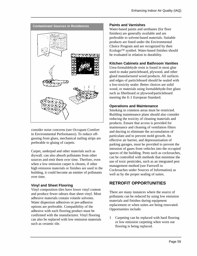
Page 59
Enhancing Indoor Air Quality (IAQ)
consider noise concerns (see Occupant Comfortin Environmental Performance). To reduce off-gassing from glues, mechanical nailing strips arepreferable to gluing of carpets.
Carpet, underpad and other materials such asdrywall. can also absorb pollutants from othersources and emit them over time. Therfore, evenwhen a low emission carpet is chosen, if otherhigh emission materials or finishes are used in thebuilding, it could become an emitter of pollutantsover time.
Vinyl and Sheet Flooring Vinyl composition tiles have lower vinyl contentand produce fewer odours than sheet vinyl. Mostadhesive materials contain volatile solvents.Water dispersion adhesives or pre-adhesiveoptions are preferable. Compatibility of theadhesive with each flooring product must beconfirmed with the manufacturer. Vinyl flooringcan also be replaced with low emission materialssuch as ceramic tile.
Paints and VarnishesWater-based paints and urethanes (for floorfinishes) are generally available and arepreferable to solvent-based materials. Suitableproducts are listed under the EnvironmentalChoice Program and are recognized by theirEcologo™ symbol. Water-based finishes shouldbe evaluated in relation to durability.
Kitchen Cabinets and Bathroom VanitiesUrea-formaldehyde resin is found in most glueused to make particleboard, plywood, and otherglued manufactured wood products. All surfacesand edges of particleboard should be sealed witha low-toxicity sealer. Better choices are solidwood, or materials using formaldehyde-free gluessuch as fiberboard or plywood/particleboardmeeting the E-1 European Standard.
Operations and MaintenanceSmoking in common areas must be restricted.Building maintenance plans should also considerreducing the toxicity of cleaning materials andproducts. Ensure that access is provided formaintenance and cleaning of ventilation filtersand ducting to eliminate the accumulation ofparticulate and to prevent mold growth. Aneffective air barrier, and depressurisation ofparking garages, must be provided to prevent theintrusion of gases from vehicles into the occupiedspaces of the building. Pests such as cockroaches,can be controlled with methods that minimise theuse of toxic pesticides, such as an integrated pestmanagement method (see Farewell toCockroaches under Sources of Information) aswell as by the proper sealing of suites.
RETROFIT OPPORTUNITIES
There are many instances where the source ofpollutants can be reduced by using low emissionmaterials and finishes during equipmentreplacement or when suites are being renovated.Opportunities include:
1 Carpeting can be replaced with hard flooringor low emission carpeting when worn outflooring is being replaced.
Contaminant Sources in Residences

Page 60
Healthy High-Rise
2 Low emission paints and finishes can be usedduring repainting and renovation.
3 Cabinets and vanities can be replaced withthose made from low emission materialsduring equipment replacement or renovation.
Sources of Information
• Exposure Guidelines for Residential IndoorAir Quality, Health Canada, 1995.
• Building Materials for the EnvironmentallyHypersensitive, CMHC, 1994.
• The Clean Air Guide, CMHC, 1993.
• Healthier Indoor Environments: CanadianSources of Residential Products and Services,CMHC, 1994.
• Farewell to Cockroaches: Getting Rid ofCockroaches the Least Toxic Way, CMHC,1998.
• Environmental Choice Program @http://www.environmentalchoice.com/
Page 61
Enhancing Indoor Air Quality (IAQ)
Related Topics
Space Heating and Air Conditioning
THE ISSUES
Occupants of high-rise residential buildings oftencomplain of inadequate, excessive, or poorly-controlled ventilation rates. Common occupantcomplaints resulting from inadequate ventilationinclude excessive humidity levels, condensationon exterior windows and walls, lingering odoursand stuffiness in suites and corridors. Commonoccupant complaints resulting from excessiveventilation include discomfort from drafts, dry air,and high heating or cooling costs.
Most high-rise residential buildings do not havemechanical ventilation systems to supply air tooccupants. Typically, corridor pressurisationsystems are installed that control the transfer ofodours between suites and provide makeup air to replace air exhausted by kitchen and bathroomexhaust fans. Ventilation air for occupants isintended to be supplied by natural ventilationthrough openable windows and infiltrationthrough the building envelope, and in some casesby makeup air provided by the corridorpressurisation system.
Recent research has shown that these corridorpressurisation systems often do not perform asintended due to two main factors: lack of envelopeairtightness and the strong stack effect in tallbuildings. Whether or not corridor pressurisationsystems are intended to provide ventilation foroccupants, suites in many high-rise residentialbuildings have been found to be over-ventilated,under-ventilated, or to receive stale ventilation airfrom other parts of the building during the heatingseason when windows are closed.
Excessive infiltration rates commonly occur dueto wind and stack induced infiltration throughleaks in the building envelope and betweenfloors. Common locations where excessive
ventilation occurs include lower suites subjectedto high stack pressures on cold winter days, andwindward facing suites on windy days.Insufficient ventilation rates commonly occur onupper floors and on leeward facing suites due toinhibited or reversed ventilation airflow.
A number of other problems are also common in high-rise residential mechanical ventilationsystems. In many instances, exhaust fans are not capable of moving a sufficient amount of air,and frequently their operation is so noisy thatoccupants do not use them. Backdrafts and noisecan also result in occupant tampering.
Ventilation air intakes located close to contaminantsources such as fireplace and boiler fumes,plumbing stacks, garbage room vents, and so oncanseriously affect indoor air quality, as can airmigration from underground parking facilities.Where corridors are not pressurised or inadequatelypressurized, odours can move from suite to suite.
A main obstacle that Healthy Highrise designersneed to overcome is the lack of regulatorydemand for apartment ventilation as well as theperception by the highrise constructionindustrythat change is both unecessary and too expensive.
Finally, the energy costs associated withinefficient fan operation and pre-heating ofventilation air are significant in many buildings.Recovery of heat from air exhausted from thebuilding is not common.
Designers of ventilation systems should considerthe following:
• Central vs. Individual Suite Systems• Compartmentalization• Filtering of Supply Air• Reducing Heating Costs• Ensuring Adequate AirFlow• System Control• Commissioning• Operating and Maintenance
MECHANICAL VENTILATION
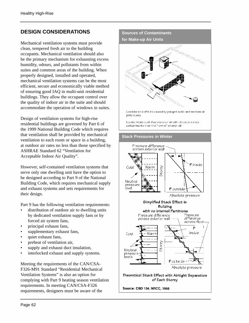
Page 62
Healthy High-Rise
DESIGN CONSIDERATIONS
Mechanical ventilation systems must provideclean, tempered fresh air to the buildingoccupants. Mechanical ventilation should also be the primary mechanism for exhausting excesshumidity, odours, and pollutants from withinsuites and common areas of the building. Whenproperly designed, installed and operated,mechanical ventilation systems can be the mostefficient, secure and economically viable methodof ensuring good IAQ in multi-unit residentialbuildings. They allow the occupant control overthe quality of indoor air in the suite and shouldaccommodate the operation of windows in suites.
Design of ventilation systems for high-riseresidential buildings are governed by Part 6 ofthe 1999 National Building Code which requiresthat ventilation shall be provided by mechanicalventilation to each room or space in a building, at outdoor air rates no less than those specified byASHRAE Standard 62 “Ventilation forAcceptable Indoor Air Quality”.
However, self-contained ventilation systems thatserve only one dwelling unit have the option to be designed according to Part 9 of the NationalBuilding Code, which requires mechanical supplyand exhaust systems and sets requirements fortheir design.
Part 9 has the following ventilation requirements:• distribution of outdoor air to dwelling units
by dedicated ventilation supply fans or byforced air system fans,
• principal exhaust fans,• supplementary exhaust fans,• quiet exhaust fans,• preheat of ventilation air,• supply and exhaust duct insulation,• interlocked exhaust and supply systems.
Meeting the requirements of the CAN/CSA-F326-M91 Standard “Residential MechanicalVentilation Systems” is also an option forcomplying with Part 9 heating season ventilationrequirements. In meeting CAN/CSA-F326requirements, designers must be aware of the
Sources of Contaminants
for Make-up Air Units
Stack Pressures in Winter
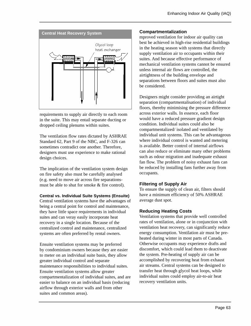
Page 63
Enhancing Indoor Air Quality (IAQ)
requirements to supply air directly to each roomin the suite. This may entail separate ducting ordropped ceiling plenums within suites.
The ventilation flow rates dictated by ASHRAEStandard 62, Part 9 of the NBC, and F-326 cansometimes contradict one another. Therefore,designers must use experience to make rationaldesign choices.
The implication of the ventilation system designon fire safety also must be carefully analysed(e.g. need to move air across fire separations-must be able to shut for smoke & fire control).
Central vs. Individual Suite Systems (Ensuite) Central ventilation systems have the advantages ofbeing a central point for control and maintenance,they have little space requirements in individualsuites and can veray easily incorporate heatrecovery in a single location. Because of thecentralized control and maintenance, centralizedsystems are often preferred by rental owners.
Ensuite ventilation systems may be preferred by condominium owners because they are easierto meter on an individual suite basis, they allowgreater individual control and separatemaintenance responsibilities to individual suites.Ensuite ventilation systems allow greatercompartmentalization of individual suites, and areeasier to balance on an individual basis (reducingairflow through exterior walls and from othersuites and common areas).
Compartmentalizationmproved ventilation for indoor air quality canbest be achieved in high-rise residential buildingsin the heating season with systems that directlysupply ventilation air to occupants within theirsuites. And because effective performance ofmechanical ventilation systems cannot be ensuredunless internal air flows are controlled, theairtightness of the building envelope andseparations between floors and suites must alsobe considered.
Designers might consider providing an airtightseparation (compartmentalisation) of individualfloors, thereby minimising the pressure differenceacross exterior walls. In essence, each floorwould have a reduced pressure gradient designcondition. Individual suites could also becompartmentalized/ isolated and ventilated byindividual unit systems. This can be advantageouswhere individual control is wanted and meteringis available. Better control of internal airflowscan also reduce or eliminate many other problemssuch as odour migration and inadequate exhaustfan flow. The problem of noisy exhaust fans canbe reduced by installing fans further away fromoccupants.
Filtering of Supply AirTo ensure the supply of clean air, filters shouldhave a minimum efficiency of 50% ASHRAEaverage dust spot.
Reducing Heating CostsVentilation systems that provide well controlledrates of ventilation, alone or in conjunction withventilation heat recovery, can significantly reduceenergy consumption. Ventilation air must be pre-heated during winter in most parts of Canada.Otherwise occupants may experience drafts anddiscomfort, which could lead them to deactivatethe system. Pre-heating of supply air can beaccomplished by recovering heat from exhaust air streams. Central systems can be designed totransfer heat through glycol heat loops, whileindividual suites could employ air-to-air heatrecovery ventilation units.
Central Heat Recovery System
Glycol loopheat exchanger
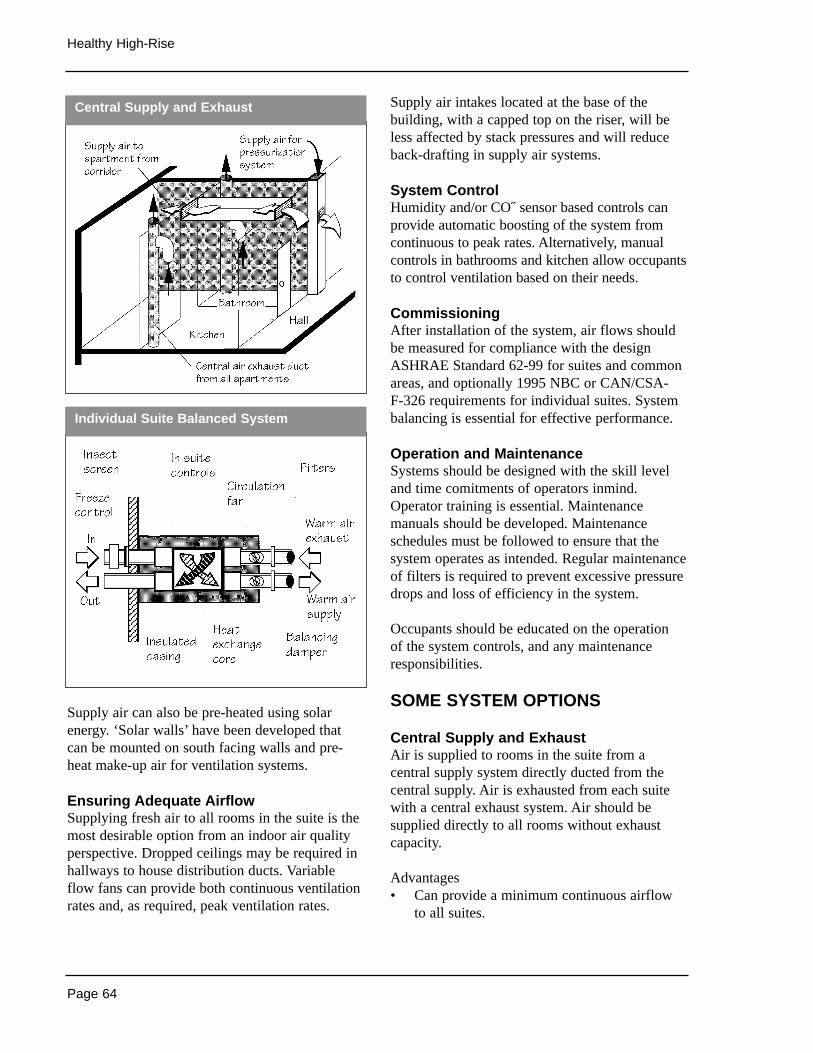
Page 64
Healthy High-Rise
Supply air can also be pre-heated using solarenergy. ‘Solar walls’ have been developed thatcan be mounted on south facing walls and pre-heat make-up air for ventilation systems.
Ensuring Adequate AirflowSupplying fresh air to all rooms in the suite is themost desirable option from an indoor air qualityperspective. Dropped ceilings may be required inhallways to house distribution ducts. Variableflow fans can provide both continuous ventilationrates and, as required, peak ventilation rates.
Supply air intakes located at the base of thebuilding, with a capped top on the riser, will beless affected by stack pressures and will reduceback-drafting in supply air systems.
System ControlHumidity and/or CO˝ sensor based controls canprovide automatic boosting of the system fromcontinuous to peak rates. Alternatively, manualcontrols in bathrooms and kitchen allow occupantsto control ventilation based on their needs.
CommissioningAfter installation of the system, air flows shouldbe measured for compliance with the designASHRAE Standard 62-99 for suites and commonareas, and optionally 1995 NBC or CAN/CSA-F-326 requirements for individual suites. Systembalancing is essential for effective performance.
Operation and MaintenanceSystems should be designed with the skill leveland time comitments of operators inmind.Operator training is essential. Maintenancemanuals should be developed. Maintenanceschedules must be followed to ensure that thesystem operates as intended. Regular maintenanceof filters is required to prevent excessive pressuredrops and loss of efficiency in the system.
Occupants should be educated on the operation of the system controls, and any maintenanceresponsibilities.
SOME SYSTEM OPTIONS
Central Supply and ExhaustAir is supplied to rooms in the suite from acentral supply system directly ducted from thecentral supply. Air is exhausted from each suitewith a central exhaust system. Air should besupplied directly to all rooms without exhaustcapacity.
Advantages• Can provide a minimum continuous airflow
to all suites.
Central Supply and Exhaust
Individual Suite Balanced System
Page 65
Enhancing Indoor Air Quality (IAQ)
• Reduces suite depressurisation and minimises envelope air leakage.
• Heat recovery to pre-heat supply air can beprovided from a central location.
• Can be supplemented with individual suiteexhaust or a booster fan in a central shaft.
• Single point of maintenance.• No supply air intake required for each
apartment.• Building operators can control ventilation
rates and ensure that the building is properlyventilated.
• Less space required in apartments than forensuite systems.
Disadvantages• Supply air transferred from corridors (if not
directly ducted) may not meet fire safetyrequirements.
• Supply air inlets may be sealed by occupantsto reduce noise and drafts (if not directlyducted).
• Increased building stack effect due toincreased coupling of floors.
• Loss of occupant control.• Larger common space committment(ie.
mechanical rooms).• Greater smoke, odour, noise and pest transfer
is possible.
Individual Unit Exhaust - Central Supply AirDwelling units operate under continuous exhaustfrom individual dwelling unit systems. Fresh airis supplied through a central supply system -directly ducted from the central supply.
Advantages• Can provide a minimum continuous airflow
to all suites.• Greater compartmentalisation of dwelling
units.• Exhaust rate controllable by occupants.• No supply air intake required for each
apartment.
Disadvantages• No heat recovery of exhaust air possible.• Difficult to balance.• Loss of control by building owner• Could pressurize the building and cause
envelope problems.• Supply air transferred from corridors (if not
directly ducted) may not meet fire safetyrequirements.
• Supply air inlets may be sealed by occupantsto reduce noise and drafts (if not directlyducted).
Individual Suite Balanced SystemAir is supplied and exhausted from each dwellingunit with an individual unit heat recoveryventilation system (HRV), which recovers heat(or cold) from exhaust air flow to temper theincoming airflow.
Advantages• Can provide a minimum continuous airflow
to all suites.• Heat recovery of exhaust air reduces energy
consumption.• Allows compartmentalisation of individual
suite.• Balanced air pressure in suites reduces
airflow though exterior walls, vertical walls,vertical shafts, and from other suites andcommon areas.
• Easy to balance.• Increased occupant control.• Usage is billable to occupants.
Disadvantages• Capital cost of HRV unit.• Requires balancing.• Requires separate system for
corridors.• Many points of maintenance.• Large number of motors consuming energy.
Page 66
Healthy High-Rise
RETROFIT OPPORTUNITIES
Ventilation systems in existing buildings oftenperform poorly compared to their originalspecifications. Retrofit opportunities to improveperformance include:
1 Balancing airflows – Corridor pressurisationand central exhaust systems should berebalanced to ensure that air supplies andexhaust rates are meeting their originalspecifications and are properly distributedthroughout the building.
2 Installing ventilation supply to individualrooms –Central corridor pressurisationsystems can be modified to supply ventilationair directly to individual suites. The only timethat such a retrofit is possible is during majorrenovation.
3 HRV units can be installed in exterior wallsof individual suites during renovation of eachsuite.
Sources of Information
• Mechanical and Electrical Systems inApartments and Multi-Suite Buildings,A Practitioners Guide, CMHC, 1999.
• The High-Rise Residential ConstructionGuide 1995, Ontario New Home WarrantyProgram.
• Energy And Water Efficiency in Multi UnitResidential Buildings, Technical Manual,CMHC.
• Fundamentals, American Society of HeatingRefigerating and Air Conditioning EngineersInc. (ASHRAE).
• ASHRAE Standard 90.1-1999, EnergyStandard for Buildings Except Low-RiseResidential Buildings, American Society ofHeating Refigerating and Air ConditioningEngineers Inc. (ASHRAE)
• ASHRAE Standard 62, American Society ofHeating Refigerating and Air ConditioningEngineers Inc. (ASHRAE)
• Model National Energy Code for Buildings,National Research Council of Canada.
• CAN/CSA –F326-M91 ResidentialMechanical Systems, Canadian StandardsAssociation.
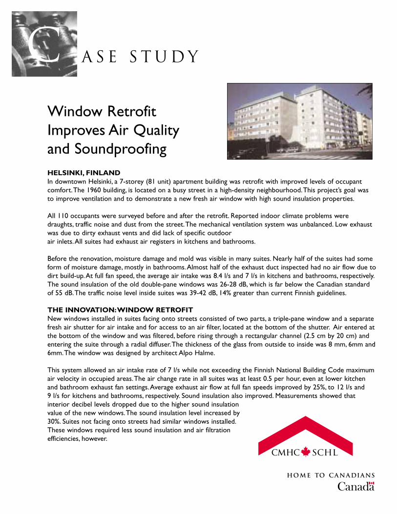
A S E S T U D YCWindow Retrofit Improves Air Quality and SoundproofingHELSINKI, FINLANDIn downtown Helsinki, a 7-storey (81 unit) apartment building was retrofit with improved levels of occupantcomfort.The 1960 building, is located on a busy street in a high-density neighbourhood.This project’s goal wasto improve ventilation and to demonstrate a new fresh air window with high sound insulation properties.
All 110 occupants were surveyed before and after the retrofit. Reported indoor climate problems weredraughts, traffic noise and dust from the street.The mechanical ventilation system was unbalanced. Low exhaustwas due to dirty exhaust vents and did lack of specific outdoor air inlets.All suites had exhaust air registers in kitchens and bathrooms.
Before the renovation, moisture damage and mold was visible in many suites. Nearly half of the suites had someform of moisture damage, mostly in bathrooms.Almost half of the exhaust duct inspected had no air flow due todirt build-up.At full fan speed, the average air intake was 8.4 l/s and 7 l/s in kitchens and bathrooms, respectively.The sound insulation of the old double-pane windows was 26-28 dB, which is far below the Canadian standardof 55 dB.The traffic noise level inside suites was 39-42 dB, 14% greater than current Finnish guidelines.
THE INNOVATION:WINDOW RETROFITNew windows installed in suites facing onto streets consisted of two parts, a triple-pane window and a separatefresh air shutter for air intake and for access to an air filter, located at the bottom of the shutter. Air entered atthe bottom of the window and was filtered, before rising through a rectangular channel (2.5 cm by 20 cm) andentering the suite through a radial diffuser.The thickness of the glass from outside to inside was 8 mm, 6mm and6mm.The window was designed by architect Alpo Halme.
This system allowed an air intake rate of 7 l/s while not exceeding the Finnish National Building Code maximumair velocity in occupied areas.The air change rate in all suites was at least 0.5 per hour, even at lower kitchenand bathroom exhaust fan settings.Average exhaust air flow at full fan speeds improved by 25%, to 12 l/s and 9 l/s for kitchens and bathrooms, respectively. Sound insulation also improved. Measurements showed thatinterior decibel levels dropped due to the higher sound insulationvalue of the new windows.The sound insulation level increased by30%. Suites not facing onto streets had similar windows installed.These windows required less sound insulation and air filtrationefficiencies, however.
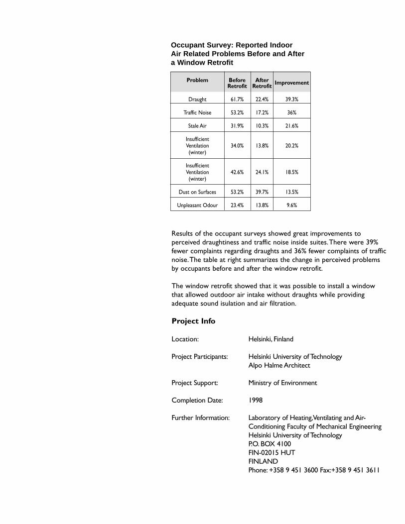
Occupant Survey: Reported Indoor Air Related Problems Before and After a Window Retrofit
Results of the occupant surveys showed great improvements toperceived draughtiness and traffic noise inside suites.There were 39%fewer complaints regarding draughts and 36% fewer complaints of trafficnoise.The table at right summarizes the change in perceived problemsby occupants before and after the window retrofit.
The window retrofit showed that it was possible to install a windowthat allowed outdoor air intake without draughts while providingadequate sound isulation and air filtration.
Project Info
Location: Helsinki, Finland
Project Participants: Helsinki University of TechnologyAlpo Halme Architect
Project Support: Ministry of Environment
Completion Date: 1998
Further Information: Laboratory of Heating,Ventilating and Air-Conditioning Faculty of Mechanical EngineeringHelsinki University of Technology P.O. BOX 4100 FIN-02015 HUT FINLANDPhone: +358 9 451 3600 Fax:+358 9 451 3611
Problem Before After ImprovementRetrofit Retrofit
Draught 61.7% 22.4% 39.3%
Traffic Noise 53.2% 17.2% 36%
Stale Air 31.9% 10.3% 21.6%
InsufficientVentilation 34.0% 13.8% 20.2%(winter)
InsufficientVentilation 42.6% 24.1% 18.5%(winter)
Dust on Surfaces 53.2% 39.7% 13.5%
Unpleasant Odour 23.4% 13.8% 9.6%
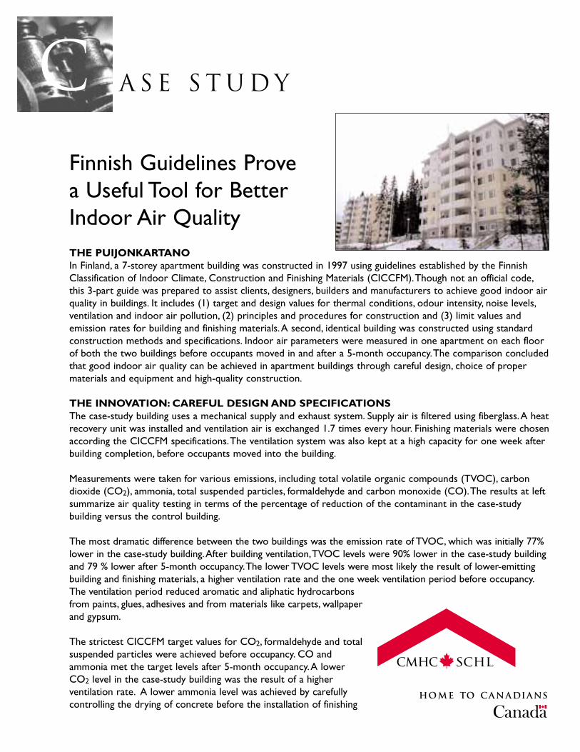
C A S E S T U D Y
Finnish Guidelines Prove a Useful Tool for BetterIndoor Air QualityTHE PUIJONKARTANOIn Finland, a 7-storey apartment building was constructed in 1997 using guidelines established by the FinnishClassification of Indoor Climate, Construction and Finishing Materials (CICCFM).Though not an official code,this 3-part guide was prepared to assist clients, designers, builders and manufacturers to achieve good indoor airquality in buildings. It includes (1) target and design values for thermal conditions, odour intensity, noise levels,ventilation and indoor air pollution, (2) principles and procedures for construction and (3) limit values andemission rates for building and finishing materials.A second, identical building was constructed using standardconstruction methods and specifications. Indoor air parameters were measured in one apartment on each floorof both the two buildings before occupants moved in and after a 5-month occupancy.The comparison concludedthat good indoor air quality can be achieved in apartment buildings through careful design, choice of propermaterials and equipment and high-quality construction.
THE INNOVATION: CAREFUL DESIGN AND SPECIFICATIONSThe case-study building uses a mechanical supply and exhaust system. Supply air is filtered using fiberglass.A heatrecovery unit was installed and ventilation air is exchanged 1.7 times every hour. Finishing materials were chosenaccording the CICCFM specifications.The ventilation system was also kept at a high capacity for one week afterbuilding completion, before occupants moved into the building.
Measurements were taken for various emissions, including total volatile organic compounds (TVOC), carbondioxide (CO2), ammonia, total suspended particles, formaldehyde and carbon monoxide (CO).The results at leftsummarize air quality testing in terms of the percentage of reduction of the contaminant in the case-studybuilding versus the control building.
The most dramatic difference between the two buildings was the emission rate of TVOC, which was initially 77%lower in the case-study building.After building ventilation,TVOC levels were 90% lower in the case-study buildingand 79 % lower after 5-month occupancy.The lower TVOC levels were most likely the result of lower-emittingbuilding and finishing materials, a higher ventilation rate and the one week ventilation period before occupancy.The ventilation period reduced aromatic and aliphatic hydrocarbonsfrom paints, glues, adhesives and from materials like carpets, wallpaperand gypsum.
The strictest CICCFM target values for CO2, formaldehyde and totalsuspended particles were achieved before occupancy. CO andammonia met the target levels after 5-month occupancy.A lowerCO2 level in the case-study building was the result of a higherventilation rate. A lower ammonia level was achieved by carefullycontrolling the drying of concrete before the installation of finishing
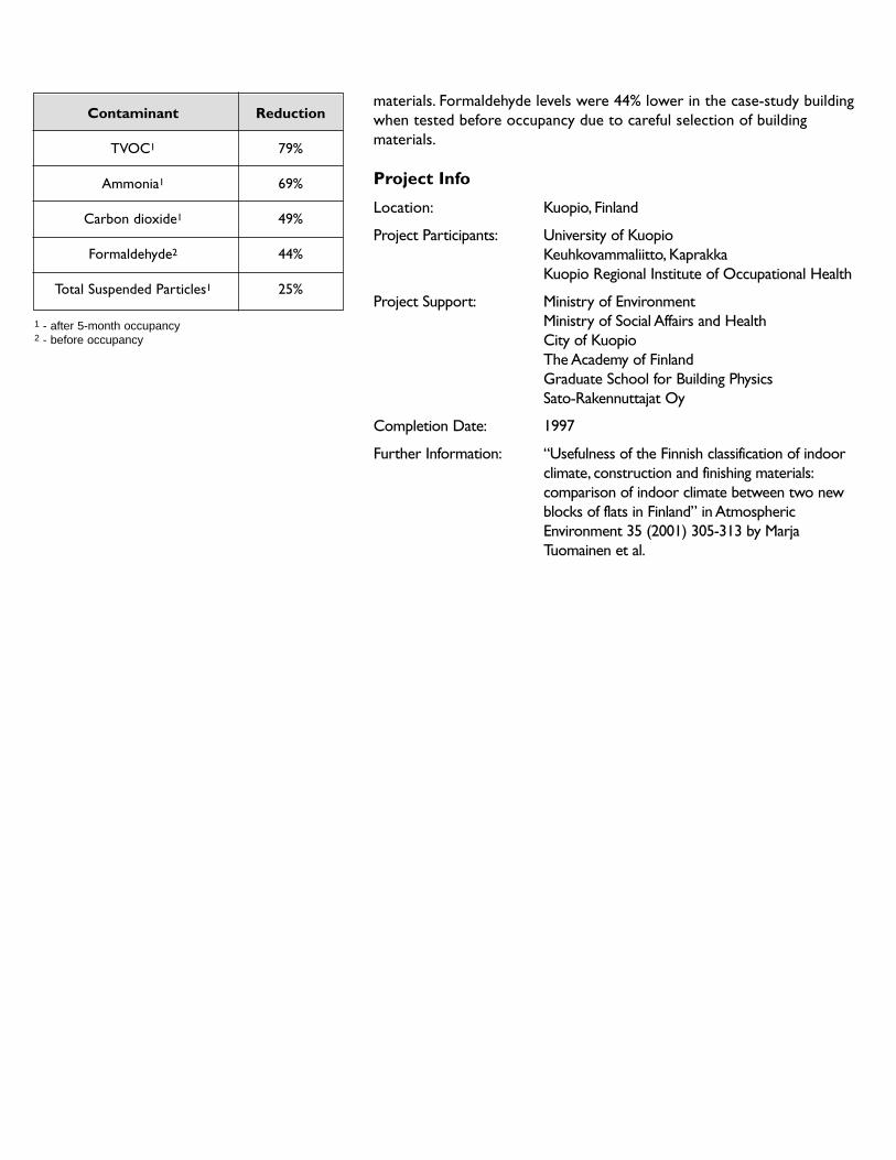
1 - after 5-month occupancy2 - before occupancy
Contaminant Reduction
TVOC1 79%
Ammonia1 69%
Carbon dioxide1 49%
Formaldehyde2 44%
Total Suspended Particles1 25%
materials. Formaldehyde levels were 44% lower in the case-study buildingwhen tested before occupancy due to careful selection of buildingmaterials.
Project Info
Location: Kuopio, Finland
Project Participants: University of KuopioKeuhkovammaliitto, Kaprakka Kuopio Regional Institute of Occupational Health
Project Support: Ministry of EnvironmentMinistry of Social Affairs and HealthCity of KuopioThe Academy of FinlandGraduate School for Building PhysicsSato-Rakennuttajat Oy
Completion Date: 1997
Further Information: “Usefulness of the Finnish classification of indoorclimate, construction and finishing materials:comparison of indoor climate between two newblocks of flats in Finland” in AtmosphericEnvironment 35 (2001) 305-313 by MarjaTuomainen et al.
Page 71
ENHANCING ENVIRONMENTAL PERFORMANCE
In This Section
Site Planning• preservation and protection of natural features• building location and footprint• building orientation
Materials Selection• source / quality of materials• embodied energy• quantities of materials• impact on occupant health• impact on natural ecosystems• materials selection guidelines
Solid Waste• building construction• building operation• building demolition• waste management plans
Water• domestic indoor water uses • HVAC systems• exterior water use• on-site water treatment
Landscape Practices• water-efficient• energy-efficient • stormwater management
Occupant Comfort - Noise• verification• doors• windows• air borne noise• impact noise• mechanical equipment rooms• plumbing system• installation
Regional Differences
Case Studies
Concerns for the susceptibility of ourenvironment are increasing. The deterioration of the ozone layer and air quality in urban areas,the depletion of fresh water supplies and thedegradation of water courses, and the loss ofnatural habitats all represent societal problemsthat need to be addressed.
Residential development has a major impact onthe environment at both local and global scales. A new building can destroy local naturalecosystems, and can impact negatively on adjacentdevelopment. Both the construction and operationof residential buildings consume vast quantities ofenergy, materials, water, and land. The wasteemissions and pollution associated with buildingsare also significant. In order to sustain the qualityof the environment and healthy lifestyles, it iscrucial that residential development use resourcesmore effectively and more efficiently, whilepreserving the integrity of the local ecosystem. In response to these needs, the design andconstruction industry has begun to make advances.
In most cases, environmentally responsive design will not significantly increase design orconstruction costs. For example, orienting abuilding to optimise solar gains, or specifyinglow flow water fixtures, can result in operatingcost savings. At the same time, there are manyprecedents of residential developments where an environmentally responsive design approachresulted in greatly reduced infrastructure costs.Indeed, when a lifecycle assessment approach isused, the benefits of ‘green’ design far outweighthe costs.
The following section provides an overview of possible approaches for enhancing theenvironmental performance of high-riseresidential buildings. It discusses this issue fromthe point of view of local ecological impacts,resource use and attendant waste emissions, and indoor occupant health.
Page 72
Healthy High-Rise
Related Topics
Wetting of Building EnvelopesSpace Heating and Air ConditioningMechanical VentilationSolid WasteLandscape PracticesFlexibility
THE ISSUES
A building has a permanent environmental impacton its site, both in terms of changes to thesurrounding ecosystem, and its relationship to the local community. Initial site planning is key to the overall environmental performance of thebuilding. It has ramifications on all other aspectsof design. Through careful attention during earlystages of design, the building designer cananticipate negative ecological impacts, improvethe quality of the development, and enhance thesustainability of the neighbourhood. The basicconsiderations include:
• Preservation and Protection of NaturalFeatures
• Building Location and Footprint• Building Orientation
DESIGN CONSIDERATIONS
Preservation and Protection of NaturalFeaturesThe site plan should be premised uponpreserving, protecting, and enhancing suchnatural features as site contours, stream channels,hydrological flows, existing vegetation, scenicviews, and wildlife habitats. These features allplay integral roles in the proper functioning of the ecosystem as a whole, and can contributesignificantly to proper building functioning.
Restrictions on development of environmentally-sensitive or important productive lands arecrucial. Agricultural, forest renewal andhazardous lands, or lands that might result in
extensive environmental damage, should havelimited development. For example, steep slopesand hillsides, flood plains, and wetlands are allexamples of areas where development should be restricted and / or regulated.
Building Location and FootprintThe construction of high-rise buildings can affectthe local microclimate, modifying wind and sunpatterns in the area, and shading other buildingsand ecosystems. The building should be sited tocreate desirable summer and winter microclimatesat the pedestrian level.
The location of a building on a site can result in positive or negative environmental impacts.Consideration should be given to the impact ofthe building on views, how much of the site willbe disturbed both during construction andoperation, soil capabilities, linkages totransportation networks, existing buildings onsite, changes to the microclimate caused byaltering the contours of the land, and so on.
In order to minimise site disturbance forconstruction, buildings and access roads can bealigned to follow the length of existing contours.
The building’s impact upon local solar access isan important consideration. Buildings should belocated to minimise the loss of solar access tosurrounding buildings and publicly accessible,open space areas. This is an importantconsideration for colder climates in particular.
Ideally, high-density development should havegood access to services and amenities,maximising the potential for pedestrian travel andminimising the need for the automobile. Easyaccess to public transit, stores, health services,schools, and recreational facilities all provide fora more sustainable approach to development.
Opportunities for mixed uses at the lower levelsof the building can reduce infrastructure costs andprovide for a livelier community aspect in the
SITE PLANNING
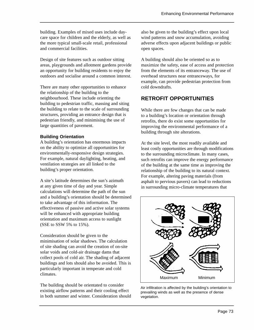
Page 73
Enhancing Environmental Performance
building. Examples of mixed uses include day-care space for children and the elderly, as well asthe more typical small-scale retail, professionaland commercial facilities.
Design of site features such as outdoor sittingareas, playgrounds and allotment gardens providean opportunity for building residents to enjoy theoutdoors and socialise around a common interest.
There are many other opportunities to enhancethe relationship of the building to theneighbourhood. These include orienting thebuilding to pedestrian traffic, massing and sitingthe building to relate to the scale of surroundingstructures, providing an entrance design that ispedestrian friendly, and minimising the use oflarge quantities of pavement.
Building OrientationA building’s orientation has enormous impacts on the ability to optimize all opportunities forenvironmentally-responsive design strategies. For example, natural daylighting, heating, andventilation strategies are all linked to thebuilding’s proper orientation.
A site’s latitude determines the sun’s azimuth at any given time of day and year. Simplecalculations will determine the path of the sunand a building’s orientation should be determinedto take advantage of this information. Theeffectiveness of passive and active solar systemswill be enhanced with appropriate buildingorientation and maximum access to sunlight (SSE to SSW 5% to 15%).
Consideration should be given to theminimisation of solar shadows. The calculation of site shading can avoid the creation of on-sitesolar voids and cold-air drainage dams thatcollect pools of cold air. The shading of adjacentbuildings and lots should also be avoided. This isparticularly important in temperate and coldclimates.
The building should be orientated to considerexisting airflow patterns and their cooling effectin both summer and winter. Consideration should
also be given to the building’s effect upon localwind patterns and snow accumulation, avoidingadverse effects upon adjacent buildings or publicopen spaces.
A building should also be oriented so as tomaximize the safety, ease of access and protectionfrom the elements of its entranceway. The use ofoverhead structures near entranceways, forexample, can provide pedestrian protection fromcold downdrafts.
RETROFIT OPPORTUNITIES
While there are few changes that can be made to a building’s location or orientation throughretrofits, there do exist some opportunities forimproving the environmental performance of abuilding through site alterations.
At the site level, the most readily available andleast costly opportunities are through modificationsto the surrounding microclimate. In many cases,such retrofits can improve the energy performanceof the building at the same time as improving therelationship of the building to its natural context.For example, altering paving materials (fromasphalt to pervious pavers) can lead to reductionsin surrounding micro-climate temperatures that
Air infiltration is affected by the building’s orientation toprevailing winds as well as the presence of densevegetation.
Maximum Minimum
Page 74
Healthy High-Rise
in turn reduce the cooling loads on the buildingwhile also addressing stormwater run-off issues.Another example is to add landscapinginterventions that enhance the natural features of the site while also improving the building’senergy performance. These can include suchthings as adding deciduous plants on the south and west sides of a building to allow for summercooling and winter solar access.
Sources of Information
• Sun, Wind, and Light: Architectural DesignStrategies, Brown, G.Z., John Wiley & Sons,U.S.A., 1985.
• Sunlighting as Formgiver for Architecture,Lam, William M.C., Van Nostrand ReinholdCompany, U.S.A., 1986.
• Santa Monica Green Building Design &Construction Guidelines, The Sheltair Groupet. al, 1999.
• Time-Saver Standards for LandscapeArchitecture, Harris C. & N. Dines, McGraw-Hill, U.S.A., 1998.
• Energy and Water Efficiency in Multi- UnitResidential Buildings, Technical Manual,CMHC, 2000.
• Tap The Sun: Passive Solar Techniques andHome Designs, CMHC, 1998.
• The Climatic Dwelling, E. O’Cofaigh, J.A. Olley, and J.O. Lewis. Energy ResearchGroup, School of Architecture, UniversityCollege of Dublin, Republic of Ireland, James & James, 1996.
Page 75
Enhancing Environmental Performance
Related Topics
Parking GaragesSource ReductionSolid WasteLandscape PracticesFlexibility
THE ISSUES
The materials used for the construction, operation,maintenance and renovation of buildings representenormous quantities of resources. As well, theextraction, transformation, use and disposal of rawmaterials cause equally significant impacts on theenvironment. Habitat destruction, resourcedepletion, air pollution, and solid waste representsome of the environmental costs associated withthe flow of construction materials. For this reason,design professionals now often includeenvironmental considerations into the materialsselection process. In particular, life-cycleassessment / analysis of construction materials anddesign guidelines that specify the use of ‘green’materials are available. The key considerationsinvolved in the selection of materials include:
• Source / quality of materials• Embodied energy• Quantities of materials• Impact on occupant health• Impact on natural ecosystems• Materials selection guidelines
DESIGN CONSIDERATIONS
Source / Quality of MaterialsMany materials come from sources which areconsidered non-renewable or which involve moresevere negative environmental impacts thanothers. Tropical hardwoods are considered ascarce resource, not just because they representan endangered species, but also because theacquisition process causes dire ramifications onbiodiversity. The selection of materials shouldinvolve consideration of the source in order to
ensure that a non-renewable material is not beingused. For wood products, third-party forestcertification is the best way to guarantee thesuitability of the source.
The source of materials also refers to whethermaterials are virgin or whether they are salvaged.Using salvaged materials and materials withrecycled content reduces the extraction of rawresources. Assemblies that allow easy extractionof the material for recycling when the building is eventually replaced also result in reducedenvironmental impact.
It is also necessary to consider the quality of thematerials. Lower quality, less durable materialswill require frequent replacement—meaning thatmore resources will be used without adding anyvalue to the building. While lower qualitymaterials may cost less at the building’sinception, both the economic and environmentalcost will be much higher over the lifetime of thebuilding. Durable materials with a long servicelife typically are those that are low-maintenanceand that result in lower operation costs. Hardflooring, for example, has several times theservice life of vinyl flooring or carpets, andreduces both waste and cleaning requirements.
Embodied EnergyEmbodied energy is the term used to describe the energy input invested in a material duringextraction, manufacturing, transportation, andinstallation. Through choice of materials, thedesigner can greatly influence the embodiedenergy invested in the building as well as theenergy required to operate the facility. The goal is not to minimize embodied energy per se, but to consider its significant contribution to totallife-cycle energy associated with the building. Asa case in point, processing of recycled aluminumrequires only 5% of the energy necessary toproduce aluminum from bauxite.
Because only 7% to 10% of the embodied energyin buildings is the result of the on-site
MATERIALS SELECTION
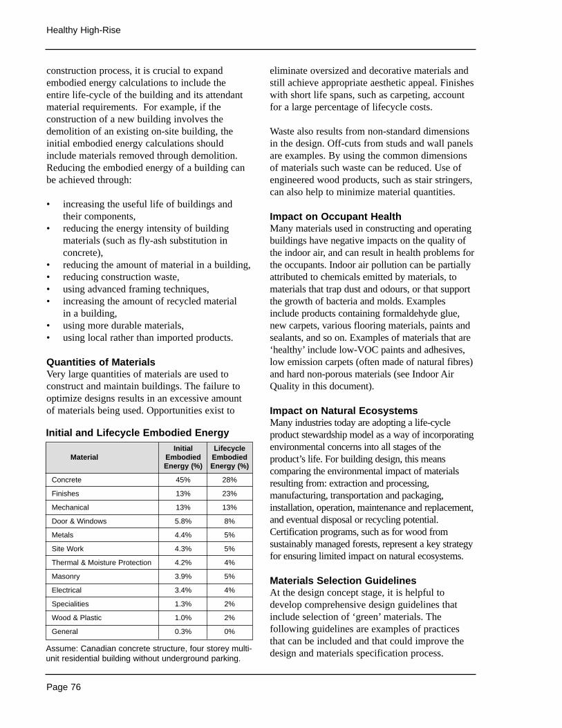
Page 76
Healthy High-Rise
construction process, it is crucial to expandembodied energy calculations to include theentire life-cycle of the building and its attendantmaterial requirements. For example, if theconstruction of a new building involves thedemolition of an existing on-site building, theinitial embodied energy calculations shouldinclude materials removed through demolition.Reducing the embodied energy of a building canbe achieved through:
• increasing the useful life of buildings andtheir components,
• reducing the energy intensity of buildingmaterials (such as fly-ash substitution inconcrete),
• reducing the amount of material in a building,• reducing construction waste,• using advanced framing techniques,• increasing the amount of recycled material
in a building,• using more durable materials,• using local rather than imported products.
Quantities of MaterialsVery large quantities of materials are used toconstruct and maintain buildings. The failure tooptimize designs results in an excessive amountof materials being used. Opportunities exist to
eliminate oversized and decorative materials andstill achieve appropriate aesthetic appeal. Finisheswith short life spans, such as carpeting, accountfor a large percentage of lifecycle costs.
Waste also results from non-standard dimensionsin the design. Off-cuts from studs and wall panelsare examples. By using the common dimensionsof materials such waste can be reduced. Use ofengineered wood products, such as stair stringers,can also help to minimize material quantities.
Impact on Occupant HealthMany materials used in constructing and operatingbuildings have negative impacts on the quality ofthe indoor air, and can result in health problems forthe occupants. Indoor air pollution can be partiallyattributed to chemicals emitted by materials, tomaterials that trap dust and odours, or that supportthe growth of bacteria and molds. Examplesinclude products containing formaldehyde glue,new carpets, various flooring materials, paints andsealants, and so on. Examples of materials that are‘healthy’ include low-VOC paints and adhesives,low emission carpets (often made of natural fibres)and hard non-porous materials (see Indoor AirQuality in this document).
Impact on Natural EcosystemsMany industries today are adopting a life-cycleproduct stewardship model as a way of incorporatingenvironmental concerns into all stages of theproduct’s life. For building design, this meanscomparing the environmental impact of materialsresulting from: extraction and processing,manufacturing, transportation and packaging,installation, operation, maintenance and replacement,and eventual disposal or recycling potential.Certification programs, such as for wood fromsustainably managed forests, represent a key strategyfor ensuring limited impact on natural ecosystems.
Materials Selection GuidelinesAt the design concept stage, it is helpful todevelop comprehensive design guidelines thatinclude selection of ‘green’ materials. Thefollowing guidelines are examples of practicesthat can be included and that could improve thedesign and materials specification process.
Initial and Lifecycle Embodied Energy
Assume: Canadian concrete structure, four storey multi-unit residential building without underground parking.
Initial LifecycleMaterial Embodied Embodied
Energy (%) Energy (%)
Concrete 45% 28%
Finishes 13% 23%
Mechanical 13% 13%
Door & Windows 5.8% 8%
Metals 4.4% 5%
Site Work 4.3% 5%
Thermal & Moisture Protection 4.2% 4%
Masonry 3.9% 5%
Electrical 3.4% 4%
Specialities 1.3% 2%
Wood & Plastic 1.0% 2%
General 0.3% 0%
Page 77
Enhancing Environmental Performance
RETROFIT OPPORTUNITIES
While there are few changes that can be made to a building’s location or orientation throughretrofits, there do exist some opportunities forimproving the environmental performance of a building through site alterations.
At the site level, the most readily available andleast costly opportunities are throughmodifications to the surrounding microclimate. Inmany cases, such retrofits can improve the energyperformance of the building at the same time asimproving the relationship of the building to itsnatural context. For example, altering pavingmaterials (from asphalt to pervious pavers) canlead to reductions in surrounding micro-climatetemperatures that in turn reduce the cooling loadson the building while also addressing stormwaterrun-off issues. Another example is to addlandscaping interventions that enhance the naturalfeatures of the site while also improving thebuilding’s energy performance. These can includesuch things as adding deciduous plants on thesouth and west sides of a building to allow forsummer cooling and winter solar access.
Examples of Green BuildingMaterials
Foundations• ABS drain tile with recycled content• Pier foundation systems• Concrete with fly-ash content
Walls• Insulation with high recycled content• CFC and HCFC-free insulations• Cellulose insulation• Drywall with high recycled content • Steel / aluminium/ vinyl with recycled
content
Roofing• Recycled rubber roof deck• CFC and HCFC-free rigid insulations• ‘Green’ Roofs
Interior Finishes• Zero- and Low-VOC paints• Zero- and Low-VOC caulks and adhesives• Bio-based natural materials (cork, linoleum,
wool, sisal, etc.)
Landscaping• Rubber flooring from recycled tires• Chipped wood waste for flower beds• Crushed concrete as aggregate for road
sub-base
Sources of Information
• Environmental Building News: @http://www.buildinggreen.com(especially “Building Materials: What MakesA Product Green?” from EBN Volume 9,No.1, January 2000)
• Environmental Resource Guide, TheAmerican Institute of Architects, John Wiley& Sons, 1996.
• Santa Monica Green Building Design &Construction Guidelines, The Sheltair Groupet.al, 1999.
• Building Materials for the EnvironmentallyHypersensitive, CMHC, 1995.
Materials Selection
1 Specify recycled products and attendantstrategies.
2 Specify reuse of salvaged buildingmaterials.
3 Design with panel, pre-cut andengineered constructio products.
4 Specify durable exterior and interiorfinishes.
5 Specify wood from sustainably-managedsources.
6 Use low-emissions finishes and interiormaterials.
source: Santa Monica Green Building Design& Construction Guidelines, 1999
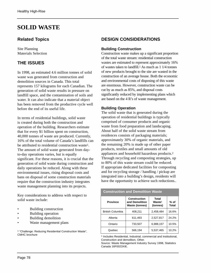
DESIGN CONSIDERATIONS
Building ConstructionConstruction waste makes up a significant proportionof the total waste stream: residential constructionwastes are estimated to represent approximately 16%of wastes taken to landfill.1 As much as 1 1/4 tonnesof new products brought to the site are wasted in theconstruction of an average house. Both the economicand environmental costs of disposing of this wasteare enormous. However, construction waste can becut by as much as 85%, and disposal costssignificantly reduced by implementing plans whichare based on the 4 R’s of waste management.
Building OperationThe solid waste that is generated during theoperation of residential buildings is typicallycomprised of consumer products and organicwaste from food preparation and landscaping.About half of the solid waste stream fromresidences consists of packaging materials;approximately 30% of organic materials, and the remaining 20% is made up of other paperproducts, textiles and small amounts of oldappliances and household hazardous products.2Through recycling and composting strategies, upto 80% of this waste stream could be reduced. If appropriate dedicated facilities for compostingand for recycling storage / handling / pickup areintegrated into a building’s design, residents willhave the opportunity to achieve such reductions..
Page 78
Healthy High-Rise
Related Topics
Site PlanningMaterials Selection
THE ISSUES
In 1998, an estimated 4.6 million tonnes of solidwaste was generated from construction anddemolition sources in Canada. This totalrepresents 157 kilograms for each Canadian. Thegeneration of solid waste results in pressure onlandfill space, and the contamination of soils andwater. It can also indicate that a material objecthas been removed from the productive cycle wellbefore the end of its useful life.
In terms of residential buildings, solid waste is created during both the construction andoperation of the building. Researchers estimatethat for every $1 billion spent on construction,40,000 tonnes of waste are produced. Currently,16% of the total volume of Canada’s landfills canbe attributed to residential construction waste1.The amount of solid waste generated from day-to-day operations varies, but is equallysignificant. For these reasons, it is crucial that thegeneration of solid waste during construction anddaily operations be reduced. Along with theseenvironmental issues, rising disposal costs andbans on disposal of some construction materialsrequire that the construction industry integrateswaste management planning into its projects.
Key considerations to address with respect tosolid waste include:
• Building construction• Building operation• Building demolition• Waste management plans
1 “Challenge: Reducing Residential Construction Waste”,CMHC brochure
SOLID WASTE
Construction TotalProvince and Demolition Waste1 % of
Waste (tonnes) (tonnes) Total
British Columbia 408,211 2,458,484 16.6%
Alberta 611,493 2,527,817 24.2%
Ontario 733,507 6,988,157 10.5%
Quebec 566,194 5,537,465 10.2%
1 Includes Residential, Industrial, commercial and institutional,Construction and demolition, Other.Source: Waste Management Industry Survey 1998, StatisticsCanada 16F0023XIE.
Construction and Demolition Waste
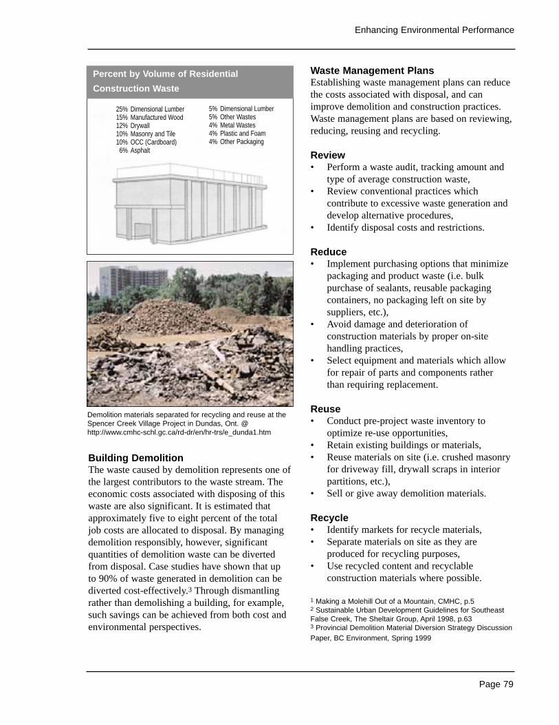
Page 79
Enhancing Environmental Performance
Building DemolitionThe waste caused by demolition represents one ofthe largest contributors to the waste stream. Theeconomic costs associated with disposing of thiswaste are also significant. It is estimated thatapproximately five to eight percent of the totaljob costs are allocated to disposal. By managingdemolition responsibly, however, significantquantities of demolition waste can be divertedfrom disposal. Case studies have shown that up to 90% of waste generated in demolition can bediverted cost-effectively.3 Through dismantlingrather than demolishing a building, for example,such savings can be achieved from both cost andenvironmental perspectives.
Waste Management PlansEstablishing waste management plans can reducethe costs associated with disposal, and canimprove demolition and construction practices.Waste management plans are based on reviewing,reducing, reusing and recycling.
Review• Perform a waste audit, tracking amount and
type of average construction waste,• Review conventional practices which
contribute to excessive waste generation anddevelop alternative procedures,
• Identify disposal costs and restrictions.
Reduce• Implement purchasing options that minimize
packaging and product waste (i.e. bulkpurchase of sealants, reusable packagingcontainers, no packaging left on site bysuppliers, etc.),
• Avoid damage and deterioration ofconstruction materials by proper on-sitehandling practices,
• Select equipment and materials which allowfor repair of parts and components rather than requiring replacement.
Reuse• Conduct pre-project waste inventory to
optimize re-use opportunities,• Retain existing buildings or materials,• Reuse materials on site (i.e. crushed masonry
for driveway fill, drywall scraps in interiorpartitions, etc.),
• Sell or give away demolition materials.
Recycle• Identify markets for recycle materials,• Separate materials on site as they are
produced for recycling purposes,• Use recycled content and recyclable
construction materials where possible.
1 Making a Molehill Out of a Mountain, CMHC, p.52 Sustainable Urban Development Guidelines for SoutheastFalse Creek, The Sheltair Group, April 1998, p.633 Provincial Demolition Material Diversion Strategy DiscussionPaper, BC Environment, Spring 1999
Percent by Volume of Residential
Construction Waste
Demolition materials separated for recycling and reuse at theSpencer Creek Village Project in Dundas, Ont. @http://www.cmhc-schl.gc.ca/rd-dr/en/hr-trs/e_dunda1.htm
25% Dimensional Lumber15% Manufactured Wood12% Drywall10% Masonry and Tile10% OCC (Cardboard)6% Asphalt
5% Dimensional Lumber5% Other Wastes4% Metal Wastes4% Plastic and Foam4% Other Packaging

Page 80
Healthy High-Rise
RETROFIT OPPORTUNITIES
The focus of retrofit opportunities in terms ofsolid waste is on ensuring the most appropriatefacilities for collecting, storing and handlingwaste for recycling and composting. Although thebest opportunities for providing dedicated wastemanagement spaces exist during initial design and construction, the conversion of interior andexterior spaces to perform waste handlingfunctions is possible. While it is unlikely that a building will be retrofitted with recyclingcollection chutes or shafts, it is possible thatspaces can be modified to permit the separation,collection and storage of materials for recyclingand / or composting. These spaces should be largeenough to accommodate a significant diversionrate, and should be easily accessible to occupantsand to custodial staff.
Sources of Information
• Making a Molehill Out of A Mountain,CMHC, 1991.
• Challenge: Reducing ResidentialConstruction Waste, CMHC brochure.
• Santa Monica Green Building Design &Construction Guidelines, The Sheltair Groupet.al, 1999
• Green Building Challenge (GBC)’98Assessment Manual: Multi-Unit ResidentialBuildings, Cole, Raymond & Larsson, Nils,Buildings Group, Natural ResourcesCanada,1998. @ http://www.greenbuilding.ca
• Sustainable Urban Development Guidelinesfor Southeast False Creek, The SheltairGroup Inc., 1998.
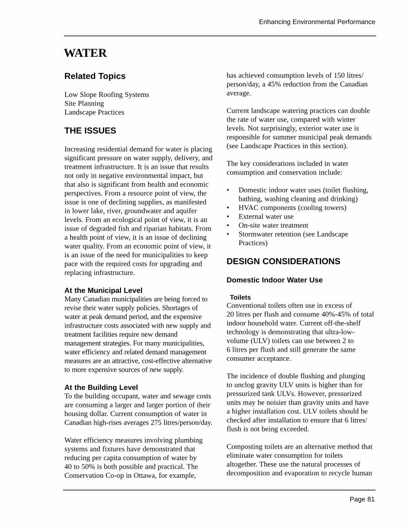
Page 81
Enhancing Environmental Performance
Related Topics
Low Slope Roofing SystemsSite PlanningLandscape Practices
THE ISSUES
Increasing residential demand for water is placingsignificant pressure on water supply, delivery, andtreatment infrastructure. It is an issue that resultsnot only in negative environmental impact, butthat also is significant from health and economicperspectives. From a resource point of view, theissue is one of declining supplies, as manifestedin lower lake, river, groundwater and aquiferlevels. From an ecological point of view, it is anissue of degraded fish and riparian habitats. Froma health point of view, it is an issue of decliningwater quality. From an economic point of view, itis an issue of the need for municipalities to keeppace with the required costs for upgrading andreplacing infrastructure.
At the Municipal LevelMany Canadian municipalities are being forced torevise their water supply policies. Shortages ofwater at peak demand period, and the expensiveinfrastructure costs associated with new supply andtreatment facilities require new demandmanagement strategies. For many municipalities,water efficiency and related demand managementmeasures are an attractive, cost-effective alternativeto more expensive sources of new supply.
At the Building LevelTo the building occupant, water and sewage costsare consuming a larger and larger portion of theirhousing dollar. Current consumption of water inCanadian high-rises averages 275 litres/person/day.
Water efficiency measures involving plumbingsystems and fixtures have demonstrated thatreducing per capita consumption of water by 40 to 50% is both possible and practical. TheConservation Co-op in Ottawa, for example,
has achieved consumption levels of 150 litres/person/day, a 45% reduction from the Canadianaverage.
Current landscape watering practices can doublethe rate of water use, compared with winterlevels. Not surprisingly, exterior water use isresponsible for summer municipal peak demands(see Landscape Practices in this section).
The key considerations included in waterconsumption and conservation include:
• Domestic indoor water uses (toilet flushing,bathing, washing cleaning and drinking)
• HVAC components (cooling towers)• External water use• On-site water treatment• Stormwater retention (see Landscape
Practices)
DESIGN CONSIDERATIONS
Domestic Indoor Water Use
ToiletsConventional toilets often use in excess of 20 litres per flush and consume 40%-45% of totalindoor household water. Current off-the-shelftechnology is demonstrating that ultra-low-volume (ULV) toilets can use between 2 to 6 litres per flush and still generate the sameconsumer acceptance.
The incidence of double flushing and plunging to unclog gravity ULV units is higher than forpressurized tank ULVs. However, pressurizedunits may be noisier than gravity units and have a higher installation cost. ULV toilets should bechecked after installation to ensure that 6 litres/flush is not being exceeded.
Composting toilets are an alternative method thateliminate water consumption for toiletsaltogether. These use the natural processes ofdecomposition and evaporation to recycle human
WATER
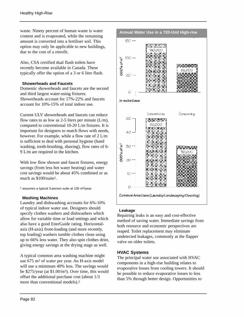
Page 82
Healthy High-Rise
waste. Ninety percent of human waste is watercontent and is evaporated, while the remainingamount is converted into a fertiliser soil. Thisoption may only be applicable to new buildings,due to the cost of a retrofit.
Also, CSA certified dual flush toilets haverecently become available in Canada. Thesetypically offer the option of a 3 or 6 litre flush.
Showerheads and Faucets Domestic showerheads and faucets are the secondand third largest water-using fixtures.Showerheads account for 17%-22% and faucetsaccount for 10%-15% of total indoor use.
Current ULV showerheads and faucets can reduceflow rates to as low as 2-5 liters per minute (L/m),compared to conventional 10-20 L/m fixtures. It isimportant for designers to match flows with needs,however. For example, while a flow rate of 2 L/mis sufficient to deal with personal hygiene (handwashing, tooth-brushing, shaving), flow rates of 6-9 L/m are required in the kitchen.
With low flow shower and faucet fixtures, energysavings (from less hot water heating) and watercost savings would be about 45% combined or asmuch as $100/suite1.
1 assumes a typical 3-person suite at 135 m3/year.
Washing MachinesLaundry and dishwashing accounts for 6%-10%of typical indoor water use. Designers shouldspecify clothes washers and dishwashers whichallow for variable time or load settings and whichalso have a good EnerGuide rating. Horizontal-axis (H-axis) front-loading (and more recently,top loading) washers tumble clothes clean usingup to 66% less water. They also spin clothes drier,giving energy savings at the drying stage as well.
A typical common area washing machine mightuse 675 m3 of water per year. An H-axis modelwill use a minimum 40% less. The savings wouldbe $275/year (at $1.00/m3). Over time, this wouldoffset the additional purchase cost (about 1/3more than conventional models).2
LeakageRepairing leaks is an easy and cost-effectivemethod of saving water. Immediate savings fromboth resource and economic perspectives arereaped. Toilet replacement may eliminateundetected leakages, commonly at the flappervalve on older toilets.
HVAC SystemsThe principal water use associated with HVACcomponents in a high-rise building relates toevaporative losses from cooling towers. It shouldbe possible to reduce evaporative losses to lessthan 5% through better design. Opportunities to
Annual Water Use in a 720-Unit High-rise
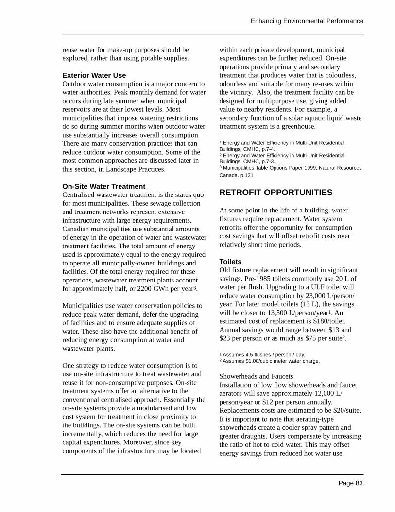
Page 83
Enhancing Environmental Performance
reuse water for make-up purposes should beexplored, rather than using potable supplies.
Exterior Water UseOutdoor water consumption is a major concern towater authorities. Peak monthly demand for wateroccurs during late summer when municipalreservoirs are at their lowest levels. Mostmunicipalities that impose watering restrictionsdo so during summer months when outdoor wateruse substantially increases overall consumption.There are many conservation practices that canreduce outdoor water consumption. Some of themost common approaches are discussed later inthis section, in Landscape Practices.
On-Site Water Treatment Centralised wastewater treatment is the status quofor most municipalities. These sewage collectionand treatment networks represent extensiveinfrastructure with large energy requirements.Canadian municipalities use substantial amountsof energy in the operation of water and wastewatertreatment facilities. The total amount of energyused is approximately equal to the energy requiredto operate all municipally-owned buildings andfacilities. Of the total energy required for theseoperations, wastewater treatment plants accountfor approximately half, or 2200 GWh per year3.
Municipalities use water conservation policies toreduce peak water demand, defer the upgradingof facilities and to ensure adequate supplies ofwater. These also have the additional benefit ofreducing energy consumption at water andwastewater plants.
One strategy to reduce water consumption is touse on-site infrastructure to treat wastewater andreuse it for non-consumptive purposes. On-sitetreatment systems offer an alternative to theconventional centralised approach. Essentially theon-site systems provide a modularised and lowcost system for treatment in close proximity tothe buildings. The on-site systems can be builtincrementally, which reduces the need for largecapital expenditures. Moreover, since keycomponents of the infrastructure may be located
within each private development, municipalexpenditures can be further reduced. On-siteoperations provide primary and secondarytreatment that produces water that is colourless,odourless and suitable for many re-uses withinthe vicinity. Also, the treatment facility can bedesigned for multipurpose use, giving addedvalue to nearby residents. For example, asecondary function of a solar aquatic liquid wastetreatment system is a greenhouse.
1 Energy and Water Efficiency in Multi-Unit ResidentialBuildings, CMHC, p.7-4.2 Energy and Water Efficiency in Multi-Unit ResidentialBuildings, CMHC, p.7-3.3 Municipalities Table Options Paper 1999, Natural ResourcesCanada, p.131
RETROFIT OPPORTUNITIES
At some point in the life of a building, waterfixtures require replacement. Water systemretrofits offer the opportunity for consumptioncost savings that will offset retrofit costs overrelatively short time periods.
ToiletsOld fixture replacement will result in significantsavings. Pre-1985 toilets commonly use 20 L ofwater per flush. Upgrading to a ULF toilet willreduce water consumption by 23,000 L/person/year. For later model toilets (13 L), the savingswill be closer to 13,500 L/person/year1. Anestimated cost of replacement is $180/toilet.Annual savings would range between $13 and$23 per person or as much as $75 per suite2.
1 Assumes 4.5 flushes / person / day.2 Assumes $1.00/cubic meter water charge.
Showerheads and FaucetsInstallation of low flow showerheads and faucetaerators will save approximately 12,000 L/person/year or $12 per person annually.Replacements costs are estimated to be $20/suite.It is important to note that aerating-typeshowerheads create a cooler spray pattern andgreater draughts. Users compensate by increasingthe ratio of hot to cold water. This may offsetenergy savings from reduced hot water use.

Page 84
Healthy High-Rise
Washing MachinesWashing Machines can be adjusted to allow coldrinses only. Modifications to rinse cycle watertemperatures will average $100 per machine. Interms of energy cost savings, payback will be inthe order of 6 to 12 months. Quaified personnelare required to make machine modifications.
LeakageA leak of one drop per second will amount to 9,000 liters per year. This represents $9 per fixtureand $45 for hot water fixtures. Regular maintenanceof water fixtures will reduce leakage and minimizemunicipal water and sewerage service and energycosts. Kitchen and bathroom taps should be replacedevery two years. Replacement costs areapproximately $5 per fixture.
Installation of washerless taps can be undertakenas old tap sets require replacement. These willsignificantly reduce labour costs for regularwasher replacement. They typically cost 30-50%more than conventional taps.
Toilet replacement may eliminate undetectedleakages, commonly at the flapper valve on oldertoilets.
Exterior Water UseFor the typical high-rise lot, rain sensorequipment may cost approximately $150. Savingsfrom water conservation would be 12-15% or$125 per season (at $1.00/m3). Simple paybackwould be 1.5 years.
Sources of Information
• Water: No time to waste - A Consumer’sGuide to Water Conservation , EnvironmentCanada 1995.
• A Survey of Ultra-low Flush Toilet Users.Prepared for the Los Angeles Dept.; of Waterand Power by the Wirthlin Group, 1995.
• The Potential for Water EfficiencyImprovement in Multi-Family ResidentialBuildings in Canada, CMHC, 1997.
• The Performance of Ultra-Low-Volume FlushToilets in Phoenix, Journal of American WaterWorks Association (AWWA), Vol. 81, No. 3,Anderson, D.L. and Siegrist, R.L., 1989.
• Residential Water Conservation; A Review ofProducts, Processes and Practices, CMHC,1991.
• An Ecological Approach to Site andSubdivision Design, Alberta MunicipalAffairs, 1993
• Energy and Water Efficiency in Multi-UnitResidential Buildings, Technical Manual,CMHC, 2000.
• Case Studies of Potential Applications ofInnovative Residential Water WastewaterTechnologies , CMHC, 1999.
• Water Quality Guidelines and WaterMonitoring Tools for Residential WaterReuse. CMHC,1999.
• Innovative Water and WastewaterManagement, CMHC, 1998.
• An Application Guide for Water ReuseSystems, CMHC,1998.
• Regulatory Barriers to On-site Water Reuse,CMHC, 1998.
• CMHC Water Conservation Page @http://www.cmhc-schl.gc.ca/rd-dr/en/water-eau/index.html
Page 85
Enhancing Environmental Performance
Related Topics
Low Slope Roofing SystemsSpace Heating and Air ConditioningSite PlanningWater
THE ISSUES
Approriate and well-considered landscapepractices offer designers the opportunity toachieve increased levels of occupant comfort aswell as cost savings through reduced resourceconsumption. Consideration should be given towater conservation, seasonally appropriate designdecisions and stormwater management.
Across Canada, water use more than doubles inthe summer months. Most of this increase is dueto the watering of lawns and gardens, car washingand the filling of swimming pools. This is typicalof suburban areas, but highrise waterconsumption also contributes to increasedsummer water use. This is the case for buildingswith extensive landscape watering requirements.Through water conservation practices inlandscape design, this phenomena can be reduced.
Energy consumption in highrise residentialbuildings can also be reduced through thoughtfullandscape design practices. Plants provide the mosteconomic means of modifying microclimate arounda building, and represent a small investment forlarge energy savings. Appropriate and well-placedplants will have an effect upon energyconsumption. Other devices such as landscapestructures and site grading are also available to thelandscape architect, and when employed correctly,can result in further energy savings.
Stormwater management represents a significantcost to municipalities, via infrastructure requiredto transport and treat run-off. It also represents acost to the environment through non-point sourcepollution. This is the transfer of pollutants fromroadways and parking lots directly to water bodies
via run-off. The landscape architect as well as thecivil engineer are able to offset these costs byusing appropriate best management practices forstormwater management. Many on-site devicesare available for slowing and filtering stormwater.Other strategies include minimizing the amount of run-off from a site as well as re-using it.
Key issues considered in this section include:
• Water-efficient landscape practices• Energy-efficient landscape practices for
Summer and Winter• Stormwater management practices.
DESIGN CONSIDERATIONS
Water-Efficient Landscape PracticesReducing watering requirements by at least 50%is achievable when specifying a water-efficientlandscape. There are many water conservationpractices that can achieve such reductions.
Rainfall Storage and ReuseRain diverted through downspouts into storagedevices (cisterns, rain-barrels) can be used forirrigation. The “Rainfall Capture Potential” tableprovides an estimate of the rainwater volumecollectable from typical high-rise buildings acrossCanada. Storage devices range in size. TheMountain Equipment Co-op Building in Ottawahas a rain storage container of 65,000 liters. It is2.4 m (8 ft) in diameter and 6.0 m (20 ft) high.
Considering that high-rise buildings can consumean average of 13,000,000 litres annually1, raincollection for indoor use does not seemsignificant. However, rain collection would likelymeet a high-rise building’s irrigationrequirements. Rain collection for irrigation helpsto lower water demand during summer monthswhen consumption is at its highest.
Locally Hardy PlantsMatch plant species to their local conditions.Locally hardy plant species, such as native plants,
LANDSCAPE PRACTICES
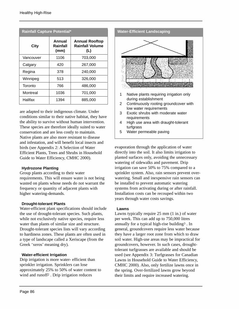
Page 86
Healthy High-Rise
are adapted to their indigenous climate. Underconditions similar to their native habitat, they havethe ability to survive without human intervention.These species are therefore ideally suited to waterconservation and are less costly to maintain.Native plants are also more resistant to diseaseand infestation, and will benefit local insects andbirds (see Appendix 2: A Selection of WaterEfficient Plants, Trees and Shrubs in HouseholdGuide to Water Efficiency, CMHC 2000).
Hydrozone PlantingGroup plants according to their waterrequirements. This will ensure water is not beingwasted on plants whose needs do not warrant thefrequency or quantity of adjacent plants withhigher watering-demands.
Drought-tolerant PlantsWater-efficient plant specifications should includethe use of drought-tolerant species. Such plants,while not exclusively native species, require lesswater than plants of similar size and structure.Drought-tolerant species lists will vary accordingto hardiness zones. These plants are often used ina type of landscape called a Xeriscape (from theGreek ‘xeros’ meaning dry).
Water-efficient IrrigationDrip irrigation is more water- efficient thansprinkler irrigation. Sprinklers can loseapproximately 25% to 50% of water content towind and runoff2 . Drip irrigation reduces
evaporation through the application of waterdirectly into the soil. It also limits irrigation toplanted surfaces only, avoiding the unnecessarywatering of sidewalks and pavement. Dripirrigation can save 50% to 75% compared to asprinkler system. Also, rain sensors prevent over-watering. Small and inexpensive rain sensors canbe installed to prevent automatic wateringsystems from activating during or after rainfall.Installation costs can be recouped within twoyears through water costs savings.
LawnsLawns typically require 25 mm (1 in.) of waterper week. This can add up to 750,000 litresannually for a typical high-rise building3 . Ingeneral, groundcovers require less water becausethey have a larger root zone from which to drawsoil water. High-use areas may be impractical forgroundcovers, however. In such cases, drought-tolerant turfgrasses are available and should beused (see Appendix 3: Turfgrasses for CanadianLawns in Household Guide to Water Efficiency,CMHC 2000). Also, only fertilize lawns once inthe spring. Over-fertilized lawns grow beyondtheir limits and require increased watering.
Rainfall Capture Potential* Water-Efficient Landscaping
Annual Annual RooftopCity Rainfall Rainfall Volume
(mm) (L)
Vancouver 1106 703,000
Calgary 420 267,000
Regina 378 240,000
Winnipeg 513 326,000
Toronto 766 486,000
Montreal 1036 701,000
Halifax 1394 885,0001 Native plants requiring irrigation only
during establishment2 Continuously rooting groundcover with
low water requirements3 Exotic shrubs with moderate water
requirements4 High use area with draught-tolerant
turfgrass5 Water permeable paving
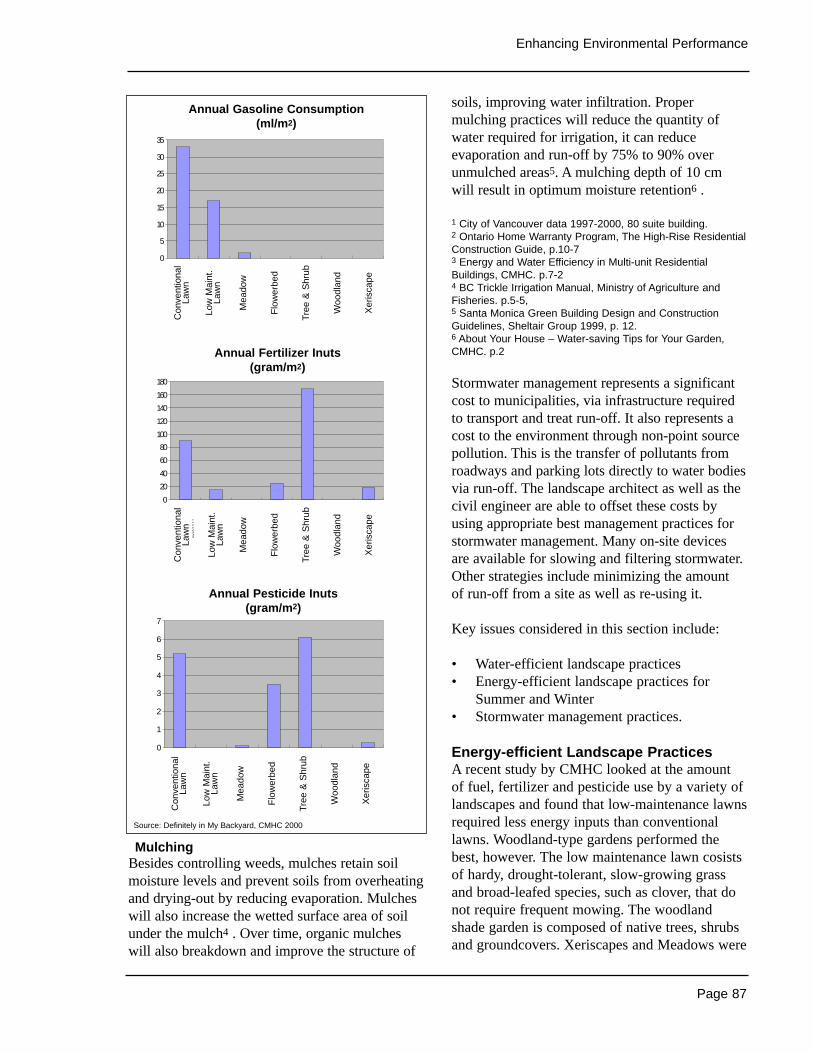
Page 87
Enhancing Environmental Performance
MulchingBesides controlling weeds, mulches retain soilmoisture levels and prevent soils from overheatingand drying-out by reducing evaporation. Mulcheswill also increase the wetted surface area of soilunder the mulch4 . Over time, organic mulcheswill also breakdown and improve the structure of
soils, improving water infiltration. Propermulching practices will reduce the quantity ofwater required for irrigation, it can reduceevaporation and run-off by 75% to 90% overunmulched areas5. A mulching depth of 10 cmwill result in optimum moisture retention6 .
1 City of Vancouver data 1997-2000, 80 suite building.2 Ontario Home Warranty Program, The High-Rise ResidentialConstruction Guide, p.10-73 Energy and Water Efficiency in Multi-unit ResidentialBuildings, CMHC. p.7-24 BC Trickle Irrigation Manual, Ministry of Agriculture andFisheries. p.5-5,5 Santa Monica Green Building Design and ConstructionGuidelines, Sheltair Group 1999, p. 12.6 About Your House – Water-saving Tips for Your Garden,CMHC. p.2
Stormwater management represents a significantcost to municipalities, via infrastructure requiredto transport and treat run-off. It also represents acost to the environment through non-point sourcepollution. This is the transfer of pollutants fromroadways and parking lots directly to water bodiesvia run-off. The landscape architect as well as thecivil engineer are able to offset these costs byusing appropriate best management practices forstormwater management. Many on-site devicesare available for slowing and filtering stormwater.Other strategies include minimizing the amount of run-off from a site as well as re-using it.
Key issues considered in this section include:
• Water-efficient landscape practices• Energy-efficient landscape practices for
Summer and Winter• Stormwater management practices.
Energy-efficient Landscape PracticesA recent study by CMHC looked at the amount of fuel, fertilizer and pesticide use by a variety oflandscapes and found that low-maintenance lawnsrequired less energy inputs than conventionallawns. Woodland-type gardens performed thebest, however. The low maintenance lawn cosistsof hardy, drought-tolerant, slow-growing grassand broad-leafed species, such as clover, that donot require frequent mowing. The woodlandshade garden is composed of native trees, shrubsand groundcovers. Xeriscapes and Meadows were
0
20
40
60
80
100
120
140
160
180
Con
vent
iona
lLa
wn
Low
Mai
n.La
wn
Mea
dow
Flo
wer
bed
Tre
e &
Shr
ub
Woo
dlan
d
Xer
isca
pe
0
5
10
15
20
25
30
35
Con
vent
iona
lLa
wn
Low
Mai
nt.
Law
n
Mea
dow
Flo
wer
bed
Tre
e &
Shr
ub
Woo
dlan
d
Xer
isca
pe
0
1
2
3
4
5
6
7
Con
vent
iona
lLa
wn
Low
Mai
n.La
wn
Mea
dow
Flo
wer
bed
Tre
e &
Shr
ub
Woo
dlan
d
Xer
isca
pe
Annual Gasoline Consumption(ml/m2)
Annual Fertilizer Inputs(gram/m2)
Annual Pesticide Inputs(gram/m2)
Annual Fertilizer Inuts(gram/m2)
Annual Gasoline Consumption(ml/m2)
Annual Pesticide Inuts(gram/m2)
Con
vent
iona
lLa
wn
Low
Mai
nt.
Law
n
Mea
dow
Flo
wer
bed
Tree
& S
hrub
Woo
dlan
d
Xer
isca
pe
Con
vent
iona
lLa
wn
Low
Mai
nt.
Law
n
Mea
dow
Flo
wer
bed
Tree
& S
hrub
Woo
dlan
d
Xer
isca
pe
Con
vent
iona
lLa
wn
Low
Mai
nt.
Law
n
Mea
dow
Flo
wer
bed
Tree
& S
hrub
Woo
dlan
d
Xer
isca
pe
Source: Definitely in My Backyard, CMHC 2000
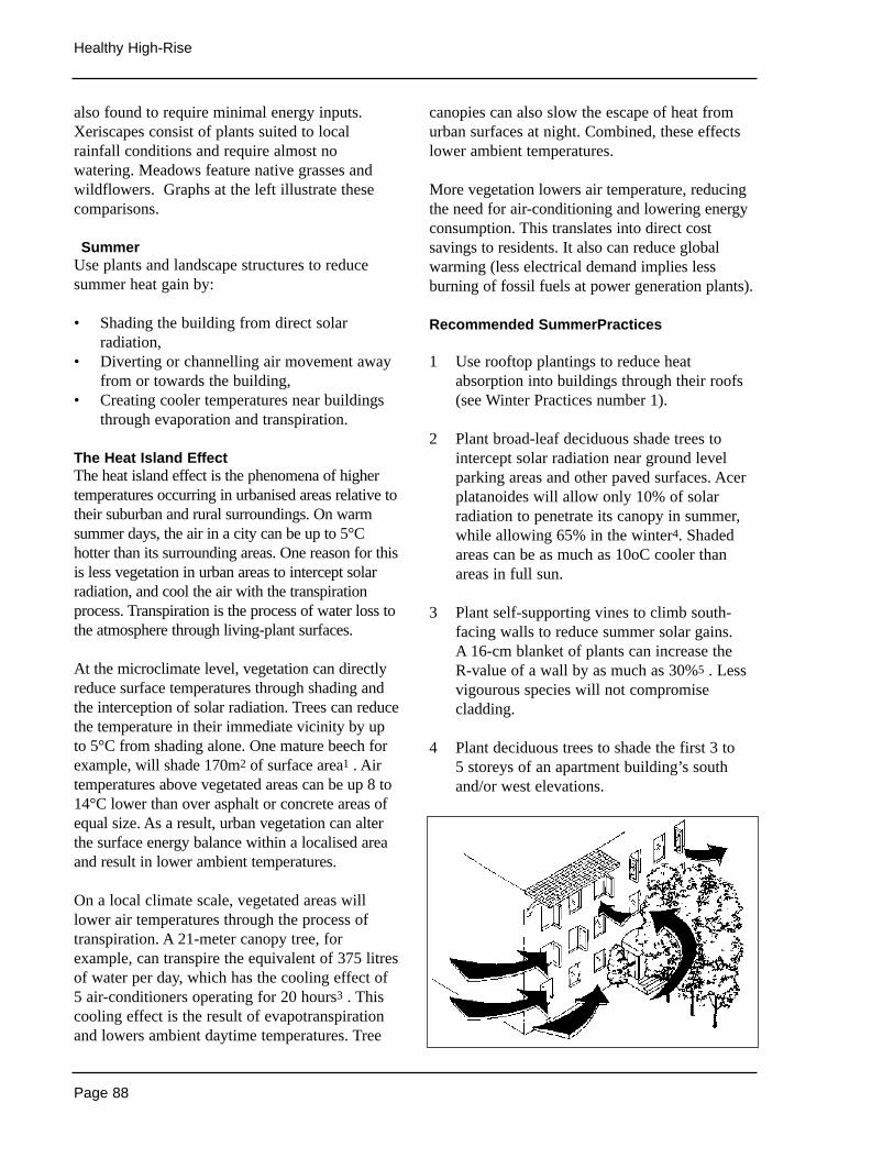
Page 88
Healthy High-Rise
also found to require minimal energy inputs.Xeriscapes consist of plants suited to localrainfall conditions and require almost nowatering. Meadows feature native grasses andwildflowers. Graphs at the left illustrate thesecomparisons.
SummerUse plants and landscape structures to reducesummer heat gain by:
• Shading the building from direct solarradiation,
• Diverting or channelling air movement awayfrom or towards the building,
• Creating cooler temperatures near buildingsthrough evaporation and transpiration.
The Heat Island EffectThe heat island effect is the phenomena of highertemperatures occurring in urbanised areas relative totheir suburban and rural surroundings. On warmsummer days, the air in a city can be up to 5°Chotter than its surrounding areas. One reason for thisis less vegetation in urban areas to intercept solarradiation, and cool the air with the transpirationprocess. Transpiration is the process of water loss tothe atmosphere through living-plant surfaces.
At the microclimate level, vegetation can directlyreduce surface temperatures through shading andthe interception of solar radiation. Trees can reducethe temperature in their immediate vicinity by upto 5°C from shading alone. One mature beech forexample, will shade 170m2 of surface area1 . Airtemperatures above vegetated areas can be up 8 to14°C lower than over asphalt or concrete areas ofequal size. As a result, urban vegetation can alterthe surface energy balance within a localised areaand result in lower ambient temperatures.
On a local climate scale, vegetated areas willlower air temperatures through the process oftranspiration. A 21-meter canopy tree, forexample, can transpire the equivalent of 375 litresof water per day, which has the cooling effect of5 air-conditioners operating for 20 hours3 . Thiscooling effect is the result of evapotranspirationand lowers ambient daytime temperatures. Tree
canopies can also slow the escape of heat fromurban surfaces at night. Combined, these effectslower ambient temperatures.
More vegetation lowers air temperature, reducingthe need for air-conditioning and lowering energyconsumption. This translates into direct costsavings to residents. It also can reduce globalwarming (less electrical demand implies lessburning of fossil fuels at power generation plants).
Recommended SummerPractices
1 Use rooftop plantings to reduce heatabsorption into buildings through their roofs(see Winter Practices number 1).
2 Plant broad-leaf deciduous shade trees tointercept solar radiation near ground levelparking areas and other paved surfaces. Acerplatanoides will allow only 10% of solarradiation to penetrate its canopy in summer,while allowing 65% in the winter4. Shadedareas can be as much as 10oC cooler thanareas in full sun.
3 Plant self-supporting vines to climb south-facing walls to reduce summer solar gains. A 16-cm blanket of plants can increase the R-value of a wall by as much as 30%5 . Lessvigourous species will not compromisecladding.
4 Plant deciduous trees to shade the first 3 to 5 storeys of an apartment building’s southand/or west elevations.
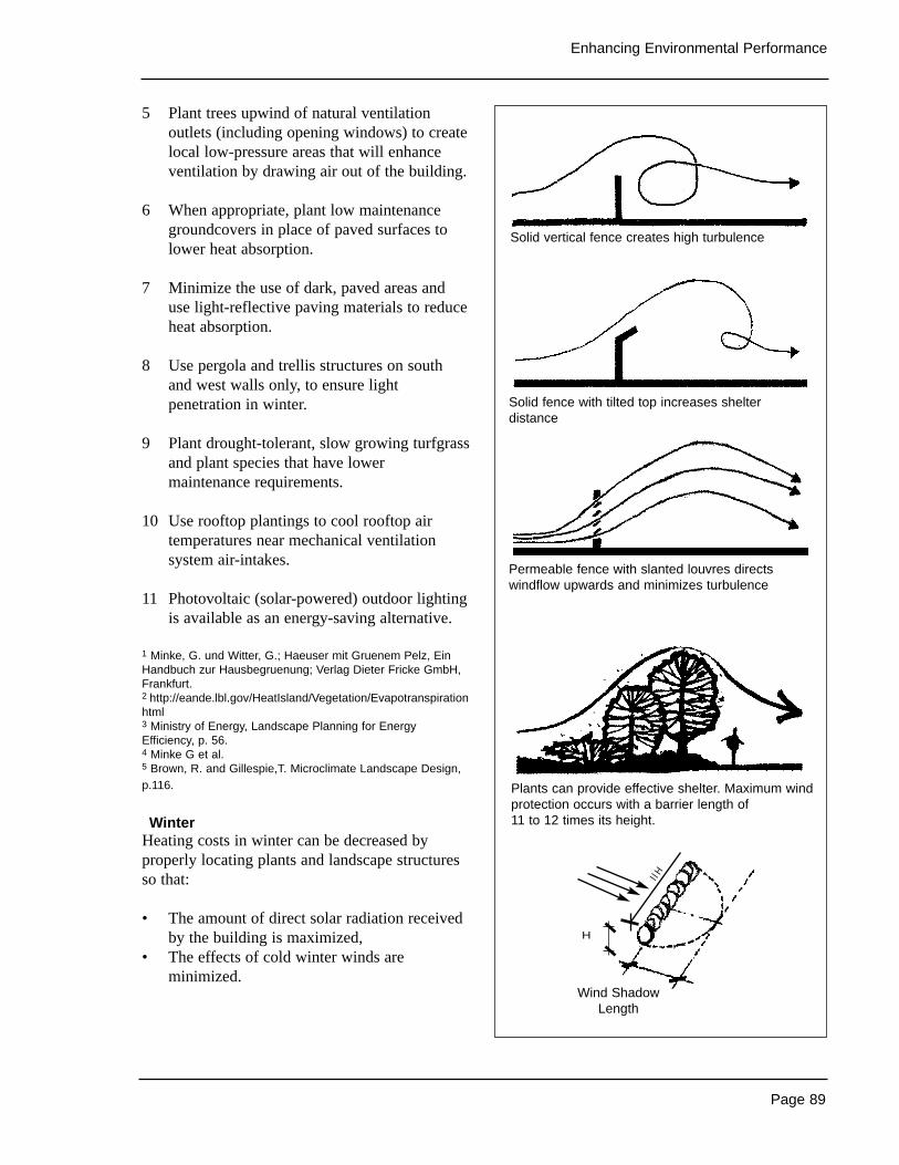
Page 89
Enhancing Environmental Performance
5 Plant trees upwind of natural ventilationoutlets (including opening windows) to createlocal low-pressure areas that will enhanceventilation by drawing air out of the building.
6 When appropriate, plant low maintenancegroundcovers in place of paved surfaces tolower heat absorption.
7 Minimize the use of dark, paved areas anduse light-reflective paving materials to reduceheat absorption.
8 Use pergola and trellis structures on southand west walls only, to ensure lightpenetration in winter.
9 Plant drought-tolerant, slow growing turfgrassand plant species that have lowermaintenance requirements.
10 Use rooftop plantings to cool rooftop airtemperatures near mechanical ventilationsystem air-intakes.
11 Photovoltaic (solar-powered) outdoor lightingis available as an energy-saving alternative.
1 Minke, G. und Witter, G.; Haeuser mit Gruenem Pelz, EinHandbuch zur Hausbegruenung; Verlag Dieter Fricke GmbH,Frankfurt.2 http://eande.lbl.gov/HeatIsland/Vegetation/Evapotranspirationhtml3 Ministry of Energy, Landscape Planning for EnergyEfficiency, p. 56.4 Minke G et al.5 Brown, R. and Gillespie,T. Microclimate Landscape Design,p.116.
WinterHeating costs in winter can be decreased byproperly locating plants and landscape structuresso that:
• The amount of direct solar radiation receivedby the building is maximized,
• The effects of cold winter winds areminimized.
Solid vertical fence creates high turbulence
Solid fence with tilted top increases shelterdistance
Permeable fence with slanted louvres directswindflow upwards and minimizes turbulence
Plants can provide effective shelter. Maximum windprotection occurs with a barrier length of 11 to 12 times its height.
Wind ShadowLength
l lH
H
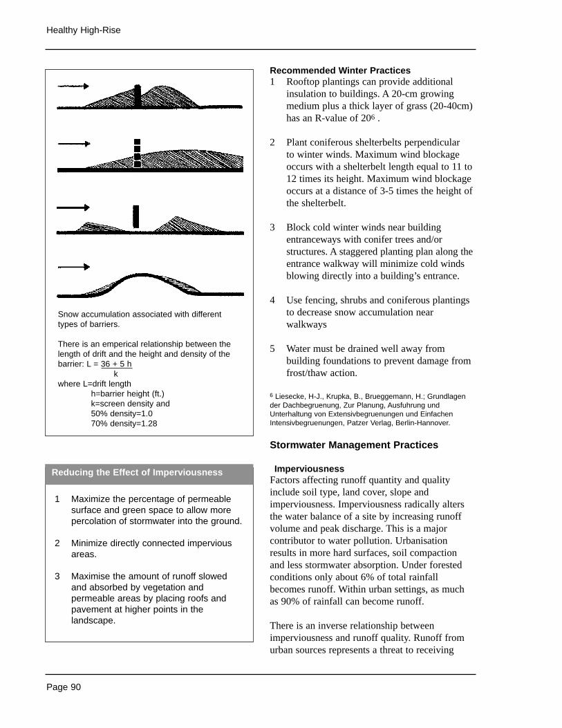
Reducing the Effect of Imperviousness
Page 90
Healthy High-Rise
Recommended Winter Practices1 Rooftop plantings can provide additional
insulation to buildings. A 20-cm growingmedium plus a thick layer of grass (20-40cm)has an R-value of 206 .
2 Plant coniferous shelterbelts perpendicular to winter winds. Maximum wind blockageoccurs with a shelterbelt length equal to 11 to12 times its height. Maximum wind blockageoccurs at a distance of 3-5 times the height ofthe shelterbelt.
3 Block cold winter winds near buildingentranceways with conifer trees and/orstructures. A staggered planting plan along theentrance walkway will minimize cold windsblowing directly into a building’s entrance.
4 Use fencing, shrubs and coniferous plantingsto decrease snow accumulation nearwalkways
5 Water must be drained well away frombuilding foundations to prevent damage fromfrost/thaw action.
6 Liesecke, H-J., Krupka, B., Brueggemann, H.; Grundlagender Dachbegruenung, Zur Planung, Ausfuhrung undUnterhaltung von Extensivbegruenungen und EinfachenIntensivbegruenungen, Patzer Verlag, Berlin-Hannover.
Stormwater Management Practices
ImperviousnessFactors affecting runoff quantity and qualityinclude soil type, land cover, slope andimperviousness. Imperviousness radically altersthe water balance of a site by increasing runoffvolume and peak discharge. This is a majorcontributor to water pollution. Urbanisationresults in more hard surfaces, soil compactionand less stormwater absorption. Under forestedconditions only about 6% of total rainfallbecomes runoff. Within urban settings, as muchas 90% of rainfall can become runoff.
There is an inverse relationship betweenimperviousness and runoff quality. Runoff fromurban sources represents a threat to receiving
1 Maximize the percentage of permeablesurface and green space to allow morepercolation of stormwater into the ground.
2 Minimize directly connected imperviousareas.
3 Maximise the amount of runoff slowedand absorbed by vegetation andpermeable areas by placing roofs andpavement at higher points in thelandscape.
Snow accumulation associated with differenttypes of barriers.
There is an emperical relationship between thelength of drift and the height and density of thebarrier: L = 36 + 5 h
kwhere L=drift length
h=barrier height (ft.)k=screen density and50% density=1.070% density=1.28
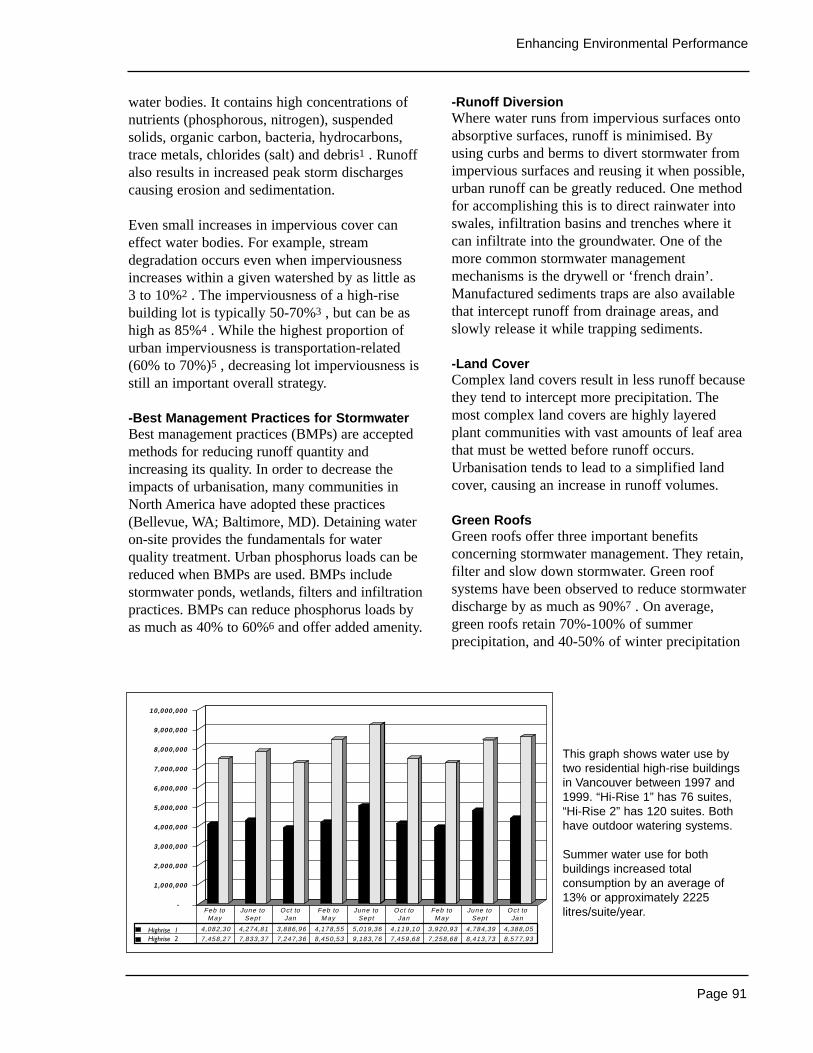
Page 91
Enhancing Environmental Performance
water bodies. It contains high concentrations ofnutrients (phosphorous, nitrogen), suspendedsolids, organic carbon, bacteria, hydrocarbons,trace metals, chlorides (salt) and debris1 . Runoffalso results in increased peak storm dischargescausing erosion and sedimentation.
Even small increases in impervious cover caneffect water bodies. For example, streamdegradation occurs even when imperviousnessincreases within a given watershed by as little as3 to 10%2 . The imperviousness of a high-risebuilding lot is typically 50-70%3 , but can be ashigh as 85%4 . While the highest proportion ofurban imperviousness is transportation-related(60% to 70%)5 , decreasing lot imperviousness isstill an important overall strategy.
-Best Management Practices for StormwaterBest management practices (BMPs) are acceptedmethods for reducing runoff quantity andincreasing its quality. In order to decrease theimpacts of urbanisation, many communities inNorth America have adopted these practices(Bellevue, WA; Baltimore, MD). Detaining wateron-site provides the fundamentals for waterquality treatment. Urban phosphorus loads can bereduced when BMPs are used. BMPs includestormwater ponds, wetlands, filters and infiltrationpractices. BMPs can reduce phosphorus loads byas much as 40% to 60%6 and offer added amenity.
-Runoff Diversion Where water runs from impervious surfaces ontoabsorptive surfaces, runoff is minimised. Byusing curbs and berms to divert stormwater fromimpervious surfaces and reusing it when possible,urban runoff can be greatly reduced. One methodfor accomplishing this is to direct rainwater intoswales, infiltration basins and trenches where itcan infiltrate into the groundwater. One of themore common stormwater managementmechanisms is the drywell or ‘french drain’.Manufactured sediments traps are also availablethat intercept runoff from drainage areas, andslowly release it while trapping sediments.
-Land CoverComplex land covers result in less runoff becausethey tend to intercept more precipitation. Themost complex land covers are highly layeredplant communities with vast amounts of leaf areathat must be wetted before runoff occurs.Urbanisation tends to lead to a simplified landcover, causing an increase in runoff volumes.
Green RoofsGreen roofs offer three important benefitsconcerning stormwater management. They retain,filter and slow down stormwater. Green roofsystems have been observed to reduce stormwaterdischarge by as much as 90%7 . On average,green roofs retain 70%-100% of summerprecipitation, and 40-50% of winter precipitation
-
1 ,000,000
2,000,000
3,000,000
4,000,000
5,000,000
6,000,000
7,000,000
8,000,000
9,000,000
10,000,000
1260 B idwell 4,082,30 4,274,81 3,886,96 4,178,55 5,019,36 4,119,10 3,920,93 4,784,39 4,388,05
1651 Harwood 7,458,27 7,833,37 7,247,36 8,450,53 9,183,76 7,459,68 7,258,68 8,413,73 8,577,93
Feb to M ay
June to Sept
Oct to Jan
Feb to M ay
June to Sept
Oct to Jan
Feb to M ay
June to Sept
Oct to Jan
Highrise 1Highrise 2
This graph shows water use bytwo residential high-rise buildingsin Vancouver between 1997 and1999. “Hi-Rise 1” has 76 suites,“Hi-Rise 2” has 120 suites. Bothhave outdoor watering systems.
Summer water use for bothbuildings increased totalconsumption by an average of13% or approximately 2225litres/suite/year.
Page 92
Healthy High-Rise
that falls on them. A green roof acts as a naturalfilter for discharge that does occur by filtering outheavy metals and nutrients carried by rainwater.Its absorptive quality (10-15 cm of runoffretained with a 20-40 cm layer of growingmedium8 ) also slow downs discharge, reducingthe risk of flooding.
1 Maryland Department of the Environment, MarylandStormwater Design Manual, Vol.1, p.1.42 Chillibeck, B., Urban Drainage Planning and StormwaterManagement, Dept. of Fisheries and Oceans3 Harris and Dines, Time Saver Standards for LandscapeArchitecture, p. 330.234 City of Santa Monica, Report to Council on Urban RunoffReduction, p.6.5 Bay Area Stormwater Management Agencies Association,Start at the Source, p.17.6 Schueler, Tom, The importance of Imperviousness fromWatershed Protection Techniques Vol. 1, No. 3 - Fall 19947 Thompson, W., “Grass-Roofs Movement” in LandscapeArchitecture, May 1998, Vol.88, No. 6, pp.47-51.8 Peck, Callaghan, Kuhn, Bass. Greenbacks from GreenRoofs: Forging a New Industry in Canada. CMHC, 1999. p.28
Sources of Information
• About Your House–Water Saving Tips forYour Lawn and Garden, CMHC 2000
• Start at the Source, Bay Area StormwaterManagement Agencies Association, USA,1997.
• Microclimate Landscape Design, Brown,Robert and Terry Gillsepie. John Wiley &Sons, USA, 1995.
• Definitely in My Backyard–Making the BestChoices for You and the Environment,CMHC, 2000 @ http://www.cmhc-schl.gc.ca/cgi-cmhc/enfrmsite.pl?target=/publications/en/definitely/index.html
• Energy and Water Efficiency in Multi-UnitResidential Design, Draft Version, CMHC,January 1998.
• Energy-Efficient and EnvironmentalLandscaping, Appropriate Solutions, Moffatt,Anne Simon and Marc Schiler. USA, 1993.
• Creating a Prairie Xeriscape: Water-EfficientGardening, Williams, Sara, University ofSaskatchewan Press, Canada, 1998.
• Alternative Stormwater managementpractices for residential projects, CMHC @http://www.cmhc-schl.gc.ca/rd-dr/en/water-eau/stormwater.htm
• Sustainable Landscape Construction,J. William Thompson and Kim Sorvig. IslandPress, Washington DC, 2000.
• Design Guidelines for Green Roofs, @http://www.cmhc-schl.gc.ca/en/imquaf/himu/himu_002.cfm
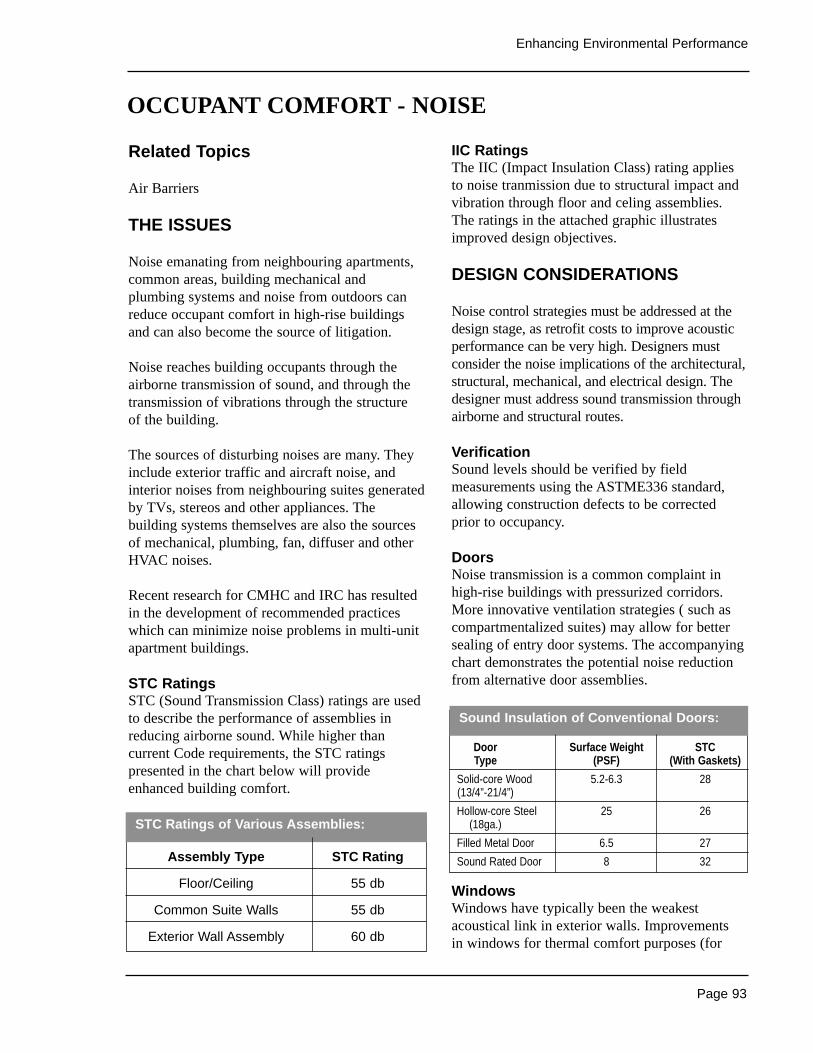
Page 93
Enhancing Environmental Performance
Related Topics
Air Barriers
THE ISSUES
Noise emanating from neighbouring apartments,common areas, building mechanical andplumbing systems and noise from outdoors canreduce occupant comfort in high-rise buildingsand can also become the source of litigation.
Noise reaches building occupants through theairborne transmission of sound, and through thetransmission of vibrations through the structure of the building.
The sources of disturbing noises are many. Theyinclude exterior traffic and aircraft noise, andinterior noises from neighbouring suites generatedby TVs, stereos and other appliances. Thebuilding systems themselves are also the sourcesof mechanical, plumbing, fan, diffuser and otherHVAC noises.
Recent research for CMHC and IRC has resultedin the development of recommended practiceswhich can minimize noise problems in multi-unitapartment buildings.
STC RatingsSTC (Sound Transmission Class) ratings are usedto describe the performance of assemblies inreducing airborne sound. While higher thancurrent Code requirements, the STC ratingspresented in the chart below will provideenhanced building comfort.
IIC RatingsThe IIC (Impact Insulation Class) rating appliesto noise tranmission due to structural impact andvibration through floor and celing assemblies.The ratings in the attached graphic illustratesimproved design objectives.
DESIGN CONSIDERATIONS
Noise control strategies must be addressed at thedesign stage, as retrofit costs to improve acousticperformance can be very high. Designers mustconsider the noise implications of the architectural,structural, mechanical, and electrical design. Thedesigner must address sound transmission throughairborne and structural routes.
VerificationSound levels should be verified by fieldmeasurements using the ASTME336 standard,allowing construction defects to be correctedprior to occupancy.
DoorsNoise transmission is a common complaint inhigh-rise buildings with pressurized corridors.More innovative ventilation strategies ( such ascompartmentalized suites) may allow for bettersealing of entry door systems. The accompanyingchart demonstrates the potential noise reductionfrom alternative door assemblies.
WindowsWindows have typically been the weakestacoustical link in exterior walls. Improvements in windows for thermal comfort purposes (for
STC Ratings of Various Assemblies:
OCCUPANT COMFORT - NOISE
Assembly Type STC Rating
Floor/Ceiling 55 db
Common Suite Walls 55 db
Exterior Wall Assembly 60 db
Sound Insulation of Conventional Doors:
Door Surface Weight STCType (PSF) (With Gaskets)
Solid-core Wood 5.2-6.3 28(13/4”-21/4”)
Hollow-core Steel 25 26(18ga.)
Filled Metal Door 6.5 27
Sound Rated Door 8 32
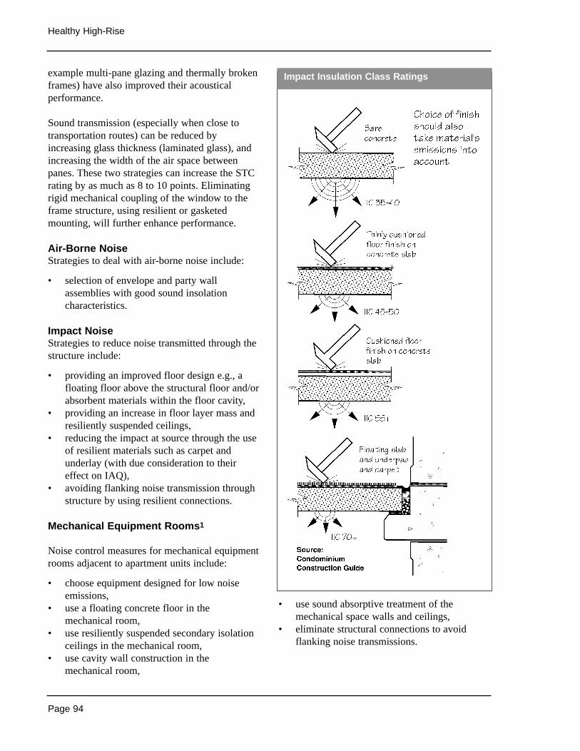
Page 94
Healthy High-Rise
example multi-pane glazing and thermally brokenframes) have also improved their acousticalperformance.
Sound transmission (especially when close totransportation routes) can be reduced byincreasing glass thickness (laminated glass), andincreasing the width of the air space betweenpanes. These two strategies can increase the STCrating by as much as 8 to 10 points. Eliminatingrigid mechanical coupling of the window to theframe structure, using resilient or gasketedmounting, will further enhance performance.
Air-Borne NoiseStrategies to deal with air-borne noise include:
• selection of envelope and party wallassemblies with good sound insolationcharacteristics.
Impact NoiseStrategies to reduce noise transmitted through thestructure include:
• providing an improved floor design e.g., afloating floor above the structural floor and/orabsorbent materials within the floor cavity,
• providing an increase in floor layer mass andresiliently suspended ceilings,
• reducing the impact at source through the useof resilient materials such as carpet andunderlay (with due consideration to theireffect on IAQ),
• avoiding flanking noise transmission throughstructure by using resilient connections.
Mechanical Equipment Rooms1
Noise control measures for mechanical equipmentrooms adjacent to apartment units include:
• choose equipment designed for low noiseemissions,
• use a floating concrete floor in themechanical room,
• use resiliently suspended secondary isolationceilings in the mechanical room,
• use cavity wall construction in themechanical room,
• use sound absorptive treatment of themechanical space walls and ceilings,
• eliminate structural connections to avoidflanking noise transmissions.
Impact Insulation Class Ratings
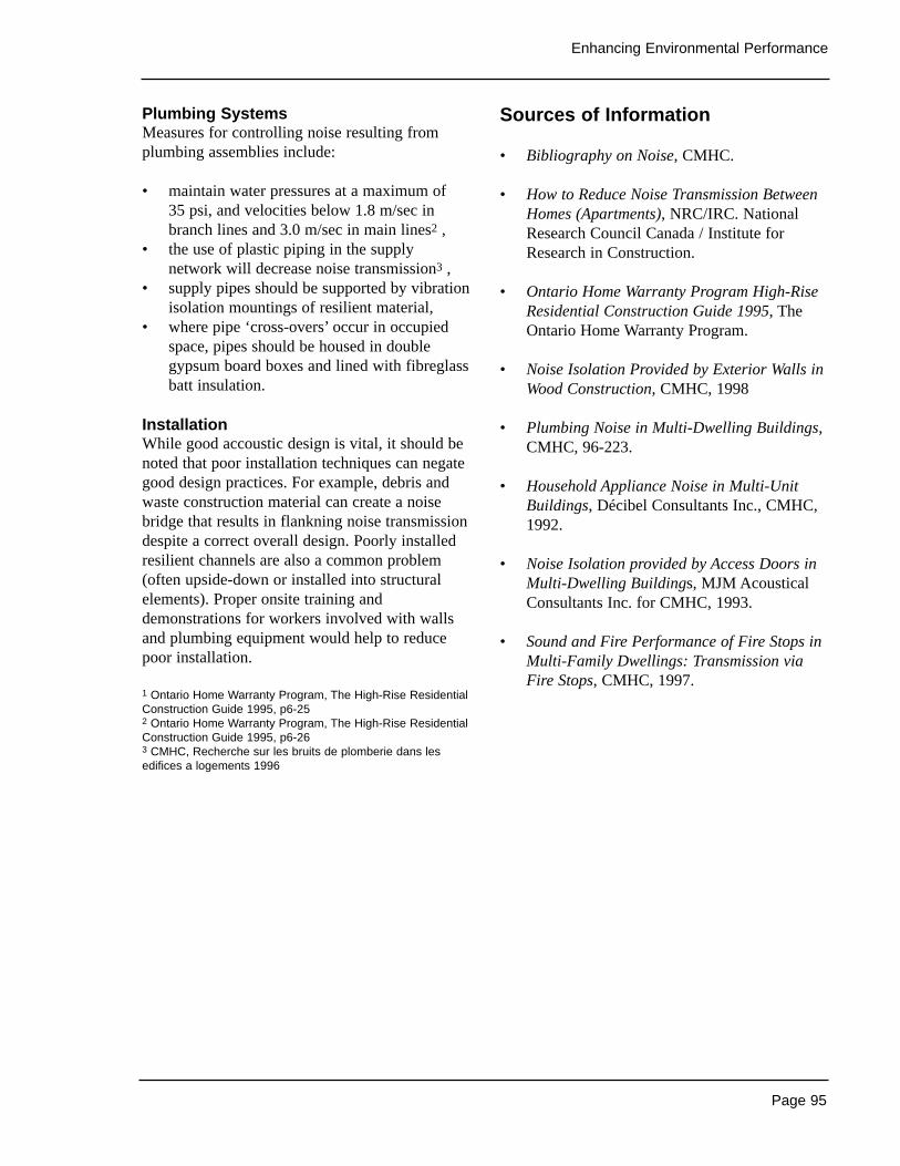
Page 95
Enhancing Environmental Performance
Plumbing SystemsMeasures for controlling noise resulting fromplumbing assemblies include:
• maintain water pressures at a maximum of 35 psi, and velocities below 1.8 m/sec inbranch lines and 3.0 m/sec in main lines2 ,
• the use of plastic piping in the supplynetwork will decrease noise transmission3 ,
• supply pipes should be supported by vibrationisolation mountings of resilient material,
• where pipe ‘cross-overs’ occur in occupiedspace, pipes should be housed in doublegypsum board boxes and lined with fibreglassbatt insulation.
InstallationWhile good accoustic design is vital, it should benoted that poor installation techniques can negategood design practices. For example, debris andwaste construction material can create a noisebridge that results in flankning noise transmissiondespite a correct overall design. Poorly installedresilient channels are also a common problem(often upside-down or installed into structuralelements). Proper onsite training anddemonstrations for workers involved with wallsand plumbing equipment would help to reducepoor installation.
1 Ontario Home Warranty Program, The High-Rise ResidentialConstruction Guide 1995, p6-252 Ontario Home Warranty Program, The High-Rise ResidentialConstruction Guide 1995, p6-263 CMHC, Recherche sur les bruits de plomberie dans lesedifices a logements 1996
Sources of Information
• Bibliography on Noise, CMHC.
• How to Reduce Noise Transmission BetweenHomes (Apartments), NRC/IRC. NationalResearch Council Canada / Institute forResearch in Construction.
• Ontario Home Warranty Program High-RiseResidential Construction Guide 1995, TheOntario Home Warranty Program.
• Noise Isolation Provided by Exterior Walls inWood Construction, CMHC, 1998
• Plumbing Noise in Multi-Dwelling Buildings,CMHC, 96-223.
• Household Appliance Noise in Multi-UnitBuildings, Décibel Consultants Inc., CMHC,1992.
• Noise Isolation provided by Access Doors inMulti-Dwelling Buildings, MJM AcousticalConsultants Inc. for CMHC, 1993.
• Sound and Fire Performance of Fire Stops inMulti-Family Dwellings: Transmission viaFire Stops, CMHC, 1997.
Page 96
Healthy High-Rise
Site PlanningThe basic design considerations and approachesfor the environmental performance of buildings interms of site planning are the same for all regionsacross Canada, and have been addressed in theSite Planning section. For example, while thespecific natural features of any given site willdiffer, the basic concept of designing buildingsthat work in concert with existing contours, streamflows, vegetation patterns, and so on does not.
A key issue that will vary by region is theorientation of the building to take account ofseasonally varying needs for light and heat. InCanada, while climate varies by regions, mostbuildings nonetheless have more significantwinter heating loads than they do summer coolingloads, and thus the general approaches to buildingorientation will be similar. The general rule-of-thumb of ensuring maximum access to sunlightfor passive and active solar strategies by orientingbuildings SSE to SSW 5% to 15% will berelevant to most buildings.
The variation of wind patterns by region shouldalso be considered in order to optimise possibilitiesfor natural ventilation. While rules-of-thumb existfor incorporating natural ventilation strategies intothe design of high-rise buildings, these tend to beimpacted by micro-climatic influences(surrounding buildings, local storm patterns, etc.)as much as by regional directional wind patterns.Consideration of building orientation in terms ofwind patterns should therefore be conducted at asite-specific level.
Materials SelectionHistorically, the materials used in the constructionof buildings were a direct reflection of the localclimate combined with the materials readilyavailable and appropriate for building. Moderntechnology and transportation systems havealtered this situation, and the selection ofmaterials is rarely a result of these regionally-based factors alone. Indeed, cost has emerged asone of the key influences on the choice of
materials to be used in the construction of abuilding. From the perspective of environmentalperformance, however, a return to the traditionalmethod of selecting building materials would be prudent.
While all of the issues identified in the MaterialsSelection section should always be consideredwhen specifying materials, the key issues toconsider from a regional point of view aredurability and embodied energy. In terms ofdurability, regional climate differences areimportant because they will impact on the long-term performance of the materials. For example,wind can cause mechanical erosion, and thus inregions (particularly coastlines) where heavywinds are frequent, tougher finishes will berequired. Another example is that of the impact of wetting-freezing regimes on porous masonry.Where such conditions prevail, it is important touse denser brick and cement if masonry is to beused. As well, rain can have a significant impacton materials due to the acidity it contains, leadingto the corrosion of aluminium and the rusting offerrous metals.
The second key issue to consider from a regionalpoint of view is that of embodied energy. Theenergy required to transport materials to aconstruction site contributes a significant amountto the total embodied energy contained in amaterial, and thus, using locally-producedmaterials can have a notable impact on reducingthe embodied energy of a building. From thisperspective, the selection of materials should bepredicated in large part on what is readilyavailable and appropriate that does not have to betransported over long distances. This applies alsoto the use of salvaged and / or recycled materials,which should be considered appropriate forinclusion only if they are available in the localregion. Transporting salvaged timber overthousands of miles would result in negligibleenvironmental benefits since the energy embodiedin transportation would negate the productionenergy saved.
REGIONAL DIFFERENCES
Page 97
Enhancing Environmental Performance
Solid WasteStrategies for improving the environmentalperformance of buildings in terms of solid wasteare on the whole not sensitive to regionalvariation, with the exception of the generation of yard waste. In regions with a more temperateclimate in the winter, such as the west coast, it islikely that greater amounts of organic waste willbe generated in the winter than in colder climateregions. This does not, however, alter the basicdesign considerations and approaches.
WaterRegional differences affect how water pricing isdetermined across Canada. In general, apartmentbuildings are metered accounts as opposed to flatrate accounts. Prices are determined by municipalauthorities as the amount required to cover thecosts of operations and maintenance of treatmentplants, pumping stations and water conveyancesystems. The graph at left shows differences formulti-family units for some Canadian cities.
Landscape PracticesRegional variations will greatly affect landscapepractices. Vegetation will vary according to planthardiness zones. Plant hardiness zones are definedprimarily by precipitation levels, the frost-freeperiod and growing degree-days (annual sum of
normal degree-days above 5° C). In general,coastal climates tend to have longer summers thaninterior regions and thus will use more outdoorwater and sustain longer maintenance periods.These areas may also experience less wateringrestrictions due to higher precipitation volumes,although this will depend on many other factors.These regions will benefit the most fromlandscape practices that consider frequent rainfalloccurrences. Conversely, the Prairie regions haveshorter summers and therefore less residentialoutdoor water use (per m2). These regions, withtemperate climates, will benefit from landscapepractices for summer shading and snowaccumulation in winter. Dry, arid parts of Canadamay experience more water restrictions due tolower water supply recharge in combination withhigher vegetation watering requirements. Theseareas will benefit the most from solar radiationinterception practices. Northern regions use theleast amount of outdoor water, due the leastnumber of growing degree-days in Canada. Theseregions benefit from appropriate landscapepractices that deal with snow accumulation andthe control of winter winds.
Multi-Family Residential Water Charges
($/m3)
City $/M3
Victoria, BC 02.92
St. John’s, NFLD 0.357
Saskatoon, SASK 0.388
Vancouver, BC 0395
Lethbridge, AB 0.448
Edmonton, AB 0.704
Winnipeg, MA• 0.777
Toronto, ONT 1.104
Yellowknife, NWT 3.14
Source: Env. Canada etc
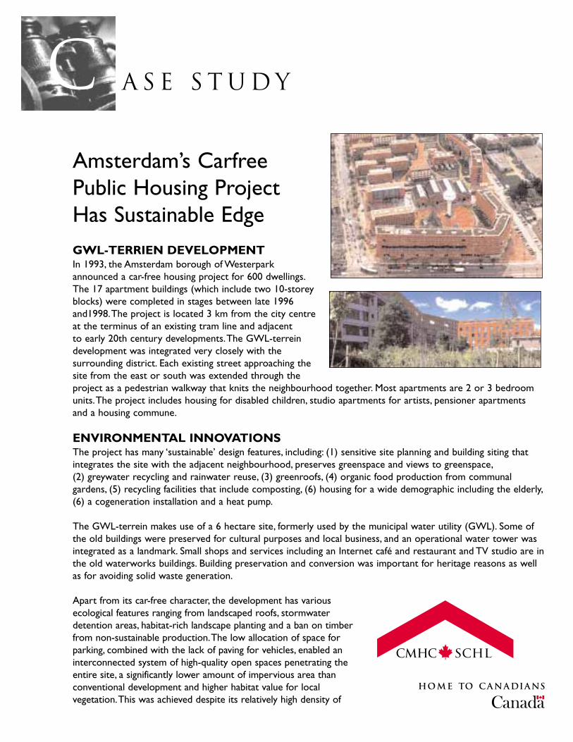
A S E S T U D YcAmsterdam’s Carfree Public Housing Project Has Sustainable EdgeGWL-TERRIEN DEVELOPMENTIn 1993, the Amsterdam borough of Westerparkannounced a car-free housing project for 600 dwellings.The 17 apartment buildings (which include two 10-storeyblocks) were completed in stages between late 1996and1998.The project is located 3 km from the city centreat the terminus of an existing tram line and adjacent to early 20th century developments.The GWL-terreindevelopment was integrated very closely with thesurrounding district. Each existing street approaching thesite from the east or south was extended through theproject as a pedestrian walkway that knits the neighbourhood together. Most apartments are 2 or 3 bedroomunits.The project includes housing for disabled children, studio apartments for artists, pensioner apartments and a housing commune.
ENVIRONMENTAL INNOVATIONSThe project has many ‘sustainable’ design features, including: (1) sensitive site planning and building siting thatintegrates the site with the adjacent neighbourhood, preserves greenspace and views to greenspace,(2) greywater recycling and rainwater reuse, (3) greenroofs, (4) organic food production from communalgardens, (5) recycling facilities that include composting, (6) housing for a wide demographic including the elderly,(6) a cogeneration installation and a heat pump.
The GWL-terrein makes use of a 6 hectare site, formerly used by the municipal water utility (GWL). Some ofthe old buildings were preserved for cultural purposes and local business, and an operational water tower wasintegrated as a landmark. Small shops and services including an Internet café and restaurant and TV studio are inthe old waterworks buildings. Building preservation and conversion was important for heritage reasons as wellas for avoiding solid waste generation.
Apart from its car-free character, the development has variousecological features ranging from landscaped roofs, stormwaterdetention areas, habitat-rich landscape planting and a ban on timberfrom non-sustainable production.The low allocation of space forparking, combined with the lack of paving for vehicles, enabled aninterconnected system of high-quality open spaces penetrating theentire site, a significantly lower amount of impervious area thanconventional development and higher habitat value for localvegetation.This was achieved despite its relatively high density of

150-200 persons per hectare. Recycling facilities are also available .Recycleables are separated into four categories (including organics) andcollected in underground containers at the perimeter of the site.
Water conservation is achieved via rainwater collection for toilet-flushingas well as some greywater recycling for non-potable use. Low-flow toiletshave also been installed.
Project Info
Location: Amsterdam, Netherlands
Architects: Kees Christiaanse Architects & PlannersDobbelaar de Kovel de Vroom ArchitectenAtelier Zienstra van der PolWJ Neutelings ArchitectuurMeyer en Van Schooten Architecten
Site Area: 6 hectares
Number of Dwellings: 600 units
Completion Date: 1998
Further Information: Opting for ChangeSustainable Building in the NetherlandsAeneas Technical PublishersPO Box 356,5680 AJ BESTThe Netherlandswww.aeneas.nl
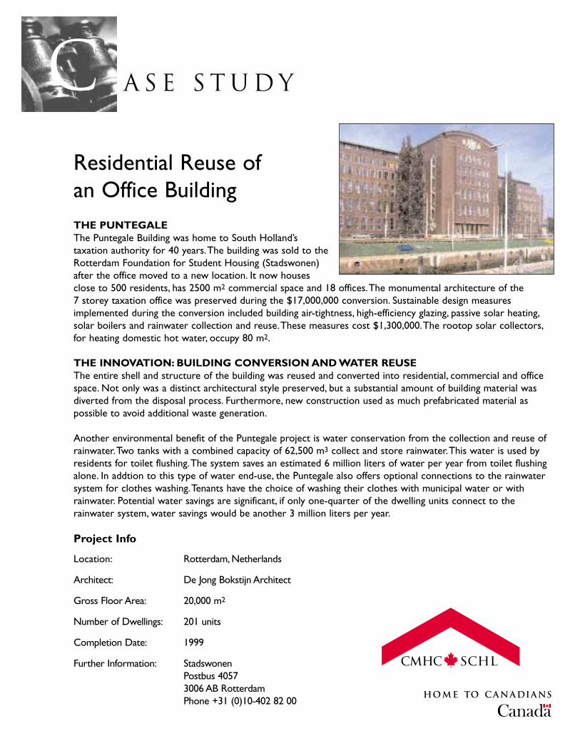
A S E S T U D YcResidential Reuse of an Office BuildingTHE PUNTEGALEThe Puntegale Building was home to South Holland’staxation authority for 40 years.The building was sold to theRotterdam Foundation for Student Housing (Stadswonen)after the office moved to a new location. It now housesclose to 500 residents, has 2500 m2 commercial space and 18 offices.The monumental architecture of the 7 storey taxation office was preserved during the $17,000,000 conversion. Sustainable design measuresimplemented during the conversion included building air-tightness, high-efficiency glazing, passive solar heating,solar boilers and rainwater collection and reuse.These measures cost $1,300,000.The rootop solar collectors,for heating domestic hot water, occupy 80 m2.
THE INNOVATION: BUILDING CONVERSION AND WATER REUSEThe entire shell and structure of the building was reused and converted into residential, commercial and officespace. Not only was a distinct architectural style preserved, but a substantial amount of building material wasdiverted from the disposal process. Furthermore, new construction used as much prefabricated material aspossible to avoid additional waste generation.
Another environmental benefit of the Puntegale project is water conservation from the collection and reuse ofrainwater.Two tanks with a combined capacity of 62,500 m3 collect and store rainwater.This water is used byresidents for toilet flushing.The system saves an estimated 6 million liters of water per year from toilet flushingalone. In addtion to this type of water end-use, the Puntegale also offers optional connections to the rainwatersystem for clothes washing.Tenants have the choice of washing their clothes with municipal water or withrainwater. Potential water savings are significant, if only one-quarter of the dwelling units connect to therainwater system, water savings would be another 3 million liters per year.
Project Info
Location: Rotterdam, Netherlands
Architect: De Jong Bokstijn Architect
Gross Floor Area: 20,000 m2
Number of Dwellings: 201 units
Completion Date: 1999
Further Information: StadswonenPostbus 40573006 AB RotterdamPhone +31 (0)10-402 82 00
Page 101
In This Section
Flexibility• site and circulation• dwelling unit layout• additional unit features
Case Studies
The aging of the population, home care for personswith disabilities, and the shift to ambulatorymedical care are trends that are now part of oureveryday life. In 1991, 15% of the Canadianpopulation had a mobility, agility, hearing, visionor speech impairment 1. In 1986, 21% of Canadianhouseholds had at least one person with adisability, and this percentage reached 40% amonghouseholds aged 65 years or older 2. The numberof seniors is expected to double between 1991 and2015, up to 7.2 million people.
As a result of these trends, consumer needs arechanging: residents are looking for well located,safer and better lit homes, as well as materialsthat are low-maintenance, equipment that is easyto manipulate, shorter travel routes to reducefatigue, etc. 3.
From a better building standpoint, thearchitectural design of buildings and housingunits, and the choice of materials and equipmentshould reflect these needs. This objective can beachieved with universal accessibility.
Through universal accessibility developers havethe opportunity to offer a distinctive product that will better meet the immediate needs ofconsumers, thereby gaining a significantcompetitive advantage.
Developers can also add a fast-growing clientgroup to their regular clientele: people concernedwith greater flexibility and better accessibility of their premises. Many residents are effectivelyaware that they will be able to stay in theiruniversally accessible dwellings if there needschange due to aging or a gradual or suddenappearance of temporary or permanentlimitations. It will also be easy for them toaccommodate friends or relatives with disabilities
Universal accessibility targets the entirepopulation. For developers, it provides a way tooffer added value and preserve permits buyers to preserve the value of their investment.
The recommended practices are simple. They areincorporated into the project right from the designstage. For the common areas of a building, theyare in line with existing regulations. For thedwellings, the idea is to provide unobstructedcirculation and strategically located manoeuvringareas. The choice of materials and equipmentenhances performance and safety.
The recommended practices generate little or noadditional expense, compared to conventionallydesigned units. It is advisable to incorporate theminto all the housing units in a project, in order toprovide the required flexibility at the time of saleor rental. These practices are to the advantage of everyone.
1 Health and Activity Limitation Survey, Statistics Canada,1986.2 A Socio-Demographic Profile of Canadians ExperiencingHealth or Activity Limitations, CMHC, 1991.3 Focus Groups to Examine Barrier-Free and AdaptableHousing Design, Hickling Corporation Inc. (1994).
ENHANCING ACCESSIBILITY
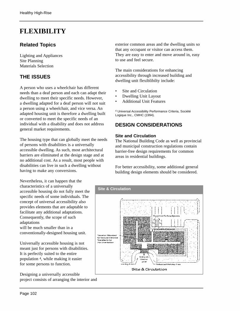
Page 102
Healthy High-Rise
Related Topics
Lighting and AppliancesSite PlanningMaterials Selection
THE ISSUES
A person who uses a wheelchair has differentneeds than a deaf person and each can adapt theirdwelling to meet their specific needs. However, a dwelling adapted for a deaf person will not suita person using a wheelchair, and vice versa. Anadapted housing unit is therefore a dwelling builtor converted to meet the specific needs of anindividual with a disability and does not addressgeneral market requirements.
The housing type that can globally meet the needsof persons with disabilities is a universallyaccessible dwelling. As such, most architecturalbarriers are eliminated at the design stage and atno additional cost. As a result, most people withdisabilities can live in such a dwelling withouthaving to make any conversions.
Nevertheless, it can happen that thecharacteristics of a universallyaccessible housing do not fully meet thespecific needs of some individuals. Theconcept of universal accessibility alsoprovides elements that are adaptable tofacilitate any additional adaptations.Consequently, the scope of suchadaptationswill be much smaller than in aconventionally-designed housing unit.
Universally accessible housing is notmeant just for persons with disabilities.It is perfectly suited to the entirepopulation 4, while making it easier for some persons to function.
Designing a universally accessibleproject consists of arranging the interior and
exterior common areas and the dwelling units sothat any occupant or visitor can access them.They are easy to enter and move around in, easyto use and feel secure.
The main considerations for enhancingaccessibility through increased building anddwelling unit flexiblibilty include:
• Site and Circulation• Dwelling Unit Layout• Additional Unit Features
4 Universal Accessibility Performance Criteria, SociétéLogique Inc., CMHC (1994).
DESIGN CONSIDERATIONS
Site and CirculationThe National Building Code as well as provincialand municipal construction regulations containbarrier-free design requirements for commonareas in residential buildings.
For better accessibility, some additional generalbuilding design elements should be considered.
FLEXIBILITY
Site & Circulation
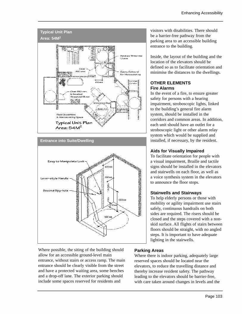
Page 103
Enhancing Accessibility
Where possible, the siting of the building shouldallow for an accessible ground-level mainentrance, without stairs or access ramp. The mainentrance should be clearly visible from the streetand have a protected waiting area, some benchesand a drop-off lane. The exterior parking shouldinclude some spaces reserved for residents and
visitors with disabilities. There shouldbe a barrier-free pathway from theparking area to an accessible buildingentrance to the building.
Inside, the layout of the building and thelocation of the elevators should bedefined so as to facilitate orientation andminimise the distances to the dwellings.
OTHER ELEMENTSFire AlarmsIn the event of a fire, to ensure greatersafety for persons with a hearingimpairment, stroboscopic lights, linkedto the building’s general fire alarmsystem, should be installed in thecorridors and common areas. In addition,each unit should have an outlet for astroboscopic light or other alarm relaysystem which would be supplied andinstalled, if necessary, by the resident.
Aids for Visually ImpairedTo facilitate orientation for people with a visual impairment, Braille and tactilesigns should be installed in the elevatorsand stairwells on each floor, as well as a voice synthesis system in the elevatorsto announce the floor stops.
Stairwells and StairwaysTo help elderly persons or those withmobility or agility impairment use stairssafely, continuous handrails on bothsides are required. The risers should beclosed and the steps covered with a non-skid surface. All flights of stairs betweenfloors should be straight, with no angledsteps. It is important to have adequatelighting in the stairwells.
Parking AreasWhere there is indoor parking, adequately largereserved spaces should be located near theelevators, to reduce the travelling distance andthereby increase resident safety. The pathwayleading to the elevators should be barrier-free,with care taken around changes in levels and the
Entrance into Suite/Dwelling
Typical Unit Plan
Area: 54M2
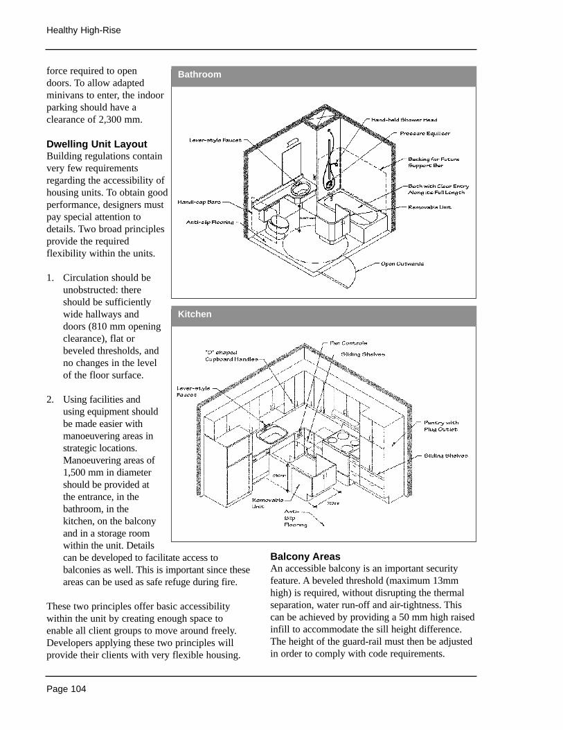
Page 104
Healthy High-Rise
force required to opendoors. To allow adaptedminivans to enter, the indoorparking should have aclearance of 2,300 mm.
Dwelling Unit LayoutBuilding regulations containvery few requirementsregarding the accessibility ofhousing units. To obtain goodperformance, designers mustpay special attention todetails. Two broad principlesprovide the requiredflexibility within the units.
1. Circulation should beunobstructed: thereshould be sufficientlywide hallways anddoors (810 mm openingclearance), flat orbeveled thresholds, andno changes in the levelof the floor surface.
2. Using facilities andusing equipment shouldbe made easier withmanoeuvering areas instrategic locations.Manoeuvering areas of1,500 mm in diametershould be provided atthe entrance, in thebathroom, in thekitchen, on the balconyand in a storage roomwithin the unit. Detailscan be developed to facilitate access tobalconies as well. This is important since theseareas can be used as safe refuge during fire.
These two principles offer basic accessibilitywithin the unit by creating enough space toenable all client groups to move around freely.Developers applying these two principles willprovide their clients with very flexible housing.
Balcony AreasAn accessible balcony is an important securityfeature. A beveled threshold (maximum 13mmhigh) is required, without disrupting the thermalseparation, water run-off and air-tightness. Thiscan be achieved by providing a 50 mm high raisedinfill to accommodate the sill height difference.The height of the guard-rail must then be adjustedin order to comply with code requirements.
Bathroom
Kitchen
Page 105
Enhancing Accessibility
Subsequent AdaptationsSome elements to facilitate subsequentadaptations can also be included:• for possible installation of grab bars, plywood
backing for nailing placed behind the tilearound the toilet and the bath enclosure,
• for possible installation of a wall oven, avertical kitchen cupboard with an appropriateelectrical outlet,
• for possible sink and washbasin kneeclearance, a removable cabinet module andoff-centre drainage plumbing,
• for lowering the clothes rods in the closets, a two-tiered clothes rod support.
The universal access concept does not usuallyrequire any additional space, in spite of the necessarymanoeuvring areas. In fact, by streamlining thearrangement of the spaces, it is possible to designuniversally accessible units with the same floor areaas conventional units. However, this will certainly beeasier to achieve in buildings with generous spacesthan in those where unit sizes are limited.
A range of good quality products exist on themarket that are efficient for accessibility, at prices comparable to conventional products. It istherefore possible to choose accessible productsand materials, at no additional cost.
Additional Unit FeaturesFor developers who wish to further improve theirhousing, some additional elements can beintegrated to facilitate use, such as:• lever faucets and door handles,• locks that can be easily handled with one hand,• a second peephole in the door at a maximum
height of 1,200 mm,• closet doors with an opening clearance of
810 mm,• switches, thermostats, electrical panel and
outlets located between 450 and 1,200 mmfrom the floor, and more than 300 mm fromwall corners,
• an electrical outlet near the bed, linked to aswitch near the door,
• range hood controls on the counter-front,• telephone–style shower,• pressure equalizers for bath and shower
fixtures,
• D-shaped cabinet and drawer handles,• sliding shelves in the cupboards,• non-skid, low-maintenance floor surfaces,• window sills at a maximum of 750 mm from
the floor,• an intercom linked to the telephone.
Sources of Information
• Adapting Low-rise Residential Buildings,Sun Ridge Group, CMHC, PE0292
• FlexHousing - Homes that Adapt to Life’sChanges, CMHC NHA #2020
• FlexHousing the Professionals’ Guide,CMHC NHA # 2400
• Design Options for Barrier-Free andAdaptable Housing, Société Logique Inc. et al., CMHC, 1996.
• Housing Choices for Canadians withDisabilities, CMHC, 1992.
• Universal Accessibility Performance Criteria,Société Logique Inc., CMHC, 1994.
• Building for a Lifetime: the Design andConstruction of Fully Accessible Homes,Wylde, Baron-Robbins, Clard, The TauntonPress, USA, 1994.
• Barrier-Free Design: A National Standard of Canada, CAN/CSA B-651-95, CanadianStandards Association, 1995.
• Housing for Persons with Disabilities,CMHC, 1996.
• Housing for Elderly People: DesignGuidelines, CMHC, 1987.
• Un logis bien pensé, j’y vis, j’y reste, Sociétéd’habitation du Québec, 1999.
• La domotique, Girardin P., Sociétéd’habitation du Québec, 1994.
• Les seuils d’accès facile aux balcons, PierreRichard,SCHL, 1999.
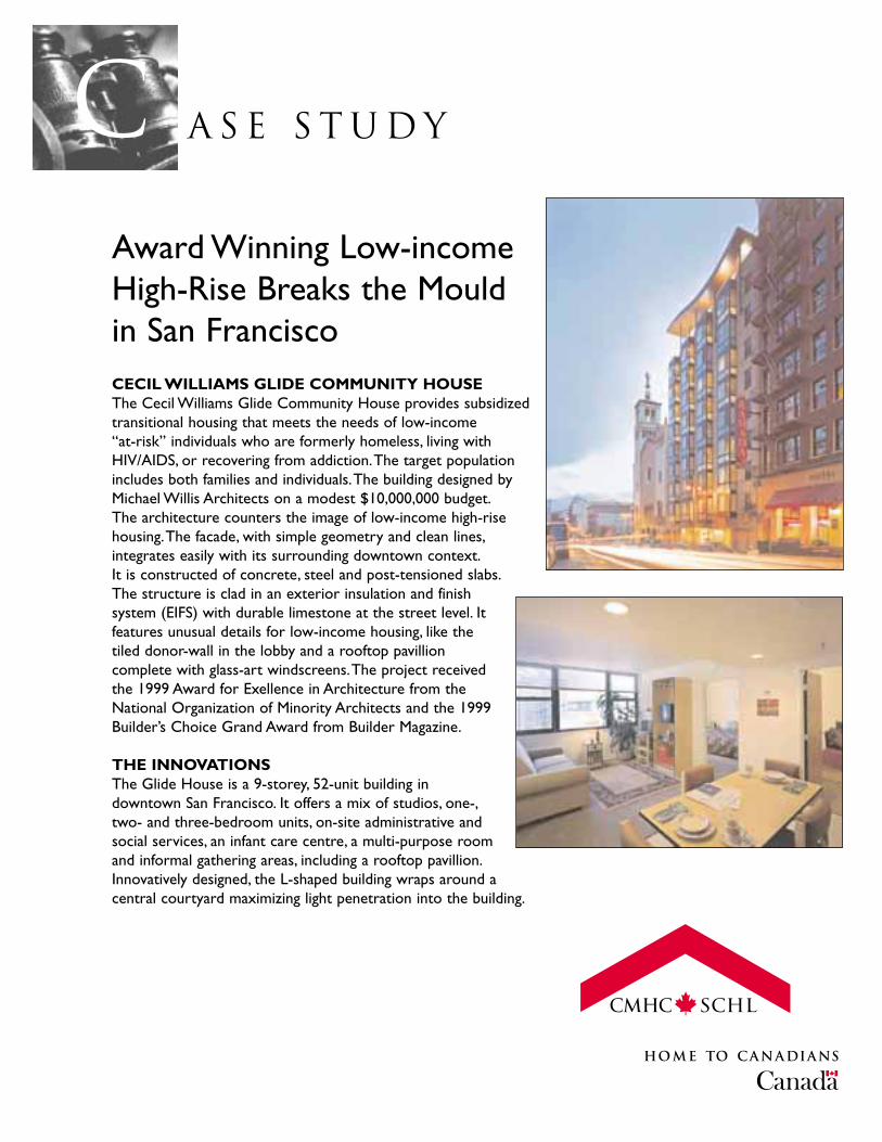
A S E S T U D YcAward Winning Low-incomeHigh-Rise Breaks the Mouldin San FranciscoCECIL WILLIAMS GLIDE COMMUNITY HOUSEThe Cecil Williams Glide Community House provides subsidizedtransitional housing that meets the needs of low-income “at-risk” individuals who are formerly homeless, living withHIV/AIDS, or recovering from addiction.The target populationincludes both families and individuals.The building designed byMichael Willis Architects on a modest $10,000,000 budget.The architecture counters the image of low-income high-risehousing.The facade, with simple geometry and clean lines,integrates easily with its surrounding downtown context.It is constructed of concrete, steel and post-tensioned slabs.The structure is clad in an exterior insulation and finishsystem (EIFS) with durable limestone at the street level. Itfeatures unusual details for low-income housing, like thetiled donor-wall in the lobby and a rooftop pavillioncomplete with glass-art windscreens.The project receivedthe 1999 Award for Exellence in Architecture from theNational Organization of Minority Architects and the 1999Builder’s Choice Grand Award from Builder Magazine.
THE INNOVATIONSThe Glide House is a 9-storey, 52-unit building indowntown San Francisco. It offers a mix of studios, one-,two- and three-bedroom units, on-site administrative andsocial services, an infant care centre, a multi-purpose roomand informal gathering areas, including a rooftop pavillion.Innovatively designed, the L-shaped building wraps around a central courtyard maximizing light penetration into the building.

The public areas in the building are fully-accessible to wheelchairs and 4 of the units are designed specifically for wheelchair occupants.Theother units have been built to be adaptable to accommodate wheelchairs.All the washrooms are wheelchair accessible. Other accessible designfeatures include lever-style door handles, low window sills, sliding cupboarddoors, front-accessible controls on stoves and clothes wahing/dryingmachines and fully accessible bathing fixtures (hinged pull-down seat, lever-style showerheads, grab bars, etc.).
Project Info
Location: San Fancisco, USA
Architect: Michael Willis,Architects
Gross Floor Area: 4700 M2
Number of Dwellings: 52 units
Completion Date: 1999
Further Information: Cecil Williams-GLIDE Community House333 Taylor St.San FranciscoUSA 94012Phone (415) 674-6100 http://www.glide.orghttp://www.mwarchitects.com

A S E S T U D YcBlair Court an Example of Sustainable, UniversalHousingBLAIR COURTBlair Court is a mixed-use residential/commercial building that was designed in 1990 as a home to seniors, people withdisabilities, single parent families and lower income groups.The project was sponsored by the Province of BritishColumbia and developed jointly by the Vancouver Resource Society (VRS) and a private landowner. In 1992, the CanadaMortgage and Housing Corporation awarded the project the CMHC Housing Award for Financing and Tenure.Aredesign of its courtyards and open spaces in 1998 improved the livability and accessibility of the original design.
While in the early 1970’s the choices open to people with disabilities in B.C. were limited to either living in aninstitutional setting, a group home or with a 24-hour attendant,VRS wanted to promote the integration andindependent lifestyles for those with disabilities.The Blair Court project sought to create a universally accessiblebuilding, using subtle design modifications, that would support a mix of residents, and encourage a neighbourlyatmosphere.
THE INNOVATIONSOf the 39 suites in Blair Court, approximately 20 are wheelchair accessible, 10 are wheelchair adaptable and theremaining 9 are of standard design.The building incorporated a number of barrier-free design features, includingwider door widths, levered door handles, and horizontal floor panels in the elevators.The suites are compact,efficient, and roomy in the areas needed to be so. By placing the commercial space at grade, and locating theresidential units on the upper floors, the designers also created a safe, secure, open courtyard oriented to thesouth that residents can access from their homes.
The courtyard’s landscape features were also designed with accessibility in mind. Planter heights and widths werereconfigured for wheelchair access (530 mm above pavers and 762 mm respectively), walls were given shelf-like cappingto permit the placement of potted plants, and hosebibs with more readily accessible lever handles were installed.
Project Info
Location: Vancouver, Canada
Architect: Neale Staniskis Doll Adams
Number of Dwellings: 39 units
Completion Date: 1990
Further Information: Vancouver Resource Society310-2150 West BroadwayVancouver, BCCanada V6K 4L9Phone (604) 731-1020
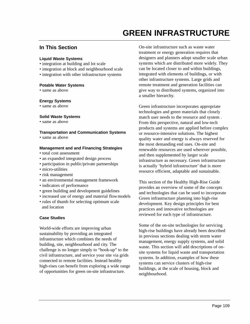
Page 109
In This Section
Liquid Waste Systems• integration at building and lot scale• integration at block and neighbourhood scale• integration with other infrastructure systems
Potable Water Systems• same as above
Energy Systems• same as above
Solid Waste Systems• same as above
Transportation and Communication Systems• same as above
Management and and Financing Strategies• total cost assessment• an expanded integrated design process• participation in public/private partnerships• micro-utilities• risk management• an environmental management framework• indicators of performance• green building and development guidelines• increased use of energy and material flowmodels• rules of thumb for selecting optimum scale
and location
Case Studies
World-wide efforts are improving urbansustainability by providing an integratedinfrastructure which combines the needs ofbuilding, site, neighbourhood and city. Thechallenge is no longer simply to “hook-up” to thecivil infrastructure, and service your site via gridsconnected to remote facilities. Instead healthyhigh-rises can benefit from exploring a wide rangeof opportunities for green on-site infrastructure.
On-site infrastructure such as waste watertreatment or energy generation requires thatdesigners and planners adopt smaller scale urbansystems which are distributed more widely. Theycan be located closer to and within buildings,integrated with elements of buildings, or withother infrastructure systems. Large grids andremote treatment and generation facilities cangive way to distributed systems, organized into a smaller hierarchy.
Green infrastructure incorporates appropriatetechnologies and green materials that closelymatch user needs to the resource and system .From this perspective, natural and low-techproducts and systems are applied before complexor resource-intensive solutions. The highestquality water and energy is always reserved forthe most demanding end uses. On-site andrenewable resources are used wherever possible,and then supplemented by larger scaleinfrastructure as necessary. Green infrastructure is actually ‘hybrid infrastructure’ that is moreresource efficient, adaptable and sustainable.
This section of the Healthy High-Rise Guideprovides an overview of some of the concepts and technologies that can be used to incorporateGreen infrastructure planning into high-risedevelopment. Key design principles for bestpractices and innovative technologies arereviewed for each type of infrastructure.
Some of the on-site technologies for servicinghigh-rise buildings have already been described in previous sections dealing with storm watermanagement, energy supply systems, and solidwaste. This section will add descriptions of on-site systems for liquid waste and transportationsystems. In addition, examples of how thesesystems can service clusters of high-risebuildings, at the scale of housing, block andneighbourhood.
GREEN INFRASTRUCTURE
Page 110
Healthy High-Rise
TRANSFORMING THE CITY
Green infrastructure revolutionizes the scope of design issues for buildings and and urbansystems. This change is analogous to thecomputer revolution, where a large, centralized,expensive and single purpose ‘main frame’infrastructure has been almost completelyreplaced by a diverse network of on-site systems.
At the block and neighbourhood scale, thedistribution nodes will include clustered, self-reliant, mixed developments of housing,commercial space and industry. Every largehousing development may be seen simultaneouslyan opportunity for a water factory, an electricalgenerating system, a solid waste managementsystem, a storm water management system, a communications node, an agricultural facility,an employment centre and so on.
As a consequence, the design process isbecoming more challenging and interdisciplinary.Increasingly we see a blurring of the traditionalboundaries that separate one type of ‘building’from another, and buildings from their civilinfrastructure. Large distribution grids and remotetreatment and generation facilities are giving wayto a network of ‘on-site’ infrastructure systems,with shared elements.
More mixed-use land use and building types cancomplement the on-site infrastructure systems, by evening-out the demand for services, andcreating opportunities for re-use and synergy. The traditional parceling of land with theisolation of industry and infrastructure will giveway to a multi-layered approach. We will literallywrap our homes and offices around the industrialand infrastructure systems, as they become ashared source of warmth, water, food and diverseemployment.
Such a transformation will be difficult given thecurrent norms for private property, and existingfee structures and planning policies for municipaland regional utilities. However on-site,sustainable integration becomes increasinglymore possible as utilities are deregulated and ascapital projects are delivered through publicprivate partnerships and performance-basedcontracts.
‘Micro’ utility servicing equipment is nowavailable for on-site water treatment, waterrecycling, cogeneration and heat transfer.Innovative storage systems can be used toenhance renewable energy supplies. Artificialintelligence can support more inexpensive safetysystems and can help to control flows ofresources between housing developments andgrids. New financial resources will be directed atprotecting the capacity of the local ecosystems,and reducing greenhouse gas emissions.
All these innovations are opening the door to amore flexible, diverse and integrated approach toproviding urban services for high-rise residentialbuildings.
Page 111
Green Infrastructure
THE ISSUESDevelopers and communities in Canada areadopting integrated, ecological approaches towastewater treatment and water reclamation. A motivation is the general public disdain forreliance upon chemical processes for wastewatertreatment. The success of many constructedwetlands is another driver. Public officials inCanada are starting to recognise the benefits ofecologically engineered systems which are widelyaccepted in Europe.
Green wastewater infrastructure is superior inremoving VOCs, hydrocarbons, nutrients,herbicides and pesticides, in addition topathogens. They don’t simply manage the waste,but instead transform the resource into reclaimedwater, soils, nutrients, CO2 and biodiversity. At a local scale, it means the re-integration of thewasted resource while minimising distributioncosts and land use.
DESIGN CONSIDERATIONS
Integration at Building and Lot Scale
Flow reduction at sourceThe first step is to reduce the flow of wastewaterleaving the building. Storm water is directed intoopen drainage systems. Water use indoors isminimised through use of water-conservingfixtures.
On-site compostingWaterless composting toilets can cope with allthat sewage. Ventilated aerobic compostingsystem reduce the waste volume by 90% andremoves pathogens. The humus-like soilamendment which results is rich in nitrogen andother useful elements. Returning it to the earthrestores depleted soil conditions. Fluid waste istreated in small odourless reed patches next tobuilding. Substantial amounts of water are savedrelative to conventional flush toilets.
On-site primary treatmentPrimary treatment is achievable at the buildingscale. Watertight concrete septic tanks next to thefoundations of apartment buildings can becomethe primary treatment stage for all wastewater.The advantage of having this system next to the building is that it then becomes possible toprovide very low cost, flexible and advancedsecondary treatment at the neighbourhood scale.Basically a submersible pump is used to decantthe fluid in each septic tank, and then send thefluid through small-diameter PVC pipes to aneighbourhood scale digester.
Integration at Block and NeighbourhoodScale
Advanced Secondary Treatment usingAggregate or Membrane Filtration
These systems can be dedicated to serve largemulti-unit residential buildings, or clusters, oreven small towns. Essentially a piped systemtransfers effluent from septic tanks to a centrallocation. A recirculation pump repeatedly spraysthe effluent over a subterranean gravel ormembrane filter, which drains back to the tank.After 2 or 3 days of periodic spraying, theanaerobic digestion is complete, and the effluent iscolourless and odourless (although still high innitrogen). This treated effluent is suitable for usein augmenting and flushing ponds and rivers, andfor use in irrigation, in non-potable water systems,and in industrial processes. The filter bed canoccupy a small area within the cluster ofbuildings, where it can serve as a multi-purposeoutdoor courtyard for passive recreation activities.
Solar Aquatic Sewage Treatment Systems Solar Aquatics is engineered technology thatreplicates the natural purifying processes of fresh water streams, meadows and wetlands.Wastewater flows through a series of clear-sidedtanks located in greenhouses, and then throughengineered streams and marshes wherecontaminants are metabolized or bound up.Bacteria, algae, plants and aquatic animals are
LIQUID WASTE SYSTEMS
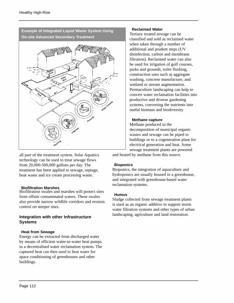
Page 112
Healthy High-Rise
all part of the treatment system. Solar Aquaticstechnology can be used to treat sewage flowsfrom 20,000-500,000 gallons per day. Thetreatment has been applied to sewage, septage,boat waste and ice cream processing waste.
Biofiltration MarshesBiofiltration swales and marshes will protect sitesfrom offsite contaminated waters. These swalesalso provide narrow wildlife corridors and erosioncontrol on steeper sites.
Integration with other InfrastructureSystems
Heat from SewageEnergy can be extracted from discharged water by means of efficient water-to-water heat pumpsin a decentralised water reclamation system. Thecaptured heat can then used to heat water forspace conditioning of greenhouses and otherbuildings.
Reclaimed WaterTertiary treated sewage can beclassified and sold as reclaimed waterwhen taken through a number ofadditional and prudent steps (UVdisinfection, carbon and membranefiltration). Reclaimed water can also be used for irrigation of golf courses,parks and grounds, toilet flushing,construction uses such as aggregatewashing, concrete manufacture, andwetland or stream augmentation.Permaculture landscaping can help toconvert water reclamation facilities intoproductive and diverse gardeningsystems, converting the nutrients intouseful biomass and biodiversity
Methane captureMethane produced in thedecomposition of municipal organicwastes and sewage can be piped tobuildings or to a cogeneration plant forelectrical generation and heat. Somesewage treatment plants are powered
and heated by methane from this source.
BioponicsBioponics, the integration of aquaculture andhydroponics are usually housed in a greenhouse,and integrated with greenhouse-based waterreclamation systems.
HumusSludge collected from sewage treatment plants is used as an organic additive to support stormwater filtration systems and other types of urbanlandscaping, agriculture and land restoration.
Example of Integrated Liquid Waste System Using
On-site Advanced Secondary Treatment
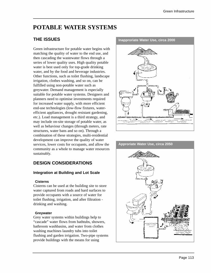
Page 113
Green Infrastructure
THE ISSUES
Green infrastructure for potable water begins withmatching the quality of water to the end use, andthen cascading the wastewater flows through aseries of lower quality uses. High quality potablewater is best used only for top-grade drinkingwater, and by the food and beverage industries.Other functions, such as toilet flushing, landscapeirrigation, clothes washing, and so on, can befulfilled using non-potable water such asgreywater. Demand management is especiallysuitable for potable water systems. Designers andplanners need to optimise investments requiredfor increased water supply, with more efficientend-use technologies (low-flow fixtures, water-efficient appliances, drought resistant gardening,etc.). Load management is a third strategy, andmay include on-site storage of potable water, aswell as behaviour changes (through meters, ratestructures, water bans and so on). Through acombination of these strategies, multi-residentialdevelopment can improve the quality of waterservices, lower costs for occupants, and allow thecommunity as a whole to manage water resourcessustainably.
DESIGN CONSIDERATIONS
Integration at Building and Lot Scale
CisternsCisterns can be used at the building site to storewater captured from roads and hard surfaces toprovide occupants with a source of water fortoilet flushing, irrigation, and after filtration -drinking and washing.
GreywaterGrey water systems within buildings help to“cascade” water flows from bathtubs, showers,bathroom washbasins, and water from clotheswashing machines laundry tubs into toiletflushing and garden irrigation. Two-pipe systemsprovide buildings with the means for using
Approriate Water Use, circa 2050
POTABLE WATER SYSTEMS
Inapproriate Water Use, circa 2000
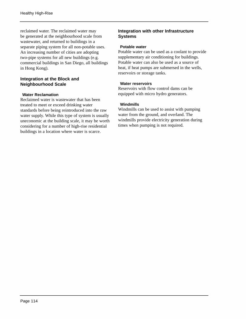
Page 114
Healthy High-Rise
reclaimed water. The reclaimed water may be generated at the neighbourhood scale fromwastewater, and returned to buildings in aseparate piping system for all non-potable uses.An increasing number of cities are adopting two-pipe systems for all new buildings (e.g.commercial buildings in San Diego, all buildingsin Hong Kong).
Integration at the Block andNeighbourhood Scale
Water ReclamationReclaimed water is wastewater that has beentreated to meet or exceed drinking waterstandards before being reintroduced into the rawwater supply. While this type of system is usuallyuneconomic at the building scale, it may be worthconsidering for a number of high-rise residentialbuildings in a location where water is scarce.
Integration with other InfrastructureSystems
Potable waterPotable water can be used as a coolant to providesupplementary air conditioning for buildings.Potable water can also be used as a source ofheat, if heat pumps are submersed in the wells,reservoirs or storage tanks.
Water reservoirsReservoirs with flow control dams can beequipped with micro hydro generators.
WindmillsWindmills can be used to assist with pumpingwater from the ground, and overland. Thewindmills provide electricity generation duringtimes when pumping is not required.
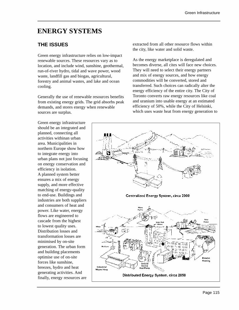
Page 115
Green Infrastructure
THE ISSUES
Green energy infrastructure relies on low-impactrenewable sources. These resources vary as tolocation, and include wind, sunshine, geothermal,run-of-river hydro, tidal and wave power, woodwaste, landfill gas and biogas, agricultural,forestry and animal wastes, and lake and oceancooling.
Generally the use of renewable resources benefitsfrom existing energy grids. The grid absorbs peakdemands, and stores energy when renewablesources are surplus.
Green energy infrastructureshould be an integrated andplanned, connecting allactivities withinan urbanarea. Municipalities innorthern Europe show howto integrate energy intourban plans not just focusingon energy conservation andefficiency in isolation. A planned system betterensures a mix of energysupply, and more effectivematching of energy-qualityto end-use. Buildings andindustries are both suppliersand consumers of heat andpower. Like water, energyflows are engineered tocascade from the highest to lowest quality uses.Distribution losses andtransformation losses areminimised by on-sitegeneration. The urban formand building placementsoptimise use of on-siteforces like sunshine,breezes, hydro and heatgenerating activities. Andfinally, energy resources are
extracted from all other resource flows within the city, like water and solid waste.
As the energy marketplace is deregulated andbecomes diverse, all cites will face new choices.They will need to select their energy partners and mix of energy sources, and how energycommodities will be converted, stored andtransferred. Such choices can radically alter theenergy efficiency of the entire city. The City ofToronto converts raw energy resources like coaland uranium into usable energy at an estimatedefficiency of 50%, while the City of Helsinki,which uses waste heat from energy generation to
ENERGY SYSTEMS
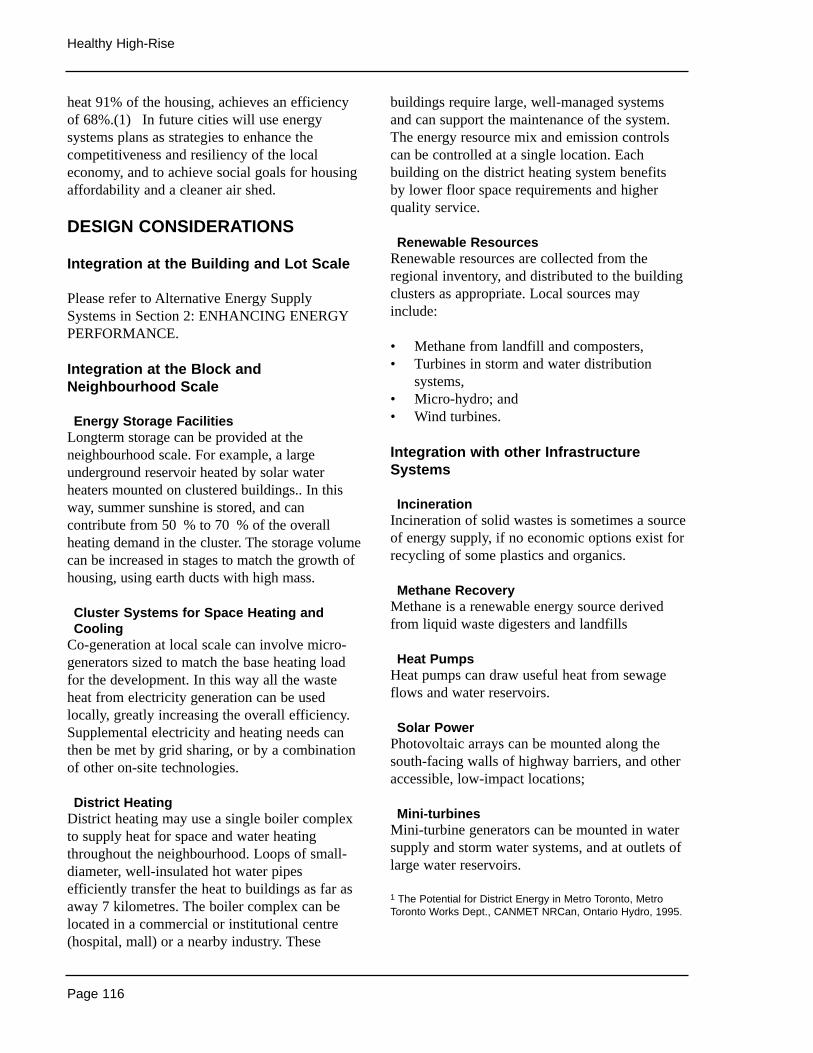
Page 116
Healthy High-Rise
heat 91% of the housing, achieves an efficiencyof 68%.(1) In future cities will use energysystems plans as strategies to enhance thecompetitiveness and resiliency of the localeconomy, and to achieve social goals for housingaffordability and a cleaner air shed.
DESIGN CONSIDERATIONS
Integration at the Building and Lot Scale
Please refer to Alternative Energy SupplySystems in Section 2: ENHANCING ENERGYPERFORMANCE.
Integration at the Block andNeighbourhood Scale
Energy Storage FacilitiesLongterm storage can be provided at theneighbourhood scale. For example, a largeunderground reservoir heated by solar waterheaters mounted on clustered buildings.. In thisway, summer sunshine is stored, and cancontribute from 50 % to 70 % of the overallheating demand in the cluster. The storage volumecan be increased in stages to match the growth ofhousing, using earth ducts with high mass.
Cluster Systems for Space Heating andCooling
Co-generation at local scale can involve micro-generators sized to match the base heating loadfor the development. In this way all the wasteheat from electricity generation can be usedlocally, greatly increasing the overall efficiency.Supplemental electricity and heating needs canthen be met by grid sharing, or by a combinationof other on-site technologies.
District HeatingDistrict heating may use a single boiler complexto supply heat for space and water heatingthroughout the neighbourhood. Loops of small-diameter, well-insulated hot water pipesefficiently transfer the heat to buildings as far asaway 7 kilometres. The boiler complex can belocated in a commercial or institutional centre(hospital, mall) or a nearby industry. These
buildings require large, well-managed systemsand can support the maintenance of the system.The energy resource mix and emission controlscan be controlled at a single location. Eachbuilding on the district heating system benefits by lower floor space requirements and higherquality service.
Renewable ResourcesRenewable resources are collected from theregional inventory, and distributed to the buildingclusters as appropriate. Local sources mayinclude:
• Methane from landfill and composters,• Turbines in storm and water distribution
systems,• Micro-hydro; and• Wind turbines.
Integration with other InfrastructureSystems
IncinerationIncineration of solid wastes is sometimes a sourceof energy supply, if no economic options exist forrecycling of some plastics and organics.
Methane RecoveryMethane is a renewable energy source derivedfrom liquid waste digesters and landfills
Heat PumpsHeat pumps can draw useful heat from sewageflows and water reservoirs.
Solar PowerPhotovoltaic arrays can be mounted along thesouth-facing walls of highway barriers, and otheraccessible, low-impact locations;
Mini-turbinesMini-turbine generators can be mounted in watersupply and storm water systems, and at outlets oflarge water reservoirs.
1 The Potential for District Energy in Metro Toronto, MetroToronto Works Dept., CANMET NRCan, Ontario Hydro, 1995.
Page 117
Green Infrastructure
THE ISSUES
Green infrastructure systems for solid wastemanage material resources, and eliminating wastealtogether. A green system thus requiresCoordination is required among those involved inthe material supply chain, to ensure that materialsare designed, packaged, transported, andassembled in a manner that minimises materialuse and that facilitates re-use and recycling. Toxicproducts are avoided, as are superfluous materialsfor decorative finishing. In ideal situations,manufacturers become service providers, anddirectly repossess the materials and goods when it is time to refit or recycle.
For high-rise developments, the solid wasteinfrastructure must be considered during the landclearing, construction and demolition stages, andon-going operating systems for the occupied site.
Land development must be consciously plannedto preserve existing vegetation wherever possible,and to compost the remaining organic materialson-site. Road and site excavation tries to equalizethe cut and fill. Building designs avoid wastefulpractices and incorporate materials that aredurable and easy to recycle. Construction anddemolition practices plan for waste management.
Once the site is occupied, organic materials mustbe kept nearby (instead of being trucked largedistances to landfills) and used to enrich thelandscape and to enhance the performance ofother infrastructure systems. The nodes forcollecting, separating, storing and re-using wastesneed to be carefully integrated into buildings,block and neighbourhood planning, so as toensure accessibility and social acceptability.
By following these broad waste managementstrategies, a high-rise development can become a key element in the urban waste managementinfrastructure.
DESIGN CONSIDERATIONS
Integration at Building and Lot Scale
Please refer to Solid Waste in Section 4.ENVIRONMENTAL PERFORMANCE.
Integration at Block and NeighbourhoodScale
Reuse It and Recycling DepotsLarger residential developments can benefit fromdepots for dropping off waste products. Suchdepots can often be integrated into the othercommunity facilities (school, day care,recreational park, corner store) and designed to enhance community interaction as residentsregularly deposit bottle returns, recyclingmaterials, and materials suitable for re-use.Depots can be combined with high-ratecomposting facilities as well.
CompostingComposting on a block or neighbourhood scaleuses a variety of systems:
• Windrows of organic waste typically requirea few acres of land. Raw organic materialssuch as yard trimmings are laid out in rowsand turned periodically. After they aredegraded by microbial activity the endproduct is relatively stable, reduced inquantity and free of offensive odours. Thehumus-like material can be recycled as a soil amendment and fertiliser substitute.
• Aerobic digesters use thermophilic (heatresponsive) microbes to process organicwaste over a 72-hour period with zeroharmful environmental discharge. Thedigested waste is converted into organicfertiliser products with high market value in both liquid and dry-pellet form.
• In-vessel composters are large containers thatprocess organic wastes over a two-weekperiod. A hopper at one end is used to loadthe vessel. An auger automatically mixes and
SOLID WASTE SYSTEMS

Page 118
Healthy High-Rise
turns the waste materials. A fan isused to ensure adequate suppliesof oxygen. Additional materialsmay the added to the vessel toensure that the mix of organics issuitable for efficient composting.The end product is humus thatcan be used in manufacturingsoils, and landscaping.
• Vermiculture systems use wormsto rapidly digest and sanitizeorganic wastes, including kitchenwaste and shredded cardboard.More hungry worms and highquality organic fertiliser areproduced.
• Enzyme-based compostingsystems are proprietary machinesthat accelerate the decompositionover several.
• Transfer and Sorting Stations:Neighbourhoods can accept smallstations that further separate thewaste and compact the materialbefore shipping to users. Localstations increase workopportunities and industrycustomers can locate close byfurther reducing transportationrequirements.
Integration with OtherInfrastructure Systems
Organic waste can be composted andincorporated as an absorptive soiladditive in an open storm watermanagement system.
Local, renewable energy can includethe methane generated fromcomposting solid wastes, and fromincineration.
Organic waste materials can also be top dressedon landscaped areas, and used to minimiseirrigation water supply requirements.
Solid waste management depots in theneighbourhood can also be used to reducerequirements for roads and to support lifestylesthat include neighbourhood shopping and walking.
Remote & Isolated Solid Waste Management, circa 2000
Clustered Solid Waste Management, circa 2050
Page 119
Green Infrastructure
THE ISSUES
Transportation as a service needs to be redefined.The object is accessibility, not moving people.Hence the green infrastructure for transportationmay actually consist of land use planning thatlocates jobs close to or inside housing, and thatensures clusters of services like shops, schoolsand parks are within walkable distances frommost residences. The cluster structure is a keydesign element. The connections between clustersof varying scales should also provide resource-efficient transport, include safe, dependable andconvenient transit, high quality amenities for non-vehicular transport (bicycles and walking) andamenities for non-fuel powered vehicles.Connections include communicationstechnologies that provide access without actuallymoving people and materials.
Electricity generated from renewable resources is especially well suited for light rail systems andtrolleys. Longer distances between major nodesare best suited for mass transit. European citiesshow how to lure people out of their singleoccupancy vehicles when dense mixed-useneighbourhoods are combined with extremelyclean, convenient and affordable transit. Bydiscouraging the use of private vehicles insidecities, areas covered by large road surfaces canbecome amenities that improve the quality andscope of living within cities. . Reduced smog isanother major contribution.
DESIGN CONSIDERATIONS
Integration at Building and Lot Scale
Complementary Building OccupanciesLocating several complementary occupancieswithin a project often eliminates the need formany automobile trips., Occupants can walk oruse lower-impact biking and transit. Parkingspaces in mixed-use buildings and developmentscan often be shared between occupancies withdiffering schedules, reducing the area of
impervious parking pavement, stormwater peakflows and pollution.
Pedestrian and Bicycle AmenitiesMaking streets safer and more attractive topedestrians will reduce car use. Bicycle facilitiesat destinations and safe, continuous bicycle pathsare also needed. Building designs can providesecure bicycle parking, showers and changingfacilities. Building designs can also improve the comfort and safety of pedestrians withappropriately scaled and detailed facades, andwith street views for building occupants.Provided with a choice of sun or shade,pedestrians are more likely to use outdoor spaces.An attractive street generates places for socialinteraction, increasing the vitality of theneighbourhood and providing better commercialopportunities.
Live-work spacesBuilding designs can include swing spaces thatcan be easily converted into home offices withsoundproof walls, direct access to exterior, andsuitable wiring, cable connections and lighting.Live-work spaces provide options both for tele-workers and the self-employed.
Transit AccessDesign details make a difference in comfort,convenience and accessibility to transit users. A clear line of sight to transit stops is ideal, withpaths that avoid crossing traffic, and with weatherprotected shelters .
Integration at Block and NeighbourhoodScale
Network of PathwaysPedestrian and bicycle paths encourage analternative to satisfy basic needs. Paths shouldconnect residential areas to amenities as well asto neighbouring communities. A fine-grainednetwork will include local connections withinblocks that in turn connect with a neghbourhoodsystem as well as the larger citywide network.
TRANSPORTATION & COMMUNICATION SYSTEMS
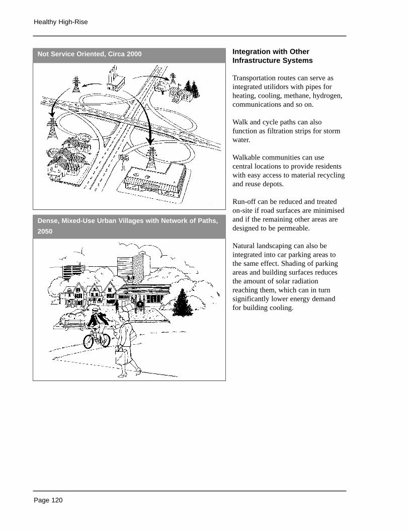
Page 120
Healthy High-Rise
Integration with OtherInfrastructure Systems
Transportation routes can serve asintegrated utilidors with pipes forheating, cooling, methane, hydrogen,communications and so on.
Walk and cycle paths can alsofunction as filtration strips for stormwater.
Walkable communities can usecentral locations to provide residentswith easy access to material recyclingand reuse depots.
Run-off can be reduced and treatedon-site if road surfaces are minimisedand if the remaining other areas aredesigned to be permeable.
Natural landscaping can also beintegrated into car parking areas tothe same effect. Shading of parkingareas and building surfaces reducesthe amount of solar radiationreaching them, which can in turnsignificantly lower energy demandfor building cooling.
Not Service Oriented, Circa 2000
Dense, Mixed-Use Urban Villages with Network of Paths,
2050
Page 121
Green Infrastructure
THE ISSUES
Integrated multi-functional infrastructure projectsare by their nature a difficult sell. Many of thebenefits are indirect, the risks appear to besubstantial, and the number of stakeholders canbe overwhelming. Extremely challengingobstacles must be addressed in order to minimisethe costs of on-site systems and to receive bothco-operation and compensation from localgovernments and utilities. Some of the morecommon obstacles include:
Formula ThinkingSystem designers have been trained to use slice-and-dice, component-based design methods thatare simple, clear, and wrong, because theyoptimise components in isolation and neglect the systems of which they are a part. They focuson single rather than multiple benefits.
Fragmentation of AuthorityHistorically, the development of each type ofinfrastructure occurred at different times, largelyin isolation. This has left us with agencies,industries, and monopolies organised aroundspecialised mandates, and withcompartmentalised worldviews.
Fragmentation of EcologiesIt is especially hard to protect and enhance theecological integrity of an area if other decision-makers erode the benefits. For example, reducingpollution on your site can be pointless if anotherdevelopment, upstream then chooses to pollutethe air or water at much higher levels.
Sunk InvestmentsThe very substantial capital outlays dedicated toexisting infrastructure can eliminate the potentialfor cost savings from green infrastructure.Sometimes property taxes are already predicatedon paying for larger, centralized systems, and thusanyone who invests more money to reducereliance upon such systems, ends up paying twice.
Inflexible PoliciesMany types of existing policies prevent holisticthinking and on-site applications. They often onlyrecognise one way of achieving results (the statusquo) and thus frustrate innovation within themarket place. Health and safety policies may notreflect new ecological technologies, and therelative importance of protecting environment.Land use policies may run completely counter tothe concept of mixed use and municipal ecology.
Bundled FeesSubsidies and fees are often structured in waysthat are insensitive to variations in user loads andconsumption rates. For example, developmentcost charges may be based entirely upon factorslike zoning and floor area, despite the possibilitythat the design of greener buildings and on-siteinfrastructure may reduce or even eliminate therequirement for certain types of municipalinfrastructure investments.
Larger Utilities Supporting Status QuoDespite efforts at deregulation, it is still possiblefor large utilities to influence the market, and tounder-price new initiatives that threaten theirmarket base.
Lack of comprehensive cost/benefit modelsCost benefit modelling of infrastructure optionscannot currently account for the potential benefitsof integrated systems, since the models are notbroad enough.
DESIGN CONSIDERATIONS
The many obstacles to green infrastructureemphasise the importance of adopting methodsand tools that contribute to successful projectmanagement. Some especially useful strategiesare outlined below.
Total Cost AssessmentGreen infrastructure is a non-starter as long asdevelopers apply conventional accounting
MANAGEMENT AND FINANCING
Page 122
Healthy High-Rise
practices, that separate budgets into ‘silos’, andthat reward false economies. An engineeringstudy may indicate that the lowest cost option isto ‘hook-up’ to the hydro grid and ignore on-siteenergy. However from a ‘total cost’ perspectivethe savings may be false, since a micro-generator,operated by a micro-utility, could provide bothheat and power, save the space and costs forindividual heating plants in each building, offerthe developer an on-going revenue stream, andoffer the residents security against rising energyprices and grid failures. Typical ‘cost/benefit’analysis usually fails to recognise the potential forgreen infrastructure. The solution is Total CostAssessment (TCA), which expands the financialanalysis to include a broader range of direct,indirect, contingent and less quantifiable costs.
TCA can be used to optimise the ‘looping’ offinancial resources, - reallocating cost savingsfrom one type of budget to another in order tofinance the lower-cost integrated system. Anexample might be the evaluation of designs for a denser, mixed-use community. TCA indicatesthat residents in the denser community will makefewer car trips, and require smaller roads andfewer parking spaces; thus money and land canbe taken from the transportation infrastructurebudget and used instead to pay for amenities likeparks and daycares in the denser, mixed-usedevelopment. Still more money can be taken fromhighway construction and upkeep budget, andused instead to subsidise live/workaccommodation or to provide communicationsystems for co-ordinating tele-workers andtransit. In a highly integrated development, it isnecessary to create a “megafund” forredistributing money across all classes ofinfrastructure interventions.
Expanded Integrated Design ProcessThe best method for addressing opportunities forgreen infrastructure is to expand the IntegratedDesign Process (IDP). Right from the start it isuseful to include on the team individualsknowledgeable about the opportunities andconstraints of the urban infrastructure.Unfortunately the tendency in most projects is tofocus initially on built form and land uses like open
space and transportation routes. An assumption ismade that infrastructure issues can be dealt with“later”, once the basic concept plans are completedand approved. However the reality is many greeninfrastructure solutions are intimately related toland use and built form. Thus it is vital to considerthe residential development and associated on-siteinfrastructure simultaneously, as part of anIntegrated Design Process.
Participation in Public PrivatePartnershipsMunicipal participation, in the form of publicprivate partnerships (PPPs), can be an essentialenabling strategy for the creation of moreintegrated and smaller scale infrastructure. Whilethe municipalities’ role in such partnerships mayremain small, their involvement will commonlyadd a large measure of confidence to the projectinvestors, and to the marketplace. With a lowerperceived risk among the stakeholders, itbecomes easier to find affordable financing.
Micro-utilitiesNeighbourhood scale integration raises substantialdifficulties in terms of ownership, liability andmaintenance of infrastructure systems. Often thisis the greatest obstacle to embracing greeninfrastructure. One solution is to facilitate thecreation of small, community-based utilities thatare capable of managing all aspects of sharedinfrastructure for the cluster. Everyone connectedto a system is automatically a stakeholder havingrevenue incentives to use the system responsibly.Success of resource recovery approaches mayrequire some guarantee of buyers for theproducts. Stakeholders have a built-in incentive toconsume the products (trees, water, beddingplants, flowers, tropical plants, compost,materials,) from their “own” utility therebysupporting its revenues and their dividends.and emissions associated with development plans.Essentially such a model will simulate theinteraction between buildings and other elementsof the city (infrastructure, people, ecologies) andaggregate the net impacts on resource use, costsand emissions. Impacts can be expressed usingstandard indicators of performance. The modelmust account for the dynamic relationships

Page 123
Green Infrastructure
between sectors, between resources, and betweensupply and demand systems, thus allowingdevelopers to accurately estimate and apportionthe full costs and benefits associated with Greeninfrastructure options.
Risk ManagementCivil engineering is a discipline that is by naturerisk averse. However a number of strategies maybe used to manage change and facilitate theacceptance of unfamiliar green infrastructuretechnologies The first strategy is to reduce theperceived risk by means of three tools:
Pilot tests: Significant changes are bestintroduced in stages, so that results can becarefully evaluated before widespread adoption.Pilot projects are often the most effective learningtools, and are particularly well suited to greeninfrastructure. They can happen at a small scalequickly and can take advantage of the redundancyprovided by larger existing systems
Contingency plans: The plans must clearly outlinethe approach to resolving failures, and mayactually layer green infrastructure on top oftraditional infrastructure for this purpose.
Precedents: Past experience with the sametechnology can be well documented, and verifiesthat what is planned has been proven to workwell in another location.
A second strategy is to find better ways of sharingrisks. Sometimes the risk is disproportionatelyborne by the developers and professionaldesigners, or by the city engineers and plannersthat approve and permit the new projects. Thesepeople may be risking their careers and reputationbecause they appear not to be using conventional“professional standards of good practice”. Sinceinnovation and experimentation is necessary andultimately beneficial to the entire community, theirrisk needs to be underwritten by the community. A revolving performance bond is one example ofhow this risk can be shared. Essentially a fund iscreated by all the stakeholders to “guarantee”performance of projects that appear to reflect thebest application of green infrastructure principles.
Environmental Management FrameworkA comprehensive Environmental ManagementFramework is another vital tool for steering aneffective public process and brokering greeninfrastructure solutions. Frameworks create amental map for setting and justifying specificenvironmental recommendations. They becomethe underlying structure through which urbandevelopers can transcend motherhood statementsand provide tangible, measurable targets fordesigning, assessing and marketing theperformance of a neighbourhood or project.Frameworks have recently achieved considerablesuccess in helping diverse groups reach consensusand create bold visions.
A typical framework can be represented as apyramid that has, at its top, a definition ofsustainable urban development, the fundamentalprinciples of eco-city planning, and the creation ofa unique “vision’ for the community. From thispinnacle, the Framework divides into a spreadingtree of elements, at increasing levels of specificity:
Principles are broad motherhood type statementsthat are intended to set the direction for all activitiesand to define the priorities. Stewardship of thenatural environment is an example of a principle
Goals elaborate upon the fundamental principlesand define the ultimate condition desired. Eachprinciple can have a number of goals associatedwith it. They indicate the direction of change thatis desired. Maintain and enhance the ecologicalfunction of the site is an example of a goal.
Key strategies identify basic approaches that canbe implemented in order to achieve the goals.Goals can be linked to a number of different keystrategies. Generally strategies should be selectedthat are known to address more than one goal.This is a comprehensive approach which canachieve synergies. Preserve natural drainagepatterns on all sites is an example of a keystrategy.
Specific Actions provide a range of activities thatcan be implemented in order to fulfil the keystrategies. By virtue of the clear link of key
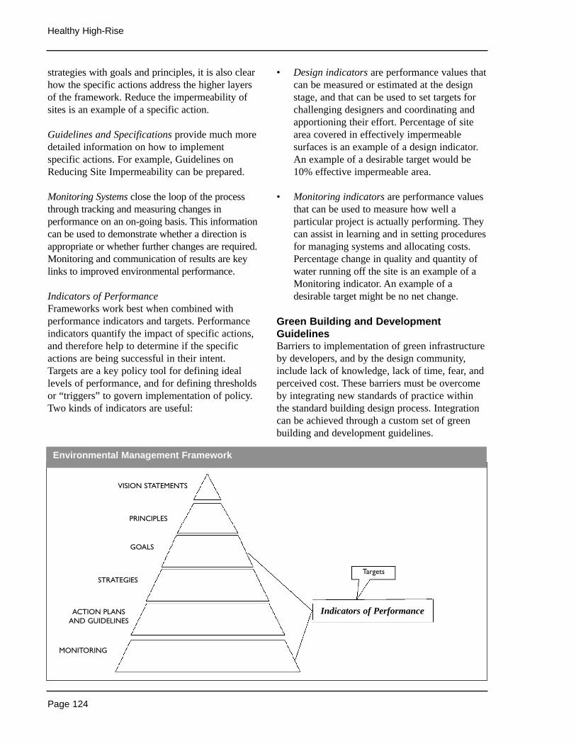
Page 124
Healthy High-Rise
strategies with goals and principles, it is also clearhow the specific actions address the higher layersof the framework. Reduce the impermeability ofsites is an example of a specific action.
Guidelines and Specifications provide much moredetailed information on how to implementspecific actions. For example, Guidelines onReducing Site Impermeability can be prepared.
Monitoring Systems close the loop of the processthrough tracking and measuring changes inperformance on an on-going basis. This informationcan be used to demonstrate whether a direction isappropriate or whether further changes are required.Monitoring and communication of results are keylinks to improved environmental performance.
Indicators of PerformanceFrameworks work best when combined withperformance indicators and targets. Performanceindicators quantify the impact of specific actions,and therefore help to determine if the specificactions are being successful in their intent.Targets are a key policy tool for defining ideallevels of performance, and for defining thresholdsor “triggers” to govern implementation of policy.Two kinds of indicators are useful:
• Design indicators are performance values thatcan be measured or estimated at the designstage, and that can be used to set targets forchallenging designers and coordinating andapportioning their effort. Percentage of sitearea covered in effectively impermeablesurfaces is an example of a design indicator.An example of a desirable target would be10% effective impermeable area.
• Monitoring indicators are performance valuesthat can be used to measure how well aparticular project is actually performing. Theycan assist in learning and in setting proceduresfor managing systems and allocating costs.Percentage change in quality and quantity ofwater running off the site is an example of aMonitoring indicator. An example of adesirable target might be no net change.
Green Building and DevelopmentGuidelinesBarriers to implementation of green infrastructureby developers, and by the design community,include lack of knowledge, lack of time, fear, andperceived cost. These barriers must be overcomeby integrating new standards of practice withinthe standard building design process. Integrationcan be achieved through a custom set of greenbuilding and development guidelines.
Environmental Management Framework
VISION STATEMENTS
PRINCIPLES
GOALS
STRATEGIES
ACTION PLANSAND GUIDELINES
MONITORING
Targets
Indicators of Performance
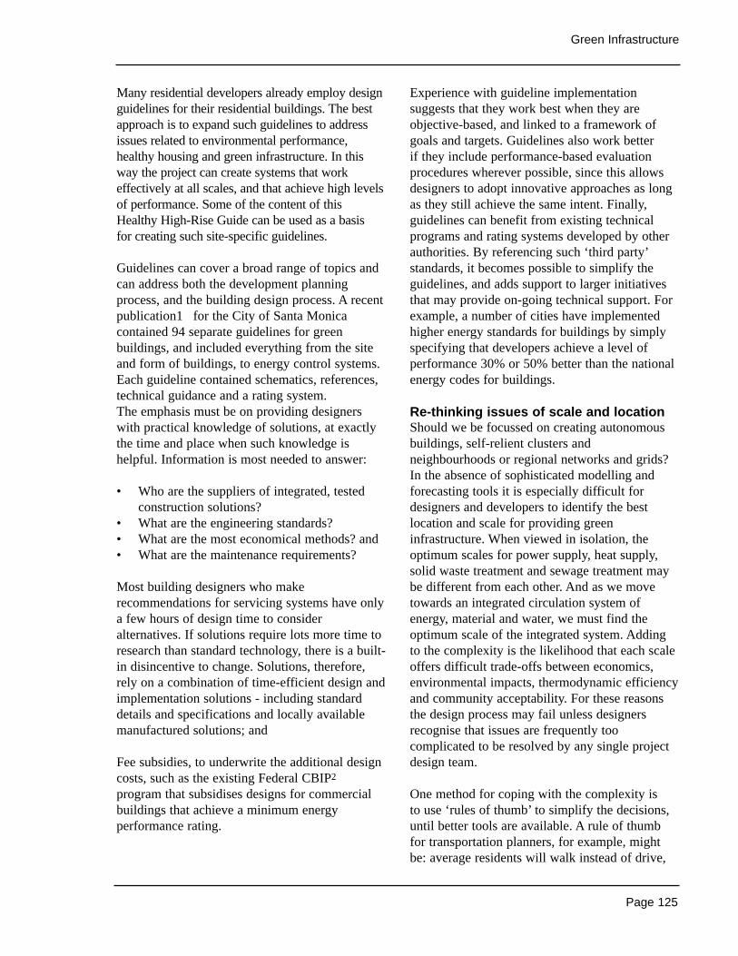
Page 125
Green Infrastructure
Many residential developers already employ designguidelines for their residential buildings. The bestapproach is to expand such guidelines to addressissues related to environmental performance,healthy housing and green infrastructure. In thisway the project can create systems that workeffectively at all scales, and that achieve high levelsof performance. Some of the content of thisHealthy High-Rise Guide can be used as a basis for creating such site-specific guidelines.
Guidelines can cover a broad range of topics andcan address both the development planningprocess, and the building design process. A recentpublication1 for the City of Santa Monicacontained 94 separate guidelines for greenbuildings, and included everything from the siteand form of buildings, to energy control systems.Each guideline contained schematics, references,technical guidance and a rating system. The emphasis must be on providing designerswith practical knowledge of solutions, at exactlythe time and place when such knowledge ishelpful. Information is most needed to answer:
• Who are the suppliers of integrated, testedconstruction solutions?
• What are the engineering standards? • What are the most economical methods? and • What are the maintenance requirements?
Most building designers who makerecommendations for servicing systems have onlya few hours of design time to consideralternatives. If solutions require lots more time toresearch than standard technology, there is a built-in disincentive to change. Solutions, therefore,rely on a combination of time-efficient design andimplementation solutions - including standarddetails and specifications and locally availablemanufactured solutions; and
Fee subsidies, to underwrite the additional designcosts, such as the existing Federal CBIP2
program that subsidises designs for commercialbuildings that achieve a minimum energyperformance rating.
Experience with guideline implementationsuggests that they work best when they areobjective-based, and linked to a framework ofgoals and targets. Guidelines also work better if they include performance-based evaluationprocedures wherever possible, since this allowsdesigners to adopt innovative approaches as longas they still achieve the same intent. Finally,guidelines can benefit from existing technicalprograms and rating systems developed by otherauthorities. By referencing such ‘third party’standards, it becomes possible to simplify theguidelines, and adds support to larger initiativesthat may provide on-going technical support. Forexample, a number of cities have implementedhigher energy standards for buildings by simplyspecifying that developers achieve a level ofperformance 30% or 50% better than the nationalenergy codes for buildings.
Re-thinking issues of scale and locationShould we be focussed on creating autonomousbuildings, self-relient clusters andneighbourhoods or regional networks and grids?In the absence of sophisticated modelling andforecasting tools it is especially difficult fordesigners and developers to identify the bestlocation and scale for providing greeninfrastructure. When viewed in isolation, theoptimum scales for power supply, heat supply,solid waste treatment and sewage treatment maybe different from each other. And as we movetowards an integrated circulation system ofenergy, material and water, we must find theoptimum scale of the integrated system. Addingto the complexity is the likelihood that each scaleoffers difficult trade-offs between economics,environmental impacts, thermodynamic efficiencyand community acceptability. For these reasonsthe design process may fail unless designersrecognise that issues are frequently toocomplicated to be resolved by any single projectdesign team.
One method for coping with the complexity is to use ‘rules of thumb’ to simplify the decisions,until better tools are available. A rule of thumbfor transportation planners, for example, mightbe: average residents will walk instead of drive,
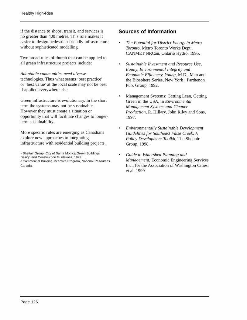
Page 126
Healthy High-Rise
if the distance to shops, transit, and services is no greater than 400 metres. This rule makes iteasier to design pedestrian-friendly infrastructure,without sophisticated modelling.
Two broad rules of thumb that can be applied toall green infrastructure projects include:
Adaptable communities need diversetechnologies. Thus what seems ‘best practice’or ‘best value’ at the local scale may not be bestif applied everywhere else.
Green infrastructure is evolutionary. In the shortterm the systems may not be sustainable.However they must create a situation oropportunity that will facilitate changes to longer-term sustainability.
More specific rules are emerging as Canadiansexplore new approaches to integratinginfrastructure with residential building projects.
1 Sheltair Group, City of Santa Monica Green BuildingsDesign and Construction Guidelines, 1999.2 Commercial Building Incentive Program, National ResourcesCanada.
Sources of Information
• The Potential for District Energy in MetroToronto, Metro Toronto Works Dept.,CANMET NRCan, Ontario Hydro, 1995.
• Sustainable Investment and Resource Use,Equity, Environmental Integrity andEconomic Efficiency, Young, M.D., Man andthe Biosphere Series, New York : ParthenonPub. Group, 1992.
• Management Systems: Getting Lean, GettingGreen in the USA, in EnvironmentalManagement Systems and CleanerProduction, R. Hillary, John Riley and Sons,1997.
• Enivironmentally Sustainable DevelopmentGuidelines for Southeast False Creek, APolicy Development Toolkit, The SheltairGroup, 1998.
• Guide to Watershed Planning andManagement, Economic Engineering ServicesInc., for the Association of Washington Cities,et al, 1999.
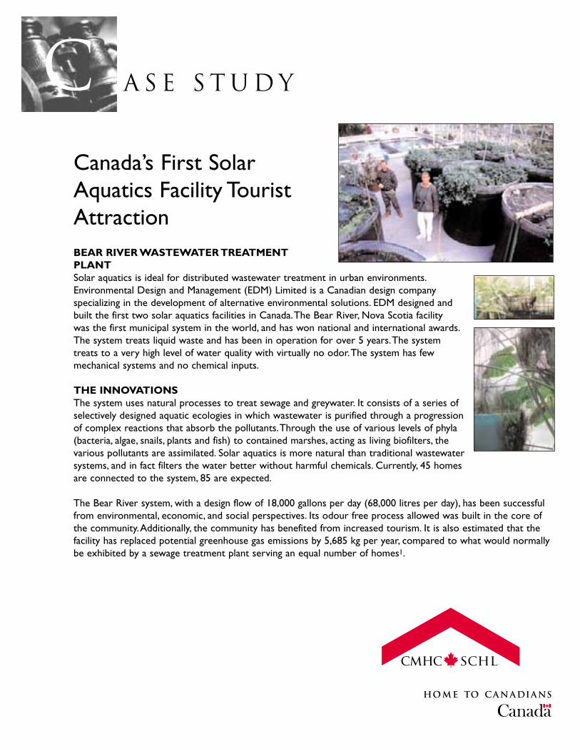
A S E S T U D YCCanada’s First SolarAquatics Facility TouristAttractionBEAR RIVER WASTEWATER TREATMENTPLANTSolar aquatics is ideal for distributed wastewater treatment in urban environments.Environmental Design and Management (EDM) Limited is a Canadian design companyspecializing in the development of alternative environmental solutions. EDM designed andbuilt the first two solar aquatics facilities in Canada.The Bear River, Nova Scotia facility was the first municipal system in the world, and has won national and international awards.The system treats liquid waste and has been in operation for over 5 years.The systemtreats to a very high level of water quality with virtually no odor.The system has fewmechanical systems and no chemical inputs.
THE INNOVATIONSThe system uses natural processes to treat sewage and greywater. It consists of a series ofselectively designed aquatic ecologies in which wastewater is purified through a progressionof complex reactions that absorb the pollutants.Through the use of various levels of phyla(bacteria, algae, snails, plants and fish) to contained marshes, acting as living biofilters, thevarious pollutants are assimilated. Solar aquatics is more natural than traditional wastewatersystems, and in fact filters the water better without harmful chemicals. Currently, 45 homes are connected to the system, 85 are expected.
The Bear River system, with a design flow of 18,000 gallons per day (68,000 litres per day), has been successfulfrom environmental, economic, and social perspectives. Its odour free process allowed was built in the core ofthe community.Additionally, the community has benefited from increased tourism. It is also estimated that thefacility has replaced potential greenhouse gas emissions by 5,685 kg per year, compared to what would normallybe exhibited by a sewage treatment plant serving an equal number of homes1.

The plant cost under $400,000 to design and build. It was developedunder the National Infrastructure Program, with the capital cost beingshared between federal, provincial and municipal governments.The netcost to the Municipality was under $135,000, or approximately $4500 perconnected household.The cost-per-household is expected to decline bytwo-thirds with future expansions.The operating costs of the plant areestimated at $45,000-60,000. However, in the future, operating costs areexpected to decrease to about $25,000 per year.
1 http://www.climatechangesolutions.com/english/municipal/stories/default.htmphotographs courtesy of Kimron Rink.
Project Info
Location: Bear River, Canada
Designer: Environmental Design and Management
Number of Dwellings: 45-50 Houses approx. 800 residents
Facility Floor Area: 222 m2 (2400 ft2)
Completion Date: 1995
Cost: $600,000
Further Information: County of AnnapolisP.O. Box 100,Annapolis Royal,Nova Scotia,Canada B0S 1A0 Phone:(902) 532-2331 FAX: (902) 532-2096 Web:http://www.annapoliscounty.ns.ca/solaraqu.htm
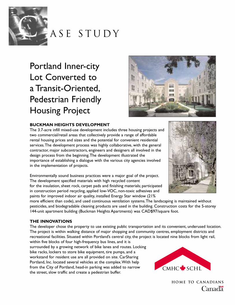
A S E S T U D YCPortland Inner-city Lot Converted to a Transit-Oriented,Pedestrian FriendlyHousing ProjectBUCKMAN HEIGHTS DEVELOPMENTThe 3.7-acre infill mixed-use development includes three housing projects andtwo commercial/retail areas that collectively provide a range of affordablerental housing prices and sizes and the potential for convenient residentialservices.The development process was highly collaborative, with the generalcontractor, major subcontractors, engineers and designers all involved in thedesign process from the beginning.The development illustrated theimportance of establishing a dialogue with the various city agencies involvedin the implementation of projects.
Environmentally sound business practices were a major goal of the project.The development specified materials with high recycled content for the insulation, sheet rock, carpet pads and finishing materials; participatedin construction period recycling, applied low-VOC, non-toxic adhesives andpaints for improved indoor air quality, installed Energy Star window (21%more efficient than code), and used continuous ventilation systems.The landscaping is maintained withoutpesticides, and biodegradable cleaning products are used in the building. Construction costs for the 5-storey144-unit apartment building (Buckman Heights Apartments) was CAD$97/square foot.
THE INNOVATIONSThe developer chose the property to use existing public transportation and its convenient, underused location.The project is within walking distance of major shopping and community centres, employment districts andrecreational facilities. Situated within Portland’s central city, the project is located nine blocks from light rail,within five blocks of four high-frequency bus lines, and it issurrounded by a growing network of bike lanes and routes. Lockingbike racks, lockers to store bike equipment, tire pumps, and aworkstand for resident use are all provided on site. CarSharingPortland, Inc. located several vehicles at the complex.With help from the City of Portland, head-in parking was added to narrow the street, slow traffic and create a pedestrian buffer.
Water use and stormwater management are addressed with low-flowplumbing fixtures and Best Management Practices (BMPs) forstormwater retention.Approximately 95% of stormwater is retainedon-site (half of the site possesses 100% on-site retention, the otherhalf experiences 80-90% on-site retention). Stormwater BMPs includenarrow driveways, several bioswales, a 185 m2 extensive green roof,permeable surfaces and a back-up dry well.
Project Info
Location: Portland, USA
Architect: William Wilson Architects
Site Area: 3.7 Acres
Number of Dwellings: Buckman Heights Apartments: 144Buckman Terrace:122 Buckman Townhouses: 8
Commercial/Retail Floor Areas: 185 m2, 3810 m2
Completion Date: 1998
Further Information: Ed McnamaraPrendergast & Associates333 SW Fifth AvenuePortland, OregonUSA 97204Phone: 503-223-8724
A S E S T U D YCHalifax Leads Canada in Waste Diversion andCompostingHALIFAX REGIONAL MUNICIPALITYOrganised opposition to a failed landfill and a proposed incinerator resulted in one of the most innovative solidwaste management systems in North America.The Halifax Regional Municipality (HRM) has a population base of350,000, with annual waste generation of 260,000 metric tonnes. In the early 1990s, after years of usage, the wetlandarea landfill servicing the region, was discovered to have had caused severe environmental damage that affectednearby residents. Ultimately, the HRM compensated the community, approximately $5 million, and bought adjacenthomes.The situation prompted a review process to determine a new waste management strategy and resulted in theHRM advanced municipal solid waste management system.This system has significantly reduced the amount of wastethat goes to landfill.About 1.4 tonnes less waste per resident, compared to 1995, reached the municipality’s landfillsite.This represents a 61.5% reduction from 1989 per person volumes.There was also a decrease of approximately0.5 megatonnes of carbon dioxide equivalent GHG emissions.
The new system did not require a property tax increase. Capital costs of $70.1 million, were financed through a mixture of public and private capital, along with design/build/operate contracts with the private sector.Whileoperating costs for the new systems have been more expensive than the old system, $32.5 million per yearcompared to $23.4 million, both public and governmental bodies are satisfied with the new system, and considerthe additional costs incurred justifiable.Also, a significant portion of the total operating costs (approximately33%) are recovered through tipping fees1, and 125 jobs were created through public / private partnerships.
INNOVATIONSThe HRM solid waste management system includes the following:
• Residents are asked to separate their waste into recyclables, compostables and hazardous materials, andother residual refuse.The municipality provides blue bags and aerated carts, and either weekly or biweeklypick-up services.
• Eight collection zones were created (from a previous 25) with six haulers. (The biweekly collection schedulemakes it feasible to still use one truck for trash and organics.) The HRM set up a mass balance flow betweenthe eight zones. Organics are collected from four zones one week, and the other four the next.Trash iscollected from each of the four on the alternating weeks.
• One site that includes a mixed waste processing facility designed tohandle 119,000 metric tons/year of MSW; a 13 channel agitated bedcomposting system to process the mixed waste after recyclablesare removed; and a landfill for stabilized waste.
• Two separate composting facilities with total processing capacity of61,000 metric tons/year. Both of theses facilities are privatelyowned and operated, each with put or pay guarantees

($68.60/metric ton to one compost facility and $65.50 to the other) byHRM of 20,000 metric tons/year.
• Expansion of an existing materials recovery facility.
The recyclable materials are processed at the materials recovery facility (MRF),while the compostables are processed at the two composting facilities. Residualrefuse is handled at the mixed waste processing facility. Before residual waste islandfilled it is passed along conveyor lines, where any remaining recyclablematerials are removed by hand, and the remaining material is then ground intosmall pieces and transferred to an 18-day composting plant, to ensure that anyresidual putrescible material is rendered inert.Anything remaining after thisprocess is then transferred to the new, virtually methane-free, residual disposalfacility that has no odour problem, does not attract vermin or birds, and doesnot require an on-site leachate collection system.
During the new system’s first nine months of operation, from January toSeptember 1999, the amount of waste that required landfilling was 40% lessthan the previous year. However, the amount of commercial, industrial andinstitutional waste (ICI) (including waste from apartment buildings) fell only byeight per cent, resulting in some waste being temporarily exported to theneighbouring Queens region for landfilling.While the ICI sector is responsiblefor its own waste collection, the HRM does encourage the separation ofcompostables at source in two ways: (1) by setting differential tipping fees($68/tonne for compostables and $110/tonne for residual refuse); and (2) byreserving the right to refuse unsorted loads that are delivered to the front-end processing/ waste stabilisation facility.Today, the total solid waste stream isroughly 55 percent residential and 45 percent commercial.
Not all of the 260,000 metric tons generated annually will go through thenew HRM system. Construction and demolition debris, which accounts for40,000 to 60,000 metric tons/year, and recyclables from the commercialsector go to private operators.This leaves roughly 190,000 for the HRMfacilities and contractors to process.The design capacity is for 460 tons/dayto come into the front end of the mixed waste facility. Even if the facilityover capacity on the front-end, it can not dispose of anything directly intothe landfill.
1 Assumes $32.5 million operating costs and tipping revenues of $10.6 million (projected 2000/01).
Project Info
Location: Halifax Regional Municipality (HRM), Nova Scotia
Implementation Date: 1999
Further Information: Brian T. SmithHalifax Regional MunicipalitySolid Waste Resources2776 Dutch Village RoadP.O. Box 1749Halifax, NS B3J 3A5Phone: 902-490-6600