healthcare ventilation, “high consequence spaces”...healthcare ventilation, “high consequence...
TRANSCRIPT

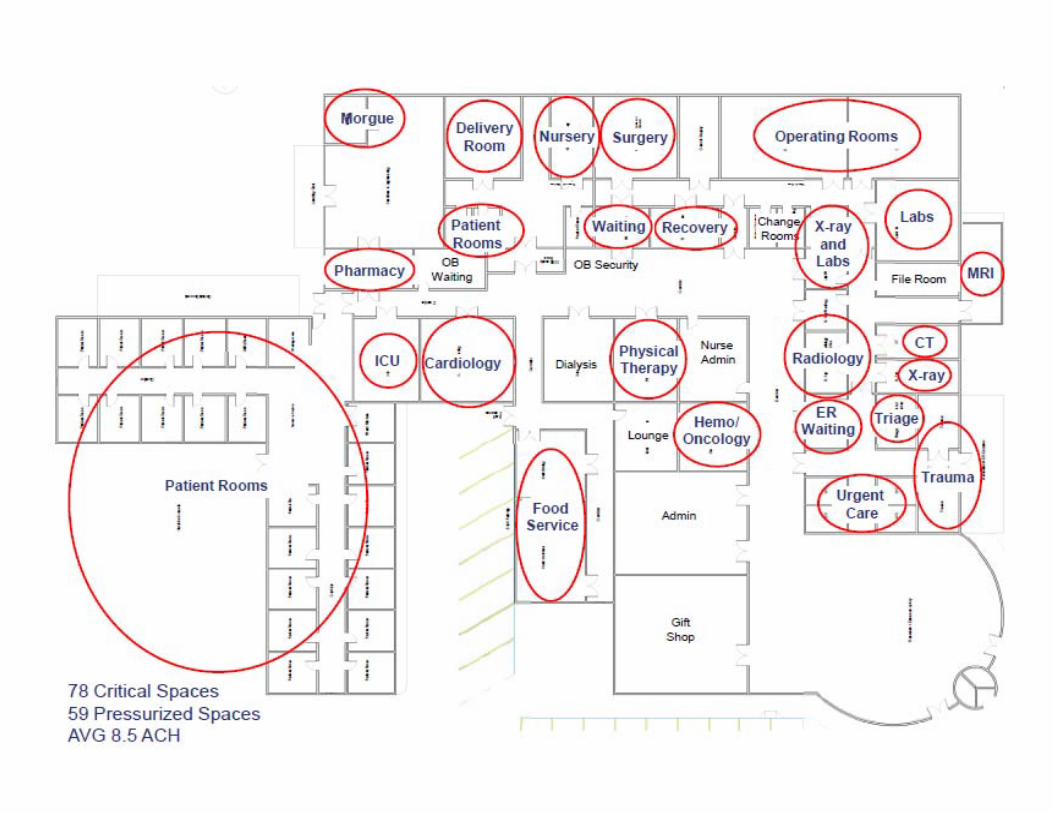
Healthcare Ventilation, “High Consequence Spaces”
Healthcare EnvironmentsMiSHE Chapter
Don MacDonald, Phoenix ControlsSeptember 28, 2017
Healthcare Ventilation, “High Consequence Spaces”
I. Industry ChallengesII. Standards and Guidelines
I. USP 800 update
III. ApplicationsIV. Energy Management TrendsV. Optimizer Simulation Analysis
Software VI. Case StudiesVII. Summary
Presentation Outline
Presented by:
Don MacDonaldNorthern Regional ManagerPhoenix ControlsCell: 519‐212‐[email protected]

INDUSTRY CHALLENGES
Presentation and Discussion
Energy Challenges
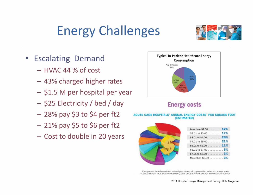
• Escalating Demand– HVAC 44 % of cost– 43% charged higher rates– $1.5 M per hospital per year– $25 Electricity / bed / day– 28% pay $3 to $4 per ft2– 21% pay $5 to $6 per ft2– Cost to double in 20 years
2011 Hospital Energy Management Survey, HFM Magazine
Energy Challenges
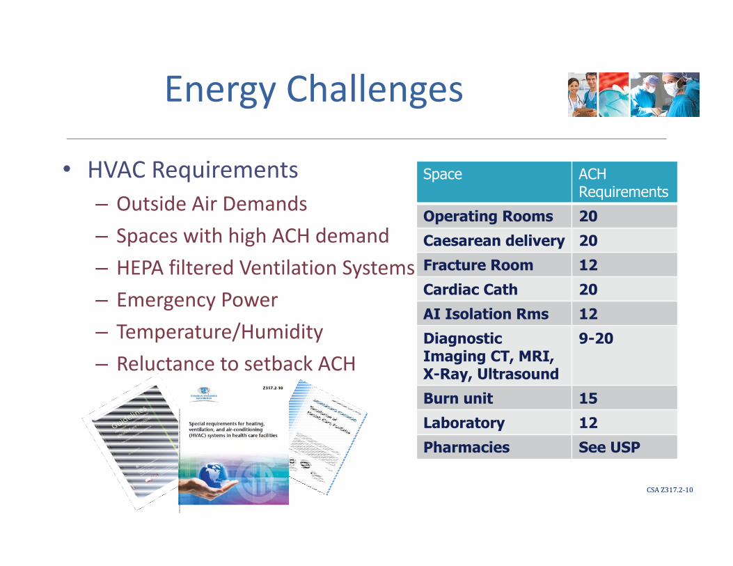
• HVAC Requirements– Outside Air Demands – Spaces with high ACH demand– HEPA filtered Ventilation Systems – Emergency Power– Temperature/Humidity– Reluctance to setback ACH
CSAZ317.2‐10
Space ACH Requirements
Operating Rooms 20Caesarean delivery 20Fracture Room 12Cardiac Cath 20AI Isolation Rms 12Diagnostic Imaging CT, MRI, X-Ray, Ultrasound
9-20
Burn unit 15Laboratory 12Pharmacies See USP
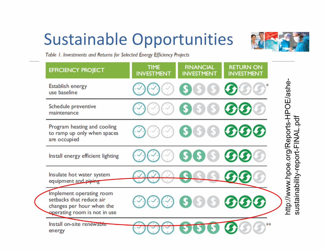
Sustainable Opportunities
http
://w
ww.
hpoe
.org
/Rep
orts
-HPO
E/as
he-
sust
aina
bilit
y-re
port-
FIN
AL.p
df
HVAC VENTILATION DESIGN CHALLENGES
Presentation and Discussion
Ventilation Design Challenges
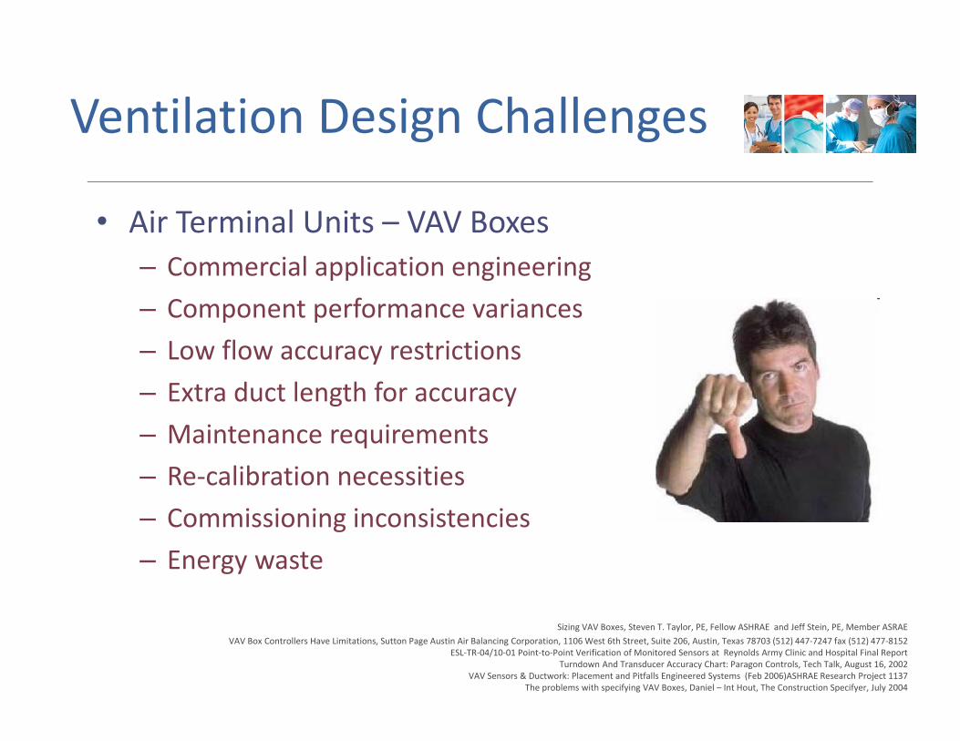
• Air Terminal Units – VAV Boxes– Commercial application engineering– Component performance variances– Low flow accuracy restrictions– Extra duct length for accuracy– Maintenance requirements– Re‐calibration necessities– Commissioning inconsistencies– Energy waste
Sizing VAV Boxes, Steven T. Taylor, PE, Fellow ASHRAE and Jeff Stein, PE, Member ASRAEVAV Box Controllers Have Limitations, Sutton Page Austin Air Balancing Corporation, 1106 West 6th Street, Suite 206, Austin, Texas 78703 (512) 447‐7247 fax (512) 477‐8152
ESL‐TR‐04/10‐01 Point‐to‐Point Verification of Monitored Sensors at Reynolds Army Clinic and Hospital Final ReportTurndown And Transducer Accuracy Chart: Paragon Controls, Tech Talk, August 16, 2002
VAV Sensors & Ductwork: Placement and Pitfalls Engineered Systems (Feb 2006)ASHRAE Research Project 1137The problems with specifying VAV Boxes, Daniel – Int Hout, The Construction Specifyer, July 2004
Ventilation Design Challenges
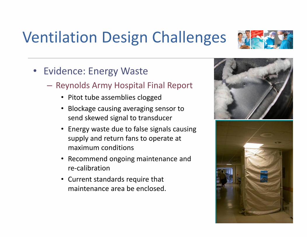
• Evidence: Energy Waste– Reynolds Army Hospital Final Report
• Pitot tube assemblies clogged• Blockage causing averaging sensor to send skewed signal to transducer
• Energy waste due to false signals causing supply and return fans to operate at maximum conditions
• Recommend ongoing maintenance and re‐calibration
• Current standards require that maintenance area be enclosed.
ESL-TR-04/10-01 Point-to-Point Verification
of Monitored Sensors

STANDARDS & GUIDELINESPresentation and Discussion
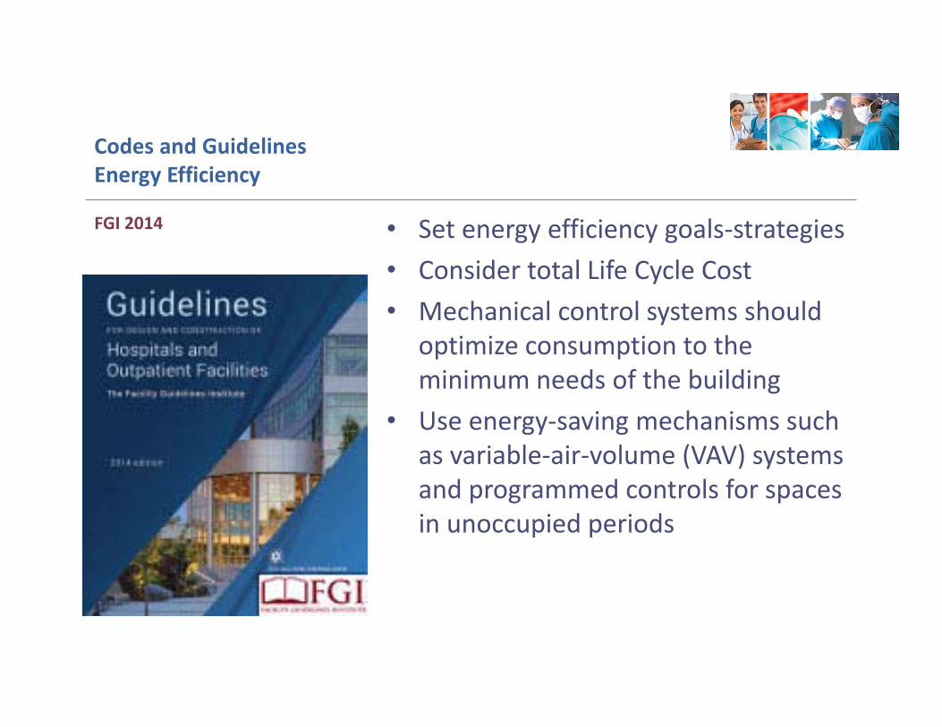
Codes and GuidelinesEnergy Efficiency
• Set energy efficiency goals‐strategies• Consider total Life Cycle Cost• Mechanical control systems should
optimize consumption to the minimum needs of the building
• Use energy‐saving mechanisms such as variable‐air‐volume (VAV) systems and programmed controls for spaces in unoccupied periods
FGI 2014
Codes and GuidelinesEnergy Efficiency
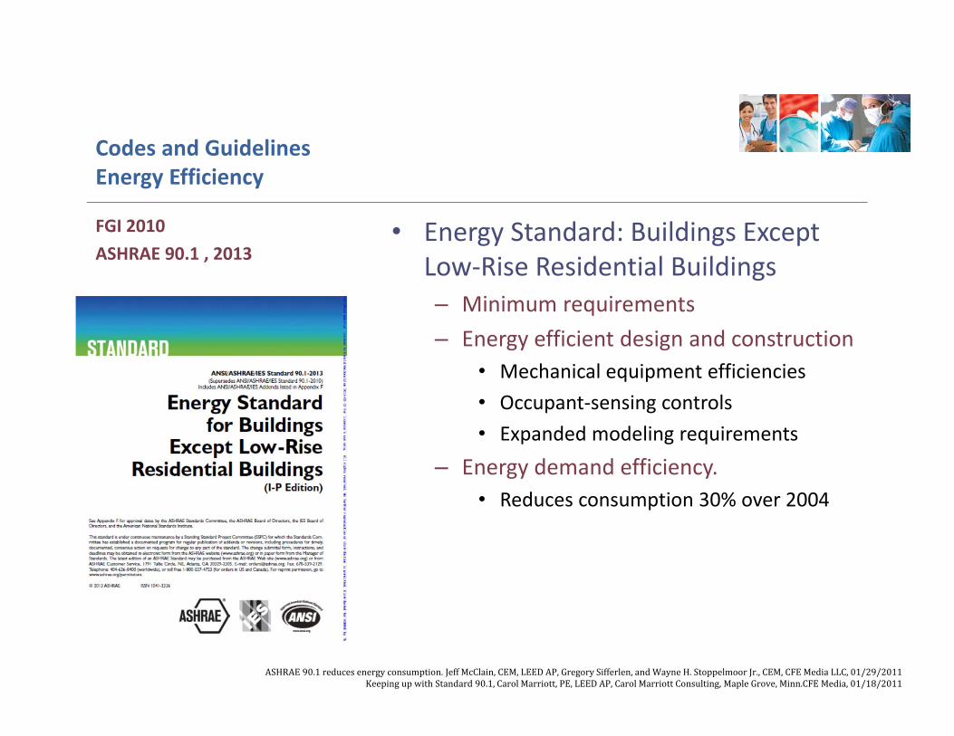
• Energy Standard: Buildings Except Low‐Rise Residential Buildings– Minimum requirements– Energy efficient design and construction
• Mechanical equipment efficiencies • Occupant‐sensing controls • Expanded modeling requirements
– Energy demand efficiency.• Reduces consumption 30% over 2004
FGI 2010ASHRAE 90.1 , 2013
ASHRAE90.1reducesenergyconsumption.JeffMcClain,CEM,LEEDAP,GregorySifferlen,andWayneH.StoppelmoorJr.,CEM,CFE MediaLLC,01/29/2011KeepingupwithStandard90.1,CarolMarriott,PE,LEEDAP,CarolMarriottConsulting,MapleGrove,Minn.CFEMedia,01/18/2011
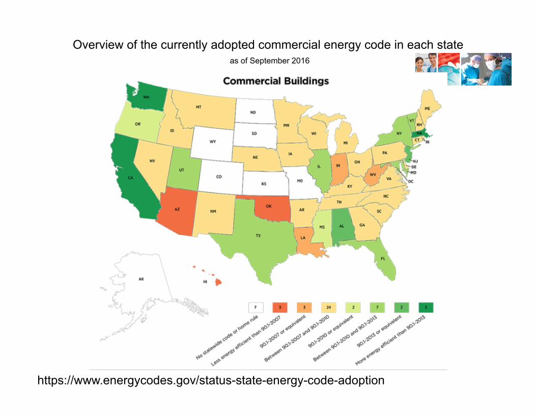
Overview of the currently adopted commercial energy code in each state as of September 2016
https://www.energycodes.gov/status-state-energy-code-adoption
Codes and GuidelinesEnergy Efficiency
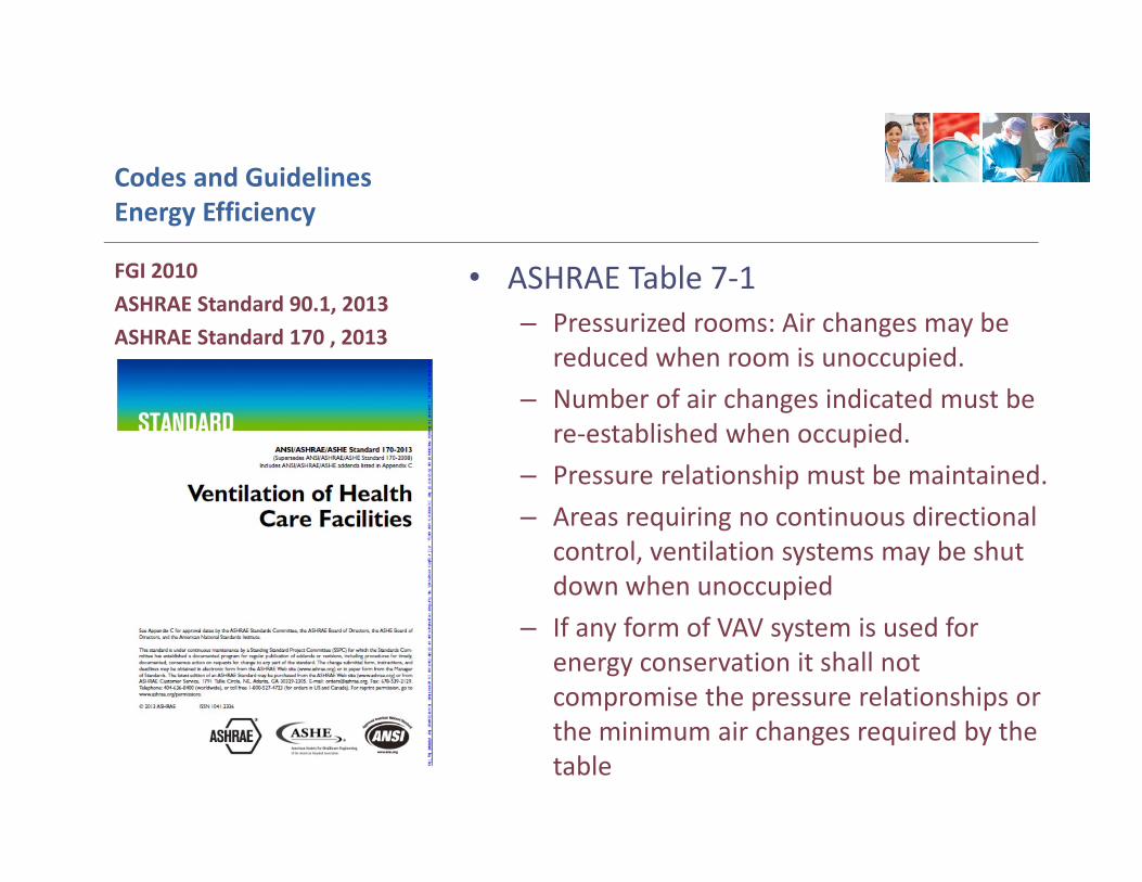
• ASHRAE Table 7‐1– Pressurized rooms: Air changes may be
reduced when room is unoccupied. – Number of air changes indicated must be
re‐established when occupied.– Pressure relationship must be maintained.– Areas requiring no continuous directional
control, ventilation systems may be shut down when unoccupied
– If any form of VAV system is used for energy conservation it shall not compromise the pressure relationships or the minimum air changes required by the table
FGI 2010ASHRAE Standard 90.1, 2013 ASHRAE Standard 170 , 2013
Codes and GuidelinesEnergy Efficiency
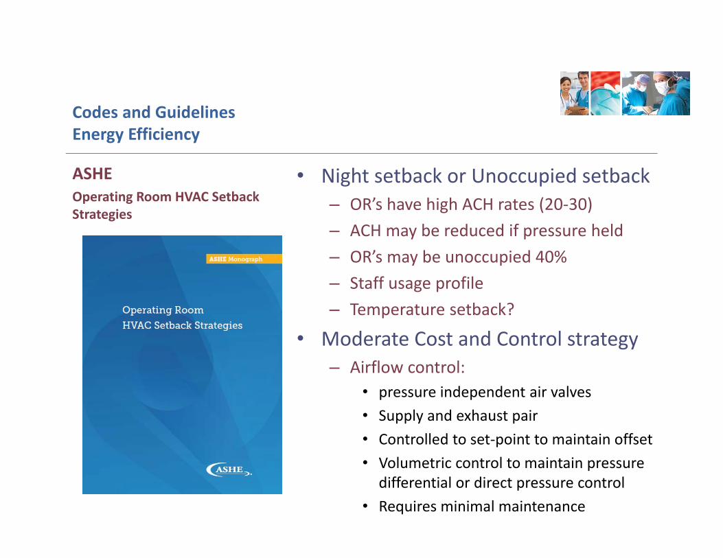
• Night setback or Unoccupied setback– OR’s have high ACH rates (20‐30)– ACH may be reduced if pressure held– OR’s may be unoccupied 40%– Staff usage profile– Temperature setback?
• Moderate Cost and Control strategy– Airflow control:
• pressure independent air valves• Supply and exhaust pair• Controlled to set‐point to maintain offset• Volumetric control to maintain pressure
differential or direct pressure control• Requires minimal maintenance
ASHE Operating Room HVAC Setback Strategies
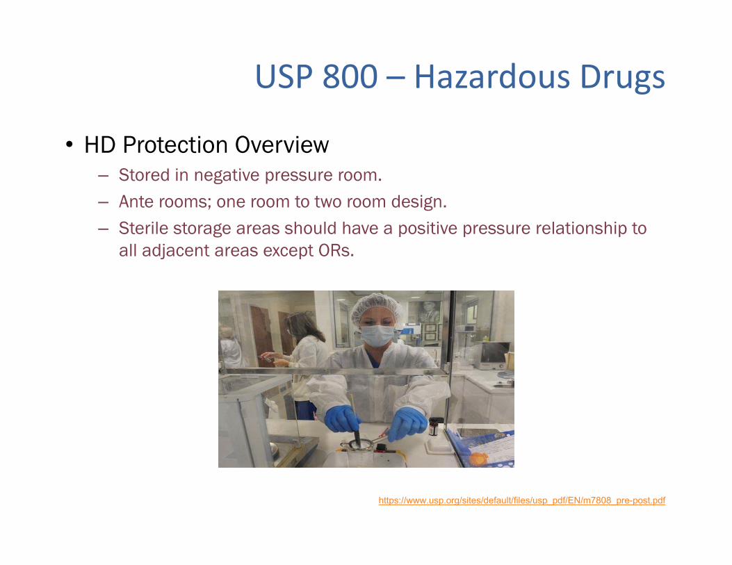
• HD Protection Overview– Stored in negative pressure room.– Ante rooms; one room to two room design.– Sterile storage areas should have a positive pressure relationship to
all adjacent areas except ORs.
USP 800 – Hazardous Drugs
https://www.usp.org/sites/default/files/usp_pdf/EN/m7808_pre-post.pdf
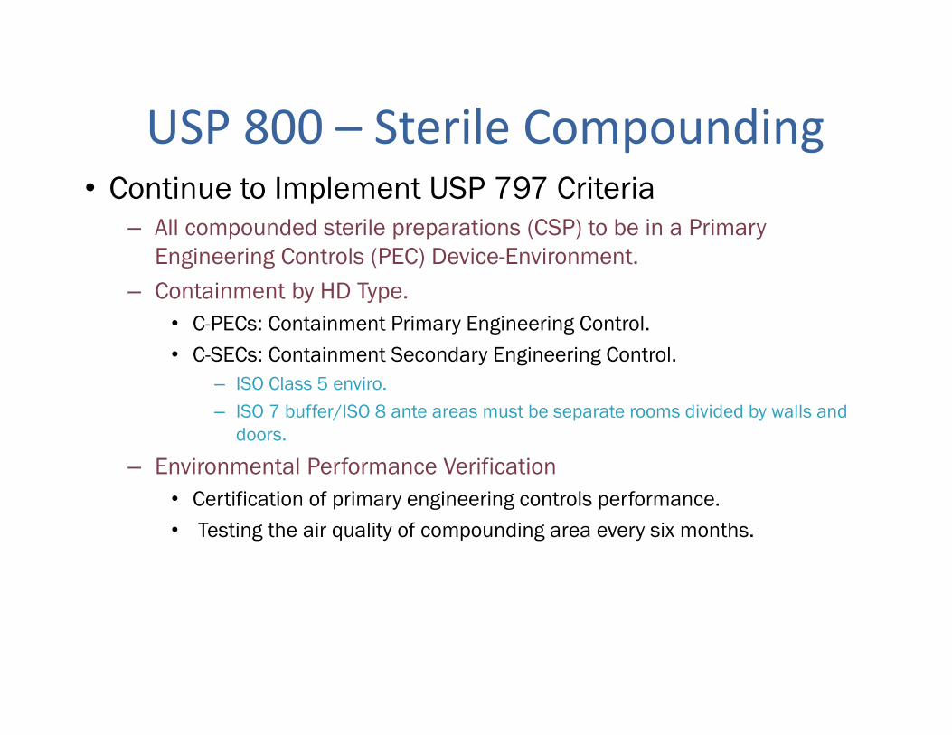
• Continue to Implement USP 797 Criteria– All compounded sterile preparations (CSP) to be in a Primary
Engineering Controls (PEC) Device-Environment.– Containment by HD Type.
• C-PECs: Containment Primary Engineering Control.• C-SECs: Containment Secondary Engineering Control.
– ISO Class 5 enviro.– ISO 7 buffer/ISO 8 ante areas must be separate rooms divided by walls and
doors.
– Environmental Performance Verification• Certification of primary engineering controls performance.• Testing the air quality of compounding area every six months.
USP 800 – Sterile Compounding
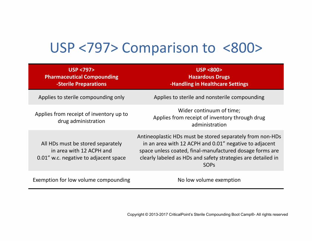
USP <797> Comparison to <800>USP <797>
Pharmaceutical Compounding ‐Sterile Preparations
USP <800>Hazardous Drugs
‐Handling in Healthcare Settings
Applies to sterile compounding only Applies to sterile and nonsterile compounding
Applies from receipt of inventory up to drug administration
Wider continuum of time;Applies from receipt of inventory through drug
administration
All HDs must be stored separatelyin area with 12 ACPH and
0.01” w.c. negative to adjacent space
Antineoplastic HDs must be stored separately from non‐HDs in an area with 12 ACPH and 0.01” negative to adjacent
space unless coated, final‐manufactured dosage forms are clearly labeled as HDs and safety strategies are detailed in
SOPs
Exemption for low volume compounding No low volume exemption
Copyright © 2013-2017 CriticalPoint’s Sterile Compounding Boot Camp®- All rights reserved
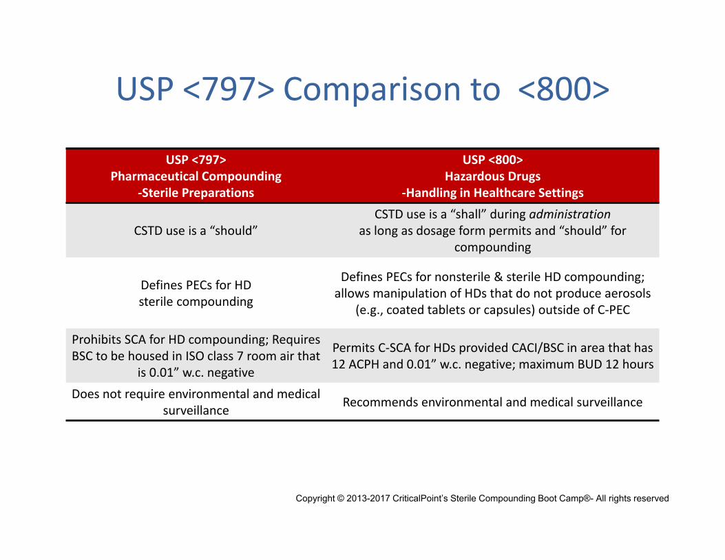
USP <797> Comparison to <800>
USP <797>Pharmaceutical Compounding
‐Sterile Preparations
USP <800>Hazardous Drugs
‐Handling in Healthcare Settings
CSTD use is a “should”CSTD use is a “shall” during administration
as long as dosage form permits and “should” for compounding
Defines PECs for HDsterile compounding
Defines PECs for nonsterile & sterile HD compounding; allows manipulation of HDs that do not produce aerosols
(e.g., coated tablets or capsules) outside of C‐PEC
Prohibits SCA for HD compounding; Requires BSC to be housed in ISO class 7 room air that
is 0.01” w.c. negative
Permits C‐SCA for HDs provided CACI/BSC in area that has 12 ACPH and 0.01” w.c. negative; maximum BUD 12 hours
Does not require environmental and medical surveillance Recommends environmental and medical surveillance
Copyright © 2013-2017 CriticalPoint’s Sterile Compounding Boot Camp®- All rights reserved
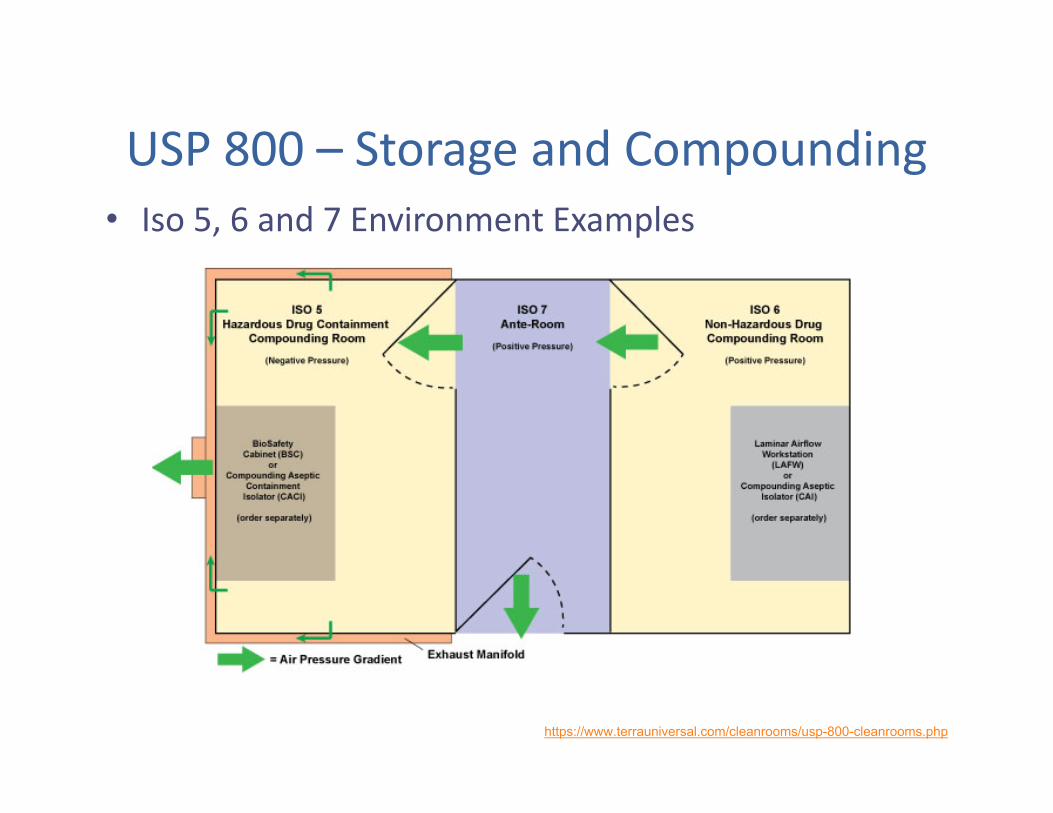
USP 800 – Storage and Compounding• Iso 5, 6 and 7 Environment Examples
https://www.terrauniversal.com/cleanrooms/usp-800-cleanrooms.php
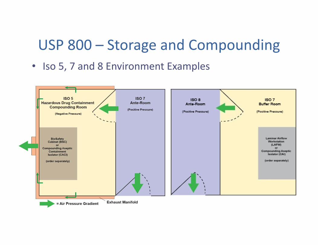
USP 800 – Storage and Compounding• Iso 5, 7 and 8 Environment Examples
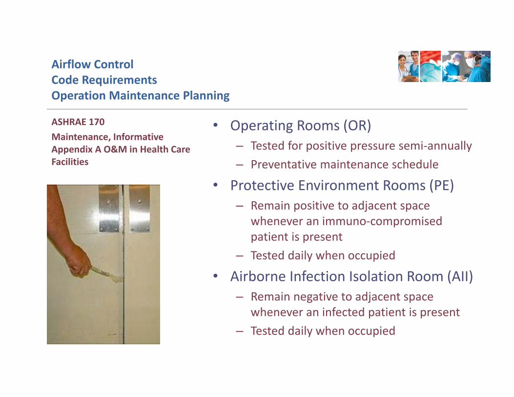
Airflow ControlCode Requirements Operation Maintenance Planning
• Operating Rooms (OR)– Tested for positive pressure semi‐annually– Preventative maintenance schedule
• Protective Environment Rooms (PE) – Remain positive to adjacent space
whenever an immuno‐compromised patient is present
– Tested daily when occupied
• Airborne Infection Isolation Room (AII) – Remain negative to adjacent space
whenever an infected patient is present– Tested daily when occupied
ASHRAE 170 Maintenance, Informative Appendix A O&M in Health Care Facilities
VENTILATION APPLICATIONSPresentation and Discussion
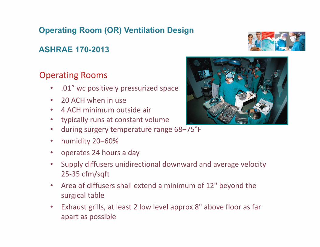
Operating Rooms• .01” wc positively pressurized space• 20 ACH when in use• 4 ACH minimum outside air• typically runs at constant volume• during surgery temperature range 68‒75°F• humidity 20‒60%• operates 24 hours a day• Supply diffusers unidirectional downward and average velocity
25‐35 cfm/sqft• Area of diffusers shall extend a minimum of 12" beyond the
surgical table• Exhaust grills, at least 2 low level approx 8" above floor as far
apart as possible
Operating Room (OR) Ventilation Design
ASHRAE 170-2013
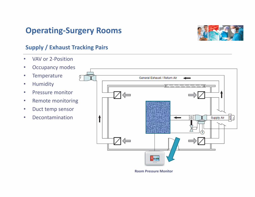
Operating‐Surgery Rooms
Supply / Exhaust Tracking Pairs
Room Pressure Monitor
• VAV or 2‐Position • Occupancy modes • Temperature• Humidity• Pressure monitor• Remote monitoring• Duct temp sensor• Decontamination
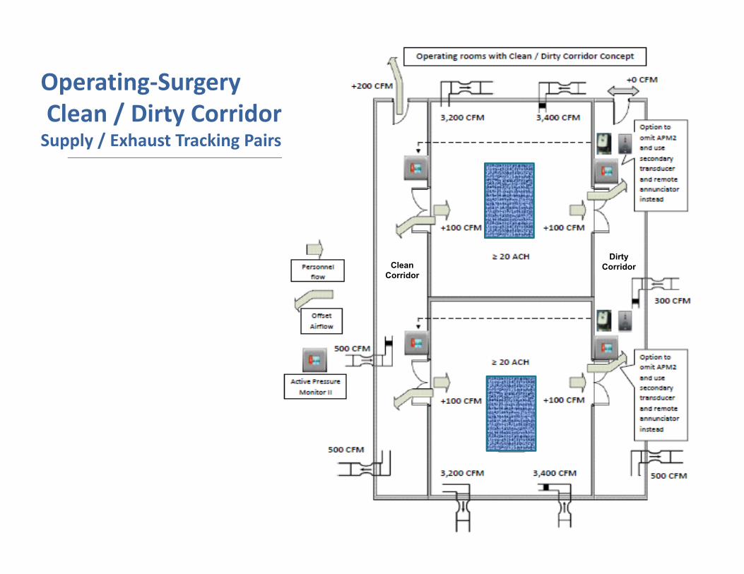
Operating‐SurgeryClean / Dirty CorridorSupply / Exhaust Tracking Pairs
CleanCorridor
DirtyCorridor
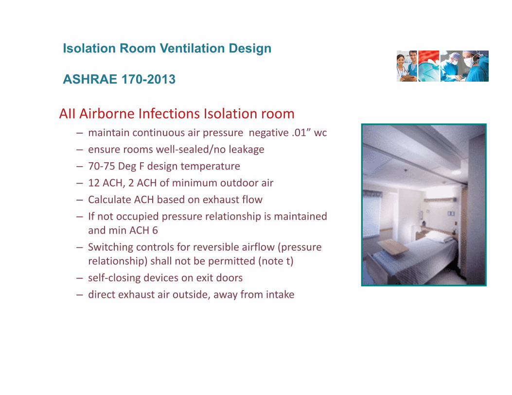
AII Airborne Infections Isolation room– maintain continuous air pressure negative .01” wc– ensure rooms well‐sealed/no leakage– 70‐75 Deg F design temperature– 12 ACH, 2 ACH of minimum outdoor air– Calculate ACH based on exhaust flow– If not occupied pressure relationship is maintained
and min ACH 6– Switching controls for reversible airflow (pressure
relationship) shall not be permitted (note t)– self‐closing devices on exit doors– direct exhaust air outside, away from intake
Isolation Room Ventilation Design
ASHRAE 170-2013
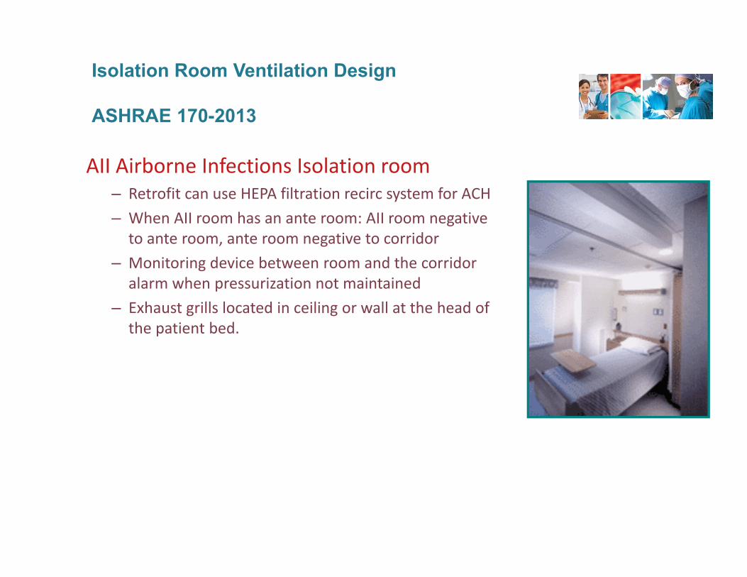
AII Airborne Infections Isolation room– Retrofit can use HEPA filtration recirc system for ACH– When AII room has an ante room: AII room negative
to ante room, ante room negative to corridor– Monitoring device between room and the corridor
alarm when pressurization not maintained– Exhaust grills located in ceiling or wall at the head of
the patient bed.
Isolation Room Ventilation Design
ASHRAE 170-2013
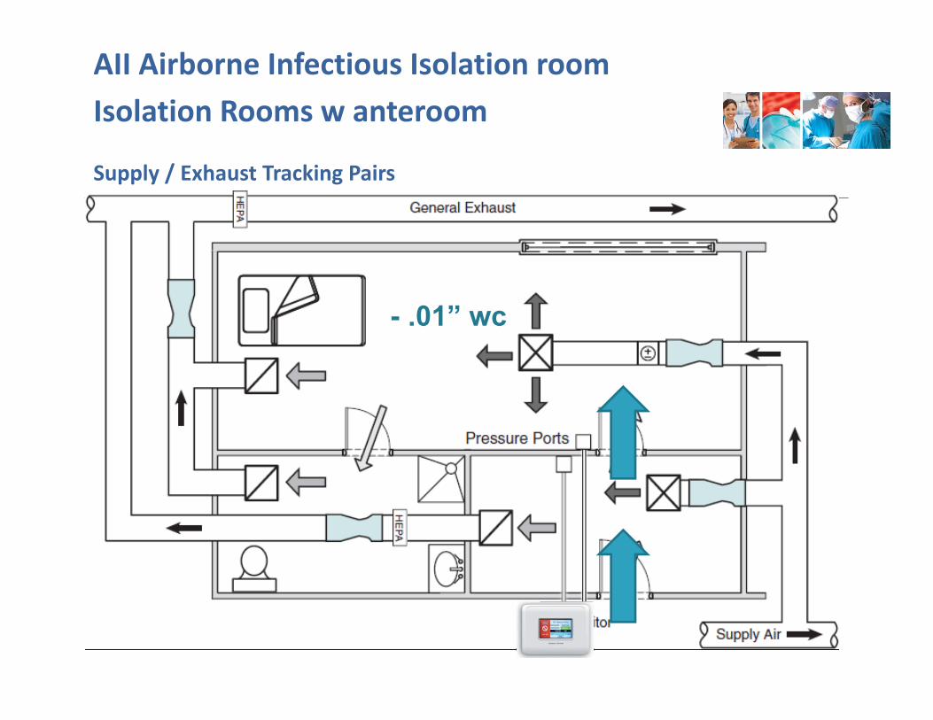
Isolation Rooms w anteroom
Supply / Exhaust Tracking Pairs
• CV, VAV or 2‐Position • High turndown• APM2 pressure monitor• Remote monitoring• Occupancy modes • Temperature control• Duct temperature sensor
AII Airborne Infectious Isolation room
- .01” wc
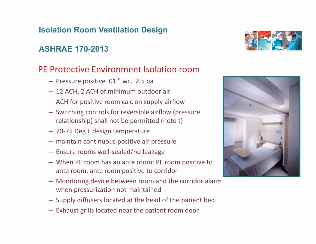
PE Protective Environment Isolation room– Pressure positive .01 " wc. 2.5 pa– 12 ACH, 2 ACH of minimum outdoor air– ACH for positive room calc on supply airflow– Switching controls for reversible airflow (pressure
relationship) shall not be permitted (note t)– 70‐75 Deg F design temperature– maintain continuous positive air pressure– Ensure rooms well‐sealed/no leakage– When PE room has an ante room: PE room positive to
ante room, ante room positive to corridor– Monitoring device between room and the corridor alarm
when pressurization not maintained– Supply diffusers located at the head of the patient bed.– Exhaust grills located near the patient room door.
Isolation Room Ventilation Design
ASHRAE 170-2013
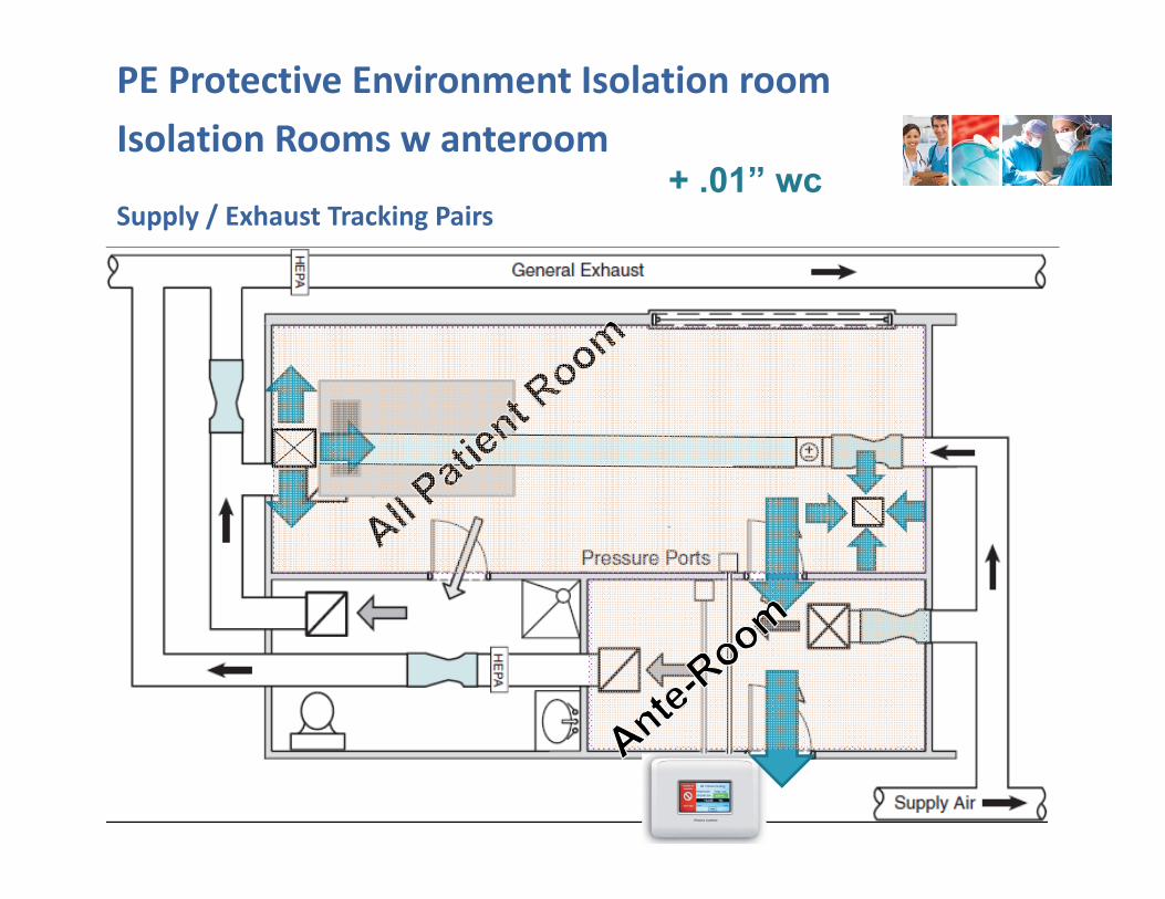
Isolation Rooms w anteroom
Supply / Exhaust Tracking Pairs
PE Protective Environment Isolation room
+ .01” wc
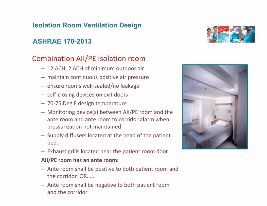
Combination AII/PE Isolation room– 12 ACH, 2 ACH of minimum outdoor air– maintain continuous positive air pressure– ensure rooms well‐sealed/no leakage– self‐closing devices on exit doors– 70‐75 Deg F design temperature– Monitoring device(s) between AII/PE room and the
ante room and ante room to corridor alarm when pressurization not maintained
– Supply diffusers located at the head of the patient bed.
– Exhaust grills located near the patient room doorAII/PE room has an ante room:– Ante room shall be positive to both patient room and
the corridor OR…..– Ante room shall be negative to both patient room
and the corridor
Isolation Room Ventilation Design
ASHRAE 170-2013
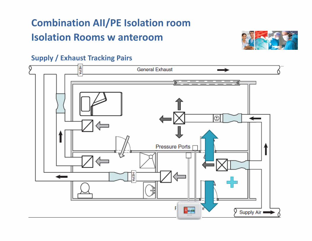
Isolation Rooms w anteroom
Supply / Exhaust Tracking Pairs
• CV, VAV or 2‐Position • High turndown• APM2 pressure monitor• Remote monitoring• Occupancy modes • Temperature control• Duct temperature sensor
Combination AII/PE Isolation room

Isolation Rooms w anteroom
Supply / Exhaust Tracking Pairs
• CV, VAV or 2‐Position • High turndown• APM2 pressure monitor• Remote monitoring• Occupancy modes • Temperature control• Duct temperature sensor
Combination AII/PE Isolation room
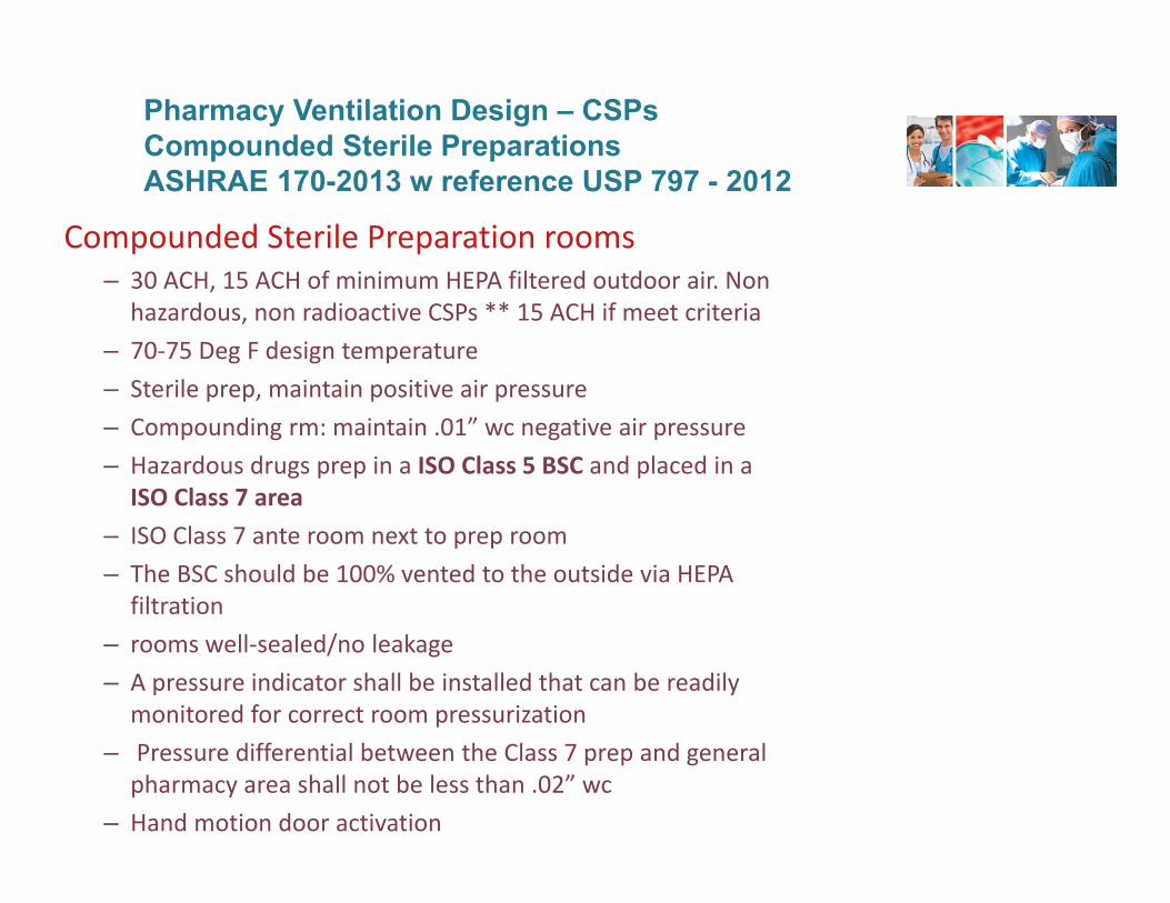
Compounded Sterile Preparation rooms– 30 ACH, 15 ACH of minimum HEPA filtered outdoor air. Non
hazardous, non radioactive CSPs ** 15 ACH if meet criteria– 70‐75 Deg F design temperature– Sterile prep, maintain positive air pressure– Compounding rm: maintain .01” wc negative air pressure– Hazardous drugs prep in a ISO Class 5 BSC and placed in a
ISO Class 7 area– ISO Class 7 ante room next to prep room– The BSC should be 100% vented to the outside via HEPA
filtration– rooms well‐sealed/no leakage– A pressure indicator shall be installed that can be readily
monitored for correct room pressurization– Pressure differential between the Class 7 prep and general
pharmacy area shall not be less than .02” wc– Hand motion door activation
Pharmacy Ventilation Design – CSPsCompounded Sterile PreparationsASHRAE 170-2013 w reference USP 797 - 2012
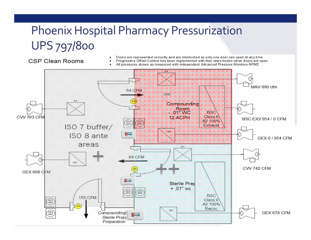
Phoenix Hospital Pharmacy PressurizationUPS 797/800
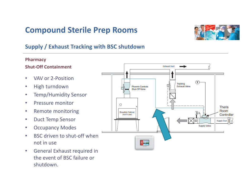
Compound Sterile Prep Rooms
Supply / Exhaust Tracking with BSC shutdown
• VAV or 2‐Position • High turndown • Temp/Humidity Sensor • Pressure monitor• Remote monitoring• Duct Temp Sensor • Occupancy Modes • BSC driven to shut‐off when
not in use• General Exhaust required in
the event of BSC failure or shutdown.
PharmacyShut‐Off Containment
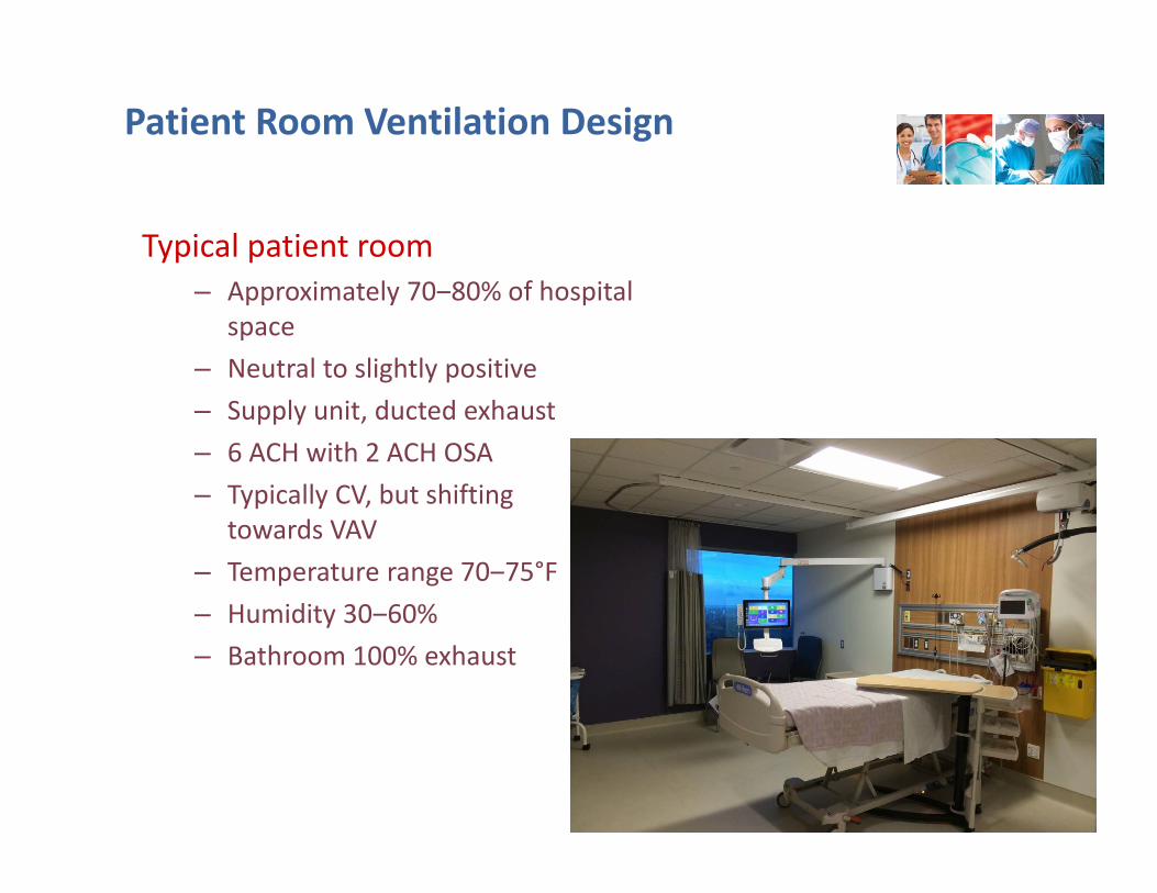
Typical patient room– Approximately 70‒80% of hospital
space – Neutral to slightly positive– Supply unit, ducted exhaust– 6 ACH with 2 ACH OSA– Typically CV, but shifting
towards VAV– Temperature range 70‒75°F– Humidity 30‒60%– Bathroom 100% exhaust
Patient Room Ventilation Design
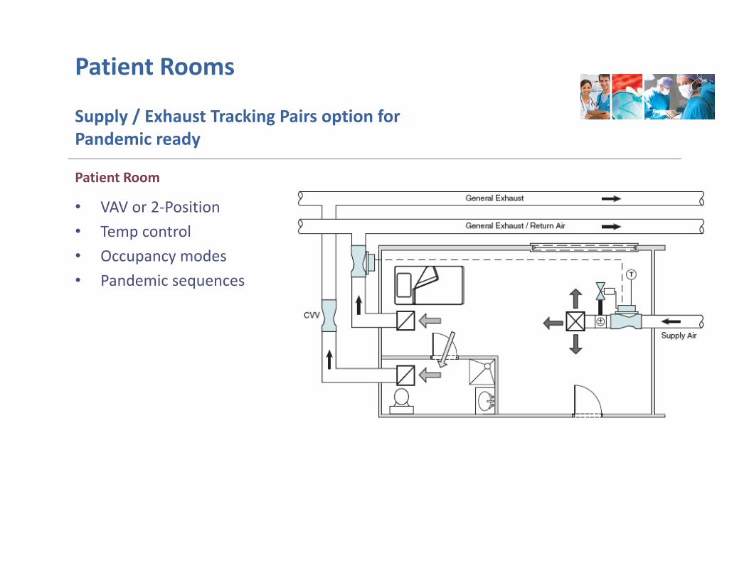
Patient Rooms
Supply / Exhaust Tracking Pairs option for Pandemic ready
• VAV or 2‐Position • Temp control• Occupancy modes • Pandemic sequences
Patient Room
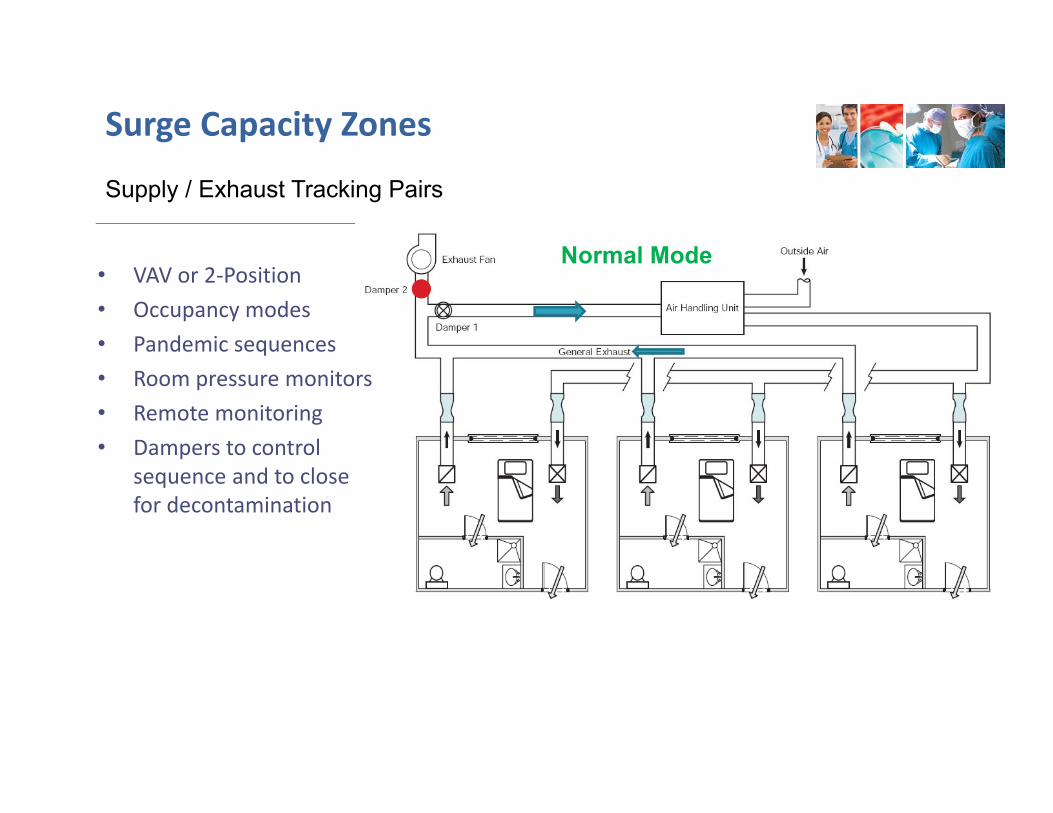
• VAV or 2‐Position • Occupancy modes • Pandemic sequences• Room pressure monitors• Remote monitoring• Dampers to control
sequence and to close for decontamination
Surge Capacity Zones
Supply / Exhaust Tracking Pairs
Normal Mode
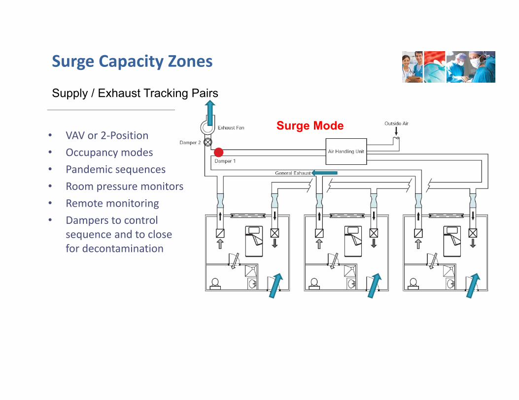
• VAV or 2‐Position • Occupancy modes • Pandemic sequences• Room pressure monitors• Remote monitoring• Dampers to control
sequence and to close for decontamination
Surge Capacity Zones
Supply / Exhaust Tracking Pairs
Surge Mode
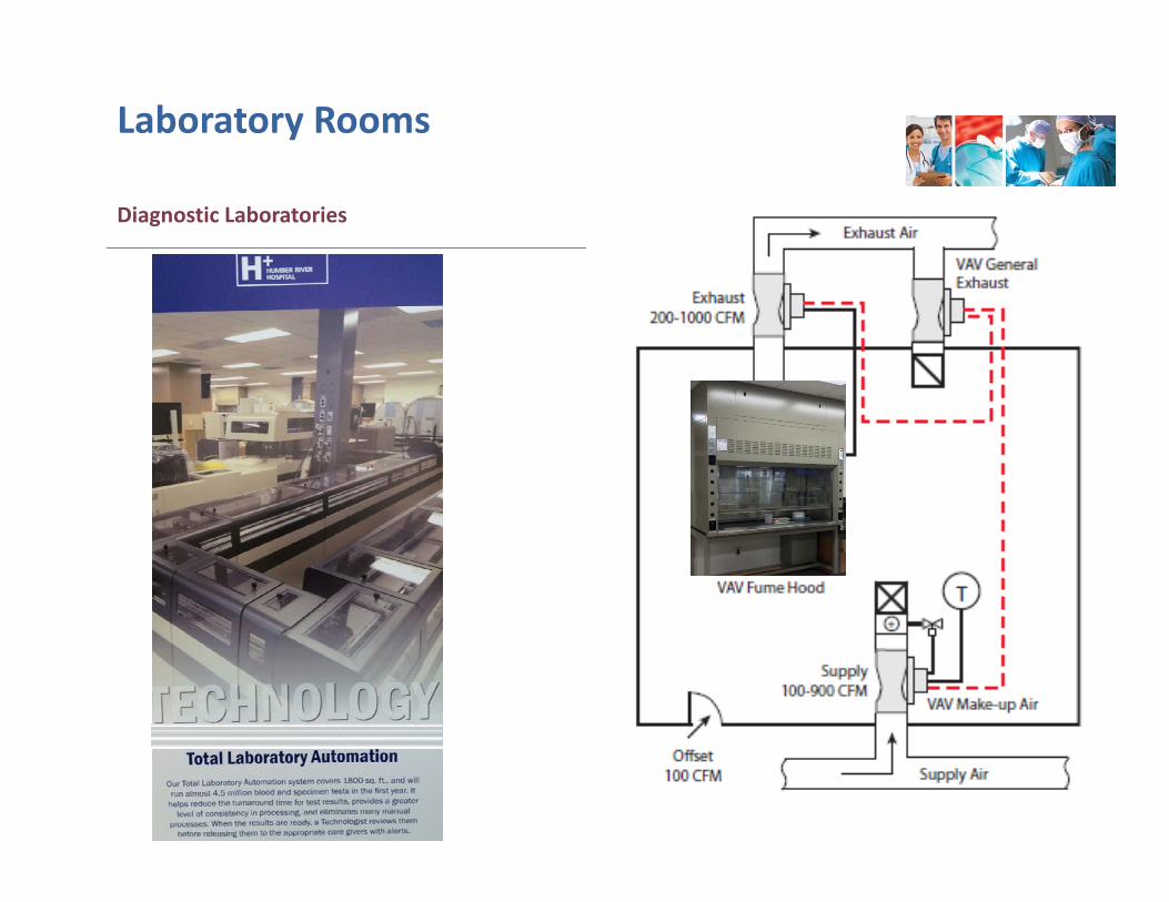
Diagnostic Laboratories
Laboratory Rooms
PROJECT CASE STUDIES
Presentation and Discussion
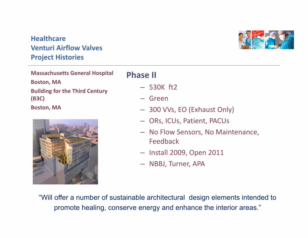
HealthcareVenturi Airflow Valves Project Histories
Phase II– 530K ft2– Green– 300 VVs, EO (Exhaust Only)– ORs, ICUs, Patient, PACUs– No Flow Sensors, No Maintenance,
Feedback– Install 2009, Open 2011– NBBJ, Turner, APA
Massachusetts General Hospital Boston, MABuilding for the Third Century (B3C)Boston, MA
“Will offer a number of sustainable architectural design elements intended topromote healing, conserve energy and enhance the interior areas.”
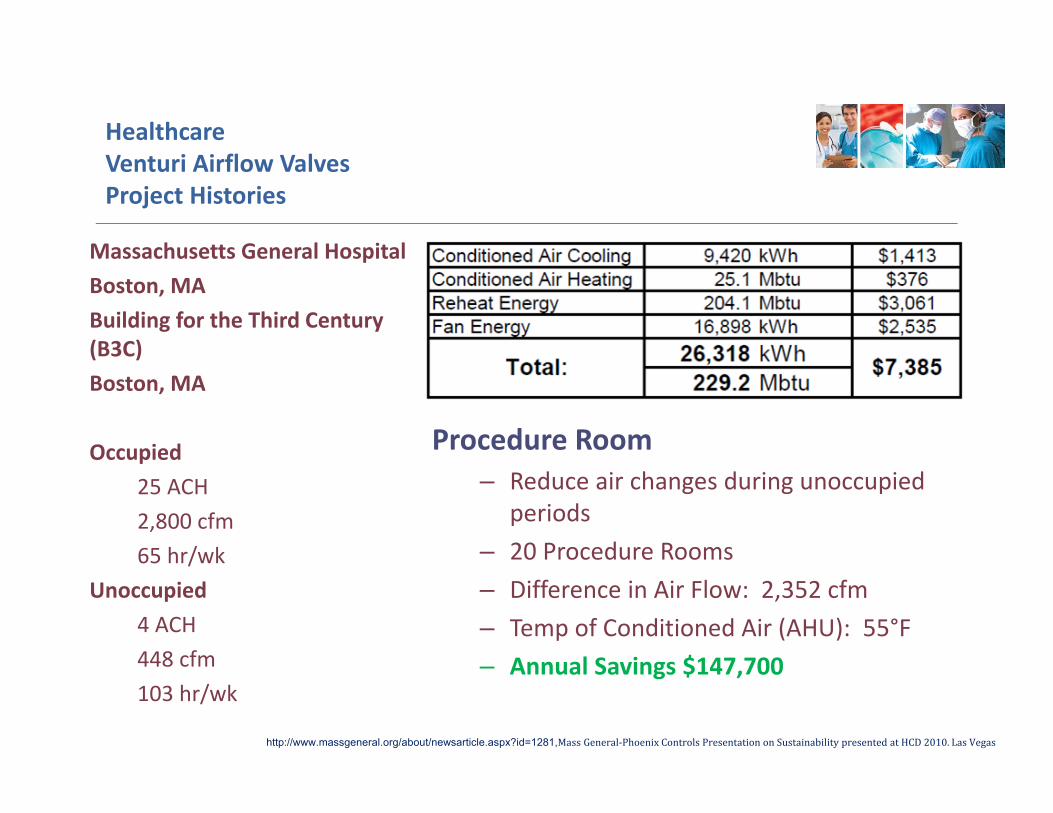
HealthcareVenturi Airflow ValvesProject Histories
Procedure Room– Reduce air changes during unoccupied
periods– 20 Procedure Rooms– Difference in Air Flow: 2,352 cfm– Temp of Conditioned Air (AHU): 55°F– Annual Savings $147,700
Massachusetts General Hospital Boston, MABuilding for the Third Century (B3C)Boston, MA
Occupied25 ACH2,800 cfm65 hr/wk
Unoccupied4 ACH448 cfm103 hr/wk
http://www.massgeneral.org/about/newsarticle.aspx?id=1281,MassGeneral‐PhoenixControlsPresentationonSustainabilitypresentedatHCD2010.LasVegas
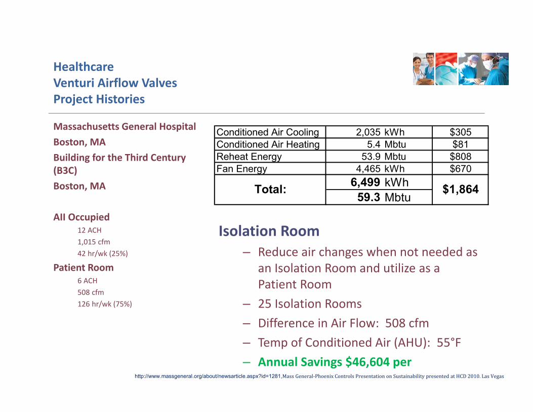
HealthcareVenturi Airflow Valves Project Histories
Isolation Room– Reduce air changes when not needed as
an Isolation Room and utilize as a Patient Room
– 25 Isolation Rooms – Difference in Air Flow: 508 cfm– Temp of Conditioned Air (AHU): 55°F– Annual Savings $46,604 per
Massachusetts General Hospital Boston, MABuilding for the Third Century (B3C)Boston, MA
AII Occupied12 ACH1,015 cfm42 hr/wk (25%)
Patient Room6 ACH508 cfm126 hr/wk (75%)
http://www.massgeneral.org/about/newsarticle.aspx?id=1281,MassGeneral‐PhoenixControlsPresentationonSustainabilitypresentedatHCD2010.LasVegas
Conditioned Air Cooling 2,035 kWh $305Conditioned Air Heating 5.4 Mbtu $81Reheat Energy 53.9 Mbtu $808Fan Energy 4,465 kWh $670
6,499 kWh59.3 Mbtu
$1,864Total:
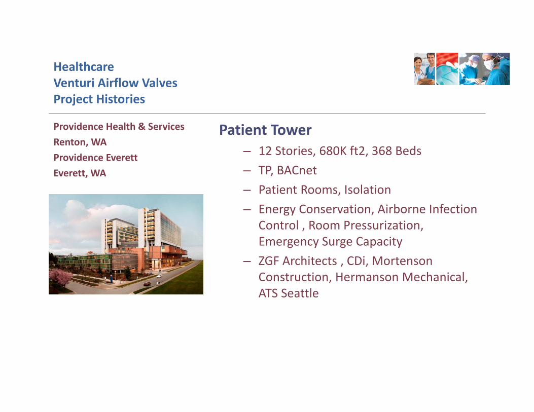
HealthcareVenturi Airflow Valves Project Histories
Patient Tower– 12 Stories, 680K ft2, 368 Beds– TP, BACnet– Patient Rooms, Isolation– Energy Conservation, Airborne Infection
Control , Room Pressurization, Emergency Surge Capacity
– ZGF Architects , CDi, Mortenson Construction, Hermanson Mechanical, ATS Seattle
Providence Health & Services Renton, WAProvidence EverettEverett, WA
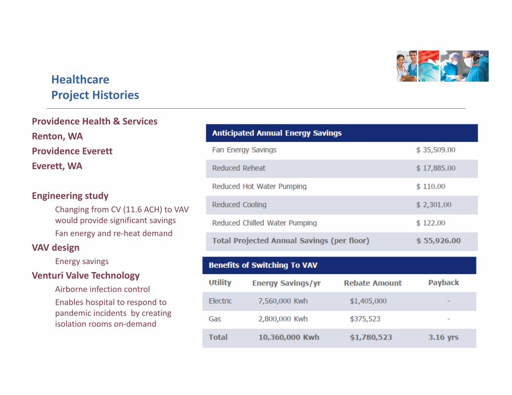
Healthcare Project Histories
Providence Health & Services Renton, WAProvidence EverettEverett, WA
Engineering study Changing from CV (11.6 ACH) to VAV would provide significant savings Fan energy and re‐heat demand
VAV design Energy savings
Venturi Valve Technology Airborne infection control Enables hospital to respond to pandemic incidents by creating isolation rooms on‐demand
OPTIMIZER SOFTWARE
Presentation and Discussion
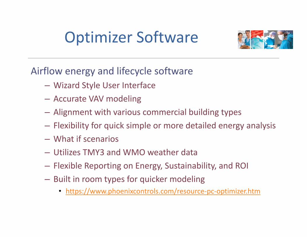
Optimizer Software
Airflow energy and lifecycle software– Wizard Style User Interface– Accurate VAV modeling – Alignment with various commercial building types – Flexibility for quick simple or more detailed energy analysis – What if scenarios – Utilizes TMY3 and WMO weather data – Flexible Reporting on Energy, Sustainability, and ROI – Built in room types for quicker modeling
• https://www.phoenixcontrols.com/resource‐pc‐optimizer.htm
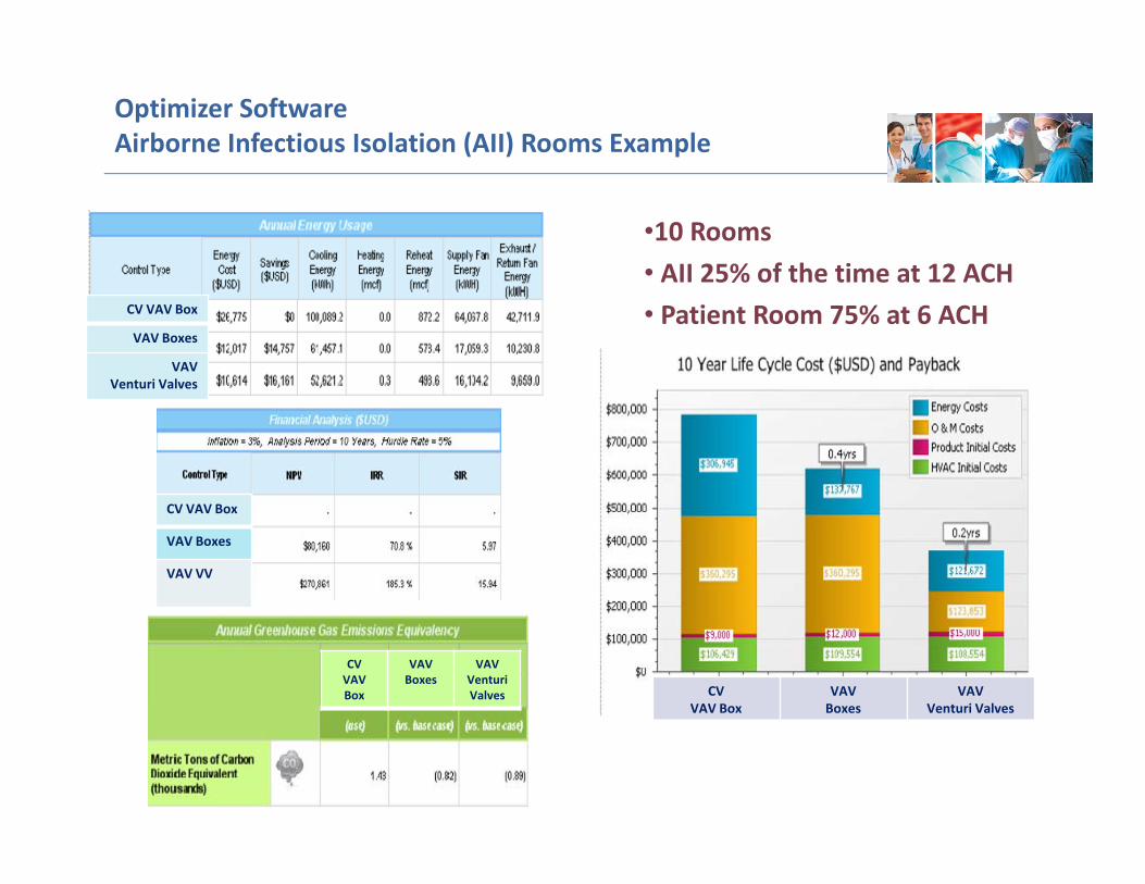
Optimizer SoftwareAirborne Infectious Isolation (AII) Rooms Example
•10 Rooms• AII 25% of the time at 12 ACH• Patient Room 75% at 6 ACHCV VAV Box
VAV Boxes
VAV Venturi Valves
CV VAV Box
VAV Boxes
VAV VV
CV VAV Box
VAV Boxes
VAV Venturi Valves CV
VAV BoxVAV Boxes
VAV Venturi Valves

SUMMARYPresentation and Discussion
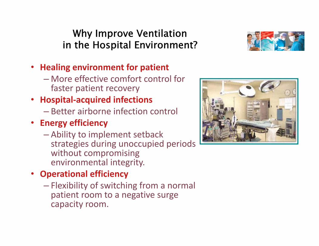
• Healing environment for patient– More effective comfort control for faster patient recovery
• Hospital‐acquired infections– Better airborne infection control
• Energy efficiency– Ability to implement setback strategies during unoccupied periods without compromising environmental integrity.
• Operational efficiency– Flexibility of switching from a normal patient room to a negative surge capacity room.
Why Improve Ventilation in the Hospital Environment?
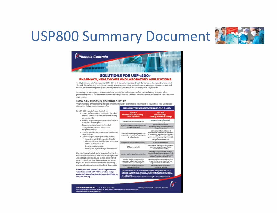
USP800 Summary Document

Healthcare Ventilation, “High Consequence Spaces”
Healthcare EnvironmentsMiSHE Chapter
Don MacDonald, Phoenix ControlsSeptember 28, 2017
Thank you!