head race tunnel melado hydropower plant, chilehead race tunnel melado hydropower plant, chile....
TRANSCRIPT

Head Race Tunnel Melado Hydropower Plant, ChileOptimization in Excavation and Rock Support
Cristobal Manquehual
Hydropower Development
Supervisor: Bjørn Nilsen, IGB
Department of Geology and Mineral Resources Engineering
Submission date: June 2012
Norwegian University of Science and Technology


NTNU Master Thesis
Page 1 de 416
ACKNOWLEDGMENT
I would like to express my sincere gratitude to my advisor Professor Bjørn Nielsen, for his wise guidance, patience and good will to answer all kind of geological inquiries at short notice.
I would like to express as well my sincere thanks to Professor Amund Bruland and his invaluable information and practical counseling in so many aspects related to tunneling.
It is highly appreciated for me the unselfish help provided by the PhD. Student Pawan Shrestha in aspects related to rock numerical modeling.
Sincere thanks go to the Chilean company Colbún which sponsored me during the whole master program and all the executives who trusted in me. Also, my gratitude to Sr. Engineer Matias Cespedes for all the information provided during the development of this thesis.
Finally, I want to thank the patience, the goodwill and effort provided by my wife who joined me in this adventure throughout these two years.
Cristobal Manquehual
June, 2012.

NTNU Master Thesis
Page 2 de 416
EXECUTIVE SUMMARY
The present thesis is to focus on the two head race tunnels within the Melado HPP, Chile.
The upstream tunnel is called Castillo 7800 m long and the downstream tunnel is called Vallical 8800 m long.
The feasibility study of this project was carried in 2010. The resulting report from this study was used as a basis for this thesis. Along with all the background information obtained from the feasibility studies, there are some other sources gotten from field investigation tests carried out after the end of the feasibility report.
Based on all the information collected, a new rock mass classification was carried out, identifying all the geological stretches for both tunnels. This classification was undertaken according to the RMR system (Bieniawski, 1973) and the Q-system (NGI, 1974).
The support required for both tunnels was estimated mainly based on empirical rock support methods. Numerical model by means of software Phase 2 as well as ground behavior analysis were carried out to provide a better understanding of actual problems expected during excavation that are not always cover by the empirical methods.
Once there was a clear understating of the rock masses involved in both tunnels along with their corresponding rock support, some analysis related to the tunnels were performed to improve the economical benefit of the whole project.
The first economic analysis undertaken was the optimum cross section for Drill & Blast excavation method. A detail analysis that systematizes the cost and advance rate involved in the round cycle of the Drill & Blast excavation method and rock support was used. A thorough analysis of energy losses was also carried out as well, making a distinction between unlined, shotcrete lined and reinforced shotcrete ribs tunnel stretches. The existing cross section of 6.9 m horse shoe shape tunnel turned out to be very small. The new optimum cross section for Castillo tunnel was 8.7 m diameter and 9 m diameter for Vallical tunnel.
The second economic analysis was a tunnel alignment change in order to improve some blast design parameters in stretches where their tunnel axis orientation was close to predominant joint set. In any of the two tunnel stretches analyzed turned out to be economically convenient to extend the tunnel for this purpose, even though the safety factor for the crew was not included.
Also, the convenience of extra adits was carried out. In fact, the layout of the feasibility report included one extra adit for each tunnel in order to have an earlier tunnel completion. The findings suggest that these adits are not economically convenient as long as the project’s electromechanical equipments take 34 months from their manufacturing to their assembly on project cavern.

NTNU Master Thesis
Page 3 de 416
TABLE OF CONTENTS
1. INTRODUCTION 6
2. GENERAL PROJECT DESCRIPTION 6
2.1 Location 6
2.2 Access 7
2.3 Project Details 7
2.4 About Basin & Water Resources 10
3. GEOLOGY 13
3.1 General Geology & Topography 13
3.2 Lithology 18 3.2.1Trapa Trapa (Mtt) rock formation 18 3.2.2Granitic Intrusive (Mgd) 18 3.2.3Cola de Zorro (PPlcz) Rock Formation 18
3.3 Distribution 19
3.4 Intact Rock Properties 19 3.4.1Uniaxial Compressive Strength 19 3.4.2Elasticity Modulus 20
3.5 Joint Characteristics 20 3.5.1Roughness 20 3.5.2Alteration and filling 21 3.5.3Joint spacing & Openness 21
3.6 Jointing System & Orientation 21
3.7 Degree of jointing 27
3.8 Weakness Zones 42
3.9 Water Leakage 43
3.10 In situ Stress 43 3.10.1Stress situation prior to excavation: 43 3.10.2Stresses surrounding rock excavation 47
4. ROCK MASS CLASSIFICATION 48
4.1 Q-System 48 4.1.1Introduction 48 4.1.2Methodology 49
4.2 RMR System 54 4.2.1Introduction 54 4.2.2Methodologhy 54
4.3 Results: 56

NTNU Master Thesis
Page 4 de 416
4.3.1Trapa-Trapa Rock Formation: “Blocky Andesite” 56 4.3.2Trapa-Trapa Rock Formation: Massive Andesite 61 4.3.3Trapa-Trapa Rock Formation: Weakness/fault zones 63 4.3.4Granitic Intrusive: “Blocky Granite” 65 4.3.5Granitic Intrusive: Weakness/fault zones 68
4.4 Comparison & Discussion 70
5. ROCK MASS 77
5.1 Ground Behavior 77 5.1.1Introduction 77 5.1.2Methodology 77 5.1.3Results 79 5.1.4Comments & Discussion 80
5.2 Rock Mass Properties 81 5.2.1Modulus of Deformation 84 5.2.2Shear Strength of jointed rock mass 86
6. ROCK SUPPORT 89
6.1 Introduction 89
6.2 Empirical Method 92 6.2.1RMR 92 6.2.2Q-System 92 6.2.3Results: 93 6.2.4Complementary Information 95
6.3 Analytical Method: Numerical Modeling 96 6.3.1Introducion 96 6.3.2Theory: 96 6.3.3Case 1: Blocky Andesite – Chainage 3500 m 96 6.3.4Case 2: Weakness Zone: Andesite Chainage 6400: 105 6.3.5Comments about Numerical Modelling 113
7. OPTIMUM CROSS SECTION ANALYSIS 114
7.1 Introduction: 114
7.2 Theory: 114 7.2.1Drillability 114 7.2.2Blastability 116 7.2.3Drill Bit Lifetime: 119
7.3 Methodology 119 7.3.1Assumptions for Drill & Blast 120 7.3.2Excavation Cost 123 7.3.3Rock Support cost 132 7.3.4Advance rate 134 7.3.5Cost of Energy Losses 149
7.4 Economic Evaluation 162

NTNU Master Thesis
Page 5 de 416
7.5 Results 162 7.5.1Castillo Tunnel 162 7.5.2Vallical Tunnel 175
8. ALTERNATIVES 193
8.1 Convenience of tunnel alignment change 193 8.1.1Introduction: 193 8.1.2Methodology 193 8.1.3Case 1: Vallical Tunnel Chainage 10,000 – 17,320 m 195 8.1.4Case 2: Vallical Tunnel Chainage 17,400 – 18,500 m 201
8.2 Convenience of shotcrete lining in unlined tunnel stretchesError! Bookmark not defined.
8.3 Convenience of closed conduit water conveyanceError! Bookmark not defined.
8.4 Convenience of extra adits 204 8.4.1Castillo Adit 205 8.4.2Vallical Adit 216
8.5 Convenience of TBM 228
9. CONCLUSION 230
10. BIBLIOGRAPHY 232

NTNU Master Thesis
Page 6 de 416
1. INTRODUCTION
The head race tunnel is by far the most important item in the HPP Melado, accounting for 50% of the total project cost based on its feasibility report.
This thesis is to focus on the two head race tunnels within the Melado HPP, which together account 16.6 km out of 18.8 km head race long. A review of the design, excavation and support of the existing layout given by the feasibility report will be undertaken based on state of the art knowledge.
2. GENERAL PROJECT DESCRIPTION
2.1 Location
The Guaiquivilo-Melado project is located within the VII Maule Region, Chile. From Santiago, the Guaiquivilo-Melado project is around 300 km south in a straight line, but around 450 km through the existing roads.
The following picture shows the location of the VII Maule Region, its capital Talca and the
Figure 2-1: General location of project area
Chile, Maule Region50 100 km

NTNU Master Thesis
Page 7 de 416
2.2 Access
The access to the project site from Talca is trough the international route CH-115 eastbound until its km 90 where the route L-399-K must be taken turning right (south). Following the latter route for 30 km the road reaches the Melado river through the hillsides of the Vallical brook. The following picture illustrates the above track description from Talca.
Figure 2-2: Access road to the project
2.3 Project Details
The “Guaiquivilo-Melado” project is a complex of six hydropower projects, of which four are regulated by a dam projected upstream of them. Those four projects run parallel to either the Guaiquivilo River (Calabozos HPP & Lleuques HPP) or the Melado River (Catalinas HPP & Melado HPP). The sequence given is to downstream.
Along with those four, two other run of river hydropower projects are included in the complex located in Guaiquivilo’s tributaries. These are Cristales HPP & La Puente HPP.
The following picture shows a top view of the Guaiquivilo-Melado project.

NTNU Master Thesis
Page 8 de 416
Figure 2-3: Top view of the Guaiquivilo Melado Project.
Figure 2-4: A longitudinal profile of the Guaquivilo-Melado provided by Colbún S.A.

NTNU Master Thesis
Page 9 de 416
Melado hydropower project is therefore at the downstream end of the complex regulated partly by the Guaiquivilo dam.
The following table shows the salient features of each project at the end of their feasibility reports:
Table 2-1: Salient features Guaiquivilo – Melado complex
With regard to Melado HPP, it is important to point out that the design discharge is 100 m3/s and therefore, its two head race tunnels on analysis must be able to convey up to that discharge.
The following image shows the two tunnels involved in the Melado project.
Figure 2-5: Layout of the Melado HPP and its two head race tunnels (Castillo & Vallical).
CALABOZO LLEUQUES LOS CRISTALES LA PUENTE CATALINAS MELADO
Design Discharge qd m3/s 80 80 10 15 100 100
Net Head Hn m 99 108 41 234 145 125 Total
Installed Power Pins MW 71 78 4 31 131 108 421 Annual Average
Energy Generation E GWh 285 406 11 165 782 625 2 273

NTNU Master Thesis
Page 10 de 416
The existing layout of Melado HPP consists of:
- Off-stream intake (Taking water directly from upstream tail race canal Las Catalinas HPP)
- 1700 head race canal
- 7800 m long Head race Castillo Tunnel.
- 560 m canal (Crossing the Vallical brook).
- 8800 m long Head race Vallical Tunnel.
- Pressure shaft 120 m deep.
- Cavern (83.7 m long x 20.5 m wide x 33.27 m high)
- Tail race tunnel 125 m long.
Specifically about the two tunnels, both have a horseshoe shaped excavation and the cross section diameter is 6.9 m obtained from an economic analysis. The hydraulic conveyance has been determined as free surface, using at design discharge 73% of the total height.
2.4 About Basin & Water Resources
The Melado River is a tributary to the Maule river, coming from its southern bank. Melado Watershed at the joint with Maule River is around 2250 km2. The river runs mainly northbound. From its start at Del Dial Lake until its joint with La Puente River, it is called Guaiquivilo. Downstream that joint, it is called Melado.

NTNU Master Thesis
Page 11 de 416
Figure 2-6: Melado basin
The Melado HPP takes the water from the tailrace tunnel of the upstream hydropower project Catalinas. The hydrology behavior of the basin, and particularly the potential generation from the Melado HPP was determined in previous studies [7], where the resulting input discharges for generation in Melado HPP are shown below.
Figure 2-7: Usable water for turbine. Weekly data from 60/61 to 2005/06; Qd = 100 m3/s.
0.0
20.0
40.0
60.0
80.0
100.0
0% 20% 40% 60% 80% 100%
m3 /
s
Generation Flows Curve for Melado HPP

NTNU Master Thesis
Page 12 de 416
This information will be relevant for the energy losses calculation within the tunnel economic cross section.

NTNU Master Thesis
Page 13 de 416
3. GEOLOGY
3.1 General Geology & Topography
The general geology and topography for the Castillo tunnel is shown in the next image:
Figure 3-1: Top view of the general geology for Castillo tunnel.

NTNU Master Thesis
Page 14 de 416
Note that the Cola de Zorro rock formation does not cut the contours, suggesting that is almost horizontal.
The following figures show the longitudinal profile of Castillo tunnel:
Figure 3-2: Castillo tunnel longitudinal profile. Chainage 1700 – 3700 m.
Figure 3-3: Castillo tunnel longitudinal profile. Chainage 3700 – 5500.

NTNU Master Thesis
Page 15 de 416
Figure 3-4: Castillo tunnel longitudinal profile
It follows from the longitudinal profiles that the maximum overburden for Castillo tunnel is around 560 m at chainage 3500 m. Also, one can visualize that there are not sudden changes in tunnel overburden. The two depressions in ground surface above tunnel axis are two brooks, but both are higher than 150 m overburden.
The general geology and topography for the Vallical tunnel is shown in the next image:

NTNU Master Thesis
Page 16 de 416
Figure 3-5: Top view of the general geology for Castillo tunnel.
The following for images show the type of rock involved for the Vallical tunnel.

NTNU Master Thesis
Page 17 de 416
Figure 3-6: Vallical tunnel longitudinal profile Chainage 10,000 – 12,400 m.
Figure 3-7: Vallical tunnel longitudinal profile Chainage 12,500 – 15,100 m.
Figure 3-8: Vallical tunnel longitudinal profile Chainage 15,200 – 17,500 m.

NTNU Master Thesis
Page 18 de 416
Figure 3-9: Vallical longitudinal profile: 17,500 – 18,800 m
3.2 Lithology
3.2.1 Trapa Trapa (Mtt) rock formation
As it is described in the geology report [4], this rock formation is a sequence of Andesitic lava, volcano-clastic rocks and continental sediments. Includes Andesite, Basalt Andesite, Dacite calc-alkaline. Additionally Volcanic Breccias and Tuffs can be found.
The rock formation would have formed during the boundary between Miocene – Pliocene around 16.5 and 5.3 million years ago.
3.2.2 Granitic Intrusive (Mgd)
This unit intrudes the area where emplaces the downstream end of Vallical Tunnel, with discrete outcrops and abundant colluvial, also rich in granitic blocks recognized throughout the right side of the “Melado” valley.
Batholiths Melado: On the project site, there are intrusive bodies composed from granodioritic to tonalite composition with acid or basic facies.
All the granitic material located on the project area intrudes volcanic and volcano-clastic material, which belongs to Trapa -Trapa rock formation.
3.2.3 Cola de Zorro (PPlcz) Rock Formation
It is defined by a volcanic sequence of Andesite and Basalts, widespread and subhorizontal tectonic.
The rock formation is constituted essentially by Andesitic-basaltic lava and pyroclastic material of similar composition, along with frequent bench of agglomerates and Breccias.

NTNU Master Thesis
Page 19 de 416
Glacial and fluvial erosions have created sudden cliffs. Also this unit is affected by tectonic blocks due to a normal fault.
Stratigraphic correlations and radiometric data say that this rock formation is from Pliocene Superior – Pleistocene between 3.5 and 11 million years ago.
3.3 Distribution
The existing tunnel layout crosses the following rock formations:
Castillo Tunnel: 7800 m
1700-9500 (7800 m): Trapa Trapa Rock Formation (Bed rock from Andesitic-Basaltic lava).
Vallical Tunnel: 8800 m
10050 - 10350 (300 m) : Trapa-Trapa rock formation
10350 - 18850 (8500 m) : Granitic Intrusive
3.4 Intact Rock Properties
For practical reasons, it is necessary to quantify some mechanical properties of the rock that can not be carried out by knowing only the type of rock formation, but rather by the rock type. Threfore it is necessary to select one rock type that best represent each rock formation.Andesite is an igneous volcanic rock, of intermediate composition that best represents the Trapa-Trapa rock formation. Granite is an intrusive acid rock that is quite often found in Batholith Melado.
3.4.1 Uniaxial Compressive Strength
Is the most commonly used method for testing the mechanical character of the rocks. A piece of core is loaded axially from both ends until failure occurs without confinement.
Granite is a well known rock of being strong. The values provided in reference [8] with an average value of Uniaxial Compresive strength equal to 154 MPA (71 test of rock worlwide) is quite conservative compared to the literature in general like rock lab (Statistical commercial software) that suggests values higher than 250 MPA. But the first value is consistent with the geology report carried out during feasibility studies [4] where a value larger than 150 MPA was suggested. Therefore an UCS conservative value of 150 MPA will be considered.
With regard to Andesite, reference [5] includes one failure example (Slabbing) in underground opening excavated in Andesite located in El Teniente Mine, Chile. This mine lies about 200 km northern of Melado project area. A good predicted failure compared to

NTNU Master Thesis
Page 20 de 416
field measurements was achieved using an UCS of 150 MPA as an input parameter. This value is quite consistent with UCS value given by reference [8].
Reference [6] summarizes case histories of failure in tunnels, including the main parameters involved (Type of rock, UCS, stress situation, etc). Among those cases, there is one excavated in a “blocky Andesite” also from El Teniente Mine, where an UCS of 100 MPA was considered for failure analysis.
For similar volcanic rocks like basalt, rock lab software assigns a UCS value between 100 and 250 MPA.
For Andesite, a conservative value of 100 MPA will be adopted.
With regard to weakness zone, reference [8] provides some values depending on the degree of weathering. A UCS value of 2.5 MPA will be considered for all the weakness zones.
3.4.2 Elasticity Modulus
It is the gradient of the stress-strain curve during uniaxial testing.
Reference [8] collects some test results for some typical rock types from around the world. Specifically for the relevant rock types involved in the project, the results are given below:
Those values will be adopted for intact rock E-modulus.
3.5 Joint Characteristics
This chapter describes the system of mechanical discontinuities in the rock mass.
The most relevant joint characteristics are available in the geology report [4] along with core drilling loggings which are summarized in the following description:
3.5.1 Roughness
The roughness of joint walls is characterized by a large scale waviness (Planar / Undulating, stepped) and a small scale smoothness (Rough / smooth / slickensided).
Andesite: Intact rock sample
Eci GPA 31
Number of tests: 6
Granite: Intact rock sample
Eci GPA 48Number of tests: 71

NTNU Master Thesis
Page 21 de 416
The following description was obtained from field mapping [4], for the two main rock formation involved in the project:
Trapa Trapa: Joint walls are mainly with no waviness (planar) and a smooth surface.
Granitic Intrusive: Joint walls are planar with rough surface.
Even though in core drilling SCHM-9 done in the Trapa-Trapa rock formation is visualized a rough wall surface in most of the cracks, the feasibility report [4] described Trapa Trapa rock formation with smooth surface. The last opinion was kept here since it is possible that core drilling SCHM-9 does not represent fairly this rock formation.
3.5.2 Alteration and filling
From field mapping documented in the geology report [4] plus core drillings undertaken in the project area, it was possible to obtain relevant data about the joint walls and how they are filled.
Trapa – Trapa: Slightly weathered joint walls filled with clay and chlorite coating.
Granitic Intrusive: From fresh to slightly weathered joint walls. There is hard and fine coating materials in close walls.
3.5.3 Joint spacing & Openness
From field mapping carried out during the feasibility report a range of joint spacing values are given for each rock type.
Trapa – Trapa: 100 - 300 mm (Equally spaced for the three joint sets).
Granitic intrusive: 60 - 600 mm (Equally spaced for the three joint sets).
With regards to openness, close joints are described for both Granitic intrusive and Trapa Trapa rock formation based on field mapping during the feasibility studies. This qualitative description could be interpreted as 0.1 – 0.5 mm from Bieniawski’s classification.
3.6 Jointing System & Orientation
As reference [8] defines is the occurrence of joint sets forming the system or pattern of joints as well as amount or intensity of joints.
The main characteristic of the joints are described for each rock formation directly involved in the project area.
The geology report [4] provides information about the orientation of the main joint sets by means of two stereonets (spherical projection), one for each tunnel. From this information,

NTNU Master Thesis
Page 22 de 416
it was highlighted for each joint set the corresponding Fisher concentration zone, the Strike (Dashed line for each joint set), the Great Circle (continuous line) and the representative Pole.
Castillo stereonet
The average values for each joint set are given in the next table:
The report also complement this information with the following statement: “The Jointing system for the Castillo Tunnel is defined by three main joint sets perpendicular to each other”. But from the image it can be identified along with the three joint sets some random joints. For practical purposes, the rock involved in the Castillo tunnel (Trapa Trapa rock formation) will be considered on this report as three joint sets with random joints.
Vallical Stereonet (Only Granitic intrusive)
For the second tunnel (Mostly granitic intrusive rock), there is also a stereonet showing the orientation of joint sets for the batholith Melado:
Main Joint sets Castillo TunnelJoint Set Strike Dip Angle Dip Direction
1 N 27 E 81 N 297 E2 N 2 E 31 N 272 E3 N 81 E 81 N 351 E

NTNU Master Thesis
Page 23 de 416
In the feasibility report [4], as well as it states in the Castillo tunnel, it is said that there are three joint sets perpendicular to each other visualized from field mapping. However, in this case the third joint set could be interpreted as random joints that only have in common a gentle dip angle. But all these random joints were considered as one joint to be consistent with the description. According to the rock mass classification Q system, there is not much difference between “two joint sets plus random joints” and “three joint sets” as it will be shown later in chapter 4.
Main Joint sets Vallical TunnelJoint Set Strike Dip Angle Dip Direction
1 N 71 E 90 N 161 E2 N 39 W 70 N 51 E3 N 76 E 20 N 346 E

NTNU Master Thesis
Page 24 de 416
Figure 3-10: Tunnel axis along with stereonet: Chainage 1700 – 3700 m.

NTNU Master Thesis
Page 25 de 416
Figure 3-11: Tunnel axis along with stereonet: Chainage 4000 – 9500 m.

NTNU Master Thesis
Page 26 de 416
Figure 3-12: Tunnel axis along with stereonet: Chainage 10000 – 17400 m

NTNU Master Thesis
Page 27 de 416
Figure 3-13: Tunnel axis along with stereonet: Chainage 17400 – 18800 m
3.7 Degree of jointing
Several methods can be used to measure the density of joints in the rock mass. Since there is log data for 8 core drillings carried out for this project, RQD will be the main parameter used to determine the degree of jointing in the rock masses involved in the project.
RQD is one dimensional classification system for characterizing the degree of jointing in a core drilling. It is defined as core bits larger than 10 cm divided by the measured length.
3.7.1.1.1 Core Drillings
Seven core drillings are available in the project area. Three are related to Castillo Tunnel and four to Vallical tunnel. It is important to stand out that only four were carried out before the feasibility report. These are core drillings: SCHM 1, SCHM 2, SCHM 3 & SCHM 9.

NTNU Master Thesis
Page 28 de 416
Figure 3-14: Overview of Core Drilling Locations

NTNU Master Thesis
Page 29 de 416
Core drilling 5 (145.3 m deep): Medium grain Granite with chlorite, calcite and hematite veins. Low mafic inclusion. The deeper, the higher content of pirite.
Core Drilling: SCHM - 5 Ground Surface: 805.5 m.a.s.l.
Depth 100 m.a.s.l.m
20 40 60 80
804.5
795.5
785.5
775.5
765.5
755.5
1
10
20
30
40
50

NTNU Master Thesis
Page 30 de 416
Core Drilling: SCHM - 5 Ground Surface: 805.5 m.a.s.l.
Depth 100 m.a.s.l .m
There is no information for the range 64-65 m deep (Problem with % recovered)
51
60
70
80
90
100
20 40 60 80
754.5
745.5
735.5
725.5
715.5
705.5

NTNU Master Thesis
Page 31 de 416
Core Drilling: SCHM - 5 Ground Surface: 805.5 m.a.s.l.
Depth 100 m.a.s.l.m
660.5
704.5
695.5
685.5
675.5
665.5
101
110
120
130
140
145
20 40 60 80

NTNU Master Thesis
Page 32 de 416
Core drilling 7 (105 m deep): Medium grain Granite with calcite veins.
Core Drilling: SCHM - 7 Ground Surface: 885.07 m.a.s.l.
Depth 100 m.a.s.l.m
20 40 60 80
884.1
875.1
865.1
10
20
30 855.1
845.1
835.1
1
50
40

NTNU Master Thesis
Page 33 de 416
Core Drilling: SCHM - 7 Ground Surface: 885.1 m.a.s.l.
Depth 100 m.a.s.l.m
815.1
805.1
795.1
60
70
80
90
100
834.1
825.1
785.1
51
20 40 60 80
Core Drilling: SCHM - 7 Ground Surface: 885.07 m.a.s.l.
Depth 100 m.a.s.l.m
105
101 784.1
780.1
Core Disking identified
20 40 60 80

NTNU Master Thesis
Page 34 de 416
Figure 3-15: Core drilling SCHM-7 (83.7 – 94 m deep)
Core drilling 8 (105 m deep): 0 - 40.5 m deep is constituted by fragments of granite, granodiorite, volcanic breccia and andesite. 40.5 – 105 m deep is andesitic basalt.
Core Drilling: SCHM - 8 Ground Surface: 887.3 m.a.s.l.
Depth 100 m.a.s.l.m
20 40 60 80
1 886.3
857.3
847.3
837.3
40
50
30
10 877.3
20 867.3

NTNU Master Thesis
Page 35 de 416
Core Drilling: SCHM - 8 Ground Surface: 887.3 m.a.s.l.
Depth 10 20 30 40 50 60 70 80 90 100 m.a.s.l.m
90
100
836.3
827.3
817.3
51
60
70
80 807.3
797.3
787.3
Core Drilling: SCHM - 8 Ground Surface: 887.3 m.a.s.l.
Depth 10 20 30 40 50 60 70 80 90 100 m.a.s.l.m
782.3
101
105
786.3

NTNU Master Thesis
Page 36 de 416
Figure 3-16: Core drilling SCHM-8. 76.1 – 83.05 m.

NTNU Master Thesis
Page 37 de 416
Core drilling 9 (105 m deep): Andesitic lava.
Core Drilling: SCHM - 9 Ground Surface: 892.5 m.a.s.l.
Depth 100 m.a.s.l.m
891.5
10 882.5
20 872.5
30 862.5
40 852.5
50 842.5
20 40 60 80
1

NTNU Master Thesis
Page 38 de 416
Core Drilling: SCHM - 9 Ground Surface: 892.5 m.a.s.l.
Depth 10 20 30 40 50 60 70 80 90 100 m.a.s.l.m
From pictures with less resolution
90 802.5
100 792.5
51 841.5
60 832.5
70 822.5
80 812.5
Core Drilling: SCHM - 9 Ground Surface: 892.5 m.a.s.l.
Depth 10 20 30 40 50 60 70 80 90 100 m.a.s.l.m
101 791.5
105 787.5

NTNU Master Thesis
Page 39 de 416
Figure 3-17: Core drilling SCHM-9 (89.2 – 92.55 m deep)
Core drilling 3: Ancient Fluvial Deposit & Marginal Aluvial
Core Drilling: SCHM - 3 Ground Surface: 850.4 m.a.s.l.
Depth 100 m.a.s.l.m
20 40 60 80
1 849.4
10 840.4
20 830.4
30 820.4
40 810.4
50 800.4

NTNU Master Thesis
Page 40 de 416
Figure 3-18: Core drilling SCHM-3. 63.2 – 67.2 m deep.
Core Drilling: SCHM - 3 Ground Surface: 850.4 m.a.s.l.
Depth 10 20 30 40 50 60 70 80 90 100 m.a.s.l.m51 799.4
83 767.4
60 790.4
70 780.4
80 770.4

NTNU Master Thesis
Page 41 de 416
Core drilling 1 (40 m deep): Basic Intrusive. Andesitic composition.
Core Drilling: SCHM - 1 Ground Surface: 834 m.a.s.l.
Depth 100 m.a.s.l.m
There i s no information for the range 18-20 m deep (Problem with % recovered)
833
10 824
20 814
30 804
40 794
20 40 60 80
1

NTNU Master Thesis
Page 42 de 416
Core drilling 2 (40 m deep): Andesitic Lava (Trapa Trapa).
3.8 Weakness Zones
One can visualize from figures 3.1 and 3.5 that most of the inferred weakness/fault zones are almost perpendicular relatively to the tunnel axis. These zones are mostly related to steep and narrow brooks. Based on the arguments given above, one could tend to think that these zones will be short stretches for the tunnels. To be on the conservative side, each fault/weakness zone will be considered as 100 m long.
Unfortunately there is not a clear character of the weakness zones, but one could extrapolate from the weathering on the Trapa-Trapa rock formation which is a volcanic rock that contains clay coating, that these weakness zones could reach the tunnel 200 m below ground surface. There are cases documented where tuff layer in basalt and similar volcanic rocks has reached several 100 m below surface.
Core Drilling: SCHM - 2 Ground Surface: 834 m.a.s.l.
Depth 100 m.a.s.l.m
20 40 60 80
1 833
10 824
20 814
30 804
40 794

NTNU Master Thesis
Page 43 de 416
3.9 Water Leakage
Water leakage is the measure of quantity of water that is coming inside the tunnel in liter/minute. It has the great influence for stability of tunnel during construction and operation. In case the clay formed in the Trapa-Trapa rock formation has swelling properties, water ingress could cause severe problems.
In the case of the Batholith Melado rock formation, there could also be water ingress problems due to low overburden near fault zones. This is not a coincidence, because the design criterion during the feasibility studies was to avoid tunnel overburden below 50 m because of surface weathering. And this restriction along with the effort to reduce the tunnel length triggers that the tunnel bends are exactly below brooks where inferred weakness are placed.
The decision of 50 m as a minimum overburden is quite reasonable after visualizing the result of some core drillings where the first 40 m is only crushed rock.
3.10 In situ Stress
The stress situation is a relevant input in rock stability and is governed by a combination of gravitational, topographic, tectonic and residual stresses. Magnitude and direction of in situ stresses prior to excavation are very important, but they are only possible to know well by performing rock stress measurements like triaxial stress measurements by drill hole overcoring test or hydraulic fracturing test. Any of these tests have been carried out so far in the project site, but some approximations can be applied in order to have a first approach.
3.10.1 Stress situation prior to excavation:
The first step is to assume that vertical stress𝜎𝑍 is a result of gravity alone.
𝜎𝑍 = 𝛾 ∗ 𝑧
𝛾 = Specific gravity of the rock.
𝑧 = depth below surface (overburden height).
The specific gravity assigned for granite is 0.027 MPA/m and for Andesite is 0.029 MPA/m.
The second step is to find a value for horizontal stress. As a first approach, one can assume that the ratio between horizontal and vertical stress k follows a certain correlation with depth z. The following chart try to link these variables based on average horizontal and vertical stresses measured from around the world.

NTNU Master Thesis
Page 44 de 416
Figure 3-19: Variations of ratio of average horizontal to vertical stress with depth (From Hoek & Brown, 1980).
From the last chart, it is possible to conclude that the correlation between k and z has this general relation:
𝑘 = 𝑎𝑧
+ 𝑏 where 100 < a < 1500 ; 0.3 < b < 0.5
Tendency to core disking was found in several core drillings, suggesting a high k value. One evidence of core disking was found at 100 m deep in core drilling SCHM-7 (Batholith Melado: Granite) and another in core drilling SCHM-1 (Andesite) at 32 m deep. A k value equal to 3 at 100 m was adopted. A combination of a and b values that meet this restriction is when a = 270 and b = 0.3.
The equation for k is shown in the previous char in red. And the horizontal stress is: 𝜎𝐻 = 𝑘 ∗ 𝜎𝑧

NTNU Master Thesis
Page 45 de 416
Figure 3-20: Core drilling SCHM-7: 97-65 – 104.5 m deep.
Figure 3-21: Core drilling SCHM-1: 30 – 38 m.

NTNU Master Thesis
Page 46 de 416
The last step is to assume that there is no topography effect on stress direction and therefore the major principal stress 𝜎1 is either horizontal or vertical depending on the resulting magnitudes of them and the minor principal stress 𝜎3 is perpendicular to it.
With these three steps one can have an idea of the principal stress magnitudes.
The overburden along Castillo and Vallical tunnels varies mainly between 100 m and 600 m. In order to provide an idea of the stress situation along the tunnels, it will be estimated the maximum and minimal principal stresses for these extreme values.
For 100 m overburden, the stress situation for each rock type is given below:
It is important to highlight that based on the last results; at 100 m overburden the major principal stresses would be horizontal in both cases. It may not be the wholly true because topography effect should still be relevant and major principal stress should be parallel to ground surface. As long as the ground surface is flat, the last results are valid.
For 600 m overburden, the stress situation for each rock type is given below:
z 100 mϒ 0.027 MPA/mσV 2.7 MPA
k= σh /σV 3 σh 8.1 MPA
σ1 8.1 MPA
σ3 2.7 MPA
Stress Situation: Granite
z 100 mϒ 0.029 MPA/mσV 2.9 MPA
k= σh /σV 3 σh 8.7 MPA
σ1 8.7 MPA
σ3 2.9 MPA
Stress Situation: Andesite

NTNU Master Thesis
Page 47 de 416
It is important to mention that in this case the major principal stresses would be vertical instead of horizontal in both rock types. It is expected that at a higher depth underground vertical stress becomes larger than horizontal stress.
3.10.2 Stresses surrounding rock excavation
An underground excavation changes the initial stress condition. For circular opening and anisotropic stress condition, Kirsch’s equations can be used to obtain the maximum and minimum tangential stresses:
𝜎𝜃(𝑚𝑎𝑥) = 3 ∗ 𝜎1 − 𝜎3
𝜎𝜃(𝑚𝑖𝑛) = 3 ∗ 𝜎3 − 𝜎1
The maximum tangential stress will occur on tunnel contour parallel to major principal stress and minimal tangential stress will occur on tunnel contour parallel to minor principal stress.
Even though the planned tunnel is not circular, but rather it has a horse shoe tunnel shape, the latter equations provide good results as long as there are not sharp corners on tunnel contour.
z 600 mϒ 0.027 MPA/mσV 16.2 MPA
k= σh /σV 0.75 σh 12.2 MPA
σ1 16.2 MPA
σ3 12.2 MPA
Stress Situation: Granite
z 600 mϒ 0.029 MPA/mσV 17.4 MPA
k= σh /σV 0.75 σh 13.1 MPA
σ1 17.4 MPA
σ3 13.1 MPA
Stress Situation: Andesite

NTNU Master Thesis
Page 48 de 416
Finally, it will be estimated the ratio between the maximum tangential stress 𝜎𝜃(𝑚𝑎𝑥) and the rock mass strength 𝜎𝑐 which is an indicator of eventual stress-induced problem. The last parameter is given in chapter 3.4 for each rock type.
At this stage, without analyzing the ground behavior of each rock formation, it is not possible to judge fairly the last results, but one could say that in case there is blocky Andesite and blocky Granite and topographic effect is insignificant, there should not be large stress-induced problems taking into account the most unfavorable anisotropic stress conditions.
4. ROCK MASS CLASSIFICATION
4.1 Q-System
4.1.1 Introduction
σθ MAX 21.6 MPAσθ MIN 0.0 MPA
σc 150 MPA
σθ MAX / σc 0.14
100 m overburden: Granite
σθ MAX 23.2 MPAσθ MIN 0.0 MPA
σc 100 MPA
σθ MAX / σc 0.23
100 m overburden: Andesite
σθ MAX 36.5 MPAσθ MIN 20.3 MPA
σc 150 MPA
σθ MAX / σc 0.24
600 m overburden: Granite
σθ MAX 39.2 MPAσθ MIN 21.8 MPA
σc 100 MPA
σθ MAX / σc 0.39
600 m overburden: Andesite

NTNU Master Thesis
Page 49 de 416
The Q-system was developed by NGI in 1974. NGI defines the Q-method as a numerical description of the rock mass quality with respect to rock stability, and is also used for estimating required permanent rock support in tunnels and caverns. In this chapter, only the rock mass classification is carried out. The corresponding rock support is developed in chapter 6.
From 1974, new updates have been carried out in order to include modern tunnel support. This empirical method is now based on data from more than 1250 examples from existing tunnels around the world.
4.1.2 Methodology
The Q-value is obtained by the following equation:
Q =RQD
Jn∗
JrJa∗
JwSRF
RQD = Rock Quality Designation.
Jn = Joint set number
Jr = Joint set roughness (Roughness of the most unfavorable joint).
Ja = Joint alteration number (Degree of alteration or filling along the weakest joint).
Jw = Joint water reduction
SRF = Stress Reduction Factor
The quotient RQDJn
represents the block size of the rock mass.
The quotient JrJa
represents the inter-block shear strength.
The quotient JwSRF
represents the active stresses.
The rating for each input parameter is shown in the following six tables:

NTNU Master Thesis
Page 50 de 416
Table 4-1: Rating of RQD value in the Q-system
Table 4-2: Joint set number
Table 4-3: Joint roughness number
Jr (Joint roughnes number)
c) No rock-wall contact when shearedDiscontinous joints Jr =4 Zone containing clay minerals thick enough to prevent rock-Rough or Irregular, undulating 3 wall contactSmooth, undulating 2 Sandy, gravelly or crushed zone thick enough to prevent rock-Slickensided, undulating 1.5 wall contactRough or Irregular, planar 1.5 Notes:Smooth, planar 1Slickensided, planat 0.5 II) Jr = 0.5 can be used for planar, slickensided joints having linieations,
provided the lineations are oriented for minimum strength.
Jr = 1
1.0
I) Add 1.0 if the mean spacing of the relevant joint set is greater than3 m.
Note: I) Descriptions refer to small scale features,and intermediate scale features, in that order.
a) Rock-wall contactb) Rock-wall contact before 10 cm shear

NTNU Master Thesis
Page 51 de 416
Table 4-4: Joint alteration number.
Table 4-5: Joint wáter reduction factor.
Jw (Joint water reduction factor)
Dry excavations or minor inflow, i.e. < 5 l/min locally ρw < 1kg/cm2 Jw = 1Medium inflow or pressure, occasional outwash oj joint fillings 1-25 0.66Large inflow or high pressure in competent rock with unfilled joints 2.5 - 10 0.5Large inflow or high pressure, considerable outwash of joint fillings 2.5 - 10 0.3Exceptionally high inflow or water pressure at blasting, decaying with time > 10 0.2 - 0.1Exceptionally high inflow or water pressure continuing without noticeable decay > 10 0.1 - 0.05Note I) The last four factors are crude estimates, increase Jw if drainage measures are installedII) Special problems cause by ice formation are not considered.

NTNU Master Thesis
Page 52 de 416
Table 4-6: Stress reduction factor.
Based on the description undertaken in chapter 3, all the Q-system input parameters can be determined.
The following chart provides the rock class according to the Q-system when it is known the Q-value.

NTNU Master Thesis
Page 53 de 416
Figure 4-1: Updated Q-system Chart, NGI.
In order to obtain the Q-value in walls, the last chart can also be used, and the corresponding Q value is related to the roof Q-value in the following way:
QWALL = 5*QROOF if QROOF > 10
QWALL = 2.5*QROOF if 0.1 < QROOF < 10
QWALL = Q ROOF if QROOF < 0.1

NTNU Master Thesis
Page 54 de 416
4.2 RMR System
4.2.1 Introduction
Rock mass rating was also included to have a benchmark for comparison to the Q-system.
RMR classification system developed by Bieniawski in 1973 includes the following six parameters.
- Uniaxial compressive strength of intact rock material.
- Rock Quality Designation RQD
- Spacing of discontinuities
- Condition of discontinuities
- Groundwater conditions
- Orientation of discontinuities
4.2.2 Methodologhy
The rating of each variable is given below:

NTNU Master Thesis
Page 55 de 416
Table 4-7: RMR input parameters and their rating
Table 4-8: Rating adjustment for discontinuity orientation.

NTNU Master Thesis
Page 56 de 416
Table 4-9: Rock mass classed base on RMR.
In order to compare the results between the Q-system and the RMR system, the following equation will be used:
𝑄 = 𝑒(𝑅𝑀𝑅−44)/9 (Bieniawski, 1989)
4.3 Results:
In Trapa-Trapa rock formation (represented by Andesite) a distinction is made between Massive, Blocky and Weakness zones.
In Granitic intrusive rock formation (represented by granite) a distinction is made between blocky and weakness zone. (No massive granite is expected as it will be shown in chapter 6 related to ground behavior).
Since in the RMR system an explicit rating is considered for discontinuity orientation, two rock mass classifications are given for “Blocky Trapa-Trapa” (or “Blocky Andesite”) and Blocky Granitic Intrusive (Or “Blocky Granite”). These two discontinuity orientations are “fair” when the strike of the predominant joint set compared to the tunnel axis is less than 20 degrees apart) and “favorable”, when the strike of the predominant joint set is higher than 20 degrees apart with regard to the tunnel axis.
4.3.1 Trapa-Trapa Rock Formation: “Blocky Andesite”
The following rock mass classification belongs to the Castillo Tunnel crossing the Trapa- Trapa rock formation in between weakness zones.

NTNU Master Thesis
Page 57 de 416
The RMR system makes an explicit distinction for discontinuity orientation. Hence, two RMR classifications are given for “blocky Andesite” along the Castillo Tunnel, fair (Chainage 1850 - 3900) and favorable orientation for the rest of the Castillo tunnel in between weakness zones.
Input parameter Rating Comment
RQD 90 RQD (20 m average) at the level of the tunnel axis from core drilling SCHM-9
Jn 12 3 joint sets plus random joints
Jr 1.0 Smooth joint surface & No waviness (Planar)
Ja 4 Clay and Chlorite coating (Contact between joint walls)
Jw 1.0 Minor inflow q < 5 l/min excluding weakness zones
SRF 1.0In general Medium stress:
0.22 < σθ MAX/σc < 0.37 ; 6.2 < σc/σ1 < 12.2
QROOF 1.9 Class D (Poor)QWALL 4.7 Class C (Fair)
Q-System = Trapa - Trapa Rock Formation (Andesite) in Castillo Tunnel"Blocky Andesite"

NTNU Master Thesis
Page 58 de 416
A Classification parameters & their ratings
1 Strength of intact rock material 10 σc = 100 MPA
2 RQD 20 (RQD = 90) from core drilling SCHM - 9
3 Spacing of Discontinuities 8 100-300 mm
4.1 Length, Persistance 23-10 m (No information available;
Average value adopted)
4.2 Separation 40.1 - 1 mm
(Assumed from "close joint" description)
4.3 Roughness 1 Smooth
4.4 Infilling (Gouge) 2 Soft filling < 5 mm
4.5 Weathering 3 Moderately weathered
4 Condition of Discontinuities 12
5 Ground Water 10 Inflow 10 l/min
B Rating Adjustment for discontinuity orientations
Tunnel -5 Fair
RMR 55.0 Fair (RMR rating)
Q-value (From RMR) 3.4 Poor (Q-System)
RMR System = Trapa - Trapa Rock Formation (Andesite) in Castillo Tunnel (Fair orientation) "Blocky Andesite"

NTNU Master Thesis
Page 59 de 416
Trapa-Trapa is also found in Vallical tunnel, and the main difference compared to the “blocky Andesite” in Castillo tunnel is that core drilling SCHM-8 is considered instead of core drilling SCHM-9 and higher water inflow problems are expected due to low overburden.
A Classification parameters & their ratings
1 Strength of intact rock material 10 σc = 100 MPA
2 RQD 20 (RQD = 90) from core drilling SCHM - 9
3 Spacing of Discontinuities 8 100-300 mm
4.1 Length, Persistance 23-10 m (No information; Average value adopted)
4.2 Separation 40.1 - 1 mm
(Assumed from "close joint" description)
4.3 Roughness 1 Smooth
4.4 Infilling (Gouge) 2 Soft filling < 5 mm
4.5 Weathering 3 Moderately weathered
4 Condition of Discontinuities 12 Sum up from 4.1 to 4.5
5 Ground Water 10 Inflow 10 l/min
B Rating Adjustment for discontinuity orientations
Tunnel -2 Favourable
RMR 58.0 Fair (RMR rating)
Q (From RMR) 4.7 Fair (Q-System)
RMR System = Trapa - Trapa Rock Formation (Andesite) in Castillo Tunnel (Favourable orientation) "Blocky Andesite"

NTNU Master Thesis
Page 60 de 416
Input parameter Rating Comment
RQD 70 RQD (20 m average) at the level of the tunnel axis from core drilling SCHM-8
Jn 12 3 joint sets plus random joints
Jr 1.0 Smooth joint surface & No waviness (Planar)
Ja 4 Clay and Chlorite coating (Contact between joint walls)
Jw 0.66 Medium inflow predicted (Low overburden)
SRF 1.0In general Medium stress:
σθ MAX/σc = 0.22 ; σc/σ1 = 12.2
QROOF 1.0 Class D/E Between Poor and Extremely PoorQWALLS 2.4 Class D (Poor)
Trapa - Trapa Rock Formation (Andesite) in Vallical Tunnel

NTNU Master Thesis
Page 61 de 416
4.3.2 Trapa-Trapa Rock Formation: Massive Andesite
An exception in Trapa-Trapa rock mass classification in between weakness zones was made for the Chainage 7770 - 9400 m (Near the downstream end of Castillo tunnel), where the core drilling SCHM-9 carried out in the area showed very good results with an RQD between 90 and 100 for the deepest 45 m.
The following rock mass classification belongs to the Castillo Tunnel stretch just described:
A Classification parameters & their ratings
1 Strength of intact rock material 10 σc = 100 MPA
2 RQD 13 (RQD = 70) From Core drilling SCHM-8
3 Spacing of Discontinuities 8 100 - 300 mm
4.1 Length, Persistance 23-10 m (No information available;
Average value adopted)
4.2 Separation 40.1 - 1 mm
(Assumed from "close joint" description)
4.3 Roughness 1 Smooth
4.4 Infilling (Gouge) 2 Soft filling < 5 mm
4.5 Weathering 3 Moderately weathered
4 Condition of Discontinuities 12
5 Ground Water 7 Inflow 10-25 l/min
B Rating Adjustment for discontinuity orientations
Tunnel -2 Favourable
RMR 48.0 Fair (RMR rating)
Q (From RMR) 1.6 Poor (Q-System)
RMR System = Trapa - Trapa Rock Formation in Vallical Tunnel ( Chainage 10,100 - 10,300 m) " Blocky Andesite"

NTNU Master Thesis
Page 62 de 416
Input parameter Rating Comment
RQD 90 RQD average at the level of the tunnel axis from core drilling SCHM 9
Jn 1 No joint set
Jr 1.0 smooth joint surface & No waviness (Planar)
Ja 4 Clay and Chlorite coating (Contact between joint walls)
Jw 1.0 Minor inflow q < 5 l/min excluding weakness zones
SRF 1.0 Competent rock; Medium stress ; favourablestress conditions
QROOF 23 Classe B GoodQWALL 56 Class A Very Good
Q-System = Trapa - Trapa Rock Formation "Massive Andesite" : Chainage 7770 - 9400 m

NTNU Master Thesis
Page 63 de 416
4.3.3 Trapa-Trapa Rock Formation: Weakness/fault zones
All the fault/weakness zones found in Trapa-Trapa rock formation are represented by the following Q- system rock mass classification:
A Classification parameters & their ratings
1 Strength of intact rock material 10 σc = 100 MPA
2 RQD 20 (RQD = 90)
3 Spacing of Discontinuities 20 > 2 m
4.1 Length, Persistance 23-10 m (No information available; Average
value adopted)
4.2 Separation 40.1 - 1 mm (Assumed from "close joint"
description)
4.3 Roughness 1 Smooth
4.4 Infilling (Gouge) 2 Soft filling < 5 mm
4.5 Weathering 3 Moderately weathered
4 Condition of Discontinuities 12
5 Ground Water 10 Inflow 10 l/min
B Rating Adjustment for discontinuity orientations
Tunnel -2 Favourable
RMR 70.0
Q (From RMR) 18.0
RMR System = Trapa - Trapa Rock Formation (Andesite) in Castillo Tunnel "Massive Andesite" Chainage 7770 - 9400 m

NTNU Master Thesis
Page 64 de 416
Input parameter Rating Comment
RQD 10 From Core drilling SCHM-1
Jn 20 Crushed rock
Jr 1.0 Smooth joint surface & No waviness (Planar)
Ja 6 Clay coating & argilic alteration
Jw 0.3 Large inflow eventually (Volcanic rock)
SRF 10.0 weakness zones with clay
QROOF 0.003 Class G Exceptionally poorQWALL 0.003 Class G Exceptionally poor
Q-System = Weakness Zone: Trapa-Trapa (Andesite)

NTNU Master Thesis
Page 65 de 416
4.3.4 Granitic Intrusive: “Blocky Granite”
Granitic intrusive is only found in Vallical tunnel. The rock mass classification is given in the following three tables for this rock formation where no weakness zone is expected:
A Classification parameters & their ratings
1 Strength of intact rock material 1 σc = 3 MPA
2 RQD 5 (RQD = 10) From core drilling SCHM-1
3 Spacing of Discontinuities 5 < 60 mm
4.1 Length, Persistance 0 Crushed rock (Not related to length)
4.2 Separation 1 1 - 5 mm (Assumption of longer separationin
crushed rock compared to blocky Andesite)
4.3 Roughness 1 Smooth
4.4 Infilling (Gouge) 2 Soft filling < 5 mm
4.5 Weathering 1Highly weathered (Heavily fractured; clay
coating)
4 Condition of Discontinuities 4
5 Ground Water 4 Dripping (Volcanic rock)
B Rating Adjustment for discontinuity orientations
Tunnel -12 Very unfavourable
RMR 7.0 Very Poor (RMR Rating)
Q (From RMR) 0.02 Extremely Poor (Q-System)
RMR System = Trapa - Trapa Rock Formation (Andesite) Weakness/fault zones

NTNU Master Thesis
Page 66 de 416
The RMR discontinuity orientation triggers two different classifications for “blocky-granite”. Fair Andesite between Chainage 10,000 -15,000 m and 17400-18500 m and favorable orientation for the rest of Vallical tunnel where no weakness zone is expected.
Input parameter Rating Comment
RQD 80 RQD (20 m average) at the level of the tunnel axis from Core drilling number SCHM-7
Jn 9 3 joint sets
Jr 1.5 Planar surface, rough joint surface
Ja 2 Contact between joint walls; Clean joints;Slightly altered joint walls
Jw 1.0 Minor inflow q < 5 l/min
SRF 1.0In general Medium stress :
0.14 < σθ MAX/σc < 0.24 ; 9.3 < σc/σ1 < 18.5
QROOF 6.7 Class C (Fair)QWALL 16.7 Class B (Good)
Q-System = Granitic Intrusive Rock Formation (Granite) in Vallical Tunnel"Blocky Granite"

NTNU Master Thesis
Page 67 de 416
A Classification parameters & their ratings
1 Strength of intact rock material 12 σc = 150 MPA
2 RQD 17 (RQD = 80) From Core drilling SCHM-7
3 Spacing of Discontinuities 10 60 - 600 mm
4.1 Length, Persistance 23-10 m (No information available;
Average value adopted)
4.2 Separation 40.1 - 1 mm
(Assumed from "close joint"description)
4.3 Roughness 3 slightly rough
4.4 Infilling (Gouge) 4 Soft filling < 5 mm
4.5 Weathering 5 Slightly weathered
4 Condition of Discontinuities 18
5 Ground Water 10 < Inflow 10 l/min
B Rating Adjustment for discontinuity orientations
Tunnel -5 Fair
RMR 62.0 Good (RMR Rating)
Q (From RMR) 7.4 Fair (Q-system)
RMR System = Granitic Intrusive (Granite) in Vallical Tunnel ( Fair Orientation) "Blocky granite"

NTNU Master Thesis
Page 68 de 416
4.3.5 Granitic Intrusive: Weakness/fault zones
All the fault/weakness zones found in Granitic Intrusive rock formation are represented by the following Q- system rock mass classification:
A Classification parameters & their ratings
1 Strength of intact rock material 12 σc = 150 MPA
2 RQD 17 (RQD = 80) From Core drilling SCHM-7
3 Spacing of Discontinuities 10 60 - 600 mm
4.1 Length, Persistance 23-10 m (No information available;
Average value adopted)
4.2 Separation 40.1 - 1 mm
(Assumed from "close joint"description)
4.3 Roughness 3 slightly rough
4.4 Infilling (Gouge) 4 Soft filling < 5 mm
4.5 Weathering 5 Slightly weathered
4 Condition of Discontinuities 18
5 Ground Water 10 < Inflow 10 l/min
B Rating Adjustment for discontinuity orientations
Tunnel -2 Favorable
RMR 65.0 Good (RMR Rating)
Q (From RMR) 10.3 Good (Q-system)
RMR System = Granitic Intrusive (Granite) in Vallical Tunnel ( Favorable Orientation) "Blocky Granite"

NTNU Master Thesis
Page 69 de 416
Finally, it is also given the RMR rating for Granitic Intrusive weakness/fault zones:
Input parameter Rating Comment
RQD 10 First 10 m from core drillings SCHM 5 & 7
Jn 20 Crushed rock
Jr 1.5 rough joint surface & No waviness (Planar)
Ja 2Contact between joint walls; Clean joints, non softening minerals coating; clay free content
Jw 0.3 Large infloe eventually (Low overburden)
SRF 5.0 Weakness zone; Shear zone in competent rock(clay-free)
QROOF 0.02 Class F Extremely PoorQWALL 0.02 Class F Extremely Poor
Q-System = Weakness Zone: Granitic Intrusive

NTNU Master Thesis
Page 70 de 416
4.4 Comparison & Discussion
The following chart summarizes the main results in this chapter:
A Classification parameters & their ratings
1 Strength of intact rock material 1 σc = 3 MPA
2 RQD 5(RQD = 10) First 10 m from core drilling SCHM 5
& 7
3 Spacing of Discontinuities 5 < 60 mm
4.1 Length, Persistance 0 Crushed rock (Not related to length)
4.2 Separation 1 1 - 5 mm (Assumption of longer separation in crushed rock compared to blocky granite)
4.3 Roughness 3 Slightly rough
4.4 Infilling (Gouge) 4 Hard filling < 5 mm
4.5 Weathering 3 Moderately weathering
4 Condition of Discontinuities 11
5 Ground Water 4 Dripping (Low overburden ≈ 50 m)
B Rating Adjustment for discontinuity orientations
Tunnel -12 Very unfavourable
RMR 14.0
Q (From RMR) 0.04
RMR System = Granitic Intrusive (Granite) Weakness/fault zones

NTNU Master Thesis
Page 71 de 416
From the chart, it can be inferred the following:
1- RMR and Q rock classification systems are quite consistent with each other, having almost no difference in blocky and massive rock formations.
2- Blocky granite has a higher Q-Value than “Blocky Andesite”.
3- The larger differences between RMR and Q rock classification systems lie on weakness/fault zones, where Q-values from RMR system are higher.
With regard to point 1, one can add that in general, massive and blocky rocks are well described and classified by RMR, even it could be considered better than Q-system in one aspect which is that RMR is explicitly sensitive to discontinuity orientation. However, RMR has some parameters that are not intuitive for poor rock conditions (faults or weakness zones). Concepts like “persistence” depending on discontinuity length, “adjustment for discontinuity orientation” and “UCS of intact rock” included in the RMR system are not intuitive parameters for crushed rocks. Q-system provides a more general overview when one is rating a crushed rock, without requesting input parameters that are more appropriate in blocky and massive rocks.
With regard to point 2, it is possible to say that 2 “Blocky Granite” obtained a better Q-value compared to “Blocky Andesite” because of:
- The expected Uniaxial Compressive Strength UCS is higher.
- The joint walls are less weathered and with a higher surface roughness.
- The infilling material is harder (sandy) than in the case of “Blocky Andesite” where clay was found.
1.E-03
1.E-02
1.E-01
1.E+00
1.E+01
1.E+02
Blocky Andesite in Castillo
Tunnel
Blocky Andesite in Vallical Tunnel
Massive Andesite in
Castillo Tunnel
Blocky Granite in Vallical Tunel
Weakness/fault zone Andesite
Weakness/fault zone Granite
Q -
Valu
e
Comparison between Rock Mass Classification Systems
Direct QROOF - Value
Direct QWALLS - Value
From RMR Q-Value
From RMR Q-value (Favorable orientation)

NTNU Master Thesis
Page 72 de 416
- “Blocky Granite” does not have random joints along with the three joint sets.
Finally, point 3 leads to conclude that if Q-system is adopted, a more conservative decision is made. Therefore, Q-system rock mass classification will be used to classify the tunnels, but Q-values will be corrected by RMR system in cases where favorable orientation is expected and Q-system is not quantifying it. The correction factor for the preliminary Q-system value will be the quotient between the new and preliminary Q-value from the RMR system.
Based on this, the Q value adopted for Castillo tunnel is shown below:
Table 4-10: Final rock mass classification for Castillo tunnel.
And for Vallical tunnel, the rock mass classification per tunnel stretch is given below:
ChainageStretch Length
m
Main Rock type
RMR Q (RMR) Comment QROOFQROOF
ADOPTED
1700 - 1850 150 Andesite 7 0.02 Surface weathering 0.003 0.0031850 - 3900 2050 Andesite 55 3.4 Fair orientation - Poor/Fair Andesite 1.9 1.93900 - 4330 430 Andesite 58 4.7 Good Orientation - Poor/Fair Andesite 1.9 2.64330 - 4430 100 Andesite 7 0.02 Inferred fault zone around Las Mulas brook 0.003 0.0034430 - 5350 920 Andesite 58 4.7 Good Orientation - Poor/Fair Andesite 1.9 2.65350 - 5450 100 Andesite 7 0.02 Inferred fault zone around Las Yeguas brook 0.003 0.0035450 - 6380 930 Andesite 58 4.7 Good Orientation - Poor/Fair Andesite 1.9 2.66380 - 6480 100 Andesite 7 0.02 Inferred fault zone I from aerial photos 0.003 0.0036480 - 7670 1190 Andesite 58 4.7 Good Orientation - Poor/Fair Andesite 1.9 2.67670 - 7770 100 Andesite 7 0.02 Inferred fault zone II from aerial photos 0.003 0.0037770 - 9400 1630 Andesite 70 18.0 Good Orientation - Good Andesite 23 239400 - 9500 100 Andesite 7 0.02 Surface Weathering 0.003 0.003
7800
Castillo Tunnel: Rock Mass Classification

NTNU Master Thesis
Page 73 de 416
Table 4-11: Final rock mass classification for Vallical tunnel.
Putting together all the different geological stretches found in both tunnels Castillo & Vallical, the rock mass classification based on the Q-system is:
ChainageStretch Length
m
Main Rock type
RMR Q (RMR) Comment QROOFQROOF
ADOPTED
10000 - 10100 100 Andesite 7 0.02 Surface weathering & inferred fault zone III
0.003 0.003
10100 - 10300 200 Andesite 48 1.6 Good orientation - Blocky Andesite 1.0 1.010300 - 10350 50 Transition 7 0.02 Weakness zone - rock formation change 0.003 0.00310350 - 10850 500 Granite 62 7.4 Fair Orientation - Blocky Granite 6.7 6.710850 - 10950 100 Granite 14 0.04 Inferred fault zone IV 0.02 0.0210950 - 11300 350 Granite 62 7.4 Fair Orientation - Blocky Granite 6.7 6.711300 - 11400 100 Granite 14 0.04 Inferred fault zone V 0.02 0.0211400 - 12550 1150 Granite 62 7.4 Fair Orientation - Blocky Granite 6.7 6.712550 - 12650 100 Granite 14 0.04 Inferred fault zone VI 0.02 0.0212650 - 13000 350 Granite 62 7.4 Fair Orientation - Blocky Granite 6.7 6.713000 - 13100 100 Granite 14 0.04 Inferred fault zone VII 0.02 0.0213100 - 13400 300 Granite 62 7.4 Fair Orientation - Blocky Granite 6.7 6.713400 - 13500 100 Granite 14 0.04 Inferred fault zone VIII 0.02 0.0213500 - 14150 650 Granite 62 7.4 Fair Orientation - Blocky Granite 6.7 6.714150 - 14250 100 Granite 14 0.04 Inferred fault zone IX 0.02 0.0214250 - 14750 500 Granite 62 7.4 Fair Orientation - Blocky Granite 6.7 6.714750 - 14850 100 Granite 14 0.04 Inferred fault zone X 0.02 0.0214850 - 15350 500 Granite 62 10.3 Good orientation - Blocky Granite 6.7 9.315350 - 15450 100 Granite 14 0.04 Inferred fault zone XI 0.02 0.0215450 - 16550 1100 Granite 65 10.3 Good orientation - Blocky Granite 6.7 9.316550 - 16650 100 Granite 14 0.04 Inferred fault zone XII 0.02 0.0216650 - 17400 750 Granite 65 10.3 Fair Orientation - Blocky Granite 6.7 6.717400 - 17500 100 Granite 14 0.04 Inferred Fault zone XIII 0.02 0.0217500 - 18300 800 Granite 62 7.4 Fair Orientation - Blocky Granite 6.7 6.718300 - 18700 400 Granite 65 10.3 Good orientation - Blocky Granite 6.7 9.318700 - 18800 100 Granite 14 0.04 Surface weathering 0.02 0.02
8800
Vallical Tunnel: Rock Mass Classification

NTNU Master Thesis
Page 74 de 416
Table 4-12: Rock mass classification for both tunnels together.
Rock mas Classification Q-system
From roof descriptionStretch
mQROOF QWALLS
Exceptionally Poor 800 0.003 0.003Extremely Poor 1100 0.02 0.02Poor 200 1.0 2.4Poor 2970 1.9 4.7Poor 2550 2.6 6.5Fair 5100 6.7 16.7Fair 2250 9.3 23.3Good 1630 23 113
16600

NTNU Master Thesis
Page 75 de 416
Figure 4-2: Rock mass classification for Castillo tunnel.

NTNU Master Thesis
Page 76 de 416
Figure 4-3: Rock mass classification for Vallical tunnel.

NTNU Master Thesis
Page 77 de 416
5. ROCK MASS
5.1 Ground Behavior
5.1.1 Introduction
As continuous or discontinuous materials behave differently, it is important to determine which type the rock mass in question is. The same type of ground will behave differently for different sizes of opening compared to the size of the blocks. The “continuity factor” CF defined as the ratio between the tunnel diameter Dt and block diameter Db [8] provides an idea about the rock mass behavior.
CF < 5 means a massive rock where the rock properties dominate.
5 < CF < 100 means that the ground is discontinuous or blocky.
CF > 100 means that the rock is heavily jointed and the material behaves like a soil.
5.1.2 Methodology
Continuity Factor:
As it was said before, the continuity factor is the ratio between the tunnel diameter Dt and block diameter Db. The tunnel diameter obtained from an economic analysis during the feasibility studies is 6.9 m for both tunnels. This value will be kept for rock mass behavior analysis. The procedure to determine the block diameter is shown below:
Block diameter 𝐷𝑏
The equivalent block diameter can be obtained from the block volume 𝑉𝑏:
𝐷𝑏 = (𝑉𝑏)1/3
𝑉𝑏= Blok volume.
In turn, the block volume 𝑉𝑏 can be estimated by the Block Shape factor 𝛽 which quantifies the magnitude difference between the distinct joint set spacing values and the Volumetric Joint Count 𝐽𝑉 which is the number of joints in a rock mass volume of 1 m3.
𝑉𝑏 =𝛽
(𝐽𝑉)3
𝛽 = It is the block shape factor.
𝐽𝑉 = The volumetric joint count.

NTNU Master Thesis
Page 78 de 416
The block shape factor varies between 27 and above 1000, being the lowest value for equi-dimensional blocky rocks and the highest values for long and flat rocks.
The volumetric joint set 𝐽𝑉 can be estimated in several ways. Below, it will be shown how to estimate it from the Rock Quality Designation RQD and from joint spacing values:
𝑱𝑽 from RQD:
𝐽𝑉 = 35 −𝑅𝑄𝐷3.3
𝑱𝑽 from Joint Spacing:
There is a distinction between joint sets alone and joint sets plus random joints.
Joint sets without random joints:
𝐽𝑉 = �1𝑆𝑖
𝑛
𝑖
𝑆𝑖 = Spacing related to joint set 𝑖.
Joint sets with random joints:
𝐽𝑉 = �1𝑆𝑖
+𝑁5
𝑛
𝑖

NTNU Master Thesis
Page 79 de 416
𝑁 = Number of random joints.
5.1.3 Results
The following tables show the adopted values of input parameters and the corresponding results for rock masses in between weakness zones.
Variable Magnitude Unit CommentJoint Spacing Si 0.2 m 100 - 300 mm (Equally spaced)Volumetric Joint count Jv 15.2 From 3 joint sets with random jointsBlock shape factor β 30 Equi-dimensionalBlock Volume Vb 0.01 m3
Block Diameter Db 0.20 mTunnel diameter Dt 6.9 mContinuity factor CF 34 Blocky zone
Continuity factor CF for Andesite from Joint spacing calculations
Variable Magnitude Unit CommentRock Quality Designation RQD 70 From Core drilling SCHM - 8 at tunnel axisVolumetric Joint count Jv 11.7Block shape factor β 30 Equi-dimensionalBlock Volume Vb 0.02 m3
Block Diameter Db 0.27 mTunnel diameter Dt 6.9 mContinuity factor CF 26 Blocky Zone
Continuity factor CF for Andesite from RQD
Variable Magnitude Unit CommentJoint Spacing Si 0.33 m 60 - 600 mm (Equally spaced)Volumetric Joint count Jv 9.1 From 3 joint sets Block shape factor β 30 Equi-dimensionalBlock Volume Vb 0.04 m3
Block Diameter Db 0.34 mTunnel diameter Dt 6.9 mContinuity factor CF 20 Blocky zone
Continuity factor CF for Granite from Joint spacing calculations

NTNU Master Thesis
Page 80 de 416
5.1.4 Comments & Discussion
From the last four tables, it is possible to deduct that both rock masses would behave as blocky rocks since their Continuity factor are always between 5 and 100.
It is important to point out that the Continuity Factor of “Granitic Intrusive” rock formation (represented by granite), obtained from two different methods, is lower than the Trapa-Trapa rock formation (represented by Andesite), meaning that the first one is less jointed than the second one.
The next chart shows the main types of instability problem once it is known the Continuity Factor CF and the stress situation:
Variable Magnitude Unit CommentRock Quality Designation RQD 80 From Core drilling SCHM - 7 at tunnel axisVolumetric Joint count Jv 8.3Block shape factor β 30 Equi-dimensionalBlock Volume Vb 0.05 m3
Block Diameter Db 0.37 mTunnel diameter Dt 6.9 mContinuity factor CF 19 Blocky Zone
Continuity factor CF for Granite from RQD

NTNU Master Thesis
Page 81 de 416
Based on the calculations carried out in this chapter and taking into account the results in chapter 3.10 (related to in situ stress) where no high stress levels are expected in any of the tunnels, one can conclude that block fall is the most relevant instability problem in between weakness zones.
It is clear that the corresponding CF value for very poor rock mass conditions will be above 100 due to crushed rock. In the case of fault zones located in the Trapa-Trapa rock formation, problems with flowing ground could be possible.
5.2 Rock Mass Properties
The reduction in rock mass strength due to discontinuities must be quantified in order to have a good understanding of the rock mass behavior. The Geological Strength Index GSI is a useful system to know the reduction in rock mass strength and several important parameters related to the rock mass depend on it.
5.2.1 GSI
The degree of jointing and the surface condition of the discontinuities are the two input parameters for this system. The following chart shows how they are rating:

NTNU Master Thesis
Page 82 de 416
Figure 5-1: GSI Characterization of rock masses: Hoek & Marinos, 2000
Based on the description given in chapter 3, it is possible to classify the different rock masses involved in the project. With regard to the interlocking classification in GSI, it is possible to say that both Andesite (Trapa-Trapa rock formation) and Granite (Batholith Melado) in between weakness/fault zones are “blocky”. Related to surface condition one could make a difference, rating Granite as “Good” (rough joint surface, slightly altered) and Andesite as “Fair” (Smooth joint walls and altered surface with clay).

NTNU Master Thesis
Page 83 de 416
In weakness/fault zones, it is possible to say that both rock types could be classified as “disintegrated”. Finally, with regard to surface conditions in weakness zones, one could make a difference rating the Batholith Melado (granite) weakness zone as “Poor”(hard infilling) and Trapa-Trapa rock formation as “very poor” (clay coating).
Along with this qualitative classification of interlocking and surface conditions for each rock mass that gives a fixed rectangle in the GSI system, one can combine it with some empirical relations between the GSI system and information from the rock mass classification:
GSI = RMR – 5 RMR > 23 (Biewniawski, 1989)
GSI = 9*Ln(Q’) + 44 (Lien and Lunde)
Q’ is the Q value with SRF and JW equal to 1.
Variable Magnitude Comment
From Qualitative description in GSI system GSI 45 - 65Range for "Blocky" interlocking and "Fair" surface conditions
From value Q' 1.9 Q-system with SRF = 1 & Jw = 1GSI value from Q-System (SRF = 1 & Jw = 1) GSI 49.7Rock mass rating RMR 55.0 (Fair orientation)GSI value from RMR system GSI 50.0GSI adopted for "Blocky" and "Fair" Andesite GSI 50
"Blocky" and "Fair" Andesite (Trapa Trapa rock formation)
Variable Magnitude Comment
From Qualitative description in GSI system GSI 55 - 75 Range for "Blocky" interlocking and "Good" surface conditions
From value Q' 6.7 Q-system with SRF = 1 & Jw = 1GSI value from Q-System (SRF = 1 & Jw = 1) GSI 61.1Rock mass rating RMR 62.0 (Fair orientation)GSI value from RMR system GSI 57.0GSI adopted for "Blocky" and "Good" Granite GSI 60
"Blocky" and "Good" Granite (Batholith Melado rock formation)
Variable Magnitude Comment
From Qualitative description in GSI system GSI 5 - 20 Range for "Desintegrated" interlocking and "Very Poor" surface conditions
From value Q' 0.08 Q-system with SRF = 1 & Jw = 1GSI value from Q-System (SRF = 1 & Jw = 1) GSI 21.6GSI adopted for "Desintegrated" and "Very poor" Andesite GSI 20
"Desintegrated" and "Very Poor" Andesite (Trapa Trapa rock formation)

NTNU Master Thesis
Page 84 de 416
5.2.2 Modulus of Deformation
This parameter is very relevant for the mechanical behavior of rock mass. There is no in situ measured in the field with regard to deformation modulus. Nevertheless, some indirect methods based on statistical analysis and rock mass classification systems will be considered to quantify this parameter.
Em = 2 ∗ RMR − 100 (RMR > 50) Bieniawski, 1978
Em = 10(RMR−10)/40 (RMR < 50) Serafim & Pereira, 1983
𝐸𝑚 = 25 ∗ 𝐿𝑂𝐺10(𝑄) (Q > 1) Grimsta & Barton, 1993
𝐸𝑚 = � 𝜎𝑐100
∗ 10(𝐺𝑆𝐼−10)/40 (𝜎𝑐 ≤ 100 𝑀𝑃𝐴) Hoek & Brown, 1998
𝐸𝑚 = 𝐸𝑐𝑖60∗ �𝜎𝑐𝑖 Phanti, 2006
Note that not always an equation will be used in order to respect the limited range of applicability.
The results for each rock type and rock mass conditions are given in the following 4 tables:
Variable Magnitude Comment
From Qualitative description in GSI system GSI 15 - 28 Range for "Desintegrated" interlocking and "Poor" surface conditions
From value Q' 0.38 Q-system with SRF = 1 & Jw = 1GSI value from Q-System (SRF = 1 & Jw = 1) GSI 35.2GSI adopted for "Desintegrated" and "Poor" Granite GSI 30
"Desintegrated" and "Poor" Granite (Batholith Melado)
GSI adopted for "Blocky" and "Fair" Andesite GSI 50GSI adopted for "Blocky" and "Good" Granite GSI 60GSI adopted for "Desintegrated" and "Very poor" Andesite
GSI 20
GSI adopted for "Desintegrated" and "Poor" Granite GSI 30
Summary of GSI Values adopted

NTNU Master Thesis
Page 85 de 416
Note that when the deformation modulus was obtained from the Q-system, the input value considered belongs to the roof Q-value only. When the RMR system was used, only fair orientation was considered, representing both fair and favorable discontinuity orientation. These assumptions are also valid for the following three tables.
Variable Magnitude Unit CommentElasticity modulus Ei 31 GPaUniaxial compressive stregth σci 100 MPADeformation Modulus (From σci) Em 5.2 GPa Panthi (Statistical)
Rock mass classification Q 1.9 Only QROOF consideredDeformation Modulus (From Q) Em 6.8 GPa Q > 1Rock mass rating RMR 55 Fair orientation Deformation Modulus (From RMR ) Em 10 GPa RMR > 50 equationGeological Strength Index GSI 50 "Blocky" & "Fair" Deformation modulus ( from σc ; GSI) Em 10 GPa σc < = 100 MPAValue adopted for Blocky Andesite Em 8.00 GPa Simple average (4)
"Blocky" Trapa-Trapa rock formation (Andesite)
Variable Magnitude Unit CommentElasticity modulus Ei 48 GPaUniaxial compressive stregth σci 150 MPADeformation Modulus (From σci) Em 9.8 GPa Panthi (Statistical)
Rock mass classification Q 6.7 Only QROOF consideredDeformation Modulus (From Q) Em 20.6 GPa Q > 1Rock mass rating RMR 62 Fair orientation Deformation Modulus (From RMR ) Em 24 GPa RMR > 50 equationValue adopted for Blocky Granite Em 18.1 GPa Simple average (3)
"Blocky" Batholith Melado rock formation (Granite)
Variable Magnitude Unit CommentRock mass rating RMR RMR 7 Deformation Modulus (From RMR ) Em 0.8 GPa RMR < 50 equationGeological Strength Index GSI 20 "Desintegrated" & "Very Poor" Deformation modulus ( from σc ; GSI) Em 2 GPa σc < = 100 MPAValue adopted for Weakness zoneAndesite
Em 1.3 GPa Simple average (2)
Weakness/fault zone Trapa-Trapa rock formation (Andesite)

NTNU Master Thesis
Page 86 de 416
5.2.3 Shear Strength of jointed rock mass
The strength of a jointed rock mass is a key parameter to predict the rock mass strength, especially in blocky or jointed rocks. Below, it will be shown the Hoek-Brown failure criterion along with all the rock mass parameters that it requires.
5.2.3.1 Generalized Hoek-Brown failure criterion
This failure criterion is:
𝜎1 = 𝜎3 + 𝜎𝑐 ∗ �𝑚𝑏 ∗𝜎3𝜎𝑐
+ 𝑠�𝑎
𝜎1 = Axial effective principal stress.
𝜎3 = Confining effective principle stress.
𝜎𝑐 = Uniaxial compressive strength of the rock mass.
S = Empirical constant analogous to the “cohesive strength” of the rock mass.
mb = Empirical constant analogous to the “friction angle” of the rock mass.
a = Empirical constant related to surface of the jointed rock and interlocking.
The three empirical parameters can be obtained from the GSI system, except the parameter mb that also requires a constant mi which is related to the intact rock. The equations are given below:
Variable Magnitude Unit CommentRock mass rating RMR RMR 14 Deformation Modulus (From RMR ) Em 1.3 GPa RMR < 50 equationValue adopted for Weakness zoneGranite
Em 1.3 GPa
Weakness/fault zone Batholith Melado rock formation (Granite)
Value adopted for Blocky Andesite Em 8.00 GPaValue adopted for Blocky Granite Em 18.1 GPaValue adopted for Weakness zoneAndesite
Em 1.3 GPa
Value adopted for Weakness zoneGranite
Em 1.3 GPa
Summary: Deformation Modulus for each rock type

NTNU Master Thesis
Page 87 de 416
𝑚𝑏 = 𝑚𝑖 ∗ exp �𝐺𝑆𝐼−10028
�
𝑠 = exp �𝐺𝑆𝐼 − 100
9�
a = 0.65 – 𝐺𝑆𝐼200
These three parameters are for the estimation of the peak strength parameters of jointed rock masses.
Finally, it is also necessary to know the residual Hoek-Brown parameters for the plastic behaviour of the rock mass.
𝑚𝑟 = 0.65 ∗ 𝑚𝑏 Ribacchi, 2000)
𝑠𝑟 = 0.04 ∗ 𝑠 (Ribacchi, 2000)
An analysis about the adopted values for mi will be undertaken first and then the results of the three empirical parameters for each rock type will be given:
The following table obtained from reference [5] shows the mi values for different igneous rocks, among them Granite and Andesite.
Hoek, 1983
And mi value of 33 is assigned for granite and a mi value of 19 is assigned for Andesite. In the case of granite, the value suggested is consistent with the value given by “Rock lab” data, (which comes along “Phase 2” commercial software). This software suggests for granite a mi equal to 32 ±3. In the case of Andesite, the same software suggests a value of

NTNU Master Thesis
Page 88 de 416
25 ± 5 which is a little higher than the value suggested from the last table. The values from the last table will be adopted for a conservative decision.
Andesite mi = 19
Granite mi = 33
GSI 50mi 19
mb 3.2s 0.0039a 0.4
mr 2.07sr 0.00015
"Blocky" Andesite Hoek-Brown Parameters
GSI 60mi 33
mb 7.9s 0.0117a 0.35
mr 5.14sr 0.00047
"Blocky" GraniteHoek-Brown Parameters
GSI 20mi 19
mb 1.1s 0.0001a 0.55
mr 0.71sr 0.00001
Weakness/fault zone Andesite

NTNU Master Thesis
Page 89 de 416
6. ROCK SUPPORT
6.1 Introduction
Rock support is provided to improve the stability in an underground opening. Rock support is determined by rock mass quality and external geological conditions but also by technology available and local past experience. The following description of different rock supports will try to include the most common supports used nowadays.
Scaling:
This is the process of taking out loose material in the tunnel contour immediately after blasting (and ventilation). This method is placed in this section because blocks can be scaled down instead of being held by rock support. This procedure can be done manually over the muck pile for small tunnels, but for the range of tunnel cross sections under analysis it is recommended mechanized scaling from Jumbo. The latter alternative is also safer for the crew during the drill and blast process.
Rock Bolting:
It transfers load from the unstable zone near the tunnel contour to the confined interior of the rock mass.
The most common bolts used for rock support are described below:
At the working face:
Mechanical anchor
The bolt is anchored by an expansion of it at the far end of the tunnel contour. On this end, the bolt has two wedge shaped steel blades and a conical nut so that tightening the bolt triggers an expansion against the drillhole wall.
Resin Anchor (Polyester cartridge)
GSI 30mi 33
mb 2.7s 0.0004a 0.5
mr 1.76sr 0.00002
Weakness/fault zone GraniteHoek-Brown Parameters

NTNU Master Thesis
Page 90 de 416
After the bolthole is done, two polyester cartridges are inserted to it up to the bottom. Thereafter, a rebar is put by rotating it which creates the mix and chemical reaction between the resin and the catalyst. Once it sets, the bolts are tensioned. It is possible to grout the rest of the hole against corrosion.
Behind the working face:
Untensioned grouted bolts (Dowels)
After the bolthole is done, the grouting is placed, filling up the hole before the bolt is inserted. This causes that bolts are surrounded by grout and therefore well protected against corrosion. Unlike the other bolt described, these are passive reinforcement elements that require some ground displacement to be activated.
Shotcrete:
This type of rock support is obtained by spraying concrete on the rock surface. It is usually combined with wire mesh (Mesh reinforced shotcrete) or steel fibers (Fibercrete which in both cases is to obtain a higher compressive strength and a higher ductility behavior (More energy absorption).
In areas of weakness zones heavy rock support will be considered as:
Lattice Girder:
As defined by the US Federal Highway Administration, Lattice Girder is a support made up of steel reinforcement bars laced together usually in a triangular pattern and rolled to match the shape of the opening. Lattice girder embedded in shotcrete can be an alternative to the concrete lining for extremely poor rock conditions.
Steel Arch:
It is formed by constructing rings made of rolled steel beams (There are different shapes) perpendicular to the tunnel axis. Steel ribs are often installed with shotcrete for the blocking (lagging) material.
Shotcrete Ribs:
Shotcrete reinforced ribs consist of steel rebar arches (Commonly 6 rebars of 16-20 mm diameter each one) anchored to the rock mass with radial bolts and 3 layers of shotcrete. As it is said in reference [8], the first layer of shotcrete, commonly between 100 to 150 mm, is put with steel fibers and before the rebars. The following two layers of unreinforced shotcrete which in total have a thickness of 150-300 mm are put after the rebars in order to cover them.

NTNU Master Thesis
Page 91 de 416
Pre-injection:
This method aims to improve stability by means of grouting ahead of the tunnel face before blasting. It suits for poor rock conditions and high water pressure.
Concrete Lining:
It is a full lining of the tunnel with concrete, establishing an arch capable to take considerable load. Reinforcement, anchorage and possibly concrete invert should be eventually included depending on the case. Cast in place concrete lining is implemented while excavating a tunnel through long weakness zones.
From the literature, there are documented experiences about some of the rock support described above and the convenience of one over another.
Related to Shotcrete:
- As it is said in reference [8] steel fiber shotcrete compared to wire mesh is being more and more common worldwide since it minimizes the labor intensive process of mesh installation.
- Wet mix shotcrete (Water is added before delivery into a positive displacement) has shown some advantages compared to dry mix method (Water is added to the mix at the nozzle) like higher production capacity, reducing rebound, improving work conditions, etc.
Related to heavy rock support:
There is consistency in the literature that lattice girders are easier and faster to install than steel arches. Lattice girder is considered [16] as an improvement of the steel arch being easier to manufacture, transport, storage mainly because it is lighter and more flexible.
On the other Hand, reference based on experience in Chile, [15] describes several advantages of shotcrete reinforced ribs over lattice girder like quicker to install, easier to repair (Add more shotcrete or add more steel rebars is not difficult in case it is required),

NTNU Master Thesis
Page 92 de 416
etc. The only hindrance visualized in the installation of the Shotcrete reinforced ribs in this project is the likely lack of crew’s experience that will affect the efficiency since it is not a well known solution in Chile for weakness zones.
Cast in place concrete lining will not be considered for the Melado Project because it is not expected long stretches of very poor rock conditions since all the identified weakness zones are almost perpendicular to the tunnel axis.
Pre-injection should be considered for the two weakness zones identified in the Trapa-Trapa rock formation (Andesite/Basalt/Breccia) since it is not uncommon to have significant water leakage through weakness zones located in these rock types.
All of these experience will be considered for the final assignment of rock support in each tunnel stretch.
6.2 Empirical Method
This is a statistical approach for assessing the stability of tunnels. The two best known rock support systems worldwide are covered here.
6.2.1 RMR
The empirical support estimation based on RMR system is given in the following table:
6.2.2 Q-System
The Q-system determines the temporary and permanent rock support required by two inputs value, the Q-value obtained from the rock classification system and the “Equivalent dimension” 𝐷𝑒 which weighs the purpose of the tunnel and the tunnel span.

NTNU Master Thesis
Page 93 de 416
𝐷𝑒 =𝐷𝑡𝐸𝑆𝑅
𝐷𝑡 = Diameter of the underground excavation.
𝐸𝑆𝑅 = Excavation support ratio = 1.6 for water tunnels.
The Q-System chart (was provided in Figure 4.1)
6.2.3 Results:
The estimated rock support RMR does not provide in detail the suitable rock support as Q does like rock bolt spacing, shotcrete rib spacing, shotcrete thickness, etc. Furthermore, the Q system is sensitive to the span (tunnel diameter) and the type of tunnel purpose (included in the Excavation Support Ratio ESR factor) which makes it a more valuable tool when one is analyzing different alternatives.
The Q System is chosen to select the support required to avoid instability problems, but RMR is not totally neglected, because it was indirectly included in the rock mass classification system by means of the correction factor of discontinuity orientation.
Using the Q-system chart, the rock support required for both tunnels Castillo and Vallical is given below:
Final rock support assigened by Q-system 6.9 m tunnel diameter (Both tunnels)
Rock Class(From QROOF)
Stretch m QROOF
Reinforcement Category in roof
QWALLS
Reinforcement Category in walls
Rock Support Summary: Roof & Walls
Exceptionally Poor
800 0.003 8 0.003 8 Reinforced Shotcrete ribs D40/4 c/c 1.2 m ; systematic bolting (Roof & Walls)
Extremely Poor
1100 0.02 8 0.02 8Reinforced Shotcrete ribs E35/5 c/c 2.3 m ;
systematic bolting (Roof & Walls)
Poor 200 1.0 5 2.4 4 7 cm Fibercrete in roof; 7 cm shotcrete in walls; systematic bolting (Roof & Walls)
Poor 2970 1.9 4 4.7 3 7 cm shotcrete in roof; Systematic bolting (Roof & Walls)
Poor 2550 2.6 4 6.5 1 7 cm shotcrete and bolts (both in roof only)
Fair 5100 6.7 1 16.7 1 Unsuppurted
Fair 2250 9.3 1 23.3 1 Unsuppurted
Good 1630 23 1 113 1 Unsuppurted
16,600

NTNU Master Thesis
Page 94 de 416
With regard to the weakness zones (the lowest two Q-values in the last chart) it is important to point out that:
D40/4 c/c 1.2 = 4 rebars in double layer in 40 cm thick lining with c/c spacing 1.2 m.
D35/5 c/c 2.3 = 5 rebars in double layer in 35 cm thick lining with c/c spacing 2.3 m.
Also, the Q-system chart specifies the radial bolt spacing input parameter depending on the Q-system value. All the relevant Q-system values for both Castillo and Vallical tunnels with the corresponding bolt spacing is summarized in the following chart:
QROOF
Radial Bolt spacing in shotcreted area
m
0.003 1.00.02 1.21.0 1.71.9 2.02.6 2.06.7 2.29.3 2.323 2.4

NTNU Master Thesis
Page 95 de 416
6.2.4 Complementary Information
Even though, the Q-system provides important information about the rock support to be assigned for instability problems, there are some details that must be complemented.
Radial bolt length:
In Norwegian tunnels the following expression is often used to find the bolt length
Lb = 1.4 + 0.184*Dt (m)
Dt = Tunnel diameter (m).
Lb (6.9 m tunnel diameter) = 2.67 m ≈ 3 m.
Rebar diameter:
When in the Q-system a certain stretch of a tunnel is in reinforcement category 8, it provides the number of rebars, but not the diameter of each one. Reference [8] suggests that rebars has a typical dimension of 20 mm diameter. This value is adopted for subsequent analysis.
Radial bolt diameter:
It will depend on the specific requirement in the tunnel and the type of bolt to be considered, but if a tunnel requires bolts with 20 tones ultimate tensile strength, the bolt should be around 25 mm diameter.
Concrete invert:
In general, invert in Norwegian water tunnels are not frequently concreted and only rough cleaning is carried out once the tunnel excavation has finished. Meanwhile, in Chile there is a certain tradition to have a concrete invert. A key difference between these countries is the cross section area in each place, where for several reasons (interest rate, tunnel total cost, energy price, etc), at a same discharge, in general tunnels in Chile are smaller and hence flow velocities higher (Flow velocity in tunnels above 2 m/s at design discharge is very often). The latter aspect can cause potential invert erosion problems in case it is left unlined and therefore invert is commonly concreted. This Chilean tradition has been kept in this thesis.

NTNU Master Thesis
Page 96 de 416
6.3 Analytical Method: Numerical Modeling
6.3.1 Introducion
The rock mass behavior, the stress situation and eventual tunnel inward deformation are handled more precisely in a numerical model analysis.
Phase 2 Software:
It is a 2D elasto-plastic finite element program for calculating stresses and displacements around underground openings.
Phase 2 uses a plane strain analysis where two principle in-situ stresses are in the plane of the excavation and no shear stresses and strains are out of plane.
Even though, it is ideally for continuous rock deformation analysis, the input parameters belong to the rock mass in order to quantify it fairly.
Two cases will be analyzed in order to identify eventually some problems that are not being visualized by the empirical methods.
6.3.2 Theory:
Some parameters must be explained before the cases are developed.
Dilation: It is a measure of the increase in volume of the material when sheared. When Hoek-Brown parameters are chosen, this input parameter varies between 0.33 mb for soft rock to 0.66 mb for hard rock.
Disturbance factor: It is related to the blast damage. It varies between 0 and 1, being the lowest value for an excavation carried out by TBM, and 1 for a very poor blast design tunneling.
6.3.3 Case 1: Blocky Andesite – Chainage 3500 m
6.3.3.1 Elastic analysis:
Elastic analysis is carried out first to check if rock support is required.
6.3.3.1.1 Input parameters:
The field stress considered here is the same as included in chapter 3.10. The way to put these values in Phase 2 software is shown in the next figure:

NTNU Master Thesis
Page 97 de 416
Figure 6-1: Field stress input parameters inserted in Phase 2.
The properties of the blocky Andesite were obtained in chapter 5.2. The way to include these parameters in Phase 2 is shown in the next figure:
Figure 6-2: Rock mass properties for blocky Andesite inserted in Phase 2.
6.3.3.1.2 Results:

NTNU Master Thesis
Page 98 de 416
The following picture shows the virgin stress situation before underground excavation is carried out:
Figure 6-3: In situ stress situation before excavation
It is visualized from the previous illustration that topographic effect is not that significant at 560 m of overburden measured from the tunnel roof, because the major principal stress is almost vertical and the minor principal stress is almost horizontal. The next picture shows in detail the stress situation before and after excavation.

NTNU Master Thesis
Page 99 de 416
Figure 6-4: Change in stress situation due to excavation
Before excavation After excavation
σ1 = 15.3 MPA σθMAX = 33 MPA
σ3 = 7.4 MPA σθMIN = 4 MPA
The maximum tangential stress takes place on the excavation boundary parallel to the major principal stress σ1. That is why the higher stresses after excavation occur on both side walls.
Finally it is shown the strength factor in order to visualize if rock support is required.
Figure 6-5: Strength factor for blocky Andesite in elastic anaysis.
As it can be seen from the last figure, there are some areas next to the walls where the strength factor is below one.
According to the Q-system, this tunnel should have systematic bolting in walls and roof and unreinforced shotcrete in roof. Below it will be checked if this rock support is enough to improve the tunnel stability. Also, a concrete slab in invert will be included.
6.3.3.2 Plastic Analysis:
Compared to the elastic analysis, some new input parameters are required like residual values for Hoek-Brown failure criterion and the input parameters of rock support:

NTNU Master Thesis
Page 100 de 416
6.3.3.2.1 Input parameters:
Figure 6-6: Rock mass parameters for blocky Andesite in plastic analysis.
Unreinforced shotcrete in roof:
The key input parameters for unreinforced shotcrete are given below:
Deformation Modulus: 30,000 MPA
Thickness: 7 cm.
Compressive strength: 25 MPA.
The way to include these parameters in software Phase 2 along with some others that are necessary is given below:

NTNU Master Thesis
Page 101 de 416
Figure 6-7: Unreinforced shotcrete input parameters:
Radial Bolts:
The key inputs for radial bolts from the Q-system and other complementary sources are summarized below:
Bolt length = 3 m.
Bolt diameter = 25 mm. (End anchored rock bolt was chosen with 20 tones of maximum strength and 25 % of pre-tensioning).
Square pattern installation: 2 m x 2 m.
The way to include these parameters in software Phase 2 is shown in the following two figures:
Figure 6-8: Radial bolt input parameters:

NTNU Master Thesis
Page 102 de 416
Figure 6-9: Radial bolt input parameters
6.3.3.2.2 Concrete Invert:
As it was said before, concrete invert is included only because of Chilean tradition. A thickness of 15 cm is considered.
6.3.3.2.3 Results:

NTNU Master Thesis
Page 103 de 416
Total displacement:
There is almost no difference in displacement between with and without rock support. In both cases the maximum displacement occurs at the middle of invert with a similar magnitude.
Sigma 1:
There is a slight difference near the invert caused by the concrete slab between without (left) and with support which increased the minimum tangential stress at the bottom. For the rest of tunnel contour there is no difference.

NTNU Master Thesis
Page 104 de 416
Strength factor:
There is no visible difference between with and without rock support.
Finally it is shown that not yielded support was found neither in bolts nor in shotcrete.

NTNU Master Thesis
Page 105 de 416
6.3.3.2.4 Comment about case 1:
At almost 600 m below surface, the topographic effect is not relevant.
It is difficult to visualize in a continuous rock model the support effect for tunnel excavation in rock of strong mass quality. The results above do not mean that rock support is not necessary; it just means that the instability problems in blocky rocks are not well predicted in a continuous rock model.
6.3.4 Case 2: Weakness Zone: Andesite Chainage 6400:
6.3.4.1 Elastic Analysis
Elastic analysis is carried out first to check if rock support is required.
6.3.4.1.1 Input parameters
The virgin stress distribution is considered exactly the same as this case.
The properties of the weakness zone in Trapa-Trapa rock formation (Andesite) were obtained in chapter 5.2. The way to include these parameters in Phase 2 is shown in the next figure:

NTNU Master Thesis
Page 106 de 416
6.3.4.1.2 Results:
The following picture shows the virgin stress situation before underground excavation is carried out:

NTNU Master Thesis
Page 107 de 416
From the last picture, one can visualize that there is still some topographic effect 350 m below surface. The next picture shows in detail the stress situation before and after excavation:
Before excavation (left image), the major principal stress σ1 is slightly tilted. The maximum tangential stresses after excavation are located in bottom right corner and upper left wall consistent with σ1.
Finally it is shown the strength factor in order to visualize if rock support is required.

NTNU Master Thesis
Page 108 de 416
The last figure clearly shows that rock support is required since along the whole tunnel contour the strength factor is below 1. The rock support suggested by the Q-system for this case is D40/4 c/c 1.2 and systematic bolting. Along with that rock support, a slab of 15 cm in invert is also included.
6.3.4.2 Plastic Analysis
6.3.4.2.1 Input parameters:
Shotcrete ribs:
The shotcrete ribs needed for this case is 4 rebars in double layer in 40 cm thick lining with c/c spacing 1.2 m. The systematic bolting is in a pattern of 1 m x 1 m. (Q-value = 0.003).
Lattice girder rock support was used instead of rebars reinforcement, since its application is easiest in software Phase 2, and the support behavior is similar. The input parameters inserted in software Phase 2 are shown in the following two figures:

NTNU Master Thesis
Page 109 de 416
Concrete Invert
The input values for concrete invert (15 cm slab thickness) are exactly the same as the first case “blocky” Andesite.

NTNU Master Thesis
Page 110 de 416
Radial Bolts:
The key inputs for radial bolts from the Q-system and other complementary sources are summarized below:
Bolt length = 3 m.
Bolt diameter = 25 mm. (End anchored rock bolt was chosen with 20 tones of maximum strength and 25 % of pre-tensioning).
Square pattern installation: 1 m x 1 m.
The way to include these parameters in software Phase 2 is shown in the following two figures:

NTNU Master Thesis
Page 111 de 416
6.3.4.2.2 Results:
Total displacement:
Exaggeration factor: 2
Displacement is strongly reduced from 40 cm in the case of unsupported tunnel invert to 8 cm.
Strength factor:
The zone of plastic yielding is significantly reduced by the rock support. The supported tunnel has only yield elements at the bottom where a slab of 15 cm was included.

NTNU Master Thesis
Page 112 de 416
Finally, it is shown that neither rock bolts nor shotcrete ribs (represented by lattice girder) are yielded.
6.3.4.2.3 Comments about case 2:

NTNU Master Thesis
Page 113 de 416
The cross section analyzed in Andesite fault zone clearly shows the need of heavy rock support. The shotcrete rib solution provided by the Q-system improves significantly the stability problem without having yielded elements. A warning is given for the invert, where even with a concrete slab there is a displacement of 8 cm that could crack it.
6.3.5 Comments about Numerical Modelling
Numerical model was used to visualize some aspects of the rock mass that are not predicted by empirical approaches.
At intermediate-seated underground opening and non steep hillsides as the two cases analyzed here (Underground excavation 350 & 560 m below surface), topographic effect is not that significant, finding that the major principal stress is almost vertical in both cases.
Also, case 2 showed that a thicker concrete invert could be required for weakness zones in Andesite where reinforced shotcrete ribs are suggested. An alternative would be a full concrete lining.

NTNU Master Thesis
Page 114 de 416
7. OPTIMUM CROSS SECTION ANALYSIS
7.1 Introduction:
A larger cross section will have a higher investment cost and a longer construction period but the hydraulic energy losses will be lower which increases the future incomes of the project. In contrast, a smaller cross section will trigger a lower investment cost and a shorter construction period but the hydraulic energy losses will be higher, reducing the future incomes of the project.
The existing diameter for both tunnels Castillo and Vallical is 6.9 m obtained from an economical analysis undertaken as part of the feasibility studies. This chapter aims to redo this study based on new geological information, new support estimation, new advance rate estimation and a thorough analysis of energy losses.
7.2 Theory:
Some input parameters used to quantify and standardize the excavation cost and advance rate are not always known outside Norway and they will be explained below.
7.2.1 Drillability
It is a measurement on how easy is to penetrate the rock for a certain drilling hammer. Drillability is governed by the capacity of the equipment and the character of the rock mass. Drilling rate index DRI is estimated by the Brittleness Value and the Sievers J-value.
The Brittleness Value is the percentage of the material that passes the 11.2 mm sieve after 20 drops of the 14 kg piston. The higher the brittleness value, the higher the DRI.

NTNU Master Thesis
Page 115 de 416
The Siever J-value SJ is the penetration measured in 1/10 mm after 200 rotations. The higher the SJ value, the higher the DRI.
The way DRI value is linked to the Siever J value and the brittleness value is shown below:

NTNU Master Thesis
Page 116 de 416
Drillability value calculated from the Brittleness Value S20 and the Sievers J- value SJ.
A DRI value of 49 will be considered for the cross section economic analysis in Andesite (Trapa- Trapa rock formation) and Granite (Melado Batholith). Drilling hammer AC COP 1838 was chosen.
7.2.2 Blastability
It is the amount of explosives needed to break the rock to a certain degree of fragmentation, where 50% of the blasted rock size is under 250 mm.
The rock blastability Index SPR is determined as follows:
𝑆𝑃𝑅 =0.736 ∗ 𝐼𝑎0.6 ∗ 𝐿𝑇0.7
𝑐1000
0.4∗ 𝑤𝑐
0.25∗ 𝜌2

NTNU Master Thesis
Page 117 de 416
C = Average dry sonic velocity between perpendicular and parallel to foliation m/s.
𝐼𝑎 = Dry sonic velocity ratio between parallel and perpendicular to foliation m/s.
𝜌 = Rock density g/cm3.
w = Detonation velocity of explosives m/s.
𝐿𝑇 = Charging density of explosives. (Amount of explosives per volume unit of Drillhole, g/cm3).
Blastability is influenced by:
Anisotropy (represented by 𝐼𝑎)
Density (represented by 𝜌)
Sonic velocity (represented by C).
Mineralogy and grain binding (Indirectly represented by C).
Charging density and explosives (Represented by LT)
Detonation velocity of the explosives (Represented by w).
The inputs w and LT depend on the type of explosives. If Emulsion is used its values are w = 4250 m/s; LT= 0.9 g/cm3.
Since there is not laboratory data, SPR value cannot be determined accurately, but Engineering Geological Laboratory at NTNU has collected data for different rock types as it is shown below:

NTNU Master Thesis
Page 118 de 416
SPR value tested in the Engineering Geological Laboratory at NTNU.
From the last chart, it is possible to visualize that both, the average SPR value for granite (representing the Batholith Melado) and for Basalt (Representing the Trapa – Trapa rock formation) are between medium and good blastability, but the index SPR does not take into consideration the variation of the rock mass fracturing and orientation of fractures which causes a reduction not quantified in blastability. Therefore, the same document suggests the reader to describe the blastability in a qualitative manner: Good, Medium and Poor blastability.

NTNU Master Thesis
Page 119 de 416
For the cross section economic analysis, poor blastability will be considered in weakness zones and medium blastability will be considered for both Granite and Andesite where fair and good rock mass conditions are expected.
When drillability and/or blastability are involved in the prognosis model of a variable, it is given its good and poor drillability and/or blastability. Medium values are computed by a simple average between the corresponding good and poor values.
7.2.3 Drill Bit Lifetime:
This variable tries to quantify the lifetime of the drill bit. The main input parameter is the hardness of the rock minerals which is related to the rock abrasiveness. Drill Bit Lifetime varies from 100 to 1800, representing very high steel wear to very low steel wear respectively. Quartz and plagioclase are among the most important minerals for a high wear bit, where the first one is expected to be found in significant percentage in the Batholith Melado and the second one in the Trapa-Trapa rock formation (represented by Andesite) . A drill bit lifetime of 200 has been assigned for both rock formations.
7.3 Methodology
A detail analysis that systematizes the cost and advance rate involved in the round cycle of the Drill & Blast excavation method was carried by Zare, Shokrollah (2007) PHd. thesis [11] & [12]. These reports are based on Norwegian tunneling experience and include recent advances in equipment and methods. These studies were taken in the absence of local prognosis models.
Related to rock support cost, the required support is based on the previous chapter and the unit price considered for each support method is taken from the Melado feasibility report (2010) which reflects the real rock support cost for this specific project.
With regard to rock support advance rate, the Department of Civil and Transport Engineering at NTNU provides a prognosis model [13] that was used in the absence of a local rock support prognosis model.
Finally, related to energy losses, the procedure applied is mainly the suggested by reference [14] approach on how to estimate the Manning roughness coefficient and the real cross section area in tunnels (Overbreak included). Some other sources are used to quantify the hydraulic effect of shotcrete lining [1] and shotcrete ribs [2].
The economic range of analysis is from 6.9 m (≈ A = 40 m2) to 9.3 m (≈ A = 69 m2) diameter for both tunnels to cover the optimum cross section for each tunnel.

NTNU Master Thesis
Page 120 de 416
Figure 7-1:Layout for optimum cross section
Note that there is no extra adit considered for this analysis.
7.3.1 Assumptions for Drill & Blast
Even though the Drill & Blast cost and advance rate documents cover a wider range of tunnel cross sections, some simplifications can be adopted related to the economic range of analysis between 40 and 69 m2.

NTNU Master Thesis
Page 121 de 416
Trackless transport: Only cross sections smaller than 16 m2 are recommended to be constructed with rail bound transport. Therefore for the whole range of cross sections analyzed, trackless transport will be chosen.
3 boom wheel mounted jumbo: A drilling jumbo with three drilling hammers is recommended for cross sections between 20 and 80 m2. This range covers the whole range of the current analysis.
Three boom tunneling rig: Picture obtained from Atlas Copco “Underground rock excavation”.
Scaling from drilling jumbo: Only tunnel cross sections smaller than 20 m2 should be scaled from muck pile with a crowbar. Larger cross sections, as the range under analysis here should be scaled from Jumbo.
No load and haul niches: These niches are recommended for cross sections smaller than 30 m2, which is lower than the minimum cross section under analysis here. Only turning niches will be considered between 40 and 65 m2 (each 300 meter), and no niches above that.
Some other criteria not recommended necessarily by the cost and/or advance rate prognosis model are adopted by different reasons which are given below:
Large-hole parallel cut: This type of cut is dominating in Norway [10]. The round length is not dependent on the tunnel cross section. It has a Good pull. It triggers less throw and spreading of the much pile, reducing the loading time. Finally it has a good fragmentation

NTNU Master Thesis
Page 122 de 416
Emulsion slurry as explosive: There is no restriction suggested by the cost or advance rate prognosis models about which kind of explosive should be used for tunnel cross sections larger than 16 m2 and both documents provide details for ANFO and Emulsion. However, both in the advance rate prognosis model in Drill and Blast and the PHd thesis “Conventional tunnel construction” 1997 [17] agree that emulsion is faster to install, it can deal with water leakage problems, requires less ventilation and causes less toxic gases than ANFO.
Charged Drillhole diameter = 48 mm: The cost and advance rate prognosis models provide information for both 48 mm and 64 mm. In general, a larger charged drill-hole triggers a better pull "𝑝𝑟" (efficiency ratio between effective round length and drilled length) [10], but also causes a higher overbreak [17]. The resulting economic convenience of either alternative is not clear and 48 mm was chosen arbitrarily.
Low skill level:
Number of empty holes Ng = 4 with a diameter = 102 mm each. The need of enough space for rock expansion that will be blasted is given at the beginning of the explosion by the cut. This empty area required to secure a full throw out depends on blastability and drilled length. For poor blastability and 5 m drilled length, [10] the blast design suggests 4 large holes with a diameter of 102 mm each. No difference was made for 3 m drilled length, where free space requirement should be less.
Blastability and drilled length will depend on rock mass conditions. In poor rock mass conditions where the degree of fracturing is very high, a poorer blastability is expected [10] . With regard to drilled length in the same rock conditions, the general rule is to reduce the drilled length (and consequently the round length) because of immediate rock support required as it is shown in the next illustration.
Figure 7-2: Reduced round length in poor rock conditions [8].

NTNU Master Thesis
Page 123 de 416
For this economic analysis, poor blastability and 3 m drilled length is adopted for extremely poor rock mass conditions which correspond to weakness/fault zones in either Trapa-Trapa rock formation or Batholith Melado. Meanwhile in fair and good rock mass conditions, in both Trapa-Trapa rock formation and Batholith Melado, medium blastability and 5 m drilled length is assigned.
Finally, some economic decisions are made to determine the cost and advance rate of each tunnel:
No extra adit is considered in tunnel layouts: This means that each tunnel (Castillo & Vallical) is excavated only from its two ends. The economic convenience of this decision will be demonstrated in the next chapter.
7.3.2 Excavation Cost
As it was said before, a statistical approach carried out by Zare, S. PHd thesis [12] will be used to estimate the excavation cost when Drill and Blast technique is used.
The cost in kroner is updated from 2005 to 2009, by an inflation of 10% among those years. Afterward a conversion rate of 6.19 between NOK and USD is used. The final conversion rate is 5.7.
Excavation cost in Drill and Blast technique comprises:
Drilling Costs
Charging (Explosive and detonator) Costs
Scaling Costs
Loading Costs
Hauling Costs
Tip Costs
Ventilation Costs
Electrical, Water Supply & Miscellaneous Costs
Labor Costs
Niche Costs
Unforeseen Costs
For this economic analysis, the excavation cost will vary due to:
Tunnel cross section area, which affects:

NTNU Master Thesis
Page 124 de 416
All the costs mentioned above, except Electrical & Water Supply.
Blastability, which affects:
Charging costs
Scaling costs
Drilled length lh which affects:
Charging Costs
Scaling costs
Labor costs
Tunnel length from one adit (Heading tunnel length) which affects:
Hauling Cost
Ventilation Cost
Electrical & Water supply Cost
Labor Cost
7.3.2.1 Drilling Cost:
7.3.2.2 Explosive costs:
0
100
200
300
400
500
600
30 40 50 60 70 80
USD 2
009/
m
Cross section m2
Total Drilling Cost cd
Poor drillabibity
Good Drillability

NTNU Master Thesis
Page 125 de 416
7.3.2.3 Scaling cost
0
50
100
150
200
250
300
350
30 40 50 60 70 80
USD
2009
/m
Cross section m2
Explosive Costs ce (Emulsion; 5% dynamite portion)
Poor Blastability
Good Blastability
0.95
1.00
1.05
1.10
1.15
1.20
3 3.5 4 4.5 5 5.5 6
k le
Drilled length lh
Drilled length correction for explosive costs

NTNU Master Thesis
Page 126 de 416
7.3.2.4 Loading cost
0102030405060708090
0 20 40 60 80 100 120 140
USD 2
009/
m
Cross section m2
Scaling Costs cs (From Drilling Jumbo)
Poor Blastability
Good Blastability
0.80.91.01.11.21.31.41.5
3 3.5 4 4.5 5 5.5 6
k ls
Drilled length lh
Drilled length correction for scaling costs

NTNU Master Thesis
Page 127 de 416
Volvo L – 330 (Recommended for cross section larger than 50 m2).
7.3.2.5 Hauling Cost:
The drop at 50 m2 is explained because of change in technology.
0
20
40
60
80
100
120
140
160
30 40 50 60 70 80
USD 2
009/
m
Cross section m2
Loading Costs cs (Loader for relevant cross sections)
Cat 966G - Truck
Volvo L330E - 35t dump truck
0
100
200
300
400
500
600
700
30 40 50 60 70 80
USD 2
009/
m
Hauling Cost ch (Full utilization of loader, horizontal adit)
1 km3 km5 km7 km

NTNU Master Thesis
Page 128 de 416
7.3.2.6 Tip Cost:
7.3.2.7 Ventilation Cost:
7.3.2.8 Electrical installation:
0
10
20
30
40
50
30 40 50 60 70 80
USD 2
009/
m
Cross section m2
Tip Cost ctip (Trackless Transport)
0
50
100
150
200
250
300
30 40 50 60 70 80
USD 2
009/
m
Cross section m2
Ventilation Cost cv
1 km
3 km
5 km
7 km

NTNU Master Thesis
Page 129 de 416
7.3.2.9 Water supply cost:
7.3.2.10 Miscellaneous:
0
5
10
15
20
25
30
1,000 2,000 3,000 4,000 5,000 6,000 7,000
USD 2
009/
m
Tunnel length m
Electrical Installations Cost cel
0
10
20
30
40
50
1 000 2 000 3 000 4 000 5 000 6 000 7 000
USD
2009
/m
Tunnel length m
Water supply Cost cw

NTNU Master Thesis
Page 130 de 416
7.3.2.11 Labour
10
15
20
25
30
35
40
30 40 50 60 70 80 90 100
USD 2
009/
m
Cross section m2
Miscellaneous Cost cm (Horizontal adit)
200
300
400
500
600
700
30 40 50 60 70 80
USD 2
009/
m
Cross section m2
Labour Cost cla (Without correction factors)

NTNU Master Thesis
Page 131 de 416
0.95
1.00
1.05
1.10
1.15
1.20
1.25
3.0 3.5 4.0 4.5 5.0 5.5 6.0
k la
Drilled length lh
Drilled length correction factor for labour
0.981.001.021.041.061.081.101.12
1,000 2,000 3,000 4,000 5,000 6,000 7,000
k la
Tunnel length L m
Tunnel length correction factor for labour
0
5
10
15
20
25
30
30 40 50 60 70
USD 2
009/
m
Cross section m2
Niches Cost cn (Turning niches)

NTNU Master Thesis
Page 132 de 416
Finally, the cost is updated from 2005 to 2009, by an inflation of 10% among those years. Afterward a conversion rate of 6.19 between NOK and USD is used. The final conversion rate is 5.7.
7.3.3 Rock Support cost
The rock support considered here will be related to what was carried out in the previous chapter. Some other complementary sources were considered when details are not provided. But only, the following rock support will be considered for the economic analysis:
Unreinforced Shotcrete
End anchored rock bolts
Dowells (grouted bolts)
Fibercrete
Reinforced shotcrete ribs (With rebars)
Concrete invert
Wire-Mesh for invert
The unit price of each item was obtained from the feasibility report in US dollar May, 2009.
These costs are the installed cost for the owner. This means direct cost and indirect costs like transport, installation and constructor company profit.
All the rock support included in the economic evaluation is mentioned below:
QROOF (0.003): Reinforced Shotcrete ribs D40/4 c/c 1.2 m; Systematic bolting (Roof & Walls)
QROOF (0.02): Reinforced Shotcrete ribs E35/5 c/c 2.3 m; Systematic bolting (Roof & Walls)
Fibrecrete USD/m3 985
Unreinforced Shotcrete USD/m3 895Rebars (20 mm diameter) USD/kg 4.8Bolts (25 mm, 3 m) galvanized end anchored USD/unit 70Bolts (32 mm, 6 m) fully grouted USD/unit 230
Concrete invert USD/m3 325
Wire mesh type ACM C-139 for invert USD/m2 8.8

NTNU Master Thesis
Page 133 de 416
Note that for the range of analysis between 6.9 m diameter and 9.3 m diameter which is related to the “Equivalent Dimension” De from 4.3 to 5.6 (Vertical axis in the Q-system) no change is visualized in reinforcement category. This is very important, because it means that the following table suits for the whole range of cross section areas:
Along with reinforced shotcrete ribs, Spiling bolts are always considered in weakness zones and are installed along with RRS Reinforced Shotcrete Ribs. Spiling bolt spacing is given by NFF Publication 19 with a range between 0.2 and 0.6 m. As it was said before, drilled length in weakness zones was set to 3 m, and with a pull of 91% (48 mm drill-hole diameter), the resulting round length is 2.73 m. The latter value is relevant when counting the number of spiling bolts per meter tunnel length. The adopted values for Spiling bolts are given below:
Either dowels or end-anchored bolts 25 mm diameter is adopted. The Dowel bolt cost is considered equal to end anchored bolt.
Rock bolts length of 3 m is considered for all the radial bolts as it was determined in the rock support chapter.
Fixed values for Shotcrete ribsShotcrete ribs Rebar (20 mm diameter) 2.5 kg/m/rebarNumber of rebars in Shotcrete Ribs (Q = 0.003) 4 UnitNumber of rebars in Shotcrete Ribs (Q = 0.02) 5 UnitSpacing Shotcrete Ribs RRS (Q = 0.003) 1.2 mSpacing Shotcrete Ribs RRS (Q = 0.02) 2.3 mFibrecrete thickness before shotcrete ribs (Q= 0.003 & Q = 0.02) 0.15 mUnreinforced shotcrete thickness to cover ribs (Q = 0.003) 0.25 mUnreinforced shotcrete thickness to cover ribs (Q = 0.02) 0.2 m
Fixed values for Spiling BoltsSpacing Spiling Bolts (6 m long, 32 mm diameter) 0.4 mRound length in poor rock mass conditions (3 m * 91%) 2.73 m
Fixed value for Radial boltsRadial bolt length (25 mm diameter) 3 m

NTNU Master Thesis
Page 134 de 416
7.3.4 Advance rate
The advance rate defines two important inputs which are the total length from each portal (heading length) and the tunnel construction period. The first input is a variable for the excavation cost influencing the Hauling Cost, Ventilation cost, Electrical cost, etc. The tunnel construction period is an input for the interest cost under construction that is also estimated for the economic analysis.
From the document Drill and Blast tunneling advance rate Shokrollah, Zare (2007) was predicted the advance rate for each geological stretch of the tunnel.
From reference [11]
This prognosis model considers four major operations in the round cycle:
I Drilling, Charging & Blasting
II Ventilation
III Loading and Hauling
IV Scaling and Rock Support
The operations I and III are divided in three categories:
1- Rig time = All unproductive operations regularly repeated from round to round like driving the drilling jumbo to and from the face.
2- Proportional Operation time = It is the productive time such as drilling (proportional to specific drilled meters), loading time (proportional to the amount of broken rock), etc.
3- Incidental lost time = It is the lost time that occurs randomly during tunnel operation like machine breakdown, delays because of shift change, etc.
All the rock support required at the tunnel face will be included within the round cycle. Support that can be carried out behind the face is not included in the round cycle.
7.3.4.1 Assumptions:
The effective working time per week = 120 hr.
One month for each portal construction period.
Advance rate of access roads to adits is 50 m/day
2/3 of the total estimated bolts were considered at the tunnel face and 1/3 behind the face for fair and good rock mass conditions, while all the bolts were considered at the face for weakness zones. This fact affects the advance rate, where the bolts installed at the tunnel face delays the excavation while the bolts installed behind the face don’t.

NTNU Master Thesis
Page 135 de 416
Fibercrete is installed always at the tunnel face. Unreinforced shotcrete is always installed behind the face.
All the heavy rock support estimated for poor rock conditions was considered at the tunnel face.
All the spiling bolts considered will be installed at the tunnel face.
As suggested by the document [11], fracture can lead to additional time consumption during drilling and up to 10% could be added because of this problem.
Some definitions used here in order to distinguish the different tunnel advance stretches (heading length) are explained below:
“Castillo 1” = Castillo tunnel stretch excavated from the Castillo brook portal.
“Castillo 2” = Castillo tunnel stretch excavated from Vallical brook portal.
“Vallical 1” = Vallical tunnel stretch excavated from Vallical brook.
“Vallical 2” = Vallical tunnel stretch excavated from its downstream end.
7.3.4.2 Drill and Blast:
I Drilling, Charging and Blasting
Rig Time:
Proportional Operation Time:
Drilling time
0
5
10
15
20
25
30 40 50 60 70 80
min
/rou
nd
Planned Cross section area A m2
Rig time Trb (Drilling, Charging & Blasting)
Use of drilling jumbo service platform

NTNU Master Thesis
Page 136 de 416
Drilling time: 𝑇ℎ + 𝑇𝑔 + 𝑇𝑓 + 𝑇𝐾 + 𝑇𝑠𝑎
𝑇ℎ= Drilling time for charged holes.
𝑇𝑔= Drilling time for empty holes.
𝑇𝑓= Time for moving drilling hammers.
𝑇𝐾 = Time for changing bit.
𝑇𝑠𝑎 = Lack of simultaneousness.
𝑇ℎ =𝑙ℎ ∗ 𝑁ℎ𝑣ℎ ∗ 𝑁𝑚
𝑙ℎ = Drilled length (3 m in weakness zone and 5 m in fair & good rock mass conditions).
𝑁ℎ = Number of charged holes.
𝑣ℎ= Net penetration rate for charged holes.
𝑁𝑚 = Number of drilling hammers = 3.
In the following chart the net penetration rate for the drilling hammer AC-COP 1838 is shown. Note that the net penetration rate is represented by vb instead of 𝑣ℎ as in the equation mentioned above. The difference between them is a correction factor in the penetration rate because of charged drillholes diameter khv, but this factor is 1 for 48 mm diameter and therefore vb and 𝑣ℎbecome the same value.

NTNU Master Thesis
Page 137 de 416
0
50
100
150
200
250
300
20 30 40 50 60 70
cm/m
in
Drilling rate index DRI
Net Penetration Rate vb (48 mm drillhole diameter)
AC-COP 1838
0
20
40
60
80
100
120
30 40 50 60 70 80
Num
ber o
f dril
lhol
es
Planned cross ection area Ap m2
Neccesary number of 48 mm drillholes Nh
Poor Blastability
Good Blastability

NTNU Master Thesis
Page 138 de 416
𝑇𝑔 =𝑙𝑔 ∗ 𝑁𝑔𝑣𝑔 ∗ 𝑁𝑚
∗ 1.25
𝑙𝑔 = Drilled length of large holes = 𝑙ℎ.
𝑁𝑔 = Number of large holes = 4.
𝑣𝑔 = Net penetration rate for empty holes.
𝑣𝑔= vb * khv
Values of the correction factor khv for drill-hole diameters different from 48 mm are shown in the next chart:
0.8
0.9
1.0
1.1
1.2
3 3.5 4 4.5 5 5.5
k bl
Drilled length lh m
Number of drillholes Correction factor for drilled length
Low skill level

NTNU Master Thesis
Page 139 de 416
𝑇𝑓 =𝑡𝑓 ∗ �𝑁ℎ + 2 ∗ 𝑁𝑔�
𝑁𝑚
𝑡𝑓 = Time for moving per hole.
Changing of Bits:
𝑇𝐾 =𝑙ℎ ∗ �𝑁ℎ + 2 ∗ 𝑁𝑔� ∗ 𝑓𝑘 ∗ 𝑡𝑘
𝑁𝑚
0%20%40%60%80%
100%120%140%160%
20 30 40 50 60 70 80 90 100 110 120Drillhole diamateter mm
Correction factor for penetration rate khv
0
0.2
0.4
0.6
0.8
1
3 3.5 4 4.5 5 5.5 6
min
/hol
e
Drilled length lh m
Time for moving tf per hole
Given
Extended

NTNU Master Thesis
Page 140 de 416
𝑡𝑘= Unit time for bit changing = 3 minutes.
𝑓𝑘 = Frequency of bit changing factor per drilled meter.
Next chart shows 𝑓𝑘 values depending on Drilled Bit Lifetime. Drilled bit lifetime equals to 200 has been adopted for both rock mass formations:
Lack of simultaneousness:
𝑇𝑠𝑎 = 𝑓𝑠𝑎 ∗ �𝑇ℎ + 𝑇𝑔 + 𝑇𝑓�
Charging time: kII * Tlb
0
0.05
0.1
0.15
0.2
0 500 1000 1500 2000 2500 3000
Chan
ge/d
m
Drilled bit lifetime
Frecuency of bit changing fk per drilled metre
0.00
0.04
0.08
0.12
0.16
30 40 50 60 70 80
f sa
Planned cross section area Ap m2
Factor for lack of simultanouesness fsa
3 hammers 150 cm/min
3 hammers 250 cm/min

NTNU Master Thesis
Page 141 de 416
kII = It is a correction factor for drilled length in charging time.
Tlb = Time determinant charging time without a correction factor.
The following chart shows Tlb values for emulsion and two charging lines as a function of different number of charged drillholes.
And the correction factor kII as a function of drilled length is shown below.
0.010.020.030.040.050.060.070.0
0 20 40 60 80 100 120 140 160
min
/rou
nd
Number of drill holes
Time-determinant charging time Tlb (Emulsion)
2 charging lines
0.8
0.9
1.0
1.1
1.2
3 3.5 4 4.5 5 5.5
k ll
Drilled length lh m
Charging time Correction factor for drilled length
Given
Extended

NTNU Master Thesis
Page 142 de 416
Note that the available information until 4 m drilled length was extended until 3 m drilled length in order to have a prognosis model for poor rock mass conditions, where the drilled length (and therefore the round length) is reduced.
Incidental Lost Time
Incidental lost time Ttb = 0.111*(operational Drilling + operational Charging + Rig time)
II Ventilation Break
III Loading and hauling:
Rig Time:
The rig time for Loading and hauling Trl is shown in the next table for the relevant cross sections in this economic analysis:
0
4
8
12
16
20
30 40 50 60 70 80
min
/rou
nd
Planned cross ection area Ap m2
Ventilation required for Emulsion explosives

NTNU Master Thesis
Page 143 de 416
Proportional Operational Time:
𝑇𝑙𝑡 =𝑉𝑟𝑄𝑙∗ 60
𝑉𝑟 = Rock volume which includes overbreak.
𝑄𝑙 = Normalized gross loading capacity.
𝑉𝑟 = 𝐴𝑝 ∗ 𝑙ℎ ∗ 𝑝𝑟 ∗ 𝑓𝑜
𝐴𝑝= Planned tunnel cross section area.
𝑝𝑟= Pull = 91% for 48 mm charged drill-hole diameter.
𝑓𝑜= Overbreak factor.
The following chart shows the overbreak factor as a function of cross section area.
10
14
18
22
30 40 50 60 70 80
min
/rou
nd
Planned cross ection area Ap m2
Rig time for loading and hauling Trl
Wheel loader + Trackless transport

NTNU Master Thesis
Page 144 de 416
Note that the overbreak factor includes niches only for cross sections smaller than 65 m2. It is important to point out that the overbreak factor here is for lauding and hauling purposes, taking into account the blasted cross section area with an invert being cleaned down and should not be confused with the overbreak considered for the hydraulic tunnel design which a lower overbreak is estimated as shown in the energy losses chapter (7.3.5).
The normalized gross loading capacity 𝑄𝑙 is shown for the relevant cross sections:
1.00
1.05
1.10
1.15
1.20
30 40 50 60 70 80
Fact
or o
f ove
rbre
ak f o
Planned cross ection area Ap m2
Factor of overbreak fo (For loading and hauling)
Overbreak excluding niches
Overbreak + Turning niches 300 m apart
0
50
100
150
200
250
300
30 40 50 60 70 80
asm
3 /h
Planned cross ection area Ap m2
Normalized gross loading capacity Ql (Wheel loader + Trackless transport)
Cat 966G - Truck
Volvo L 330E 35T Dump truck

NTNU Master Thesis
Page 145 de 416
The advance rate prognosis model [11], provides more alternatives in between the two chosen loading and hauling combinations, but for practical reasons only these two were selected. It is important to highlight that the chosen alternatives quantify the fact that the larger the cross section, the faster is the capacity of moving blasted rock due to a different bucket size, truck trailer size, etc.
Incidental Time:
The incidental time 𝑇𝑡𝑙 is estimated as follows:
𝑇𝑡𝑙 = 0.111 ∗ (𝑇𝑙𝑡 + 𝑇𝑟𝑙)
Scaling and Rock Support IV:
Scaling time: 𝑇𝑟 ∗ 𝐾𝑙𝑟
𝑇𝑟 = Scaling time per round without drilled length correction factor.
𝐾𝑙𝑟= Correction factor for drilled length in scaling time.
The following chart shows 𝑇𝑟 values for the relevant cross section area and blastability. Only scaling from jumbo was considered, because scaling from pile is not recommended for the tunnel sizes under the economic analysis:
0
20
40
60
80
100
30 40 50 60 70 80
min
/rou
nd
Planned cross ection area Ap m2
Scaling time per round Tr (From Jumbo & without drilled length correction)
Poor blastability
Good Blastability

NTNU Master Thesis
Page 146 de 416
Rock support:
0.8
0.9
1.0
1.1
1.2
3 3.5 4 4.5 5 5.5
k lr
Drilled length lh m
Correction factor for drilled length in scaling time
Given
Extended
0.98
1.00
1.02
1.04
1.06
1.08
1.10
1.12
1000 2000 3000 4000 5000 6000 7000
k le
Tunnel length m
Correction in advance rate by Tunnel length

NTNU Master Thesis
Page 147 de 416
0.000.050.100.150.200.250.300.350.400.450.50
0 4 8 12 16
hour
/m
Number of radial bolts / m
Radial bolts time
Installing bolts simultanously with the bolt hole drilling
0.0
1.0
2.0
3.0
4.0
5.0
6.0
7.0
8.0
0 20 40 60 80
hour
/rou
nd
Number of bolts per round
Spiling Bolts Installation time
2 machines

NTNU Master Thesis
Page 148 de 416
0.8
0.85
0.9
0.95
1
1.05
1.1
4 6 8 10 12
k
Spiling bolt length m
Correction factor for spiling bolt length
0.50
0.55
0.60
0.65
0.70
0.75
30 40 50 60 70 80
h/m
Planned cross section area Ap m2
Shotcrete ribs installation time

NTNU Master Thesis
Page 149 de 416
7.3.5 Cost of Energy Losses
The cost of energy losses along the project lifetime and updated to the plant commissioning is estimated as follows:
𝑬𝑳 =𝒈 ∗ 𝜼 ∗ 𝒒𝒅𝟑
𝑨𝒇𝟐 ∗ 𝑴𝟐 ∗ 𝑹𝒉𝟒/𝟑 ∗ 𝑻
′ ∗ 𝑷𝒆 ∗ 𝑫 𝑼𝑺𝑫/𝒎
𝑔 = Gravity force = 9.8 m/s2.
𝜂 = Global efficiency, including turbine, generator and transformer efficiencies = 90%.
0.05
0.10
0.15
0.20
0.25
40 50 60 70 80
h/m
3
Planned cross section area Ap m2
Fibrecrete installation time
5 cm shotcrete thickness
7 cm shotcrete thickness
10 cm shotcrete thickness
15 cm shotcrete thickness (Extrapolated)
0.6
0.8
1
1.2
1.4
1.6
1.8
2
0 5 10 15 20 25
k l
Correction factor for installation length of fibrecrete
Given
Extended

NTNU Master Thesis
Page 150 de 416
𝑞𝑑 = Power plant design discharge = 100 m3/s.
𝑀 = Manning roughness coefficient.
𝐴𝑓 = Hydraulic cross section area in m2.
𝑅ℎ = Hydraulic radius in m.
𝑇′ = Utilization time for head losses in hours.
𝑃𝑒= Long term Energy price = 0.065 USD/KWh.
𝐷 = Capitalization factor.
𝑇′ is estimated by the following equation:
𝑇′ = � �𝑞𝑞𝑑�3𝑑𝑡
𝑇
0
Graphically, it is the hatched area in the following chart:
𝑇′= 3681 hours.
The capitalization factor 𝐷 can be estimated as:
𝐷 =(1 + 𝑖)𝑛 − 1𝑖 ∗ (1 + 𝑖)𝑛
Where 𝑖 is the interest rate and 𝑛 is the project lifetime period. If one considers an annual interest rate of 10% with a project lifetime of 40 years, the capitalization factor is:
0.0
0.2
0.4
0.6
0.8
1.0
0 2000 4000 6000 8000 10000
(q/q
d)3
Hours in a year
Generation Flows Curve for Melado HPP

NTNU Master Thesis
Page 151 de 416
7.3.5.1 Manning Roughness Value & Hydraulic Cross Section Area
A thorough analysis is carried to estimate the energy losses in the two tunnels and particularly the Manning roughness coefficient value and the final hydraulic area for different tunnel stretches. These stretches are defined by the rock mass quality and their corresponding rock support required to improve stability which leads to different Manning roughness coefficient and hydraulic areas throughout the tunnel.
Particularly, hydraulic flow area and Manning roughness value will be obtained for unlined, shotcrete lining and shotcrete ribs tunnels, but this Manning roughness value is not the final one because it must be weighed with the concrete invert in all cases.
Einstein equation is used to estimate the equivalent Manning coefficient for the total cross section:
𝑀𝐺𝐿𝑂𝐵𝐴𝐿 =
⎝
⎜⎛ ∑𝑃𝑖∑ 𝑃𝑖𝑀𝑖3/2⎠
⎟⎞
2/3
𝑃𝑖 = Wetted perimeter with related to a Manning roughness 𝑀𝑖.
𝑀𝑖 = Manning roughness coefficient for the wetted perimeter 𝑃𝑖.
7.3.5.1.1 Unlined Tunnel
Manning Roughness Coefficient
The blast design plays a huge role in the Manning roughness coefficient when no rock support is required and the tunnel contour is left unlined. Among the most influential parameters that govern the resulting tunnel roughness after blasting are:
Rod length (Eccentricity).
Specific drilling (Drillhole spacing in contour)
Charging (Tunnel contour)
Annual Interest Rate i % 10%Economic life time n year 40
Capitalization factor D 9.78

NTNU Master Thesis
Page 152 de 416
The rod length has an important role in the Manning roughness coefficient. As it is said in reference [10], certain deviation at the bottom of contour drllholes (eccentricity) measured from the planned cross section is unavoidable since some space is required at tunnel boundary to drill these holes. The problem is illustrated in the following picture:
Image from PHd Thesis (Zare, S.) [12]: Drill & Blast Tunnelling
A longer rod length will lead to a higher eccentricity and the saw-toothed shape at blasted contour will be more marked. Therefore, the longer the rod length the rougher the contour. This conclusion was demonstrated in the Norwegian report “Head Losses in power plant tunnels” ( Falltap I Kraftverks Tunneler Rapport 1985):

NTNU Master Thesis
Page 153 de 416
Specific drilling has also an impact on contour roughness, particularly in Contour holes and Row Nearest Contour holes. The following chart shows a clear correlation between the contour hole spacing and Manning roughness coefficient for different cross sections:
Finally, charging also has an effect on Manning roughness, because if tunnel contour is heavily loaded, a considerable overbreak and a rough contour is achieved.
Even though, one could have a good correlation between each blasting design variable and the Manning roughness coefficient individually, it is not enough to estimate the resulting Manning roughness for a set of different chosen values in the blast design. But, in the same Norwegian report, it was given a classification of different classes, where a set of relevant variables are included with different specifications depending on the class type I, II or III. Class III was chosen for all the range of different cross sections included in the economic analysis which is the least demanding class alternative in terms of measures for improving contour roughness. The Manning roughness coefficient in unlined tunnels Mu for different tunnel cross section areas is given in the next chart for class III:

NTNU Master Thesis
Page 154 de 416
Class III Specifications:
Rod length: 18 feet (5.49 m).
Charging Pattern:
The next table summarizes the charging pattern for the drillholes depending on where they are located:
Drilling pattern:
Drillhole diameter = 48 mm
29
29.5
30
30.5
31
31.5
0 10 20 30 40 50 60 70 80
MU
Planned cross section area Ap m2
Manning Roughness Value for Class III
Invert Cut EasersRow
nearest contour
ContourCharging Pattern
Class 3
90% 90% 70% 70% 70%Charged length
(% of total drilled length)
100% 100% 100% 70% 40%Charging Density
(% of drilled area within charged length)

NTNU Master Thesis
Page 155 de 416
The burden and spacing values for the contour are given as intervals where the lowest value applies for a 20 m2 cross section and the highest one for 120 m2. It means that for a cross section of 70 m2 in good blastability condition, burden should be around 0.9 m and spacing should be around 0.85 m.
It is important to point out that the Manning roughness coefficient estimation undertaken below does not apply well in rocks with thin foliation or bedding and in cases of heavily fractured rock, but they are not the case for most of these two tunnels under analysis.
Hydraulic Area
The hydraulic design cross section area should include the overbreak for a fair economic evaluation, but not all the overbreak is used by the water for conveyance in unlined tunnels. Water is not able to follow sudden changes throughout the tunnel contour, and therefore the effective flow area is less than the total overbreak. The design hydraulic overbreak is estimated as 75 % of total overbreak [14]. The following chart shows for rough cleaning tunnel invert and class III blast design, the hydraulic overbreak:

NTNU Master Thesis
Page 156 de 416
The chart above is for rough cleaning invert and unlined walls and roof. As it was mentioned before, the invert will be concrete lined and therefore the resulting hydraulic area 𝐴𝑉_1 is reduced to:
𝐴𝑉_1 = 𝐾𝑜 ∗ 𝐴𝑝 − 𝑡𝐼𝑁𝑉𝐸𝑅𝑇 ∗ 𝐿𝐼𝑁𝑉𝐸𝑅𝑇
𝐴𝑝 = Planned cross section area.
𝑡𝐼𝑁𝑉𝐸𝑅𝑇 = Invert thickness equals to 30 cm = 15 cm concrete invert + 15 cm granular soil.
𝐿𝐼𝑁𝑉𝐸𝑅𝑇= Invert with.
𝐿𝐼𝑁𝑉𝐸𝑅𝑇 = 𝐷1 ∗ �√3 − 1�
𝐷1 = Unlined tunnel diameter related to the cross section area𝐴𝑉_1.
7.3.5.1.2 Shotcrete
Manning Roughness Coefficient
Shotcrete lining over an unlined tunnel causes a smoother tunnel contour and a reduction in cross section area. Elfman,S. (1997) provides a procedure on how shotcrete lining influences the head losses in water tunnels. This is achieved by obtaining a new v friction factor 𝑓 value which includes the shotcrete effect. The new Manning roughness value is obtained by:
𝑀𝑠 = � 124.45𝑓∗(4∗𝑅ℎ)1/3
𝑓 = Friction factor with shotcrete.
1.06
1.08
1.10
1.12
1.14
1.16
1.18
0 10 20 30 40 50 60 70 80
K O
Planned cross section area Ap m2
Factor of overbreak: Rough Cleaning & Class III

NTNU Master Thesis
Page 157 de 416
Rh = Hydraulic radius m.
And the friction factor for shotcrete is:
𝑓 = 0.03 + (𝑓𝑜 − 0.03) ∗ 𝛼𝑌
𝑓𝑜 = It is the friction factor of the tunnel before shotcreting.
𝛼 = It is the ratio between area after and before shotcreting.
Y = It is an empirical coefficient that corrects the roughness differences measured in two different cases.
Once it is known 𝑓𝑜, it is possible to know the Y value by means of a linear interpolation between the following values
A distinction is made between the resulting Manning value from shotcrete in roof only MS_2 and the Manning value from shotcrete in roof and walls MS_1. The difference relies on the final cross section area and therefore 𝛼 value is different.
7.3.5.1.3 Hydraulic Area
The cross section area with shotcrete has a smaller diameter 𝐷2 that can be estimated as:
𝐷2 = 𝐷1 – 2* 𝑡𝑆𝐻𝑂𝑇𝐶𝑅𝐸𝑇𝐸
𝐷1 = Unlined tunnel diameter with concrete invert.
𝑡𝑆𝐻𝑂𝑇𝐶𝑅𝐸𝑇𝐸 = Shotcrete thickness.
And the resulting cross section area with shotcrete is obtained by the new diameter 𝐷2 (Horse shoe tunnel shape):
𝐴𝑉_2.1 =(𝐷2)2
2∗ �
7 ∗ 𝜋12
− 1 +√32�
If shotcrete is only placed on roof the new hydraulic area is:
𝐴𝑉_2.2 = 𝐴𝑉_1 − 𝜋 ∗ 𝐷1 ∗ 𝑡𝑆𝐻𝑂𝑇𝐶𝑅𝐸𝑇𝐸
2
7.3.5.1.4 Shotcrete ribs
fo Y0.11 10
0.0755 52

NTNU Master Thesis
Page 158 de 416
Manning Roughness Coefficient
One inconvenience of shotcrete ribs in water tunnels (And particularly for hydropower purposes) is its higher roughness on surface contour caused by the ribs.
Figure 7-3: Resulting tunnel contour when shotcrete ribs are applied.
Research analysis on this matter is still underway, but there are some approaches that have been applied for other purposes and seem to match quite well in shotcrete ribs energy losses. One example is the analysis carried out by the US Federal Highway Administration in an effort to have a better understanding of internal roughness elements placed within a culvert as an energy dissipator. This analysis is at least sensitive to roughness element spacing (shotcrete rib spacing) and roughness element height (rib thickness).
The following illustration given by Morris (1963) shows the different hydraulic regimes depending on the two variables mentioned above:

NTNU Master Thesis
Page 159 de 416
The shotcrete ribs resemblance to the previous figure is the roughness element which has a height h corresponding to the coating of rebars in shotcrete ribs and the spacing of roughness elements representing the ribs spacing. Finally, the culvert surface without roughness elements is equivalent to the fibercrete lining in shotcrete ribs before the installation of rebars.
In practice, only two different types of reinforced shotcrete ribs are considered for rock support in weakness zones:
1- D40/4 c/c 1.2 = 4 rebars in double layer in 40 cm thick lining with c/c spacing 1.2 m.
2- D35/5 c/c 2.3 = 5 rebars in double layer in 35 cm thick lining with c/c spacing 2.3 m.
In both cases, a first fibercrete lining thickness of 15 cm is applied. Therefore the first case will have a shotcrete coating over rebars equals to 25 cm and for the second case equals to 20 cm. These latter values are considered as the height h of the ribs for each case.
Quasi Smooth Flow suits for roughness element with a height in an order of magnitude similar to the roughness element spacing (L/h < = 2) which is not the case of reinforced shotcrete ribs.
The following picture provides a distinction between “Hyper-turbulent flow” and “Isolated roughness flow” in box culverts which is different from circular culverts, but the behavior difference with regard to resistance as a function of roughness element spacing is the same.

NTNU Master Thesis
Page 160 de 416
As it is shown in the previous chart and taking into account a fixed height h, a longer spacing between rings (or ribs) in a “Hyper-Turbulent Flow” triggers a higher resistance in contrast to what happens in the “Isolated Roughness Flow” where longer ring (rib) spacing causes a lower resistance. Therefore, it is very important to identify what flow situation is governing. The same document suggests for design purposes to take the lowest Manning roughness n (1/M) value resulting between “Hyper-Turbulent Flow” and “Isolated Roughness Flow”. The way to estimate those n values are given below:
Hyper-turbulent flow nHT value:
Each variable is described below and between parentheses is given the equivalence in reinforced shotcrete ribs:
α = Constant factor = 0.0898 (SI)
𝐷𝑖 = Inside diameter of roughness rings (Inside diameter of roughness ribs).
L = Roughness element spacing (Roughness rib spacing).
ri = Culvert radius based on the inside diameter of roughness rings (ribs) measured from crest to crest.
Note that in Hyper-turbulent flow regime, the resulting nHTvalue is independent of culvert surface roughness (Or in the case of shotcrete ribs, the nHT value is independent of fibercrete lining).
Isolated-Roughness flow nIRvalue:

NTNU Master Thesis
Page 161 de 416
The variables are explained below with the equivalence in shotcrete ribs between parentheses
𝐶𝐷 = Drag coefficient for the roughness shape = 1.9 for sharp edge rectangular shape.
𝐿𝑟 = Total peripheral length of roughness elements. (Since shotcrete rib is not placed in invert 𝐿𝑟 represents the walls and roof perimeter only).
P = Total wetted perimeter, which means 𝐿𝑟 plus invert width.
D = Nominal diameter of the culvert. (Tunnel diameter with only fibercrete lining)
n = Manning roughness coefficient value for the culvert surface without roughness rings. (In Shotcrete ribs, n is the Manning roughness coefficient value with fibercrete lining and without the rebars along with their coating of shotcrete).
The culvert surface Manning roughness (Equivalent to the Tunnel with only fibercrete lining in shotcrete ribs) value n specifically for the purpose of estimating the “Isolated roughness flow” was set to 0.015 (Or 66.7). In box culverts analysis of roughness element effect, reference [8] provides a warning about the maximum value that can be assigned for culvert surface in Isolated roughness flow where the total friction comes from both the roughness elements (In this case ribs) and friction on the culvert surface (In this case tunnel with fibercrete lining only). This Manning boundary value is 0.015 for culvert surface, because the equation was obtained for smooth culvert surface. Fibercrete lining in tunnel will never reach this smooth limit, but in order to use this equation, the boundary value was used. Behind this assumption, there is a convincement that friction force from ribs is much more important than roughness in between them.
Finally, the Manning roughness coefficient in shotcrete ribs MR is the minimum value between MHT =
1𝑛𝐻𝑇
and MIR = 1𝑛𝐼𝑅
.
7.3.5.1.5 Hydraulic Cross Section Area:
The cross section area with fibercrete has a smaller diameter 𝐷3 that can be estimated as:
𝐷3 = 𝐷1 – 2* 𝑡𝐹𝐼𝐵𝐸𝑅𝐶𝑅𝐸𝑇𝐸
And the resulting cross section area with fibercrete is 𝐴𝑣_3
𝑨𝒗_𝟑 =(𝑫𝟑)𝟐
𝟐∗ �𝟕 ∗ 𝝅𝟏𝟐
− 𝟏 +√𝟑𝟐�

NTNU Master Thesis
Page 162 de 416
7.4 Economic Evaluation
Investment Cost is the sum of the excavation cost and the rock support cost.
The tunnel completion is 1 year in advance of plant commissioning.
The construction period is out of the critical path.
7.5 Results
7.5.1 Castillo Tunnel
The optimum cross section for Castillo tunnel based on the methodology exposed here is 64.3 m2 (8.7 m diameter for a horse shoe tunnel shape). The following chart shows the investment cost updated to the plant commissioning and the cost of energy losses for the same date. Also it is shown the sum of the latter two costs in order to indicate where the cross section, which minimizes that sum, is located.
The details of the last chart are shown below:
0100020003000400050006000700080009000
10000
6.6 6.9 7.2 7.5 7.8 8.1 8.4 8.7 9.0 9.3
USD
/m
Planned Tunnel Diameter m
Castillo Tunnel: Optimum Cross Section
Investment Cost Cost of energy lossesSum

NTNU Master Thesis
Page 163 de 416
Note that there is a drop in Tunnel construction period between 47.8 m2 and 51.7 m2 and this is due to different technology equipments considered for cross sections larger than 50 m2
7.5.1.1.1 Advance rate:
The following table shows the different situations where the advance rate was estimated for the Castillo Tunnel:
And the details are given in the following four charts:
Castillo Tunnel
Planned Cross Section area Ap m2 40.4 44.0 47.8 51.7 55.7 59.9 64.3 68.8 73.5
Planned Diameter Dp m 6.9 7.2 7.5 7.8 8.1 8.4 8.7 9.0 9.3
Gross Investment Cost Ig USD/m 3,549 3,713 3,881 4,026 4,188 4,353 4,522 4,684 4,865
Planning & Administration 20% Ipa USD/m 710 743 776 805 838 871 904 937 973Gross Investment Cost + Planning & Administration Ig + Ipa USD/m 4,259 4,456 4,657 4,831 5,025 5,224 5,427 5,620 5,838
Tunnel Construction period nTRI Trimester 4.3 4.5 4.7 4.2 4.3 4.5 4.6 4.8 4.9 Investment Cost updated at commencement I USD/m 4,650 4,875 5,107 5,264 5,486 5,712 5,945 6,168 6,419
Cost of energy losses EL USD/m 4,358 3,496 2,833 2,314 1,901 1,574 1,311 1,099 1,119
Cost sum I + EL USD/m 9,008 8,371 7,940 7,579 7,387 7,287 7,256 7,267 7,538
Castillo tunnel: 8.7 m diameter (64.3 m2)
Rock MassClassification
QROOF
Blastability
Drilling Timepunishment
fractured rock
Drilled length
m
0.003 Poor 1.1 31.9 Medium 1.0 52.6 Medium 1.0 523 Medium 1.0 5

NTNU Master Thesis
Page 164 de 416
144.4
13.0
70.5
541.1
Cycle time (minutes) per round = 768 min (25.6 m/week): Q = 0.003; lh = 3 m; Poor Blastability, DRI = 49 (10% punished drilling time)
Drilling + Charging + Blasting
Ventilation Break
Loading & Hauling
Scaling & Rock Support
186.7
13.0103.5
98.9
Cycle time (minutes) per round = 401 min (81.7 m/week): Q = 1.9; lh = 5 m; Medium Blastability ; DRI = 49.
Drilling + Charging + Blasting
Ventilation Break
Loading & Hauling
Scaling & Rock Support

NTNU Master Thesis
Page 165 de 416
Before tunnel construction starts, access road and portal must to be finished before. As it was mentioned in the advance rate assumptions, each portal construction takes 1 month and the corresponding access road construction time to each portal is given in the following two tables where “Castillo 1” represents the tunnel stretch that is constructed from the upstream end (or from Castillo brook) of Castillo tunnel and “Castillo 2” represents the tunnel stretch excavated from the downstream end (or Vallical brook):
186.7
13.0
103.5
81.3
Cycle time (minutes) per round = 384 min (85.4 m/week): Q = 2.6 ; lh = 5 m; Medium Blastability; DRI = 49.
Drilling + Charging + Blasting
Ventilation Break
Loading & Hauling
Scaling & Rock Support
186.7
13.0
103.5
55.1
Cycle time (minutes) per round = 357 min (91.7 m /week): Q =23 ; lh = 5 m; Medium Blastability; DRI = 49
Drilling + Charging + Blasting
Ventilation Break
Load & Hauling
Scaling & Rock Support

NTNU Master Thesis
Page 166 de 416
The first stretch of “Castillo 1” (advance from Castillo brook or upstream end), Chainage 1700 – 1850 m, is completed after 2.5 months (green color), which is the sum of the first stretch equal to 150 m long in 1.4 months and 1.1 months related to road construction and portal. The time consumption for the following stretches until the end (brown cell) is only related to the advance rate in the tunnel.
For “Castillo 2” (access from Vallical brook or downstream end) the computation is exactly the same. The green cell is the sum of the previous construction times (road and portal from Vallical brook access) plus the time spent to excavate the corresponding stretch. The following stretches until the end (brown cell) is only related to the advance rate in the tunnel.
Castillo 1 & 2 meet each other after 13.9 months. This defines the tunnel construction period and the tunnel length from each portal. 13.9 months ≈ 4.6 trimesters.
Access to Castillo 1 portalUstream end 150 mRoad advance rate 50 m/daytime elapsed 3.0 dayTime elapsed 0.1 month
Access to Castillo 2 portalUstream end 331 mRoad advance rate 50 m/daytime elapsed 6.6 dayTime elapsed 0.2 month
Castillo tunnel: 8.7 m diameter (64.3 m2)
Rock MassClassification
QROOF
Identification of stretch Chainage
m
Stretch Length
m
Advance rate
m/week
Advance rate
month/stretch
Cumulative time
elapsed Castillo 1
month
Cumulativetime
elapsedCastillo 2
month0.003 Surface weathering 1700 - 1850 150 25.6 1.4 2.5
1.9 Fair orientation - Poor/Fair Andesite 1850 - 3900 2050 81.7 5.9 8.32.6 Good Orientation - Poor/Fair Andesite 3900 - 4330 430 85.4 1.2 9.5
0.003 Inferred fault zone around Las Mulas brook 4330 - 4430 100 25.6 0.9 10.42.6 Good Orientation - Poor/Fair Andesite 4430 - 5350 920 85.4 2.5 12.9
0.003 Inferred fault zone around Las Yeguas brook 5350 - 5450 100 25.6 0.9 13.82.6 Good Orientation - Poor/Fair Andesite 5450 - 6380 930 85.4 2.5 13.9 13.9
0.003 Inferred fault zone I from aerial photos 6380 - 6480 100 25.6 0.9 11.42.6 Good Orientation - Poor/Fair Andesite 6480 - 7670 1190 85.4 3.3 10.5
0.003 Inferred fault zone II from aerial photos 7670 - 7770 100 25.6 0.9 7.223 Good Orientation - Good Andesite 7770 - 9400 1630 91.7 4.1 6.3
0.003 Surface Weathering 9400 - 9500 100 25.6 0.9 2.17800

NTNU Master Thesis
Page 167 de 416
The tunnel length of “Castillo 1” is equal to 3764 m and the tunnel length of “Castillo 2” is 4036 m.
7.5.1.1.2 Excavation Cost:
The following table shows the different situations where the excavation cost was estimated for the Castillo Tunnel:
The length reference is the tunnel length used as input in the excavation cost. It is measured from the access portal to the place where one advance stretch meets the other construction stretch from other adit.
Castillo tunnel: 8.7 m diameter (64.3 m2)
Rock MassClassification
QROOFComment
Chainage
m
Stretch Length
m
Cumulative distanceCastillo 1
m
Cumulative distanceCastillo 2
m0.003 Surface weathering 1700 - 1850 150 150
1.9 Fair orientation - Poor/Fair Andesite 1850 - 3900 2050 22002.6 Good Orientation - Poor/Fair Andesite 3900 - 4330 430 2630
0.003 Inferred fault zone around Las Mulas brook 4330 - 4430 100 27302.6 Good Orientation - Poor/Fair Andesite 4430 - 5350 920 3650
0.003 Inferred fault zone around Las Yeguas brook 5350 - 5450 100 37502.6 Good Orientation - Poor/Fair Andesite 5450 - 6380 930 3764 4036
0.003 Inferred fault zone I from aerial photos 6380 - 6480 100 31202.6 Good Orientation - Poor/Fair Andesite 6480 - 7670 1190 3020
0.003 Inferred fault zone II from aerial photos 7670 - 7770 100 183023 Good Orientation - Good Andesite 7770 - 9400 1630 1730
0.003 Surface Weathering 9400 - 9500 100 1007800
D & B Excavation Cost : 64.3 m2
Stretchlh
mBlastability Q range
Length reference
m
Castillo 1 3 Poor 0.003 3,764Castillo 2 3 4,036Castillo 1 5 Medium 1.9 -23 3,764Castillo 2 5 4,036

NTNU Master Thesis
Page 168 de 416
Note that the construction stretch from each portal or “Length reference” comes from the advance rate chapter results in Castillo tunnel.
655
81
435255
611
204
Excavation Cost D&B USD2009/m = 2241 USD/m: lh = 3 m; L = 3764 m; Poor Blastability
Drilling + Explosives + Scaling + Niches
Loading
Hauling
Additional work
Labour
Unforseen
655
81
444257
611
205
Excavation Cost D&B USD2009/m = 2252 USD/m: lh = 3 m; L = 4036 m; Poor Blastability
Drilling + Explosives + Scaling + Niches
Loading
Hauling
Additional work
Labour
Unforseen

NTNU Master Thesis
Page 169 de 416
7.5.1.1.3 Rock support Cost:
572
81
435255
509
185
Excavation Cost D&B USD2009/m =2038 USD/m: lh = 5 m; L = 3764 m; Medium Blastability
Drilling + Explosives + Scaling + Niches
Loading
Hauling
Additional work
Labour
Unforseen
572
81
444257
509
186
Excavation Cost D&B USD2009/m: = 2049 USD/m: lh = 5 m; L = 4036 m; Medium Blastability
Drilling + Explosives + Scaling + Niches
Loading
Hauling
Additional work
Labour
Unforseen
Cost of Rock Support for Castillo Tunnel: 64.3 m2 (8.7 m diameter horse shoe shape)
QROOFRadial Bolts
USD/m
Fibercrete
USD/m
Shotcrete
USD/m
Rebars
USD/m
Spiling bolts
USD/m
TotalRock
SupportUSD/m
0.003 1,594 3,364 4,247 902 5,228 15,3341.9 399 0 856 0 0 1,2552.6 239 0 856 0 0 1,09523 0 0 0 0 0 0

NTNU Master Thesis
Page 170 de 416
A summary of the total investment cost involved in the Castillo tunnel is shown below:
Gross investment cost: 35,273,002 / 7800 = 4522 USD/m
7.5.1.1.4 Energy losses
Manning roughness coefficient and hydraulic flow area depend on the rock support adopted. Therefore, first of all the details to obtain these two variables are presented for the Castillo tunnel optimum cross section (64.3 m2) in different rock support. After that, the energy losses for the whole tunnel are given.
A summary of all the rock support adopted along the Castillo tunnel is given below:
Castillo tunnel: 8.7 m diameter (64.3 m2)
Rock MassClassification
QROOF
Chainage
m
Stretch Length
m
D & B Cost
USD/m
Invert CostConcrete + wire mesh
USD/m
Cost Rock Support
USD/m
TotalGross Cost
USD/m
Total Cost/stretch
USD0.003 1700 - 1850 150 2241 367 15334 17942 2,691,262
1.9 1850 - 3900 2050 2038 367 1255 3659 7,501,4862.6 3900 - 4330 430 2038 367 1095 3500 1,504,925
0.003 4330 - 4430 100 2241 367 15334 17942 1,794,1742.6 4430 - 5350 920 2038 367 1095 3500 3,219,840
0.003 5350 - 5450 100 2252 367 15334 17953 1,795,2742.6 5450 - 6380 930 2049 367 1095 3511 3,265,068
0.003 6380 - 6480 100 2252 367 15334 17953 1,795,2742.6 6480 - 7670 1190 2049 367 1095 3511 4,177,882
0.003 7670 - 7770 100 2252 367 15334 17953 1,795,27423 7770 - 9400 1630 2049 367 0 2416 3,937,267
0.003 9400 - 9500 100 2252 367 15334 17953 1,795,2747800 35,273,002
Case QROOF
Reinforcement Category in roof
QWALLS
Reinforcement Category in walls
Final rock support adopted for Roof and Walls
1 0.003 8 0.003 8Reinforced Shotcrete ribs + systematic bolting (Roof & Walls)D40/4 c/c 1.2 m
2 1.9 4 4.7 3 7 cm shotcrete in roof ; Systematic bolting (Roof & Walls)
3 2.6 4 6.5 1 7 cm shotcrete in roof and bolts in roof only
4 23 1 113 1 Unsupported

NTNU Master Thesis
Page 171 de 416
Hydraulic flow area and Manning roughness coefficient computation details are given for each case:
Case 1: (QROOF = 0.003):
Reinforced Shotcrete ribs D40/4 c/c 1.2 m + systematic bolting (Roof & Walls)
The hydraulic flow area for this case is:
The hydraulic flow area in reinforced shotcrete rib rock support D40/4 C/C 1.2 is 62.5 m2 based on a theoretical cross section equals to 64.3 m2.
The lowest Manning roughness value for case 1 in Castillo Tunnel is obtained from the Hyper-turbulent flow regime. The detail values are given in the next table:
In order to have the equivalent Manning roughness coefficient of the stretch, the Manning value gotten from the last table for walls and roof shotcrete ribs must be weighed with the Manning roughness of concrete invert.
Castillo Tunnel: 64.3 m2 (8.7 m diameter) QROOF = 0.003
Theoretical cross section Ap 64.3 m2
Factor of hydraulic overbreak (rough cleaning) ko 1.07
Blasted cross section + concrete invert Av_1 67.0 m2
Tunnel diameter related to AV_1 D1 8.88 mTunnel diameter with 15 cm fibrecrete thickness D3 8.58 m
Final shotcrete ribs cross section area Av_3 62.5 m2
Shotcrete rib spacing L m 1.2
rib thickness (Or height) h m 0.25Constant factor α 0.0898
Inside diameter of shotcrete ribs Di m 8.08Radius based on inside diameter Di ri m 4.04Shotcrete rib Manning value nHT - 0.045
Shotcrete rib Manning value MHT (1/nHT) - 22.0
Manning roughness value: Case 1: Hyper-turbulent Flow

NTNU Master Thesis
Page 172 de 416
The resulting Manning value MGLOBAL for a shotcrete rib rock support D40/4 C/C 1.2 and concrete invert in Castillo tunnel is 24.9.
Case 2: (QROOF = 1.9)
Shotcrete 7 cm thickness in roof; Systematic bolting (Roof & Walls)
Only shotcrete is relevant for hydraulic purposes, which is shotcrete 7 cm thickness in roof.
The final hydraulic area for this case is:
The Manning roughness value for shotcrete in roof is:
The Manning roughness coefficient in unlined tunnel is given by the theoretical cross section, considering class 3 in blast design:
MU (Ap = 64.3 m2) = 31.2
Castillo Tunnel: 64.3 m2 (8.7 m diameter) ; QROOF = 0.003 m
Concrete invert Manning value M1 - 60Invert width P1 m 6.3Shotcrete rib Manning value MHT = M2 - 22.0Walls & roof Perimeter P2 m 22.5Einstein equation MGLOBAL - 24.9
Theoretical cross section Ap 64.3 m2
Factor of hydraulic overbreak (rough cleaning) ko 1.07
Blasted cross section + concrete invert Av_1 67.0 m2
AV_1 + Shotcrete in roof AV_2.2 66.0 m2
Castillo Tunnel: 64.3 m2 (8.7 m diameter); Case 2
Cross section before shotcrete in roof Av_1 67.0
Cross section area with shotcrete in roof AV_2.2 66.0
ratio between area after and before shotcreting α = AV_2.2 / AV_1 0.985
Hydraulic radius (unlined contour except invert) Rh 2.3
Friction factor without shotcrete fo 0.061
Empirical correction coefficient y 69.1(Friction With shotcrete in roof) f 0.041
Manning value with shotcrete in roof MS_2 38.0
Castillo Tunnel: 64.3 m2 ; Manning roughness value; Shotcrete in roof only

NTNU Master Thesis
Page 173 de 416
Finally, the equivalent Manning roughness coefficient is obtained by Einstein equation, including the shotcrete in roof, unlined tunnel in walls and concrete in invert.
Case 3: (QROOF = 2.6)
Shotcrete 7 cm thickness in roof and bolts in roof only
For energy losses calculation, case 3 is exactly the same as Case 2.
Case 4: (QROOF = 23)
Unsupported
The hydraulic flow area for this case has already been given in the previous cases, because it is the first step in the computation. The hydraulic flow area in this case is 67 m2 and the details are given in the next table:
The Manning roughness coefficient in unlined tunnel is given by the theoretical cross section:
MU (Ap = 64.3 m2) = 31.2
Finally, the equivalent Manning roughness coefficient in unlined walls and roof and concrete in invert is:
Concrete invert Manning value M1 - 60Invert width P1 m 6.5
Manning value with shotcrete in roof only MS_2 = M2 - 38.0
Roof Perimeter P2 m 13.9Manning value for unlined walls M3 = MU 31.2
Walls perimeter P3 m 9.3
Einstein equation MGLOBAL - 38.0
Castillo Tunnel: 64.3 m2 (8.7 m diameter) ; Case 2
Castillo Tunnel: 64.3 m2 (8.7 m diameter): Case 4 (Unsupported)
Theoretical cross section Ap 64.3 m2
Factor of hydraulic overbreak (rough cleaning) ko 1.07
Blasted cross section + concrete invert Av_1 67.0 m2

NTNU Master Thesis
Page 174 de 416
10,225,640 USD / 7800 m = 1311 USD/m
Concrete invert Manning value M1 - 60
Invert width P1 m 6.5Manning value for unlined tunnel MU = M2 - 31.2Walls & roof Perimeter P2 m 23.2
Einstein equation MGLOBAL - 34.4
Castillo Tunnel: 64.3 m2 (8.7 m diameter) ; Case 4
CaseRock Mass
ClassificationQROOF
Equivalent Manningroughness
MGLOBAL
Hydraulic AreaAh
m2
Final rock support adopted for Roof and Walls
1 0.003 24.9 62.5Reinforced Shotcrete ribs D40/4 c/c 1.2 m + systematic bolting (Roof & Walls)
2 1.9 38.0 66.0 7 cm shotcrete in roof ; Systematic bolting (Roof & Walls)
3 2.6 38.0 66.0 7 cm shotcrete in roof; bolts in roof only
4 23 34.4 67.0 Unsupported
Summary: Castillo Tunnel: 64.3 m2 (8.7 m diameter)
Rock MassClassification
QROOF
Chainage
m
Stretch Length
m
Equivalent Manning
CoefficientMGLOBAL
Final Hydraulic flow Area
Ah
m2
Final Hydraulic
RadiusRh
m
Energy Production
lossesEL
USD/m
Long term energy
losses per stretch
USD
0.003 1700 - 1850 150 24.9 62.5 2.16 3040 456,0521.9 1850 - 3900 2050 38.0 66.0 2.22 1135 2,327,4372.6 3900 - 4330 430 38.0 66.0 2.22 1135 488,194
0.003 4330 - 4430 100 24.9 62.5 2.16 3040 304,0342.6 4430 - 5350 920 38.0 66.0 2.22 1135 1,044,508
0.003 5350 - 5450 100 38.0 66.0 2.22 1135 113,5342.6 5450 - 6380 930 38.0 66.0 2.22 1135 1,055,862
0.003 6380 - 6480 100 24.9 62.5 2.16 3040 304,0342.6 6480 - 7670 1190 38.0 66.0 2.22 1135 1,351,049
0.003 7670 - 7770 100 24.9 62.5 2.16 3040 304,03423 7770 - 9400 1630 34.4 67.0 2.23 1333 2,172,866
0.003 9400 - 9500 100 24.9 62.5 2.16 3040 304,0347800 10,225,640

NTNU Master Thesis
Page 175 de 416
7.5.2 Vallical Tunnel
The optimum cross section for Vallical tunnel based on the methodology exposed here is 68.8 m2 (9 m diameter for a horse shoe tunnel shape). The following chart shows the investment cost updated to the plant commissioning and the cost of energy losses for the same date. Also it is shown the sum of the latter two costs in order to indicate where the cross section, which minimizes that sum, is located.
7.5.2.1.1 Advance rate:
The following table shows the different situations where the advance rate was estimated for the Vallical Tunnel:
0100020003000400050006000700080009000
10000
6.6 6.9 7.2 7.5 7.8 8.1 8.4 8.7 9.0 9.3 9.6
USD
/m
Planned Tunnel Diameter m
Vallical Tunnel: Optimum Cross Section
Investment CostCost of energy lossesSum
Vallical Tunnel
Planned Cross Section area Ap m2 40.4 44.0 47.8 51.7 55.7 59.9 64.3 68.8 73.5
Planned Diameter Dp m 6.9 7.2 7.5 7.8 8.1 8.4 8.7 9.0 9.3
Gross Investment Cost Ig USD/m 3,358 3,514 3,674 3,919 4,090 4,312 4,479 4,640 4,820
Planning & Administration 20% Ipa USD/m 672 703 735 784 818 862 896 928 964Gross Investment Cost + Planning & Administration Ig + Ipa USD/m 4,029 4,217 4,409 4,703 4,908 5,174 5,375 5,568 5,784
Tunnel Construction period nTRI Trimester 6.0 6.2 6.4 6.0 6.2 6.4 6.6 6.8 6.9Investment Cost updated at plant comissioning I USD/m 4,490 4,710 4,938 5,240 5,479 5,793 6,032 6,260 6,519
Cost of energy losses EL USD/m 5,294 4,241 3,433 2,800 2,297 1,900 1,579 1,322 1,115
Sum I + EL USD/m 9,784 8,951 8,371 8,040 7,776 7,693 7,611 7,583 7,634

NTNU Master Thesis
Page 176 de 416
And the details are given in the following four charts:
Vallical Tunnel: 68.8 m2 (9 m diameter horse shoe shape)Rock Mass
Classification
QROOF
Blastability Drilled length
m
Drilling timepunishment 10% (fractured rock)
0.003 Poor 3 1.10.02 Poor 3 1.11.0 Medium 5 1.06.7 Medium 5 1.09.3 Medium 5 1.0
149.0
13.8
74.1
544.9
Cycle time (minutes) per round = 781 min (25.2 m/week): Q = 0.003; lh = 3 m; Poor Blastability; DRI 49 (10% punished drilling time)
Drilling + Charging + Blasting
Ventilation Break
Load & Hauling
Scaling & Rock Support

NTNU Master Thesis
Page 177 de 416
149.0
13.8
74.1
491.3
Cycle Time (minutes) per round = 727 min (27 m/week): Q = 0.02; lh = 3 m; Poor Blastability; DRI = 49 (10% punished drilling time)
Drilling + Charging + Blasting
Ventilation Break
Load & Hauling
Scaling & Rock Support
192.6
13.8109.0
179.9
Cycle time(minutes) per round = 494 min (66.3 m/week): Q = 1; lh = 5 m; Medium Blastability; DRI = 49
Drilling + Charging + Blasting
Ventilation Break
Load & Hauling
Scaling & Rock Support

NTNU Master Thesis
Page 178 de 416
Before Vallical tunnel construction starts, access road and portal must to be finished before. As it was mentioned in the advance rate assumptions, each portal construction takes 1 month and the corresponding access road construction time to each portal is given in the following two tables where “Vallical 1” represents the tunnel stretch that is constructed from the upstream end (or from Vallical brook) of Vallical tunnel and “Vallical 2” represents the tunnel stretch excavated from the downstream end:
192.6
13.8
109.0
83.7
Cycle Time (minutes) per round = 398 min (82.3 m/week): Q = 6.7 & 9.3 ; lh = 5 m; Medium Blastability; DRI = 49
Drilling + Charging + Blasting
Ventilation Break
Scaling Time
Load & Hauling
Access to Vallical 1 portalUstream end 372 mRoad advance rate 50 m/daytime elapsed 7.4 dayTime elapsed 0.2 month
Access to Vallical 2 portalUstream end 8760 mRoad advance rate 50 m/daytime elapsed 175 dayTime elapsed 5.8 month

NTNU Master Thesis
Page 179 de 416
The first stretch of “Vallical 1” (advance from Vallical brook or upstream end), chainage 10,000 – 10,100 m, is completed after 2.2 months (green color), which is the sum of the first stretch equals to 100 m long excavated in 0.9 months plus 1.3 months related to access road to the portal (377 m long) and the portal construction itself. The time consumption for the following stretches until the end (brown cell) is only related to the advance rate in the tunnel.
Tunnel Vallical : 68.8 m2 (9 m diameter)Rock Mass
Classification
QROOF
Identification of stretch Chainage
m
StretchLength
m
Advance rate
___m__week
Advance rate
monthstretch
Cumulativetime
elapsedVallical 1
month
Cumulativetime
elapsedVallical 2
month
0.003 Surface weathering & inferred fault zone 3 10000 - 10100 100 25.2 0.9 2.21.0 Good orientation - Fair Andesite 10100 - 10300 200 66.3 0.7 2.9
0.003 Weakness zone - Change in rock formation 10300 - 10350 50 25.2 0.5 3.36.7 Fair Orientation - Fair Granite 10350 - 10850 500 82.3 1.4 4.80.02 Inferred fault zone 4 10850 - 10950 100 27.0 0.9 5.66.7 Fair Orientation - Fair Granite 10950 - 11300 350 82.3 1.0 6.60.02 Inferred fault zone 5 11300 - 11400 100 27.0 0.9 7.56.7 Fair Orientation - Fair Granite 11400 - 12550 1150 82.3 3.3 10.70.02 Inferred fault zone 6 12550 - 12650 100 27.0 0.9 11.66.7 Fair Orientation - Fair Granite 12650 - 13000 350 82.3 1.0 12.60.02 Inferred fault zone 7 13000 - 13100 100 27.0 0.9 13.56.7 Fair Orientation - Fair Granite 13100 - 13400 300 82.3 0.9 14.30.02 Inferred fault zone 8 13400 - 13500 100 27.0 0.9 15.26.7 Fair Orientation - Fair Granite 13500 - 14150 650 82.3 1.8 17.00.02 Inferred fault zone 9 14150 - 14250 100 27.0 0.9 17.96.7 Fair Orientation - Fair Granite 14250 - 14750 500 82.3 1.4 19.30.02 Inferred fault zone 10 14750 - 14850 100 27.0 0.9 20.29.3 Fair Orientation - Fair Granite 14850 - 15350 500 82.3 1.4 20.3 20.30.02 Inferred fault zone 11 15350 - 15450 100 27.0 0.9 18.99.3 Good orientation - Fair Granite 15450 - 16550 1100 82.3 3.1 18.10.02 Inferred fault zone 12 16550 - 16650 100 27.0 0.9 15.09.30 Good orientation - Fair Granite 16650 - 17400 750 82.3 2.1 14.10.02 Inferred Fault zone 13 17400 - 17500 100 27.0 0.9 12.06.7 Fair Orientation - Fair Granite 17500 - 18300 800 82.3 2.3 11.19.3 Good orientation - Fair Granite 18300 - 18700 400 82.3 1.1 8.80.02 Surface weathering 18700 - 18800 100 27.0 0.9 7.7
8800

NTNU Master Thesis
Page 180 de 416
The computation for “Vallical 2” (advance from downstream end) is exactly the same. The green cell is the sum of the previous construction times (road and portal from Vallical brook access) plus the time spent to excavate the corresponding stretch. Note that Vallical 2 starts several months after Vallical 1 because of the access road (8,760 m long) needed for the downstream end of Vallical tunnel. The following tunnel stretches until the end (brown cell) is only related to the advance rate in the tunnel.
Vallical 1 & 2 meet each other after 20.3 months ≈ 6.8 trimesters (See summary table above).. This defines the tunnel construction period and the length from each tunnel access. 20.3 months
Tunnel Vallical : 68.8 m2 (9 m diameter)Rock Mass
Classification
QROOF
Identification of stretch Chainage
m
StretchLength
m
CumulativeLength
Vallical 1m
CumulativeLength
Vallical 2m
0.003 Surface weathering & inferred fault zone 3 10000 - 10100 100 1001.0 Good orientation - Fair Andesite 10100 - 10300 200 300
0.003 Weakness zone - Change in rock formation 10300 - 10350 50 3506.7 Fair Orientation - Fair Granite 10350 - 10850 500 8500.02 Inferred fault zone 4 10850 - 10950 100 9506.7 Fair Orientation - Fair Granite 10950 - 11300 350 13000.02 Inferred fault zone 5 11300 - 11400 100 14006.7 Fair Orientation - Fair Granite 11400 - 12550 1150 25500.02 Inferred fault zone 6 12550 - 12650 100 26506.7 Fair Orientation - Fair Granite 12650 - 13000 350 30000.02 Inferred fault zone 7 13000 - 13100 100 31006.7 Fair Orientation - Fair Granite 13100 - 13400 300 34000.02 Inferred fault zone 8 13400 - 13500 100 35006.7 Fair Orientation - Fair Granite 13500 - 14150 650 41500.02 Inferred fault zone 9 14150 - 14250 100 42506.7 Fair Orientation - Fair Granite 14250 - 14750 500 47500.02 Inferred fault zone 10 14750 - 14850 100 48509.3 Fair Orientation - Fair Granite 14850 - 15350 500 4883 39170.02 Inferred fault zone 11 15350 - 15450 100 34509.3 Good orientation - Fair Granite 15450 - 16550 1100 33500.02 Inferred fault zone 12 16550 - 16650 100 22509.30 Good orientation - Fair Granite 16650 - 17400 750 21500.02 Inferred Fault zone 13 17400 - 17500 100 14006.7 Fair Orientation - Fair Granite 17500 - 18300 800 13009.3 Good orientation - Fair Granite 18300 - 18700 400 5000.02 Surface weathering 18700 - 18800 100 100
8800

NTNU Master Thesis
Page 181 de 416
The tunnel length of “Vallical 1” is equal to 4883 m and the tunnel length of “Vallical 2” is 3917 m.
7.5.2.1.2 Excavation cost
The following table shows the different situations where the excavation cost was estimated for the Vallical Tunnel:
The length reference is the tunnel length used as input in the excavation cost. It is measured from the access portal to the place where one advance stretch meets the other construction stretch from other adit.
Note that the construction stretch from each portal or “Length reference” comes from the advance rate chapter results in Vallical tunnel.
D & B Excavation Cost : 68.8 m2
Stretch
Drilled length
lh
m
Blastability Q range
Length reference
mVallical 1 3 Poor 0.003 - 002 4,883Vallical 2 3 Poor 0.003 - 002 3,917Vallical 1 5 Medium 1 -9.3 4,883Vallical 2 5 Medium 1 -9.3 3,917

NTNU Master Thesis
Page 182 de 416
673
85
504269
630
216
Excavation Cost D&B USD2009/m = 2377 USD/m: lh = 3 m; L = 4883 m; Poor Blastability
Drilling + Explosives + Scaling + Niches
Loading
Hauling
Additional works
Labour
Unforseen
673
85
469261
630
212
Excavation Cost D&B USD2009/m = 2330 USD/m: lh = 3 m; L = 3917 m; Poor Blastability
Drilling + Explosives + Scaling + Niches
Loading
Hauling
Additional works
Labour
Unforseen

NTNU Master Thesis
Page 183 de 416
7.5.2.1.3 Rock Support Cost
587
85
504269
525
197
Excavation Cost D&B USD2009/m = 2167 USD/m: lh = 5 m; L = 4883 m; Medium Blastability
Drilling + Explosives + Scaling + NichesLoading
Hauling
Additional works
Labour
Unforseen
587
85
469261
525
193
Excavation Cost D&B USD2009/m = 2120 USD/m: lh = 5 m; L = 3917 m; Medium Blastability
Drilling + Explosives + Scaling + Niches
Loading
Hauling
Additional works
Labour
Unforseen

NTNU Master Thesis
Page 184 de 416
A summary of the total investment cost involved in the Vallical tunnel is shown below:
Cost of Rock Support for Vallical Tunnel: 68.8 m2 (9 m diameter horse shoe shape)
Rock massClassidication
QROOF
Radial Bolts
USD/m
Fibercrete
USD/m
Shotcrete
USD/m
Rebars
USD/m
Spiling bolts
USD/m
Total Rock Support
USD/m0.003 1,649 3,480 4,393 933 5,408 15,8630.02 1,145 3,480 1,834 608 5,408 12,4751.0 571 974 590 0 0 2,1356.7 247 0 0 0 0 2479.3 247 0 0 0 0 24723 0 0 0 0 0 0

NTNU Master Thesis
Page 185 de 416
Average gross investment Cost = 40,830,210 USD / 8800 m = 4,640 USD/m
Tunnel Vallical : 68.8 m2 (9 m diameter)Rock Mass
Classification
QROOF
Chainage
m
StretchLength
m
D& B Cost
USD/m
Invert Cost concrete + wire mesh
USD/m
Cost Rock
Support
USD/m
Total Unit Cost
USD/m
Total Cost/stretch
USD
0.003 10000 - 10100 100 2377 379 15863 18619 1,861,9151.0 10100 - 10300 200 2167 379 2135 4682 936,314
0.003 10300 - 10350 50 2377 379 15863 18619 930,9576.7 10350 - 10850 500 2167 379 247 2794 1,396,7700.02 10850 - 10950 100 2377 379 12475 15231 1,523,1146.7 10950 - 11300 350 2167 379 247 2794 977,7390.02 11300 - 11400 100 2377 379 12475 15231 1,523,1146.7 11400 - 12550 1150 2167 379 247 2794 3,212,5710.02 12550 - 12650 100 2377 379 12475 15231 1,523,1146.7 12650 - 13000 350 2167 379 247 2794 977,7390.02 13000 - 13100 100 2377 379 12475 15231 1,523,1146.7 13100 - 13400 300 2167 379 247 2794 838,0620.02 13400 - 13500 100 2377 379 12475 15231 1,523,1146.7 13500 - 14150 650 2167 379 247 2794 1,815,8010.02 14150 - 14250 100 2377 379 12475 15231 1,523,1146.7 14250 - 14750 500 2167 379 247 2794 1,396,7700.02 14750 - 14850 100 2377 379 12475 15231 1,523,1149.3 14850 - 15350 500 2120 379 247 2747 1,373,2700.02 15350 - 15450 100 2330 379 12475 15184 1,518,4149.3 15450 - 16550 1100 2120 379 247 2747 3,021,1940.02 16550 - 16650 100 2330 379 12475 15184 1,518,4149.30 16650 - 17400 750 2120 379 247 2747 2,059,9050.02 17400 - 17500 100 2330 379 12475 15184 1,518,4146.7 17500 - 18300 800 2120 379 247 2747 2,197,2329.3 18300 - 18700 400 2120 379 247 2747 1,098,6160.02 18700 - 18800 100 2330 379 12475 15184 1,518,414
8800 40,830,310

NTNU Master Thesis
Page 186 de 416
7.5.2.1.4 Energy Losses
Compared to Castillo tunnel in terms of energy losses, the Vallical tunnel has a different tunnel length, rock support and the optimum cross section (68.8 m2). As it was done for Castillo tunnel, details about the figures to obtain the Manning roughness coefficient and design hydraulic area are presented for the Vallical tunnel optimum cross section (68.8 m2) for each tunnel stretch with different rock support. After that, the energy losses for the whole tunnel are given.
Hydraulic flow area and Manning roughness coefficient computation details are given for each case:
Case 1: (QROOF = 0.003)
Reinforced Shotcrete ribs D40/4 c/c 1.2 m + systematic bolting (Roof & Walls)
The hydraulic flow area in reinforced shotcrete rib rock support D40/4 C/C 1.2 is 66.9 m2 based on a theoretical cross section equals to 68.8 m2.
The lowest Manning roughness value for case 1 in Vallical Tunnel is obtained from the Hyper-turbulent flow regime. The detail values are given in the next table:
Vallical Tunnel: 68.8 m2 (9 m diameter horse shoe shape tunnel)
Case QROOF
Reinforcement Category in roof
QWALLS
Reinforcement Category in walls
Final rock support adopted for Roof and Walls
1 0.003 8 0.003 8Reinforced Shotcrete ribs + systematic bolting (Roof & Walls) D40/4 c/c 1.2 m
2 0.02 8 0.02 8Reinforced Shotcrete ribs ; systematic bolting (Roof & Walls)E35/5 c/c 2.3 m
3 1.0 5 2.4 47 cm Fibercrete in roof; 7 cm shotcrete in walls; systematic bolting (Roof & Walls)
4 6.7 1 16.7 1 Bolts in roof only
5 9.3 1 23 1 Bolts in roof only
Theoretical cross section Ap 68.8 m2
Factor of hydraulic overbreak (rough cleaning) ko 1.07
Blasted cross section + concrete invert AV_1 71.5 m2
Tunnel diameter related to AV_1 D1 9.17 mTunnel diameter with 15 cm fibrecrete thickness D3 8.87 m
Final shotcrete ribs cross section area AV_3 66.9 m2
Vallical Tunnel: 68.8 m2 (9 m diameter) Case 1

NTNU Master Thesis
Page 187 de 416
In order to have the equivalent Manning roughness coefficient for case 1, the Manning value obtained from the last table for walls and roof shotcrete ribs must be weighed with the Manning roughness of concrete invert.
The resulting Manning value MGLOBAL for a shotcrete rib rock support D40/4 C/C 1.2 and concrete invert in Vallical tunnel is 25.1.
Case 2: (QROOF = 0.02)
Reinforced Shotcrete ribs E35/5 c/c 2.3 m; systematic bolting (Roof & Walls)
The resulting hydraulic flow area for Case 2 “AV_3” which is shotcrete ribs in walls and roof along with concrete in invert is exactly the same as case 1. This is due to the same fibercrete thickness (15 cm) considered before the installation of rebars and the following layers of shotcrete.
AV_3 = 66.9 m2.
The lowest Manning roughness value for case 2 in Vallical Tunnel is obtained from the “Isolated Roughness flow” regime. The detail values are given in the next table:
Shotcrete rib spacing L m 1.2
rib thickness (Or height) h m 0.25Constant factor α 0.0898Inside diameter of shotcrete ribs Di m 8.37Radius based on inside diameter Di ri m 4.19Shotcrete rib Manning value nHT - 0.045Shotcrete rib Manning value MHT (1/nHT) - 22.2
Manning roughness value: Case 1: Hyper-turbulent Flow
Concrete invert Manning value M1 - 60Invert width P1 m 6.5Shotcrete rib Manning value MHT = M2 - 22.2Walls & roof Perimeter P2 m 23.2Einstein equation MGLOBAL - 25.1
Vallical Tunnel: 68.8 m2 (9 m diameter) ; Case 1 (QROOF = 0.003)

NTNU Master Thesis
Page 188 de 416
In order to have the equivalent Manning roughness coefficient of this stretch, the Manning value obtained from the last table for walls and roof shotcrete ribs must be weighed with the Manning roughness of concrete invert.
The resulting Manning value MGLOBAL for a shotcrete rib rock support D35/5 C/C 2.3 and concrete invert in Vallical tunnel is 24.5.
Case 3 (QROOF = 1)
Fibercrete 7 cm thickness in roof; 7 cm shotcrete in walls; systematic bolting (Roof & Walls)
Only shotcrete (or fibercrete) is relevant for hydraulic energy losses purposes. There is no distinction between shotcrete and fibercrete with regard to Manning roughness value.
The hydraulic flow area for this case is:
Tunnel lined with fibrecrete 15 cm thickness Manning Value n 0.015Inside diameter of shotcrete ribs Di m 8.47Tunnel diameter with only fibercrete lining D m 8.87Drag coefficient for roughness shape CD 1.9Rib perimeter (Walls & roof) Lr m 22.2Total wetted perimeter = Lr + invert width P m 28.4Rib thickness (Or height) h m 0.2Shotcrete rib spacing L m 2.3Shotcrete rib Manning value nIR 0.046Shotcrete rib Manning value MIR 21.6
Vallical Tunnel = Manning roughness value: Case 2: Isolated roughness Flow
Concrete invert Manning value M1 - 60Invert width P1 m 6.5Shotcrete rib Manning value MHT = M2 - 21.6Walls & roof Perimeter P2 m 23.2Einstein equation MGLOBAL - 24.5
Vallical Tunnel: 68.8 m2 (9 m diameter) ; Case 2 (QROOF = 0.02)
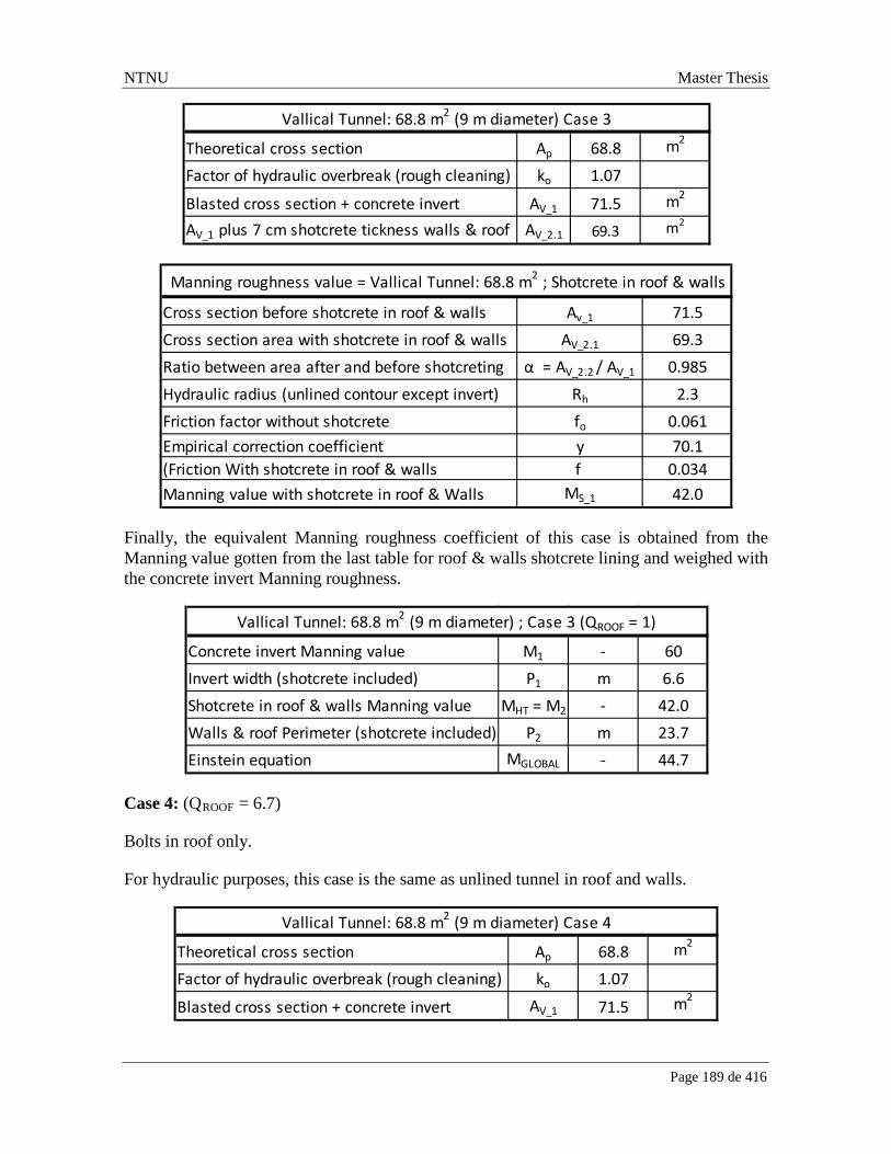
NTNU Master Thesis
Page 189 de 416
Finally, the equivalent Manning roughness coefficient of this case is obtained from the Manning value gotten from the last table for roof & walls shotcrete lining and weighed with the concrete invert Manning roughness.
Case 4: (QROOF = 6.7)
Bolts in roof only.
For hydraulic purposes, this case is the same as unlined tunnel in roof and walls.
Theoretical cross section Ap 68.8 m2
Factor of hydraulic overbreak (rough cleaning) ko 1.07
Blasted cross section + concrete invert AV_1 71.5 m2
AV_1 plus 7 cm shotcrete tickness walls & roof AV_2.1 69.3 m2
Vallical Tunnel: 68.8 m2 (9 m diameter) Case 3
Cross section before shotcrete in roof & walls Av_1 71.5Cross section area with shotcrete in roof & walls AV_2.1 69.3Ratio between area after and before shotcreting α = AV_2.2 / AV_1 0.985Hydraulic radius (unlined contour except invert) Rh 2.3Friction factor without shotcrete fo 0.061Empirical correction coefficient y 70.1(Friction With shotcrete in roof & walls f 0.034Manning value with shotcrete in roof & Walls MS_1 42.0
Manning roughness value = Vallical Tunnel: 68.8 m2 ; Shotcrete in roof & walls
Concrete invert Manning value M1 - 60Invert width (shotcrete included) P1 m 6.6Shotcrete in roof & walls Manning value MHT = M2 - 42.0Walls & roof Perimeter (shotcrete included) P2 m 23.7Einstein equation MGLOBAL - 44.7
Vallical Tunnel: 68.8 m2 (9 m diameter) ; Case 3 (QROOF = 1)
Theoretical cross section Ap 68.8 m2
Factor of hydraulic overbreak (rough cleaning) ko 1.07
Blasted cross section + concrete invert AV_1 71.5 m2
Vallical Tunnel: 68.8 m2 (9 m diameter) Case 4

NTNU Master Thesis
Page 190 de 416
The Manning roughness coefficient in unlined tunnel is given by the theoretical cross section:
MU (Ap = 64.3 m2) = 31.2
Case 5: (QROOF = 9.3)
Bolts in roof only.
This case can be considered equal to case 4. (Unlined walls and roof tunnel and concrete invert).
Concrete invert Manning value M1 - 60Invert width (Unlined tunnel) P1 m 6.7Manning tunnel in unlined walls & roof MHT = M2 - 31.2Walls & roof Perimeter (unlined) P2 m 24.0Einstein equation MGLOBAL - 34.4
Vallical Tunnel: 68.8 m2 (9 m diameter) ; Case 4 (QROOF = 6.7)
CaseRock Mass
ClassificationQROOF
Equivalent Manning
roughnessMGLOBAL
Hydraulic AreaAh
m2
Final rock support adopted for Roof and Walls
1 0.003 25.1 66.9Reinforced Shotcrete ribs D40/4 c/c 1.2 m + systematic bolting (Roof & Walls)
2 0.02 24.5 66.9Reinforced Shotcrete ribs E35/5 c/c 2.3 m ; systematic bolting (Roof & Walls)
3 1.0 44.7 69.3 7 cm Fibercrete in roof; 7 cm shotcrete in walls; systematic bolting (Roof & Walls)
4 6.7 34.4 71.5 Bolts in roof only
5 9.3 34.4 71.5 Bolts in roof only
Summary: Vallical Tunnel: 68.8 m2 (9 m diameter)

NTNU Master Thesis
Page 191 de 416
11,635,647 / 8,800 = 1322 USD/m
Rock MassClassification
QROOF
Chainage
m
Stretch Length
m
Equivalent Manning
CoefficientMGLOBAL
Final Hydraulic flow Area
Ah
m2
Final Hydraulic
RadiusRh
m
Energy Production
lossesEL
USD/m
Long term energy
losses per stretch
USD0.003 10000 - 10100 100 25.1 66.9 2.23 2515 251,521
1.0 10100 - 10300 200 44.7 69.3 2.27 719 143,8650.003 10300 - 10350 50 25.1 66.9 2.23 2515 125,761
6.7 10350 - 10850 500 34.4 71.5 2.31 1117 558,5600.02 10850 - 10950 100 24.5 66.9 2.23 2640 263,9706.7 10950 - 11300 350 34.4 71.5 2.31 1117 390,9920.02 11300 - 11400 100 24.5 66.9 2.23 2640 263,9706.7 11400 - 12550 1150 34.4 71.5 2.31 1117 1,284,6880.02 12550 - 12650 100 24.5 66.9 2.23 2640 263,9706.7 12650 - 13000 350 34.4 71.5 2.31 1117 390,9920.02 13000 - 13100 100 24.5 66.9 2.23 2640 263,9706.7 13100 - 13400 300 34.4 71.5 2.31 1117 335,1360.02 13400 - 13500 100 24.5 66.9 2.23 2640 263,9706.7 13500 - 14150 650 34.4 71.5 2.31 1117 726,1280.02 14150 - 14250 100 24.5 66.9 2.23 2640 263,9706.7 14250 - 14750 500 34.4 71.5 2.31 1117 558,5600.02 14750 - 14850 100 24.5 66.9 2.23 2640 263,9709.3 14850 - 15350 500 34.4 71.5 2.31 1117 558,5600.02 15350 - 15450 100 24.5 66.9 2.23 2640 263,9709.3 15450 - 16550 1100 34.4 71.5 2.31 1117 1,228,8320.02 16550 - 16650 100 24.5 66.9 2.23 2640 263,9709.30 16650 - 17400 750 34.4 71.5 2.31 1117 837,8400.02 17400 - 17500 100 24.5 66.9 2.23 2640 263,9706.7 17500 - 18300 800 34.4 71.5 2.31 1117 893,6969.3 18300 - 18700 400 34.4 71.5 2.31 1117 446,8480.02 18700 - 18800 100 24.5 66.9 2.23 2640 263,970
8800 11,635,647

NTNU Master Thesis
Page 192 de 416

NTNU Master Thesis
Page 193 de 416
8. ALTERNATIVES
8.1 Convenience of Tunnel Alignment Change
8.1.1 Introduction:
In general, an underground tunnel parallel to a predominant joint set is undesired, because it will cause drilling problems, poorer blastability and stability problems.
One potential solution to a parallelism between a predominant joint set and the tunnel alignment is to re-orient the last one in a way that increases the angle between the tunnel alignment and a certain joint direction. As a criterion 20 degrees apart between the tunnel alignment and the strike of a certain joint set is considered acceptable for avoiding stability problems caused by discontinuity orientation.
This chapter will analyze if some re-orientations applied to the existing tunnel layout are economically convenient.
8.1.2 Methodology
In practice blastability, drillability, total tunnel length and rock support are theoretically influenced by a re-orientation in tunnel alignment. These four variables influence the advance rate and the total cost, but some practical simplifications can be undertaken.
The Influence in advance rate from a slight change (less than 300 m) in tunnel length from one adit is insignificant as can be visualized in the next chart:
Theory

NTNU Master Thesis
Page 194 de 416
Blastability:
Scaling Cost
Explosives & Detonators Cost
Total tunnel length (heading length) from one adit:
Hauling Cost
Ventilation Cost
Electrical & Water supply Cost
Labor Cost
Drillability
Drilling Cost
Safety
Drillability recorded for different rock types taken from Shokrollah, Z Drill & Blast Tunneling. Advance rate.
From the last chart, it is possible to obtain an average DRI value for granite (representing the Batholith Melado) around 52 and Basalt around 44. (Basalt is the best representation of the Trapa Trapa rock formation in the absence of Andesite information). For alternative analysis.

NTNU Master Thesis
Page 195 de 416
8.1.3 Case 1: Vallical Tunnel Chainage 10,000 – 17,320 m
This alternative consists of a re-orientation to the Vallical tunnel alignment in 6 degrees (clockwise direction) in order to move it further away from the “Joint set 2” strike.
This new alignment will bring some other changes like:
Extend the tunnel length in 240 m (7560 m – 7320 m).
Extend the planned canal that crosses the Vallical brook located just upstream the Vallical tunnel in 270 m (red line).

NTNU Master Thesis
Page 196 de 416
The tunnel extension will compromise both fair rock mass and weakness zones, but the improvement because of the change in alignment only involves the tunnel in fair rock mass. (It is not expected any distinctive orientation in weakness zones, only crushed rock which makes no difference between the tunnel alignment alternatives analyzed).
The improvements of drillability and blastability are along the first 5000 m, excluding the last 2320 m because the last stretch has more than 20 degrees apart from the “Joint set 2” strike in the current situation.
For the current tunnel alignment, medium blastability and drillability (DRI = 49) has been considered, and the analysis will focus on changing from medium to good blastability in rock mass conditions just mentioned.
A longer tunnel not only means a cost rise because of the extension itself, but also for the whole tunnel: hauling, ventilation, Electrical & water supply and labor costs will increase.
Cost per round = 2166 USD/m
587
85
503269
525
197
Excavation Cost D&B USD2009/m: DRI = 49 ; Medium Blastability ; L = 4869 m
Drilling + Explosives + Scaling + Niches
Loading
Hauling
Ventilation + Electrical & Water Supply
Labour
Unforseen

NTNU Master Thesis
Page 197 de 416
Cost per round: 2065 USD/m
Cost reduction: (2166 USD/m – 2065 USD/m) * 4150 m = 419,150 USD
On the other hand, the tunnel extension has an investment cost that must be considered.
As it was said before there will be an extension not only in fair rock mass, but also in weakness zone. The tunnel length
489
85
508270
525
188
Excavation Cost D&B USD2009/m: DRI = 60 ; Good Blastability ; L = 4989 m
Drilling + Explosives + Scaling + Niches
Loading
Hauling
Ventilation + Electrical & Water Supply
Labour
Unforseen
Category UnitDRI = 60
Blastability = Good Tunnel length = 4989 m
DRI = 49Blastability = Medium
Tunnel length = 4869 m
Cost reductionΔ Cost
Drillability Cost USD/m 258 323 65Explosives Cost USD/m 201 217 16Scaling Cost USD/m 31 48 17Total Cost USD/m 489 587 98

NTNU Master Thesis
Page 198 de 416
Cost = 2382 USD/m
And also it is required an extension of the canal just upstream the Vallical tunnel:
Extension Tunnel Construction Period
673
85
508270
630
217
Excavation Cost D&B USD2009/m: lh = 3 m; L = 4989 m; Poor Blastability ; DRI = 49
Drilling + Explosives + Scaling + Niches
Loading
Hauling
Ventilation + Electrical & Water Supply
Labour
Unforseen
StretchRock mass
classificationQ - Method
Excavation Cost
Rock SupportCost
Total Unit Investment Cost
Gross Investment
Costm USD/m USD/m USD/m USD
Extension Poor Rock 34 0.02 2382 12,475 14,857 511,471Extension Good Rock 206 9.3 2065 247 2,312 475,369
Sum 240 986,839
Stretch Total Unit CostTotal Cost
m USD/m USDCanal cost 270 3500 945,000

NTNU Master Thesis
Page 199 de 416
Round cycle: 727 min
149.0
13.8
67.1
74.1
424.1
Cycle time (minutes) per round: Q = 0.02; lh = 3 m; Poor Blastability; DRI = 49 (Drilling time punished 10%)
Drilling + Charging + Blasting
Ventilation Break
Scaling Time
Load & Hauling
Rock Support
Working hour per week 120 h/weekDrilled length lh 3 mPull (Drillhole diameter = 48 mm) pr 0.91Round length pr*lh 2.73 mCycle Time 727 minAdvance rate 27.0 m/week
192.6
13.857.5
109.0
26.2
Cycle time (minutes): Q = 9.3 ; lh = 5 m ; Good Blastability ; DRI = 60
Drilling + Charging + Blasting
Ventilation Break
Scaling Time
Load & Hauling
Rock Support

NTNU Master Thesis
Page 200 de 416
Cycle time = 368 min.
The advance rate improvement is shown below:
Working hour per week 120 h/weekDrilled length lh 5 mPull (Drillhole diameter = 48 mm) pr 0.91
Round length pr*lh 4.55 mCycle Time 368 minAdvance rate 89.1 m/week
StretchRock Mass
Classification Q - Method
Advance rate Advance rate
m m/week weekExtension Poor Rock 34 0.02 27.0 1.28Extension Good Rock 206 9.30 89.1 2.31Sum 240 3.6
192.6
13.857.5
109.0
26.2
Cycle time (minutes): Q = 6.7 ; lh = 5 m, DRI = 49 ; Blastability Medium
Drilling + Charging + Blasting
Ventilation Break
Scaling Time
Load & Hauling
Rock Support

NTNU Master Thesis
Page 201 de 416
4150 𝑚82.3 𝑚/𝑤𝑒𝑒𝑘
− 4150 𝑚89.1 𝑚/𝑤𝑒𝑒𝑘
= 3.9 week
There is almost no difference in time spent.
8.1.4 Case 2: Vallical Tunnel Chainage 17,400 – 18,500 m
This alternative consists of an extension of the tunnel length at the end of the Vallical tunnel. The idea is to avoid the almost parallelism between the tunnel alignment and the joint sets 1 and 3.
Working hour per week 120 h/weekDrilled length lh 5 mPull (Drillhole diameter = 48 mm) pr 0.91
Round length pr*lh 4.55 mCycle Time 398 minAdvance rate 82.3 m/week

NTNU Master Thesis
Page 202 de 416
Total cost 2121 USD/m.
Total cost = 2017 USD/m
From the last two charts it is possible to deduct that the tunnel length factor is not a relevant variable in this analysis because the tunnel extension in 75 m (150/2 m) did not change the unit cost (USD/m) of Hauling, Ventilation, Electrical & Water Supply where tunnel length was the only variable changed which has an influence on them.
587
85
469261
525
193
Excavation Cost D&B USD2009/m: DRI = 49; Blastability = Medium L = 3931 m.
Drilling + Explosives + Scaling + Niches
Loading
Hauling
Ventilation + Electrical & Water Supply
Labour
Unforseen
489
85
469261
525
183
Excavation Cost D&B USD2009/m: DRI = 60; Blastability = Good; L = 4006 m.
Drilling + Explosives + Scaling + Niches
Loading
Hauling
Ventilation + Electrical & Water Supply
Labour
Unforseen

NTNU Master Thesis
Page 203 de 416
The main difference among these two charts are found in the first item which is “Drilling, explosives, scaling and niches” where both drillability in Drilling cost and blastability in Explosives and scaling costs have affected them.The Niches cost is 0 in both cases because the optimum cross section area is above 65 m2 and therefore is big enough to have dual transit of dump trucks.
The next table shows in detail the difference in unit cost between
Cost reduction: (2121 USD/m – 2017 USD/m) * 1100 m = 114,400 USD.
Rock support
From the previous alternative which also involves the Vallical tunnel is possible to obtain the advance rate for the existing situation which is 82.3 m/week when drillability is medium DRI = 49 and blastability is also medium. Change in advance rate because of tunnel length from one adit was not considered.
1100 𝑚82.3 𝑚/𝑤𝑒𝑒𝑘
− 1100 𝑚89.1 𝑚/𝑤𝑒𝑒𝑘
= 1.02 week
Category UnitDRI = 60
Blastability = Good Tunnel length = 4006 m
DRI = 49Blastability = Medium
Tunnel length = 3931 m
Cost reductionΔ Cost
Drillability Cost USD/m 258 323 65Explosives Cost USD/m 201 217 16Scaling Cost USD/m 31 48 17Total Cost USD/m 489 587 98
Extension Tunnel (150 m)
StretchRock Mass
ClassificationQ-Method
Excavated Cost
Rock SupportCost
Total Cost
Gross Investment
Costm USD/m USD/m USD/m USD
150 9.3 2017 247 2264 339,660
Stretch Advance rate Advance ratem m/week week
150 89.1 1.7

NTNU Master Thesis
Page 204 de 416
8.2 Convenience of extra adits
The feasibility study conceived one extra adit for both Castillo and Vallical tunnels. Both adits are located approximately at half of total tunnel length in each case.
The main benefits of considering an extra adit in a tunnel are an earlier tunnel completion and an investment cost reduction because of shortening tunnel stretches to be excavated.
In case a tunnel construction is within the project critical path, the benefit of an earlier tunnel completion becomes more relevant since it influences the plant commissioning and therefore the beginning of the revenues. The latter issue does not apply for this specific project, because tunnels are not within the critical path when extra adits are considered. This is due to the fact that there is a lag between tunnel completions and commissioning of project, mainly because of the supply and assembly of electromechanical equipments period which would take around 34 months starting from the same date as tunnels start construction.
In the case of Castillo tunnel the adit has a length of 963 m, requires an access road of 272 m and meets the Castillo tunnel at Chainage 6,100 m (measured from the intake) which is around 4,400 away from Castillo brook and 3400 m away from Vallical brook.
In the case of Vallical tunnel, the adit is 650 long, requires an access road of 874 m and meets the Vallical tunnel at Chainage 14,450 m which is around 4,400 m away from the Vallical brook and 4,400 m away from the downstream end of the Vallical tunnel.
If adits were not included in the construction layout, each tunnel (Castillo & Vallical) would be excavated from its two ends only. When an extra adit has met the main tunnel, it creates four advance stretches.
Once the extra adit reaches the main tunnel, the advance rate considered is normal for each side of the main tunnel. In practice this is not real, because some downtime occurs when two tunnel faces are being excavated from only one adit.
The portal construction period was considered as 1 month for all the cases.
For this analysis, medium blastability and drillability is considered for the water tunnels (Castillo & Vallical) as it was carried out in the optimum cross section since alignment of the main tunnels are kept.
Cross section area assumed for the adit is 40 m2. This was considered as the minimum area for the largest equipment needed to construct a tunnel of 64.3 m2 in the case of Castillo tunnel and 68.8 m2 in the case of Vallical tunnel.
Only direct cost was considered for both alternatives (with and without the extra adit) since there should not be significant difference in indirect cost, administration and planning cost, constructor profit, etc. between them.

NTNU Master Thesis
Page 205 de 416
8.2.1 Castillo Adit
8.2.1.1 Disadvantages
8.2.1.1.1 Castillo Extra Adit Cost
The extra adit was considered as 100 m of poor rock mass condition (surface weathering at the starting stretch) and 863 of good rock mass quality for the rest before meeting the Castillo tunnel. No weakness zone is visualized for the adit.
The resulting cost for the poor rock mass quality stretch is 1700 USD/m and it breaks down as follows:
The resulting cost for the fair rock mass quality stretch is 1525 USD/m and it breaks down as follows:
*
511
65
239172
559
155
Excavation Cost D&B USD2009/m: A s = 40 m2; lh = 3 m; L = 963 m (1000); Poor Blastability; DRI = 49
Drilling + Explosives + Scaling + Niches
Loading
Hauling
Ventilation + Electrical & Water Supply
Labour
Unforseen
444
65
239172
466
139
Excavation Cost D&B USD2009/m: As = 40 m2 ; lh = 5 m; L = 963 m (1000); Medium Blastability; DRI = 49
Drilling + Explosives + Scaling + Niches
Loading
Hauling
Ventilation + Electrical & Water Supply
Labour
Unforseen

NTNU Master Thesis
Page 206 de 416
From the previous two charts, it is possible to identify which costs are different: They are “Drilling + Explosives + Scaling + Niches”, “Labor” and “Unforeseen” costs. The first one is due to the difference in blastability and particularly it affects the explosives and scaling costs. The labor cost is affected by drilled length which is different because of change in rock mass quality. The unforeseen cost is explained by the change in the last two, because it was estimated as 10% of the total excavation cost.
Rock Support Cost
The rock support cost is determined in the same way as was done for the optimum cross section analysis. Particularly for 40 m2 and the rock conditions found for the extra adit, the relevant items are included in the next table:
The summary of the costs involved due to the extra adit for the Castillo tunnel is presented below:
In addition to the extra adit construction cost, it is needed an access road to the adit which unit cost was estimated from an average of different roads obtained from the feasibility report, resulting a value equal to 1325 USD/m.
8.2.1.2 Advantages
This chapter aims to quantify the benefits of an extra adit which are related to an earlier tunnel completion and an investment cost reduction because of shortening tunnel stretches to be excavated for the Castillo tunnel.
QROOF
Radial Bolts
USD/m
FibercreteUSD/m
ShotcreteUSD/m
RebarsUSD/m
Spiling bolts
USD/m
TotalRock
SupportUSD/m
0.003 1,257 2,652 3,349 711 4,122 12,09123 0 0 0 0 0 0
Castillo Extra Adit 963 m; A = 40 m2
ChainageStretch
m
Rock mass classification
Q-System
Excavation Cost
Rock Support
USD/m
Total Unit Cost
USD/m
Cost
USD0-100 100 0.003 1700 12,091 13,791 1,379,114
100-963 863 23 1525 0 1,525 1,316,075Sum 963 2,695,189
Cost access road to AditUnit Cost
USD/m length
mCostUSD
1325 272 360,400

NTNU Master Thesis
Page 207 de 416
8.2.1.2.1 Cost reduction in Castillo tunnel
With the extra adit, Castillo tunnel is excavated by four tunnel faces. This tunnel length reduction per adit reduces the unit cost of excavation. The first step is to determine the length of these stretches which is the same as to find the place where they meet each other. It is an iterative process to determine this because cost advance rate depends on tunnel stretch length and vice-versa.
The result of advance rate per geology stretch in the Castillo tunnel when an extra adit is taken into account is shown in the next table:
Tunnel length reference is the length that was used as input in the advance rate computation. Note that not always the length to be excavated in the Castillo tunnel coincides with the reference length used for advance rate estimate, since the length of the extra adit must be considered in the Castillo tunnel stretches where from this extra adit it is excavated (Castillo 3 & Castillo 4 shown in the table below).
Advance rate is not sensitive to small differences in tunnel length from one adit as 2684 m and 2679 m long or 2195 and 2168 m long. Between two similar tunnel lengths, one was taken as reference.
Once the advance rate for each stretch is known, it is possible to know accurately where the different advance stretches are met. This is shown in the following table:
Rock mass classification
Tunnel length
Tunnel length
reference
Drilled lenth
lhBlastability Drillability
Tunnel length
reference
Advance rate
Q-System m m m DRI m m/week0.003 2678 2678 2678 25.5
1722 2685 3.0 Poor 491232 2195 (10% punished 2195 25.32168 2168 drilled time)
1.9 2678 2678 2678 80.81722 2685
2.6 2678 2678 5.0 Medium 49 2678 84.41232 2195 2195 83.32168 2168
23 2168 2168 2168 89.3

NTNU Master Thesis
Page 208 de 416
From the previous table, it is possible to say that:
Castillo 1 & 3 meet each other at chainage 4378 m which is 2678 m away from the Castillo brook (Or upstream end of Castillo tunnel).
Castillo 2 & 4 meet each other at chainage 7332 m which is 2168 m away from the Vallical brook (Or downstream end of Castillo tunnel).
Extra adit meets Castillo tunnel at Chainage 6100, and the first stretch toward Castillo brook is 650 m long and toward Vallical brook is 280 m long.
Once the length of each stretch is known, it is possible to obtain the excavation cost which is:
Rock mass classification
Q ROOF
Identification of stretch ChainageStretch Length
m
Cumulative distance Castillo 1
m
Cumulative distance Castillo 2
m
Cumulative distance Castillo 3
m
Cumulative distance Castillo 4
m
0.003 Surface weathering 1700 - 1850 150 1501.9 Fair Andesite - Fair tunnel orientation 1850 - 3900 2050 22002.6 Fair Andesite - Good Orientation 3900 - 4330 430 2630
0.003 Inferred fault zone around Las Mulas brook 4330 - 4430 100 2678 17221.9 Fair Andesite - Good tunnel Orientation 4430 - 5350 920 1670
0.003 Inferred fault zone around Las Yeguas brook 5350 - 5450 100 750
2.6 Fair Andesite - Good tunnel Orientation 5450 - 6380 930 650 280
0.003 Inferred fault zone I from aerial photos 6380 - 6480 100 3802.6 Fair Andesite - Good tunnel Orientation 6480 - 7670 1190 2168 1232
0.003 Inferred fault zone II from aerial photos 7670 - 7770 100 183023 Good Andesite - Good Orientation 7770 - 9400 1630 1730
0.003 Surface Weathering 9400 - 9500 100 100Sum 1700 - 9500 7800
Start End

NTNU Master Thesis
Page 209 de 416
The rock support cost is the same as considered in the economic cross section analysis. Below, just the final rock support cost is presented for 64.3 m2 or 8.7 m diameter for a “horse shoe” shape tunnel:
Finally, the Castillo tunnel has a new cost of 34,689,965 USD. Details for each stretch are shown below:
D & B Excavation Cost : 64.3 m2
Stretch
Drilled length
lh
m
BlastabilityRock mass
classification Q-system
Length reference
m
Excavation Cost
USD/m
Castillo 1 (L = 2678 m) 3 Poor 0.003 2678 2187Castillo 2 (L = 2168 m) 2168 2156Castillo 3 (L = 1722 m) 2685 2187Castillo 4 (L = 1232 m) 2195 2157Castillo 1 (L = 2678 m) 5 Medium 1 -23 2678 1983Castillo 2 (L = 2168 m) 2168 1950Castillo 3 (L = 1722 m) 2685 1983Castillo 4 (L = 1232 m) 2195 1952
Rock mass classification
QROOF
TotalRock Support
USD/m
0.003 15,3341.9 1,2552.6 1,09523 0

NTNU Master Thesis
Page 210 de 416
This final cost for Castillo tunnel is almost 600,000 USD cheaper than the cost obtained when no extra adit was computed. The exact cost in that case is 35,273,002 USD and the details are shown in the optimum cross section analysis.
8.2.1.2.2 Earlier tunnel completion
As long as the extra adit does not reach the Castillo tunnel, only two tunnel faces will be working on the Castillo tunnel. Once the extra adit reaches the Castillo tunnel, four tunnel faces will be working on the Castillo Tunnel. Therefore it is of prime importance to determine when the extra adit reaches the Castillo tunnel.
Advance rate Castillo Adit
In poor rock mass condition the adit advance rate is shown in the next chart:
Rock mass classification
Q ROOF
Stretch Length
mChainage
D & B CostUSD/m
Cost concreteinvert +
wire meshUSD/m
Cost Rock SupportUSD/m
TotalGross
Cost/m
Total Cost/stretch
USD
0.003 150 1700 - 1850 2,187 367 15,334 17,888 2,683,1621.9 2050 1850 - 3900 1,983 367 1,255 3,604 7,388,7362.6 430 3900 - 4330 1,983 367 1,095 3,445 1,481,275
0.003 100 4330 - 4430 2,187 367 15,334 17,888 1,788,7741.9 920 4430 - 5350 1,983 367 1,095 3,445 3,169,240
0.003 100 5350 - 5450 2,187 367 15,334 17,888 1,788,7742.6 930 5450 - 6380 1,974 367 1,095 3,435 3,195,008
0.003 100 6380 - 6480 2,157 367 15,334 17,858 1,785,7742.6 1190 6480 - 7670 1,951 367 1,095 3,413 4,061,776
0.003 100 7670 - 7770 2,157 367 15,334 17,858 1,785,77423 1630 7770 - 9400 1,950 367 0 2,317 3,775,897
0.003 100 9400 - 9500 2,157 367 15,334 17,858 1,785,7747800 SUM 34,689,965

NTNU Master Thesis
Page 211 de 416
Cycle time 728 min
Correction factor for tunnel length (963 m) kle = 1.11
Total cycle time: (728-469.2) *(1.11-1) + 728 = 755 min. (Tunnel length only affects the excavation advance rate).
And for the tunnel stretch crossing good rock mass, the cycle time is 330 min (without tunnel length correction factor) and it breaks down as follows:
114.5
8.6
51.2
84.9469.2
Cycle time (minutes) per round: Q = 0.003; lh = 3 m; Poor Blastability ; DRI = 49 (Drilling time punished 10% extra)
Drilling + Charging + Blasting
Ventilation Break
Scaling Time
Load & Hauling
Rock Support
Working hour per week 120 h/weekDrilled length lh 3 m
Pull pr 91%
Round length pr*lh 2.73 mCycle Time min 755 minAdvance rate 26.0 m/week

NTNU Master Thesis
Page 212 de 416
Cycle time = 147.9 + 8.6 + 41.9 + 130.9 = 330 min
Correction factor for tunnel length (963 m) kle = 1.1
Total cycle time: 330 * 1.11 = 364 min
Also the access road from the existing road to the extra adit requires some days to be constructed and the details are shown below:
147.9
8.641.9
130.9
Cycle time (minutes) per round: Q = 23 ; lh = 5 m ; Medium Blastability ; DRI = 49
Drilling + Charging + Blasting
Ventilation Break
Scaling Time
Load & Hauling
Working hour per week 120 h/weekDrilled length lh 3 m
Pull pr 91%
Round length pr*lh 4.55 mCycle Time min 364 minAdvance rate 90.1 m/week
Stretch mRock mass
classification Q-System
Advance rate m/week
Construction time
month/stretch0-100 100 0.003 26.0 0.9
100-963 863 23 90.1 2.2Sum 963 3.1

NTNU Master Thesis
Page 213 de 416
Finally one month was considered as portal construction period.
Therefore, construction Castillo tunnel from the extra adit starts after 4.3 months (3.1 month + 0.2 month + 1 month). The extra adit comes out in the Castillo tunnel at Chainage 6100 m, in a stretch where the rock is classified as 2.6 in the Q system between chainage 5450 m and 6380 m (6380 m – 5450 m = 930 m long). Hence, in the Castillo tunnel, 650 m of this 930 m stretch will be constructed towards upstream and 280 m towards downstream at an advance rate equal to 84.4 m/week for either direction.
The time elapsed to reach the Chainage 5450 m and 6380 m respectively in the Castillo tunnel from Chainage 6100 m is provided in the next table:
With regard to the two Castillo tunnel ends, they also require an access road. Access road required to the upstream end adit is 150 m and the downstream end adit is 331 m.
In addition to access road construction time, one month is added in each Castillo tunnel end for portal construction time before tunnel excavation starts. Therefore the upstream end or “Castillo 1” starts 1.1 months (0.1 month + 1 month) after road construction initiation. Likewise, the downstream end or “Castillo 2” starts 1.2 months after road construction initiation.
Access road 272 mRoad advance rate 50 m/dayConstruction period 5.44 daysConstruction period 0.2 month
Advance rateChainage5450 -6380
Distance time elapsed Distance time elapsedm/week m month m month
- 0 4.3 0 4.384.4 650 6.1 280 5.1
To Castillo Brook (Or upstream)
To Vallical brook (Or downstream)
Upstream end access roadUpstream end 150 mRoad advance rate 50 m/daytime elapsed 3 daytime elapsed 0.1 month
Downstream end access roadUpstream end 331 mRoad advance rate 50 m/daytime elapsed 7 daytime elapsed 0.2 month

NTNU Master Thesis
Page 214 de 416
Finally, the time elapsed at the end of each stretch from each adit is shown in the following table:
From the previous table, it is possible to say that:
The first stretch of “Castillo 1” tunnel (Chainage 1700 - 1850) is completed after 2.5 months (green color), which is the sum of the first stretch equal to 150 m long in 1.4 months and 1.1 months related to road construction and portal. The time consumption for the following stretches until the end (brown cell) is only related to the advance rate in the tunnel.
For “Castillo 2”, “Castillo 3” and “Castillo 4” the computation is exactly the same. The green cell is the sum of the previous construction time consumptions plus the time spent to excavate the corresponding stretch. The following stretches until the end (brown cell) is only related to the advance rate in the tunnel.
Castillo 1 & 3 meet each other after 10 months and Castillo 2 & 4 meet each other after 8.3 months.
Therefore, Castillo tunnel is completed after 10.0 months (or 3.3 trimesters). This is 3.9 months (or 1.3 trimesters) faster than eliminating the extra adit.
8.2.1.3 Evaluation
This chapter aims to trades off the advantages and disadvantages of an extra adit in economic terms for the Castillo tunnel.
Chainage
Stretch Length
m
Advance rate
m/week
Advance rate
month/stretch
Cumulative time elapsed
Castillo 1month
Cumulative time elapsed
Castillo 2month
Cumulative time elapsed
Castillo 3month
Cumulative time elapsed
Castillo 4month
1700 - 1850 150 25.5 1.4 2.51850 - 3900 2050 80.8 5.9 8.43900 - 4330 430 84.4 1.2 9.64330 - 4430 100 25.5 0.9 10.0 10.04430 - 5350 920 84.4 2.5 8.65350 - 5450 100 25.5 0.9 6.0
5450 - 6380 930 84.4 2.6 6.1 5.1
6380 - 6480 100 25.3 0.9 6.06480 - 7670 1190 83.3 3.3 8.3 8.37670 - 7770 100 25.3 0.9 7.47770 - 9400 1630 89.3 4.3 6.59400 - 9500 100 25.3 0.9 2.21700 - 9500 7800
Start End

NTNU Master Thesis
Page 215 de 416
About the cost, not only the gross investment cost already estimated must be considered when evaluating both alternatives, but also the interest on the capital invested (or interest under construction) must be included in order to quantify the benefit of an earlier tunnel completion which is the case of the extra adit. This extra cost is called compounding the gross investment.
The total cost is assumed to be paid evenly distributed and monthly. This monthly payment is the total gross investment Ig divided by the number of months 𝑛.
The compounding factor 𝑅 moves forward all the regular monthly payment to the end of the tunnel construction:
𝑅 =(1 + 𝑖)𝑛 − 1
𝑖
Where 𝑖 represents the monthly interest during construction and 𝑛 represents in this case the number of months.
iANNUAL = 10% => iMONTHLY = (1+ iANNUAL)1/12 - 1 = 0.8%.
Finally the value obtained is again compounded to the commissioning of the plant which would occur 1 year after the tunnel completion.
Therefore, if the Castillo tunnel is not part of the critical path, an extra adit is not convenient because an earlier completion benefit and a cost reduction benefit because of a shorter advance stretches does not pay off the extra cost of the adit itself and its required access road.
Castillo Tunnel is not as part of critical path Without Adit With Adit Difference
Access Road + Portal + Castillo Tunnel n Month 13.9 10.0 3.9
Gross Investment Cost Castillo Tunnel USD 35,273,002 34,689,926 583,076
Adit Cost (963 m) USD 0 2,695,189 -2,695,189
Access road to adit (272 m) USD 0 360,400 -360,400
Total Gross Investment Cost Ig USD 35,273,002 37,745,515 -2,472,513
Equivalent monthly payment Ig/n USD 2,537,626 3,774,551 -1,236,925
Compounding factor R 14.6 10.4 4.3
Investment cost compounding R*Ig/n USD 37,145,857 39,129,168 -1,983,311
Total Cost at Commissioning R*Ig/n*(1+i)12 USD 40,860,443 43,215,741 -2,355,298

NTNU Master Thesis
Page 216 de 416
8.2.2 Vallical Adit
8.2.2.1 Disadvantage
8.2.2.1.1 Vallical Extra Adit Cost
The extra adit was considered as 100 m of poor rock mass condition (surface weathering at the starting stretch) and 550 of fair rock mass quality for the rest before meeting the Vallical tunnel. No weakness zone is visualized for the adit.
The resulting cost for the poor rock mass quality stretch is 1700 USD/m and it breaks down as follows:
511 + 65+ 239 +172 + 559 + 155 = 1700 USD/m
511
65
239172
559
155
Excavation Cost D&B USD2009/m: A s = 40 m2; lh = 3 m; L = 650 m (1000); Poor Blastability; DRI = 49
Drilling + Explosives + Scaling + Niches
Loading
Hauling
Ventilation + Electrical & Water Supply
Labour
Unforseen
444
65
239172
466
139
Excavation Cost D&B USD2009/m: As = 40 m2 ; lh = 5 m; L = 650 m; (1000); Medium Blastability; DRI = 49
Drilling + Explosives + Scaling + Niches
Loading
Hauling
Ventilation + Electrical & Water Supply
Labour
Unforseen

NTNU Master Thesis
Page 217 de 416
444 + 65 + 239 + 172 + 466 +139 = 1525 USD/m
Rock support
The rock support cost is determined in the same way as was done for the optimum cross section analysis. Particularly for 40 m2 and the rock conditions found for the extra adit, the relevant items are included in the next table:
The summary of the costs involved due to the extra adit for the Vallical tunnel is presented below:
As it was said before, the estimated average unit cost for road is 1325 USD/m. This is used to quantify the cost of the access road needed for the extra adit.
8.2.2.2 Advantage
This chapter aims to quantify the benefits of an extra adit which are related to an earlier tunnel completion and an investment cost reduction because of shortening tunnel stretches to be excavated for the Vallical tunnel.
8.2.2.2.1 Cost reduction in Vallical tunnel
Vallical extra adit A = 40 m2
QROOF Radial Bolts
USD/m
Fibercrete
USD/m
Shotcrete
USD/m
Rebars
USD/m
Spiling bolts
USD/m
TotalRock Support
USD/m0.02 873 2,652 1,398 464 4,122 9,5096.67 0 0 0 0 0 0
Vallical Adit 650 m ; A = 40 m2
ChainageRock mass
classification Q-System
length m
Excavation Cost
USD/m
Rock Support
USD/m
Total Unit Cost
USD/m
Cost
USD0 - 100 0.02 100 1700 9,509 11,209 1,120,872
100 - 650 6.7 550 1525 0 1,525 838,7501,959,622
Cost access road to extra AditUnit Cost Road length Cost
USD/m m USD1325 834 1,105,050

NTNU Master Thesis
Page 218 de 416
In Vallical tunnel one extra adit also will trigger a tunnel length reduction per adit compared to the alternative without extra adits, since four tunnel faces will be working in parallel instead of two from the ends. It is vital to know the advance rate from each tunnel face in order to find the place where they meet each other which determines the length of each stretch.
The result of advance rate per geology stretch in the Vallical tunnel when an extra adit is taken into account is shown in the next table:
Tunnel length reference is the length that was used as input in the advance rate computation. Some tunnel length references are longer than the corresponding tunnel length. Those cases are including the adit length in addition to the tunnel length for the excavation advance rate.
Once the advance rate for each stretch is known, it is possible to know accurately where the different advance stretches are met. This is shown in the following table:
Rock mass classification
Tunnel length
Tunnel length
reference
Drilled lenth lh
Blastability Drillability Advance rate
Q-System m m m DRI m/week0.003 3019 3019 25.10.02 3019 3019 3.0 Poor 49 27.0
2194 2194 (10% punished 26.71431 2081 drilling time) 26.72156 2806 26.9
1.0 3019 3019 66.16.7 3019 3019 5.0 Medium 49 82.1
2194 2194 80.31431 2081 80.02156 2806 81.6
9.3 2194 2194 80.32156 2806 81.6

NTNU Master Thesis
Page 219 de 416
From the previous table, it is possible to say that:
Vallical 1 & 3 meet each other at chainage 13,019 m which is 3,019 m away from the Vallical brook (Or upstream end of Vallical tunnel).
Castillo 2 & 4 meet each other at chainage 16,606 m which is 2194 m away from the downstream end of Vallical brook.
Extra adit meets Castillo tunnel at Chainage 14,250 m, and the first stretch toward Vallical brook is 200 m long and toward Vallical brook is 300 m long.
Once the length of each stretch is known, it is possible to obtain the excavation cost which is:
QROOF Identification of stretch ChainageLength
m
Cumulative distanceVallical 1
m
Cumulative distance Vallical 2
m
Cumulative distance Vallical 3
m
Cumulative distance Vallical 4
m
0.003 Surface weathering & inferred fault zone 3 10000 - 10100 100 1001.0 Good orientation - Fair Andesite 10100 - 10300 200 300
0.003 Weakness zone - Change in rock formation 10300 - 10350 50 3506.7 Fair Orientation - Fair Granite 10350 - 10850 500 850
0.02 Inferred fault zone 4 10850 - 10950 100 9506.7 Fair Orientation - Fair Granite 10950 - 11300 350 1300
0.02 Inferred fault zone 5 11300 - 11400 100 14006.7 Fair Orientation - Fair Granite 11400 - 12550 1150 2550
0.02 Inferred fault zone 6 12550 - 12650 100 26506.7 Fair Orientation - Fair Granite 12650 - 13000 350 3000
0.02 Inferred fault zone 7 13000 - 13100 100 3019 14316.7 Fair Orientation - Fair Granite 13100 - 13400 300 1350
0.02 Inferred fault zone 8 13400 - 13500 100 10506.7 Fair Orientation - Fair Granite 13500 - 14150 650 950
0.02 Inferred fault zone 9 14150 - 14250 100 3006.7 Fair Orientation - Fair Granite 14250 - 14750 500 200 300
0.02 Inferred fault zone 10 14750 - 14850 100 4006.7 Fair Orientation - Fair Granite 14850 - 15350 500 900
0.02 Inferred fault zone 11 15350 - 15450 100 10009.3 Good orientation - Fair Granite 15450 - 16550 1100 2100
0.02 Inferred fault zone 12 16550 - 16650 100 2194 21569.30 Good orientation - Fair Granite 16650 - 17400 750 21500.02 Inferred Fault zone 13 17400 - 17500 100 14006.7 Fair Orientation - Fair Granite 17500 - 18300 800 13009.3 Good orientation - Fair Granite 18300 - 18700 400 500
0.02 Surface weathering 18700 - 18800 100 1008800
Start End

NTNU Master Thesis
Page 220 de 416
The rock support cost is the same as considered in the economic cross section analysis. Below, just the final rock support cost is presented for 68.8 m2 or 9.0 m diameter for a “horse shoe” shape tunnel:
Finally, the Vallical tunnel has a new cost of 40,045,110 USD. Details for each stretch are shown below:
D & B Excavation Cost : 68.8 m2
StretchTunnel length
m
lh
m
Blastability Q range Length reference
m
Excavation Cost
USD/mVallical 1 3019 3 Poor 0.003 - 002 3019 2297Vallical 2 2194 3 Poor 0.003 - 002 2194 2244Vallical 3 1431 3 Poor 0.003 - 002 2081 2237Vallical 4 2156 3 Poor 0.003 - 002 2806 2284Vallical 1 3019 5 Medium 1 -23 3019 2087Vallical 2 2194 5 Medium 1 -23 2194 2032Vallical 3 1431 5 Medium 1 -23 2081 2024Vallical 4 2156 5 Medium 1 -23 2806 2073
Rock mass classification
QROOF
TotalRock
SupportUSD/m
0.003 15,8630.02 12,4751.0 2,1356.7 2479.3 247

NTNU Master Thesis
Page 221 de 416
This final cost for Vallical tunnel is almost 800,000 USD cheaper than the cost obtained when no extra adit was computed. The exact cost in that case is 40,830,310 USD and the details are shown in the optimum cross section analysis.
Rock mass classification
Q ROOF
Stretch Length
m
Chainage
D & B Cost
USD/m
Cost concreteinvert + wire
meshUSD/m
Rock SupportCost
USD/m
TotalUnitCost
USD/m
Total Cost/stretch
USD
0.003 100 10000 - 10100 2297 379 15,863 18,539 1,853,9151.0 200 10100 - 10300 2087 379 2,135 4,602 920,314
0.003 50 10300 - 10350 2297 379 15,863 18,539 926,9576.7 500 10350 - 10850 2087 379 247 2,714 1,356,7700.02 100 10850 - 10950 2297 379 12,475 15,151 1,515,1146.7 350 10950 - 11300 2087 379 247 2,714 949,7390.02 100 11300 - 11400 2297 379 12,475 15,151 1,515,1146.7 1150 11400 - 12550 2087 379 247 2,714 3,120,5710.02 100 12550 - 12650 2237 379 12,475 15,091 1,509,1146.7 350 12650 - 13000 2024 379 247 2,651 927,6890.02 100 13000 - 13100 2237 379 12,475 15,091 1,509,1146.7 300 13100 - 13400 2024 379 247 2,651 795,1620.02 100 13400 - 13500 2237 379 12,475 15,091 1,509,1146.7 650 13500 - 14150 2024 379 247 2,651 1,722,8510.02 100 14150 - 14250 2237 379 12,475 15,091 1,509,1146.7 500 14250 - 14750 2053 379 247 2,680 1,339,9700.02 100 14750 - 14850 2284 379 12,475 15,138 1,513,8146.7 500 14850 - 15350 2073 379 247 2,700 1,349,7700.02 100 15350 - 15450 2284 379 12,475 15,138 1,513,8149.3 1100 15450 - 16550 2073 379 247 2,700 2,969,4940.02 100 16550 - 16650 2284 379 12,475 15,138 1,513,8149.30 750 16650 - 17400 2032 379 247 2,659 1,993,9050.02 100 17400 - 17500 2244 379 12,475 15,098 1,509,8146.7 800 17500 - 18300 2032 379 247 2,659 2,126,8329.3 400 18300 - 18700 2032 379 247 2,659 1,063,4160.02 100 18700 - 18800 2244 379 12,475 15,098 1,509,814
8800 40,045,110

NTNU Master Thesis
Page 222 de 416
8.2.2.2.2 Earlier tunnel completion
As long as the extra adit does not reach the Castillo tunnel, only two tunnel faces will be working on the Castillo tunnel. Once the extra adit reaches the Castillo tunnel, four tunnel faces will be working on the Castillo Tunnel. The extra adit will let to finish earlier the tunnel and its improvement relies on how fast the extra adit reaches the Vallical tunnel.
Therefore it is needed to know access road advance rate to the adit and the adit advance rate.
In poor rock mass condition the adit advance rate is shown in the next chart:
114.5 + 8.6 + 51.2 + 84.6 + 415.6 = 675 min
Correction factor for tunnel length (650 m) kle = 1.143 (Reference [8] only has information from 1000 m and longer tunnel, but curve was extended).
Total cycle time: (675– 415.6) *(1.143 - 1) + 675 = 712 min. (Tunnel length only affects the excavation advance rate).
114.5
8.6
51.2
84.9415.6
Cycle time (minutes) per round: Q = 0.02; lh = 3 m; Blastability Poor ; L = 650 m ; DRI = 49 ( Drilling time punished 10 % )
Drilling + Charging + Blasting
Ventilation Break
Scaling Time
Load & Hauling
Rock Support
Working hour per week 120 h/weekDrilled length lh 3 m
Pull pr 91%
Round length pr*lh 2.73 mCycle Time 712 minAdvance rate 27.6 m/week

NTNU Master Thesis
Page 223 de 416
147.9 + 8.6 + 41.9 + 130.9 = 329 min
Correction factor for tunnel length (650 m) kle = 1.143
329* 1.143 = 376 min
Also, the access road from the existing road to the extra adit requires a significant period of time to be constructed and the details are shown below:
147.9
8.641.9
130.9
Cycle time (minutes) per round: Q = 6.7 ; lh = 5 m ; Medium Blastability ; DRI = 49 ; L = 650 m
Drilling + Charging + Blasting
Ventilation Break
Scaling Time
Load & Hauling
Working hour per week 120 h/weekDrilled length 5 m
Pull 91%
Round length 4.55 mCycle Time min 376 minAdvance rate 87.0 m/week
Chainagelength
m
Rock mass classification
Q-System
Advance rate
m/week
Construction time
month/stretch0 - 100 100 0.02 27.6 0.8100 - 650 550 6.7 87.0 1.5
Sum 650 2.3

NTNU Master Thesis
Page 224 de 416
Finally one month was considered for portal construction period.
Hence, construction Vallical tunnel from the extra adit starts after 7 months (2.3 month + 3.7 month + 1 month).
The extra adit comes out in the Vallical tunnel at Chainage 14,450 m, in a stretch where the rock is classified as 6.7 in the Q system between chainage 14,250 m and 14,750 m (14,750 m – 14,250 m = 500 m long). Therefore, in the Vallical tunnel, 200 m of this 500 m stretch will be constructed toward upstream and 300 m toward downstream at an advance rate equal to 81.6 m/week for either direction.
The time elapsed to reach the Chainage 14,250 m and 14,750 m respectively in the Vallical tunnel from Chainage 14,450 m is provided in the next table:
With regard to the two Vallical tunnel ends, they also require an access road. Access road required to the upstream end adit is 377 m and the downstream end adit is 8760 m.
Road construction time before extra aditRoad length from road "Vallical brook - Cavern" to adit 834 mRoad length stretch of Vallical brook - Cavern 4,660 mTotal road length 5,494 mAdvance rate road 50 m/dayConstruction period 110 dayConstruction period 3.7 month
Advance rateChainage
14250 -14750Distance time elapsed Distance time elapsed
m/week m month m month - 0 7.0 0 7.0
81.6 200 7.6 300 7.8
To Vallical Brook (Or upstream)
To downstream
Vallical 1: Acces roadRoad length 377 mAdvance rate 50 m/daytime elapsed 8 day
time elapsed 0.3 month

NTNU Master Thesis
Page 225 de 416
In addition to access road construction time, one month is added in each Vallical tunnel end for portal construction time before tunnel excavation starts. Therefore the upstream end or “Vallical 1” starts 1.3 months (0.3 month + 1 month) after road construction initiation. Likewise, the downstream end or “Castillo 2” starts 6.8 months (5.8 months + 1 month) after road construction initiation.
Finally, the time elapsed at the end of each stretch from each adit is shown in the following table:
Vallical 4: Acces road
Road length 8760 m
Advance rate 50 m/day
time elapsed 175 daytime elapsed 5.8 month

NTNU Master Thesis
Page 226 de 416
From the previous table, it is possible to say that:
The first stretch of “Vallical 1” tunnel (Chainage 10000 - 10100) is completed after 2.2 months (green color), which is the sum of the first stretch equal to 100 m long in 0.9 months and 1.3 months related to road construction and portal. The time consumption for the following stretches until the end (brown cell) is only related to the advance rate in the tunnel.
For “Vallical 2”, “Vallical 3” and “Vallical 4” the computation is exactly the same. The green cell is the sum of the previous construction time consumptions plus the time spent to excavate the corresponding stretch. The following stretches until the end (brown cell) is only related to the advance rate in the tunnel.
Chainage
Stretch Length
m
Rock MassQROOF
Advance rate
m/week
Advance rate
month/stretch
Cumulative time elapsed
Vallical 1month
Cumulative time elapsed
Vallical 2month
Cumulative time elapsed
Vallical 3month
Cumulative time elapsed
Vallical 4month
10000 - 10100 100 0.003 25.1 0.9 2.210100 - 10300 200 1.0 66.1 0.7 2.910300 - 10350 50 0.003 25.1 0.5 3.410350 - 10850 500 6.7 82.1 1.4 4.810850 - 10950 100 0.02 27.0 0.9 5.610950 - 11300 350 6.7 82.1 1.0 6.611300 - 11400 100 0.02 27.0 0.9 7.511400 - 12550 1150 6.7 82.1 3.3 10.812550 - 12650 100 0.02 27.0 0.9 11.612650 - 13000 350 6.7 82.1 1.0 12.613000 - 13100 100 0.02 26.7 0.9 12.8 12.813100 - 13400 300 6.7 80.0 0.9 12.113400 - 13500 100 0.02 26.7 0.9 11.213500 - 14150 650 6.7 80.0 1.9 10.314150 - 14250 100 0.02 26.7 0.9 8.414250 - 14750 500 6.7 81.6 1.4 7.6 7.814750 - 14850 100 0.02 26.9 0.9 8.714850 - 15350 500 6.7 81.6 1.4 10.115350 - 15450 100 0.02 26.9 0.9 11.015450 - 16550 1100 9.3 81.6 3.1 14.216550 - 16650 100 0.02 26.9 0.9 14.6 14.616650 - 17400 750 9.30 80.3 2.2 14.217400 - 17500 100 0.02 26.7 0.9 12.117500 - 18300 800 6.7 80.3 2.3 11.218300 - 18700 400 9.3 80.3 1.2 8.918700 - 18800 100 0.02 26.7 0.9 7.7
8800Start End

NTNU Master Thesis
Page 227 de 416
Vallical 1 & 3 meet each other after 12.8 months and Vallical 2 & 4 meet each other after 14.6 months.
Therefore, Castillo tunnel is completed after 14.6 months (or 3.3 trimesters). This is 5.6 months (or 1.9 trimesters) faster than eliminating the extra adit.
8.2.2.3 Evaluation
This chapter aims to trades off the advantages and disadvantages of an extra adit in economic terms for the Vallical tunnel.
The evaluation procedure is exactly the same as that applied in the extra adit for Castillo tunnel. The results are shown below:

NTNU Master Thesis
Page 228 de 416
Based on the calculations undertaken here, an extra adit for the Vallical tunnel is not economically convenient as it occurred for the Castillo tunnel. In both situations a delay in plant commissioning were not quantified since neither Castillo nor Vallical tunnel are in the critical path.
8.3 Convenience of TBM
This section will analyze qualitatively the convenience of TBM utilization in the Melado Hydropower Project. In general, there is a consensus about the following advantages using TBM excavation which are:
- It requires less rock support.
- It gives smoother tunnel walls and reduced head loss in water tunnels.
- Longer tunnel sections can be excavated between adits.
- It has higher tunnelling capacity.
- It gives better working conditions for the crew.
Also, there is a consensus about the following disadvantages of TBM:
- More (better) geological information from the pre-investigation stage is required.
- It is more sensitive to tunneling problems in poor rock mass conditions.
- It is a less flexible method than drill & blast method.
Also, in general the cost of TBM is higher than drill and blast but it could be traded off by a smoother contour and a faster advance rate.
Based on the above, and the facts about this project, one can mention the following with regard to TBM in this project that:
Vallical Tunnel is not part of critical path Without Adit With Adit DifferenceTunnel + Portal Constraction Period n Month 20.3 14.6 5.6Gross Investment Cost Vallical Tunnel USD 40,830,310 40,045,110 785,200Extra adit cost (650 m) USD 0 1,959,622 -1,959,622Access Road to Vallical Adit (834 m) USD 0 1,105,050 -1,105,050Total Gross Investment Cost USD 40,830,310 43,109,782 -2,279,472Compounding factor R 21.9 15.9 6.0
Investment cost compounding R*Ig/n USD 44,123,443 45,533,569 -1,410,126
Total Cost at Commissioning R*Ig/n*(1+i)12 USD 48,535,787 50,086,926 -1,551,139

NTNU Master Thesis
Page 229 de 416
The benefit of higher advance rate is not so much appreciated in this project since tunnel construction is not in the critical path. If there was an earlier plant commissioning because of a higher advance rate, TBM excavation method would be very appreciated.
The benefit of eliminating adits is not appreciated in this project because with Drill & Blast is also achieved.
The uncertainties related to the character of weakness zone are not favorable for TBM, where a wrong tunnel mapping can even cause that the machine get stuck and support at the face is in general more difficult to install.
Of course, there are some benefits that Drill & Blast will never achieved like a smoother tunnel contour and better working conditions for the crew, but based on the facts given above, the recommendation is not to considerer TBM.
.

NTNU Master Thesis
Page 230 de 416
9. CONCLUSION & RECOMENDATION
The first task of this thesis was to improve the evaluation of the engineering geological conditions which are the key input parameters for a tunnel planning. The way to achieve this was by means of a combination between a correlation of different statistical methods, analysis of field data and the incorporation of input data of similar rock conditions.
Among the findings that are completely new for this project one can point out:
Blocky Granite/ Blocky Andesite:
Based on the rock mass description, tunnel diameter and core drillings log data, there is consistency that both rock types that represents the two relevant rock formations would behave as blocky in between weakness zones, meaning that the main challenge for these stretches would be block fall and could become as buckling in case of high stress level.
Eventual problems in invert for inferred weakness zones located in Trapa-Trapa rock formation:
The numerical modeling showed that a high level of in situ stress in poor rock mass conditions could lead to lift the invert where a thicker concrete slab could be required.
Eventual water ingress in inferred Trapa-Trapa weakness zones:
From different documented cases, the weathering in volcanic rocks can reach the 200 m deep. The literature suggests that when tuff layers or breccias are placed within volcanic rocks can be a sign of severe water problems. Pre-injection and probe holes could be considered.
Swelling problems in Trapa-Trapa weakness zone:
As it was described in the geology chapter, the rock mass in Trapa-Trapa rock formation contain clay coating and its content in weakness zone should be much higher that could trigger swelling problems and therefore heavier rock support.
Eventual water leakage in Batholith Melado fault zones:
The main problem in some inferred fault zones located in Batholith Melado are the low overburden, having two weakness zones a rock cover of around 60 m. Probe holes and pre-injection could be considered.
High stress situation found in core drillings:
In general, core disking suggests high in situ stress values. Two core drilling showed tendency to core disking.
The second main task was to implement the state of the art rock support for this project in order to reduce costs and improve efficiency.

NTNU Master Thesis
Page 231 de 416
Reinforced shotcrete ribs (rebars) is a heavy rock support alternative that has been implemented in Chile with succeed and is clearly more flexible to installed than steel ribs.
Fiber reinforced shotcrete has completely replaces the mesh reinforced shotcrete, minimizing the intensive process of mesh installation.
In case, it is found that in fact weakness zone is an important source of water leakage, probe holes and pre-injection could be carried out.
The third and final task was to implement all the input data collected in the first two tasks in thorough economic analysis that concluded that:
No extra Adit for Castillo and Vallical tunnels are needed as long as they are not in the project critical path of construction. So far, electromechanical equipments would take longer to
Both, Castillo and Vallical tunnels should have a larger diameter compared to the current tunnel diameter equal to 6.9 m. Castillo tunnel should have a diameter of 8.7 m and Vallical tunnel should have a diameter of 9 m.
Further detailed geological investigation required:
To know well the character of the weakness zones, especially in Trapa-Trapa rock formation.
In situ field stress could be carried whenever it possible. Eventually galleries to the cavern could be a good chance to confirm this and review the project design.
Analyze the limitation of the Norwegian systematization of Drill and blast costs and advance rate with regard to organization and skill level.
For a better model prediction in advance rate, some tests could be carried out like:
- Brittleness test
- Siever’s miniature drill test
- Abrasion test

NTNU Master Thesis
Page 232 de 416
10. BIBLIOGRAPHY
[1] Elfman, S. (1997). Shotcrete-lined hydropower tunnels
[2] Federal Highway Administration USA (1967), Hydraulic Engineering Circular No. 14Third Edition, Hydraulic Design of Energy Dissipators for Culverts and Channels
[3] Goodman, R. (1993).- Engineering Geology in Engineering Construction.
[4] Hatch Consultant Company, (2010). Geological studies of the Melado bedrock. (Feasibility report – Melado Project). Estudio geológico del basamento rocoso de Melado. (Estudio de Factibilidad – Proyecto El Melado).
[5] Hoek P.K. Kaiser W.F. Bawden (2000). Support of Underground Excavations in Hard Rock. E.
[6] Martin C., Kaiser, P. McCreath, D. (1999). Hoek-Brown parameters for predicting the depth of brittle failure around Tunnels.
[7] Morice, M. (2010). Hydrological Modelling, Development of Dynamic Programming Model for the Design & Operation of Guaiquivilo Dam. Desarrollo de un Modelo de Programación Dinámica para el Diseño y Operación del Embalse Guaiquivilo.
[8] NFF, (2000) Engineering Geology & Rock Engineering,
[9] NFF, (2010) Rock Support in Norwegian Tunneling,
[10] NTNU Department of Civil and Transport Engineering (2006): Report 2A-05 DRILL AND BLAST TUNNELING Blast Design.
[11] NTNU Department of Civil and Transport Engineering (2006): Report 2B-05 DRILL AND BLAST TUNNELING Advance rate.
[12] NTNU Department of Civil and Transport Engineering (2006): Report 2C-05 DRILL AND BLAST TUNNELING Costs.
[13] NTNU, Department of Building and Construction Engineering (2000). Rock Support Advance rate: ANLEGGSDRIFT (1999): PROSJEKTRAPPORT 2F-99 TUNNELDRIFT. Enhetstidsystem for driving, sikring og innredning.
[14] Energy Norway (1985). Head Losses in Hydropower Tunnels. Falltap i Kraftverks-Tunneler Rapport 1985. Prosjektansvarlig: Vassdragsregulantenes Forening.

NTNU Master Thesis
Page 233 de 416
[15] Stefanussen, W. ISRM Workshop Stockholm (1998).Tunneling methods: Rock Support by use of Shotcrete Reinforced ribs,
[16] Komselis C., N. Blayney & D. Hindle (1991). The use of Lattice Girders in the Construction of tunnels.
[17] Rønn, P. (1997) Conventional tunnel construction. Konvensjonell Drift av Tunneler

NTNU Master Thesis
Page 234 de 416
APPENDIX A: Details about Excavation Cost and Advance rate
6.9 m tunnel diameter (Q = 0.003)
Cross Section As 40.4 m2
Skill Level LowBlastability MediumDrillhole diameter dh 48 mmNumber of charged drillholes Nb 76Drilled length lh 5 mCorrection factor for drilled length kbl 0.8Number of drillholes excluding large holes Nh 63Diameter for large drillholes dg 102 mmNumber of large drillholes Ng 4Type of Drilling hammer AC-COP 1838Number of drilling hammer 3-boom wheel mounted jumboRock Drillability DRI 49
Penetratrion rate 48 mm drillholes vb 217 cm/min
Correction of penetration rate for dh khv 1.00Penetration rate charged holes vh 217 cm/minCorrection of penetration rate for dg kgv 0.45Penetration Rate large holes vg 98 cm/minDrilling Time for charged Holes Th 45.4 minDrilling Time for empty holes Tg 8.5 minTime for Moving Between Holes tf 0.75 min/holeTime for Moving (Charged and Empty holes) Tf 16.7 minDrill bit lifetime (1800 = Very Low rock wear quality; 100 = Very high rock wear quality)
200
Bit Changing Factor fk 0.040 frec/mUnit time for changing bit tk 3.0 minTime for changing Bit Tk 13.4 minLack of simultaneousness fsa 0.088Extra Time of Simultaneousness Tsa 6.2 minDrilling Time 90.2 minFracture rock factor ( To punish up to 10% for weakness zones) 1Final Drilling Time per round Tb 90.2 min

NTNU Master Thesis
Page 235 de 416
Type of Explosive EmulsionNumber of Charging lines 2 (Without Correction Factor) Tlb 29.1 min
Correction Factor (Drilled length) kll 0.82
Charging Time Tlb min (Per Round) Tl 23.9 min
Rig Time Trb (Service Platform on Jumbo for Charging) Trb
Drilling + Charging + Blasting14.0 min
Incidental lost Time (For Drilling, Charging; Blasting and Rig time) Ttb 10.8 min
Total Time until blasting (Drilling + Charging + Blasting + rig + Incidental Time) I 114.5 min
Time for Ventilation break II 8.7 min
Type of Loader and Transport Equipment Cat 966G - TruckGross Loading Capacity (ful = 1) Ql 124 asm3/h
Factor of Overbreak,excluding niches fo 1.17
Pull (drill hole diameter = 48 mm) pr 0.91
Round Volume (Overbreak Included) Vr 129 asm3
Loading Time Tlt 62.6 min
Rig Time For Loading and Hauling Trl 14.4 min
Incidental Time for Loading and Hauling Ttl 8.5 min
Total Loading & Hauling (Loading + Rig Time + Incidental time) III 85.6 min
Scaling Time without correction factor Tr 62.4 min
Correction factor for drilled length klr 0.82
Scaling time IV 51.4 min

NTNU Master Thesis
Page 236 de 416
Net Round cycle time I + II + III + IV Tnr 260 min
Tunnel length L 4150 mCorrection factor for tunnel length kle 1.00
Standard advance rate per round 259.5 min
Rock Support: Radial BoltsRound length 2.73 mNumber of Radial Bolts 18.1 Unit/mPercentage of bolts at the face 100% Unit/mRadial Bolt length 3 mRadial Bolt Installation after drilling Bolt holes? NoRadial Bolting time consumption 0.97 h/m
Radial Bolting time consumption per round 159.0 min
Rock Support: Shotcrete Ribs (Fibrecrete + Rebars + shotcrete)Fibrecrete Thichness 15 cmLength of sprayed area 2.5 mQuantity of Fibrecrete required 2.7 m3/mPerformance Fibrecrete 0.18 h/m3
Performance Fibrecrete 0.49 h/mCross section Area 40.4 m2
Performance of Rebars + 2 layers of shotcrete 0.60 h/mTotal Performance Shotcrete ribs 1.09 h/m
Shotcrete ribs time consumption per round 179.1 min
Rock Support: Spiling BoltsNumber of Spiling Bolt/round 18 Unit/mSpiling Bolt length m 6 mSpiling bolting time consumption 2.19 h/round
Spiling bolting time consumption per round 131.2 min
Working hour per week 120 h/weekRound length 2.73 m
Cycle Time min 729 min
Advance rate 27.0 m/week

NTNU Master Thesis
Page 237 de 416
6.9 m tunnel diameter (Q=0.02)
Cross Section As 40.4 m2
Skill Level LowBlastability PoorDrillhole diameter dh 48 mmNumber of charged drillholes Nb 76Drilled length lh 3 mCorrection factor for drilled length kbl 0.8Number of drillholes excluding large holes Nh 63Diameter for large drillholes dg 102 mmNumber of large drillholes Ng 4Type of Drilling hammer AC-COP 1838Number of drilling hammer 3-boom wheel mounted jumboRock Drillability DRI 49
Penetratrion rate 48 mm drillholes vb 217 cm/min
Correction of penetration rate for dh khv 1.00Penetration rate charged holes vh 217 cm/minCorrection of penetration rate for dg kgv 0.45Penetration Rate large holes vg 98 cm/minDrilling Time for charged Holes Th 27.2 minDrilling Time for empty holes Tg 5.1 minTime for Moving Between Holes tf 0.68 min/holeTime for Moving (Charged and Empty holes) Tf 15.3 minDrill bit lifetime (1800 = Very Low rock wear quality; 100 = Very high rock wear quality)
200
Bit Changing Factor fk 0.040 frec/mUnit time for changing bit tk 3.0 minTime for changing Bit Tk 8.0 minLack of simultaneousness fsa 0.088Extra Time of Simultaneousness Tsa 4.2 minDrilling Time Tbb 59.8 minFracture rock factor ( To punish up to 10% for weakness zones) 1.1Final Drilling Time per round Tb 65.8 min

NTNU Master Thesis
Page 238 de 416
Type of Explosive EmulsionNumber of Charging lines 2 (Without Correction Factor) Tlb 29.1 min
Correction Factor (Drilled length) kll 0.82
Charging Time Tlb min (Per Round) Tl 23.9 min
Rig Time Trb (Service Platform on Jumbo for Charging) Trb
Drilling + Charging + Blasting14.0 min
Incidental lost Time (For Drilling, Charging; Blasting and Rig time) Ttb 10.8 min
Total Time until blasting (Drilling + Charging + Blasting + rig + Incidental Time) I 114.5 min
Time for Ventilation break II 8.7 min
Type of Loader and Transport Equipment Cat 966G - TruckGross Loading Capacity (ful = 1) Ql 124 asm3/h
Factor of Overbreak,excluding niches fo 1.17
Pull (drill hole diameter = 48 mm) pr 0.91
Round Volume (Overbreak Included) Vr 129 asm3
Loading Time Tlt 62.6 min
Rig Time For Loading and Hauling Trl 14.4 min
Incidental Time for Loading and Hauling Ttl 8.5 min
Total Loading & Hauling (Loading + Rig Time + Incidental time) III 85.6 min
Scaling Time without correction factor Tr 62.4 min
Correction factor for drilled length klr 0.82
Scaling time IV 51.4 min

NTNU Master Thesis
Page 239 de 416
Net Round cycle time I + II + III + IV Tnr 260 min
Tunnel length L 4150 mCorrection factor for tunnel length kle 1.00
Standard advance rate per round 259.5 min
Rock Support: Radial BoltsRound length 2.73 mNumber of Radial Bolts 12 Unit/mPercentage of bolts at the face 100% Unit/mRadial Bolt length 3 mRadial Bolt Installation after drilling Bolt holes? NoRadial Bolting time consumption 0.64 h/m
Radial Bolting time consumption per round 105.4 min
Rock Support: Shotcrete Ribs (Fibrecrete + Rebars + shotcrete)Fibrecrete Thichness 15 cmLength of sprayed area 2.5 mQuantity of Fibrecrete required 2.7 m3/mPerformance Fibrecrete 0.18 h/m3
Performance Fibrecrete 0.49 h/mCross section Area 40.4 m2
Performance of Rebars + 2 layers of shotcrete 0.60 h/mTotal Performance Shotcrete ribs 1.09 h/m
Shotcrete ribs time consumption per round 179.1 min
Rock Support: Spiling BoltsNumber of Spiling Bolt/round 18 Unit/mSpiling Bolt length m 6 mSpiling bolting time consumption 2.19 h/round
Spiling bolting time consumption per round 131.2 min
Working hour per week 120 h/weekRound length 2.73 m
Cycle Time min 675 min
Advance rate 29.1 m/week

NTNU Master Thesis
Page 240 de 416
6.9 m tunnel diameter (Q = 1)
Cross Section As 40.4 m2
Skill Level LowBlastability MediumDrillhole diameter dh 48 mmNumber of charged drillholes Nb 76Drilled length lh 5 mCorrection factor for drilled length kbl 0.8Number of drillholes excluding large holes Nh 63Diameter for large drillholes dg 102 mmNumber of large drillholes Ng 4Type of Drilling hammer AC-COP 1838Number of drilling hammer 3-boom wheel mounted jumboRock Drillability DRI 49
Penetratrion rate 48 mm drillholes vb 217 cm/min
Correction of penetration rate for dh khv 1.00Penetration rate charged holes vh 217 cm/minCorrection of penetration rate for dg kgv 0.45Penetration Rate large holes vg 98 cm/minDrilling Time for charged Holes Th 45.4 minDrilling Time for empty holes Tg 8.5 minTime for Moving Between Holes tf 0.75 min/holeTime for Moving (Charged and Empty holes) Tf 16.7 minDrill bit lifetime (1800 = Very Low rock wear quality; 100 = Very high rock wear quality)
200
Bit Changing Factor fk 0.040 frec/mUnit time for changing bit tk 3.0 minTime for changing Bit Tk 13.4 minLack of simultaneousness fsa 0.088Extra Time of Simultaneousness Tsa 6.2 minDrilling Time 90.2 minFracture rock factor ( To punish up to 10% for weakness zones) 1Final Drilling Time per round Tb 90.2 min

NTNU Master Thesis
Page 241 de 416
Type of Explosive EmulsionNumber of Charging lines 2 (Without Correction Factor) Tlb 29.1 min
Correction Factor (Drilled length) kll 1.00
Charging Time Tlb min (Per Round) Tl 29.0 min
Rig Time Trb (Service Platform on Jumbo for Charging) Trb
Drilling + Charging + Blasting14.0 min
Incidental lost Time (For Drilling, Charging; Blasting and Rig time) Ttb
14.8 min
Total Time until blasting (Drilling + Charging + Blasting + rig + Incidental Time) I 147.9 min
Time for Ventilation break II 8.7 min
Type of Loader and Transport Equipment Cat 966G - TruckGross Loading Capacity (ful = 1) Ql 124 asm3/h
Factor of Overbreak,excluding niches fo 1.17
Pull (drill hole diameter = 48 mm) pr 0.91
Round Volume (Overbreak Included) Vr 216 asm3
Loading Time Tlt 104.4 min
Rig Time For Loading and Hauling Trl 14.4 min
Incidental Time for Loading and Hauling Ttl 13.2 minTotal Loading & Hauling (Loading + Rig Time + Incidental time) III 131.9 min
Scaling Time without correction factor Tr 42.3 min
Correction factor for drilled length klr 1.00
Scaling time IV 42.1 min

NTNU Master Thesis
Page 242 de 416
Net Round cycle time I + II + III + IV Tnr 331 min
Tunnel length L 4150 mCorrection factor for tunnel length kle 1.00
Standard advance rate per round 329.8 min
Rock Support: Shotcrete (Or Fibrecrete) Shotcrete Thickness cm 7 cmLength of sprayed area m 5 mShotcrete (or fibrecrete) required 0.8 m3/mPerformance shotcrete 0.28 h/m3h/m 0.22 h/m
Performance shotcrete (Or fibrecrete) per round 61.1 min
Rock Support: Radial BoltsRound length 4.55 mNumber of Radial Bolts 6.3 Unit/mPercentage of bolts at the face 67% Unit/mRadial Bolt length 3 mRadial Bolt Installation after drilling Bolt holes? NoRadial Bolting time consumption 0.22 h/m
Radial Bolting time consumption per round 61.4 min
Working hour per week 120 h/weekRound length pr*lh 4.55 mCycle Time min 452 min
Advance rate 72.4 m/week

NTNU Master Thesis
Page 243 de 416
6.9 m tunnel diameter (Q = 1.9)
Cross Section As 40.4 m2
Skill Level LowBlastability MediumDrillhole diameter dh 48 mmNumber of charged drillholes Nb 76Drilled length lh 5 mCorrection factor for drilled length kbl 0.8Number of drillholes excluding large holes Nh 63Diameter for large drillholes dg 102 mmNumber of large drillholes Ng 4Type of Drilling hammer AC-COP 1838Number of drilling hammer 3-boom wheel mounted jumboRock Drillability DRI 49
Penetratrion rate 48 mm drillholes vb 217 cm/min
Correction of penetration rate for dh khv 1.00Penetration rate charged holes vh 217 cm/minCorrection of penetration rate for dg kgv 0.45Penetration Rate large holes vg 98 cm/minDrilling Time for charged Holes Th 45.4 minDrilling Time for empty holes Tg 8.5 minTime for Moving Between Holes tf 0.75 min/holeTime for Moving (Charged and Empty holes) Tf 16.7 minDrill bit lifetime (1800 = Very Low rock wear quality; 100 = Very high rock wear quality)
200
Bit Changing Factor fk 0.040 frec/mUnit time for changing bit tk 3.0 minTime for changing Bit Tk 13.4 minLack of simultaneousness fsa 0.088Extra Time of Simultaneousness Tsa 6.2 minDrilling Time 90.2 minFracture rock factor ( To punish up to 10% for weakness zones) 1Final Drilling Time per round Tb 90.2 min

NTNU Master Thesis
Page 244 de 416
Type of Explosive EmulsionNumber of Charging lines 2 (Without Correction Factor) Tlb 29.1 min
Correction Factor (Drilled length) kll 1.00
Charging Time Tlb min (Per Round) Tl 29.0 min
Rig Time Trb (Service Platform on Jumbo for Charging) Trb
Drilling + Charging + Blasting14.0 min
Incidental lost Time (For Drilling, Charging; Blasting and Rig time) Ttb
14.8 min
Total Time until blasting (Drilling + Charging + Blasting + rig + Incidental Time) I 147.9 min
Time for Ventilation break II 8.7 min
Type of Loader and Transport Equipment Cat 966G - TruckGross Loading Capacity (ful = 1) Ql 124 asm3/h
Factor of Overbreak,excluding niches fo 1.17
Pull (drill hole diameter = 48 mm) pr 0.91
Round Volume (Overbreak Included) Vr 216 asm3
Loading Time Tlt 104.4 min
Rig Time For Loading and Hauling Trl 14.4 min
Incidental Time for Loading and Hauling Ttl 13.2 minTotal Loading & Hauling (Loading + Rig Time + Incidental time) III 131.9 min
Scaling Time without correction factor Tr 42.3 min
Correction factor for drilled length klr 1.00
Scaling time IV 42.1 min

NTNU Master Thesis
Page 245 de 416
Net Round cycle time I + II + III + IV Tnr 331 min
Tunnel length L 4150 mCorrection factor for tunnel length kle 1.00
Standard advance rate per round 329.8 min
Rock Support: Shotcrete (Or Fibrecrete) Shotcrete Thickness cm 7 cmLength of sprayed area m 5 mShotcrete (or fibrecrete) required 0.8 m3/mPerformance shotcrete 0.28 h/m3h/m 0.22 h/m
Performance shotcrete (Or fibrecrete) per round 61.1 min
Rock Support: Radial BoltsRound length 4.55 mNumber of Radial Bolts 6.3 Unit/mPercentage of bolts at the face 67% Unit/mRadial Bolt length 3 mRadial Bolt Installation after drilling Bolt holes? NoRadial Bolting time consumption 0.22 h/m
Radial Bolting time consumption per round 61.4 min
Working hour per week 120 h/weekRound length pr*lh 4.55 mCycle Time min 452 min
Advance rate 72.4 m/week

NTNU Master Thesis
Page 246 de 416
6.9 m tunnel diameter (Q = 2.6)
Cross Section As 40.4 m2
Skill Level LowBlastability MediumDrillhole diameter dh 48 mmNumber of charged drillholes Nb 76Drilled length lh 5 mCorrection factor for drilled length kbl 0.8Number of drillholes excluding large holes Nh 63Diameter for large drillholes dg 102 mmNumber of large drillholes Ng 4Type of Drilling hammer AC-COP 1838Number of drilling hammer 3-boom wheel mounted jumboRock Drillability DRI 49
Penetratrion rate 48 mm drillholes vb 217 cm/min
Correction of penetration rate for dh khv 1.00Penetration rate charged holes vh 217 cm/minCorrection of penetration rate for dg kgv 0.45Penetration Rate large holes vg 98 cm/minDrilling Time for charged Holes Th 45.4 minDrilling Time for empty holes Tg 8.5 minTime for Moving Between Holes tf 0.75 min/holeTime for Moving (Charged and Empty holes) Tf 16.7 minDrill bit lifetime (1800 = Very Low rock wear quality; 100 = Very high rock wear quality)
200
Bit Changing Factor fk 0.040 frec/mUnit time for changing bit tk 3.0 minTime for changing Bit Tk 13.4 minLack of simultaneousness fsa 0.088Extra Time of Simultaneousness Tsa 6.2 minDrilling Time 90.2 minFracture rock factor ( To punish up to 10% for weakness zones) 1Final Drilling Time per round Tb 90.2 min

NTNU Master Thesis
Page 247 de 416
Type of Explosive EmulsionNumber of Charging lines 2 (Without Correction Factor) Tlb 29.1 min
Correction Factor (Drilled length) kll 1.00
Charging Time Tlb min (Per Round) Tl 29.0 min
Rig Time Trb (Service Platform on Jumbo for Charging) Trb
Drilling + Charging + Blasting14.0 min
Incidental lost Time (For Drilling, Charging; Blasting and Rig time) Ttb
14.8 min
Total Time until blasting (Drilling + Charging + Blasting + rig + Incidental Time) I 147.9 min
Time for Ventilation break II 8.7 min
Type of Loader and Transport Equipment Cat 966G - TruckGross Loading Capacity (ful = 1) Ql 124 asm3/h
Factor of Overbreak,excluding niches fo 1.17
Pull (drill hole diameter = 48 mm) pr 0.91
Round Volume (Overbreak Included) Vr 216 asm3
Loading Time Tlt 104.4 min
Rig Time For Loading and Hauling Trl 14.4 min
Incidental Time for Loading and Hauling Ttl 13.2 minTotal Loading & Hauling (Loading + Rig Time + Incidental time) III 131.9 min
Scaling Time without correction factor Tr 42.3 min
Correction factor for drilled length klr 1.00
Scaling time IV 42.1 min

NTNU Master Thesis
Page 248 de 416
Net Round cycle time I + II + III + IV Tnr 331 min
Tunnel length L 4150 mCorrection factor for tunnel length kle 1.00
Standard advance rate per round 329.8 min
Rock Support: Radial BoltsRound length 4.55 mNumber of Radial Bolts 2.7 Unit/mPercentage of bolts at the face 67% Unit/mRadial Bolt length 3 mRadial Bolt Installation after drilling Bolt holes? NoRadial Bolting time consumption 0.10 h/m
Radial Bolting time consumption per round 26.2 min
Working hour per week 120 h/weekRound length pr*lh 4.55 mCycle Time min 356 min
Advance rate 92.0 m/week

NTNU Master Thesis
Page 249 de 416
6.9 m tunnel diameter (Q = 6.7)
(Same advance rate for Q = 9.3 & Q = 23)
Cross Section As 40.4 m2
Skill Level LowBlastability MediumDrillhole diameter dh 48 mmNumber of charged drillholes Nb 76Drilled length lh 5 mCorrection factor for drilled length kbl 0.8Number of drillholes excluding large holes Nh 63Diameter for large drillholes dg 102 mmNumber of large drillholes Ng 4Type of Drilling hammer AC-COP 1838Number of drilling hammer 3-boom wheel mounted jumboRock Drillability DRI 49
Penetratrion rate 48 mm drillholes vb 217 cm/min
Correction of penetration rate for dh khv 1.00Penetration rate charged holes vh 217 cm/minCorrection of penetration rate for dg kgv 0.45Penetration Rate large holes vg 98 cm/minDrilling Time for charged Holes Th 45.4 minDrilling Time for empty holes Tg 8.5 minTime for Moving Between Holes tf 0.75 min/holeTime for Moving (Charged and Empty holes) Tf 16.7 minDrill bit lifetime (1800 = Very Low rock wear quality; 100 = Very high rock wear quality)
200
Bit Changing Factor fk 0.040 frec/mUnit time for changing bit tk 3.0 minTime for changing Bit Tk 13.4 minLack of simultaneousness fsa 0.088Extra Time of Simultaneousness Tsa 6.2 minDrilling Time Tbb 90.2 minFracture rock factor ( To punish up to 10% for weakness zones) 1Final Drilling Time per round Tb 90.2 min

NTNU Master Thesis
Page 250 de 416
Type of Explosive EmulsionNumber of Charging lines 2 (Without Correction Factor) Tlb 29.1 min
Correction Factor (Drilled length) kll 1.00
Charging Time Tlb min (Per Round) Tl 29.0 min
Rig Time Trb (Service Platform on Jumbo for Charging) Trb
Drilling + Charging + Blasting14.0 min
Incidental lost Time (For Drilling, Charging; Blasting and Rig time) Ttb
14.8 min
Total Time until blasting (Drilling + Charging + Blasting + rig + Incidental Time) I 147.9 min
Time for Ventilation break II 8.7 min
Type of Loader and Transport Equipment Cat 966G - TruckGross Loading Capacity (ful = 1) Ql 124 asm3/h
Factor of Overbreak,excluding niches fo 1.17
Pull (drill hole diameter = 48 mm) pr 0.91
Round Volume (Overbreak Included) Vr 216 asm3
Loading Time Tlt 104.4 min
Rig Time For Loading and Hauling Trl 14.4 min
Incidental Time for Loading and Hauling Ttl 13.2 minTotal Loading & Hauling (Loading + Rig Time + Incidental time) III 131.9 min
Scaling Time without correction factor Tr 42.3 min
Correction factor for drilled length klr 1.00
Scaling time IV 42.1 min
Net Round cycle time I + II + III + IV Tnr 331 min
Tunnel length L 4150 mCorrection factor for tunnel length kle 1.00
Standard advance rate per round 329.8 min
Working hour per week 120 h/weekRound length pr*lh 4.55 mCycle Time min 330 min
Advance rate 99.3 m/week

NTNU Master Thesis
Page 251 de 416
7.2 m tunnel diameter (Q = 0.003)
Cross Section As 44 m2
Skill Level LowBlastability PoorDrillhole diameter dh 48 mmNumber of charged drillholes Nb 79Drilled length lh 3 mCorrection factor for drilled length kb 0.8Number of drillholes excluding large holes Nh 65Diameter for large drillholes dg 102 mmNumber of large drillholes Ng 4Type of Drilling hammer AC-COP 1838Number of drilling hammer 3-boom wheel mounted jumboRock Drillability DR 49
Penetratrion rate 48 mm drillholes vb 217 cm/min
Correction of penetration rate for dh khv 1.00Penetration rate charged holes vh 217 cm/minCorrection of penetration rate for dg kgv 0.45Penetration Rate large holes vg 98 cm/minDrilling Time for charged Holes Th 28.6 minDrilling Time for empty holes Tg 5.1 minTime for Moving Between Holes tf 0.68 min/holeTime for Moving (Charged and Empty holes) Tf 15.9 minDrill bit lifetime (1800 = Very Low rock wear quality; 100 = Very high rock wear quality)
200
Bit Changing Factor fk 0.040 frec/mUnit time for changing bit tk 3.0 minTime for changing Bit Tk 8.4 minLack of simultaneousness fsa 0.082Extra Time of Simultaneousness Tsa 4.1 minDrilling Time Tbb 62.1 minFracture rock factor ( To punish up to 10% for weakness zones) 1.1Final Drilling Time per round Tb 68.3 min

NTNU Master Thesis
Page 252 de 416
Type of Explosive EmulsionNumber of Charging lines 2 (Without Correction Factor) Tlb 30.6 min
Correction Factor (Drilled length) kll 0.82
Charging Time Tlb min (Per Round) Tl 25.2 min
Rig Time Trb (Service Platform on Jumbo for Charging) Trb
Drilling + Charging + Blasting14.3 min
Incidental lost Time (For Drilling, Charging; Blasting and Rig time) Ttb 11.3 min
Total Time until blasting (Drilling + Charging + Blasting + rig + Incidental Time) I 119.2 min
Time for Ventilation break II 9.3 min
Type of Loader and Transport Equipment Cat 966G - TruckGross Loading Capacity (ful = 1) Ql 125 asm3/h
Factor of Overbreak,excluding niches fo 1.17
Pull (drill hole diameter = 48 mm) pr 0.91
Round Volume (Overbreak Included) Vr 140 asm3
Loading Time Tlt 67.4 min
Rig Time For Loading and Hauling Trl 15.1 min
Incidental Time for Loading and Hauling Ttl 9.2 min
Total Loading & Hauling (Loading + Rig Time + Incidental time) III 91.7 min
Scaling Time without correction factor Tr 64.8 min
Correction factor for drilled length klr 0.82
Scaling time IV 53.4 min

NTNU Master Thesis
Page 253 de 416
Net Round cycle time I + II + III + IV Tnr 274 min
Tunnel length L 4150 mCorrection factor for tunnel length kle 1.00
Standard advance rate per round 272.9 min
Rock Support: Radial BoltsRound length 2.73 mNumber of Radial Bolts 18.1 Unit/mPercentage of bolts at the face 100% Unit/mRadial Bolt length 3 mRadial Bolt Installation after drilling Bolt holes? NoRadial Bolting time consumption 0.97 h/m
Radial Bolting time consumption per round 159.0 min
Rock Support: Shotcrete Ribs (Fibrecrete + Rebars + shotcrete)Fibrecrete Thichness 15 cmLength of sprayed area 2.5 mQuantity of Fibrecrete required 2.7 m3/mPerformance Fibrecrete 0.18 h/m3
Performance Fibrecrete 0.49 h/mCross section Area 44.0 m2
Performance of Rebars + 2 layers of shotcrete 0.61 h/mTotal Performance Shotcrete ribs 1.10 h/m
Shotcrete ribs time consumption per round 180.2 min
Rock Support: Spiling BoltsNumber of Spiling Bolt/round 18 Unit/mSpiling Bolt length m 6 mSpiling bolting time consumption 2.19 h/round
Spiling bolting time consumption per round 131.2 min
Working hour per week 120 h/weekRound length 2.73 m
Cycle Time min 743 min
Advance rate 26.4 m/week

NTNU Master Thesis
Page 254 de 416
7.2 m tunnel diameter (Q = 0.02)
Cross Section As 44 m2
Skill Level LowBlastability PoorDrillhole diameter dh 48 mmNumber of charged drillholes Nb 79Drilled length lh 3 mCorrection factor for drilled length kbl 0.8Number of drillholes excluding large holes Nh 65Diameter for large drillholes dg 102 mmNumber of large drillholes Ng 4Type of Drilling hammer AC-COP 1838Number of drilling hammer 3-boom wheel mounted jumboRock Drillability DRI 49
Penetratrion rate 48 mm drillholes vb 217 cm/min
Correction of penetration rate for dh khv 1.00Penetration rate charged holes vh 217 cm/minCorrection of penetration rate for dg kgv 0.45Penetration Rate large holes vg 98 cm/minDrilling Time for charged Holes Th 28.6 minDrilling Time for empty holes Tg 5.1 minTime for Moving Between Holes tf 0.68 min/holeTime for Moving (Charged and Empty holes) Tf 15.9 minDrill bit lifetime (1800 = Very Low rock wear quality; 100 = Very high rock wear quality)
200
Bit Changing Factor fk 0.040 frec/mUnit time for changing bit tk 3.0 minTime for changing Bit Tk 8.4 minLack of simultaneousness fsa 0.082Extra Time of Simultaneousness Tsa 4.1 minDrilling Time Tbb 62.1 minFracture rock factor ( To punish up to 10% for weakness zones) 1.1Final Drilling Time per round Tb 68.3 min

NTNU Master Thesis
Page 255 de 416
Type of Explosive EmulsionNumber of Charging lines 2 (Without Correction Factor) Tlb 30.6 min
Correction Factor (Drilled length) kll 0.82
Charging Time Tlb min (Per Round) Tl 25.2 min
Rig Time Trb (Service Platform on Jumbo for Charging) Trb
Drilling + Charging + Blasting14.3 min
Incidental lost Time (For Drilling, Charging; Blasting and Rig time) Ttb 11.3 min
Total Time until blasting (Drilling + Charging + Blasting + rig + Incidental Time) I 119.2 min
Time for Ventilation break II 9.3 min
Type of Loader and Transport Equipment Cat 966G - TruckGross Loading Capacity (ful = 1) Ql 125 asm3/h
Factor of Overbreak,excluding niches fo 1.17
Pull (drill hole diameter = 48 mm) pr 0.91
Round Volume (Overbreak Included) Vr 140 asm3
Loading Time Tlt 67.4 min
Rig Time For Loading and Hauling Trl 15.1 min
Incidental Time for Loading and Hauling Ttl 9.2 min
Total Loading & Hauling (Loading + Rig Time + Incidental time) III 91.7 min
Scaling Time without correction factor Tr 64.8 min
Correction factor for drilled length klr 0.82
Scaling time IV 53.4 min

NTNU Master Thesis
Page 256 de 416
Net Round cycle time I + II + III + IV Tnr 274 min
Tunnel length L 4150 mCorrection factor for tunnel length kle 1.00
Standard advance rate per round 272.9 min
Rock Support: Radial BoltsRound length 2.73 mNumber of Radial Bolts 12 Unit/mPercentage of bolts at the face 100% Unit/mRadial Bolt length 3 mRadial Bolt Installation after drilling Bolt holes? NoRadial Bolting time consumption 0.64 h/m
Radial Bolting time consumption per round 105.4 min
Rock Support: Shotcrete Ribs (Fibrecrete + Rebars + shotcrete)Fibrecrete Thichness 15 cmLength of sprayed area 2.5 mQuantity of Fibrecrete required 2.7 m3/mPerformance Fibrecrete 0.18 h/m3
Performance Fibrecrete 0.49 h/mCross section Area 44.0 m2
Performance of Rebars + 2 layers of shotcrete 0.61 h/mTotal Performance Shotcrete ribs 1.10 h/m
Shotcrete ribs time consumption per round 180.2 min
Rock Support: Spiling BoltsNumber of Spiling Bolt/round 18 Unit/mSpiling Bolt length m 6 mSpiling bolting time consumption 2.19 h/round
Spiling bolting time consumption per round 131.2 min
Working hour per week 120 h/weekRound length 2.73 m
Cycle Time min 690 min
Advance rate 28.5 m/week

NTNU Master Thesis
Page 257 de 416
7.2 m diameter (Q = 1)
Cross Section As 44 m2
Skill Level LowBlastability MediumDrillhole diameter dh 48 mmNumber of charged drillholes Nb 79Drilled length lh 5 mCorrection factor for drilled length kbl 0.8Number of drillholes excluding large holes Nh 65Diameter for large drillholes dg 102 mmNumber of large drillholes Ng 4Type of Drilling hammer AC-COP 1838Number of drilling hammer 3-boom wheel mounted jumboRock Drillability DRI 49
Penetratrion rate 48 mm drillholes vb 217 cm/min
Correction of penetration rate for dh khv 1.00Penetration rate charged holes vh 217 cm/minCorrection of penetration rate for dg kgv 0.45Penetration Rate large holes vg 98 cm/minDrilling Time for charged Holes Th 47.7 minDrilling Time for empty holes Tg 8.5 minTime for Moving Between Holes tf 0.75 min/holeTime for Moving (Charged and Empty holes) Tf 17.5 minDrill bit lifetime (1800 = Very Low rock wear quality; 100 = Very high rock wear quality)
200
Bit Changing Factor fk 0.040 frec/mUnit time for changing bit tk 3.0 minTime for changing Bit Tk 14.0 minLack of simultaneousness fsa 0.082Extra Time of Simultaneousness Tsa 6.0 minDrilling Time 93.7 minFracture rock factor ( To punish up to 10% for weakness zones) 1Final Drilling Time per round Tb 93.7 min

NTNU Master Thesis
Page 258 de 416
Type of Explosive EmulsionNumber of Charging lines 2 (Without Correction Factor) Tlb 30.6 min
Correction Factor (Drilled length) kll 1.00
Charging Time Tlb min (Per Round) Tl 30.5 min
Rig Time Trb (Service Platform on Jumbo for Charging) Trb
Drilling + Charging + Blasting14.3 min
Incidental lost Time (For Drilling, Charging; Blasting and Rig time) Ttb
15.4 min
Total Time until blasting (Drilling + Charging + Blasting + rig + Incidental Time) I 154.0 min
Time for Ventilation break II 9.3 min
Type of Loader and Transport Equipment Cat 966G - TruckGross Loading Capacity (ful = 1) Ql 125 asm3/h
Factor of Overbreak,excluding niches fo 1.17
Pull (drill hole diameter = 48 mm) pr 0.91
Round Volume (Overbreak Included) Vr 234 asm3
Loading Time Tlt 112.4 min
Rig Time For Loading and Hauling Trl 15.1 min
Incidental Time for Loading and Hauling Ttl 14.1 minTotal Loading & Hauling (Loading + Rig Time + Incidental time) III 141.6 min
Scaling Time without correction factor Tr 44.2 min
Correction factor for drilled length klr 1.00
Scaling time IV 44.1 min

NTNU Master Thesis
Page 259 de 416
Net Round cycle time I + II + III + IV Tnr 349 min
Tunnel length L 4150 mCorrection factor for tunnel length kle 1.00
Standard advance rate per round 348.1 min
Rock Support: Shotcrete (Or Fibrecrete) Shotcrete Thickness cm 7 cmLength of sprayed area m 5 mShotcrete (or fibrecrete) required 0.8 m3/mPerformance shotcrete 0.28 h/m3h/m 0.22 h/m
Performance shotcrete (Or fibrecrete) per round 61.1 min
Rock Support: Radial BoltsRound length 4.55 mNumber of Radial Bolts 6.3 Unit/mPercentage of bolts at the face 67% Unit/mRadial Bolt length 3 mRadial Bolt Installation after drilling Bolt holes? NoRadial Bolting time consumption 0.22 h/m
Radial Bolting time consumption per round 61.4 min
Working hour per week 120 h/weekRound length pr*lh 4.55 mCycle Time min 471 min
Advance rate 69.6 m/week

NTNU Master Thesis
Page 260 de 416
7.2 m diameter (Q = 1.9)
Cross Section As 44 m2
Skill Level LowBlastability MediumDrillhole diameter dh 48 mmNumber of charged drillholes Nb 79Drilled length lh 5 mCorrection factor for drilled length kbl 0.8Number of drillholes excluding large holes Nh 65Diameter for large drillholes dg 102 mmNumber of large drillholes Ng 4Type of Drilling hammer AC-COP 1838Number of drilling hammer 3-boom wheel mounted jumboRock Drillability DRI 49
Penetratrion rate 48 mm drillholes vb 217 cm/min
Correction of penetration rate for dh khv 1.00Penetration rate charged holes vh 217 cm/minCorrection of penetration rate for dg kgv 0.45Penetration Rate large holes vg 98 cm/minDrilling Time for charged Holes Th 47.7 minDrilling Time for empty holes Tg 8.5 minTime for Moving Between Holes tf 0.75 min/holeTime for Moving (Charged and Empty holes) Tf 17.5 minDrill bit lifetime (1800 = Very Low rock wear quality; 100 = Very high rock wear quality)
200
Bit Changing Factor fk 0.040 frec/mUnit time for changing bit tk 3.0 minTime for changing Bit Tk 14.0 minLack of simultaneousness fsa 0.082Extra Time of Simultaneousness Tsa 6.0 minDrilling Time 93.7 minFracture rock factor ( To punish up to 10% for weakness zones) 1Final Drilling Time per round Tb 93.7 min

NTNU Master Thesis
Page 261 de 416
Type of Explosive EmulsionNumber of Charging lines 2 (Without Correction Factor) Tlb 30.6 min
Correction Factor (Drilled length) kll 1.00
Charging Time Tlb min (Per Round) Tl 30.5 min
Rig Time Trb (Service Platform on Jumbo for Charging) Trb
Drilling + Charging + Blasting14.3 min
Incidental lost Time (For Drilling, Charging; Blasting and Rig time) Ttb
15.4 min
Total Time until blasting (Drilling + Charging + Blasting + rig + Incidental Time) I 154.0 min
Time for Ventilation break II 9.3 min
Type of Loader and Transport Equipment Cat 966G - TruckGross Loading Capacity (ful = 1) Ql 125 asm3/h
Factor of Overbreak,excluding niches fo 1.17
Pull (drill hole diameter = 48 mm) pr 0.91
Round Volume (Overbreak Included) Vr 234 asm3
Loading Time Tlt 112.4 min
Rig Time For Loading and Hauling Trl 15.1 min
Incidental Time for Loading and Hauling Ttl 14.1 minTotal Loading & Hauling (Loading + Rig Time + Incidental time) III 141.6 min
Scaling Time without correction factor Tr 44.2 min
Correction factor for drilled length klr 1.00
Scaling time IV 44.1 min

NTNU Master Thesis
Page 262 de 416
Net Round cycle time I + II + III + IV Tnr 349 min
Tunnel length L 4150 mCorrection factor for tunnel length kle 1.00
Standard advance rate per round 348.1 min
Rock Support: Radial BoltsRound length 4.55 mNumber of Radial Bolts 4.5 Unit/mPercentage of bolts at the face 67% Unit/mRadial Bolt length 3 mRadial Bolt Installation after drilling Bolt holes? NoRadial Bolting time consumption 0.16 h/m
Radial Bolting time consumption per round 43.8 min
Working hour per week 120 h/weekRound length pr*lh 4.55 mCycle Time min 392 min
Advance rate 83.6 m/week

NTNU Master Thesis
Page 263 de 416
7.2 m diameter (Q = 2.6)
Cross Section As 44 m2
Skill Level LowBlastability MediumDrillhole diameter dh 48 mmNumber of charged drillholes Nb 79Drilled length lh 5 mCorrection factor for drilled length kbl 0.8Number of drillholes excluding large holes Nh 65Diameter for large drillholes dg 102 mmNumber of large drillholes Ng 4Type of Drilling hammer AC-COP 1838Number of drilling hammer 3-boom wheel mounted jumboRock Drillability DRI 49
Penetratrion rate 48 mm drillholes vb 217 cm/min
Correction of penetration rate for dh khv 1.00Penetration rate charged holes vh 217 cm/minCorrection of penetration rate for dg kgv 0.45Penetration Rate large holes vg 98 cm/minDrilling Time for charged Holes Th 47.7 minDrilling Time for empty holes Tg 8.5 minTime for Moving Between Holes tf 0.75 min/holeTime for Moving (Charged and Empty holes) Tf 17.5 minDrill bit lifetime (1800 = Very Low rock wear quality; 100 = Very high rock wear quality)
200
Bit Changing Factor fk 0.040 frec/mUnit time for changing bit tk 3.0 minTime for changing Bit Tk 14.0 minLack of simultaneousness fsa 0.082Extra Time of Simultaneousness Tsa 6.0 minDrilling Time 93.7 minFracture rock factor ( To punish up to 10% for weakness zones) 1Final Drilling Time per round Tb 93.7 min

NTNU Master Thesis
Page 264 de 416
Type of Explosive EmulsionNumber of Charging lines 2 (Without Correction Factor) Tlb 30.6 min
Correction Factor (Drilled length) kll 1.00
Charging Time Tlb min (Per Round) Tl 30.5 min
Rig Time Trb (Service Platform on Jumbo for Charging) Trb
Drilling + Charging + Blasting14.3 min
Incidental lost Time (For Drilling, Charging; Blasting and Rig time) Ttb
15.4 min
Total Time until blasting (Drilling + Charging + Blasting + rig + Incidental Time) I 154.0 min
Time for Ventilation break II 9.3 min
Type of Loader and Transport Equipment Cat 966G - TruckGross Loading Capacity (ful = 1) Ql 125 asm3/h
Factor of Overbreak,excluding niches fo 1.17
Pull (drill hole diameter = 48 mm) pr 0.91
Round Volume (Overbreak Included) Vr 234 asm3
Loading Time Tlt 112.4 min
Rig Time For Loading and Hauling Trl 15.1 min
Incidental Time for Loading and Hauling Ttl 14.1 minTotal Loading & Hauling (Loading + Rig Time + Incidental time) III 141.6 min
Scaling Time without correction factor Tr 44.2 min
Correction factor for drilled length klr 1.00
Scaling time IV 44.1 min

NTNU Master Thesis
Page 265 de 416
Net Round cycle time I + II + III + IV Tnr 349 min
Tunnel length L 4150 mCorrection factor for tunnel length kle 1.00
Standard advance rate per round 348.1 min
Rock Support: Radial BoltsRound length 4.55 mNumber of Radial Bolts 2.7 Unit/mPercentage of bolts at the face 67% Unit/mRadial Bolt length 3 mRadial Bolt Installation after drilling Bolt holes? NoRadial Bolting time consumption 0.10 h/m
Radial Bolting time consumption per round 26.2 min
Working hour per week 120 h/weekRound length pr*lh 4.55 mCycle Time min 374 min
Advance rate 87.5 m/week

NTNU Master Thesis
Page 266 de 416
7.2 m diameter (Q = 6.7)
(Same advance rate for Q = 9.3 & Q = 23)
Cross Section As 44 m2
Skill Level LowBlastability MediumDrillhole diameter dh 48 mmNumber of charged drillholes Nb 79Drilled length lh 5 mCorrection factor for drilled length kbl 0.8Number of drillholes excluding large holes Nh 65Diameter for large drillholes dg 102 mmNumber of large drillholes Ng 4Type of Drilling hammer AC-COP 1838Number of drilling hammer 3-boom wheel mounted jumboRock Drillability DRI 49
Penetratrion rate 48 mm drillholes vb 217 cm/min
Correction of penetration rate for dh khv 1.00Penetration rate charged holes vh 217 cm/minCorrection of penetration rate for dg kgv 0.45Penetration Rate large holes vg 98 cm/minDrilling Time for charged Holes Th 47.7 minDrilling Time for empty holes Tg 8.5 minTime for Moving Between Holes tf 0.75 min/holeTime for Moving (Charged and Empty holes) Tf 17.5 minDrill bit lifetime (1800 = Very Low rock wear quality; 100 = Very high rock wear quality)
200
Bit Changing Factor fk 0.040 frec/mUnit time for changing bit tk 3.0 minTime for changing Bit Tk 14.0 minLack of simultaneousness fsa 0.082Extra Time of Simultaneousness Tsa 6.0 minDrilling Time 93.7 minFracture rock factor ( To punish up to 10% for weakness zones) 1Final Drilling Time per round Tb 93.7 min

NTNU Master Thesis
Page 267 de 416
Type of Explosive EmulsionNumber of Charging lines 2 (Without Correction Factor) Tlb 30.6 min
Correction Factor (Drilled length) kll 1.00
Charging Time Tlb min (Per Round) Tl 30.5 min
Rig Time Trb (Service Platform on Jumbo for Charging) Trb
Drilling + Charging + Blasting14.3 min
Incidental lost Time (For Drilling, Charging; Blasting and Rig time) Ttb
15.4 min
Total Time until blasting (Drilling + Charging + Blasting + rig + Incidental Time) I 154.0 min
Time for Ventilation break II 9.3 min
Type of Loader and Transport Equipment Cat 966G - TruckGross Loading Capacity (ful = 1) Ql 125 asm3/h
Factor of Overbreak,excluding niches fo 1.17
Pull (drill hole diameter = 48 mm) pr 0.91
Round Volume (Overbreak Included) Vr 234 asm3
Loading Time Tlt 112.4 min
Rig Time For Loading and Hauling Trl 15.1 min
Incidental Time for Loading and Hauling Ttl 14.1 minTotal Loading & Hauling (Loading + Rig Time + Incidental time) III 141.6 min
Scaling Time without correction factor Tr 44.2 min
Correction factor for drilled length klr 1.00
Scaling time IV 44.1 min
Net Round cycle time I + II + III + IV Tnr 349 min
Tunnel length L 4150 mCorrection factor for tunnel length kle 1.00
Standard advance rate per round 348.1 min
Working hour per week 120 h/weekRound length pr*lh 4.55 mCycle Time min 348 min
Advance rate 94.1 m/week

NTNU Master Thesis
Page 268 de 416
7.5 m diameter (Q = 0.003)
Cross Section As 47.8 m2
Skill Level LowBlastability PoorDrillhole diameter dh 48 mmNumber of charged drillholes Nb 83Drilled length lh 3 mCorrection factor for drilled length kb 0.8Number of drillholes excluding large holes Nh 68Diameter for large drillholes dg 102 mmNumber of large drillholes Ng 4Type of Drilling hammer AC-COP 1838Number of drilling hammer 3-boom wheel mounted jumboRock Drillability DR 49
Penetratrion rate 48 mm drillholes vb 217 cm/min
Correction of penetration rate for dh khv 1.00Penetration rate charged holes vh 217 cm/minCorrection of penetration rate for dg kgv 0.45Penetration Rate large holes vg 98 cm/minDrilling Time for charged Holes Th 30.0 minDrilling Time for empty holes Tg 5.1 minTime for Moving Between Holes tf 0.68 min/holeTime for Moving (Charged and Empty holes) Tf 16.6 minDrill bit lifetime (1800 = Very Low rock wear quality; 100 = Very high rock wear quality)
200
Bit Changing Factor fk 0.040 frec/mUnit time for changing bit tk 3.0 minTime for changing Bit Tk 8.8 minLack of simultaneousness fsa 0.076Extra Time of Simultaneousness Tsa 3.9 minDrilling Time Tbb 64.4 minFracture rock factor ( To punish up to 10% for weakness zones) 1.1Final Drilling Time per round Tb 70.9 min

NTNU Master Thesis
Page 269 de 416
Type of Explosive EmulsionNumber of Charging lines 2 (Without Correction Factor) Tlb 32.2 min
Correction Factor (Drilled length) kll 0.82
Charging Time Tlb min (Per Round) Tl 26.5 min
Rig Time Trb (Service Platform on Jumbo for Charging) Trb
Drilling + Charging + Blasting14.7 min
Incidental lost Time (For Drilling, Charging; Blasting and Rig time) Ttb 11.7 min
Total Time until blasting (Drilling + Charging + Blasting + rig + Incidental Time) I 123.8 min
Time for Ventilation break II 10.0 min
Type of Loader and Transport Equipment Cat 966G - TruckGross Loading Capacity (ful = 1) Ql 126 asm3/h
Factor of Overbreak,excluding niches fo 1.16
Pull (drill hole diameter = 48 mm) pr 0.91
Round Volume (Overbreak Included) Vr 152 asm3
Loading Time Tlt 72.6 min
Rig Time For Loading and Hauling Trl 15.8 min
Incidental Time for Loading and Hauling Ttl 9.8 min
Total Loading & Hauling (Loading + Rig Time + Incidental time) III 98.1 min
Scaling Time without correction factor Tr 67.4 min
Correction factor for drilled length klr 0.82
Scaling time IV 55.5 min

NTNU Master Thesis
Page 270 de 416
Net Round cycle time I + II + III + IV Tnr 287 min
Tunnel length L 4150 mCorrection factor for tunnel length kle 1.00
Standard advance rate per round 286.7 min
Rock Support: Radial BoltsRound length 2.73 mNumber of Radial Bolts 18.1 Unit/mPercentage of bolts at the face 100% Unit/mRadial Bolt length 3 mRadial Bolt Installation after drilling Bolt holes? NoRadial Bolting time consumption 0.97 h/m
Radial Bolting time consumption per round 159.0 min
Rock Support: Shotcrete Ribs (Fibrecrete + Rebars + shotcrete)Fibrecrete Thichness 15 cmLength of sprayed area 2.5 mQuantity of Fibrecrete required 2.7 m3/mPerformance Fibrecrete 0.18 h/m3
Performance Fibrecrete 0.49 h/mCross section Area 47.8 m2
Performance of Rebars + 2 layers of shotcrete 0.61 h/mTotal Performance Shotcrete ribs 1.11 h/m
Shotcrete ribs time consumption per round 181.3 min
Rock Support: Spiling BoltsNumber of Spiling Bolt/round 18 Unit/mSpiling Bolt length m 6 mSpiling bolting time consumption 2.19 h/round
Spiling bolting time consumption per round 131.2 min
Working hour per week 120 h/weekRound length 2.73 m
Cycle Time min 758 min
Advance rate 25.9 m/week

NTNU Master Thesis
Page 271 de 416
7.5 m diameter (Q = 0.02)
Cross Section As 47.8 m2
Skill Level LowBlastability PoorDrillhole diameter dh 48 mmNumber of charged drillholes Nb 83Drilled length lh 3 mCorrection factor for drilled length kbl 0.8Number of drillholes excluding large holes Nh 68Diameter for large drillholes dg 102 mmNumber of large drillholes Ng 4Type of Drilling hammer AC-COP 1838Number of drilling hammer 3-boom wheel mounted jumboRock Drillability DRI 49
Penetratrion rate 48 mm drillholes vb 217 cm/min
Correction of penetration rate for dh khv 1.00Penetration rate charged holes vh 217 cm/minCorrection of penetration rate for dg kgv 0.45Penetration Rate large holes vg 98 cm/minDrilling Time for charged Holes Th 30.0 minDrilling Time for empty holes Tg 5.1 minTime for Moving Between Holes tf 0.68 min/holeTime for Moving (Charged and Empty holes) Tf 16.6 minDrill bit lifetime (1800 = Very Low rock wear quality; 100 = Very high rock wear quality)
200
Bit Changing Factor fk 0.040 frec/mUnit time for changing bit tk 3.0 minTime for changing Bit Tk 8.8 minLack of simultaneousness fsa 0.076Extra Time of Simultaneousness Tsa 3.9 minDrilling Time Tbb 64.4 minFracture rock factor ( To punish up to 10% for weakness zones) 1.1Final Drilling Time per round Tb 70.9 min

NTNU Master Thesis
Page 272 de 416
Type of Explosive EmulsionNumber of Charging lines 2 (Without Correction Factor) Tlb 32.2 min
Correction Factor (Drilled length) kll 0.82
Charging Time Tlb min (Per Round) Tl 26.5 min
Rig Time Trb (Service Platform on Jumbo for Charging) Trb
Drilling + Charging + Blasting14.7 min
Incidental lost Time (For Drilling, Charging; Blasting and Rig time) Ttb 11.7 min
Total Time until blasting (Drilling + Charging + Blasting + rig + Incidental Time) I 123.8 min
Time for Ventilation break II 10.0 min
Type of Loader and Transport Equipment Cat 966G - TruckGross Loading Capacity (ful = 1) Ql 126 asm3/h
Factor of Overbreak,excluding niches fo 1.16
Pull (drill hole diameter = 48 mm) pr 0.91
Round Volume (Overbreak Included) Vr 152 asm3
Loading Time Tlt 72.6 min
Rig Time For Loading and Hauling Trl 15.8 min
Incidental Time for Loading and Hauling Ttl 9.8 min
Total Loading & Hauling (Loading + Rig Time + Incidental time) III 98.1 min
Scaling Time without correction factor Tr 67.4 min
Correction factor for drilled length klr 0.82
Scaling time IV 55.5 min

NTNU Master Thesis
Page 273 de 416
Net Round cycle time I + II + III + IV Tnr 287 min
Tunnel length L 4150 mCorrection factor for tunnel length kle 1.00
Standard advance rate per round 286.7 min
Rock Support: Radial BoltsRound length 2.73 mNumber of Radial Bolts 12 Unit/mPercentage of bolts at the face 100% Unit/mRadial Bolt length 3 mRadial Bolt Installation after drilling Bolt holes? NoRadial Bolting time consumption 0.64 h/m
Radial Bolting time consumption per round 105.4 min
Rock Support: Shotcrete Ribs (Fibrecrete + Rebars + shotcrete)Fibrecrete Thichness 15 cmLength of sprayed area 2.5 mQuantity of Fibrecrete required 2.7 m3/mPerformance Fibrecrete 0.18 h/m3
Performance Fibrecrete 0.49 h/mCross section Area 47.8 m2
Performance of Rebars + 2 layers of shotcrete 0.61 h/mTotal Performance Shotcrete ribs 1.11 h/m
Shotcrete ribs time consumption per round 181.3 min
Rock Support: Spiling BoltsNumber of Spiling Bolt/round 18 Unit/mSpiling Bolt length m 6 mSpiling bolting time consumption 2.19 h/round
Spiling bolting time consumption per round 131.2 min
Working hour per week 120 h/weekRound length 2.73 m
Cycle Time min 705 min
Advance rate 27.9 m/week

NTNU Master Thesis
Page 274 de 416
7.5 m diameter (Q = 1)
Cross Section As 47.8 m2
Skill Level LowBlastability MediumDrillhole diameter dh 48 mmNumber of charged drillholes Nb 83Drilled length lh 5 mCorrection factor for drilled length kbl 0.8Number of drillholes excluding large holes Nh 68Diameter for large drillholes dg 102 mmNumber of large drillholes Ng 4Type of Drilling hammer AC-COP 1838Number of drilling hammer 3-boom wheel mounted jumboRock Drillability DRI 49
Penetratrion rate 48 mm drillholes vb 217 cm/min
Correction of penetration rate for dh khv 1.00Penetration rate charged holes vh 217 cm/minCorrection of penetration rate for dg kgv 0.45Penetration Rate large holes vg 98 cm/minDrilling Time for charged Holes Th 50.0 minDrilling Time for empty holes Tg 8.5 minTime for Moving Between Holes tf 0.75 min/holeTime for Moving (Charged and Empty holes) Tf 18.2 minDrill bit lifetime (1800 = Very Low rock wear quality; 100 = Very high rock wear quality)
200
Bit Changing Factor fk 0.040 frec/mUnit time for changing bit tk 3.0 minTime for changing Bit Tk 14.6 minLack of simultaneousness fsa 0.076Extra Time of Simultaneousness Tsa 5.8 minDrilling Time 97.2 minFracture rock factor ( To punish up to 10% for weakness zones) 1Final Drilling Time per round Tb 97.2 min

NTNU Master Thesis
Page 275 de 416
Type of Explosive EmulsionNumber of Charging lines 2 (Without Correction Factor) Tlb 32.2 min
Correction Factor (Drilled length) kll 1.00
Charging Time Tlb min (Per Round) Tl 32.1 min
Rig Time Trb (Service Platform on Jumbo for Charging) Trb
Drilling + Charging + Blasting14.7 min
Incidental lost Time (For Drilling, Charging; Blasting and Rig time) Ttb
16.0 min
Total Time until blasting (Drilling + Charging + Blasting + rig + Incidental Time) I 159.9 min
Time for Ventilation break II 10.0 min
Type of Loader and Transport Equipment Cat 966G - TruckGross Loading Capacity (ful = 1) Ql 126 asm3/h
Factor of Overbreak,excluding niches fo 1.16
Pull (drill hole diameter = 48 mm) pr 0.91
Round Volume (Overbreak Included) Vr 253 asm3
Loading Time Tlt 120.9 min
Rig Time For Loading and Hauling Trl 15.8 min
Incidental Time for Loading and Hauling Ttl 15.2 minTotal Loading & Hauling (Loading + Rig Time + Incidental time) III 151.9 min
Scaling Time without correction factor Tr 46.3 min
Correction factor for drilled length klr 1.00
Scaling time IV 46.1 min

NTNU Master Thesis
Page 276 de 416
7.5 m diameter (Q = 1.9)
Net Round cycle time I + II + III + IV Tnr 368 min
Tunnel length L 4150 mCorrection factor for tunnel length kle 1.00
Standard advance rate per round 367.0 min
Rock Support: Shotcrete (Or Fibrecrete) Shotcrete Thickness cm 7 cmLength of sprayed area m 5 mShotcrete (or fibrecrete) required 0.8 m3/mPerformance shotcrete 0.28 h/m3h/m 0.22 h/m
Performance shotcrete (Or fibrecrete) per round 61.1 min
Rock Support: Radial BoltsRound length 4.55 mNumber of Radial Bolts 6.3 Unit/mPercentage of bolts at the face 67% Unit/mRadial Bolt length 3 mRadial Bolt Installation after drilling Bolt holes? NoRadial Bolting time consumption 0.22 h/m
Radial Bolting time consumption per round 61.4 min
Working hour per week 120 h/weekRound length pr*lh 4.55 mCycle Time min 489 min
Advance rate 66.9 m/week

NTNU Master Thesis
Page 277 de 416
Cross Section As 47.8 m2
Skill Level LowBlastability MediumDrillhole diameter dh 48 mmNumber of charged drillholes Nb 83Drilled length lh 5 mCorrection factor for drilled length kbl 0.8Number of drillholes excluding large holes Nh 68Diameter for large drillholes dg 102 mmNumber of large drillholes Ng 4Type of Drilling hammer AC-COP 1838Number of drilling hammer 3-boom wheel mounted jumboRock Drillability DRI 49Penetratrion rate 48 mm drillholes vb 217 cm/min
Correction of penetration rate for dh khv 1.00Penetration rate charged holes vh 217 cm/minCorrection of penetration rate for dg kgv 0.45Penetration Rate large holes vg 98 cm/minDrilling Time for charged Holes Th 50.0 minDrilling Time for empty holes Tg 8.5 minTime for Moving Between Holes tf 0.75 min/holeTime for Moving (Charged and Empty holes) Tf 18.2 minDrill bit lifetime (1800 = Very Low rock wear quality; 100 = Very high rock wear quality)
200
Bit Changing Factor fk 0.040 frec/mUnit time for changing bit tk 3.0 minTime for changing Bit Tk 14.6 minLack of simultaneousness fsa 0.076Extra Time of Simultaneousness Tsa 5.8 minDrilling Time T 97.2 minFracture rock factor ( To punish up to 10% for weakness zones) 1Final Drilling Time per round Tb 97.2 min

NTNU Master Thesis
Page 278 de 416
Type of Explosive EmulsionNumber of Charging lines 2 (Without Correction Factor) Tlb 32.2 min
Correction Factor (Drilled length) kll 1.00
Charging Time Tlb min (Per Round) Tl 32.1 min
Rig Time Trb (Service Platform on Jumbo for Charging) Trb
Drilling + Charging + Blasting14.7 min
Incidental lost Time (For Drilling, Charging; Blasting and Rig time) Ttb
16.0 min
Total Time until blasting (Drilling + Charging + Blasting + rig + Incidental Time) I 159.9 min
Time for Ventilation break II 10.0 min
Type of Loader and Transport Equipment Cat 966G - TruckGross Loading Capacity (ful = 1) Ql 126 asm3/h
Factor of Overbreak,excluding niches fo 1.16
Pull (drill hole diameter = 48 mm) pr 0.91
Round Volume (Overbreak Included) Vr 253 asm3
Loading Time Tlt 120.9 min
Rig Time For Loading and Hauling Trl 15.8 min
Incidental Time for Loading and Hauling Ttl 15.2 minTotal Loading & Hauling (Loading + Rig Time + Incidental time) III 151.9 min
Scaling Time without correction factor Tr 46.3 min
Correction factor for drilled length klr 1.00
Scaling time IV 46.1 min
Net Round cycle time I + II + III + IV Tnr 368 min
Tunnel length L 4150 mCorrection factor for tunnel length kle 1.00
Standard advance rate per round 367.0 min
Rock Support: Radial BoltsRound length 4.55 mNumber of Radial Bolts 4.5 Unit/mPercentage of bolts at the face 67% Unit/mRadial Bolt length 3 mRadial Bolt Installation after drilling Bolt holes? NoRadial Bolting time consumption 0.16 h/m
Radial Bolting time consumption per round 43.8 min
Working hour per week 120 h/weekRound length pr*lh 4.55 mCycle Time min 411 min
Advance rate 79.7 m/week

NTNU Master Thesis
Page 279 de 416
7.5 m diameter (Q = 2.6)
Cross Section As 47.8 m2
Skill Level LowBlastability MediumDrillhole diameter dh 48 mmNumber of charged drillholes Nb 83Drilled length lh 5 mCorrection factor for drilled length kbl 0.8Number of drillholes excluding large holes Nh 68Diameter for large drillholes dg 102 mmNumber of large drillholes Ng 4Type of Drilling hammer AC-COP 1838Number of drilling hammer 3-boom wheel mounted jumboRock Drillability DRI 49
Penetratrion rate 48 mm drillholes vb 217 cm/min
Correction of penetration rate for dh khv 1.00Penetration rate charged holes vh 217 cm/minCorrection of penetration rate for dg kgv 0.45Penetration Rate large holes vg 98 cm/minDrilling Time for charged Holes Th 50.0 minDrilling Time for empty holes Tg 8.5 minTime for Moving Between Holes tf 0.75 min/holeTime for Moving (Charged and Empty holes) Tf 18.2 minDrill bit lifetime (1800 = Very Low rock wear quality; 100 = Very high rock wear quality)
200
Bit Changing Factor fk 0.040 frec/mUnit time for changing bit tk 3.0 minTime for changing Bit Tk 14.6 minLack of simultaneousness fsa 0.076Extra Time of Simultaneousness Tsa 5.8 minDrilling Time 97.2 minFracture rock factor ( To punish up to 10% for weakness zones) 1Final Drilling Time per round Tb 97.2 min

NTNU Master Thesis
Page 280 de 416
Type of Explosive EmulsionNumber of Charging lines 2 (Without Correction Factor) Tlb 32.2 min
Correction Factor (Drilled length) kll 1.00
Charging Time Tlb min (Per Round) Tl 32.1 min
Rig Time Trb (Service Platform on Jumbo for Charging) Trb
Drilling + Charging + Blasting14.7 min
Incidental lost Time (For Drilling, Charging; Blasting and Rig time) Ttb
16.0 min
Total Time until blasting (Drilling + Charging + Blasting + rig + Incidental Time) I 159.9 min
Time for Ventilation break II 10.0 min
Type of Loader and Transport Equipment Cat 966G - TruckGross Loading Capacity (ful = 1) Ql 126 asm3/h
Factor of Overbreak,excluding niches fo 1.16
Pull (drill hole diameter = 48 mm) pr 0.91
Round Volume (Overbreak Included) Vr 253 asm3
Loading Time Tlt 120.9 min
Rig Time For Loading and Hauling Trl 15.8 min
Incidental Time for Loading and Hauling Ttl 15.2 minTotal Loading & Hauling (Loading + Rig Time + Incidental time) III 151.9 min
Scaling Time without correction factor Tr 46.3 min
Correction factor for drilled length klr 1.00
Scaling time IV 46.1 min

NTNU Master Thesis
Page 281 de 416
Net Round cycle time I + II + III + IV Tnr 368 min
Tunnel length L 4150 mCorrection factor for tunnel length kle 1.00
Standard advance rate per round 367.0 min
Rock Support: Radial BoltsRound length 4.55 mNumber of Radial Bolts 2.7 Unit/mPercentage of bolts at the face 67% Unit/mRadial Bolt length 3 mRadial Bolt Installation after drilling Bolt holes? NoRadial Bolting time consumption 0.10 h/m
Radial Bolting time consumption per round 26.2 min
Working hour per week 120 h/weekRound length pr*lh 4.55 mCycle Time min 393 min
Advance rate 83.3 m/week

NTNU Master Thesis
Page 282 de 416
7.5 m diameter (Q = 6.7)
(Same advance rate for Q = 9.3 & Q = 23)
Cross Section As 47.8 m2
Skill Level LowBlastability MediumDrillhole diameter dh 48 mmNumber of charged drillholes Nb 83Drilled length lh 5 mCorrection factor for drilled length kbl 0.8Number of drillholes excluding large holes Nh 68Diameter for large drillholes dg 102 mmNumber of large drillholes Ng 4Type of Drilling hammer AC-COP 1838Number of drilling hammer 3-boom wheel mounted jumboRock Drillability DRI 49
Penetratrion rate 48 mm drillholes vb 217 cm/min
Correction of penetration rate for dh khv 1.00Penetration rate charged holes vh 217 cm/minCorrection of penetration rate for dg kgv 0.45Penetration Rate large holes vg 98 cm/minDrilling Time for charged Holes Th 50.0 minDrilling Time for empty holes Tg 8.5 minTime for Moving Between Holes tf 0.75 min/holeTime for Moving (Charged and Empty holes) Tf 18.2 minDrill bit lifetime (1800 = Very Low rock wear quality; 100 = Very high rock wear quality)
200
Bit Changing Factor fk 0.040 frec/mUnit time for changing bit tk 3.0 minTime for changing Bit Tk 14.6 minLack of simultaneousness fsa 0.076Extra Time of Simultaneousness Tsa 5.8 minDrilling Time 97.2 minFracture rock factor ( To punish up to 10% for weakness zones) 1Final Drilling Time per round Tb 97.2 min

NTNU Master Thesis
Page 283 de 416
Type of Explosive EmulsionNumber of Charging lines 2 (Without Correction Factor) Tlb 32.2 min
Correction Factor (Drilled length) kll 1.00
Charging Time Tlb min (Per Round) Tl 32.1 min
Rig Time Trb (Service Platform on Jumbo for Charging) Trb
Drilling + Charging + Blasting14.7 min
Incidental lost Time (For Drilling, Charging; Blasting and Rig time) Ttb
16.0 min
Total Time until blasting (Drilling + Charging + Blasting + rig + Incidental Time) I 159.9 min
Time for Ventilation break II 10.0 min
Type of Loader and Transport Equipment Cat 966G - TruckGross Loading Capacity (ful = 1) Ql 126 asm3/h
Factor of Overbreak,excluding niches fo 1.16
Pull (drill hole diameter = 48 mm) pr 0.91
Round Volume (Overbreak Included) Vr 253 asm3
Loading Time Tlt 120.9 min
Rig Time For Loading and Hauling Trl 15.8 min
Incidental Time for Loading and Hauling Ttl 15.2 minTotal Loading & Hauling (Loading + Rig Time + Incidental time) III 151.9 min
Scaling Time without correction factor Tr 46.3 min
Correction factor for drilled length klr 1.00
Scaling time IV 46.1 min
Net Round cycle time I + II + III + IV Tnr 368 min
Tunnel length L 4150 mCorrection factor for tunnel length kle 1.00
Standard advance rate per round 367.0 min
Working hour per week 120 h/weekRound length pr*lh 4.55 mCycle Time min 367 min
Advance rate 89.3 m/week

NTNU Master Thesis
Page 284 de 416
7.8 m diameter (Q = 0.003)
Cross Section As 51.7 m2
Skill Level LowBlastability PoorDrillhole diameter dh 48 mmNumber of charged drillholes Nb 87Drilled length lh 3 mCorrection factor for drilled length kb 0.8Number of drillholes excluding large holes Nh 72Diameter for large drillholes dg 102 mmNumber of large drillholes Ng 4Type of Drilling hammer AC-COP 1838Number of drilling hammer 3-boom wheel mounted jumboRock Drillability DR 49
Penetratrion rate 48 mm drillholes vb 217 cm/min
Correction of penetration rate for dh khv 1.00Penetration rate charged holes vh 217 cm/minCorrection of penetration rate for dg kgv 0.45Penetration Rate large holes vg 98 cm/minDrilling Time for charged Holes Th 31.4 minDrilling Time for empty holes Tg 5.1 minTime for Moving Between Holes tf 0.68 min/holeTime for Moving (Charged and Empty holes) Tf 17.3 minDrill bit lifetime (1800 = Very Low rock wear quality; 100 = Very high rock wear quality)
200
Bit Changing Factor fk 0.040 frec/mUnit time for changing bit tk 3.0 minTime for changing Bit Tk 9.1 minLack of simultaneousness fsa 0.071Extra Time of Simultaneousness Tsa 3.8 minDrilling Time Tbb 66.7 minFracture rock factor ( To punish up to 10% for weakness zones) 1.1Final Drilling Time per round Tb 73.4 min

NTNU Master Thesis
Page 285 de 416
Type of Explosive EmulsionNumber of Charging lines 2 (Without Correction Factor) Tlb 33.8 min
Correction Factor (Drilled length) kll 0.82
Charging Time Tlb min (Per Round) Tl 27.8 min
Rig Time Trb (Service Platform on Jumbo for Charging) Trb
Drilling + Charging + Blasting15.1 min
Incidental lost Time (For Drilling, Charging; Blasting and Rig time) Ttb 12.2 min
Total Time until blasting (Drilling + Charging + Blasting + rig + Incidental Time) I 128.5 min
Time for Ventilation break II 10.7 min
Type of Loader and Transport Equipment Volvo L 330E 35T Dump truckGross Loading Capacity (ful = 1) Ql 261 asm3/h
Factor of Overbreak,excluding niches fo 1.16
Pull (drill hole diameter = 48 mm) pr 0.91
Round Volume (Overbreak Included) Vr 164 asm3
Loading Time Tlt 37.6 min
Rig Time For Loading and Hauling Trl 16.5 min
Incidental Time for Loading and Hauling Ttl 6.0 min
Total Loading & Hauling (Loading + Rig Time + Incidental time) III 60.1 min
Scaling Time without correction factor Tr 70.0 min
Correction factor for drilled length klr 0.82
Scaling time IV 57.7 min

NTNU Master Thesis
Page 286 de 416
Net Round cycle time I + II + III + IV Tnr 257 min
Tunnel length L 4150 mCorrection factor for tunnel length kle 1.00
Standard advance rate per round 256.3 min
Rock Support: Radial BoltsRound length 2.73 mNumber of Radial Bolts 18.1 Unit/mPercentage of bolts at the face 100% Unit/mRadial Bolt length 3 mRadial Bolt Installation after drilling Bolt holes? NoRadial Bolting time consumption 0.97 h/m
Radial Bolting time consumption per round 159.0 min
Rock Support: Shotcrete Ribs (Fibrecrete + Rebars + shotcrete)Fibrecrete Thichness 15 cmLength of sprayed area 2.5 mQuantity of Fibrecrete required 2.7 m3/mPerformance Fibrecrete 0.18 h/m3
Performance Fibrecrete 0.49 h/mCross section Area 51.7 m2
Performance of Rebars + 2 layers of shotcrete 0.62 h/mTotal Performance Shotcrete ribs 1.11 h/m
Shotcrete ribs time consumption per round 182.5 min
Rock Support: Spiling BoltsNumber of Spiling Bolt/round 18 Unit/mSpiling Bolt length m 6 mSpiling bolting time consumption 2.19 h/round
Spiling bolting time consumption per round 131.2 min
Working hour per week 120 h/weekRound length 2.73 m
Cycle Time min 729 min
Advance rate 27.0 m/week

NTNU Master Thesis
Page 287 de 416
7.8 m diameter (Q = 0.02)
Cross Section As 51.7 m2
Skill Level LowBlastability PoorDrillhole diameter dh 48 mmNumber of charged drillholes Nb 87Drilled length lh 3 mCorrection factor for drilled length kbl 0.8Number of drillholes excluding large holes Nh 72Diameter for large drillholes dg 102 mmNumber of large drillholes Ng 4Type of Drilling hammer AC-COP 1838Number of drilling hammer 3-boom wheel mounted jumboRock Drillability DRI 49
Penetratrion rate 48 mm drillholes vb 217 cm/min
Correction of penetration rate for dh khv 1.00Penetration rate charged holes vh 217 cm/minCorrection of penetration rate for dg kgv 0.45Penetration Rate large holes vg 98 cm/minDrilling Time for charged Holes Th 31.4 minDrilling Time for empty holes Tg 5.1 minTime for Moving Between Holes tf 0.68 min/holeTime for Moving (Charged and Empty holes) Tf 17.3 minDrill bit lifetime (1800 = Very Low rock wear quality; 100 = Very high rock wear quality)
200
Bit Changing Factor fk 0.040 frec/mUnit time for changing bit tk 3.0 minTime for changing Bit Tk 9.1 minLack of simultaneousness fsa 0.071Extra Time of Simultaneousness Tsa 3.8 minDrilling Time Tbb 66.7 minFracture rock factor ( To punish up to 10% for weakness zones) 1.1Final Drilling Time per round Tb 73.4 min

NTNU Master Thesis
Page 288 de 416
Type of Explosive EmulsionNumber of Charging lines 2 (Without Correction Factor) Tlb 33.8 min
Correction Factor (Drilled length) kll 0.82
Charging Time Tlb min (Per Round) Tl 27.8 min
Rig Time Trb (Service Platform on Jumbo for Charging) Trb
Drilling + Charging + Blasting15.1 min
Incidental lost Time (For Drilling, Charging; Blasting and Rig time) Ttb 12.2 min
Total Time until blasting (Drilling + Charging + Blasting + rig + Incidental Time) I 128.5 min
Time for Ventilation break II 10.7 min
Type of Loader and Transport Equipment Volvo L 330E 35T Dump truckGross Loading Capacity (ful = 1) Ql 261 asm3/h
Factor of Overbreak,excluding niches fo 1.16
Pull (drill hole diameter = 48 mm) pr 0.91
Round Volume (Overbreak Included) Vr 164 asm3
Loading Time Tlt 37.6 min
Rig Time For Loading and Hauling Trl 16.5 min
Incidental Time for Loading and Hauling Ttl 6.0 min
Total Loading & Hauling (Loading + Rig Time + Incidental time) III 60.1 min
Scaling Time without correction factor Tr 70.0 min
Correction factor for drilled length klr 0.82
Scaling time IV 57.7 min

NTNU Master Thesis
Page 289 de 416
Net Round cycle time I + II + III + IV Tnr 257 min
Tunnel length L 4150 mCorrection factor for tunnel length kle 1.00
Standard advance rate per round 256.3 min
Rock Support: Radial BoltsRound length 2.73 mNumber of Radial Bolts 12 Unit/mPercentage of bolts at the face 100% Unit/mRadial Bolt length 3 mRadial Bolt Installation after drilling Bolt holes? NoRadial Bolting time consumption 0.64 h/m
Radial Bolting time consumption per round 105.4 min
Rock Support: Shotcrete Ribs (Fibrecrete + Rebars + shotcrete)Fibrecrete Thichness 15 cmLength of sprayed area 2.5 mQuantity of Fibrecrete required 2.7 m3/mPerformance Fibrecrete 0.18 h/m3
Performance Fibrecrete 0.49 h/mCross section Area 51.7 m2
Performance of Rebars + 2 layers of shotcrete 0.62 h/mTotal Performance Shotcrete ribs 1.11 h/m
Shotcrete ribs time consumption per round 182.5 min
Rock Support: Spiling BoltsNumber of Spiling Bolt/round 18 Unit/mSpiling Bolt length m 6 mSpiling bolting time consumption 2.19 h/round
Spiling bolting time consumption per round 131.2 min
Working hour per week 120 h/weekRound length 2.73 m
Cycle Time min 675 min
Advance rate 29.1 m/week

NTNU Master Thesis
Page 290 de 416
7.8 m diameter (Q = 1)
Cross Section As 51.7 m2
Skill Level LowBlastability MediumDrillhole diameter dh 48 mmNumber of charged drillholes Nb 87Drilled length lh 5 mCorrection factor for drilled length kbl 0.8Number of drillholes excluding large holes Nh 72Diameter for large drillholes dg 102 mmNumber of large drillholes Ng 4Type of Drilling hammer AC-COP 1838Number of drilling hammer 3-boom wheel mounted jumboRock Drillability DRI 49
Penetratrion rate 48 mm drillholes vb 217 cm/min
Correction of penetration rate for dh khv 1.00Penetration rate charged holes vh 217 cm/minCorrection of penetration rate for dg kgv 0.45Penetration Rate large holes vg 98 cm/minDrilling Time for charged Holes Th 52.3 minDrilling Time for empty holes Tg 8.5 minTime for Moving Between Holes tf 0.75 min/holeTime for Moving (Charged and Empty holes) Tf 19.0 minDrill bit lifetime (1800 = Very Low rock wear quality; 100 = Very high rock wear quality)
200
Bit Changing Factor fk 0.040 frec/mUnit time for changing bit tk 3.0 minTime for changing Bit Tk 15.2 minLack of simultaneousness fsa 0.071Extra Time of Simultaneousness Tsa 5.7 minDrilling Time 100.7 minFracture rock factor ( To punish up to 10% for weakness zones) 1Final Drilling Time per round Tb 100.7 min

NTNU Master Thesis
Page 291 de 416
Type of Explosive EmulsionNumber of Charging lines 2 (Without Correction Factor) Tlb 33.8 min
Correction Factor (Drilled length) kll 1.00
Charging Time Tlb min (Per Round) Tl 33.6 min
Rig Time Trb (Service Platform on Jumbo for Charging) Trb
Drilling + Charging + Blasting15.1 min
Incidental lost Time (For Drilling, Charging; Blasting and Rig time) Ttb
16.6 min
Total Time until blasting (Drilling + Charging + Blasting + rig + Incidental Time) I 166.0 min
Time for Ventilation break II 10.7 min
Type of Loader and Transport Equipment Volvo L 330E 35T Dump truckGross Loading Capacity (ful = 1) Ql 261 asm3/h
Factor of Overbreak,excluding niches fo 1.16
Pull (drill hole diameter = 48 mm) pr 0.91
Round Volume (Overbreak Included) Vr 273 asm3
Loading Time Tlt 62.7 min
Rig Time For Loading and Hauling Trl 16.5 min
Incidental Time for Loading and Hauling Ttl 8.8 minTotal Loading & Hauling (Loading + Rig Time + Incidental time) III 87.9 min
Scaling Time without correction factor Tr 48.4 min
Correction factor for drilled length klr 1.00
Scaling time IV 48.2 min

NTNU Master Thesis
Page 292 de 416
Net Round cycle time I + II + III + IV Tnr 313 min
Tunnel length L 4150 mCorrection factor for tunnel length kle 1.00
Standard advance rate per round 312.1 min
Rock Support: Shotcrete (Or Fibrecrete) Shotcrete Thickness cm 7 cmLength of sprayed area m 5 mShotcrete (or fibrecrete) required 0.8 m3/mPerformance shotcrete 0.28 h/m3h/m 0.22 h/m
Performance shotcrete (Or fibrecrete) per round 61.1 min
Rock Support: Radial BoltsRound length 4.55 mNumber of Radial Bolts 6.3 Unit/mPercentage of bolts at the face 67% Unit/mRadial Bolt length 3 mRadial Bolt Installation after drilling Bolt holes? NoRadial Bolting time consumption 0.22 h/m
Radial Bolting time consumption per round 61.4 min
Working hour per week 120 h/weekRound length pr*lh 4.55 mCycle Time min 435 min
Advance rate 75.4 m/week

NTNU Master Thesis
Page 293 de 416
7.8 m diameter (Q = 1.9)
Cross Section As 51.7 m2
Skill Level LowBlastability MediumDrillhole diameter dh 48 mmNumber of charged drillholes Nb 87Drilled length lh 5 mCorrection factor for drilled length kbl 0.8Number of drillholes excluding large holes Nh 72Diameter for large drillholes dg 102 mmNumber of large drillholes Ng 4Type of Drilling hammer AC-COP 1838Number of drilling hammer 3-boom wheel mounted jumboRock Drillability DRI 49
Penetratrion rate 48 mm drillholes vb 217 cm/min
Correction of penetration rate for dh khv 1.00Penetration rate charged holes vh 217 cm/minCorrection of penetration rate for dg kgv 0.45Penetration Rate large holes vg 98 cm/minDrilling Time for charged Holes Th 52.3 minDrilling Time for empty holes Tg 8.5 minTime for Moving Between Holes tf 0.75 min/holeTime for Moving (Charged and Empty holes) Tf 19.0 minDrill bit lifetime (1800 = Very Low rock wear quality; 100 = Very high rock wear quality)
200
Bit Changing Factor fk 0.040 frec/mUnit time for changing bit tk 3.0 minTime for changing Bit Tk 15.2 minLack of simultaneousness fsa 0.071Extra Time of Simultaneousness Tsa 5.7 minDrilling Time 100.7 minFracture rock factor ( To punish up to 10% for weakness zones) 1Final Drilling Time per round Tb 100.7 min

NTNU Master Thesis
Page 294 de 416
Type of Explosive EmulsionNumber of Charging lines 2 (Without Correction Factor) Tlb 33.8 min
Correction Factor (Drilled length) kll 1.00
Charging Time Tlb min (Per Round) Tl 33.6 min
Rig Time Trb (Service Platform on Jumbo for Charging) Trb
Drilling + Charging + Blasting15.1 min
Incidental lost Time (For Drilling, Charging; Blasting and Rig time) Ttb
16.6 min
Total Time until blasting (Drilling + Charging + Blasting + rig + Incidental Time) I 166.0 min
Time for Ventilation break II 10.7 min
Type of Loader and Transport Equipment Volvo L 330E 35T Dump truckGross Loading Capacity (ful = 1) Ql 261 asm3/h
Factor of Overbreak,excluding niches fo 1.16
Pull (drill hole diameter = 48 mm) pr 0.91
Round Volume (Overbreak Included) Vr 273 asm3
Loading Time Tlt 62.7 min
Rig Time For Loading and Hauling Trl 16.5 min
Incidental Time for Loading and Hauling Ttl 8.8 minTotal Loading & Hauling (Loading + Rig Time + Incidental time) III 87.9 min
Scaling Time without correction factor Tr 48.4 min
Correction factor for drilled length klr 1.00
Scaling time IV 48.2 min
Net Round cycle time I + II + III + IV Tnr 313 min
Tunnel length L 4150 mCorrection factor for tunnel length kle 1.00
Standard advance rate per round 312.1 min
Rock Support: Radial BoltsRound length 4.55 mNumber of Radial Bolts 4.5 Unit/mPercentage of bolts at the face 67% Unit/mRadial Bolt length 3 mRadial Bolt Installation after drilling Bolt holes? NoRadial Bolting time consumption 0.16 h/m
Radial Bolting time consumption per round 43.8 min
Working hour per week 120 h/weekRound length pr*lh 4.55 mCycle Time min 356 min
Advance rate 92.0 m/week

NTNU Master Thesis
Page 295 de 416
7.8 m diameter (Q = 2.6 & Q = 6.7)
Cross Section As 51.7 m2
Skill Level LowBlastability MediumDrillhole diameter dh 48 mmNumber of charged drillholes Nb 87Drilled length lh 5 mCorrection factor for drilled length kbl 0.8Number of drillholes excluding large holes Nh 72Diameter for large drillholes dg 102 mmNumber of large drillholes Ng 4Type of Drilling hammer AC-COP 1838Number of drilling hammer 3-boom wheel mounted jumboRock Drillability DRI 49
Penetratrion rate 48 mm drillholes vb 217 cm/min
Correction of penetration rate for dh khv 1.00Penetration rate charged holes vh 217 cm/minCorrection of penetration rate for dg kgv 0.45Penetration Rate large holes vg 98 cm/minDrilling Time for charged Holes Th 52.3 minDrilling Time for empty holes Tg 8.5 minTime for Moving Between Holes tf 0.75 min/holeTime for Moving (Charged and Empty holes) Tf 19.0 minDrill bit lifetime (1800 = Very Low rock wear quality; 100 = Very high rock wear quality)
200
Bit Changing Factor fk 0.040 frec/mUnit time for changing bit tk 3.0 minTime for changing Bit Tk 15.2 minLack of simultaneousness fsa 0.071Extra Time of Simultaneousness Tsa 5.7 minDrilling Time 100.7 minFracture rock factor ( To punish up to 10% for weakness zones) 1Final Drilling Time per round Tb 100.7 min

NTNU Master Thesis
Page 296 de 416
Type of Explosive EmulsionNumber of Charging lines 2 (Without Correction Factor) Tlb 33.8 min
Correction Factor (Drilled length) kll 1.00
Charging Time Tlb min (Per Round) Tl 33.6 min
Rig Time Trb (Service Platform on Jumbo for Charging) Trb
Drilling + Charging + Blasting15.1 min
Incidental lost Time (For Drilling, Charging; Blasting and Rig time) Ttb
16.6 min
Total Time until blasting (Drilling + Charging + Blasting + rig + Incidental Time) I 166.0 min
Time for Ventilation break II 10.7 min
Type of Loader and Transport Equipment Volvo L 330E 35T Dump truckGross Loading Capacity (ful = 1) Ql 261 asm3/h
Factor of Overbreak,excluding niches fo 1.16
Pull (drill hole diameter = 48 mm) pr 0.91
Round Volume (Overbreak Included) Vr 273 asm3
Loading Time Tlt 62.7 min
Rig Time For Loading and Hauling Trl 16.5 min
Incidental Time for Loading and Hauling Ttl 8.8 minTotal Loading & Hauling (Loading + Rig Time + Incidental time) III 87.9 min
Scaling Time without correction factor Tr 48.4 min
Correction factor for drilled length klr 1.00
Scaling time IV 48.2 min
Net Round cycle time I + II + III + IV Tnr 313 min
Tunnel length L 4150 mCorrection factor for tunnel length kle 1.00
Standard advance rate per round 312.1 min
Rock Support: Radial BoltsRound length 4.55 mNumber of Radial Bolts 2.7 Unit/mPercentage of bolts at the face 67% Unit/mRadial Bolt length 3 mRadial Bolt Installation after drilling Bolt holes? NoRadial Bolting time consumption 0.10 h/m
Radial Bolting time consumption per round 26.2 min
Working hour per week 120 h/weekRound length pr*lh 4.55 mCycle Time min 338 min
Advance rate 96.8 m/week

NTNU Master Thesis
Page 297 de 416
7.8 m diameter (Q = 9.3 & Q = 23)
Cross Section As 51.7 m2
Skill Level LowBlastability MediumDrillhole diameter dh 48 mmNumber of charged drillholes Nb 87Drilled length lh 5 mCorrection factor for drilled length kbl 0.8Number of drillholes excluding large holes Nh 72Diameter for large drillholes dg 102 mmNumber of large drillholes Ng 4Type of Drilling hammer AC-COP 1838Number of drilling hammer 3-boom wheel mounted jumboRock Drillability DRI 49
Penetratrion rate 48 mm drillholes vb 217 cm/min
Correction of penetration rate for dh khv 1.00Penetration rate charged holes vh 217 cm/minCorrection of penetration rate for dg kgv 0.45Penetration Rate large holes vg 98 cm/minDrilling Time for charged Holes Th 52.3 minDrilling Time for empty holes Tg 8.5 minTime for Moving Between Holes tf 0.75 min/holeTime for Moving (Charged and Empty holes) Tf 19.0 minDrill bit lifetime (1800 = Very Low rock wear quality; 100 = Very high rock wear quality)
200
Bit Changing Factor fk 0.040 frec/mUnit time for changing bit tk 3.0 minTime for changing Bit Tk 15.2 minLack of simultaneousness fsa 0.071Extra Time of Simultaneousness Tsa 5.7 minDrilling Time 100.7 minFracture rock factor ( To punish up to 10% for weakness zones) 1Final Drilling Time per round Tb 100.7 min

NTNU Master Thesis
Page 298 de 416
Type of Explosive EmulsionNumber of Charging lines 2 (Without Correction Factor) Tlb 33.8 min
Correction Factor (Drilled length) kll 1.00
Charging Time Tlb min (Per Round) Tl 33.6 min
Rig Time Trb (Service Platform on Jumbo for Charging) Trb
Drilling + Charging + Blasting15.1 min
Incidental lost Time (For Drilling, Charging; Blasting and Rig time) Ttb
16.6 min
Total Time until blasting (Drilling + Charging + Blasting + rig + Incidental Time) I 166.0 min
Time for Ventilation break II 10.7 min
Type of Loader and Transport Equipment Volvo L 330E 35T Dump truckGross Loading Capacity (ful = 1) Ql 261 asm3/h
Factor of Overbreak,excluding niches fo 1.16
Pull (drill hole diameter = 48 mm) pr 0.91
Round Volume (Overbreak Included) Vr 273 asm3
Loading Time Tlt 62.7 min
Rig Time For Loading and Hauling Trl 16.5 min
Incidental Time for Loading and Hauling Ttl 8.8 minTotal Loading & Hauling (Loading + Rig Time + Incidental time) III 87.9 min
Scaling Time without correction factor Tr 48.4 min
Correction factor for drilled length klr 1.00
Scaling time IV 48.2 min
Net Round cycle time I + II + III + IV Tnr 313 min
Tunnel length L 4150 mCorrection factor for tunnel length kle 1.00
Standard advance rate per round 312.1 min
Working hour per week 120 h/weekRound length pr*lh 4.55 mCycle Time min 312 min
Advance rate 105.0 m/week

NTNU Master Thesis
Page 299 de 416
8.1 m diameter (Q = 0.003)
Cross Section As 55.7 m2
Skill Level LowBlastability PoorDrillhole diameter dh 48 mmNumber of charged drillholes Nb 91Drilled length lh 3 mCorrection factor for drilled length kb 0.8Number of drillholes excluding large holes Nh 75Diameter for large drillholes dg 102 mmNumber of large drillholes Ng 4Type of Drilling hammer AC-COP 1838Number of drilling hammer 3-boom wheel mounted jumboRock Drillability DR 49
Penetratrion rate 48 mm drillholes vb 217 cm/min
Correction of penetration rate for dh khv 1.00Penetration rate charged holes vh 217 cm/minCorrection of penetration rate for dg kgv 0.45Penetration Rate large holes vg 98 cm/minDrilling Time for charged Holes Th 32.8 minDrilling Time for empty holes Tg 5.1 minTime for Moving Between Holes tf 0.68 min/holeTime for Moving (Charged and Empty holes) Tf 18.0 minDrill bit lifetime (1800 = Very Low rock wear quality; 100 = Very high rock wear quality)
200
Bit Changing Factor fk 0.040 frec/mUnit time for changing bit tk 3.0 minTime for changing Bit Tk 9.5 minLack of simultaneousness fsa 0.068Extra Time of Simultaneousness Tsa 3.8 minDrilling Time Tbb 69.2 minFracture rock factor ( To punish up to 10% for weakness zones) 1.1Final Drilling Time per round Tb 76.1 min

NTNU Master Thesis
Page 300 de 416
Type of Explosive EmulsionNumber of Charging lines 2 (Without Correction Factor) Tlb 35.3 min
Correction Factor (Drilled length) kll 0.82
Charging Time Tlb min (Per Round) Tl 29.1 min
Rig Time Trb (Service Platform on Jumbo for Charging) Trb
Drilling + Charging + Blasting15.5 min
Incidental lost Time (For Drilling, Charging; Blasting and Rig time) Ttb 12.6 min
Total Time until blasting (Drilling + Charging + Blasting + rig + Incidental Time) I 133.3 min
Time for Ventilation break II 11.4 min
Type of Loader and Transport Equipment Volvo L 330E 35T Dump truckGross Loading Capacity (ful = 1) Ql 265 asm3/h
Factor of Overbreak,excluding niches fo 1.16
Pull (drill hole diameter = 48 mm) pr 0.91
Round Volume (Overbreak Included) Vr 176 asm3
Loading Time Tlt 39.9 min
Rig Time For Loading and Hauling Trl 17.2 min
Incidental Time for Loading and Hauling Ttl 6.3 min
Total Loading & Hauling (Loading + Rig Time + Incidental time) III 63.5 min
Scaling Time without correction factor Tr 72.7 min
Correction factor for drilled length klr 0.82
Scaling time IV 59.9 min

NTNU Master Thesis
Page 301 de 416
Net Round cycle time I + II + III + IV Tnr 268 min
Tunnel length L 4150 mCorrection factor for tunnel length kle 1.00
Standard advance rate per round 267.4 min
Rock Support: Radial BoltsRound length 2.73 mNumber of Radial Bolts 18.1 Unit/mPercentage of bolts at the face 100% Unit/mRadial Bolt length 3 mRadial Bolt Installation after drilling Bolt holes? NoRadial Bolting time consumption 0.97 h/m
Radial Bolting time consumption per round 159.0 min
Rock Support: Shotcrete Ribs (Fibrecrete + Rebars + shotcrete)Fibrecrete Thichness 15 cmLength of sprayed area 2.5 mQuantity of Fibrecrete required 2.7 m3/mPerformance Fibrecrete 0.18 h/m3
Performance Fibrecrete 0.49 h/mCross section Area 55.7 m2
Performance of Rebars + 2 layers of shotcrete 0.63 h/mTotal Performance Shotcrete ribs 1.12 h/m
Shotcrete ribs time consumption per round 183.7 min
Rock Support: Spiling BoltsNumber of Spiling Bolt/round 18 Unit/mSpiling Bolt length m 6 mSpiling bolting time consumption 2.19 h/round
Spiling bolting time consumption per round 131.2 min
Working hour per week 120 h/weekRound length 2.73 m
Cycle Time min 741 min
Advance rate 26.5 m/week

NTNU Master Thesis
Page 302 de 416
8.1 m diameter (Q = 0.02)
Cross Section As 55.7 m2
Skill Level LowBlastability PoorDrillhole diameter dh 48 mmNumber of charged drillholes Nb 91Drilled length lh 3 mCorrection factor for drilled length kbl 0.8Number of drillholes excluding large holes Nh 75Diameter for large drillholes dg 102 mmNumber of large drillholes Ng 4Type of Drilling hammer AC-COP 1838Number of drilling hammer 3-boom wheel mounted jumboRock Drillability DRI 49
Penetratrion rate 48 mm drillholes vb 217 cm/min
Correction of penetration rate for dh khv 1.00Penetration rate charged holes vh 217 cm/minCorrection of penetration rate for dg kgv 0.45Penetration Rate large holes vg 98 cm/minDrilling Time for charged Holes Th 32.8 minDrilling Time for empty holes Tg 5.1 minTime for Moving Between Holes tf 0.68 min/holeTime for Moving (Charged and Empty holes) Tf 18.0 minDrill bit lifetime (1800 = Very Low rock wear quality; 100 = Very high rock wear quality)
200
Bit Changing Factor fk 0.040 frec/mUnit time for changing bit tk 3.0 minTime for changing Bit Tk 9.5 minLack of simultaneousness fsa 0.068Extra Time of Simultaneousness Tsa 3.8 minDrilling Time Tbb 69.2 minFracture rock factor ( To punish up to 10% for weakness zones) 1.1Final Drilling Time per round Tb 76.1 min

NTNU Master Thesis
Page 303 de 416
Type of Explosive EmulsionNumber of Charging lines 2 (Without Correction Factor) Tlb 35.3 min
Correction Factor (Drilled length) kll 0.82
Charging Time Tlb min (Per Round) Tl 29.1 min
Rig Time Trb (Service Platform on Jumbo for Charging) Trb
Drilling + Charging + Blasting15.5 min
Incidental lost Time (For Drilling, Charging; Blasting and Rig time) Ttb 12.6 min
Total Time until blasting (Drilling + Charging + Blasting + rig + Incidental Time) I 133.3 min
Time for Ventilation break II 11.4 min
Type of Loader and Transport Equipment Volvo L 330E 35T Dump truckGross Loading Capacity (ful = 1) Ql 265 asm3/h
Factor of Overbreak,excluding niches fo 1.16
Pull (drill hole diameter = 48 mm) pr 0.91
Round Volume (Overbreak Included) Vr 176 asm3
Loading Time Tlt 39.9 min
Rig Time For Loading and Hauling Trl 17.2 min
Incidental Time for Loading and Hauling Ttl 6.3 min
Total Loading & Hauling (Loading + Rig Time + Incidental time) III 63.5 min
Scaling Time without correction factor Tr 72.7 min
Correction factor for drilled length klr 0.82
Scaling time IV 59.9 min

NTNU Master Thesis
Page 304 de 416
Net Round cycle time I + II + III + IV Tnr 268 min
Tunnel length L 4150 mCorrection factor for tunnel length kle 1.00
Standard advance rate per round 267.4 min
Rock Support: Radial BoltsRound length 2.73 mNumber of Radial Bolts 12 Unit/mPercentage of bolts at the face 100% Unit/mRadial Bolt length 3 mRadial Bolt Installation after drilling Bolt holes? NoRadial Bolting time consumption 0.64 h/m
Radial Bolting time consumption per round 105.4 min
Rock Support: Shotcrete Ribs (Fibrecrete + Rebars + shotcrete)Fibrecrete Thichness 15 cmLength of sprayed area 2.5 mQuantity of Fibrecrete required 2.7 m3/mPerformance Fibrecrete 0.18 h/m3
Performance Fibrecrete 0.49 h/mCross section Area 55.7 m2
Performance of Rebars + 2 layers of shotcrete 0.63 h/mTotal Performance Shotcrete ribs 1.12 h/m
Shotcrete ribs time consumption per round 183.7 min
Rock Support: Spiling BoltsNumber of Spiling Bolt/round 18 Unit/mSpiling Bolt length m 6 mSpiling bolting time consumption 2.19 h/round
Spiling bolting time consumption per round 131.2 min
Working hour per week 120 h/weekRound length 2.73 m
Cycle Time min 688 min
Advance rate 28.6 m/week

NTNU Master Thesis
Page 305 de 416
8.1 m diameter (Q = 1)
Cross Section As 55.7 m2
Skill Level LowBlastability MediumDrillhole diameter dh 48 mmNumber of charged drillholes Nb 91Drilled length lh 5 mCorrection factor for drilled length kbl 0.8Number of drillholes excluding large holes Nh 75Diameter for large drillholes dg 102 mmNumber of large drillholes Ng 4Type of Drilling hammer AC-COP 1838Number of drilling hammer 3-boom wheel mounted jumboRock Drillability DRI 49
Penetratrion rate 48 mm drillholes vb 217 cm/min
Correction of penetration rate for dh khv 1.00Penetration rate charged holes vh 217 cm/minCorrection of penetration rate for dg kgv 0.45Penetration Rate large holes vg 98 cm/minDrilling Time for charged Holes Th 54.7 minDrilling Time for empty holes Tg 8.5 minTime for Moving Between Holes tf 0.75 min/holeTime for Moving (Charged and Empty holes) Tf 19.7 minDrill bit lifetime (1800 = Very Low rock wear quality; 100 = Very high rock wear quality)
200
Bit Changing Factor fk 0.040 frec/mUnit time for changing bit tk 3.0 minTime for changing Bit Tk 15.8 minLack of simultaneousness fsa 0.068Extra Time of Simultaneousness Tsa 5.7 minDrilling Time 104.3 minFracture rock factor ( To punish up to 10% for weakness zones) 1Final Drilling Time per round Tb 104.3 min

NTNU Master Thesis
Page 306 de 416
Type of Explosive EmulsionNumber of Charging lines 2 (Without Correction Factor) Tlb 35.3 min
Correction Factor (Drilled length) kll 1.00
Charging Time Tlb min (Per Round) Tl 35.2 min
Rig Time Trb (Service Platform on Jumbo for Charging) Trb
Drilling + Charging + Blasting15.5 min
Incidental lost Time (For Drilling, Charging; Blasting and Rig time) Ttb
17.2 min
Total Time until blasting (Drilling + Charging + Blasting + rig + Incidental Time) I 172.2 min
Time for Ventilation break II 11.4 min
Type of Loader and Transport Equipment Volvo L 330E 35T Dump truckGross Loading Capacity (ful = 1) Ql 265 asm3/h
Factor of Overbreak,excluding niches fo 1.16
Pull (drill hole diameter = 48 mm) pr 0.91
Round Volume (Overbreak Included) Vr 293 asm3
Loading Time Tlt 66.5 min
Rig Time For Loading and Hauling Trl 17.2 min
Incidental Time for Loading and Hauling Ttl 9.3 minTotal Loading & Hauling (Loading + Rig Time + Incidental time) III 93.0 min
Scaling Time without correction factor Tr 50.6 min
Correction factor for drilled length klr 1.00
Scaling time IV 50.4 min

NTNU Master Thesis
Page 307 de 416
8.1 m diameter (Q = 1.9)
Net Round cycle time I + II + III + IV Tnr 327 min
Tunnel length L 4150 mCorrection factor for tunnel length kle 1.00
Standard advance rate per round 326.3 min
Rock Support: Shotcrete (Or Fibrecrete) Shotcrete Thickness cm 7 cmLength of sprayed area m 5 mShotcrete (or fibrecrete) required 0.8 m3/mPerformance shotcrete 0.28 h/m3h/m 0.22 h/m
Performance shotcrete (Or fibrecrete) per round 61.1 min
Rock Support: Radial BoltsRound length 4.55 mNumber of Radial Bolts 6.3 Unit/mPercentage of bolts at the face 67% Unit/mRadial Bolt length 3 mRadial Bolt Installation after drilling Bolt holes? NoRadial Bolting time consumption 0.22 h/m
Radial Bolting time consumption per round 61.4 min
Working hour per week 120 h/weekRound length pr*lh 4.55 mCycle Time min 449 min
Advance rate 73.0 m/week

NTNU Master Thesis
Page 308 de 416
Cross Section As 55.7 m2
Skill Level LowBlastability MediumDrillhole diameter dh 48 mmNumber of charged drillholes Nb 91Drilled length lh 5 mCorrection factor for drilled length kbl 0.8Number of drillholes excluding large holes Nh 75Diameter for large drillholes dg 102 mmNumber of large drillholes Ng 4Type of Drilling hammer AC-COP 1838Number of drilling hammer 3-boom wheel mounted jumboRock Drillability DRI 49
Penetratrion rate 48 mm drillholes vb 217 cm/min
Correction of penetration rate for dh khv 1.00Penetration rate charged holes vh 217 cm/minCorrection of penetration rate for dg kgv 0.45Penetration Rate large holes vg 98 cm/minDrilling Time for charged Holes Th 54.7 minDrilling Time for empty holes Tg 8.5 minTime for Moving Between Holes tf 0.75 min/holeTime for Moving (Charged and Empty holes) Tf 19.7 minDrill bit lifetime (1800 = Very Low rock wear quality; 100 = Very high rock wear quality)
200
Bit Changing Factor fk 0.040 frec/mUnit time for changing bit tk 3.0 minTime for changing Bit Tk 15.8 minLack of simultaneousness fsa 0.068Extra Time of Simultaneousness Tsa 5.7 minDrilling Time 104.3 minFracture rock factor ( To punish up to 10% for weakness zones) 1Final Drilling Time per round Tb 104.3 min

NTNU Master Thesis
Page 309 de 416
Type of Explosive EmulsionNumber of Charging lines 2 (Without Correction Factor) Tlb 35.3 min
Correction Factor (Drilled length) kll 1.00
Charging Time Tlb min (Per Round) Tl 35.2 min
Rig Time Trb (Service Platform on Jumbo for Charging) Trb
Drilling + Charging + Blasting15.5 min
Incidental lost Time (For Drilling, Charging; Blasting and Rig time) Ttb
17.2 min
Total Time until blasting (Drilling + Charging + Blasting + rig + Incidental Time) I 172.2 min
Time for Ventilation break II 11.4 min
Type of Loader and Transport Equipment Volvo L 330E 35T Dump truckGross Loading Capacity (ful = 1) Ql 265 asm3/h
Factor of Overbreak,excluding niches fo 1.16
Pull (drill hole diameter = 48 mm) pr 0.91
Round Volume (Overbreak Included) Vr 293 asm3
Loading Time Tlt 66.5 min
Rig Time For Loading and Hauling Trl 17.2 min
Incidental Time for Loading and Hauling Ttl 9.3 minTotal Loading & Hauling (Loading + Rig Time + Incidental time) III 93.0 min
Scaling Time without correction factor Tr 50.6 min
Correction factor for drilled length klr 1.00
Scaling time IV 50.4 min

NTNU Master Thesis
Page 310 de 416
Net Round cycle time I + II + III + IV Tnr 327 min
Tunnel length L 4150 mCorrection factor for tunnel length kle 1.00
Standard advance rate per round 326.3 min
Rock Support: Radial BoltsRound length 4.55 mNumber of Radial Bolts 4.5 Unit/mPercentage of bolts at the face 67% Unit/mRadial Bolt length 3 mRadial Bolt Installation after drilling Bolt holes? NoRadial Bolting time consumption 0.16 h/m
Radial Bolting time consumption per round 43.8 min
Working hour per week 120 h/weekRound length pr*lh 4.55 mCycle Time min 370 min
Advance rate 88.5 m/week

NTNU Master Thesis
Page 311 de 416
8.1 m diameter (Q = 2.6 & Q = 6.7)
Cross Section As 55.7 m2
Skill Level LowBlastability MediumDrillhole diameter dh 48 mmNumber of charged drillholes Nb 91Drilled length lh 5 mCorrection factor for drilled length kbl 0.8Number of drillholes excluding large holes Nh 75Diameter for large drillholes dg 102 mmNumber of large drillholes Ng 4Type of Drilling hammer AC-COP 1838Number of drilling hammer 3-boom wheel mounted jumboRock Drillability DRI 49
Penetratrion rate 48 mm drillholes vb 217 cm/min
Correction of penetration rate for dh khv 1.00Penetration rate charged holes vh 217 cm/minCorrection of penetration rate for dg kgv 0.45Penetration Rate large holes vg 98 cm/minDrilling Time for charged Holes Th 54.7 minDrilling Time for empty holes Tg 8.5 minTime for Moving Between Holes tf 0.75 min/holeTime for Moving (Charged and Empty holes) Tf 19.7 minDrill bit lifetime (1800 = Very Low rock wear quality; 100 = Very high rock wear quality)
200
Bit Changing Factor fk 0.040 frec/mUnit time for changing bit tk 3.0 minTime for changing Bit Tk 15.8 minLack of simultaneousness fsa 0.068Extra Time of Simultaneousness Tsa 5.7 minDrilling Time 104.3 minFracture rock factor ( To punish up to 10% for weakness zones) 1Final Drilling Time per round Tb 104.3 min

NTNU Master Thesis
Page 312 de 416
Type of Explosive EmulsionNumber of Charging lines 2 (Without Correction Factor) Tlb 35.3 min
Correction Factor (Drilled length) kll 1.00
Charging Time Tlb min (Per Round) Tl 35.2 min
Rig Time Trb (Service Platform on Jumbo for Charging) Trb
Drilling + Charging + Blasting15.5 min
Incidental lost Time (For Drilling, Charging; Blasting and Rig time) Ttb
17.2 min
Total Time until blasting (Drilling + Charging + Blasting + rig + Incidental Time) I 172.2 min
Time for Ventilation break II 11.4 min
Type of Loader and Transport Equipment Volvo L 330E 35T Dump truckGross Loading Capacity (ful = 1) Ql 265 asm3/h
Factor of Overbreak,excluding niches fo 1.16
Pull (drill hole diameter = 48 mm) pr 0.91
Round Volume (Overbreak Included) Vr 293 asm3
Loading Time Tlt 66.5 min
Rig Time For Loading and Hauling Trl 17.2 min
Incidental Time for Loading and Hauling Ttl 9.3 minTotal Loading & Hauling (Loading + Rig Time + Incidental time) III 93.0 min
Scaling Time without correction factor Tr 50.6 min
Correction factor for drilled length klr 1.00
Scaling time IV 50.4 min

NTNU Master Thesis
Page 313 de 416
Net Round cycle time I + II + III + IV Tnr 327 min
Tunnel length L 4150 mCorrection factor for tunnel length kle 1.00
Standard advance rate per round 326.3 min
Rock Support: Radial BoltsRound length 4.55 mNumber of Radial Bolts 2.7 Unit/mPercentage of bolts at the face 67% Unit/mRadial Bolt length 3 mRadial Bolt Installation after drilling Bolt holes? NoRadial Bolting time consumption 0.10 h/m
Radial Bolting time consumption per round 26.2 min
Working hour per week 120 h/weekRound length pr*lh 4.55 mCycle Time min 352 min
Advance rate 92.9 m/week

NTNU Master Thesis
Page 314 de 416
8.1 m diameter (Q = 9.3 & Q = 23)
Cross Section As 55.7 m2
Skill Level LowBlastability MediumDrillhole diameter dh 48 mmNumber of charged drillholes Nb 91Drilled length lh 5 mCorrection factor for drilled length kbl 0.8Number of drillholes excluding large holes Nh 75Diameter for large drillholes dg 102 mmNumber of large drillholes Ng 4Type of Drilling hammer AC-COP 1838Number of drilling hammer 3-boom wheel mounted jumboRock Drillability DRI 49
Penetratrion rate 48 mm drillholes vb 217 cm/min
Correction of penetration rate for dh khv 1.00Penetration rate charged holes vh 217 cm/minCorrection of penetration rate for dg kgv 0.45Penetration Rate large holes vg 98 cm/minDrilling Time for charged Holes Th 54.7 minDrilling Time for empty holes Tg 8.5 minTime for Moving Between Holes tf 0.75 min/holeTime for Moving (Charged and Empty holes) Tf 19.7 minDrill bit lifetime (1800 = Very Low rock wear quality; 100 = Very high rock wear quality)
200
Bit Changing Factor fk 0.040 frec/mUnit time for changing bit tk 3.0 minTime for changing Bit Tk 15.8 minLack of simultaneousness fsa 0.068Extra Time of Simultaneousness Tsa 5.7 minDrilling Time 104.3 minFracture rock factor ( To punish up to 10% for weakness zones) 1Final Drilling Time per round Tb 104.3 min

NTNU Master Thesis
Page 315 de 416
Type of Explosive EmulsionNumber of Charging lines 2 (Without Correction Factor) Tlb 35.3 min
Correction Factor (Drilled length) kll 1.00
Charging Time Tlb min (Per Round) Tl 35.2 min
Rig Time Trb (Service Platform on Jumbo for Charging) Trb
Drilling + Charging + Blasting15.5 min
Incidental lost Time (For Drilling, Charging; Blasting and Rig time) Ttb
17.2 min
Total Time until blasting (Drilling + Charging + Blasting + rig + Incidental Time) I 172.2 min
Time for Ventilation break II 11.4 min
Type of Loader and Transport Equipment Volvo L 330E 35T Dump truckGross Loading Capacity (ful = 1) Ql 265 asm3/h
Factor of Overbreak,excluding niches fo 1.16
Pull (drill hole diameter = 48 mm) pr 0.91
Round Volume (Overbreak Included) Vr 293 asm3
Loading Time Tlt 66.5 min
Rig Time For Loading and Hauling Trl 17.2 min
Incidental Time for Loading and Hauling Ttl 9.3 minTotal Loading & Hauling (Loading + Rig Time + Incidental time) III 93.0 min
Scaling Time without correction factor Tr 50.6 min
Correction factor for drilled length klr 1.00
Scaling time IV 50.4 min
Net Round cycle time I + II + III + IV Tnr 327 min
Tunnel length L 4150 mCorrection factor for tunnel length kle 1.00
Standard advance rate per round 326.3 min
Working hour per week 120 h/weekRound length pr*lh 4.55 mCycle Time min 326 min
Advance rate 100.4 m/week

NTNU Master Thesis
Page 316 de 416
8.4 m tunnel diameter (Q = 0.003)
Cross Section As 59.9 m2
Skill Level LowBlastability PoorDrillhole diameter dh 48 mmNumber of charged drillholes Nb 95Drilled length lh 3 mCorrection factor for drilled length kb 0.8Number of drillholes excluding large holes Nh 78Diameter for large drillholes dg 102 mmNumber of large drillholes Ng 4Type of Drilling hammer AC-COP 1838Number of drilling hammer 3-boom wheel mounted jumboRock Drillability DR 49
Penetratrion rate 48 mm drillholes vb 217 cm/min
Correction of penetration rate for dh khv 1.00Penetration rate charged holes vh 217 cm/minCorrection of penetration rate for dg kgv 0.45Penetration Rate large holes vg 98 cm/minDrilling Time for charged Holes Th 34.2 minDrilling Time for empty holes Tg 5.1 minTime for Moving Between Holes tf 0.68 min/holeTime for Moving (Charged and Empty holes) Tf 18.7 minDrill bit lifetime (1800 = Very Low rock wear quality; 100 = Very high rock wear quality)
200
Bit Changing Factor fk 0.040 frec/mUnit time for changing bit tk 3.0 minTime for changing Bit Tk 9.8 minLack of simultaneousness fsa 0.066Extra Time of Simultaneousness Tsa 3.8 minDrilling Time Tbb 71.6 minFracture rock factor ( To punish up to 10% for weakness zones) 1.1Final Drilling Time per round Tb 78.7 min

NTNU Master Thesis
Page 317 de 416
Type of Explosive EmulsionNumber of Charging lines 2 (Without Correction Factor) Tlb 36.9 min
Correction Factor (Drilled length) kll 0.82
Charging Time Tlb min (Per Round) Tl 30.4 min
Rig Time Trb (Service Platform on Jumbo for Charging) Trb
Drilling + Charging + Blasting15.9 min
Incidental lost Time (For Drilling, Charging; Blasting and Rig time) Ttb 13.1 min
Total Time until blasting (Drilling + Charging + Blasting + rig + Incidental Time) I 138.1 min
Time for Ventilation break II 12.2 min
Type of Loader and Transport Equipment Volvo L 330E 35T Dump truckGross Loading Capacity (ful = 1) Ql 268 asm3/h
Factor of Overbreak,excluding niches fo 1.15
Pull (drill hole diameter = 48 mm) pr 0.91
Round Volume (Overbreak Included) Vr 189 asm3
Loading Time Tlt 42.3 min
Rig Time For Loading and Hauling Trl 18.0 min
Incidental Time for Loading and Hauling Ttl 6.7 min
Total Loading & Hauling (Loading + Rig Time + Incidental time) III 66.9 min
Scaling Time without correction factor Tr 75.5 min
Correction factor for drilled length klr 0.82
Scaling time IV 62.2 min

NTNU Master Thesis
Page 318 de 416
Net Round cycle time I + II + III + IV Tnr 279 min
Tunnel length L 4150 mCorrection factor for tunnel length kle 1.00
Standard advance rate per round 278.7 min
Rock Support: Radial BoltsRound length 2.73 mNumber of Radial Bolts 18.1 Unit/mPercentage of bolts at the face 100% Unit/mRadial Bolt length 3 mRadial Bolt Installation after drilling Bolt holes? NoRadial Bolting time consumption 0.97 h/m
Radial Bolting time consumption per round 159.0 min
Rock Support: Shotcrete Ribs (Fibrecrete + Rebars + shotcrete)Fibrecrete Thichness 15 cmLength of sprayed area 2.5 mQuantity of Fibrecrete required 2.7 m3/mPerformance Fibrecrete 0.18 h/m3
Performance Fibrecrete 0.49 h/mCross section Area 59.9 m2
Performance of Rebars + 2 layers of shotcrete 0.63 h/mTotal Performance Shotcrete ribs 1.13 h/m
Shotcrete ribs time consumption per round 184.9 min
Rock Support: Spiling BoltsNumber of Spiling Bolt/round 18 Unit/mSpiling Bolt length m 6 mSpiling bolting time consumption 2.19 h/round
Spiling bolting time consumption per round 131.2 min
Working hour per week 120 h/weekRound length 2.73 m
Cycle Time min 754 min
Advance rate 26.1 m/week

NTNU Master Thesis
Page 319 de 416
8.4 m tunnel diameter (Q = 0.02)
Cross Section As 59.9 m2
Skill Level LowBlastability PoorDrillhole diameter dh 48 mmNumber of charged drillholes Nb 95Drilled length lh 3 mCorrection factor for drilled length kbl 0.8Number of drillholes excluding large holes Nh 78Diameter for large drillholes dg 102 mmNumber of large drillholes Ng 4Type of Drilling hammer AC-COP 1838Number of drilling hammer 3-boom wheel mounted jumboRock Drillability DRI 49
Penetratrion rate 48 mm drillholes vb 217 cm/min
Correction of penetration rate for dh khv 1.00Penetration rate charged holes vh 217 cm/minCorrection of penetration rate for dg kgv 0.45Penetration Rate large holes vg 98 cm/minDrilling Time for charged Holes Th 34.2 minDrilling Time for empty holes Tg 5.1 minTime for Moving Between Holes tf 0.68 min/holeTime for Moving (Charged and Empty holes) Tf 18.7 minDrill bit lifetime (1800 = Very Low rock wear quality; 100 = Very high rock wear quality)
200
Bit Changing Factor fk 0.040 frec/mUnit time for changing bit tk 3.0 minTime for changing Bit Tk 9.8 minLack of simultaneousness fsa 0.066Extra Time of Simultaneousness Tsa 3.8 minDrilling Time Tbb 71.6 minFracture rock factor ( To punish up to 10% for weakness zones) 1.1Final Drilling Time per round Tb 78.7 min

NTNU Master Thesis
Page 320 de 416
Type of Explosive EmulsionNumber of Charging lines 2 (Without Correction Factor) Tlb 36.9 min
Correction Factor (Drilled length) kll 0.82
Charging Time Tlb min (Per Round) Tl 30.4 min
Rig Time Trb (Service Platform on Jumbo for Charging) Trb
Drilling + Charging + Blasting15.9 min
Incidental lost Time (For Drilling, Charging; Blasting and Rig time) Ttb 13.1 min
Total Time until blasting (Drilling + Charging + Blasting + rig + Incidental Time) I 138.1 min
Time for Ventilation break II 12.2 min
Type of Loader and Transport Equipment Volvo L 330E 35T Dump truckGross Loading Capacity (ful = 1) Ql 268 asm3/h
Factor of Overbreak,excluding niches fo 1.15
Pull (drill hole diameter = 48 mm) pr 0.91
Round Volume (Overbreak Included) Vr 189 asm3
Loading Time Tlt 42.3 min
Rig Time For Loading and Hauling Trl 18.0 min
Incidental Time for Loading and Hauling Ttl 6.7 min
Total Loading & Hauling (Loading + Rig Time + Incidental time) III 66.9 min
Scaling Time without correction factor Tr 75.5 min
Correction factor for drilled length klr 0.82
Scaling time IV 62.2 min

NTNU Master Thesis
Page 321 de 416
Net Round cycle time I + II + III + IV Tnr 279 min
Tunnel length L 4150 mCorrection factor for tunnel length kle 1.00
Standard advance rate per round 278.7 min
Rock Support: Radial BoltsRound length 2.73 mNumber of Radial Bolts 12 Unit/mPercentage of bolts at the face 100% Unit/mRadial Bolt length 3 mRadial Bolt Installation after drilling Bolt holes? NoRadial Bolting time consumption 0.64 h/m
Radial Bolting time consumption per round 105.4 min
Rock Support: Shotcrete Ribs (Fibrecrete + Rebars + shotcrete)Fibrecrete Thichness 15 cmLength of sprayed area 2.5 mQuantity of Fibrecrete required 2.7 m3/mPerformance Fibrecrete 0.18 h/m3
Performance Fibrecrete 0.49 h/mCross section Area 59.9 m2
Performance of Rebars + 2 layers of shotcrete 0.63 h/mTotal Performance Shotcrete ribs 1.13 h/m
Shotcrete ribs time consumption per round 184.9 min
Rock Support: Spiling BoltsNumber of Spiling Bolt/round 18 Unit/mSpiling Bolt length m 6 mSpiling bolting time consumption 2.19 h/round
Spiling bolting time consumption per round 131.2 min
Working hour per week 120 h/weekRound length 2.73 m
Cycle Time min 700 min
Advance rate 28.1 m/week

NTNU Master Thesis
Page 322 de 416
8.4 m tunnel diameter (Q = 1)
Cross Section As 59.9 m2
Skill Level LowBlastability MediumDrillhole diameter dh 48 mmNumber of charged drillholes Nb 95Drilled length lh 5 mCorrection factor for drilled length kbl 0.8Number of drillholes excluding large holes Nh 78Diameter for large drillholes dg 102 mmNumber of large drillholes Ng 4Type of Drilling hammer AC-COP 1838Number of drilling hammer 3-boom wheel mounted jumboRock Drillability DRI 49
Penetratrion rate 48 mm drillholes vb 217 cm/min
Correction of penetration rate for dh khv 1.00Penetration rate charged holes vh 217 cm/minCorrection of penetration rate for dg kgv 0.45Penetration Rate large holes vg 98 cm/minDrilling Time for charged Holes Th 57.0 minDrilling Time for empty holes Tg 8.5 minTime for Moving Between Holes tf 0.75 min/holeTime for Moving (Charged and Empty holes) Tf 20.5 minDrill bit lifetime (1800 = Very Low rock wear quality; 100 = Very high rock wear quality)
200
Bit Changing Factor fk 0.040 frec/mUnit time for changing bit tk 3.0 minTime for changing Bit Tk 16.4 minLack of simultaneousness fsa 0.066Extra Time of Simultaneousness Tsa 5.6 minDrilling Time 107.9 minFracture rock factor ( To punish up to 10% for weakness zones) 1Final Drilling Time per round Tb 107.9 min

NTNU Master Thesis
Page 323 de 416
Type of Explosive EmulsionNumber of Charging lines 2 (Without Correction Factor) Tlb 36.9 min
Correction Factor (Drilled length) kll 1.00
Charging Time Tlb min (Per Round) Tl 36.8 min
Rig Time Trb (Service Platform on Jumbo for Charging) Trb
Drilling + Charging + Blasting15.9 min
Incidental lost Time (For Drilling, Charging; Blasting and Rig time) Ttb
17.8 min
Total Time until blasting (Drilling + Charging + Blasting + rig + Incidental Time) I 178.5 min
Time for Ventilation break II 12.2 min
Type of Loader and Transport Equipment Volvo L 330E 35T Dump truckGross Loading Capacity (ful = 1) Ql 268 asm3/h
Factor of Overbreak,excluding niches fo 1.15
Pull (drill hole diameter = 48 mm) pr 0.91
Round Volume (Overbreak Included) Vr 315 asm3
Loading Time Tlt 70.4 min
Rig Time For Loading and Hauling Trl 18.0 min
Incidental Time for Loading and Hauling Ttl 9.8 minTotal Loading & Hauling (Loading + Rig Time + Incidental time) III 98.2 min
Scaling Time without correction factor Tr 52.8 min
Correction factor for drilled length klr 1.00
Scaling time IV 52.7 min

NTNU Master Thesis
Page 324 de 416
Net Round cycle time I + II + III + IV Tnr 342 min
Tunnel length L 4150 mCorrection factor for tunnel length kle 1.00
Standard advance rate per round 340.7 min
Rock Support: Shotcrete (Or Fibrecrete) Shotcrete Thickness cm 7 cmLength of sprayed area m 5 mShotcrete (or fibrecrete) required 0.8 m3/mPerformance shotcrete 0.28 h/m3h/m 0.22 h/m
Performance shotcrete (Or fibrecrete) per round 61.1 min
Rock Support: Radial BoltsRound length 4.55 mNumber of Radial Bolts 6.3 Unit/mPercentage of bolts at the face 67% Unit/mRadial Bolt length 3 mRadial Bolt Installation after drilling Bolt holes? NoRadial Bolting time consumption 0.22 h/m
Radial Bolting time consumption per round 61.4 min
Working hour per week 120 h/weekRound length pr*lh 4.55 mCycle Time min 463 min
Advance rate 70.7 m/week

NTNU Master Thesis
Page 325 de 416
8.4 m tunnel diameter (Q = 1.9)
Cross Section As 59.9 m2
Skill Level LowBlastability MediumDrillhole diameter dh 48 mmNumber of charged drillholes Nb 95Drilled length lh 5 mCorrection factor for drilled length kbl 0.8Number of drillholes excluding large holes Nh 78Diameter for large drillholes dg 102 mmNumber of large drillholes Ng 4Type of Drilling hammer AC-COP 1838Number of drilling hammer 3-boom wheel mounted jumboRock Drillability DRI 49
Penetratrion rate 48 mm drillholes vb 217 cm/min
Correction of penetration rate for dh khv 1.00Penetration rate charged holes vh 217 cm/minCorrection of penetration rate for dg kgv 0.45Penetration Rate large holes vg 98 cm/minDrilling Time for charged Holes Th 57.0 minDrilling Time for empty holes Tg 8.5 minTime for Moving Between Holes tf 0.75 min/holeTime for Moving (Charged and Empty holes) Tf 20.5 minDrill bit lifetime (1800 = Very Low rock wear quality; 100 = Very high rock wear quality)
200
Bit Changing Factor fk 0.040 frec/mUnit time for changing bit tk 3.0 minTime for changing Bit Tk 16.4 minLack of simultaneousness fsa 0.066Extra Time of Simultaneousness Tsa 5.6 minDrilling Time 107.9 minFracture rock factor ( To punish up to 10% for weakness zones) 1Final Drilling Time per round Tb 107.9 min

NTNU Master Thesis
Page 326 de 416
Type of Explosive EmulsionNumber of Charging lines 2 (Without Correction Factor) Tlb 36.9 min
Correction Factor (Drilled length) kll 1.00
Charging Time Tlb min (Per Round) Tl 36.8 min
Rig Time Trb (Service Platform on Jumbo for Charging) Trb
Drilling + Charging + Blasting15.9 min
Incidental lost Time (For Drilling, Charging; Blasting and Rig time) Ttb
17.8 min
Total Time until blasting (Drilling + Charging + Blasting + rig + Incidental Time) I 178.5 min
Time for Ventilation break II 12.2 min
Type of Loader and Transport Equipment Volvo L 330E 35T Dump truckGross Loading Capacity (ful = 1) Ql 268 asm3/h
Factor of Overbreak,excluding niches fo 1.15
Pull (drill hole diameter = 48 mm) pr 0.91
Round Volume (Overbreak Included) Vr 315 asm3
Loading Time Tlt 70.4 min
Rig Time For Loading and Hauling Trl 18.0 min
Incidental Time for Loading and Hauling Ttl 9.8 minTotal Loading & Hauling (Loading + Rig Time + Incidental time) III 98.2 min
Scaling Time without correction factor Tr 52.8 min
Correction factor for drilled length klr 1.00
Scaling time IV 52.7 min

NTNU Master Thesis
Page 327 de 416
Net Round cycle time I + II + III + IV Tnr 342 min
Tunnel length L 4150 mCorrection factor for tunnel length kle 1.00
Standard advance rate per round 340.7 min
Rock Support: Radial BoltsRound length 4.55 mNumber of Radial Bolts 4.5 Unit/mPercentage of bolts at the face 67% Unit/mRadial Bolt length 3 mRadial Bolt Installation after drilling Bolt holes? NoRadial Bolting time consumption 0.16 h/m
Radial Bolting time consumption per round 43.8 min
Working hour per week 120 h/weekRound length pr*lh 4.55 mCycle Time min 384 min
Advance rate 85.2 m/week

NTNU Master Thesis
Page 328 de 416
8.4 m tunnel diameter (Q = 2.6 ; Q = 6.9; Q = 9.3)
Cross Section As 59.9 m2
Skill Level LowBlastability MediumDrillhole diameter dh 48 mmNumber of charged drillholes Nb 95Drilled length lh 5 mCorrection factor for drilled length kbl 0.8Number of drillholes excluding large holes Nh 78Diameter for large drillholes dg 102 mmNumber of large drillholes Ng 4Type of Drilling hammer AC-COP 1838Number of drilling hammer 3-boom wheel mounted jumboRock Drillability DRI 49
Penetratrion rate 48 mm drillholes vb 217 cm/min
Correction of penetration rate for dh khv 1.00Penetration rate charged holes vh 217 cm/minCorrection of penetration rate for dg kgv 0.45Penetration Rate large holes vg 98 cm/minDrilling Time for charged Holes Th 57.0 minDrilling Time for empty holes Tg 8.5 minTime for Moving Between Holes tf 0.75 min/holeTime for Moving (Charged and Empty holes) Tf 20.5 minDrill bit lifetime (1800 = Very Low rock wear quality; 100 = Very high rock wear quality)
200
Bit Changing Factor fk 0.040 frec/mUnit time for changing bit tk 3.0 minTime for changing Bit Tk 16.4 minLack of simultaneousness fsa 0.066Extra Time of Simultaneousness Tsa 5.6 minDrilling Time 107.9 minFracture rock factor ( To punish up to 10% for weakness zones) 1Final Drilling Time per round Tb 107.9 min

NTNU Master Thesis
Page 329 de 416
Type of Explosive EmulsionNumber of Charging lines 2 (Without Correction Factor) Tlb 36.9 min
Correction Factor (Drilled length) kll 1.00
Charging Time Tlb min (Per Round) Tl 36.8 min
Rig Time Trb (Service Platform on Jumbo for Charging) Trb
Drilling + Charging + Blasting15.9 min
Incidental lost Time (For Drilling, Charging; Blasting and Rig time) Ttb
17.8 min
Total Time until blasting (Drilling + Charging + Blasting + rig + Incidental Time) I 178.5 min
Time for Ventilation break II 12.2 min
Type of Loader and Transport Equipment Volvo L 330E 35T Dump truckGross Loading Capacity (ful = 1) Ql 268 asm3/h
Factor of Overbreak,excluding niches fo 1.15
Pull (drill hole diameter = 48 mm) pr 0.91
Round Volume (Overbreak Included) Vr 315 asm3
Loading Time Tlt 70.4 min
Rig Time For Loading and Hauling Trl 18.0 min
Incidental Time for Loading and Hauling Ttl 9.8 minTotal Loading & Hauling (Loading + Rig Time + Incidental time) III 98.2 min
Scaling Time without correction factor Tr 52.8 min
Correction factor for drilled length klr 1.00
Scaling time IV 52.7 min

NTNU Master Thesis
Page 330 de 416
8.4 m (Q = 23)
Net Round cycle time I + II + III + IV Tnr 342 min
Tunnel length L 4150 mCorrection factor for tunnel length kle 1.00
Standard advance rate per round 340.7 min
Rock Support: Radial BoltsRound length 4.55 mNumber of Radial Bolts 2.7 Unit/mPercentage of bolts at the face 67% Unit/mRadial Bolt length 3 mRadial Bolt Installation after drilling Bolt holes? NoRadial Bolting time consumption 0.10 h/m
Radial Bolting time consumption per round 26.2 min
Working hour per week 120 h/weekRound length pr*lh 4.55 mCycle Time min 367 min
Advance rate 89.3 m/week

NTNU Master Thesis
Page 331 de 416
Cross Section As 59.9 m2
Skill Level LowBlastability MediumDrillhole diameter dh 48 mmNumber of charged drillholes Nb 95Drilled length lh 5 mCorrection factor for drilled length kbl 0.8Number of drillholes excluding large holes Nh 78Diameter for large drillholes dg 102 mmNumber of large drillholes Ng 4Type of Drilling hammer AC-COP 1838Number of drilling hammer 3-boom wheel mounted jumboRock Drillability DRI 49
Penetratrion rate 48 mm drillholes vb 217 cm/min
Correction of penetration rate for dh khv 1.00Penetration rate charged holes vh 217 cm/minCorrection of penetration rate for dg kgv 0.45Penetration Rate large holes vg 98 cm/minDrilling Time for charged Holes Th 57.0 minDrilling Time for empty holes Tg 8.5 minTime for Moving Between Holes tf 0.75 min/holeTime for Moving (Charged and Empty holes) Tf 20.5 minDrill bit lifetime (1800 = Very Low rock wear quality; 100 = Very high rock wear quality)
200
Bit Changing Factor fk 0.040 frec/mUnit time for changing bit tk 3.0 minTime for changing Bit Tk 16.4 minLack of simultaneousness fsa 0.066Extra Time of Simultaneousness Tsa 5.6 minDrilling Time 107.9 minFracture rock factor ( To punish up to 10% for weakness zones) 1Final Drilling Time per round Tb 107.9 min

NTNU Master Thesis
Page 332 de 416
8.7 m diameter (Q = 0.003)
Type of Explosive EmulsionNumber of Charging lines 2 (Without Correction Factor) Tlb 36.9 min
Correction Factor (Drilled length) kll 1.00
Charging Time Tlb min (Per Round) Tl 36.8 min
Rig Time Trb (Service Platform on Jumbo for Charging) Trb
Drilling + Charging + Blasting15.9 min
Incidental lost Time (For Drilling, Charging; Blasting and Rig time) Ttb
17.8 min
Total Time until blasting (Drilling + Charging + Blasting + rig + Incidental Time) I 178.5 min
Time for Ventilation break II 12.2 min
Type of Loader and Transport Equipment Volvo L 330E 35T Dump truckGross Loading Capacity (ful = 1) Ql 268 asm3/h
Factor of Overbreak,excluding niches fo 1.15
Pull (drill hole diameter = 48 mm) pr 0.91
Round Volume (Overbreak Included) Vr 315 asm3
Loading Time Tlt 70.4 min
Rig Time For Loading and Hauling Trl 18.0 min
Incidental Time for Loading and Hauling Ttl 9.8 minTotal Loading & Hauling (Loading + Rig Time + Incidental time) III 98.2 min
Scaling Time without correction factor Tr 52.8 min
Correction factor for drilled length klr 1.00
Scaling time IV 52.7 min
Net Round cycle time I + II + III + IV Tnr 342 min
Tunnel length L 4150 mCorrection factor for tunnel length kle 1.00
Standard advance rate per round 340.7 min
Working hour per week 120 h/weekRound length pr*lh 4.55 mCycle Time min 341 min
Advance rate 96.2 m/week

NTNU Master Thesis
Page 333 de 416
Cross Section As 64.3 m2
Skill Level LowBlastability PoorDrillhole diameter dh 48 mmNumber of charged drillholes Nb 100Drilled length lh 3 mCorrection factor for drilled length kb 0.8Number of drillholes excluding large holes Nh 82Diameter for large drillholes dg 102 mmNumber of large drillholes Ng 4Type of Drilling hammer AC-COP 1838Number of drilling hammer 3-boom wheel mounted jumboRock Drillability DR 49
Penetratrion rate 48 mm drillholes vb 217 cm/min
Correction of penetration rate for dh khv 1.00Penetration rate charged holes vh 217 cm/minCorrection of penetration rate for dg kgv 0.45Penetration Rate large holes vg 98 cm/minDrilling Time for charged Holes Th 36.0 minDrilling Time for empty holes Tg 5.1 minTime for Moving Between Holes tf 0.68 min/holeTime for Moving (Charged and Empty holes) Tf 19.6 minDrill bit lifetime (1800 = Very Low rock wear quality; 100 = Very high rock wear quality)
200
Bit Changing Factor fk 0.040 frec/mUnit time for changing bit tk 3.0 minTime for changing Bit Tk 10.3 minLack of simultaneousness fsa 0.063Extra Time of Simultaneousness Tsa 3.8 minDrilling Time Tbb 74.8 minFracture rock factor ( To punish up to 10% for weakness zones) 1.1Final Drilling Time per round Tb 82.3 min

NTNU Master Thesis
Page 334 de 416
Type of Explosive EmulsionNumber of Charging lines 3 (Without Correction Factor) Tlb 39.0 min
Correction Factor (Drilled length) kll 0.82
Charging Time Tlb min (Per Round) Tl 32.1 min
Rig Time Trb (Service Platform on Jumbo for Charging) Trb
Drilling + Charging + Blasting16.4 min
Incidental lost Time (For Drilling, Charging; Blasting and Rig time) Ttb 13.7 min
Total Time until blasting (Drilling + Charging + Blasting + rig + Incidental Time) I 144.4 min
Time for Ventilation break II 13.0 min
Type of Loader and Transport Equipment Volvo L 330E 35T Dump truckGross Loading Capacity (ful = 1) Ql 271 asm3/h
Factor of Overbreak,excluding niches fo 1.15
Pull (drill hole diameter = 48 mm) pr 0.91
Round Volume (Overbreak Included) Vr 202 asm3
Loading Time Tlt 44.6 min
Rig Time For Loading and Hauling Trl 18.8 min
Incidental Time for Loading and Hauling Ttl 7.0 min
Total Loading & Hauling (Loading + Rig Time + Incidental time) III 70.5 min
Scaling Time without correction factor Tr 78.5 min
Correction factor for drilled length klr 0.82
Scaling time IV 64.6 min

NTNU Master Thesis
Page 335 de 416
Net Round cycle time I + II + III + IV Tnr 293 min
Tunnel length L 4150 mCorrection factor for tunnel length kle 1.00
Standard advance rate per round 291.8 min
Rock Support: Radial BoltsRound length 2.73 mNumber of Radial Bolts 18.1 Unit/mPercentage of bolts at the face 100% Unit/mRadial Bolt length 3 mRadial Bolt Installation after drilling Bolt holes? NoRadial Bolting time consumption 0.97 h/m
Radial Bolting time consumption per round 159.0 min
Rock Support: Shotcrete Ribs (Fibrecrete + Rebars + shotcrete)Fibrecrete Thichness 15 cmLength of sprayed area 2.5 mQuantity of Fibrecrete required 2.7 m3/mPerformance Fibrecrete 0.18 h/m3
Performance Fibrecrete 0.49 h/mCross section Area 64.3 m2
Performance of Rebars + 2 layers of shotcrete 0.64 h/mTotal Performance Shotcrete ribs 1.14 h/m
Shotcrete ribs time consumption per round 186.2 min
Rock Support: Spiling BoltsNumber of Spiling Bolt/round 18 Unit/mSpiling Bolt length m 6 mSpiling bolting time consumption 2.19 h/round
Spiling bolting time consumption per round 131.2 min
Working hour per week 120 h/weekRound length 2.73 m
Cycle Time min 768 min
Advance rate 25.6 m/week

NTNU Master Thesis
Page 336 de 416
8.7 m diameter (Q = 0.02)
Cross Section As 64.3 m2
Skill Level LowBlastability PoorDrillhole diameter dh 48 mmNumber of charged drillholes Nb 100Drilled length lh 3 mCorrection factor for drilled length kbl 0.8Number of drillholes excluding large holes Nh 82Diameter for large drillholes dg 102 mmNumber of large drillholes Ng 4Type of Drilling hammer AC-COP 1838Number of drilling hammer 3-boom wheel mounted jumboRock Drillability DRI 49
Penetratrion rate 48 mm drillholes vb 217 cm/min
Correction of penetration rate for dh khv 1.00Penetration rate charged holes vh 217 cm/minCorrection of penetration rate for dg kgv 0.45Penetration Rate large holes vg 98 cm/minDrilling Time for charged Holes Th 36.0 minDrilling Time for empty holes Tg 5.1 minTime for Moving Between Holes tf 0.68 min/holeTime for Moving (Charged and Empty holes) Tf 19.6 minDrill bit lifetime (1800 = Very Low rock wear quality; 100 = Very high rock wear quality)
200
Bit Changing Factor fk 0.040 frec/mUnit time for changing bit tk 3.0 minTime for changing Bit Tk 10.3 minLack of simultaneousness fsa 0.063Extra Time of Simultaneousness Tsa 3.8 minDrilling Time Tbb 74.8 minFracture rock factor ( To punish up to 10% for weakness zones) 1.1Final Drilling Time per round Tb 82.3 min

NTNU Master Thesis
Page 337 de 416
Type of Explosive EmulsionNumber of Charging lines 2 (Without Correction Factor) Tlb 39.0 min
Correction Factor (Drilled length) kll 0.82
Charging Time Tlb min (Per Round) Tl 32.1 min
Rig Time Trb (Service Platform on Jumbo for Charging) Trb
Drilling + Charging + Blasting16.4 min
Incidental lost Time (For Drilling, Charging; Blasting and Rig time) Ttb 13.7 min
Total Time until blasting (Drilling + Charging + Blasting + rig + Incidental Time) I 144.4 min
Time for Ventilation break II 13.0 min
Type of Loader and Transport Equipment Volvo L 330E 35T Dump truckGross Loading Capacity (ful = 1) Ql 271 asm3/h
Factor of Overbreak,excluding niches fo 1.15
Pull (drill hole diameter = 48 mm) pr 0.91
Round Volume (Overbreak Included) Vr 202 asm3
Loading Time Tlt 44.6 min
Rig Time For Loading and Hauling Trl 18.8 min
Incidental Time for Loading and Hauling Ttl 7.0 min
Total Loading & Hauling (Loading + Rig Time + Incidental time) III 70.5 min
Scaling Time without correction factor Tr 78.5 min
Correction factor for drilled length klr 0.82
Scaling time IV 64.6 min

NTNU Master Thesis
Page 338 de 416
Net Round cycle time I + II + III + IV Tnr 293 min
Tunnel length L 4150 mCorrection factor for tunnel length kle 1.00
Standard advance rate per round 291.8 min
Rock Support: Radial BoltsRound length 2.73 mNumber of Radial Bolts 12 Unit/mPercentage of bolts at the face 100% Unit/mRadial Bolt length 3 mRadial Bolt Installation after drilling Bolt holes? NoRadial Bolting time consumption 0.64 h/m
Radial Bolting time consumption per round 105.4 min
Rock Support: Shotcrete Ribs (Fibrecrete + Rebars + shotcrete)Fibrecrete Thichness 15 cmLength of sprayed area 2.5 mQuantity of Fibrecrete required 2.7 m3/mPerformance Fibrecrete 0.18 h/m3
Performance Fibrecrete 0.49 h/mCross section Area 64.3 m2
Performance of Rebars + 2 layers of shotcrete 0.64 h/mTotal Performance Shotcrete ribs 1.14 h/m
Shotcrete ribs time consumption per round 186.2 min
Rock Support: Spiling BoltsNumber of Spiling Bolt/round 18 Unit/mSpiling Bolt length m 6 mSpiling bolting time consumption 2.19 h/round
Spiling bolting time consumption per round 131.2 min
Working hour per week 120 h/weekRound length 2.73 m
Cycle Time min 715 min
Advance rate 27.5 m/week

NTNU Master Thesis
Page 339 de 416
8.7 m diameter (Q = 1)
Cross Section As 64.3 m2
Skill Level LowBlastability MediumDrillhole diameter dh 48 mmNumber of charged drillholes Nb 100Drilled length lh 5 mCorrection factor for drilled length kbl 0.8Number of drillholes excluding large holes Nh 82Diameter for large drillholes dg 102 mmNumber of large drillholes Ng 4Type of Drilling hammer AC-COP 1838Number of drilling hammer 3-boom wheel mounted jumboRock Drillability DRI 49
Penetratrion rate 48 mm drillholes vb 217 cm/min
Correction of penetration rate for dh khv 1.00Penetration rate charged holes vh 217 cm/minCorrection of penetration rate for dg kgv 0.45Penetration Rate large holes vg 98 cm/minDrilling Time for charged Holes Th 60.0 minDrilling Time for empty holes Tg 8.5 minTime for Moving Between Holes tf 0.75 min/holeTime for Moving (Charged and Empty holes) Tf 21.5 minDrill bit lifetime (1800 = Very Low rock wear quality; 100 = Very high rock wear quality)
200
Bit Changing Factor fk 0.040 frec/mUnit time for changing bit tk 3.0 minTime for changing Bit Tk 17.2 minLack of simultaneousness fsa 0.063Extra Time of Simultaneousness Tsa 5.6 minDrilling Time 112.8 minFracture rock factor ( To punish up to 10% for weakness zones) 1Final Drilling Time per round Tb 112.8 min

NTNU Master Thesis
Page 340 de 416
Type of Explosive EmulsionNumber of Charging lines 2 (Without Correction Factor) Tlb 39.0 min
Correction Factor (Drilled length) kll 1.00
Charging Time Tlb min (Per Round) Tl 38.8 min
Rig Time Trb (Service Platform on Jumbo for Charging) Trb
Drilling + Charging + Blasting16.4 min
Incidental lost Time (For Drilling, Charging; Blasting and Rig time) Ttb
18.7 min
Total Time until blasting (Drilling + Charging + Blasting + rig + Incidental Time) I 186.7 min
Time for Ventilation break II 13.0 min
Type of Loader and Transport Equipment Volvo L 330E 35T Dump truckGross Loading Capacity (ful = 1) Ql 271 asm3/h
Factor of Overbreak,excluding niches fo 1.15
Pull (drill hole diameter = 48 mm) pr 0.91
Round Volume (Overbreak Included) Vr 337 asm3
Loading Time Tlt 74.4 min
Rig Time For Loading and Hauling Trl 18.8 min
Incidental Time for Loading and Hauling Ttl 10.3 minTotal Loading & Hauling (Loading + Rig Time + Incidental time) III 103.5 min
Scaling Time without correction factor Tr 55.2 min
Correction factor for drilled length klr 1.00
Scaling time IV 55.1 min

NTNU Master Thesis
Page 341 de 416
Net Round cycle time I + II + III + IV Tnr 358 min
Tunnel length L 4150 mCorrection factor for tunnel length kle 1.00
Standard advance rate per round 357.3 min
Rock Support: Shotcrete (Or Fibrecrete) Shotcrete Thickness cm 7 cmLength of sprayed area m 5 mShotcrete (or fibrecrete) required 0.8 m3/mPerformance shotcrete 0.28 h/m3h/m 0.22 h/m
Performance shotcrete (Or fibrecrete) per round 61.1 min
Rock Support: Radial BoltsRound length 4.55 mNumber of Radial Bolts 6.3 Unit/mPercentage of bolts at the face 67% Unit/mRadial Bolt length 3 mRadial Bolt Installation after drilling Bolt holes? NoRadial Bolting time consumption 0.22 h/m
Radial Bolting time consumption per round 61.4 min
Working hour per week 120 h/weekRound length pr*lh 4.55 mCycle Time min 480 min
Advance rate 68.3 m/week

NTNU Master Thesis
Page 342 de 416
8.7 m tunnel diameter (Q =1.9)
Cross Section As 64.3 m2
Skill Level LowBlastability MediumDrillhole diameter dh 48 mmNumber of charged drillholes Nb 100Drilled length lh 5 mCorrection factor for drilled length kbl 0.8Number of drillholes excluding large holes Nh 82Diameter for large drillholes dg 102 mmNumber of large drillholes Ng 4Type of Drilling hammer AC-COP 1838Number of drilling hammer 3-boom wheel mounted jumboRock Drillability DRI 49
Penetratrion rate 48 mm drillholes vb 217 cm/min
Correction of penetration rate for dh khv 1.00Penetration rate charged holes vh 217 cm/minCorrection of penetration rate for dg kgv 0.45Penetration Rate large holes vg 98 cm/minDrilling Time for charged Holes Th 60.0 minDrilling Time for empty holes Tg 8.5 minTime for Moving Between Holes tf 0.75 min/holeTime for Moving (Charged and Empty holes) Tf 21.5 minDrill bit lifetime (1800 = Very Low rock wear quality; 100 = Very high rock wear quality)
200
Bit Changing Factor fk 0.040 frec/mUnit time for changing bit tk 3.0 minTime for changing Bit Tk 17.2 minLack of simultaneousness fsa 0.063Extra Time of Simultaneousness Tsa 5.6 minDrilling Time 112.8 minFracture rock factor ( To punish up to 10% for weakness zones) 1Final Drilling Time per round Tb 112.8 min

NTNU Master Thesis
Page 343 de 416
Type of Explosive EmulsionNumber of Charging lines 2 (Without Correction Factor) Tlb 39.0 min
Correction Factor (Drilled length) kll 1.00
Charging Time Tlb min (Per Round) Tl 38.8 min
Rig Time Trb (Service Platform on Jumbo for Charging) Trb
Drilling + Charging + Blasting16.4 min
Incidental lost Time (For Drilling, Charging; Blasting and Rig time) Ttb
18.7 min
Total Time until blasting (Drilling + Charging + Blasting + rig + Incidental Time) I 186.7 min
Time for Ventilation break II 13.0 min
Type of Loader and Transport Equipment Volvo L 330E 35T Dump truckGross Loading Capacity (ful = 1) Ql 271 asm3/h
Factor of Overbreak,excluding niches fo 1.15
Pull (drill hole diameter = 48 mm) pr 0.91
Round Volume (Overbreak Included) Vr 337 asm3
Loading Time Tlt 74.4 min
Rig Time For Loading and Hauling Trl 18.8 min
Incidental Time for Loading and Hauling Ttl 10.3 minTotal Loading & Hauling (Loading + Rig Time + Incidental time) III 103.5 min
Scaling Time without correction factor Tr 55.2 min
Correction factor for drilled length klr 1.00
Scaling time IV 55.1 min

NTNU Master Thesis
Page 344 de 416
8.7 m diameter (Q =2.6; Q = 6.9 ; Q = 9.3)
Net Round cycle time I + II + III + IV Tnr 358 min
Tunnel length L 4150 mCorrection factor for tunnel length kle 1.00
Standard advance rate per round 357.3 min
Rock Support: Radial BoltsRound length 4.55 mNumber of Radial Bolts 4.5 Unit/mPercentage of bolts at the face 67% Unit/mRadial Bolt length 3 mRadial Bolt Installation after drilling Bolt holes? NoRadial Bolting time consumption 0.16 h/m
Radial Bolting time consumption per round 43.8 min
Working hour per week 120 h/weekRound length pr*lh 4.55 mCycle Time min 401 min
Advance rate 81.7 m/week

NTNU Master Thesis
Page 345 de 416
Cross Section As 64.3 m2
Skill Level LowBlastability MediumDrillhole diameter dh 48 mmNumber of charged drillholes Nb 100Drilled length lh 5 mCorrection factor for drilled length kbl 0.8Number of drillholes excluding large holes Nh 82Diameter for large drillholes dg 102 mmNumber of large drillholes Ng 4Type of Drilling hammer AC-COP 1838Number of drilling hammer 3-boom wheel mounted jumboRock Drillability DRI 49
Penetratrion rate 48 mm drillholes vb 217 cm/min
Correction of penetration rate for dh khv 1.00Penetration rate charged holes vh 217 cm/minCorrection of penetration rate for dg kgv 0.45Penetration Rate large holes vg 98 cm/minDrilling Time for charged Holes Th 60.0 minDrilling Time for empty holes Tg 8.5 minTime for Moving Between Holes tf 0.75 min/holeTime for Moving (Charged and Empty holes) Tf 21.5 minDrill bit lifetime (1800 = Very Low rock wear quality; 100 = Very high rock wear quality)
200
Bit Changing Factor fk 0.040 frec/mUnit time for changing bit tk 3.0 minTime for changing Bit Tk 17.2 minLack of simultaneousness fsa 0.063Extra Time of Simultaneousness Tsa 5.6 minDrilling Time 112.8 minFracture rock factor ( To punish up to 10% for weakness zones) 1Final Drilling Time per round Tb 112.8 min

NTNU Master Thesis
Page 346 de 416
Type of Explosive EmulsionNumber of Charging lines 2 (Without Correction Factor) Tlb 39.0 min
Correction Factor (Drilled length) kll 1.00
Charging Time Tlb min (Per Round) Tl 38.8 min
Rig Time Trb (Service Platform on Jumbo for Charging) Trb
Drilling + Charging + Blasting16.4 min
Incidental lost Time (For Drilling, Charging; Blasting and Rig time) Ttb
18.7 min
Total Time until blasting (Drilling + Charging + Blasting + rig + Incidental Time) I 186.7 min
Time for Ventilation break II 13.0 min
Type of Loader and Transport Equipment Volvo L 330E 35T Dump truckGross Loading Capacity (ful = 1) Ql 271 asm3/h
Factor of Overbreak,excluding niches fo 1.15
Pull (drill hole diameter = 48 mm) pr 0.91
Round Volume (Overbreak Included) Vr 337 asm3
Loading Time Tlt 74.4 min
Rig Time For Loading and Hauling Trl 18.8 min
Incidental Time for Loading and Hauling Ttl 10.3 minTotal Loading & Hauling (Loading + Rig Time + Incidental time) III 103.5 min
Scaling Time without correction factor Tr 55.2 min
Correction factor for drilled length klr 1.00
Scaling time IV 55.1 min

NTNU Master Thesis
Page 347 de 416
8.7 m diameter (Q = 23)
Net Round cycle time I + II + III + IV Tnr 358 min
Tunnel length L 4150 mCorrection factor for tunnel length kle 1.00
Standard advance rate per round 357.3 min
Rock Support: Radial BoltsRound length 4.55 mNumber of Radial Bolts 2.7 Unit/mPercentage of bolts at the face 67% Unit/mRadial Bolt length 3 mRadial Bolt Installation after drilling Bolt holes? NoRadial Bolting time consumption 0.10 h/m
Radial Bolting time consumption per round 26.2 min
Working hour per week 120 h/weekRound length pr*lh 4.55 mCycle Time min 384 min
Advance rate 85.4 m/week

NTNU Master Thesis
Page 348 de 416
Cross Section As 64.3 m2
Skill Level LowBlastability MediumDrillhole diameter dh 48 mmNumber of charged drillholes Nb 100Drilled length lh 5 mCorrection factor for drilled length kbl 0.8Number of drillholes excluding large holes Nh 82Diameter for large drillholes dg 102 mmNumber of large drillholes Ng 4Type of Drilling hammer AC-COP 1838Number of drilling hammer 3-boom wheel mounted jumboRock Drillability DRI 49
Penetratrion rate 48 mm drillholes vb 217 cm/min
Correction of penetration rate for dh khv 1.00Penetration rate charged holes vh 217 cm/minCorrection of penetration rate for dg kgv 0.45Penetration Rate large holes vg 98 cm/minDrilling Time for charged Holes Th 60.0 minDrilling Time for empty holes Tg 8.5 minTime for Moving Between Holes tf 0.75 min/holeTime for Moving (Charged and Empty holes) Tf 21.5 minDrill bit lifetime (1800 = Very Low rock wear quality; 100 = Very high rock wear quality)
200
Bit Changing Factor fk 0.040 frec/mUnit time for changing bit tk 3.0 minTime for changing Bit Tk 17.2 minLack of simultaneousness fsa 0.063Extra Time of Simultaneousness Tsa 5.6 minDrilling Time 112.8 minFracture rock factor ( To punish up to 10% for weakness zones) 1Final Drilling Time per round Tb 112.8 min

NTNU Master Thesis
Page 349 de 416
Type of Explosive EmulsionNumber of Charging lines 2 (Without Correction Factor) Tlb 39.0 min
Correction Factor (Drilled length) kll 1.00
Charging Time Tlb min (Per Round) Tl 38.8 min
Rig Time Trb (Service Platform on Jumbo for Charging) Trb
Drilling + Charging + Blasting16.4 min
Incidental lost Time (For Drilling, Charging; Blasting and Rig time) Ttb
18.7 min
Total Time until blasting (Drilling + Charging + Blasting + rig + Incidental Time) I 186.7 min
Time for Ventilation break II 13.0 min
Type of Loader and Transport Equipment Volvo L 330E 35T Dump truckGross Loading Capacity (ful = 1) Ql 271 asm3/h
Factor of Overbreak,excluding niches fo 1.15
Pull (drill hole diameter = 48 mm) pr 0.91
Round Volume (Overbreak Included) Vr 337 asm3
Loading Time Tlt 74.4 min
Rig Time For Loading and Hauling Trl 18.8 min
Incidental Time for Loading and Hauling Ttl 10.3 minTotal Loading & Hauling (Loading + Rig Time + Incidental time) III 103.5 min
Scaling Time without correction factor Tr 55.2 min
Correction factor for drilled length klr 1.00
Scaling time IV 55.1 min
Net Round cycle time I + II + III + IV Tnr 358 min
Tunnel length L 4150 mCorrection factor for tunnel length kle 1.00
Standard advance rate per round 357.3 min
Working hour per week 120 h/weekRound length pr*lh 4.55 mCycle Time min 357 min
Advance rate 91.7 m/week

NTNU Master Thesis
Page 350 de 416
9 m diameter (Q = 0.003)
Cross Section As 68.8 m2
Skill Level LowBlastability PoorDrillhole diameter dh 48 mmNumber of charged drillholes Nb 104Drilled length lh 3 mCorrection factor for drilled length kb 0.8Number of drillholes excluding large holes Nh 86Diameter for large drillholes dg 102 mmNumber of large drillholes Ng 4Type of Drilling hammer AC-COP 1838Number of drilling hammer 3-boom wheel mounted jumboRock Drillability DR 49
Penetratrion rate 48 mm drillholes vb 217 cm/min
Correction of penetration rate for dh khv 1.00Penetration rate charged holes vh 217 cm/minCorrection of penetration rate for dg kgv 0.45Penetration Rate large holes vg 98 cm/minDrilling Time for charged Holes Th 37.4 minDrilling Time for empty holes Tg 5.1 minTime for Moving Between Holes tf 0.68 min/holeTime for Moving (Charged and Empty holes) Tf 20.3 minDrill bit lifetime (1800 = Very Low rock wear quality; 100 = Very high rock wear quality)
200
Bit Changing Factor fk 0.040 frec/mUnit time for changing bit tk 3.0 minTime for changing Bit Tk 10.7 minLack of simultaneousness fsa 0.059Extra Time of Simultaneousness Tsa 3.7 minDrilling Time Tbb 77.2 minFracture rock factor ( To punish up to 10% for weakness zones) 1.1Final Drilling Time per round Tb 84.9 min

NTNU Master Thesis
Page 351 de 416
Type of Explosive EmulsionNumber of Charging lines 3 (Without Correction Factor) Tlb 40.3 min
Correction Factor (Drilled length) kll 0.82
Charging Time Tlb min (Per Round) Tl 33.2 min
Rig Time Trb (Service Platform on Jumbo for Charging) Trb
Drilling + Charging + Blasting16.8 min
Incidental lost Time (For Drilling, Charging; Blasting and Rig time) Ttb 14.1 min
Total Time until blasting (Drilling + Charging + Blasting + rig + Incidental Time) I 149.0 min
Time for Ventilation break II 13.8 min
Type of Loader and Transport Equipment Volvo L 330E 35T Dump truckGross Loading Capacity (ful = 1) Ql 275 asm3/h
Factor of Overbreak,excluding niches fo 1.15
Pull (drill hole diameter = 48 mm) pr 0.91
Round Volume (Overbreak Included) Vr 216 asm3
Loading Time Tlt 47.1 min
Rig Time For Loading and Hauling Trl 19.6 min
Incidental Time for Loading and Hauling Ttl 7.4 min
Total Loading & Hauling (Loading + Rig Time + Incidental time) III 74.1 min
Scaling Time without correction factor Tr 81.5 min
Correction factor for drilled length klr 0.82
Scaling time IV 67.1 min

NTNU Master Thesis
Page 352 de 416
Net Round cycle time I + II + III + IV Tnr 304 min
Tunnel length L 4150 mCorrection factor for tunnel length kle 1.00
Standard advance rate per round 303.3 min
Rock Support: Radial BoltsRound length 2.73 mNumber of Radial Bolts 18.1 Unit/mPercentage of bolts at the face 100% Unit/mRadial Bolt length 3 mRadial Bolt Installation after drilling Bolt holes? NoRadial Bolting time consumption 0.97 h/m
Radial Bolting time consumption per round 159.0 min
Rock Support: Shotcrete Ribs (Fibrecrete + Rebars + shotcrete)Fibrecrete Thichness 15 cmLength of sprayed area 2.5 mQuantity of Fibrecrete required 2.7 m3/mPerformance Fibrecrete 0.18 h/m3
Performance Fibrecrete 0.49 h/mCross section Area 68.8 m2
Performance of Rebars + 2 layers of shotcrete 0.65 h/mTotal Performance Shotcrete ribs 1.14 h/m
Shotcrete ribs time consumption per round 187.5 min
Rock Support: Spiling BoltsNumber of Spiling Bolt/round 18 Unit/mSpiling Bolt length m 6 mSpiling bolting time consumption 2.19 h/round
Spiling bolting time consumption per round 131.2 min
Working hour per week 120 h/weekRound length 2.73 m
Cycle Time min 781 min
Advance rate 25.2 m/week

NTNU Master Thesis
Page 353 de 416
9 m diameter (Q = 0.02)
Cross Section As 68.8 m2
Skill Level LowBlastability PoorDrillhole diameter dh 48 mmNumber of charged drillholes Nb 104Drilled length lh 3 mCorrection factor for drilled length kbl 0.8Number of drillholes excluding large holes Nh 86Diameter for large drillholes dg 102 mmNumber of large drillholes Ng 4Type of Drilling hammer AC-COP 1838Number of drilling hammer 3-boom wheel mounted jumboRock Drillability DRI 49
Penetratrion rate 48 mm drillholes vb 217 cm/min
Correction of penetration rate for dh khv 1.00Penetration rate charged holes vh 217 cm/minCorrection of penetration rate for dg kgv 0.45Penetration Rate large holes vg 98 cm/minDrilling Time for charged Holes Th 37.4 minDrilling Time for empty holes Tg 5.1 minTime for Moving Between Holes tf 0.68 min/holeTime for Moving (Charged and Empty holes) Tf 20.3 minDrill bit lifetime (1800 = Very Low rock wear quality; 100 = Very high rock wear quality)
200
Bit Changing Factor fk 0.040 frec/mUnit time for changing bit tk 3.0 minTime for changing Bit Tk 10.7 minLack of simultaneousness fsa 0.059Extra Time of Simultaneousness Tsa 3.7 minDrilling Time Tbb 77.2 minFracture rock factor ( To punish up to 10% for weakness zones) 1.1Final Drilling Time per round Tb 84.9 min

NTNU Master Thesis
Page 354 de 416
Type of Explosive EmulsionNumber of Charging lines 2 (Without Correction Factor) Tlb 40.3 min
Correction Factor (Drilled length) kll 0.82
Charging Time Tlb min (Per Round) Tl 33.2 min
Rig Time Trb (Service Platform on Jumbo for Charging) Trb
Drilling + Charging + Blasting16.8 min
Incidental lost Time (For Drilling, Charging; Blasting and Rig time) Ttb 14.1 min
Total Time until blasting (Drilling + Charging + Blasting + rig + Incidental Time) I 149.0 min
Time for Ventilation break II 13.8 min
Type of Loader and Transport Equipment Volvo L 330E 35T Dump truckGross Loading Capacity (ful = 1) Ql 275 asm3/h
Factor of Overbreak,excluding niches fo 1.15
Pull (drill hole diameter = 48 mm) pr 0.91
Round Volume (Overbreak Included) Vr 216 asm3
Loading Time Tlt 47.1 min
Rig Time For Loading and Hauling Trl 19.6 min
Incidental Time for Loading and Hauling Ttl 7.4 min
Total Loading & Hauling (Loading + Rig Time + Incidental time) III 74.1 min
Scaling Time without correction factor Tr 81.5 min
Correction factor for drilled length klr 0.82
Scaling time IV 67.1 min

NTNU Master Thesis
Page 355 de 416
Net Round cycle time I + II + III + IV Tnr 304 min
Tunnel length L 4150 mCorrection factor for tunnel length kle 1.00
Standard advance rate per round 303.3 min
Rock Support: Radial BoltsRound length 2.73 mNumber of Radial Bolts 12 Unit/mPercentage of bolts at the face 100% Unit/mRadial Bolt length 3 mRadial Bolt Installation after drilling Bolt holes? NoRadial Bolting time consumption 0.64 h/m
Radial Bolting time consumption per round 105.4 min
Rock Support: Shotcrete Ribs (Fibrecrete + Rebars + shotcrete)Fibrecrete Thichness 15 cmLength of sprayed area 2.5 mQuantity of Fibrecrete required 2.7 m3/mPerformance Fibrecrete 0.18 h/m3
Performance Fibrecrete 0.49 h/mCross section Area 68.8 m2
Performance of Rebars + 2 layers of shotcrete 0.65 h/mTotal Performance Shotcrete ribs 1.14 h/m
Shotcrete ribs time consumption per round 187.5 min
Rock Support: Spiling BoltsNumber of Spiling Bolt/round 18 Unit/mSpiling Bolt length m 6 mSpiling bolting time consumption 2.19 h/round
Spiling bolting time consumption per round 131.2 min
Working hour per week 120 h/weekRound length 2.73 m
Cycle Time min 727 min
Advance rate 27.0 m/week

NTNU Master Thesis
Page 356 de 416
9 m diameter (Q = 1)
Cross Section As 68.8 m2
Skill Level LowBlastability MediumDrillhole diameter dh 48 mmNumber of charged drillholes Nb 104Drilled length lh 5 mCorrection factor for drilled length kbl 0.8Number of drillholes excluding large holes Nh 86Diameter for large drillholes dg 102 mmNumber of large drillholes Ng 4Type of Drilling hammer AC-COP 1838Number of drilling hammer 3-boom wheel mounted jumboRock Drillability DRI 49
Penetratrion rate 48 mm drillholes vb 217 cm/min
Correction of penetration rate for dh khv 1.00Penetration rate charged holes vh 217 cm/minCorrection of penetration rate for dg kgv 0.45Penetration Rate large holes vg 98 cm/minDrilling Time for charged Holes Th 62.3 minDrilling Time for empty holes Tg 8.5 minTime for Moving Between Holes tf 0.75 min/holeTime for Moving (Charged and Empty holes) Tf 22.2 minDrill bit lifetime (1800 = Very Low rock wear quality; 100 = Very high rock wear quality)
200
Bit Changing Factor fk 0.040 frec/mUnit time for changing bit tk 3.0 minTime for changing Bit Tk 17.8 minLack of simultaneousness fsa 0.059Extra Time of Simultaneousness Tsa 5.5 minDrilling Time 116.4 minFracture rock factor ( To punish up to 10% for weakness zones) 1Final Drilling Time per round Tb 116.4 min

NTNU Master Thesis
Page 357 de 416
Type of Explosive EmulsionNumber of Charging lines 2 (Without Correction Factor) Tlb 40.3 min
Correction Factor (Drilled length) kll 1.00
Charging Time Tlb min (Per Round) Tl 40.2 min
Rig Time Trb (Service Platform on Jumbo for Charging) Trb
Drilling + Charging + Blasting16.8 min
Incidental lost Time (For Drilling, Charging; Blasting and Rig time) Ttb
19.2 min
Total Time until blasting (Drilling + Charging + Blasting + rig + Incidental Time) I 192.6 min
Time for Ventilation break II 13.8 min
Type of Loader and Transport Equipment Volvo L 330E 35T Dump truckGross Loading Capacity (ful = 1) Ql 275 asm3/h
Factor of Overbreak,excluding niches fo 1.15
Pull (drill hole diameter = 48 mm) pr 0.91
Round Volume (Overbreak Included) Vr 360 asm3
Loading Time Tlt 78.5 min
Rig Time For Loading and Hauling Trl 19.6 min
Incidental Time for Loading and Hauling Ttl 10.9 minTotal Loading & Hauling (Loading + Rig Time + Incidental time) III 109.0 min
Scaling Time without correction factor Tr 57.7 min
Correction factor for drilled length klr 1.00
Scaling time IV 57.5 min

NTNU Master Thesis
Page 358 de 416
Net Round cycle time I + II + III + IV Tnr 373 min
Tunnel length L 4150 mCorrection factor for tunnel length kle 1.00
Standard advance rate per round 371.9 min
Rock Support: Shotcrete (Or Fibrecrete) Shotcrete Thickness cm 7 cmLength of sprayed area m 5 mShotcrete (or fibrecrete) required 0.8 m3/mPerformance shotcrete 0.28 h/m3h/m 0.22 h/m
Performance shotcrete (Or fibrecrete) per round 61.1 min
Rock Support: Radial BoltsRound length 4.55 mNumber of Radial Bolts 6.3 Unit/mPercentage of bolts at the face 67% Unit/mRadial Bolt length 3 mRadial Bolt Installation after drilling Bolt holes? NoRadial Bolting time consumption 0.22 h/m
Radial Bolting time consumption per round 61.4 min
Working hour per week 120 h/weekRound length pr*lh 4.55 mCycle Time min 494 min
Advance rate 66.3 m/week

NTNU Master Thesis
Page 359 de 416
9 m diameter ( Q = 1.9 )
Cross Section As 68.8 m2
Skill Level LowBlastability MediumDrillhole diameter dh 48 mmNumber of charged drillholes Nb 104Drilled length lh 5 mCorrection factor for drilled length kbl 0.8Number of drillholes excluding large holes Nh 86Diameter for large drillholes dg 102 mmNumber of large drillholes Ng 4Type of Drilling hammer AC-COP 1838Number of drilling hammer 3-boom wheel mounted jumboRock Drillability DRI 49
Penetratrion rate 48 mm drillholes vb 217 cm/min
Correction of penetration rate for dh khv 1.00Penetration rate charged holes vh 217 cm/minCorrection of penetration rate for dg kgv 0.45Penetration Rate large holes vg 98 cm/minDrilling Time for charged Holes Th 62.3 minDrilling Time for empty holes Tg 8.5 minTime for Moving Between Holes tf 0.75 min/holeTime for Moving (Charged and Empty holes) Tf 22.2 minDrill bit lifetime (1800 = Very Low rock wear quality; 100 = Very high rock wear quality)
200
Bit Changing Factor fk 0.040 frec/mUnit time for changing bit tk 3.0 minTime for changing Bit Tk 17.8 minLack of simultaneousness fsa 0.059Extra Time of Simultaneousness Tsa 5.5 minDrilling Time 116.4 minFracture rock factor ( To punish up to 10% for weakness zones) 1Final Drilling Time per round Tb 116.4 min

NTNU Master Thesis
Page 360 de 416
Type of Explosive EmulsionNumber of Charging lines 2 (Without Correction Factor) Tlb 40.3 min
Correction Factor (Drilled length) kll 1.00
Charging Time Tlb min (Per Round) Tl 40.2 min
Rig Time Trb (Service Platform on Jumbo for Charging) Trb
Drilling + Charging + Blasting16.8 min
Incidental lost Time (For Drilling, Charging; Blasting and Rig time) Ttb
19.2 min
Total Time until blasting (Drilling + Charging + Blasting + rig + Incidental Time) I 192.6 min
Time for Ventilation break II 13.8 min
Type of Loader and Transport Equipment Volvo L 330E 35T Dump truckGross Loading Capacity (ful = 1) Ql 275 asm3/h
Factor of Overbreak,excluding niches fo 1.15
Pull (drill hole diameter = 48 mm) pr 0.91
Round Volume (Overbreak Included) Vr 360 asm3
Loading Time Tlt 78.5 min
Rig Time For Loading and Hauling Trl 19.6 min
Incidental Time for Loading and Hauling Ttl 10.9 minTotal Loading & Hauling (Loading + Rig Time + Incidental time) III 109.0 min
Scaling Time without correction factor Tr 57.7 min
Correction factor for drilled length klr 1.00
Scaling time IV 57.5 min

NTNU Master Thesis
Page 361 de 416
9 m diameter (Q = 2.6; Q = 6.9 ; Q = 9.3)
Net Round cycle time I + II + III + IV Tnr 373 min
Tunnel length L 4150 mCorrection factor for tunnel length kle 1.00
Standard advance rate per round 371.9 min
Rock Support: Radial BoltsRound length 4.55 mNumber of Radial Bolts 4.5 Unit/mPercentage of bolts at the face 67% Unit/mRadial Bolt length 3 mRadial Bolt Installation after drilling Bolt holes? NoRadial Bolting time consumption 0.16 h/m
Radial Bolting time consumption per round 43.8 min
Working hour per week 120 h/weekRound length pr*lh 4.55 mCycle Time min 416 min
Advance rate 78.8 m/week

NTNU Master Thesis
Page 362 de 416
Cross Section As 68.8 m2
Skill Level LowBlastability MediumDrillhole diameter dh 48 mmNumber of charged drillholes Nb 104Drilled length lh 5 mCorrection factor for drilled length kbl 0.8Number of drillholes excluding large holes Nh 86Diameter for large drillholes dg 102 mmNumber of large drillholes Ng 4Type of Drilling hammer AC-COP 1838Number of drilling hammer 3-boom wheel mounted jumboRock Drillability DRI 49
Penetratrion rate 48 mm drillholes vb 217 cm/min
Correction of penetration rate for dh khv 1.00Penetration rate charged holes vh 217 cm/minCorrection of penetration rate for dg kgv 0.45Penetration Rate large holes vg 98 cm/minDrilling Time for charged Holes Th 62.3 minDrilling Time for empty holes Tg 8.5 minTime for Moving Between Holes tf 0.75 min/holeTime for Moving (Charged and Empty holes) Tf 22.2 minDrill bit lifetime (1800 = Very Low rock wear quality; 100 = Very high rock wear quality)
200
Bit Changing Factor fk 0.040 frec/mUnit time for changing bit tk 3.0 minTime for changing Bit Tk 17.8 minLack of simultaneousness fsa 0.059Extra Time of Simultaneousness Tsa 5.5 minDrilling Time 116.4 minFracture rock factor ( To punish up to 10% for weakness zones) 1Final Drilling Time per round Tb 116.4 min

NTNU Master Thesis
Page 363 de 416
Type of Explosive EmulsionNumber of Charging lines 2 (Without Correction Factor) Tlb 40.3 min
Correction Factor (Drilled length) kll 1.00
Charging Time Tlb min (Per Round) Tl 40.2 min
Rig Time Trb (Service Platform on Jumbo for Charging) Trb
Drilling + Charging + Blasting16.8 min
Incidental lost Time (For Drilling, Charging; Blasting and Rig time) Ttb
19.2 min
Total Time until blasting (Drilling + Charging + Blasting + rig + Incidental Time) I 192.6 min
Time for Ventilation break II 13.8 min
Type of Loader and Transport Equipment Volvo L 330E 35T Dump truckGross Loading Capacity (ful = 1) Ql 275 asm3/h
Factor of Overbreak,excluding niches fo 1.15
Pull (drill hole diameter = 48 mm) pr 0.91
Round Volume (Overbreak Included) Vr 360 asm3
Loading Time Tlt 78.5 min
Rig Time For Loading and Hauling Trl 19.6 min
Incidental Time for Loading and Hauling Ttl 10.9 minTotal Loading & Hauling (Loading + Rig Time + Incidental time) III 109.0 min
Scaling Time without correction factor Tr 57.7 min
Correction factor for drilled length klr 1.00
Scaling time IV 57.5 min

NTNU Master Thesis
Page 364 de 416
9 m diameter (Q = 23)
Net Round cycle time I + II + III + IV Tnr 373 min
Tunnel length L 4150 mCorrection factor for tunnel length kle 1.00
Standard advance rate per round 371.9 min
Rock Support: Radial BoltsRound length 4.55 mNumber of Radial Bolts 2.7 Unit/mPercentage of bolts at the face 67% Unit/mRadial Bolt length 3 mRadial Bolt Installation after drilling Bolt holes? NoRadial Bolting time consumption 0.10 h/m
Radial Bolting time consumption per round 26.2 min
Working hour per week 120 h/weekRound length pr*lh 4.55 mCycle Time min 398 min
Advance rate 82.3 m/week

NTNU Master Thesis
Page 365 de 416
Cross Section As 68.8 m2
Skill Level LowBlastability MediumDrillhole diameter dh 48 mmNumber of charged drillholes Nb 104Drilled length lh 5 mCorrection factor for drilled length kbl 0.8Number of drillholes excluding large holes Nh 86Diameter for large drillholes dg 102 mmNumber of large drillholes Ng 4Type of Drilling hammer AC-COP 1838Number of drilling hammer 3-boom wheel mounted jumboRock Drillability DRI 49
Penetratrion rate 48 mm drillholes vb 217 cm/min
Correction of penetration rate for dh khv 1.00Penetration rate charged holes vh 217 cm/minCorrection of penetration rate for dg kgv 0.45Penetration Rate large holes vg 98 cm/minDrilling Time for charged Holes Th 62.3 minDrilling Time for empty holes Tg 8.5 minTime for Moving Between Holes tf 0.75 min/holeTime for Moving (Charged and Empty holes) Tf 22.2 minDrill bit lifetime (1800 = Very Low rock wear quality; 100 = Very high rock wear quality)
200
Bit Changing Factor fk 0.040 frec/mUnit time for changing bit tk 3.0 minTime for changing Bit Tk 17.8 minLack of simultaneousness fsa 0.059Extra Time of Simultaneousness Tsa 5.5 minDrilling Time 116.4 minFracture rock factor ( To punish up to 10% for weakness zones) 1Final Drilling Time per round Tb 116.4 min

NTNU Master Thesis
Page 366 de 416
Type of Explosive EmulsionNumber of Charging lines 2 (Without Correction Factor) Tlb 40.3 min
Correction Factor (Drilled length) kll 1.00
Charging Time Tlb min (Per Round) Tl 40.2 min
Rig Time Trb (Service Platform on Jumbo for Charging) Trb
Drilling + Charging + Blasting16.8 min
Incidental lost Time (For Drilling, Charging; Blasting and Rig time) Ttb
19.2 min
Total Time until blasting (Drilling + Charging + Blasting + rig + Incidental Time) I 192.6 min
Time for Ventilation break II 13.8 min
Type of Loader and Transport Equipment Volvo L 330E 35T Dump truckGross Loading Capacity (ful = 1) Ql 275 asm3/h
Factor of Overbreak,excluding niches fo 1.15
Pull (drill hole diameter = 48 mm) pr 0.91
Round Volume (Overbreak Included) Vr 360 asm3
Loading Time Tlt 78.5 min
Rig Time For Loading and Hauling Trl 19.6 min
Incidental Time for Loading and Hauling Ttl 10.9 minTotal Loading & Hauling (Loading + Rig Time + Incidental time) III 109.0 min
Scaling Time without correction factor Tr 57.7 min
Correction factor for drilled length klr 1.00
Scaling time IV 57.5 min
Net Round cycle time I + II + III + IV Tnr 373 min
Tunnel length L 4150 mCorrection factor for tunnel length kle 1.00
Standard advance rate per round 371.9 min
Working hour per week 120 h/weekRound length pr*lh 4.55 mCycle Time min 372 min
Advance rate 88.1 m/week

NTNU Master Thesis
Page 367 de 416
9.3 m diameter (Q = 0.003)
Cross Section As 73.5 m2
Skill Level LowBlastability PoorDrillhole diameter dh 48 mmNumber of charged drillholes Nb 109Drilled length lh 3 mCorrection factor for drilled length kb 0.8Number of drillholes excluding large holes Nh 90Diameter for large drillholes dg 102 mmNumber of large drillholes Ng 4Type of Drilling hammer AC-COP 1838Number of drilling hammer 3-boom wheel mounted jumboRock Drillability DR 49
Penetratrion rate 48 mm drillholes vb 217 cm/min
Correction of penetration rate for dh khv 1.00Penetration rate charged holes vh 217 cm/minCorrection of penetration rate for dg kgv 0.45Penetration Rate large holes vg 98 cm/minDrilling Time for charged Holes Th 39.3 minDrilling Time for empty holes Tg 5.1 minTime for Moving Between Holes tf 0.68 min/holeTime for Moving (Charged and Empty holes) Tf 21.2 minDrill bit lifetime (1800 = Very Low rock wear quality; 100 = Very high rock wear quality)
200
Bit Changing Factor fk 0.040 frec/mUnit time for changing bit tk 3.0 minTime for changing Bit Tk 11.2 minLack of simultaneousness fsa 0.057Extra Time of Simultaneousness Tsa 3.8 minDrilling Time Tbb 80.4 minFracture rock factor ( To punish up to 10% for weakness zones) 1.1Final Drilling Time per round Tb 88.5 min

NTNU Master Thesis
Page 368 de 416
Type of Explosive EmulsionNumber of Charging lines 2 (Without Correction Factor) Tlb 41.6 min
Correction Factor (Drilled length) kll 0.82
Charging Time Tlb min (Per Round) Tl 34.2 min
Rig Time Trb (Service Platform on Jumbo for Charging) Trb
Drilling + Charging + Blasting17.3 min
Incidental lost Time (For Drilling, Charging; Blasting and Rig time) Ttb 14.6 min
Total Time until blasting (Drilling + Charging + Blasting + rig + Incidental Time) I 154.7 min
Time for Ventilation break II 14.6 min
Type of Loader and Transport Equipment Volvo L 330E 35T Dump truckGross Loading Capacity (ful = 1) Ql 277 asm3/h
Factor of Overbreak,excluding niches fo 1.15
Pull (drill hole diameter = 48 mm) pr 0.91
Round Volume (Overbreak Included) Vr 230 asm3
Loading Time Tlt 49.9 min
Rig Time For Loading and Hauling Trl 20.5 min
Incidental Time for Loading and Hauling Ttl 7.8 min
Total Loading & Hauling (Loading + Rig Time + Incidental time) III 78.1 min
Scaling Time without correction factor Tr 84.7 min
Correction factor for drilled length klr 0.82
Scaling time IV 69.7 min

NTNU Master Thesis
Page 369 de 416
Net Round cycle time I + II + III + IV Tnr 317 min
Tunnel length L 4150 mCorrection factor for tunnel length kle 1.00
Standard advance rate per round 316.4 min
Rock Support: Radial BoltsRound length 2.73 mNumber of Radial Bolts 18.1 Unit/mPercentage of bolts at the face 100% Unit/mRadial Bolt length 3 mRadial Bolt Installation after drilling Bolt holes? NoRadial Bolting time consumption 0.97 h/m
Radial Bolting time consumption per round 159.0 min
Rock Support: Shotcrete Ribs (Fibrecrete + Rebars + shotcrete)Fibrecrete Thichness 15 cmLength of sprayed area 2.5 mQuantity of Fibrecrete required 2.7 m3/mPerformance Fibrecrete 0.18 h/m3
Performance Fibrecrete 0.49 h/mCross section Area 73.5 m2
Performance of Rebars + 2 layers of shotcrete 0.66 h/mTotal Performance Shotcrete ribs 1.15 h/m
Shotcrete ribs time consumption per round 188.9 min
Rock Support: Spiling BoltsNumber of Spiling Bolt/round 18 Unit/mSpiling Bolt length m 6 mSpiling bolting time consumption 2.19 h/round
Spiling bolting time consumption per round 131.2 min
Working hour per week 120 h/weekRound length 2.73 m
Cycle Time min 796 min
Advance rate 24.7 m/week

NTNU Master Thesis
Page 370 de 416
9.3 m diameter ( Q=0.02 )
Cross Section As 73.5 m2
Skill Level LowBlastability PoorDrillhole diameter dh 48 mmNumber of charged drillholes Nb 109Drilled length lh 3 mCorrection factor for drilled length kbl 0.8Number of drillholes excluding large holes Nh 90Diameter for large drillholes dg 102 mmNumber of large drillholes Ng 4Type of Drilling hammer AC-COP 1838Number of drilling hammer 3-boom wheel mounted jumboRock Drillability DRI 49
Penetratrion rate 48 mm drillholes vb 217 cm/min
Correction of penetration rate for dh khv 1.00Penetration rate charged holes vh 217 cm/minCorrection of penetration rate for dg kgv 0.45Penetration Rate large holes vg 98 cm/minDrilling Time for charged Holes Th 39.3 minDrilling Time for empty holes Tg 5.1 minTime for Moving Between Holes tf 0.68 min/holeTime for Moving (Charged and Empty holes) Tf 21.2 minDrill bit lifetime (1800 = Very Low rock wear quality; 100 = Very high rock wear quality)
200
Bit Changing Factor fk 0.040 frec/mUnit time for changing bit tk 3.0 minTime for changing Bit Tk 11.2 minLack of simultaneousness fsa 0.057Extra Time of Simultaneousness Tsa 3.8 minDrilling Time Tbb 80.4 minFracture rock factor ( To punish up to 10% for weakness zones) 1.1Final Drilling Time per round Tb 88.5 min

NTNU Master Thesis
Page 371 de 416
Type of Explosive EmulsionNumber of Charging lines 2 (Without Correction Factor) Tlb 41.6 min
Correction Factor (Drilled length) kll 0.82
Charging Time Tlb min (Per Round) Tl 34.2 min
Rig Time Trb (Service Platform on Jumbo for Charging) Trb
Drilling + Charging + Blasting17.3 min
Incidental lost Time (For Drilling, Charging; Blasting and Rig time) Ttb 14.6 min
Total Time until blasting (Drilling + Charging + Blasting + rig + Incidental Time) I 154.7 min
Time for Ventilation break II 14.6 min
Type of Loader and Transport Equipment Volvo L 330E 35T Dump truckGross Loading Capacity (ful = 1) Ql 277 asm3/h
Factor of Overbreak,excluding niches fo 1.15
Pull (drill hole diameter = 48 mm) pr 0.91
Round Volume (Overbreak Included) Vr 230 asm3
Loading Time Tlt 49.9 min
Rig Time For Loading and Hauling Trl 20.5 min
Incidental Time for Loading and Hauling Ttl 7.8 min
Total Loading & Hauling (Loading + Rig Time + Incidental time) III 78.1 min
Scaling Time without correction factor Tr 84.7 min
Correction factor for drilled length klr 0.82
Scaling time IV 69.7 min

NTNU Master Thesis
Page 372 de 416
Net Round cycle time I + II + III + IV Tnr 317 min
Tunnel length L 4150 mCorrection factor for tunnel length kle 1.00
Standard advance rate per round 316.4 min
Rock Support: Radial BoltsRound length 2.73 mNumber of Radial Bolts 12 Unit/mPercentage of bolts at the face 100% Unit/mRadial Bolt length 3 mRadial Bolt Installation after drilling Bolt holes? NoRadial Bolting time consumption 0.64 h/m
Radial Bolting time consumption per round 105.4 min
Rock Support: Shotcrete Ribs (Fibrecrete + Rebars + shotcrete)Fibrecrete Thichness 15 cmLength of sprayed area 2.5 mQuantity of Fibrecrete required 2.7 m3/mPerformance Fibrecrete 0.18 h/m3
Performance Fibrecrete 0.49 h/mCross section Area 73.5 m2
Performance of Rebars + 2 layers of shotcrete 0.66 h/mTotal Performance Shotcrete ribs 1.15 h/m
Shotcrete ribs time consumption per round 188.9 min
Rock Support: Spiling BoltsNumber of Spiling Bolt/round 18 Unit/mSpiling Bolt length m 6 mSpiling bolting time consumption 2.19 h/round
Spiling bolting time consumption per round 131.2 min
Working hour per week 120 h/weekRound length 2.73 m
Cycle Time min 742 min
Advance rate 26.5 m/week

NTNU Master Thesis
Page 373 de 416
9.3 m tunnel diameter (Q = 1)
Cross Section As 73.5 m2
Skill Level LowBlastability MediumDrillhole diameter dh 48 mmNumber of charged drillholes Nb 109Drilled length lh 5 mCorrection factor for drilled length kbl 0.8Number of drillholes excluding large holes Nh 90Diameter for large drillholes dg 102 mmNumber of large drillholes Ng 4Type of Drilling hammer AC-COP 1838Number of drilling hammer 3-boom wheel mounted jumboRock Drillability DRI 49
Penetratrion rate 48 mm drillholes vb 217 cm/min
Correction of penetration rate for dh khv 1.00Penetration rate charged holes vh 217 cm/minCorrection of penetration rate for dg kgv 0.45Penetration Rate large holes vg 98 cm/minDrilling Time for charged Holes Th 65.4 minDrilling Time for empty holes Tg 8.5 minTime for Moving Between Holes tf 0.75 min/holeTime for Moving (Charged and Empty holes) Tf 23.2 minDrill bit lifetime (1800 = Very Low rock wear quality; 100 = Very high rock wear quality)
200
Bit Changing Factor fk 0.040 frec/mUnit time for changing bit tk 3.0 minTime for changing Bit Tk 18.6 minLack of simultaneousness fsa 0.057Extra Time of Simultaneousness Tsa 5.6 minDrilling Time 121.3 minFracture rock factor ( To punish up to 10% for weakness zones) 1Final Drilling Time per round Tb 121.3 min

NTNU Master Thesis
Page 374 de 416
Type of Explosive EmulsionNumber of Charging lines 2 (Without Correction Factor) Tlb 41.6 min
Correction Factor (Drilled length) kll 1.00
Charging Time Tlb min (Per Round) Tl 41.4 min
Rig Time Trb (Service Platform on Jumbo for Charging) Trb
Drilling + Charging + Blasting17.3 min
Incidental lost Time (For Drilling, Charging; Blasting and Rig time) Ttb
20.0 min
Total Time until blasting (Drilling + Charging + Blasting + rig + Incidental Time) I 200.0 min
Time for Ventilation break II 14.6 min
Type of Loader and Transport Equipment Volvo L 330E 35T Dump truckGross Loading Capacity (ful = 1) Ql 277 asm3/h
Factor of Overbreak,excluding niches fo 1.15
Pull (drill hole diameter = 48 mm) pr 0.91
Round Volume (Overbreak Included) Vr 384 asm3
Loading Time Tlt 83.1 min
Rig Time For Loading and Hauling Trl 20.5 min
Incidental Time for Loading and Hauling Ttl 11.5 minTotal Loading & Hauling (Loading + Rig Time + Incidental time) III 115.1 min
Scaling Time without correction factor Tr 60.2 min
Correction factor for drilled length klr 1.00
Scaling time IV 60.0 min

NTNU Master Thesis
Page 375 de 416
Net Round cycle time I + II + III + IV Tnr 390 min
Tunnel length L 4150 mCorrection factor for tunnel length kle 1.00
Standard advance rate per round 388.8 min
Rock Support: Shotcrete (Or Fibrecrete) Shotcrete Thickness cm 7 cmLength of sprayed area m 5 mShotcrete (or fibrecrete) required 0.8 m3/mPerformance shotcrete 0.28 h/m3h/m 0.22 h/m
Performance shotcrete (Or fibrecrete) per round 61.1 min
Rock Support: Radial BoltsRound length 4.55 mNumber of Radial Bolts 6.3 Unit/mPercentage of bolts at the face 67% Unit/mRadial Bolt length 3 mRadial Bolt Installation after drilling Bolt holes? NoRadial Bolting time consumption 0.22 h/m
Radial Bolting time consumption per round 61.4 min
Working hour per week 120 h/weekRound length pr*lh 4.55 mCycle Time min 511 min
Advance rate 64.1 m/week

NTNU Master Thesis
Page 376 de 416
9.3 m tunnel diameter (Q = 1.9)
Cross Section As 73.5 m2
Skill Level LowBlastability MediumDrillhole diameter dh 48 mmNumber of charged drillholes Nb 109Drilled length lh 5 mCorrection factor for drilled length kbl 0.8Number of drillholes excluding large holes Nh 90Diameter for large drillholes dg 102 mmNumber of large drillholes Ng 4Type of Drilling hammer AC-COP 1838Number of drilling hammer 3-boom wheel mounted jumboRock Drillability DRI 49
Penetratrion rate 48 mm drillholes vb 217 cm/min
Correction of penetration rate for dh khv 1.00Penetration rate charged holes vh 217 cm/minCorrection of penetration rate for dg kgv 0.45Penetration Rate large holes vg 98 cm/minDrilling Time for charged Holes Th 65.4 minDrilling Time for empty holes Tg 8.5 minTime for Moving Between Holes tf 0.75 min/holeTime for Moving (Charged and Empty holes) Tf 23.2 minDrill bit lifetime (1800 = Very Low rock wear quality; 100 = Very high rock wear quality)
200
Bit Changing Factor fk 0.040 frec/mUnit time for changing bit tk 3.0 minTime for changing Bit Tk 18.6 minLack of simultaneousness fsa 0.057Extra Time of Simultaneousness Tsa 5.6 minDrilling Time 121.3 minFracture rock factor ( To punish up to 10% for weakness zones) 1Final Drilling Time per round Tb 121.3 min

NTNU Master Thesis
Page 377 de 416
Type of Explosive EmulsionNumber of Charging lines 2 (Without Correction Factor) Tlb 41.6 min
Correction Factor (Drilled length) kll 1.00
Charging Time Tlb min (Per Round) Tl 41.4 min
Rig Time Trb (Service Platform on Jumbo for Charging) Trb
Drilling + Charging + Blasting17.3 min
Incidental lost Time (For Drilling, Charging; Blasting and Rig time) Ttb
20.0 min
Total Time until blasting (Drilling + Charging + Blasting + rig + Incidental Time) I 200.0 min
Time for Ventilation break II 14.6 min
Type of Loader and Transport Equipment Volvo L 330E 35T Dump truckGross Loading Capacity (ful = 1) Ql 277 asm3/h
Factor of Overbreak,excluding niches fo 1.15
Pull (drill hole diameter = 48 mm) pr 0.91
Round Volume (Overbreak Included) Vr 384 asm3
Loading Time Tlt 83.1 min
Rig Time For Loading and Hauling Trl 20.5 min
Incidental Time for Loading and Hauling Ttl 11.5 minTotal Loading & Hauling (Loading + Rig Time + Incidental time) III 115.1 min
Scaling Time without correction factor Tr 60.2 min
Correction factor for drilled length klr 1.00
Scaling time IV 60.0 min

NTNU Master Thesis
Page 378 de 416
Net Round cycle time I + II + III + IV Tnr 390 min
Tunnel length L 4150 mCorrection factor for tunnel length kle 1.00
Standard advance rate per round 388.8 min
Rock Support: Radial BoltsRound length 4.55 mNumber of Radial Bolts 4.5 Unit/mPercentage of bolts at the face 67% Unit/mRadial Bolt length 3 mRadial Bolt Installation after drilling Bolt holes? NoRadial Bolting time consumption 0.16 h/m
Radial Bolting time consumption per round 43.8 min
Working hour per week 120 h/weekRound length pr*lh 4.55 mCycle Time min 433 min
Advance rate 75.7 m/week

NTNU Master Thesis
Page 379 de 416
9.3 m tunnel diameter ( Q = 2.6; Q = 6.9; Q = 9.3 )
Cross Section As 73.5 m2
Skill Level LowBlastability MediumDrillhole diameter dh 48 mmNumber of charged drillholes Nb 109Drilled length lh 5 mCorrection factor for drilled length kbl 0.8Number of drillholes excluding large holes Nh 90Diameter for large drillholes dg 102 mmNumber of large drillholes Ng 4Type of Drilling hammer AC-COP 1838Number of drilling hammer 3-boom wheel mounted jumboRock Drillability DRI 49
Penetratrion rate 48 mm drillholes vb 217 cm/min
Correction of penetration rate for dh khv 1.00Penetration rate charged holes vh 217 cm/minCorrection of penetration rate for dg kgv 0.45Penetration Rate large holes vg 98 cm/minDrilling Time for charged Holes Th 65.4 minDrilling Time for empty holes Tg 8.5 minTime for Moving Between Holes tf 0.75 min/holeTime for Moving (Charged and Empty holes) Tf 23.2 minDrill bit lifetime (1800 = Very Low rock wear quality; 100 = Very high rock wear quality)
200
Bit Changing Factor fk 0.040 frec/mUnit time for changing bit tk 3.0 minTime for changing Bit Tk 18.6 minLack of simultaneousness fsa 0.057Extra Time of Simultaneousness Tsa 5.6 minDrilling Time 121.3 minFracture rock factor ( To punish up to 10% for weakness zones) 1Final Drilling Time per round Tb 121.3 min

NTNU Master Thesis
Page 380 de 416
Type of Explosive EmulsionNumber of Charging lines 2 (Without Correction Factor) Tlb 41.6 min
Correction Factor (Drilled length) kll 1.00
Charging Time Tlb min (Per Round) Tl 41.4 min
Rig Time Trb (Service Platform on Jumbo for Charging) Trb
Drilling + Charging + Blasting17.3 min
Incidental lost Time (For Drilling, Charging; Blasting and Rig time) Ttb
20.0 min
Total Time until blasting (Drilling + Charging + Blasting + rig + Incidental Time) I 200.0 min
Time for Ventilation break II 14.6 min
Type of Loader and Transport Equipment Volvo L 330E 35T Dump truckGross Loading Capacity (ful = 1) Ql 277 asm3/h
Factor of Overbreak,excluding niches fo 1.15
Pull (drill hole diameter = 48 mm) pr 0.91
Round Volume (Overbreak Included) Vr 384 asm3
Loading Time Tlt 83.1 min
Rig Time For Loading and Hauling Trl 20.5 min
Incidental Time for Loading and Hauling Ttl 11.5 minTotal Loading & Hauling (Loading + Rig Time + Incidental time) III 115.1 min
Scaling Time without correction factor Tr 60.2 min
Correction factor for drilled length klr 1.00
Scaling time IV 60.0 min

NTNU Master Thesis
Page 381 de 416
Tunnel diameter = 9.3 (Q = 23)
Net Round cycle time I + II + III + IV Tnr 390 min
Tunnel length L 4150 mCorrection factor for tunnel length kle 1.00
Standard advance rate per round 388.8 min
Rock Support: Radial BoltsRound length 4.55 mNumber of Radial Bolts 2.7 Unit/mPercentage of bolts at the face 67% Unit/mRadial Bolt length 3 mRadial Bolt Installation after drilling Bolt holes? NoRadial Bolting time consumption 0.10 h/m
Radial Bolting time consumption per round 26.2 min
Working hour per week 120 h/weekRound length pr*lh 4.55 mCycle Time min 415 min
Advance rate 78.9 m/week

NTNU Master Thesis
Page 382 de 416
Cross Section As 73.5 m2
Skill Level LowBlastability MediumDrillhole diameter dh 48 mmNumber of charged drillholes Nb 109Drilled length lh 5 mCorrection factor for drilled length kbl 0.8Number of drillholes excluding large holes Nh 90Diameter for large drillholes dg 102 mmNumber of large drillholes Ng 4Type of Drilling hammer AC-COP 1838Number of drilling hammer 3-boom wheel mounted jumboRock Drillability DRI 49
Penetratrion rate 48 mm drillholes vb 217 cm/min
Correction of penetration rate for dh khv 1.00Penetration rate charged holes vh 217 cm/minCorrection of penetration rate for dg kgv 0.45Penetration Rate large holes vg 98 cm/minDrilling Time for charged Holes Th 65.4 minDrilling Time for empty holes Tg 8.5 minTime for Moving Between Holes tf 0.75 min/holeTime for Moving (Charged and Empty holes) Tf 23.2 minDrill bit lifetime (1800 = Very Low rock wear quality; 100 = Very high rock wear quality)
200
Bit Changing Factor fk 0.040 frec/mUnit time for changing bit tk 3.0 minTime for changing Bit Tk 18.6 minLack of simultaneousness fsa 0.057Extra Time of Simultaneousness Tsa 5.6 minDrilling Time 121.3 minFracture rock factor ( To punish up to 10% for weakness zones) 1Final Drilling Time per round Tb 121.3 min

NTNU Master Thesis
Page 383 de 416
Type of Explosive EmulsionNumber of Charging lines 2 (Without Correction Factor) Tlb 41.6 min
Correction Factor (Drilled length) kll 1.00
Charging Time Tlb min (Per Round) Tl 41.4 min
Rig Time Trb (Service Platform on Jumbo for Charging) Trb
Drilling + Charging + Blasting17.3 min
Incidental lost Time (For Drilling, Charging; Blasting and Rig time) Ttb
20.0 min
Total Time until blasting (Drilling + Charging + Blasting + rig + Incidental Time) I 200.0 min
Time for Ventilation break II 14.6 min
Type of Loader and Transport Equipment Volvo L 330E 35T Dump truckGross Loading Capacity (ful = 1) Ql 277 asm3/h
Factor of Overbreak,excluding niches fo 1.15
Pull (drill hole diameter = 48 mm) pr 0.91
Round Volume (Overbreak Included) Vr 384 asm3
Loading Time Tlt 83.1 min
Rig Time For Loading and Hauling Trl 20.5 min
Incidental Time for Loading and Hauling Ttl 11.5 minTotal Loading & Hauling (Loading + Rig Time + Incidental time) III 115.1 min
Scaling Time without correction factor Tr 60.2 min
Correction factor for drilled length klr 1.00
Scaling time IV 60.0 min
Net Round cycle time I + II + III + IV Tnr 390 min
Tunnel length L 4150 mCorrection factor for tunnel length kle 1.00
Standard advance rate per round 388.8 min
Working hour per week 120 h/weekRound length pr*lh 4.55 mCycle Time min 389 min
Advance rate 84.3 m/week

NTNU Master Thesis
Page 384 de 416
APPENDIX B: Excavation cost detail
Tunnel diameter = 8.7 m

NTNU Master Thesis
Page 385 de 416
Stretchlh
mBlastability Q range
Length referencem
Excavation Cost USD/m
Castillo 1 3 Poor 0.003 - 002 3,764 2241
Cross section As 64.3 m2
Tunnel length L 3764 mExcavation method TracklessDrillability (Good = 65 ; Poor = 37) 49Blastability (Good, Medium or Poor) PoorDrill Hole diameter dh 48 mm
Type of Jumbo 3-boom wheel mounted jumbo
Total Drilling Cost cd 1754 NOK/m
Explosive type EmulsionExposive costs ceb 1268 NOK/m
Correction factor for drilled length kle 1.15
Correction factor for dynamite proportion kde 1.0
Corrected explosive costs ce= ceb*kle*kde 1458 NOK/m
Scaling cost (without correction) csb 320 NOK/m
Correction for drilled length kls 1.42
Scaling cost cs 454 NOK/m
Drilling + Explosives + Scaling Costs cdt = cd + ce+ cs 3666 NOK/m
Loading & Hauling equipment Volvo L330E - 35t dump truck
Loading Cost cl 457 NOK/m

NTNU Master Thesis
Page 386 de 416
Hauling costs (roadway not I ncluded here) ch 2305 NOK/m
Tip Costs ctip 162 NOK/m
Sum : Total Hauling Cost cht 2467 NOK/m
Ventilation costs cv 975 NOK/m
Electrical installation costs cel 115 NOK/m
Water supply costs cw 124 NOK/m
Miscellaneous costs cm 232 NOK/m
Additional Costs ca = cv + cel + cw + cm 1446 NOK/m
Labour costs clab 2886 NOK/m
Correction factor for drilled length kla 1.2
Correction factor tunnel length kLa 1.0
Labour cla = clab*kla*kLa 3463 NOK/m
Type of Niches Turning nichesNiches cn 47 NOK/m
Sum Elemental Cost ct = cdt + cl + cht + ca + cla + cn 11546 NOK/m
Unforseen costs ku 1.1
Standard Cost ku* ct 12700 NOK/m
NOK/m USD/mDrilling + Explosives + Scaling + Niches 3,713 655
Loading 457 81Hauling 2,467 435
Additional work 1,446 255Labour 3,463 611
Unforseen 1,155 20412,700 2240

NTNU Master Thesis
Page 387 de 416
Tunnel 8.7 m diameter
Stretchlh m
Blastability Q rangeLength
referencem
Excavation Cost USD/m
Castillo 2 3 Poor 0.003 - 002 4,036 2252
Cross section As 64.3 m2
Tunnel length L 4036 mExcavation method TracklessDrillability (Good = 65 ; Poor = 37) 49Blastability (Good, Medium or Poor) PoorDrill Hole diameter dh 48 mm
Type of Jumbo 3-boom wheel mounted jumbo
Total Drilling Cost cd 1754 NOK/m
Explosive type EmulsionExposive costs ceb 1268 NOK/m
Correction factor for drilled length kle 1.15
Correction factor for dynamite proportion kde 1.0
Corrected explosive costs ce= ceb*kle*kde 1458 NOK/m
Scaling cost (without correction) csb 320 NOK/m
Correction for drilled length kls 1.42
Scaling cost cs 454 NOK/m
Drilling + Explosives + Scaling Costs cdt = cd + ce+ cs 3666 NOK/m
Loading & Hauling equipment Volvo L330E - 35t dump truck
Loading Cost cl 457 NOK/m
Hauling costs (roadway not I ncluded here) ch 2357 NOK/m
Tip Costs ctip 162 NOK/m
Sum : Total Hauling Cost cht 2519 NOK/m

NTNU Master Thesis
Page 388 de 416
Ventilation costs cv 990 NOK/m
Electrical installation costs cel 113 NOK/m
Water supply costs cw 121 NOK/m
Miscellaneous costs cm 232 NOK/m
Additional Costs ca = cv + cel + cw + cm 1456 NOK/m
Labour costs clab 2886 NOK/m
Correction factor for drilled length kla 1.2
Correction factor tunnel length kLa 1.0
Labour cla = clab*kla*kLa 3463 NOK/m
Type of Niches Turning nichesNiches cn 47 NOK/m
Sum Elemental Cost ct = cdt + cl + cht + ca + cla + cn 11608 NOK/m
Unforseen costs ku 1.1
Standard Cost ku* ct 12769 NOK/m
NOK/m USD/mDrilling + Explosives + Scaling + Niches 3,713 655
Loading 457 81Hauling 2,519 444
Additional work 1,456 257Labour 3,463 611
Unforseen 1,161 20512,769 2253

NTNU Master Thesis
Page 389 de 416
8.7 m tunnel diameter
Stretchlh m
Blastability Q rangeLength
referencem
Excavation Cost USD/m
Vallical 1 3 Poor 0.003 - 002 4,905 2293
Cross section As 64.3 m2
Tunnel length L 4905 mExcavation method TracklessDrillability (Good = 65 ; Poor = 37) 49Blastability (Good, Medium or Poor) PoorDrill Hole diameter dh 48 mm
Type of Jumbo 3-boom wheel mounted jumbo
Total Drilling Cost cd 1754 NOK/m
Explosive type EmulsionExposive costs ceb 1268 NOK/m
Correction factor for drilled length kle 1.15
Correction factor for dynamite proportion kde 1.0
Corrected explosive costs ce= ceb*kle*kde 1458 NOK/m
Scaling cost (without correction) csb 320 NOK/m
Correction for drilled length kls 1.42
Scaling cost cs 454 NOK/m
Drilling + Explosives + Scaling Costs cdt = cd + ce+ cs 3666 NOK/m
Loading & Hauling equipment Volvo L330E - 35t dump truck
Loading Cost cl 457 NOK/m
Hauling costs (roadway not I ncluded here) ch 2524 NOK/m
Tip Costs ctip 162 NOK/m
Sum : Total Hauling Cost cht 2687 NOK/m

NTNU Master Thesis
Page 390 de 416
Ventilation costs cv 1035 NOK/m
Electrical installation costs cel 109 NOK/m
Water supply costs cw 119 NOK/m
Miscellaneous costs cm 232 NOK/m
Additional Costs ca = cv + cel + cw + cm 1495 NOK/m
Labour costs clab 2886 NOK/m
Correction factor for drilled length kla 1.2
Correction factor tunnel length kLa 1.0
Labour cla = clab*kla*kLa 3463 NOK/m
Type of Niches Turning nichesNiches cn 47 NOK/m
Sum Elemental Cost ct = cdt + cl + cht + ca + cla + cn 11815 NOK/m
Unforseen costs ku 1.1
Standard Cost ku* ct 12996 NOK/m
NOK/m USD/mDrilling + Explosives + Scaling + Niches 3,713 655
Loading 457 81Hauling 2,687 474
Ventilation + Electrical & Water Supply 1,495 264Labour 3,463 611
Unforseen 1,181 20812,996 2293

NTNU Master Thesis
Page 391 de 416
8.7 m tunnel diameter
Stretchlh m
Blastability Q rangeLength
referencem
Excavation Cost USD/m
Vallical 2 3 Poor 0.003 - 002 3,895 2246
Cross section As 64.3 m2
Tunnel length L 3895 mExcavation method TracklessDrillability (Good = 65 ; Poor = 37) 49Blastability (Good, Medium or Poor) PoorDrill Hole diameter dh 48 mm
Type of Jumbo 3-boom wheel mounted jumbo
Total Drilling Cost cd 1754 NOK/m
Explosive type EmulsionExposive costs ceb 1268 NOK/m
Correction factor for drilled length kle 1.15
Correction factor for dynamite proportion kde 1.0
Corrected explosive costs ce= ceb*kle*kde 1458 NOK/m
Scaling cost (without correction) csb 320 NOK/m
Correction for drilled length kls 1.42
Scaling cost cs 454 NOK/m
Drilling + Explosives + Scaling Costs cdt = cd + ce+ cs 3666 NOK/m
Loading & Hauling equipment Volvo L330E - 35t dump truck
Loading Cost cl 457 NOK/m
Hauling costs (roadway not I ncluded here) ch 2330 NOK/m
Tip Costs ctip 162 NOK/m
Sum : Total Hauling Cost cht 2492 NOK/m

NTNU Master Thesis
Page 392 de 416
Ventilation costs cv 982 NOK/m
Electrical installation costs cel 114 NOK/m
Water supply costs cw 122 NOK/m
Miscellaneous costs cm 232 NOK/m
Additional Costs ca = cv + cel + cw + cm 1451 NOK/m
Labour costs clab 2886 NOK/m
Correction factor for drilled length kla 1.2
Correction factor tunnel length kLa 1.0
Labour cla = clab*kla*kLa 3463 NOK/m
Type of Niches Turning nichesNiches cn 47 NOK/m
Sum Elemental Cost ct = cdt + cl + cht + ca + cla + cn 11575 NOK/m
Unforseen costs ku 1.1
Standard Cost ku* ct 12733 NOK/m
NOK/m USD/mDrilling + Explosives + Scaling + Niches 3,713 655
Loading 457 81Hauling 2,492 440
Ventilation + Electrical & Water Supply 1,451 256Labour 3,463 611
Unforseen 1,158 20412,733 2246

NTNU Master Thesis
Page 393 de 416
8.7 m tunnel diameter
Stretchlh m
Blastability Q rangeLength
referencem
Excavation Cost USD/m
Castillo 1 5 Medium 1 -23 3,764 2038
Cross section As 64.3 m2
Tunnel length L 3764 mExcavation method TracklessDrillability (Good = 65 ; Poor = 37) 49Blastability (Good, Medium or Poor) MediumDrill Hole diameter dh 48 mm
Type of Jumbo 3-boom wheel mounted jumbo
Total Drilling Cost cd 1754 NOK/m
Explosive type EmulsionExposive costs ceb 1180 NOK/m
Correction factor for drilled length kle 1.00
Correction factor for dynamite proportion kde 1.0
Corrected explosive costs ce= ceb*kle*kde 1180 NOK/m
Scaling cost (without correction) csb 235 NOK/m
Correction for drilled length kls 1.11
Scaling cost cs 261 NOK/m
Drilling + Explosives + Scaling Costs cdt = cd + ce+ cs 3196 NOK/m
Loading & Hauling equipment Volvo L330E - 35t dump truck
Loading Cost cl 457 NOK/m
Hauling costs (roadway not I ncluded here) ch 2305 NOK/m
Tip Costs ctip 162 NOK/m
Sum : Total Hauling Cost cht 2467 NOK/m

NTNU Master Thesis
Page 394 de 416
Ventilation costs cv 975 NOK/m
Electrical installation costs cel 115 NOK/m
Water supply costs cw 124 NOK/m
Miscellaneous costs cm 232 NOK/m
Additional Costs ca = cv + cel + cw + cm 1446 NOK/m
Labour costs clab 2886 NOK/m
Correction factor for drilled length kla 1.0
Correction factor tunnel length kLa 1.0
Labour cla = clab*kla*kLa 2886 NOK/m
Type of Niches Turning nichesNiches cn 47 NOK/m
Sum Elemental Cost ct = cdt + cl + cht + ca + cla + cn 10498 NOK/m
Unforseen costs ku 1.1
Standard Cost ku* ct 11548 NOK/m
NOK/m USD/mDrilling + Explosives + Scaling + Niches 3,243 572
Loading 457 81Hauling 2,467 435
Additional work 1,446 255Labour 2,886 509
Unforseen 1,050 18511,548 2037

NTNU Master Thesis
Page 395 de 416
8.7 m tunnel diameter
Stretchlh m
Blastability Q rangeLength
referencem
Excavation Cost USD/m
Castillo 2 5 Medium 1 -23 4,036 2049
Cross section As 64.3 m2
Tunnel length L 4036 mExcavation method TracklessDrillability (Good = 65 ; Poor = 37) 49Blastability (Good, Medium or Poor) MediumDrill Hole diameter dh 48 mm
Type of Jumbo 3-boom wheel mounted jumbo
Total Drilling Cost cd 1754 NOK/m
Explosive type EmulsionExposive costs ceb 1180 NOK/m
Correction factor for drilled length kle 1.00
Correction factor for dynamite proportion kde 1.0
Corrected explosive costs ce= ceb*kle*kde 1180 NOK/m
Scaling cost (without correction) csb 235 NOK/m
Correction for drilled length kls 1.11
Scaling cost cs 261 NOK/m
Drilling + Explosives + Scaling Costs cdt = cd + ce+ cs 3196 NOK/m
Loading & Hauling equipment Volvo L330E - 35t dump truck
Loading Cost cl 457 NOK/m
Hauling costs (roadway not I ncluded here) ch 2357 NOK/m
Tip Costs ctip 162 NOK/m
Sum : Total Hauling Cost cht 2519 NOK/m

NTNU Master Thesis
Page 396 de 416
Ventilation costs cv 990 NOK/m
Electrical installation costs cel 113 NOK/m
Water supply costs cw 121 NOK/m
Miscellaneous costs cm 232 NOK/m
Additional Costs ca = cv + cel + cw + cm 1456 NOK/m
Labour costs clab 2886 NOK/m
Correction factor for drilled length kla 1.0
Correction factor tunnel length kLa 1.0
Labour cla = clab*kla*kLa 2886 NOK/m
Type of Niches Turning nichesNiches cn 47 NOK/m
Sum Elemental Cost ct = cdt + cl + cht + ca + cla + cn 10561 NOK/m
Unforseen costs ku 1.1
Standard Cost ku* ct 11617 NOK/m
NOK/m USD/mDrilling + Explosives + Scaling + Niches 3,243 572
Loading 457 81Hauling 2,519 444
Additional work 1,456 257Labour 2,886 509
Unforseen 1,056 18611,617 2049

NTNU Master Thesis
Page 397 de 416
8.7 m tunnel diameter
Stretchlh m
Blastability Q rangeLength
referencem
Excavation Cost USD/m
Vallical 1 5 Medium 1 -23 4,905 2089
Cross section As 64.3 m2
Tunnel length L 4905 mExcavation method TracklessDrillability (Good = 65 ; Poor = 37) 49Blastability (Good, Medium or Poor) MediumDrill Hole diameter dh 48 mm
Type of Jumbo 3-boom wheel mounted jumbo
Total Drilling Cost cd 1754 NOK/m
Explosive type EmulsionExposive costs ceb 1180 NOK/m
Correction factor for drilled length kle 1.00
Correction factor for dynamite proportion kde 1.0
Corrected explosive costs ce= ceb*kle*kde 1180 NOK/m
Scaling cost (without correction) csb 235 NOK/m
Correction for drilled length kls 1.11
Scaling cost cs 261 NOK/m
Drilling + Explosives + Scaling Costs cdt = cd + ce+ cs 3196 NOK/m
Loading & Hauling equipment Volvo L330E - 35t dump truck
Loading Cost cl 457 NOK/m
Hauling costs (roadway not I ncluded here) ch 2524 NOK/m
Tip Costs ctip 162 NOK/m
Sum : Total Hauling Cost cht 2687 NOK/m

NTNU Master Thesis
Page 398 de 416
Ventilation costs cv 1035 NOK/m
Electrical installation costs cel 109 NOK/m
Water supply costs cw 119 NOK/m
Miscellaneous costs cm 232 NOK/m
Additional Costs ca = cv + cel + cw + cm 1495 NOK/m
Labour costs clab 2886 NOK/m
Correction factor for drilled length kla 1.0
Correction factor tunnel length kLa 1.0
Labour cla = clab*kla*kLa 2886 NOK/m
Type of Niches Turning nichesNiches cn 47 NOK/m
Sum Elemental Cost ct = cdt + cl + cht + ca + cla + cn 10767 NOK/m
Unforseen costs ku 1.1
Standard Cost ku* ct 11844 NOK/m
NOK/m USD/mDrilling + Explosives + Scaling + Niches 3,243 572
Loading 457 81Hauling 2,687 474
Ventilation + Electrical & Water Supply 1,495 264Labour 2,886 509
Unforseen 1,077 19011,844 2089

NTNU Master Thesis
Page 399 de 416
Stretchlh m
Blastability Q rangeLength
referencem
Excavation Cost USD/m
Vallical 2 5 Medium 1 -23 3,895 2043
Cross section As 64.3 m2
Tunnel length L 3895 mExcavation method TracklessDrillability (Good = 65 ; Poor = 37) 49Blastability (Good, Medium or Poor) MediumDrill Hole diameter dh 48 mm
Type of Jumbo 3-boom wheel mounted jumbo
Total Drilling Cost cd 1754 NOK/m
Explosive type EmulsionExposive costs ceb 1180 NOK/m
Correction factor for drilled length kle 1.00
Correction factor for dynamite proportion kde 1.0
Corrected explosive costs ce= ceb*kle*kde 1180 NOK/m
Scaling cost (without correction) csb 235 NOK/m
Correction for drilled length kls 1.11
Scaling cost cs 261 NOK/m
Drilling + Explosives + Scaling Costs cdt = cd + ce+ cs 3196 NOK/m
Loading & Hauling equipment Volvo L330E - 35t dump truck
Loading Cost cl 457 NOK/m
Hauling costs (roadway not I ncluded here) ch 2330 NOK/m
Tip Costs ctip 162 NOK/m
Sum : Total Hauling Cost cht 2492 NOK/m

NTNU Master Thesis
Page 400 de 416
Ventilation costs cv 982 NOK/m
Electrical installation costs cel 114 NOK/m
Water supply costs cw 122 NOK/m
Miscellaneous costs cm 232 NOK/m
Additional Costs ca = cv + cel + cw + cm 1451 NOK/m
Labour costs clab 2886 NOK/m
Correction factor for drilled length kla 1.0
Correction factor tunnel length kLa 1.0
Labour cla = clab*kla*kLa 2886 NOK/m
Type of Niches Turning nichesNiches cn 47 NOK/m
Sum Elemental Cost ct = cdt + cl + cht + ca + cla + cn 10528 NOK/m
Unforseen costs ku 1.1
Standard Cost ku* ct 11581 NOK/m
NOK/m USD/mDrilling + Explosives + Scaling + Niches 3,243 572
Loading 457 81Hauling 2,492 440
Ventilation + Electrical & Water Supply 1,451 256Labour 2,886 509
Unforseen 1,053 18611,581 2043

NTNU Master Thesis
Page 401 de 416
Tunnel 9 m diameter
Stretchlh m
Blastability Q rangeLength
referencem
Excavation Cost USD/m
Castillo 1 3 Poor 0.003 - 002 3,768 2324
Cross section As 68.8 m2
Tunnel length L 3785 mExcavation method TracklessDrillability (Good = 65 ; Poor = 37) 49Blastability (Good, Medium or Poor) PoorDrill Hole diameter dh 48 mm
Type of Jumbo 3-boom wheel mounted jumbo
Total Drilling Cost cd 1828 NOK/m
Explosive type EmulsionExposive costs ceb 1320 NOK/m
Correction factor for drilled length kle 1.15
Correction factor for dynamite proportion kde 1.0
Corrected explosive costs ce= ceb*kle*kde 1518 NOK/m
Scaling cost (without correction) csb 331 NOK/m
Correction for drilled length kls 1.42
Scaling cost cs 470 NOK/m
Drilling + Explosives + Scaling Costs cdt = cd + ce+ cs 3817 NOK/m
Loading & Hauling equipment Volvo L330E - 35t dump truck
Loading Cost cl 482 NOK/m
Hauling costs (roadway not I ncluded here) ch 2458 NOK/m
Tip Costs ctip 172 NOK/m
Sum : Total Hauling Cost cht 2630 NOK/m

NTNU Master Thesis
Page 402 de 416
Tunnel 9 m diameter
Ventilation costs cv 994 NOK/m
Electrical installation costs cel 115 NOK/m
Water supply costs cw 123 NOK/m
Miscellaneous costs cm 244 NOK/m
Additional Costs ca = cv + cel + cw + cm 1476 NOK/m
Labour costs clab 2976 NOK/m
Correction factor for drilled length kla 1.2
Correction factor tunnel length kLa 1.0
Labour cla = clab*kla*kLa 3571 NOK/m
Type of Niches Turning nichesNiches cn 0 NOK/m
Sum Elemental Cost ct = cdt + cl + cht + ca + cla + cn 11976 NOK/m
Unforseen costs ku 1.1
Standard Cost ku* ct 13174 NOK/m
NOK/m USD/mDrilling + Explosives + Scaling + Niches 3,817 673
Loading 482 85Hauling 2,630 464
Ventilation + Electrical & Water Supply 1,476 260Labour 3,571 630
Unforseen 1,198 21113,174 2324

NTNU Master Thesis
Page 403 de 416
Stretchlh m
Blastability Q rangeLength
referencem
Excavation Cost USD/m
Castillo 2 3 Poor 0.003 - 002 4,032 2335
Cross section As 68.8 m2
Tunnel length L 4015 mExcavation method TracklessDrillability (Good = 65 ; Poor = 37) 49Blastability (Good, Medium or Poor) PoorDrill Hole diameter dh 48 mm
Type of Jumbo 3-boom wheel mounted jumbo
Total Drilling Cost cd 1828 NOK/m
Explosive type EmulsionExposive costs ceb 1320 NOK/m
Correction factor for drilled length kle 1.15
Correction factor for dynamite proportion kde 1.0
Corrected explosive costs ce= ceb*kle*kde 1518 NOK/m
Scaling cost (without correction) csb 331 NOK/m
Correction for drilled length kls 1.42
Scaling cost cs 470 NOK/m
Drilling + Explosives + Scaling Costs cdt = cd + ce+ cs 3817 NOK/m
Loading & Hauling equipment Volvo L330E - 35t dump truck
Loading Cost cl 482 NOK/m
Hauling costs (roadway not I ncluded here) ch 2505 NOK/m
Tip Costs ctip 172 NOK/m
Sum : Total Hauling Cost cht 2677 NOK/m

NTNU Master Thesis
Page 404 de 416
Ventilation costs cv 1007 NOK/m
Electrical installation costs cel 113 NOK/m
Water supply costs cw 121 NOK/m
Miscellaneous costs cm 244 NOK/m
Additional Costs ca = cv + cel + cw + cm 1485 NOK/m
Labour costs clab 2976 NOK/m
Correction factor for drilled length kla 1.2
Correction factor tunnel length kLa 1.0
Labour cla = clab*kla*kLa 3571 NOK/m
Type of Niches Turning nichesNiches cn 0 NOK/m
Sum Elemental Cost ct = cdt + cl + cht + ca + cla + cn 12032 NOK/m
Unforseen costs ku 1.1
Standard Cost ku* ct 13236 NOK/m
NOK/m USD/mDrilling + Explosives + Scaling + Niches 3,817 673
Loading 482 85Hauling 2,677 472
Ventilation + Electrical & Water Supply 1,485 262Labour 3,571 630
Unforseen 1,203 21213,236 2335

NTNU Master Thesis
Page 405 de 416
9 m tunnel diameter
Stretchlh m
Blastability Q rangeLength
referencem
Excavation Cost USD/m
Vallical 1 3 Poor 0.003 - 002 4,883 2377
Cross section As 68.8 m2
Tunnel length L 4883 mExcavation method TracklessDrillability (Good = 65 ; Poor = 37) 49Blastability (Good, Medium or Poor) PoorDrill Hole diameter dh 48 mm
Type of Jumbo 3-boom wheel mounted jumbo
Total Drilling Cost cd 1828 NOK/m
Explosive type EmulsionExposive costs ceb 1320 NOK/m
Correction factor for drilled length kle 1.15
Correction factor for dynamite proportion kde 1.0
Corrected explosive costs ce= ceb*kle*kde 1518 NOK/m
Scaling cost (without correction) csb 331 NOK/m
Correction for drilled length kls 1.42
Scaling cost cs 470 NOK/m
Drilling + Explosives + Scaling Costs cdt = cd + ce+ cs 3817 NOK/m
Loading & Hauling equipment Volvo L330E - 35t dump truck
Loading Cost cl 482 NOK/m
Hauling costs (roadway not I ncluded here) ch 2684 NOK/m
Tip Costs ctip 172 NOK/m
Sum : Total Hauling Cost cht 2855 NOK/m

NTNU Master Thesis
Page 406 de 416
9 m tunnel diameter
Ventilation costs cv 1053 NOK/m
Electrical installation costs cel 109 NOK/m
Water supply costs cw 119 NOK/m
Miscellaneous costs cm 244 NOK/m
Additional Costs ca = cv + cel + cw + cm 1525 NOK/m
Labour costs clab 2976 NOK/m
Correction factor for drilled length kla 1.2
Correction factor tunnel length kLa 1.0
Labour cla = clab*kla*kLa 3571 NOK/m
Type of Niches Turning nichesNiches cn 0 NOK/m
Sum Elemental Cost ct = cdt + cl + cht + ca + cla + cn 12251 NOK/m
Unforseen costs ku 1.1
Standard Cost ku* ct 13476 NOK/m
NOK/m USD/mDrilling + Explosives + Scaling + Niches 3,817 673
Loading 482 85Hauling 2,855 504
Additional works 1,525 269Labour 3,571 630
Unforseen 1,225 21613,476 2377

NTNU Master Thesis
Page 407 de 416
Stretchlh m
Blastability Q rangeLength
referencem
Excavation Cost USD/m
Vallical 2 3 Poor 0.003 - 002 3,917 2330
Cross section As 68.8 m2
Tunnel length L 3917 mExcavation method TracklessDrillability (Good = 65 ; Poor = 37) 49Blastability (Good, Medium or Poor) PoorDrill Hole diameter dh 48 mm
Type of Jumbo 3-boom wheel mounted jumbo
Total Drilling Cost cd 1828 NOK/m
Explosive type EmulsionExposive costs ceb 1320 NOK/m
Correction factor for drilled length kle 1.15
Correction factor for dynamite proportion kde 1.0
Corrected explosive costs ce= ceb*kle*kde 1518 NOK/m
Scaling cost (without correction) csb 331 NOK/m
Correction for drilled length kls 1.42
Scaling cost cs 470 NOK/m
Drilling + Explosives + Scaling Costs cdt = cd + ce+ cs 3817 NOK/m
Loading & Hauling equipment Volvo L330E - 35t dump truck
Loading Cost cl 482 NOK/m
Hauling costs (roadway not I ncluded here) ch 2485 NOK/m
Tip Costs ctip 172 NOK/m
Sum : Total Hauling Cost cht 2657 NOK/m

NTNU Master Thesis
Page 408 de 416
9 m tunnel diameter
Ventilation costs cv 1001 NOK/m
Electrical installation costs cel 114 NOK/m
Water supply costs cw 122 NOK/m
Miscellaneous costs cm 244 NOK/m
Additional Costs ca = cv + cel + cw + cm 1481 NOK/m
Labour costs clab 2976 NOK/m
Correction factor for drilled length kla 1.2
Correction factor tunnel length kLa 1.0
Labour cla = clab*kla*kLa 3571 NOK/m
Type of Niches Turning nichesNiches cn 0 NOK/m
Sum Elemental Cost ct = cdt + cl + cht + ca + cla + cn 12008 NOK/m
Unforseen costs ku 1.1
Standard Cost ku* ct 13209 NOK/m
NOK/m USD/mDrilling + Explosives + Scaling + Niches 3,817 673
Loading 482 85Hauling 2,657 469
Additional works 1,481 261Labour 3,571 630
Unforseen 1,201 21213,209 2330

NTNU Master Thesis
Page 409 de 416
Stretchlh m
Blastability Q rangeLength
referencem
Excavation Cost USD/m
Castillo 1 5 Medium 1 -23 3,768 2114
Cross section As 68.8 m2
Tunnel length L 3785 mExcavation method TracklessDrillability (Good = 65 ; Poor = 37) 49Blastability (Good, Medium or Poor) MediumDrill Hole diameter dh 48 mm
Type of Jumbo 3-boom wheel mounted jumbo
Total Drilling Cost cd 1828 NOK/m
Explosive type EmulsionExposive costs ceb 1229 NOK/m
Correction factor for drilled length kle 1.00
Correction factor for dynamite proportion kde 1.0
Corrected explosive costs ce= ceb*kle*kde 1229 NOK/m
Scaling cost (without correction) csb 245 NOK/m
Correction for drilled length kls 1.11
Scaling cost cs 271 NOK/m
Drilling + Explosives + Scaling Costs cdt = cd + ce+ cs 3329 NOK/m
Loading & Hauling equipment Volvo L330E - 35t dump truck
Loading Cost cl 482 NOK/m
Hauling costs (roadway not I ncluded here) ch 2458 NOK/m
Tip Costs ctip 172 NOK/m
Sum : Total Hauling Cost cht 2630 NOK/m

NTNU Master Thesis
Page 410 de 416
9 m tunnel diameter
Ventilation costs cv 994 NOK/m
Electrical installation costs cel 115 NOK/m
Water supply costs cw 123 NOK/m
Miscellaneous costs cm 244 NOK/m
Additional Costs ca = cv + cel + cw + cm 1476 NOK/m
Labour costs clab 2976 NOK/m
Correction factor for drilled length kla 1.0
Correction factor tunnel length kLa 1.0
Labour cla = clab*kla*kLa 2976 NOK/m
Type of Niches Turning nichesNiches cn 0 NOK/m
Sum Elemental Cost ct = cdt + cl + cht + ca + cla + cn 10893 NOK/m
Unforseen costs ku 1.1
Standard Cost ku* ct 11983 NOK/m
NOK/m USD/mDrilling + Explosives + Scaling + Niches 3,329 587
Loading 482 85Hauling 2,630 464
Ventilation + Electrical & Water Supply 1,476 260Labour 2,976 525
Unforseen 1,089 19211,983 2114

NTNU Master Thesis
Page 411 de 416
Stretchlh m
Blastability Q rangeLength
referencem
Excavation Cost USD/m
Castillo 2 5 Medium 1 -23 4,032 2125
Cross section As 68.8 m2
Tunnel length L 4015 mExcavation method TracklessDrillability (Good = 65 ; Poor = 37) 49Blastability (Good, Medium or Poor) MediumDrill Hole diameter dh 48 mm
Type of Jumbo 3-boom wheel mounted jumbo
Total Drilling Cost cd 1828 NOK/m
Explosive type EmulsionExposive costs ceb 1229 NOK/m
Correction factor for drilled length kle 1.00
Correction factor for dynamite proportion kde 1.0
Corrected explosive costs ce= ceb*kle*kde 1229 NOK/m
Scaling cost (without correction) csb 245 NOK/m
Correction for drilled length kls 1.11
Scaling cost cs 271 NOK/m
Drilling + Explosives + Scaling Costs cdt = cd + ce+ cs 3329 NOK/m
Loading & Hauling equipment Volvo L330E - 35t dump truck
Loading Cost cl 482 NOK/m
Hauling costs (roadway not I ncluded here) ch 2505 NOK/m
Tip Costs ctip 172 NOK/m
Sum : Total Hauling Cost cht 2677 NOK/m

NTNU Master Thesis
Page 412 de 416
9 m tunnel diameter
Ventilation costs cv 1007 NOK/m
Electrical installation costs cel 113 NOK/m
Water supply costs cw 121 NOK/m
Miscellaneous costs cm 244 NOK/m
Additional Costs ca = cv + cel + cw + cm 1485 NOK/m
Labour costs clab 2976 NOK/m
Correction factor for drilled length kla 1.0
Correction factor tunnel length kLa 1.0
Labour cla = clab*kla*kLa 2976 NOK/m
Type of Niches Turning nichesNiches cn 0 NOK/m
Sum Elemental Cost ct = cdt + cl + cht + ca + cla + cn 10949 NOK/m
Unforseen costs ku 1.1
Standard Cost ku* ct 12044 NOK/m
NOK/m USD/mDrilling + Explosives + Scaling + Niches 3,329 587
Loading 482 85Hauling 2,677 472
Ventilation + Electrical & Water Supply 1,485 262Labour 2,976 525
Unforseen 1,095 19312,044 2125

NTNU Master Thesis
Page 413 de 416
Stretchlh m
Blastability Q rangeLength
referencem
Excavation Cost USD/m
Vallical 1 5 Medium 1 -23 4,883 2167
Cross section As 68.8 m2
Tunnel length L 4883 mExcavation method TracklessDrillability (Good = 65 ; Poor = 37) 49Blastability (Good, Medium or Poor) MediumDrill Hole diameter dh 48 mm
Type of Jumbo 3-boom wheel mounted jumbo
Total Drilling Cost cd 1828 NOK/m
Explosive type EmulsionExposive costs ceb 1229 NOK/m
Correction factor for drilled length kle 1.00
Correction factor for dynamite proportion kde 1.0
Corrected explosive costs ce= ceb*kle*kde 1229 NOK/m
Scaling cost (without correction) csb 245 NOK/m
Correction for drilled length kls 1.11
Scaling cost cs 271 NOK/m
Drilling + Explosives + Scaling Costs cdt = cd + ce+ cs 3329 NOK/m
Loading & Hauling equipment Volvo L330E - 35t dump truck
Loading Cost cl 482 NOK/m
Hauling costs (roadway not I ncluded here) ch 2684 NOK/m
Tip Costs ctip 172 NOK/m
Sum : Total Hauling Cost cht 2855 NOK/m

NTNU Master Thesis
Page 414 de 416
9 m tunnel diameter
Ventilation costs cv 1053 NOK/m
Electrical installation costs cel 109 NOK/m
Water supply costs cw 119 NOK/m
Miscellaneous costs cm 244 NOK/m
Additional Costs ca = cv + cel + cw + cm 1525 NOK/m
Labour costs clab 2976 NOK/m
Correction factor for drilled length kla 1.0
Correction factor tunnel length kLa 1.0
Labour cla = clab*kla*kLa 2976 NOK/m
Type of Niches Turning nichesNiches cn 0 NOK/m
Sum Elemental Cost ct = cdt + cl + cht + ca + cla + cn 11168 NOK/m
Unforseen costs ku 1.1
Standard Cost ku* ct 12284 NOK/m
NOK/m USD/mDrilling + Explosives + Scaling + Niches 3,329 587
Loading 482 85Hauling 2,855 504
Additional works 1,525 269Labour 2,976 525
Unforseen 1,117 19712,284 2167

NTNU Master Thesis
Page 415 de 416
Stretchlh m
Blastability Q rangeLength
referencem
Excavation Cost USD/m
Vallical 2 5 Medium 1 -23 3,917 2120
Cross section As 68.8 m2
Tunnel length L 3917 mExcavation method TracklessDrillability (Good = 65 ; Poor = 37) 49Blastability (Good, Medium or Poor) MediumDrill Hole diameter dh 48 mm
Type of Jumbo 3-boom wheel mounted jumbo
Total Drilling Cost cd 1828 NOK/m
Explosive type EmulsionExposive costs ceb 1229 NOK/m
Correction factor for drilled length kle 1.00
Correction factor for dynamite proportion kde 1.0
Corrected explosive costs ce= ceb*kle*kde 1229 NOK/m
Scaling cost (without correction) csb 245 NOK/m
Correction for drilled length kls 1.11
Scaling cost cs 271 NOK/m
Drilling + Explosives + Scaling Costs cdt = cd + ce+ cs 3329 NOK/m
Loading & Hauling equipment Volvo L330E - 35t dump truck
Loading Cost cl 482 NOK/m
Hauling costs (roadway not I ncluded here) ch 2485 NOK/m
Tip Costs ctip 172 NOK/m
Sum : Total Hauling Cost cht 2657 NOK/m

NTNU Master Thesis
Page 416 de 416
Ventilation costs cv 1001 NOK/m
Electrical installation costs cel 114 NOK/m
Water supply costs cw 122 NOK/m
Miscellaneous costs cm 244 NOK/m
Additional Costs ca = cv + cel + cw + cm 1481 NOK/m
Labour costs clab 2976 NOK/m
Correction factor for drilled length kla 1.0
Correction factor tunnel length kLa 1.0
Labour cla = clab*kla*kLa 2976 NOK/m
Type of Niches Turning nichesNiches cn 0 NOK/m
Sum Elemental Cost ct = cdt + cl + cht + ca + cla + cn 10925 NOK/m
Unforseen costs ku 1.1
Standard Cost ku* ct 12018 NOK/m
NOK/m USD/mDrilling + Explosives + Scaling + Niches 3,329 587
Loading 482 85Hauling 2,657 469
Additional works 1,481 261Labour 2,976 525
Unforseen 1,093 19312,018 2120