he - university of calgary in alberta
TRANSCRIPT

111.5. DEPARTMENT O F TRANSPORT PROCEDURES FOR THE DESIGN OF PAVEMENT FACILITIES AND FOUNDATION STRUCTURES IN PERMAFROST SUBGRADE SOIL AREAS
G. Y . Sebastyan
GENERAL q
he f i r s t stage in opening northern a r e a s for development i s the establishment of t ransportat ion and communication facil i t ies. F o r this r eason the Canadian Department of Transpor t has ,major responsibil i t ies i n design and construction work for northern projects .
The Construction Branch of the Department of Transpor t c a r r i e s .out the design work and supervises the subsequent construc- tion programme.
Major Construction Branch responsibil i t ies a re : (a) The design and supervision of construction f o r a i r t ransportat ion
pavement faci l i t ies . (b) The design and supervision of construction of engineering s t ruc-
t u r e s related to a i r transportation, telecommunication, naviga- tional a ids for a i r and water t ransportat ion and weather stations.
There a r e three major fac tors influencing construction i n the North: (a) The climatic environment, which r e s t r i c t s the construction
season to a few months; (b) Transportat ion of equipment, spa re pa r t s , mater ia l s and man-
power; (c) Soil conditions.
Because the climatic conditions ser iously r e s t r i c t engineering operations, it is imperat ive that construction projects be plannedwell in advance. To c a r r y out even sma l l projects , two construction seasons a r e needed. During the f i r s t , the prel iminary field investiga- tions a r e c a r r i e d out; i n the second, the transportation of mater ia l s and the actual construction work a r e accomplished.
In the past, considerable difficulty was experienced because of the limited t ime between the approval of projects and the required completion date.
Lack of sufficient engineering design information made pre- l iminary estimating very difficult and inaccur.ate. Designs c a r r i e d out on the bas i s of insufficient factual evidence tend to be on the conser- vative side.

In o r d e r to c a r r y out the Department of Transpor t ' s responsi- bi l i t ies i n the most economical and efficient way, i t i s essent ial to have all available factual engineering data i n the hands of engineers engaged i n the design and construction of these facil i t ies.
To sat isfy the minimum requirements , a general programme was formulated to obtain technical data on Department of Transpor t s i t e s where pe rmaf ros t subgrade soil conditions exis t using available Department of Transpor t personnel and with a minimum expenditure of money.
COLLECTION O F TECHNICAL DATA AND BACKGROUND DESIGN INFORMATION ON DEPARTMENT O F TRANSPORT
NORTHERN STATIONS
I n Apr i l 1961, Construction Branch requested and received the co-operation of the Meteorological and Telecommunication Branches to conduct an engineering survey.
The following programme was formulated and i s in the process of being c a r r i e d out:
(a) Collection and organization of background information concerning so i l s , ma te r i a l s and existing foundations on s i t e s with permafros t so i l conditions. Th i s information i s obtained f rom the following sources :
(i) Search of Department of Transpor t f i les; (ii) L i b r a r y s e a r c h of published l i te ra ture ;
(iii) Collection of information available from the National Research Council and o ther agencies having data on the North.
(b) Determination of the depth of thaw a t Department of Transpor t s ta t ions under var ious climatic, soi l and ground cover conditions. I n pe rmaf ros t a r e a s , the depth of thaw i s a major factor in the design of pavements and s t ruc tura l foundations, The determination of its maximum value and i t s var iat ion during the freezing and thawing periods a r e necessary . Depth of thaw is a function of the following var iab les :
(i) Climatic conditions - fo r the purposes of engineering studies of this type, the influence of tempera ture on the soil can be represented by freezing and thawing indices. Freez ing index information is now available based on a ten-year observation period and was determined by E. B. Wilkins and W. Dujay, Department of Transpor t , Construction Branch Engineers . The freezing index i s being revised on the bas i s of a 15-year observat ion period by Dujay. This will be available shortly. Thawing index data i s being compiled by the Meteorological Branch at the request of the Construction Branch.

(ii) Thickness and type of cover vegetation. (i i i) Soil condition, soil type, mois ture content, ice segregation,
e tc . The detailed procedure for the determination of the depth of thaw penetration i s given in Appendix "A". In 1961, the depth of thaw survey was c a r r i e d out a t 11 s i t e s on an experimental bas is . During 1962, the survey will be c a r r i e d out a t 48 s i tes . (See map before F igure 1). This survey will be re- peated a t the same s i tes during 1963. F igure 1 gives the r e su l t s of the experimental survey performed in 1961 for a typical s i te .
(c) Condition Survey of existing s t ruc tu res - In any design work, it i s of considerable help for the designer i f data i s available concern- ing the behaviour of str 'uctures constructed under s imi l a r conditions and environments. I t has been decided, therefore, to collect infor- mation concerning the condition and behaviour of existing major s t ruc tu res i n permafros t a r e a s . This survey i s being performed by regional engineers who have considerable experience i n this field. 1n fo rma t ion . i~ collected on s tandard fo rms during routine vis i ts to the s i tes . On Figure 2 the resu l t of a typical building survey has been reproduced f rom the survey c a r r i e d out i n 1961.
(d) Site sea rch for construction ma te r i a l s (aggregate search) . The last ma jo r s tep i n the Department 's programme is the location of pos- sible aggregate sources for construction purposes. F r o m a e r i a l photographs, uncontrolled a e r i a l mosaics a r e prepared. Using professional help, possible aggregate deposits a r e selected on the bas i s of airphoto interpretat ion and pinpointed on maps . The ground control survey i s performed by regional personnel dur- ing the course of regular v is i t s in connection with other require- ments necessitating the t ransportat ion of engineer s o r technicians to the s i te . All data and knowledge available i n the regional offices and on the s i te a r e collected and recorded on the same map.
GENERAL ENGINEERING PROPERTIES OF PERMAFROST
Permaf ros t i s defined by the P e r m a f r o s t Subcommittee of the Associate Committee on Soil and Snow Mechanics, of the National Resea rch Council a s : "The condition of ea r th mater ia l s remaining below 0°C ( 3 2 " ~ ) continuously fo r a number of yea r s . I '
I t i s a four-phase sys tem, consisting of soi l mater ia l , water , ice and a i r . The relative proportions of these four constituents and the i r physical charac ter i s t ics will determine the behaviour of the frozen m a s s a s a whole. (The physical charac ter i s t ics of ice change with tempera ture . )
Soil i n the perennially f rozen s tate can c a r r y loads of consider- able magnitude. The ultimate s t rength i s a function of the type of soi l ,

the density of the soil , the amount of mois ture filling the pores , and the t empera tu re of the m a s s .
In o r d e r to demonstrate the o r d e r of magnitude of s t rength for unconfined pe rmaf ros t so i l samples , F igure 3 gives the relationship between s trength, soi l type, tempera ture and moisture content (2) .
Typical cohesion and internal f r ic t ion values of f rozen soi ls a r e given i n Table I f rom laboratory t e s t data (6).
I t should be pointed out that i f , as a consequence of ice segrega- tion, t he re is no grain to gra in contact between the soi l par t ic les , the m a s s m a y undergo a viscous deformation due to constant and continu- ous loadings.
The effect of viscous deformation i s demonstrated by the con- s iderable difference i n strength between dynamically and statically loaded pe rmaf ros t specimens. This difference i s considerably l a r g e r than would be expected fo r soi ls .
Another consequence of such viscous propert ies is the relaxa- t ion of adf reezing f o r c e s to foundation s t ruc tu res under loading.
Heat t r ans fe r through the foundation s t ruc ture is another con- t r ibutory fac tor i n bringing about the relaxation of adfreezing force s.
The m a j o r problem of design and construction on permafros t is re la ted to that p a r t of the soil profile which undergoes seasonal f reez ing and thawing, the so-called "active" zone.
If the so i l i n the active zone is a well drained, non-frost- suscept ible coarse-grained ma te r i a l o r clay without ice segregation, genera l ly no special problem exis t s . In any other case , however, the load ca r ry ing capacity of the soi l fa l ls t o an insignificant f ract ion of its f rozen value when thawing. Under load, large vert ical set t lements and horizontal displacements occur . F igure 4 shows .the effect of thawing on the void r a t io during consolidation of permafros t samples (1).
During freezing, f r o s t heaving of considerable magnitude occurs . The intensity of f r o s t heaving fo rces i s such that i t i s uneconomical and imprac t ica l i n m o s t c a s e s to build s t ruc tu res to r e s i s t such fo rces .
Canadian data on the physical proper t ies of perennially f rozen so i l is l imited. I t would be of considerable help for designers i f the physical cha rac te r i s t i c s of permafros t were to be thoroughly investi- gated by the univers i t ies and r e s e a r c h organizations. Accumulation of data and knowledge i n th is field would make possible a reduction of safety f ac to r s in design.

PAVEMENT DESIGN IN PERMAFROST
I t i s most important to take full account and consideration of the subgrade soil conditions and natural drainage when selecting a new si te for runway development purposes. A considerable reduction in construction cos ts can resu l t if the selected site has the bes t soi l and drainage condition available.
Pre l iminary s i te selection may be made on the bas i s of a e r i a l photography, especially by close examination of stereoscopic a i r photos. On this bas is , an estimate can be made of soil conditions and a working~knowledge of the surface drainage conditions canbe obtained.
In general, pavement construction .in cut a r e a s should be avoided.
In the case of well-drained, non-frost-susceptible coarse-grained subgrade soil o r clay without ice segregation, no special problem exis ts . Pavement design i s based on s tandard Department of Transpor t procedures . The strength of the subgrade soil i s determined i n the thawed state, and th is strength.value i s used in design studies. A typical pavement s t ructure designed and constructed a s discussed above i s given i n Figure 5a.
The importance of a prel iminary soi ls investigation cannot be over-emphasized. Even when a l l outward appearances indicate that the soi l deposit i s coarse-grained to a considerable depth, i ce bodies o r Layers may occur at var ious locations, which would subsequently cause pave- ment deformations, sett lement and failure.
When the subgrade soi l is frost-susceptible sand, s i l t , clay o r any combination of these soi ls , the loss in subgrade bearing capacity and the deformation of the subgrade during thawing and freezing is of considerable magnitude. Under thawed conditions, such a subgrade soil might not support the design a i r c ra f t load, and pavements cannot be maintained on a continuous bas is .
In this case non-frost-susceptible coarse-grained f i l l of suffi- cient depth i s placed on the subgrade, i f the construction of an all- weather pavement i s desired. (If necessary a f i l ter i s used between the subgrade and fill to prevent subgrade ma te r i a l entering the fill.) The depth of this coarse-grained f i l l should be such that the upper Limit of permafrost will en ter the fi l l and, a s a consequence, the subgrade wi l l remain in a perennially f rozen s tate . A pavement s t ruc ture represent- ing such a design i s given in Figure 5b.
A number of theoret ical methods exis t and a r e available to determine the necessary minimum fill thickness to a r r i v e a t this

condition. These methods a r e based on the thawing index and the prop- e r t i e s of the f i l l (moisture content, etc.) . One such'method, established by the U.S . Corps of Engineers, i s given in Figure 6. Such methods s e r v e as a general guide only. The final design should be based on actual experience on the site.
F o r demonstract ion purposes, the pavement designed for Inuvik, N.W.T. is cited. F o r this si te, the tempera ture conditions a r e given by the freezing index (ten-year average 8029, maximum 8581, minimum 6811). The subgrade i s a mixture of sand with fines, s i l t and sil ty clay. Ice segregat ion was reported as fine with some thick l aye r s on the e a s t s ide. Four locations were instrumented by the National Research Council f o r the determination of the tempera ture gradient i n the pave- ment s t ruc ture within the construction a r e a (3 points) and for one con- t r o l point outside the zone influenced by construction. On Figure 7 i n b a r cha r t form, the depth of maximum thaw is demonstrated for the observat ion period 1957 - 1961. 1957 was the year of construction.
I t i s well demonstrated on Figure 7 that the design was exactly c o r r e c t for the conditions a t the s i te because the f ros t line a t the stage of maximum thaw penetrated about 1 foot into the coarse-grained fill. This is the minimum safety factor desirable . Selection between rigid and flexible pavements i s based on economic considerations. (1t i s interest ing to note that the flexural strength of Portland Cement Pave- men t s i n c r e a s e s considerably with decreasing temperatures below 32O~.) The maintenance of asphaltic wearing sur faces i s more economical under a r c t i c conditions.
The major i ty of the a i r s t r i p s maintained in the North have ve ry l imited use consisting of transportation of personnel, emergency s u p pl ies and maintenance of communications with the South. The construc- tion of such a s t r i p does not warrant the considerable expense of con- s t ruct ing an all-weather surfaced a i r s t r ip . To maintain essent ial se r - v ices i s no problem during winter t ime. To compensate for the lossof s t rength i n the thawed condition, gravel s t r i p s a r e constructed utilizing the a r e a of bes t so i l conditions. Such s t r ip s a r e generally used only f o r modera te plane loadings during Spring. The subgrade load car ry ing capacity i s es t imated during the Spring thaw and a minimum thickness of coarse-grained f i l l i s provided to distribute the load to the l imit of subgrade load ca r ry ing capacity. This f i l l i s topped with a well-graded gravel layer 6 to 9 inches thick to provide a fa i r riding surface.
Such s t r i p s requi re continuous maintenance to compensate for subgrade set t lement , f ros t heaving and los s of fill.
The availability of aggregates for construction purposes is another important problem. I t i s hoped that the gravel s ea rch programme will add considerable information.

FOUNDATION OF BUILDINGS IN PERMAFROST AREAS
A typical soil profile in a permafrost a r e a consists of two dis- tinct zones, the active zone which undergoes periodical freezing a n d . thawing and the perennially frozen zone.
The strength and load car ry ing capacity of perennially frozen ground is sufficient to c a r r y s t ruc tures of ordinary s ize. Northern design and construction work ca r r i ed out by the Department of Transpor t fall into this category.
F o r demonstration purposes, the allowable bearing capacity of perennially frozen ground under various conditions i s given in TableII .
Foundations of s t ruc tures on permafros t become a problem a s a consequence of strength and volume changes developing in the active zone. The permafrost table o r the depth of thaw may fluctuate due to so lar heat, heat generated within the s t ruc ture , and the disturbance of the temperature regime due to the erection of the s t ructure i tself . These fluctuations may be aggravated fur ther by the removal of organic cover, drainage, septic tanks, e tc . In fact, because the s t ruc ture i tself usually fo rms part of a much l a rge r development a rea , the permafros t table may be permanently changed. The designer must thus anticipate any changes that may occur i n the depth of thaw observed, due to s i te o r a r e a development.
If the soil is a coarse-grained non-frost-susceptible deposit, o r clay without i ce segregation, and i t has been established by soi ls inves- tigation that no ground ice i s present , the foundation design i s not a special problem. Conventional spread footings can be used suc- cessfully. The allowable bearing capacity of spread footings is deter- mined by conventional procedures using the physical propert ies of the soil i n i t s thawed condition.
In o r d e r to improve the drainage conditions, i t . i s preferable to place the s t ruc ture on a gravel fill 1 to 3 feet in height. The gravel f i l l should be compacted to a t leas t 98% modified proctor density.
If the soil i s frost-susceptible with a high moisture content and ice segregation, there a r e a number of available methods for the design and construction of foundation s t ruc tures :
(a) Unheated o r sma l l prefabricated s t ruc tu res of secondary importance can be placed on gravel fill 1 to 3 feet i n height. The organic ground cover should be left intact under the f i l l fo r the reduction of heat exchange. During the summer thaw, such s t ruc tures may undergo sett lement and, during freezing, heaving. However, if the s t ruc tures a r e smal l and of prefabricated wood construction, these deformations

should not cause s t ruc tura l damage. An example of such a founda- tion design i s given on Figure 8.
(b) F o r l a r g e r o r heated buildings the above method can be improved by the provision of an a i r space between the foundation and the supers t ruc ture . Such an a i r space reduces the effect of heat t r a n s f e r r e d between the s t ruc ture and the permafrost . In general, footings a r e built 6 to 12 inches into the gravel fi l l . Jacks a r e placed i n between the s t ruc ture and the foundation pads. During the f reez ing and thawing period, the s t ruc ture might undergo con- s iderable movement. Using the jacks these deformations can be compensated for to a cer ta in degree (Figure 9) .
I n a s imi l a r manner , concrete pedestals were used, except that jacks were not provided between the pedestal and the superstruc- tu re . Differential movement occur s i n a s imi lar fashion to that descr ibed previously, but any readjustment i s much m o r e difficult ( ~ i ~ u r e 10).
Neither of these methods worked well in practice. I t was the ex- per ience of the Department that, under normal 'conditions, the continuous adjustment and maintenance of such s t ruc tu res was not a success . I n m o s t cases the readjustment of the jacks was not c a r r i e d out. In some instances, the deformation of the gravel f i l l during freezing and thawing was considerably l a r g e r than the potential range of the jacks.
I t is the Department of Transpor t ' s policy to design and construct foundation s t ruc tu res which need a minimum of readjustment and maintenance. Consequently, the use of the above-described founda- t ions was discontinued.
(c ) If the soi l is frost-susceptible with a high mois ture content and ice segregat ion, one successful foundation method is to remove the frost-susceptible ma te r i a l to the permafrost table. Excavated m a t e r i a l i s replaced by coarse-grained non-frost-susceptible f i l l to the full depth of the active $one and for a somewhat l a r g e r a r e a than the proposed s t ruc ture . It i s imperative that backfilling opera- t ions b e accomplished within a ve ry l imited t ime period. The foundation s t ruc tu re can then be placed on the coarse-grained non- frost-susceptible ma te r i a l and conventional design methods used. (In the design ana lys is , i t should be considered that the permafros t table will be depressed slightly due to the higher heat conductivity of the coarse-grained backfill. )
(d) In some cases , sub-soil exploration showed that rock was close to the su r face . I n such a case , the frost-susceptible ma te r i a l can be excavated to rock level and backfilled with coarse-grained non- frost-susceptible mater ia l . The foundation s t ruc ture may be placed e i the r on the rock o r i n the coarse-grained f i l l . An example of such a design method is given on Figure 11.

(e) Another positive foundation design method i s to place the s t ruc ture on sufficient depth of gravel fi l l placed on original grade such that the permafrost table will r i s e and reach a s ta te of r e s t within the body of the coarse-grained fill. There a r e a number of theoretical methods for determining the m i n i h u m height of f i l l . I t was found through experience that this method requi res the placing of fills of considerable height, making this type of foundation method expen- sive and uneconomical.
(f ) Theoretically, foundations could be designed to be supported by the active zone when the soi l i s a t i t s minimum strength value. Be- cause of f r o s t heaving, l a t e ra l displacement and generally extremely poor drainage conditions, the use of such a design is impract ical . .
Structures of any s ize requiring a stable foundation on a year-round bas is , must be supported by the permafros t . This method of support takes advantage of the year-round high load car ry ing capacity of f rozen soi ls . To ensure that the s t ruc ture will not depress the permafros t table and to improve the drainage conditions, the original grade is covered with a 2 to 3 foot gravel pad and the building is elevated 2 to 3 feet over the pad. This a i r space allows a i r to c i r - culate below the building reducing o r eliminating heat exchange between the s t ruc ture and the subgrade.
I t is imperative that during winter this a i r space be kept open to air circulation; drifting snow can reduce its effectiveness. The location and orientation of the s t ruc ture is of special importance i n this regard.
To c a r r y the load f rom the supers t ruc ture into the permafros t through the active zone, shor t piles a r e used.
The loading condition on such a pile s t ruc tu le during freezing and thawing of the active zone is given on Figure 12. To ensure that the piles can withstand the upheaving fo rces t ransmi t ted to them by the adfreezing of the soi l in the active zone, the pile should be car- r i ed and frozen into the pe rmaf ros t to a depth sufficient to counter- ac t the thrust of these f ros t heaving forces .
I t has been found through experience that the minimum depth of .embedment into the permafros t of piles.should be twice the maxi- . mum depth of the active layer expected during the lifetime of the s t ruc ture .
This procedure has been used extensively and with considerable success by the Department. The piles a r e generally placed bymeans of s team jetting o r dril l ing into the permafros t . Sufficient t ime i s allowed to elapse fo r freezing-in before the piles a r e loaded. The allowable bearing capacity of the permafros t is well i n excess of that necessary to c a r r y the.load safely. Generally, the s t rength of the pile itself is the governing factor .

The Department of ~ r a n s ~ o r t has found that wood piles 8 inches i n diameter o r 8 x 8 inches in size can be used successfully i n the Canadian Arctic. Such a foundation design method i s represented on Figure 13.
1f it is impract ical to c a r ry the foundations into the permafrost on the bas i s of construction o r economical considerations, a s imilar method, a s discussed under paragraphMb", i s used with some suc- c e s s . In this .case, a wooden platform pedestal i s used with an a i r space of 3 to 4feet , in place of the methods previouslymentioned. Provisions a r e made for jackingpoints and the insertion of shims.
FOUNDATION OF ANTENNA STRUCTURES IN PERMAFROST AREAS
Foundation s t ructures for antennae have to provide reactions fo r vert ical ly downward, vertically upward and horizontal forces (Figure 14).
I t i s the policy of the Department to design and construct these foundation s t ructures to c a r ry the design loads with a minimum of maintenance.
The problem is to design and construct foundation s t ructures ei ther in the active zone o r carr ied through the active zone into the permafros t depending on site soil conditions. No standard solution can .be proposed. The type of foundation design and construction has to suit s i te conditions. General principles of design will be presented and demonstrated with typical solutions used by the Department.
If the subgrade soil i s non-fro st-susceptible, well-drained coarse-grained mate r ia l o r clay without ice segregation, the freezing and thawing of the active zone does not appreciably influence the stabil- i ty of the foundation s t ructure placed on it . Spread foundation s t ructures can be used to t ransmit the vertical downward forces to the subgrade, based on the strength of the thawed subgrade material. This can be ei ther concrete prefabricated wood o r s tee l sections of sufficient size and rigidity to take into account the load carrying capacity of the coarse-grained subgrade. Figures 15 A and 15 B give examples of this design type.
If the soi l i s frost-susceptible, the vertically downward forces must be ca r r i ed through the active zone into the permafrost zone. F o r th is purpose, shor t piles canbe used. In general, the depth of "freezing- in" of these shor t piles i n the permafrost should be twice the maximum expected thickness of the active layer during the lifetime of the s tructure. The piles can ei ther be of wood or steel mater ia l and should be pre- fabricated. An example of this type of foundation i s given on Figure 16.
To provide a reaction for the mas t anchors (horizontal and ver t ica l upward forces) two methods a r e presented:

(a) Prefabricated wood o r s tee l platforms buried a t a sufficient depth to provide the necessa ry vert ical reaction by utilizing the weight of the soil ma te r i a l over the buried platform, and the shea r s t rength mobilized on the per imeter of the p r i sm. Shear strength values used for theoret ical design analysis a r e based on the proper t ies of the ma te r i a l i n a thawed state . Shear s t rength forces of the soi l i n a f rozen condition a r e disregarded. If the soi l is frost-susceptible, the.platform is placed a minimum of 6 inches into the permafrost .
To provide a reaction fo r the horizontal forces , the available pas- sive res i s tance of the soi l ma te r i a l is mobilized, assuming that the soi l is i n a thawed condition. Reaction due to the mobilized shearing res i s tance on the s ides of the platform paral le l with the line of fo rces acting can a lso be used, under the limiting angle of 8 = 45" - 4 / 2 with the horizontal. An example for anchor designs i l lustrat ing these principles is given on Figure .17.
(b) When the so i l i s frost-susceptible fine sand and s i l t o r clay mate- r ia l , the ver t ica l upward and horizontal fo rces may be c a r r i e d using shor t wood o r s tee l pile groups.
The minimum embedment of such piles into permafrost should be twice the maximum expected thickness of the active zone plus a depth sufficient to counteract the ver t ica l upward fo rces by mobiliz- ing the adfreezing fo rces on the piles. Typical adfreezing fo rces a r e given on Table 111. I n general, two ver t ica l piles a r e used to provide sufficient reaction. The type of piles, spacing, and the details a r e determined on the b a s i s of s t ruc tura l design.
Horizontal react ion i s provided by the passive resis tance of the soil i n a thawed condition, by the mobilized shearing res i s tance on the planes paral le l with the direction of the fo rces (limited by the angle "8") and the horizontal reaction developed by the piles i n the permafrost . ,Figure 18 gives a typical example of anchor design utilizing pile groups.
FOUNDATION O F POLES IN PERMAFROST AREAS
If the subgrade soi l is well drained non-frost-susceptible coarse- grained mate rial, conventional methods of foundation design and con- s t ruct ion can be used.
If the so i l is frost-susceptible, the fo rces will have to be t rans- mitted into the perennially f rozen ground by means of piles o r stub piles in accordance with the principles discussed i n the previous section.
If soil conditions a r e such that the piles cannot be buried to a sufficient depth i n accordance with the requirements a l ready stated, an acceptable but m o r e expensive solution is shown on Figure 19. In this

case , two concentric s t ee l piles a r e used with grease in the space be- tween the two pipes. This reduces the possibility of the poles walking out of the ground by the action of f reezing and thawing. The adfreezing f o r c e s i n the active layer a r e minimized by the use of gravel backfill. Loca l organic cover ma te r i a l i s placed on the finished grade i n o r d e r to provide maximum insulation.
ACKNOWLEDGEMENTS
The Engineering Design Section is responsible to the Chief Engineer , M r . G. W. Smith, for engineering pavement and foundation pro jec ts a t Department of Transpor t s i tes .
The work c a r r i e d out by the Section i s under the general direc- t ion of the Direc tor of the ConstructionBranch, Mr . H. J. Connolly.
Comments and helpful suggestions were offered by: M r . K. G. Ewing, Engineer-in-Charge of the Development Engineering Section; M r . A. Douglas, previously Assis tant Regional Construction Engineer , Winnipeg Region; Mr . J. K. Brown, Assis tant Chief Architect of General Buildings; M r . H. V. Wheeler, Head of Structural Design Section; M e s s r s . H. Dutz, J. Demellweek and F. Penner - Design Engineers of the Engineering Design Section.
REFEREN 'CES
Liverovsky, A. V. and K. D. Morozov. Construction on Pe rmaf ros t . Stroiizdat Narkomstroia , Leningrad -Mo scow, 1941. 224 p. Trans la ted for U. S. Corps of Engineers , May 1952. T sytovich, N. A. and M. I. Sumgin. Fundamentals of F r o z e n Ground Mechanics. Academy of Sciences, U.S.S.R., Moscow -Leningrad 1937. 432 p.
B a s e s and Foundations on F rozen Soil. Academy of Sciences, U.S.S.R., Moscow, 1958. 167 p. Translat ion - Highway Resea rch Board Special Report No. 58. U. S. Corps of Engineers . Engineering Manual, Mil i tary Construc- t ion, P a r t XV -Arc t i c and Subarctic Construction, Oct. 29, 1954, Chapter 2 - Site Selection and Development.
Engineering Manual, Mil i tary Construc- tion, P a r t XV - A r c t i c and Subarctic Construction, Oct. 29, 1954, Chapter 3 - Runway and Road Design.
Engineering Manual, Mil i tary Construc- tion, Part XV -Arc t i c and Subarctic Construction, Oct. 29, 1954, Chapter 4 - Building Foundations.


TABLE II
'Allowable Design Bear ing Capacit ies fo r F r o z e n Soils, i n lbs/sq. f t .
Soils
Sands, medium and fine-grained
Clayey sands with s i l t , Wdr 35% Clayey s i l t s , Wdr 45%
Ice-saturated si l ty so i l s (clayey sands, clayey s i l t s with sands, and c lays) , with a l a rge amount of i c e laminae and inclusions of m o r e than 5-mm thickness
Highest Tempera tu re of Soil a t Leve l of Lower Surface of Foundation
During Use of Str (31.29"F) 1 (29 .84"F)
I
"It should be mentioned that Table 6 gives much l a r g e r res i s tance values f o r f rozen so i l s i n b a s e s under s t ruc tu re s than do the building codes (USSR). One should take into account that recommendations concerning the l a s t soi l l i s ted will apply only where t he re i s no d i r ec t contact of i ce with the lower sur face of the foundation. T o achieve this , i t i s neces sa ry to place on the excavation bottom a layer of mo i s t sand (if only 5 to 10 c m , o r 2 to 4 in , thick) and subsequently to cool i t to corresponding t empera tu re s below freezing. 'I
Data f r o m : the P e r m a f r o s t Insti tute of the Academy of Sciences , USSR 1956.

TABLE 111
Allowable Shear Strength due to Adfreezing Between Ground and Wood o r Concre te , lbs/sq. f t .
Tempe ra tu r e - 30. 2 ° F Tempera tu r e - 1 4 ° F Adfreezing Surfaces Ice Saturat ion Ice Satura t ion
0. 25 0. 50 0. 75 1 to 1 . 4 0. 25 0. 50 0. 75 1 to 1 . 4
Fine-textured ground ( loamy sand, sandy loam, c lay loam, s i l t ) and wood 4, 100 6, 150 8, 200 12, 300 6, 150 14,350 26, 650 32,800
The s a m e ground and concrete 2 ,050 4 ,100 8 , 2 0 0 10, 250 14,350 20,500 26, 650 32,800
i
Genera l Remarks : I
w 1 . The s t r e s s e s a t o ther t e m p e r a t u r e s and i c e sa tu ra t ion a r e de te rmined by in terpola t ion. . 09
w 2. In the c a s e of g rave l protected agains t s i l t ing and dra ining f ree ly , the s t r e s s is .taken
I
a s 820 lbs /sq . f t . 3 . I c e sa tu ra t ion is de te rmined f r o m the F o r m u l a I = W / w p , where W is the weight of i c e -.
(water) in the ground, and Wp is the water-holding capaci ty of the thawed ground.
Data f r o m : "U. S. S. R . Standards and Specifications fo r the Design of Foundations on P e r m a f r o s t . OST NO. 90032 -39".

APPENDIX "A"
INSTRUCTIONS FOR DEPTH O F THAW SURVEY IN PERMAFROST AREAS
1. Purpose
The Depth of Thaw Survey i s designed to determine the soi l condition i n the active zone and position of the permafros t table a t nor thern Department of Transpor t s i tes , wherever possible, with emphas is on the depth of annual summert ime thaw and the date a t which th is thaw reaches i t s maximum depth. Included i n the conditions to be determined a r e organic cover , so i l type, soil moisture content, expo- s u r e conditions, and climatic fac tors , such a s precipitation and freezing and thawing indices. The freezing indices a r e computed a t Construction Branch Headquarters f rom Meteorological Branch observations; thaw- ing indices a r e supplied by the Meteorological Branch.
2. General
F o r present purposes, permafrost i s considered "the condition of ea r th ma te r i a l s remaining below 0°C ( 3 2 ' ~ ) continuously for a number of years" .
I t should be noted that f rozen ground above the permafros t table is not permafros t , but i s simply ground containing seasonalfrost . The layer of the soi l subject to seasonal f reeze and thaw cycles is called the active layer .
A s indicated in 1961 resu l t s , maximum thaw probably occurs in Canada not e a r l i e r than la te August, and may occur much l a t e r than th is ; in ' fac t i t occur s sometimes af ter surface freezing has begun owing to the supply of heat s tored in the soi l a few feet below the surface. Consequently for bes t resu l t s , depth of thaw observations should be continued as late in the season a s possible. A record of the ea r l i e r par t of the thawing cycle, however, is s t i l l desired.
3. Selecting and Preparinlr the Tes t Location
(a) Select two t e s t locations in a r e a s representative of the Depart- ment of Transpor t building a r e a , and a third location representat ive of the a i r s t r i p where there is one; each location being selected such that any rock surface is well below the depth of the active layer .
(The locations selected do not necessar i ly have to be a t the Department of Transpor t a r e a , but should correspond to i t a s much as possible and m u s t be properly descr ibed i n any case . ) Each tes t location must be a t l eas t 20 feet in d iameter and should have uniform surface conditions. They should preferably be level, but any slope may be descr ibed on the Location Description f o r m s provided. Of the two building arealocat ions,

one must be substantially covered by vegetation, while the other must be substantially c lear of organic cover. The latter location may be prepared by the clearing of the organic growth; however, a location which has already been c lear for some time is much preferred. A few, sparsely scattered, small plants will not substantially affect the characteris t ics of an otherwise clear area , and will not constitute an organic cover. Any clearing must be done a s ea r ly a s possible.
(b) Mark the centre of each location with a stake to be used a s reference point. Lay out A, B, C each 10 feet from the stake accord- ing to the sketch below.
(c) The tes t locations should be shown on a site plan o r building a r e a plan by the observer o r by the Region. Also furnish a photograph of each location, i f possible.
4. Determining Depth of Thaw
(a) Begin to take readings before the depth of thaw in the Spring exceeds three inches. Take se t s of three readings for each tes t loca- tion a t weekly intervals (on Tuesdays a t approximately 10:OO a .m.) until measurements a r e no longer practical because of the thickness of the f rozen active layer . As mentioned previously, maximum thaw may occur even after surface freezing of the active layer has begun. Readings will be taken according to the following outline.
(b) Take depth of thaw by sounding surface of frozen soil with a s teel rod sharpened at the tip. The rod will be supplied by the Regional

Materials Engineer who will select the appropriate diameter (min. 1/2-inch) and length for each site. This rod i s to be driven through the active layer to refusal. The rod should then be turned with a wrench.
If the rod turns freely, i t may have been stopped by a stone, and a new sounding must be made. If back spring is felt however, it may be assumed that the sharpened tip of the rod has penetrated the permafros t for a short distance.
Note: In locations where coarse-grained soils occur with low moisture content, rod soundings may prove to be unreliable in obtaining the depth of thaw. In these cases the 'depth of thaw will be determined by augering with an auger to be supplied by the Regional Materials Engineer.
(c) At each t es t point (A, B, and C) read depth of penetration to permafros t to the neares t inch, and record on forms provided. Deter- mine the average depth from the three readings and record.
(d) Take first set.of readings a t points A, B and C. Offset each fur- ther se t of readings l foot in a counter-clockwise direction a s shown. Record also the thickness of the frozen surface layer in the fall.
5. Soil Sampling
The resul ts of the considerable work of sampling can be largely invalidated by inaccurate identification of samples. Do not overlook instructions. on keeping tes t hole logs and on sample identi- fication and labelling.
(a) Tes t hole. When the maximum depth of thaw i s reached, dig a t e s t hole to the top of the frozen ground a t the centre of each test location. Clean the loose soil f rom a face of the tes t hole and examine i t for changes in , soil characteris t ics . Such changes a r e usually abrupt, the soi l lying i n well-defined s t ra ta ; in the case of gradual transitions, however, the description should indicate the condition.
(b) Tes t hole log. F i l l in a l l blanks a t the top of the form supplied. Draw a horizontal line in the column provided a t each depth where a change i n soil type occurs. Be sure each individual layer of soil i s described. Also note a t which depth water enters the tes t hole and how much water has collected in the hole af ter 24 hours.
(c) Description of soi ls . Describe the soils occurring i n the tes t hole face a s follows:
COARSE-GRAINED SOILS:
Gravel - diameter of individual particles o r grains ranges from 1/4 inch to 3 inches. Sand - diameter of individual part icles o r grains ranges f rom those just visible to the naked eye to 1/4 inch.

FINE-GRAINED SOILS:
Silt - individual par t ic les o r grains a r e not visible to the naked - eye; powders easi ly when dry, cannot be rolled into thin threads . Clay - individual par t ic les o r gra ins a r e not visible to the naked - eye; when moist , it s t icks to f ingers and does not washoff easily, can be rolled into thin threads; hard when dry. '
- brown o r black fibrous o r granular decomposed vegetation.
Note that there can be mixtures of any o r a l l of the above soi ls '
i n any given la,yers. Obviously a mixed soil will have mixed charac- t e r i s t i c s a s descr ibed above.
Gravels do not tend to hold water and, when they a r e frozen, do not contain much ice. Fine sands and fine-grained soils hold water and, when they a r e frozen, often contain l aye r s , l enses o r bodies of ice . Coarse-grained soi ls contaminated with fine-grained soi ls generally behave a s fine-grained.
(d) Sampling. Take one-pound (approximately) - and moisture content samples f r o m the cleaned face a t 1 foot intervals numbering each one- pound sample to correspond to the number stamped into the t in box i n which the moisture content sample is taken. En te r the same number in the space provided i n the Log of Tes t Hole. Thus a single number i.k given a t a single t e s t location and a single depth for two samples f rom a single mater ia l , this number being entered i n the appropriate place in the appropriate Log. Numbering, labelling and ent r ies in the Log must be done immediately upon sampling to prevent subsequent con- fusion.
During sampling, avoid contamination of samples f rom other soil l ayers , and f rom water tr ickling f rom above o r falling as precipi- . tation. Also protect the soi l of the moisture content sample against drying.
(e) Packing and labelling of sample. P lace each 1 -1b. sample i n a .
f r e sh plastic bag to be provided, fold the top of the bag, and s e a l i t with tape. Label the samp1,e immediately with the numb-er of the co r re s - ponding moisture content sample ti'n, the site o r station where you a r e employed (e.g. "Frobisher") , the tes t location (e.g. "D.O.T. a r e a , no
. organic cover"), and the sampling depth (e.g. "2 ft." o r preferably, "2 ' -2 '2 in . f f ) .
Fill each mois ture content sample tin a s fully as possible to expel a i r , and close t in tightly. Seal the lid closed with tape and with pa'raffin wax. These precautions a r e necessary because delivery of the samples to the testing laborator ies may be delayed, and lost of moisture must be prevented.
Do not forget to enter sample numbers in the Log.

( f ) Shipment. Pack soil samples carefully for shipment to the Regional Soils Laboratory in such a way that samples cannotbe spilled - o r lost. Send the survey forms separately in a mailing envelope to the Regional Meteorologist, who will forward them to Meteorological Branch Headquarters.
6. Laboratory Testing
The Regional Soils Laboratory will .perform all tes ts required for the classification of each soil sample by the USED Unified system, and for the determination of moisture content. The resul ts will be plotted and sent to Director , Construction Branch, on form 51.-0082,
"Composite Soils Data Sheett ' , and also on form 51 -0071, "Test Hole Log". Individual t e s t sheets a r e not required, summarized resul ts being sufficient.
****** Discussion
R. G. Howard enquired whether any trouble was encountered when concrete supports i n the active layer were used for the support of guyed mas t s . The author replied that this type of foundation-was used only i n non-frost-susceptible soils. A more conservative design was used whenever there was any doubt.
D. G. Henderson wished to know what was being done to improve construction practice, the use of mater ia ls , better insulating slabs, etc., in permafros t a r ea s . F o r example, i n the construction of a i r s t r ips would i t not be possible to use prefabricated sections which could be laid down and insulated? The author stated that construction in perma- f ros t a r e a s i s not simple because the s tructure bea r s on the soilwhich is a dynamic medium - freezing, thawing, moving, etc. It is a mat ter of living with the soi ls and permafrost conditions ra ther than resisting them.
R. Yong asked to what depth in the permafrost piles were em- bedded. He also requested information on the cohesion and shear values of the perennially frozen soils. The author ' s reply was that the piles were embedded i n the permafrost to a depth of twice the thickness of the active layer that is anticipated during t'he lifetime of the s tructure. There has not been enough movement i n piles to affect the s t ructures placed on them. The cohesion' and shear values a r e taken f rom American and Russian sources. There i s a challenge here for univer- s i t ies and r e sea r ch agencies to obtain answers to these problems. J . A. Pihlainen commented that design information from Soviet sources i s sca rce and this does not provide the whole answer. Economic con- s iderat ions and a knowledge of conditions in Canada's north a r e vital. At present , our knowledge of conditions prevailing in our permafros t region i s scanty. Moreover our construction methods . a re different

f rom those employed in the U.S.S.R. The author added that designs a r e required whether o r not design data a r e available. Therefore s t ruc tures have to be over-designed.
T . A. Harwood replied to D. G. Henderson's question about a i r - s t r ip construction stating that no success was gained i n the United States during fifteen yea r s of r e s e a r c h on a i r s t r i p design i n perma- f ros t a r e a s . The only definite answer ar is ing f rom this r e s e a r c h was to paint the runway white to reduce heat flow from the atmosphere into the permafrost . F. E. Crory reported that, a s a resul t of this r e s e a r c h work, severe movements of s t ruc tures have been.eliminated. The effectiveness of different types of mater ia l s , such a s macadam, con- c re t e t e s t sections with styrofoam, spruce logs, peat, etc. , for. insulat- ing permafros t t a v e been tested. Pi le foundations have been studied i n the perennially. f rozen silts of the Fairbanks, Alaska a r e a . I t has been found that a ten-foot embedment in permafros t is required to r e s i s t a heaving force exceeding 25,000 lbs. The rule of embedment down to twice the depth of the active layer i s for counteracting f ros t heaving and is not a load requirement . The author added that 8-inch d iameter piles a r e used and the s t ruc ture depends on the strength of the piles.
T . Lloyd s t r e s sed the author 's r e m a r k that one cannot and must not think i n t e r m s of "fighting permafros t conditions". Experience in many a r e a s of the world and a t var ious periods demonstrates that the only successful techniques in the long run a r e those that work with the physical environment and do not attempt to overcome i t . He asked if the author, who re fe r red favourably to Soviet a rc t i c engineering activit ies, agreed with c la ims made by construction authorit ies a t Norilsk, that holes dril led i n winter fo r piles a r e more effective than those made with a s team jet. The author replied that the Fede ra l Department of Transpor t construction is in relatively remote a r e a s and equipment m u s t be comparatively light. The s team jet has this advantage over a dr i l l r ig. Norilsk i s a large town with some mass ive buildings.

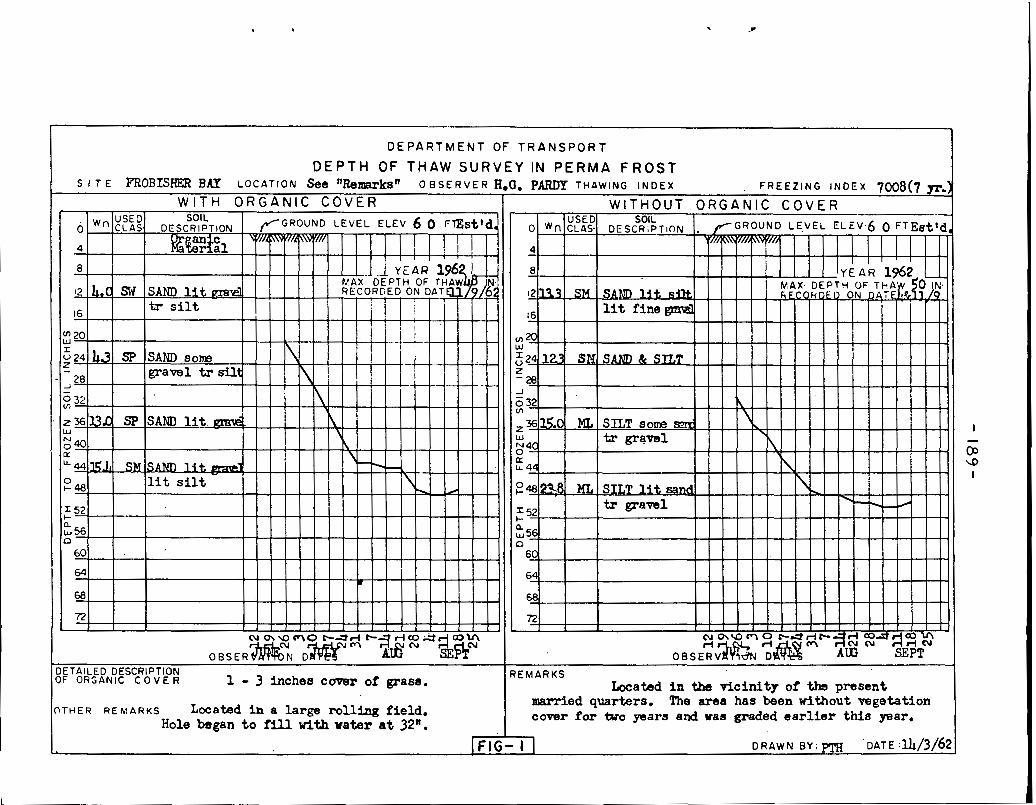
I T H E R R E M A R K S Located i n a large rollFng f i e l d . Hole began t o fill with water a t 32".
married quarters. The area has been without vegetation cover f o r tuo p a r s and was graded earlier this p a r .
IFIG- I I D R A W N B Y : ~ T H 'DATE :14/3/62

I DEPARTMENT O F TRANSPORT
I I BUI L D I NG SURVEY I N PERMAFROST
STRUCTURE -Z1&-~2--%!%&!2~.! -------- ---- USED AS -m-r&-~r-%-~~_d_-&&b,----------- Dl MENSIONS ---- 4Lk&J ------------------ ---
COMPLETION DATE ----- JS-6, ----- -------- STRUCTURE HEATED OR U N H E A T E D - - - & % ~ ~ ~ ~ ~ ,
0 AVERAGE INSIDE TEMPERATURE ----a ------- PERFORMANCE OF STRUCTURE -H_a_s- -~~~kd- FLOOR MOVEMENT MAXIMUM--^^' ,-,,,-- (SETTLING OR H E A V ~ ~ G )
AVERAGE --I-I- -em---
FOUNDATION MOVE MEN^, MAXIMUM -l~'~------- (SETTLING OR HEAVING) II
AVERAGE -2 ---,,,,,-
@CATION PLAY (Indicate Location of Worst Conditions
S e t t l e d -4" on
o u t e r sills
Estimated Ice SUBSOl L DEPTH US ED CLASS AV.MOlSTURE % Lensing %by Vol.
C L l MATOLOGICAL DATA AVERAGE ANNUAL TEMPERATURE ------------ OF

COMPRESSlVE STRENGTH OF PERMAFROST SOILS
1 6(
14(
1 2C
IOC
80
60
40
20
0.
TEMPERATURE OF
l a t a from ?'~undamentals of Frozen Soil ~ c c h a n l c s ' ~ b TSYTOVICH 8 S U M G l N o f MOSCOW - LENINGRAD ACADEMY o f S C ~ E N C E S U S S R 1937

CONSOLIDATION CHARACTERISTICS
OF
PERMAFROST (In the frozen and thawed . state)
P II II PRESSURE p
Data From : THE LENINGRAD ENGINEERING CONSTRUCTION INSTITUTE
F IG - 4

GRANULAR NON FROST SUSCEPTIBLE SUBGRADE @ D.0.T Spec. C4-7
NORMAN WELLS N*W.T0 0 . 0 . ~ Spec. ~ 4 - 3
FIG- 5 A
CRUSHER RUN
@ - D.0.T. Spec. C 4 - @8 @ Special D.0.T. Spec.
I N U V I K N - W - T FIG - 58

THICKNESS OF BASE REQUIRED TO PREVENT THAWING OF SUBGRADE
NOTE: CURVE IS FOR 5 % MOISTURE CONTENT IN BASE. FOR OTHER VALUES OF MOISTURE CONTENT,
' MULTIPLY THICKNESS SHOWN BY - FOLLOWING VALUES.
2 1.40 6%, 0.95 3%, 1.19 0.87 40; 1 .08 e O/O, 0.80
THAWING INDEX OF SURFACE
from: ENGINEER MANUAL MILITARY CONSTRUCTION US OF ENGINEER PART 15 CHAPTER 3 . .
CORPS
FIG- 6

-195-
RUNWAY CONSTRUCTION IN PERMAFROST POSITION OF THE FROST LINE (MAXIMUM DEPTH OF THAW)
BEFORE AND AFTER CONSTRUCTION
THAWING INDEX FREEZING INDEX
10 YR. AVERAGE 2252 MAX. 2 8 4 6 M I N 1757
10 YR. AVERAGE 8 0 2 9 MAX. 8 5 8 1 MIN. 6811
FINISHED
4 ,,
SC, M L - CL
FINISHED
w
FINISHED
F l L L (Granular non frost susc.)
FROZEN FlLL ICE LENSES:-
LARGE LENSES REPORTED ON EAST SIDE .IN ML-CL SOIL, IN GENERAL FINE OR SMALL- , NATURAL SUBGRADE SOIL
, . FROZEN SUBGRADE SOIL
. FIG. -?

I 1'-3' COMPACTED GRAVEL PAD
GRAVEL PAD FOUNDATION I N PERMAFROST USING MUD S I L L
FIG - 8
- 1 2 ' ~ i n , . Removeable Plywood Panel
I COMPACTED G R A V E L PAD
,Original Ground - G R A V E L PAD FOUNDATION
IN PERMAFROST USING ADJUSTABLE JACKS F IG - 9

I 3' 0"
I C O M P A C T E D G R A V E L P A D
,Oriainal Ground
G R A V E L PAD FOUNDATION I N PERMAFROS+T
USING CONCRETE PEDESTAL

IFOUNDATION ON ROCK I N PERMAFROST AREA ( EXCAVATION OF THE ACTIVE ZONE AND BACKFILL BY GRANULAR MATERIAL )
. . . . . : . . . . . : 1%
.... . . . . . . . . .... . .z! . . . . . . . . . ':xu 'Y"
ALL FOOTINOS TO BEAR ON T H E BROWN GREY SlLT STONE ALLOWABLE BEARINO VALUE FOR FOOTINGS O N T O P O F HARD BROWN GREY S l L T STDN TO B E 2 TONS /SO. FT.
NORMAN WELLS MA1 NTENANCE, G A R A G E FOUNDAT l ON
FIG.- I I


A C T I V E L A Y E R
P E R M A F R O S T 8*@ or 8' x 8' Fir o r C e d o r Pi les
0 = D e p t h of A c t i v e L a y e r

FORCES ACT1 NG ON MAST FOUNDATION
AND ANCHORS
Ground
Anchor Foundation P i e r
F I G - 14

FIG- 15A

METAL PLATE
11 i~ II II
Pile - 8"4 Perrna f rost or 8"%8"$
FIG - 16

- + Permafrost
FIG - I?

4 S p a c e r s ' t o suit R Connection i n accordance \ with mast Manufacturer's detai ls
To suit design angle d of guy wires - ~ a x , 6 ' - 0 "
. r
2 Channel Beams - back to bac . .
ACT IVE ZONE
P E R M A F R O S T
- S t r u c t u r a l Grade Wood P i l es Al ternat ive : Hollow Steel
Pipe P i les
'Pile should b e f rozen into ground, i n advance of e rec t ion .
F IG - I8
Shear Plates,
/
- Douglas Fir Piles - To Suit
Mast
Permafrost J L ine ----

Recover working a r e a with l o c a l organic
A C T I V E
ZONE
12' D i a . I' p late to b e welded to 5 'p ipe .
P E R M A F R O S T I
F I G - 19
Fil l with grease and c a p
Original Ground
Course to fine gravel bockfill containing not
?:I 7 5 " ~ i a . extra strong pipe
I