#39 - university of calgary in alberta
TRANSCRIPT


=SUE #39
- ----
mPORT ON SUBSURFACE SOIL CONDITIONS
FOR PROPOSED SALINE: RIVER BRIDGE ’
MILE 521 MACKENZIE HIGHWAY NORTHWEST TERRITORIES
Prepared by
Underwood McJ&llan & Associates Limited C o n s u l t i n g Professional Engineers

2106-032-45 , I ~ , ~ ' . , ,
A p r i l 18, 1973
Department of Public Works P. O. Box 488 EDMONTON, Alberta.
ATTENTION: Mr. F, E. Kimball
Dear S i r :
Re: Subsurface Soil Investigation Proposed Sal ine River Bridge Mile 521, Mackenzie Hiqhway.
Attached please find our report on the subsoil and foundation conditions for the proposed S a l i n e Ri.ver bridge at mile 521 on the Mackenzie Highway, in the Norkhwesk Territories.
If you have any questions concern ing the con ten t s of this report , we would be pleased to d i s c u s s them with you at your convenience.
Yours very t r u l y ,
UNDERWOOD McLELLAN & ASSOCIATES LIMITED
Per: D. G. Pennell, Ph.D. P. Eng.
DGP/rr
Encl .
4
. .

TABLE OF CONTENTS
Paqe No' S.
A. INTRODUCTION 1 - 2
B. FIELD AND LABORATORY INVESTIGATION 3 - 6
C. SITE AND SUBSOIL CONDITIONS 7 - 10
D. CONCLUSIONS AND RECO"F,NDATIONS 11 - 24
1. Pier and Abutment Foundation
2. Lateral Abutment Loads
3 . Bridge Approach Grades and Embankments

f 1 8 1 I I I I .I
APPENDIX
Explanation of F i e l d and Laboratory Data Pages 1 - 6 Plate 1
Plate 2
Plate 3
Plate 4 - -13
Plate 14 - 19
c
Mosaic and Test Hole Location Plan.
Bridge S i t e Prof i l e and Soil Cross- Section.
Photographs of Bridge Crossing
Centreline and Structure Test Hole Logs.
Borrow P i t Test Hole Logs.

A. INTRODUCTION
The subsoil investigation undertaken at the Sal ine
River forms part of the overall geotechnical investi-
g a t i o n which was conducted from mile 450 t o 550 on
the Mackenzie Highway for the Department of Public
Works, Government of Canada.
It was the intention of the present investigation
to determine the ver t i ca l sub’soil material sequence,
physical and structural proper . t ies , permafrost
c o n d i t i o n s and groundwater conditions which would
be expected to influence the stability of the valley
slopes and embankments and the design and construc-
tion of the bridge foundation.
The included conclusions and recommendations have
been based upon exploration and sample acquisition
operations conducted at 10 positions adjacent to
and along the proposed bridge centreline in the
river channel and slopes of the bridge approaches.
- 1 -

In the formulation of conclusions and recommendations,
the consistency and composition of the subsoil
materials between and in the proximity to the
indiv idual test boring positions has been assumed,
but not veri f ied .
4
- 2 -
c
8 1 I
B. FIELD AND LABORATORY INVESTIGATION
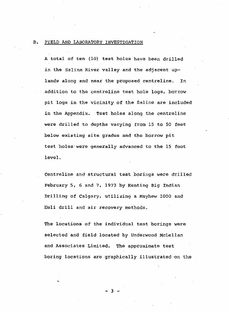
A t o t a l of t e n (10) test holes have been d r i l l e d
in the S a l i n e River v a l l e y and the adjacent up-
lands along and near the proposed centre l ine . In
addition to the centre l ine test hole logs, borrow
p i t logs in the v i c i n i t y of the S a l i n e are included
in the Appendix. Test holes along the centre l ine
were drilled to depths vary ing from 15 to 50 feet
below e x i s t i n g s i te grades arid the borrow pit
test holes*were generally advanced to the 15 foot
level.
Centreline and structural test borings were d r i l l e d
February 5, 6 and 7, 1973 by Kenting Big Indian
D r i l l i n g of Calgary, utilizing a Mayhew 1000 and
Heli drill and a i r recovery methods.
The l aca t ions of the individual test borings were
selected and f i e l d located by Underwood McLellan
and Associates L i m i t e d . The approximate test
boring l oca t ions are graphical ly illustrated 'on the
I I
- 3 -

accompanying mosaic and t e s t hole location plan.
All variations of s o i l , permafrost and groundwater
conditions encountered during the test boring
operations were noted, and representative samples
of the ex i s t ing subsoils were taken, The majority
of samples were disturbed having been obtained by
the air recovery method. Sampling and f i e l d t e s t i n g
were also undertaken with a two inch O.D. split
spoon sampling tube and solid penetrometer.
In the laboratory the samples of materials derived
from the drilling operation were subjected to
standard laboratory classification procedures
i n c l u d i n g particle s i z e distribution and Atterberg
index property determinations. Moisture contents
were obtained for a l l samples returned to the
laboratory. Whenever a suff ic ient l eng th of intact
sample was retained in the penetrometer tube, both
wet and dry densities were obtained.
Permafrost samples were classif ied according'to

"
Field Descr ip t ion of Permafrost". The excess ice
content of permafrost samples was determined by
v i s u a l i n s p e c t i o n and by measured thicknesses of
ice l e n s e s . The calculation of excess ice content
was performed by the division of the îce t h i c k n e s s
by the total sample thickness.
A l l s o i l samples were classified according to the
Unif ied Soil Classification System.
The results of a l l laboratory and f i e l d t e s t s are
summarized in the Appendix on the test hole logs.
Test holes have been des ignated by mi leage , type
and number. Examples include 521B 364A, 521s 352A
and 521C 469B. The l e t te r syrribols and numbers
i n d i c a t e :
521 - mileage.
E, S, C - between mileage and test hole numbers,
indicate borrow, centreline and struc-
ture test holes, respectively.
364, 352, 469 - test hole numbers.
- 5 -

I
...
A , B - af te r test hole numbers indicate d r i l l i n g
performed by Mayhew 1000 or Heli drill,
respectively.
c
- 6 -
C.
I 8 I 1 I I
S I T E AND SUBSOIL CONDITIONS
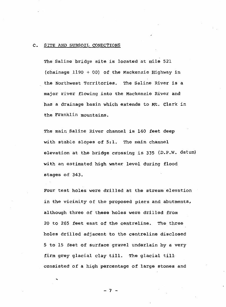
The S a l i n e bridge site is located at mile 521
(chainage 1190 + 0 0 ) of the Mackenzie Highway in
the Northwest Territories. The Saline River is a
major river flawing into the Mackenzie River and
has a drainage basin which extends to Mt. Clark in
the Franklin mountains.
The main Saline River channel is 140 feet deep
with stable slopes of 5:l. The main channel
elevation at the bridge crossing is 335 (D.P.W. datum)
w i t h an estimated high water level during flood
stages of 3 4 3 .
Four test holes were drilled at the stream e l e v a t i o n
i n the vicinity of the proposed piers and abutments,
although three of these holes were drilled from
20 to 265 feet east of the centreline. The three
holes drilled adjacent to the centreline disclosed
5 to 15 feet of surface gravel underlain by a very
firm grey glacial clay till. The glacial till.
consisted of a high percentage of large stones and
c
- 7 -

c
i t s very firm t o s t i f f c o n s i s t e n c y was i n d i c a t e d
by the s o l i d penetrometer blow counts from 26 t o 8 3 .
Some d i f f i c u l t y was experienced i n i d e n t i f y i n g t h e
soil s trata i n tes t h o l e 355A as a r e s u l t of caving
but i t has b e e n c l a s s i f i e d as gravel with some clay,
Large b o u l d e r s e x i s t a t the surface b u t at g r e a t e r ,
depths large boulders were not encountered. This
test hole, 35511 was d r i l l e d a t the north abutment
l o c a t i o n and the sol id penetrometer blow counts of
4 2 t o 53 i n d i c a t e the dense nature of the s trata .
The moisture content of both the g l a c i a l boulder
clay till and gravel was low averaging 7% t o 8%
throughout the depth of t h e test holes. All four
test holes indicated non-permafrost conditions t o
t h e lowest e l e v a t i o n of 310 which was a t t a i n e d
during drilling operat ions. The glac ia l till i s
likely t o be of Ple is tocene origin w i t h t h e stream
gravel having been depos i t ed s ince g l ac i a t ion .
Test holes 356A and 357A drilled on the north
approach slopes indicated dry frozen gravel and
dense g l a c i a l c l a y till with moisture con ten t s of
*
- 8 -

d
4% and 8% respectively. Test hole 469B near the
top of the slope disclosed unfrozen glacial till
with an average moisture content of 10 percent .
Two river terraces on the south approach, investi-
gated with test holes 341A and 350A indicated 4 to
7 feet of gravel over clay till. The moisture
content of the c lay till was approximately 20% and
exhibited a dry u n i t weight of 106.3 pcf. All
materials on the south slope were frozen w i t h some
random ice. Although the moisture contents of the
frozen till is relatively low, it is 10% greater
than the unfrozen till found i n tes t hole 469B on
the nor th slope. On the valley slopes the maximum
peat depth was four inches.
Free water was not encountered i n the test holes and
no s i g n i f i c a n t sloughing occurred during a i r - d r i l l i n g .
Bedrock materials were not encountered during
drilling at the Saline River crossing although
Cretaceous sandstones and shales wi th interbedded
coal would be expected.

.-.
A s o i l p r o f i l e with plotted test hole logs of
the bridge valley site is included in the
Appendix.
- 10 -

D. CONCLUSIONS AND RECOMMENDATIONS
On the basis of the present inves t iga t ion , we
wish t o offer the following general ized conclusions
and recommendations r e l a t i v e to the design and
construction of the proposed Saline River bridge
foundation and approaches.
1. Pier and Abutment Foundation Desiqn
The gravel and g l a c i a l till deposits which were
described in the previous . sect ion will form
the bearing s t r a t a for the proposed bridge
piers and abutments. The two foundation types
which may be considered include a spread
footing or pile system.
Pier bases should be placed at approximately
elevation 325 i n the .dense glacial c l a y till
and the allowable foot ing bearing capacity
would be 6000 psf in this material, In order
to a t t a i n the elevation of the glacial till
approximately 10 feet of overburden gravel
must be removed.

Although a footing type foundation may be
employed at t h i s site, driven p i l e s are preferred.
The p i l e types available i nc lude timber, pre-
cast concrete, steel H-piles and pipe piles.
Timber pi les may be utilized but t i p protection
would be necessary t o drive through the gravel
strata into the glac ia l till. Timber p i l e s
driven to l trefusal l l would a t t a i n allowable load
bearing capacit ies near 40 tons but t h i s would
depend upon t h e p i l e size and energy r a t ing of
the pile driving hamer. The timber piles
would be expected to attain "refusal" at a
depth of approximately 15 f e e t from the surface.
The pre-cast concrete piles may be utilized
but s p l i c i n g is d i f f i c u l t although a t t h i s site
the "refusal" depth w i l l be in the range of
15 to 20 feet below e x i s t i n g channel grades,
u n l e s s s i g n i f i c a n t var iat ions i n the soil profile
exist across the stream channel.
Steel H-piles or pipe piles are recommended
c
- 12 -

d
for consideration based upon high driving
strength, high load capacity and ease in
s p l i c i n g and c u t t i n g . Àt the S a l i n e River site,
the steel pipe or H-piles w i l l meet refusal
in the dense till at approximately the 30 foot
level and the allowable capacities w i l l be in
the range of 80 tons. The capacity w i l l depend
upon the structural shape and material as well
as the t i p protector utilized. wherever
lirefusalt1 i s not atta ined in the g lac ia l till
or gravel depos i t s , the capacity of the p i l e
may be' estimated on the basis of the skin
f r i c t ion between the s o i l strata and pile.
Approximate allowable capacities for long steel
f r i c t ion piles may be determined by using
allowable unit adhesion of 600 p s f in the
dense g lac ia l clay till and 800 p s f in the
gravel s t r a t a . In order t o a t t a i n penetration
of the steel p i l e s around large boulders, it
may be necessary to u t i l i z e vibration techniques.
- 13 -

...
It is recommended that a l l piles be driven t o
t trefusal*8 . "Refusal" will depend upon the
e n e r g y r a t i n g of the hammer b u t is commonly
15,000 f t . lb. As an i n i t i a l guide, piles
should be d r iven t o blow counts of 180 blows/ft .
or 15 blows/inch. The p i l e c a p a c i t y is largely ,
a function of the amount of energy expended in
i n s t a l l i n g the p i l e and not j u s t of the recorded
resistances. The pile which is dr iven t o a
s u s t a i n e d r e s i s t a n c e will perform better than
one which is terminated the i n s t a n t a given
r e s i s t a n c e is a t t a i n e d . O f course, the p i le
must not be driven u n t i l damage occurs and
whenever resistance i n c r e a s e s g r e a t l y , the
driv ing should be terminated.
The c a p a c i t y of a p i l e should be established in
the f i e l d by s e v e r a l p i l e - d r i v i n g tests. The
u l t i m a t e c a p a c i t y would be c a l c u l a t e d on the
basis of a dynamic pile driving formulae such
as the Hiley, Danish or Weisbach. It is a
recommended that the Engineering News formula
9
- 14 -

not be utilized as a result of i t s extreme
variation in fac tor of safe,ty.
It is further recommended that s t a t i c load
tests be performed to establish more accurately
the bearing capacity of a typical pile and the
applicability of dynamic pile formulae fo r
predicting pile capacity. It is emphasized
tha t load t e s t s at t h i s site are important t o
establish p i l e capacity as d r i v i n g formulae
can on ly be considered a rough guide for piles
in cohesive till soils.
The lateral resistance of p i l e s can be estab-
lished by recently developed methods based on
beam on elastic foundation methods but the
simple and more conventional approach is based
on calculation of the Rankine passive earth
pressure against the p i l e . Us ing Rankine
theory the ultimate pass ive resistance force/ft.
of p i l e can be obtained by P = 4 rbKpH . The
submerged unit weight of the g rave l and till
2
- 15 -

I
material may be taken as 60 pcf and the passive
pressure c o e f f i c i e n t K as 3.0. In order to P es t ab l i sh the allowable l a t e r a l load a factor
of safety of 2.5 should be applied to the above
ultimate load. Generally, the lateral load on
deep piles tends to exceed the passive resist-
ance, consequently, the above simplified
approach is on the conservative side,
Whenever the deep embankments are constructed
of compacted g r a n u l a r f i l l as outlined and
.recommended i n section D3, the abutments may
be placed on spread foot ings in the f i l l . The
allowable bearing pressure for the abutments
will depend upon the characteristics of the
f i l l material utilized but fo r i n i t i a l design,
4000 psf may be used assuming a coarse compacted
gravel is used. If i n f e r i o r material or
compaction techniques are utilized in the
embankment, the abutment must be carried on
piles into the i n s i t u granular subsoils below
the creek channel. Piles must be designed to c
- 16 -
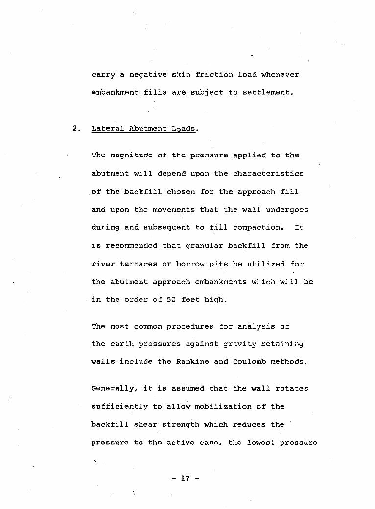
I I I 1 carry a negat ive s k i n f r i c t i o n load whenever
embankment f i l ls are s u b j e c t t o settlement.
2. Lateral Abutment Loads.
The magnitude of the pressure appl ied t o the
abutment w i l l depend upon the c h a r a c t e r i s t i c s
of t h e b a c k f i l l chosen for the approach f i l l
and upon the movements tha t the wall undergoes
during and subsequent t o f i l l compaction, It
is Secommended that granular b a c k f i l l from the
river terraces or borrow p i t s be u t i l i z e d for
the abutment approach embankments which will be
i n the order of 50 f e e t high.
The most common pracedures for a n a l y s i s of
the ear th pressures a g a i n s t gravity r e t a i n i n g
walls include the Rankine and Coulomb methods.
Generally, i t is assumed t ha t the wall rotates
s u f f i c i e n t l y t o allow mobilization of the
backfill shear strength which reduces the
pressure t o the active case, the lowest pressure
r.
- 17 -

I
tha t can be-realized. This assumption applies
reasonably accurately when the backfill consists
of 'uncompacted granular material but pressures
greater than the a c t i v e occur wherever compaction
of the backfill is undertaken.
While the total y ie ld a t different e levat ions
on the abutment may be adequate for mobilization
of the f u l l backfill strength, a gradual build-
up of the backfill also results in a gradual
yielding of the w a l l . Therefore, by the time
the backf i 1 X is complete only a fraction of
the total y i e l d of the wall has become effective
in decreasing the earth pressure, Recent studies
have indicated that the actual earth pressure
magnitude will exceed the a c t i v e case and may
approach the earth pressure at-rest. Pressures
greater than the at-rest case may occur i f
heavy equipment is utilized near the concrete
abutment.
If the Coulomb approach is u t i l i z e d , the angle
- 18 -

I 1
I I I I 1 I I 1 1 I 1 I I I
...
of wal l friction between concrete and c o a r s e
sand and gravel would be 20 degrees. The
angle of i n t e r n a l f r i c t i o n for compacted
granular m a t e r i a l would be approximately 38
degrees and the dry d e n s i t y may be t aken as 115
pcf . For a simple verticle r e t a i n i n g wall
abutment w i t h h o r i z o n t a l backfill the Coulomb
active c o e f f i c i e n t would be .24 and the at-rest
c o - e f f i c i e n t based on KO = 1 - sin @ would be
. 3 8 . The pressure d i s t r i b u t i o n b e h i n d a gravity
r e t a i n i n g wall h a s been shown to be non-triangular,
but as a first approximation and for simplici ty ,
the triangular p r e s s u r e diagram i s recommended.
It is also recommended tha t whenever backfill is
compacted in l i f ts by v i b r a t o r y compactors the
at-rest c o e f f i c i e n t be utilized for c a l c u l a t i o n
of the u l t i m a t e earth pressure.
If a p i l e f o u n d a t i o n is used for the abutments
i t is recommended that some batter piles be
u t i l i z e d t o ensu re adequate l a te ra l support
against earth pressures. The l a t e r a l resistance
k
- 19 -
I I I
&
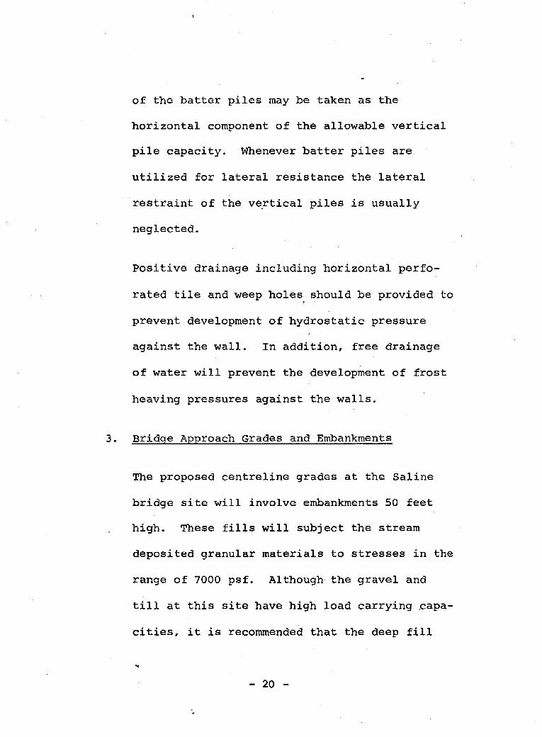
of t h e b a t t e r p i l e s may be taken as the
horizontal component of the allowable v e r t i c a l
p i l e c a p a c i t y . Whenever b a t t e r p i l e s a r e
u t i l i z e d f o r l a t e r a l resistance t h e l a t e r a l
res t ra int of the ve.r t ica1 p i l e s is usually
neglected.
Positive drainage including hor i zon ta l pe r fo -
ra ted t i l e and weep holes should be provided t o
prevent development of hydrostatic pressure
against t h e wall. In addition, free drainage
of water w i l l prevent the development of frost
heaving pressures against the walls.
3 . Br idqe Approach Grades and Embankments
The proposed centrel ine grades a t the Saline
br idge s i te will involve embankments 50 feet
high. These f i l l s will subject t h e stream
deposited granu la r ma te r i a l s t o stresses i n t h e
range of 7000 p s f . Although the gravel and
till a t t h i s s i te have high load carrying sapa-
cities, it is recommended t h a t the deep fill
- 20 -

1 I I I
k
be placed seve ra l months p r io r t o foundation
cons t ruc t ion . I t is also recommended t h a t
the embankments be placed in two s t a g e s of
25 feet each t o allow conso l ida t ion and
s t r e n g t h inc rease in unfrozen surface strata
on t h e v a l l e y slopes which may have not been
subjected to high preconsol ida t ion . The
proposed fill varying from 35 t o 50 feet i n
depth w i l l extend 1500 feet across the v a l l e y
and w i l l cover unfrozen and f rozen soils. It
can be expected t h a t these deep f i l ls w i l l .
not al low thawing of the north-facing slopes and
s t ab i l i t y w i l l therefore be maintained.
Embankment granular slopes should be compacted
at 2:l slopes which would al low a factor of
safety o f 1.5 assuming the mater ia l possesses
zero cohesion. If t h e slopes are comprised of
compacted unfrozen glac ia l till the s i d e slopes
should be increased to 2$:1.
It is recommended t h a t granular fill be compacted
c
- 21 -

I I 1 I I I I
at all deep approach fills to 95% of Standard
Proctor density u t i l i z i n g vibratory compaction
and g lac ia l till should be compacted with
sheepsfoot rollers. Although construction may
be performed during the w i n t e r , the d r y na tu re
of the granular materials will allow satis-
factory compaction. It is emphasized that
compaction of these deep approach f i l l s is
mandatory to ensure slope stability and prevent
settlements at the bridge approach.
Common excavation will not be available from
the bridge site valley slopes as the grade
line has been proposed mainly t o produce fill
sections. Some granular embankment i s avail-
able throughout the river terraces but its
utilization as a construction material may be
prohibited by land use regulations. The
volume of fill required will necessitate the
utilization of borrow material. On the up-
lands, two borrow p i t s were investigated which
- 22 -

I
...
contained 3 to 7 feet of gravel overlying
clay. It is doubtful that s u f f i c i e n t granular
fill can be located above the river valley,
therefore, pits should be developed along the
river terraces.
Although the roadway gradeline through the
Salil ie val ley w i l l primarily produce f i l l
sections, a 15 foot cut is proposed a t stat ion
1207 + O0 on the south slope. This cut will
be undertaken in 4 feet of gravel and 11 feet
of f rozen glac ia l c lay till. Another cut of
30 foot depth at s t a t i o n 1177 =k O0 on the nor th
slope will be undertaken in a f rozen high
densi ty gravel and clay mixture. U t i l i z a t i o n
of backslopes of 2 : l ensure overall stability
of both cuts but some surface aggradation can
be expected as a new active layer is established.
A f t e r excavation of the cuts the roadway subgrade
w i l l consist of frozen glac ia l till. An active
layer w i l l be established but thaw settlement
- 23 -

I
c
will be minor for t h i s material as a result
of its high bulk dens i ty .
Some d i t ch drainage control will be necessary
to re tard erosion effects on the steep cut
grades.
ï
- 24 -
APPENDIX >
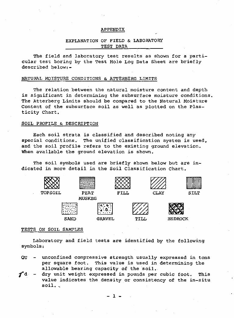
EXPLANATION OF FIELD & LABORATORY TEST DATA
The f i e l d and laboratory tes t resul ts a s shown f o r a part i - cular tes t boring by t h e Test Hole Log Data Sheet are b r i e f l y described below:-
NATURAL MOISTURE CONDITIONS & ATTERBERG LIMITS
T h e r e l a t i o n between the na tu ra l mo i s tu re content and depth i s s ign i f i can t i n de t e rmin ing t he subsu r face mo i s tu re cond i t ions . The Atterberg L i m i t s should be compared t o the Natural Moisture Content of the subsurface s o i l as w e l l as p l o t t e d on t h e Plas- t i c i t y C h a r t .
SOIL PROFILE & DESCRTPTION
E a c h s o i l s t r a t a i s c l a s s i f i e d and described noting any spec ia l cond i t ions . The u n i f i e d c l a s s i f i c a t i o n system is u s e d , and t h e s o i l p r o f i l e r e f e r s t o the ex is t ing g round e leva t ion . When a v a i l a b l e the ground e levat ion is shown.
The s o i l symbols used a r e b r i e f l y shown below b u t are i n - dicated i n more detail i n t h e S o i l Classification Chart.
TOPSOIL PEAT FILL SILT MUSKEG
SAND GRAVEL TILL BEDROCK
TESTS ON SOIL SAMPLES
Laboratory and f i e l d tests are i den t i f i ed by t h e following symbols :
QU - unconfined compressive s t r e n g t h u s u a l l y expressed i n tons per square foot. This value is used i n determihing the a l lowable bear ing capac i ty of t h e . s o i l .
f d - dry unit weight expressed i n pounds per cubic foot. T h i s v a l u e i n d i c a t e s t h e d e n s i t y op cons is tency of the i n - s i t u s o i l .
- 1 -

I i I 1 I 1
C -
M.A. -
SO4 -
N 3
Consoliddtion test. These t e s t results are separately enclosed and provide information on the consolidation or settlement properties of the soil strata. grain s i z e analysis. These test results are separately enclosed and indicate the gradation properties of the material tested. water soluble sulphate content is conducted primarily to determine whether sulphate resistant cement is required f o r the foundation structure. standard penetration f i e l d t e s t . This test is conducted in the field t o determine the in-situ consistency of a so i l strata. The "N" value recorded is the number of blows from a 140 lb. hammer dropped 30 inches (free f a l l ) which are required to d r i v e a 2" O . D . Raymond type sampler 12 inches into the soil.
The resistance and unconfined compressive st rength of a cohesive soil can be related to its consistency as follows:-
N - BLOWS/Ft. CONSISTENCY QU - T/Ft.2 2 very soft 0.25
2 -4 4-8 8-15
~ 15-30
O. 25-0.50 ' O. 50-1.00 1.00-2.00 2.00-4.00
s o f t medium or firm stiff very stiff
I 30 I 4.00 I hard The resistance of a non-cohesive soil (sand) can be related to
4 i ts consistency as follows:-
O 5 10 15 20 WIDTH B OF FOOTING IN FEET
- 2 -

I
SAMPLE CONDITION AND TYPE
The depth and condition of samples are indicated by
the following symbols :
d
UNDISTURBED DISTURBED LOST SAMPLE
SAMPLE TYPES
U D.S. M R.C.
3" O.D. Shelby tube sample drive sample moisture content sample rock core sample
I
PERCENTAGE WATER SOLUl3TtX SULPHATE CONCENTRATION
O 0.1 0.2 0.3 0 .4 0.; 0 . 6 O. 7%
Alegli- Posi- g i b l c t i v e Considerable Severe
1
RELATIVE DEGREE OF SULPHATE ATTACK ?
Negligible - Normal Portland Cement may be used.
Positive - Normal Portland Cement may be used, provided
the s t r eng th of the concrete is increased up to 500 psi
higher than t h e compressive s t r eng th which would nor-
mally be used.
Considerable - Type V cement must be used and the con-
crete compressive strength should be increased to.500
4 - 3 -

I
psi higher than the compressive s t r e n g t h Which would
normally be used.
Severe - Type V cement must be used and t he concrete
compressive s t r e n g t h should be increased from SO0 to
1000 psi h ighe r than t h e compressive strength which
would normally be used.
GROUND WATER TABLE
The water table is indicated by the l e v e l of standing
water in a test boring a f t e r equilibrium has been reached.
This is general ly taken 24 hours after the drilling oper-
ation. The water table is usually an i nc l ined surface
t h a t is dynamic in nature with its highest level late .-
in the winter or early spring gradually f a l l i n g through-
out the summer,
4 - 4 -

UNIFIED SOIL CLASSIFICATION SYSTEM
" I I
PLASTICITY CHART
LIQUID LIMIT- WL FOR LABORATORY CLASSIFICAMN OF FINE-BRAINED SOILS
-5- UNDERWOOD MeLELLAN 4 ASSOCIATES LIMITED

NATIONAL RESEARCH COUNCIL PERMAFROST CLASSIFICATION SYSTEM
Permafrost ground ice occurs i n three basic c o n d i t i o n s
including non-visible, v i s ib le (less than one inch i n
thickness) and clear ice.
A. N o n - v i s i b l e - N
Nf - poorly bonded or friable frozen so i l
Nb, - Well bonded Soil, no excess ice
Nb, - well bonded soil, excess ice
B. Visible - V (less than 1" thick)
Vx - i n d i v i d u a l ice crystals or inclusions
VC - ice c o a t i n g s on particles
vr - random or irregularly oriented ice formations
V, - stratif ied or or ien ted ice formations
C, Visible Ice - (greater than 1" thick)
Ice - ice with so i l inclusions
Ice + Soil - ice without soil i n c l u s i o n s .
A more complete d e s c r i p t i o n of t h i s system is included in
NRC publication TM 79.
-6-


I t ! I I l l !
I
! ! I'
I 1
!
1 'I
I
l !
'!
"..II_
i
, .!

I I I I I I I
Plate 3 .

.. .
i in
z
t3
I I IT, m
I
s
L t t .t 1

8
10
12
14
16
t3
20
22
24 "
F I I
#SCRIPTION ICE
Yr.
Vr.
V I
I
I
CANADA
REMARKS

, . . . . , .
r! v)
O
.
IOB
rlA$
110s 03lJIN
n
11
01
1V
M1
3N
~d
33N
V15153M
A113403311 *A
IdAl
JldllW
C
"
I

:CH
W E T
DESCRlPTlON ICE I-

c 1
"" ". - - -. " " "" """""
U N O E R G " 0 0 MctELLAN & ASSOCI AT DEPARTMENT OF weuc WORKS, CANADA h4ACKENZIE HIGHWAY
SOIL DESCRlPTlON
JRFACE DRAINAGE:

I c -.I
n w

I I I
- . . . . .
. .
-"i
""
. .
I
a

4
2
Q
5 w
e

E Il
. .
SOIL DESCRIPTION
77.L L
[GRAIN- - ?E
1 4
" "-
i

SOIL DESCRIPTION
4 j -u 3 : i
c
! i
!
i
i i i I I
' I f i
I l I
I
= I
L
I 1
I !
i
1
I l t
I . L

! ! i ! l I ! i ! 1
I J
I a

'O NO:
7 ESCRIPTION
ICE
i t

t - 1- I
i X
I
t hL1 r
Yo %
1
i
TEST HOLE
AEMAFXS

w
n

t '
SOfL oEsCRlPlroN
I I
Ebfb . Of t
3ESCRIPTION ICE
REMPCKS

S O L OLSCRlPilON
MUSKCk
CLa.l
I
TO E DRAINAGE:
>ESCRIPTION IC€
CANADA
TEST HOLE
REMORKS