hdd training curriculum 2014 dw 01
TRANSCRIPT
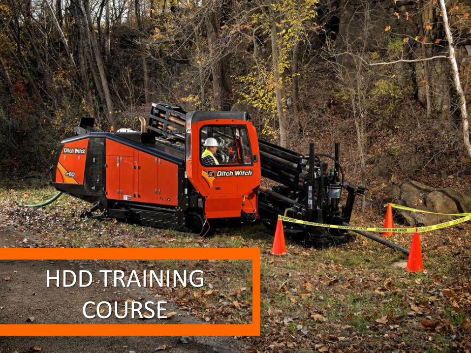
HDD TRAINING COURSE
WELCOME
Agenda
Breaks
Phones
Handouts
Support
Why We Are Here?
Show Gas Hit Video

HDD Safety
Preparations
Emergency Procedures
Electrical Strike
Exposed Drill Rod
Open Pit Danger
Transporting
Communication
Show the HDD Advantage Video

Directly out of Operator manual
PREPARATIONS

Directly out of Operator manual
IT’S ALL ABOUT HABITS

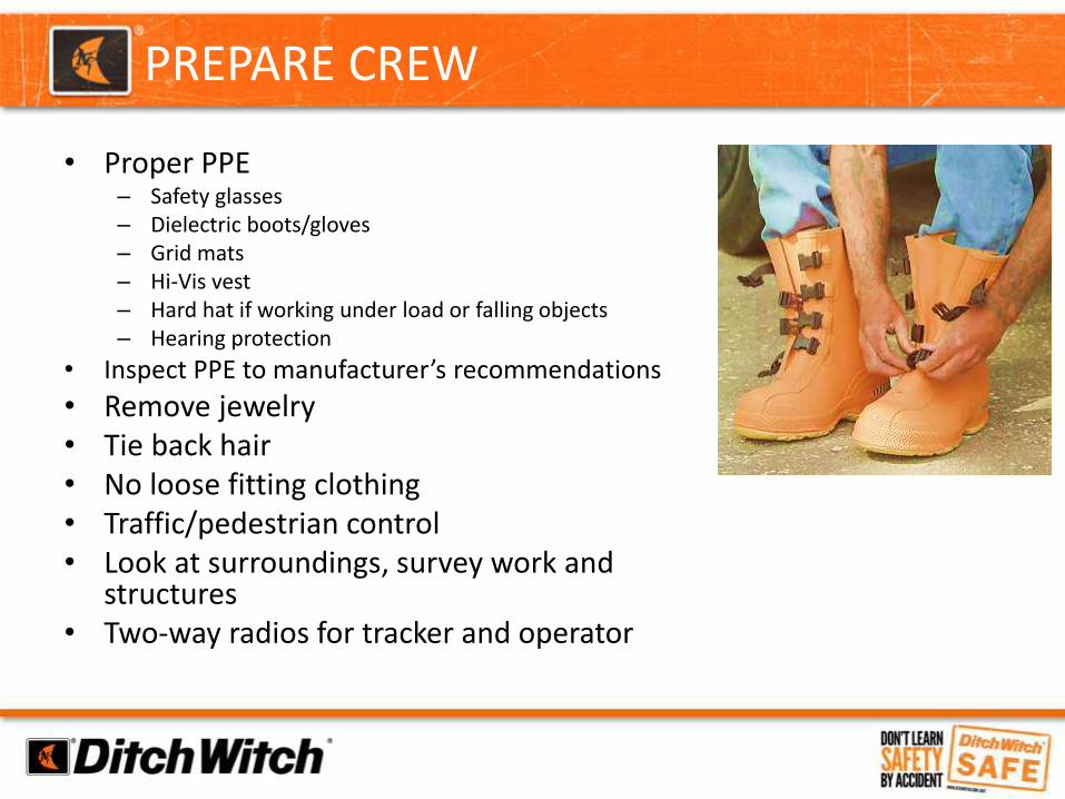
• Proper PPE– Safety glasses– Dielectric boots/gloves– Grid mats– Hi-Vis vest– Hard hat if working under load or falling objects– Hearing protection
• Inspect PPE to manufacturer’s recommendations
• Remove jewelry• Tie back hair• No loose fitting clothing• Traffic/pedestrian control• Look at surroundings, survey work and
structures• Two-way radios for tracker and operator
PREPARE CREW
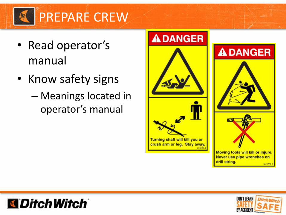
• Read operator’s manual
• Know safety signs
– Meanings located in operator’s manual
PREPARE CREW

• An emergency response plan should be created and communicated to entire crew in the case of an underground strike and/or jobsite injury– Plan should include:
• contacts with phone numbers
• procedures for each type of event
• assignments of responsibilities
• exit route(s) if necessary
• meeting place
PREPARE CREW
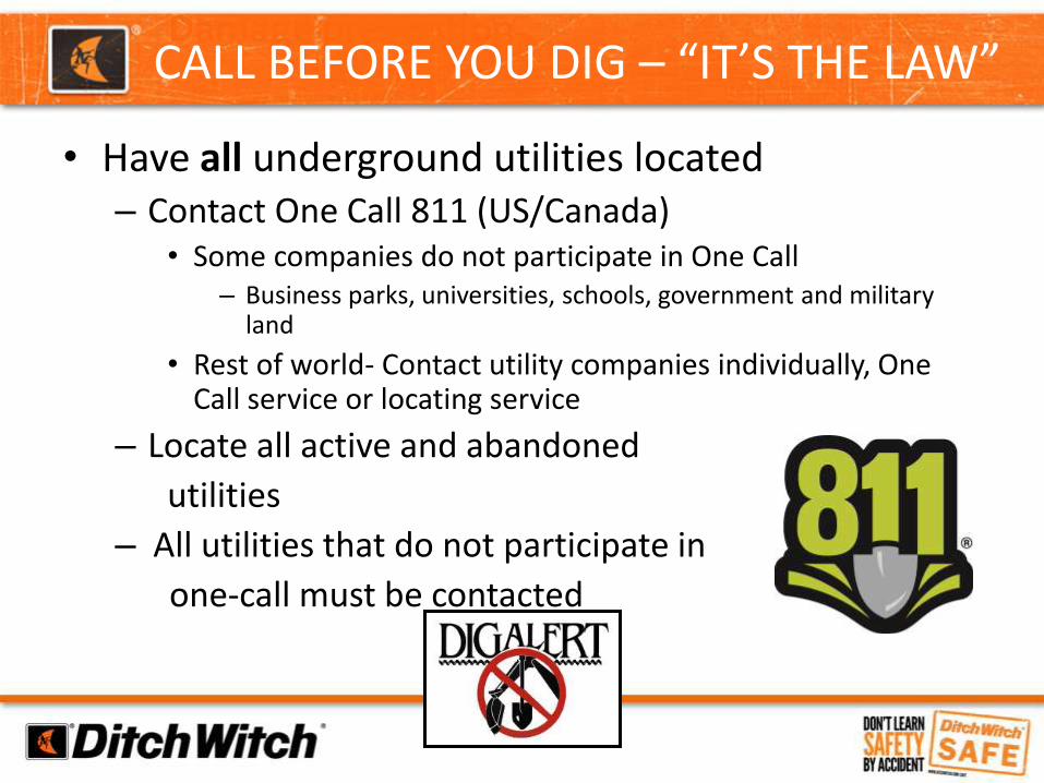
• Have all underground utilities located– Contact One Call 811 (US/Canada)
• Some companies do not participate in One Call– Business parks, universities, schools, government and military
land
• Rest of world- Contact utility companies individually, One Call service or locating service
– Locate all active and abandoned
utilities
– All utilities that do not participate in
one-call must be contacted
CALL BEFORE YOU DIG – “IT’S THE LAW”
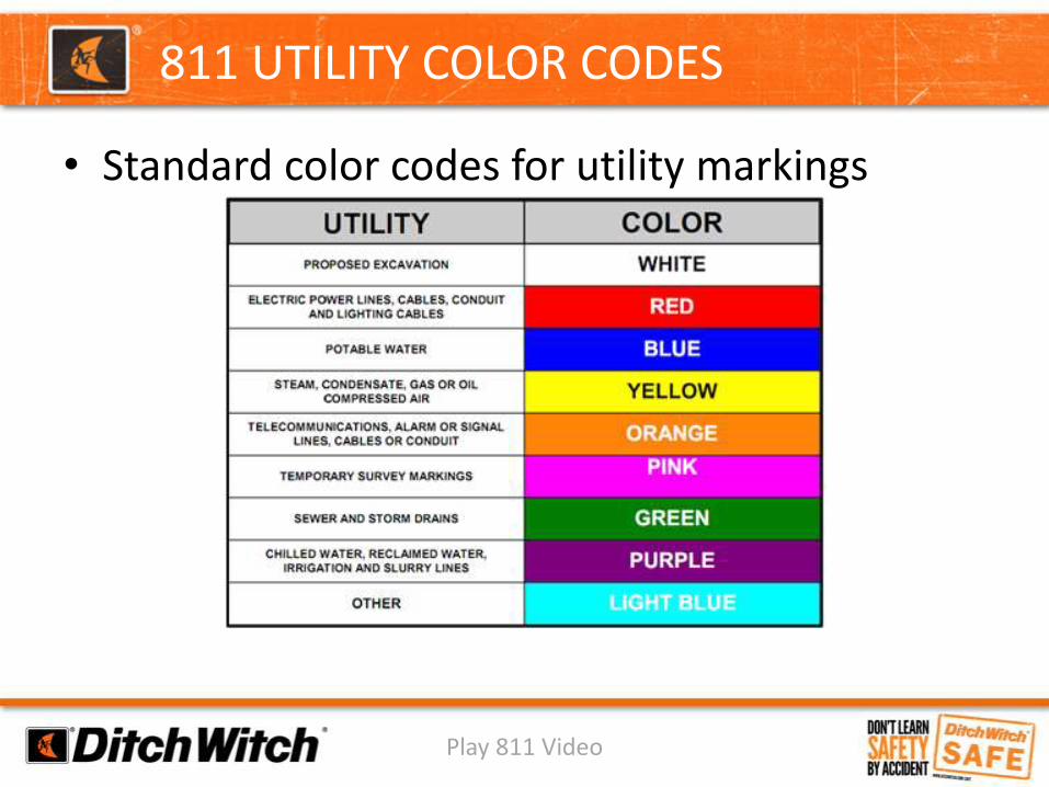
• Standard color codes for utility markings
Play 811 Video
811 UTILITY COLOR CODES

• Use Ditch Witch Electronics to Sweep for Live Power BEFORE you Bore.
SWEEPING FOR POWER EVERY BORE

Verify all locatesFact: CGA reported that approximately 74% of known
damage events in 2012 had a locate ticket called in.
UTILITY DAMAGE STATS

• Potholing– “Daylight” the utilities– Vacuum excavate or
hand dig only within 24” of utilities
– Always dig 12”-18” below utilities
– Inspect for any evidence of any underground hazards• Manholes, meters, vaults,
light/power poles, sunken ground, etc.
CROSS-BORE AVOIDANCE
PROPER TRAINING REQUIRED
Is it necessary to locate sewer lines on the jobsite prior to drilling?
QUESTION
Yes.
It is highly recommended to locate sewer lines. The most popular method is utilizing a sewer beacon
and tracker to find the running line and depth
Additionally, plan to have a camera inspection of all sewer lines in the area after boring is complete.
ANSWER

• Sewer Locating
CROSS-BORE AVOIDANCE

• Review bore plans
– Make pre-bore profile
– Mark proposed borepath
– Sweep for power
– Soil testing for mud mixture
CLASSIFY THE JOBSITE
EVERYONE ON SAME PAGE

Directly Out Of Ops Manual
EMERGENCY PROCEDURESELECTRIC STRIKE
Show DD20 VIDEO
PREPARE CREW

EMERGENCY PROCEDURES – ELECTRIC STRIKE

EMERGENCY PROCEDURES – ELECTRIC STRIKE
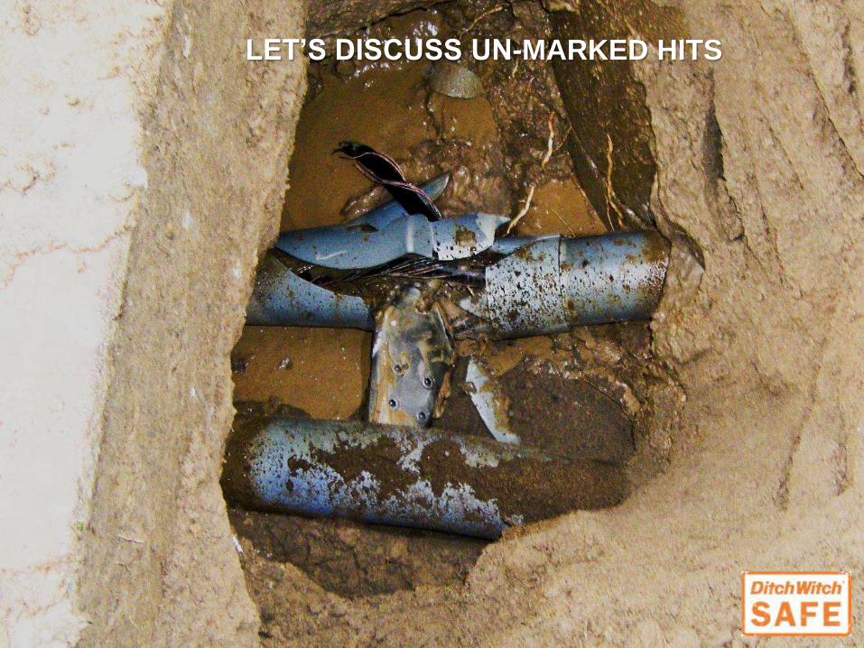
LET’S DISCUSS UN-MARKED HITS

LOCAL UTILITY WAS ON SCENE IN MINUTES

THOUGH IT WAS UN-MARKED, STILL NEED TO
USE COMMON SENSE…

Directly Out Of Ops Manual
EMERGENCY PROCEDURESGAS STRIKE

Gas line located in front of drill at 5’ deep
Crew decided to drill at 3-1/2’ without exposing gas line to verify depth
Hit gas line on 2nd rod in ground
GAS HIT

Gas line not located
Hit gas line on 3rd rod in ground
GAS HIT

Verify all locates• Must visually inspect and measure all crossing
utilities• Locator must be contacted if there are any
questions about the marks. Assumptions must not be made.
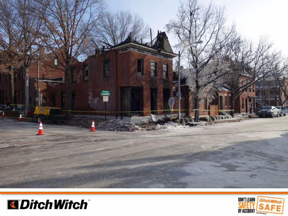
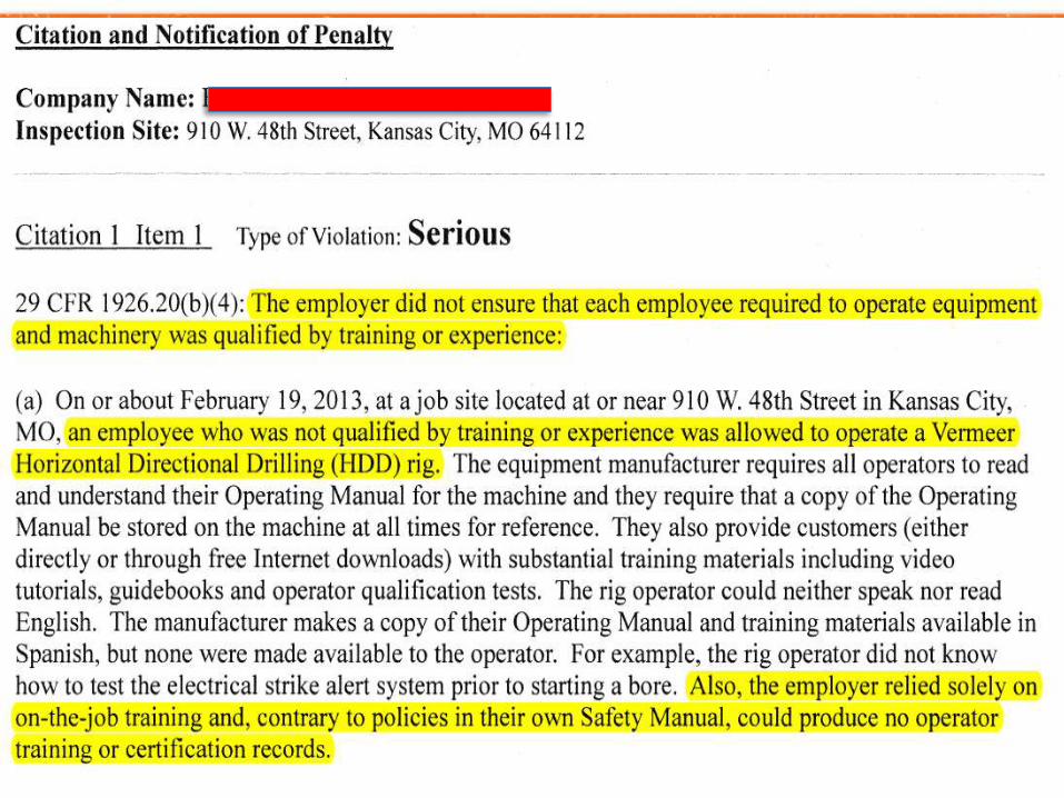
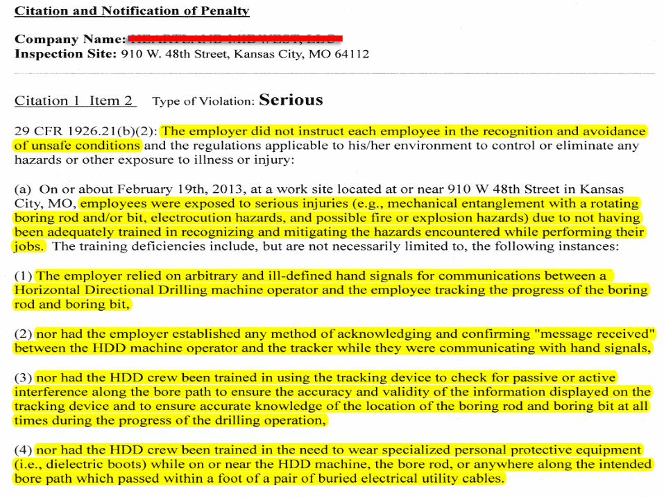
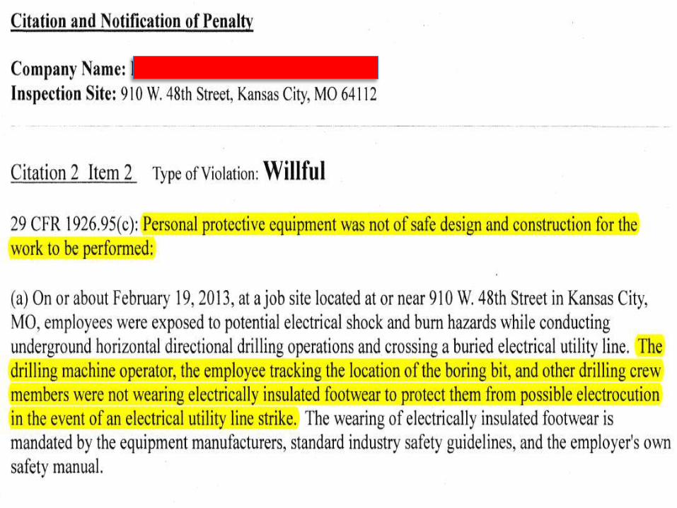
• Example case:– Kansas City, MO– 2013– 1 killed, many injured, drill operator severely injured– Business destroyed and many buildings damaged
DAMAGE PREVENTION

Entry pit Area of strike
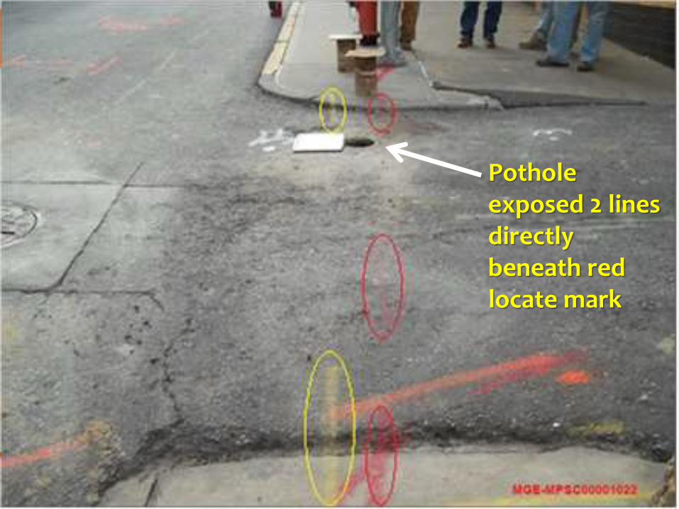
Pothole exposed 2 lines directly beneath red locate mark

After accident it was discovered there were 2 electric lines marked as one.


ELECTRICAL STRIKE SYSTEM

DIELECTRIC BOOTS AND GLOVES
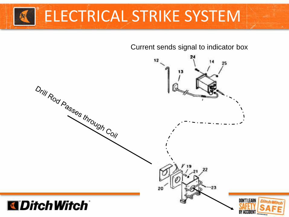
ELECTRICAL STRIKE SYSTEM
Current sends signal to indicator box

ESID
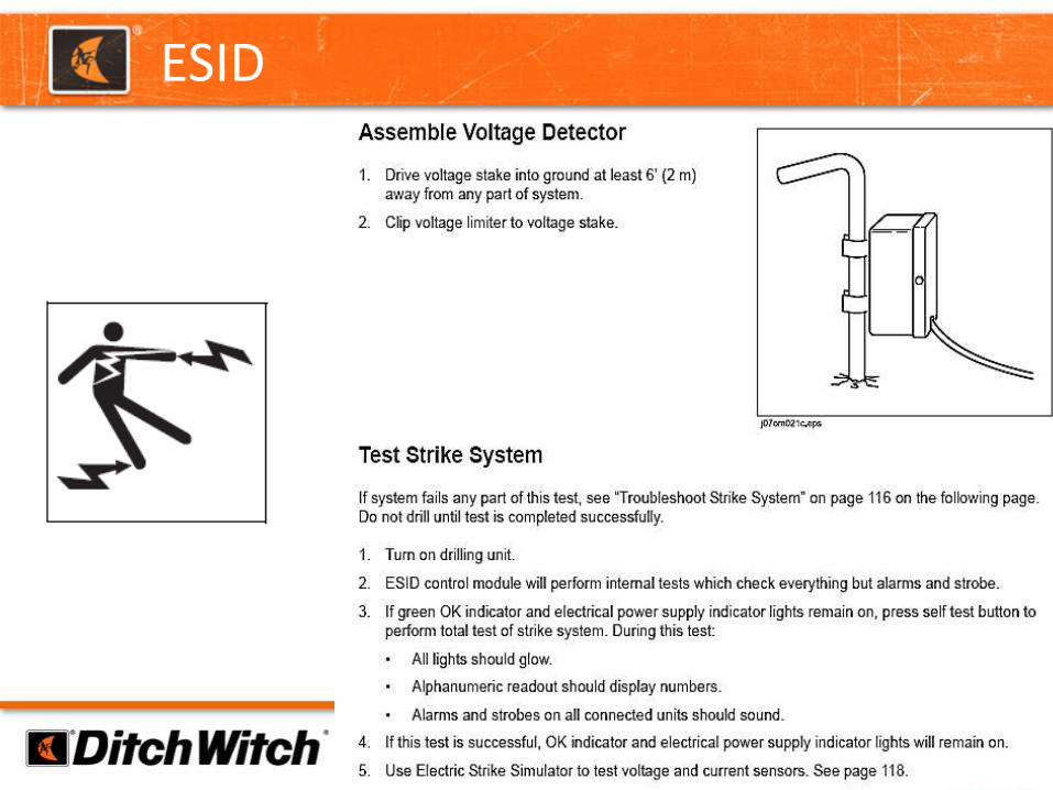
ESID

ESID
TO PROPERLY GROUND THE MACHINE, MAKE SURE AT LEAST ONE ANCHOR IS AT FULL DEPTH, IF NOT BOTH. IF MACHINE IS NOT GROUNDED ITS VERY DANGEROUSE AND OPERATOR IS NOT PROTECTED

WHAT HAPPENS WITH IMPROPER STAKING

DANGERS OF EXPOSED DRILL ROD

DANGERS OF EXPOSED DRILL ROD
Minimum Drill Rod Exposed Always!
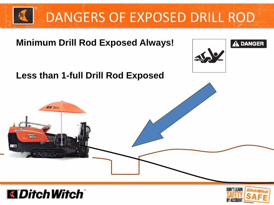
DANGERS OF EXPOSED DRILL ROD
Minimum Drill Rod Exposed Always!
Less than 1-full Drill Rod Exposed

DANGERS OF EXPOSED DRILL ROD
Minimum Drill Rod Exposed Always!
Your creating dangerous and unsafe situation and
your eventually bend the drill pipe and lose torque
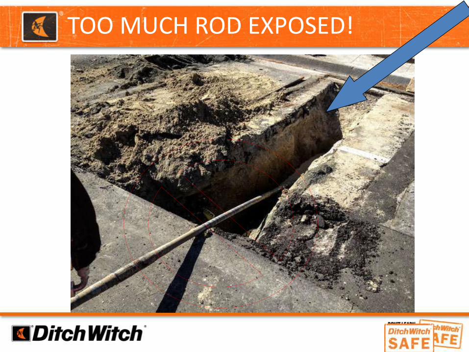
TOO MUCH ROD EXPOSED!

BEND RADIUS & SET BACK

WHAT IS BEND RADIUS?
Bend radius is the max bend you can bend your pipe before it permanently damages the pipe
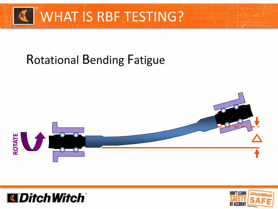
WHAT IS RBF TESTING?
Rotational Bending Fatigue
RO
TATE

RIG ALIGNMENT
Rig Alignment Should be Checked and Adjusted.

TOOL JOINTS
Inner Rotary Shoulder
Outer Rotary Shoulder

Shoulder separates when pipe is bent
Pin carries the bending load
Fretting from movement in the joint
INADEQUATE TORQUE

THIS IS WHAT HAPPENS

CHECK SAVER SUBS DAILY
Check for thread wear and rotary shoulder damage. If it gets damaged, you need to replace it.

LIFE-REDUCING DAMAGE
SCORING IS LIKE
SCORING GLASS

LIFE-REDUCING DAMAGE - SCORING
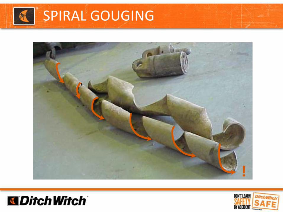
SPIRAL GOUGING
!

OVER-TIGHTENING
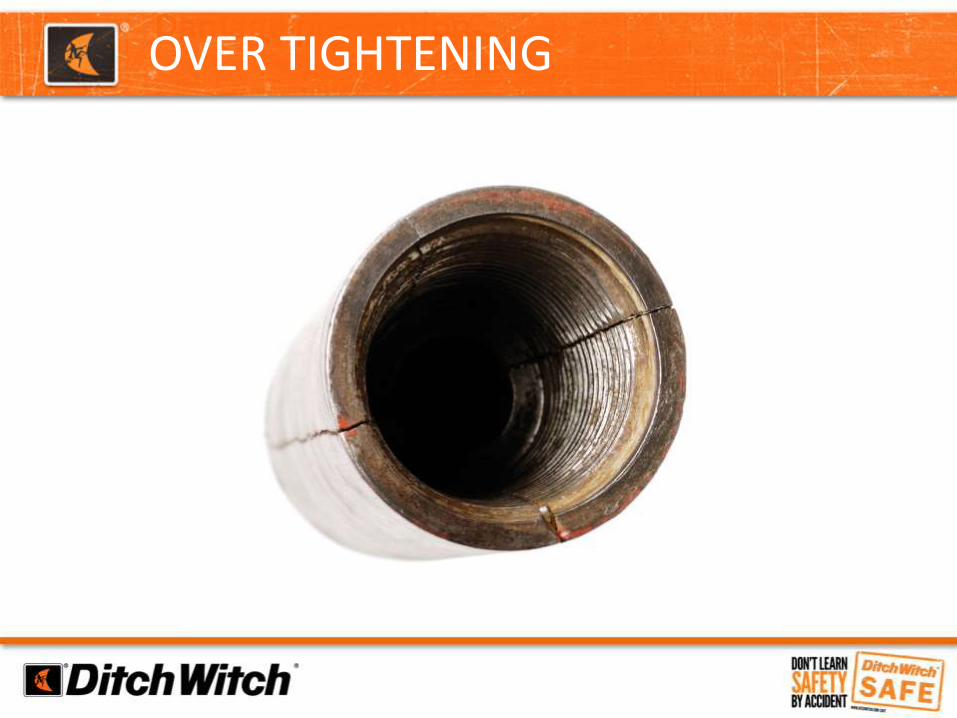
OVER TIGHTENING

EXCEEDING BEND RADIUS

BEND RADIUS
DRILL
MODEL
BEND
RADIUS
JT5 70’
JT922 105’
JT1220 105’
JT20 130’
JT25/30 155’

EXCEEDING BEND RADIUSDitch Witch Drill Rod is tested to
bend at a maximum percent pitch.
Ditch Witch
Drill Model
Maximum Pitch
Change Per
Rod
Drill Rod
Length
JT5 7% 5’
JT922 7% 6’
JT1220 9% 10’
JT20 8% 10’
JT25/30 8% 10’

EXCEEDING BEND RADIUS

SETBACK – EVERY ROD WILL “FEEL IT”

MINIMUM DEPTH – RUNNING LINE

MINIMUM DEPTH – CHEAT SHEET
Show Drill Pipe Maintenance Video
Entry @ -24% 10’ pipe, 8% rod, requires 40’ to level off

DANGERS OF OPEN PITS & DHT

OPEN PIT DANGER
Never enter “any” pit with live drill string
(machine must be shut off!)
Keep all rigging to a minimum
Use proper slings, duct pullers, shackles and swivels.

INSPECT RIGGING FOR WEAR


Show Quick Wrench & EZ Connect EZ Video
Backreaming Tips• Plan backreaming job before drilling. Plan bore path as straight as possible. Check bend limits ofpullback material. Check that appropriate pullback devices are on hand.• Keep all bends as gradual as possible.• Drilling fluid quality is a key factor in backreaming success. Contact your Ditch Witch® dealer forinformation on testing water, selecting additives, and mixing drilling fluid.• Backreaming requires more fluid than drilling. Make sure enough fluid is used.

Swivels are directionaland require inspection & maintenance
Watch Digging Dangers XX Video

QUICK WRENCHES & EZ CONNECT

NEVER, EVER, USE PIPE WRENCHES
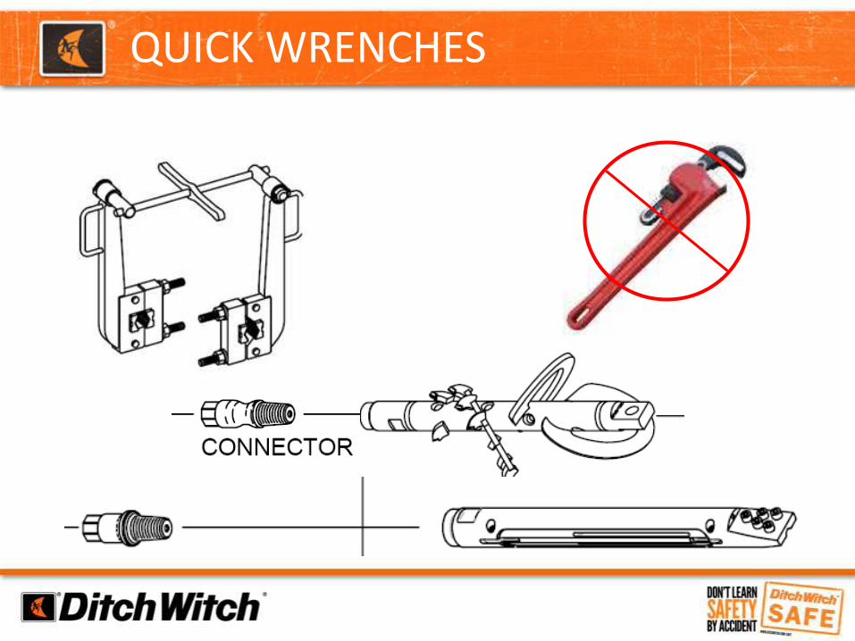
QUICK WRENCHES


QUICK WRENCHE TORQUE UP


TOWING & HAULING

Transport – D.O.T.
Tire Air Pressure
Lug Nuts Torque
Chains & Binder Inspection
Safety Chains and hooks
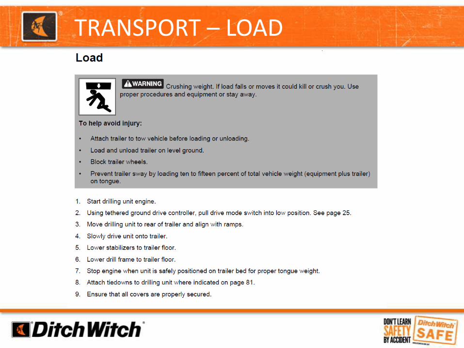
TRANSPORT – LOAD

Transport – tie down

COMMUNICATIONS

COMMUNICATION
• Clear
• Consistent
• Simple
• Quality

HDD SAFETY RE-CAP
Electrical Strike
Emergency Procedures
Exposed Drill Rod
Open Pit Danger
Transporting
Communication

DITCH WITCH ELECTRONICS

ELECTRONIC GUIDANCE

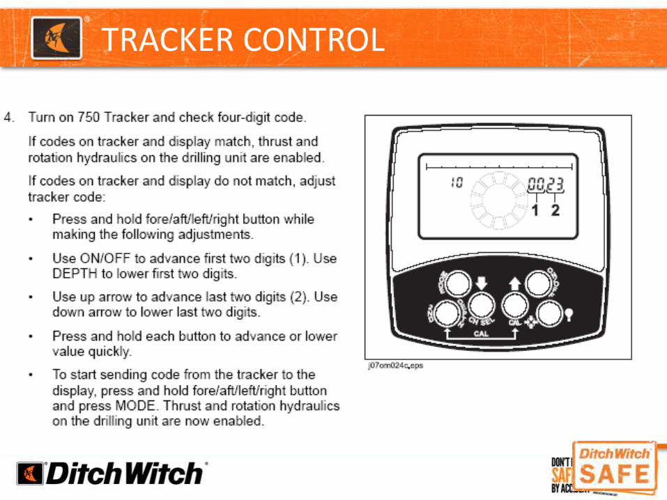
TRACKER CONTROL
TRACKER CONTROL

Tracker control
• Make sure tracker control key on drill is in the proper position to allow the tracker to disable thrust and rotation
• Shut off tracker unit while breaking joints to activate tracker control
TRACKER CONTROL

Tracker control (con’t)
• The green tracker control light on the drill will come on within 16 seconds of shutting off the tracker to indicate that the operator controls are disabled.
Exit PitTRACKER CONTROL

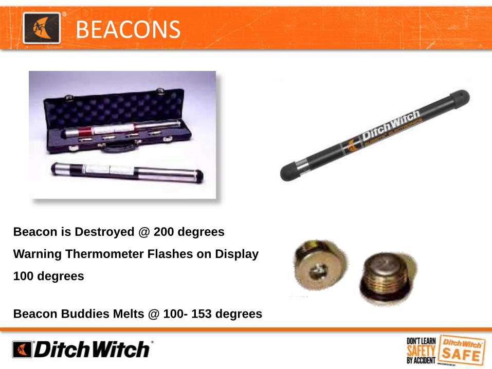
BEACONS
Beacon is Destroyed @ 200 degrees
Warning Thermometer Flashes on Display
100 degrees
Beacon Buddies Melts @ 100- 153 degrees

752 TRACKER
Sweep for Power?


PIPE & CABLE LOCATING
• Transmitter Optional Available
• Used in Conjunction with 752 Tracker
• Accuracy
• Verify Locates, Time Efficient

• Use Ditch Witch Electronics to Sweep for Live Power BEFORE you Bore.
SWEEPING FOR POWER EVERY BORE

WHY WE SWEEP FOR POWER
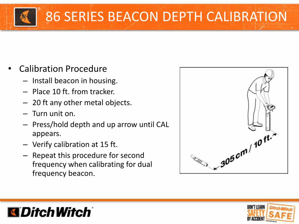
86 SERIES BEACON DEPTH CALIBRATION
• Calibration Procedure– Install beacon in housing.
– Place 10 ft. from tracker.
– 20 ft any other metal objects.
– Turn unit on.
– Press/hold depth and up arrow until CAL appears.
– Verify calibration at 15 ft.
– Repeat this procedure for second frequency when calibrating for dual frequency beacon.

86 Series Beacon Depth Calibration
• Calibration Tips– Beacon and tracker should not be
moved/rotated until calibration is complete.
– Large metal objects, rebar, power lines and other kinds of interference will affect calibration.
– Calibrate at the jobsite.
– Only depth estimation is affected by this calibration.

Interference can come in two forms either
• Active
• Passive
These types of interference can cause
- Loss of beacon information
- Erratic beacon signal
- Inaccurate depth estimates
- Difficulty in locating
INTERFERENCE CAN COME IN TWO FORMS:
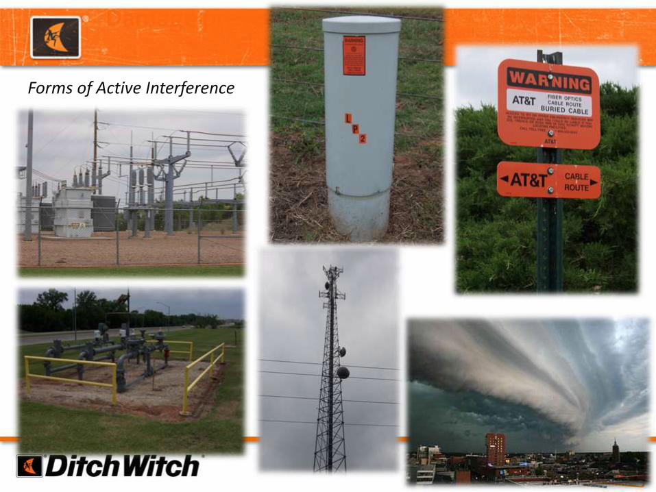
Forms of Active InterferenceForms of Active Interference
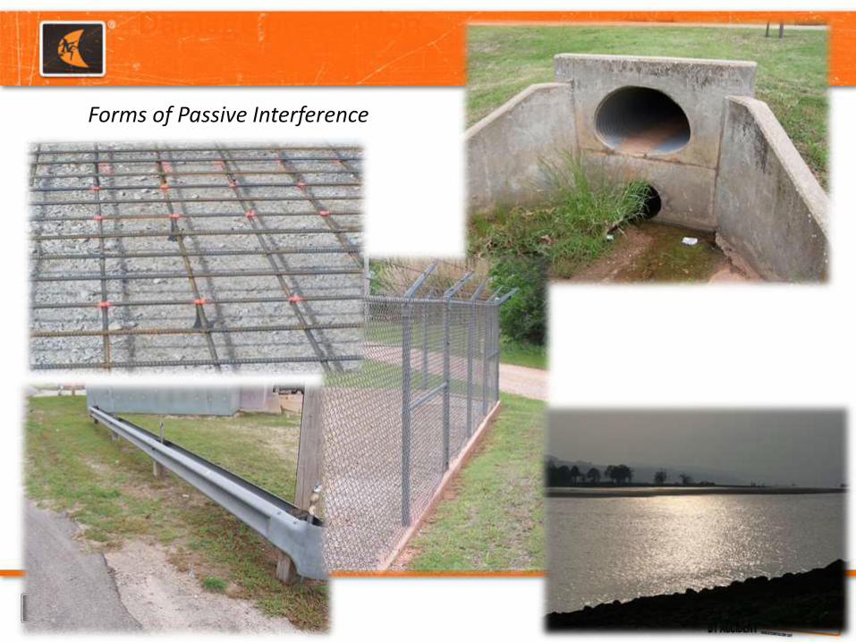
Forms of Passive InterferenceForms of Passive Interference

Checking for interference and noise with your tracking system.
CHECKING FOR INTERFERENCE AND NOISE WITH YOUR TRACKING SYSTEM.

WHAT CAN BE DONE ABOUT SHALLOW NOISE FLOORS?
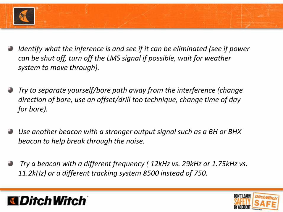
Identify what the inference is and see if it can be eliminated (see if power can be shut off, turn off the LMS signal if possible, wait for weather system to move through).
Try to separate yourself/bore path away from the interference (change direction of bore, use an offset/drill too technique, change time of day for bore).
Use another beacon with a stronger output signal such as a BH or BHX beacon to help break through the noise.
Try a beacon with a different frequency ( 12kHz vs. 29kHz or 1.75kHz vs. 11.2kHz) or a different tracking system 8500 instead of 750.


TROUBLESHOOTING 752 TRACKING SYSTEM
• Tracker not communicating with remote display.– Ensure radios in both units are on same channel.
– Make sure radio is turned on.– Radio Test Mode
• Tracker and Display must be on the same channel. • With Tracker off, press and hold fore/aft/left/right arrow button while
turning the tracker on. Release F/A/L/R when test appears on screen. • Check Remote Display for information changes on screen. • Process of elimination
– Perform visual inspection of keypad and overlay.

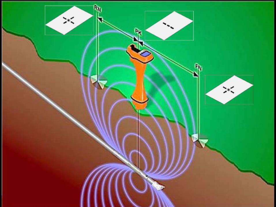
GHOST SIGNALS
Both Arrows Must Show
Ghost Signals

LOADING THE BEACON IN A HOUSING
BATTERY TROUBLESHOOTING
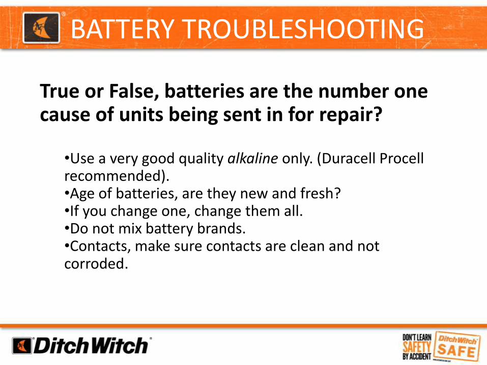
True or False, batteries are the number one cause of units being sent in for repair?
•Use a very good quality alkaline only. (Duracell Procellrecommended). •Age of batteries, are they new and fresh?•If you change one, change them all.•Do not mix battery brands.•Contacts, make sure contacts are clean and not corroded.
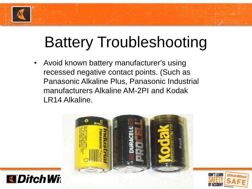
Battery Troubleshooting
• Avoid known battery manufacturer's using
recessed negative contact points. (Such as
Panasonic Alkaline Plus, Panasonic Industrial
manufacturers Alkaline AM-2PI and Kodak
LR14 Alkaline.

TRACKER BATTERY INFORMATION
• C-cell alkaline batteries•4-8 hrs. life
• Rechargeable option•Accupower 6000 mAh NiMH C-cell
•Up to 10 hrs life in cold temperatures•HiTech IC-U6S1234 LCD or LED smart charger
•Approximately 6 hrs to charge 6 batteries.
•Supplier: www.onlybatteries.com
•Spring WEAR


DITCH WITCH ELECTRONICS
Tracker Control
Communication
Calibration and Confirmation
Interference
Remote Guidance
Sweeping For Power
Trouble Shooting
Batteries
Pipe and Cable Locating

Questions?
VACUUM EXCAVATION
Day 2

Vacuum Training Course

Why We’re Here
•Vacuum Trailers provide operators with:• Ability to keep jobsites free of
debris that can be a safety hazard.
• Ability to “daylight” utilities more effectively and safer than mechanical excavation
• Efficient means to clear work areas to perform tasks.
• Environmentally safe means to store, transport, and dump all debris in designated locations.
Watch Vac Safety Video

Potential Hazards• Struck by• Crushing• Fire• Electrocution• Suffocation

Precautions• When driving, consider effects of sloshing water or
spoils in tanks. Make sure tow vehicle is appropriately sized.
• Wear appropriate personal protective equipment as needed. Consider hard hat, safety glasses, gloves, boots, metatarsal guards, and hearing protection.
• When cleaning filter, use respirator if necessary depending on material excavated.

Dielectric Boots and Gloves• Wear appropriately rated electrically insulated boots
with pant legs tucked in, and appropriately rated electrically insulated gloves when operating on an electrical jobsite. If using water, dielectric boots should be worn.

Precautions• Keep pressure wand away from body parts.• Do not put the end of the suction hose or tools on
any body part.• Do not open spoils tank door or filter doors until
tank has been de-pressurized (reverse flow) and fluids and any flow-able spoils have been emptied.
• Reverse flow should not be engaged unless tank drain valves are open first.

Precautions• No one should be under raised components, such as
the tank door or the raised tank, without using lockout devices.
• Drain fluids and flowable spoils before raising the tank.
• Stay away from door when dumping.• Ensure you have a clear view of the door area and
beneath the tank when closing door or lowering tank.
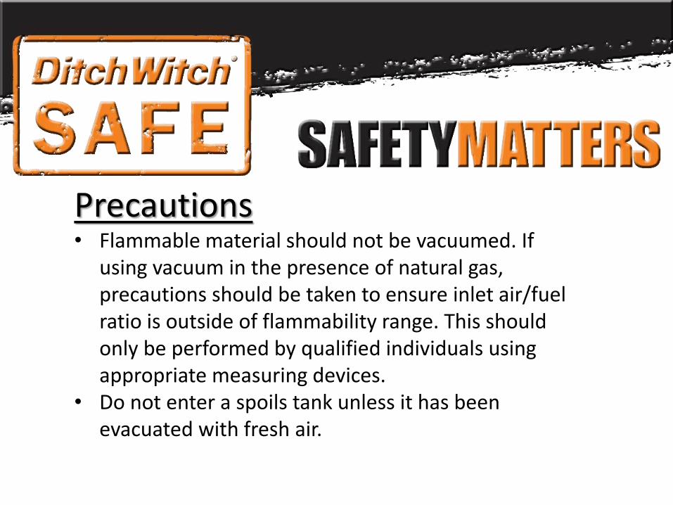
Precautions• Flammable material should not be vacuumed. If
using vacuum in the presence of natural gas, precautions should be taken to ensure inlet air/fuel ratio is outside of flammability range. This should only be performed by qualified individuals using appropriate measuring devices.
• Do not enter a spoils tank unless it has been evacuated with fresh air.
Information/Facts• High pressure water can cut through skin, wood, and
metal.• Utility age and physical composition can affect
vulnerability to damage by wand.• Suction can quickly suffocate and can pull blood
through the skin.• High pressure water can cut through clothing and
skin.
Information/Facts• Static charge can build in the vacuum hose. This can
generate a spark and depending on the conditions and material being excavated may ignite.
• Hazardous materials require special transport vehicles. Most vacuum excavators are not equipped to transport hazardous materials.
• High pressure water can cause excavated material and rocks to be thrown.

Best Practices

Trailer InspectionVacuum equipment checks are vital to equipment function. Some examples are:
• Checking the fluid levels.
• Checking equipment for wear and tear.
• Trailer hitch inspection.

Job Planning• Identify and communicate any hazards• Have a valid locate on site before starting the
excavation• Classify jobsite (soil, traffic, locate marks, possible
un-marked utilities, etc.)• Work interruption (action plan incase of damaged
underground utilities)• If trying to locate a damaged utility, that line should
be de-energized and isolated prior to excavation.• Appropriate warning signs and/or barriers

Trailer Setup
Positioning the equipment correctly has several steps: – Proper trailer positioning.
– Proper equipment stabilization.
– Chock trailer wheels.
– Maintain proper boom clearance for overhead lines

Personal Protective Equipment• The wand should never remain motionless.• Do not aim directly at utilities.• Maintain as much distance as possible between the
end of the wand and the utility. At least 8” is recommended, depending on the nozzle used.
• Never use more pressure than what is necessary to break up the soil.

When Exposing Utilities• The minimum requirement for safety equipment to
be used by workers should be:• Approved head protection• Approved foot protection• Approved eye protection• Approved hearing protection• Approved clothing (flame-resistant if needed)• Suitable hand protection

Turbo/Rotary Nozzle• The use of a Turbo or Rotary Nozzle
should always be used to minimize any possible damage to utilities and increase excavation production• Maximum water pressure using a rotating
nozzle:All depths -- 3000 psi
• Maximum water pressure using a straight tip:
0-18” deep -- 2500 psiOver 18” deep – 1500 psi


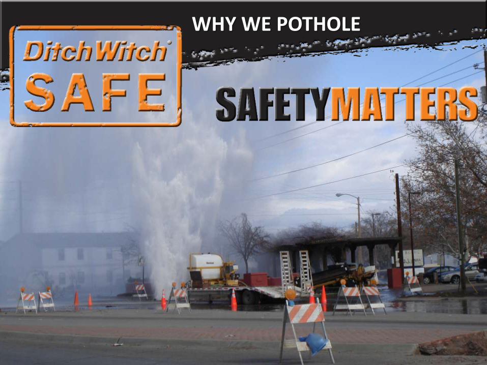
WHY WE POTHOLEWHY WE POTHOLE

WHY WE POTHOLEWHY WE POTHOLE

REQUIRED MAINTENANCE
Day 2

MACHINE WALK AROUND
Complete Machine Maintenance
Review all Maintenance Intervals
Review and Wearables
Track Adjustments
Mud Mixer Maintenance
FIELD OPERATION
THANK YOU!
HORIZONTAL DIRECTIONAL DRILLING
TRAINING COURSE