hazardous waste incinerator - maharashtra pollution ...mpcb.gov.in/images/hwincinerator.pdf ·...
TRANSCRIPT
Hazardous Waste Management Series HAZWAMS/30/2005-06
GUIDELINES FOR
COMMON HAZARDOUS WASTE INCINERATION
Central Pollution Control Board Ministry of Environment & Forests
e.mail: [email protected] Website: www.cpcb.nic.in
June, 2005
2
Dr. V. Rajagopalan Chairman
Foreword Hazardous wastes generated by the industries are required to be managed as per the Hazardous Waste (Management & Handling) Rules, 1989, as amended. About 4.4% of hazardous waste generated in the country is of the nature, which has to be incinerated. Besides, segregated organic residues, highly concentrated effluents such as mother liquors and toxic effluents not feasible for physico-chemical, biological treatment also require proper disposal through incineration. Hierarchy of options in hazardous waste management, in sequence, is to switchover to cleaner technologies, cleaner production options and exploring the potential for re-using, recycling, recovering, renovation before sending to incineration and secured land filling. Common incineration facilities are now in operation in the country. Incineration of hazardous waste from many industries is a task that requires comprehensive knowledge & skill in respect of chemistry, thermal engineering and environmental engineering. Therefore, the Central Pollution Control Board studied the common incineration facilities and formulated guidelines for proper design, operation and to meet the standards. While framing the guidelines, CPCB considered the preliminary draft prepared by the Committee constituted by the Chairman, CPCB, technology & operation of Indigenous incineration facilities and experiences of European incineration facilities. I take this opportunity to register the sincere efforts made by Er. N.K. Verma and Er. N. Sateesh Babu in bringing out the guidelines with the association of GTZ-ASEM experts, in particular, Prof. Thomas Kolb, Karlsruhe University, Germany. I understand this publication will be highly useful for the existing common incineration facilities, for those planning to set-up new facilities, regulatory officers and all others concerned to the pollution control and hazardous waste management in the country.
(V. Rajagopalan)

3
TEAM
Project Team : Sh. N.K. Verma, Additional Director, CPCB Sh. N. Sateesh Babu, Env. Engineer, CPCB Dr. Peter Henschel, Senior Adviser, GTZ-ASEM
Report Preparation
: Sh. N. Sateesh Babu, Env. Engineer
Technical Editing
: Prof. Thomas Kolb, Thermal Waste Treatment Division, Karlsruhe University, Germany Sh. N.K. Verma, Additional Director
Report Finalization
: Dr. V. Rajagopalan, Chairman, CPCB Dr. B. Sengupta, Member Secretary, CPCB
4
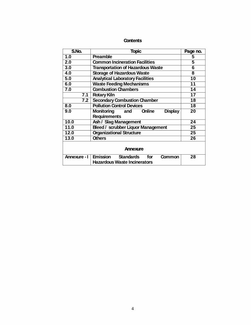
Contents
S.No. Topic Page no. 1.0 Preamble 5 2.0 Common Incineration Facilities 5 3.0 Transportation of Hazardous Waste 6 4.0 Storage of Hazardous Waste 8 5.0 Analytical Laboratory Facilities 10 6.0 Waste Feeding Mechanisms 11 7.0 Combustion Chambers 14
7.1 Rotary Kiln 17 7.2 Secondary Combustion Chamber 18
8.0 Pollution Control Devices 18 9.0 Monitoring and Online Display
Requirements 20
10.0 Ash / Slag Management 24 11.0 Bleed / scrubber Liquor Management 25 12.0 Organizational Structure 25 13.0 Others 26
Annexure
Annexure - I Emission Standards for Common Hazardous Waste Incinerators
28

5
1.0 PREAMBLE
Thermal oxidation through incinerator is one of the proven technologies for destruction of hazardous waste in all the forms i.e. solid / semi solid / liquid and gaseous, based on the feeding system, so as to render them innocuous in the form of non-toxic and non-hazardous residues. Though it is a solution for destruction of complex hazardous waste, requires knowledge to judge the compatibility of various wastes for the purpose of homogenization of feeding waste, to operate and maintain thermal processes, pollution control devices, which demands skill & experience, in order to comply with the environmental regulations for common hazardous waste incineration facilities (ANNEXURE - I). The Common incineration facilities are, in principle, expected to handle the hazardous waste in solid and liquid forms having high degree of variation in respect of characteristics due to different nature of member industries, which will have direct bearing on efficiency of combustion system and pollution control devices. Therefore, experience in other parts of the world, particularly in case of handling hazardous waste in solid form, drive us to adopt rotary kilns followed by secondary combustion chambers as a set-up for combustion part of the incineration system, unless other combinations demonstrate equally in delivering required efficiency. As such, in India, existing three common incineration facilities do have the same combination; therefore the guidelines presented in this document cover such set-up.
2.0 COMMON INCINERATION FACILITIES
Common hazardous waste incineration facilities are those facilities, which handle hazardous waste from more than one industry either installed as an integral part or located elsewhere. Various concerned components of common incineration facility include proper transportation, storage, analytical laboratory facilities, feeding mechanism, incineration system (rotary kiln & post combustion chamber), gas cleaning system, tail gas monitoring facilities with automatic on-line monitoring & control facilities, ash/slag management, bleed/scrubber liquor management and measures for health protection of workers. Guidelines for maintaining each of these components in order to comply with the prescribed standards are given in the subsequent chapters.
3.0 TRANSPORTATION OF HAZARDOUS WASTE
All the provisions corresponding to transportation of hazardous wastes under various Acts including the Hazardous Wastes (Management & Handling) Rules & subsequent amendments and Motor Vehicle Act, shall be duly complied with, in all respects (coding, containers, manifest system etc.). Guidelines for transportation of hazardous waste include, but not limited, to the following:

6
Generators responsibilities: a. Generator of the hazardous waste shall ensure that wastes are
packaged in a manner suitable for safe handling, storage and transportation. Labeling on packaging is readily visible and material used for packaging shall withstand physical and climatic conditions.
b. Generator shall ensure that information regarding characteristics of
wastes particularly in terms of being Corrosive, Reactive, Ignitable or Toxic is provided on the label.
c. All hazardous waste containers shall be provided with a general label
as given in Form 8 in Hazardous Waste (Management & Handling) Rules, 1989, as amended.
d. Transporter shall not accept hazardous wastes from an occupier
(generator) unless six-copy (with colour codes) of the manifest (Form 9) is provided by the generator. The transporter shall give a copy of the manifest signed and dated to the generator and retain the remaining four copies to be used for further necessary action prescribed in the Hazardous Wastes (Management & Handling) Rules, 1989, as under:
Copy 1 (White) Forwarded to the Pollution Control Board
by the occupier Copy 2 (Light
Yellow) Signed by the transporter and retained by the occupier
Copy 3 (Pink) Retained by the operator of a facility Copy 4 (Orange) Returned to the transporter by the
operator of facility after accepting waste Copy 5 (Green) Forward to Pollution Control Board by the
operator of facility after disposal. Copy 6 (Blue) Returned to the occupier by the operator
of the facility after disposal.
e. Generator shall provide the transporter with relevant information in Form 10 i.e. Transport Emergency (TREM) Card regarding the hazardous nature of the waste and measures to be taken in case of an emergency.
Transporters responsibilities:
a. Obtaining permission from SPCB for transport of hazardous waste [in addition to any other permissions that may be required under the Motor Vehicles (Amendment) Act of 1988].
b. The transport vehicles shall be designed suitably to handle and transport the hazardous wastes of various characteristics.
c. Maintaining the manifest system as required.
d. Transporting the wastes in closed containers at all times

7
e. Delivering the wastes at designated points
f. Informing SPCB and other regulatory authorities immediately in case of spillage, leakage or other accidents during transportation
g. Cleanup in case of contamination.
4.0 STORAGE OF HAZARDOUS WASTE
a. Separate area should be earmarked for storing the waste and storage area may consist of different cells for storing different kinds of hazardous wastes.
b. Ignitable, reactive and non-compatible wastes shall be stored
separately. c. Adequate storage capacity shall be provided in the premises d. No open storage is permissible and the designated hazardous waste
storage area shall have proper enclosures, including safety requirements.
e. In order to have appropriate measures to prevent percolation of spills,
leaks etc. to the soil and ground water, the storage area may be provided with concrete pavement and / or welded iron sheet depending on the characteristics of the waste handled.
f. Storage area shall be designed in such a way that the floor level is at
least 150 mm above the maximum flood level. g. Proper stacking of drums with wooden frames shall be practised. h. Incase of spills / leaks, cotton shall be used for cleaning instead of
water. i. Signboards showing precautionary measures to be taken, in case of
normal and emergency situations shall be displayed at appropriate locations.
j. To the extent possible, manual operations with in storage area are to
be avoided. Incase of personnel use, proper precautions need to be taken, particularly during loading / unloading of liquid hazardous. Waste in drums
k. A system for inspection of storage area to check the conditions of the
containers, spillages, leakages etc. shall be established and proper records shall be maintained.

8
5.0 ANALYTICAL LABORATORY FACILITIES
a. Generators sending hazardous waste to the incineration facility are required to provide necessary test report of hazardous waste to the operator along with the information on the process(s) of its generation.
b. The tests to be conducted at incineration facility shall be with an
objective to study i) Storage & feeding requirements; ii) operating conditions of the furnaces; iii) Feed concentration within the efficiency levels of air pollution control devices to comply with flue gas standards. The activity specific relevant parameters are indicated below:
Storage & feeding requirements: Physical form of waste, pH,
hazardous waste properties such as inflammability, reactivity, compatibility with other wastes etc. for segregating the waste and to store accordingly, in order to suit feeding mechanism.
Operating conditions of the furnaces: viscosity, moisture content,
total organic carbon, calorific value, volatility of the waste, special incompatible wastes, inorganic salts, metals etc.
Air pollution control devices: chlorides & other halogens, sulphur,
nitrates, mercury & other heavy metals etc. Therefore, relevant parameters may be analyzed while accepting the
waste. c. The laboratory facilities shall give clear directions to the operators,
two days in advance as far as possible, regarding type of waste to be incinerated in a particular date and its properties.
d. Therefore, the laboratory at the incineration facilities shall be capable
of monitoring all the above parameters. 6.0 WASTE FEEDING MECHANISMS
a. Maintaining designed heat capacity of the combustion chambers under varying feed calorific values demands skill. In absence of proper hands on training and adequate knowledge, the minimum negative pressure could not be maintained at all the times leading to diffused emissions / sudden puffing of emissions into the secondary combustion chambers constraining the retention time resulting in poor efficiency. Besides, these temperature fluctuations will have negative bearing on refractory and insulation material.
b. Therefore, continuous feeding of homogeneous waste having same /
similar calorific value to the combustion chambers is the desired choice. However, often maintaining homogeneous feed of waste is not feasible due to incompatibility of different wastes for mixing.

9
Conventionally, hazardous wastes in solid form are fed through a hydraulic system, which will have automatic two gates i.e. once the outside plate is closed, inner side plate is opened and solid waste mass is hydraulically pushed inside the Kiln and once the inner side plate is closed, outer plate is opened for next batch of solid waste. This system, besides negative pressure in the combustion chambers is required to ensure safety and to prevent workmen exposure to thermal radiation.
c. Thus, waste-feeding mechanism plays an important role to achieve
desired combustion efficiencies. For example, the variety of wastes received from the member industries can be classified into following for better control of combustion:
Waste in solid form
Property Options
High calorific value containing waste (organic residues)
Quantity of solid mass feeding may be reduced in each charging to contain temperature shoot-ups. Besides, following are used in specific cases: Low calorific value liquid waste may be parallelly injected; and/or Steam may be parallelly injected
Reactive waste, which can not be mixed with others
Sealed drums, as such, may be charged into the kilns. Depending on calorific value, size of the drum / container may be specified to the member industry for such waste.
Other mixable solid waste having moderate calorific value
May be homogenized to the extent possible and charged to the kilns at desired quantity of packets and frequency.
Specific materials which melts on heating
Here, the possibility would be to ask the member industry to store in required capacity of the container, which can be directly injected with out heating; or to provide a system by which such drums can be heated-up and can be charged through closed-loop pressurized nitrogen.

10
Waste in semi solid form
Property Options Very high solids concentration
Fully shelled (to prevent diffused emissions) screw pumps may be a choice
Relatively low conc. of solids / low viscosity
Pumps similar to the one used for cement concrete charging may be used.
Waste in semi solid form
Property Options
Highly reactive / inflammable liquids
May be directly injected into combustion chambers without mixing with other wastes. The charging from the containers may be through closed loop nitrogen pressure purging.
Liquids having high calorific value (ex. contaminated solvents)
Can replace auxiliary fuel requirement, once the combustion chambers reaches to its designed temperatures.
Liquids having properties similar to that of auxiliary fuel
Once it is established, these liquids can be used for raising the initial temperature of the combustion chambers. However, specific tests in support of such claims be produced by a recognized credible third party.
Liquids having low calorific values
These may be injected in to kilns to suppress the temperature shoot-ups due to high calorific solid/ other special liquid waste feeds.
d. Depending on type of wastes received, the scheme shall be established
by the common incineration facility and the member industry shall place the corresponding code number/ sticker and it is to be verified by analytical laboratory of common incineration facility to ensure appropriate feeding by operator of the facility.
e. While charging the liquid hazardous waste, filtering the liquids may be
required to avoid chocking of pumps. f. Non-easily pumpable wastes (ex. High viscous, having high solids
content etc.) may require pressurized nitrogen purging for charging the liquid to the combustion chambers.
g. Incase of emptying liquid waste containing drums by inserting suction
pumps & induced draft (hoods and ducts), set-up above such drum emptying area for collection of volatile organic compounds (VOCs) must be ensured. These collected diffused emissions must be controlled / routed to the combustion chambers.
11
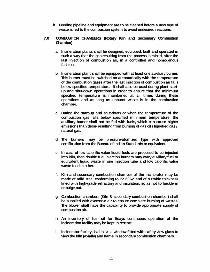
h. Feeding pipeline and equipment are to be cleaned before a new type of waste is fed to the combustion system to avoid undesired reactions.
7.0 COMBUSTION CHAMBERS (Rotary Kiln and Secondary Combustion
Chamber)
a. Incineration plants shall be designed, equipped, built and operated in such a way that the gas resulting from the process is raised, after the last injection of combustion air, in a controlled and homogenous fashion.
b. Incineration plant shall be equipped with at least one auxiliary burner.
This burner must be switched on automatically with the temperature of the combustion gases after the last injection of combustion air falls below specified temperature. It shall also be used during plant start-up and shut-down operations in order to ensure that the minimum specified temperature is maintained at all times during these operations and as long as unburnt waste is in the combustion chamber.
c. During the start-up and shut-down or when the temperature of the
combustion gas falls below specified minimum temperature, the auxiliary burner shall not be fed with fuels, which can cause higher emissions than those resulting from burning of gas oil /liquefied gas / natural gas.
d. The burners may be pressure-atomized type with approved
certification from the Bureau of Indian Standards or equivalent.
e. In case of low calorific value liquid fuels are proposed to be injected into kiln, then double fuel injection burners may carry auxiliary fuel or equivalent liquid waste in one injection tube and low calorific value waste feed in other.
f. Kiln and secondary combustion chamber of the incinerator may be
made of mild steel conforming to IS: 2062 and of suitable thickness lined with high-grade refractory and insulation, so as not to buckle in or bulge out.
g. Combustion chambers (Kiln & secondary combustion chamber) shall
be supplied with excessive air to ensure complete burning of wastes. The blower shall have the capability to provide appropriate supply of combustion air.
h. An inventory of fuel oil for 5days continuous operation of the
incineration facility may be kept in reserve.
i. Incinerator facility shall have a window fitted with safety view glass to view the kiln (axially) and flame in secondary combustion chambers.

12
j. As the common incineration systems will be handling wastes having varying heat value, and while ensuring TOC and LOI requirements in the ash/slag, there are possibilities for sudden rise of temperatures in the kiln. Therefore, the facilities may like to have thermal refractory bricks and insulation capable of withstanding a minimum temperature of 1,300°C (typically, corundum / chromium bricks).
k. Needful safety arrangement must be provided in case of high-pressure
development in the furnace.
l. Interlocking arrangements for CO and temperature controls (in primary and secondary chamber) with feeding devices shall also be provided.
m. All the burners are to be equipped with flame control system (if no
flame is detected, fuel injection has to be stopped, automatically – use of fast-stop-valve).
n. Whenever the pressure in the combustion chambers becomes
positive, immediately the feeding of waste shall be stopped and needful measures be taken to restore negative pressure.
o. Exit doors shall be provided at suitable place, one each on the primary
kiln and the secondary chamber of the incinerator for ease in inspection and maintenance.
7.1 Rotary Kiln
a. To maintain designed heat capacity of the kiln, quantity of the solid
waste injection package (kg/single injection) shall be adjusted w.r.t. calorific value of the waste feed.
b. When a high calorific value possessing solid waste is injected in
packets, the size of each injection may be reduced, such that the peak CO concentration in the Kiln does not exceed too high in the initial stage, creating shooting of emissions to the secondary chamber, thereby crisis in ensuring the required retention time.
c. Appropriate slope (in general, 3 degrees), rotation rates (around
10/hr) and solid waste residence time (1-10 hrs) may be adjusted for the kilns, in order to achieve total organic carbon (TOC) and loss on ignition (LOI) requirements in the ash/slag.
d. To ensure life of refractory and insulation bricks, it is a practice to
feed silica and glass in appropriate ratios to the kilns to form a cover over the refractory lining, as and when the thickness of the layer reduces.
e. It has been reported that reduction of out-side surface temperature of
the rotary kiln enhances the life of refractory bricks and lining. Thus may be explored, where feasible.
13
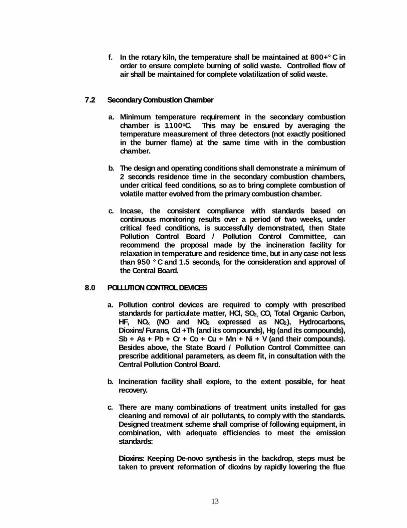
f. In the rotary kiln, the temperature shall be maintained at 800+°C in
order to ensure complete burning of solid waste. Controlled flow of air shall be maintained for complete volatilization of solid waste.
7.2 Secondary Combustion Chamber a. Minimum temperature requirement in the secondary combustion
chamber is 1100oC. This may be ensured by averaging the temperature measurement of three detectors (not exactly positioned in the burner flame) at the same time with in the combustion chamber.
b. The design and operating conditions shall demonstrate a minimum of
2 seconds residence time in the secondary combustion chambers, under critical feed conditions, so as to bring complete combustion of volatile matter evolved from the primary combustion chamber.
c. Incase, the consistent compliance with standards based on
continuous monitoring results over a period of two weeks, under critical feed conditions, is successfully demonstrated, then State Pollution Control Board / Pollution Control Committee, can recommend the proposal made by the incineration facility for relaxation in temperature and residence time, but in any case not less than 950 °C and 1.5 seconds, for the consideration and approval of the Central Board.
8.0 POLLUTION CONTROL DEVICES
a. Pollution control devices are required to comply with prescribed standards for particulate matter, HCl, SO2, CO, Total Organic Carbon, HF, NOx (NO and NO2 expressed as NO2), Hydrocarbons, Dioxins/Furans, Cd +Th (and its compounds), Hg (and its compounds), Sb + As + Pb + Cr + Co + Cu + Mn + Ni + V (and their compounds). Besides above, the State Board / Pollution Control Committee can prescribe additional parameters, as deem fit, in consultation with the Central Pollution Control Board.
b. Incineration facility shall explore, to the extent possible, for heat
recovery.
c. There are many combinations of treatment units installed for gas cleaning and removal of air pollutants, to comply with the standards. Designed treatment scheme shall comprise of following equipment, in combination, with adequate efficiencies to meet the emission standards: Dioxins: Keeping De-novo synthesis in the backdrop, steps must be taken to prevent reformation of dioxins by rapidly lowering the flue

14
gas temperatures, particularly from 500oC to less than 200oC by adopting rapid quench / catalyst / adsorption by activated carbon etc. Particulate matter: Fine particulates in the flue gases requires specific dust separation technologies such as bag filters, electro static precipitator etc. in order to meet flue gas standard. In case of electro static precipitators, special care is required to avoid electric sparks due to the dust to avoid reformation of dioxins and adsorption to the fine dust. Mercury: If the feeding waste contains mercury and its compounds, there is an every chance of these emissions to get air borne. Therefore, requires specific treatment for control of these emissions. (Ex. activated carbon, conversion into mercuric chloride and then to mercuric sulphide etc.) SO2: Sulphur in the feeding waste upon thermal oxidation forms sulphur dioxide, which requires control measures to meet the standard. Conventional method followed is scrubbing by alkali (alkali dry / wet scrubber with hydrated lime or sodium hydroxide injection) HCl & HF: In order to control halogen emissions to the desired level, in particular chlorides and fluorides, conventionally water/alkali scrubbers are in use. Mist: Often there is a need to eliminate the mist in the stack emissions, therefore, where necessary de-mister may be provided. Stack height:
Stack height shall not be less than 30 meters, in any case.
Stack height requirement based on sulphur dioxide emissions by using the equation – stack height = 14 (Q)0.3 [where, Q is the emission rate of SO2 in kg/hr]
By using simple Gaussian plume model to maintain ambient air
quality requirements for all concerned parameters, in the receiving environment.
The required stack height shall be the maximum of the above three considerations.
9.0 MONITORING AND ON-LINE DISPLAY REQUIREMENTS
a. Sampling platform shall be provided as per CPCB norms to collect stack samples from the chimney for monitoring the air pollutants, as and when required. Holes need to be provided on chimney as per standard CPCB norms, following diametric calculations.
b. Frequency of monitoring for various parameters is given below:

15
S.No. Parameter Location Frequency 1 Temperature Secondary
combustion chamber, stack emissions
Continuous monitoring
2 Carbon monoxide
Stack emissions Continuous
3 Excess oxygen Secondary combustion chamber, stack emissions
Continuous
4 Pressure Combustion chambers
Continuous
5 Total particulate matter
Stack emissions Continuous
6 HCl Stack emissions Continuous 7 HF Stack emissions Once in every month, initially
for first year. If the correlation with HCL scrubbing efficiency is established, the frequency may be relaxed by the State Boards/ Pollution Control Committees appropriately
8 SO2 Stack emissions Continuous 9 NOx Stack emissions Continuous
Stack emissions Continuous 10 TOC Residues from the combustion processes (slag / ash)
Once in every week (pooled sample), initially for first year. If there is consistency in meeting the standard, may be relaxed to once in a month (pooled sample)
11 Loss on ignition (LOI)
Residues from the combustion processes (slag/ash)
-do-
12 Mercury Stack emissions Twice a year, under critical operating conditions
13 Heavy metals Stack emissions, Twice a year, under critical operating conditions
14 Dioxins and furans
Stack emissions, ash/dust, scrubber liquors, quench liquor
Twice a year under critical operating conditions
c. Access shall be provided, online, to see the continuous monitoring
data by the local regulatory Board/ Committee and annual environmental report giving complete details of operation &

16
compliance with regulatory requirements need to be published and made available to the public.
d. Formula to calculate the emission concentration at standard
percentage of oxygen concentration
Es = (21 – Os) (Em) ----------- (21 – Om) Where, Es = Calculated emission conc. at the std. Percentage oxygen concentration Em = Measured emission concentration Os = Standard oxygen concentration Om = Measured oxygen concentration
The above correction to the measured concentrations is to be done only when the measured % oxygen conc. is higher than the standard % oxygen conc. (i.e. 11%)
e. Dibenzo-p-dioxins and dibenzofurans: Analysis of dioxins and furans
as well as reference measurement methods to calibrate automated measurement systems shall be carried out as given by CEN-standards. If CEN-standards are not available, ISO standards, National or International Standards, which will ensure the provision of data of an equivalent scientific quality, shall apply. The total concentration of dioxins and furans is to be calculated by multiplying mass concentrations of following Dibenzo-p-dioxins and dibenzofurans with their toxic equivalence factors, before summing:
Name of congener Toxic
equivalence factor
2,3,7,8 Tetrachlorodibenzodioxin 1.0 1,2,3,7,8 Pentachlorodibenzodioxin 0.5 1,2,3,4,7,8 Hexachlorodibenzodioxin 0.1 1,2,3,6,7,8 Hexachlorodibenzodioxin 0.1 1,2,3,7,8,9 Hexachlorodibenzodioxin 0.1 1,2,3,4,6,7,8 Heptachlorodibenzodioxin 0.01 Octachlorodibenzodioxin 0.001 2,3,7,8 Tetrachlorodibenzofuran 0.1 2,3,4,7,8 Pentachlorodibenzofuran 0.5 1,2,3,7,8 Pentachlorodibenzofuran 0.05 1,2,3,4,7,8 Hexachlorodibenzofuran 0.1 1,2,3,6,7,8 Hexachlorodibenzofuran 0.1 1,2,3,7,8,9 Hexachlorodibenzofuran 0.1 2,3,4,6,7,8 Hexachlorodibenzofuran 0.1

17
1,2,3,4,6,7,8 Heptachlorodibenzofuran 0.01 1,2,3,4,7,8,9 Heptachlorodibenzofuran 0.01 Octachlorodibenzofuran 0.001
10.0 ASH / SLAG MANAGEMENT a. Water locking arrangement shall be provided for removal of ash/slag
from the combustion chambers. b. Where appropriate, options may be explored for recycling of ash/slag
either with in the facility or outside. Depending on the soluble fraction of the slag, as approved by concerned authority, slag can be used for utilization of metals, as road construction material etc.
c. Dry slag and ash (residues from combustion processes, boiler dust,
residues from treatment of combustion gases etc.) shall be placed in closed bags, containers etc. to prevent diffused emissions
11.0 QUENCH / SCRUBBER LIQUOR MANAGEMENT
a. Appropriate treatment to the wastewaters from the cleaning of exhaust gases be provided.
b. The treated wastewater shall conform to the disposal specific effluent
standards.
c. If forced evaporation is considered as a treatment option for quench/ scrubber liquor, the organic emissions, if any, shall be collected and returned to incinerator.
d. Re-feeding of these liquors into the system may enhance the
concentration levels therefore, adequate sink capacity shall be ensured.
12.0 ORGANISATIONAL STRUCTURE
The Chief executive Officer of the facility is responsible for all the activities at the incineration facility. He can establish an appropriate organizational structure and suitably allocate the responsibilities. This organizational structure shall be made available on-site to regulatory officials. A typical organizational structure for reference is shown in Figure-I.

18
Figure 1: A Typical Organizational Structure
13.0 OTHER REQUIREMENTS
a. Proper sign boards shall be placed at all concerned areas
b. Incase of emergency, protocol to be followed shall be established and all operating staff shall be trained, accordingly. Inter-locking systems and alarm systems shall be provided at all reasonably possible areas
c. Abnormal operations and emergency situations should immediately
be brought into the notice of the local regulatory Board / Committee. d. While handling odourous wastes, care shall be taken (sealed
containers, vapour balancing, nitrogen blanketing etc.) to avoid smell nuisance.
e. Efforts must be made to provide diffused emissions collection and
control / routing to combustion chambers f. Medical camps/ health check-ups of all the workmen of the
incineration facility shall be conducted quarterly by registered medical practitioners.
g. Adequately qualified and trained staff shall be deputed for the
operations, being sensitive in nature. No adhoc appointments be made or no un-skilled personnel shall be engaged for operation of the incinerators. All the personnel involved in handling of hazardous waste and incineration shall be on pay roll.
Chief Executive
Waste Acceptance Division
Operational
Division
•Verification of transport Manifestations •Verification of waste quality –Analytical laboratory •Waste acceptance •Un-loading of waste •Feeding scheme-specific Storage of waste etc.
•Waste feeding to Combustion chambers •Operation of thermal Processes in combustion Chambers •Heat recovery, •Pollution control equipment •Compliance with emission stds. •Ash / slag management •Wastewater management •Monitoring •Regulatory procedural req. •Environmental reporting etc.
Analytical chemists Thermal / env. engineers
Finance Personal div.
Safety
19
h. The incinerator shall incorporate all safety measures so as to provide complete protection to the operator and the unit against all possible operational/machinery failures.
i. Dedicated back-up power facility shall be provided with arrangement
to automatically start functioning immediately, incase of power failures.
j. The whole equipment, not necessarily kiln, may be painted with two
coats of heat resistant (aluminium) paint.
20
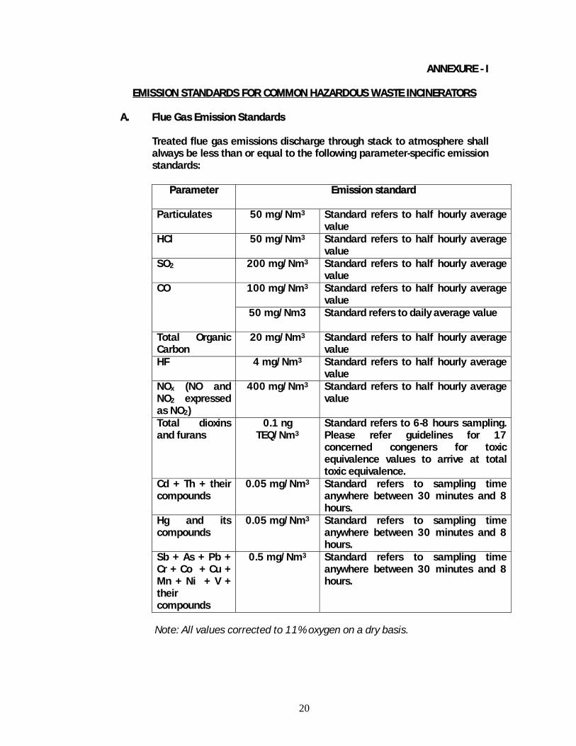
ANNEXURE - I
EMISSION STANDARDS FOR COMMON HAZARDOUS WASTE INCINERATORS
A. Flue Gas Emission Standards Treated flue gas emissions discharge through stack to atmosphere shall
always be less than or equal to the following parameter-specific emission standards:
Parameter Emission standard
Particulates 50 mg/Nm3 Standard refers to half hourly average
value HCl 50 mg/Nm3 Standard refers to half hourly average
value SO2 200 mg/Nm3 Standard refers to half hourly average
value 100 mg/Nm3 Standard refers to half hourly average
value CO
50 mg/Nm3 Standard refers to daily average value
Total Organic Carbon
20 mg/Nm3 Standard refers to half hourly average value
HF 4 mg/Nm3 Standard refers to half hourly average value
NOx (NO and NO2 expressed as NO2)
400 mg/Nm3 Standard refers to half hourly average value
Total dioxins and furans
0.1 ng TEQ/Nm3
Standard refers to 6-8 hours sampling. Please refer guidelines for 17 concerned congeners for toxic equivalence values to arrive at total toxic equivalence.
Cd + Th + their compounds
0.05 mg/Nm3 Standard refers to sampling time anywhere between 30 minutes and 8 hours.
Hg and its compounds
0.05 mg/Nm3 Standard refers to sampling time anywhere between 30 minutes and 8 hours.
Sb + As + Pb + Cr + Co + Cu + Mn + Ni + V + their compounds
0.5 mg/Nm3 Standard refers to sampling time anywhere between 30 minutes and 8 hours.
Note: All values corrected to 11% oxygen on a dry basis.

21
B. Operating Standards:
I. All the facilities shall be designed to achieve a minimum temperature of 1100°C in secondary combustion chamber and with a gas residence time in secondary combustion chamber not less than 2 (two) seconds.
II. The incineration facilities after initial operation of minimum one year,
as per the guidelines and standards, can submit a proposal for relaxation in temperature and retention time requirement if it can be demonstrated that the flue gas standards and operation standards can be complied with at lower temperatures and residence times. The State Pollution Control Board / Pollution Control Committee, upon successful demonstration of compliance with flue gas standards by the facility, can recommend the proposal made by the incineration facility for relaxation in temperature and residence time, but in any case not less than 950 °C and 1.5 seconds, for the consideration and approval of the Central Board.
III. Incineration plants shall be operated (combustion chambers) with such temperature, retention time and turbulence, so as to achieve Total Organic Carbon (TOC) content in the slag and bottom ashes less than 3%, or their loss on ignition is less than 5% of the dry weight of the material.
IV. Guidelines published by the Central Board from time to time for common incineration facilities shall be referred for implementation.
V. All the project proposals submitted for establishment of the common
incineration facilities shall be examined and cleared by the Task Force constituted by the Central Board.
VI. Notification of compliance: The operator of the incinerator shall
undertake comprehensive performance test. Within 90 days of completion of comprehensive performance test, the operator shall issue a notification of compliance documenting compliance or non-compliance, as the case may be, for public information / notice.