hawke’s bay waterway guidelines · hawke‟s bay waterway guidelines erosion and sediment control...
TRANSCRIPT

Hawke‟s Bay Waterway Guidelines Erosion and Sediment Control 20090406 i
Hawke’s Bay Waterway Guidelines
Erosion and Sediment Control
Prepared by: Earl Shaver, Aqua Terra International Ltd
Reviewed by: Gary Clode, Manager - Engineering
Acknowledgement This document for the Hawke‟s Bay Region is based on the Auckland Regional Council‟s Technical Publication No. 90 “Erosion and Sediment Control Guidelines for Land Disturbing Activities”. The ARC gave permission to use their document and that permission is greatly appreciated. Modifications to the ARC document have been made so there will be some differences to the ARC approach to account for advances in practice design and to reflect local conditions.
Note This document is a living document and may be reviewed from time to time as industry standards change and best practice evolves. Please contact Hawke‟s Bay Regional Council to ensure the latest version is used.
April 2009
ISBN NO 1-877405-35-3 HBRC Plan Number 4109
© Copyright: Hawke’s Bay Regional Council

Hawke‟s Bay Waterway Guidelines Erosion and Sediment Control 20090406 ii
Hawke‟s Bay Waterway Guidelines Erosion and Sediment Control 20090406 iii
Contents 1 Overview of the guidelines ................................................................................. 1
1.1 Intent of These Guidelines .......................................................................... 1 1.2 How These Guidelines Work ....................................................................... 1 1.3 Erosion and Sediment Control in the Hawke‟s Bay Region ......................... 2 1.4 Current Legislation: When is a Resource Consent Required? ..................... 3 1.5 When is Erosion and Sediment Control Required? ...................................... 3 1.6 Hawke‟s Bay Soils: The Prime Importance of Erosion Control..................... 4
2 Basic erosion facts ............................................................................................. 6 2.1 Types of Erosion ......................................................................................... 6 2.2 Factors Influencing the Erosion Process ..................................................... 9
3 Principles to Follow .......................................................................................... 11 3.1 Minimise Disturbance ................................................................................ 11 3.2 Stage Construction .................................................................................... 11 3.3 Protect Steep Slopes ................................................................................ 11 3.4 Protect Watercourses ................................................................................ 11 3.5 Stabilise Exposed Areas Rapidly ............................................................... 12 3.6 Install Perimeter Controls .......................................................................... 12 3.7 Employ Detention Devices ........................................................................ 12 3.8 Get Educated ............................................................................................ 12 3.9 Make Sure the Plan Evolves ..................................................................... 12 3.10 Assess and Adjust ..................................................................................... 13
4 Types of Land Disturbing Activities ................................................................... 14 4.1 Trenching .................................................................................................. 14 4.2 Works Within a Watercourse ..................................................................... 14 4.3 Cleanfills ................................................................................................... 15 4.4 Small Sites and Permitted Activities .......................................................... 15 4.5 Earthworks ................................................................................................ 16 4.6 Roading .................................................................................................... 16 4.7 Quarries and Vegetation Removal ............................................................ 17
5 Erosion Control Practices ................................................................................. 18 5.1 Runoff diversion channel ........................................................................... 19 5.2 Contour drain ............................................................................................ 22 5.3 Benched slope .......................................................................................... 24 5.4 Rock check dams ...................................................................................... 26 5.5 Top soil placement .................................................................................... 29 5.6 Revegetation ............................................................................................. 31 5.7 Hydroseed................................................................................................. 34 5.8 Mulching ................................................................................................... 36 5.9 Turfing ....................................................................................................... 39 5.10 Erosion control matting ............................................................................. 41 5.11 Stabilised construction entrance ................................................................ 45 5.12 Pipe or Flume drop structure ..................................................................... 47 5.13 Level spreader .......................................................................................... 50 5.14 Surface roughening ................................................................................... 53
6 Sediment Control Practices .............................................................................. 55 6.1 Sediment Retention Pond ......................................................................... 56 6.2 Flocculation ............................................................................................... 67 Comments ........................................................................................................... 71 6.3 Silt Fence .................................................................................................. 74 6.4 Super silt fence ......................................................................................... 77 6.5 Straw Bale Barrier ..................................................................................... 80 6.6 Stormwater Inlet Protection ....................................................................... 82 6.7 Decanting earth bund ................................................................................ 85

Hawke‟s Bay Waterway Guidelines Erosion and Sediment Control 20090406 iv
6.8 Decanting topsoil bund .............................................................................. 88 6.9 Sump/sediment pit .................................................................................... 89
7 Quarries ........................................................................................................... 91 7.1 Road Access ............................................................................................. 91 7.2 Stormwater................................................................................................ 91 7.3 Overburden Disposal ................................................................................ 92 7.4 Stockpile Areas ......................................................................................... 92 7.5 Rehabilitation of Worked Out Areas .......................................................... 92 7.6 Riparian Protection Areas ......................................................................... 93 7.7 Maintenance Schedule for Erosion and Sediment Control or Treatment Structures ............................................................................................................ 93
Appendix A .............................................................................................................. 94

Hawke‟s Bay Waterway Guidelines Erosion and Sediment Control 20090406 1
1 Overview of the guidelines
1.1 Intent of These Guidelines These Guidelines have three main objectives: 1. To provide users, ranging from those directly associated with various Land
Disturbing Activities to interest groups, with a series of comprehensive guidelines for erosion and sediment control for land disturbing activities by:
outlining the principles of erosion and sediment control and the sediment transfer process; and
providing a range of erosion and sediment control practices that can be implemented on various Land Disturbing Activities.
2. To detail the rules in the Hawke‟s Bay Regional Council's Regional Resource
Management Plan which defines the permitted activity and restricted discretionary status of Rules 7 and 8 relating to Vegetation Clearance and Soil Disturbance Activities.
3. To minimise adverse environmental effects of Vegetation Clearance and Soil Disturbance Activities through appropriate use and design of erosion and sediment control techniques.
1.2 How These Guidelines Work These Guidelines overview the erosion and sediment controls that can be used when undertaking various Vegetation Clearance and Soil Disturbing Activities and are known as Technical Guidelines AM08/13 related to Guidelines for Waterways and titled Erosion and Sediment control Guidelines for the Hawke‟s Bay Region. These Guidelines focus on the principles and practices of erosion and sediment control recommended for various Vegetation Clearance and Soil Disturbing Activities. While not providing the full details of the Resource Consent application process, they refer to the process and it is anticipated that they will form an integral part of the consent process. The Guidelines should be used during the development of an Erosion and Sediment Control Plan for a project, and must also be used as part of operating under the conditions of an approved consent. These Guidelines are split into two main sections, Principles and Practices. The Principles section outlines ten critical elements that need to be considered when developing an Erosion and Sediment Control Plan for any Vegetation Clearance and Soil Disturbing Activity. These ten elements are referred to as the Ten Commandments of Erosion and Sediment Control. The Practices section covers on-site practices to be used when implementing the Ten Commandments. In most circumstances, a range of practices will need to be used on any Vegetation Clearance and Soil Disturbing Activity within the Hawke‟s Bay Region. Standard symbols for erosion and sediment controls are used in Sections 5 and 6.

Hawke‟s Bay Waterway Guidelines Erosion and Sediment Control 20090406 2
1.3 Erosion and Sediment Control in the Hawke‟s Bay Region Hundreds of hectares of land are stripped of vegetation or laid bare each year around the Hawke‟s Bay Region for the construction of subdivisions, roads, landfills and other developments. Without protection measures, the transformation of this land can result in accelerated on-site erosion and greatly increased sedimentation of waterways, estuaries and harbours. Significant quantities of sediment are discharged from bare earth surfaces where appropriate erosion and sediment control measures are not implemented. Various New Zealand studies indicate there is a 10 to 100 times increase in sediment yield from construction sites compared with pastoral land, while data from the United States suggests that there may be up to 1000 times the sediment yield from disturbed sites during construction compared with permanent forest cover. One study in the latter part of the 1990‟s in the Auckland Region stated that during one earthworks season, 1000 ha of bare land was worked. If left unprotected this could have resulted in a discharge of up to 66,000 tonnes of sediment/year to aquatic receiving environments. The adverse ecological effects caused by sediment in waterways include:
Modified or destroyed instream values.
Modified estuarine and coastal habitats.
Smothering and abrading of fauna and flora.
Changes in food sources and interruption of life cycles.
There is often a total change to instream communities. Recovery times from the impacts of sediment deposition are more likely to be measured in years rather than months. In addition to ecological changes, there may be damage to water pumps and other structures; the quality of water supplies usually diminishes; localised flooding can occur and there is a loss of aesthetic appeal. The Resource Management Act 1991 (RMA) establishes the Hawke‟s Bay Regional Council's statutory responsibilities for resource management. The purpose of the RMA is to promote the sustainable management of natural and physical resources. `Sustainable management' is defined in Section 5 of the Act as: `managing the use, development and protection of natural and physical resources in a way or at a rate, which enables people and communities to provide for their social, economic, and cultural wellbeing and for their health and safety while:
(a) sustaining the potential of natural and physical resources (excluding minerals) to meet the reasonably foreseeable needs of future generations; and
(b) safeguarding the life supporting capacity of air, water, soil and ecosystems; and
(c) avoiding, remedying or mitigating any adverse effects of activities on the environment.'
Hawke‟s Bay Waterway Guidelines Erosion and Sediment Control 20090406 3
1.4 Current Legislation: When is a Resource Consent Required?
The legal basis for requiring a Land Use Consent for Land Disturbing Activities is the Hawke‟s Bay Regional Council's Regional Resource Management Plan which defines the permitted activity and restricted discretionary status of Rules 7 and 8 relating to Vegetation Clearance and Soil Disturbance Activities. The Plan's rules apply to Vegetation Clearing and Soil Disturbing Activities including earthworks, vegetation removal, roading, tracking, trenching and quarries. A copy of Rules 7 and 8 can be found in Appendix A of these Guidelines. It is important to note that the rules are valid at the time of publishing these Guidelines but are subject to change. Contact the Hawke‟s Bay Regional Council to confirm the status of the rules contained within these Guidelines before making a decision based upon them.
1.5 When is Erosion and Sediment Control Required?
Permitted and Restricted Discretionary activities relate to the following:
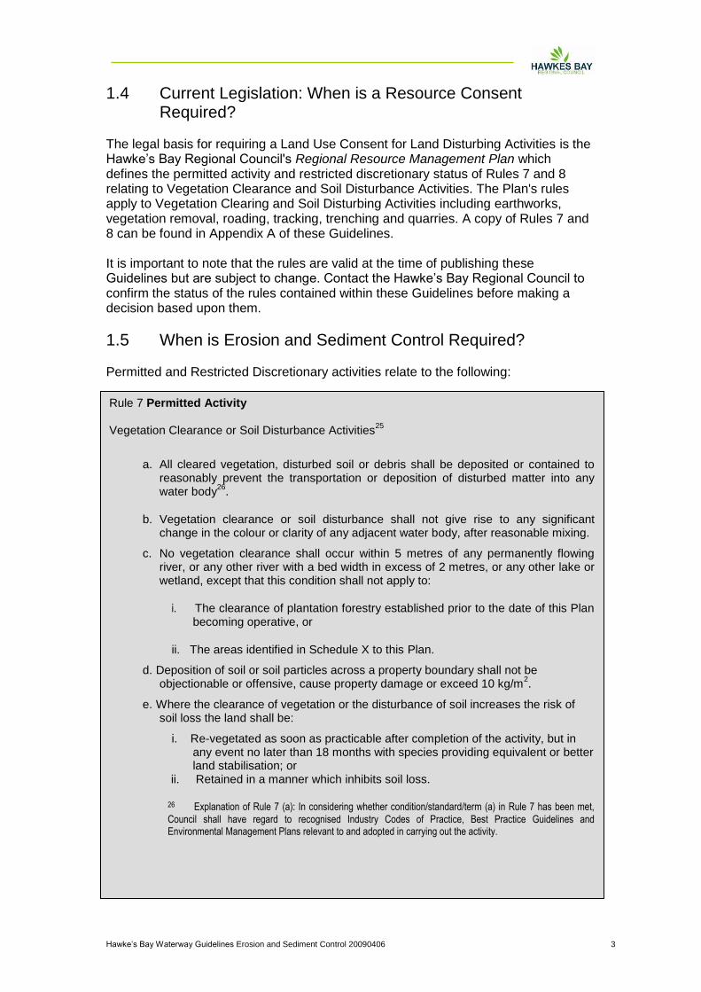
Rule 7 Permitted Activity Vegetation Clearance or Soil Disturbance Activities
25
a. All cleared vegetation, disturbed soil or debris shall be deposited or contained to reasonably prevent the transportation or deposition of disturbed matter into any water body
26.
b. Vegetation clearance or soil disturbance shall not give rise to any significant change in the colour or clarity of any adjacent water body, after reasonable mixing.
c. No vegetation clearance shall occur within 5 metres of any permanently flowing river, or any other river with a bed width in excess of 2 metres, or any other lake or wetland, except that this condition shall not apply to:
i. The clearance of plantation forestry established prior to the date of this Plan becoming operative, or
ii. The areas identified in Schedule X to this Plan.
d. Deposition of soil or soil particles across a property boundary shall not be objectionable or offensive, cause property damage or exceed 10 kg/m
2.
e. Where the clearance of vegetation or the disturbance of soil increases the risk of soil loss the land shall be:
i. Re-vegetated as soon as practicable after completion of the activity, but in any event no later than 18 months with species providing equivalent or better land stabilisation; or
ii. Retained in a manner which inhibits soil loss. 26 Explanation of Rule 7 (a): In considering whether condition/standard/term (a) in Rule 7 has been met,
Council shall have regard to recognised Industry Codes of Practice, Best Practice Guidelines and Environmental Management Plans relevant to and adopted in carrying out the activity.
Hawke‟s Bay Waterway Guidelines Erosion and Sediment Control 20090406 4
1.6 Hawke‟s Bay Soils: The Prime Importance of Erosion Control
The Hawke‟s Bay region has many highly valued environments due to its extensive variation in landform and coastline. It has 350 km of coastline and goes inland to the Ruataniwha and Kaweka mountain ranges. The region‟s coast has many beaches supporting fishing, diving, swimming and other water sports and receational activities. Inland, Lake Waikaremoana and Lakes Waikareiti and Tutira provide habitats for flora and fauna and are popular recreational areas. Further, the region‟s seven major rivers and many tributaries provide clear water for the likes of trout, and whitebait. Significant wetland areas abound and include Pekapeka Swamp and Whakaki. These environments are sensitive to use and change and implementation of erosion
Rule 8 Restricted Discretionary Activity Vegetation clearance or soil disturbance activities, which do not meet the conditions in Rule 7
26.
a. The conditions, standards or terms which the activity cannot comply with, and the related environmental effects.
b. Monitoring and reporting requirements. c. Duration of consent. d. Review of consent conditions.
Applications may be considered without notification, without the need to obtain the
written approval of affected persons.
Vegetation clearance and soil disturbance exclude:
The normal maintenance of legally established structures, roads, tracks, railway lines and river beds. The clearance of grasses, forest thinning, and agricultural and horticultural crops. The clearance of isolated or scattered regrowth on productive pasture. The clearance of any indigenous vegetation understorey beneath plantation forests. The clearance of noxious weeds covered by the Regional Plant Pest Management Strategy prepared under the Biosecurity Act, 1993. Non-motorised soil disturbance activities. Thrusting, boring, trenching or mole ploughing associated with cable or pipe laying or a network utility operation. Soil disturbance undertaken by a mine or quarry operation which either had a valid mining licence at the date the Proposed Regional Resource Management Plan was publicly notified (15 April 2000) or is lawfully established. Cultivation and grazing. Foundations works for structures. Construction and maintenance of fences and drains.
26
Explanation of Rule 7 (a): In considering whether condition/standard/term (a) in Rule 7 has been met, Council shall have regard to recognised Industry Codes of Practice, Best Practice Guidelines and Environmental Management Plans relevant to and adopted in carrying out the activity.
Note: 10 kg/m
2 of dry soil is equivalent to 5 mm depth assuming a specific gravity of 2
kg/litre.
Hawke‟s Bay Waterway Guidelines Erosion and Sediment Control 20090406 5
and sediment control during construction is critical to maintenance of resource values. Hawke‟s Bay has a diverse range of soil types from deep, free draining gravels to heavier silts and loams. In addition, Hawke‟s Bay has some of the highest rainfall variabilities in New Zealand. These factors, when coupled with earth disturbance, have a high potential for excess sedimentation to impact on downstream aquatic resources. The variable size of soil particles typical of Hawke‟s Bay geology impacts on the effectiveness of erosion and sediment controls. The fine clays, once mobilised, take a much longer time to settle than the coarser sand and silt material. Bigger, better or more numerous sediment control measures may therefore not be very effective in limiting off-site transfer of fine sediments. Most effort should be put into preventing sediment generation in the first instance. That is, into erosion control rather than sediment control. Erosion control techniques include the following:
Revegetation
Minimisation of earthworks
Timing
Staging of earthworks operations
Other measures such as the use of chemical treatment of runoff may also be necessary in some circumstances.
Hawke‟s Bay Waterway Guidelines Erosion and Sediment Control 20090406 6
2 Basic erosion facts
2.1 Types of Erosion Erosion is the process whereby the land surface is worn away by the action of water, wind, ice or other geological processes. The resultant displaced material is known as sediment. Sedimentation is the deposition of this eroded material. Accelerated erosion, caused primarily by human development activities, is generally much more rapid than natural erosion. The basic erosion process is detachment, transport and deposition (sedimentation), where water is the usual eroding agent and transport medium, through raindrop impact and overland flow energy. Water dislodges exposed soil particles and transports them downslope. Runoff and streamflow transport the eroded soil particles to the final receiving environment where sedimentation occurs. There are seven main types of erosion associated with land disturbing activities.
Splash erosion
Sheet erosion
Rill erosion
Gully erosion
Tunnel erosion
Channel erosion
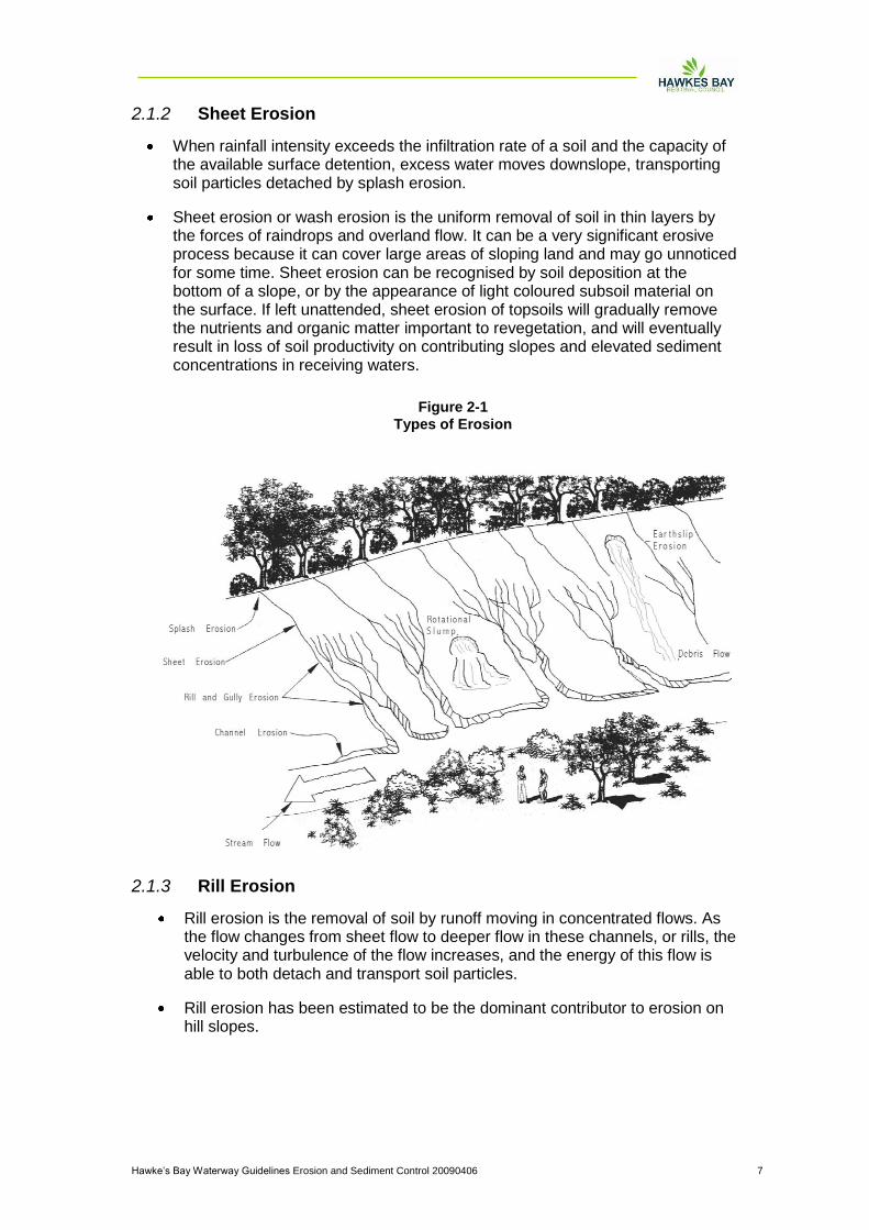
Mass movement These are outlined below and also shown in Figure 2-1.
2.1.1 Splash Erosion
Soil erosion is a mechanical process that requires energy. Much of this energy is supplied by falling rain drops.
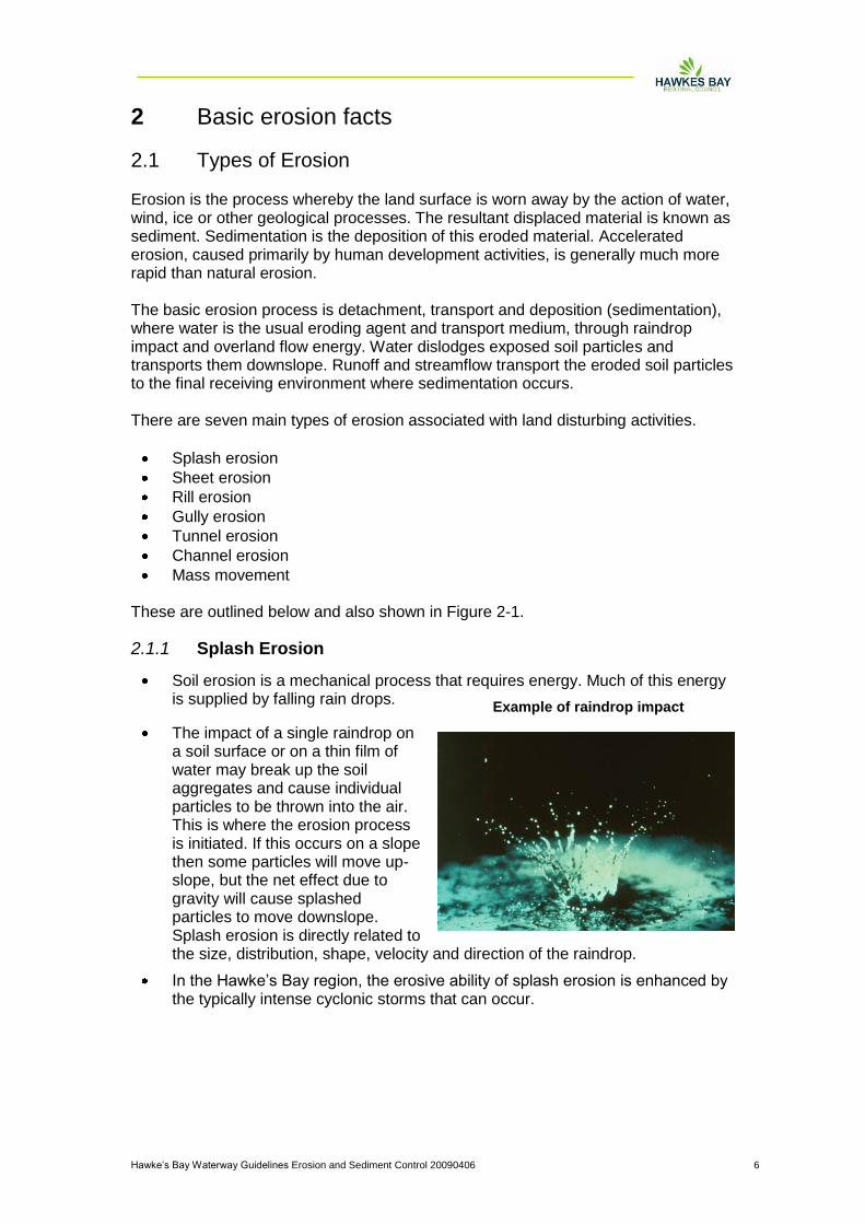
The impact of a single raindrop on a soil surface or on a thin film of water may break up the soil aggregates and cause individual particles to be thrown into the air. This is where the erosion process is initiated. If this occurs on a slope then some particles will move up-slope, but the net effect due to gravity will cause splashed particles to move downslope. Splash erosion is directly related to the size, distribution, shape, velocity and direction of the raindrop.
In the Hawke‟s Bay region, the erosive ability of splash erosion is enhanced by the typically intense cyclonic storms that can occur.
Example of raindrop impact
Hawke‟s Bay Waterway Guidelines Erosion and Sediment Control 20090406 7
2.1.2 Sheet Erosion
When rainfall intensity exceeds the infiltration rate of a soil and the capacity of the available surface detention, excess water moves downslope, transporting soil particles detached by splash erosion.
Sheet erosion or wash erosion is the uniform removal of soil in thin layers by the forces of raindrops and overland flow. It can be a very significant erosive process because it can cover large areas of sloping land and may go unnoticed for some time. Sheet erosion can be recognised by soil deposition at the bottom of a slope, or by the appearance of light coloured subsoil material on the surface. If left unattended, sheet erosion of topsoils will gradually remove the nutrients and organic matter important to revegetation, and will eventually result in loss of soil productivity on contributing slopes and elevated sediment concentrations in receiving waters.
2.1.3 Rill Erosion
Rill erosion is the removal of soil by runoff moving in concentrated flows. As the flow changes from sheet flow to deeper flow in these channels, or rills, the velocity and turbulence of the flow increases, and the energy of this flow is able to both detach and transport soil particles.
Rill erosion has been estimated to be the dominant contributor to erosion on hill slopes.
Figure 2-1
Types of Erosion
Hawke‟s Bay Waterway Guidelines Erosion and Sediment Control 20090406 8
2.1.4 Gully Erosion
Gully erosion is the removal of soil by running water resulting in the formation of channels greater than 300 mm deep. Gullies can be distinguished from rills when normal agricultural tillage operations cannot obliterate them.
The following are the processes which act in the formation of gullies.
Waterfall erosion at the head of the gully
Channel erosion
Raindrop splash
Diffuse flow from the side of the gully or from seepage
Slides or mass movement of soil within the gully.
A gully may develop and grow rapidly and their formation may generate a considerable amount of erosion. Therefore, their prevention and remediation is vital for erosion control.
2.1.5 Tunnel Erosion
Tunnel erosion, or piping, is the removal of subsurface soil by subsurface water while the surface soil remains relatively intact. This produces long cavities beneath the ground surface, which may enlarge until the soil surface is no longer supported, at which point the surface may collapse forming a circular hole, sometimes referred to as a `tomo'. Such erosion tunnels may range in size from a few centimetres to several metres in diameter and typically form a series along the surface above a tunnel.
2.1.6 Channel Erosion
The erosion of ephemeral or perennial channels results from direct action of concentrated flow when the velocity or volume of flow in a stream increases. Natural channels adjust over time to the volume and velocity of runoff that normally occurs in the catchment. Channel erosion occurs by scouring or undercutting of the stream bank below the water surface and generally happens during medium to high flows.
Channel erosion is a major contributor to sedimentation in metropolitan areas. High flows in stream channels occur more frequently once a catchment has been urbanised, eroding stream banks and enlarging the channel. For example, an Auckland study showed a three-fold channel widening after 85% of the catchment had been urbanised (Herald, 1989).
2.1.7 Mass Movement
Mass movement is the erosion of soil or rock by gravity-induced collapse. It is usually triggered by groundwater pressure after heavy rain, but can also have other causes, notably streams undercutting the base of a slope or earthworks. Movement can be either rapid and near instantaneous (landslides, avalanches, debris flows), or slow and intermittent (earthflows and slumps). Earth and soil slip movement are also often noted after the removal of vegetation from critical slopes associated with Land Disturbing Activities. These slopes need to be identified before development starts and should be avoided wherever practicable.

Hawke‟s Bay Waterway Guidelines Erosion and Sediment Control 20090406 9
Mass movement can cause major problems on earthworks sites and geotechnical investigations should be undertaken where possible to avoid critical slopes or allow for the prevention of such erosion.
2.2 Factors Influencing the Erosion Process
The main factors influencing soil erosion are climate, soil characteristics, topography, ground cover and evapotranspiration.
2.2.1 Climate
Climate affects erosion potential both directly and indirectly. The direct relationship arises from the action of rain - a driving force of erosion - where raindrops dislodge soil particles and runoff carries them away. The annual pattern of rainfall and temperature change, by and large, determines the extent and growth rate of vegetation. This is critical, because vegetation is currently the most important form of erosion control used on Land Disturbing Activities.
The Hawke‟s Bay Region receives from 1400 - 2000 mm of rainfall annually, with average monthly rainfalls being greatest throughout the winter period. Summer has the greatest rainfall variability, some summers being very dry, others wet.
Intense cyclonic storms during summer also create many erosion problems, with a large amount of rain falling within a short time period. Erosion and sediment control for all land disturbing activities must be planned accordingly.
2.2.2 Soil Characteristics
Four soil characteristics are important in determining soil erodibility:
Soil texture refers to the particle sizes making up a particular soil and their relative proportions. Sand, silt and clay are the three major soil particle classes. Hawke‟s Bay soils tend to be highly variable and range from extremely fine to coarse. If there is significant clay content, it will create difficulty as once mobilised, it is very difficult to settle out. This is due to the small nature of individual particles and the tendency for clay particles to repel each other, thus keeping them in suspension.
Organic matter improves soil structure and increases permeability, water holding capacity and soil fertility.
Soil permeability refers to the ability of the soil to allow air and water to move through the soil. Soils with a higher permeability produce less runoff at a lower rate than soils with low permeability. Engineered fills have a very low permeability, resulting in increased levels of potentially erosive runoff.
Soil structure is the degree that soil particles are arranged into aggregates. A granular structure is the most desirable in both agricultural and erosion control terms. When the soil surface is compacted or crusted, water tends to run off rather than infiltrate. Erosion potential increases with increased runoff.
2.2.3 Topography
Slope length and slope angle are critical factors in erosion potential because they play a large part in determining the velocity of runoff. Long continuous slopes allow runoff to increase velocity and to concentrate flow. This produces rill and gully erosion.

Hawke‟s Bay Waterway Guidelines Erosion and Sediment Control 20090406 10
The shape of a slope also has a major bearing on erosion potential. The base of a slope is more susceptible to erosion than the top because runoff arriving there is moving faster and is more concentrated. However, deposition may occur at the base of concave slopes where slope angle diminishes.
2.2.4 Ground Cover
Ground cover includes vegetation and surface treatment such as mulches and geotextiles. Vegetation is without question the most effective long term form of erosion control for protecting surfaces that have been disturbed. Vegetation shields the soil surface from the impact of falling rain, slows the velocity of runoff, holds soil particles in place and maintains the soil's capacity to absorb water.
2.2.5 Evapotranspiration
The Hawke‟s Bay region has a fairly frequent rainfall during the winter, but due to high evapotranspiration and a minimum of rainfall in the summer period, soil moisture levels are often so low that irrigation or watering is needed to achieve the moisture levels needed for plant growth. Evapotranspiration rates and the number of days of soil moisture deficit vary across the region. Careful consideration needs to be given to evapotranspiration when attempting to establish a vegetative cover and prevent erosion.

Hawke‟s Bay Waterway Guidelines Erosion and Sediment Control 20090406 11
3 Principles to Follow
3.1 Minimise Disturbance Fit land development to land sensitivity. Some parts of a site should never be worked and others need very careful working. Watch out for and avoid areas that are wet (streams, wetlands, springs), have steep or fragile soils or are conservation sites or features. Bear in mind the minimum earthworks strategy (low impact design) - ideally, only clear areas required for structures or access. Show all Limits of Disturbance on the Erosion and Sediment Control Plan (E&SCP). On site, clearly show Limits of Disturbance using fences, signs and flags.
3.2 Stage Construction Carrying out bulk earthworks over the whole site maximises the time and area that soil is exposed and prone to erosion. "Construction staging", where the site has earthworks undertaken in small units over time with progressive revegetation, limits erosion. Careful planning is needed. Temporary stockpiles, access and utility service installation all need to be planned. Construction staging differs from sequencing. Sequencing sets out the order of construction to contractors. Detail both construction staging and sequencing in the E&SCP.
3.3 Protect Steep Slopes Existing steep slopes should be avoided. If clearing is absolutely necessary, runoff from above the site can be diverted away from the exposed slope to minimise erosion. If steep slopes are worked and need stabilisation, traditional vegetative covers like topsoiling and seeding may not be enough - special protection is often needed. Highlight steep areas on the E&SCP showing Limits of Disturbance and any works and areas for special protection.
3.4 Protect Watercourses Existing streams, watercourses and proposed drainage patterns need to be mapped. Clearing is not permitted adjacent to a watercourse unless the works have been approved by the Hawke‟s Bay Regional Council. Where undertaken, work that crosses or disturbs the watercourse should implement practices contained in the „Works in Waterways: Guidelines for the Hawke‟s Bay Region‟, which is a companion document to the Erosion and Sediment Control Guidelines.

Hawke‟s Bay Waterway Guidelines Erosion and Sediment Control 20090406 12
Map all watercourses and show Limits of Disturbance and protection measures; show all practices to be used to protect new drainage channels; and indicate crossings or disturbances and associated construction methods in the E&SCP
3.5 Stabilise Exposed Areas Rapidly The ultimate objective is to fully stabilise disturbed soils with vegetation after each stage and at specific milestones within stages. Methods are site specific and can range from conventional sowing through to straw mulching. Mulching is the most effective instant protection. Clearly define time limits for grass or mulch covers, outline grass rates and species and define conditions for temporary cover in the case of severe erosion or poor germination in the E&SCP.
3.6 Install Perimeter Controls Perimeter controls above the site keep clean runoff out of the worked area - a critical factor for effective erosion control. Perimeter controls can also retain or direct sediment laden runoff within the site. Common perimeter controls are diversion drains, silt fences and earth bunds. Detail the type and extent of perimeter controls in the E&SCP along with design parameters.
3.7 Employ Detention Devices Even with the best erosion and sediment practices, earthworks will discharge sediment laden runoff during storms. Along with erosion control measures, sediment retention structures are needed to capture runoff so sediment generated can settle out. Areas with fine grained soils means sediment retention ponds are often not highly effective for those areas. Ensure the other control measures used are appropriate for the project and adequately protect the receiving environment. Include sediment retention structure design specifications; detailed inspection and maintenance schedules of structures and conversion plans for permanent structures, in the E&SCP.
3.8 Get Educated A trained and experienced contractor is an important element of an E&SCP. These people are responsible for installing and maintaining erosion and sediment control practices. Critical on-site staff should go through an erosion and sediment control training programme that may be available either locally or elsewhere in New Zealand. Better knowledge can save project time and money, by allowing for identification of threatened areas early on and putting into place correct practices. Making arrangements for a pre-construction meeting, regular inspection visits (including a pre-wintering meeting), and final inspection is also important.
3.9 Make Sure the Plan Evolves

Hawke‟s Bay Waterway Guidelines Erosion and Sediment Control 20090406 13
An effective E&SCP is modified as the project progresses from bulk earthworks to developed individual lots. Factors such as weather, changes to grade and altered drainage can all mean changes to planned erosion and sediment control practices. Update the E&SCP to suit site adjustments in time for the pre-construction meeting and initial inspection of installed erosion and sediment controls, and make sure it is regularly referred to and available on site.
3.10 Assess and Adjust Inspect, Monitor and Maintain Control Measures Assessment of controls is especially important following a storm. A large or intense storm will leave erosion and sediment controls in need of repair, reinforcement or cleaning out. Repairing without delay reduces further soil loss and environmental damage. Assessment and adjustment is an important erosion and sediment control practice _ make sure it figures prominently in the E&SCP. Assign responsibility for implementing the E&SCP and monitoring control measures as the project progresses.

Hawke‟s Bay Waterway Guidelines Erosion and Sediment Control 20090406 14
4 Types of Land Disturbing Activities
The following are the main types of Land Disturbing Activities undertaken in the Hawke‟s Bay region and these are discussed in these Guidelines.
Trenching
Watercourse works
Cleanfills
Small sites and permitted activities
Earthworks
Roading
Quarries and vegetation removal The following is a brief summary of key considerations for minimising adverse environmental effects of these activities that are not found in the detailed description of erosion and sediment control measures in Part B.
4.1 Trenching Trenching, usually for installing utility services, often happens towards the end of the bulk earthworks phase of a project. The following points need to be considered when trenching.
The project needs to be undertaken in appropriately sized stages such that the area exposed can be fully stabilised within an acceptable time frame.
If trenching impacts on existing erosion and sediment control measures that are part of the overall development, those measures should be reinstated as soon as possible. Contingency measures should be put in place until the original measures are reinstated or replaced.
All trenching operators working within a larger site must be familiar with the overall Erosion and Sediment Control Plan for the site and must comply with this approved plan.
Independent erosion and sediment control measures detailed in these Guidelines should be employed for the trenching operation.
Topsoil and subsoils should be stockpiled separately adjacent to the trench so that at the completion of the operation, these soils can be replaced in the appropriate order and vegetation established.
When trenching through overland flow paths, give special consideration to the diversion of any flows, which may occur during trenching, as well as reinstating and stabilising the overland flow path.
4.2 Works Within a Watercourse Works within a watercourse should be avoided wherever possible, with all alternatives considered beforehand. Where watercourse works are unavoidable, they will create sedimentation downstream, so the following points should be carefully considered when undertaking these works.
Have all alternatives been considered?
Install a stabilised diversion so that works can be undertaken in the dry and reinstate the streamflow only after these areas have been appropriately

Hawke‟s Bay Waterway Guidelines Erosion and Sediment Control 20090406 15
stabilised. If a diversion is not a viable option, then ensure the alternative options are fully considered.
Carry out works during a dry time of the year when stream flows are low and the likelihood of a storm is low.
Keep the duration of works short.
Identify instream values so as to avoid critical periods such as fish spawning periods.
Consider the direct short and long term impacts of culverts or instream structures and install appropriately designed fish-pass provisions.
Be sure to inform all downstream users, for example water-users, of potential downstream sediment discharges
4.3 Cleanfills Cleanfills dispose of unwanted fill material which may contain some other material as in the definition of cleanfill provided in these Guidelines. Land Disturbing Activities associated with cleanfills range from haul roads and access areas to tip faces and dumping areas. Several controls are needed for adequate erosion and sediment control on such sites and the following points should be carefully considered when undertaking such operations:
The cleanfill operator needs to ensure that material being accepted for the cleanfill fits within the HBRC's definition. In cases where it doesn't, the operator must reject such loads, which will then need to be transported to an approved landfill.
Erosion and sediment controls should be installed in accordance with these Guidelines and appropriate maintenance undertaken.
As a cleanfill operation is considered to be a land disturbing activity, each operation should be assessed for any necessary consents.
Staging of cleanfill operations is critical and a programme of progressive stabilisation of all cleanfill sites should be part of each operation.
4.4 Small Sites and Permitted Activities After the bulk earthwork phase of an earthworks operation, individual developers start house construction. This is the phase of small site developments which is considered as a permitted activity. The cumulative impact from small sites is considered to be considerable and in some areas may cumulatively discharge as much sediment as the initial development itself. Often at this stage of the proposal, stormwater systems are in place and there are no, or minimal, erosion and sediment controls on the site. This results in sediment discharging through an efficient conveyance system (the stormwater system) directly to the receiving environment. The following points need to be considered when undertaking small site development:
Erosion and sediment controls should be installed either on an individual site-by-site basis or a combination of the sites, in accordance with these guidelines.
Stormwater runoff from small sites needs careful planning in terms of the location of roof downpipes so that runoff across bare sites does not scour soils.
Hawke‟s Bay Waterway Guidelines Erosion and Sediment Control 20090406 16
Areas of exposed soils should be stabilised upon completion of earthworks, including topsoil and subsoil stockpiles, lawn areas and accessways.
The site should be isolated from the subdivision's road system using silt fences to intercept flow from the site, with a Stabilised Construction Entrance (see Part B, Section 1.8) of to provide site entry and exit.
4.5 Earthworks Earthworks include a wide range of activities from cleanfilling operations (defined above) through to earthworks associated with industrial, commercial and residential developments. Earthworks have a major potential to generate large amounts of sediment, and if not controlled appropriately, can lead to large sediment discharges. Planning of these developments is critical to ensure that the activity is undertaken appropriately, and in a controlled manner to avoid unnecessary impacts on receiving environments. Section 3 outlines the critical features of an earthworks operation. The following are further key points contractors need to be aware of when undertaking earthworks operations.
It is important to comply with the specific requirements of the resource consent when undertaking earthworks operations.
Emphasis should be placed on erosion control, rather than sediment control, because preventing sediment generation is the best means of preventing sediment discharge from earthworks sites.
Always produce an Erosion and Sediment Control Plan (E&SCP) for an earthworks operation. Be sure that all parties involved with the operation, including subcontractors, are familiar with and have access to a current copy of this Plan.
Always update the E&SCP with major variations on the site and be sure these variations have the appropriate approvals. Keep this up-to-date version in the site office at all times.
Plan ahead and undertake consultation with necessary parties as required. Get approvals and start the operation early to avoid last minute delays and the need to keep working into the undesirable wetter months.
Install appropriate controls in accordance with the approved E&SCP and be sure that the design specifications are appropriate for the operation.
Install subsurface drainage as required (to an agreed methodology) to divert subsurface cleanwater past control structures and areas of disturbance as appropriate.
4.6 Roading Like trenching, the linear nature of roading poses challenges for erosion and sediment control. Measures need to be carefully planned to ensure controls are successful. Often the operation can be undertaken sequentially, stabilising worked areas as they are completed. This minimises the total sediment generating area of the proposal and helps prevent unnecessary road maintenance. The following are some key points to consider when working through a roading proposal.
Provide enough room for effective erosion and sediment control measures. Often the road corridor itself can involve the whole designation area and no
Hawke‟s Bay Waterway Guidelines Erosion and Sediment Control 20090406 17
room remains for such controls. Where space is a constraint, make sure that the erosion and sediment controls are approved and will give the necessary protection to downstream receiving environments.
Incorporate stormwater design into the E&SCP. This removes the need to revisit the area to install stormwater systems and the unnecessary extra earthworks that their construction would require.
Keep the areas of road corridor exposed at any one time to a limit that can be practically stabilised with hardfill or by vegetative means, to minimise the exposed area at risk.
When crossing watercourses, look for alternative routes and alternative designs and implement the option which provides the best environmental alternative.
Control all upslope catchment runoff, diverting clean water around or safely through the area of disturbance.
4.7 Quarries and Vegetation Removal Measures in these Guidelines are suitable for quarry and vegetation removal operations. However, the long term nature of many quarries and the clearfelling of whole catchments during vegetation removal operations mean that some special erosion and sediment control measures need to be implemented. Careful planning of such operations is thus critical. The key areas where attention is required are discussed in detail in Sections 5 and 6 of these Guidelines and should be read in conjunction with the other erosion and sediment controls also detailed. Vegetation removal projects are discussed in detail in another guideline.
Hawke‟s Bay Waterway Guidelines Erosion and Sediment Control 20090406 18
5 Erosion Control Practices Sections 5 and 6 outline minimum criteria for the design, construction and implementation of a range of erosion and sediment control measures commonly used on earthworks sites and on other land disturbing activities. These measures form one aspect of erosion and sediment control on any one site, and should always be used in conjunction with the measures outlined in Section 3 of these Guidelines. The most effective form of erosion control is to minimise the area of disturbance, retaining as much existing vegetation as possible. This is especially important on steep slopes or in the vicinity of watercourses, where no single measure will adequately control the erosion and transport of sediment, and where receiving environments may be highly sensitive. The criteria outlined are the minimum standard for each measure. Each land disturbing activity must be assessed on an individual basis, and in many cases higher standards may be required. For every practice, these Guidelines contain the following:
Definition,
Purpose,
Application,
Design/contruction specifications,
Comments, and
Maintenance Symbols are shown alongside main titles or within the pictures of controls.
Hawke‟s Bay Waterway Guidelines Erosion and Sediment Control 20090406 19
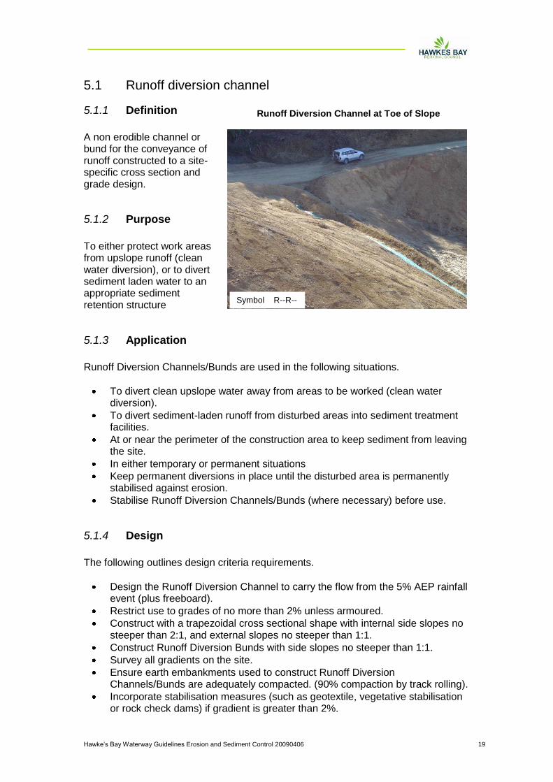
5.1 Runoff diversion channel
5.1.1 Definition
A non erodible channel or bund for the conveyance of runoff constructed to a site-specific cross section and grade design.
5.1.2 Purpose
To either protect work areas from upslope runoff (clean water diversion), or to divert sediment laden water to an appropriate sediment retention structure
5.1.3 Application
Runoff Diversion Channels/Bunds are used in the following situations.
To divert clean upslope water away from areas to be worked (clean water diversion).
To divert sediment-laden runoff from disturbed areas into sediment treatment facilities.
At or near the perimeter of the construction area to keep sediment from leaving the site.
In either temporary or permanent situations
Keep permanent diversions in place until the disturbed area is permanently stabilised against erosion.
Stabilise Runoff Diversion Channels/Bunds (where necessary) before use.
5.1.4 Design
The following outlines design criteria requirements.
Design the Runoff Diversion Channel to carry the flow from the 5% AEP rainfall event (plus freeboard).
Restrict use to grades of no more than 2% unless armoured.
Construct with a trapezoidal cross sectional shape with internal side slopes no steeper than 2:1, and external slopes no steeper than 1:1.
Construct Runoff Diversion Bunds with side slopes no steeper than 1:1.
Survey all gradients on the site.
Ensure earth embankments used to construct Runoff Diversion Channels/Bunds are adequately compacted. (90% compaction by track rolling).
Incorporate stabilisation measures (such as geotextile, vegetative stabilisation or rock check dams) if gradient is greater than 2%.
Runoff Diversion Channel at Toe of Slope
Symbol R--R--
Hawke‟s Bay Waterway Guidelines Erosion and Sediment Control 20090406 20
Incorporate a stable erosion-proof outfall (such as a level spreader) in order to reduce water velocities and prevent scour at the outlet.
Ensure the Runoff Diversion Channel/Bund outlet:
- functions with a minimum of erosion, - directs clean runoff onto an undisturbed/stabilised area, - directs flows containing sediment into a sediment retention structure, - is located in such a position that ideally suits the field conditions.
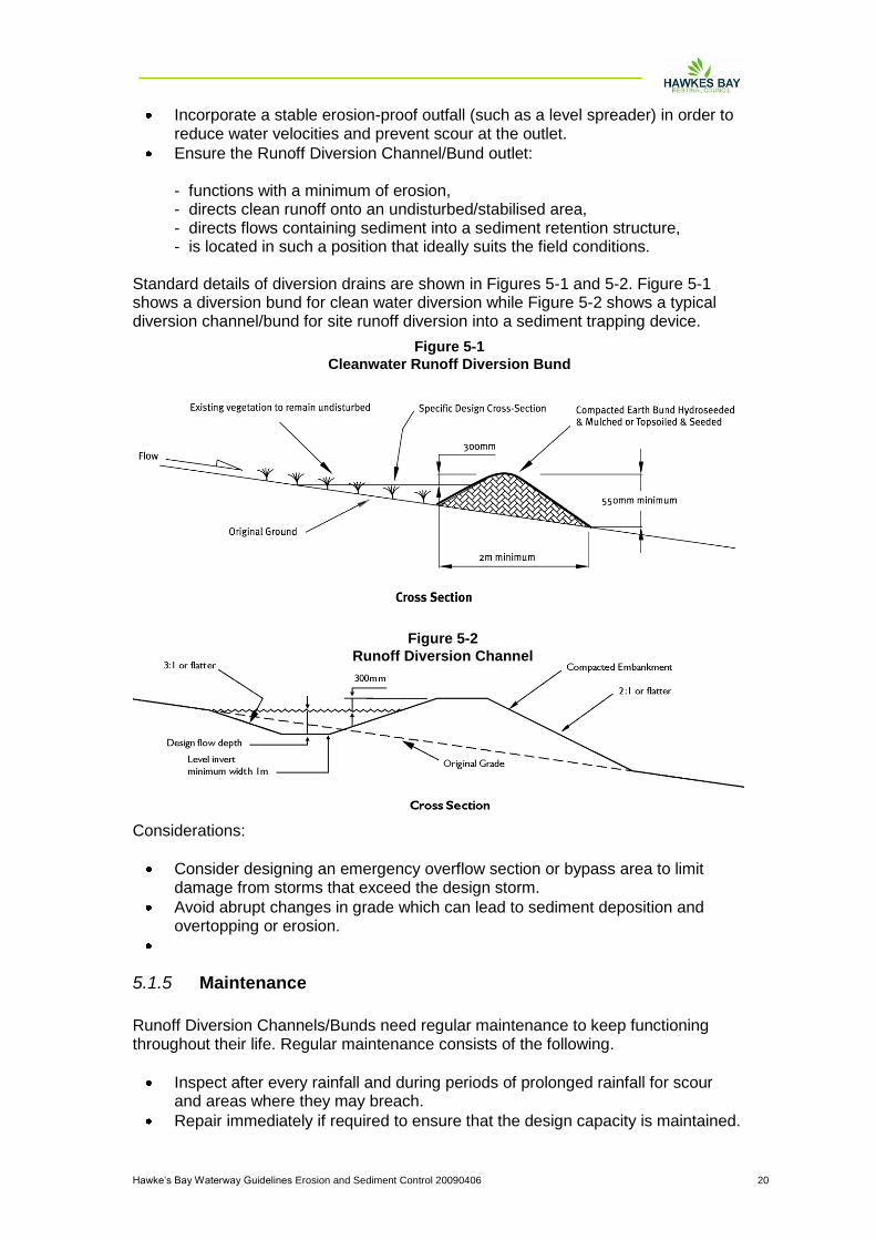
Standard details of diversion drains are shown in Figures 5-1 and 5-2. Figure 5-1 shows a diversion bund for clean water diversion while Figure 5-2 shows a typical diversion channel/bund for site runoff diversion into a sediment trapping device.
Considerations:
Consider designing an emergency overflow section or bypass area to limit damage from storms that exceed the design storm.
Avoid abrupt changes in grade which can lead to sediment deposition and overtopping or erosion.
5.1.5 Maintenance
Runoff Diversion Channels/Bunds need regular maintenance to keep functioning throughout their life. Regular maintenance consists of the following.
Inspect after every rainfall and during periods of prolonged rainfall for scour and areas where they may breach.
Repair immediately if required to ensure that the design capacity is maintained.
Figure 5-1
Cleanwater Runoff Diversion Bund
Figure 5-2
Runoff Diversion Channel

Hawke‟s Bay Waterway Guidelines Erosion and Sediment Control 20090406 21
Remove any accumulated sediment deposited in the Runoff Diversion Channel/Bund due to low gradients and velocities.
Carefully check outlets to ensure that these remain free from scour and erosion.
Hawke‟s Bay Waterway Guidelines Erosion and Sediment Control 20090406 22
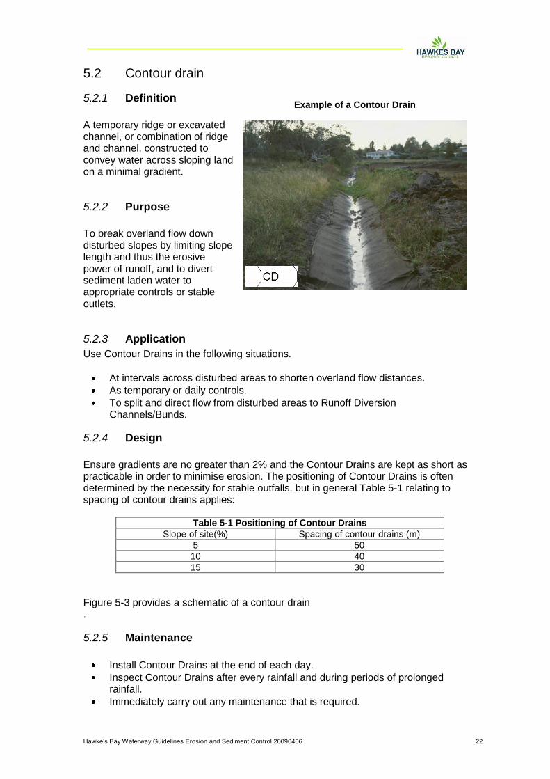
5.2 Contour drain
5.2.1 Definition
A temporary ridge or excavated channel, or combination of ridge and channel, constructed to convey water across sloping land on a minimal gradient.
5.2.2 Purpose
To break overland flow down disturbed slopes by limiting slope length and thus the erosive power of runoff, and to divert sediment laden water to appropriate controls or stable outlets.
5.2.3 Application
Use Contour Drains in the following situations.
At intervals across disturbed areas to shorten overland flow distances.
As temporary or daily controls.
To split and direct flow from disturbed areas to Runoff Diversion Channels/Bunds.
5.2.4 Design
Ensure gradients are no greater than 2% and the Contour Drains are kept as short as practicable in order to minimise erosion. The positioning of Contour Drains is often determined by the necessity for stable outfalls, but in general Table 5-1 relating to spacing of contour drains applies:
Table 5-1 Positioning of Contour Drains
Slope of site(%) Spacing of contour drains (m)
5 50
10 40
15 30
Figure 5-3 provides a schematic of a contour drain .
5.2.5 Maintenance
Install Contour Drains at the end of each day.
Inspect Contour Drains after every rainfall and during periods of prolonged rainfall.
Immediately carry out any maintenance that is required.
Example of a Contour Drain

Hawke‟s Bay Waterway Guidelines Erosion and Sediment Control 20090406 23
Figure 5-3
Contour Drain
Hawke‟s Bay Waterway Guidelines Erosion and Sediment Control 20090406 24
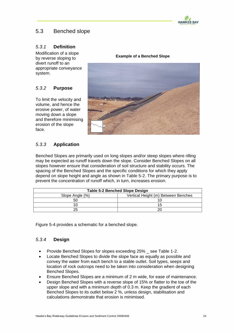
5.3 Benched slope
5.3.1 Definition
Modification of a slope by reverse sloping to divert runoff to an appropriate conveyance system.
5.3.2 Purpose
To limit the velocity and volume, and hence the erosive power, of water moving down a slope and therefore minimising erosion of the slope face.
5.3.3 Application
Benched Slopes are primarily used on long slopes and/or steep slopes where rilling may be expected as runoff travels down the slope. Consider Benched Slopes on all slopes however ensure that consideration of soil structure and stability occurs. The spacing of the Benched Slopes and the specific conditions for which they apply depend on slope height and angle as shown in Table 5-2. The primary purpose is to prevent the concentration of runoff which, in turn, increases erosion.
Table 5-2 Benched Slope Design
Slope Angle (%) Vertical Height (m) Between Benches
50 10
33 15
25 20
Figure 5-4 provides a schematic for a benched slope.
5.3.4 Design
Provide Benched Slopes for slopes exceeding 25% _ see Table 1-2.
Locate Benched Slopes to divide the slope face as equally as possible and convey the water from each bench to a stable outlet. Soil types, seeps and location of rock outcrops need to be taken into consideration when designing Benched Slopes.
Ensure Benched Slopes are a minimum of 2 m wide, for ease of maintenance.
Design Benched Slopes with a reverse slope of 15% or flatter to the toe of the upper slope and with a minimum depth of 0.3 m. Keep the gradient of each Benched Slopes to its outlet below 2 %, unless design, stabilisation and calculations demonstrate that erosion is minimised.
Example of a Benched Slope

Hawke‟s Bay Waterway Guidelines Erosion and Sediment Control 20090406 25
Keep the flow length along a Benched Slope to less than 250m unless design and calculations can demonstrate that erosion is minimised.
Divert surface water from the face of all cut and/or fill slopes of Benched Slopes by the use of Runoff Diversion Channels/Bunds except where: - the face of the slope is not subject to any concentrated flows of surface
water such as from natural drainage, channels or other concentrated discharge points, and
- the face of the slope is protected by special erosion control materials including, but not limited to, approved vegetative stabilisation practices, rip-rap, or other approved stabilisation methods.
Provide subsurface drainage where necessary to intercept seepage that would otherwise adversely affect slope stability or create excessively wet site conditions. Check the requirements of the city or district council.
Do not construct Benched Slopes close to property lines where they could endanger adjoining properties without adequately protecting such properties against sedimentation, erosion, slippage, settlement, subsidence or other related damages. Check the requirements of the city or district council.
Stabilise all disturbed areas.
5.3.5 Construction Specifications
Compact all fills to reduce erosion, slippage, settlement, subsidence, or other related problems.
Keep all Benched Slopes free of unconsolidated sediment during all phases of development.
Permanently stabilise all graded areas immediately on completion of grading.
Figure 5-3
Benched Slope Schematic

Hawke‟s Bay Waterway Guidelines Erosion and Sediment Control 20090406 26
5.4 Rock check dams
5.4.1 Definition
Small temporary dam constructed across a channel (excluding perennial watercourses), usually in series, to reduce flow velocity. May also help retain sediment.
5.4.2 Purpose
To reduce the velocity of concentrated flows, thereby reducing erosion of the channel. While trapping some sediment, they are not designed to be utilised as a sediment retention measure.
5.4.3 Application
This practice applies primarily to earthworks sites where it is necessary to slow velocity of flows in order to prevent erosion. Do not use Rock Check Dams in a perennial watercourse. Specific applications include the following.
Temporary channels which, because of their short length of service, are not suitable for non-erodible lining but still need some protection to reduce erosion.
Permanent channels which for some reason cannot receive a permanent non-erodible lining for an extended period of time.
Temporary or permanent channels which need protection during the establishment of a vegetative cover.
5.4.4 Design
Ensure the catchment in question has a contributory drainage area of less than 1.0 ha.
Direct all flows over the centre of the Rock Check Dam.
Construct each Rock Check Dam with a maximum centre height of 600 mm. Build the sides 200 mm higher than the centre to direct flows to the centre.
Do not use Rock Check Dams as a primary sediment trapping facility. Ensure that any sediment laden runoff passes through a sediment trapping device or devices before being discharged from the site.
Place a mix of 100 mm to 300 mm diameter washed rock to completely cover the width of the channel. In steeper catchments use larger sized rock (0.5 _ 1.0 m) on the downstream side of the Rock Check Dam.
Ensure rock batter slopes are no steeper than 2:1.
Stone Check Dam During Storm Conditions
Hawke‟s Bay Waterway Guidelines Erosion and Sediment Control 20090406 27
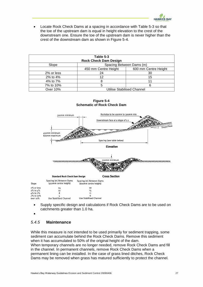
Locate Rock Check Dams at a spacing in accordance with Table 5-3 so that the toe of the upstream dam is equal in height elevation to the crest of the downstream one. Ensure the toe of the upstream dam is never higher than the crest of the downstream dam as shown in Figure 5-4.
Table 5-3 Rock Check Dam Design
Slope Spacing Between Dams (m)
450 mm Centre Height 600 mm Centre Height
2% or less 24 30
2% to 4% 12 15
4% to 7% 8 11
7% to 10% 5 6
Over 10% Utilise Stabilised Channel
Supply specific design and calculations if Rock Check Dams are to be used on catchments greater than 1.0 ha.
5.4.5 Maintenance
While this measure is not intended to be used primarily for sediment trapping, some sediment can accumulate behind the Rock Check Dams. Remove this sediment when it has accumulated to 50% of the original height of the dam. When temporary channels are no longer needed, remove Rock Check Dams and fill in the channel. In permanent channels, remove Rock Check Dams when a permanent lining can be installed. In the case of grass lined ditches, Rock Check Dams may be removed when grass has matured sufficiently to protect the channel.
Figure 5-4
Schematic of Rock Check Dam

Hawke‟s Bay Waterway Guidelines Erosion and Sediment Control 20090406 28
The area beneath the Rock Check Dams needs to be seeded and mulched or stabilised with appropriate geotextile immediately after removing the dams.
Hawke‟s Bay Waterway Guidelines Erosion and Sediment Control 20090406 29
5.5 Top soil placement
5.5.1 Definition
The placement of topsoil over a prepared subsoil prior to the establishment of vegetation.
5.5.2 Purpose
To provide a suitable soil medium for vegetative growth for erosion control while providing some limited short term erosion control capability by protecting subsoils and absorbing water.
5.5.3 Application
Top Soiling is recommended in the following situations.
Where the texture and/or the organic component of the exposed subsoil or parent material can not produce adequate vegetative growth.
Where the soil material is so shallow that the rooting zone is not deep enough to support plants or furnish continuing supplies of moisture and plant nutrients.
Where high quality turf and landscape plantings are to be established. Generally Top Soiling is combined with vegetation establishment and is not seen as an erosion control measure in itself. Top Soiling as a short term standalone erosion control measure is limited to sites with an average slope of less than 5 % with Contour Drains installed as per these Guidelines and for periods of less than two weeks only. Top Soiling alone will not provide sufficient erosion protection to allow sediment control measures to be removed. When staging within an earthworks operation, Top Soiling as a treatment in itself is not acceptable and other means of stabilisation such as revegetation will also be required.
5.5.4 Design
Not Applicable.
5.5.5 Construction Specifications
Once site shaping work has been completed, evenly spread a minimum of 100 mm of topsoil before revegetating. On steeper sites (over 25%), scarify the subsoils to a depth of a least 100 mm to ensure bonding between topsoil and subsoil before applying topsoil.

Hawke‟s Bay Waterway Guidelines Erosion and Sediment Control 20090406 30
Incorporate Surface Roughening into all Top Soiling operations in accordance with these Guidelines. In general topsoil has a beneficial effect in light rain because it can hold more moisture than the underlying clay material. However, during heavy rain, topsoil will become saturated and rill erosion and slumping can result. For this reason it is important to establish a full vegetative cover as soon as possible and retain all sediment retention facilities on the site until a vegetative cover is fully established.
5.5.6 Maintenance
Check the condition of the topsoil on a regular basis and regrade and/or replace where necessary so as to always maintain the 100 mm minimum depth of topsoil and surface roughening.
Hawke‟s Bay Waterway Guidelines Erosion and Sediment Control 20090406 31
5.6 Revegetation
5.6.1 Definition
The planting and establishment of quick growing and/or perennial vegetation to provide temporary and/or permanent stabilisation on exposed areas.
5.6.2 Purpose
Temporary Seeding is designed to stabilise the soil and to protect disturbed areas until permanent vegetation or other erosion control measures can be established. It may be used where the area to be stabilised is not yet up to final grade and requires further earthworks, but needs temporary stabilisation. Permanent Seeding is designed to permanently stabilise soil on disturbed areas to reduce sediment and runoff to downstream or off-site areas .
5.6.3 Application
5.6.3.1 Temporary Seeding
Use on any cleared or unvegetated areas which are subject to erosion and will not be earthworked for a period of 14 days or more. Temporary stabilisation is normally practised where the vegetative cover is required for less than one year. In some circumstances straw mulching may be used as an alternative (Section 5.1.8 of these Guidelines).
5.6.3.2 Permanent Seeding
This practice applies to any site where establishing permanent vegetation is important to protect bare earth. It may also be used on rough graded areas that will not be brought to final grade for a year or more.
5.6.4 Design
Not Applicable.
5.6.5 Construction Specifications
Site Preparation
Before seeding, install all required erosion and sediment control practices such as diversion channels and sediment retention structures. Grade the site as necessary to permit the use of conventional equipment for soil preparation, seeding and maintenance.
Seed Bed Preparation

Hawke‟s Bay Waterway Guidelines Erosion and Sediment Control 20090406 32
Prepare a good seed bed to ensure successful establishment of vegetation. Take care to ensure that the seed bed is free of large clods, rocks and other unsuitable material. Apply topsoil at a minimum depth of 100 mm to allow for a loose and friable soil surface.
Soil Amendments
Apply fertiliser as outlined in Table 5-4 of these Guidelines. This fertiliser application rate can be varied with the approval of the Hawke‟s Bay Regional Council. For large sites or unusual site conditions it is advisable to have soil fertility tests done. Some soils may require the addition of lime to improve pH.
Seeding
Apply seed at a mixture and rate as in Table 5-4 of these Guidelines. This seeding rate can be varied with approval from the Hawke‟s Bay Regional Council. Apply the seed uniformly and sow at the recommended rate. Seed that is broadcast must be covered by raking and then lightly tamped into place. If Hydroseeding is required, then it can be utilised in accordance with Section 5.1.7 of these Guidelines.
Mulching
When working on steep sites (greater than 25%) or during the winter period (generally between 30 April 30 and 1 October) mulching will need to be applied in accordance with Section 5.1.8 of these Guidelines immediately following seeding.
Irrigation
Adequate moisture is essential for seed germination and plant growth. Irrigation can be very helpful in establishing vegetation during dry or hot weather conditions or on adverse site conditions. Irrigation must be carefully controlled to prevent runoff and subsequent erosion. Inadequate or excessive irrigation can do more harm than good.
5.6.6 Maintenance
Reseed where seed germination is unsatisfactory or where erosion occurs. In the event of unsatisfactory germination after 30 April, the area will also require the application of Mulch in accordance with Part B Section 5.1.8 of these Guidelines. Depending on site conditions it may be necessary to irrigate, fertilise, oversow or re-establish plantings in order to provide vegetation for adequate erosion control. See Table 1.6 of these Guidelines for details of maintenance fertiliser applications. Protect all revegetated areas from traffic flows and other activities such as the installation of drainage lines and utility services.
Hawke‟s Bay Waterway Guidelines Erosion and Sediment Control 20090406 33
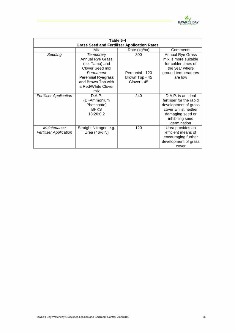
Table 5-4 Grass Seed and Fertiliser Application Rates
Mix Rate (kg/ha) Comments
Seeding Temporary Annual Rye Grass
(i.e. Tama) and Clover Seed mix
Permanent Perennial Ryegrass and Brown Top with a Red/White Clover
mix
300
Perennial - 120 Brown Top - 45
Clover - 45
Annual Rye Grass mix is more suitable for colder times of
the year where ground temperatures
are low
Fertiliser Application D.A.P. (Di-Ammonium
Phosphate) BPKS
18:20:0:2
240 D.A.P. is an ideal fertiliser for the rapid development of grass cover whilst neither damaging seed or
inhibiting seed germination
Maintenance Fertiliser Application
Straight Nitrogen e.g. Urea (46% N)
120 Urea provides an efficient means of
encouraging further development of grass
cover
Hawke‟s Bay Waterway Guidelines Erosion and Sediment Control 20090406 34
5.7 Hydroseed
5.7.1 Definition
The application of seed, fertiliser and paper or wood pulp with water in the form of a slurry, sprayed over the area to be revegetated.
5.7.2 Purpose
To establish vegetation quickly while providing a degree of instant protection from rain drop impact.
5.7.3 Application
This practice applies to any site where vegetation establishment is important for the protection of bare earth surfaces. For example:
Critical areas on the site prone to erosion such as steep slopes and Sediment Retention Pond batters.
Critical areas on the site that cannot be stabilised by conventional sowing methods.
Around watercourses or Runoff Diversion Channels where rapid establishment of a protective vegetative cover is required before introducing flows.
5.7.4 Design
Not Applicable.
5.7.5 Construction Specifications
The seed generally adheres to the pulp which improves the microclimate for germination and establishment. This method allows vegetation to establish on difficult sites and can extend into cooler winter months provided it is utilised with Mulching.
Site Preparation
Before Hydroseeding, install any needed erosion and sediment control practices such as Runoff Diversion Channels. Scarify any steep or smooth clay surfaces to improve retention of the Hydroseeding slurry. Hydroseeding specifications need to be verified by the Hawke‟s Bay Regional Council prior to implementation, with recommended seeding and fertiliser application rates outlined in Table 1.6 of these Guidelines.
Watering

Hawke‟s Bay Waterway Guidelines Erosion and Sediment Control 20090406 35
Hydroseeding requires moisture for germination and growth. Because Hydroseeding is often used for difficult sites the timing of the application to get favourable growing conditions is an important factor.
5.7.6 Maintenance
Heavy rainfall can wash Hydroseeding away, particularly from smooth clay surfaces and overland flowpaths. Where vegetation establishment is unsatisfactory the area will require Hydroseeding again. In the event of unsatisfactory germination after 30 April, the area will also require Mulching in accordance with Part B, Section 1.6.3 of these Guidelines. Protect all revegetated areas from traffic flows and other activities such as the installation of drainage lines and utility services.
Hawke‟s Bay Waterway Guidelines Erosion and Sediment Control 20090406 36
5.8 Mulching
5.8.1 Definition
The application of a protective layer of straw or other suitable material to the soil surface.
5.8.2 Purpose
To protect the soil surface from the erosive forces of raindrop impact and overland flow. Mulching also helps to conserve moisture, reduce runoff and erosion, control weeds, prevent soil crusting and promote the establishment of desirable vegetation.
5.8.3 Application
This practice applies to any site where vegetation establishment is important for the protection of bare earth surfaces. Mulching can be used at any time where the instant protection of the soil surface is desired. Mulching can be used in conjunction with seeding to establish vegetation, or by itself to provide temporary protection of the soil surface. Mulching is used during the winter months to provide immediate stabilisation. Grass germination is too slow over winter months to establish effective grass cover using conventional sowing methods.
5.8.4 Design
Not Applicable.
5.8.5 Construction Specifications
5.8.5.1 Site Preparation
Before Mulching install any needed erosion and sediment control practices such as Runoff Diversion Channels and sediment retention structures.
5.8.5.2 Mulching
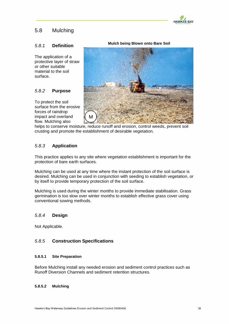
Mulch being Blown onto Bare Soil
Hawke‟s Bay Waterway Guidelines Erosion and Sediment Control 20090406 37
When Mulching, use unrotted small grain straw or hay applied at a density of 6,000 kg/ha such that the coverage is consistent or no bare soil is visible through the mulch layer. The mulch layer should remain until alternative stabilisation is achieved. Note that hay does not last long on the ground and remulching may be required. Ensure the material is free of any noxious plants. Mulching needs to be spread uniformly and secured to the soil surface. For smaller areas hand spreading of mulch material can be adequate. For larger sites, apply mulch mechanically to ensure even spread and appropriate application. Apply fertiliser and seed with Mulching as outlined in Table 5-4 of these Guidelines. Alternatives such as wood chips and chemical soil binders can be utilised where appropriate. Wood chips are suitable for areas that will not be closely mowed around such as ornamental plantings. They do not require the application of a tackifier and if readily available can be a relatively inexpensive mulch. They are slow to break down and normally require nitrogen application to prevent nutrient deficiency in plants. Do not use woodchips around watercourses or in areas where water can pond. To avoid water contamination, any alternative to straw mulch must be approved by the Hawke‟s Bay Regional Council. A wide range of synthetic mulching compounds are available to stabilise and protect the soil surface. These include emulsions, acrylimides and dispersions of vinyl compounds. They do not insulate the soil or retain moisture when used alone and therefore do little to aid seed establishment. They are also easily damaged by traffic, decompose relatively quickly and can be quite expensive in comparison to organic mulches. Rovings, another alternative, are fibres that are teased out from spools of yarn by compressed air and woven onto the surface of the land. They are then stabilised with a tackifier, with seed sown beforehand. These alternatives may be acceptable in certain circumstances but should be discussed in detail with the Hawke‟s Bay Regional Council prior to their implementation.
5.8.5.3 Anchoring Mulch
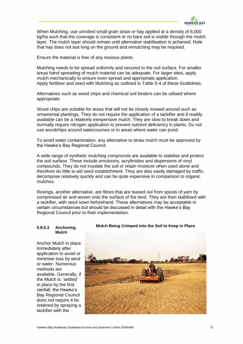
Anchor Mulch in place immediately after application to avoid or minimise loss by wind or water. Numerous methods are available. Generally, if the Mulch is `settled' in place by the first rainfall, the Hawke‟s Bay Regional Council does not require it be retained by spraying a tackifier with the
Mulch Being Crimped into the Soil to Keep in Place

Hawke‟s Bay Waterway Guidelines Erosion and Sediment Control 20090406 38
Mulch. However where wind blow is likely, particularly exposed sites or stockpiles, then tackifier is likely to be required. If mulch is being used during dry periods crimping using discs set at zero cut is a viable alternative. When using chemical tackifiers, take care to avoid adverse offsite effects of runoff, particularly around watercourses.
Hawke‟s Bay Waterway Guidelines Erosion and Sediment Control 20090406 39
5.9 Turfing
5.9.1 Definition
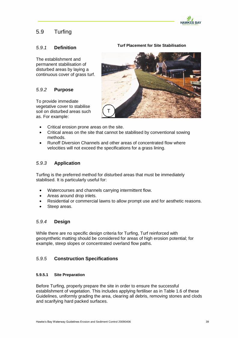
The establishment and permanent stabilisation of disturbed areas by laying a continuous cover of grass turf.
5.9.2 Purpose
To provide immediate vegetative cover to stabilise soil on disturbed areas such as. For example:
Critical erosion prone areas on the site.
Critical areas on the site that cannot be stabilised by conventional sowing methods.
Runoff Diversion Channels and other areas of concentrated flow where velocities will not exceed the specifications for a grass lining.
5.9.3 Application
Turfing is the preferred method for disturbed areas that must be immediately stabilised. It is particularly useful for:
Watercourses and channels carrying intermittent flow.
Areas around drop inlets.
Residential or commercial lawns to allow prompt use and for aesthetic reasons.
Steep areas.
5.9.4 Design
While there are no specific design criteria for Turfing, Turf reinforced with geosynthetic matting should be considered for areas of high erosion potential; for example, steep slopes or concentrated overland flow paths.
5.9.5 Construction Specifications
5.9.5.1 Site Preparation
Before Turfing, properly prepare the site in order to ensure the successful establishment of vegetation. This includes applying fertiliser as in Table 1.6 of these Guidelines, uniformly grading the area, clearing all debris, removing stones and clods and scarifying hard packed surfaces.
Turf Placement for Site Stabilisation
Hawke‟s Bay Waterway Guidelines Erosion and Sediment Control 20090406 40
5.9.5.2 Turf Installation
During periods of high temperatures, lightly irrigate soil immediately before laying turf. Lay the first row of turf in a straight line with subsequent rows placed parallel to and tightly wedged against each other. Stagger lateral joints in a brick-like pattern. Do not stretch or overlap turf and make sure all joints are butted tight in order to prevent voids, which can cause drying of the grass roots. On sloping areas or channels where erosion may be a problem, lay turf downslope with the ends of the turf material overlapped such that the upslope turf overlaps the downslope turf by at least 100 mm. It may be necessary to secure the turf with pegs or staples. Ensure the turf at the top of the slope is appropriately trenched in to prevent runoff moving underneath it. As Turfing is completed in one area, roll or tamp the entire area to ensure solid contact of the grass roots with the soil surface. After rolling, immediately water the Turf until the underside of the new turf and soil surface below the turf are thoroughly wet.
5.9.6 Maintenance
Water daily during the first week of laying unless there is adequate rainfall.
Do not mow the area until the turf is firmly rooted.
Apply fertiliser regularly as in Table 1.6 of these Guidelines for ongoing successful establishment.
Hawke‟s Bay Waterway Guidelines Erosion and Sediment Control 20090406 41
5.10 Erosion control matting
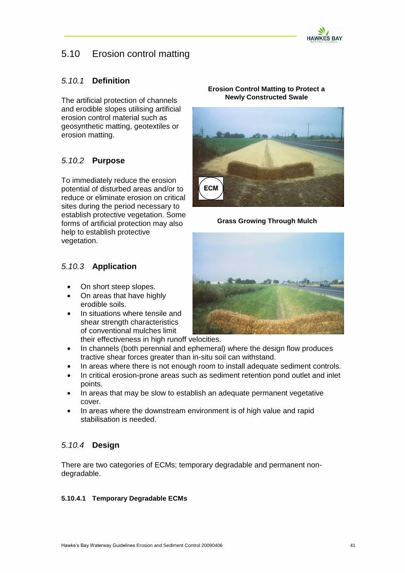
5.10.1 Definition
The artificial protection of channels and erodible slopes utilising artificial erosion control material such as geosynthetic matting, geotextiles or erosion matting.
5.10.2 Purpose
To immediately reduce the erosion potential of disturbed areas and/or to reduce or eliminate erosion on critical sites during the period necessary to establish protective vegetation. Some forms of artificial protection may also help to establish protective vegetation.
5.10.3 Application
On short steep slopes.
On areas that have highly erodible soils.
In situations where tensile and shear strength characteristics of conventional mulches limit their effectiveness in high runoff velocities.
In channels (both perennial and ephemeral) where the design flow produces tractive shear forces greater than in-situ soil can withstand.
In areas where there is not enough room to install adequate sediment controls.
In critical erosion-prone areas such as sediment retention pond outlet and inlet points.
In areas that may be slow to establish an adequate permanent vegetative cover.
In areas where the downstream environment is of high value and rapid stabilisation is needed.
5.10.4 Design
There are two categories of ECMs; temporary degradable and permanent non-degradable.
5.10.4.1 Temporary Degradable ECMs
Grass Growing Through Mulch
Erosion Control Matting to Protect a
Newly Constructed Swale

Hawke‟s Bay Waterway Guidelines Erosion and Sediment Control 20090406 42
These are used to prevent loss of seedbed and to promote vegetation establishment where vegetation alone will be sufficient for site protection once established. Common temporary ECMs are erosion control blankets, open weave meshes/matting and organic erosion control netting (fibre mats factory-bonded to synthetic netting).
5.10.4.2 Permanent Non-Degradable ECMs
These are used to extend the erosion control limits of vegetation, soil, rock or other materials. Common permanent ECMs are three-dimensional erosion control and revegetation mats, geocellular confinement systems, reno mattresses and gabions. The selection of an appropriate ECMs is a complex balancing of the relative importance of the following requirements:
Endurance: durability, degree of resistance to deformation over time and ultraviolet radiation and to chemicals (natural or as pollutants).
Physical: thickness, weight, specific gravity and degree of light penetration. Generally a thicker heavier material will provide better protection.
Hydraulic: ability of the system to resist tractive shear strength and protect against channel erosion, erosion of underlying soils or slope erosion from rainfall impact.
Mechanical: deformation and strength behaviour. Tensile strength and elongation, stiffness (how well it will conform to the subgrade) and how well it will resist tractive shear forces.
When a geotextile is to be used for temporary channel or spillway protection, consider combining a high strength, low permeability cloth over a soft pliable needle punch cloth pinned to ensure the cloth is in contact with the entire soil surface. Trench and pin all flow entry points such that the upslope geotextile edge overlaps the downslope geotextile mat. Toe in the upslope end of the downslope mat. In high risk areas such as spillways and diversions, pin geotextiles down on a 0.5 m grid or in accordance with the manufacturers' specifications, whichever provides the greatest number of contact points. There is a large number of products available for all situations and depending on the degree of protection needed, a product or combination of products will be available to suit the situation. It is vital that the product utilised is designed for the intended use and installed and maintained according to its specifications. Decision analysis techniques ranking the various ECMs available should be used based on the following categories.
Sediment yield (generally ranked highest)
Stability under flow
Vegetation enhancement
Durability
Cost When installing ECMs within a channel, it is important that the design velocity of the product is considered and again that the product chosen is appropriate for the use. Many products provide for the combination of a revegetation technique and an artificial erosion control measure. Again, design specifications need to be closely followed in all cases. For example when installing a topsoil reinforcing matrix a finely
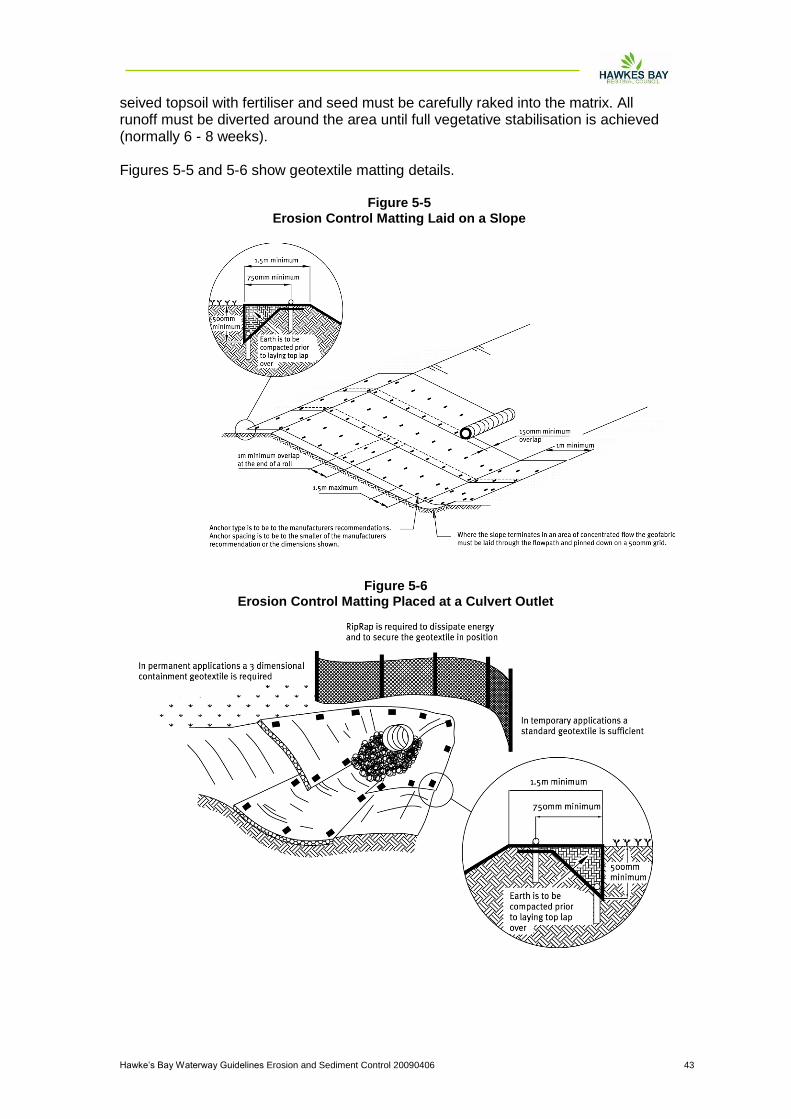
Hawke‟s Bay Waterway Guidelines Erosion and Sediment Control 20090406 43
seived topsoil with fertiliser and seed must be carefully raked into the matrix. All runoff must be diverted around the area until full vegetative stabilisation is achieved (normally 6 - 8 weeks). Figures 5-5 and 5-6 show geotextile matting details.
Figure 5-5
Erosion Control Matting Laid on a Slope
Figure 5-6
Erosion Control Matting Placed at a Culvert Outlet

Hawke‟s Bay Waterway Guidelines Erosion and Sediment Control 20090406 44
5.10.5 Maintenance
Inspect after every rainfall and undertake any maintenance immediately.

Hawke‟s Bay Waterway Guidelines Erosion and Sediment Control 20090406 45
5.11 Stabilised construction entrance
5.11.1 Definition
A stabilised pad of aggregate on a woven geotextile base located at any point where traffic will be entering or leaving a construction site.
5.11.2 Purpose
To prevent site access points from becoming sediment sources and to help minimise dust generation and disturbance of areas adjacent to the road frontage by giving a defined entry/exit point.
5.11.3 Application
Use a Stabilised Construction Entrance at all points of construction site ingress and egress with a construction plan limiting traffic to these entrances only. They are particularly useful on small construction sites but can be utilised for all projects.
5.11.4 Design
Clear the entrance and exit area of all vegetation, roots and other unsuitable material and properly grade it.
Lay woven geotextile; pin down edges and overlap joins.
Provide drainage to carry runoff from the Stabilised Construction Entrance to a sediment control measure.
Place aggregate to the specifications in Table 5-5 and smooth it.
Table 5-5
Aggregate Size 100 - 150 mm washed aggregate
Thickness 150 mm or 1.5 x aggregate size
Length 10 m minimum
Width 4 m minimum
Stabilised Construction Entrance Showing
Geotextile Fabric Underneath
Completed Stabilised Construction Entrance
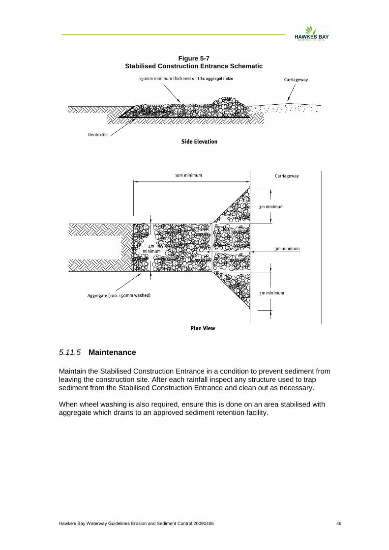
Hawke‟s Bay Waterway Guidelines Erosion and Sediment Control 20090406 46
5.11.5 Maintenance
Maintain the Stabilised Construction Entrance in a condition to prevent sediment from leaving the construction site. After each rainfall inspect any structure used to trap sediment from the Stabilised Construction Entrance and clean out as necessary. When wheel washing is also required, ensure this is done on an area stabilised with aggregate which drains to an approved sediment retention facility.
Figure 5-7
Stabilised Construction Entrance Schematic

Hawke‟s Bay Waterway Guidelines Erosion and Sediment Control 20090406 47
5.12 Pipe or Flume drop structure
5.12.1 Definition
A temporary pipe structure or constructed flume placed from the top of a slope to the bottom.
5.12.2 Purpose
A Pipe Drop Structure or a Flume is installed to convey surface runoff down the face of unstabilised slopes in order to minimise erosion on the slope face.
5.12.3 Application
Pipe Drop Structures or Flumes are used in conjunction with Runoff Diversion Channels. The Runoff Diversion Channels direct surface runoff to the Pipe Drop Structure or Flume which conveys concentrated flow down the face of a slope. If other forms of Pipe Drop Structures or Flumes are being considered, Hawke‟s Bay Regional Council approval of those structures will be necessary on a case by case basis.
5.12.4 Design
Construct all Pipe Drop Structures or Flumes of watertight materials.
Extend the Pipe Drop Structure or Flume beyond the toe of the slope and adequately protect the outlet from erosion using riprap over a geotextile apron.
Use of the design criteria in Table 5-6 for Pipe Drop Structure, is shown in Figure 5-8.
Table 5-6
Pipe Diameter (mm) Maximum Catchment Area (ha)
150 0.05
300 0.2
450 0.6
500 1.0
600 1.0
Ensure that at the Pipe Drop Structure or Flume inlet, the height of the Runoff Diversion Channel is at least twice the pipe diameter or height of Flume as measured from the invert.
Slope Drain Flume
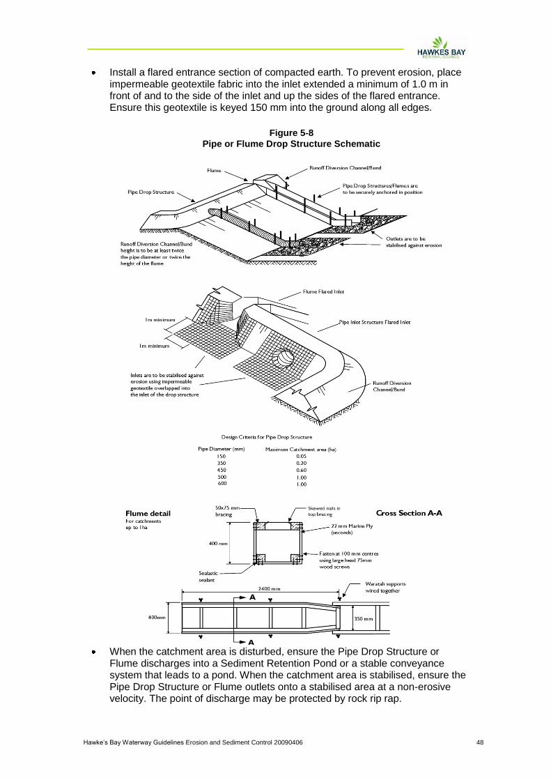
Hawke‟s Bay Waterway Guidelines Erosion and Sediment Control 20090406 48
Install a flared entrance section of compacted earth. To prevent erosion, place impermeable geotextile fabric into the inlet extended a minimum of 1.0 m in front of and to the side of the inlet and up the sides of the flared entrance. Ensure this geotextile is keyed 150 mm into the ground along all edges.
When the catchment area is disturbed, ensure the Pipe Drop Structure or Flume discharges into a Sediment Retention Pond or a stable conveyance system that leads to a pond. When the catchment area is stabilised, ensure the Pipe Drop Structure or Flume outlets onto a stabilised area at a non-erosive velocity. The point of discharge may be protected by rock rip rap.
Figure 5-8
Pipe or Flume Drop Structure Schematic
Hawke‟s Bay Waterway Guidelines Erosion and Sediment Control 20090406 49
Ensure the Pipe Drop Structure or Flume has a minimum slope of 3%.
5.12.5 Construction Specifications for Pipe Drop Structures
A common cause of failure of Pipe Drop Structures is water saturating the soil and seeping along the pipe where it connects to the Runoff Diversion Channel. Backfill properly around and under the pipe with stable material in order to achieve firm contact between the pipe and the soil at all points to eliminate this type of failure. Pipe material used for the Pipe Drop Structure can consist of rigid pipe material or flexible pipe as required. If flexible pipe material is utilised, it is vital that the material be pinned to the slope in the required position.
Place Pipe Drop Structures on undisturbed soil or well-compacted fill at locations as detailed within the Erosion and Sediment Control Plan for the site.
Immediately stabilise all disturbed areas following construction.
Secure the Pipe Drop Structure to the slope at least every 4 m. Use no less than two anchors equally spaced along the length of the pipe.
Ensure all pipe connections are watertight.
5.12.6 Construction Specifications for Flumes
A common failure of Flumes is outflanking of the Flume entrance or scouring of the invert to the Flume. This can be prevented by waterproofing the entrance to the Flume by trenching in an appropriate impervious geotextile or plastic liner so that all flows are channelled directly into the flume. Alternatively a piped entrance can be installed.
Flumes can be constructed from materials such as corrugated steel, construction ply, sawn timber or halved plastic piping.
Construct the Flume to ensure there are no leaks. For wooden or plywood Flumes or Flumes where leakage is likely, extend an impervious liner down the full length of the Flume structure.
For slopes greater than 30%, a Flume can be constructed from a standard 1.2 m x 2.4 m x 22mm plywood sheet. This will be adequate for a catchment of up to one ha. Specific design is required for larger catchments.
Fasten the Flume to the slope using waratahs or wooden stakes placed in pairs down the slope at 1 to 4 m spacings, depending on the Flume material used. Fasten the Flume to the waratahs or stakes using wire or steel strapping.
Place Flumes on undisturbed soil or well compacted fill at locations as detailed in the site's Erosion and Sediment Control Plan.
5.12.7 Maintenance
Inspect the Pipe Drop Structure/Flume periodically and after each rain event. Immediately carry out any maintenance required.
Keep the inlet open at all times.

Hawke‟s Bay Waterway Guidelines Erosion and Sediment Control 20090406 50
5.13 Level spreader
5.13.1 Definition
A non-erosive outlet for concentrated runoff constructed todisperse flows uniformly across a slope.
5.13.2 Purpose
To convert concentrated flow to sheet flow and release it uniformly over a stabilised area to prevent erosion. The Cleanwater Level Spreader provides a relatively low cost option which can release concentrated flow where site conditions are suitable. Particular care is needed to ensure the Cleanwater Level Spreader outlet lip is completely level and is in stable, undisturbed soil or is well armoured. Any depressions in the Cleanwater Level Spreader lip will reconcentrate flows, resulting in further erosion.
5.13.3 Application
Where sediment-free storm runoff can be released in a sheet flow over a stabilised slope without causing erosion.
Where sediment-laden overland flow can be released in sheet flow across the inlet to a Sediment Retention Pond.
Where the area below the Cleanwater Level Spreader lip is uniform with the slope of 10% or less and/or is stable for the anticipated flow conditions.
Where the runoff water will not re-concentrate after release.
Where there will be no traffic over the Cleanwater Level Spreader.
5.13.4 Design
Determine the capacity of the Cleanwater Level Spreader by estimating peak flow from the 20 year storm.
Where possible, choose a site for the Cleanwater Level Spreader that has a natural contour that will allow for the rapid spreading of flows, for example, at the end of a knoll or ridge.
Select the appropriate length, width and depth of the spreader from Table 5-7 below.
Table 5-7
Design Flow (m
3/sec)
Inlet Width (m) Depth (mm) End Width (m) Length (m)
0 - 0.3 3 150 1 3
0.3 - 0.6 5 180 1 7
0.6 - 0.9 7 220 1 10
Construct a 6 m long transition section in the Runoff Diversion Channel leading up to the Cleanwater Level Spreader so the width of the Runoff Diversion Channel will smoothly meet the width of the Cleanwater Level Spreader to
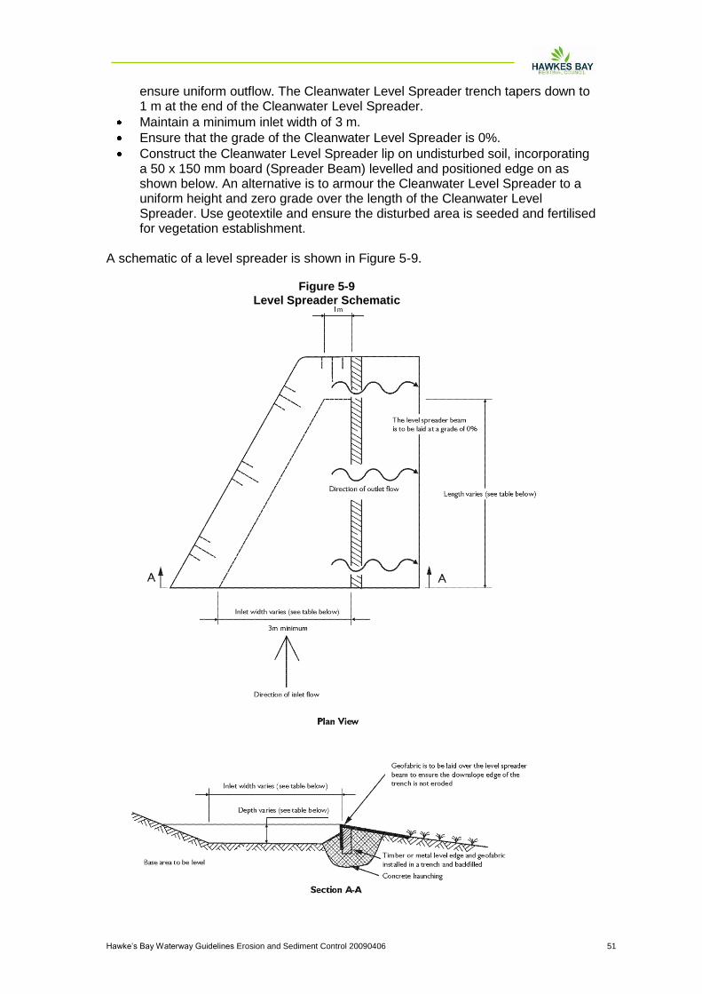
Hawke‟s Bay Waterway Guidelines Erosion and Sediment Control 20090406 51
ensure uniform outflow. The Cleanwater Level Spreader trench tapers down to 1 m at the end of the Cleanwater Level Spreader.
Maintain a minimum inlet width of 3 m.
Ensure that the grade of the Cleanwater Level Spreader is 0%.
Construct the Cleanwater Level Spreader lip on undisturbed soil, incorporating a 50 x 150 mm board (Spreader Beam) levelled and positioned edge on as shown below. An alternative is to armour the Cleanwater Level Spreader to a uniform height and zero grade over the length of the Cleanwater Level Spreader. Use geotextile and ensure the disturbed area is seeded and fertilised for vegetation establishment.
A schematic of a level spreader is shown in Figure 5-9.
Figure 5-9
Level Spreader Schematic

Hawke‟s Bay Waterway Guidelines Erosion and Sediment Control 20090406 52
5.13.5 Maintenance
Inspect Cleanwater Level Spreaders after every rainfall until vegetation is established and promptly undertake any necessary repairs. Ensure vegetation is kept in a healthy and vigorous condition.
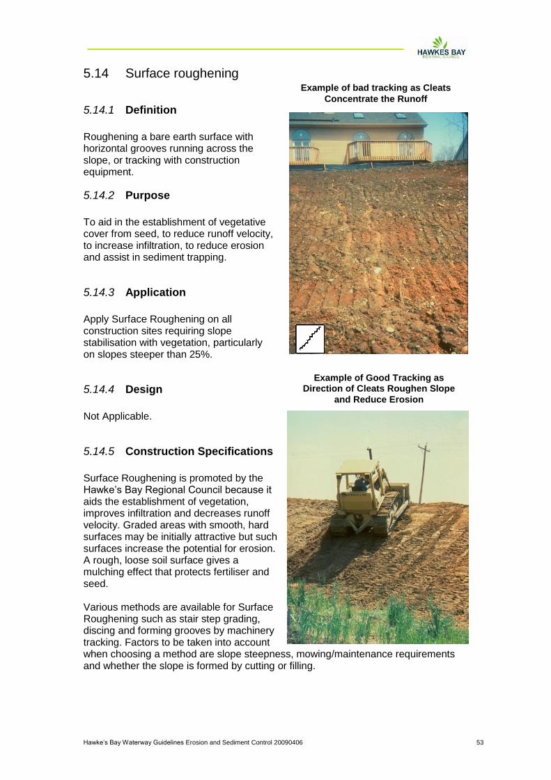
Hawke‟s Bay Waterway Guidelines Erosion and Sediment Control 20090406 53
5.14 Surface roughening
5.14.1 Definition
Roughening a bare earth surface with horizontal grooves running across the slope, or tracking with construction equipment.
5.14.2 Purpose
To aid in the establishment of vegetative cover from seed, to reduce runoff velocity, to increase infiltration, to reduce erosion and assist in sediment trapping.
5.14.3 Application
Apply Surface Roughening on all construction sites requiring slope stabilisation with vegetation, particularly on slopes steeper than 25%.
5.14.4 Design
Not Applicable.
5.14.5 Construction Specifications
Surface Roughening is promoted by the Hawke‟s Bay Regional Council because it aids the establishment of vegetation, improves infiltration and decreases runoff velocity. Graded areas with smooth, hard surfaces may be initially attractive but such surfaces increase the potential for erosion. A rough, loose soil surface gives a mulching effect that protects fertiliser and seed. Various methods are available for Surface Roughening such as stair step grading, discing and forming grooves by machinery tracking. Factors to be taken into account when choosing a method are slope steepness, mowing/maintenance requirements and whether the slope is formed by cutting or filling.
Example of bad tracking as Cleats
Concentrate the Runoff
Example of Good Tracking as Direction of Cleats Roughen Slope
and Reduce Erosion
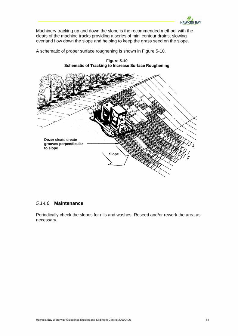
Hawke‟s Bay Waterway Guidelines Erosion and Sediment Control 20090406 54
Machinery tracking up and down the slope is the recommended method, with the cleats of the machine tracks providing a series of mini contour drains, slowing overland flow down the slope and helping to keep the grass seed on the slope. A schematic of proper surface roughening is shown in Figure 5-10.
5.14.6 Maintenance
Periodically check the slopes for rills and washes. Reseed and/or rework the area as necessary.
Figure 5-10
Schematic of Tracking to Increase Surface Roughening
Slope
Dozer cleats create grooves perpendicular
to slope
Hawke‟s Bay Waterway Guidelines Erosion and Sediment Control 20090406 55
6 Sediment Control Practices Erosion and sediment control are comprises of two different strategies:
Erosion control to limit the generation of sediment having transport potential, and
Sediment control, which removes sediment from stormwater runoff prior to the runoff entering receiving systems.
This section of the Guidelines provides information on capture of suspended sediments prior to exiting a construction site. Practice specifications are provided for the following:
Sediment retention ponds,
Flocculation
Silt fence,
Super silt fence,
Straw bale barrier,
Stormwater inlet protection,
Decanting earth and topsoil bunds, and
Sump, sediment pit
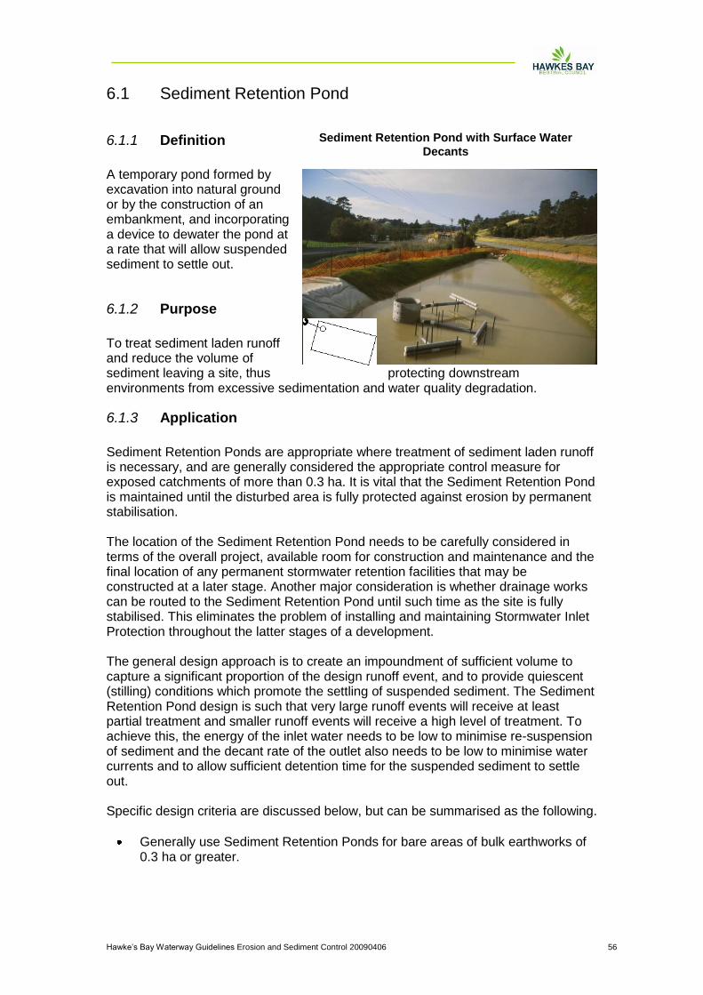
Hawke‟s Bay Waterway Guidelines Erosion and Sediment Control 20090406 56
6.1 Sediment Retention Pond
6.1.1 Definition
A temporary pond formed by excavation into natural ground or by the construction of an embankment, and incorporating a device to dewater the pond at a rate that will allow suspended sediment to settle out.
6.1.2 Purpose
To treat sediment laden runoff and reduce the volume of sediment leaving a site, thus protecting downstream environments from excessive sedimentation and water quality degradation.
6.1.3 Application
Sediment Retention Ponds are appropriate where treatment of sediment laden runoff is necessary, and are generally considered the appropriate control measure for exposed catchments of more than 0.3 ha. It is vital that the Sediment Retention Pond is maintained until the disturbed area is fully protected against erosion by permanent stabilisation. The location of the Sediment Retention Pond needs to be carefully considered in terms of the overall project, available room for construction and maintenance and the final location of any permanent stormwater retention facilities that may be constructed at a later stage. Another major consideration is whether drainage works can be routed to the Sediment Retention Pond until such time as the site is fully stabilised. This eliminates the problem of installing and maintaining Stormwater Inlet Protection throughout the latter stages of a development. The general design approach is to create an impoundment of sufficient volume to capture a significant proportion of the design runoff event, and to provide quiescent (stilling) conditions which promote the settling of suspended sediment. The Sediment Retention Pond design is such that very large runoff events will receive at least partial treatment and smaller runoff events will receive a high level of treatment. To achieve this, the energy of the inlet water needs to be low to minimise re-suspension of sediment and the decant rate of the outlet also needs to be low to minimise water currents and to allow sufficient detention time for the suspended sediment to settle out. Specific design criteria are discussed below, but can be summarised as the following.
Generally use Sediment Retention Ponds for bare areas of bulk earthworks of 0.3 ha or greater.
Sediment Retention Pond with Surface Water
Decants

Hawke‟s Bay Waterway Guidelines Erosion and Sediment Control 20090406 57
Restrict catchment areas to less than 5.0 ha per Sediment Retention Pond. This limits the length of overland flowpaths and reduces maintenance problems.
Locate Sediment Retention Ponds so as to provide a convenient collection point for sediment laden flows from the catchment area. This will require strategic use of cut-offs, Runoff Diversion Channels and Contour Drains.
Locate Sediment Retention Ponds to allow access for removing sediment from the pond.
Wherever possible, locate Sediment Retention Ponds to allow the spillway to discharge over undisturbed, well vegetated ground.
Keep the Sediment Retention Pond life to less than two years. If a longer term is required then further measures to ensure stability and effectiveness are likely to be needed.
Do not locate Sediment Retention Ponds within watercourses.
Embankment and spillway stability are generally the weak point in Sediment Retention Pond construction. Correct compaction particularly around emergency spillways, discharge pipes and antiseep collars, will keep the system robust.
A schematic of a sediment retention pond is shown in Figure 6-1.
Figure 6-1
Schematic of a Sediment Retention Pond
Hawke‟s Bay Waterway Guidelines Erosion and Sediment Control 20090406 58
6.1.4 Design - Size of the Pond
Calculate the volume of the Sediment Retention Pond using the depth measured from the base of the Sediment Retention Pond to the top of the outlet riser. The following design criteria apply.
On earthwork sites with slopes less than 10% and less than 200m in length, construct a Sediment Retention Pond with a minimum volume of 2% of the contributing catchment (200m3 for each ha of contributing catchment).
On sites with slopes greater than 10% and/or 200 m in length, construct Sediment Retention Ponds with a minimum volume of 3% of the contributing catchment (300m3 capacity for each ha of contributing catchment).
The slope angle is determined by that slope immediately above the Sediment Retention Pond or by the average slope angle over the contributing catchment, whichever is the greater.
For sand soils (less than 8% clay and less than 40% silt) or well structured volcanic loams the size of the Sediment Retention Pond may be calculated using the following formula _
o Pond Surface Area (square metres) = 1.5 x Peak Inflow Rate (litres per second),
o calculate the inflow rates using the 5% AEP rainfall event using Council accepted hydrologic procedures. Ensure the Sediment Retention Pond has a minimum depth of 1.0m,
o alternatively, construct Sediment Retention Ponds with a minimum volume of 150m3/ha of the contributing catchment for sand and 200m3 /ha for volcanic soil.
o As there many areas of the Hawke‟s Bay Region with loess or silty clay soils, which have a high silt content but are subject to erosion, sediment retention ponds should have a minimum volume of 180 m3/ha of the contributing catchment area.
On sites that are particularly steep or have sensitive downstream environments, a greater Sediment Retention Pond volume may be required.
Clean out Sediment Retention Ponds when the volume of sediment accumulated within them reaches 20% of the design volume.
Clearly show the Sediment Retention Pond dimensions necessary to obtain the required volume, as detailed above, on the site's Erosion and Sediment Control Plan(s).
6.1.5 Design - Dead Storage (Permanent Storage)
Dead storage is the component of impoundment volume that does not decant and remains in the Sediment Retention Pond. It is important for dissipating the energy of inflows.
Ensure dead storage is 30% of the total Sediment Retention Pond storage by positioning the lowest decant 0.4 - 0.8m above the invert of the Sediment Retention Pond.
The approved decant design detailed in these Guidelines allows the lower decant arm to be raised as sediment deposition increases, thereby maintaining the percentage volume of dead storage.
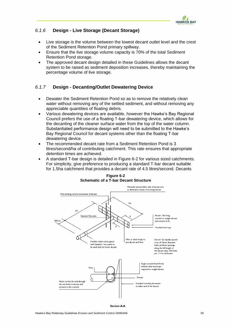
Hawke‟s Bay Waterway Guidelines Erosion and Sediment Control 20090406 59
6.1.6 Design - Live Storage (Decant Storage)
Live storage is the volume between the lowest decant outlet level and the crest of the Sediment Retention Pond primary spillway.
Ensure that the live storage volume capacity is 70% of the total Sediment Retention Pond storage.
The approved decant design detailed in these Guidelines allows the decant system to be raised as sediment deposition increases, thereby maintaining the percentage volume of live storage.
6.1.7 Design - Decanting/Outlet Dewatering Device
Dewater the Sediment Retention Pond so as to remove the relatively clean water without removing any of the settled sediment, and without removing any appreciable quantities of floating debris.
Various dewatering devices are available, however the Hawke‟s Bay Regional Council prefers the use of a floating T-bar dewatering device, which allows for the decanting of the cleaner surface water from the top of the water column. Substantiated performance design will need to be submitted to the Hawke‟s Bay Regional Council for decant systems other than the floating T-bar dewatering device.
The recommended decant rate from a Sediment Retention Pond is 3 litres/second/ha of contributing catchment. This rate ensures that appropriate detention times are achieved.
A standard T-bar design is detailed in Figure 6-2 for various sized catchments. For simplicity, give preference to producing a standard T-bar decant suitable for 1.5ha catchment that provides a decant rate of 4.5 litres/second. Decants
Figure 6-2
Schematic of a T-bar Decant Structure
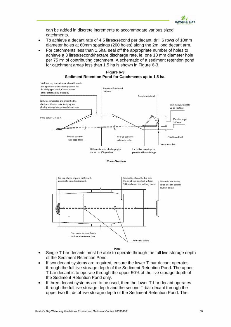
Hawke‟s Bay Waterway Guidelines Erosion and Sediment Control 20090406 60
can be added in discrete increments to accommodate various sized catchments.
To achieve a decant rate of 4.5 litres/second per decant, drill 6 rows of 10mm diameter holes at 60mm spacings (200 holes) along the 2m long decant arm.
For catchments less than 1.5ha, seal off the appropriate number of holes to achieve a 3 litres/second/hectare discharge rate, ie. one 10 mm diameter hole per 75 m2 of contributing catchment. A schematic of a sediment retention pond for catchment areas less than 1.5 ha is shown in Figure 6-3.
Single T-bar decants must be able to operate through the full live storage depth of the Sediment Retention Pond.
If two decant systems are required, ensure the lower T-bar decant operates through the full live storage depth of the Sediment Retention Pond. The upper T-bar decant is to operate through the upper 50% of the live storage depth of the Sediment Retention Pond only.
If three decant systems are to be used, then the lower T-bar decant operates through the full live storage depth and the second T-bar decant through the upper two thirds of live storage depth of the Sediment Retention Pond. The
Figure 6-3
Sediment Retention Pond for Catchments up to 1.5 ha.
Hawke‟s Bay Waterway Guidelines Erosion and Sediment Control 20090406 61
upper T-bar decant operates through the upper one third of live storage depth of the Sediment Retention Pond as detailed in Figure 2.1.4.
Ensure that the T-bar decant float is securely fastened with steel strapping directly on top of the decant arm and weight it to keep the decant arm submerged just below the surface through all stages of the decant cycle. This will also minimise the potential for blockage of the decant holes by floating debris. The most successful method found to date is to weight the decant arm by strapping a 1.8m long waratah between the float and the decant (approximately 4kg of weight).
Position the T-bar decant at the correct height by tying 5mm nylon cord through decant holes at either end of the decant arm and fastening it to waratahs driven in on either side of the decant.
Lay the discharge pipe at a 1 _ 2% gradient, compact the fill material around it using a machine compactor and incorporate anti-seep collars with the following criteria.
Install collars around the pipe to increase the seepage length along the pipe with a spacing of approximately 10m.
The vertical projection of each collar is 1.0m; ensure all anti seep collars and their connections are watertight.
Use a flexible thick rubber coupling to provide a connection between the decant arm and the primary spillway or discharge pipe. To provide sufficient flexibility (such as is required for the lower decant arm) install two couplings. Fasten the flexible coupling using strap clamps and glue.
Where a concrete riser decant system is utilised, ensure the lower decant connection is positioned on an angle upwards from the horizontal so as to split the operational angle that the decant works through. This will reduce the deformation force on the coupling used.
6.1.8 Design - Shape of the Pond
Ensure the length to width ratio of the Sediment Retention Pond is no less than 3:1 and no greater than 5:1. The length of the Sediment Retention Pond is measured as the distance between the inlet and the outlet (decant system). A 2:1 ratio may be used if the pond depth is no greater than 1.0m.
Maximise the distance between the inlet and the outlet (including the emergency spillway) to reduce the risk of short circuiting and to promote quiescent conditions. If this can not be achieved by correctly positioning the inlet and outlets, install baffles to achieve the appropriate length to width ratio design.
Ensure that the Sediment Retention Pond has a level invert as described below to promote the even and gradual dissipation of the heavier inflow water across the full area of the Sediment Retention Pond.
6.1.9 Design - Level Spreader
Incorporate a Level Spreader (Figure 6.1) into the inlet design to spread inflow velocities, thereby allowing rapid dissipation of inflow energies. Combine the Level Spreader with a well compacted and smoothed inlet batter (no steeper than a 3:1 gradient), stabilised over its entire area. The essential design feature is to ensure the Level Spreader is level, non-erodible and spans the full width of the Sediment Retention Pond.

Hawke‟s Bay Waterway Guidelines Erosion and Sediment Control 20090406 62
To ensure even inflows, install a trenched and pegged 200mm x 50mm timber weir or similar across the full width of the inlet. Concrete haunch the edges and the trench to prevent outflanking and leaking. This timber weir also serves to toe in the geotextile protection which will be required.
Position the top of the Level Spreader 100 - 200 mm above the invert of the emergency spillway.
The shape of the Level Spreader will vary with the direction and volume of the inlet diversion, but the entrance to the Level Spreader must be widened and flared to promote even flow.
6.1.10 Design - Baffles
Incorporate baffles in the Sediment Retention Pond design where the recommended pond shape cannot be achieved. Extend baffles the full depth of the Sediment Retention Pond and place them to maximise dissipation of flow energy.
Generally, baffles are in the form of a wing to direct inflows away from the outlet and maximise the stilling zone. A series of compartments within the pond can be used to achieve this, although care must be taken to avoid creating in-pond currents and resuspension of light particulates.
Baffles may be constructed from various materials ranging from solid shutter boards to braced geotextile curtains.
6.1.11 Design - Forebay
Incorporate a forebay with a depth of 1m and a width of 2m. The forebay is be the full length of the Level Spreader. The forebay should be cleaned out after rainfall.
6.1.12 Design - Depth of Pond
Sediment Retention Pond depths may be 1 - 2m deep, but no deeper than 2m. Deeper ponds are more likely to cause short circuiting problems during larger storm events and require specifically designed floating decant systems.
The decant design in these Guidelines operates through a maximum live storage range of 1.5m.
6.1.13 Design - Embankment
Pond Inlet Level Spreader

Hawke‟s Bay Waterway Guidelines Erosion and Sediment Control 20090406 63
Before building a Sediment Retention Pond, install sediment controls such as Silt Fences below the construction area and maintain them to a functional standard until the Sediment Retention Pond batters are fully stabilised.
Thoroughly compact the Sediment Retention Pond embankment, with material laid in 150 mm layers and compacted to engineering standards.
Where possible install the discharge pipes through the embankment as the embankment is being constructed.
Fully stabilise the external batter face, by vegetative or other means, immediately after construction.
Ensure all bare areas associated with the Sediment Retention Pond (including internal batters) are stabilised with vegetation if the Sediment Retention Pond is to remain in place over winter.
6.1.14 Design - Primary Spillway
For larger catchments (greater than 1.5ha) the Sediment Retention Pond requires a piped primary spillway (refer Figures 6-4 and 6-5).
Figure 6-4
Sediment Retention Pond for Catchments Between 1.5 - 3 ha.
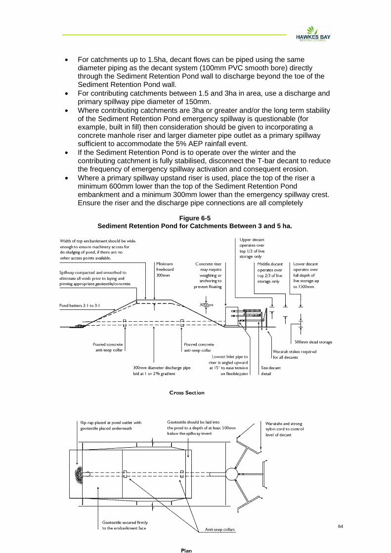
Hawke‟s Bay Waterway Guidelines Erosion and Sediment Control 20090406 64
For catchments up to 1.5ha, decant flows can be piped using the same diameter piping as the decant system (100mm PVC smooth bore) directly through the Sediment Retention Pond wall to discharge beyond the toe of the Sediment Retention Pond wall.
For contributing catchments between 1.5 and 3ha in area, use a discharge and primary spillway pipe diameter of 150mm.
Where contributing catchments are 3ha or greater and/or the long term stability of the Sediment Retention Pond emergency spillway is questionable (for example, built in fill) then consideration should be given to incorporating a concrete manhole riser and larger diameter pipe outlet as a primary spillway sufficient to accommodate the 5% AEP rainfall event.
If the Sediment Retention Pond is to operate over the winter and the contributing catchment is fully stabilised, disconnect the T-bar decant to reduce the frequency of emergency spillway activation and consequent erosion.
Where a primary spillway upstand riser is used, place the top of the riser a minimum 600mm lower than the top of the Sediment Retention Pond embankment and a minimum 300mm lower than the emergency spillway crest. Ensure the riser and the discharge pipe connections are all completely
Figure 6-5
Sediment Retention Pond for Catchments Between 3 and 5 ha.
Hawke‟s Bay Waterway Guidelines Erosion and Sediment Control 20090406 65
watertight.
Where possible, install the piping through the embankment as the embankment is being constructed.
6.1.15 Design - Emergency Spillway
An emergency spillway is essential for all Sediment Retention Ponds.
Emergency spillways must be capable of accommodating the 1% AEP event without eroding.
The outer emergency spillway crest and batter requires a very high standard of stabilisation with the fill material of the spillway batter well compacted.
Construct the emergency spillway as a stabilised trapezoidal cross section with a minimum bottom width of 6m.
When utilising geotextile for emergency spillway stabilisation purposes, the batter face must be smooth and all voids eliminated.
If geotextile is used, a soft neddle punch geotextile is laid first and then covered with a strong woven low permeability geotextile. Ensure the geotextile is pinned at 0.5m centres over the full area of the emergency spillway.
Where possible, construct emergency spillways in well vegetated, undisturbed ground (not fill) and discharge over long grass.
If the emergency spillway is constructed on bare soil, provide complete erosion protection by means such as grouted riprap, asphalt, erosion matting/geotextile or concrete.
Construct the emergency spillway with a minimum of 300mm freeboard height.
6.1.16 Construction Specifications
Construct a fabric silt fence across the downslope end of the proposed works.
Clear areas under proposed fills of topsoil or other unsuitable material down to competent material. Large fill embankments may need to be keyed in.
Use only approved fill.
Place and compact fill in layers as per the engineer's specifications.
Do not place pervious materials such as sand or gravel within the fill material.
Construct fill embankments approximately 10% higher than the design height to allow for settlement of the material. Install appropriate pipe work and antiseep collars during the construction of the embankment and compact around these appropriately.
Install the emergency spillway.
Install and stabilise the Level Spreader.
Securely attach the decant system to the horizontal pipework. Make all connections watertight. Place any manhole riser on a firm foundation of impervious soil.
Do not place pervious material such as sand or scoria around the discharge pipe or the antiseep collars.
Install baffles if required.
Check Sediment Retention Pond freeboard for differential settlement and rectify as necessary.
Stabilise both internal and external batters with vegetation and the emergency spillway in accordance with the site's approved Erosion and Sediment Control Plan.
Hawke‟s Bay Waterway Guidelines Erosion and Sediment Control 20090406 66
6.1.17 Pond Maintenance and Disposal of Sediment
Clean out Sediment Retention Ponds before the volume of accumulated sediment reaches 20% of the total Sediment Retention Pond volume. To assist in gauging sediment loads, clearly mark the 20% volume height on the decant riser.
Clean out Sediment Retention Ponds prior to the end of the bulk earthwork season if the ponds are to remain in operation over the winter period.
Clean out Sediment Retention Ponds with high capacity sludge pumps, or with excavators (long reach excavators if needed) loading onto sealed tip trucks or to a secure area.
The Erosion and Sediment Control Plan should identify disposal locations for the sediment removed from the Sediment Retention Pond. Deposit the sediment in such a location so that it does not lead to a direct discharge to receiving environments. Stabilise all disposal sites as required and approved in the site's Erosion and Sediment Control Plan.
Inspect Sediment Retention Ponds every day and before every forecasted rainfall event. Inspect for correct operation after every runoff event. Immediately repair any damage to Sediment Retention Ponds caused by erosion or construction equipment.
6.1.18 Safety
Sediment Retention Ponds are attractive to children and can become safety hazards if not appropriately fenced and if safety rules are not followed. Low gradient pond batters provide an additional safety measure. Check the safety requirements of the City or District Council Authority and the Occupational Safety and Health branch of the Department of Labour.
6.1.19 Chemical Treatment
Some chemicals can be used successfully to promote flocculation (clumping together) of suspended solids in the Sediment Retention Pond to increase the particle mass and speed the rate of settling. Recent trials have identified a simple and effective chemical dosing system that does not require a power supply. This system uses poly aluminium chloride (PAC) and has been found to be particularly effective in settling fines such as fine silts and clays. Other chemicals may become available as more trial data is obtained. Chemical dosing systems are likely to be required where the design Sediment Retention Pond volume cannot be achieved because of site constraints and/or where a high level of treatment is required because of the sensitivity of the receiving environment. Chemical treatment is also more likely to be required where the clay component is high or where the cumulative effects of sediment discharge are significant. Chemical dosing system design is shown in the next Section.
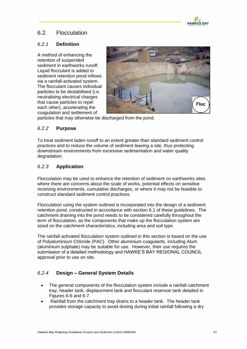
Hawke‟s Bay Waterway Guidelines Erosion and Sediment Control 20090406 67
6.2 Flocculation
6.2.1 Definition A method of enhancing the retention of suspended sediment in earthworks runoff. Liquid flocculant is added to sediment retention pond inflows via a rainfall-activated system. The flocculant causes individual particles to be destabilised (i.e. neutralising electrical charges that cause particles to repel each other), accelerating the coagulation and settlement of particles that may otherwise be discharged from the pond.
6.2.2 Purpose
To treat sediment laden runoff to an extent greater than standard sediment control practices and to reduce the volume of sediment leaving a site, thus protecting downstream environments from excessive sedimentation and water quality degradation.
6.2.3 Application
Flocculation may be used to enhance the retention of sediment on earthworks sites where there are concerns about the scale of works, potential effects on sensitive receiving environments, cumulative discharges, or where it may not be feasible to construct standard sediment control practices. Flocculation using the system outlined is incorporated into the design of a sediment retention pond, constructed in accordance with section 6.1 of these guidelines. The catchment draining into the pond needs to be considered carefully throughout the term of flocculation, as the components that make up the flocculation system are sized on the catchment characteristics, including area and soil type. The rainfall activated flocculation system outlined in this section is based on the use of Polyaluminium Chloride (PAC). Other aluminium coagulants, including Alum (aluminium sulphate) may be suitable for use. However, their use requires the submission of a detailed methodology and HAWKE‟S BAY REGIONAL COUNCIL approval prior to use on site.
6.2.4 Design – General System Details
The general components of the flocculation system include a rainfall catchment tray, header tank, displacement tank and flocculant reservoir tank detailed in Figures 6-6 and 6-7.
Rainfall from the catchment tray drains to a header tank. The header tank provides storage capacity to avoid dosing during initial rainfall following a dry
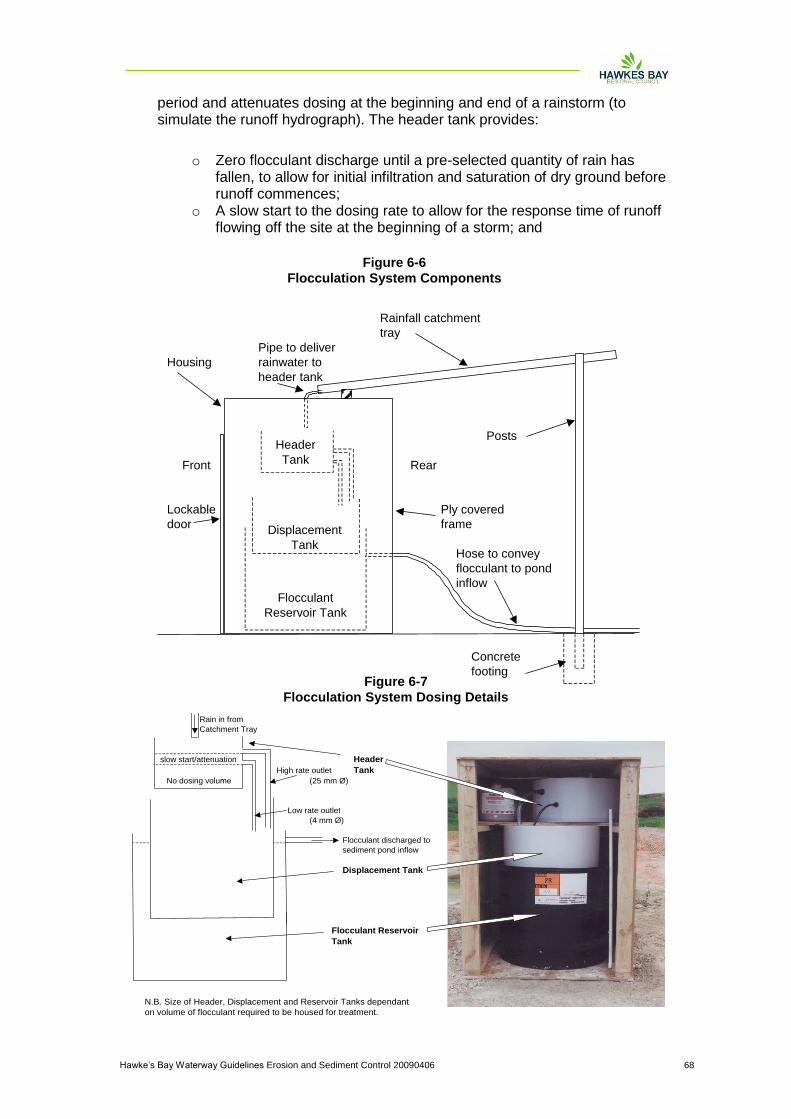
Hawke‟s Bay Waterway Guidelines Erosion and Sediment Control 20090406 68
period and attenuates dosing at the beginning and end of a rainstorm (to simulate the runoff hydrograph). The header tank provides:
o Zero flocculant discharge until a pre-selected quantity of rain has fallen, to allow for initial infiltration and saturation of dry ground before runoff commences;
o A slow start to the dosing rate to allow for the response time of runoff flowing off the site at the beginning of a storm; and
Rainfall catchment
tray
Pipe to deliver
Housing rainwater to
header tank
Posts
Front Rear
Lockable Ply covered
door frame
Hose to convey
flocculant to pond
inflow
Concrete
footing
Header
Tank
Displacement
Tank
Flocculant
Reservoir Tank
Figure 6-6
Flocculation System Components
Rain in from
Catchment Tray
slow start/attenuation Header
High rate outlet Tank
No dosing volume (25 mm Ø)
Low rate outlet
(4 mm Ø)
Flocculant discharged to
sediment pond inflow
Displacement Tank
Flocculant Reservoir
Tank
N.B. Size of Header, Displacement and Reservoir Tanks dependant
on volume of flocculant required to be housed for treatment.
Figure 6-7
Flocculation System Dosing Details
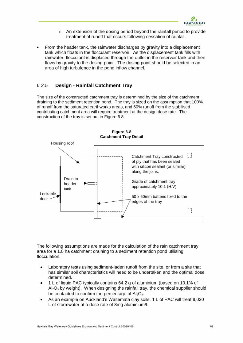
Hawke‟s Bay Waterway Guidelines Erosion and Sediment Control 20090406 69
o An extension of the dosing period beyond the rainfall period to provide treatment of runoff that occurs following cessation of rainfall.
From the header tank, the rainwater discharges by gravity into a displacement tank which floats in the flocculant reservoir. As the displacement tank fills with rainwater, flocculant is displaced through the outlet in the reservoir tank and then flows by gravity to the dosing point. The dosing point should be selected in an area of high turbulence in the pond inflow channel.
6.2.5 Design - Rainfall Catchment Tray
The size of the constructed catchment tray is determined by the size of the catchment draining to the sediment retention pond. The tray is sized on the assumption that 100% of runoff from the saturated earthworks areas, and 60% runoff from the stabilised contributing catchment area will require treatment at the design dose rate. The construction of the tray is set out in Figure 6.8.
The following assumptions are made for the calculation of the rain catchment tray area for a 1.0 ha catchment draining to a sediment retention pond utilising flocculation.
Laboratory tests using sediment-laden runoff from the site, or from a site that has similar soil characteristics will need to be undertaken and the optimal dose determined.
1 L of liquid PAC typically contains 64.2 g of aluminium (based on 10.1% of Al2O3 by weight). When designing the rainfall tray, the chemical supplier should
be contacted to confirm the percentage of Al2O3.
As an example on Auckland‟s Waitemata clay soils, 1 L of PAC will treat 8,020 L of stormwater at a dose rate of 8mg aluminium/L.
Housing roof
Lockable
door
Drain to
header
tank
Catchment Tray constructed
of ply that has been sealed
with silicon sealant (or similar)
along the joins.
Grade of catchment tray
approximately 10:1 (H:V)
50 x 50mm battens fixed to the
edges of the tray
Figure 6-8
Catchment Tray Detail

Hawke‟s Bay Waterway Guidelines Erosion and Sediment Control 20090406 70
For the purposes of sizing the tray, a 50mm storm event is considered. The runoff volume to be treated from 50mm of rainfall is 500 m3 for a 1 ha catchment.
The volume of PAC required to treat 500 m3 of runoff is 62.3 L.
The density of PAC is 1.2, therefore 74.8 L of rainwater needs to be collected to displace 62.3 L of PAC.
To collect 74.8 L of rainwater from a 50mm rainfall event requires an area of
1.5 m2. A larger catchment tray will be required for a larger contributing
catchment area.
Tests need to be done on Hawke’s Bay Region soils to determine optimal dosing rates on disturbed lands.
Table 6.1 outlines the catchment tray areas required for different PAC dose rates.
Table 6-1
Rainfall Catchment Tray area Required for Different PAC Dose Rates
Aluminium Dose Required
(mg/L)
Catchment Tray
Area/Hectare (m )*
2 0.375
4 0.75
6 1.125
8 1.5
10 1.875
12 2.25
Note: * Stabilised catchment calculated at 60% of area given.
PAC with 10.1% of Al2O3 by weight
6.2.6 Design - Header Tank Size
The zero (flocculant) discharge rainfall volume can be adjusted manually for site
characteristics by adding or removing water from the header tank.
Low rate and high rate outlets are to be installed. The low rate outlet consists of a 4mm internal diameter hose. The high rate outlet needs to have sufficient capacity to convey the maximum predicted flow from short-term rainfall, up to 40mm/hour. A pipe with an internal diameter of 25 mm is suggested, although systems treating large catchments may require larger pipes.
The slow start/attenuation characteristics can be regulated for site characteristics by providing more than one low rate outlet and at different levels from the header tank.
The standard header tank design provides for up to 10mm of rainfall before dosing commences. This requires provision of a delayed start volume below the low rate outlet of the header tank of 10 L/m
2 of rainfall catchment tray (for a 1.5m
2
catchment tray, the invert of the low rate outlet will be at the height reached by 15 L of water within the header tank). The high rate outlet invert should be positioned at that point reached by half the 50mm storm event (for a 1.5m
2 catchment tray, the
invert of the high rate outlet will be at the height reached by 37.5 L of water within the header tank).
The header tank should have sufficient capacity to contain rainfall without over topping. 50 mm of freeboard above the top of the high rate outlet pipe provides this capacity.
Hawke‟s Bay Waterway Guidelines Erosion and Sediment Control 20090406 71
6.2.7 Design - Displacement Tank Size
The displacement tank needs to be a neat fit inside the flocculant reservoir tank.
The minimum displacement tank capacity is the equivalent of the 50% AEP 24 hour storm event. For example, this is approximately 86 mm of rain for the Napier area, giving a volume of 150 L from a constructed catchment of 1.5 m2 for a 1.0 ha catchment. Therefore, a 200 L tank would be suitable in the Napier area for a 1.0 ha catchment.
6.2.8 Design - Flocculant Reservoir Tank
The flocculant reservoir tank needs to be only slightly larger than the displacement tank. However, the larger the reservoir and displacement tanks are, the less servicing that is required.
The flocculant reservoir tank requires sufficient capacity to provide for the dosing of runoff from the 50%AEP 24-hour rainfall event.
An outlet hose needs to be installed in the side of the tank to drain the flocculant to the pond inlet channel.
C o m m e n t s
Soils in the Hawke’s Bay region often have acidic runoff. The pH of soils should be tested prior to and during earthworks as the exposure of different soil horizons may alter the runoff pH. Dosing with aluminium-based flocculant shall cease where the pH drops below 5.5. Below this level, the toxicity of the aluminium fraction of the flocculant increases, potentially placing at risk receiving environment organisms.
Flocculation systems require a high degree of vigilance and monitoring and maintenance. Spills of the flocculant and discharge to receiving environments have the potential for significant adverse effects. The housing should be locked to discourage vandalism, and any flocculant storage bunded to protect the site from spillages or leaks.
It is important that an individual on site is charged with the responsibility of overseeing the operations and maintenance of the flocculation system. Detailed monitoring and maintenance records should be kept detailing rainfall on site, the catchment area being served by the flocculation unit (area and degree of stabilisation), the volume of flocculant used, and any other relevant matters.
As an alternative to aluminium based flocculant, a flocculation system utilising a saturated saline brine has been employed on an earthworks site in the past.
Initial indications suggest this system was effective at promoting retention of suspended matter within a sediment retention pond. Such systems should be considered where a site discharges directly or via the stormwater system to a marine environment.
Laboratory testing using saline brine should be undertaken to assess the optimal dose rate (experience to date suggests a dosage rate equivalent of 0.25 – 0.5% sea water: pond influent (volume: volume) is effective at promoting settlement).
Hawke‟s Bay Waterway Guidelines Erosion and Sediment Control 20090406 72
Achieving a saline brine requires a high degree of mixing of raw salt and water, which may be achieved manually, or through the use of a large paint mixer and electric drill. A brineometer should to be used to determine the level of saturation. Laboratory tests have shown that raw, unwashed sea salt provides the most effective saline brine to promote flocculation.
The use of flocculation will lead to more frequent sediment retention pond maintenance. The sediment containing the flocculant is not considered to be toxic as the aluminium is bound up with the soil particles. It is common practice for the accumulated sediment to be dried on site and incorporated into fills. It should not be placed in a manner where runoff from this material can enter surface water directly.
6.2.9 Maintenance
The maintenance requirements of the flocculant system need assessing following every rainfall event, or during rainfall events if exceptionally heavy and/or prolonged rainfall occurs.
Prior to staff leaving the site unattended for weekends, the flocculation unit requires servicing by the responsible site staff member so that the maximum amount of runoff can be treated by the dosing system.
The following matters outline maintenance requirements for the flocculation system. It is noted that these systems may require some ongoing manipulation to suit the site characteristics and runoff.
6.2.9.1 Header Tank
The water level of the header tank is to be set to allow for certain rainfall before flocculant dosing starts.
When the site is dry, it is estimated that up to 10mm of rain may fall prior to runoff reaching the sediment retention pond. Therefore the header tank should remain empty in such conditions to allow for a delayed response.
In wet weather or if the site is generally wet, water may be added manually to the header tank to cut down the response time so that the system responds more rapidly after rain commences. If the system is to be operated over the winter period, then the system should also be set to no delay.
Adjusting the water level within the header tank is to prevent under or overdosing of the pond. Under-dosing may lead to higher levels of suspended sediment being discharged from the pond, while overdosing may cause a reduction in pH, raising the potential for aluminium within PAC to react forming toxic aluminium compounds (that are bioavailable to fresh and marine water organisms).
6.2.9.2 Refilling with Flocculant
When the volume of flocculant in the reservoir tank is reduced to the degree that there is insufficient to dose a major storm, the displacement tank needs emptying and the flocculant reservoir refilled.
Hawke‟s Bay Waterway Guidelines Erosion and Sediment Control 20090406 73
The displacement tank may either be emptied using a siphon, or baled out by hand. The flocculant reservoir may be filled using a drum pump, to pump from a 200 L drum.
6.2.9.3 Monitoring and Adjustment for Changing Site Conditions
Each new flocculant treatment system needs to be monitored carefully during the first few rainfall events to check that the system is effective, and to ensure that overdosing is not occurring.
If overdosing is suspected because the pond dead storage water is exceptionally clear, samples must be taken from the pond for pH and dissolved aluminium analysis. The dosing regime should be adjusted depending on the outcome of these results.
If overdosing occurs or it is clear that the quality of stormwater runoff is improving because of stabilisation of the site, the flocculant dose must be reduced by reducing the size of the catchment tray. This can be done by placing and sealing a board (batten) diagonally across the tray with a hole through the tray rim at the lower corner, so that water from the tray area above the batten discharges to waste.
The size of the rainfall catchment tray requires modification if earthworks alter the extent of the contributing catchment. Failure to do so will cause either under or over dosing of flows entering the sediment retention pond.
Other maintenance includes the removal of any debris such as leaves from the catchment tray to ensure that rainwater enters the header tank. The low and high rate hoses need to be checked regularly for blockages. In addition, all hose fittings need to be inspected regularly to identify any leakages.
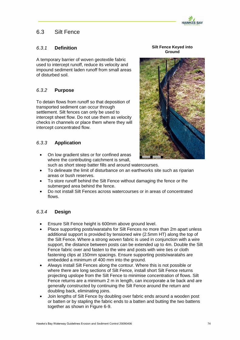
Hawke‟s Bay Waterway Guidelines Erosion and Sediment Control 20090406 74
6.3 Silt Fence
6.3.1 Definition
A temporary barrier of woven geotextile fabric used to intercept runoff, reduce its velocity and impound sediment laden runoff from small areas of disturbed soil.
6.3.2 Purpose
To detain flows from runoff so that deposition of transported sediment can occur through settlement. Silt fences can only be used to intercept sheet flow. Do not use them as velocity checks in channels or place them where they will intercept concentrated flow.
6.3.3 Application
On low gradient sites or for confined areas where the contributing catchment is small, such as short steep batter fills and around watercourses.
To delineate the limit of disturbance on an earthworks site such as riparian areas or bush reserves.
To store runoff behind the Silt Fence without damaging the fence or the submerged area behind the fence.
Do not install Silt Fences across watercourses or in areas of concentrated flows.
6.3.4 Design
Ensure Silt Fence height is 600mm above ground level.
Place supporting posts/waratahs for Silt Fences no more than 2m apart unless additional support is provided by tensioned wire (2.5mm HT) along the top of the Silt Fence. Where a strong woven fabric is used in conjunction with a wire support, the distance between posts can be extended up to 4m. Double the Silt Fence fabric over and fasten to the wire and posts with wire ties or cloth fastening clips at 150mm spacings. Ensure supporting posts/waratahs are embedded a minimum of 400 mm into the ground.
Always install Silt Fences along the contour. Where this is not possible or where there are long sections of Silt Fence, install short Silt Fence returns projecting upslope from the Silt Fence to minimise concentration of flows. Silt Fence returns are a minimum 2 m in length, can incorporate a tie back and are generally constructed by continuing the Silt Fence around the return and doubling back, eliminating joins.
Join lengths of Silt Fence by doubling over fabric ends around a wooden post or batten or by stapling the fabric ends to a batten and butting the two battens together as shown in Figure 6-9.
Silt Fence Keyed into
Ground

Hawke‟s Bay Waterway Guidelines Erosion and Sediment Control 20090406 75
Maximum slope lengths, spacing of returns and angles for Silt Fences are shown in Table 6-2.
Install Silt Fence wings at either end of the Silt Fence projecting upslope to a sufficient height to prevent outflanking.
Where impounded flow may overtop the Silt Fence, crossing natural depressions or low points, make provision for a riprap splash pad or other outlet protection device.
Use of Silt Fences in catchments of more than 0.5ha requires careful consideration of specific site measures, and other control measures maybe better, such as Super Silt Fence.
Where water may pond regularly behind the Silt Fence, provide extra support for the Silt Fence with tie backs from the Silt Fence to a central stable point on
Figure 6-9
Schematic of Silt Fence

Hawke‟s Bay Waterway Guidelines Erosion and Sediment Control 20090406 76
the upward side. Extra support can also be provided by stringing wire between support stakes and connecting the filter fabric to this wire.
The fabric cloth must meet the following requirements for Geotextile fabric:
o Tension Strength: 0.345 pa (minimum) o Tensile Modulus: 0.140 pa (minimum) o Apparent Opening Size 100 mm
Table 6-2
Silt Fence Design Criteria
Slope Steepness (%) Slope Length (m) Maximum
Spacing of Returns (m)
Silt Fence Length (m) Maximum
Flatter than 2% Unlimited N/A Unlimited
2 - 10 40 60 300
10 - 20 30 50 230
20 - 33 20 40 150
33 - 50 15 30 75
> 50 6 20 40
6.3.5 Construction Specifications
Use Silt Fence material appropriate to the site conditions and in accordance with the manufacturer's specifications.
Excavate a trench a minimum of 100mm wide and 200mm deep along the proposed line of the Silt Fence. Install the support posts on the downslope edge of the trench and Silt Fence fabric on the upslope side of the support posts to the full depth of the trench, then backfill the trench with compacted soil.
Use supporting posts of tanalised timber a minimum of 50mm square, or steel waratahs at least 1.5m in length.
Reinforce the top of the Silt Fence fabric with a support made of high tensile 2.5mm diameter galvanised wire. Tension the wire using permanent wire strainers attached to angled waratahs at the end of the Silt Fence.
Where ends of Silt Fence fabric come together, ensure they are overlapped, folded and stapled/screwed to prevent sediment bypass.
6.3.6 Maintenance
Inspect Silt Fences at least once a week and after each rainfall. Make any necessary repairs and remove sediment when bulges occur or when sediment accumulation reaches 50% of the fabric height.
Any areas of collapse, decomposition or ineffectiveness need to be immediately replaced.
Remove sediment deposits as necessary to continue to allow for adequate sediment storage and reduce pressure on the Silt Fence. Ensure that the sediment is removed to a secure area.
Do not remove Silt Fence materials and sediment deposition until the catchment area has been appropriately stabilised. Stabilise the area of the removed Silt Fence.

Hawke‟s Bay Waterway Guidelines Erosion and Sediment Control 20090406 77
6.4 Super silt fence
6.4.1 Definition
A temporary barrier of geotextile fabric over chain link fence that is used to intercept flows, reduce their velocity and impound sediment-laden runoff from small catchment areas.
6.4.2 Purpose
To reduce runoff velocity and allow the deposition of transported sediment to occur. A Super Silt Fence provides much more robust sediment control than a standard Silt Fence and allows up to four times the catchment area to be treated by an equivalent length of standard Silt Fence.
6.4.3 Application
Provides a barrier that can collect and hold debris and soil, preventing the material from entering critical areas, watercourses and streets.
Can be used where the installation of an Earth or Topsoil Bund would destroy sensitive areas such as bush and wetlands.
Should be placed as close to the contour as possible. No section of the fence should exceed a grade of 5% for a distance of more than 15m.
6.4.4 Design
When considering Super Silt Fence installation for larger catchments (greater than 0.5ha) as in Table 6-10, carefully consider the specific site conditions and other alternative control measures available. Base the length of the Super Silt Fence on the limits shown in Table 6-3. Limits imposed by ultraviolet light affect the stability of the fabric and will dictate the maximum period that the Super Silt Fence may be used. Where ends of the geotextile fabric come together, overlap, fold and staple the fabric ends to prevent sediment bypass.
Table 6-3 Super Silt Fence design Criteria
Slope (%) Slope Length (m) Maximum Length (m) Maximum
0 - 10 Unlimited Unlimited
10 - 20 60 450
20 - 33 30 300
Super Silt Fence at Toe of Slope that has
Recently been Vegetatively Stabilised

Hawke‟s Bay Waterway Guidelines Erosion and Sediment Control 20090406 78
33 - 50 30 150
> 50 15 75
6.4.5 Construction Specifications
Use a Silt Fence fabric that is appropriate to the site conditions and fits the manufacturer's specifications.
Excavate a trench 100mm wide by 200mm deep along the line of the Super Silt Fence.
Position the posts (No. 3 rounds, No. 2 half rounds or waratahs) at no greater than 3 m centres on the downslope side of the trench. While there is no need to set the posts in concrete, ensure the 1.8m long posts are driven to an appropriate depth (1m minimum).
Install tensioned galvanised wire (2.5 mmHT) at 400mm and again at 800mm above ground level using permanent wire strainers.
Secure chain link fence to the fence posts with wire ties or staples, ensuring the chain link fence goes to the base of the trench.
Figure 6-10
Super Silt Fence Schematic

Hawke‟s Bay Waterway Guidelines Erosion and Sediment Control 20090406 79
Fasten two layers of geotextile fabric securely to the Super Silt Fence with ties spaced every 60cm at the top and mid section of the Super Silt Fence.
Place the two layers of geotextile fabric to the base of the trench (a minimum of 300mm into the ground) and place compacted backfill back to the original ground level.
When two sections of geotextile fabric adjoin each other, ensure they are doubled over a minimum of 300mm, wrapped around a batten and fastened at 75mm spacings to prevent sediment bypass.
The geotextile fabric must meet the following requirements:
o Tension Strength 0.345 pa (minimum) o Tensile Modulus 0.140 pa (minimum) o Apparent Opening Size 100 - 500 mm
6.4.6 Maintenance
Inspect regularly and before and after storm events. Undertake maintenance as needed and remove silt buildups when bulges develop in the Super Silt Fence or when sediment deposition reaches 50% of the Super Silt Fence height.
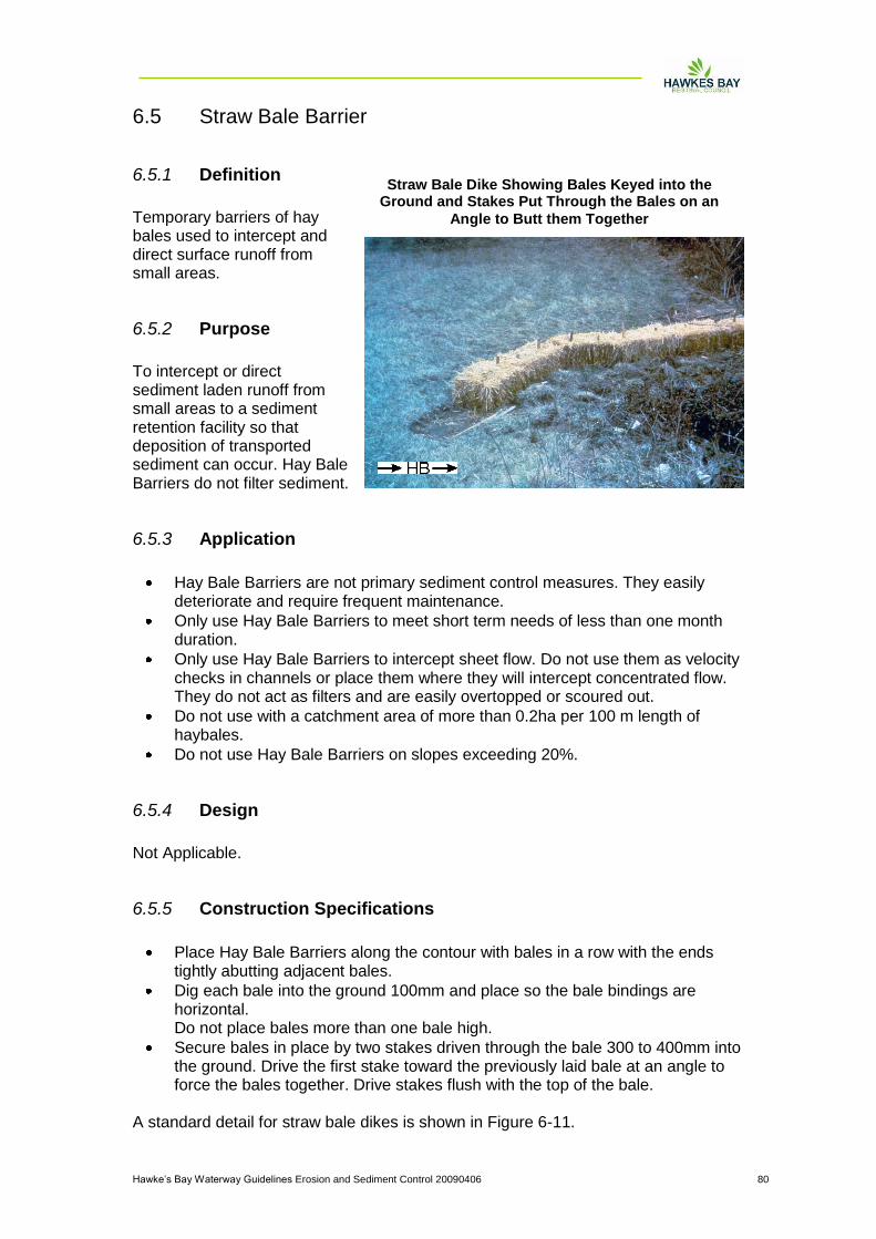
Hawke‟s Bay Waterway Guidelines Erosion and Sediment Control 20090406 80
6.5 Straw Bale Barrier
6.5.1 Definition
Temporary barriers of hay bales used to intercept and direct surface runoff from small areas.
6.5.2 Purpose
To intercept or direct sediment laden runoff from small areas to a sediment retention facility so that deposition of transported sediment can occur. Hay Bale Barriers do not filter sediment.
6.5.3 Application
Hay Bale Barriers are not primary sediment control measures. They easily deteriorate and require frequent maintenance.
Only use Hay Bale Barriers to meet short term needs of less than one month duration.
Only use Hay Bale Barriers to intercept sheet flow. Do not use them as velocity checks in channels or place them where they will intercept concentrated flow. They do not act as filters and are easily overtopped or scoured out.
Do not use with a catchment area of more than 0.2ha per 100 m length of haybales.
Do not use Hay Bale Barriers on slopes exceeding 20%.
6.5.4 Design
Not Applicable.
6.5.5 Construction Specifications
Place Hay Bale Barriers along the contour with bales in a row with the ends tightly abutting adjacent bales.
Dig each bale into the ground 100mm and place so the bale bindings are horizontal. Do not place bales more than one bale high.
Secure bales in place by two stakes driven through the bale 300 to 400mm into the ground. Drive the first stake toward the previously laid bale at an angle to force the bales together. Drive stakes flush with the top of the bale.
A standard detail for straw bale dikes is shown in Figure 6-11.
Straw Bale Dike Showing Bales Keyed into the Ground and Stakes Put Through the Bales on an
Angle to Butt them Together
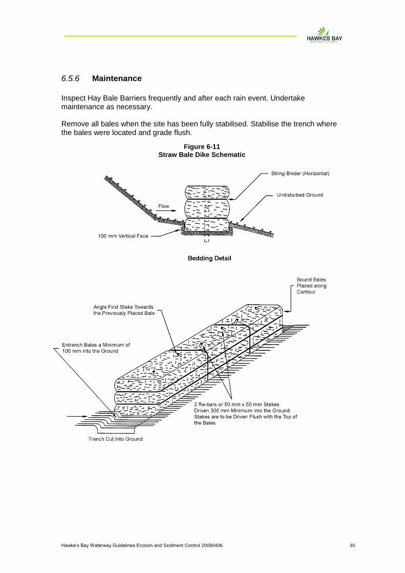
Hawke‟s Bay Waterway Guidelines Erosion and Sediment Control 20090406 81
6.5.6 Maintenance
Inspect Hay Bale Barriers frequently and after each rain event. Undertake maintenance as necessary. Remove all bales when the site has been fully stabilised. Stabilise the trench where the bales were located and grade flush.
Figure 6-11
Straw Bale Dike Schematic
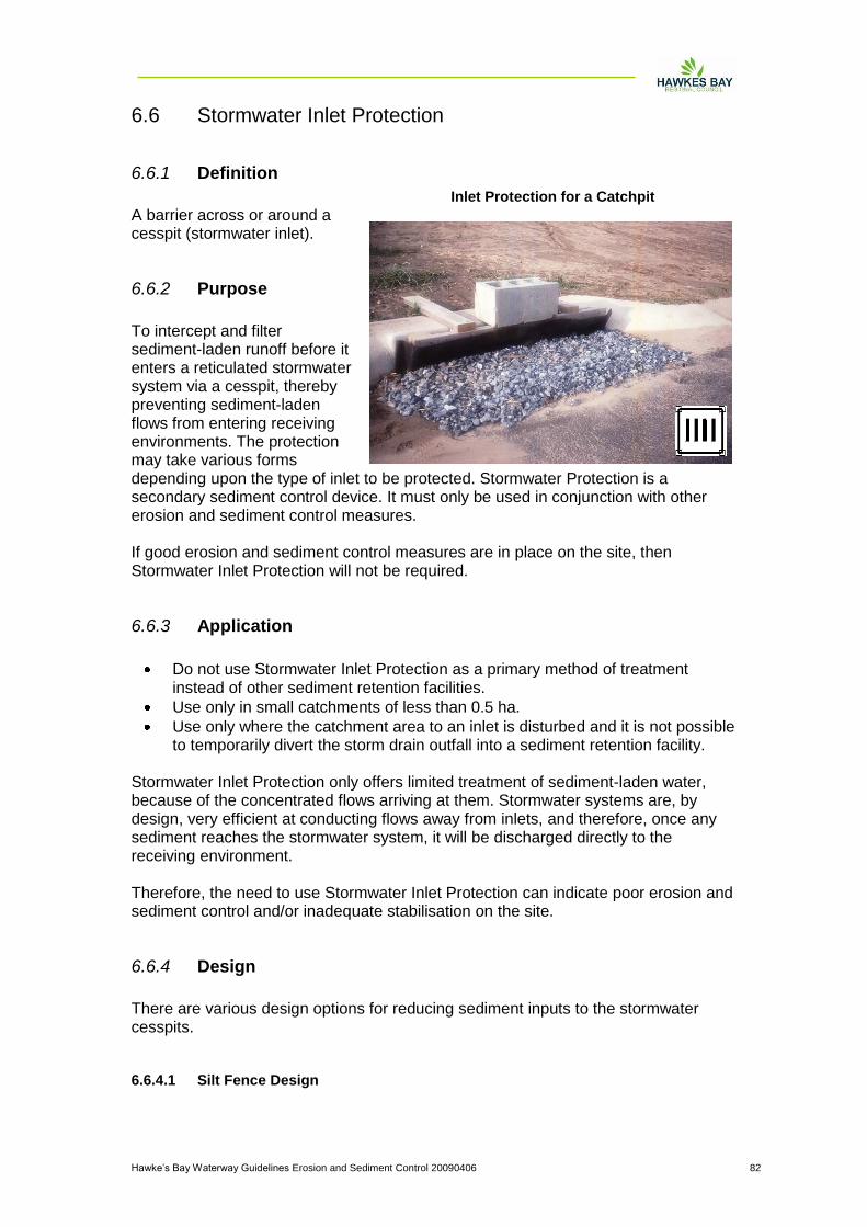
Hawke‟s Bay Waterway Guidelines Erosion and Sediment Control 20090406 82
6.6 Stormwater Inlet Protection
6.6.1 Definition
A barrier across or around a cesspit (stormwater inlet).
6.6.2 Purpose
To intercept and filter sediment-laden runoff before it enters a reticulated stormwater system via a cesspit, thereby preventing sediment-laden flows from entering receiving environments. The protection may take various forms depending upon the type of inlet to be protected. Stormwater Protection is a secondary sediment control device. It must only be used in conjunction with other erosion and sediment control measures. If good erosion and sediment control measures are in place on the site, then Stormwater Inlet Protection will not be required.
6.6.3 Application
Do not use Stormwater Inlet Protection as a primary method of treatment instead of other sediment retention facilities.
Use only in small catchments of less than 0.5 ha.
Use only where the catchment area to an inlet is disturbed and it is not possible to temporarily divert the storm drain outfall into a sediment retention facility.
Stormwater Inlet Protection only offers limited treatment of sediment-laden water, because of the concentrated flows arriving at them. Stormwater systems are, by design, very efficient at conducting flows away from inlets, and therefore, once any sediment reaches the stormwater system, it will be discharged directly to the receiving environment. Therefore, the need to use Stormwater Inlet Protection can indicate poor erosion and sediment control and/or inadequate stabilisation on the site.
6.6.4 Design
There are various design options for reducing sediment inputs to the stormwater cesspits.
6.6.4.1 Silt Fence Design
Inlet Protection for a Catchpit
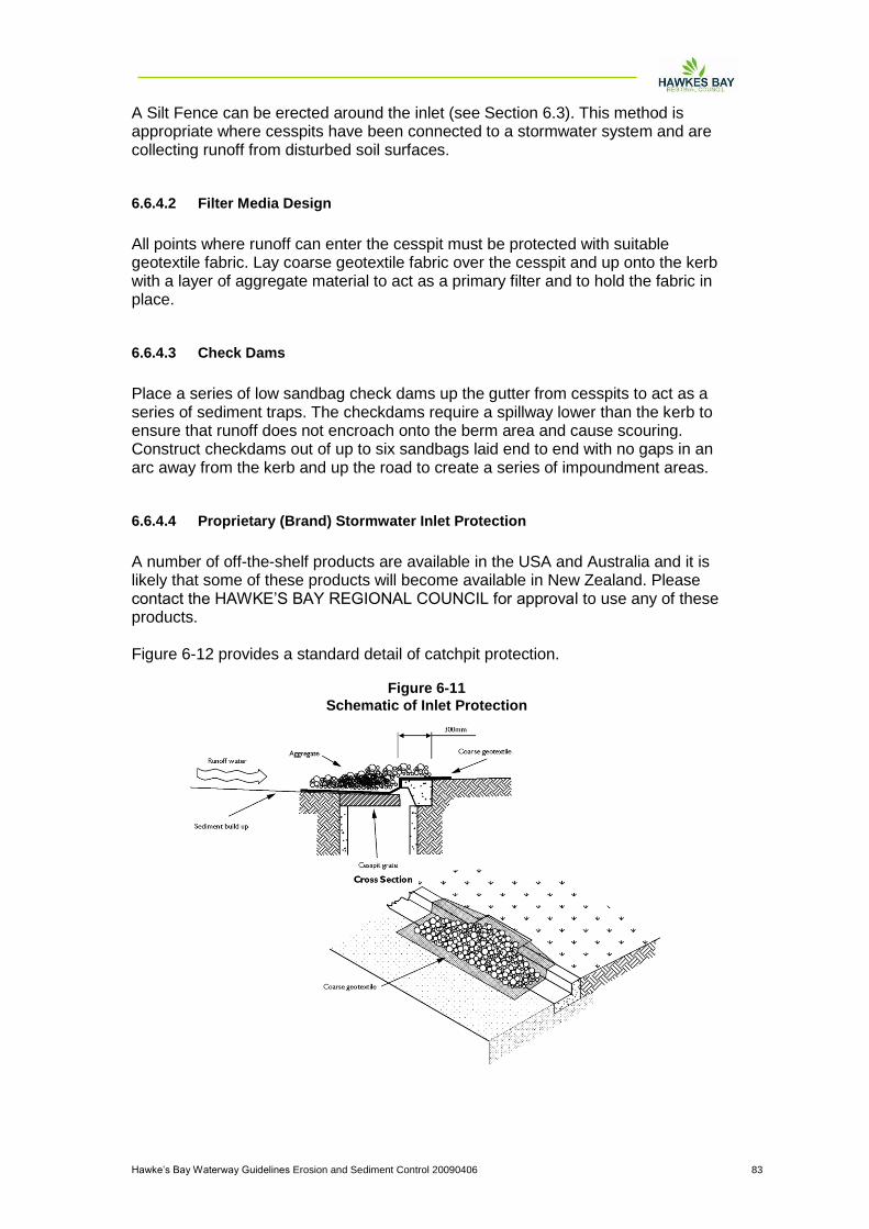
Hawke‟s Bay Waterway Guidelines Erosion and Sediment Control 20090406 83
A Silt Fence can be erected around the inlet (see Section 6.3). This method is appropriate where cesspits have been connected to a stormwater system and are collecting runoff from disturbed soil surfaces.
6.6.4.2 Filter Media Design
All points where runoff can enter the cesspit must be protected with suitable geotextile fabric. Lay coarse geotextile fabric over the cesspit and up onto the kerb with a layer of aggregate material to act as a primary filter and to hold the fabric in place.
6.6.4.3 Check Dams
Place a series of low sandbag check dams up the gutter from cesspits to act as a series of sediment traps. The checkdams require a spillway lower than the kerb to ensure that runoff does not encroach onto the berm area and cause scouring. Construct checkdams out of up to six sandbags laid end to end with no gaps in an arc away from the kerb and up the road to create a series of impoundment areas.
6.6.4.4 Proprietary (Brand) Stormwater Inlet Protection
A number of off-the-shelf products are available in the USA and Australia and it is likely that some of these products will become available in New Zealand. Please contact the HAWKE‟S BAY REGIONAL COUNCIL for approval to use any of these products. Figure 6-12 provides a standard detail of catchpit protection.
Figure 6-11
Schematic of Inlet Protection

Hawke‟s Bay Waterway Guidelines Erosion and Sediment Control 20090406 84
6.6.5 Maintenance
Maintenance requirements for cesspit protection measures are high because they clog easily. When clogging occurs, remove accumulated sediment and clean or replace the geotextile fabric and aggregate. Inspect all Stormwater Inlet Protection measures following any rainfall event and maintain as necessary to ensure they operate effectively. Stormwater Inlet Protection provides, at best, limited sediment retention. Do not use it as a primary method of sediment control. Use additional measures up-slope, such as topsoil bunds and cut-off drains, to minimise the volume of sediment reaching any stormwater inlets. Cesspits must at all times remain able to convey flow from the site to prevent large concentrated highly erosive flows from building up and causing washouts in secondary overland paths.
6.6.6 Construction Specifications
Construct Silt Fences for Stormwater Inlet Protection as outlined in Section 6.3 of these Guidelines.
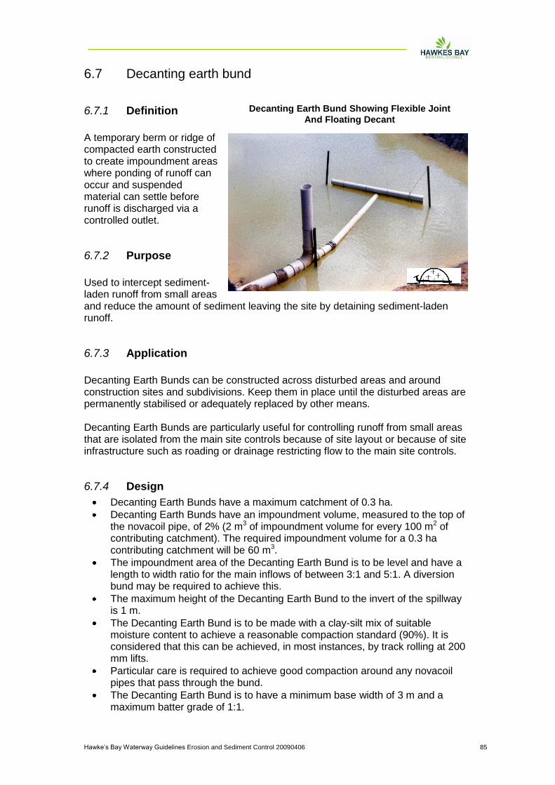
Hawke‟s Bay Waterway Guidelines Erosion and Sediment Control 20090406 85
6.7 Decanting earth bund
6.7.1 Definition
A temporary berm or ridge of compacted earth constructed to create impoundment areas where ponding of runoff can occur and suspended material can settle before runoff is discharged via a controlled outlet.
6.7.2 Purpose
Used to intercept sediment-laden runoff from small areas and reduce the amount of sediment leaving the site by detaining sediment-laden runoff.
6.7.3 Application
Decanting Earth Bunds can be constructed across disturbed areas and around construction sites and subdivisions. Keep them in place until the disturbed areas are permanently stabilised or adequately replaced by other means. Decanting Earth Bunds are particularly useful for controlling runoff from small areas that are isolated from the main site controls because of site layout or because of site infrastructure such as roading or drainage restricting flow to the main site controls.
6.7.4 Design
Decanting Earth Bunds have a maximum catchment of 0.3 ha.
Decanting Earth Bunds have an impoundment volume, measured to the top of the novacoil pipe, of 2% (2 m3 of impoundment volume for every 100 m2 of contributing catchment). The required impoundment volume for a 0.3 ha contributing catchment will be 60 m3.
The impoundment area of the Decanting Earth Bund is to be level and have a length to width ratio for the main inflows of between 3:1 and 5:1. A diversion bund may be required to achieve this.
The maximum height of the Decanting Earth Bund to the invert of the spillway is 1 m.
The Decanting Earth Bund is to be made with a clay-silt mix of suitable moisture content to achieve a reasonable compaction standard (90%). It is considered that this can be achieved, in most instances, by track rolling at 200 mm lifts.
Particular care is required to achieve good compaction around any novacoil pipes that pass through the bund.
The Decanting Earth Bund is to have a minimum base width of 3 m and a maximum batter grade of 1:1.
Decanting Earth Bund Showing Flexible Joint
And Floating Decant
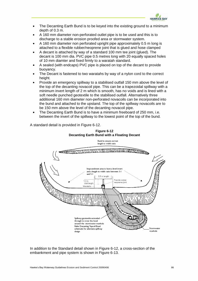
Hawke‟s Bay Waterway Guidelines Erosion and Sediment Control 20090406 86
The Decanting Earth Bund is to be keyed into the existing ground to a minimum depth of 0.3 m.
A 160 mm diameter non-perforated outlet pipe is to be used and this is to discharge to a stable erosion proofed area or stormwater system.
A 160 mm diameter non perforated upright pipe approximately 0.5 m long is attached to a flexible rubber/neoprene joint that is glued and hose clamped
A decant is attached by way of a standard 100 mm tee joint (glued). The decant is 100 mm dia. PVC pipe 0.5 metres long with 20 equally spaced holes of 10 mm diamter and fixed firmly to a waratah standard.
A sealed (with endcaps) PVC pipe is placed on top of the decant to provide buoyancy.
The Decant is fastened to two waratahs by way of a nylon cord to the correct height.
Provide an emergency spillway to a stabilised outfall 150 mm above the level of the top of the decanting novacoil pipe. This can be a trapezoidal spillway with a minimum invert length of 2 m which is smooth, has no voids and is lined with a soft needle punched geotextile to the stabilised outfall. Alternatively three additional 160 mm diameter non-perforated novacoils can be incorporated into the bund and attached to the upstand. The top of the spillway novacoils are to be 150 mm above the level of the decanting novacoil pipe.
The Decanting Earth Bund is to have a minimum freeboard of 250 mm, i.e. between the invert of the spillway to the lowest point of the top of the bund.
A standard detail is provided in Figure 6-12.
In addition to the Standard detail shown in Figure 6-12, a cross-section of the embankment and pipe system is shown in Figure 6-13.
Figure 6-12
Decanting Earth Bund with a Floating Decant

Hawke‟s Bay Waterway Guidelines Erosion and Sediment Control 20090406 87
6.7.5 Maintenance
Inspect and maintain Decanting Earth Bunds regularly and after each rainfall event to check for accumulated sediment which may cause overtopping. The decant upstand is likely to require tapping to drain impounded water. Check any discharge points for signs of scouring and install further armouring or other stabilisation if scouring is evident.
Figure 6-13
Cross-section of a Floating Decant
Hawke‟s Bay Waterway Guidelines Erosion and Sediment Control 20090406 88
6.8 Decanting topsoil bund
6.8.1 Definition
A temporary berm or ridge of compacted topsoil constructed to create impoundment areas where ponding of runoff can occur and suspended material can settle before runoff is discharged via a controlled outlet.
6.8.2 Purpose
Used to intercept sediment-laden runoff from small topsoiled areas and reduce the amount of sediment leaving the site by detaining sediment-laden runoff. Decanting Topsoil Bunds also provide a secure outfall for cleanwater flows from stabilised catchments.
6.8.3 Application
Decanting Topsoil Bunds are particularly useful for controlling runoff after topsoiling and grassing before vegetation becomes established. Decanting Topsoil Bunds can provide separation of stabilised areas from areas such as road berms which are to be worked when bulk earthworks are completed. Where works are occurring within the berm area, compact the topsoil as a bund adjacent and parallel to the berm. This will act as an impoundment area and if a controlled outfall is provided overland flow can be kept away from the construction area.
6.8.4 Design
The design of a decanting topsoil bund is the same as the decanting earth bund other than the use of topsoil as the bund material other than using topsoil as the embankment material. The topsoil decanting bund is for the situation where grading has been completed, topsoil established but vegetation has not yet established.
6.8.5 Maintenance
Inspect and maintain Decanting Topsoil Bunds regularly and after each rainfall event to check for accumulated sediment which may cause overtopping. Check any discharge points for signs of scouring and install further armouring or other stabilisation if scouring is evident.
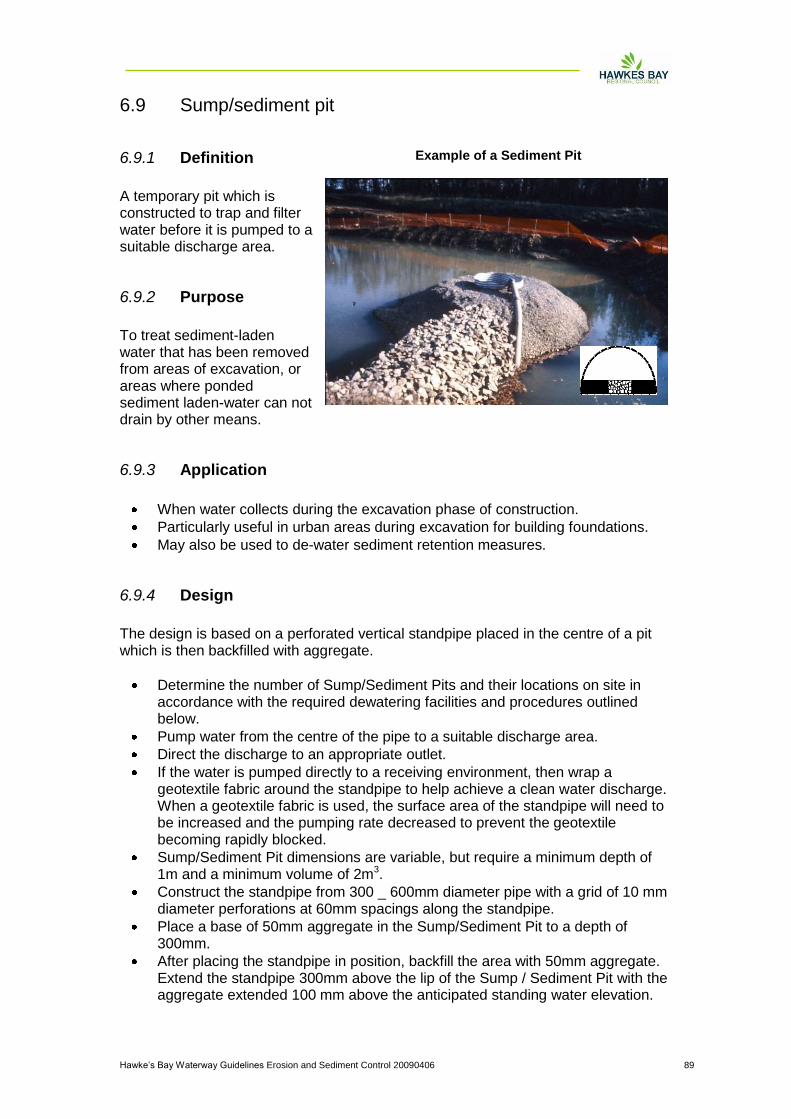
Hawke‟s Bay Waterway Guidelines Erosion and Sediment Control 20090406 89
6.9 Sump/sediment pit
6.9.1 Definition
A temporary pit which is constructed to trap and filter water before it is pumped to a suitable discharge area.
6.9.2 Purpose
To treat sediment-laden water that has been removed from areas of excavation, or areas where ponded sediment laden-water can not drain by other means.
6.9.3 Application
When water collects during the excavation phase of construction.
Particularly useful in urban areas during excavation for building foundations.
May also be used to de-water sediment retention measures.
6.9.4 Design
The design is based on a perforated vertical standpipe placed in the centre of a pit which is then backfilled with aggregate.
Determine the number of Sump/Sediment Pits and their locations on site in accordance with the required dewatering facilities and procedures outlined below.
Pump water from the centre of the pipe to a suitable discharge area.
Direct the discharge to an appropriate outlet.
If the water is pumped directly to a receiving environment, then wrap a geotextile fabric around the standpipe to help achieve a clean water discharge. When a geotextile fabric is used, the surface area of the standpipe will need to be increased and the pumping rate decreased to prevent the geotextile becoming rapidly blocked.
Sump/Sediment Pit dimensions are variable, but require a minimum depth of 1m and a minimum volume of 2m3.
Construct the standpipe from 300 _ 600mm diameter pipe with a grid of 10 mm diameter perforations at 60mm spacings along the standpipe.
Place a base of 50mm aggregate in the Sump/Sediment Pit to a depth of 300mm.
After placing the standpipe in position, backfill the area with 50mm aggregate. Extend the standpipe 300mm above the lip of the Sump / Sediment Pit with the aggregate extended 100 mm above the anticipated standing water elevation.
Example of a Sediment Pit

Hawke‟s Bay Waterway Guidelines Erosion and Sediment Control 20090406 90
Figure 6-14 shows a schematic of a sump/sediment pit.
6.9.5 Maintenance
Undertake ongoing checks throughout the use of the Sump/Sediment Pit to ensure effective operation. For isolated areas where dewatering must occur to facilitate progress, other methods may be appropriate. These alternatives include the following.
Pumping accumulated sediment-laden water to a sediment retention pond.
Constructing a Silt Fence and pumping water to behind the Silt Fence to be retained for treatment. Do not let water to be treated enter the Silt Fence as a concentrated flow or outflank the Silt Fence.
Discharge accumulated sediment laden water to land where soakage may occur. Ensure that this untreated sediment-laden runoff cannot enter to a stormwater system or any watercourse.
Figure 6-14
Schematic of a Sump/Sediment Pit

Hawke‟s Bay Waterway Guidelines Erosion and Sediment Control 20090406 91
7 Quarries Quarries are potentially a major source of sediment. They are often exposed for long periods of time and the area of bare earth can be considerable. Their continuous operation means that site conditions continually change. Careful planning is required to ensure that the operations are carried out with minimal environmental impact. It is the responsibility of the quarry operator to minimise the adverse environmental effects of the operation. This section of these Guidelines is designed to help quarry operators address soil and water problems which may arise as a result of quarry operations. It should be read in conjunction with Sections 5 and 6 of these Guidelines, which detail specific erosion and sediment control practices. Quarries are required to produce management plans covering the various aspects of their operation. These Guidelines will help in the production of such plans. The following specific issues associated with quarry operations are discussed below.
Road access
Stormwater
Overburden disposal
Stockpile areas
Rehabilitation of worked out areas
Riparian protection areas
Maintenance schedule for erosion and sediment control treatment structures
7.1 Road Access Many quarries in the Hawke‟s Bay Region are serviced by metal roads, used in all weather conditions. Vehicle movements during rain can generate a lot of sediment. These roads, however, are not always within the designated quarry area and therefore, are not covered by the Quarry Management Plan. Careful consideration needs to be given to managing roads and traffic. In cases such as these, erosion and sediment control measures need to be installed along roads as outlined in Sections 5 and 6 of these Guidelines. Where possible, incorporate road access into the Quarry Management Plan, ensuring all measures necessary are put in place to protect receiving environments.
7.2 Stormwater
7.2.1 Clean Runoff
As far as it is possible, divert clean water flow away from working and bare areas to prevent them from becoming contaminated by sediment. This aids in reducing the volume of contaminated runoff needing to be controlled and treated. Runoff Diversion Channels around the working site, as outlined in Section 5.1, are the simplest way to deal with the clean runoff.

Hawke‟s Bay Waterway Guidelines Erosion and Sediment Control 20090406 92
7.2.2 Contaminated Runoff
Any runoff from bare areas will collect sediment and become contaminated. This contaminated runoff, which includes runoff from aggregate wash processes, must be contained and treated in an appropriate manner before being discharged to natural watercourses. The Quarry Management Plan must detail the methods for containment and treatment of all contaminated runoff. Particular attention should be paid to sensitive areas such as permanent watercourses, watercourse crossings and steeply sloping bare areas. Design all structures for the 5% AEP rainfall event.
7.3 Overburden Disposal Methods of overburden disposal vary for each quarry operation. Overburden removal and disposal sites can be a major source of erosion and sediment discharges from quarries, particularly if the disposal site is not properly located and managed. The Quarry Management Plan for the site should give a reasonable indication of the following.
The timing and extent of overburden stripping, which will be related to an expected volume and area of extraction.
The methods to be employed for disposing the overburden.
Ongoing management of disposal sites, including provision for regular disposal of material trapped in sediment retention ponds.
If overburden disposal is dealt with in isolation from the Quarry Management Plan, consideration must be given to the following points.
Selection of disposal site (why the site was chosen).
Stability of the site and subsequent overburden fill (batter slopes, safety factors, benching, underlying material, drainage).
Erosion and sediment control measures.
Rehabilitation of disposal site (revegetation, contouring).
7.4 Stockpile Areas Stockpile areas include those used for stockpiling both raw or finished quarry products prior to further processing or final despatch. These areas can be a major source of contaminated runoff if not properly controlled. Position stockpiles well away from any watercourses and runoff flow paths.
7.5 Rehabilitation of Worked Out Areas Planning for rehabilitation must be an integral part of all quarry operations. A properly planned and implemented rehabilitation programme will reduce the need for expensive ongoing erosion control, and control and treatment of contaminated runoff. The aim of site rehabilitation, whether temporary or permanent, is to maintain the site in a condition such that erosion and contaminated runoff are limited to an acceptable level. The prime areas for consideration are:
Establishing suitable final ground contours;
Establishing a suitable environment for vegetation growth;
Revegetating the site with suitable vegetation cover.
Hawke‟s Bay Waterway Guidelines Erosion and Sediment Control 20090406 93
7.6 Riparian Protection Areas Riparian protection areas rely on vegetation to provide a buffer between the quarry operations and a water body such as a watercourse or wetland. These margins act as a physical barrier to keep machines away from sensitive areas as well as serving as a last resort sediment trap for diffuse runoff and/or unforeseen discharges. Do not, however, rely on riparian protection areas as a primary sediment control mechanism.
7.7 Maintenance Schedule for Erosion and Sediment Control or Treatment Structures
Because quarry operations continue over a very long time frame, it is important to develop a maintenance schedule for any control/treatment structures that are put in place. Money spent on designing and constructing control/treatment structures will be wasted if these structures are not adequately maintained. Properly maintained structures will provide optimum performance at all times, thereby minimising the adverse environmental effects of the quarry operation. Conversely, poorly maintained structures are likely to result in unsatisfactory environmental protection despite being initially well designed and constructed. Develop a maintenance schedule for the site that clearly indicates what is to be done in terms of visual inspections and maintenance works. Undertake routine maintenance works when they will cause the least possible detrimental environmental effects (either directly or indirectly). For example, do not clean sediment retention ponds during or immediately after rainfall events. To ensure that the operation of the pond is not affected at these critical times, maintenance should be done prior to events. It is also particularly important that all control/treatment structures are inspected after significant rainfall events, or during prolonged rainfall, in addition to any regular scheduled inspections. In the maintenance schedule include a procedure for immediately repairing and remedying any damage caused to control/treatment structures from daily quarry activities. Within the overall quarry operation, give the inspection and maintenance of control/treatment structures a high priority. Ensure every person involved in the quarry operation is familiar with all aspects of erosion and sediment control on the site, including any special conditions of consents that are relevant. For example, specific water quality sampling requirements. For all aspects of quarry operations where erosion and sediment controls are required, install the erosion and sediment control practices as specified in these Guidelines.

Hawke‟s Bay Waterway Guidelines Erosion and Sediment Control 20090406 94
Appendix A
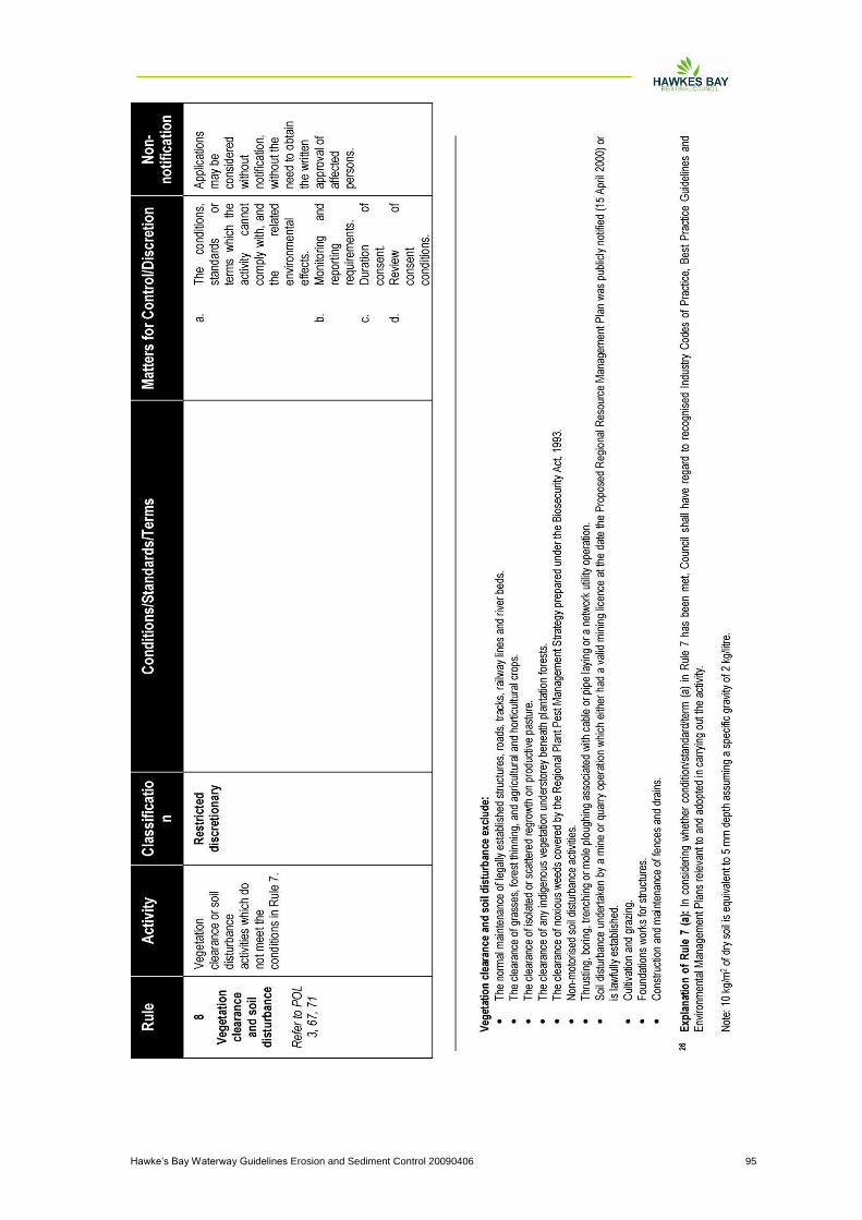
Hawke‟s Bay Waterway Guidelines Erosion and Sediment Control 20090406 95