have you p3006 - automotive tech info
TRANSCRIPT

Also inside: Monitoring the ProblemPutting the Heat on 'emthe bimmer pub speacial feature: cushioning the blow
May 2012 Vol.17 No.1
Have you mastered
diagnosis on the
Gen1 Prius?
. . .Are you sure?
P3006
a mastertechmag.com online publication

FIRE...
. . . on all eight with www.startekinfo.com.
Mercedes-Benz USA Dealer Workshop Services is the source for all the technical information needed to support, service, and maintain Mercedes-Benz vehicles. Mercedes-Benz workshops rely on DWS products and services for getting jobs done quickly and more efficiently. Our products include:
STAR TekInfo Dealer Workshop ServicesEngineering Services, Mercedes-Benz USA, LLC.
s STAR TekInfo with WIS-net (Workshop Information System)s Electrical Troubleshooting Manualss Installation Instructionss Technical Bulletinss Campaignss Mercedes-Benz Special Tools
s Maintenance Manuals and Sheetss STAR Service Manual Library CDss WIS and DAS software updatess Star Diagnosis System (SDS)s Operator’s Manuals and COMAND Manualss Mercedes-Benz Equipments Inventory of technical publications

Christopher M. Ayers, Jr.President/[email protected]
Ralph Birnbaum • Steve Campbell Paul Cortes • Kerry Jonsson Phil Fournier • Chip Keen Greg McGoniga • Tony Molla Tom Nash • Henry Olsen Dave RussContributing [email protected]
Joann TurnerCirculation [email protected]
Christopher Ayers IIIArt Director, Web [email protected]
Editorial, Circulation, Advertising Sales & Business Office:Import Service Magazine134B River RoadMontague NJ 07827P.330.620.3929 F.330.666.8912
If you have a letter to the editor, a Tech Tip or story idea, click here: [email protected], or on our website at www.mastertechmag.com.
The publisher and editors of this magazine accept no responsibility for statements made herein by advertisers or for the opinions expressed by authors of bylined articles or contributed text.
The online version of Import Service magazine is free for a limited time to qualified automotive repair shop owners, managers and technicians. All other content on www.mastertechmag.com - with the exception of Master Technician Magazine ONLINE, which will remain free to qualified repair shop owners, managers and technicians - is avail-able on a subscription basis.
CO
NT
EN
TS
Putting the Heat On ‘Emby Kerry JonssonJust because you put on a new part doesn’t mean it’s going to fix the problem. Such was the case with this Toyota Camry that had a fresh O2 sensor.
14
Monitoring the Problemby Kerry JonssonEvery so often we run into the problem of not having a problem to solve. What do we do when we have a vehicle that is not setting codes, but it is also not running OBD II monitors...
04
Feature
26P3006 Diagnosisby Paul CortesPaul gets to enjoy practicing his old-fashioned soldering skills and saves his customer lots of money.
Cover Story
May 2012 Vol.17 No.1
Cushioning the Blowthe bimmer pub Special FeatureAmong the greatest safety advancements are BMW’s various types of supplemental restraint systems. Here are some service procedures you should know about.
38

Import service | www.mastertechmag.com4
When we were young and learning how to diagnose fuel-injected engines, all the old timers would beg for a carbureted vehicle to diagnose. In later years as we all got more familiar with fuel injection, we would all complain, “Oh no, I have to diagnose a carbureted engine? Give me
Every so often we run into the problem of not having a problem to solve. What do we do when we have a vehicle that is not setting codes, but it is also not running OBD II monitors. They need to run so the car can pass our state inspection program. Well, this Honda gave us plenty not to solve, so how did we do it?
Monitoring
by Kerry Jonsson
The
Problem
fuel injection!” Our biggest problem was that each manufacturer had its own ways of doing things. We had to learn many different systems both domestic and foreign. We had to know GM, Ford, and Chrysler, plus Asian and European engine management systems. Remember those days?

May 2012 | Import service 5
Published: May 4, 2012 | Keyword: Monitor OBD
Then OBD II came along in the mid-nineties and that was going to fix everything. All the manufacturers were going to have their diagnostic software speak the same language. Didn’t that just work out great? We can’t wait for OBD III! (we hope you’re catching our drift). One of the great accomplishments of OBD II was the setting up of “monitors,” which would run or not according to the system’s whims.
Self-diagnostic ability was built into each engine management computer. It would monitor the input sensor values and output solenoid controls and make sure each component of each system was functioning properly. Some of these systems are monitored continuously (all the time), and others are not monitored continuously (non-continuous), but are tested as the vehicle completes a “drive cycle.”. Three monitors are continuous: the misfire monitor, the fuel system monitor,
The PH2 software has you start off with a Validation session. Here it simply clears the codes and reports any pending codes. You are instructed to drive the vehicle 7 ½ minutes at 45mph and another 7 ½ minutes at 55mph for best results.
and the comprehensive component monitor. The PCM is always watching crankshaft speed for misfires. Misfires can lead to increased harmful emissions and destroy the cat. The fuel injection

Import service | www.mastertechmag.com6
Monitoring the Problem
feedback system is also monitored to see if the vehicle is running too rich or too lean, which may also lead to an increase in air pollution. Finally, the comprehensive component monitor looks at input signal voltages to make sure they make sense, and at all of the output voltages to make sure the computer can control the system.
Non-continuous monitors are tests the PCM performs on a system while the vehicle is running and certain conditions are met. Although the EPA would probably like it if an engineer would test the O2 sensor while the engine is under the heavy load of acceleration while going up a hill, that wouldn’t be fair to the O2 sensor. A rich condition is required under load. However, most of us do not spend all our time driving uphill. On a flat and steady road, the engineer can have the PCM check its systems since all of the input sensor readings are stable as the vehicle cruises along. The PCM’s fuel control system can watch the O2 sensor signal voltage and make sure it is switching between rich and lean within a specific time frame. If it is, the O2 sensor passes the test and the monitor will indicate that it has run and passed. If not, then the monitor will indicate a failure, and after a second running flag a code.
Well, it’s one thing to have a vehicle come in with a flagged DTC. All we have to do is scan the PCM for DTCs and look up the code in our information system. We are
often rewarded with a flow chart outlining test procedures we can follow, use our personal experience to test the system that has the fault and/or, dare I say, just wing it and replace something that’s likely to fix the problem. There are many ways we can approach the problem. Some are the long way and others are the short way, but we each have our own way. After the repair, we can retest the system and verify that it worked. Sometimes, particularly with intermittent problems, we have to wait to find out while our customers drive the vehicle we repaired. As the PCM runs its monitors, it will either pass or fail depending on the accuracy of our diagnosis and repair.
It’s another thing when we do not have any DTCs. There may not even be a drivability problem that our customer is complaining about. But if the car has to go to a motor vehicle inspection facility and these monitors have not run, the owner may get a “tsk, tsk, tsk . . .” from the inspector, who might believe someone has cleared the DTCs and tried to sneak the vehicle through inspection. The fact that the monitors have not run might make the inspector suspect that the owner is trying to hide some failure. The vehicle has to be driven and these monitors have to run to completion in order for the state to okay the emissions portion of the inspection program. If the monitors have not run, you have to keep driving until they do.

May 2012 | Import service 7
Get better performance from
a cleaner engine with BMW Group
Fuel System Cleaner Plus.
To get the most performance, fuel efficiency - and fun - from every mile, and for optimum cleaning of fuel injectors and intake valves, use one (20 fl.oz.) bottle of BMW Group System Cleaner Plus every 3,000 miles when refueling.
BMW Group Fuel System Cleaner Plus uses TECHRON® Technology developed and patented by Chevron.
For complete information, includiing prices and availability, and to order Original BMW Group Fuel System Cleaner Plus, contact your local BMW center.
TECHRON is a trademark owned by Chevron Intellectual Property LLC.
Detergent additives have been required
by the EPA in gasoline since 1995 to
control the formation of engine and fuel
system deposits. Lower quality gasoline
is formulated with less effective and
less expensive detergent additives.
Over time, even occasional use of this
gasoline robs your engine of its power,
performance and fuel efficiency.

Import service | www.mastertechmag.com8
Monitoring the Problem
Some states allow a grace period, which gives the owner enough time to drive the vehicle legally until the monitors run.
But what happens after “saying grace” and the monitors still haven’t run? That was the case with the 2001 Honda Accord with a 2.3L four that’s our subject here. It came in and some work needed to be done for it to pass inspection. After the work was done it still had a problem. It was not flagging any DTCs, but it was also not running its monitors to completion. None of the monitors ran -- not one! So where were we going to start? We did not have a code and there was no drivability problem to diagnose. We may have a bad PCM, so can we trust the data we’re getting? We tried using the vehicle-specific software in our aftermarket scan tool, but we didn’t find any codes there, either. We could’ve started by looking at data to see if something seems unusual to us, but if nothing leapt out at us, what were we going to do?
We decided to do some simple testing of the engine management system. We like to start off with the basics and make sure we are not missing something obvious. Fuel pressure first, which is not easy. There are
no pressure tap Schraders on the rail of this vehicle. With the proper adapters, we could have tapped into the banjo bolt that brings the fuel pressure into the rail, but we decided that since the vehicle was on the lift and we were going to change the fuel filter anyway, we would connect our Motor Vac machine to the fuel filter. Unfortunately, we had a perfectly reasonable 40 psi. After changing the filter, we moved on to a basic manifold vacuum test and found we had a
When we looked at the generic data the PH2 supplied, we noticed that long-term fuel trim was subtracting about 8% due to the rich condition. Not enough to flag a code, but enough to interrupt the monitors and keep them from running.

May 2012 | Import service 9
very normal 20 in. Hg at idle with no load -- nothing wrong here. We moved on to sensor readings. We compared the MAP sensor voltage to the MAP sensor we were seeing. Typically, a good MAP sensor will read 2.9V with the key on and the engine off and .9 to 1.0V idling with 20 in. HG in the manifold. This reading may vary depending on your altitude, but for us these were normal numbers. We looked at the coolant sensor to make sure the engine was getting up to temperature, and it was. Just idling, it went up to 205 deg. F., so we knew the thermostat was closing properly and keeping the engine up to temperature. We checked the TPS signal voltage and saw that it read about .75V closed. We did not know if this was normal, but the PCM was not flagging a TPS code or an idle too high or too low code. We needed to find some answers.
We did have a unique tool just for situations like this. It is called PH2 Solutions. It is a software program and special OBD II cable that connects to the USB port of your PC. It is also available already installed on a laptop computer. This tool has some unique features. It is not a manufacturer-specific scan tool. It communicates with the PCM using one of the generic OBD II protocols of the car it is plugged into. It can work well as a generic scan tool. It can pull codes and pending codes and clear them. It can also tell you which monitors have run and which ones have not. Its most important task is to tell you what “conditions” the PCM is looking at while it is deciding which monitors to run to completion and which ones it will not.
With nothing else to go on, we decided to try out our new tool. There are two applications. The first is the Drive Cycle Validator. Using this function you are instructed to drive the vehicle on a
You can run a Data Analysis session and review your findings after the road test. Here you can see in red that the O2 sensor voltage was not switching (it was stuck rich) while at idle and when the engine was revving. This led us to check the TPS voltage at idle again.

Import service | www.mastertechmag.com10
Monitoring the Problem
15-minute road test with the Drive Cycle software running. An ideal road test would be about 7 ½ minutes at 45 mph, then increase speed to 55mph for another 7 ½ minutes. In the Drive Cycle software is a clock that lets you know how long the session is running. Some vehicles may require more driving, but the Drive cycle software will let you know right away which monitors have already run and if there are pending or hard codes that have set in the PCM. The drive cycle is also a good way to verify a repair right away instead of returning the vehicle to the customer and seeing if the code comes back.
The second part of the PH2 Solutions program is called the Data Analysis Session. This actually provides feedback while you are driving the vehicle. Once you start the analysis, the software starts analyzing frames of data. These frames are broken down into Idling, Revving (acceleration), Driving (steady cruising speed), and Coasting. This helps you isolate when the problem is occurring. If your problem is at idle, you only need to test the vehicle at idle. In the lower “Issue Indicator Event” field, you are informed of the condition that is interfering with the running of the monitors. This is a tremendous help when dealing with a vehicle that will not run
monitors. The PH2 software is not going to run the monitor for you as you can on Audis and Volkswagens, for example, but it does tell you the conditions that are interfering with running the monitors. These conditions may not be so severe that they flag a code.
We started a data analysis session and went for a road test. We immediately saw what we thought was the problem. The first messages we received indicated that the coolant temperature and air temperature were too low to run any monitors. We have heard in the past of thermostats sticking
Had we noticed the high idle speed, we might have caught this problem sooner. The PCM did not flag any codes for a high idle, probably because the TPS voltage was .75V. The PCM simply thought someone was stepping on the throttle all the time.

May 2012 | Import service 11
GENUINE Foreign Nameplate Parts
Beck/Arnley has added a premium line of genuine OE fluids for Asian vehicles to go along with its premium line of genuine foreign nameplate parts. With our unique application specific sourcing, which comes directly from the chemical suppliers who supply the OEMs, Beck/Arnley’s fluids are performance enhancers which will keep your customers’ engines running like new.
Not all aftermarket fluids are created equally. Trust the brand that also provides the best premium genuine foreign nameplate parts.
Keep Your Business Flowing with Beck/Arnley OE Fluids.
GENUINE
F LU I DOEOE
TM
www.beckarnley.comTo place an order today call 1-888-GO4BECK (1-888-464-2325).
The Best Name on a Box is Now
the Best Name on a Bottle

Import service | www.mastertechmag.com12
Monitoring the Problem
open and allowing the engine temperature to drop while driving down the road. We called their technical support specialist and found that the vehicle needs to be properly warmed up before you can start the analysis. We then allowed the vehicle to idle for 15 minutes to get the engine to full operating temperature. Once we did this and ran the session again the coolant and air temperature messages went away, but at least we knew the software was working. We now went on another road test and started to see the real cause of the problem -- we were rewarded with usable results.
The first message we saw was “Bank 1 Oxygen Sensor 1 voltage not switching.” We did not have O2 sensor codes, but our PH2 was telling us the oxygen sensor voltage was not switching between rich and lean. The problem was happening at idle. We needed to continue the road test to see if the problem also occurred during acceleration, cruising, and on deceleration. During the road test there were no messages telling us about any problems with driving conditions, but when the vehicle returned to idle the message “voltage not switching” returned. So, we at least knew the problem was only
at idle. We now had something we could start looking for. We did not think we had a mixture problem at idle, but apparently we did. We kept the engine at idle and started looking at O2 sensor activity and fuel trim readings. We were surprised with what we found.
The next step was to look at scan data. We would normally put an oscilloscope on the O2 sensor signal wire, but this was
Using the PH2 software, we looked again at our fuel trim data and saw that the long- and short-term fuel trims were 0% on this fully warmed-up engine. At this point the vehicle was road tested and passed all of its monitors and inspection.

May 2012 | Import service 13
an F23A4 motor so it has an Air Fuel Ratio (AFR) sensor. These sensors use milliamps to signal a rich or lean condition and are very difficult to scope. We did find two technical service bulletins from Honda, but both dealt with the tremendous cost of replacing the Air Fuel Ratio sensor, PCM and, in one case, all four injectors. This could have been a costly repair for our customer, so we decided to look at little deeper and see if we could do something else first. A quick look at the fuel trims showed us something we didn’t expect.
We found we could use the PH2 Solutions software as a generic scan tool. Looking under Tools in the Menu bar, you can view a live OBD II data stream. At idle, the fuel trims were unusual. After idling for five minutes, we noticed the long-term fuel trim was about -8% and the short term fuel trim was about -2%. Now we knew why this did not flag any codes. Typically, fuel trims have to shift over 10% +/- to set a code. We were under the limit, but very close to setting a code for an O2 sensor rich condition. We still had to find out what was causing the richness. The TSB having us replacing the injectors was looking like the fix for this one. We could have performed a fuel contribution test for each injector, but what if they all flowed the same?
We went back over our sensor readings and the only one we were not sure of was
the TPS. We looked up the DTC for the TPS and Honda specifications told us the voltage should be about .5V, but we were at .75V. Now, you cannot change the TPS on a Honda. They sell the TPS with the whole throttle body. The TPS is riveted and the mounting holes are not slotted, so you cannot adjust it. I don’t recommend this as a repair, but as a simple, quick way to test the system after making a change. We bent the throttle tab until the TPS voltage indicated .5V. We then disconnected the battery to reset the fuel trims to 0%. After an extended idle both fuel trims remained at 0% at a normal idle speed of 900 rpm.
Admittedly, we had never noticed the abnormally high idle speed of 1,100rpm. But remember, the PCM did not flag a P0506/P0507, either. They did not even show up as pending codes! We found that our new tool, the PH2 Solutions, pointed us in the right direction when we did not have any direction. It caused us to take a closer look at what conditions were not being met to run the all-important O2 sensor monitor. Once the TPS voltage was corrected, the idle speed returned to normal and so did the fuel trims. In the state of New Jersey, 2001 and later vehicles need to have all but one monitor run to pass the state inspection process. This Honda finally passed with flying colors once the throttle body was replaced and the TPS voltage was back within specifications. Now who would have thought of that?

Import service | www.mastertechmag.com14
My old friend Ray once told me, “Do you know what NEW stands for? Never Ever Worked.” Just because you put on a new part doesn’t mean it’s going to fix the problem. Such was the case with this Toyota Camry that had a fresh O2 sensor.
Putting the
by Kerry Jonsson
Heat On 'Em

May 2012 | Import service 15
People have their own approach to doing things. I’m no different. While I try to improve my diagnostic processes, mistakes are made along the way. I have to admit my mistakes and learn from them. I really have to think about why I made the mistake and realize there were probably a few more tests I could’ve performed before I started changing parts. But this is a business and sometimes I don’t have the time to test everything to death. Some testing is very time consuming indeed. It is hard enough to get paid for my diagnostic
time in this tough economy, and the ones who are willing to pay won’t be
for long if it takes two and three visits for the same problem.
Most of us operate in the middle of the two extremes. Some of us pull a code, do minimal scan-tool testing, and go
to our trusted information source and look at the “top ten
list” of parts that are typically needed to fix the problem. Some of us follow the
DTC flow chart, do some detailed testing, and, if all else fails, consult a pattern failure diagnostic database.
If you’re reading this, you’re probably in the latter category. You read these articles to acquire some technical knowledge about a particular system, or you may just want to learn from what someone
Published: April 13, 2012 | Keyword: O2 Sensor

Import service | www.mastertechmag.com16
Putting the Heat on 'Em
else went through. Either way, you want to improve your knowledge base. We applaud you. There is very little continuing education in our field. Once every few months automotive technical conventions with training classes come along, but with the rate at which new systems are put on vehicles it’s almost impossible to keep up with the changes. But the responsible among us do what we can.
The subject here, a 2003 Toyota Camry, presented a problem that might have been taken care of in five minutes instead of five hours. It all started on a warm winter day (the North east didn’t get hit with much cold or snow this year). The first tech to look at the vehicle was told that the “check engine light” (more accurately called a “MIL” for “Malfunction Indicator Lamp”) was on and immediately “scanned” for DTCs (actually, you “read” codes, and “scan” for data). He was rewarded with a few. In many states that have vehicle inspection programs, car owners will drive around with the MIL on if their automotive repair shop says it’s okay. Then, when it’s time to do the inspection other problems may have come up.
There was a P0032 and a P0128. The first means the coolant is taking too long to get to the temperature the engine management system requires to go into closed loop. In most cases, this would be a weak or stuck-open thermostat, but this
While measuring the amp draw of the first replacement sensor, I noticed the reading was changing from about .5 amp (Top) to 1.8 amps (Bottom) for a few minutes before it flagged a code. Once the code was set, the amperage disappeared since the PCM stopped grounding the circuit.

May 2012 | Import service 17
time the coolant level was a little low, so I pressure tested the system, found a small leak, and replaced a hose with new clamps. In the interest of self-preservation, I decided to sell a thermostat. There is little that is more difficult to do than to explain to a customer that the MIL came on again right after you repaired the vehicle, but that this time it’s a different problem. You and I know that any given vehicle can flag any number of hundreds of codes, but try explaining that to the man. It was safer to replace the thermostat, flush the cooling system, and refill it with the
correct coolant mixture. In the future, if you would like to know how to diagnose a P0128, you can start by monitoring the coolant temperature sensor signal voltage for 15 to 20 minutes and see how far the signal voltage drops, but you would need some experience with the characteristics of the engine you are working on.
You can also watch the CTS voltage fluctuate when hot. It should remain stable while the engine is running. I’ve noticed that a weak thermostat opens and closes in wider swings and at lower temperatures than normal, so the CTS signal voltage moves up and down more than with a new thermostat. As with most customers around here, this one needed the car for the weekend and would bring it back if needed. I didn’t have the time to let the vehicle cool down to properly test the warm-up period. The engine started right up, so it was not a life-or-death situation. The customer just wanted the vehicle to pass inspection, which is not unreasonable.
I still had the second code to deal with. A P0031 indicates that the heater circuit voltage is low for the bank 1, sensor 1. If you go through the flowchart for this code, one of the first tests it has you perform is to check the resistance of the heater circuit. I could have gone to the PCM to check this, but in the interests of time I simply checked the resistance of the heater right at the O2 sensor connector.
The first replacement sensor measured four ohms of resistance. I didn’t compare this reading to the flow chart, which cost me some unpaid diagnostic time. I should’ve listened to Ray.

Import service | www.mastertechmag.com18
Putting the Heat on 'Em
What I found was no resistance at all. The meter read “OL,” which means “Out of Limits.” You don’t have to be an expert diagnostician to know that an open circuit is probably going to set a code from the comprehensive component monitor in the PCM. This was a fairly simple diagnosis. The heater circuit in the O2 sensor itself was open. A sensor was promptly ordered and installed. Some shops stop right there. They return the vehicle to the customer and let him or her drive it to see if the MIL
comes back on. Not anyone who’s reading this article, I hope. The vehicle was taken out on a test drive and codes were checked again. Unfortunately, the MIL came back on, and now there was a code P0032.
With time running short, another sensor was ordered and installed. Once again, the code returned during the road test. I was starting to get worried that the O2 sensor heater driver in the PCM might have been damaged by the old sensor.
We pulled the flowchart and found that the first step was to check sensor resistance. We skipped this step with our new sensor since we assumed a new sensor was supposed to be the solution, not the problem (Courtesy Alldata, Inc.).

May 2012 | Import service 19Nissan & Infiniti Tech News | 21
NissanTechNewsAugust2011:MarchStarTuned2005 8/8/11 2:06 PM Page 21
Import service | www.mastertechmag.com20
Putting the Heat on 'Em
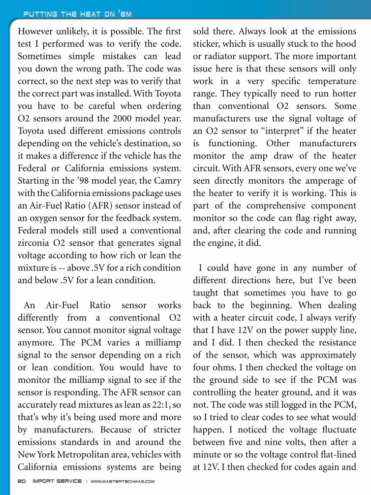
However unlikely, it is possible. The first test I performed was to verify the code. Sometimes simple mistakes can lead you down the wrong path. The code was correct, so the next step was to verify that the correct part was installed. With Toyota you have to be careful when ordering O2 sensors around the 2000 model year. Toyota used different emissions controls depending on the vehicle’s destination, so it makes a difference if the vehicle has the Federal or California emissions system. Starting in the ’98 model year, the Camry with the California emissions package uses an Air-Fuel Ratio (AFR) sensor instead of an oxygen sensor for the feedback system. Federal models still used a conventional zirconia O2 sensor that generates signal voltage according to how rich or lean the mixture is -- above .5V for a rich condition and below .5V for a lean condition.
An Air-Fuel Ratio sensor works differently from a conventional O2 sensor. You cannot monitor signal voltage anymore. The PCM varies a milliamp signal to the sensor depending on a rich or lean condition. You would have to monitor the milliamp signal to see if the sensor is responding. The AFR sensor can accurately read mixtures as lean as 22:1, so that’s why it’s being used more and more by manufacturers. Because of stricter emissions standards in and around the New York Metropolitan area, vehicles with California emissions systems are being
sold there. Always look at the emissions sticker, which is usually stuck to the hood or radiator support. The more important issue here is that these sensors will only work in a very specific temperature range. They typically need to run hotter than conventional O2 sensors. Some manufacturers use the signal voltage of an O2 sensor to “interpret” if the heater is functioning. Other manufacturers monitor the amp draw of the heater circuit. With AFR sensors, every one we’ve seen directly monitors the amperage of the heater to verify it is working. This is part of the comprehensive component monitor so the code can flag right away, and, after clearing the code and running the engine, it did.
I could have gone in any number of different directions here, but I’ve been taught that sometimes you have to go back to the beginning. When dealing with a heater circuit code, I always verify that I have 12V on the power supply line, and I did. I then checked the resistance of the sensor, which was approximately four ohms. I then checked the voltage on the ground side to see if the PCM was controlling the heater ground, and it was not. The code was still logged in the PCM, so I tried to clear codes to see what would happen. I noticed the voltage fluctuate between five and nine volts, then after a minute or so the voltage control flat-lined at 12V. I then checked for codes again and

May 2012 | Import service 21
there is weren’t any, so I tried to check for pending codes under OBD II generic and there is was, a P0032. This means once I cleared the code I only had a few minutes to monitor the situation before the code flags and the PCM gives up trying to control the ground on the heater circuit. I needed to look a little more deeply into things.
I could see that the PCM was attempting to control the ground of the heater circuit, and, therefore, the amp draw. I wanted to look at the draw to see if it would tell me
Even though this was a California vehicle, I asked my parts supplier to send down several O2 sensors from different aftermarket manufacturers so we could test them until we measured the 1.0 ohm that we needed. I was surprised to find that the Federal sensor was the right one.
anything. Now, to measure amperage you need to connect your DMM in series. This means you cannot just tap into the wire as if you were measuring voltage. I had to open the circuit and connect the test leads to each side of the open circuit. This usually means cutting a wire. Now this is not a terrible thing to do, but you probably do not want to cut into the car’s harness, so you are going to cut either the power or ground wire of the heater circuit of the sensor’s pigtail. It doesn’t matter which wire you measure the amp draw on since both sides will read the same amperage. You just have to remember to connect your leads following the direction of current flow or you’ll get a negative reading. I have a low-current inductive probe, and I find it works pretty well compared to a DMM. I saw the amperage oscillate between .5 and 1.8 amps. These seemed to be normal readings but I needed something to compare them to. I felt it was time to pull out the big guns.
I wanted to see what the PCM was doing to manage the situation. I pulled out my oscilloscope, tapped into the ground side of the heater circuit, and cleared the code once again. What I saw was interesting. The PCM did try to ground the heater. I set up the trigger on the scope and could catch one on/off cycle of the heater control. I could see the duty cycle to ground was moving back and forth between 20% and 80%. The PCM made several attempts
Import service | www.mastertechmag.com22
Putting the Heat on 'Em
at increasing the duty cycle (to ground) from 20 to 80 percent until finally giving up. The scope signal flat-lined at 12V again and the PCM flagged a code for the O2 sensor heater circuit. This told me several things. The ground control pattern looked clean. The voltage signal dropped down from 12V cleanly to ground and returned to 12V cleanly. No irregularities in the pattern at all. If I had seen an erratic pattern, I may have concluded that the PCM driver could not control the heater circuit properly. This pattern told me the PCM driver seemed to be in good shape. I was going to have to try a few more things before I replaced the PCM.
I was starting to get worried. Nothing in my testing jumped out at me to say, “Pick me, I’m the problem.” I dreaded telling the customer he needed a new PCM after selling him the idea of a thermostat and an O2 sensor. If you have to look at a problem too deeply, chances are you missed something. When it doubt go back to the beginning. This is something I should have done several tests ago. I went to my information system and pulled up a flow chart for the code. In reviewing the testing, I noticed the first step of the test was to measure the heater resistance on the sensor, which should be between .9 and 1.2 ohm. If you remember (and I didn’t right away), it measured 4.0 ohms. I did verify this as a California emissions vehicle and I did order the correct sensor
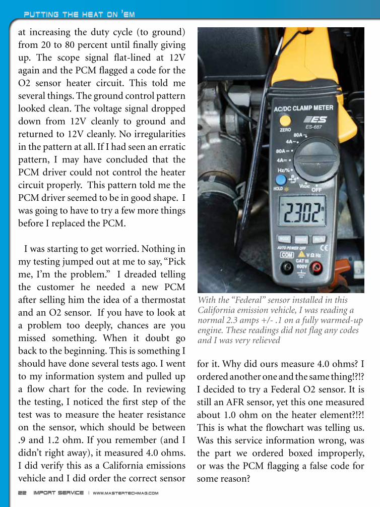
With the “Federal” sensor installed in this California emission vehicle, I was reading a normal 2.3 amps +/- .1 on a fully warmed-up engine. These readings did not flag any codes and I was very relieved
for it. Why did ours measure 4.0 ohms? I ordered another one and the same thing!?!? I decided to try a Federal O2 sensor. It is still an AFR sensor, yet this one measured about 1.0 ohm on the heater element?!?! This is what the flowchart was telling us. Was this service information wrong, was the part we ordered boxed improperly, or was the PCM flagging a false code for some reason?

May 2012 | Import service 23
The cheapest option was to just try the Federal AFR sensor. Guess what? The draw stabilized at 2.3 amps and the PCM did not flag a heater code after five minutes of running. The duty cycle on the heater circuit stabilized at approximately 25%. After the road test there were no pending codes and no two-trip codes. Simply checking the resistance of the new part would have brought us here a lot sooner, but hindsight is 20/20. It would have been easy to verify the resistance compared to the flowchart when the part came in, but I put the flowchart down when the new
The Finishing TouchIn Customer Service!
SPACE EFFICIENT Different models to fit almost any space
QUALITY WASHING Thirty years of proven history
QUICKER RESULTS Complete wash in 2 minutes or less
EASY TO USE OPERATION Simple operation increases efficiency
LASTING DURABILITY Aluminum frame provides durability
Broadway Car Wash Equipment CompanyPartners with the Autohaus Concept!
Broadway Equipment Company • 1-800-976-WASH • www.broadwayequipment.com
SomeofOurNationwideMercedes-BenzPartners:
NewCountryMotorsHartford,CT
W.I.SimonsonMercedesSantaMonica,CA
ScholfieldMotorsWichita,KS
Mercedes-BenzofSanAntonioSanAntonio,TX
Mercedes-BenzofSmithtownSaintJames,NY
part arrived. I talked to a Toyota dealer and found that when ordering AFR sensors they always ask for the part number on the sensor itself. This avoids any confusion when ordering AFR sensors. I don’t know if the catalog was wrong, the part was in the wrong box, the counterman got it wrong, or all the planets were simply aligned against me. But I was finally able to deliver the vehicle that night without replacing a PCM, but I did have to go through a few O2 sensors before I got the right one. “You know what NEW stands for?, Never Ever Worked!” Go figure.
Import service | www.mastertechmag.com24
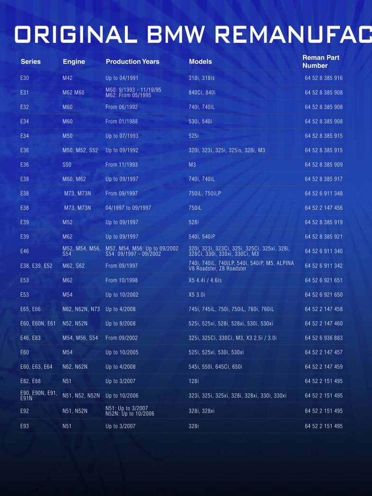
Series Engine Production Years ModelsReman Part Number
E30 M42 Up to 04/1991 318i, 318is 64 52 8 385 916
E31 M62 M60 M60: 9/1993 - 11/19/95 M62: From 05/1995 840Ci, 840i 64 52 8 385 908
E32 M60 From 06/1992 740i, 740iL 64 52 8 385 908
E34 M60 From 01/1988 530i, 540i 64 52 8 385 908
E34 M50 Up to 07/1993 525i 64 52 8 385 915
E36 M50, M52, S52 Up to 09/1992 320i, 323i, 325i, 325is, 328i, M3 64 52 8 385 915
E36 S50 From 11/1993 M3 64 52 8 385 909
E38 M60, M62 Up to 09/1997 740i, 740iL 64 52 8 385 917
E38 M73, M73N From 09/1997 750iL, 750iLP 64 52 6 911 348
E38 M73, M73N 04/1997 to 09/1997 750iL 64 52 2 147 456
E39 M52 Up to 09/1997 528i 64 52 8 385 919
E39 M62 Up to 09/1997 540i, 540iP 64 52 8 385 921
E46 M52, M54, M56, S54
M52, M54, M56: Up to 09/2002 S54: 09/1997 - 09/2002
320i, 323i, 323Ci, 325i, 325Ci, 325xi, 328i, 328Ci, 330i, 330xi, 330Ci, M3 64 52 6 911 340
E38, E39, E52 M62, S62 From 09/1997 740i, 740iL, 740iLP, 540i, 540iP, M5, ALPINA V8 Roadster, Z8 Roadster 64 52 6 911 342
E53 M62 From 10/1998 X5 4.4i / 4.6is 64 52 6 921 651
E53 M54 Up to 10/2002 X5 3.0i 64 52 6 921 650
E65, E66 N62, N62N, N73 Up to 4/2008 745i, 745iL, 750i, 750iL, 760i, 760iL 64 52 2 147 458
E60, E60N, E61 N52, N52N Up to 9/2008 525i, 525xi, 528i, 528xi, 530i, 530xi 64 52 2 147 460
E46, E83 M54, M56, S54 From 09/2002 325i, 325Ci, 330Ci, M3, X3 2.5i / 3.0i 64 52 6 936 883
E60 M54 Up to 10/2005 525i, 525xi, 530i, 530xi 64 52 2 147 457
E60, E63, E64 N62, N62N Up to 4/2008 545i, 550i, 645Ci, 650i 64 52 2 147 459
E82, E88 N51 Up to 3/2007 128i 64 52 2 151 495
E90, E90N, E91, E91N N51, N52, N52N Up to 10/2006 323i, 325i, 325xi, 328i, 328xi, 330i, 330xi 64 52 2 151 495
E92 N51, N52N N51: Up to 3/2007 N52N: Up to 10/2006 328i, 328xi 64 52 2 151 495
E93 N51 Up to 3/2007 328i 64 52 2 151 495
Series Engine Production Years ModelsReman Part Number
E82, E88 N54 From 11/2006 135i 64 52 2 151 496
E90 N54 From 3/2006 335i, 335xi 64 52 2 151 496
E90N N54 From 04/2008 335i, 335xi 64 52 2 151 496
E92 N54 From 06/2005 335i, 335xi 64 52 2 151 496
E93 N54 From 10/2005 335i 64 52 2 151 496
E82 N51, N52N N51: From 03/2007, N52N: From 10/2006 128i 64 52 2 153 227
E88 N51, N52N N51: From 03/2007, N52N: From 10/2006 128i 64 52 2 153 227
E90 N51, N52, N52N N51: From 03/2007 N52, N52N: From 10/2006 323i, 325i, 325xi, 328i, 328xi, 330i, 330xi 64 52 2 153 227
E90N N51, N52N N51: From 03/2007 N52N: From 10/2006 328i, 328xi 64 52 2 153 227
E91 N52, N52N From 10/2006 325xi 328i 64 52 2 153 227
E91N N52N From 10/2006 328i, 328xi 64 52 2 153 227
E92 N51, N52N N51: From 03/2007 N52N: From 10/2006 328i, 328xi 64 52 2 153 227
E93 N51, N52N N51: From 03/2007 N52N: From 10/2006 328i 64 52 2 153 227
Remanufactured for BMW by
Available only through your local BMW Dealer
ORIGINAL BMW REMANUFACTURED A/C COMPRESSORS
* Made with the same OE components as original factory parts
* Assembled to original BMW specifications
* Results: BMW Quality, Reliability and Value

May 2012 | Import service 25
Series Engine Production Years ModelsReman Part Number
E30 M42 Up to 04/1991 318i, 318is 64 52 8 385 916
E31 M62 M60 M60: 9/1993 - 11/19/95 M62: From 05/1995 840Ci, 840i 64 52 8 385 908
E32 M60 From 06/1992 740i, 740iL 64 52 8 385 908
E34 M60 From 01/1988 530i, 540i 64 52 8 385 908
E34 M50 Up to 07/1993 525i 64 52 8 385 915
E36 M50, M52, S52 Up to 09/1992 320i, 323i, 325i, 325is, 328i, M3 64 52 8 385 915
E36 S50 From 11/1993 M3 64 52 8 385 909
E38 M60, M62 Up to 09/1997 740i, 740iL 64 52 8 385 917
E38 M73, M73N From 09/1997 750iL, 750iLP 64 52 6 911 348
E38 M73, M73N 04/1997 to 09/1997 750iL 64 52 2 147 456
E39 M52 Up to 09/1997 528i 64 52 8 385 919
E39 M62 Up to 09/1997 540i, 540iP 64 52 8 385 921
E46 M52, M54, M56, S54
M52, M54, M56: Up to 09/2002 S54: 09/1997 - 09/2002
320i, 323i, 323Ci, 325i, 325Ci, 325xi, 328i, 328Ci, 330i, 330xi, 330Ci, M3 64 52 6 911 340
E38, E39, E52 M62, S62 From 09/1997 740i, 740iL, 740iLP, 540i, 540iP, M5, ALPINA V8 Roadster, Z8 Roadster 64 52 6 911 342
E53 M62 From 10/1998 X5 4.4i / 4.6is 64 52 6 921 651
E53 M54 Up to 10/2002 X5 3.0i 64 52 6 921 650
E65, E66 N62, N62N, N73 Up to 4/2008 745i, 745iL, 750i, 750iL, 760i, 760iL 64 52 2 147 458
E60, E60N, E61 N52, N52N Up to 9/2008 525i, 525xi, 528i, 528xi, 530i, 530xi 64 52 2 147 460
E46, E83 M54, M56, S54 From 09/2002 325i, 325Ci, 330Ci, M3, X3 2.5i / 3.0i 64 52 6 936 883
E60 M54 Up to 10/2005 525i, 525xi, 530i, 530xi 64 52 2 147 457
E60, E63, E64 N62, N62N Up to 4/2008 545i, 550i, 645Ci, 650i 64 52 2 147 459
E82, E88 N51 Up to 3/2007 128i 64 52 2 151 495
E90, E90N, E91, E91N N51, N52, N52N Up to 10/2006 323i, 325i, 325xi, 328i, 328xi, 330i, 330xi 64 52 2 151 495
E92 N51, N52N N51: Up to 3/2007 N52N: Up to 10/2006 328i, 328xi 64 52 2 151 495
E93 N51 Up to 3/2007 328i 64 52 2 151 495
Series Engine Production Years ModelsReman Part Number
E82, E88 N54 From 11/2006 135i 64 52 2 151 496
E90 N54 From 3/2006 335i, 335xi 64 52 2 151 496
E90N N54 From 04/2008 335i, 335xi 64 52 2 151 496
E92 N54 From 06/2005 335i, 335xi 64 52 2 151 496
E93 N54 From 10/2005 335i 64 52 2 151 496
E82 N51, N52N N51: From 03/2007, N52N: From 10/2006 128i 64 52 2 153 227
E88 N51, N52N N51: From 03/2007, N52N: From 10/2006 128i 64 52 2 153 227
E90 N51, N52, N52N N51: From 03/2007 N52, N52N: From 10/2006 323i, 325i, 325xi, 328i, 328xi, 330i, 330xi 64 52 2 153 227
E90N N51, N52N N51: From 03/2007 N52N: From 10/2006 328i, 328xi 64 52 2 153 227
E91 N52, N52N From 10/2006 325xi 328i 64 52 2 153 227
E91N N52N From 10/2006 328i, 328xi 64 52 2 153 227
E92 N51, N52N N51: From 03/2007 N52N: From 10/2006 328i, 328xi 64 52 2 153 227
E93 N51, N52N N51: From 03/2007 N52N: From 10/2006 328i 64 52 2 153 227
Remanufactured for BMW by
Available only through your local BMW Dealer
ORIGINAL BMW REMANUFACTURED A/C COMPRESSORS
* Made with the same OE components as original factory parts
* Assembled to original BMW specifications
* Results: BMW Quality, Reliability and Value

Import service | www.mastertechmag.com26
Have you mastered
diagnosis on the
Gen1 Prius?
P3006 diagnosis on the Gen1 Prius
Are you sure?
P3006

May 2012 | Import service 27
One of the chief benefits of previous experience with a pattern problem is the ability to make short work of its diagnosis. The effort you put in struggling through your first couple of exposures pays dividends on subsequent encounters. Once a system is committed to memory through first-hand experience, you can diagnose with just a quick skim of the manual, or maybe no reading at all. When a familiar pattern begins to emerge, you’ll know what to do and the quickest way to do it, giving you a distinct advantage.
Faster diagnostic time can mean more money for you, or your customer, but usually a combination of both. Charging less and earning more is a win-win. You’re a hero to your customer, making good profit, and everything is good in the world.
So, when you see a P3006 (Battery levels unusually different) for the umpteenth time, it may be tempting to skip over the relatively easy diagnostic steps, and use an even easier self-created flow chart:
1. Is P3006 stored? Yes.
2. Is Delta SOC% over 20%? Yes.
3. Must be a bad battery pack, because that’s what it has been the last 20 times I’ve seen a P3006.
4. Diagnosis done. Profit!
Paul gets to enjoy practicing his old-fashioned soldering skills and saves his customer lots of money.
by Paul Cortes
Published: April 13, 2012 | Keyword: O2 Sensor

Import service | www.mastertechmag.com28
P3006 diagnosis on the Gen1 Prius
If you have no idea what P3006 is, or what Delta SOC% means, don’t worry. I’ll be briefly explaining the basics P3006 diagnosis, then exploring one of several cases where being a little too arrogant and lazy could have taken me from hero to zero pretty quickly.
A quick review of the basics
The Gen1 Prius has a 274V battery pack made up of 38 7.2V batteries wired together in series. Battery voltage is monitored every two batteries, and can be viewed in the Datalist as battery blocks 1 through 19. Current flowing to and from the battery pack is monitored with a current sensor, and battery temperature is monitored with five temperature sensors inside the battery case. The Battery ECU uses these primary inputs to determine the batteries’ state of charge and state of health, and then shares this information with the HV ECU to help guide its decisions.
P3006 is a common trouble code for the HV Battery ECU. It usually occurs somewhere beyond 100,000 miles on the Gen1 Prius. The newest of the Gen1 Priuses are now nine years old, so almost all of them are candidates for HV battery problems.
Typically, a P3006 will be accompanied by a P3000 in the HV ECU, and a P3011-P3029
in the HV Battery ECU. The P3000 is usually only an indication that there is a trouble code stored in the HV Battery ECU, so when both a P3000 and a P3006 are stored, I tend to ignore the P3000.
P3011-P3029 are codes that point to a specific battery block that is bad. A battery block is two 7.2V batteries tied together in series and monitored as a block by the HV Battery ECU. Attempting to replace an individual battery block is futile. I was told this long ago by a fellow who knows more than I do, and chose to ignore it. If you enjoy Whack-a-Mole, go ahead and experiment for yourself. Focus on the P3006, and think of the battery pack as a whole.
The "normal" diagnosis
There have been several articles (including my own), as well as classes, where P3006 diagnosis has been discussed. Since the information is already out there, and this article is focusing on the exception to the common diagnostic conclusion, I’ll keep this section very brief.
Diagnosis of a P3006 is basically a load test of the battery pack. The load for the test is provided by MG2, the main motor/generator that captures power during regen braking, assists or provides power for forward movement, and is the sole provider


Import service | www.mastertechmag.com30
P3006 diagnosis on the Gen1 Prius
using MG1 to recharge the pack. So the test goes like this:
1. Set the Techstream up to record the HV Battery ECU PIDs
2. Ready the car and put it into reverse while holding the brake.
3. Wait for the ICE to stop (usually around 60% SOC)
4. Step on the accelerator to load the battery pack until the ICE starts again
5. Graph the recorded data and check the spread between BATT BLOCK MIN V and BATT BLOCK MAX V. It should not exceed 1.2V and is usually less.
Delta state of charge, listed as DELTA SOC% in the data list, is the difference in the calculated state of charge between the lowest pair of batteries and the highest pair of batteries. This PID represents the highest difference measured, not the current difference. Delta state of charge PID starts at 20%; differences under 20% are not displayed. DELTA SOC% should always be 20% if the battery pack is healthy.
Atypical problems
That covers the basics of “normal” P3006 diagnosis. Now, let’s take a look at
of power in reverse. The battery is loaded by putting the car in reverse, and stepping on the gas and brake at the same time.
Just as in a standard battery load test, the voltage is monitored while the battery is under load, but instead of monitoring the total battery voltage, the 19 individual block voltages are monitored. The idea is that if all of the cells have equal capacity, their voltages should remain similar while being subjected to strain.
To make simultaneously monitoring 19 PIDs easier, the HV Battery ECU has two PIDs to make the job more human-friendly: BATT BLOCK MIN V and BATT BLOCK MAX V. These PIDs represent the highest measured block voltage and the lowest measured block voltage; they do not correspond to any particular block number. For example, the MIN V may be the voltage reading for BLOCK 1 one moment, and BLOCK 12 the next. This provides an easy way for a technician to monitor the spread between the block with the highest voltage versus the block with the lowest voltage without trying to scan 19 PIDs at the same time.
The maximum separation between the lowest and highest block usually occurs at the end of the load cycle, which is about 40% SOC (State Of Charge). When the battery SOC% reaches 40%, the ICE (Internal Combustion Engine) will start

May 2012 | Import service 31
how P3006 diagnosis can get a little tricky.
So, when is a separation between the minimum block voltage and the maximum block voltage not a problem with the battery? Well, have you ever made a bad connection with the test lead of your voltmeter? A bad back-probe connection can really screw up a diagnosis! The HV Battery ECU is monitoring block voltages via sense wires, which are much like the leads on
This graphed data is from a typical bad battery pack.
Toyota calls a sudden jump and recovery in battery voltage a swing. A voltage swing should not exceed 2V. If it does, Toyota says to replace the HV battery ECU.

Import service | www.mastertechmag.com32
P3006 diagnosis on the Gen1 Prius
a voltmeter. A bad connection on the bus bar or in the HV Battery ECU will fool it into believing the pack has a problem. A smart tech will always confirm a failed test by testing in another way. The HV Battery ECU is not that smart.
The difference between a bad battery and a bad connection can be observed from the comfort of the driver’s seat using the same data and graph created for P3006 diagnosis. What we’re looking for is large jumps in the MIN BLOCK or MAX
The Gen1 Priuses had trouble with leaking electrolyte around the terminals. The HV batteries were recalled, removed, disassembled, cleaned, and resealed with varying degrees of success -- I would call this effort unsuccessful. There is heavy corrosion on the bus bar that ties the batteries together in series, but more importantly in this case, there is heavy corrosion on the sense wire.
BLOCK voltages. Little jumps in battery block voltages are normal. Remember that the MIN and MAX blocks are not real physical blocks, and the voltages will jump around a bit as it shifts from one block to another. However, large rapid jumps usually indicate a connection or ECU problem, rather than a battery problem. Toyota’s flow chart does not acknowledge the possibility of sense wire failure, but it is one of the more common of the atypical causes of P3006 codes.
Save money; do it yourselfThe following is a photo journal of an HV Battery ECU repair.
Sometimes the sense wires will erode to the point where the eyelet breaks. The eyelets on this car all remained intact. Was the corrosion alone enough to cause an inaccurate reading?

May 2012 | Import service 33
The electrolyte had traveled all the way down the sense wire through the insulation and caused the female blade connector on the other side to turn green. The bus bar and sense wires are available for purchase separately, but would that be enough to correct the problem?
Uh oh. It looks like the electrolyte has traveled through the connector . . .

Import service | www.mastertechmag.com34
P3006 diagnosis on the Gen1 Prius
. . . and into the HV Battery ECU. It’s worth noting how well the gold-plated terminals faired. Unfortunately, the gold plating only covers the contact area, and does not continue on into the ECU.
After removing the ECU cover, it was pretty clear that at least one of the pins is badly corroded. A little bit of scraping reveals that there is no metal left under the clump of corrosion. Time for a new ECU, or is it?

May 2012 | Import service 35
Published: October 18, 2011 | Key word: VW HVAC
Above: This is a nine-year-old car. The battery should be replaced regardless of how it performs after repairs. The leaking terminals are going to cause problems even if the battery itself tests OK. An HV ECU and an HV battery will exceed our customer’s financial tolerance -- “Can’t we do anything cheaper?” I love fixing stuff rather than slapping on new parts, so I’m game! It’s time for some hacking. First, I de-solder and remove the blade connector, then I drill a hole for a wire.
Left: “Green wire” is a method of repairing or modifying circuit boards and is usually reserved for prototypes. Traditionally, green wire is used so the repair blends in with the circuit board, making the screw-up less obvious. This repair is going to stick out like a sore thumb no matter what, but that’s okay because it probably should so future techs can easily spot it. I soldered the wire into the circuit board and ran it out through the hole I drilled in the connector.

Import service | www.mastertechmag.com36
P3006 diagnosis on the Gen1 Prius
Above: Ready to install after reassembly, then scraping and cleaning the other terminals.
Above: The HV battery comes with a new bus bar, which is a good thing. The old one was beyond repair. I removed and snipped the appropriate terminal from the connector, then threaded the wire through the connector. I saved the female terminal and taped it to the ECU, just in case my repair ever fails and installation of a new ECU becomes necessary. Above: A bit more soldering.

May 2012 | Import service 37
Above: Followed by heat shrink.
This type of repair might not become very popular, and that’s probably for the best, but it is a lot of fun to actually fix things on occasion.
Refer-A-Freind
maste
rtechm
ag
ww
w.
.com
Extend your subscription an extra 90 days by
sharing with your friends!
1. Share MasterTechMag.com with three friends.
2. Your friends register, using your
Username as the Promo Code
3. Email us your friends’ Usernames
We’ll update your subscription an
additional 90 days!
* Offer valid through July 2012. Each new registered friend must have unique, valid Emails. MasterTechMag.com reserves the right to qualify subscription extensions. Contact us with any questions.

Import service | www.mastertechmag.com38
Cushioning the Blow
Technical Knowledge for BMW Service Professionals
pubbimmerthe
Volume 1 Number 1 March 2012
spec
ial
feat
ure
May 2012 | Import service 39
Cushioning the blow
Published: May 31, 2012 | Keyword: cushion
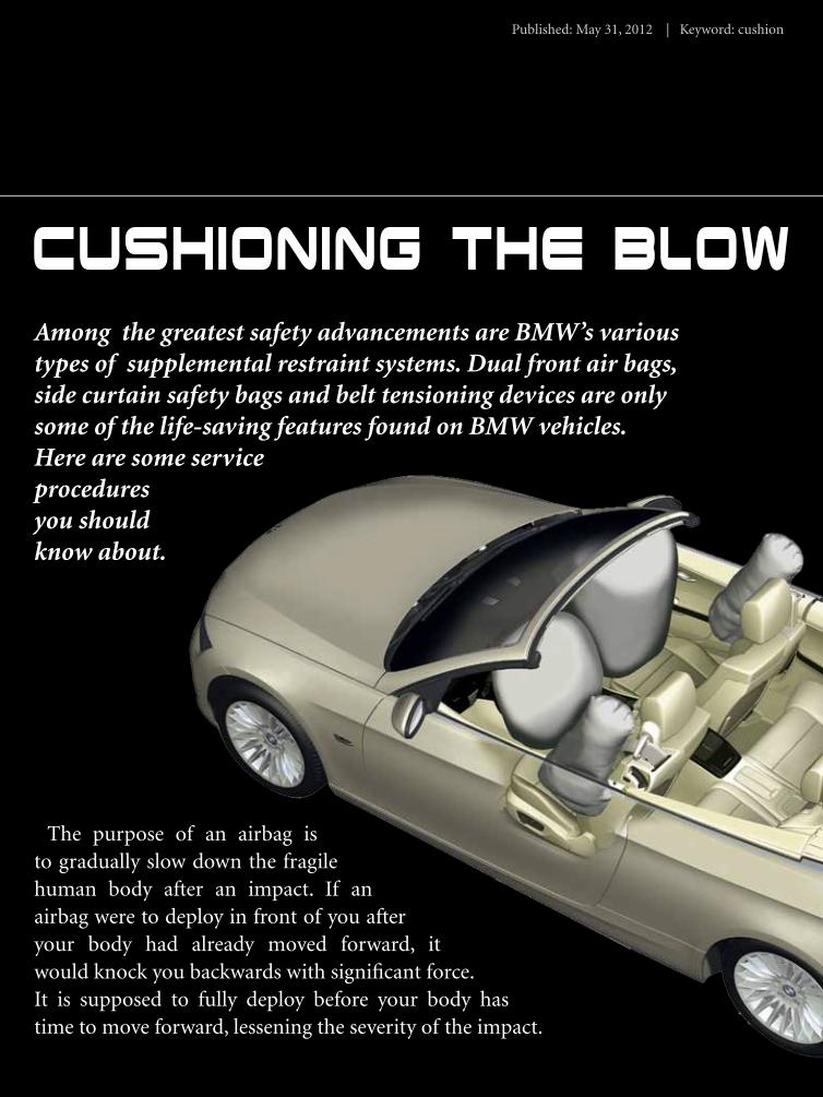
The purpose of an airbag is to gradually slow down the fragile human body after an impact. If an airbag were to deploy in front of you after your body had already moved forward, it would knock you backwards with significant force. It is supposed to fully deploy before your body has time to move forward, lessening the severity of the impact.
Among the greatest safety advancements are BMW’s various types of supplemental restraint systems. Dual front air bags, side curtain safety bags and belt tensioning devices are only some of the life-saving features found on BMW vehicles. Here are some service procedures you should know about.

Import service | www.mastertechmag.com40
Cushioning the Blow
Three-point seat and shoulder belts continue to be valuable safety devices. They keep you in the correct position to maximize the airbag’s effectiveness.
The complexities of the dynamics involved in a crash are incredible. BMW’s extensive research and development allow these restraint systems to minimize the occupants’ injuries with these carefully-designed safety systems. In addition, high-strength steel helps maintain the cabin’s shape, crumple zones absorb much of the energy of an accident, and airbags mitigate the rate of deceleration of the body. This is why, after an accident, it is so critical to return the vehicle to its original pre-crash state. It is essential that the
vehicle’s safety systems provide the same level of protection and after-collision performance as when it left the factory.
Evolution, Not Revolution
Combination seat belt/shoulder harness assemblies have been standard equipment on BMWs for decades. In 1990, BMW added seat belt pre-tensioners. In a collision, an explosive charge (a mechanical system on the 3 series) tightens the seat belts in use to further restrain the occupant’s movement inside the cabin.
Driver’s-side airbags have been around
With a paid subscription to www.bmwtechinfo.com you can access factory-level wiring diagrams. You can also retrieve component location, diagnostic information, and proper repair procedures to assist you during a repair.

May 2012 | Import service 41
since the mid-’80s. Passenger’s-side airbags have been used since the early ‘90s as well. In the mid-’90s, BMW started to implement seat-occupancy recognition systems, and the “intelligent” airbag system, also known as a dual-threshold deployment system. In less-severe collisions, or when a seat belt is not fastened, only one airbag will deploy. In a more severe crash both airbags are deployed simultaneously and offer better high-impact protection.
In 1996, door-mounted side airbags were added. These protect the occupants’ bodies in the event of a side impact. BMW did not stop there. In 1997, BMW introduced HPS, the Head Protection System. Sometimes referred to as a curtain airbag, it protects an occupant’s head in
the event of a collision. Rear side airbags were also offered as an option then.
In 1997, the innovative BST, Battery Safety Terminal, cable was also introduced. This positive battery terminal has an explosive charge in it that disconnects the battery from the rest of the vehicle during a collision. This helps reduce the possibility of an electrical spark igniting any flammable liquids or other materials that might be present during an accident.
Dual-stage airbags were introduced in 1999. Here, a sensing system evaluates the severity of an impact and determines what combination of airbags will be deployed. With these and other advancements, today BMW no longer refers to these
As you can see in this photo, the impact sensor has sustained some water damage. Water was leaking into the cabin and collected under the driver’s seat where the sensor is mounted. The impact sensor must be mounted properly in order to work correctly.

Import service | www.mastertechmag.com42
Cushioning the Blow
safety systems as airbags, SRS or SIR. They are now simply called MRS for Multiple Restraint Systems.
Roll CallWith all of this safety technology in
BMW vehicles, it is important to know the new terminology in order to understand how to repair these systems. Let us look at the latest X6 E71 chassis as an example. The main brain in charge of the multiple restraint system is the ACSM (Advanced Crash Safety Module), which receives its power from the CAS (Car Access System). This ACSM is in total control of every airbag in the system and receives sensor inputs from impact sensors placed throughout the vehicle. It processes these signals and determines which airbags should fire and in what combination.
Aside from receiving inputs from impact sensors the ACSM also has two acceleration sensors itself. One sensor is used to detect the severity of a forward or rearward collision. The other acceleration sensor detects side impacts. This is important. Since the control unit can determine what direction the impact comes from, it can manage the more advanced system features that have been added to promote occupant safety.
On this same E71 chassis, the ASCM has
When replacing deployed components, it is always best to use only new components from your BMW parts supplier. Used components can expose you to liability issues if they fail to function properly in future accidents.
a total of eight impact sensors. The two front impact sensors are mounted just outboard of the radiator on both sides of the front side of the frame. There are two door impact sensors that mount in each door near the door handle. In addition, there are sensor assemblies mounted in the B pillar on each side of the vehicle. Each of these sensor assemblies has two sensors in it. The pillar-mounted impact sensor must be replaced as an assembly, so there are six serviceable impact sensors. This gives us a total of six external sensors and one ACSM that are serviceable components.
The E71 also has a total of eight airbags. The driver’s and passenger’s airbags are both dual-stage. They will need to be replaced as assemblies. There are two knee bolster-mounted airbags to protect

May 2012 | Import service 43
A New INdustry stANdArd IN shop MANAgeMeNt softwAre.
Know your profit margins before you sell the job.Order parts electronically from your favorite vendors. E-mail estimates to your customers.Perform your own in-house marketing, or integrate
with the CRM company of your choice.Import labor times from ALLDATA·Decode VINs automatically.Never suffer another misspelling.Get the answers you need from GO’s unique reports.Connect & communicate with your PC based shop equipment.Own the software and your data.Control your business.
E m p o w E r m E n t :
Regular updates & basic support for one low monthly fee.Continuous review and refinement from IATN, GO Users Forum.Sel ected as the exclusive shop management software for the
AAIA Shop Of Tomorrow.
B r a g g i n g r i g h t s :
Visit www.garageoperator.com for more information.
www.mastertechmag.com
Call Us!800-841-7360

Import service | www.mastertechmag.com44
Cushioning the Blow
the driver’s and passenger’s knees. The two side airbags are mounted in their respective seats. Two curtain airbags for the Head Protection System (HPS) are mounted on each side of the roof just above the doors.
Airbags are not the only components activated in an accident on the new X6. There are also four front seat belt pre-tensioners. Two are mounted on each front seat belt. One is on the buckle side and the other is on the belt side mounted in the B pillar. There are also two seat belt pre-
tensioners mounted on each side of the rear seat belt buckles. What is relatively new here is the Active Head Restraint system. This deploys the headrest forward to reduce the distance between an occupant’s head and the headrest in rear-end collisions. Finally, we have the BST cable mounted on the positive terminal of the battery. This gives us a total of 17 serviceable igniting components in the MRS.
The ACSM has some additional inputs other than those from the crash sensors. The seat belt buckles have switches to indicate if they are latched. There is a switch that is discretely wired to the ACSM to turn on and off the passenger side airbags. There are also both driver’s and passenger’s side seat occupancy sensors mounted in the seat cushions. These sensors detect the approximate size of the occupants and their signals are used to calculate airbag deployment rates.
Modern BMW computer controls incorporate self-diagnostics to assist in troubleshooting, especially when dealing with airbag systems. BMW does not recommend using any electrical test equipment to test wiring or components, and strongly recommends that you use the self-diagnostic features of the BMW factory scan tool. You can use the ISTA feature on the BMW technical information website with an appropriate BMW ICOM interface, or approved passthrough
Above: When replacing any airbag component, it is very important to duplicate the existing harness routing. Here we have the pre-tensioner wiring routed between the seat cushion and the plastic cushion support. This positioning ensures that the wiring is not caught on the seat adjustment track and damaged.
May 2012 | Import service 45
device as your diagnostic tool. For more information on these procedures, take a look at www.bmwtechinfo.com “Online Service System.”
Repair Procedures
Of course, when dealing with any airbag system you should take all necessary precautions in order to prevent injury. The system should only be serviced with the key in the “0” position. The battery must be disconnected and you should wait at least a full minute before disconnecting any impact sensors or airbags from the vehicle. The BST cable kills power to the vehicle during an accident, but the ACSM has capacitors that continue to supply power to the control unit even after the battery is disconnected. This is why you must wait one minute before you start any service work on the vehicle.
Obviously, you will need to replace any deployed airbags. That is clear. What may not be clear is if the Active Head Restraint system has been deployed. Also, the seat belt pre-tensioners may need to be replaced even if the accident was not severe enough to deploy the airbags. For particular models, the means of finding out if these units must be replaced can be found at www.bmwtechinfo.com.
The ACSM is capable of recording vehicle information during a crash, similar to a “black box” in an airliner. This information can be retrieved for the purposes of an investigation or insurance claim. The unit can record and retain information for up to three accidents. After that, the memory is full and cannot be cleared so the ACSM must be replaced. The ACSM is coded specifically to each individual vehicle, so the replacement will also need to be coded.
When you are performing repair work on the vehicle, you are expected to unplug the ACSM before unplugging any additional components. Within the ACSM connector are shorting bars that bridge all of the wiring together to prevent any accidental firings. If welding is involved, you should also remove all possible ignition devices in order to prevent any accidental deployment during the repair.
Winding UpBMW’s reputation for safety is
impressive. After a collision, the BMW owner expects the vehicle to be returned to its pre-crash performance capabilities. Not just cosmetically, but also in terms of crashworthiness. It is essential that you use the proper tools, parts, and procedures to assure that all safety systems will perform as designed. These same procedures will also help prevent injury during repair.

mastertechmagwww.
.com
ONLINEO
Master Technician
Also Inside:
Tackling MRS
Sleeping Giant
Scan Tools Revisited
January 2012
Volume 6 | Issue 1
So lu t i ons fo r P ro fess iona l Au tomot i ve Repa i r Techn ic i ans
a m a s t e r t e c h m a g . c o m o n l i n e p u b l i c a t i o n
Ticking
Away
Also inside:
Gearing up for Asian Repair
Automotive Forensics
Getting Comfortable
September/October 2011 Vol.16 No.2