hardware installation sinamics - siemens · 2017-09-11 · sinamics sinamics g120 power module...
TRANSCRIPT
Hardware Installation Manual
PM240-2 Power Modules, IP20 / push-through technology (PT)
SINAMICS G120 frequency converters
08/2017Edition
SINAMICS
www.siemens.com/drives


SINAMICS
SINAMICS G120Power Module PM240-2
Hardware Installation Manual
08/2017
08/2017A5E33294624B AG
Changes in this manual 1Fundamental safety instructions 2
Introduction 3
Installing/mounting 4
Connecting-up 5
Service and maintenance 6
Technical data 7
Spare parts 8
Accessories 9
Appendix A

Legal informationWarning notice system
This manual contains notices you have to observe in order to ensure your personal safety, as well as to prevent damage to property. The notices referring to your personal safety are highlighted in the manual by a safety alert symbol, notices referring only to property damage have no safety alert symbol. These notices shown below are graded according to the degree of danger.
DANGERindicates that death or severe personal injury will result if proper precautions are not taken.
WARNINGindicates that death or severe personal injury may result if proper precautions are not taken.
CAUTIONindicates that minor personal injury can result if proper precautions are not taken.
NOTICEindicates that property damage can result if proper precautions are not taken.If more than one degree of danger is present, the warning notice representing the highest degree of danger will be used. A notice warning of injury to persons with a safety alert symbol may also include a warning relating to property damage.
Qualified PersonnelThe product/system described in this documentation may be operated only by personnel qualified for the specific task in accordance with the relevant documentation, in particular its warning notices and safety instructions. Qualified personnel are those who, based on their training and experience, are capable of identifying risks and avoiding potential hazards when working with these products/systems.
Proper use of Siemens productsNote the following:
WARNINGSiemens products may only be used for the applications described in the catalog and in the relevant technical documentation. If products and components from other manufacturers are used, these must be recommended or approved by Siemens. Proper transport, storage, installation, assembly, commissioning, operation and maintenance are required to ensure that the products operate safely and without any problems. The permissible ambient conditions must be complied with. The information in the relevant documentation must be observed.
TrademarksAll names identified by ® are registered trademarks of Siemens AG. The remaining trademarks in this publication may be trademarks whose use by third parties for their own purposes could violate the rights of the owner.
Disclaimer of LiabilityWe have reviewed the contents of this publication to ensure consistency with the hardware and software described. Since variance cannot be precluded entirely, we cannot guarantee full consistency. However, the information in this publication is reviewed regularly and any necessary corrections are included in subsequent editions.
Siemens AGDivision Digital FactoryPostfach 48 4890026 NÜRNBERGGERMANY
A5E33294624B AGⓅ 09/2017 Subject to change
Copyright © Siemens AG 2013 - 2017.All rights reserved

Table of contents
1 Changes in this manual................................................................................................................................9
2 Fundamental safety instructions.................................................................................................................11
2.1 General safety instructions.....................................................................................................11
2.2 Equipment damage due to electric fields or electrostatic discharge......................................16
2.3 Warranty and liability for application examples......................................................................17
2.4 Industrial security...................................................................................................................18
2.5 Residual risks of power drive systems...................................................................................19
3 Introduction.................................................................................................................................................21
3.1 Permissible motors.................................................................................................................22
4 Installing/mounting......................................................................................................................................23
4.1 Installation conditions.............................................................................................................23
4.2 EMC-compliant installation of a machine or system..............................................................264.2.1 Control cabinet.......................................................................................................................274.2.2 Cables....................................................................................................................................284.2.3 Electromechanical components.............................................................................................31
4.3 Power losses and air cooling requirements...........................................................................32
4.4 Mounting the Power Modules.................................................................................................334.4.1 Sequence for installing the Power Module.............................................................................344.4.2 Dimension drawings and drilling dimensions for built-in units - IP20 devices........................354.4.3 Dimension drawings and drilling dimensions for PT Power Modules.....................................374.4.4 Mounting the shield plates.....................................................................................................414.4.5 Hoisting gear FSD ... PSF......................................................................................................44
4.5 Additional components...........................................................................................................45
5 Connecting-up............................................................................................................................................47
5.1 Permissible line supplies........................................................................................................505.1.1 TN line system.......................................................................................................................505.1.2 TT line system........................................................................................................................515.1.3 IT system................................................................................................................................525.1.4 Protective conductor..............................................................................................................53
5.2 Connecting the line and motor cable at the inverter...............................................................555.2.1 Connection overview..............................................................................................................555.2.2 Length of the motor cable......................................................................................................595.2.3 Connection terminals at the inverter......................................................................................605.2.4 Establishing connections........................................................................................................61
5.3 STO via Power Module terminals...........................................................................................64
5.4 Connecting the motor to the inverter in a star or delta connection.........................................66
Power Module PM240-2Hardware Installation Manual, 08/2017, A5E33294624B AG 5

6 Service and maintenance...........................................................................................................................67
6.1 Maintenance...........................................................................................................................68
6.2 Commissioning after a long storage time...............................................................................69
6.3 Replacing a fan......................................................................................................................706.3.1 Fan replacement FSA … FSC...............................................................................................706.3.2 Fan replacement FSD … FSF................................................................................................71
7 Technical data............................................................................................................................................73
7.1 Electromagnetic compatibility - Overview .............................................................................74
7.2 Ambient conditions.................................................................................................................75
7.3 Overload capability of the inverter..........................................................................................77
7.4 Cable cross-sections and tightening torques ((PM240-2)).....................................................79
7.5 Technical data, 200 V inverters..............................................................................................807.5.1 General data, 200 V inverters................................................................................................807.5.2 Specific technical data, 200 V inverters.................................................................................827.5.3 Current derating depending on the pulse frequency, 200 V inverters....................................89
7.6 Technical data, 400 V inverters..............................................................................................907.6.1 General data, 400 V inverters................................................................................................907.6.2 Specific technical data, 400 V inverters.................................................................................927.6.3 Current derating depending on the pulse frequency, 400 V inverters..................................100
7.7 Technical data, 690 V inverters............................................................................................1017.7.1 General data, 690 V inverters..............................................................................................1017.7.2 Specific technical data, 690 V inverters...............................................................................1037.7.3 Current derating depending on the pulse frequency, 690 V inverters..................................107
7.8 Restrictions for special ambient conditions..........................................................................108
7.9 Electromagnetic compatibility of variable-speed drives.......................................................1117.9.1 Inverter applications.............................................................................................................1127.9.1.1 Operation in the Second Environment.................................................................................1127.9.1.2 Operation in the First Environment......................................................................................1147.9.2 Typical harmonic currents....................................................................................................1157.9.3 EMC limit values in South Korea..........................................................................................116
8 Spare parts...............................................................................................................................................117
9 Accessories..............................................................................................................................................119
9.1 Top shield plate - FSD … FSF.............................................................................................120
9.2 Mounting frames for PT power modules..............................................................................1219.2.1 Mounting instructions with mounting frame..........................................................................124
9.3 Mounting grips for PT Power Modules.................................................................................125
9.4 Line reactor..........................................................................................................................126
9.5 Line filter...............................................................................................................................129
9.6 Braking resistor....................................................................................................................1319.6.1 Connecting a braking resistor..............................................................................................1349.6.2 Technical data of the braking resistor..................................................................................135
Table of contents
Power Module PM240-26 Hardware Installation Manual, 08/2017, A5E33294624B AG

9.7 Connecting a motor holding brake.......................................................................................1389.7.1 Technical data of the brake relay?.......................................................................................1389.7.2 Connections and circuit diagrams........................................................................................1399.7.3 Mounting and connecting the brake relay............................................................................140
9.8 Output reactor......................................................................................................................141
9.9 Voltage limiter and du/dt filter...............................................................................................146
A Appendix...................................................................................................................................................149
A.1 Manuals and technical support............................................................................................149A.1.1 Manuals for your inverter.....................................................................................................149A.1.2 Configuring support..............................................................................................................150A.1.3 Product Support...................................................................................................................151
A.2 Disposal...............................................................................................................................152
A.3 Directives and standards......................................................................................................153
A.4 Abbreviations.......................................................................................................................155
Index.........................................................................................................................................................157
Table of contents
Power Module PM240-2Hardware Installation Manual, 08/2017, A5E33294624B AG 7

Table of contents
Power Module PM240-28 Hardware Installation Manual, 08/2017, A5E33294624B AG

Changes in this manual 1Changes with respect to Edition 01/2017
The Power Modules with push-through technology (PT Power Module), frame sizes FSD ... FSF, have been integrated.
Power Module PM240-2Hardware Installation Manual, 08/2017, A5E33294624B AG 9

Changes in this manual
Power Module PM240-210 Hardware Installation Manual, 08/2017, A5E33294624B AG

Fundamental safety instructions 22.1 General safety instructions
WARNING
Electric shock and danger to life due to other energy sources
Touching live components can result in death or severe injury.● Only work on electrical devices when you are qualified for this job. ● Always observe the country-specific safety rules.
Generally, the following six steps apply when establishing safety: 1. Prepare for disconnection. Notify all those who will be affected by the procedure.2. Isolate the drive system from the power supply and take measures to prevent it being
switched back on again.3. Wait until the discharge time specified on the warning labels has elapsed. 4. Check that there is no voltage between any of the power connections, and between any
of the power connections and the protective conductor connection.5. Check whether the existing auxiliary supply circuits are de-energized.6. Ensure that the motors cannot move.7. Identify all other dangerous energy sources, e.g. compressed air, hydraulic systems, or
water. Switch the energy sources to a safe state.8. Check that the correct drive system is completely locked.
After you have completed the work, restore the operational readiness in the inverse sequence.
WARNING
Electric shock due to connection to an unsuitable power supply
When equipment is connected to an unsuitable power supply, exposed components may carry a hazardous voltage that might result in serious injury or death.● Only use power supplies that provide SELV (Safety Extra Low Voltage) or PELV-
(Protective Extra Low Voltage) output voltages for all connections and terminals of the electronics modules.
Power Module PM240-2Hardware Installation Manual, 08/2017, A5E33294624B AG 11
WARNING
Electric shock due to equipment damage
Improper handling may cause damage to equipment. For damaged devices, hazardous voltages can be present at the enclosure or at exposed components; if touched, this can result in death or severe injury. ● Ensure compliance with the limit values specified in the technical data during transport,
storage and operation. ● Do not use any damaged devices.
WARNING
Electric shock due to unconnected cable shield
Hazardous touch voltages can occur through capacitive cross-coupling due to unconnected cable shields.● As a minimum, connect cable shields and the conductors of power cables that are not
used (e.g. brake cores) at one end at the grounded housing potential.
WARNING
Electric shock if there is no ground connection
For missing or incorrectly implemented protective conductor connection for devices with protection class I, high voltages can be present at open, exposed parts, which when touched, can result in death or severe injury.● Ground the device in compliance with the applicable regulations.
WARNING
Arcing when a plug connection is opened during operation
Opening a plug connection when a system is operation can result in arcing that may cause serious injury or death.● Only open plug connections when the equipment is in a voltage-free state, unless it has
been explicitly stated that they can be opened in operation.
WARNING
Electric shock due to residual charges in power components
Because of the capacitors, a hazardous voltage is present for up to 5 minutes after the power supply has been switched off. Contact with live parts can result in death or serious injury.● Wait for 5 minutes before you check that the unit really is in a no-voltage condition and
start work.
Fundamental safety instructions2.1 General safety instructions
Power Module PM240-212 Hardware Installation Manual, 08/2017, A5E33294624B AG
NOTICE
Property damage due to loose power connections
Insufficient tightening torques or vibration can result in loose power connections. This can result in damage due to fire, device defects or malfunctions.● Tighten all power connections to the prescribed torque.● Check all power connections at regular intervals, particularly after equipment has been
transported.
WARNING
Spread of fire from built-in devices
In the event of fire outbreak, the enclosures of built-in devices cannot prevent the escape of fire and smoke. This can result in serious personal injury or property damage. ● Install built-in units in a suitable metal cabinet in such a way that personnel are protected
against fire and smoke, or take other appropriate measures to protect personnel.● Ensure that smoke can only escape via controlled and monitored paths.
WARNING
Failure of pacemakers or implant malfunctions due to electromagnetic fields
Electromagnetic fields (EMF) are generated by the operation of electrical power equipment, such as transformers, converters, or motors. People with pacemakers or implants in the immediate vicinity of this equipment are at particular risk.● If you have a heart pacemaker or implant, maintain a minimum distance of 2 m from
electrical power equipment.
WARNING
Unexpected movement of machines caused by radio devices or mobile phones
When radio devices or mobile phones with a transmission power > 1 W are used in the immediate vicinity of components, they may cause the equipment to malfunction. Malfunctions may impair the functional safety of machines and can therefore put people in danger or lead to property damage.● If you come closer than around 2 m to such components, switch off any radios or mobile
phones.● Use the "SIEMENS Industry Online Support App" only on equipment that has already been
switched off.
Fundamental safety instructions2.1 General safety instructions
Power Module PM240-2Hardware Installation Manual, 08/2017, A5E33294624B AG 13

WARNING
Motor fire in the event of insulation overload
There is higher stress on the motor insulation through a ground fault in an IT system. If the insulation fails, it is possible that death or severe injury can occur as a result of smoke and fire.● Use a monitoring device that signals an insulation fault. ● Correct the fault as quickly as possible so the motor insulation is not overloaded.
WARNING
Fire due to inadequate ventilation clearances
Inadequate ventilation clearances can cause overheating of components with subsequent fire and smoke. This can cause severe injury or even death. This can also result in increased downtime and reduced service lives for devices/systems. ● Ensure compliance with the specified minimum clearance as ventilation clearance for the
respective component.
WARNING
Unrecognized dangers due to missing or illegible warning labels
Dangers might not be recognized if warning labels are missing or illegible. Unrecognized dangers may cause accidents resulting in serious injury or death.● Check that the warning labels are complete based on the documentation.● Attach any missing warning labels to the components, where necessary in the national
language.● Replace illegible warning labels.
NOTICE
Device damage caused by incorrect voltage/insulation tests
Incorrect voltage/insulation tests can damage the device.● Before carrying out a voltage/insulation check of the system/machine, disconnect the
devices as all converters and motors have been subject to a high voltage test by the manufacturer, and therefore it is not necessary to perform an additional test within the system/machine.
Fundamental safety instructions2.1 General safety instructions
Power Module PM240-214 Hardware Installation Manual, 08/2017, A5E33294624B AG

WARNING
Unexpected movement of machines caused by inactive safety functions
Inactive or non-adapted safety functions can trigger unexpected machine movements that may result in serious injury or death. ● Observe the information in the appropriate product documentation before commissioning.● Carry out a safety inspection for functions relevant to safety on the entire system, including
all safety-related components.● Ensure that the safety functions used in your drives and automation tasks are adjusted
and activated through appropriate parameterizing. ● Perform a function test.● Only put your plant into live operation once you have guaranteed that the functions relevant
to safety are running correctly.
NoteImportant safety notices for Safety Integrated functions
If you want to use Safety Integrated functions, you must observe the safety notices in the Safety Integrated manuals.
Fundamental safety instructions2.1 General safety instructions
Power Module PM240-2Hardware Installation Manual, 08/2017, A5E33294624B AG 15

2.2 Equipment damage due to electric fields or electrostatic dischargeElectrostatic sensitive devices (ESD) are individual components, integrated circuits, modules or devices that may be damaged by either electric fields or electrostatic discharge.
NOTICE
Equipment damage due to electric fields or electrostatic discharge
Electric fields or electrostatic discharge can cause malfunctions through damaged individual components, integrated circuits, modules or devices.● Only pack, store, transport and send electronic components, modules or devices in their
original packaging or in other suitable materials, e.g conductive foam rubber of aluminum foil.
● Only touch components, modules and devices when you are grounded by one of the following methods:– Wearing an ESD wrist strap– Wearing ESD shoes or ESD grounding straps in ESD areas with conductive flooring
● Only place electronic components, modules or devices on conductive surfaces (table with ESD surface, conductive ESD foam, ESD packaging, ESD transport container).
Fundamental safety instructions2.2 Equipment damage due to electric fields or electrostatic discharge
Power Module PM240-216 Hardware Installation Manual, 08/2017, A5E33294624B AG

2.3 Warranty and liability for application examplesThe application examples are not binding and do not claim to be complete regarding configuration, equipment or any eventuality which may arise. The application examples do not represent specific customer solutions, but are only intended to provide support for typical tasks. You are responsible for the proper operation of the described products. These application examples do not relieve you of your responsibility for safe handling when using, installing, operating and maintaining the equipment.
Fundamental safety instructions2.3 Warranty and liability for application examples
Power Module PM240-2Hardware Installation Manual, 08/2017, A5E33294624B AG 17

2.4 Industrial security
NoteIndustrial security
Siemens provides products and solutions with industrial security functions that support the secure operation of plants, systems, machines and networks.
In order to protect plants, systems, machines and networks against cyber threats, it is necessary to implement – and continuously maintain – a holistic, state-of-the-art industrial security concept. Siemens products and solutions only represent one component of such a concept.
The customer is responsible for preventing unauthorized access to its plants, systems, machines and networks. Systems, machines and components should only be connected to the enterprise network or the internet if and to the extent necessary and with appropriate security measures (e.g. use of firewalls and network segmentation) in place.
Additionally, Siemens’ guidance on appropriate security measures should be taken into account. For more information about industrial security, please visit:
Industrial security (http://www.siemens.com/industrialsecurity).
Siemens’ products and solutions undergo continuous development to make them more secure. Siemens strongly recommends to apply product updates as soon as available and to always use the latest product versions. Use of product versions that are no longer supported, and failure to apply latest updates may increase customer’s exposure to cyber threats.
To stay informed about product updates, subscribe to the Siemens Industrial Security RSS Feed at:
Industrial security (http://www.siemens.com/industrialsecurity).
WARNING
Unsafe operating states resulting from software manipulation
Software manipulations (e.g. viruses, trojans, malware or worms) can cause unsafe operating states in your system that may lead to death, serious injury, and property damage.● Keep the software up to date. ● Incorporate the automation and drive components into a holistic, state-of-the-art industrial
security concept for the installation or machine.● Make sure that you include all installed products into the holistic industrial security concept.● Protect files stored on exchangeable storage media from malicious software by with
suitable protection measures, e.g. virus scanners.
Fundamental safety instructions2.4 Industrial security
Power Module PM240-218 Hardware Installation Manual, 08/2017, A5E33294624B AG

2.5 Residual risks of power drive systemsWhen assessing the machine- or system-related risk in accordance with the respective local regulations (e.g., EC Machinery Directive), the machine manufacturer or system installer must take into account the following residual risks emanating from the control and drive components of a drive system:
1. Unintentional movements of driven machine or system components during commissioning, operation, maintenance, and repairs caused by, for example,
– Hardware and/or software errors in the sensors, control system, actuators, and cables and connections
– Response times of the control system and of the drive
– Operation and/or environmental conditions outside the specification
– Condensation/conductive contamination
– Parameterization, programming, cabling, and installation errors
– Use of wireless devices/mobile phones in the immediate vicinity of electronic components
– External influences/damage
– X-ray, ionizing radiation and cosmic radiation
2. Unusually high temperatures, including open flames, as well as emissions of light, noise, particles, gases, etc., can occur inside and outside the components under fault conditions caused by, for example:
– Component failure
– Software errors
– Operation and/or environmental conditions outside the specification
– External influences/damage
3. Hazardous shock voltages caused by, for example:
– Component failure
– Influence during electrostatic charging
– Induction of voltages in moving motors
– Operation and/or environmental conditions outside the specification
– Condensation/conductive contamination
– External influences/damage
4. Electrical, magnetic and electromagnetic fields generated in operation that can pose a risk to people with a pacemaker, implants or metal replacement joints, etc., if they are too close
5. Release of environmental pollutants or emissions as a result of improper operation of the system and/or failure to dispose of components safely and correctly
6. Influence of network-connected communication systems, e.g. ripple-control transmitters or data communication via the network
For more information about the residual risks of the drive system components, see the relevant sections in the technical user documentation.
Fundamental safety instructions2.5 Residual risks of power drive systems
Power Module PM240-2Hardware Installation Manual, 08/2017, A5E33294624B AG 19

Fundamental safety instructions2.5 Residual risks of power drive systems
Power Module PM240-220 Hardware Installation Manual, 08/2017, A5E33294624B AG

Introduction 3Overview
The Power Modules belong to the modular family of SINAMICS G120 inverters. A modular inverter comprises Control Unit and Power Module.
Depending on the power rating in frame sizes FSA … FSF, the following Power Module versions are supplied:
● 1 AC 200 V 0.55 kW … 4 kW for line voltages from 1 AC 200 V … 240 V● 3 AC 200 V 0.55 kW … 55 kW for line voltages from 3 AC 200 V … 240 V● 3 AC 400 V 0.55 kW … 132 kW for line voltages from 3 AC 380 V … 480 V● 3 AC 690 V 11 kW … 132 kW for line voltages from 3 AC 500 V … 690 V
Control Units for the Power ModulesYou can operate the Power Modules with a Control Unit from one of the following listed families.
● CU230P-2
● CU240B-2
● CU240E-2
● CU250S-2
For Power Modules FSA … FSC, you require a Control Unit with firmware version V4.4 or higher.
For Power Modules FSD … FSF, you require a Control Unit with firmware version V4.7 HF8 or higher.
NoteCommissioning the inverter
You must first commission the inverter before you can use it. Commissioning is described in the Operating Instructions of the relevant Control Unit.
Manuals for your inverter (Page 149)
STO independent of the Control UnitUsing the PM240-2 Power Modules, frame sizes FSD, FSE and FSF, you can implement the "Safe Torque Off" safety function (STO), corresponding to PL e according to EN 13849-1 and SIL 3 according to IEC61508.
STO via Power Module terminals (Page 64).
Power Module PM240-2Hardware Installation Manual, 08/2017, A5E33294624B AG 21

3.1 Permissible motors
NoteMotors for inverter operation
Only use motors that are suitable for operation with inverters with a DC link.
Motors for 200 V Power ModulesFor the 200 V Power Modules, induction motors are permissible in the range from 25% … 150% of the inverter power without any restrictions.
Motors for 400 V Power ModulesFor the 400 V Power Modules, induction motors are permissible in the range from 25 % … 150 % of the inverter power without any restrictions.
Motors for 690 V Power ModulesFor the 690 V Power Modules, induction motors are permissible in the range from 50 % … 150 % of the inverter power without any restrictions.
Introduction3.1 Permissible motors
Power Module PM240-222 Hardware Installation Manual, 08/2017, A5E33294624B AG

Installing/mounting 44.1 Installation conditions
General installation conditionsWhen installing the Power Modules carefully observe the conditions listed below in order to guarantee reliable, continuous and disturbance-free operation.
● The Power Modules are designed for installation in a control cabinet.
● The Power Modules are certified for use in environments with degree of pollution 2 without condensation; i.e. in environments where no conductive pollution/dirt occurs.
● The built-in units fulfill IP20 degree of protection.
● You can find the permissible conductor cross-sections for the terminals in: Connection terminals at the inverter (Page 60)
● The following section describes how you can install the Power Module in compliance with EMC regulations:
EMC-compliant installation of a machine or system (Page 26)
● Devices in push-through technology – PT devices
– PT devices have IP20 degree of protection and at the rear of the control cabinet they fulfil IP55.
– PT devices, FSF: A pressure compensation valve is necessary for the cabinet in order to prevent underpressure in the cabinet.
Inverters for systems in the United States / Canada (UL/cUL)● For a system configuration in conformance with UL/cUL, use the fuse types approved for
UL/cUL, specified in the Technical data, or the circuit breakers under the following Internet address.
– Fuse types: Technical data (Page 73)
– Circuit breaker (https://support.industry.siemens.com/cs/ww/en/view/109486009)
● The integrated semiconductor short-circuit protection does not provide cable protection.
● On the system side, provide cable protection in conformance with NEC or CEC, Part 1 and the local regulations.
● The inverters provide internal motor protection corresponding to UL61800-5-1. The protection threshold is 115 % of the inverter full load current. When commissioning, you can adapt the motor overload protection using parameter p0640.
● For frame size FSF, to connect the line supply and motor only use UL approved ring-type cable lugs (ZMVV), which are certified for the particular voltage, with a permissible current of at least 125 % of the input and output current. Use the higher value as basis.
Power Module PM240-2Hardware Installation Manual, 08/2017, A5E33294624B AG 23

Installing/mounting 4.1 Installation conditions
Power Module PM240-2 24 Hardware Installation Manual, 08/2017, A5E33294624B AG
● Carefully note that for plants and systems in conformance with UL/cUL, the line and output voltage may not be higher than 600 V.
● Only use copper cables rated for 60 °C or 75 °C.
● FSE, IP20: Only use cables that are certified for temperatures of 75 °C to connect the braking resistor.
● FSE, PT: Only use cables that are certified for temperatures of 75 °C to connect the line supply, motor and braking resistor.
● The inverters are Open Type devices.
● The push-through FSD ... FSF inverters are Open Type devices. At the rear of the control cabinet they fulfil Enclosure Type 1.
● The DC-link terminals, DCP and DCN, were not investigated regarding conformance with UL/cUL.
Additional requirements for CSA compliance, frame sizes FSA … FSC Install the inverter with an external suppression device with the following properties:
● Surge protection device with the appropriate certification (category checking numbers VZCA and VZCA7)
● Rated supply voltage
– 240 V (phase with respect to ground), 240 V (phase to phase) for 200 V inverters
– 480 V (phase to phase) for 400 V inverters
● Terminal voltage, VPR
– max. 2000 V for 200 V inverters
– max. 2500 V for 400 V inverters
● Overvoltage category III
● Pollution degree 2
● Suitable for SPD applications, type 1 or type 2
Alternatively, use a surge protection device, article number 5SD7 424-1 from Siemens AG.

Installing/mounting 4.1 Installation conditions
Power Module PM240-2 Hardware Installation Manual, 08/2017, A5E33294624B AG 25
Additional requirements relating to CSA conformance, frame sizes FSD … FSF Overvoltage category OVC III must be ensured for all connections of the power circuit. This can mean that a surge suppressor must connected upstream on the line side. The rated voltage of the surge suppressor must not exceed the line voltage, and must guarantee the limit values (VPR) specified here. Line voltage Phase to ground Phase to phase
Rated voltage
VPR Rated voltage
VPR
3 AC 200 V … 240 V Grounded neutral conductor 139 V 2.5 kV 240 V 4 kV Grounded line conductor 240 V 4 kV 240 V 4 kV
3 AC 380 V … 480 V Grounded neutral conductor 277 V 4 kV 480 V 4 kV Grounded line conductor 480 V 6 kV 480 V 4 kV
3 AC 500 V … 600 V Grounded neutral conductor 347 V 6 kV 600 V 4 kV Grounded line conductor 600 V 6 kV 600 V 4 kV

4.2 EMC-compliant installation of a machine or systemThe inverter is designed for operation in industrial environments where strong electromagnetic fields are to be expected.
Reliable and disturbance-free operation is only guaranteed for EMC-compliant installation.
To achieve this, subdivide the control cabinet and the machine or system into EMC zones:
EMC zones
Figure 4-1 Example of the EMC zones of a plant or machine
Inside the control cabinet● Zone A: Line supply connection
● Zone B: Power electronicsDevices in Zone B generate energy-rich electromagnetic fields.
● Zone C: Control and sensorsDevices in Zone C do not generate any energy-rich electromagnetic fields themselves, but their functions can be impaired by electromagnetic fields.
Outside the control cabinet● Zone D: Motors, braking resistors
Devices in Zone D generate electromagnetic fields with a significant amount of energy
Installing/mounting4.2 EMC-compliant installation of a machine or system
Power Module PM240-226 Hardware Installation Manual, 08/2017, A5E33294624B AG
4.2.1 Control cabinet● Assign the various devices to zones in the control cabinet.
● Electromagnetically uncouple the zones from each other by means of one of the following actions:
– Side clearance ≥ 25 cm
– Separate metal enclosure
– Large-area partition plates
● Route cables of various zones in separate cable harnesses or cable ducts.
● Install filters or isolation amplifiers at the interfaces of the zones.
Control cabinet assembly● Connect the door, side panels, top and base plate of the control cabinet with the control
cabinet frame using one of the following methods:
– Electrical contact surface of several cm² for each contact location
– Several screw connections
– Short, finely stranded, braided copper wires with cross-sections ≥ 95 mm² / 000 (3/0) (‑2) AWG
● Install a shield support for shielded cables that are routed out of the control cabinet.
● Connect the PE bar and the shield support to the control cabinet frame through a large surface area to establish a good electrical connection.
● Mount the control cabinet components on a bare metal mounting plate.
● Connect the mounting plate to the control cabinet frame and PE bar and shield support through a large surface area to establish a good electrical connection.
● For screw connections onto painted or anodized surfaces, establish a good conductive contact using one of the following methods:
– Use special (serrated) contact washers that cut through the painted or anodized surface.
– Remove the insulating coating at the contact locations.
Measures required for several control cabinets● Install equipotential bonding for all control cabinets.
● Screw the frames of the control cabinets together at several locations through a large surface area using serrated washers to establish a good electrical connection.
● In plants and systems where the control cabinets are lined up next to one another, and which are installed in two groups back to back, connect the PE bars of the two cabinet groups at as many locations as possible.
Installing/mounting4.2 EMC-compliant installation of a machine or system
Power Module PM240-2Hardware Installation Manual, 08/2017, A5E33294624B AG 27

Figure 4-2 Grounding and high-frequency equipotential bonding measures in the control cabinet and in the plant/system
Further informationAdditional information about EMC-compliant installation is available in the Internet:
EMC installation guideline (https://support.industry.siemens.com/cs/ww/de/view/60612658/en)
4.2.2 CablesCables with a high level of interference and cables with a low level of interference are connected to the inverter:
● Cables with a high level of interference:
– Cable between the line filter and inverter
– Motor cable
– Cable at the inverter DC link connection
– Cable between the inverter and braking resistor
● Cables with a low level of interference:
– Cable between the line and line filter
– Signal and data cables
Installing/mounting4.2 EMC-compliant installation of a machine or system
Power Module PM240-228 Hardware Installation Manual, 08/2017, A5E33294624B AG

Cable routing inside the cabinet● Route the power cables with a high level of interference so that there is a minimum
clearance of 25 cm to cables with a low level of interference.If the minimum clearance of 25 cm is not possible, insert separating metal sheets between the cables with a high level of interference and cables with a low level of interference. Connect these separating metal sheets to the mounting plate to establish a good electrical connection.
● Cables with a high level of interference and cables with a low level of interference may only cross over at right angles:
● Keep all of the cables as short as possible.
● Route all of the cables close to the mounting plates or cabinet frames.
● Route signal and data cables - as well as the associated equipotential bonding cables - parallel and close to one another.
● Twist incoming and outgoing unshielded individual conductors.Alternatively, you can route incoming and outgoing conductors in parallel, but close to one another.
● Ground any unused conductors of signal and data cables at both ends.
● Signal and data cables must only enter the cabinet from one side, e.g. from below.
● Using shielded cables for the following connections:
– Cable between the inverter and line filter
– Cable between the inverter and output reactor or sine-wave filter
Figure 4-3 Routing inverter cables inside and outside a control cabinet
Installing/mounting4.2 EMC-compliant installation of a machine or system
Power Module PM240-2Hardware Installation Manual, 08/2017, A5E33294624B AG 29
Routing cables outside the control cabinet● Maintain a minimum clearance of 25 cm between cables with a high level of interference
and cables with a low level of interference.
● Using shielded cables for the following connections:
– Inverter motor cable
– Cable between the inverter and braking resistor
– Signal and data cables
● Connect the motor cable shield to the motor enclosure using a PG gland that establishes a good electrical connection.
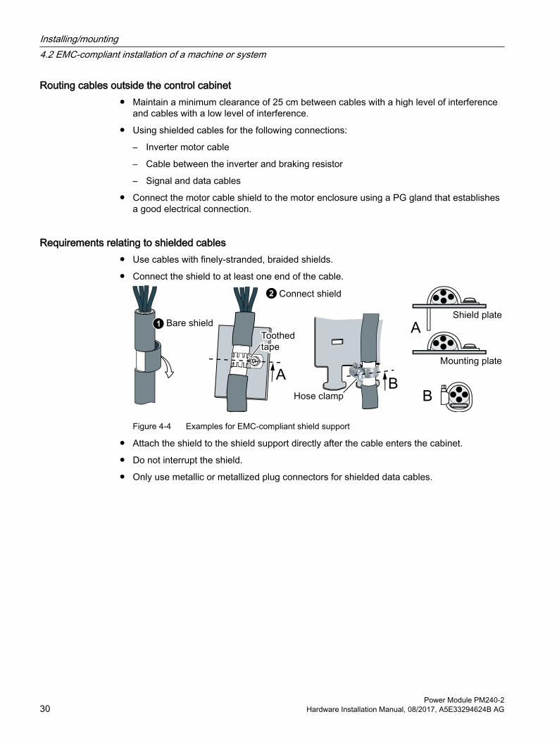
Requirements relating to shielded cables● Use cables with finely-stranded, braided shields.
● Connect the shield to at least one end of the cable.
Figure 4-4 Examples for EMC-compliant shield support
● Attach the shield to the shield support directly after the cable enters the cabinet.
● Do not interrupt the shield.
● Only use metallic or metallized plug connectors for shielded data cables.
Installing/mounting4.2 EMC-compliant installation of a machine or system
Power Module PM240-230 Hardware Installation Manual, 08/2017, A5E33294624B AG

4.2.3 Electromechanical components
Surge voltage protection circuit● Connect surge voltage protection circuits to the following components:
– Coils of contactors
– Relays
– Solenoid valves
– Motor holding brakes
● Connect the surge voltage protection circuit directly at the coil.
● Use RC elements or varistors for AC-operated coils and freewheeling diodes or varistors for DC-operated coils.
Installing/mounting4.2 EMC-compliant installation of a machine or system
Power Module PM240-2Hardware Installation Manual, 08/2017, A5E33294624B AG 31

4.3 Power losses and air cooling requirements
Cooling requirements To protect the components from overheating, the control cabinet requires a cooling air flow, which depends on the power loss of the individual components.
Formula for calculating the cooling airflow:
airflow [l/s] = power loss [W] * 0.86 / ΔT [K]
● Power loss: Total of the power losses of the individual components.
● Δ T: Permissible temperature rise in the control cabinet
Measures in order to ensure that the components are adequately cooled
● Add the power losses of the individual components.– Power Module data:
"Technical data (Page 73)". – The Control Unit power loss is
less than 0.04 kW.– Use the manufacturers data for
components, for example reactors or filters
● Calculate the air flow required, using the formula above.
● Ensure that the control cabinet is appropriately ventilated and equipped with suitable air filters.
● Ensure that the components maintain the specified clearances with respect to one another.
● Ensure that the components are provided with adequate cooling air through the cooling openings.
● Use the appropriate air barriers to prevent cooling air short circuits
Power loss for Power Modules with push-through technology - PT devicesWhen you use PT Power Modules, the majority of the power loss is dissipated through the heatsink located outside the control cabinet.
Installing/mounting4.3 Power losses and air cooling requirements
Power Module PM240-232 Hardware Installation Manual, 08/2017, A5E33294624B AG

4.4 Mounting the Power ModulesTake note of the following listed specifications when installing the Power Module.
Protection against the spread of fireThe device may be operated only in closed housings or in control cabinets with protective covers that are closed, and when all of the protective devices are used. The installation of the device in a metal control cabinet or the protection with another equivalent measure must prevent the spread of fire and emissions outside the control cabinet.
Protection against condensation or electrically conductive contaminationProtect the device, e.g. by installing it in a control cabinet with degree of protection IP54 according to IEC 60529 or NEMA 12. Further measures may be necessary for particularly critical operating conditions.
If condensation or conductive pollution can be excluded at the installation site, a lower degree of control cabinet protection may be permitted.
Installing
NOTICE
Damage caused by overheating as a result of an inadmissible mounting position
When incorrectly mounted, the Power Module can overheat and therefore be damaged.● Only install the Power Module in a vertical position with the motor connectors at the bottom.
● Maintain the minimum clearances to other components.
● Use the specified installation parts and components.
● Comply with the specified torques.
Installing/mounting4.4 Mounting the Power Modules
Power Module PM240-2Hardware Installation Manual, 08/2017, A5E33294624B AG 33
4.4.1 Sequence for installing the Power ModuleDuring installation, comply with the sequence listed below.
Frame sizes FSA ... FSC1. Prepare the cabinet.
2. Mount the shield plates.
3. Install the Power Module.
4. If you are using a Brake Relay or Safe Brake Relay:Install the Brake Relay next to the inverter.
Frame sizes FSD … FSF1. Prepare the cabinet.
2. If you are using a Brake Relay or Safe Brake Relay:Install the Brake Relay on the rear side of the shield plate.
3. Mount the shield plates.
4. Install the Power Module.
Installing/mounting4.4 Mounting the Power Modules
Power Module PM240-234 Hardware Installation Manual, 08/2017, A5E33294624B AG

4.4.2 Dimension drawings and drilling dimensions for built-in units - IP20 devicesThe following dimension drawings and drilling patterns are not to scale.
Frame sizes FSA ... FSC
Table 4-1 Dimensions depend on the Control Unit (CU) and HMI device [mm]
Frame size
Width [mm]
Height [mm] Depth [mm]without shield plate
with shield plate
without CU
with CU230P-2
with CU240B-2/CU240E-2
with CU250S-2
with‐out OP
with OP 1)
with‐out OP
with OP 1)
with‐out OP
with OP 1)
FSA 73 196 276 165 224 235 206 217 227 238FSB 100 292 370 165 224 235 206 217 227 238FSC 140 355 432 165 224 235 206 217 227 238
1) With blanking cover or with HMI device BOP-2 or IOP-2
Table 4-2 Drilling dimensions, cooling clearances and fixing
Frame size
Drilling dimensions [mm] Cooling air clearances [mm] 1) Fixing/torque [Nm]h b c Top Bottom Front
FSA 186 62.3 6 80 100 100 3 x M4 / 2.5FSB 281 80 6 80 100 100 4 x M4 / 2.5FSC 343 120 6 80 100 100 4 x M5 / 3.5
1) The Power Module is designed for mounting without any lateral cooling air clearance. For tolerance reasons, we recommend a lateral clearance of approx. 1 mm.
Installing/mounting4.4 Mounting the Power Modules
Power Module PM240-2Hardware Installation Manual, 08/2017, A5E33294624B AG 35
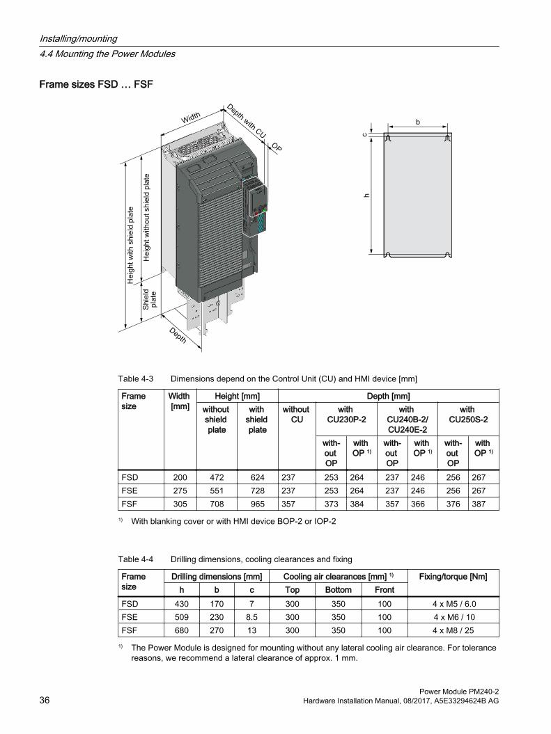
Frame sizes FSD … FSF
Table 4-3 Dimensions depend on the Control Unit (CU) and HMI device [mm]
Frame size
Width [mm]
Height [mm] Depth [mm]without shield plate
with shield plate
without CU
with CU230P-2
with CU240B-2/CU240E-2
with CU250S-2
with‐out OP
with OP 1)
with‐out OP
with OP 1)
with‐out OP
with OP 1)
FSD 200 472 624 237 253 264 237 246 256 267FSE 275 551 728 237 253 264 237 246 256 267FSF 305 708 965 357 373 384 357 366 376 387
1) With blanking cover or with HMI device BOP-2 or IOP-2
Table 4-4 Drilling dimensions, cooling clearances and fixing
Frame size
Drilling dimensions [mm] Cooling air clearances [mm] 1) Fixing/torque [Nm]h b c Top Bottom Front
FSD 430 170 7 300 350 100 4 x M5 / 6.0FSE 509 230 8.5 300 350 100 4 x M6 / 10FSF 680 270 13 300 350 100 4 x M8 / 25
1) The Power Module is designed for mounting without any lateral cooling air clearance. For tolerance reasons, we recommend a lateral clearance of approx. 1 mm.
Installing/mounting4.4 Mounting the Power Modules
Power Module PM240-236 Hardware Installation Manual, 08/2017, A5E33294624B AG

4.4.3 Dimension drawings and drilling dimensions for PT Power ModulesUse the optional mounting frame to mount a Power Module in push-through technology in a control cabinet. The mounting frame includes the necessary seals and frame to ensure compliance with degree of protection IP55.
If you do not use the optional mounting frame, then you must ensure that the required degree of protection is complied with using other appropriate measures. Mounting instructions are provided in the following section:
Mounting frames for PT power modules (Page 121)
The following dimension drawings and drilling patterns are not to scale.
Frame sizes FSA ... FSCWall thickness of the control cabinet ≤3.5 mm
Figure 4-5 Dimension drawing and drilling dimensions for frame sizes FSA ... FSC
Installing/mounting4.4 Mounting the Power Modules
Power Module PM240-2Hardware Installation Manual, 08/2017, A5E33294624B AG 37

Table 4-5 Dimensions depend on the Control Unit (CU) and HMI device [mm]
Frame size
Width [mm]
Height [mm] Overall depth in the cabinet [mm]without shield plate
with shield plate
T1 with CU230P-2
with CU240B-2/CU240E-2
with CU250S-2
with‐out OP
with OP 1)
with‐out OP
with OP 1)
with‐out OP
with OP 1)
FSA 126 238 322 118 177 188 159 170 180 191FSB 154 345 430 118 177 188 159 170 180 191FSC 200 411 500 118 177 188 159 170 180 191
1) With blanking cover or with HMI device BOP-2 or IOP-2
Table 4-6 Cooling air clearances and additional dimensions
Frame size
Power Module depth [mm] Cooling air clearances [mm] 1)
T1 + T2 T1 T2 Top Bottom FrontFSA … FSC
171 118 53 80 100 100
1) The Power Module is designed for mounting without any lateral cooling air clearance. For tolerance reasons, we recommend a lateral clearance of 1 mm.
Table 4-7 Electrical cabinet cutout and mounting
Frame size
Control cabinet cutout [mm] Fixing/torque [Nm]a b c d e
FSA 103 106 27 198 88 8 × M5 / 3.5FSB 148 134 34.5 304 116 8 × M5 / 3.5FSC 123 174 30.5 365 156 10 × M5 / 3.5
Installing/mounting4.4 Mounting the Power Modules
Power Module PM240-238 Hardware Installation Manual, 08/2017, A5E33294624B AG
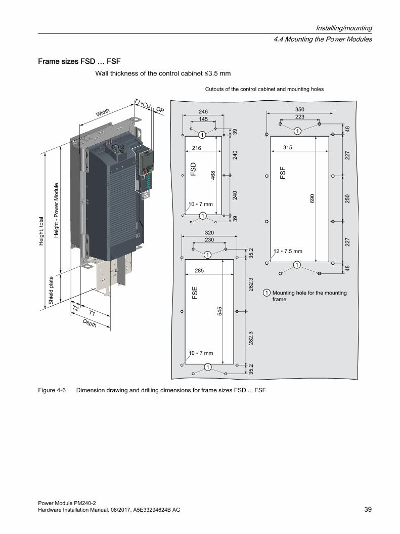
Frame sizes FSD … FSFWall thickness of the control cabinet ≤3.5 mm
Figure 4-6 Dimension drawing and drilling dimensions for frame sizes FSD ... FSF
Installing/mounting4.4 Mounting the Power Modules
Power Module PM240-2Hardware Installation Manual, 08/2017, A5E33294624B AG 39

Table 4-8 Dimensions depend on the Control Unit (CU) and HMI device [mm]
Frame size
Width [mm]
Height [mm] Overall depth in the cabinet [mm]without shield plate
with shield plate
T1 with CU230P-2
with CU240B-2/CU240E-2
with CU250S-2
with‐out OP
with OP 1)
with‐out OP
with OP 1)
with‐out OP
with OP 1)
FSD 275 517 650 141 155 166 141 148 158 169FSE 354 615 772 141 155 166 141 148 158 169FSF 384 785 1021 177.5 193 204 177.5 186 196 207
1) With blanking cover or with HMI device BOP-2 or IOP-2
Table 4-9 Cooling air clearances, further dimensions and mounting
Frame size
Power Module depth [mm] Cooling air clearances [mm] Fixing/torque [Nm]T1 + T2 T1 T2 Top Bottom Front
FSD 238.5 141 97.5 350 350 29 10 × M5 / 3.5FSD 238.5 141 97.5 350 350 29 10 × M5 / 3.5FSF 358 177.5 180.5 80 100 100 12 × M6 / 5.9
Installing/mounting4.4 Mounting the Power Modules
Power Module PM240-240 Hardware Installation Manual, 08/2017, A5E33294624B AG

4.4.4 Mounting the shield platesThe shield plates and fixings screws are included in the inverter accessory kit.
Use the provided shield plate for strain relief of the line and motor cable – as well as the shield support for the motor cable.
Mounting the shield plate, FSA ... FSC - Built-in devices
Mounting the shield plate, FSA ... FSC - PT Power Module
Installing/mounting4.4 Mounting the Power Modules
Power Module PM240-2Hardware Installation Manual, 08/2017, A5E33294624B AG 41
Mounting the shield plate and EMC connecting bracket, FSD … FSF
NoteBuilt-in devices and PT Power Modules
For frame sizes FSD ... FSF, the mounting of the shield plates is identical.EMC connecting bracket
The EMC connecting bracket is only required on inverters with integrated line filter. On inverters without a filter, the EMC connecting bracket is therefore not included in the scope of supply of the inverter.Brake Relay
If you are using a Brake Relay to control a motor brake, then mount the Brake Relay at the rear of the lower shield plate before you attach the shield module to the inverter.
Mounting and connecting the brake relay (Page 140)
If you are using an inverter with integrated line filter, then mount the shield plate and EMC connecting bracket as described below.
If you are using an inverter without filter, attach the shield plate without the EMC connecting bracket to the inverter.
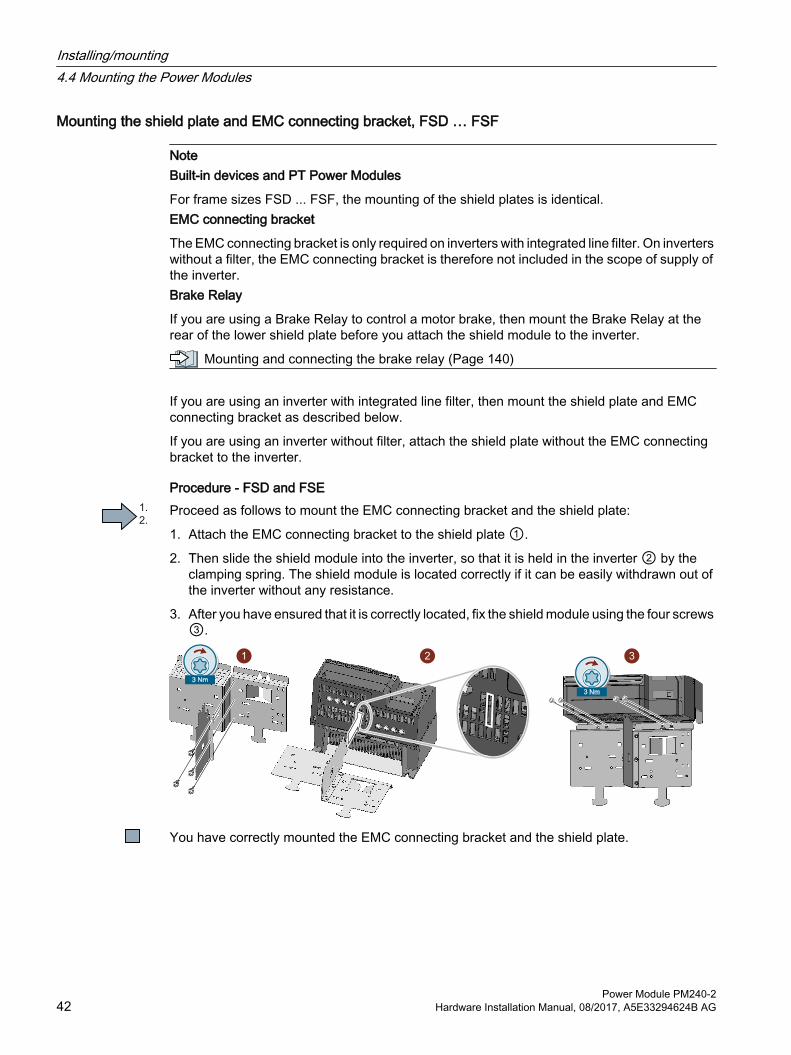
Procedure - FSD and FSEProceed as follows to mount the EMC connecting bracket and the shield plate:
1. Attach the EMC connecting bracket to the shield plate ①.
2. Then slide the shield module into the inverter, so that it is held in the inverter ② by the clamping spring. The shield module is located correctly if it can be easily withdrawn out of the inverter without any resistance.
3. After you have ensured that it is correctly located, fix the shield module using the four screws ③.
You have correctly mounted the EMC connecting bracket and the shield plate.
Installing/mounting4.4 Mounting the Power Modules
Power Module PM240-242 Hardware Installation Manual, 08/2017, A5E33294624B AG
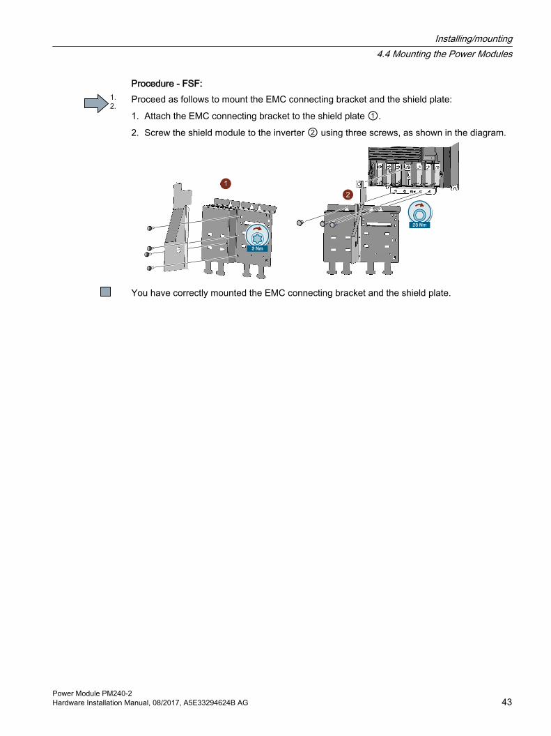
Procedure - FSF:Proceed as follows to mount the EMC connecting bracket and the shield plate:
1. Attach the EMC connecting bracket to the shield plate ①.
2. Screw the shield module to the inverter ② using three screws, as shown in the diagram.
You have correctly mounted the EMC connecting bracket and the shield plate.
Installing/mounting4.4 Mounting the Power Modules
Power Module PM240-2Hardware Installation Manual, 08/2017, A5E33294624B AG 43

4.4.5 Hoisting gear FSD ... PSF
Hoisting gear - Built-in devices
Use crane lifting lugs and the appropriate hoist‐ing gear when mounting built-in devices.Power Module weights:
Technical data (Page 73).
Hoisting gear - PT devicesUse the hoisting gear shown below when mounting the Power Modules
Alternatively, you have the option of attaching mounting grips onto the Power Module. Mounting grips for PT Power Modules (Page 125).
Power Module weights: Technical data (Page 73).
Installing/mounting4.4 Mounting the Power Modules
Power Module PM240-244 Hardware Installation Manual, 08/2017, A5E33294624B AG

4.5 Additional componentsDepending on the particular application, additional components may be required for your system. Information about additional components is provided in the following Sections:
Connection overview (Page 55)
Accessories (Page 119).
Installing/mounting4.5 Additional components
Power Module PM240-2Hardware Installation Manual, 08/2017, A5E33294624B AG 45

Installing/mounting4.5 Additional components
Power Module PM240-246 Hardware Installation Manual, 08/2017, A5E33294624B AG
Connecting-up 5Install the converter so that you are compliant with local regulations for erecting and installing low-voltage systems.
NoteSafety devices
Install suitable protective equipment between the line supply and converter.
Technical data (Page 73)
NoteOperating displays for converter operation
If, when switching over a function from ON to OFF, an LED or other similar display is not lit or not active; this does not indicate that the device is switched-off or in a no-current condition.
To protect against indirectly touching part of the motor circuit of an inverter and to automatically shut down in the case of a fault according to DIN EN 60364-4-41 (VDE 0100-410). (http://support.automation.siemens.com/WW/view/en/103474630)
WARNING
Electric shock due to faulty contact protection
Due to faulty contact protection, the power connections of the inverter may be openly accessible. Touching live power connections can result in death or severe injury.● Make the openings for the inverter power connections just large enough for the cables to
be routed through.● Cover power connections that are not used so that they cannot be touched. ● Use the dummy plugs provided in the accessory pack for unused terminals.
WARNING
Fire or electric shock due to unsuitable residual-current protective devices
The inverter may create a current through the protective conductor. The current through the protective conductor can cause the residual current device (RCD) or residual current monitor (RCM) to incorrectly trip (nuisance trip). In the case of a ground fault, the fault current can contain a DC component, which prevents the RCD or RCM from tripping, with the risk of subsequent fire or electric shock.● Use the protection and monitoring devices recommended in the documentation.
Power Module PM240-2Hardware Installation Manual, 08/2017, A5E33294624B AG 47
CAUTION
Burns due to touching hot surfaces
Certain components (e.g. the heat sink or line reactor) can become very hot during operation. The components can remain hot for some time after operation. Touching hot surfaces can cause burns to the skin.● Do not touch hot components during operation or immediately following operation.
WARNING
Electric shock and fire hazard caused by unsuitable protective equipment
Overcurrent protective equipment that trips too late or not all can cause electric shock or fire.● In the case of a conductor-conductor or conductor-ground short-circuit, ensure that the
short-circuit current at the point where the converter is connected to the line supply corresponds as a minimum to the requirements of the protective equipment used.
● You must use an additional residual-current protective device (RCD) if the required short-circuit current is not reached for a conductor-ground short circuit. Especially for TT line systems, it is possible that the required short-circuit current is not reached.
● It is not permissible that the short-circuit current exceeds the SCCR or the ICC of the converter and the disconnecting capacity of the protective equipment.
Protection and monitoring equipmentTo provide protection against short-circuit, use the overcurrent devices listed in Technical data (fuses, circuit breakers etc.).
If the apparent impedance of the line supply at the infeed point is not suitable, so that fuses do not rupture in the specified time in the case of insulation failure (ground fault, fault to frame), then you must use additional fault current protective devices RCD (RCCB or MRCD), type B.
In order that an RCD does not unnecessarily trip as a result of operational leakage currents, the following preconditions must be fulfilled:
● The neutral point of the line supply is grounded.
● For inverters with rated input currents ≤ 125 A referred to LO, use an RCCB type B with a response limit current of 300 mA. Connect the RCCB in series with the overcurrent protective devices.
Connecting-up
Power Module PM240-248 Hardware Installation Manual, 08/2017, A5E33294624B AG

● For inverters with rated input currents> 125 A referred to LO, use a type B MRCD (for example, from the Bender company). An MRCD comprises an RCM (differential current monitoring device), a measuring current transducer and a circuit breaker with additional undervoltage release, listed in the Technical data. An example of an MRCD design is provided in the following diagram.
PE
Figure 5-1 MRCD
● A dedicated RCD is used for every inverter.
● The motor cables are shorter than 50 m (164 ft) shielded, or 100 m (328 ft) unshielded. Additional information about motor cables
Length of the motor cable (Page 59)
Further protection and monitoring equipment (https://support.industry.siemens.com/cs/ww/en/view/109486009)
Connecting-up
Power Module PM240-2Hardware Installation Manual, 08/2017, A5E33294624B AG 49

5.1 Permissible line suppliesThe converter is designed for the following line supplies according to IEC 60364-1 (2005).
● TN system
● TT system
● IT system
General requirements on line supplyThe plant builder or machine manufacturer must ensure for operation with rated current Irated that the voltage drop between the transformer input terminals and the inverter when operated with its rated values is less than 4% of the transformer rated current
Restrictions for installation altitudes above 2000 mAbove an installation altitude of 2000 m, the permissible line supplies are restricted.
Restrictions for special ambient conditions (Page 108)
5.1.1 TN line system
A TN line system transfers the PE protective conductor to the installed plant or system us‐ing a cable.Generally, in a TN line system the neutral point is grounded. There are versions of a TN system with a grounded line conductor, e.g. with grounded L1.A TN line system can transfer the neutral con‐ductor N and the PE protective conductor ei‐ther separately or combined.
Inverter operated on a TN line system● Inverter with integrated or external line filter:
– Operation on TN line systems with grounded neutral point permissible.
– Operation on TN line systems with grounded line conductor not permissible.
● Inverter without line filter:
– Operation on all TN line systems ≤ 600 V permissible
– Operation on TN line systems > 600 V and grounded neutral point permissible.
– Operation on TN line systems > 600 V and grounded line conductor not permissible.
Connecting-up5.1 Permissible line supplies
Power Module PM240-250 Hardware Installation Manual, 08/2017, A5E33294624B AG
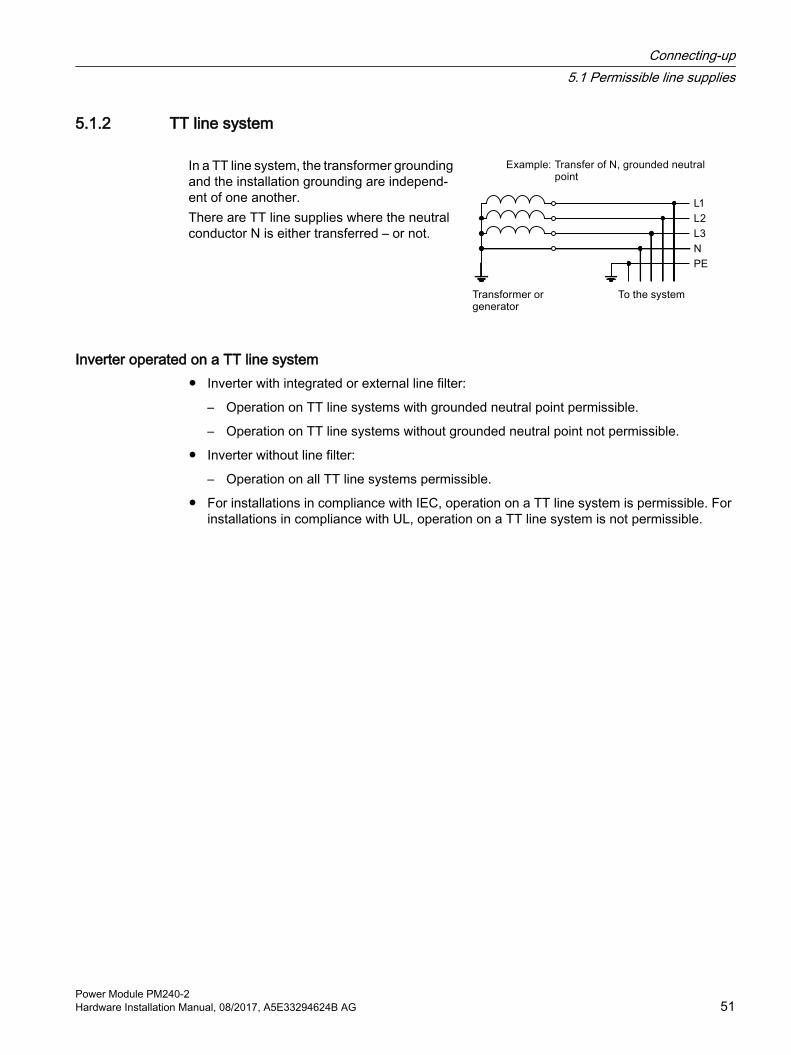
5.1.2 TT line system
In a TT line system, the transformer grounding and the installation grounding are independ‐ent of one another.There are TT line supplies where the neutral conductor N is either transferred – or not.
Inverter operated on a TT line system● Inverter with integrated or external line filter:
– Operation on TT line systems with grounded neutral point permissible.
– Operation on TT line systems without grounded neutral point not permissible.
● Inverter without line filter:
– Operation on all TT line systems permissible.
● For installations in compliance with IEC, operation on a TT line system is permissible. For installations in compliance with UL, operation on a TT line system is not permissible.
Connecting-up5.1 Permissible line supplies
Power Module PM240-2Hardware Installation Manual, 08/2017, A5E33294624B AG 51

5.1.3 IT system
In an IT line system, all of the conductors are insulated with respect to the PE protective conductor – or connected to the PE protective conductor through an impedance.There are IT systems with and without transfer of the neutral conductor N.
Inverter operated on an IT line system● Inverters with integrated line filter:
– Operation on IT line systems not permissible.
● Inverter without line filter:
– Operation on all IT line systems permissible.
Behavior of the inverter when a ground fault occursIn some instances, even for a ground fault, the inverter should still remain functional. In cases such as these, you must install an output reactor. This prevents an overcurrent trip or damage to the drive.
Connecting-up5.1 Permissible line supplies
Power Module PM240-252 Hardware Installation Manual, 08/2017, A5E33294624B AG

5.1.4 Protective conductor
WARNING
Electric shock due to interrupted protective conductor
The drive components conduct a high leakage current via the protective conductor. Touching conductive parts when the protective conductor is interrupted can result in death or serious injury.● Dimension the protective conductor as stipulated in the appropriate regulations.
Dimensioning the protective conductorObserve the local regulations for protective conductors subject to an increased leakage current at the site of operation.
① Protective conductor for line feeder cables② Protective conductor for inverter line feeder cables ③ Protective conductor between PE and the control cabinet④ Protective conductor for motor feeder cables
The minimum cross-section of the protective conductor ① … ④ depends on the cross-section of the line or motor feeder cable:
● Line or motor feeder cable ≤ 16 mm2
⇒ Minimum cross-section of the protective conductor = cross-section of the line or motor feeder cable
● 16 mm² < line or motor feeder cable ≤ 35 mm2
⇒ Minimum cross-section of the protective conductor = 16 mm2
● Line or motor feeder cable > 35 mm2 ⇒ Minimum cross-section of the protective conductor = ½ cross-section of the line or motor feeder cable
Connecting-up5.1 Permissible line supplies
Power Module PM240-2Hardware Installation Manual, 08/2017, A5E33294624B AG 53

Additional requirements placed on the protective conductor ①:
● For permanent connection, the protective conductor must fulfill at least one of the following conditions:
– The protective conductor is routed so that it is protected against damage along its complete length.Cables routed inside switch cabinets or enclosed machine housings are considered to be adequately protected against mechanical damage.
– As a conductor of a multi-conductor cable, the protective conductor has a cross-section ≥ 2.5 mm² Cu.
– For an individual conductor, the protective conductor has a cross-section ≥ 10 mm² Cu.
– The protective conductor consists of two individual conductors with the same cross-section.
● When connecting a multi-core cable using an industrial plug connector according to EN 60309, the protective conductor must have a cross-section of ≥ 2.5 mm² Cu.
Connecting-up5.1 Permissible line supplies
Power Module PM240-254 Hardware Installation Manual, 08/2017, A5E33294624B AG

5.2 Connecting the line and motor cable at the inverter
5.2.1 Connection overview
NoteLine reactor
A line reactor is not required for the Power Modules FSD … FSF.Line filter
The inverters are available with or without integrated line filter (Class A). For frame sizes FSA … FSC, 3 AC 400 V, there are external filters (Class B) for increased EMC requirements.
Line filter (Page 129)Output reactor
For frame sizes FSD … FSF no output reactor is required in many cases on account of the long cable lengths between the inverter and the motor.
Available output reactors: Output reactor (Page 141)
Braking resistor
Connect the braking resistor to the inverter via the R1 and R2 terminals.
Figure 5-2 Block diagram of the inverter, FSA ... FSC
Connecting-up5.2 Connecting the line and motor cable at the inverter
Power Module PM240-2Hardware Installation Manual, 08/2017, A5E33294624B AG 55
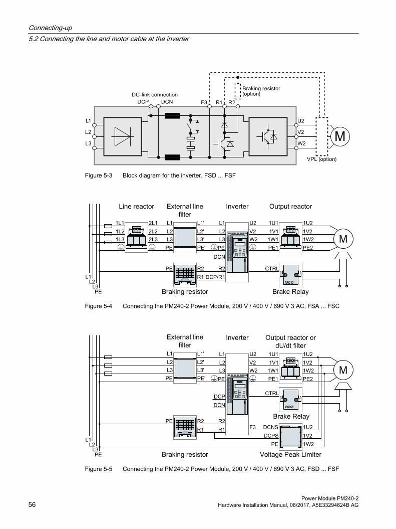
Figure 5-3 Block diagram for the inverter, FSD ... FSF
Figure 5-4 Connecting the PM240-2 Power Module, 200 V / 400 V / 690 V 3 AC, FSA ... FSC
Figure 5-5 Connecting the PM240-2 Power Module, 200 V / 400 V / 690 V 3 AC, FSD ... FSF
Connecting-up5.2 Connecting the line and motor cable at the inverter
Power Module PM240-256 Hardware Installation Manual, 08/2017, A5E33294624B AG

Figure 5-6 Connecting the PM240-2 Power Module, 200 V 1 AC, FSA ... FSC
Figure 5-7 Connecting the PM240-2 Power Module, 200 V 1 AC, FSD ... FSF
NoteConnecting PM240-2 Power Modules, 200 V to 1 AC - only FSA ... FSC
For the 200 V versions and single-phase line systems, connect the phase conductor and neutral conductor to any two of the terminals L1, L2, L3.
Connecting-up5.2 Connecting the line and motor cable at the inverter
Power Module PM240-2Hardware Installation Manual, 08/2017, A5E33294624B AG 57
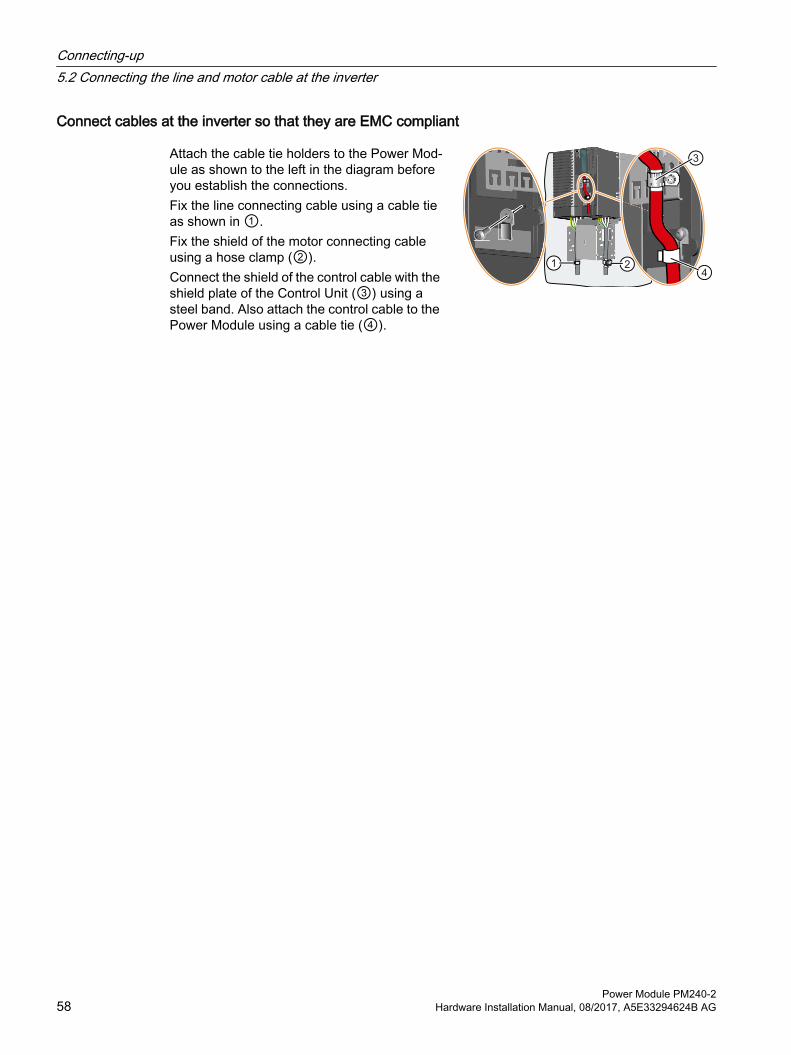
Connect cables at the inverter so that they are EMC compliant
Attach the cable tie holders to the Power Mod‐ule as shown to the left in the diagram before you establish the connections.Fix the line connecting cable using a cable tie as shown in ①.Fix the shield of the motor connecting cable using a hose clamp (②).Connect the shield of the control cable with the shield plate of the Control Unit (③) using a steel band. Also attach the control cable to the Power Module using a cable tie (④).
Connecting-up5.2 Connecting the line and motor cable at the inverter
Power Module PM240-258 Hardware Installation Manual, 08/2017, A5E33294624B AG

5.2.2 Length of the motor cableAlways dimension the motor cable so that the ohmic losses are less than 5 % of the inverter power rating.
The permissible length of the motor cable also depends on the quality of the motor cable and the inverter pulse frequency. The values specified below are applicable for high quality cables, such as CY100 or similar, and for the pulse frequencies set in the factory.
Pulse frequencies (Page 73).
If you set other pulse frequencies, then you must ensure that the EMC category is complied with on the plant or system side.
EMC-compliant wiring is required in order that the inverter complies with the EMC category listed in the following table. EMC-compliant installation of a machine or system (Page 26)
Carefully observe the following section for operation in the first environment: Electromagnetic compatibility of variable-speed drives (Page 111)
Table 5-1 Permissible lengths of motor connecting cables, inverter FSA … FSC
EMC category Second Environment, C2 No EMC categoryInverter with internal
C2 filter with exter‐nal C2 filter
with exter‐nal C1 filter, with output
reactor
without fil‐ter, without output reac‐
tor
without filter, with output reactor
Cable Shielded Shielded Shielded Shielded/unshielded
Shielded Unshielded
200 V 50 m 50 m --- 150 m 150 m 225 m400 V 50 m 1) 50 m 2) 150 m 3) 150 m 150 m 225 m
1) For a low-capacitance motor cable: FSB 100 m, FSC 150 m 2) For a low-capacitance motor cable: FSA 150 m, FSB 100 m, FSC 100 m3) 150 m for voltages in the range 380 V … 415 V,
100 m for voltages in the range 440 V … 480 V
Table 5-2 Permissible cable lengths for the motor connection, FSD … FSE
EMC category Second Envi‐ronment, C2
No EMC category
Inverter with internal C2 filter
with or without filter, with or with‐out output reactor
without filter, with two output re‐actors in series
Cable Shielded Shielded Unshielded Shielded Unshielded200 V --- 200 m 300 m 350 m 525 m400 V 150 m 200 m 300 m 350 m 525 m690 V 100 m 200 m 300 m --- ---
Connecting-up5.2 Connecting the line and motor cable at the inverter
Power Module PM240-2Hardware Installation Manual, 08/2017, A5E33294624B AG 59
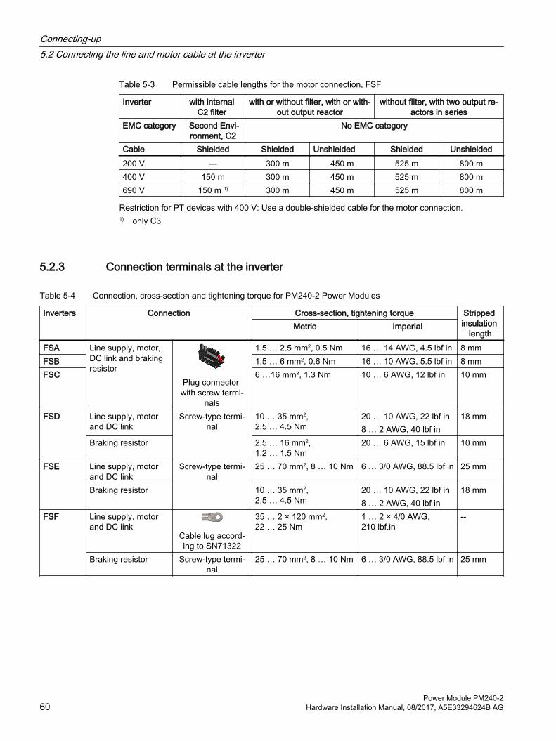
Table 5-3 Permissible cable lengths for the motor connection, FSF
Inverter with internal C2 filter
with or without filter, with or with‐out output reactor
without filter, with two output re‐actors in series
EMC category Second Envi‐ronment, C2
No EMC category
Cable Shielded Shielded Unshielded Shielded Unshielded200 V --- 300 m 450 m 525 m 800 m400 V 150 m 300 m 450 m 525 m 800 m690 V 150 m 1) 300 m 450 m 525 m 800 m
Restriction for PT devices with 400 V: Use a double-shielded cable for the motor connection.1) only C3
5.2.3 Connection terminals at the inverter
Table 5-4 Connection, cross-section and tightening torque for PM240-2 Power Modules
Inverters Connection Cross-section, tightening torque Stripped insulation
lengthMetric Imperial
FSA Line supply, motor, DC link and braking resistor
Plug connector with screw termi‐
nals
1.5 … 2.5 mm2, 0.5 Nm 16 … 14 AWG, 4.5 lbf in 8 mmFSB 1.5 … 6 mm2, 0.6 Nm 16 … 10 AWG, 5.5 lbf in 8 mmFSC 6 …16 mm², 1.3 Nm 10 … 6 AWG, 12 lbf in 10 mm
FSD Line supply, motor and DC link
Screw-type termi‐nal
10 … 35 mm2, 2.5 … 4.5 Nm
20 … 10 AWG, 22 lbf in8 … 2 AWG, 40 lbf in
18 mm
Braking resistor 2.5 … 16 mm2, 1.2 … 1.5 Nm
20 … 6 AWG, 15 lbf in 10 mm
FSE Line supply, motor and DC link
Screw-type termi‐nal
25 … 70 mm2, 8 … 10 Nm 6 … 3/0 AWG, 88.5 lbf in 25 mm
Braking resistor 10 … 35 mm2, 2.5 … 4.5 Nm
20 … 10 AWG, 22 lbf in8 … 2 AWG, 40 lbf in
18 mm
FSF Line supply, motor and DC link
Cable lug accord‐ing to SN71322
35 … 2 × 120 mm2, 22 … 25 Nm
1 … 2 × 4/0 AWG, 210 lbf.in
--
Braking resistor Screw-type termi‐nal
25 … 70 mm2, 8 … 10 Nm 6 … 3/0 AWG, 88.5 lbf in 25 mm
Connecting-up5.2 Connecting the line and motor cable at the inverter
Power Module PM240-260 Hardware Installation Manual, 08/2017, A5E33294624B AG

5.2.4 Establishing connections
ProcedureProceed as follows to establish the connections:
1. Ensure that the device is in a no-voltage condition and the DC link is discharged.
2. Establish the connections as described in the following sections.
This means that you have established the connections.
Connections for frame sizes FSA … FSC
The Power Modules are equipped with withdraw‐able plug connectors that cannot be inadvertently interchanged.To remove a plug connector, you must release it by pressing on the red lever.① Release lever
Connections for frame sizes FSD … FSF
You must remove the covers from the con‐nections in order to connect the line supply, braking resistor and motor to the inverter.In addition, for frame sizes FSD and FSE, release the two terminal screws on the con‐nections for the motor and braking resistor, and remove the dummy plug.For frame size FSF you must breakout the openings from the connection cover for the power connections. Use side cutters or a fine saw blade.
1
2
FSD … FSF: remove the top covers
Connecting-up5.2 Connecting the line and motor cable at the inverter
Power Module PM240-2Hardware Installation Manual, 08/2017, A5E33294624B AG 61

FSD, FSE: remove the lower covers
3
FSF: remove the lower covers
Figure 5-8 Connections for the line supply, motor and braking resistor
Connecting-up5.2 Connecting the line and motor cable at the inverter
Power Module PM240-262 Hardware Installation Manual, 08/2017, A5E33294624B AG

You must re-attach the connection covers in order to re-establish the touch protection of the inverter after it has been connected up.
Connecting DC link or braking resistor
Use the rubber cable gland as shown in the right-hand figure for connecting the braking resistor.Using a sharp knife, cut the cap of the cable gland corresponding to the diameter of the connection ca‐ble of the braking resistor and establish the connec‐tions.Connect the braking resistor at the R1 and R2 ter‐minals.An optional shield plate is available as strain relief for the connection cable of the braking resistor.
Top shield plate - FSD … FSF (Page 120)The connections for the DC link have not been re‐leased in the current version.
Connecting-up5.2 Connecting the line and motor cable at the inverter
Power Module PM240-2Hardware Installation Manual, 08/2017, A5E33294624B AG 63
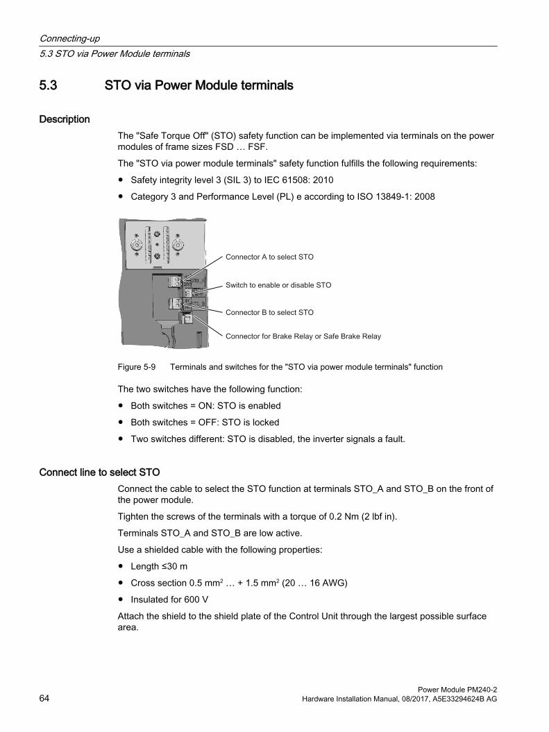
5.3 STO via Power Module terminals
DescriptionThe "Safe Torque Off" (STO) safety function can be implemented via terminals on the power modules of frame sizes FSD … FSF.
The "STO via power module terminals" safety function fulfills the following requirements:
● Safety integrity level 3 (SIL 3) to IEC 61508: 2010
● Category 3 and Performance Level (PL) e according to ISO 13849‑1: 2008
Figure 5-9 Terminals and switches for the "STO via power module terminals" function
The two switches have the following function:
● Both switches = ON: STO is enabled
● Both switches = OFF: STO is locked
● Two switches different: STO is disabled, the inverter signals a fault.
Connect line to select STOConnect the cable to select the STO function at terminals STO_A and STO_B on the front of the power module.
Tighten the screws of the terminals with a torque of 0.2 Nm (2 lbf in).
Terminals STO_A and STO_B are low active.
Use a shielded cable with the following properties:
● Length ≤30 m
● Cross section 0.5 mm2 … + 1.5 mm2 (20 … 16 AWG)
● Insulated for 600 V
Attach the shield to the shield plate of the Control Unit through the largest possible surface area.
Connecting-up5.3 STO via Power Module terminals
Power Module PM240-264 Hardware Installation Manual, 08/2017, A5E33294624B AG

Use conductor end sleeves, stripped length 7 mm.
NoteConfiguring a safety function
In order to use the "STO via power module terminals" safety function, the function has to be configured with a commissioning tool.
Further information and wiring examples are to be found in the "Safety Integrated" Function Manual.
Manuals for your inverter (Page 149)
Connecting-up5.3 STO via Power Module terminals
Power Module PM240-2Hardware Installation Manual, 08/2017, A5E33294624B AG 65

5.4 Connecting the motor to the inverter in a star or delta connectionStandard induction motors with a rated power of approximately ≤ 3 kW are normally connected in a star/delta connection (Y/Δ) at 400 V/230 V. For a 400‑V line supply, you can connect the motor to the inverter either in a star or in a delta connection.
Operating the motor in a star connection
In a star connection, the motor can provide its rated torque MN in the range 0 … rated frequen‐cy fN.Rated voltage UN = 400 V is available at a rated frequency fN = 50 Hz.The motor goes into field weakening above the rated frequency. In field weakening, the availa‐ble motor torque decreases linearly with 1/f. In field weakening, the available power remains constant.
Operating the motor in a delta connection with 87 Hz characteristic
In a delta connection, the motor is oper‐ated with a voltage and frequency above its rated values. As a consequence, the motor power is increased by a factor √3 ≈ 1.73.In the range f = 0 … 87 Hz, the motor can output its rated torque MN.The maximum voltage U = 400 V is avail‐able at a frequency of f = √3 × 50 Hz ≈ 87 Hz.
The motor only goes into field weakening above 87 Hz.
The higher motor power when operated with an 87 Hz characteristic has the following disadvantages:
● The inverter must supply approximately 1.73x current. Select an inverter based on its rated current - and not its rated power.
● The motor temperature increases more significantly than when operated with f ≤ 50 Hz.
● The motor must have windings that are approved for a voltage > rated voltage UN.
● As the fan impeller rotates faster, the motor has a higher noise level than operation with f ≤ 50 Hz.
Connecting-up5.4 Connecting the motor to the inverter in a star or delta connection
Power Module PM240-266 Hardware Installation Manual, 08/2017, A5E33294624B AG

Service and maintenance 6WARNING
Fire or electric shock due to defective components
If an overcurrent protection device is triggered, the inverter may be defective. A defective inverter may cause a fire or electric shock.● Have the inverter and the overcurrent protection device checked by a specialist.
Repair
WARNING
Fire or electric shock due to improper repair
Improper repair of the inverter may cause malfunctions or result in consequential damage such as fire or electric shock.● Only commission the following persons to repair the inverter:
– Siemens customer service– A repair center that has been authorized by Siemens– Specialist personnel who are thoroughly acquainted with all the warnings and operating
procedures contained in this manual.● Only use original spare parts when carrying out repairs.
Power Module PM240-2Hardware Installation Manual, 08/2017, A5E33294624B AG 67
6.1 MaintenanceThe purpose of maintenance is to maintain the specified condition of the Power Module. Regularly remove dirt and pollution, and replace the fan in plenty of time. Replacing a fan (Page 70)
Cleaning
Inverters with IP20 degree of protection - built-in unitsClean the inverter with an anti-static brush, a vacuum cleaner and areas that are difficult to access, using dry compressed air (max. 1 bar).
Inverters with push-through technology – PT devicesClean the heatsink at regular intervals. If necessary, remove the air deflection plate at the rear. Use a torque of 2 Nm when reconnecting. The fans must be installed if you clean the heatsink using water.
Ventilation The devices must be installed in a cabinet. Ensure that the cabinet's ventilation slots are not blocked. Check that the fan is functioning correctly.
Cables and screw terminals Regularly check the cables for damage, and immediately replace any defective parts.
Regularly check that the screw terminals have been correctly tightened. Retighten the screws if necessary.
Note
The actual maintenance intervals depend on the installation and operating conditions.
Siemens offers its customers support in the form of service contracts. For further information, contact your Siemens regional office or sales office.
Service and maintenance6.1 Maintenance
Power Module PM240-268 Hardware Installation Manual, 08/2017, A5E33294624B AG
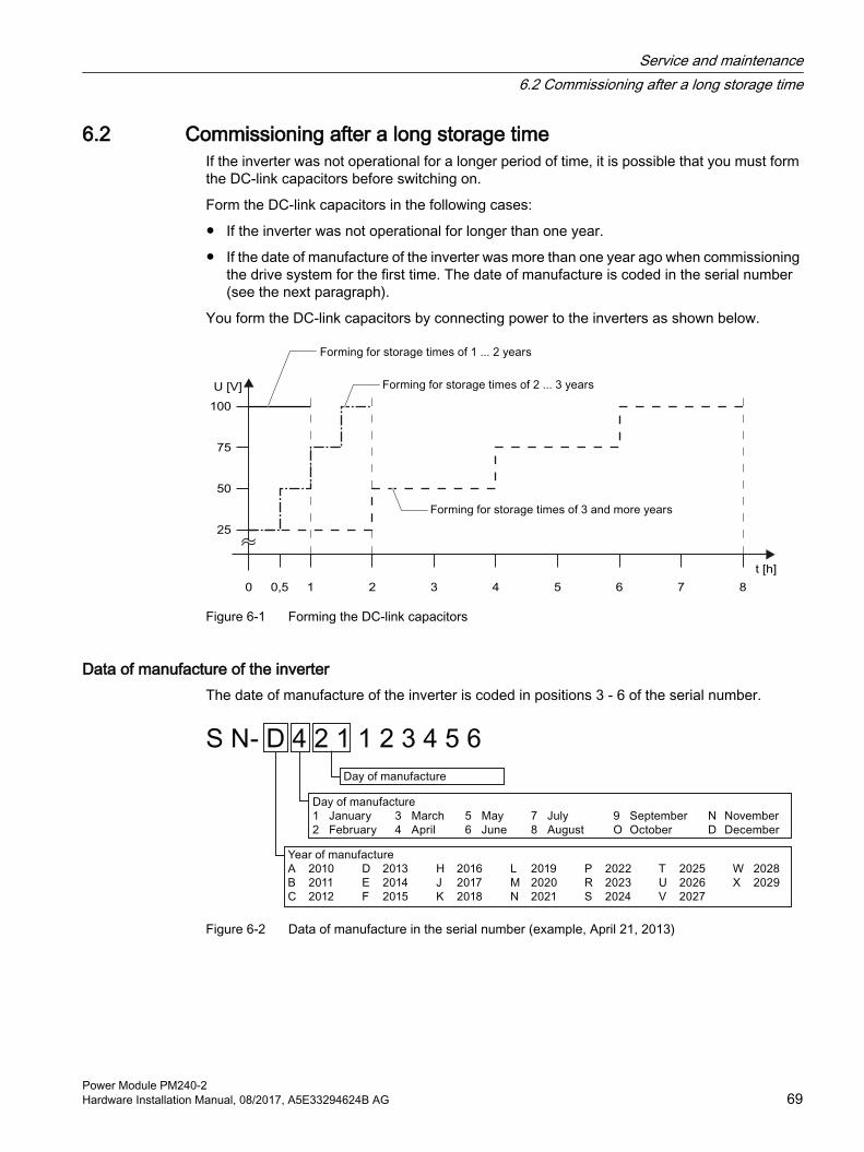
6.2 Commissioning after a long storage timeIf the inverter was not operational for a longer period of time, it is possible that you must form the DC-link capacitors before switching on.
Form the DC-link capacitors in the following cases:
● If the inverter was not operational for longer than one year.
● If the date of manufacture of the inverter was more than one year ago when commissioning the drive system for the first time. The date of manufacture is coded in the serial number (see the next paragraph).
You form the DC-link capacitors by connecting power to the inverters as shown below.
50
25
0 10,5 2 3 4 5 6 7 8
75
100
U [V]
t [h]
Figure 6-1 Forming the DC-link capacitors
Data of manufacture of the inverterThe date of manufacture of the inverter is coded in positions 3 - 6 of the serial number.
Figure 6-2 Data of manufacture in the serial number (example, April 21, 2013)
Service and maintenance6.2 Commissioning after a long storage time
Power Module PM240-2Hardware Installation Manual, 08/2017, A5E33294624B AG 69

6.3 Replacing a fanFor frame sizes FSA … FSC the fan module is installed at the bottom. For frame sizes FSD … FSF it is located at the top.
For frame sizes FSA and FSB the fan module has one fan, for frame sizes FSC ... FSF, two fans.
Service life of the fanThe average service life of the fan is 40,000 hours. In practice, however, the service life may deviate from this value. Especially a dusty environment can block up the fan.
The fan must be replaced in good time to ensure that the inverter is ready for operation.
6.3.1 Fan replacement FSA … FSC
Replacing the fan modules for inverters, frame sizes FSA … FSCProceed as follows to replace a fan module:
1. Switch-off the inverter, and wait 5 minutes until the DC link capacitors have been discharged.
2. Withdraw the line and motor cable plug connectors and, if available, remove the braking resistor from the Power Module.
3. Remove the shield plate from the Power Module.
4. Remove the fan module from the Power Module in steps ① and ② as shown in the diagram. Use a screwdriver if necessary.
5. Install the new fan module in the inverse sequence.
You have replaced the fan module.
Service and maintenance6.3 Replacing a fan
Power Module PM240-270 Hardware Installation Manual, 08/2017, A5E33294624B AG

6.3.2 Fan replacement FSD … FSF
Removing the fan unit, FSD … FSF
ProcedureProceed as follows to remove the fan unit:
1. Switch off the inverter power supply.
WARNING
Electric shock due to residual charge in power components
After the power supply has been switched off, it takes up to 5 min. until the capacitors in the inverter have discharged so that the remaining charge is at a non-hazardous level.● Check the voltage at the inverter connections before you carry out any installation work.
2. Remove the fan unit from the Power Module in steps ① and ② as shown in the diagram. Use a screwdriver if necessary.
3. Additionally for PT devices:Remove the interior fan as shown below.
Service and maintenance6.3 Replacing a fan
Power Module PM240-2Hardware Installation Manual, 08/2017, A5E33294624B AG 71

You have withdrawn the fan unit.
Installing the fan unit, FSD … FSFInstall the fan unit in the reverse order to what is described above.
When inserting the fan unit, you establish the electrical connection between the inverter and fan unit.
Service and maintenance6.3 Replacing a fan
Power Module PM240-272 Hardware Installation Manual, 08/2017, A5E33294624B AG

Technical data 7Power loss of the Power Modules
NotePower loss for the FSA … FSC Power Modules
The values specified for the power loss are typical values at 100% of the rated speed and 100% of the load corresponding to Low Overload.Power loss for the FSD … FSF Power Modules
The values specified for the power loss are typical values at 90% of the rated speed and 100% of the load corresponding to Low Overload.
Protective organs for the Power ModuleThe fuses listed in the following tables are examples of suitable fuses.
Additional components for branch protection are available in the Internet:
Branch protection and short-circuit strength according to UL and IEC (https://support.industry.siemens.com/cs/ww/en/view/109486009)
Frequency with which the DC link is prechargedThe minimum pre-charging cycle is 120 s. Shorter pre-charging cycles can shorten the service life of the Power Module.
Power Module PM240-2Hardware Installation Manual, 08/2017, A5E33294624B AG 73

7.1 Electromagnetic compatibility - Overview
Electromagnetic compatibility according to EN61800-3
Property VersionInterference immunity The inverters are suitable for use in the first and second industrial environmentsInterference emission - second environment
Category C2 for inverters with integrated radio interference suppression filterCategory C2 for inverters without filter with optional external radio interference suppression
filter for grounded line supplies (recommended for operation in conjunction with a residual current protective device RCD)
Category C3 for 690V inverters with integrated radio interference suppression filter, frame size FSF
Category C4 for inverters without integrated radio interference suppression filter for opera‐tion on IT line supplies
Additional information as well as conditions for using the inverter in the first environment are provided in the following Section:
Electromagnetic compatibility of variable-speed drives (Page 111).
Technical data7.1 Electromagnetic compatibility - Overview
Power Module PM240-274 Hardware Installation Manual, 08/2017, A5E33294624B AG

7.2 Ambient conditions
Property VersionAmbient conditions for transport in the transport packagingClimatic ambient conditions ‑ 40° C … + 70° C, according to Class 2K4 to EN 60721‑3‑2
maximum humidity 95% at 40° CMechanical ambient condi‐tions
● FSA … FSC: Shock and vibration permissible according to 1M2 to EN 60721‑3‑2● FSD … FSF: Shock and vibration permissible according to 2M3 to EN 60721‑3‑2
Protection against chemical substances
Protected according to Class 2C2 to EN 60721‑3‑2
Biological ambient condi‐tions
Suitable according to Class 2B1 to EN 60721‑3‑2
Ambient conditions for long-term storage in the product packagingClimatic ambient conditions ‑ 25° C … + 55° C, according to Class 1K3 to EN 60721‑3‑1Protection against chemical substances
Protected according to Class 1C2 to EN 60721‑3‑1
Biological ambient condi‐tions
Suitable according to class 1B1 to EN 60721‑3‑1
Ambient conditions in operationInstallation altitude Up to 1000 m above sea level without limitations
Restrictions for special ambient conditions (Page 108)Climatic ambient conditions 1)
● FSA ... FSC ambient operating temperature 2)
– For operation according to Low Overload: -10° C … +40° C – For operation according to High Overload: -10° C … +50° C – Restrictions for special ambient conditions (Page 108)
● FSD ... FSF ambient operating temperature 2) – For operation according to Low Overload: -20° C … +40° C– For operation according to High Overload: -20° C … +50° C– Restrictions for special ambient conditions (Page 108)
● Relative humidity: 5 … 95%, condensation not permitted● Oil mist, salt mist, ice formation, condensation, dripping water, spraying water, splashing
water and water jets are not permittedMechanical ambient condi‐tions
Shock and vibration permissible, according to Class 3M1 to EN 60721‑3‑3Vibration test during operation according to IEC 60068-2-6 Test Fc (sinusoidal) ● 0 ... 57 Hz: 0.075 mm deflection amplitude● 57 ... 150 Hz: 1 g acceleration amplitude● 10 frequency cycles per axisShock test according to IEC 60068-2-27 Test Ea (half-sine)● 5 g peak acceleration● 30 ms duration● 3 shocks in all three axes in both directions
Protection against chemical substances
● FSA … FSC: Protected according to 3C2 to EN 60721‑3‑3● FSD … FSF: 3C3 protection according to EN 60721‑3‑3
Technical data7.2 Ambient conditions
Power Module PM240-2Hardware Installation Manual, 08/2017, A5E33294624B AG 75

Property VersionBiological ambient condi‐tions
Suitable according to 3B1 to EN 60721‑3‑3
Pollution Suitable for environments with degree of pollution 2 according to EN 61800-5-1Cooling Forced air cooling AF, according to EN 60146Cooling air Clean and dry air
1) Increased ruggedness regarding temperature range and relative humidity; therefore better than 3K3 according to EN 60721-3-3
2) Observe the permissible ambient operating temperatures for the Control Unit and the Operator Panel (IOP-2 or BOP‑2).
Technical data7.2 Ambient conditions
Power Module PM240-276 Hardware Installation Manual, 08/2017, A5E33294624B AG

7.3 Overload capability of the inverterOverload capability is the property of the inverter to temporarily supply a current that is higher than the rated current to accelerate a load. Two typical load cycles are defined to clearly demonstrate the overload capability: "Low Overload" and "High Overload"
Definitions
Base loadConstant load between the accelerating phases of the drive
Low Overload High Overload● LO base load input current
Permissible input current for a "Low Overload" load cycle
● LO base load output currentPermissible output current for a "Low Overload" load cycle
● LO base load powerRated power based on the LO base load output current
● HO base load input currentPermissible input current for a "High Overload" load cycle
● HO base load output currentPermissible output current for a "High Overload" load cycle
● HO base load powerRated power based on the HO base load output current
If not specified otherwise, the power and current data in the technical data always refer to a load cycle according to Low Overload.
We recommend the "SIZER" engineering software to select the inverter.
You will find additional information about SIZER on the Internet: Download SIZER (http://support.automation.siemens.com/WW/view/en/10804987/130000).
Load cycles and typical applications:
"Low Overload" load cycle "High Overload" load cycleThe "Low Overload" load cycle assumes a uniform base load with low requirements placed on brief accelerating p phases. Typi‐cal applications when designing according to "Low Overload" include:● Pumps, fans and compressors● Wet or dry blasting technology● Mills, mixers, kneaders, crushers,
agitators● Basic spindles● Rotary kilns● Extruders
The "High Overload" load cycle permits, for reduced base load, dynamic accelerating phases. Typical applications when designing according to "High Overload" include:● Horizontal and vertical conveyor
technology (conveyor belts, roller conveyors, chain conveyors)
● Centrifuges● Escalators/moving stairways● Lifters/Lowerers● Elevators● Gantry cranes● Cable railways● Storage and retrieval machines
Technical data7.3 Overload capability of the inverter
Power Module PM240-2Hardware Installation Manual, 08/2017, A5E33294624B AG 77

Typical inverter load cycles
Figure 7-1 "Low Overload" and "High Overload" load cycles
Technical data7.3 Overload capability of the inverter
Power Module PM240-278 Hardware Installation Manual, 08/2017, A5E33294624B AG
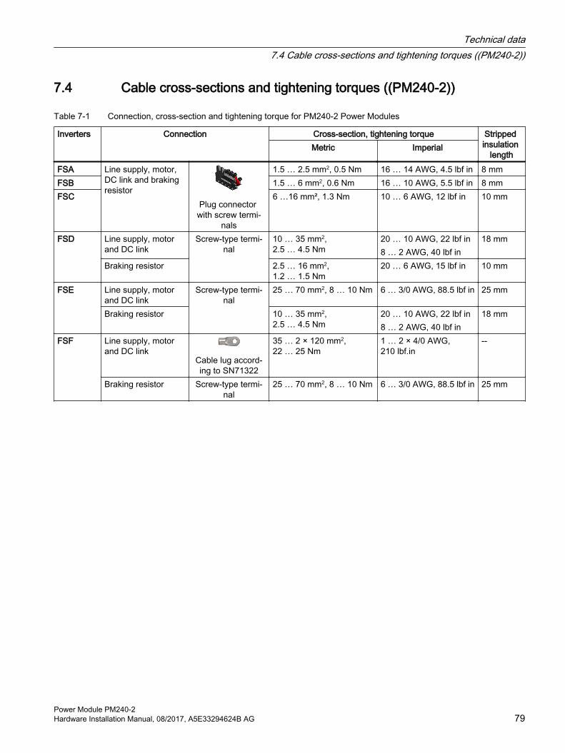
7.4 Cable cross-sections and tightening torques ((PM240-2))
Table 7-1 Connection, cross-section and tightening torque for PM240-2 Power Modules
Inverters Connection Cross-section, tightening torque Stripped insulation
lengthMetric Imperial
FSA Line supply, motor, DC link and braking resistor
Plug connector with screw termi‐
nals
1.5 … 2.5 mm2, 0.5 Nm 16 … 14 AWG, 4.5 lbf in 8 mmFSB 1.5 … 6 mm2, 0.6 Nm 16 … 10 AWG, 5.5 lbf in 8 mmFSC 6 …16 mm², 1.3 Nm 10 … 6 AWG, 12 lbf in 10 mm
FSD Line supply, motor and DC link
Screw-type termi‐nal
10 … 35 mm2, 2.5 … 4.5 Nm
20 … 10 AWG, 22 lbf in8 … 2 AWG, 40 lbf in
18 mm
Braking resistor 2.5 … 16 mm2, 1.2 … 1.5 Nm
20 … 6 AWG, 15 lbf in 10 mm
FSE Line supply, motor and DC link
Screw-type termi‐nal
25 … 70 mm2, 8 … 10 Nm 6 … 3/0 AWG, 88.5 lbf in 25 mm
Braking resistor 10 … 35 mm2, 2.5 … 4.5 Nm
20 … 10 AWG, 22 lbf in8 … 2 AWG, 40 lbf in
18 mm
FSF Line supply, motor and DC link
Cable lug accord‐ing to SN71322
35 … 2 × 120 mm2, 22 … 25 Nm
1 … 2 × 4/0 AWG, 210 lbf.in
--
Braking resistor Screw-type termi‐nal
25 … 70 mm2, 8 … 10 Nm 6 … 3/0 AWG, 88.5 lbf in 25 mm
Technical data7.4 Cable cross-sections and tightening torques ((PM240-2))
Power Module PM240-2Hardware Installation Manual, 08/2017, A5E33294624B AG 79

7.5 Technical data, 200 V inverters
Motors for 200 V Power ModulesFor the 200 V Power Modules, induction motors are permissible in the range from 25% … 150% of the inverter power without any restrictions.
NoteMotors for inverter operation
Only use motors that are suitable for operation with inverters with a DC link.
7.5.1 General data, 200 V inverters
Property VersionLine voltage FSA … FSC 200 V … 240 V 1-ph. AC ± 10% 0.55 kW … 4 kW - LO
0.37 kW … 3 kW - HO200 V … 240 V 3-ph. AC ± 10% 0.55 kW … 7.5 kW - LO
0.37 kW … 5.5 kW - HOFSD … FSF 200 V … 240 V 3-ph. AC ± 10% (in operation -20% < 1 min)
Line supply configurations Grounded TN/TT line supplies or non-grounded IT line supplies Permissible line supplies (Page 50)
Line impedance FSA … FSC
2% ≤ Uk < 4%. For Uk < 2%, we recommend a line reactor, or a Power Module with the next higher power rating.
FSD … FSF No restrictionsPower factor λ FSA … FSC
0.7 without line reactor for Uk ≥ 2%0.85 with line reactor for Uk < 2%
FSD … FSF 0.95Output voltage 0 V … 0.95 3-ph. AC × input voltageInput frequency 50 Hz … 60 Hz, ± 3 Hz Output frequency 0 … 550 Hz, depending on the control modeInrush current < LO base load input currentOvervoltage category ac‐cording to EN 61800-5-1
III for line supplies
Pulse frequency 4 kHz (factory setting), Adjustable as follows in 2 kHz steps: • 2 kHz … 16 kHz for devices with an LO base load output from 0.55 kW … 30 kW. • 2 kHz … 8 kHz for devices with an LO base load output 37 kW and higherIf you increase the pulse frequency, the inverter reduces the maximum output current.
Short-circuit current rating (SCCR) and branch protec‐tion
≤ 100 kA rms Branch protection and short-circuit strength according to UL and IEC (https://
support.industry.siemens.com/cs/ww/en/view/109479152)Braking methods DC braking, compound braking, dynamic braking with integrated braking chopper
Technical data7.5 Technical data, 200 V inverters
Power Module PM240-280 Hardware Installation Manual, 08/2017, A5E33294624B AG

Property VersionDegree of protection ac‐cording to EN 60529
IP20IP55 PT devices outside the control cabinet
Protection class according to EN 61800-5-1
The inverters are devices with protection class I
Touch protection accord‐ing to EN 50274
DGUV regulation 3 when used for the intended purpose
Cooling in compliance with EN 60146
Forced air cooling AF
Dependent on the input voltage and output power
Technical data7.5 Technical data, 200 V inverters
Power Module PM240-2Hardware Installation Manual, 08/2017, A5E33294624B AG 81

7.5.2 Specific technical data, 200 V inverters
Table 7-2 PM240-2, IP20, frame size A, 200 V … 240 V 1 AC / 3 AC
Article No. without filterArticle No. with filter
6SL3210-1PB13-0UL06SL3210-1PB13-0AL0
6SL3210-1PB13-8UL06SL3210-1PB13-8AL0
LO base load power 0.55 kW 0.75 kW 1 AC LO base load input current 7.5 A 9.6 A 3 AC LO base load input current 4.2 A 5.5 A LO base load output current 3.2 A 4.2 A HO base load power 0.37 kW 0.55 kW 1 AC HO base load input current 6.6 A 8.4 A 3 AC HO base load input current 3.0 A 4.2 A HO base load output current 2.3 A 3.2 A Fuse according to IECFuse according to UL, class J
3NA3805 (16 A)15 A
3NA3805 (16 A)15 A
Power loss 0.04 kW 0.04 kW Required cooling air flow 5 l/s 5 l/s Weight without filter 1.4 kg 1.4 kg Weight with filter 1.6 kg 1.6 kg
Table 7-3 PM240-2, PT, frame size A, 200 V … 240 V 1 AC / 3 AC
Article No. without filterArticle No. with filter
6SL3211-1PB13-8UL06SL3211-1PB13-8AL0
LO base load power 0.75 kW 1 AC LO base load input current 9.6 A 3 AC LO base load input current 5.5 A LO base load output current 4.2 A HO base load power 0.55 kW 1 AC HO base load input current 8.4 A 3 AC HO base load input current 4.2 A HO base load output current 3.2 A Fuse according to IECFuse according to UL, class J
3NA3 805 (16 A)15 A
Power loss 0.04 kW Required cooling air flow 5 l/s Weight without filter 1.8 kg Weight with filter 2.0 kg
Technical data7.5 Technical data, 200 V inverters
Power Module PM240-282 Hardware Installation Manual, 08/2017, A5E33294624B AG

Table 7-4 PM240-2, IP20, frame size B, 200 V … 240 V 1 AC / 3 AC
Article No. without filterArticle No. with filter
6SL3210-1PB15-5UL06SL3210-1PB15-5AL0
6SL3210-1PB17-4UL06SL3210-1PB17-4AL0
6SL3210-1PB21-0UL06SL3210-1PB21-0AL0
LO base load power 1.1 kW 1.5 kW 2.2 kW1 AC LO base load input current 13.5 A 18.1 A 24.0 A3 AC LO base load input current 7.8 A 9.7 A 13.6 ALO base load output current 6 A 7.4 A 10.4 AHO base load power 0.75 kW 1.1 kW 1.5 kW1 AC HO base load input current 11.8 A 15.8 A 20.9 A3 AC HO base load input current 5.5 A 7.8 A 9.7 AHO base load output current 4.2 A 6 A 7.4 AFuse according to IECFuse according to UL, class J
3NA3812 (32 A)35 A
3NA3812 (32 A)35 A
3NA3812 (32 A)35 A
Power loss 0.05 kW 0.07 kW 0.12 kWRequired cooling air flow 9.2 l/s 9.2 l/s 9.2 l/sWeight without filter 2.8 kg 2.8 kg 2.8 kg Weight with filter 3.1 kg 3.1 kg 3.1 kg
Table 7-5 PM240-2, PT, frame size B, 200 V … 240 V 1 AC / 3 AC
Article No. without filterArticle No. with filter
6SL3211-1PB21-0UL06SL3211-1PB21-0AL0
LO base load power 2.2 kW 1 AC LO base load input current 24.0 A 3 AC LO base load input current 13.6 A LO base load output current 10.4 A HO base load power 1.5 kW 1 AC HO base load input current 20.9 A 3 AC HO base load input current 9.7 A HO base load output current 7.4 A Fuse according to IECFuse according to UL, class J
3NA3812 (32 A)35 A
Power loss 0.12 kW 1) Required cooling air flow 9.2 l/s Weight without filter 3.4 kg Weight with filter 3.7 kg
1) approx. 0.08 kW through the heat sink
Technical data7.5 Technical data, 200 V inverters
Power Module PM240-2Hardware Installation Manual, 08/2017, A5E33294624B AG 83

Table 7-6 PM240-2, IP 20, frame size C, 200 V … 240 V 1 AC / 3 AC
Article No. without filterArticle No. with filter
6SL3210-1PB21-4UL06SL3210-1PB21-4AL0
6SL3210-1PB21-8UL06SL3210-1PB21-8AL0
LO base load power 3 kW 4 kW 1 AC LO base load input current 35.9 A 43.0 A 3 AC LO base load input current 17.7 A 22.8 A LO base load output current 13.6 A 17.5 A HO base load power 2.2 kW 3 kW 1 AC HO base load input current 31.3 A 37.5 A 3 AC HO base load input current 13.6 A 17.7 A HO base load output current 10.4 A 13.6 A Fuse according to IECFuse according to UL, class J
3NA3820 (50 A)50 A
3NA3820 (50 A)50 A
Power loss 0.14 kW 0.18 kW Required cooling air flow 18.5 l/s 18.5 l/s Weight without filter 5.0 kg 5.0 kg Weight with filter 5.2 kg 5.2 kg
Table 7-7 PM240-2, PT, frame size C, 200 V … 240 V 1 AC / 3 AC
Article No. without filterArticle No. with filter
6SL3211-1PB21-8UL06SL3211-1PB21-8AL0
LO base load power 4 kW 1 AC LO base load input current 43.0 A 3 AC LO base load input current 22.8 A LO base load output current 17.5 A HO base load power 3 kW 1 AC HO base load input current 37.5 A 3 AC HO base load input current 17.7 A HO base load output current 13.6 A Fuse according to IECFuse according to UL, class J
3NA3820 (50 A)50 A
Power loss 0.18 kW 1) Required cooling air flow 18.5 l/s Weight without filter 5.9 kg Weight with filter 6.2 kg
1) approx. 0.09 kW through the heat sink
Technical data7.5 Technical data, 200 V inverters
Power Module PM240-284 Hardware Installation Manual, 08/2017, A5E33294624B AG
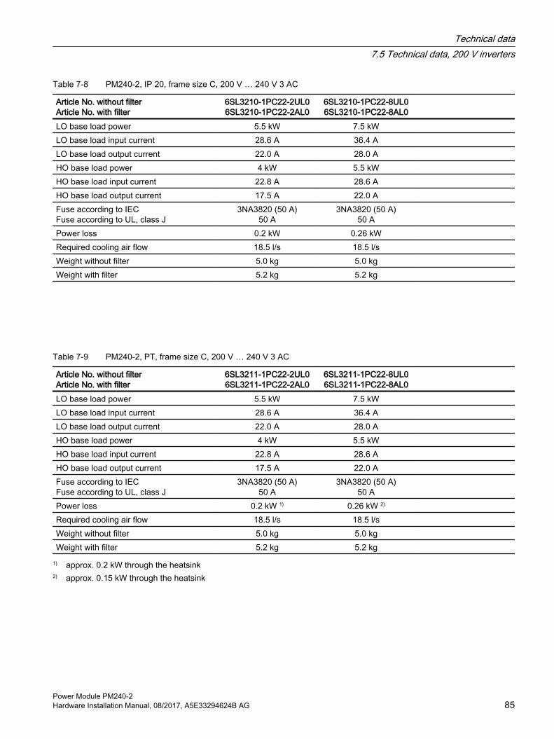
Table 7-8 PM240-2, IP 20, frame size C, 200 V … 240 V 3 AC
Article No. without filterArticle No. with filter
6SL3210-1PC22-2UL06SL3210-1PC22-2AL0
6SL3210-1PC22-8UL06SL3210-1PC22-8AL0
LO base load power 5.5 kW 7.5 kW LO base load input current 28.6 A 36.4 A LO base load output current 22.0 A 28.0 A HO base load power 4 kW 5.5 kW HO base load input current 22.8 A 28.6 A HO base load output current 17.5 A 22.0 A Fuse according to IECFuse according to UL, class J
3NA3820 (50 A)50 A
3NA3820 (50 A)50 A
Power loss 0.2 kW 0.26 kW Required cooling air flow 18.5 l/s 18.5 l/s Weight without filter 5.0 kg 5.0 kg Weight with filter 5.2 kg 5.2 kg
Table 7-9 PM240-2, PT, frame size C, 200 V … 240 V 3 AC
Article No. without filterArticle No. with filter
6SL3211-1PC22-2UL06SL3211-1PC22-2AL0
6SL3211-1PC22-8UL06SL3211-1PC22-8AL0
LO base load power 5.5 kW 7.5 kW LO base load input current 28.6 A 36.4 A LO base load output current 22.0 A 28.0 A HO base load power 4 kW 5.5 kW HO base load input current 22.8 A 28.6 A HO base load output current 17.5 A 22.0 A Fuse according to IECFuse according to UL, class J
3NA3820 (50 A)50 A
3NA3820 (50 A)50 A
Power loss 0.2 kW 1) 0.26 kW 2) Required cooling air flow 18.5 l/s 18.5 l/s Weight without filter 5.0 kg 5.0 kg Weight with filter 5.2 kg 5.2 kg
1) approx. 0.2 kW through the heatsink2) approx. 0.15 kW through the heatsink
Technical data7.5 Technical data, 200 V inverters
Power Module PM240-2Hardware Installation Manual, 08/2017, A5E33294624B AG 85

Table 7-10 PM240-2, IP20, frame size D, 200 V … 240 V 3 AC
Article No. without filter 6SL3210-1PC24-2UL0 6SL3210-1PC25-4UL0 6SL3210-1PC26-8UL0LO base load power 11 kW 15 kW 18.5 kWLO base load input current 40 A 51 A 64 ALO base load output current 42 A 54 A 68 AHO base load power 7.5 kW 11 kW 15 kWHO base load input current 36 A 43 A 56 AHO base load output current 35 A 42 A 54 AFuse according to IEC/ULFuse according to IEC/UL, Class J
3NA3822 (63 A)60 A
3NA3824 (80 A)70 A
3NA3830 (100 A)90 A
Power loss 0.45 kW 0.61 kW 0.82 kWRequired cooling air flow 55 l/s 55 l/s 55 l/sWeight 17 kg 17 kg 17 kg
Table 7-11 PM240-2, PT, Frame Size D, 200 V … 240 V 3 AC
Article No. without filter 6SL3211-1PC26-8UL0 LO base load power 18.5 kW LO base load input current 64 A LO base load output current 68 A HO base load power 15 kW HO base load input current 56 A HO base load output current 54 A Fuse according to IECFuse according to UL, class J
3NA3830 (100 A)90 A
Power loss 0.82 kW 1) Required cooling air flow 55 l/s Weight 19.5 kg
1) approx. 0.72 kW through the heatsink
Technical data7.5 Technical data, 200 V inverters
Power Module PM240-286 Hardware Installation Manual, 08/2017, A5E33294624B AG

Table 7-12 PM240-2, IP20, frame size E, 200 V … 240 V 3 AC
Article No. without filter 6SL3210-1PC28-0UL0 6SL3210-1PC31-1UL0 LO base load power 22 kW 30 kW LO base load input current 76 A 98 A LO base load output current 80 A 104 A HO base load power 18.5 kW 22 kW HO base load input current 71 A 83 A HO base load output current 68 A 80 A Fuse according to IEC/ULFuse according to IEC/UL, Class J
3NA3830 (100 A)100 A
3NA3836 (160 A)150 A
Power loss 0.92 kW 1.28 kW Required cooling air flow 83 l/s 83 l/s Weight 26 kg 26 kg
Table 7-13 PM240-2, PT, frame size E, 200 V to 240 V 3 AC
Article No. without filter 6SL3211-1PC31-1UL0 LO base load power 30 kW LO base load input current 98 A LO base load output current 104 A HO base load power 22 kW HO base load input current 83 A HO base load output current 80 A Fuse according to IECFuse according to UL, class J
3NA3836 (160 A)150 A
Power loss 1.28 kW 1) Required cooling air flow 83 l/s Weight 29 kg
1) approx. 1.1 kW through the heatsink
Technical data7.5 Technical data, 200 V inverters
Power Module PM240-2Hardware Installation Manual, 08/2017, A5E33294624B AG 87

Table 7-14 PM240-2, IP20, frame size F, 200 V … 240 V 3 AC
Article No. without filter 6SL3210-1PC31-3UL0 6SL3210-1PC31-6UL0 6SL3210-1PC31-8UL0LO base load power 37 kW 45 kW 55 kWLO base load input current 126 A 149 A 172 ALO base load output current 130 A 154 A 178 AHO base load power 30 kW 37 kW 45 kWHO base load input current 110 A 138 A 164 AHO base load output current 104 A 130 A 154 AFuse according to IEC/ULFuse according to IEC/UL, Class J
3NA3140 (200 A)175 A
3NA3140 (200 A)200 A
3NA3142 (224 A)250 A
Power loss 1.38 kW 1.72 kW 2.09 kWRequired cooling air flow 153 l/s 153 l/s 153 l/sWeight 57 kg 57 kg 57 kg
Table 7-15 PM240-2, PT, frame size F, 200 V to 240 V 3 AC
Article No. without filter 6SL3211-1PC31-8UL0 LO base load power 55 kW LO base load input current 172 A LO base load output current 178 A HO base load power 45 kW HO base load input current 164 A HO base load output current 154 A Fuse according to IECFuse according to UL, class J
3NA3142 (224 A)250 A
Power loss 2.09 kW 1) Required cooling air flow 153 l/s Weight 60 kg
1) approx. 1.9 kW through the heatsink
Technical data7.5 Technical data, 200 V inverters
Power Module PM240-288 Hardware Installation Manual, 08/2017, A5E33294624B AG
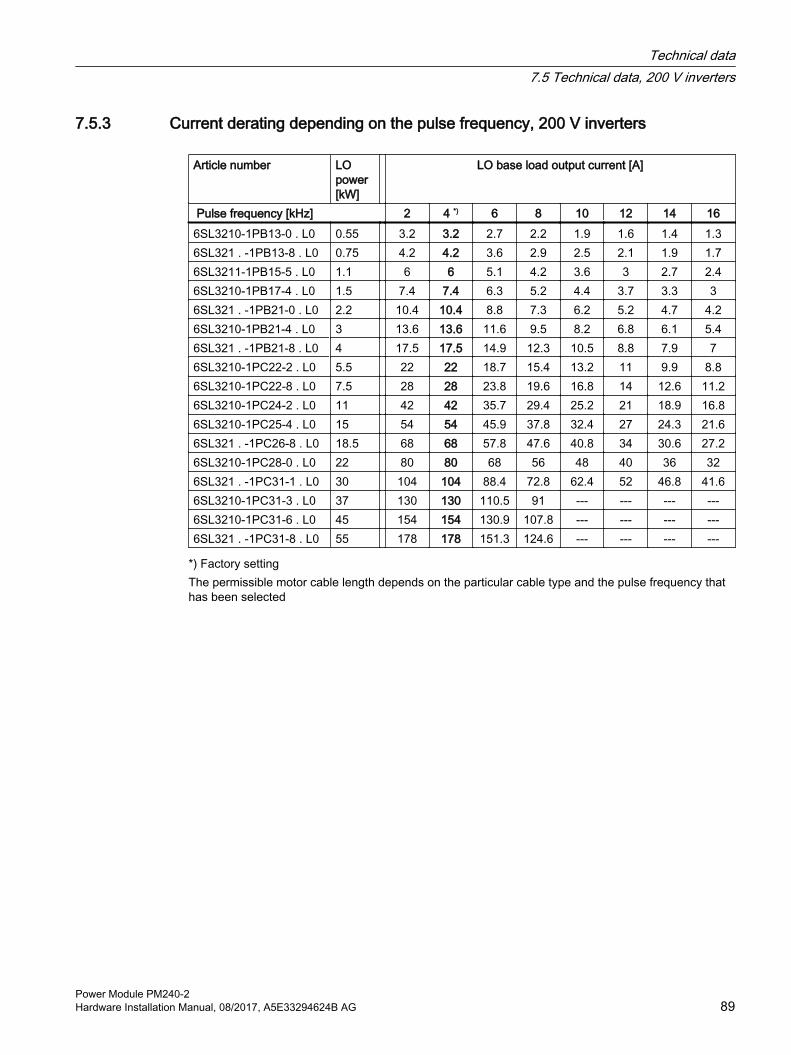
7.5.3 Current derating depending on the pulse frequency, 200 V inverters
Article number LO power [kW]
LO base load output current [A]
Pulse frequency [kHz] 2 4 *) 6 8 10 12 14 166SL3210-1PB13-0 . L0 0.55 3.2 3.2 2.7 2.2 1.9 1.6 1.4 1.36SL321 . -1PB13-8 . L0 0.75 4.2 4.2 3.6 2.9 2.5 2.1 1.9 1.76SL3211-1PB15-5 . L0 1.1 6 6 5.1 4.2 3.6 3 2.7 2.46SL3210-1PB17-4 . L0 1.5 7.4 7.4 6.3 5.2 4.4 3.7 3.3 36SL321 . -1PB21-0 . L0 2.2 10.4 10.4 8.8 7.3 6.2 5.2 4.7 4.26SL3210-1PB21-4 . L0 3 13.6 13.6 11.6 9.5 8.2 6.8 6.1 5.46SL321 . -1PB21-8 . L0 4 17.5 17.5 14.9 12.3 10.5 8.8 7.9 76SL3210-1PC22-2 . L0 5.5 22 22 18.7 15.4 13.2 11 9.9 8.86SL3210-1PC22-8 . L0 7.5 28 28 23.8 19.6 16.8 14 12.6 11.26SL3210-1PC24-2 . L0 11 42 42 35.7 29.4 25.2 21 18.9 16.86SL3210-1PC25-4 . L0 15 54 54 45.9 37.8 32.4 27 24.3 21.66SL321 . -1PC26-8 . L0 18.5 68 68 57.8 47.6 40.8 34 30.6 27.26SL3210-1PC28-0 . L0 22 80 80 68 56 48 40 36 326SL321 . -1PC31-1 . L0 30 104 104 88.4 72.8 62.4 52 46.8 41.66SL3210-1PC31-3 . L0 37 130 130 110.5 91 --- --- --- ---6SL3210-1PC31-6 . L0 45 154 154 130.9 107.8 --- --- --- ---6SL321 . -1PC31-8 . L0 55 178 178 151.3 124.6 --- --- --- ---
*) Factory settingThe permissible motor cable length depends on the particular cable type and the pulse frequency that has been selected
Technical data7.5 Technical data, 200 V inverters
Power Module PM240-2Hardware Installation Manual, 08/2017, A5E33294624B AG 89
7.6 Technical data, 400 V inverters
Motors for 400 V Power ModulesFor the 400 V Power Modules, induction motors are permissible in the range from 25 % … 150 % of the inverter power without any restrictions.
NoteMotors for inverter operation
Only use motors that are suitable for operation with inverters with a DC link.
7.6.1 General data, 400 V inverters
Property VersionLine voltage FSA … FSC 380 V … 480 V 3-ph. AC ± 10%
FSD … FSF 3-ph. AC 380 V … 480 V ± 10% (in operation -20% < 1 min)Line supply configurations Grounded TN/TT line supplies or non-grounded IT line supplies
Permissible line supplies (Page 50)Line impedance FSA … FSC 1% ≤ Uk < 4%, for values smaller than 1%, we recommend a line reactor, or a
Power Module with the next higher power rating. FSD … FSF No restrictions
Power factor λ FSA … FSC FSD … FSF
0.7 without line reactor for Uk ≥ 1%0.85 with line reactor for Uk < 1%> 0.9
Output voltage 3-ph. AC 0 V … 0.95 x input voltage (max.) Input frequency 50 Hz … 60 Hz, ± 3 Hz Output frequency 0 … 550 Hz, depending on the control mode Inrush current < LO base load input current Overvoltage category ac‐cording to EN 61800-5-1
III for line supplies
Pulse frequency Factory setting ● 4 kHz for devices with an LO base load power < 75 kW● 2 kHz for devices with an LO base load power ≥ 75 kWCan be adjusted in 2 kHz steps as follows: ● 2 kHz … 16 kHz for devices with an LO base load power < 55 kW● 2 kHz … 8 kHz for devices with an LO base load output of 55 kW … 90 kW● 2 kHz … 4 kHz for devices with an LO base load output ≥ 110 kWIf you increase the pulse frequency, the inverter reduces the maximum output current.
Short-circuit current rating (SCCR) and branch protec‐tion
≤ 100 kA rms Branch protection and short-circuit strength according to UL and IEC (https://
support.industry.siemens.com/cs/ww/en/view/109479152)Braking methods DC braking, compound braking, dynamic braking with integrated braking chopper
Technical data7.6 Technical data, 400 V inverters
Power Module PM240-290 Hardware Installation Manual, 08/2017, A5E33294624B AG

Property VersionDegree of protection ac‐cording to EN 60529
IP20IP55 PT devices outside the control cabinet
Protection class according to EN 61800-5-1
The inverters are devices with protection class I
Touch protection according to EN 50274
DGUV regulation 3 when used for the intended purpose
Cooling in compliance with EN 60146
Forced air cooling AF
Dependent on the input voltage and output power
Technical data7.6 Technical data, 400 V inverters
Power Module PM240-2Hardware Installation Manual, 08/2017, A5E33294624B AG 91

7.6.2 Specific technical data, 400 V inverters
Table 7-16 PM240-2, IP20, Frame Size A, 3-ph. AC 380 V … 480 V
Article number without filterArticle number with filter
6SL3210-1PE11-8UL16SL3210-1PE11-8AL1
6SL3210-1PE12-3UL16SL3210-1PE12-3AL1
6SL3210-1PE13-2UL16SL3210-1PE13-2AL1
LO base load power 0.55 kW 0.75 kW 1.1 kWLO base load input current 2.3 A 2.9 A 4.1 ALO base load output current 1.7 A 2.2 A 3.1 AHO base load power 0.37 kW 0.55 kW 0.75 kWHO base load input current 2.0 A 2.6 A 3.3 AHO base load output current 1.3 A 1.7 A 2.2 AFuse according to IECFuse according to UL, class J
3NA3805 (16 A)10 A
3NA3805 (16 A)10 A
3NA3805 (16 A)15 A
Power loss 0.04 kW 0.04 kW 0.04 kWRequired cooling air flow 5 l/s 5 l/s 5 l/sWeight without filter 1.3 kg 1.3 kg 1.3 kgWeight with filter 1.5 kg 1.5 kg 1.5 kg
Table 7-17 PM240-2, IP20, Frame Size A, 3-ph. AC 380 V … 480 V
Article number without filterArticle number with filter
6SL3210-1PE14-3UL16SL3210-1PE14-3AL1
6SL3210-1PE16-1UL16SL3210-1PE16-1AL1
6SL3210-1PE18-0UL16SL3210-1PE18-0AL1
LO base load power 1.5 kW 2.2 kW 3.0 kWLO base load input current 5.5 A 7.7 A 10.1 ALO base load output current 4.1 A 5.9 A 7.7 AHO base load power 1.1 kW 1.5 kW 2.2 kWHO base load input current 4.7 A 6.1 A 8.8 AHO base load output current 3.1 A 4.1 A 5.9 AFuse according to IECFuse according to UL, class J
3NA3805 (16 A)20 A
3NA3805 (16 A)30 A
3NA3805 (16 A)30 A
Power loss 0.07 kW 0.1 kW 0.12 kWRequired cooling air flow 5 l/s 5 l/s 5 l/sWeight without filter 1.4 kg 1.4 kg 1.4 kgWeight with filter 1.6 kg 1.6 kg 1.6 kg
Technical data7.6 Technical data, 400 V inverters
Power Module PM240-292 Hardware Installation Manual, 08/2017, A5E33294624B AG

Table 7-18 PM240-2, PT, Frame Size A, 3-ph. AC 380 V … 480 V
Article number without filterArticle number with filter
6SL3211-1PE18-0UL16SL3211-1PE18-0AL1
LO base load power 3.0 kW LO base load input current 10.1 A LO base load output current 7.7 A HO base load power 2.2 kW HO base load input current 8.8 A HO base load output current 5.9 A Fuse according to IECFuse according to UL, class J
3NA3805 (16 A)30 A
Power loss without filter 0.12 kW 1) Required cooling air flow 7 l/s Weight without filter 1.8 kg Weight with filter 2.0 kg
1) approx. 0.1 kW through the heatsink
Table 7-19 PM240-2, IP20, Frame Size B, 3-ph. AC 380 V … 480 V
Article number without filterArticle number with filter
6SL3210-1PE21-1UL06SL3210-1PE21-1AL0
6SL3210-1PE21-4UL06SL3210-1PE21-4AL0
6SL3210-1PE21-8UL06SL3210-1PE21-8AL0
LO base load power 4.0 kW 5.5 kW 7.5 kWLO base load input current 13.3 A 17.2 A 22.2 ALO base load output current 10.2 A 13.2 A 18.0 AHO base load power 3.0 kW 4.0 kW 5.5 kWHO base load input current 11.6 A 15.3 A 19.8 AHO base load output current 7.7 A 10.2 A 13.2 AFuse according to IECFuse according to UL, class J
3NA3812 (32 A)35 A
3NA3812 (32 A)35 A
3NA3812 (32 A)35 A
Power loss 0.11 kW 0.15 kW 0.2 kWRequired cooling air flow 9.2 l/s 9.2 l/s 9.2 l/sWeight without filter 2.9 kg 2.9 kg 3.0 kgWeight with filter 3.1 kg 3.1 kg 3.2 kg
Technical data7.6 Technical data, 400 V inverters
Power Module PM240-2Hardware Installation Manual, 08/2017, A5E33294624B AG 93

Table 7-20 PM240-2, PT, Frame Size B, 3-ph. AC 380 V … 480 V
Article number without filterArticle number with filter
6SL3211-1PE21-8UL06SL3211-1PE21-8AL0
LO base load power 7.5 kW LO base load input current 22.2 A LO base load output current 18.0 A HO base load power 5.5 kW HO base load input current 19.8 A HO base load output current 13.7 A Fuse according to IECFuse according to UL, class J
3NA3812 (32 A)35 A
Power loss 0.2 kW 1) Required cooling air flow 9.2 l/s Weight without filter 3.6 kg Weight with filter 3.9 kg
1) approx. 0.16 kW through the heatsink
Table 7-21 PM240-2, IP20, Frame Size C, 3-ph. AC 380 V … 480 V
Article number without filterArticle number with filter
6SL3210-1PE22-7UL06SL3210-1PE22-7AL0
6SL3210-1PE23-3UL06SL3210-1PE23-3AL0
LO base load power 11.0 kW 15.0 kW LO base load input current 32.6 A 39.9 A LO base load output current 26.0 A 32.0 A HO base load power 7.5 kW 11.0 kW HO base load input current 27.0 A 36.0 A HO base load output current 18.0 A 26.0 A Fuse according to IECFuse according to UL, class J
3NA3820 (50 A)50 A
3NA3820 (50 A)50 A
Power loss 0.3 kW 0.37 kW Required cooling air flow 18.5 l/s 18.5 l/s Weight without filter 4.7 kg 4.8 kg Weight with filter 5.3 kg 5.4 kg
Technical data7.6 Technical data, 400 V inverters
Power Module PM240-294 Hardware Installation Manual, 08/2017, A5E33294624B AG

Table 7-22 PM240-2, PT, Frame Size C, 3-ph. AC 380 V … 480 V
Article number without filterArticle number with filter
6SL3211-1PE23-3UL06SL3211-1PE23-3AL0
LO base load power 15.0 kW LO base load input current 39.9 A LO base load output current 32.0 A HO base load power 11.0 kW HO base load input current 36.0 A HO base load output current 26.0 A Fuse according to IECFuse according to UL, class J
3NA3820 (50 A)50 A
Power loss 0.37 kW 1) Required cooling air flow 18.5 l/s Weight without filter 5.8 kg Weight with filter 6.3 kg
1) approx. 0.3 kW through the heatsink
Table 7-23 PM240-2, IP20, Frame Size D, 3-ph. AC 380 V … 480 V
Article number without filterArticle number with filter
6SL3210-1PE23-8UL06SL3210-1PE23-8AL0
6SL3210-1PE24-5UL06SL3210-1PE24-5AL0
6SL3210-1PE26-0UL06SL3210-1PE26-0AL0
LO base load power 18.5 kW 22 kW 30 kWLO base load input current 36 A 42 A 57 ALO base load output current 38 A 45 A 60 AHO base load power 15 kW 18.5 kW 22 kWHO base load input current 33 A 38 A 47 AHO base load output current 32 A 38 A 45 AFuse according to IEC/ULFuse according to IEC/UL, Class J
3NA3822 (63 A)60 A
3NA3824 (80 A)70 A
3NA3830 (100 A)90 A
Power loss without filter 0.57 kW 0.70 kW 0.82 kWPower loss with filter 0.58 kW 0.71 kW 0.83 kWRequired cooling air flow 55 l/s 55 l/s 55 l/sWeight without filter 16 kg 16 kg 17 kgWeight with filter 17.5 kg 17.5 kg 18.5 kg
Technical data7.6 Technical data, 400 V inverters
Power Module PM240-2Hardware Installation Manual, 08/2017, A5E33294624B AG 95

Table 7-24 PM240-2, IP20, Frame Size D, 3-ph. AC 380 V … 480 V
Article number without filterArticle number with filter
6SL3210-1PE27-5UL06SL3210-1PE27-5AL0
LO base load power 37 kW LO base load input current 70 A LO base load output current 75 A HO base load power 30 kW HO base load input current 62 A HO base load output current 60 A Fuse according to IEC/ULFuse according to IEC/UL, Class J
3NA3830 (100 A)100 A
Power loss without filter 1.09 kW Power loss with filter 1.10 kW Required cooling air flow 55 l/s Weight without filter 17 kg Weight with filter 18.5 kg
Table 7-25 PM240-2, PT, frame size D, 3 AC 380 V … 480 V
Article number without filterArticle number with filter
6SL3211-1PE27-5UL06SL3211-1PE27-5AL0
LO base load power 37 kW LO base load input current 70 A LO base load output current 75 A HO base load power 30 kW HO base load input current 62 A HO base load output current 60 A Fuse according to IEC/ULFuse according to IEC/UL, Class J
3NA3830 (100 A)100 A
Power loss without filter 1.09 kW 1) Power loss with filter 1.10 kW 1) Required cooling air flow 55 l/s Weight without filter 20 kg Weight with filter 21.5 kg
1) Approx. 1 kW through the heatsink
Technical data7.6 Technical data, 400 V inverters
Power Module PM240-296 Hardware Installation Manual, 08/2017, A5E33294624B AG

Table 7-26 PM240-2, IP20, Frame Size E, 3-ph. AC 380 V … 480 V
Article number without filterArticle number with filter
6SL3210-1PE28-8UL06SL3210-1PE28-8AL0
6SL3210-1PE31-1UL06SL3210-1PE31-1AL0
LO base load power 45 kW 55 kW LO base load input current 86 A 104 A LO base load output current 90 A 110 A HO base load power 37 kW 45 kW HO base load input current 78 A 94 A HO base load output current 75 A 90 A Fuse according to IEC/ULFuse according to IEC/UL, Class J
3NA3832 (125 A)125 A
3NA3836 (160 A)150 A
Power loss without filter 1.29 kW 1.65 kW Power loss with filter 1.30 kW 1.67 kW Required cooling air flow 83 l/s 83 l/s Weight without filter 26 kg 26 kg Weight with filter 28 kg 28 kg
Table 7-27 PM240-2, PT, frame size E, 3 AC 380 V … 480 V
Article number without filterArticle number with filter
6SL3211-1PE31-1UL06SL3211-1PE31-1AL0
LO base load power 55 kW LO base load input current 104 A LO base load output current 110 A HO base load power 45 kW HO base load input current 94 A HO base load output current 90 A Fuse according to IEC/ULFuse according to IEC/UL, Class J
3NA3836 (160 A)150 A
Power loss without filter 1.65 kW 1) Power loss with filter 1.67 kW 1) Required cooling air flow 83 l/s Weight without filter 30.5 kg Weight with filter 32 kg
1) Approx. 1.4 kW through the heatsink
Technical data7.6 Technical data, 400 V inverters
Power Module PM240-2Hardware Installation Manual, 08/2017, A5E33294624B AG 97

Table 7-28 PM240-2, IP20, Frame Size F, 3-ph. AC 380 V … 480 V
Article number without filterArticle number with filter
6SL3210-1PE31-5UL06SL3210-1PE31-5AL0
6SL3210-1PE31-8UL06SL3210-1PE31-8AL0
6SL3210-1PE32-1UL06SL3210-1PE32-1AL0
LO base load power 75 kW 90 kW 110 kWLO base load input current 140 A 172 A 198 ALO base load output current 145 A 178 A 205 AHO base load power 55 kW 75 kW 90 kWHO base load input current 117 A 154 A 189 AHO base load output current 110 A 145 A 178 AFuse according to IEC/ULFuse according to IEC/UL, Class J
3NA3140 (200 A) 200 A
3NA3142 (224 A) 250 A
3NA3250 (300 A) 300 A
Power loss without filter 1.91 kW 2.46 kW 2.28 kWPower loss with filter 1.93 kW 2.48 kW 2.30 kWRequired cooling air flow 153 l/s 153 l/s 153 l/sWeight without filter 57 kg 57 kg 61 kgWeight with filter 63 kg 63 kg 65 kg
Table 7-29 PM240-2, IP20, Frame Size F, 3-ph. AC 380 V … 480 V
Article number without filterArticle number with filter
6SL3210-1PE32-5UL06SL3210-1PE32-5AL0
LO base load power 132 kW LO base load input current 242 A LO base load output current 250 A HO base load power 110 kW HO base load input current 218 A HO base load output current 205 A Fuse according to IEC/ULFuse according to IEC/UL, Class J
3NA3252 (315 A) 350 A
Power loss without filter 2.98 kW Power loss with filter 3.02 kW Required cooling air flow 153 l/s Weight without filter 61 kg Weight with filter 65 kg
Technical data7.6 Technical data, 400 V inverters
Power Module PM240-298 Hardware Installation Manual, 08/2017, A5E33294624B AG
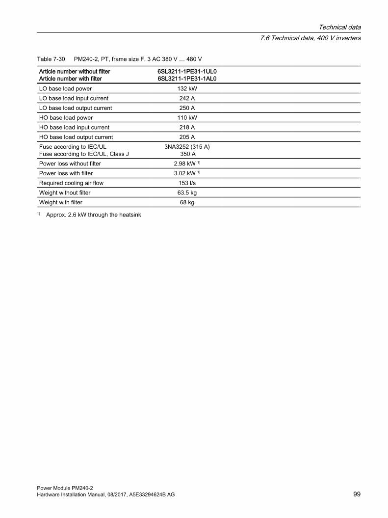
Table 7-30 PM240-2, PT, frame size F, 3 AC 380 V … 480 V
Article number without filterArticle number with filter
6SL3211-1PE31-1UL06SL3211-1PE31-1AL0
LO base load power 132 kW LO base load input current 242 A LO base load output current 250 A HO base load power 110 kW HO base load input current 218 A HO base load output current 205 A Fuse according to IEC/ULFuse according to IEC/UL, Class J
3NA3252 (315 A) 350 A
Power loss without filter 2.98 kW 1) Power loss with filter 3.02 kW 1) Required cooling air flow 153 l/s Weight without filter 63.5 kg Weight with filter 68 kg
1) Approx. 2.6 kW through the heatsink
Technical data7.6 Technical data, 400 V inverters
Power Module PM240-2Hardware Installation Manual, 08/2017, A5E33294624B AG 99
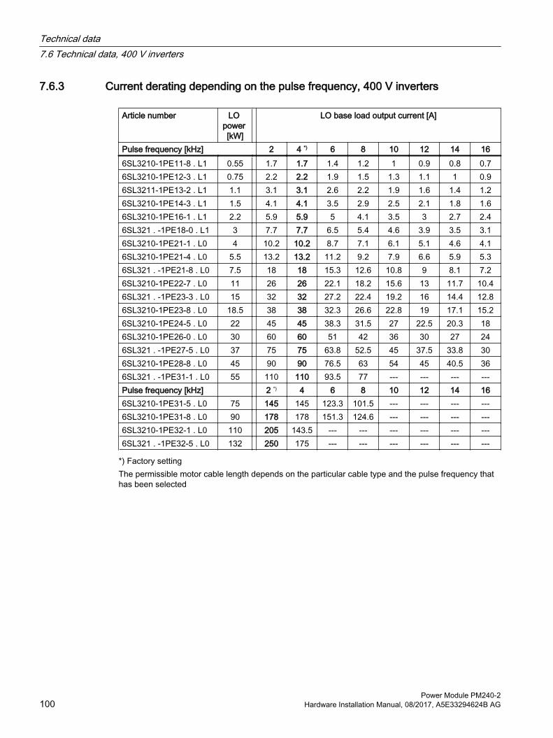
7.6.3 Current derating depending on the pulse frequency, 400 V inverters
Article number LO power [kW]
LO base load output current [A]
Pulse frequency [kHz] 2 4 *) 6 8 10 12 14 166SL3210-1PE11-8 . L1 0.55 1.7 1.7 1.4 1.2 1 0.9 0.8 0.76SL3210-1PE12-3 . L1 0.75 2.2 2.2 1.9 1.5 1.3 1.1 1 0.96SL3211-1PE13-2 . L1 1.1 3.1 3.1 2.6 2.2 1.9 1.6 1.4 1.26SL3210-1PE14-3 . L1 1.5 4.1 4.1 3.5 2.9 2.5 2.1 1.8 1.66SL3210-1PE16-1 . L1 2.2 5.9 5.9 5 4.1 3.5 3 2.7 2.46SL321 . -1PE18-0 . L1 3 7.7 7.7 6.5 5.4 4.6 3.9 3.5 3.16SL3210-1PE21-1 . L0 4 10.2 10.2 8.7 7.1 6.1 5.1 4.6 4.16SL3210-1PE21-4 . L0 5.5 13.2 13.2 11.2 9.2 7.9 6.6 5.9 5.36SL321 . -1PE21-8 . L0 7.5 18 18 15.3 12.6 10.8 9 8.1 7.26SL3210-1PE22-7 . L0 11 26 26 22.1 18.2 15.6 13 11.7 10.46SL321 . -1PE23-3 . L0 15 32 32 27.2 22.4 19.2 16 14.4 12.86SL3210-1PE23-8 . L0 18.5 38 38 32.3 26.6 22.8 19 17.1 15.26SL3210-1PE24-5 . L0 22 45 45 38.3 31.5 27 22.5 20.3 186SL3210-1PE26-0 . L0 30 60 60 51 42 36 30 27 246SL321 . -1PE27-5 . L0 37 75 75 63.8 52.5 45 37.5 33.8 306SL3210-1PE28-8 . L0 45 90 90 76.5 63 54 45 40.5 366SL321 . -1PE31-1 . L0 55 110 110 93.5 77 --- --- --- ---Pulse frequency [kHz] 2 *) 4 6 8 10 12 14 166SL3210-1PE31-5 . L0 75 145 145 123.3 101.5 --- --- --- ---6SL3210-1PE31-8 . L0 90 178 178 151.3 124.6 --- --- --- ---6SL3210-1PE32-1 . L0 110 205 143.5 --- --- --- --- --- ---6SL321 . -1PE32-5 . L0 132 250 175 --- --- --- --- --- ---
*) Factory settingThe permissible motor cable length depends on the particular cable type and the pulse frequency that has been selected
Technical data7.6 Technical data, 400 V inverters
Power Module PM240-2100 Hardware Installation Manual, 08/2017, A5E33294624B AG
7.7 Technical data, 690 V inverters
Motors for 690 V Power ModulesFor the 690 V Power Modules, induction motors are permissible in the range from 50 % … 150 % of the inverter power without any restrictions.
NoteMotors for inverter operation
Only use motors that are suitable for operation with inverters with a DC link.
For 690 V Power Modules, motors with a suitable insulation system for 690 V inverter operation are required (e.g. PREMIUM).
7.7.1 General data, 690 V inverters
Property VersionLine voltage ● for systems according to IEC: 3-ph. AC 500 V … 690 V ± 10% (in operation -20% < 1 min)
● for systems according to UL 3-ph. AC 500 V … 600 V ± 10% (in operation -20% < 1 min) filtered devices only with Slash Rating (600Y/347V AC)
Line supply configurations Grounded TN/TT line supplies or non-grounded IT line suppliesPermissible line supplies (Page 50)
Line impedance No restrictionsPower factor λ > 0.9 Output voltage 3-ph. AC 0 V … 0.95 x input voltage (max.)Input frequency 50 Hz … 60 Hz, ± 3 Hz Output frequency 0 … 550 Hz, depending on the control modeInrush current < LO base load input currentOvervoltage category ac‐cording to EN 61800-5-1
III for line supplies
Pulse frequency 2 kHz (factory setting), can be adjusted to 4 kHzIf you increase the pulse frequency, the inverter reduces the maximum output current.
Short-circuit current rating (SCCR) and branch protec‐tion
≤ 100 kA rms Branch protection and short-circuit strength according to UL and IEC (https://
support.industry.siemens.com/cs/ww/en/view/109479152)Braking methods DC braking, compound braking, dynamic braking with integrated braking chopperDegree of protection ac‐cording to EN 60529
IP20; must be installed in a control cabinet
Protection class according to EN 61800-5-1
The inverters are devices with protection class I
Touch protection accord‐ing to EN 50274
DGUV regulation 3 when used for the intended purpose
Cooling in compliance with EN 60146
Forced air cooling AF
Technical data7.7 Technical data, 690 V inverters
Power Module PM240-2Hardware Installation Manual, 08/2017, A5E33294624B AG 101

Dependent on the input voltage and output power
Technical data7.7 Technical data, 690 V inverters
Power Module PM240-2102 Hardware Installation Manual, 08/2017, A5E33294624B AG

7.7.2 Specific technical data, 690 V inverters
Table 7-31 PM240-2, IP20, frame size D, 500 V … 690 V 3 AC
Article No. - without filterArticle No. - with filter
6SL3210-1PH21-4UL0 6SL3210-1PH21-4AL0
6SL3210-1PH22-0UL0 6SL3210-1PH22 -0AL0
6SL3210-1PH22-3UL0 6SL3210-1PH22 -3AL0
LO base load power 11 kW 15 kW 18.5 kWLO base load input current 14 A 18 A 22 ALO base load output current 14 A 19 A 23 AHO base load power 7.5 kW 11 kW 15 kWHO base load input current 11 A 14 A 20 A HO base load output current 11 A 14 A 19 AFuse according to IEC/ULFuse according to IEC/UL, Class J
3NA3807-6 (20 A) 20 A
3NA3810-6 (25 A) 25 A
3NA3812-6 (32 A) 30 A
Power loss without filter 0.35 kW 0.44 kW 0.52 kWPower loss with filter 0.35 kW 0.45 kW 0.52 kWRequired cooling air flow 55 l/s 55 l/s 55 l/sWeight without filter 17 kg 17 kg 17 kgWeight with filter 18.5 kg 18.5 kg 18.5 kg
Table 7-32 PM240-2, IP20, frame size D, 500 V … 690 V 3 AC
Article No. - without filterArticle No. - with filter
6SL3210-1PH22-7UL0 6SL3210-1PH22-7AL0
6SL3210-1PH23-5UL0 6SL3210-1PH23 -5AL0
6SL3210-1PH24-2UL0 6SL3210-1PH24-2AL0
LO base load power 22 kW 30 kW 37 kWLO base load input current 25 A 33 A 40 ALO base load output current 27 A 35 A 42 AHO base load power 18.5 kW 22 kW 30 kWHO base load input current 24 A 28 A 36 A HO base load output current 23 A 27 A 35 ASiemens fuse according to IEC/ULFuse according to IEC/UL, Class J
3NA3817-6KJ (40 A)35 A
3NA3820-6KJ (50 A)45 A
33NA3822-6 (63 A)60 A
Power loss without filter 0.60 kW 0.77 kW 0.93 kWPower loss with filter 0.60 kW 0.78 kW 0.94 kWRequired cooling air flow 55 l/s 55 l/s 55 l/sWeight without filter 17 kg 17 kg 17 kgWeight with filter 18.5 kg 18.5 kg 18.5 kg
Technical data7.7 Technical data, 690 V inverters
Power Module PM240-2Hardware Installation Manual, 08/2017, A5E33294624B AG 103

Table 7-33 PM240-2, PT, frame size D, 500 V to 690 V 3 AC
Article No. without filterArticle No. with filter
6SL3211-1PH24-2UL0 6SL3211-1PH24-2AL0
LO base load power 37 kW LO base load input current 40 A LO base load output current 42 A HO base load power 30 kW HO base load input current 36 A HO base load output current 35 A Fuse according to IECFuse according to UL, class J
33NA3822-6 (63 A)60 A
Power loss without filter 0.93 kW 1) Power loss with filter 0.94 kW 1) Required cooling air flow 55 l/s Weight without filter 20.5 kg Weight with filter 22.5 kg
1) approx. 0.8 kW through the heatsink
Table 7-34 PM240-2, IP20, frame size E, 500 V … 690 V 3 AC
Article No. - without filterArticle No. - with filter
6SL3210-1PH25-2UL0 6SL3210-1PH25-2AL0
6SL3210-1PH26-2UL0 6SL3210-1PH26-2AL0
LO base load power 45 kW 55 kW LO base load input current 50 A 59 A LO base load output current 52 A 62 A HO base load power 37 kW 45 kW HO base load input current 44 A 54 A HO base load output current 42 A 52 A Siemens fuse according to IEC/ULFuse according to IEC/UL, Class J
3NA3824-6 (80A)80 A
3NA3824-6 (80A)80 A
Power loss without filter 1.07 kW 1.30 kW Power loss with filter 1.08 kW 1.31 kW Required cooling air flow 83 l/s 83 l/s Weight without filter 26 kg 26 kg Weight with filter 28 kg 28 kg
Technical data7.7 Technical data, 690 V inverters
Power Module PM240-2104 Hardware Installation Manual, 08/2017, A5E33294624B AG

Table 7-35 PM240-2, PT, frame size E, 500 V to 690 V 3 AC
Article No. without filterArticle No. with filter
6SL3211-1PH26-2UL0 6SL3211-1PH26-2AL0
LO base load power 55 kW LO base load input current 59 A LO base load output current 62 A HO base load power 45 kW HO base load input current 54 A HO base load output current 52 A Fuse according to IECFuse according to UL, class J
3NA3824-6 (80A)80 A
Power loss without filter 1.30 kW 1) Power loss with filter 1.31 kW 1) Required cooling air flow 83 l/s Weight without filter 31 kg Weight with filter 32.5 kg
1) approx. 1.2 kW through the heatsink
Table 7-36 PM240-2, IP20, frame size F, 500 V … 690 V 3 AC
Article No. - without filterArticle No. - with filter
6SL3210-1PH28-0UL0 6SL3210-1PH28-0AL0
6SL3210-1PH31-0UL0 6SL3210-1PH31-0AL0
6SL3210-1PH31-2UL0 6SL3210-1PH31-2AL0
LO base load power 75 kW 90 kW 110 kWLO base load input current 78 A 97 A 111 ALO base load output current 80 A 100 A 115 AHO base load power 55 kW 75 kW 90 kWHO base load input current 66 A 85 A 106 A HO base load output current 62 A 80 A 100 ASiemens fuse according to IEC/ULFuse according to IEC/UL, Class J
3NA3830-6 (100 A) 100 A
3NA3132-6 (125 A) 125 A
3NA3136-6 (160 A) 150 A
Power loss without filter 1.37 kW 1.74 kW 1.95 kWPower loss with filter 1.38 kW 1.76 kW 1.97 kWRequired cooling air flow 153 l/s 153 l/s 153 l/sWeight without filter 60 kg 60 kg 60 kgWeight with filter 64 kg 64 kg 64 kg
Technical data7.7 Technical data, 690 V inverters
Power Module PM240-2Hardware Installation Manual, 08/2017, A5E33294624B AG 105
Table 7-37 PM240-2, IP20, frame size F, 500 V … 690 V 3 AC
Article No. - without filterArticle No. - with filter
6SL3210-1PH31-4UL06SL3210-1PH31-4AL0
LO base load power 132 kW LO base load input current 137 A LO base load output current 142 A HO base load power 110 kW HO base load input current 122 A HO base load output current 115 A Siemens fuse according to IEC/ULFuse according to IEC/UL, Class J
3NA3140-6 (200 A) 200 A
Power loss without filter 2.48 kW Power loss with filter 2.51 kW Required cooling air flow 153 l/s Weight without filter 60 kg Weight with filter 64 kg
Table 7-38 PM240-2, PT, frame size F, 500 V to 690 V 3 AC
Article No. without filterArticle No. with filter
6SL3211-1PH31-4UL06SL3211-1PH31-4AL0
LO base load power 132 kW LO base load input current 137 A LO base load output current 142 A HO base load power 110 kW HO base load input current 122 A HO base load output current 115 A Fuse according to IECFuse according to UL, class J
3NA3140-6 (200 A) 200 A
Power loss without filter 2.48 kW 1) Power loss with filter 2.51 kW 1) Required cooling air flow 153 l/s Weight without filter 64 kg Weight with filter 69 kg
1) approx. 2.3 kW through the heatsink
Technical data7.7 Technical data, 690 V inverters
Power Module PM240-2106 Hardware Installation Manual, 08/2017, A5E33294624B AG

7.7.3 Current derating depending on the pulse frequency, 690 V inverters
Article number LO power [kW] LO base load output current [A] Pulse frequency [kHz] 2 *) 46SL3210-1PH21-4 . L0 11 14 8.46SL3210-1PH22-0 . L0 15 19 11.46SL3210-1PH22-3 . L0 18.5 23 13.86SL3210-1PH22-7 . L0 22 27 16.26SL3210-1PH23-5 . L0 30 35 216SL321 . -1PH24-2 . L0 37 42 25.26SL3210-1PH25-2 . L0 45 52 31.26SL321 . -1PH26-2 . L0 55 62 37.26SL3210-1PH28-0 . L0 75 80 486SL3210-1PH31-0 . L0 90 100 606SL3210-1PH31-2 . L0 110 115 696SL321 . -1PH31-4 . L0 132 142 85.2
*) Factory settingThe permissible motor cable length depends on the particular cable type and the pulse frequency that has been selected
Technical data7.7 Technical data, 690 V inverters
Power Module PM240-2Hardware Installation Manual, 08/2017, A5E33294624B AG 107
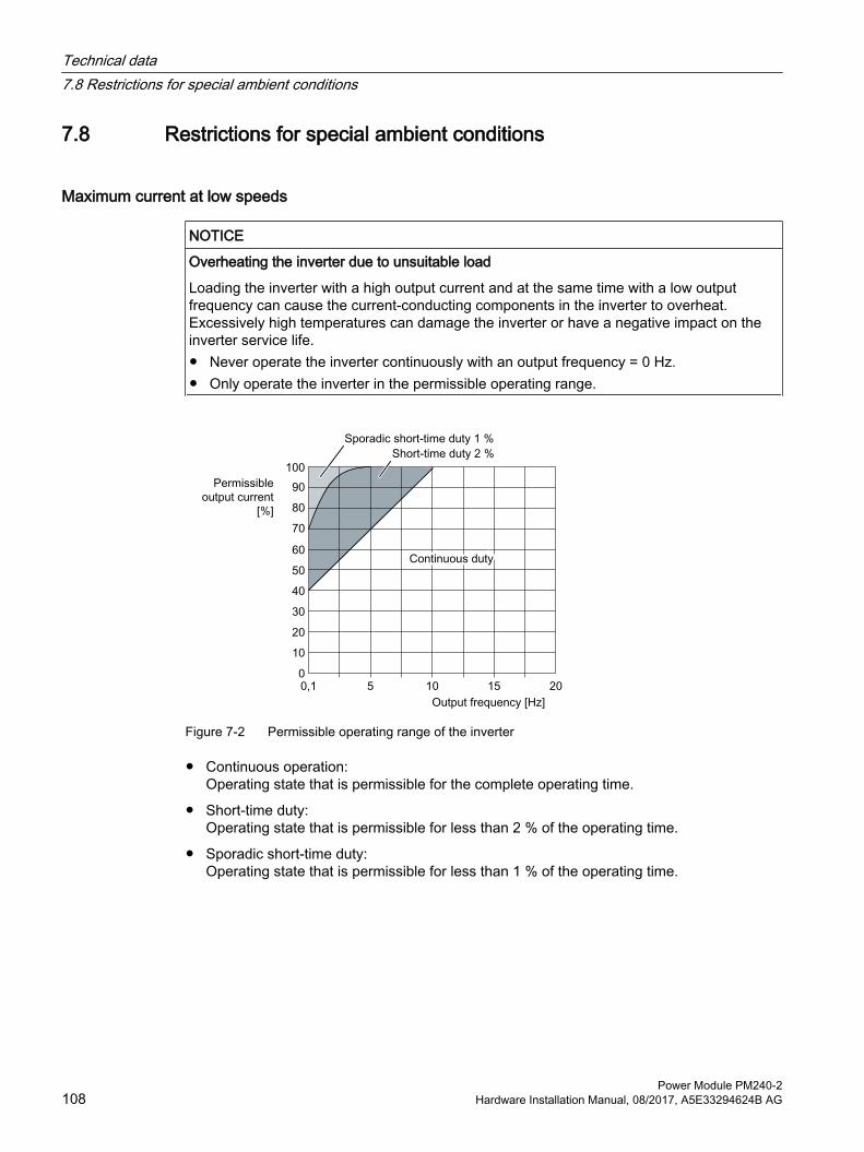
7.8 Restrictions for special ambient conditions
Maximum current at low speeds
NOTICE
Overheating the inverter due to unsuitable load
Loading the inverter with a high output current and at the same time with a low output frequency can cause the current-conducting components in the inverter to overheat. Excessively high temperatures can damage the inverter or have a negative impact on the inverter service life.● Never operate the inverter continuously with an output frequency = 0 Hz.● Only operate the inverter in the permissible operating range.
Figure 7-2 Permissible operating range of the inverter
● Continuous operation: Operating state that is permissible for the complete operating time.
● Short-time duty:Operating state that is permissible for less than 2 % of the operating time.
● Sporadic short-time duty:Operating state that is permissible for less than 1 % of the operating time.
Technical data7.8 Restrictions for special ambient conditions
Power Module PM240-2108 Hardware Installation Manual, 08/2017, A5E33294624B AG

Current reduction as a function of the installation altitude and ambient temperatureAt installation altitudes above 1000 m and temperatures higher than 40° C (low overload) or 50° C (high overload), the inverter output current is reduced. The following tables contain the details.
Table 7-39 Maximum permitted output current for loading according to LO
Installation altitude [m]
up to
Ambient temperature [°C]20 25 30 35 40 45 50 55 60
Output current in [%] when loading to LO
1000 100 93 85 76 661500 100 95 88 81 72 632000 100 97 90 83 77 68 592500 100 98 91 85 79 72 64 563000 100 98 92 86 80 74 68 60 533500 98 92 86 81 75 69 64 57 504000 91 86 81 75 70 65 60 53 46
Table 7-40 Maximum permitted output current when loading according to HO
Installation altitude [m]
up to
Ambient temperature [°C]20 25 30 35 40 45 50 55 60
Output current in [%] when loading to HO
1000 100 87 741500 100 95 83 702000 100 99 95 90 78 672500 100 98 94 89 85 74 633000 100 96 92 88 84 80 70 593500 98 94 90 86 83 79 75 65 564000 91 88 84 81 77 74 70 61 52
Also observe the maximum permissible ambient operating temperatures for the Control Unit and possibly the Operator Panel.
Permissible line supplies dependent on the installation altitude● For installation altitudes ≤ 2000 m above sea level, it is permissible to connect the inverter
to any of the line supplies that are specified for it.
Technical data7.8 Restrictions for special ambient conditions
Power Module PM240-2Hardware Installation Manual, 08/2017, A5E33294624B AG 109

● For installation altitudes 2000 m ... 4000 m above sea level, the following applies:
– Connection to a TN line system with grounded neutral point is permissible.
– TN systems with grounded line conductor are not permitted.
– The TN line system with grounded neutral point can also be supplied using an isolation transformer.
– The phase-to-phase voltage does not have to be reduced.
NoteUsing Power Modules connected to TN line supplies with voltages ≥ 600 V for installation altitudes 2000 m … 4000 m
For voltages ≥ 600 V, the TN line supply must have a grounded neutral point established using an isolating transformer.
Technical data7.8 Restrictions for special ambient conditions
Power Module PM240-2110 Hardware Installation Manual, 08/2017, A5E33294624B AG
7.9 Electromagnetic compatibility of variable-speed drivesEMC (electromagnetic compatibility) means that the devices function satisfactorily without interfering with other devices and without being disrupted by other devices. EMC applies when the emitted interference (emission level) and the interference immunity are matched with each other.
The product standard IEC/EN 61800-3 describes the EMC requirements placed on "Variable-speed drive systems".
A variable-speed drive system (or Power Drive System PDS) consists of the inverter as well as the associated electric motors and encoders including the connecting cables.
The driven machine is not part of the drive system.
NotePDS as component of machines or systems
When you install PDS into machines or systems, additional measures may be required so that the product standards of these machines or systems is complied with. The machine or system builder is responsible for taking these measures.
Environments and categories
EnvironmentsIEC/EN 61800-3 makes a distinction between the "first environment" and "second environment" - and defines different requirements for these environments.
● First environment: Residential buildings or locations at which the PDS is directly connected to a public low-voltage supply without intermediate transformer.
● Second environment: All industrial plant/systems or locations that are connected to the public grid through their own, dedicated transformer.
CategoriesIEC/EN 61800-3 makes a distinction between four drive system categories:
● Category C1: Drive systems for rated voltages < 1000 V for unrestricted use in the "first environment"
● Category C2: Stationary PDS for rated voltages < 1000 V for operation in the "second environment". Appropriately qualified personnel are required to install the PDS. An appropriately trained and qualified person has the necessary experience for installing and commissioning a PDS, including the associated EMC aspects.Additional measures are required for operation in the "first environment".
Technical data7.9 Electromagnetic compatibility of variable-speed drives
Power Module PM240-2Hardware Installation Manual, 08/2017, A5E33294624B AG 111

● Category C3: PDS for rated voltages < 1000 V - only for operation in the "second environment".
● Category C4: PDS for IT line supplies for operation in complex systems in the "second environment". An EMC plan is required.
7.9.1 Inverter applications
Inverters involve equipment used on a professional basis, deployed in certain areas of business and industry - and are not operated in the general public domain.
For an EMC-compliant installation, observe the information provided in the Configuration manual: EMC installation guideline (http://support.automation.siemens.com/WW/view/en/60612658).
The devices described there are intended for operation in the first and second environments. Conditions for operation in the respective environment are subsequently listed.
7.9.1.1 Operation in the Second Environment
Interference immunity You do not have to take any additional measures regarding interference immunity.
Interference emission - operation in the second environment, Category C2The drive system must comply with the following conditions in order to comply with the limit values of the second environment, Category C2:
● The drive system is installed by appropriately qualified personnel in compliance with EMC regulations - and the installation notes provided in the manual.
● You use a shielded motor cable with low capacitance.
● The pulse frequency is not higher than the value set in the factory.
Technical data7.9 Electromagnetic compatibility of variable-speed drives
Power Module PM240-2112 Hardware Installation Manual, 08/2017, A5E33294624B AG
● The drive system is connected to a TN or TT line supply.
● You comply with the permissible motor cable length. Length of the motor cable (Page 59).
● The inverters are equipped with a Category C2 line filter (internal or external).
– 200 V inverter, frame size FSA … FSC Inverters with integrated filter are suitable for operation in the Second Environment, Category C2.
– 200 V inverter, frame size FSD … FSF The inverters require an external filter, Category C2
– 400 V inverterInverters with integrated filter are suitable for operation in the Second Environment, Category C2.
– 690 V inverterInverters of frame sizes FSD and FSE with integrated filter are suitable for operation in the Second Environment, Category C2. Inverters of frame size FSF with integrated filter are suitable for operation in the Second Environment, Category C3.
With the external filters, from Section Line filter (Page 129), the inverters without integrated filter comply with the requirements of the Second Environment, Category C2 with reference to interference emission.If you use inverters without integrated filter or a filter other than those mentioned above, then you are responsible for verifying that the interference emission is limited. You can use a dedicated radio interference suppression filter for each inverter - or a common filter for several inverters.
Interference emission - operation in the second environment, Category C4 When connected to IT line supplies, only filtered inverters are permissible. Use external filters without capacitors with respect to ground to limit symmetrical interference emission. When necessary, contact one of our Solution Partners (https://www.automation.siemens.com/solutionpartner/partnerfinder/Home/Index?country=DE&program=1&technology=19&lang=en).
Technical data7.9 Electromagnetic compatibility of variable-speed drives
Power Module PM240-2Hardware Installation Manual, 08/2017, A5E33294624B AG 113

7.9.1.2 Operation in the First Environment
Interference immunity You do not have to take any additional measures regarding interference immunity.
Interference emission - operation in the first environment, Category C2In order that you may operate the drive system in the first environment, Category C2, then in addition to the requirements for use in the second environment, you must also observe the limit values related to harmonic currents.
NoteMaintaining the limit values for harmonic currents
With respect to the compliance with limits for harmonic currents, the EMC product standard EN61800‑3 for PDS refers to compliance with standards EN 61000‑3‑2 and EN 61000‑3‑12.
Inverter with an LO base load power ≤ 1 kW:It cannot be guaranteed that the limit values are complied with corresponding to IEC 61000-3-2. The installation person/company or company operating the professionally used device must obtain authorization from the grid operator to connect the device regarding the harmonic currents.
Typical harmonic currents (Page 115)
Inverters with an LO base load input current ≤ 16 A:These devices are not subject to any limit values, and as a consequence can be connected to the public low-voltage grid without any prior consultation.
Inverters with an LO base load input current > 16 A and ≤ 75 AThe drive system is in compliance with IEC/EN 61000-3-12 under the following preconditions:
● FSC Power Module, input voltage 3 AC 200 … 240 V: You use a 3% or 4% line reactor.
● FSD Power Module, input voltage 3 AC 200 … 240 V: A line reactor is not required
● FSB/FSC Power Module, input voltage 3 AC 380 … 480 V: You use a 3% or 4% line reactor.
Technical data7.9 Electromagnetic compatibility of variable-speed drives
Power Module PM240-2114 Hardware Installation Manual, 08/2017, A5E33294624B AG

● Power Module FSD, input voltage 380 … 480 V 3 AC: A line reactor is not required
NoteLine reactor
Contact our Solution Partners (https://www.automation.siemens.com/solutionpartner/partnerfinder/Home/Index?country=DE&program=1&technology=19&lang=en) for a line reactor.
● Short-circuit power SSC at the connection point of the customer's system to the public grid, is greater than or equal to the value according to the following formula: SSC ≥ 120 x √3 x Vin x LO base load input currentExample: FSD inverter, 400 V, input current, 70 A:SSC ≥ 120 x √3 x 400 V x 70 AThis corresponds to a low-voltage transformer with an apparent power rating of 300 kVA … 400 kVA with VK = 4% … 6%The installation company or company operating the equipment is responsible for ensuring that this equipment is only connected at a connection point with an appropriate short-circuit power (fault level).
If these preconditions do not apply, then the installation company or company operating the device must obtain authorization from the grid operator to connect the device regarding the harmonic currents.
Typical harmonic currents (Page 115)
Inverters with an LO base load current > 75A
There are no standard-related requirements for installing devices such as these. However, we recommend that the grid operator is informed when such a device is connected.400 V inverters conform to EN 61000‑3‑12.
7.9.2 Typical harmonic currents
Table 7-41 Typical harmonic currents (%) of the inverter
Inverter Harmonic number5th 7th 11th 13th 17th 19th 23rd 25th
FSA … FSC, 200 V, 400 V 1) 54 39 11 5.5 5 3 2 2FSD … FSF, 200 V 2) 28 14 8 6 5 4 3 3FSD … FSF, 400 V 2) 37 21 7 5 4 3 3 2FSD … FSF, 690 V 2) 34 18 8 5 4 3 3 2
1) Values relative to the LO input current for VK 1% 2) Values relative to the LO input current
Technical data7.9 Electromagnetic compatibility of variable-speed drives
Power Module PM240-2Hardware Installation Manual, 08/2017, A5E33294624B AG 115

7.9.3 EMC limit values in South KoreaThe following statements apply for filtered 400 V inverters, frame sizes FSD ... FSF.
All other inverters do not comply with the limit values.
The EMC limit values to be observed for Korea correspond to the limit values of the EMC product standard for variable-speed electric drives EN 61800-3 of category C2 or the limit value class A, Group 1 to KN11.
By implementing appropriate additional measures, the limit values according to category C2 or limit value class A, Group 1, are observed.
Additional measures, such as the use of an additional RFI suppression filter (EMC filter), may be necessary.
In addition, measures for EMC-compliant configuration of the plant or system are described in detail in this manual and in the Configuration manualEMC installation guideline (http://support.automation.siemens.com/WW/view/en/60612658).
The final statement on compliance with the applicable standard is given by the respective label attached to the individual device.
Technical data7.9 Electromagnetic compatibility of variable-speed drives
Power Module PM240-2116 Hardware Installation Manual, 08/2017, A5E33294624B AG

Spare parts 8Continuous development within the scope of product maintenance
Inverter components are being continuously developed within the scope of product maintenance. Product maintenance includes, for example, measures to increase the ruggedness or hardware changes which become necessary as components are discontinued.
These further developments are "spare parts-compatible" and do not change the article number.
In the scope of such spare parts-compatible ongoing development, plug connector or connection positions are sometimes slightly modified. This does not cause any problems when the components are properly used. Please take this fact into consideration in special installation situations (e.g. allow sufficient reserve regarding the cable length).
Spare parts for frame sizes FSA … FSC
Article numberFSA FSB FSC
Accessory kit IP20*)
A5E33860501A A5E33879111A A5E33879131A
Accessory kit PT*)
A5E03396337 A5E03395273 A5E03343234
*) Included in the scope of delivery of the inverterCan be ordered through the Siemens Repair Center
Spare parts for frame sizes FSD … FSF
Article numberFSD FSE FSF
Set of small compo‐nents
6SL3200-0SK08-0AA0 6SL3200-0SK08-0AA0 6SL3200-0SK08-0AA0
Mechanical kit 6SL3200-0SM13-0AA0 6SL3200-0SM14-0AA0 6SL3200-0SM15-0AA0Fan kit, IP20 devices 6SL3200-0SF25-0AA0 6SL3200-0SF27-0AA0 6SL3200-0SF28-0AA0Fan kit, PT devices 6SL3200-0SF25-0AA0 6SL3200-0SF27-0AA0 6SL3200-0SF28-0AA0Accessory kit / shield connection kit
6SL3262-1AD01-0DA0 6SL3262-1AE01-0DA0 6SL3262-1AF01-0DA0
Power Module PM240-2Hardware Installation Manual, 08/2017, A5E33294624B AG 117

Spare parts
Power Module PM240-2118 Hardware Installation Manual, 08/2017, A5E33294624B AG

Accessories 9Which components are available?
● Accessory kit / shield connection kit (includes the upper shield plate)
● Mounting frames for PT Power Modules
● Mounting grips for PT Power Modules - frame sizes FSD ... FSF
● Line reactors for frame sizes FSA … FSCLine reactors are not required for frame sizes FSD … FSF.
● External line filters, Class B for frame sizes FSA … FSC.No Class B filters are available for frame sizes FSD … FSF.
● Braking resistors
● Brake Relay or Safe Brake Relay for controlling a motor holding brake
● Output reactors
● Voltage limiter and du/dt filter
Connection componentsConnection overview for the electrical components Connection overview (Page 55).
Power Module PM240-2Hardware Installation Manual, 08/2017, A5E33294624B AG 119
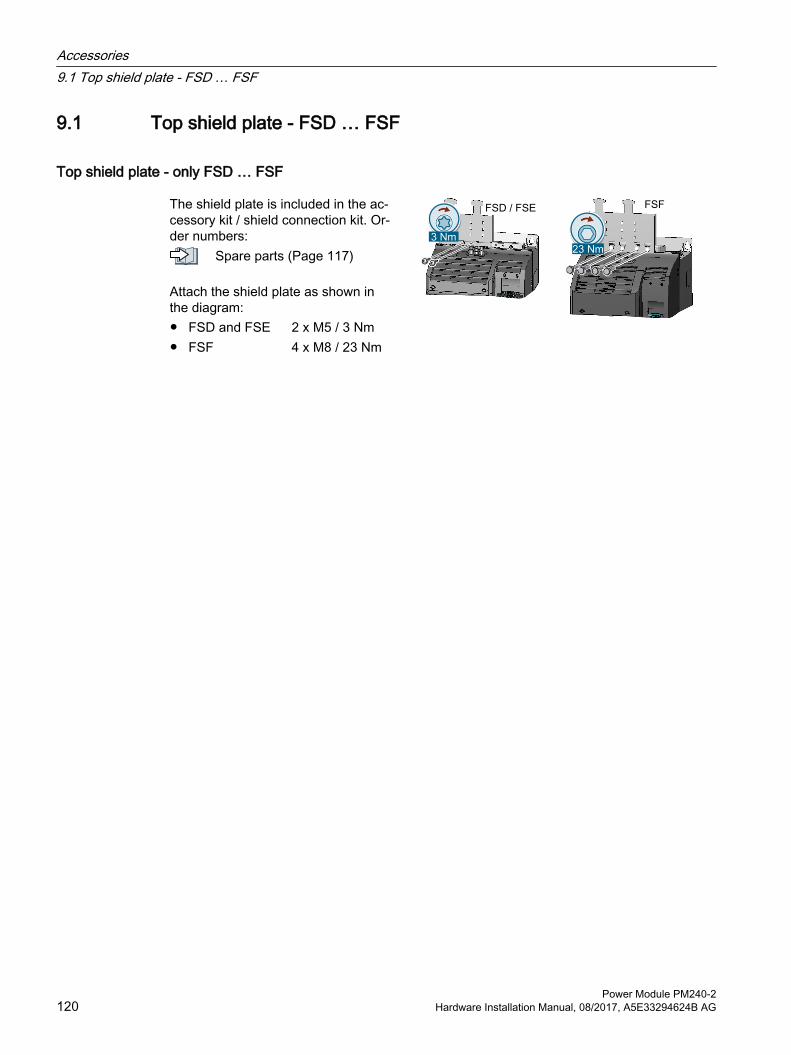
9.1 Top shield plate - FSD … FSF
Top shield plate - only FSD … FSF
The shield plate is included in the ac‐cessory kit / shield connection kit. Or‐der numbers:
Spare parts (Page 117)
Attach the shield plate as shown in the diagram:
● FSD and FSE● FSF
2 x M5 / 3 Nm4 x M8 / 23 Nm
Accessories9.1 Top shield plate - FSD … FSF
Power Module PM240-2120 Hardware Installation Manual, 08/2017, A5E33294624B AG

9.2 Mounting frames for PT power modules
Order numbers for mounting frames● FSA: 6SL3260-6AA00-0DA0
● FSB: 6SL3260-6AB00-0DA0
● FSC: 6SL3260-6AC00-0DA0
● FSD: 6SL3200-0SM17-0AA0
● FSE: 6SL3200-0SM18-0AA0
● FSF: 6SL3200-0SM20-0AA0
All of the necessary nuts and seals are included in the scope of delivery.
Accessories9.2 Mounting frames for PT power modules
Power Module PM240-2Hardware Installation Manual, 08/2017, A5E33294624B AG 121
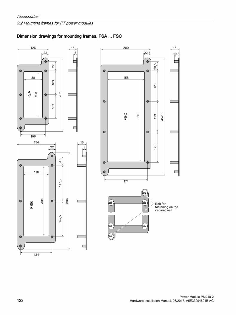
Dimension drawings for mounting frames, FSA ... FSC
Accessories9.2 Mounting frames for PT power modules
Power Module PM240-2122 Hardware Installation Manual, 08/2017, A5E33294624B AG

Dimension drawings for mounting frames, FSD ... FSF
Accessories9.2 Mounting frames for PT power modules
Power Module PM240-2Hardware Installation Manual, 08/2017, A5E33294624B AG 123

9.2.1 Mounting instructions with mounting frame
ProcedureProceed as follows to correctly mount the Power Module with the mounting frame:
1. Prepare a cutout and holes in the control cabinet panel for the mounting frame corresponding to the dimension drawing.
2. Insert the mounting frame from the rear of the control cabinet through the corresponding holes and fix it in place at the fixing screws for the control cabinet panel; tighten the two / four nuts by hand.
3. Attach the seal to the inner side of the control cabinet (frame sizes FSA ... FSC only).
4. Insert the Power Module and tighten the screws by hand.
5. Mount the Power Module.
6. Finally, tighten the screws with the following torques.
– M5 screws: 3.5 Nm
– M6 screws: 5.9 Nm
You have correctly installed the Power Module.
Figure 9-1 Installation instructions for the PT Power Modules with the optional mounting frame
Accessories9.2 Mounting frames for PT power modules
Power Module PM240-2124 Hardware Installation Manual, 08/2017, A5E33294624B AG

9.3 Mounting grips for PT Power ModulesMounting grips can be ordered for the PT Power Modules FSD ... FSF. The mounting grips enable the installation of the Power Module without hoisting gear.
Install the four hoisting grips as shown in the following image.
Article number: 6SL3200-0SM22-0AA0
Accessories9.3 Mounting grips for PT Power Modules
Power Module PM240-2Hardware Installation Manual, 08/2017, A5E33294624B AG 125

9.4 Line reactorA line reactor protects the inverter when connected to dirty line supplies (line supply environment). A line reactor supports the overvoltage protection, smooths the harmonics in the line supply and buffers commutation dips.
Mounting position
Clearances to other devicesKeep shaded areas free of any devices and components.
Figure 9-2 Clearances between the line reactors and other devices, examples for space-saving installation
Accessories9.4 Line reactor
Power Module PM240-2126 Hardware Installation Manual, 08/2017, A5E33294624B AG

Dimensions [mm] and drilling patterns
Article number 6SL3203‑0CE13‑2AA0
Article number 6SL3203‑0CE21‑0AA0
Article number 6SL3203‑0CE21‑8AA0
Article number 6SL3203‑0CE23‑8AA0
Mount the line reactor using M5 screws, nuts and washers. Tightening torque: 6 Nm
Assignment of line reactor to inverter: Table Assignment table (Page 128)
Accessories9.4 Line reactor
Power Module PM240-2Hardware Installation Manual, 08/2017, A5E33294624B AG 127

Table 9-1 Technical data of the line reactors
Article number Induc‐tance[mH]
Line/load connection PE connection Weight[kg][mm2 / nM] [AWG / lbf in] [mm2 / lbf in]
6SL3203-0CE13-2AA0 2.5 2.5 / 0.8 14 / 7 M4 [3 / 26.5] 1.16SL3203-0CE21-0AA0 1 6 / 1.8 10 / 15.9 M4 [3 / 26.5] 2.16SL3203-0CE21-8AA0 0.5 6 / 1.8 10 / 15.9 M5 [5 / 44.3] 2.956SL3203-0CE23-8AA0 0.3 16 / 4 6 / 34.5 M5 [5 / 44.3] 7.80
The line reactors are designed to IP20 degree of protection.
Table 9-2 Assignment table
Line reactors Power Module, 400 V Power Module, 200 V6SL3203-0CE13-2AA0 6SL3210-1PE11-8 . L1,
6SL3210-1PE12-3 . L16SL3210-1PE13-2 . L1
FSA 6SL3210-1PB13-0 . L0, 6SL321 . -1PB13-8 . L0
FSA
6SL3203-0CE21-0AA0 6SL3210-1PE14-3 . L1, 6SL321 . -1PE16-1 . L16SL321 . -1PE18-0 . L1
FSA 6SL3210-1PB15-5 . L0, 6SL3210-1PB17-4 . L06SL321 . -1PB21-0 . L0
FSB
6SL3203-0CE21-8AA0 6SL3210-1PE21-1 . L0, 6SL3210-1PE21-4 . L06SL321 . -1PE21-8 . L0
FSB 6SL3210-1PB21-4 . L06SL321 . -1PB21-8 . L0
FSC
6SL3203-0CE23-8AA0 6SL3210-1PE22-7 . L0, 6SL321 . -1PE23-3 . L0
FSC 6SL321 . -1PC22-2 . L06SL3210-1PC22-8 . L0
FSC
Line reactors for 1 AC 200 V For inverters with 1 AC 200 V connection, rather than the line reactors listed above, you can also deploy the following or similar products:
● FSA:NKE 10 / 2.93 (Block company)
● FSBNKE 25 / 1.17 (Block company)
● FSCNKE 35 / 1.46 (Block company)
The technical properties and statements made by the manufacturer apply.
Accessories9.4 Line reactor
Power Module PM240-2128 Hardware Installation Manual, 08/2017, A5E33294624B AG
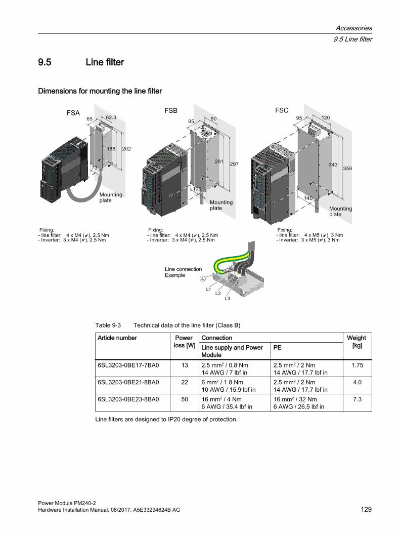
9.5 Line filter
Dimensions for mounting the line filter
Table 9-3 Technical data of the line filter (Class B)
Article number Power loss [W]
Connection Weight [kg]Line supply and Power
ModulePE
6SL3203-0BE17-7BA0 13 2.5 mm2 / 0.8 Nm14 AWG / 7 lbf in
2.5 mm2 / 2 Nm14 AWG / 17.7 lbf in
1.75
6SL3203-0BE21-8BA0 22 6 mm2 / 1.8 Nm10 AWG / 15.9 lbf in
2.5 mm2 / 2 Nm14 AWG / 17.7 lbf in
4.0
6SL3203-0BE23-8BA0 50 16 mm2 / 4 Nm6 AWG / 35.4 lbf in
16 mm2 / 32 Nm6 AWG / 26.5 lbf in
7.3
Line filters are designed to IP20 degree of protection.
Accessories9.5 Line filter
Power Module PM240-2Hardware Installation Manual, 08/2017, A5E33294624B AG 129

Table 9-4 Assignment table
Power Module, 400 V Line filter (Class B)Frame size Article number Power Article numberFSA 6SL3210-1PE11-8UL1
6SL3210-1PE12-3UL16SL3210-1PE13-2UL16SL3210-1PE14-3UL16SL3210-1PE16-1UL16SL321 . -1PE18-0UL1
0.550.751.11.52.23.0
6SL3203-0BE17-7BA0
FSB 6SL3210-1PE21-1UL06SL3210-1PE21-4UL06SL321 . -1PE21-8UL0
4.05.57.5
6SL3203-0BE21-8BA0
FSC 6SL3210-1PE22-7UL06SL321 . -1PE23-3UL0
1115
6SL3203-0BE23-8BA0
Accessories9.5 Line filter
Power Module PM240-2130 Hardware Installation Manual, 08/2017, A5E33294624B AG
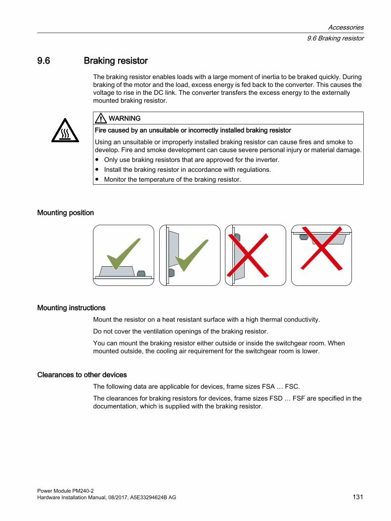
9.6 Braking resistorThe braking resistor enables loads with a large moment of inertia to be braked quickly. During braking of the motor and the load, excess energy is fed back to the converter. This causes the voltage to rise in the DC link. The converter transfers the excess energy to the externally mounted braking resistor.
WARNING
Fire caused by an unsuitable or incorrectly installed braking resistor
Using an unsuitable or improperly installed braking resistor can cause fires and smoke to develop. Fire and smoke development can cause severe personal injury or material damage.● Only use braking resistors that are approved for the inverter.● Install the braking resistor in accordance with regulations.● Monitor the temperature of the braking resistor.
Mounting position
Mounting instructionsMount the resistor on a heat resistant surface with a high thermal conductivity.
Do not cover the ventilation openings of the braking resistor.
You can mount the braking resistor either outside or inside the switchgear room. When mounted outside, the cooling air requirement for the switchgear room is lower.
Clearances to other devicesThe following data are applicable for devices, frame sizes FSA … FSC.
The clearances for braking resistors for devices, frame sizes FSD … FSF are specified in the documentation, which is supplied with the braking resistor.
Accessories9.6 Braking resistor
Power Module PM240-2Hardware Installation Manual, 08/2017, A5E33294624B AG 131

Figure 9-3 Minimum clearances for the braking resistor when mounting on a flat surface and for wall/panel mounting
Keep shaded areas free of any devices and components.
Dimensions and drilling patterns
Figure 9-4 Braking resistor
Accessories9.6 Braking resistor
Power Module PM240-2132 Hardware Installation Manual, 08/2017, A5E33294624B AG

Table 9-5 Dimensions and weights
Article number Overall dimensions [mm] Drilling dimensions [mm]
Fixing/torque Weight [kg]
Inverter frame size
W H D b hfor 200 V invertersJJY:023146720008 105 295 100 72 266 M4 / 3 Nm 1.5 FSA JJY:023151720007 105 345 100 72 316 M4 / 3 Nm 1.8 FSBJJY:02 3163720018 175 345 100 142 316 M4 / 3 Nm 2.7 FSCJJY:023433720001 250 490 140 217 460 M5 / 6 Nm 6.2 FSCJJY:023422620002 220 470 180 187 430 M5 / 6 Nm 7 FSDJJY:023423320001 220 560 180 187 500 M5 / 6 Nm 8.5 FSEJJY:023434020003 350 630 180 317 570 M5 / 6 Nm 13.5 FSFfor 400 V inverters6SL3201-0BE14-3AA0 105 295 100 72 266 M4 / 3 Nm 1.5 FSA6SL3201-0BE21-0AA0 105 345 100 72 316 M4 / 3 Nm 1.8 FSA6SL3201-0BE21-8AA0 175 345 100 142 316 M4 / 3 Nm 2.7 FSB6SL3201-0BE23-8AA0 250 490 140 217 460 M5 / 6 Nm 6.2 FSCJJY:023422620001 220 470 180 187 430 M5 / 6 Nm 7 FSDJJY:023424020001 220 610 180 187 570 M5 / 6 Nm 9.5 FSDJJY:023434020001 350 630 180 317 570 M5 / 6 Nm 13.5 FSEJJY:023454020001*) • JJY:023422620001 ∥• JJY:023434020001
220350
470630
180180
187317
430570
M5 / 6 NmM5 / 6 Nm
713.5
FSF(FSD)(FSE)
JJY:023464020001*) • JJY:023434020001 ∥• JJY:023434020001
350350
630630
180180
317317
570570
M5 / 6 NmM5 / 6 Nm
13.513.5
FSF(FSE)(FSE)
for 690 V invertersJJY:023424020002 220 610 180 187 570 M5 / 6 Nm 9.5 FSDJJY:023434020002 350 630 180 317 570 M5 / 6 Nm 13.5 FSEJJY:023464020002*)
• JJY:023434020002 ∥• JJY:023434020002
350350
630630
180180
317317
570570
M5 / 6 NmM5 / 6 Nm
13.513.5
FSF(FSE)(FSE)
Use the screws, nuts and washers when fixing the braking resistors*) This braking resistor comprises two components, which must be connected in parallel on the plant/system side
Accessories9.6 Braking resistor
Power Module PM240-2Hardware Installation Manual, 08/2017, A5E33294624B AG 133

9.6.1 Connecting a braking resistorThe following figure shows a connection overview of the braking resistor on the inverter.
Figure 9-5 Connecting a braking resistor with temperature monitoring via digital input DI 3
Some braking resistors have an integrated connection cable for the power connections (R1/R2) on the inverter. Thus, the length and cross-section of the connection cable are given.
For braking resistors without integrated connection cable, the maximum cable length is 10 m. The required conductor cross-sections are contained in the following tables.
The conductor cross-sections for the temperature monitoring are contained in the Operating Instructions of the Control Unit of your inverter.
Monitoring the temperature of the braking resistor
ProcedureProceed as follows to monitor the braking resistor temperature:
1. Connect the temperature monitoring system of the braking resistor (terminals T1 and T2 on the braking resistor) to a free digital input at the Control Unit of the inverter.
2. When commissioning the drive, define the function of the digital input used as external fault, using p2106.As an example with temperature monitoring via digital input DI 3: p2106 = 722.3.
You have ensured that the temperature is monitored.
Accessories9.6 Braking resistor
Power Module PM240-2134 Hardware Installation Manual, 08/2017, A5E33294624B AG

9.6.2 Technical data of the braking resistorFor the inverters, use the following or comparable braking resistors. The technical properties and statements made by the manufacturer apply.
NoteBraking resistors FSD … FSF
Only use braking resistors that are UL approved, and have successfully passed the "Abnormal Operation Test" according to UL 508.
Braking resistors for PM240-2, 200 V
Table 9-6 Technical data
Article number Resist‐ance
Maximum power, Pmax
ConnectionR1 / R2
Degree of protection
Power Module
Rated power Pdb
Weight Article numbers Frame size
JJY:023146720008 200 Ω 0.75 kW Connecting cable integrated in the braking resistor
IP20 6SL3210-1PB13-0 . L06SL321 . -1PB13-8 . L0
FSA37.5 W 1.5 kg
JJY:023151720007 68 Ω 2.2 kW IP20 6SL3210-1PB15-5 . L06SL3210-1PB17-4 . L06SL321 . -1PB21-0 . L0
FSB110 W 1.8 kg
JJY:02 3163720018 37 Ω 4 kW IP20 6SL3210-1PB21-4 . L06SL321 . -1PB21-8 . L0
FSC200 W 2.7 kg
JJY:023433720001 20 Ω 7.5 kW IP20 6SL3210-1PC22-2 . L06SL3210-1PC22-8 . L0
FSC375 W 6.2
JJY:023422620002 7.5 Ω 18.5 kW 10 mm2 / 0.5 Nm8 AWG / 4.5 lbf in
IP21 6SL3210-1PC24-2 . L06SL3210-1PC25-4 . L06SL321 . -1PC26-8 . L0
FSD930 W 7.0 kg
JJY:023423320001 4.5 Ω 30 kW 16 mm2 / 1.2 Nm6 AWG / 10.6 lbf in
IP21 6SL3210-1PC28-0 . L06SL321 . -1PC31-1 . L0
FSE1500 W 8.5 kg
JJY:023434020003 2.5 Ω 55 kW 16 mm2 / 1.2 Nm6 AWG / 10.6 lbf in
IP21 6SL3210-1PC31-3 . L06SL3210-1PC31-6 . L06SL321 . -1PC31-8 . L0
FSF2750 W 13.5 kg
Accessories9.6 Braking resistor
Power Module PM240-2Hardware Installation Manual, 08/2017, A5E33294624B AG 135

Braking resistors for PM240-2, 400 V
Table 9-7 Technical data
Article number Resist‐ance
Maximum power, Pmax
ConnectionR1 / R2
Degree of protection
Power Module
Rated power Pdb
Weight Article numbers Frame size
6SL3201-0BE14-3AA0 370 Ω 1.5 kW 2.5 mm2 / 0.5 Nm14 AWG / 4.5 lbf in
IP20 6SL3210-1PE11-8 . L16SL3210-1PE12-3 . L16SL3210-1PE13-2 . L16SL3210-1PE14-3 . L1
FSA75 W 1.5 kg
6SL3201-0BE21-0AA0 140 Ω 4 kW 2.5 mm2 / 0.5 Nm14 AWG / 4.5 lbf in
IP20 6SL321 . -1PE16-1 . L16SL321 . -1PE18-0 . L1
FSA200 W 1.8 kg
6SL3201-0BE21-8AA0 75 Ω 7.5 kW 4 mm2 / 0.7 Nm10 AWG / 6.2 lbf in
IP20 6SL3210-1PE21-1 . L06SL3210-1PE21-4 . L06SL321 . -1PE21-8 . L0
FSB375 W 2.7 kg
6SL3201-0BE23-8AA0 30 Ω 18.5 kW 4 mm2 / 0.7 Nm10 AWG / 6.2 lbf in
IP20 6SL3210-1PE22-7 . L06SL321 . -1PE23-3 . L0
FSC925 W 6.2 kg
JJY:023422620001 25 Ω 22 kW 10 mm2 / 0.8 Nm8 AWG / 7.1 lbf in
IP21 6SL3210-1PE23-8 . L06SL3210-1PE24-5 . L0
FSD1100 W 7.0 kg
JJY:023424020001 15 Ω 37 kW 10 mm2 / 0.8 Nm8 AWG / 7.1 lbf in
IP21 6SL3210-1PE26-0 . L06SL321 . -1PE27-5 . L0
FSD1850 W 9.5 kg
JJY:023434020001 10 Ω 55 kW 16 mm2 / 1.2 Nm6 AWG / 4.5 lbf in
IP21 6SL3210-1PE28-8 . L06SL321 . -1PE31-1 . L0
FSE2750 W 13.5 kg
JJY:023454020001(JJY:023422620001 ∥ JJY:023434020001)
7.1 Ω 77 kW10 mm2 / 0.8 Nm8 AWG / 7.1 lbf in16 mm2 / 1.2 Nm6 AWG / 4.5 lbf in
IP21 6SL3210-1PE31-5 . L06SL3210-1PE31-8 . L0
FSF
3850 W 20.5 kg
JJY:023464020001(JJY:023434020001 ∥ JJY:023434020001)
5 Ω110 kW 16 mm2 / 1.2 Nm
6 AWG / 4.5 lbf in16 mm2 / 1.2 Nm6 AWG / 4.5 lbf in
IP21 6SL3210-1PE32-1 . L06SL321 . -1PE32-5 . L0
FSF5500 W 27 kg
Accessories9.6 Braking resistor
Power Module PM240-2136 Hardware Installation Manual, 08/2017, A5E33294624B AG

Braking resistors for PM240-2, 690 V
Table 9-8 Technical data
Article number Resist‐ance
Maximum power, Pmax
ConnectionR1 / R2
Degree of protection
Power Module
Rated power Pdb
Weight Article Nos. Frame size
JJY:023424020002 31 Ω 37 kW 10 mm2 / 0.8 Nm8 AWG / 7.1 lbf in
IP21 6SL3210-1PH21-4 . L06SL3210-1PH22-0 . L0 6SL3210-1PH22-3 . L06SL3210-1PH22-7 . L06SL3210-1PH23-5 . L06SL321 . -1PH24-2 . L0
FSD1850 W 9.5 kg
JJY:023434020002 21 Ω 55 kW 16 mm2 / 1.2 Nm6 AWG / 4.5 lbf in
IP21 6SL3210-1PH25-2 . L06SL321 . -1PH26-2 . L0
FSE2750 W 13.5 kg
JJY:023464020002(JJY:023434020002 ∥ JJY:023434020002)
10.5 Ω110 kW 16 mm2 / 1.2 Nm
6 AWG / 10.6 lbf in16 mm2 / 1.2 Nm
6 AWG / 10.6 lbf in
IP21 6SL3210-1PH28-0 . L06SL3210-1PH31-0 . L06SL3210-1PH31-2 . L06SL321 . -1PH31-4 . L0
FSF5500 W 27 kg
Load cycles for the braking resistors
Figure 9-6 Pulse power, rated power and examples of the switch-on duration of the braking resistor
Accessories9.6 Braking resistor
Power Module PM240-2Hardware Installation Manual, 08/2017, A5E33294624B AG 137
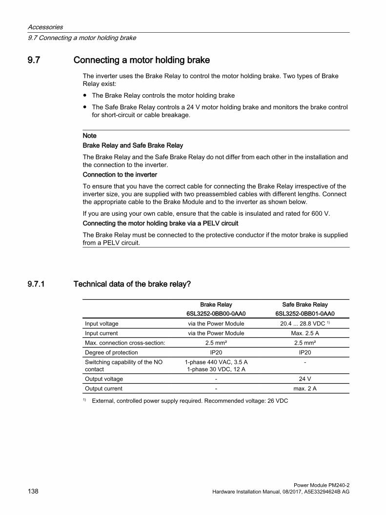
9.7 Connecting a motor holding brakeThe inverter uses the Brake Relay to control the motor holding brake. Two types of Brake Relay exist:
● The Brake Relay controls the motor holding brake
● The Safe Brake Relay controls a 24 V motor holding brake and monitors the brake control for short-circuit or cable breakage.
NoteBrake Relay and Safe Brake Relay
The Brake Relay and the Safe Brake Relay do not differ from each other in the installation and the connection to the inverter.Connection to the inverter
To ensure that you have the correct cable for connecting the Brake Relay irrespective of the inverter size, you are supplied with two preassembled cables with different lengths. Connect the appropriate cable to the Brake Module and to the inverter as shown below.
If you are using your own cable, ensure that the cable is insulated and rated for 600 V.Connecting the motor holding brake via a PELV circuit
The Brake Relay must be connected to the protective conductor if the motor brake is supplied from a PELV circuit.
9.7.1 Technical data of the brake relay?
Brake Relay6SL3252-0BB00-0AA0
Safe Brake Relay6SL3252-0BB01-0AA0
Input voltage via the Power Module 20.4 ... 28.8 VDC 1)
Input current via the Power Module Max. 2.5 AMax. connection cross-section: 2.5 mm² 2.5 mm²Degree of protection IP20 IP20Switching capability of the NO contact
1-phase 440 VAC, 3.5 A1-phase 30 VDC, 12 A
-
Output voltage - 24 VOutput current - max. 2 A
1) External, controlled power supply required. Recommended voltage: 26 VDC
Accessories9.7 Connecting a motor holding brake
Power Module PM240-2138 Hardware Installation Manual, 08/2017, A5E33294624B AG
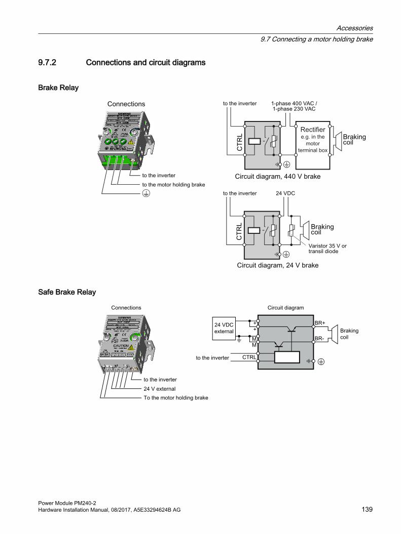
9.7.2 Connections and circuit diagrams
Brake Relay
Rectifier e.g. in the
motor
terminal box
Safe Brake Relay
Accessories9.7 Connecting a motor holding brake
Power Module PM240-2Hardware Installation Manual, 08/2017, A5E33294624B AG 139

9.7.3 Mounting and connecting the brake relay
Installing the Brake Relay● FSA … FSC: Install the Brake Relay next to the Power Module.
● FSD … FSF: Install the Brake Relay at the rear of the lower shield plate. Attach the Brake Relay before you install the shield plate.
AUTOHOTSPOT
Connecting the Brake Relay to the inverterThe connector for the Brake Relay is located at the front of the Power Module. Lay the cable harness for the Brake Relay in the cable routing.
Accessories9.7 Connecting a motor holding brake
Power Module PM240-2140 Hardware Installation Manual, 08/2017, A5E33294624B AG
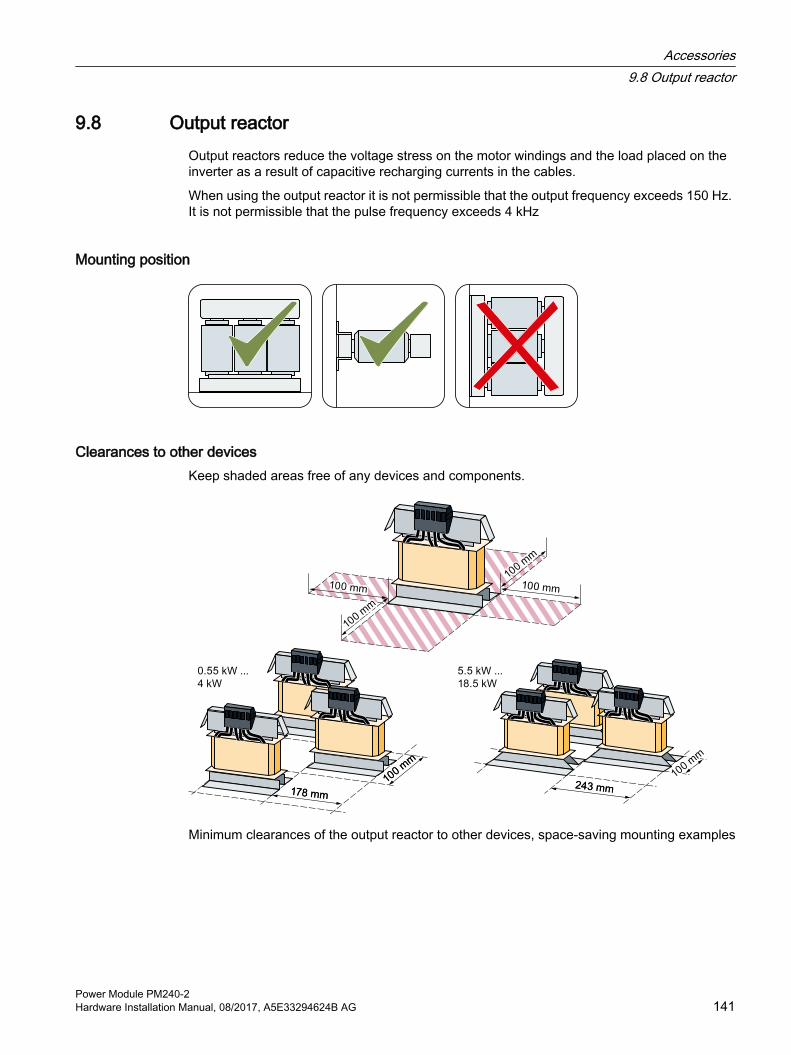
9.8 Output reactorOutput reactors reduce the voltage stress on the motor windings and the load placed on the inverter as a result of capacitive recharging currents in the cables.
When using the output reactor it is not permissible that the output frequency exceeds 150 Hz. It is not permissible that the pulse frequency exceeds 4 kHz
Mounting position
Clearances to other devicesKeep shaded areas free of any devices and components.
Minimum clearances of the output reactor to other devices, space-saving mounting examples
Accessories9.8 Output reactor
Power Module PM240-2Hardware Installation Manual, 08/2017, A5E33294624B AG 141
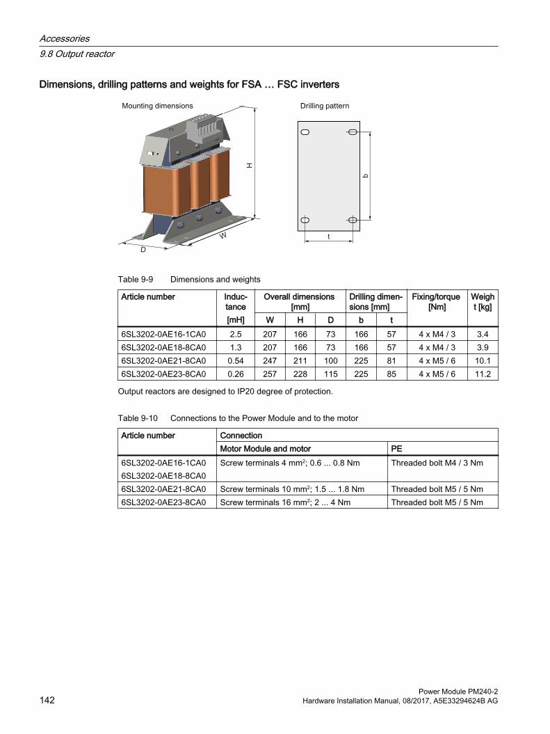
Dimensions, drilling patterns and weights for FSA … FSC inverters
Table 9-9 Dimensions and weights
Article number Induc‐tance[mH]
Overall dimensions [mm]
Drilling dimen‐sions [mm]
Fixing/torque [Nm]
Weight [kg]
W H D b t6SL3202-0AE16-1CA0 2.5 207 166 73 166 57 4 x M4 / 3 3.46SL3202-0AE18-8CA0 1.3 207 166 73 166 57 4 x M4 / 3 3.96SL3202-0AE21-8CA0 0.54 247 211 100 225 81 4 x M5 / 6 10.16SL3202-0AE23-8CA0 0.26 257 228 115 225 85 4 x M5 / 6 11.2
Output reactors are designed to IP20 degree of protection.
Table 9-10 Connections to the Power Module and to the motor
Article number ConnectionMotor Module and motor PE
6SL3202-0AE16-1CA06SL3202-0AE18-8CA0
Screw terminals 4 mm2; 0.6 ... 0.8 Nm Threaded bolt M4 / 3 Nm
6SL3202-0AE21-8CA0 Screw terminals 10 mm2; 1.5 ... 1.8 Nm Threaded bolt M5 / 5 Nm6SL3202-0AE23-8CA0 Screw terminals 16 mm2; 2 ... 4 Nm Threaded bolt M5 / 5 Nm
Accessories9.8 Output reactor
Power Module PM240-2142 Hardware Installation Manual, 08/2017, A5E33294624B AG

Dimensions, drilling patterns and weights for FSD … FSF inverters
Figure 9-7 Dimensions and drilling patterns
Table 9-11 Dimensions and weights
Article number Overall dimensions [mm]
Drilling dimensions [mm]
Fixing/torque [Nm]
Weight [kg]
W H D b t1 t26SE6400-3TC07-5ED0 270 248 209 200 102 91.5 4 x M8 / 13 26.56SE6400-3TC14-5FD0 350 321 288 264 140 134 4 x M8 / 13 576SL3000-2BE32-1AA0 300 285 257 224 165 78 4 x M8 / 13 606SL3000-2BE32-6AA0 300 315 277 224 185 78 4 x M8 / 13 666SL3000-2AH31-0AA0 270 248 200 200 103 82 4 x M8 / 13 256SL3000-2AH31-5AA0 270 248 200 200 103 82 4 x M8 / 13 26
Output reactors are designed to IP20 degree of protection.
Table 9-12 Connections to the Power Module and to the motor
Article number ConnectionMotor Module and motor PE
6SE6400-3TC07-5ED0 Cable lug M6 / 6 Nm Screw M6 / 10 Nm6SE6400-3TC14-5FD0 Cable lug M8 / 13 Nm Screw M8 / 25 Nm6SL3000-2BE32-1AA06SL3000-2BE32-6AA0
Cable lug M10 / 50 Nm Screw M8 / 25 Nm
6SL3000-2AH31-0AA06SL3000-2AH31-5AA0
Cable lug M10 / 50 Nm Screw M6 / 10 Nm
Accessories9.8 Output reactor
Power Module PM240-2Hardware Installation Manual, 08/2017, A5E33294624B AG 143

Table 9-13 Assignment table for 200 V Power Modules
Power Module Output reactor Frame size Article number Power [kW] Article numberFSAFSAFSB
6SL3210-1PB13-0 . L06SL321 . -1PB13-8 . L06SL3210-1PB15-5 . L0
0.550.751.1
6SL3202-0AE16-1CA0
FSB 6SL3210-1PB17-4 . L0 1.5 6SL3202-0AE18-8CA0FSBFSCFSC
6SL321 . -1PB21-0 . L06SL3210-1PB21-4 . L06SL321 . -1PB21-8 . L0
2.234
6SL3202-0AE21-8CA0
FSCFSC
6SL321 . -1PC22-2 . L06SL3210-1PC22-8 . L0
5.57.5
6SL3202-0AE23-8CA0
FSDFSDFSD
6SL3210-1PC24-2UL06SL3210-1PC25-4UL06SL321 . -1PC26-8UL0
1115
18.5
6SE6400-3TC07-5ED0
FSEFSEFSFFSFFSF
6SL3210-1PC28-0UL06SL321 . -1PC31-1UL06SL3210-1PC31-3UL06SL3210-1PC31-6UL06SL321 . -1PC31-8UL0
2230374555
6SE6400-3TC14-5FD0
Output reactors are not required for inverters of frame sizes FSD … FSF
Table 9-14 Assignment table for 400 V Power Modules
Power Module Output reactor Frame size Article number Power [kW] Article numberFSAFSAFSAFSAFSA
6SL3210-1PE11-8 . L16SL3210-1PE12-3 . L16SL3210-1PE13-2 . L16SL3210-1PE14-3 . L16SL3210-1PE16-1 . L1
0.550.751.11.52.2
6SL3202-0AE16-1CA0
FSA 6SL321 . -1PE18-0 . L1 3 6SL3202-0AE18-8CA0FSBFSBFSB
6SL3210-1PE21-1 . L06SL3210-1PE21-4 . L06SL321 . -1PE21-8 . L0
45.57.5
6SL3202-0AE21-8CA0
FSCFSC
6SL3210-1PE22-7 . L06SL321 . -1PE23-3 . L0
1115
6SL3202-0AE23-8CA0
FSDFSDFSDFSD
6SL3210-1PE23-8 . L06SL3210-1PE24-5 . L06SL3210-1PE26-0 . L06SL321 . -1PE27-5 . L0
18.5223037
6SE6400-3TC07-5ED0
FSEFSEFSFFSF
6SL3210-1PE28-8 . L06SL321 . -1PE31-1 . L06SL3210-1PE31-5 . L06SL3210-1PE31-8 . L0
45557590
6SE6400-3TC14-5FD0
FSF 6SL3210-1PE32-1 . L0 110 6SL3000-2BE32-1AA0FSF 6SL321 . -1PE32-5 . L0 132 6SL3000-2BE32-6AA0
Output reactors are not required for inverters of frame sizes FSD … FSF
Accessories9.8 Output reactor
Power Module PM240-2144 Hardware Installation Manual, 08/2017, A5E33294624B AG

Table 9-15 Assignment table for 690 V Power Modules
Power Module Output reactor Frame size Article number Power [kW] Article numberFSF 6SL3210-1PH28-0 . L0
6SL3210-1PH31-0 . L07590
6SL3000-2AH31-0AA0
FSF 6SL3210-1PH31-2 . L06SL321 . -1PH31-4 . L0
110132
6SL3000-2AH31-5AA0
Output reactors are not required for 690 V inverters
Accessories9.8 Output reactor
Power Module PM240-2Hardware Installation Manual, 08/2017, A5E33294624B AG 145

9.9 Voltage limiter and du/dt filterA combination of du/dt filter and a voltage peak limiter (VPL) are available to suppress voltage peaks.
Further details for the functional principle and the application cases are available at:Voltage limiter and du/dt filter (https://support.industry.siemens.com/cs/ww/de/view/109742112)
The assignment of the du/dt filter / VPL combination to the Power Modules is contained in the following tables.
Assignment tables
Table 9-16 Assignment table for 200 V Power Modules
Power Module VPL-du/dt Frame size Article number Power [kW] Article numberFSDFSDFSDFSEFSEFSFFSFFSF
6SL3210-1PC24-2UL06SL3210-1PC25-4UL06SL321 . -1PC26-8UL06SL3210-1PC28-0UL06SL321 . -1PC31-1UL06SL3210-1PC31-3UL06SL3210-1PC31-6UL06SL321 . -1PC31-8UL0
1115
18.52230374555
6SL3000-2DE32-6AA0
Table 9-17 Assignment table for 400 V Power Modules
Power Module VPL-du/dt Frame size Article number Power [kW] Article numberFSFFSFFSFFSF
6SL3210-1PE31-5 . L06SL3210-1PE31-8 . L06SL3210-1PE32-1 . L06SL321 . -1PE32-5 . L0
7590
110132
6SL3000-2DE32-6AA0
Accessories9.9 Voltage limiter and du/dt filter
Power Module PM240-2146 Hardware Installation Manual, 08/2017, A5E33294624B AG

Table 9-18 Assignment table for 690 V Power Modules
Power Module VPL-du/dt Frame size Article number Power [kW] Article numberFSDFSDFSDFSDFSDFSDFSEFSEFSFFSF
6SL3210-1PH21-4 . L06SL3210-1PH22-0 . L06SL3210-1PH22-3 . L06SL3210-1PH22-7 . L0 6SL3210-1PH23-5 . L0 6SL321 . -1PH24-2 . L06SL3210-1PH25-2 . L0 6SL321 . -1PH26-2 . L06SL3210-1PH28-0 . L0 6SL3210-1PH31-0 . L0
11 15
18.522 30 37 4555 7590
6SL3000-2DH31-0AA0
FSFFSF
6SL3210-1PH31-2 . L06SL321 . -1PH31-4 . L0
110132
6SL3000-2DH31-5AA0
Accessories9.9 Voltage limiter and du/dt filter
Power Module PM240-2Hardware Installation Manual, 08/2017, A5E33294624B AG 147

Accessories9.9 Voltage limiter and du/dt filter
Power Module PM240-2148 Hardware Installation Manual, 08/2017, A5E33294624B AG

Appendix AA.1 Manuals and technical support
A.1.1 Manuals for your inverter
Manuals with additional information that can be downloaded:● Power Module Installation Manual (https://support.industry.siemens.com/cs/ww/en/ps/
13224/man)Installing Power Modules, reactors and filters. Technical specifications, maintenance (this manual)
● CU230P-2 Compact Operating Instructions (https://support.industry.siemens.com/cs/ww/en/view/109477360)Commissioning the inverter
● CU240B/E-2 Compact Operating Instructions (https://support.industry.siemens.com/cs/ww/en/view/109477361)Commissioning the inverter
● CU250S-2 Compact Operating Instructions (https://support.industry.siemens.com/cs/ww/en/view/99730303)Commissioning the inverter.
● CU230P-2 operating instructions (https://support.industry.siemens.com/cs/ww/en/view/109478827)Installing, commissioning and maintaining the inverter. Advanced commissioning
● CU240B/E-2 operating instructions (https://support.industry.siemens.com/cs/ww/en/view/109478828)Installing, commissioning and maintaining the inverter. Advanced commissioning
● CU250S-2 operating instructions (https://support.industry.siemens.com/cs/ww/en/view/109478829)Installing, commissioning and maintaining the inverter. Advanced commissioning
● "Safety Integrated" function manual (https://support.industry.siemens.com/cs/ww/en/view/109483003)Configuring PROFIsafe. Installing, commissioning and operating fail-safe functions of the frequency converter.
Power Module PM240-2Hardware Installation Manual, 08/2017, A5E33294624B AG 149

● CU230P-2 List Manual (https://support.industry.siemens.com/cs/ww/en/view/109477248)Parameter list, alarms and faults. Graphic function diagrams
● CU240B/E-2 List Manual (https://support.industry.siemens.com/cs/ww/en/view/109477251)Parameter list, alarms and faults. Graphic function diagrams
● CU250S-2 List Manual (https://support.industry.siemens.com/cs/ww/en/view/109477253)Parameter list, alarms and faults. Graphic function diagrams
● EMC installation guideline (http://support.automation.siemens.com/WW/view/en/60612658)EMC-compliant control cabinet design, equipotential bonding and cable routing
● Accessories manual (https://support.industry.siemens.com/cs/ww/en/ps/13225/man)Installation descriptions for inverter components, e.g. line reactors and line filters. The printed installation descriptions are supplied together with the components.
A.1.2 Configuring support
CatalogOrdering data and technical information for SINAMICS G inverters.
Catalogs for download or online catalog (Industry Mall):
All about SINAMICS G120 (www.siemens.com/sinamics-g120)
SIZERThe configuration tool for SINAMICS, MICROMASTER and DYNAVERT T drives, motor starters, as well as SINUMERIK, SIMOTION controllers and SIMATIC technology
SIZER on DVD:
Article number: 6SL3070-0AA00-0AG0
Download SIZER (http://support.automation.siemens.com/WW/view/en/10804987/130000)
EMC (electromagnetic compatibility) technical overviewStandards and guidelines, EMC-compliant control cabinet design
AppendixA.1 Manuals and technical support
Power Module PM240-2150 Hardware Installation Manual, 08/2017, A5E33294624B AG

EMC overview (https://support.industry.siemens.com/cs/ww/en/view/103704610)
EMC Guidelines configuration manualEMC-compliant control cabinet design, potential equalization and cable routing
EMC installation guideline (http://support.automation.siemens.com/WW/view/en/60612658)
Safety Integrated for novices technical overviewApplication examples for SINAMICS G drives with Safety Integrated
Safety Integrated for novices (https://support.industry.siemens.com/cs/ww/en/view/80561520)
A.1.3 Product SupportYou can find additional information on the product and more in the Internet under (http://www.siemens.com/automation/service&support)
This address provides the following:
● Actual product information (product memorandums), FAQs (frequently asked questions), downloads.
● The Newsletter contains the latest information on the products you use.
● The Knowledge Manager (Intelligent Search) helps you find the documents you need.
● Users and specialists from around the world share their experience and knowledge in the Forum.
● You can find your local representative for Automation & Drives via our contact database under "Contact & Partner".
● Information about local service, repair, spare parts and much more can be found under "Services".
AppendixA.1 Manuals and technical support
Power Module PM240-2Hardware Installation Manual, 08/2017, A5E33294624B AG 151

A.2 DisposalProtecting the environment and preserving its resources are corporate goals of the highest priority for Siemens. Our worldwide environmental management system according to ISO 14001 ensures compliance with legislation and sets high standards in this regard. Environmentally friendly design, technical safety and health protection are always firm goals, even at the product development stage.
Recommendations for the environmentally friendly disposal of the machine and its components are given in the following chapter.
● Be sure to comply with local disposal regulations.
● Separate the housing parts according to their material.
● Dispose of the parts in accordance with the applicable legal regulations.
● Dispose of the packaging material in accordance with the applicable legal regulations.
Components● Sort the components for recycling according to whether they are:
– Electronic waste
– Scrap iron, e.g. shield plates
– Aluminum
– Insulating materials and plastics
AppendixA.2 Disposal
Power Module PM240-2152 Hardware Installation Manual, 08/2017, A5E33294624B AG
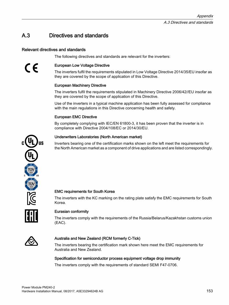
A.3 Directives and standards
Relevant directives and standardsThe following directives and standards are relevant for the inverters:
European Low Voltage DirectiveThe inverters fulfil the requirements stipulated in Low Voltage Directive 2014/35/EU insofar as they are covered by the scope of application of this Directive.
European Machinery DirectiveThe inverters fulfil the requirements stipulated in Machinery Directive 2006/42//EU insofar as they are covered by the scope of application of this Directive.
Use of the inverters in a typical machine application has been fully assessed for compliance with the main regulations in this Directive concerning health and safety.
European EMC DirectiveBy completely complying with IEC/EN 61800-3, it has been proven that the inverter is in compliance with Directive 2004/108/EC or 2014/30/EU.
Underwriters Laboratories (North American market)Inverters bearing one of the certification marks shown on the left meet the requirements for the North American market as a component of drive applications and are listed correspondingly.
EMC requirements for South KoreaThe inverters with the KC marking on the rating plate satisfy the EMC requirements for South Korea.
Eurasian conformityThe inverters comply with the requirements of the Russia/Belarus/Kazakhstan customs union (EAC).
Australia and New Zealand (RCM formerly C-Tick)The inverters bearing the certification mark shown here meet the EMC requirements for Australia and New Zealand.
Specification for semiconductor process equipment voltage drop immunityThe inverters comply with the requirements of standard SEMI F47-0706.
AppendixA.3 Directives and standards
Power Module PM240-2Hardware Installation Manual, 08/2017, A5E33294624B AG 153

Quality systemsSiemens AG employs a quality management system that meets the requirements of ISO 9001 and ISO 14001.
Certificates for download● EC Declaration of Conformity:
(https://support.industry.siemens.com/cs/ww/en/view/58275445)
● Certificates for the relevant directives, prototype test certificates, manufacturers declarations and test certificates for functions relating to functional safety ("Safety Integrated"): (http://support.automation.siemens.com/WW/view/en/22339653/134200)
● UL certificates: (http://database.ul.com/cgi-bin/XYV/template/LISEXT/1FRAME/index.html)
– FSA, FSB, FSC: 200 V UL File E121068, Vol. 2 Sec. 29
– FSA, FSB, FSC: 400 V UL File E121068, Vol. 2 Sec. 27
– FSD, FSE, FSF: 200 V / 400 V / 690 V UL File E192450, Vol. 13 Sec. 4
Standards that are not relevant
China Compulsory CertificationThe inverters do not fall in the area of validity of the China Compulsory Certification (CCC).
AppendixA.3 Directives and standards
Power Module PM240-2154 Hardware Installation Manual, 08/2017, A5E33294624B AG

A.4 Abbreviations
Abbreviation ExplanationAC Alternating currentCE Communauté EuropéenneCU Control UnitDC Direct currentDI Digital inputDIP switch DIP switches are small switches, found mostly on PBCs, for making basic
device settingsDO Digital outputECD Equivalent circuit diagramEEC European Economic Community ELCB Earth leakage circuit breakerEMC Electromagnetic compatibility (EMC)EMI Electromagnetic interferenceFS… Frame size ...HO High overload I/O Input/OutputIGBT Insulated gate bipolar transistorLED Light emitting diodeLO Low overload NC NC contactNEMA National Electrical Manufacturers AssociationNO NO contactOPI Operating instructionsPELV Protective extra low voltagePM Power ModulePPE Personnel protective equipmentPT Push-through technology RCCB Residual-current operated circuit breakerRCD Residual current deviceRFI Radio frequency interferenceSELV Safety extra-low voltageVPL Voltage Peak Limiter; component for limiting voltage peaks
AppendixA.4 Abbreviations
Power Module PM240-2Hardware Installation Manual, 08/2017, A5E33294624B AG 155

AppendixA.4 Abbreviations
Power Module PM240-2156 Hardware Installation Manual, 08/2017, A5E33294624B AG

Index
887 Hz characteristic, 66
AAir barrier, 32
BBase load, 77Base load input current, 77Base load output current, 77Base load power, 77Brake Relay, 138Braking resistor
Clearances, 131Dimension drawings, 132Installation, 131
CCatalog, 150Category C2, 59Category C3, 59Clearances, 131Commutation dips, 126Configuring support, 150Cooling, 32
DDegree of protection, 23Delta connection, 66Derating
Installation altitude, 109Dimension drawings, 127, 132, 141, 142, 143Disposal, 152Drilling pattern, 127, 132, 142, 143
EElectrical installation, 47EMC, 26
FField weakening, 66Function Manual, 149
GGetting Started, 149
HHardware Installation Manual, 149Harmonic currents, 115Harmonics, 115, 126High Overload, 77Hotline, 151
IIndustry Mall, 150Installation altitude, 109Installing, 33IT system, 50
LLine reactor
Dimension drawings, 127Line supply type, 50List Manual, 149Low Overload, 77
MMaintenance
Cleaning, 68Dirt, 68Pollution, 68Terminals, 68Ventilation, 68
NNeutral conductor, 50
Power Module PM240-2Hardware Installation Manual, 08/2017, A5E33294624B AG 157

OOperating instructions, 149Output reactor
Dimension drawings, 141, 142, 143Overvoltage protection, 126
PPower distribution systems, 50Protective conductor, 50
QQuestions, 151
SSafe Brake Relay, 138Safety notes
Electrical installation, 47Service life of the fan, 70SIZER, 150Standards
EN 61800-3, 153Star connection (Y), 66Support, 151
TTN system, 50TT system, 50
Index
Power Module PM240-2158 Hardware Installation Manual, 08/2017, A5E33294624B AG


For further
information about
SINAMICS G120,
scan the QR code.
Germany
Further information
Industry Mall:
Industry Online Support (Service and Support):
SINAMICS inverters:www.siemens.com/sinamics
www.siemens.com/online-support
www.siemens.com/industrymall
Siemens AG
Digital Factory
Motion Control
Postfach 3180
91050 ERLANGEN