hard disk drive components hdd. components basic components of a hard drive disk platters read/write...
TRANSCRIPT

Hard Disk Drive Components
HDD
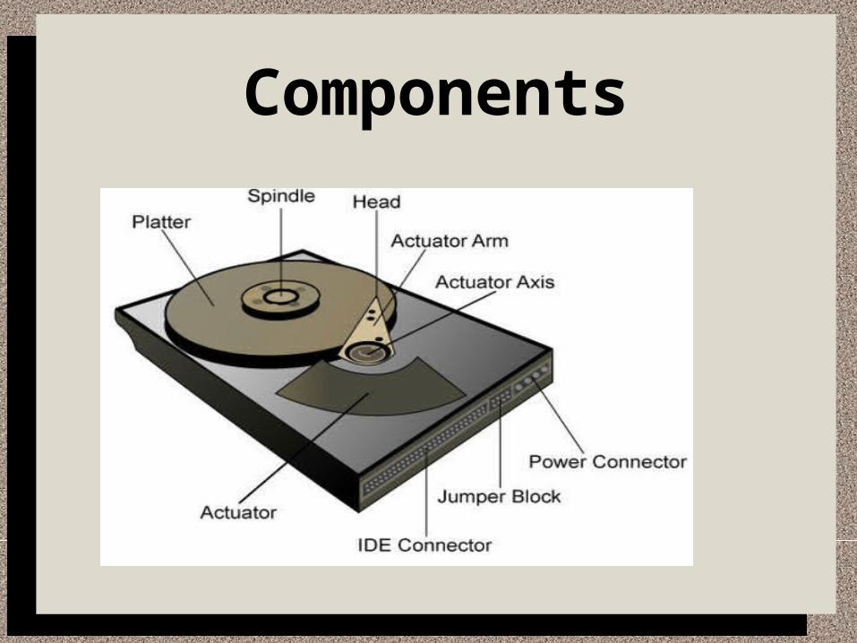
Components

Basic components of a hard drive
• Disk platters• Read/write heads• Head actuator mechanisms• Spindle motor• Logic board• Cables & connectors• Configuration items (such as jumpers &
switches)

Hard Disk Platters
• Hard disks have been a number of different form factors over the years
• 3 1/2 inch drives are the most popular for desktop & some portables
• Max number of platters in a 3 1/2 inch drive is 11
• Traditionally made from aluminum alloy
• Desire for higher density has led to the use of platters made of glass (glass
ceramic composite)
– Glass platters offer greater rigidity & more stable thermally
• Traditionally made from aluminum alloy
• Desire for higher density has led to the use of platters made of glass (glass
ceramic composite)
– Glass platters offer greater rigidity & more stable thermally

Hard Disk Platters
• No matter what type of platter is used, the platters are covered with a thin
layer of magnetically retentive substance (called the medium) on which
magnetic information is stored.
– Oxide media
– Thin-film media

Oxide media
• Made of various compounds, oxide being the primary active ingredient
• Put on the disk like syrup, coating the entire disk
• Coating is approx 30 millionths of an inch and is made smooth
• Platters appear to look brownish or amber
• Very sensitive to head-crash during movement of operation
• Very few drives use this technology anymore

Thin-film media
• Thinner, harder & more perfectly formed than oxide media
• High-performance medium that enabled a new generation of drives to have
lower head floating heights, which in turn made increase in drive density
possible
• Coating is put on the platter using an electroplating mechanism, similar to
that of putting chrome plating on the bumper of the car.
• Looks silver like the surface of a mirror

Read/Write Heads
• A hard disk has one read/write head for each side of the platter
• The heads are connected on a single movement mechanism
• They move in unison
• Each head is on an actuator arm that is spring-loaded to force the head into contact
with a platter
– The heads float only a very slight distance above the platter
• When the drive is at rest, the heads are forced into direct contact with the platters by
spring tension
• Four types of read/write head designs:
– Ferrite
– Metal-In-Cap
– Thin-film
– Magneto-resistive

Ferrite• Virtually obsolete
• Had an iron-oxide core wrapped by passing a magnetic field near them
• Heads were large & heavy
• Required a much higher floating height than today

Metal-In-Gap
• Enhanced version of the ferrite heads
• Virtually obsolete
• Have a layer of magnetic alloy, which increased the magnetization
capability & allowed the heads tow rite at higher densities
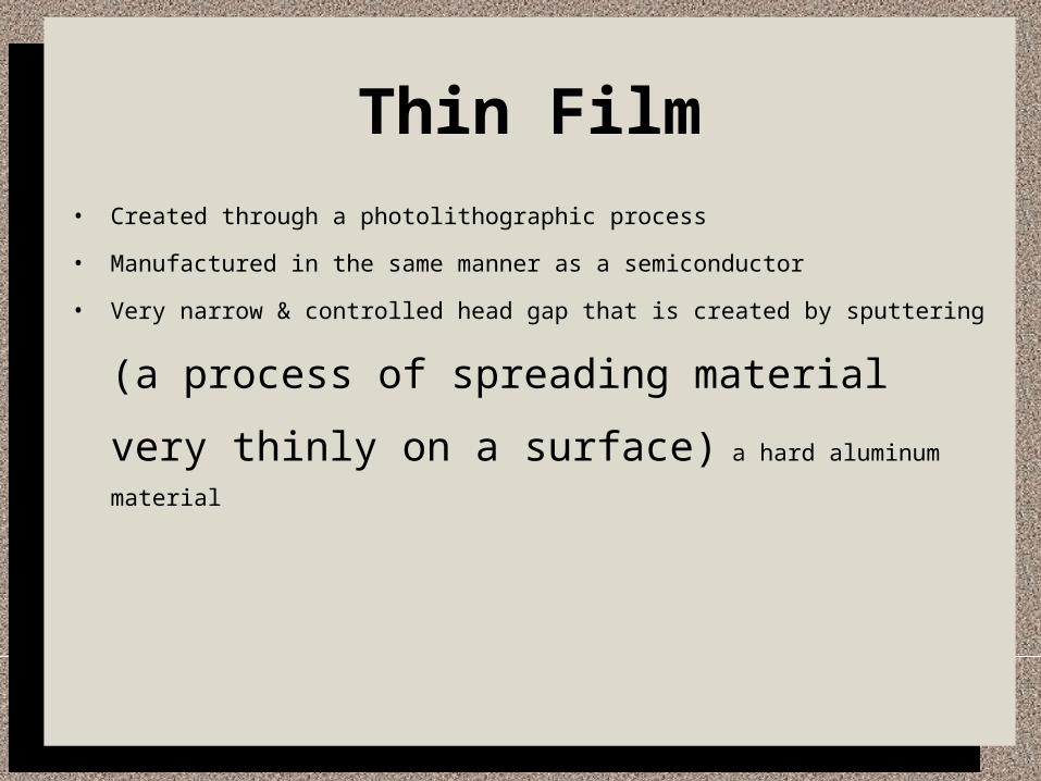
Thin Film
• Created through a photolithographic process
• Manufactured in the same manner as a semiconductor
• Very narrow & controlled head gap that is created by sputtering (a process of
spreading material very thinly on a surface) a hard aluminum
material
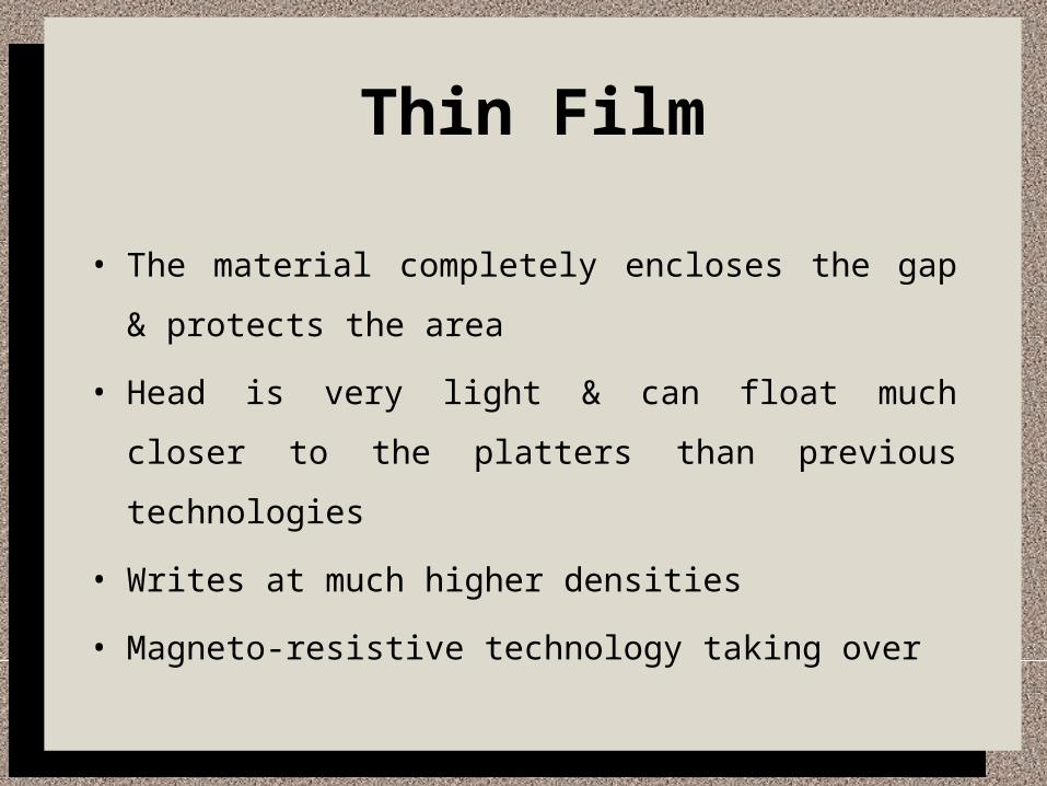
Thin Film
• The material completely encloses the gap & protects the
area
• Head is very light & can float much closer to the platters
than previous technologies
• Writes at much higher densities
• Magneto-resistive technology taking over

Magneto-Resistive• Latest in technology & highest performance available
• As areal density increases (technology growth rate indicator), TF and MIG will disappear
• Relies on the fact that the resistance of a conductor changes slightly when an external magnetic field
is present
• Two heads in one - MR heads do not write
• They are sensors for reading
• The heads have two separate elements
– TF for writing
– MR for reading
• Each head optimized for its task

Head Actuator Mechanism
• A drive using a stepper motor is much less reliable than one using a voice coil
• Floppy drives use a stepper motor to position their heads
• Accuracy of the stepper is suited to a floppy drive, because track densities
usually lower
• Moves the heads across the disk & positions them accurately above the
desired cylinder
• Two basic categories
– Stepper Motor actuators
– Voice coil actuators
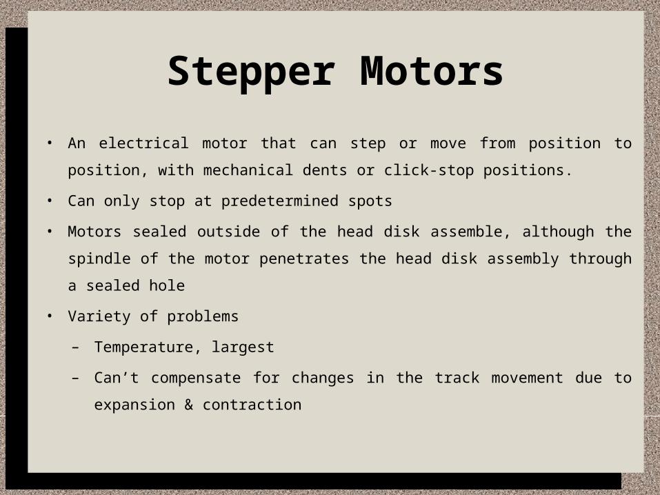
Stepper Motors
• An electrical motor that can step or move from position to position, with mechanical
dents or click-stop positions.
• Can only stop at predetermined spots
• Motors sealed outside of the head disk assemble, although the spindle of the motor
penetrates the head disk assembly through a sealed hole
• Variety of problems
– Temperature, largest
– Can’t compensate for changes in the track movement due to expansion &
contraction
Voice Coil• Used in almost all hard drives today
• Uses feedback signal from drive to accurately determine head positions &
adjust them
• Works by pure electromagnetic force
• Similar to construction of a typical audio speaker
• Audio speaker uses a stationary magnet surrounded by a voice coil which is
connected to the speakers paper cone
• When the coil is energized, it moves & produces sound from the cone
• In a typical hard disk, the electromagnetic coil is attached to the end of the
head rack & placed near a stationary magnet

Voice Coil
• There is no physical contact between the coil & the magnet
• It moves by electromagnetic force
• This force moves the head rack.
• Use a servo-mechanism to move to the desired position on the disk
– Stepper motors move to predetermined spots
• Not affected by temperature
• Automatic head parking
– Heads are positioned by magnetic force, so when power removed,
mag field disappears & heads stop

Air filters
• Most have two
– Recirculating filter - filters small particles scraped off the platers during
takeoffs & landings
– Breather filter - allows for pressure equalization
• Heads don’t float if pressure not right
• Drives are sensitive to temperature
• If the drive has been very cold, let it warm up before powering on
• Watch humidity
Spindle motor
• Motor that spins the platters
• Connected directly to the drive

Logic Boards
• Mounted on the hard drive
• Contain electronics that control the drive’s spindle &
head actuator systems & present the data to the
controller

Cables & Connectors
• Sever connectors for interfacing to the computer,
receiving power & sometimes grounding to the system
chassis
• Three types
– Interface connectors
– Power connectors
– Option ground connector (green wire)
Power Connector
• Usually same 4-pin connector type that is used in a floppy disk
drive
• Same power-supply connector plugs into it
• Most use both 5 & 12 volt power
– Red, yellow, 2 black with keyed white end

THANK YOU