handbook understanding isolation
TRANSCRIPT

Understanding IsolationHANDBOOK
broadcom.com

2
Broadcom — Industry Leader in High Performance Optocouplers
Gate Drive Optocouplers
Very high CMR performance (signal isolation)
More integrated features to protect IGBT, eg. Miller Clamp, etc.
Smaller packages- space/cost saving on board
Up to 20% cost saving on certain products
Current & Voltage Sensing Optocouplers
High Accuracy
Low Drift over Temperature
Smaller footprint-space/cost saving on board
Up to 40% cost saving vs. Hall effect sensor
Low Power Digital Optocouplers
Low power consumption (more than 80% power saving)
Extreme common-mode noise rejection
Up to 20% cost saving on certain products
Applications
Industrial Drives, Industrial Networking, Motor Control, PLC Input/Output Isolation, Power Distribution Systems, Robotics, Switching Power Supplies

3
Broadcom Optocouplers — Industry Leader in Isolation Performance
Value Proposition of Opto-Isolation:• True Galvanic Isolation
• Reinforced = failsafe Isolation
• Excellent Signal Immunity
• Low impedance LED input (Ohm) = rejection of conducted & inducted EMI
• Very low inherent capacitance (pF) = no Common Mode Noise failure through leakage currents caused by Transients
• No Inductance
• Very Low Power Consumption (mWatt)
• Fast reaction times & endurance
• High performance LED technology (30 years field life)
Safe Isolation
Safety Approval UL, CSA and IEC/EN/DIN EN
60747-5-5
Other Suppliers of Isolation Technologies
in the market (list not complete)
Opto-Isolation: Broadcom, Fairchild,
Toshiba, Vishay, Renesas, Sharp
Alternative isolation technology:
TI, ADI, SiLabs, Infineon
4
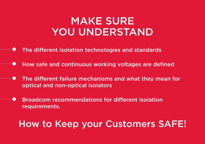
MAKE SURE YOU UNDERSTAND
The different isolation technologies and standards
How safe and continuous working voltages are defined
The different failure mechanisms and what they mean for optical and non-optical isolators
Broadcom recommendations for different isolation requirements.
How to Keep your Customers SAFE!
5
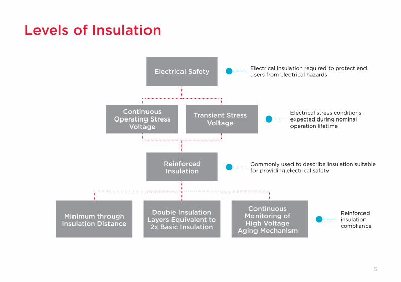
Levels of Insulation
Electrical insulation required to protect end users from electrical hazards
Electrical stress conditions expected during nominal operation lifetime
Commonly used to describe insulation suitable for providing electrical safety
Reinforced insulation compliance
Electrical Safety
Minimum through Insulation Distance
Double Insulation Layers Equivalent to 2x Basic Insulation
Continuous Monitoring of High Voltage
Aging Mechanism
Continuous Operating Stress
Voltage
Transient Stress Voltage
Reinforced Insulation

6
What is the Difference Between Isolation and Insulation?
Broadcom OptocouplersDTI: 80 µm to 1000 µm
Number of Layers: 3Insulation Material: Polyimide Tape + Silicone
Electric Field Stress: Vbias / 80 µm
Typical Magnetic or Capacitive IsolatorsDTI: 8 µm to 17 µmNumber of Layers: 1
Insulation Material: SiO2 or PolyimideElectric Field Stress: Vbias / 8 µm
Although both terms are often used interchangeably, isolation refers to the separation between two systems or voltage levels, while insulation refers to the actual medium being used to do the separation. For example, an optocoupler is an isolation device with a silicon insulation barrier between the LED emitter and diode detector.
Silicone
Silicone
Insulation Tape
Top Passivation: BCB
Bottom Metal Layer
Insulation Layer
Top Metal Layer
DTI

7
Safety Standards for Optocouplers and Isolators
Make Sure You Understand!!!Talk to the right people at your customer. Standards and Quality departments are responsible for safety!
IEC60664 — Insulation Coordinates for Low Voltage Equipment3.3.2.2 Long term stresses and their effects3.3.2.2.1 Partial discharges3.3.2.3 Other stresses. Many other stresses can damage insulation and will have to be taken into account by technical committees
VDE0884 – Optocoupler Safety StandardUse Partial discharge testing to provide 100% screen of HV lifetime
Draft Standard VDE0884-10 Edition 1 Magnetic Isolator StandardUses only partial discharge testing to provide check of HV lifetime. Principle HV aging mechanism not checked
Draft Standard VDE0884-10 Edition 2 Uses partial discharge testing and type testing of principle aging mechanism to provide prediction of HV lifetime. Basic Insulation rating added.
IEC Version of Draft VDE0884-11Committee formed
Formalized EN Version of IEC Standard After voting and acceptance of IEC standard
IEC60747-5-5 and IEC60747-5-2 — Optocoupler Component Safety Standard
EN60747-5-5 Optocoupler Component Safety Standard

8
Defining a Safe Continuous Working Voltage
• Determine the safe continuous voltage level that does not damage the isolator ... You can clearly see the edge of the cliff
• The safe continuous working voltage level should be far enough away from the transient variations in the nominal working voltage ... If you take a step left or right, you still won’t fall off
• The safe continuous voltage level should not change over time ... The edge is stable and not moving.
Safe Continuous Working Voltage is … ... like walking along a cliff on a sunny day

9
Relevant Aging Mechanisms for Isolators
• Optocouplers — Use of thick insulation materials protects against space charge aging. Dominant failure mechanism is partial discharge.
• Magnetic isolators using spin on polyimide coatings — Use of thin polymer spin coatings <25 µm, results in high dielectric stress which readily activates space charge degradation. Dominant failure mechanism is space charge aging.
• Capacitive/Magnetic isolators using thin film SIO2<10µm. High E field stress readily activates SIO2 specific time depended failure mechanism. Dominant failure mechanism is SIO2 specific TDDB (time dependent dielectric breakdown).
Make Sure You Understand!!!
Different isolation technologies have
different failure mechanisms.

10
Working Voltage as Defined by IEC 60747-5-5
This is the maximum continuous voltage that the insulation barrier must survive over the lifetime of the device. The integrity of the insulation is guaranteed by a partial discharge test done on every production device.In applications where there are significant potential differences, the most important safety parameter is the maximum working insulation voltage (Viorm) as defined by IEC/EN/DIN EN 60747-5-5. This standard uses partial discharge testing to determine the working voltage level that the optical insulation must survive over the lifetime of the device. The philosophy underlying the partial discharge testing is that insulation for safe electrical isolation needs to withstand not only a breakdown voltage, but also a voltage that prevents any degradation due to high electrical fields which may cause the insulation to break down over time or over repetitive cycles. In production, partial discharge test is performed for 1 second at 1.875x Viorm.
Make Sure You Understand!!!Alternative isolating technologies are no longer IEC certified 60747-5-2.
They are certified according to the latest VDE safety draft standard – VDE0844-10.
PASS FAIL

11
Testing Relevant Aging Mechanisms for Non-optical Isolators
In magnetic isolators using spin on polyimide coatings, there is a higher dielectric stress which activates space charge degradation. The dominant failure mechanism is space charge aging, which reduces the breakdown voltage over time. Currently it is not possible to test for space charge degradation in a finished product.
In capacitive or magnetic isolators using thin film SIO2, the dominant failure mechanism is specific to the SIO2 technology and is called time dependent dielectric breakdown (TDDB). The test method to determine TDDB is destructive and cannot be tested in production.
PASS FAIL

12
Why Can’t Partial Discharge Testing be Used on Non-optical Isolators?
Theoretically it can be done, however practically it is not valid as the dominant failure mechanism in these alternative technologies is different and cannot be detected by a partial discharge test. Alternative isolators, which passed partial discharge testing failed just hours later when subjected to a continuous voltage used in the partial discharge test (which optocouplers passed).
High Voltage High Temperature TestTest Condition: Stress Voltage = 1.6kV, Temp: 125˚C
Test still on-going
Tim
e B
efo
re F
ailu
re (
HR
)
100
ACML-7410
Rated Viso 5kV 3.75kV 2.5kV 2.5kV 2.5kV5kV
ACPL-38JT Competitor APolymide
Competitor APolymide
Competitor BSI02
Competitor CSI02
800
700
600
500
400
300
200
0
24 Units@ 2283hrs
10 Units@ 2283hrs
3/5 Units fail @ 13hrs
3/5 Units fail @ 25hrs
2/5 Units fail @ 261hrs
5/5 Units fail @ 0.5hrs

13
Using VDE0884-11 to Certify Working Voltage
• Uses type testing and statistical modeling to predict HV lifetime. No continuous monitoring of dominant HV aging mechanism IEC60747-5-5 provides 100% continuous monitoring of dominant HV aging mechanism for optocouplers
• Permits/Predicts failures to occur during lifetime — 1000ppm for Basic insulation and 1ppm for reinforced insulation IEC60747-5-5 eliminates active HV aging mechanism in optocouplers — ensuring no failures over lifetime
• Safety factor for reinforced insulation of just 1.25. IEC insulation coordinates system nominal requires a safety factor of 2. IEC60747-5-5 uses a safety factor of 1.85
Make Sure You Understand!!!
The VDE0884-11 for reinforced isolation allows for 1 ppm for alternate isolators.
There is no continuous production monitoring in the VDE standard.
Make sure you understand the failure mechanisms in the different standards,
as test results can be misleading and dangerous.

14
Withstand Voltage as Defined by UL1577
This is the maximum voltage the insulation barrier needs to hold up to for a duration of one minute.The withstand voltage is a safety parameter defined by the dielectric voltage-withstand test according to UL1577. This is a one minute type test, where a voltage is applied between the input and output terminals of the isolator (destructive test). Typical withstand voltage ratings are 2500-5000 Vrms. This is the maximum voltage the insulation barrier needs to hold up to for one minute and is not related to high voltage over product lifetime. During manufacturing, each isolator is tested at 1.2x the rated dielectric insulation voltage for one second. UL1577 can be used to certify optocouplers as well as non-optical isolator technologies.
Make Sure You Understand!!!Withstand voltage is not the same as working voltage.
It defines the isolation voltage for a short term
overvoltage condition, not over lifetime.

15
Safe Isolation with Robust LED Technology
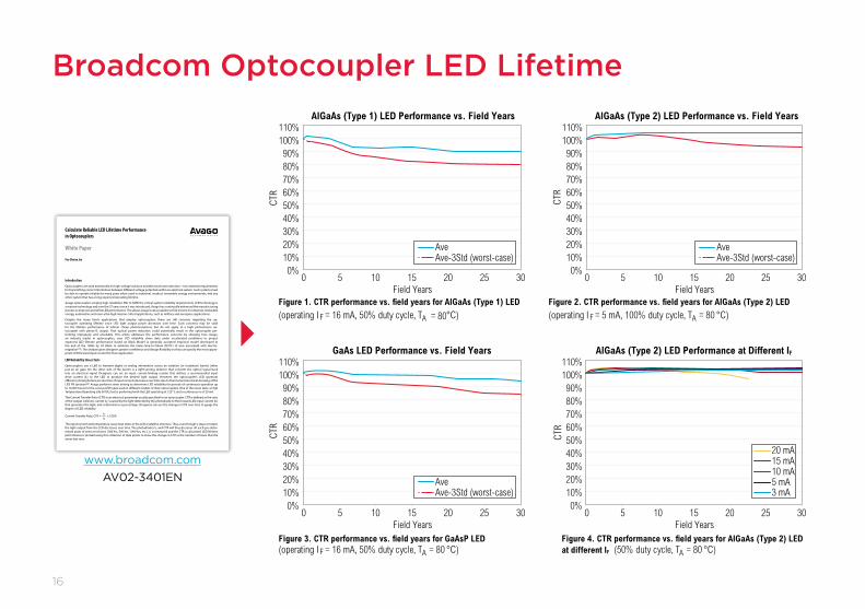
The lifetime of the LED will inherently depend on its quality grade. The LED used in low cost consumer grade phototransistor optocouplers could potentially degrade faster than an LED used in industrial or automotive grade photo-IC optocouplers. Broadcom has done extensive testing and provides LED lifetime performance data for all of its industrial and automotive grade optocouplers. Worst case predictions show a degradation of less than 10% for over 30 years of lifetime in the field.
Power• Low VF Material
• Low IF Drive
• Current-spreading Design
Efficiency• High-brightness
• Material LED Light Extraction
• Lens/Optics Design
Defects• Epitaxial Growth
• LED Fabrication
• Assembling
• Handling
Make Sure You Understand!!!
Light output degradation depends
on the quality of the LED being used. Comparative tests
are often done using low performance phototransistors.
Broadcom photo IC optocouplers use high performance, industrial
grade LEDs.
16
Broadcom Optocoupler LED Lifetime
0%10%20%30%40%50%60%70%80%90%
100%110%
CTR
Field Years0 5 10 15 20 25 30
0%10%20%30%40%50%60%70%80%90%
100%110%
CTR
Field Years
GaAs LED Performance vs. Field Years AlGaAs (Type 2) LED Performance at Different IF
0 5 10 15 20 25 30
20 mA15 mA10 mA5 mA3 mA
AveAve-3Std (worst-case)
0%10%20%30%40%50%60%70%80%90%
100%110%
CTR
Field Years
AlGaAs (Type 1) LED Performance vs. Field Years
0 5 10 15 20 25 300%
10%20%30%40%50%60%70%80%90%
100%110%
CTR
Field Years
AlGaAs (Type 2) LED Performance vs. Field Years
0 5 10 15 20 25 30
AveAve-3Std (worst-case)
AveAve-3Std (worst-case)
(operating I F = 16 mA, 50% duty cycle, TA = 80 °C)
(50% duty cycle, TA = 80 °C)
(operating I F = 16 mA, 50% duty cycle, TA = 80 °C)
(operating I F = 5 mA, 100% duty cycle, TA = 80 °C)
Figure 1. CTR performance vs. field years for AIGaAs (Type 1) LED
Figure 3. CTR performance vs. field years for GaAsP LED Figure 4. CTR performance vs. field years for AIGaAs (Type 2) LEDat different IF
Figure 2. CTR performance vs. field years for AIGaAs (Type 2) LED
www.broadcom.com AV02-3401EN
Calculate Reliable LED Lifetime Performance in Optocouplers
White Paper
Foo Chwan Jye
IntroductionOptocouplers are used extensively for high-voltage isolation and electrical noise rejection – two essential requirements for transmitting correct information between different voltage potentials within an electrical system. Such systems must be able to operate reliably for many years when used in industrial, medical, renewable energy environments, and any other system that has a long expected operating lifetime.
Avago optocouplers employ high-reliability LEDs to fulfill the critical system reliability requirements. LED technology is a mature technology and over the 37 years since it was introduced, Avago has continually enhanced the manufacturing process to improve and refine LED performance. This allows Avago’s optocouplers to find a home in industrial, renewable energy, automotive and even ultra-high mission critical applications, such as military and aerospace applications.
Despite the many harsh applications that employ optocouplers, there are still concerns regarding the op-tocoupler operating lifetime since LED light output power decreases over time. Such concerns may be valid for the lifetime performance of inferior cheap phototransistors, but do not apply to a high performance op-tocoupler with photo-IC output. That optical power reduction could potentially result in the optocoupler per-forming improperly and unreliably. This article addresses the performance concerns by showing how Avago, an industry leader in optocouplers, uses LED reliability stress data under accelerated conditions to project expected LED lifetime performance based on Black Model (a generally accepted empirical model developed at the end of the 1960s by J.R Black to estimate the mean-time-to-failure (MTTF) of wire associated with electro- migration[1]). The analysis gives designers greater confidence and design flexibility so they can specify the most appro-priate LED forward input current for their application.
LED Reliability Stress TestsOptocouplers use a LED to transmit digital or analog information across an isolation (or insulation) barrier (often just an air gap). On the other side of the barrier is a light-sensing detector that converts the optical signal back into an electrical signal. Designers can set an input current-limiting resistor that defines a recommended input drive current (IF) to the LED to produce the desired light output. However, the optocoupler’s LED quantum efficiency (total photons per electron of input current) decreases over time due to thermal and electrical stressing of the LED PN junction[2]. Avago performs stress testing to determine LED reliability for periods of continuous operation up to 10,000 hours for the various LED types used in different models of their optocouplers. One of the stress tests, a High Temperature Operating Life (HTOL) test is performed with the LED operating at 125° C and a continuous IF of 20 mA.
The Current Transfer Ratio (CTR) is an electrical parameter usually specified for an optocoupler. CTR is defined as the ratio of the output collector current (IC) caused by the light detected by the photodiode to the forward LED input current (IF) that generates the light, and is denoted as a percentage. Designers can use the change in CTR over time to gauge the degree of LED reliability.
ICCurrent Transfer Rato, CTR = x 100% IF
The input current and temperature cause heat stress in the LED crystalline structure. Thus, even though IF stays constant, the light output from the LED decreases over time. The photodiode’s IC and CTR will thus decrease. At each pre-deter-mined point of stress test hours (168 hrs, 500 hrs, 1000 hrs, etc.), IC is measured and the CTR is calculated. LED lifetime performance is plotted using this collection of data points to show the change in CTR vs the number of hours that the stress test runs.
17
Low
Sp
eed
≤ 2
5 M
Bd
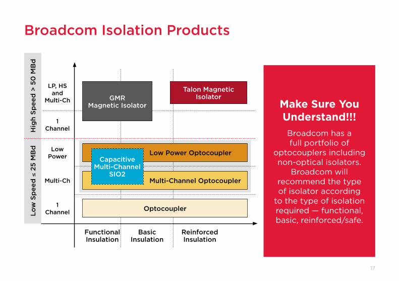
Broadcom Isolation Products
Make Sure You Understand!!!Broadcom has a full portfolio of
optocouplers including non-optical isolators.
Broadcom will recommend the type of isolator according
to the type of isolation required — functional, basic, reinforced/safe.
Talon Magnetic Isolator
Hig
h Sp
eed
> 5
0 M
Bd
Low Power Optocoupler
Multi-Channel Optocoupler
Optocoupler
Capacitive Multi-Channel
SIO2
GMR Magnetic Isolator
Functional Insulation
LP, HS and
Multi-Ch
1 Channel
1 Channel
Low Power
Multi-Ch
Basic Insulation
Reinforced Insulation

18
ACNT-Hxxx
Cree
page
(mm
)
Pack
age
Clea
ranc
e (m
m)
Inte
rnal
Clea
ranc
e (m
m)
IEC/
EN/D
INEN
607
47-5
-5V i
orm
(Vpe
ak)
UL 15
77V i
so (V
rms)
Cree
page
(mm
)
Pack
age
SO16
8-Pin
14.2mm SSO8
Wide Body
10-Pin
Stretched SO8(SSO-8)
Stretched SO12(SSO-12)
SO8
Stretched SO6(SSO-6)
SO5
Clea
ranc
e (m
m)
Inte
rnal
Clea
ranc
e (m
m)
IEC/
EN/D
INEN
607
47-5
-5V i
orm
(Vpe
ak)
UL 15
77V i
so (V
rms)
Photo IC
ACML
SO8
SO16
Digital Isolator
4.0 4.0 – – 2500
4.0 4.0 – – 2500
8.1 8.1 – – 2500
8.1 8.1 – – 5600
5.0 5.0 0.08 567 37504.5 4.9 0.08 567 2500
8.3 8.3 0.5 1230 5000
7.4 7.1 0.08 630 3750
8.0 7.4 0.5 891 3750/5000
14.2 14.2 0.5 2262 7500
8.0 8.0 0.08 1140 5000
13.0 13.0 2.0 2262 7500
8.0 7.0
ACPL-Pxxx
ACPL-Wxxx
ACSL
ACSL
ACPL-Hxxx
ACPL-Kxxx
ACPL-Cxxx
ACFL-xxxx
10.0 9.6 1.0 1414 5000
ACNVxxxx
0.08 891 3750
8.0 8.0 0.08 1140 5000
4.5 4.9 0.08 567 2500/3750
4.8 4.9 0.08 567 3750
8.0 7.0 0.08 891 3750
8.0 8.0 0.08 1140 5000
8.0 8.0 0.5 1414 5000
ACNWxxxx
Broadcom Optocoupler PackagesIEC Working Voltage
UL Withstand Voltage

19
Our Recommendations for Isolation TechnologiesFunctional
Transient VoltageFunctional
Continuous VoltageSafety
Transient VoltageSafety
Continuous Voltage
Optocoupler Thick Polymer insulation
Internal insulation construction exceeds package external flashover voltage
Thick insulation prevents partial discharge and space charge aging
Internal insulation construction exceeds package external flashover voltage
Reinforced internal insulation construction
Dominant long term potential failure mode is partial discharge — 100% safety test available
Magnetic Spin Coat Polyimide <25 um
ESD Hazard on exposed communication interfaces
E field stress readily activates space charge aging
Continuous high voltage exposure such as in motor inverter significantly ages insulation
Low energy ESD and repetitive overvoltage transients are capable of causing permanent damage to internal insulation
No reinforced internal insulation construction
Dominant long term failure mode is space charge aging not partial discharge — no appropriate safety test available.
Capacitive SIO2
ESD Hazard on exposed communication interfaces
E field stress readily activates SIO2 specific time dependent Breakdown
Continuous high voltage exposure such as in motor inverter significantly ages insulation
Low energy ESD and repetitive overvoltage transients are capable of causing permanent damage to internal insulation
No reinforced internal insulation construction
Dominant long term failure mode is SIO2 TBBD not partial discharge — no appropriate safety test available
Reinforced Planar Transformer Thick Polymer insulation
Internal insulation construction exceeds package external flashover voltage
Thick insulation prevents partial discharge and space charge aging
Internal insulation construction exceeds package external flashover voltage
Reinforced internal insulation construction
Dominant long term potential failure mode is partial discharge—100% safety test available
Go Be Careful Stop

For more information visit our website at: broadcom.com/optocouplers Broadcom, the pulse logo, connecting everything, and Avago Technologies, are among the trademarks of Broadcom. Copyright © 2016 Broadcom. All Rights Reserved. The term “Broadcom” refers to Broadcom Limited and/or its subsidiaries. For more information, please visit www.broadcom.com.AV00-0363EN 02.10.17