hall effect
DESCRIPTION
vvvTRANSCRIPT

Hall effectWhen a conductor is placed in a magnetic field which is perpendicular to the direction of current then a voltage difference (Hall voltage) is established at the ends of the conductor. This voltage is Hall voltage and this effect is called Hall effect. It was discovered by Edwin Hall in 1879.
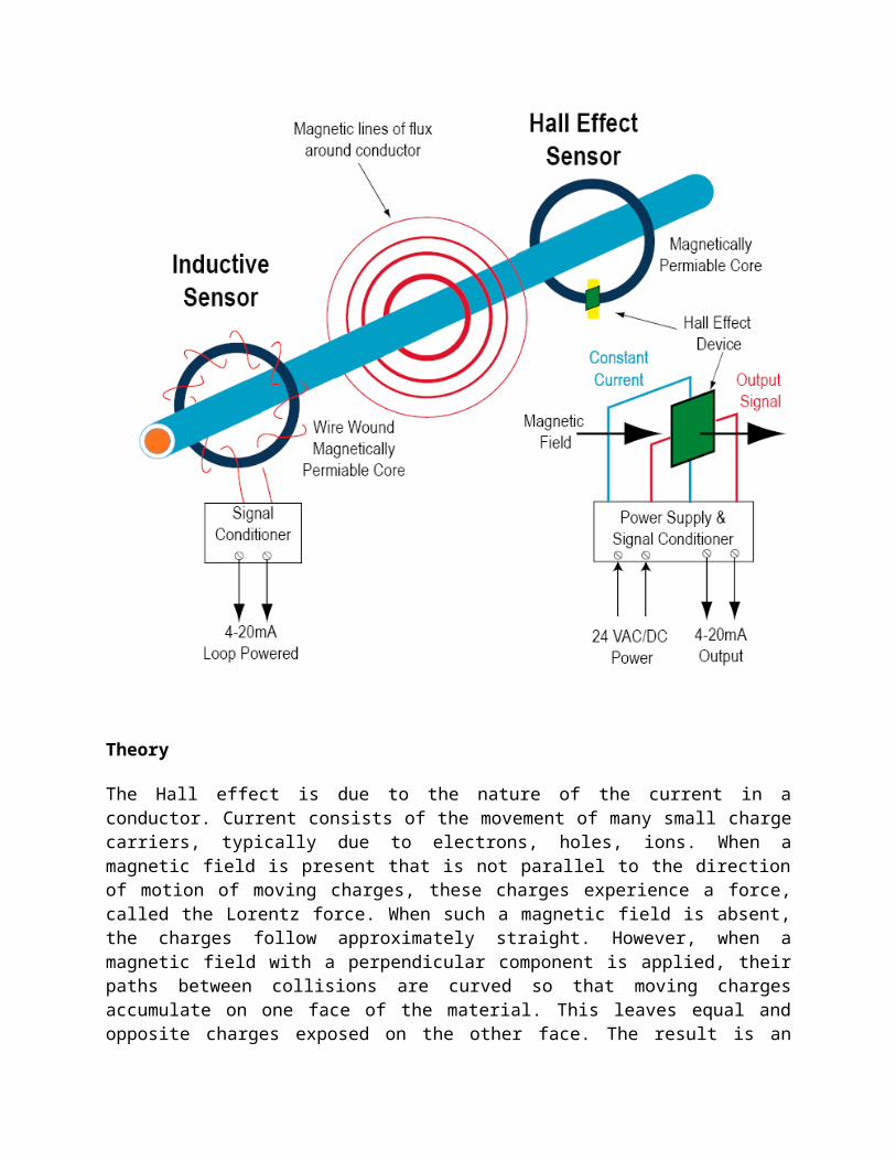
A Hall effect sensor is a transducer that varies its output voltage in response to a magnetic field. Electricity carried through a conductor will produce a magnetic field that varies with current, and a Hall sensor can be used to measure the current without interrupting the circuit. Typically, the sensor is integrated with a wound core or permanent magnet that surrounds the conductor to be measured.
Theory
The Hall effect is due to the nature of the current in a conductor. Current consists of the movement of many small charge carriers, typically due to electrons, holes, ions. When a magnetic field is present that is not parallel to the direction of motion of moving charges, these charges experience a force, called the Lorentz force. When such a magnetic field is absent, the charges follow approximately straight. However, when a magnetic field with a perpendicular component is applied, their paths between collisions are curved so that moving charges accumulate on one face of the material. This leaves equal and opposite charges exposed on the other face. The result is an asymmetric distribution of charge density. The separation of charge establishes an electric field that opposes the migration of further charge, so a steady electrical potential is established for as long as the charge is flowing.
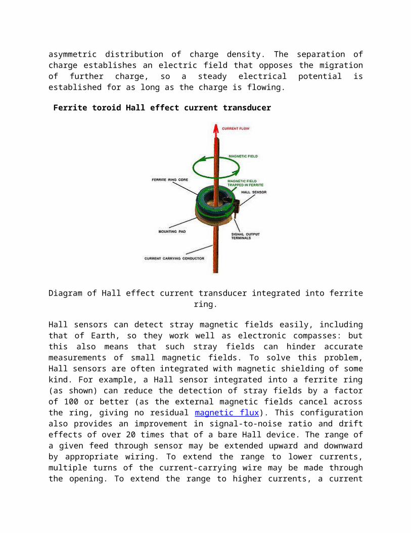
Ferrite toroid Hall effect current transducer
Diagram of Hall effect current transducer integrated into ferrite ring.
Hall sensors can detect stray magnetic fields easily, including that of Earth, so they work well as electronic compasses: but this also means that such stray fields can hinder accurate measurements of small magnetic fields. To solve this problem, Hall sensors are often integrated with magnetic shielding of some kind. For example, a Hall sensor integrated into a ferrite ring (as shown) can reduce the detection of stray fields by a factor of 100 or better (as the external magnetic fields cancel across the ring, giving no residual magnetic flux). This configuration also provides an improvement in signal-to-noise ratio and drift effects of over 20 times that of a bare Hall device. The range of a given feed through sensor may be extended upward and downward by appropriate wiring. To extend the range to lower currents, multiple turns of the current-carrying wire may be made through the opening. To extend the range to higher currents, a current
divider may be used. The divider splits the current across two wires of differing widths and the thinner wire, carrying a smaller proportion of the total current, passes through the sensor.
Hall effect sensor
Commonly used circuit symbol.