h2020 5g-transformer project grant no....
TRANSCRIPT

H2020 5G-TRANSFORMER Project
Grant No. 761536
First periodic report of the project
Abstract
This report constitutes the nonfinancial part of the Periodic Report to be delivered two
months after the end of the period (M15).

First periodic report of the project 2
H2020-761536
Document properties
Document number D7.3 Document title First periodic report of the project
Document responsible Carlos J. Bernardos (UC3M)
Document editor Carlos J. Bernardos (UC3M)
Editorial team Carlos J. Bernardos (UC3M), Thouraya Toukabri (ORANGE), Paola Iovanna (TEI), Thomas Deiß (NOK-N), Xi Li (NECLE), Juan Brenes (ATOS), Josep Mangues-Bafalluy (CTTC), Giulio Bottari (TEI)
Target dissemination level Public
Status of the document Final
Version 1
Production properties
Reviewers Thomas Deiß (NOK-N), Antonio de la Oliva (UC3M)
This document has been produced in the context of the 5G-TRANSFORMER Project.
The research leading to these results has received funding from the European
Community's H2020 Programme under grant agreement Nº H2020-761536.
All information in this document is provided “as is" and no guarantee or warranty is given
that the information is fit for any particular purpose. The user thereof uses the information
at its sole risk and liability.
For the avoidance of all doubts, the European Commission has no liability in respect of
this document, which is merely representing the authors view.

First periodic report of the project 3
H2020-761536
Table of Contents List of Figures ............................................................................................................... 4
List of Tables ................................................................................................................ 5
List of Acronyms ........................................................................................................... 6
Executive Summary ...................................................................................................... 9
1 Publishable Summary .......................................................................................... 10
1.1 Summary of the context and overall objectives of the Project ........................... 10
1.1.1 Project context ....................................................................................... 10
1.1.2 Project Objectives .................................................................................. 11
1.2 Work performed from the beginning of the project to the end of the period
covered by the report and main results achieved so far .................................... 11
1.3 Progress beyond the state of the art and expected potential impact (including the
socio-economic impact and the wider societal implications of the project so far)
12
2 Patents ................................................................................................................ 14
3 Dissemination activities ........................................................................................ 15
4 Explanation of the work carried out by beneficiaries and Overview of the progress
............................................................................................................................ 20
4.1 Objectives ........................................................................................................ 20
4.2 Explanation of the work carried per WP ............................................................ 29
4.2.1 WP1 ...................................................................................................... 29
4.2.2 WP2 ...................................................................................................... 43
4.2.3 WP3 ...................................................................................................... 47
4.2.4 WP4 ...................................................................................................... 55
4.2.5 WP5 ...................................................................................................... 64
4.2.6 WP6 ...................................................................................................... 76
4.2.7 WP7 ...................................................................................................... 85
4.3 Deliverables ..................................................................................................... 88
4.4 Milestones ........................................................................................................ 89
4.5 Exploitable Results ........................................................................................... 89
4.5.1 Exploitation on commercial products and PoC developed internally to the
companies .................................................................................................... 89
4.5.2 Exploitation on the realization of common platform among the 5G-
TRANSFORMER partners by means of testbed and demos ......................... 90
4.5.3 Exploitation on standards....................................................................... 91
4.6 Impact .............................................................................................................. 92
4.6.1 Progress towards the 5G-PPP Key Performance Indicators ................... 96
5 Update of the plan for exploitation and dissemination of result ............................. 99
6 Deviations from Annex 1 .................................................................................... 100
6.1 Tasks ............................................................................................................. 100
6.2 Use of resources ............................................................................................ 100
7 References ........................................................................................................ 101

First periodic report of the project 4
H2020-761536
List of Figures Figure 1: 5G-TRANSFORMER system architecture .................................................... 12
Figure 2: 5TONIC Infrastructure .................................................................................. 12
Figure 3: 5G-TRANSFORMER stakeholders mapping with the system
architecture .............................................................................................. 39
Figure 4: 5G-TRANSFORMER system architecture .................................................... 41
Figure 5: Hierarchy of monitoring services in 5G-TRANSFORMER architecture ......... 42
Figure 6: 5GT-MTP ARCHITECTURE ........................................................................ 45
Figure 7: The vertical slicer architecture ...................................................................... 52
Figure 8: Reference points of the 5GT-VS NBI ............................................................ 53
Figure 9: Workflow for VSD preparation ...................................................................... 54
Figure 10: 5GT-SO System Architecture – Building blocks and their interactions ......... 56
Figure 11: Functional architecture of the 5GT-SO monitoring platform ........................ 60
Figure 12: Federation as a domain unified by mutual trust [19] ................................... 62
Figure 13: 5GT-SO EBI/WBI reference points ............................................................. 63
Figure 14: 5TONIC Infrastructure (Partners involved: UC3M, Ericsson, NECLE) ........ 65
Figure 15: CTTC Testbed Infrastructure (Partners Involved: CTTC) ............................ 65
Figure 16: EURECOM Infrastructure (Partners Involved: EURECOM) ........................ 66
Figure 17: EURECOM MEC platform (Partners involved: EURECOM)........................ 66
Figure 18: ARNO Access (Partners involved: SSSA) .................................................. 67
Figure 19: ARNO Infrastructure (Partners involved: SSSA) ......................................... 67
Figure 20: Testbed integration plan (UC3M, SSSA, ERICSSON, NECLE,
EURECOM) .............................................................................................. 69
Figure 21: PoC Scheduling ......................................................................................... 75
Figure 22: 5G-TRANSFORMER Communication, Dissemination, and
Exploitation Plan (CoDEP) ..................................................................... 79
Figure 23: Mobile World Congress 2018 5G-TRANSFORMER Leaflet ....................... 81

First periodic report of the project 5
H2020-761536
List of Tables Table 1: Exhaustive list of 5G-TRANSFORMER use cases ........................................ 31
Table 2: KPIs definition ............................................................................................... 32
Table 3: Use case application scenarios and their associated KPIs ............................ 36
Table 4: KPis characterization and relevance ............................................................. 37
Table 5: Mapping between 5G-TRANSFORMER and 5G-PPP KPIs ........................... 38
Table 6: 5G-TRANSFORMER services ....................................................................... 40
Table 7: VSB for latency probe ................................................................................... 48
Table 8: Query VS Blueprints messages ..................................................................... 53
Table 9: Integrated Testbed Technologies (UC3M, SSSA, ERICSSON, NECLE,
EURECOM and CTTC) ............................................................................ 67
Table 10: 5G-TRANSFORMER Functional requirements (Atos, UC3M, CRF,
BCOM, NOK-N, SAMUR, TEI) .................................................................. 69
Table 11: 5G-TRANSFORMER PoCs ......................................................................... 71
Table 12: Communication articles ............................................................................... 84
Table 13: Communication presentation and lectures ................................................... 84
Table 14: Activity within 5G PPP CSA WGs ................................................................ 84
Table 15: 5G-TRANSFORMER and 5G PPP CSA WGs ............................................. 87
Table 16: Mapping between building blocks of the project the relevant partners’
PoCs, Products, Services and Solutions ................................................... 90
Table 17: Plan for demonstration and testbed ............................................................. 90
Table 18: 5G-TRANSFORMER contributions to standards ......................................... 91
Table 19: 5G-TRANSFORMER KPIs .......................................................................... 96

First periodic report of the project 6
H2020-761536
List of Acronyms Acronym Description 5GC 5G Core
5GT-MTP Mobile Transport and Computing Platform
5GT-SO Service Orchestrator
5GT-VS Vertical Slicer
AAA Authentication, Authorization, Accounting
AD Administrative Domain
AN Access Network
API Application Programming Interface
AppD Application Descriptor
BSS Business Support System
CAM Cooperative Awareness Messages
CAT Catalogue CIM Cooperative Information Manager
CN Core Network
CR Cloud Robotics
CSMF Communication Service Management Function
CU Central Unit
DB Database
DC Datacenter
DF Deployment Flavor
DoA Definition of Action
DU Distributed Unit
E2E End to end
EBI Eastbound Interface EM Element Management
EPC Evolved Packet Core
EPCaaS EPC as a Service
ETSI European Telecommunication Standardization Institute
GRE Generic Routing Encapsulation
GS Group Specification
HSS Home Subscriber Server
IaaS Infrastructure as a Service
ICT Information and Communication Technology
IETF Internet Engineering Task Force
IFA Interfaces and Architecture
KPI Key Performance Indicator
LC Lifecycle LCid Lifecycle Operation Occurance Id
LCM Lifecycle Management
M&E Media and Entertainment
M(V)NO Mobile (Virtual) Network Operator
MANO Management and Orchestration
MEC Multi-access Edge Computing
MEO Multi-access Edge Orchestrator
MEP Multi-access Edge Platform
MILP Mixed Integer-Linear Programming
MIoT Massive Internet of Things
MLPOC Multiple Logical Point of Contact
MME Mobility Management Entity
First periodic report of the project 7
H2020-761536
MNO Mobile Network Operator
MON Monitoring
MVNE Mobile Network Enabler
NaaS Network as a Service NBI Northbound Interface
NF Network Function
NFP Network Forwarding Path
NFV Network Function Virtualization
NFVI Network Functions Virtualisation Infrastructure
NFVIaaS NFVI as a Service
NFV-NS NFV Network Service
NFV-NSaaS Network Service as a Service
NFV-NSO Network Service Orchestrator
NFVO NFV Orchestrator
NFVO-RO Resource Orchestrator
NGMN Next Generation Mobile Networks NS Network Slice
NSaaS Network Slice as a Service
NSD Network Service Descriptor
NS-DF Network Service Deployment Flavor
NSI Network Slice Instance
NSMF Network Slice Management Function
NS-OE NFV-NS Orchestration Engine
NSSI Network Slice Subnet Instance
NSSMF Network Slice Subnet Management Function
NST Network Slice Template
OLE Onsite Live Experience
ONAP Open Network Automation Platform OSM Open Source MANO
OSS Operating Support System
OTT Over the top
PM Performance Management
PMON Performance Monitoring
PNF Physical Network Function
PNFD PNF Descriptor
PoC Proof of Concept
PoP Point of Presence
QoS Quality of Service
RAM Resource Advertisement Management
RAN Radio Access Network REST Representational State Transfer
RM Resource Management
RMM Resource Monitoring Management
RNIS Radio Network Information Service
RO Resource Orchestration
RO-EE RO Execution Entity
RO-OE RO Orchestration Engine
RSU Road-Side Unit
RTT Round Trip Time
SAP Service Access Point
SBI Southbound Interface
SDK Software Development Kit

First periodic report of the project 8
H2020-761536
SDO Standard Developing Organisation
SLA Service Level Agreement
SLPOC Single Logical Point of Contact
SLPOC-F Single Logical Point of Contact for Federation SME Small and Medium Enterprises
SO Service Orchestrator
SPGW-C Serving/Packet Data Network Gateway Control Plane
SPGW-U Serving/Packet Data Network Gateway User Plane
TD Technology Domain
TETRA Terrestrial Trunked Radio
TMVS 5G-TRANSMORMER Managed Vertical Service
TN Transport Network
TOSCA Topology and Orchestration Specification for Cloud Applications
TRF 5G-TRANSFORMER Resource Federation
TSC 5G-TRANSFORMER Service Consumer
TSF 5G-TRANSFORMER Service Federation TSP 5G-TRANSFORMER Service Provider
TUVS 5G-TRANSFORMER Unmanaged Vertical Service
UC Use Case
UE User Equipment
UPF User Plane Function
VA Virtual Application
vEPC virtual Evolved Packet Core
VIM Virtual Infrastructure Manager
VL Virtual Link
VLAN Virtual Local Area Network
VM Virtual Machine
VNF Virtual Network Function VNFD VNF Descriptor
VNFFG VNF Forwarding Graph
VNFFGD VNFFG Descriptor
VSD Vertical Service Descriptor
VSI Vertical Service Instance
WAN Wide Area Network
WBI Westbound Interface
WIM Wide area network Infrastructure Manager
WP Workpackage
YAML YAML Ain't Markup Language

First periodic report of the project 9
H2020-761536
Executive Summary The present deliverable called D7.3 presents the Part B of the First Periodic Report that
will be delivered before 28th of August 2018. It mainly includes the information of the
scientific work carried out between 1st of June 2017 and 30th of June 2018. It is important
to highlight that the deadline of D7.3 is the 30th of June 2018, the final data for use of
resources is still not available at the end of June. The full financial information will be
included in the First Periodic Report in August.
This document includes the Publishable Summary, patents and dissemination activities
that will be completed in the Participant Portal too, a description of the technical work
carried out by beneficiaries and overview of the progress in the first 13 months of the
project, including the objectives, the work performed by work package, the deliverables
and milestones, the impact and finally the deviations of the project.

First periodic report of the project 10
H2020-761536
1 Publishable Summary
1.1 Summary of the context and overall objectives of the Project
1.1.1 Project context
"5G-TRANSFORMER: 5G Mobile Transport Platform for Verticals" is a 30-month
collaborative project. The aim of the project is to apply SDN/NFV to transform current
rigid mobile transport networks into a 5G dynamic system able to manage networking
and computing resources tailored to the specific needs of vertical industries, such as
eHealth, automotive, media, and industry 4.0. Additionally, network slicing, multi-access
edge computing (MEC) and federation are seen as key enablers to allow such
transformation. 5G-TRANSFORMER defines three main architectural building blocks:
the Vertical Slicer (5GT-VS), for supporting the creation and management of slices for
verticals; the Service Orchestrator (5GT-SO), for end-to-end service orchestration and
federation of resources and services from multiple domains, and the Mobile Transport
and Computing Platform (5GT-MTP), acting as the underlying fronthaul and backhaul
transport network.
Main innovations delivered by the project are:
5GT-VS
• 5GT-VS architecture and interfaces, allowing verticals, with no required expertise
on service orchestration: (i) to describe vertical services by selecting a Vertical
Service Blueprint (VSB) from a catalogue; (ii) to customize them into Vertical
Service Descriptors (VSD) and to instantiate vertical services; and (iii) to control
their lifecycle.
• Arbitrator and SLA management for intra- and inter-vertical priority handling.
• Slice management and VSD/NSD Translator for mapping a vertical service
descriptor to a slice and its corresponding network service descriptor.
5GT-SO
• 5GT-SO architecture and interfaces, aligned with ETSI NFV, including: (i) a
Catalogue Manager and available Network Service and VNF repository, (ii) 5GT-
MTP abstracted resources repository, (iii) network service instance repository;
(iv) a network function virtualization orchestrator (NFVO) orchestrating both
resources and services across multiple domains; (v) VNF Managers (VFNMs);
and (vi) a monitoring platform.
• Service/resource orchestration and federation algorithms, allowing optimized
actions based on different metrics and targeting resiliency, fault-tolerance and
flexibility.
5GT-MTP
• 5GT-MTP architecture, integrating MEC and decoupling of virtual infrastructure
manager (VIM) from the NFVO and VNFMs.
• Ability to compose a connectivity service and expose it to the 5GT-SO.
• Resource abstraction using a single logical point of contact (SLPOC).
First periodic report of the project 11
H2020-761536
1.1.2 Project Objectives
Main objectives of the project are:
• To design a reference architecture for the 5G-TRANSFORMER platform,
encompassing a flexible Mobile Transport and Computing Platform, a Service
Orchestration platform, and a resource slicing platform for verticals.
• To design scalable algorithms for efficient 5G-TRANSFORMER service/resource
orchestration: backhaul/fronthaul networking, computing, and storage.
• To support orchestration of end-to-end services across federated domains.
• 5G-TRANSFORMER key concepts validation and proof of concept.
• Communication, Dissemination, and exploitation (incl. standardization) of 5G-
TRANSFORMER.
1.2 Work performed from the beginning of the project to the end of the period covered by the report and main results achieved so far
During this period, the project has focused on designing the 5G-TRANSFORMER
architecture, developing the key concepts behind a true SDN/NFV/MEC mobile transport
and computing platform capable of offering slices tailored to the specific needs of
disparate vertical industries. The work in the project has been divided into 5 technical
Work Packages (WPs). WP1 is in charge of defining the set of use cases and scenarios
to be used to challenge the architecture of the system. WP1 is also in charge of designing
the baseline architecture of 5G-TRANSFORMER (see Figure 1), which is aligned with
the SDOs relevant in the area, mostly ETSI NFV and MEC. WP2 is in charge of the
design and development of the 5GT-MTP, ensuring that it is capable of aggregating
different technology domains and fulfil the requirements for different verticals. WP2
results during this period include the initial design of the 5GT-MTP architecture, starting
from the analysis of the vertical requirements and use cases, integrating MEC, providing
abstraction of resources and connectivity services to the 5GT-SO. WP3 is responsible of
the design and development of the 5GT-VS. During the first reporting period, an initial
design of the 5GT-VS architecture has been performed, with a focus on two aspects: (i)
the definition of VSBs and how they are translated into VSDs that can be then converted
into NSDs so they can be instantiated by the 5GT-SO, and (ii) the initial design of
arbitration algorithms guaranteeing the availability of resources to high-priority vertical
services. WP4 is in charge of the design and implementation of the 5GT-SO. In this first
reporting period, an initial design of the 5GT-SO architecture has been released, based
on the ETSI NFV specifications, and providing resource and service orchestration, both
within one single administrative domain and among several domains (federation). WP4
has also worked on the first release of the 5G-T monitoring architecture. The main goal
of WP5 is to integrate the components designed in WP2, WP3 and WP4 and to validate
experimentally that the 5G-T architecture is capable of deploying slices fulfilling the
requirements from various verticals. Main work of WP5 during this period has been the
design and setup of the interconnection of the different test sites (as one example, the
5TONIC one is shown in Figure 2), as well as a first integration plan towards the
implementation of several proofs of concept (PoCs) around the vertical use cases
considered in the project.

First periodic report of the project 12
H2020-761536
FIGURE 1: 5G-TRANSFORMER SYSTEM ARCHITECTURE
FIGURE 2: 5TONIC INFRASTRUCTURE
1.3 Progress beyond the state of the art and expected potential impact (including the socio-economic impact and the wider societal implications of the project so far)
The 5G-TRANSFORMER project targets innovations around the three main components
of the project architecture: (1) Vertical slicer: offering a powerful, yet simple and flexible,
interface to verticals to describe and consume slices tailored to their needs; (2) Service
orchestrator: capable of instantiating and orchestrating the network services required by
the vertical slices, including federation mechanisms between different administrative

First periodic report of the project 13
H2020-761536
domains; and (3) Mobile transport and computing platform, integrating compute, storage
and networking resources, including MEC. All these innovations are combined together
into an architecture framework that takes into account both technical and techno-
economic requirements from the stakeholders of the value chain, namely operators,
vendors and service providers.
All the above innovations are driven primarily by the need to make the future 5G networks
more flexible and capable of adapt to offer slices capable of simultaneously meeting the
disparate requirements of different verticals, whilst guaranteeing cost-efficient use of the
resources. This results into a direct socio-economic impact, through lower cost and
higher efficiency for the infrastructure stakeholders (operators, vendors, and service
providers), and the end user customer in terms of better service (quality and ubiquitous
access), and lower bills. The overall society will also see the benefit of driving the future
transport network towards more flexibility and cost-efficiency, whilst supporting the
various services envisioned in future 5G. In addition, the innovations from the 5G-
TRANSFORMER project are expected to give the industrial companies (large, medium
and small) in the project consortium and the extended European 5G-PPP community a
privileged position and competitive advantage in the European and global markets
through new generations of mobile networks. An exploitation plan is being defined to
assess the possible impact on the product and services roadmaps of the vendors and
operators involved in the project.
In order to ensure wide-reach of the innovations developed in the project, the consortium
members have been very active in disseminating the project concept and early results to
the European community (inside and outside 5G-PPP) and the wider international
research and industrial community. The consortium has promoted the envisioned
concepts and R&D achievements through various types of dissemination activities. In
particular, the project has successfully delivered:
• 37 scientific publications.
• 6 (Co-)organized workshops.
• 6 demonstrations including at flagship events such as EuCNC 2018.
• 16 standard contributions.

First periodic report of the project 14
H2020-761536
2 Patents The project has registered two Intellectual Property Rights, one by SSSA and one by
IDCC:
• “Metodo per il ripristino della connessione di una rete di telecomunicazioni”
(“Method for restoring the connection of a telecommunications network”).
Submission Number: 102018000003571. Filed: 14 March 18.
• “Methods for advertising and selecting network slices dual-connectivity and multi-
subscriber scenarios in 5G”, PCT Patent Application No 82707182, Filed: 08
August 2017.

First periodic report of the project 15
H2020-761536
3 Dissemination activities This section describes the dissemination activities of 5G-TRANSFORMER during the
first year. The dissemination activities follow the plan described in D6.1 [21], that is,
publication of research results (Table 1), Technology Demonstration (Table 2), Academic
activities (Table 3) and Organization and Participation in events (Table 4). A modification
to the initial plan has to be highlighted. It is related to the participation to events in order
to give technical talks related on 5G-TRANSFORMER topics, such as keynote, panels
and technical presentation. Table 5 summarizes this new activity.
The first year of the project was very rich in terms of dissemination activities. Notably, 37
scientific publications have been published in peer reviewed journals, conferences and
workshops (Table 1); 6 in Journals, 20 at conferences and 11 at workshops. Some of
these publications are joint publications with other projects. Further, 5G-
TRANSFORMER partners have participated to the organization of very successful
events and workshops (Table 3) co-located with prestigious conferences. For example,
we received positive feedback from COMPASS workshop attendees based on the poll
circulated to the attendees. Most of these events were co-organized jointly with other
projects.
Regarding the academic activities, several students have been enrolled to work on 5G-
TRANSFORMER topics; 5 PhD, 2 Masters, and 2 Bachelor students have been enrolled
during the first year.
Although it is the first year of the project, partners have made strong efforts to start
demonstrating the 5G-TRANSFORMER results. In addition to an INFOCOM and Mobile
World Congress demo, three demos were prepared for EuCNC 2018 on different topics
treated in 5G-TRANSFORMER, and one was performed to the PSA group at 5TONIC
premises.
TABLE 1: PUBLICATIONS (J: PEER-REVIEWED JOURNAL, C: PEER-REVIEWED
CONFERENCE, W: PEER-REVIEWED WORKSHOP)
Title Venue
J WizHaul: On the Centralization Degree of Cloud RAN Next Generation Fronthaul
IEEE Transactions on Mobile Computing (TMC), February 2018
J Efficient Caching through Stateful SDN in Named Data Networking
Transactions on Emerging Telecommunications Technologies, Jan. 2018
J Virtualization-based evaluation of backhaul performance in vehicular applications
Computer Networks, April 2018
J 5G-TRANSFORMER: Slicing and Orchestrating Transport Networks for Industry Verticals
IEEE Communications Magazine, accepted in 2018
J On Enabling 5G Automotive Systems Using Follow Me Edge Cloud Concept
IEEE Transactions on Vehicular Technology (TVT), accepted 2018
J Scheduling Advertisement Delivery in Vehicular Network
IEEE Transactions on Mobile Computing (TMC), accepted in 2018
C Sharing of Crosshaul Networks via a Multi-Domain Exchange Environment for 5G Services
IEEE NetSoft 2017

First periodic report of the project 16
H2020-761536
C A Simulation-based Testbed for Vehicular Collision Detection
IEEE VNC 2017
C Software Defined 5G Converged Mobile Access Networks: Energy Efficiency Considerations
Asia Communications and Photonics Conference, 10 - 13 November 2017, The Garden Hotel, Guangzhou, Guangdong China
C SDN-enabled Latency-Guaranteed Dual Connectivity in 5G RAN
Asia Communications and Photonics Conference, 10 - 13 November 2017, The Garden Hotel, Guangzhou, Guangdong China
C Network Orchestration in Reliable 5G/NFV/SDN infrastructures
19th International Conference on Transparent Optical Networks (ICTON) 2017, Girona, Spain
C Requirements for 5G fronthaul 19th International Conference on Transparent Optical Networks (ICTON) 2017, Girona, Spain
C Network Orchestration in Reliable 5G/NFV/SDN infrastructures
19th International Conference on Transparent Optical Networks (ICTON) 2017, Girona, Spain
C Virtualized eNB latency limits 19th International Conference on Transparent Optical Networks (ICTON) 2017, Girona, Spain
C Joint VNF Placement and CPU Allocation in 5G
IEEE International Conference on Computer Communications (INFOCOM) 15-19, April 2018, Honolulu, USA
C FluidRAN: Optimal vRAN/MEC Orchestration
IEEE International Conference on Computer Communications (INFOCOM) 15-19, April 2018, Honolulu, USA
C Present-day verticals and where to find them: A data-driven study on the transition to 5G
IEEE WONS 2018
C Service migration versus Service replication in Multi-access Edge Computing (MEC)
IEEE IWCMC 2018, June 24-29, Cyprus
C Orchestrating Lightpath Adaptation and Flexible Functional Split to Recover Virtualized RAN Connectivity
OFC 2018, March 11-15, 2018, San Diego, CA, USA
C Software Defined 5G Converged Access as a viable Techno-Economic Solution
OFC 2018, March 11-15, 2018, San Diego, CA, USA
C Enabling Flexible Functional Split through software 5G converged access
IEEE ICC 2018, Kansas City, MO, USA
C Performance analysis of C-V2I-based Automotive Collision Avoidance
IEEE WoWMOM 2018, Chania, Greece
C Optimization-in-the-Loop for Energy-Efficient 5G
IEEE WoWMOM 2018, Chania, Greece
C Experimental SDN Control Solutions for Automatic Operations and Management of 5G Services in a Fixed Mobile Converged Packet-Optical Network
IEEE ONDM 2018

First periodic report of the project 17
H2020-761536
C Enabling Vertical Industries Adoption of 5G Technologies: A Cartography of Evolving Solutions
EuCNC 2018, Ljubljana, Slovenia
C The Vertical Slicer: Verticals’ Entry Point to 5G Networks’
EuCNC 2018, Ljubljana, Slovenia
W Orchestrating Lightpath Adaptation and Flexible Functional Split to Recover Virtualized RAN Connectivity (poster)
URLLC 2017
W WizHaul: An Automated Solution for vRAN Deployments Optimization
WSA 2018 - ITG workshop on smart antennas, March 2018
W Service Orchestration and Federation for Verticals
IEEE WCNC COMPASS workshop, April 2018, Barcelona, Spain
W 5G Mobile Transport and Computing Platform for Verticals
IEEE WCNC COMPASS workshop, April 2018, Barcelona, Spain
W Network Slices For Vertical Industries IEEE WCNC COMPASS workshop, April 2018, Barcelona, Spain
W Impact of RAN Virtualization on Fronthaul Latency Budget: An Experimental Evaluation
International Workshop on 5G Test-Beds and Trials - Learnings from implementing 5G (5G--Testbed 2017) co-located with Globecom 2017, Singapore
W Understanding QoS applicability in 5G transport networks
WS3: Second Edition of the Workshop on Control and Management of Vertical Slicing including the Edge and Fog Systems, IEEE International Symposium on Broadband Multimedia Systems and Broadcasting, Valencia, June 2018
W Multi-domain VNF mapping algorithms
WS3: Second Edition of the Workshop on Control and Management of Vertical Slicing including the Edge and Fog Systems, IEEE International Symposium on Broadband Multimedia Systems and Broadcasting, Valencia, June 2018
W Towards a resilient OpenFlow channel through MPTCP
WS3: Second Edition of the Workshop on Control and Management of Vertical Slicing including the Edge and Fog Systems, IEEE International Symposium on Broadband Multimedia Systems and Broadcasting, Valencia, June 2018
W Arbitration Among Vertical Services Accepted in PIMRC 2018 workshop ‘Vertical-Oriented Service Programmability: Design and Optimization of 5G Cell-Less Networks (5G Cell-Less Nets)’
W Resource Orchestration of 5G Transport Networks for Vertical Industries
Accepted in PIMRC 2018 workshop ‘Vertical-Oriented Service Programmability: Design and Optimization of 5G Cell-Less Networks (5G Cell-Less Nets)’
First periodic report of the project 18
H2020-761536
TABLE 2: TECHNOLOGY DEMONSTRATIONS
Title Event Demo of the initial heterogeneous network part of the MTP
Mobile World Congress’18
OVNES: Demonstrating 5G Network Slicing Overbooking on Real Deployments
IEEE INFOCOM 2018
Robotic Control Leveraging a Radio Network Information Service (RNIS)
EuCNC 2018
Orchestrating entertainment network service deployment in a hybrid cloud with Cloudify
EuCNC 2018
Creating a media-oriented slice through the 5G-TRANSFORMER vertical slicer
EuCNC 2018
5G network slices for mobile communication services
EuCNC 2018
5G Edge Assisted Robotics Trial 5TONIC internal demonstration to PSA group
TABLE 3: ACADEMIC ACTIVITIES
Title Level Status
eNB split functions (Distributed Unit --- DU --- and Central Unit --- CU) virtualization and its impact on fronthaul available latency budget.
PhD Ongoing
Resource Orchestration in Virtualized Networks through SDN-enabled OpenStack
PhD Ongoing
Software Defined Networking based mobility management in small cells
PhD Ongoing
Mechanisms to integrate and enhance NFV and MEC PhD Ongoing
Design and optimization of solutions for discovery and federation for NFV in edge & fog scenarios
PhD Ongoing
Multi-domain VNF mapping algorithms Master Defended
Development of a RNIS API based on Publish/subscribe using OAI
Master Ongoing
Análisis de un orquestador NFV/SDN para redes de operador Bachelor Defended
Service Function Chaining en NFV: Evaluación práctica con OpenStack
Bachelor Defended
TABLE 4: ORGANIZATION OF EVENTS
Title Event
2nd Workshop on Control and Management of Vertical Slicing including the Edge and Fog Systems (COMPASS) (under preparation)
Co-located with IEEE International Symposium on Broadband Multimedia Systems and Broadcasting, June 6th – 8th, 2018, Valencia, Spain. Jointly organized with 5G-CORAL and 5GEx projects
Multi-provider, multi-vendor, multi-player orchestration: from distributed cloud to edge and fog environments in 5G (under preparation)
Co-located with EUCNC 2018, workshop takes place on 18 June 2018, 09:00-18:00
1st Workshop on Control and Management of Vertical Slicing including the Edge and Fog Systems (COMPASS)
Co-located with IEEE Wireless Communications and Networking Conference (WCNC) 2018, April,

First periodic report of the project 19
H2020-761536
Barcelona. Jointly organized with 5G-CORAL project
Organization of the “5G technology for automotive domain” workshop in Turin including industrial and academic presentations
Industry-academia workshop organized in FCA, July 2017
Co-organization of a special session on 5G Mobile Transport Networks jointly with the 5G-Crosshaul project
Organized at Wireless World Research Forum (WWRF) 39 meeting in Barcelona, October 2017. More information available at: http://wwrf39.ch/WWRF.html
Organization of IEEE VNC 2017 2017 IEEE Vehicular Networking Conference (VNC), Nov. 2017, Torino
TABLE 5: PARTICIPATION TO EVENTS
Title Type Event
Connected Car and Digital Transformation
Keynote IEEE Vehicular Networking Conference (VNC), Nov. 2017, Torino, Italy
5G and Verticals: The Connected and Automated Driving (CAD) Case
Panel IEEE Wireless Communications and Networking Conference (WCNC), April 2018, Barcelona, Spain
MVNOs World congress Talk MVNOs World Congress, April 2018
RS-FCN: Resource Slicing for Future Clouds and Networks
Talk IEEE International Conference on Computer Communications (INFOCOM), April 2018, Honolulu, USA
All conference and workshop publications have been presented in their corresponding venue
Talk Several international conferences and workshops (see publications table)

First periodic report of the project 20
H2020-761536
4 Explanation of the work carried out by beneficiaries and Overview of the progress
4.1 Objectives
This section is devoted to present the progress towards the fulfilment of the project
objectives. For each of the objectives identified in the Description of Action (DoA), we
present the details on how are they being tackled technically and by which WP.
Objective 1 5G-TRANSFORMER key concept validation and proof of concept
Description Demonstration and validation of 5G-TRANSFORMER technology components designed and developed in WP1, WP2, WP3 and WP4, and integrated in WP5 in an E2E 5G testbed.
R&D Topics WP/task Details
Experimental validation of 5G-TRANSFORMER components and integrated platform.
WP5/T5.1
• Design, initial deployment and configuration of interconnection of the trial sites involved in the future validation of 5G-TRANSFORMER components. Described in D5.1 [6].
• Selection of use cases and Proof of Concept (PoCs) to be implemented and tested.
WP5/T5.2
• Initial planning of software components’ features needed at each integration stage, according to the requirements of the PoCs.
WP5/T5.3
WP6/T6.2
• 4 demos showing initial releases of the 5G-TRANSFORMER architecture components shown at EuCNC 2018.
Verification WP/task Details
Demonstration of three verticals, namely automotive, eHealth and media distribution, over 5G-TRANSFORMER platform, having diverse requirements.
WP5/T5.1
WP5/T5.2
WP5/T5.3
• Initial demonstrations of early releases of 5G-TRANSFORMER components during EuCNC 2018.
Demonstration integrating two federated domains.
WP5/T5.1
WP5/T5.2
• Interconnection of 5G-TRANSFORMER sites (required for future PoCs involving federation).
• Identification of the federation requirements posed by the different vertical-oriented PoCs.
Performance evaluation of algorithms in the field fulfilling vertical SLAs as well as 5G-relevant KPIs on throughput, latency and energy.
WP5/T5.1
WP5/T5.2
• The demos shown at EuCNC 2018 include a qualitative evaluation of the vertical SLAs. D5.1 [6] includes a roadmap to deploy the PoCs of the corresponding use cases including their evaluation.

First periodic report of the project 21
H2020-761536
Exhibiting at flagship events such as MWC 2018/19.
WP5/T5.3
• 4 demonstrations performed at EuCNC 2018.
Objective 2 Design a reference architecture for 5G-TRANSFORMER platform
Description Design a baseline architecture of the 5G-TRANSFORMER system that will serve as a reference for the technical work of WP2, WP3, WP4 and WP5. A first analysis of use-cases relevant to vertical sectors will set the requirements posed in the architectural design. The architecture will be validated through a techno-economic study and thorough implementation.
R&D Topics WP/task Details Analysis of 5G use-cases relevant for verticals and their requirements.
WP1/T1.1
• An analysis of the vertical scenarios from different perspectives, providing a robust and coherent set of requirements for the architecture design has been performed and reported in D1.1 [1]. The requirements are refined and complemented in D1.2 [2].
5G-TRANSFORMER reference architecture design.
WP1/T1.2
• A description of the initial system design of the 5G-TRANSFORMER architecture, including the design of the main building blocks and the interfaces among them, as well as the interface towards the verticals is reported in D1.2 [2]. Additionally, it defines the high-level workflows among the building blocks for a set of basic service operations, showing the required interactions among the different building blocks on the related interfaces.
Study on techno-economic impact of 5G-TRANSFORMER
WP1/T1.3
• The task devoted to this started in M13. Initial analysis of results from previous related projects such 5GEx is being analysed.
Verification WP/task Details
Report a reference architecture design for 5G-TRANSFORMER.
WP1/T1.2
• Reference architecture design is included in D1.2 [2].
Report on techno-economic study.
WP1/T1.3
• Ongoing work (T1.3 just started in M13.
Implementation of the architecture and verification of the contribution to KPI.
WP1/T1.2
WP2 WP3 WP4 WP5
• Ongoing work planning the implementation of the 5G-T components, organized in different releases, to provide the functionality required by the vertical-oriented PoCs. First release almost ready for some components, such as the 5GT-VS.
Objective 3 Design a flexible Mobile Transport and Computing Platform (MTP)
Description Design 5G-TRANSFORMER MTP by departing from 5G-Crosshaul MANO and adding native support for MEC along with transport control and virtualization technologies to flexibly place and move VNFs across the MTP.
R&D Topics WP/task Details
Evolution of 5G-Crosshaul to
WP2/T2.1
• The 5GT-MTP design extends the 5G-Crosshaul transport solution with MEC and dynamic

First periodic report of the project 22
H2020-761536
encompass MEC, optimization of flexible placement of VNFs in a multi-tenant scenario.
WP2/T2.2
creation of slices and placement of VNFs to take into account the needs of vertical industries, as reported in D2.1 [3].
• The 5GT-MTP is able to support the deployment of MEC applications and services providing the following features: (i) advertisement of MEC hosts, including their characteristics (locations, capabilities, network connectivity to RAN and WIMs); (ii) deployment of MEC applications and configuration of the related traffic steering; (iii) advertisement of MEC services running in each MEC hosts; (iv) support of network interfaces towards the RAN to enable MEC services like Radio Network Information Service (RNIS). This is reported in D2.1 [3].
Multi-level, multi-criteria abstraction and network clustering for hierarchical SDN/NFV control.
WP2/T2.1
WP2/T2.2
• The 5GT-MTP architecture supports multi-layer or multi-technology network infrastructures. In this case, SDN Controllers can be deployed in a hierarchical model to handle the heterogeneity of the technological domains through dedicated child controllers. In D2.1 [3], a model of abstraction have been reported to deal with transport network based on hierarchical SDN as well.
Dynamic (de-)centralization and placement of VNFs (mobile system middleware) through composition/decomposition of VNF chains.
WP2/T2.2
• The 5GT-MTP provides a suitable abstraction (reported in D2.1 [3]) allowing the dynamic placement of VNF that can be centralized or decentralized according the requirements of the vertical service.
Design an SDN/NFV architecture that can cope with multiple types of agents (e.g., wireless agents, packet system, optical agents).
WP2/T2.1
• The 5GT-MTP designed architecture supports heterogeneous Technological Domains, as described in D2.1 [3].
Abstract information model to export parameters of MTP to the orchestrators serving the verticals (e.g., based on Transport SDN API).
WP2/T2.2
• Depending on the use case, the 5GT-MTP may offer different levels of resources abstraction to the 5GT-SO via the 5GT-MTP resource abstraction component, which in turn forwards the 5GT-SO requests to the right entity accordingly (as single point of contact): VIM/WIM, VNFM or PNF, or NFVO.

First periodic report of the project 23
H2020-761536
Verification WP/task Details
Develop and demonstrate a proof-of-concept prototype of the MTP (TRL 3).
WP2 • Ongoing work implementing the 5GT-MTP components.
Objective 4 Design scalable algorithms for efficient 5G-TRANSFORMER resource orchestration: backhaul/fronthaul networking, computing, and storage
Description Develop and evaluate integrated management and control algorithms for resource orchestration that ensure an appropriate service delivery and optimal resource utilization, despite dynamically changing traffic loads, available computational and network resources, wireless link fluctuations, flexible functional RAN splits and heterogeneous QoS requirements.
R&D Topics WP/task Details
Scalable orchestration algorithms for dynamic joint optimization of routing and RAN/MTP/Core function placement.
WP2/T2.3
• An algorithm to optimize the placement of VNF considering joint optimization of routing, RAN/5GT-MTP/Core has been defined. It is based on the abstraction methods defined in T2.2 that aims at providing scalable solutions and reducing the dependency of the technological specific characteristics of the resources (e.g., transport, radio).
Novel 5G-capable routing and traffic engineering algorithms using latency and jitter, wireless transport interference, user mobility, etc.
WP2/T2.2
WP2/T2.3
• Innovative abstraction methods have been defined and reported in D2.1 [3] to enable the implementation of algorithms allowing to perform routing and traffic engineering using values as latency, jitter for optimization. Such methods are based on a procedure that translates the technological specific parameters (e.g., wavelengths, etc.) of each domain in common parameters such as jitter and latency, in order to provide a homogeneous representation of the resources according to graph that enable the design on optimization algorithm that will be defined as next step.
Novel capacity and Quality of Experience (QoE) optimization techniques required for verticals, optimization of MEC server location and server configuration, congestion-aware caching.
WP2/T2.3
• Ongoing work based on the 5G-MTP architecture and abstraction models defined in D2.1 [3]
Techniques for path provisioning, mobility
WP2/T2.3
• Algorithms defined for VNF placement. Further work will be done in the next reporting period.

First periodic report of the project 24
H2020-761536
management, placement and re-location of VNFs based on multi-criteria optimization. Techniques to support scalable and efficient distributed computing across heterogeneous vertical sectors.
WP2/T2.3
• Ongoing work based on architecture defined in T2.1.
Verification WP/task Details
Simulative or analytical proof of scalability, throughput, latency, and computational performance of resource management algorithms.
WP2/T2.3
• Design and evaluation of an algorithm aiming at minimizing the overall cost providing the most optimal VNF placement in a multiple data-center scenario.
• Design, validation and evaluation of an on-line algorithm to provide quality-enabled VNFFG in remote data-centers interconnected though a multi-layer (packet over optical) network infrastructure.
Prototype at least one algorithm on top of 5G-Crosshaul data plane.
WP2 • Ongoing work implementing the 5GT-MTP components.
Objective 5 Design a resource slicing platform for verticals (vertical slicer)
Description Design and develop slicing techniques to address heterogeneous vertical-tailored requirements in a common cloud plus MTP infrastructure, including connectivity and vertical functions.
R&D Topics WP/task Details
Study of dynamic resource partitioning techniques for connectivity, computing and storage resources in an integrated core/MTP network.
WP3/T3.2
• The arbitration component in the 5GT-VS assigns resources among vertical service instances. Dynamic reassignment is done in case of service instantiation, modification, and termination, and in case of changes of resource availability.
Dynamic and flexible placement of vertical functions.
WP4/T4.1
• One of the main tasks of the 5GT-SO is the judicious placement of vertical functions, once translated into a network service by 5GT-VS. The system design and the algorithmic framework to achieve this objective are explained in D4.1 [5]
Provide isolation across verticals and infrastructure provider.
WP3/T3.2
• Isolation is provided in 5G-TRANSFORMER by mapping vertical services to different network slice instances. The arbitrator in the 5GT-VS decides if an existing network service instance

First periodic report of the project 25
H2020-761536
can be re-used based on the isolation constraints expressed in the SLA.
• The arbitrator also provides arbitration among several vertical service instances in case of resource shortage in the underlying infrastructure and based on global budgets for resource utilization of verticals.
• This is described in D3.1 [4] and in [24].
Definition of blueprints used to create network slices.
WP3/T3.1
• The 5GT-VS allows defining vertical services from a set of vertical-oriented service blueprints, which, along with instantiation parameters, results in Vertical Service Descriptors (VSD). This is described in D3.1 [4] and in [25].
Automatic service decomposition from template to form service graphs and requirements associated with the services.
WP3/T3.2
• The 5GT-VS maps the vertical service descriptions and requirements defined in the vertical service descriptors (VSD) onto a network slice, which we describe with extended ETSI NFV Network Service Descriptors (NSD). NSDs define forwarding graphs composed of a set of VNFs or Virtual Applications (VAs) connected with Virtual Links (VLs). This is described in D3.1 [4].
Verification WP/task Details
Develop a proof-of-concept slicing platform for vertical services and demonstrate for three different verticals, automotive, eHealth, and media distribution.
WP3/T3.3
• Ongoing work implementing the 5GT-VS components. An initial version was demonstrated at EuCNC 2018.
Objective 6 Design a Service Orchestration (SO) platform
Description Design a Service Orchestration (SO) platform in charge of service composition and orchestration of slices.
R&D Topics WP/task Details
Service monitoring to verticals and mobile network operators.
WP1/T1.2
WP4/T4.2
• In the 5G-TRANSFORMER framework, each architectural component (i.e., 5GT-VS, 5GT-SO, 5GT-MTP) includes a monitoring service (as described in [2]) able to provide performance metrics and failure reports targeting the logical entities managed by each component:
o The 5GT-MTP monitoring service produces monitoring data about the local physical and virtual resources.
o The 5GT-SO monitoring service produces monitoring data about the managed VNFs and NFV-NS.
o The 5GT-VS monitoring service produces monitoring data about network slices and vertical services.
• The 5GT-SO Monitoring Service produces monitoring reports related to the performance or

First periodic report of the project 26
H2020-761536
to failure events of the managed NFV network services and their VNFs. The monitoring reports can be used internally at the 5GT-SO, for example as triggers to auto-scaling procedures. This is described in D4.1 [5].
Integration of resource and service orchestration by vertical slicing.
WP4/T4.1
WP4/T4.3
• The 5GT-SO component is specified in D4.1 [5]. It has several components and one of them, the NFVO, orchestrates virtual resources across multiple domains, fulfilling the Resource Orchestration (NFVO-RO) functions, and coordinates the deployment of NFV-NSs along with their lifecycle management, thus fulfilling the Network Service Orchestration (NFVO-NSO) functions.
• The 5GT-SO offers a Northbound API towards the 5GT-VS to support requests for service on-boarding, creation, instantiation, modification, and termination. The 5GT-SO receives the service requirements from M(V)NOs and/or vertical industries via the SO-SAP interface in the shape of a Network Service Descriptors (NSD).
Extension of homogeneous intent-based information and data models.
WP3 WP4
• Intent-based models have been acknowledged as requirements by both WP3 and WP4 to manage the deployment (and lifecycle) of vertical services (VS) and network services (ETSI-NS). To this aim, both D3.1 [4] and D4.1 [5] analyse several descriptors, among which TOSCA is the most promising to describe intent-based models.
Automated “plug-and-play” service composition of heterogeneous VNFs through appropriate abstraction, interfaces, and layering.
WP4/T4.1
WP4/T4.3
• The result of decomposing a NFV-NS is a single or set of multiple nested NFV-NS. The decomposition of the requested NFV-NS is for further study. However, a single nested NFV-NS can be instantiated on a different administrative domain as a federated NFV-NS and together with the constituent nested NFV-NSs form the requested composite NFV-NS.
Verification WP/task Details
Develop and demonstrate a proof-of-concept 5G-TRANSFORMER SO prototype (TRL 3).
WP4 • Cloudify selected as baseline 5GT-SO platform.
• Ongoing work implementing the 5GT-SO components.
Objective 7 Support orchestration of end-to-end services across federated domains Description Design and develop interfaces and algorithms to federate independent
administrative domains, leveraging results from 5GEx 5G-PPP phase 1 project, to orchestrate end-to-end services. Federation of services offered by multiple domains (horizontal federation) and/or verticals (vertical federation).
R&D Topics WP/task Details
Federation across multiple service
WP4/T4.3
• The So-So interface enables 5GT-SO to request/offer NFV-NSaaS and NFVIaaS with

First periodic report of the project 27
H2020-761536
providers’ domains aggregating networking and compute resources available in the infrastructure.
other SOs. The So-So interface is based on the SLPOC for federation (SLPOC-F) solution of ETSI GS NFV-IFA 028. The SLPOC-F solution offers two modes of operation: direct and indirect. More details are provided in D4.1 [5].
Control interfaces between federated MANO platforms.
WP4/T4.3
• The 5GT-SO eastbound/westbound interface (EBI/WBI) in the 5G-TRANSFORMER architecture provides federation of services and federation of resources. The So-So interface has been defined based on ETSI NFVI IFA interfaces. More details are provided in D4.1 [5].
Verification WP/task Details
Experimental proof-of-concept (TRL 3) of successful federation between two independent administrative domains.
WP4/T4.3
• Ongoing work implementing 5GT-SO federation algorithms.
Objective 8 Dissemination, standardization and exploitation of 5G-TRANSFORMER
Description Dissemination, standardization and exploitation of all concepts and technologies developed in the 5G-TRANSFORMER project.
R&D Topics WP/task Details
Outreach communication to all stakeholders including the general public.
WP6/T6.1
• The project website has been setup. Around 5000 visits and 2000 visitors during the first year of the project. Around 4000 visits and 1800 visitors in the last quarters with the most visited page reaching more than 1000 visits (/publications).
• Increasing trend in all social media accounts (Twitter, Instagram and LinkedIn). Twitter: Number of impressions 10s of thousands in recent quarters (up to a max. of almost 33000). As of April 2018, Instagram: 19 followers and LinkedIn: 172 followers.
• A YouTube channel has been setup. 5 videos have been uploaded.
• Promotional material prepared (e.g., leaflets, posters, video).
Dissemination to relevant industrial and academic communities.
WP6/T6.2
• Active participation in industrial events (like MWC 2018 and EuCNC 2018) and academic-related activities (such as Bachelor, Master and PhD programs).
• Organization and participation in multiple technical events to present the project and its results and exchange ideas with other projects.
Maximization of the impact of project
WP6/T6.2
• An initial exploitation strategy has been reported in the Communication, Dissemination, And

First periodic report of the project 28
H2020-761536
innovations through coordinated exploitation activities led by the innovation manager.
WP7/T7.2
Exploitation Plan (CoDEP) for Y1 in D6.1 [21] and revised for Y2 in D6.2 [22].
Contributions to top-tier scientific journals, conferences and magazines.
WP6/T6.2
• Multiple submitted, accepted and published papers in top-tier scientific journals, conferences and magazines, as reported in D6.2 [22].
Contributions to standardization bodies.
WP6/T6.2
• A standardization advisory committee (SAC), formed from 5G-TRANSFORMER experts related to the relevant SDOs (3GPP, IETF, ETSI MEC, and IEEE) has been formed. The SAC supports partners to contribute to SDOs and to disseminate the project results.
• A first version of the Standardization Activity Roadmap (SAR) has been produced. More details are provided in D6.2 [22].
• Contribution to IETF, NGMN, 3GPP SA2 and ETSI MEC have been made as reported in D6.2 [22].
Generation of IPR. WP6/T6.2
• Partners have clear plans to patent novel systems and/or methods related to the innovation outcomes of the project. Some initial fillings have already taken place, despite of being still at the beginning of the project.
• The project has also started to contribute to Open Source, even though the project presentation of results phase of the CoDEP. Initial developments, such as contributions to Virtlet (https://github.com/Mirantis/virtlet/blob/master/ACKNOWLEDGE.md) and CRI Proxy (https://github.com/Mirantis/criproxy/blob/master/ACKNOWLEDGE.md) upstream code have been made 5G-TRANSFORMER specific focus.
Verification WP/task Details
At least 8 publications per year in top-tier scientific journals and conferences such as WCNC, ICC, INFOCOM, GLOBECOM, IEEE COMMAG/WIRELESSMAG, IEEE/ACM ToN.
WP6/T6.2
• The first year of the project was very rich in terms of dissemination activities: 37 scientific publications have been published in peer reviewed journals, conferences and workshops; 6 in Journals, 20 at conferences and 11 at workshops. Some of these publications are joint publications with other projects.
File at least 5 patent applications.
WP6/T6.2
• 2 patent applications filled during the first year.

First periodic report of the project 29
H2020-761536
At least 10 adopted contributions to SDOs such as 3GPP, IETF, ETSI, IEEE, ITU, ONF.
WP6/T6.2
• 16 contributions to four different SDOs: 10 to IETF, 1 to 3GPP, 4 to ETSI MEC, and 1 to NGMN. Out of these 16, three of them have been adopted.
Organization of at least 2 workshops.
WP6/T6.1
• 3 workshops organized during the first reporting period: 1st COMPASS (co-located with IEEE WCNC 2018), 2nd COMPASS (co-located with IEEE BMSB 2018) and WS3 at EuCNC 2018. A technical session (Special Session #4: 5G Mobile Transport Networks) at wwrf39 was also organized.
At least 2 demonstrations per year, including one at flagship event such as MWC.
WP6/T6.1
• 1 demo at MWC 2018 and 4 demos at EuCNC 2018.
4.2 Explanation of the work carried per WP
4.2.1 WP1
WP1 designs the baseline architecture of the 5G-TRANSFORMER system that will serve
as a reference for the technical work of WP2, WP3, WP4 and WP5. WP1 analyzes and
specifies requirements, high-level system design and associated business cases for the
5G-TRANSFORMER system. Our goal is to provide vertical industries with several levels
of services and adapted features like, e.g., resources, isolation, QoS, mobility, etc. In
T1.1 we have analyzed use cases from different verticals (e.g., eHealth, Automotive, and
Media) to derive and classify their service specific requirements for the platform. Based
on this analysis, we have designed in T1.2 the high level architecture, describing
resources and services orchestration functions and their relations to the overall 5G
transport architecture including RAN, flexible fronthaul/backhaul, Core and MEC network
components. The designed architecture is then validated through implementation (work
carried mainly by WP5) and through the work carried in T1.3 through a techno-economic
study of the envisioned system, placing special emphasis on the benefits and costs of
the solution for vertical industries deployments. The achieved implementation of the
designed architecture should finally contribute to fulfil one of the project KPIs about
reducing today’s network management OPEX by at least 20%.
4.2.1.1 Task 1.1: Vertical analysis and requirements
The first period of the activity was devoted to the analysis of the vertical domains and their use case scenarios from different perspectives in order to provide a robust and coherent set of requirements that served to design the baseline architecture and its components. The defined set of requirements covers mainly technical aspects related to service provisioning and management (e.g., latency, capacity, performance requirements), environment (energy consumption), and social (cooperation among multiple telecom operators from different regions and interfacing with different vertical industries).
This task was led by CRF who was also the editor of D1.1. The weekly calls were chaired by ORANGE with help of CRF. All partners involved in this task participated to the weekly

First periodic report of the project 30
H2020-761536
calls. In particular, partners responsible of vertical domains (ATOS, CRF, ORANGE, BCOM, TID, UC3M) presented at several occasions the use cases per vertical domain and elaborated the input for the use cases analysis in D1.1. CRF provided the methodology of the use case analysis as well as the requirements extraction and analysis. ORANGE, UC3M, NECLE and NOKIA helped on the finalization of D1.1 and its review. NECLE helped on providing a first analysis of the stakeholders and ecosystem. UC3M contributed on elaborating the KPIs analysis
The achieved work in this task was reported in deliverable D1.1 [1] and can be described as follows:
• ECOSYSTEM AND STAKEHOLDERS ANALYSIS
We provided an analysis of the ecosystem and stakeholders of 5G-TRANSFORMER as well as an overview of the challenges for each vertical domain involved in the project. The stakeholders and ecosystem analysis included mainly a study of gaps between the different existing SDOs (mainly 3GPP, NGMN and ETSI) and tried to capture the challenges and opportunities in them for 5G-TRANSFORMER.
• VERTICAL USE CASES ANALYSIS
We provided a detailed analysis of the vertical industries (Automotive, eHealth, Media, e-Industry and MNO/MVNO), highlighting their peculiarities and the main characteristics of their use cases, in order to derive and classify an initial set of requirements for the telecommunication infrastructure and to guide activities related to the architecture design and the services definition. For this, we started with an analysis of the challenges for each vertical domain that outlined the technical, technological and business needs for each vertical sector. This analysis included:
- An overview of the vertical industry that highlights the main challenging characteristics, identifying eventually different operating scenarios.
- An UML Diagram illustrating the involved actors. - A list of high-level needs that should be addressed by the 5G technologies. - A description of the future challenges.
Based on this analysis, we provided a more a detailed technical description of use case scenarios that illustrates the needs and challenges defined in the previous analysis for each vertical domain. We used a template to provide the necessary information for each use case scenario. Besides, in order to facilitate later on the design of the network slice types, we performed a clustering of the use case scenarios identified for all the vertical domains into 3 main clusters that correspond to defined slice types in SDOs (e.g., 3GPP, NGMN).As such, the field “Cluster” in the template is used for this purpose with the following 3 main cluster types that we identified:
- Enhanced Mobile Broadband (eMBB). - Mission Critical Services. - Massive Internet of Things (Massive IoT).
During T1.1, we have identified and described 44 use cases covering all the vertical domains and listed in Table 1:

First periodic report of the project 31
H2020-761536
TABLE 1: EXHAUSTIVE LIST OF 5G-TRANSFORMER USE CASES
Vertical domains
Number of use cases
List of use cases
Automotive 25
- Cooperative V2V Safety application.
- V2I Safety application. - Driver monitoring application. - See through (Safety). - Vulnerable Road User (VRU) Discovery. - Cooperative Navigation & Distributed Mobility Management. - Dynamic Reserved Lane Management (Emergency vehicle,
Public transportation). - Collaborative Parking. - Smart Cities. - See ahead. - Road Issues Identification & Notification. - Black Spot Identification & Notification. - Dynamic High Definition Map Update. - Bird’s Eye View. - Personalized & Contextual Information. - Video streaming. - On line gaming. - Augmented reality. - OTA SW Upgrade. - Remote Driving. - Remote Processing for Vehicles. - Floating Car Data for Predictive Maintenance. - Automated overtake. - Cooperative Collision Avoidance. - High-Density Platooning.
e-Entertainment 4
- On-site live event experience. - Ultra-high fidelity media. - Immersive and Integrated Media. - User Generated Content.
e-Health 3
- Heart attack emergency. - Environmental information. - Remote surgery.
e-Industry 6
- Monitoring. - Cloud robotics. - Automated logistics. - Electrical utilities: Generation. - Electrical utilities: Transmission. - Electrical utilities: Distribution.
MNO/MVNO 6
- vEPCaaS. - Cloud data for URLLC. - vMonitoring as a Service. - MCPTT network deployment using private RAN. - MCPTT network deployment using local dedicated RAN
(over on-boarded infrastructure). - MCPTT network deployment using local dedicated RAN
(over operator’s RAN).

First periodic report of the project 32
H2020-761536
• HIGH LEVEL REQUIREMENTS EXTRACTION
From the previous detailed analysis of the use cases per vertical domain, we extracted
a set of high-level requirements for each vertical domain based on the following
methodology:
1. Listing of the requirements qualifying the identified service use cases: This step
consists on listing the assumptions for the realization of each UC. Requirements
were categorized as Functional or Non Functional. For this, we used a template
to characterize each requirement (see Table 3).
2. Matching the UCs requirements to the KPIs: At this step, we started by defining
the KPIs relevant to the different vertical domains. The definitions are provided in
Table 2 along with the values that we used to characterize each KPI parameter.
The methodology consists then on matching the UCs requirements to the KPIs.
The challenge of this step resides in the fact that the clustered UCs of the different
clusters identified in the previous step, might be in use at the same time. From a
network point of view, this implies the necessity to satisfy very different
requirements at the same time.
3. Pointing out the different requirements that shall be satisfied simultaneously
TABLE 2: KPIS DEFINITION
KPIs Definitions
Values
Low Medium High
End-to-end latency
[LAT][ms]
E2E latency or one trip time latency. 1-10 10-50 >50
Reliability [REL][%]
Refers to the continuity in the time domain of correct service and is associated with a maximum latency requirement. More specifically, reliability accounts for the percentage of packets properly received within the given maximum E2E latency (one trip latency or round trip time (RTT) depending on the service).
<95 95-99 >99
User data rate [UDR][Mbit/s]
Minimum required bit rate for the application/service to function correctly.
<50 50-100 100-1000
Density [DENS][device
s/km2]
Maximum number of devices per unit area under which the specified reliability should be achieved
<1000 1000-10000
≥10000
Mobility [MOB][km/h]
No: static users.
Low: pedestrians (0-3 km/h).
Medium: slow moving vehicles (3-50 km/h).
<3 3-50 >50

First periodic report of the project 33
H2020-761536
High: fast moving vehicles, e.g., cars and trains (>50 km/h).
Type of Traffic [TRA]
Depending on to the amount of data flowing across a network at a given point of time, the traffic can be:
• Continuous
• Bursty
• Event driven
• Periodic
• All types.
Event Driven/ Periodic
Bursty/ Continuous
All types
Availability [A-COV]
(related to coverage)
The availability in percentage is defined as the number of places (related to a predefined area unit or pixel size) where the QoE level requested by the end-user is achieved divided by the total coverage area of a single radio cell or multi-cell area (equal to the total number of pixels) times 100.
<95 95-99 >99
Positioning accuracy
[POS][cm]
Maximum positioning error tolerated by the application.
100-1000
30-100 <30
Confidentiality [CON]
Preserving authorized restrictions on information access and disclosure, including means for protecting personal privacy and proprietary information.
- Basic: unauthorized disclosure of information could have a limited adverse effect.
- Moderate: unauthorized disclosure of information could have a serious adverse effect.
- Elevated: unauthorized disclosure of information could have a severe or catastrophic adverse effect.
Basic Moderate Elevated
Integrity [INT] Guarding against improper information modification or destruction, and includes ensuring information non-repudiation and authenticity.
• Basic: The unauthorized modification or destruction of information could be expected to have a limited adverse effect on organizational operations, organizational assets, or individuals.
Basic Moderate Elevated

First periodic report of the project 34
H2020-761536
• Moderate: The unauthorized modification or destruction of information could be expected to have a serious adverse effect on organizational operations, organizational assets, or individuals.
• Elevated: The unauthorized modification or destruction of information could be expected to have a severe or catastrophic adverse effect on organizational operations, organizational assets, or individuals.
Availability [A-RES]
(related to resilience)
Ensuring timely and reliable access to and use of information.
• Basic: The disruption of access to or use of information or an information system could be expected to have a limited adverse effect on organizational operations, organizational assets, or individuals.
• Moderate: The disruption of access to or use of information or an information system could be expected to have a serious adverse effect on organizational operations, organizational assets, or individuals.
• Elevated: The disruption of access to or use of information or an information system could be expected to have a severe or catastrophic adverse effect on organizational operations, organizational assets, or individuals
Basic Moderate Elevated
Communication range [RAN]
(m)
Maximum distance between source and destination(s) of a radio transmission within which the application should achieve the specified reliability.
<300 300-800 >800
Infrastructure [INF]
Limited: no infrastructure available or only macro cell coverage.
Medium density: Small number of small cells.
Highly available infrastructure: Large number of small cells.
Limited Medium density
Highly available
Energy reduction
[NRG]
Reduction of the energy consumption of the overall system.
<20% 20-80% >80%

First periodic report of the project 35
H2020-761536
The most common metric that is used to characterize this KPI is the reduction in the consumed Joules per delivered bit.
Cost [CST] Expenditure of resources, such as time, materials or labor, for the attainment of a certain HW or SW module. OPEX and CAPEX are important components of the overall costs
TBD in T1.3
TBD in T1.3
TBD in T1.3
Service creation time
[SER]
The time required to provision a service, measured since a new service deployment is requested until the service has been provisioned).
<90 seconds
90 minutes
>90 hours
• SELECTED VERTICAL APPLICATION SCENARIOS
We provided a detailed description of the use cases that are candidates for being
validated via Proof of Concepts in the final demonstrators. The analysis of the selected
use cases has been used as an input for T1.2 and T1.3 and the rest of technical WPs,
enabling the definition of a suitable solution, coping with the intended vertical markets.
Moreover, the output of this analysis is also used in T5.1 for the design and configuration
of the vertical testbeds. For each vertical domain, the selection of use case was done
considering the potential benefits given by the 5G infrastructure provided by the project.
Each selected use case is analyzed through the following information:
• A general overview of the use case.
• A detailed use Case Description containing mainly the goal of the use case, a
brief description, the list of actors, preconditions and post conditions, as well as
a call flow for the use case execution.
• An UML UC diagram illustrating the involved actors and the related functions.
• A high-level Sequence Diagram showing the message exchanged between the
main expected modules.
• A logical high-level architecture showing the main modules and their interaction.
Mainly, 5 use case application scenarios were identified (1 application scenario per Vertical domain). In Table 5, we capture these use case application scenarios and the relevant KPIs that characterize them from the previously mentioned KPI list in Table 4.

First periodic report of the project 36
H2020-761536
TABLE 3: USE CASE APPLICATION SCENARIOS AND THEIR ASSOCIATED KPIS
Vertical Use case application scenario
Description Relevant KPIs
Automotive: Cooperative
Urban cross traffic
An Intersection Collision Avoidance service that is able to calculate in real time the probability of collision and the speed profile and act consequently. The demonstrator shall verify that the service will be running correctly when a video streaming service is running on board at the same time.
• High Reliability & availability (99%).
• Ultra-Low Latency (<20 ms).
• High Security. • High Priority. • Enhanced data
rate.
Entertainment: On-site Fan experience
A mobile device application (“Spectator App”) that will enrich the fan experience at a sport venue through features like access to all statistics and forecasts, watch live views from another position, automatic push notifications, replay best & most amazing moments, immersive experiences using AR, etc.
• High User Data Rate.
• High Reliability. • Low Latency. • High Density.
E-Health: Heart Attack Emergency
The patient has a smart wearable which can monitor precise cardiac, respiratory, sleep and activity data. This information is transmitted in raw to the cloud using a 5G Network and is then processed and analyzed. If an issue is detected, an alarm is generated towards the user and an emergency event is reported to emergency services.
• Low end-to-end latency.
• High reliability. • High security. • High confidentiality
and integrity.
MNO/MVNO: 5G Network as a
Service
Offers a Network as a Service to MVNOs and MNO customers through the deployment of tailored slices for different needs and the combination of two usages: • The deployment of a dedicated
virtual core network vEPC to manage local multi-access technologies in a very dense environment.
• The provision of mission critical services leveraging on the local infrastructure.
▪ Low End-to-end latency.
▪ High Reliability. ▪ High User data
rate. ▪ High Density. ▪ Low Mobility. ▪ High Type of
Traffic. ▪ High Availability. ▪ High
Confidentiality. ▪ High Integrity. ▪ High Availability
(related to resilience).
▪ Medium Infrastructure.

First periodic report of the project 37
H2020-761536
E-Industry: Cloud Robotics for
Industrial automation
A Cloud Robotics service for factory automation where robots and production processes are remotely monitored and controlled in a cloud, exploiting wireless connectivity (LTE/5G) to minimize infrastructure, optimize processes, and implement lean manufacturing. The objective of the demonstrator is to verify the interaction and coordination of multiple (fixed and mobile) robots controlled by remote distributed services.
• Ultra-Low Latency (this requirement depends on the functions moved in the cloud).
• Enhanced data rate. • High Reliability &
availability (99.999%). • High Security.
• KPI ANALYSIS
The final outcome of the work in T1.1 is a common set of requirements and associated priorities in alignment with the project targeted KPIs, which are meant to be taken as input for T1.2 and T1.3 and the rest of technical WPs, enabling the definition of a carrier-grade solution, coping with the intended vertical markets. After the extended analysis of use cases per vertical domain, the extraction of their high level requirements, the selection of the relevant use case application scenario for the project per vertical domain, and the definition of the relevant KPIs, we went through an extended analysis of the project KPIs with regards to the 5G-PPP KPIs. For this purpose, we first clustered the KPIs in 3 categories indicating their level of relevance for the project (see Table 6). We did afterwards the mapping between these KPIs and the 5G-PPP KPIs (see Table 7). TABLE 4: KPIS CHARACTERIZATION AND RELEVANCE
KPIs Relevance
Performance KPIs
P1 Providing 1000 times higher wireless area capacity and more varied service capabilities compared to 2010.
High
P2 Saving up to 90% of energy per service provided. High
P3 Reducing the average service creation time cycle from 90 hours to 90 minutes.
High
P4 Creating a secure, reliable and dependable Internet with a “zero perceived” downtime for services provision.
Low
P5 Facilitating very dense deployments of wireless communication links to connect over 7 trillion wireless devices serving over 7 billion people.
Medium
Societal KPIs
S3 European availability of a competitive industrial offer for 5G systems and technologies.
High
S5 Establishment and availability of 5G skills development curricula (in partnership with the European Institute of Innovation and Technology).
Medium

First periodic report of the project 38
H2020-761536
Business KPIs
B1 Leverage effect of EU research and innovation funding in terms of private investment in R&D for 5G systems in the order of 5 to 10 times.
Medium
B2 Target SME participation under this initiative commensurate with an allocation of 20% of the total public funding.
High
B3 Reach a global market share for 5G equipment & services delivered by European headquartered ICT companies at, or above, the reported 2011 level of 43% global market share in communication infrastructure.
Medium
TABLE 5: MAPPING BETWEEN 5G-TRANSFORMER AND 5G-PPP KPIS
5G-PPP KPIs
5G
-TR
AN
SF
OR
ME
R K
PIs
P1 P2 P3 P4 P5 S3
LAT X
REL X
UDR X
A-COV X X
MOB X
DEN X
POS X
CON X
INT X
A-RES X
TRA X
RAN X
INF X
NRG X
CST X X
SER X
4.2.1.2 Task 1.2: High-level architecture design of 5G-Mobile Transport and Computing
Platform for Verticals
This task designs the overall 5G-TRANSFORMER architecture, supporting “verticals” and “legacy” networks, with regards to the requirements and analysis done in T1.1. The baseline architecture has been developed and fed into WP2/3/4 for their respective technology developments. The final outcome of the task is the system design of the 5G-TRANSFORMER architecture, which covers the underlying transport components, the main 5G network functions within 5G Edge encompassing MEC, and technological building blocks dedicated to resource and service orchestration for vertical slices. NECLE, UC3M, ORANGE, TID, Telefonica, NOKIA, MIRANTIS, NXW, BCOM, CTTC contributed actively to the design of the baseline architecture functions, the interfaces

First periodic report of the project 39
H2020-761536
between its main functional blocs and APIs (VS-SO, SO-MTP), as well as the elaboration of the main call flows (on-boarding, termination, instantiation). SSSA, EURECOM, MIRANTIS, NXW contributed to the MEC related discussions and the elaboration of their related services within the architecture. IDCC coordinated the work on possible implication of 3GPP standardization activities on system design activities. BCOM, ORANGE and NXW were actively contributing to the discussions about federation. Besides, NXW actively contributed to the discussions about the monitoring platform. In addition, a common document was elaborated to include the common input parts of WP1, WP2, WP3 and WP4.
Moreover, all partners involved in this task were actively participating to the dedicated technical architecture discussions and to the weekly calls. A dedicated call was held weekly and chaired by NECLE for this purpose. The output of T1.2 was reported in deliverable D1.2 [2] and can be summarized as follows:
• 5G-TRANSFORMER business ecosystem, its stakeholders model and the
offered services
Based on the definitions provided by 3GPP and NGMN, we further defined and identified
the different 5G-TRANSFORMER stakeholders, the basic relationships established
among them and the services offered or consumed by each of them (see Figure 3).
FIGURE 3: 5G-TRANSFORMER STAKEHOLDERS MAPPING WITH THE SYSTEM
ARCHITECTURE
From a business perspective, 5G-TRANSFORMER Services (TS) are services focused
on a specific industry or group of customers with specialized needs (e.g., automotive
services, entertainment services, e-health services, industry 4.0). TS are offered by a
5G-TRANSFORMER Service Provider (TSP) to 5G-TRANSFORMER Service
Consumers (TSC) such as verticals through its northbound interface or to other TSPs
through the east-west interface (EBI/WBI). We defined a set of 4 types of 5G-
TRANSFORMER vertical services as described in Table 8. In addition to these 4
services, we have also identified 2 services that can be consumed by TSPs in the case
of federation. The interaction between the peering TSPs is done through the east-west
interface (EBI/WBI) of 5GT-SOs. There are two types of service federation: 5G-
TRANSFORMER Service federation (TSF) and 5G-TRANSFORMER Resource
federation (TRF).

First periodic report of the project 40
H2020-761536
TABLE 6: 5G-TRANSFORMER SERVICES
5G-TRANSFORMER Services
Description
5G-TRANSFORMER Managed Vertical Service (TMVS)
These vertical services are fully deployed and managed by the TSP and consumed as such by the vertical (i.e., without any interface available to modify the service logic, but only for getting operational information, at most)
5G-TRANSFORMER Unmanaged Vertical Service
(TUVS)
Vertical services are deployed by the TSP (i.e., VNFs and their connectivity), but their logic is partly or fully managed by the vertical. This includes the configuration of VNF internals to control the logic of the vertical services at service level, e.g., the algorithms for ICA (Intersection Collision Avoidance) for the automotive use case. In this case, the lifecycle management of the NFV network service and its VNFs is still retained by the TSP.
Network Slice as a Service (NSaaS)
To provide a network along with the services that it may support. For instance, a TSP may provide a mIoT network slice as a service, which may support several services, including sensor monitoring, collision avoidance as well as traffic management, and warehouse automation. The TSC (i.e. the NSaaS customer) can, in turn, play the role of a provider itself, and offer to its own consumers its vertical services built on top of the services of the network slice (B2B2X). Based on mutual agreement, the relevant network slice characteristics and some limited network slice management capability need to be exposed.
NFVI as a Service (NFVIaaS) The tenant (e.g., a vertical or an MVNO) is offered a virtual infrastructure including associated resources (networking/computing/storage) under its full control, in which it can deploy and manage its own NFV network services on top of it. It is assumed that the vertical will deploy its own MANO stack. This is probably the most usual service consumed by M(V)NOs, since they have the knowledge and the need to customize their communication service offering for their own customers. Resources could be virtual cores, storage, virtual nodes and links, etc.
• Selection of the final set of vertical services and use cases
Based on the input from D1.1 about the selected use case application scenarios, partners
representing vertical domains (ATOS, CRF, UC3M, ORANGE, TID) provided an
extended description of these use cases explaining for each of them the motivation of
their selection. The selected use cases are summarized in Table 8 per vertical domain.

First periodic report of the project 41
H2020-761536
Vertical domains Selected use cases
Automotive Intersection Collision Avoidance (ICA) (UC A.01, UC A.02)
e-Entertainment On-site live event experience (OLE) (UC.E01)
e-Health Heart attack emergency (UC.H.01)
MNO/MVNO vEPCaaS (UC M.01)
e-Industry Cloud Robotics (UC I.02)
• The 5G-TRANSFORMER system requirements
The extracted requirements are split into two major groups: business and functional
requirements. The functional requirements are grouped along the different phases of a
vertical service instance: discovery, fulfillment, assurance, and decommissioning. This
contribution was led by Telefonica. It was reviewed by ORANGE, NOKIA and NECLE.
• The 5G-TRANSFORMER baseline architecture design
The main contribution of the task T1.2 in D1.2 [2] is the design of the 5G-
TRANSFORMER baseline architecture with its three main functional blocks, including
the Vertical Slicer (5GT-VS), the Service Orchestrator (5GT-SO), the Mobile Transport
and Computing Platform (5GT-MTP) and the interfaces among these components. The
details of the contribution on the internal architectural design of these components and
their related interfaces are detailed in the sections related to their WPs.
FIGURE 4: 5G-TRANSFORMER SYSTEM ARCHITECTURE
In D1.2 [2], the network slicing concept is introduced, and we explain how to map vertical
services to network slices and how to manage them. We also provide a detailed
discussion on the different architecture options for federation and Multi-access Edge

First periodic report of the project 42
H2020-761536
Computing (MEC) integration. A glossary edited and led by NOKIA on the relevant
terminology was also provided as Annex in D1.2. Most partners participated to the
elaboration of the glossary definitions. In addition to the baseline architecture design
presented hereafter in Figure 4, we also discuss the architecture challenges for service
deployment in environments composed of multiple technology domains.
We also designed and described a monitoring architecture for our architecture
framework. Each architectural component (i.e., 5GT-VS, 5GT-SO, 5GT-MTP) includes a
monitoring service able to provide performance metrics and failure reports targeting the
logical entities managed by each component. Following this approach, the 5GT-MTP
monitoring service will produce monitoring data about the local physical and virtual
resources, the 5GT-SO monitoring service will produce monitoring data about the
managed VNFs and NFV-NSs, while the 5GT-VS monitoring service will produce
monitoring data about network slices and vertical services. This hierarchy of monitoring
services is shown in Figure 5, where the arrows indicate a consumer-provider interaction.
In particular, the 5GT-SO monitoring service can be a consumer of the monitoring service
provided by the underlying 5GT-MTP or by a federated 5GT-SO, while the 5GT-VS can
be a consumer of the monitoring service provided by the local 5GT-SO. The monitoring
data generated at each layer can be used to feed internal decisions within each
architectural component or to serve external consumers of monitoring data.
FIGURE 5: HIERARCHY OF MONITORING SERVICES IN 5G-TRANSFORMER
ARCHITECTURE
• The workflows among a vertical and the three main components of the system
We detailed in D1.2 [2] the main workflows describing the ordered sequence of information and messages passed among the main building blocks of our 5G-TRANSFORMER architecture. We focused on the most important workflows. For instance, we detailed the workflows for on-boarding, instantiating, and terminating a non-nested vertical service. We also describe its modification and monitoring while being in operational status. We also described the workflow for instantiating a composite vertical service, embedding multiple nested services.
Dissemination of the 5G-TRANSFORMER architecture design and steering related standardization activities (activities collected by WP6), are of paramount interest of the project and has resulted in a number of contributions to academic journals and conferences [27][25][28][29] and standardization bodies [30][31][32][33]. The initial system architecture design has been also presented to the 5GPP Architecture WG in May, 2018.

First periodic report of the project 43
H2020-761536
4.2.1.3 Task 1.3: Techno-Economic Analysis
5G-TRANSFORMER aims at offering an infrastructure composed of heterogeneous transport networking and computing resources from one or multiple administrative domains, providing network and vertical services offering business and cost benefits for traditional and potential new stakeholders. The activity in T1.3 aims at analyzing the market and business implications of 5G-TRANSFORMER by identifying the business opportunities for operators and service providers in a newly constructed ecosystem leveraging on the 5G-TRANSFORMER architecture, their capability to capture value and the potential appearance of the new actors and roles. This activity will use as basis the verticals’ use cases and requirements from T1.1 and the high level architecture components from T1.2, as well as Techno-Economic analysis performed in relevant phase 1 projects like 5G-Crosshaul and 5GEx.
The task started at M12 and is led by Telefonica. For the time being, there is no significant output to be reported for this task in the first period of the project. Future output will be reported in the second period report.
4.2.1.4 Deviations
Globally, the work package is proceeding as planned. No deviations have been noticed during the first period of the project.
4.2.1.5 Corrective actions
No corrective actions are needed.
4.2.2 WP2
The 5GT-MTP is a single point of contact of the 5GT-SO and it is responsible for
orchestration of resources and the instantiation of VNFs over the infrastructure under its
control, as well as managing the underlying physical mobile transport network,
computing and storage infrastructure. According to the 5G paradigm, processing and
storage resources dedicated for vertical applications could be distributed in small data-
centers that are connected to each other by the transport and mobile network resources.
Hence the 5G-MTP has been defined as a novel block that manages the complexity of
multi-domain transport and mobile resources providing a suitable abstract view to the
5GT-SO. This approach allows to decouple the operations on the networking resources
orchestration that are delegated to the 5G-MTP with respect to the virtual function
placements for vertical applications delegated to the 5GT-SO. The 5GT-MTP acts as
single point towards the 5GT-SO providing the abstract view of the mobile and transport
resources and, at its turn, translates the requests from the 5GT-SO in resources requests
to the transport and mobile resources respectively.
In the first reporting period, the activity carried out in the WP2 related to the following
main topics, which will be detailed in the related subsections of this chapter:
• The definition of the architecture of the 5GT-MTP, with related procedures and
workflow, the definition of the API towards the 5GT-SO.
• The definition of the abstract model to expose to the 5GT-SO in order to hide the
complexity and the heterogeneity of the transport and radio domains.
• The definition of the algorithms to optimize the resource usage.
Moreover, to assess the abstraction model and related API, a mapping of relevant vertical
use cases defined by WP1 and described in D1.1 [1] has been done.

First periodic report of the project 44
H2020-761536
4.2.2.1 Task 2.1: MTP orchestrator: architecture, procedures, API
The main activity of the first reporting period has been to define the architecture of 5GT-
MTP taking care to be compliant with the general architecture of 5G-TRANSFORMER
defined in WP1. Moreover, alignment with WP4 has been done for the 5G-MTP-5GT-SO
interface (NECLE, SSSA, TEI).
IDCC coordinated the task and the editing of deliverable D2.1. TEI, SSSA, CTTC, NXW
contributed to define the internal architecture of the 5G-MTP, while CTTC, IDCC, SSSA
and TEI, on the basis of the abstraction methods defined in T2.2 (TEI, SSSA) provided
an abstraction modelling for the API towards 5GT-SO. ATOS defined business
requirements according to the general requirements defined in WP1 of the 5G
TRANSFORMER architecture and the specific requirements of 5GT-VS (NOK-N) and
5GT-SO (NECLE).
An analysis of the status of the art (BCOM, ORANGE, UC3M, SSSA) has been done
both considering European projects and standards (ETSI) in order to understand which
part was missing in the existing solutions to deal with vertical services support. According
to the 5G paradigm, processing and storage resources dedicated for vertical applications
could be distributed in small data-centers that are connected to each other by the
transport and mobile network resources. Moreover, transport and mobile networks could
be complex (i.e., multi-domain, heterogenous technologies) and could belong to different
providers. Hence, starting from the architecture defined by ETSI NFV, the functions of
NFVO and resources orchestration have been basically split between the 5GT-SO and
5GT-MTP, delegating to the 5G-MTP the task to manage the complexity of transport and
mobile resources and providing to the 5GT-SO a suitable abstraction view. An analysis
of MEC support (EURECOM) has also been done and reported in D2.1.
As reported in Figure 6 the 5GT-MTP resources are data-centers (DC) for the
applications for verticals, transport networks (WAN) usually consisting of multiple
domains with heterogenous technologies and controlled by SDN, and mobile network
resources. Typically, the data-centers are geographically connected to each other by
WAN and mobile networks. The WIM is assumed as the entity devoted to control mobile
and transport networks to provide the connections or communications among the DCs.
The 5GT-MTP manages the complexity of such heterogenous resources (transport and
mobile) exposing to the 5GT-SO one or more sets of logical links as connections among
the DCs. Hence, internally the 5GT-MTP receives the requests from the 5GT-SO on the
abstract view and translates them in the corresponding resources of the WAN, mobile
network and DC to be configured and/or activated according to the different use cases.
This architecture extends the 5G-Crosshaul transport solution [11] with dynamic creation
of slices and placement of VNFs to take into account the needs of vertical industries.
Figure 6 presents the 5GT-MTP technology domains TD1-1 and TD1.2 mapping with the
ETSI NFV MANO architecture, with related extensions, highlighting three architectural
alternatives:
• Case 1: the 5GT-MTP exposes virtual resources and the possibility to instantiate
entire VNFs through the VNFM.
• Case 2: the 5GT-MTP exposes PNFs that can be configured but not instantiated
(e.g. a physical BTS). At the VIM/WIM level the 5GT-MTP only instantiates virtual
resources related to networking.

First periodic report of the project 45
H2020-761536
• Case 3: the 5GT-MTP abstracts an entire network service to the 5GT-SO and it
takes care internally about how to orchestrate it, through the NFVO – VNFM -
VIM/WIM stack.
It is worth noting that case 1 and case 2 correspond to the 5GT-MTP TD1-1 while case
3 corresponds to the 5GT-MTP TD1.2.
TEI, SSSA, IDCC and NXW defined the internal work flow of the 5GT-MTP that has been
discussed with WP3 (NOK-N) and WP4 (NECLE) to be compliant with the corresponding
workflow of the 5GT-VS and the 5GT-SO. The analysed workflows have been associated
with the following lifecycle events: instantiating a non-nested network service, modifying
a non-nested network service, terminating a non-nested network service, VNF
instantiation, VNF termination and monitoring of virtual resources.
As example, the internal interface between 5GT-MTP and the WAN has been defined
and reported as appendix in the D2.1 (SSSA, TEI), based on IFA 005 [13].
All partners of T2.1 (UC3M, TEI, ATOS, IDCC, TID, ORANGE, BCOM, NXW, MIRANTIS,
CTTC, EURECOM, SSSA, ITRI) have intensively participated both during the weekly
meeting and in the conducted face-to-face meeting during the plenary meetings done so
far.
FIGURE 6: 5GT-MTP ARCHITECTURE
4.2.2.2 Task 2.2: Mobile-Transport abstraction method in support of MEC services and
Slicing
This task has defined abstraction models that have been assessed considering relevant
use cases defined in WP1 according the requirements described in D1.1.

First periodic report of the project 46
H2020-761536
In tight interworking with the T2.1 and the general architecture defined in WP1,TEI and
SSSA defined three models of abstractions: in the first model all resources from
transport, mobile and data-centers are exposed; in the second model only transport
resources and mobile resources implemented on dedicated hardware are abstracted in
logical links , while the data-centers that can be utilized either for the applications of the
verticals or to run virtual functions of the radio running on generic processing are not
abstracted, but are exposed to the 5GT-SO; the third model includes in the logical links
both transport and mobile resources independently if the mobile functions are
implemented on dedicated hardware or on generic processing. Based on the scalability
analysis, the second and third model have been considered as reference for the
abstraction to 5GT-SO. Starting from the requirements of the services defined in D1.1, a
list of parameters have been associated to each abstraction model. Such parameters
(e.g. delay, availability, bandwidth, etc) are independent of the technical specific
parameters of the WAN and mobile domains that provide them (e.g. optical parameters,
etc..).
Specifically, POLITO, TEI, UC3M, ATOS jointly worked to perform the mapping of
“Connected Car”, Cloud Robotics, eHealth, and Entertainment on the abstraction model
and verify the suitability of the proposed model. Moreover, ORANGE and BCOM worked
on the vEPCaaS (Virtual EPC as a service) as additional use case that differs from the
first one because it provides mobile functions such as the vEPC as a service.
The abstraction models defined in T2.2 has been used as reference to define the 5GT-
MTP-5GT-SO interface in T2.1 and optimization algorithms in T2.3.
TEI coordinated the task and the contribution of T2.2 topics in the deliverable D2.2 in
order to be compliant with the interface with 5GT-SO and related abstraction model of
the API defined in T2.1.
All partners actively participated on discussion both during the weekly meeting and
during the F2F meeting providing fruitful contribution
4.2.2.3 Task 2.3: Methods and optimization algorithms for optimal placement of virtual
functions, selection of best radio splitting and transport resource to support
MEC-oriented service
The principal objective addressed by this task is to provide innovation on algorithms and
mechanisms to achieve cross-domain optimization of heterogeneous resources entailing
cloud and networking (e.g, radio, packet, optical, etc.) when accommodating a myriad of
network services used to deal with the vertical requirements. In other words, T2.3
activities are devoted on proposing the mechanisms and algorithms targeting multiple
objective functions (e.g., minimize cost, satisfy QoS needs, etc.) being executed at a
dedicated 5GT-MTP’s Resource Orchestration (RO) entity according to the specific
vision kept by the 5GT-MTP.
CTTC has analysed the state of the art of algorithms and mechanisms produced in the
literature. This work will be continually checked and updated in order to retrieve already
presented works, identifying performance metrics, adopted view of the resources,
complexity of the mechanisms, etc.
In a joint work, both CTTC and SSSA has focused on designing, validating and evaluating
an on-line algorithm to provide quality-enabled VNFFG in remote datacenters
interconnected though a multi-layer (packet over optical) network infrastructure. A
scheme for recovery Distributed Unit (DU) and Central Unit (CU) connectivity upon

First periodic report of the project 47
H2020-761536
optical metro link soft failure has been defined and analysed. This study showed that a
two-step recovery scheme orchestrating lightpath transmission adaptation and evolved
NodeB (eNB) functional split reconfiguration preserves the Virtualized RAN fronthaul
connectivity even when network capacity is scarce.
POLITO worked on an algorithm aiming at minimizing the overall cost providing the most
optimal VNF placement in a multiple datacenter scenario. To do that, POLITO is defining
and proposing a reference model to be used at the time of devising any algorithm with
the same objective functions. To this end, a queuing-based system model has been
defined, accounting for all the entities involved in 5G networks. Then, a fast and efficient
solution strategy yielding near- optimal decisions has been analysed. This approach has
been evaluated in multiple scenarios that well represent real-world services and found to
consistently outperform state-of-the-art alternatives and to closely match the optimum.
NECLE has investigated and explored algorithms addressing the RAN split.
Finally, all partners within T2.3 (i.e., TEI, UC3M, ATOS, ORANGE, BCOM, NXW,
EURECOM, CTTC, SSSA, NECLE) have been intensively participated (i.e., proposing
potential enhancements to cover other technologies of specific intricacies of the
underlying infrastructure, etc.) in the conducted face-to-face meeting during the plenary
meeting done so far.
An expected and planned outcome of this collaboration of the T2.3 involved partners is
the production of a joint paper to be submitted to PIMRC conference algorithms and
mechanisms for the VNF placement in 5G-TRANSFORMER.
4.2.2.4 Deviations
Overall, the work package is proceeding as planned. There are changes for one partner
regarding the effort they plan to spend within WP2. EURECOM is shifting 5PM related to
MEC from WP3 to WP2.
4.2.2.5 Corrective actions
No corrective actions are needed.
4.2.3 WP3
The Vertical Slicer (5GT-VS) is the entry-point for verticals to the whole 5G-
TRANSFORMER system. Within WP3 there are three tasks focusing on the description
of vertical services (T3.1), algorithms within the 5GT-VS (T3.2), and implementation of
the 5GT-VS and support of vertical service implementations (T3.3).
4.2.3.1 Task 3.1: Vertical service descriptors
Most importantly, the 5GT-VS allows the verticals to define vertical services – by selecting
a Vertical Service Blueprint (VSB) from a catalogue and completing it to a Vertical
Service Descriptor (VSD) – and to instantiate them without having to be experts in service
orchestration. VSBs and VSDs are central concepts of the 5GT-VS. WP3 analyzed the
use cases from WP1 for properties to be expressed in VSBs and VSD. This analysis of
the use cases was complemented by an analysis of existing approaches to describe
network services.
WP3 (UC3M, ATOS, NOK-N, IDCC, ORANGE, BCOM, SAMUR, CRF, CTTC, POLITO)
analysed the five use cases selected in WP1 (intersection collision avoidance, onsite live
event experience, heart-attack emergency, cloud robotics for industrial automation, 5G-
network as a service) for technical, business-related, and lifecycle requirements.

First periodic report of the project 48
H2020-761536
Technical requirements are related to service level requirements of the actual vertical
services, e.g. which communication latency is needed or how many UEs have to be
supported. Business related requirements are related to how a vertical interacts with the
5G-TRANSFORMER system, e.g. a vertical shall be able to select a VSB from a
catalogue. Lifecycle related requirements are related to instantiation, modification,
terminating, and monitoring vertical service instances (VSI). The technical requirements
had mostly been defined in D1.1 [1]. Business and lifecycle related requirements where
described in D3.1 [4].
Service descriptions of ETSI NFV [12], TOSCA [17], and from the SONATA project [18]
where analysed regarding their expressiveness. Eventually, a table based presentation
format for VSBs and VSDs was proposed by NOK-N, IDCC, and TID. This format was
described in D3.1 [4]. VSBs consist of three different groups of fields for identification,
structural information, and service constraints. An example of a simple VSB for a service
to determine latency among servers on different sites is shown in Table 7.
TABLE 7: VSB FOR LATENCY PROBE
Field Description
Name Latency Probe
Description An Initiator and Responder Linux Server are connected to
each other. The vertical can login to the Initiator and
trigger Pings to the Responder.
Version 2.0
Identity Xyz4712_bp
Parameters <loc1, Coordinate, “location of cpInRe”, Service
Constraints/cpInRe location>
<loc2, Coordinate, “location of cpReIn”, Service
Constraints/cpReIn location>
Atomic functional
components involved
stdLinux (see D3.1 [4])
Service sequence VNFFG in textual notation (ETSI NFV IFA 014) of
Initiator
sapIn cpIn cpInRe cpReIn
Responder
Connectivity service sapIn – cpIn, cpInRe – cpReIn: L3VPN
External interconnection sapIn
Internal interconnection n/a
SST n/a (see the field SLA instead)
Service constraints cpInRe location: <<MetroArea of this sap>>
cpReIn location: <<MetroArea of this sap>>
Geographical area: n/a; Security: low; Priority: medium;
Cost: n/a; Synchronization: low; etc.

First periodic report of the project 49
H2020-761536
Management and control
capabilities for the tenant
Provider managed
SLA n/a
Monitoring n/a
Lifetime On-demand, 1h
Charging To be defined
The fields for identification provide a name, description, version, internal reference, and
most importantly the list of parameters of the VSBs. These parameters define what has
to be provided by a vertical to turn the VSB in a complete VSD. The fields for structural
information define the functional components, internal and external connection points,
connectivity among functional components and connection points, and the type of service
used to do so. This information is similar to the one provided in ETSI NFV Network
Service Descriptors (NSD] [12]. Eventually, the service constraints describe various
types of requirements on vertical services, e.g. technical requirements as explained
before, expected lifetime of a service, or whether a vertical service instance is managed
by the provider or the vertical.
A VSD has similar fields as a VSB. There is no longer a list of parameters, instead there
is a field to indicate from which VSB a VSD was derived.
The example VSB in Table 7 is one of a set of VSB and VSD examples provided by
ATOS, NOK-N, and IDCC. Examples covering services for sensor monitoring, onsite live
event experience, latency measurements, and Cloud/Edge robotics, have been
presented in D3.1 [4]. The definition of the VSBs and VSDs for the five UCs has been
started by the partners working on the UCs.
When a vertical requests instantiation of a VSD, the VSD is mapped to a network slice
instance (NSI) by the 5GT-VS, where network slices are described themselves by ETSI
NFV NSDs. Actually, the 5GT-VS has to map VSDs to NSDs. Based on the
expressiveness analysis mentioned before, UC3M, NOK-N, NXW, and EURECOM
identified necessary extensions of NSDs. NSDs refer already to descriptors of virtual
network functions (VNFD). To support multi-access edge computing (MEC), NSDs are
extended to reference also to descriptor of MEC applications (AppD). Most SLA
requirements of vertical services are translated by the 5GT-VS to deployment flavours.
Some SLA requirements influence placement decisions, e.g. latency constraints among
a connection point and a VNF. These placement decisions are made in the 5G-
TRANSFORMER system by the service orchestrator (5GT-SO) and the corresponding
SLA requirements have to be passed from the 5GT-VS to the 5GT-SO. We extended
NSDs and their instantiation parameters with the possibility to express latency
constraints along a path and to express location constraints of service access points.
Vertical services are of different complexity. Some can be described by a single VSB,
others are composed from child services. Note, child services may have different owners,
they may have different lifetimes, they may be mapped to the same or to different NSIs.
UC3M, NOK-N, ATOS, ORANGE, and NXW analysed the impact of composed vertical
services on VSBs and VSDs. Such composed services can be described within VSBs
and VSDs by adding references to these descriptions, further extensions are not needed
here. ETSI NFV NSDs can already be nested, no extensions are needed for them.

First periodic report of the project 50
H2020-761536
4.2.3.2 Task 3.2: Algorithms for Verticals
Without going into the details of the 5GT-VS design there is a task of the 5GT-VS where
algorithms play a central role. These tasks are the arbitration of resources among VSIs
and the mapping of VSIs to NSIs. Both tasks are handled by the Arbitrator component of
the 5GT-VS.
The underlying physical infrastructure may not have sufficient resources to
accommodate all VSIs requested by verticals, even when federating with other
infrastructure providers. Also, a vertical may have agreed with the service provider on a
maximum amount of resources to be used for its VSIs to keep its costs under control. In
both cases, there are VSIs which do not get as many resources as needed to achieve
their intended Key Performance Indicators (KPI). UC3M, ATOS, NOK-N, ORANGE,
NXW, CTTC, and POLITO have defined corresponding functionality to assign resources
based on priorities to VSIs as well as the information to be exchanged with other
components to perform this task. The goal of the Arbitrator design was to keep the
business logic – definition of priorities and resource budgets and using this information –
within the 5GT-VS and using the 5GT-SO purely as engine executing the decisions by
the Arbitrator. Nevertheless, the Arbitrator works on the assumption that the 5GT-SO
does its best to resolve resource shortages by scaling in underutilized VNFs, migrating
VNFs within placement constraints, and acquainting additional resources via federation.
A vertical may agree with the 5G-TRANSFORMER service provider on a budget for
resources of its VSIs. The resources considered so far are storage, memory, bandwidth,
and processing. When a new vertical service is instantiated, the Arbitrator checks
whether sufficient resources are left in the budget of the vertical. If not, the vertical is
informed and can decide whether to continue nevertheless or whether to cancel the
vertical instantiation. When going ahead the Arbitrator assigns resources to the VSIs
based on priorities. The priorities of the VSIs are defined by the vertical itself. In total,
there are still insufficient resources for all VSIs of a vertical, so the KPIs of some VSI will
degrade. The Arbitrator ensures that low-priority VSIs experience the KPI degradation,
whereas high priority ones continue to operate as usual.
The Arbitrator works on NSDs translated from VSDs. In these NSDs the service
requirements have been translated already to information in deployment flavours (DF).
The DF contain information such as bandwidth of virtual links, needed amount of CPUs,
etc. The Arbitrator takes this information as input and modifies DFs or creates new ones
according to its arbitration decisions.
Algorithms for arbitration and modifying DFs have been designed by UC3M, NXW,
POLITO, and ITRI. The algorithms assign storage and memory resources to VSIs simply
according to priority. For bandwidth and processing this is more complex. Eventually a
required service latency needs to be satisfied, which consists of the processing time and
the network travel time. These times depend on the placement decisions done by the
5GT-SO, which are not known to the 5GT-VS. Therefore, the Arbitrator determines two
DFs, one for a ‘best-case’ placement, where all VNFs are placed in one data center and
network travel time is assumed to be zero, and another one for a ‘worst-case’ placement,
where VNFs are placed in different data centers and substantial network travel time
occurs. The Arbitrator extends the NSD with both DFs and passes them to the 5GT-SO
when instantiating the service, asking for the best-case DF to be used by default.
Nevertheless, depending on available resources, the 5GT-SO may use the other DF.

First periodic report of the project 51
H2020-761536
As an example, in the worst case, the Arbitrator assumes each VNF of a VSIV is deployed
in a different server, thus implying the need for bandwidth allocation. Specifically, the
allocated CPU, μw, and bandwidth, βw, now should satisfy the following constraints:
∑1
𝑓𝑣𝜇𝑤 − 𝜆𝑣𝑣∈𝑉
+ ∑𝑑𝑣,𝑤
𝑓𝑢,𝑣𝛽𝑤
(𝑢,𝑣)∈𝐸
≤ 𝐷𝑠
𝜇𝑤 ≤ 𝐶 ; 𝛽𝑤 ≤ 𝐵
where f(u,v) is the relative bandwidth requirement for the VL connecting VNFs u and v. Also,
• the first inequality accounts for the latency due to both the VNF execution and the
travel time over the VLs connecting any two adjacent VNFs (E denotes the set of
edges in the VNFFG). In other words, sufficient processing resources and
bandwidth are provided to keep the sum of processing times and network travel
time within the required limits;
• the second and third inequalities imposes that both the total CPU and bandwidth
allocations do not exceed the corresponding budget available to the vertical.
In addition to the algorithms for resource assignments, partners have investigated
various other algorithms:
• Translation from VSD to NSD with DF parameters (NXW).
• Arbitration decisions about sharing of network slices (NXW).
• Preventing resource shortage at the Arbitrator (ORANGE, POLITO).
• VNF forwarding graph placement (BCOM).
• Three-layer network optimization algorithms for VNF placement in MEC
integrated architectures (UC3M).
• Planning tool evaluation for planning of network slices on 5GT-VS level (TID).
4.2.3.3 Task 3.3: Vertical service implementation
In this task WP3 provides implementations of components and functionalities to support
verticals in the implementation of vertical services and to integrate the vertical services
in an orchestration environment and WP3 provides the implementation of the 5GT-VS.
BCOM, NXW, and POLITO provided the architecture of the 5GT-VS, see Figure 7. The
5GT-VS interacts with verticals and MVNOs through a Vertical front-end component to
select VSBs, define VSDs, and request lifecycle operations on vertical services. The
5GT-VS interacts as well with an enclosing Operating/Business Support System
(OSS/BSS) to define tenants and resource budgets and to onboard the VSBs.

First periodic report of the project 52
H2020-761536
FIGURE 7: THE VERTICAL SLICER ARCHITECTURE
The lifecycle (LC) of VSIs and the corresponding NSIs are handled through the
component called “VSI/NSI Coordinator & LC Manager”. This component implements the
central engine of the 5GT-VS: it manages the association between VSIs and NSIs,
handles the finite state machines for VSIs and NSIs lifecycle, coordinating commands
and events associated to them. The network slice management is handled through
requests for instantiation, modification and termination of the corresponding NFV-NSs,
interacting with the 5GT-SO. The status and the current characteristics of VSIs and NSIs
are stored persistently in the VSI/NSI records.
While the “VSI/NSI Coordinator & LC Manager” manages the lifecycle of slices and
services, the complete 5GT-VS decision logic is implemented in the VSD/NSD Translator
and in the Arbitrator. The VSD/NSD Translator selects the descriptors of the NFV network
services able to support the requested vertical services. It identifies the DF most suitable
to guarantee the performance and the characteristics of the VSD. The Arbitrator decides
about the sharing of network slices among different vertical services and the resource
assignment of vertical services based on service priority and resource budget in verticals’
SLAs.
The 5GT-VS Monitoring Service collects monitoring data to produce metrics and KPIs for
NSIs and VSIs. These metrics can be used as input for SLA verification or to make
decisions about the lifecycle of a network slice, for example triggering a scale up action
in case of decreasing performance.
BCOM, NXW, and POLITO also defined the north- and southbound interfaces (NBI, SBI)
of the 5GT-VS. Whereas the SBI is based on ETSI NFV IFA013 [12] with slightly
extended NSDs, the NBI has been defined as two reference points: (see Figure 8):
- Ve-Vs, between a vertical and the 5GT-VS. This reference point provides the
mechanisms to allow the vertical to retrieve VSBs, to manage VSDs, to request
operational actions on VSIs, like instantiation, termination, modification, and to
monitor performance and failures of instantiated vertical services.

First periodic report of the project 53
H2020-761536
- Mgt-Vs, between the OSS/BSS Management Platform and the 5GT-VS. This
reference point provides primitives to manage tenants, SLAs and VSBs. It is used
mainly for management and administrative issues and it is handled internally
within the 5G-TRANSFORMER service provider.
FIGURE 8: REFERENCE POINTS OF THE 5GT-VS NBI
The Ve-Vs reference point identifies the following operations:
• Query VSBs.
• Create, query, update, and delete VSDs.
• Instantiate, query, terminate, modify VSIs.
• Notifications about vertical service lifecycle events.
• Query monitoring parameters for VSIs.
• Subscriptions/notifications about vertical service monitoring parameters.
• Notifications about vertical service failures.
As an example, see the Query VS blueprints operation in Table 8. This operation allows
a vertical to retrieve one or more VSBs from the 5GT-VS catalogue.
TABLE 8: QUERY VS BLUEPRINTS MESSAGES
Message Direction Description Parameters Query VS blueprint request
Vertical → 5GT-VS Request to retrieve one or more VSBs matching the given filter.
• Filter (e.g. VSB ID, …) Vertical ID.
Query VS blueprint response
5GT-VS → Vertical Response including the details of the requested VSBs.
• List<VSB>.
The Mgt-Vs reference point between the OSS/BSS Management Platform and the 5GT-
VS identifies the following operations:
• Create, query and delete tenants.
• Create, query, modify and delete SLAs.
• Create, query and delete VSBs.
The architecture of the 5GT-VS as described above and in more detail in D3.1 [4] is
suitable to support the definition and instantiation of vertical services as well as handling
the NFV infrastructure as a service (NFVIaaS) and network slice as a service (NSaaS)
use cases. The architecture can be used as well in the context of MEC. NXW and
EURECOM investigated the impact of MEC on the 5GT-VS. This impact is limited to the
addition of AppDs to NSDs, see Section 4.2.3.1, and to include references to the MEC
Platform in VSBs.

First periodic report of the project 54
H2020-761536
The operations at the 5GT-VS NBI trigger sequences of operations within the 5GT-VS
and at the 5GT-VS SBI. NOK-N, ATOS, and EURECOM defined corresponding
workflows for operations such as Onboarding VSBs, defining VSD, and instantiating
vertical services both on system level (in D1.2 [2]) and on the component level of the
5GT-VS (in D3.1 [4]). As an example, see the workflow for creating a VSD from a VSB in
Figure 9.
FIGURE 9: WORKFLOW FOR VSD PREPARATION
The use of the workflows to validate the 5GT-VS architecture has been complemented
by an analysis of SLA management in a slicing environment (TID).
The implementation of the 5GT-VS has been started by NXW and ITRI with a first
demonstration shown at EUCNC 2018. This version of the 5GT-VS provides basic
functionality: it allows to select a VSB of a simple vertical service, create a VSD,
instantiate the vertical service and pass the NSD to a service orchestrator. The
implementation of the corresponding NFVO driver to connect to the 5GT-SO developed
in WP4 has been started by ATOS.
The requirements on monitoring within the 5GT-VS and the corresponding interfaces
have been defined by NXW. In addition to the support of monitoring within the 5GT-VS,
the applications need to support monitoring as well. Here, NOK-N has started the
implementation of a real-time monitoring probe. This is a virtual machine measuring the
accuracy of time operations. This allows to assess verticals from within virtual machines
to determine whether applications requiring real-time computations have been deployed
by the 5GT-SO and 5GT-MTP to suitable hosts.
4.2.3.4 Deviations
Overall, the work package is proceeding as planned. There are changes for two partners
regarding the effort they plan to spend within WP3. EURECOM is shifting 5PM related to
MEC from WP3 to WP2. Vice versa, NXW is shifting 5PM from WP4 to WP3 to widen the
scope of the 5GT-VS implementation.
4.2.3.5 Corrective actions
No corrective actions needed.

First periodic report of the project 55
H2020-761536
4.2.4 WP4
WP4 focuses on the design and development of Service Orchestrator (5GT-SO). On the
one hand, the 5GT-SO offers the 5GT-VS (and ultimately the different verticals accessing
the system) services and/or resources across single administrative domains or federated
administrative domains. On the other hand, the 5GT-SO exploits either (i) a mobile
transport and computing platform (5GT-MTP) in order to deploy services and expose
abstracted (virtual) resources, or (ii) federated service orchestrator(s). The design of the
5GT-SO internal architecture has been aligned with the 5G-TRANSFORMER system
architecture design in the WP1 and described in D1.2 [2].
4.2.4.1 Task 4.1: Service Orchestration
This task focuses on the design of 5GT-SO by defining its main functionalities and
architecture, as well as developing orchestration algorithms for both service and resource
orchestration. The main achievements of this task in the first period include:
• Design of the internal architecture of the 5GT-SO;
• Specification of essential operations, procedures and workflows;
• Design of interfaces and APIs for the 5GT-SO NBI towards the 5GT-VS, the 5GT-
SO SBI towards the 5GT-MTP, and the EBI/WBI towards federated service
orchestrators.
5GT-SO Architecture and Key Operations
SSSA, as the task leader, led the architecture discussions together with the partners in
T4.1 (UC3M, NECLE, ATOS, ORANGE, NXW, MIRANTIS, CTTC, POLITO, EURECOM)
during the weekly meetings as well as through face-to-face discussions in the plenary
meetings done so far.
The functional architecture of the 5GT-SO defined in this first period is shown in Figure
10. The 5GT-SO design follows ETSI NFV guidelines [9] and is in line with orchestration
system designs developed in related EU projects (i.e., 5GEx [10] and 5G-Crosshaul [11]).
The main building blocks comprising 5GT-SO are the following:
– NBI Exposure Layer: This layer offers a Northbound API towards the 5GT-VS to
support requests for service on-boarding, service creation, service instantiation,
service modification, and service termination.
– NFV-NS/VNF Catalogue DB/Manager: Catalogue DB is the repository of all usable
Network Service Descriptors (NSDs) and VNF Descriptors (VNFDs) that can be
accessed through the Catalogue Manager. A NSD describes a Network Service
(NFV-NS) that 5GT-SO is able to provision (either by its own or by leveraging
neighboring SOs); and it is expressed in terms of chaining of VNF components and
providing description of their connectivity (i.e., virtual links) and resource
requirements. A VNFD describes a VNF in terms of its deployment and operational
behavior requirements. The NSD/VNFD is used by the 5GT-SO in the process of
NFV-NS/VNF instantiation and its lifecycle management to obtain relevant
information, e.g., deployment flavors or out-scaling rules. The Catalogue Manager
also takes care of the advertising of NFV-NSs for federation purpose.

First periodic report of the project 56
H2020-761536
FIGURE 10: 5GT-SO SYSTEM ARCHITECTURE – BUILDING BLOCKS AND THEIR
INTERACTIONS
– NFV Orchestrator (NFVO): NFVO has the responsibility of orchestrating virtual
resources across multiple domains, fulfilling the Resource Orchestration (NFVO-RO)
functions, as well as of coordinating the deployment of NFV-NSs along with their
lifecycle management, thus fulfilling the Network Service Orchestration (NFVO-NSO)
functions. More specifically:
o NFVO-NSO coordinates all the NFV-NS deployment operations including
Authentication, Authorization and Accounting (AAA) as well as formal checks
of service requests based on attributes retrieved from NSDs and VNFDs. In
particular, the Composite NSO, using the algorithms implemented in the NFV-
NS Orchestration Engine (NS-OE), decomposes the NSDs into several
segments and decides where to deploy them, i.e., whether using a local 5GT-
MTP or leveraging neighbor SOs. Accordingly, the Composite NSO requests
(i) the Constituent NSO and then the local NFVO-RO to implement the NFV-
NS segment into its administrative domain; and/or (ii) the federated NFVO-
NSO to implement the NFV-NS segment(s) into the other administrative
domains. Finally, the NFVO-NSO is responsible for the network service
lifecycle management including operations such as service on-boarding,
instantiation, scaling, termination, and management of the VNF forwarding
graphs associated to the network services.
o NFVO-RO maps the NFV-NS segment into a set of virtual resources through
the RO Orchestration Engine (RO-OE) by deciding the placement of each
VNF within the virtual infrastructure, based on specified computational,
storage and networking (e.g., bandwidth) requirements. The decision is
based on available virtual resources that are exposed by the 5GT-MTP via
the So-Mtp Southbound Interface (SBI) or by other domains through the So-
So/East-Westbound Interface (EBI/WBI). In the latter case, the sharing of
abstract views is needed to build-up a comprehensive view of resources

First periodic report of the project 57
H2020-761536
available from different domains and is carried out by the SO-SO Resource
Federation element. Then, the RO Execution Entity (RO-EE) takes care of
resource provisioning by managing the coordination of correlated actions to
execute/forward the allocation requests to either 5GT-MTP or to the 5GT-SO
NFVO-RO of other domains.
– VNF Manager (VNFM): the VNFM is in charge of the lifecycle management of the
VNFs deployed by the 5GT-SO using either local or remote resources (or a
combination of thereof). It receives relevant VNF lifecycle events from the local NFVO
and provides reconfiguration according to specified counteractions decided by the
NFVO based on VNFDs (e.g., auto-scaling).
– SO-SO Resource Advertisement: This block is in charge of exchanging abstract
resource views (e.g., abstract topologies, computing and storage capabilities) with
other domains while feeding the 5GT-SO Resource Federation entity that
consolidates inputs and stores federated resources into the NFVI Resource
Repository.
– NFVI Resource Repository: This repository stores consolidated abstract resource
views received from the underlying 5GT-MTPs, either from the So-Mtp Southbound
Interface (SBI) or from the SO-SO Resource Federation block in case of abstract
resource views received from other SOs/domains through the So-So/East-
Westbound Interface (EBI/WBI).
– NS/VNF Instance Repository: This repository stores the instances of VNFs and NFV-
NSs that have previously been instantiated.
– SO Monitoring Service: This block provides the measurement reports for the 5GT-
SO to support 5GT-SO monitoring management including performance monitoring
and fault management, based on the collected monitoring data provided by the 5GT-
MTP.
– Service Monitoring Data Consumer: This block supports the lifecycle management of
instantiated VNFs/NFV-NSs by collecting measurement reports from the 5GT-SO
Monitoring Service and reports data to the NFVO (e.g., to trigger auto-scaling actions
based on scaling rules in the NSD) and/or to the SLA Manager (e.g., to enable SLA
on-line verification). Performance reports can be also used to trigger healing actions
to recover from failures or service degradations. The aim is to adapt deployed
services or provisioned resources while preventing service degradations due to the
concurrent usage of resources from different services.
– SLA Manager: This block elaborates performance reports from the Service
Monitoring Data Consumer during the service lifecycle and assures that the agreed
SLAs are continuously satisfied through on-line SLA verification. In the event a
requested SLA is not met, the SLA Manager may trigger scaling actions to prevent
or recover from SLA violations.
The above functional modules support a number of essential operations in 5GT-SO.
Namely, (1) detection of other SOs for federation, (2) Resource/Service capabilities
advertisement, (3) deployment, (4) SLA assurance, and (5) Reconfiguration. According
to these operations, we specified the workflows for a selected set of essential
procedures, including: (1) Service On-boarding, (2) Service Instantiation, (3) Service
Modification, (4) Service Termination, (5) Service Assurance, (6) Service Federation, (7)
Resource Federation, and (8) NFV-NS instantiation when including MEC applications.
These workflows show the interaction between the different components in 5GT-SO
internally, as well as between these and 5GT-VS, 5GT-MTP or external 5GT-SOs. The
detailed workflows have been reported in D4.1 [5] Section 5.

First periodic report of the project 58
H2020-761536
Interfaces
NXW, SSSA, CTTC and UC3M devoted their efforts to the design of interfaces of the
5GT-SO and their corresponding reference points for the NBI towards the 5GT-VS, the
SBI towards the 5GT-MTP, and the EBI/WBI towards federated service orchestrators.
Vs-So Interface
The 5GT-SO NBI is the interface between the 5GT-VS and the 5GT-SO, based on the
ETSI NFV IFA 013 interface (reference point Os-Ma-nfvo between the OSS/BSS and the
NFVO in the NFV MANO architecture) [12]. This interface is used for: (i) network service
lifecycle management and forwarding of information related to the status of the NFV
network services; (ii) management of NFV NS Descriptors, VNF packages and PNF
Descriptors (PNFDs); and (iii) monitoring of Network Service Instances (NFV-NSI).
The interactions between the 5GT-VS and 5GT-SO implement the three reference
points: Vs-So (-LCM – LifeCycle Management), Vs-So (-MON - MONitoring), and Vs-So
(-CAT – CATalogue). The mapping between the three Vs-So reference points and the
specific interfaces defined in the ETSI NFV IFA 013 is reported in deliverable D3.1 [4],
together with the required extensions in terms of descriptors’ information model (e.g. in
support of MEC applications integrated in NFV-NSs) and interfaces’ information
elements (e.g. in support of geographical or latency constraints specification).
So-Mtp Interface
The 5GT-SO Southbound Interface (SBI) addresses the interworking between the 5GT-
SO and the 5GT-MTP building blocks of the 5G-TRANSFORMER architecture. It is worth
mentioning that the 5GT-SO and 5GT-MTP may follow a 1:N relationship. That is, a
single 5GT-SO may interact via multiple SBI instances with N MTPs which handle the
configuration and programmability of a number of domains including heterogeneous
virtualized resources for compute, storage and networking. The 5GTSO SBI is based on
the following reference points, mostly related to ongoing standard document produced
within the ETSI NFV, namely, ETSI GS-NFV IFA 005, IFA 006 and IFA 008 [13] [14] [16]:
So-Mtp(-RAM), So-Mtp(-RM), So-Mtp(-RMM) and So-Mtp(-VNF). For more details, refer
to D2.1 [3] and D4.1 [5].
So-So Interface
The 5GT-SO provides the interface to another external 5G-TRANSFORMER system.
Therefore, the eastbound/westbound interface (EBI/WBI) of the 5GT-SO is as well the
EBI/WBI of the 5G-TRANSFORMER system. Six reference points are defined at the
EBI/WBI of the 5GT-SO, which are based on ETSI NFV IFA 013 and ETSI NFV IFA 005:
So-So(-Life Cycle Management), So-So(-MONitoring), So-So(-Catalogue), So-So(-
Resource Management), So-So(-Resource Monitoring Management), and So-So(-
Resource Advertising Management). For more details, refer to D2.1 [3] and D4.1 [5].
4.2.4.2 Task 4.2: Service-aware Monitoring
This task is in charge of the design and implementation of a flexible monitoring platform
for end-to-end infrastructure services to support the management of vertical services at
the run-time. NXW, as the task leader, leads this task with the support of the partners in
T4.2 (UC3M, NECLE, ATOS, ORANGE, NXW, MIRANTIS, CTTC, EURECOM, SSSA,
ITRI).
The main achievements of this task in the first period include:

First periodic report of the project 59
H2020-761536
• Collecting and analysis of the monitoring requirements from all the 5G-
TRANSFORMER use cases;
• Definition of monitoring service;
• Design of the 5GT-SO monitoring platform
Monitoring requirements
Since the 5G-TRANSFORMER Monitoring Platform has the objective of supporting the
management of the vertical services at run-time, the project has designed the 5G-
TRANSFORMER monitoring platform starting from analysis of the monitoring
requirements of the use cases studied in WP1 in D1.1 [1].
In order to collect the monitoring requirements from the different use cases, NXW has
proposed a common methodology to identify the monitoring-related requirements for all
use cases, with particular focus on “which kind of monitoring data” and “which kind of
processing” are needed. The detailed analysis of the monitoring requirements for the
different use cases, namely automotive use case, entertainment use case, e-Health use
case and e-Industry use case, have been provided in D4.1 in Annex II [5].
The result of this analysis has allowed to identify not only the functional requirements of
the monitoring platform (e.g. which parameters must be monitored and how), but also its
non-functional requirements (e.g. how much storage is required? What is the frequency
for notifications or polling mechanisms?). Based on this analysis, NXW has generalized
the requirements for the entire monitoring platform and derived a high level design of the
monitoring framework compatible with the main architectural principles and business
roles defined for the whole 5G-TRANSFORMER system. This framework is described in
the following.
Monitoring Service
The 5GT-SO Monitoring Service is in charge of producing monitoring reports related to
the performance or to failure events associated to the managed NFV network services
and their VNFs. The generated monitoring reports can be used internally at the 5GT-SO,
for example to validate SLAs or as triggers to auto-scaling procedures, according to the
auto-scaling rules defined in the NSDs of the instantiated network services. Moreover,
the monitoring reports produced by the 5GT-SO Monitoring Service can be also provided
to the 5GT-VS through the Vs-So(-MON) reference point (see Section 4.2.4.1 for details).
The 5GT-SO Monitoring Service collects elementary monitoring data from different
sources and correlates or aggregates them to global monitoring reports about the logical
entities managed by the 5GT-SO, i.e. NFV network services and VNFs. Examples of
performance metrics that can be elaborated at the 5GT-SO Monitoring Service are the
amounts of vCPU or RAM consumed in a time interval by a specific VNF or by an entire
network service, the number of packets lost on a virtual link, or VNF-specific indicators.
The rules to correlate the elementary data received by the monitoring sources (e.g. vCPU
consumption in single VMs as received by the 5GT-MTP Monitoring Service) are
embedded in the monitoring algorithms. These rules allow obtaining the performance
record for entire VNFs or NFV network service instances, as specified for the different
metrics encoded in the NSDs.
Monitoring Platform
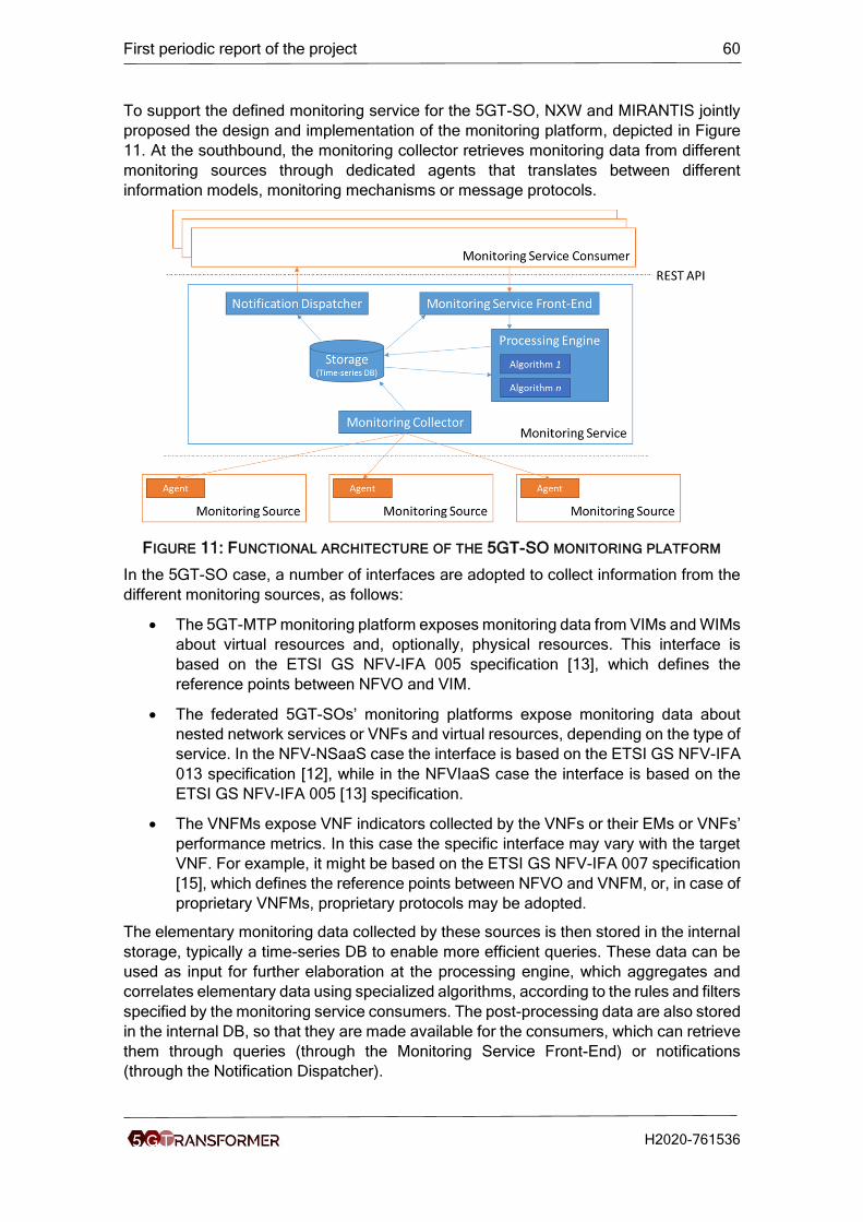
First periodic report of the project 60
H2020-761536
To support the defined monitoring service for the 5GT-SO, NXW and MIRANTIS jointly
proposed the design and implementation of the monitoring platform, depicted in Figure
11. At the southbound, the monitoring collector retrieves monitoring data from different
monitoring sources through dedicated agents that translates between different
information models, monitoring mechanisms or message protocols.
FIGURE 11: FUNCTIONAL ARCHITECTURE OF THE 5GT-SO MONITORING PLATFORM
In the 5GT-SO case, a number of interfaces are adopted to collect information from the
different monitoring sources, as follows:
• The 5GT-MTP monitoring platform exposes monitoring data from VIMs and WIMs
about virtual resources and, optionally, physical resources. This interface is
based on the ETSI GS NFV-IFA 005 specification [13], which defines the
reference points between NFVO and VIM.
• The federated 5GT-SOs’ monitoring platforms expose monitoring data about
nested network services or VNFs and virtual resources, depending on the type of
service. In the NFV-NSaaS case the interface is based on the ETSI GS NFV-IFA
013 specification [12], while in the NFVIaaS case the interface is based on the
ETSI GS NFV-IFA 005 [13] specification.
• The VNFMs expose VNF indicators collected by the VNFs or their EMs or VNFs’
performance metrics. In this case the specific interface may vary with the target
VNF. For example, it might be based on the ETSI GS NFV-IFA 007 specification
[15], which defines the reference points between NFVO and VNFM, or, in case of
proprietary VNFMs, proprietary protocols may be adopted.
The elementary monitoring data collected by these sources is then stored in the internal
storage, typically a time-series DB to enable more efficient queries. These data can be
used as input for further elaboration at the processing engine, which aggregates and
correlates elementary data using specialized algorithms, according to the rules and filters
specified by the monitoring service consumers. The post-processing data are also stored
in the internal DB, so that they are made available for the consumers, which can retrieve
them through queries (through the Monitoring Service Front-End) or notifications
(through the Notification Dispatcher).

First periodic report of the project 61
H2020-761536
The 5GT-SO Monitoring Service APIs should be compliant with the abstract messages
defined in the ETSI GS NFV-IFA 013 reference point [12], with particular reference to the
“NS Performance Management Interface” and the “NS Fault Management Interface”. The
Performance Management Interface provides messages for creating, deleting and
querying Performance Monitoring jobs (PMON jobs) as well as subscriptions and
notifications to receive monitoring reports. The Fault Management Interface provides
subscriptions, notifications and queries about alarms related to NFV network services’
and VNFs’ failures. Subscriptions and notifications can be also based on thresholds, in
order to receive events only when a specific condition occurs. This is particularly useful
to efficiently trigger NFV network service lifecycle commands, like scaling actions, to
automatically react in case of performance degradation or SLA violation. Moreover, the
ETSI GS NFV-IFA 013 [12] messages include several parameters to customize the
desired behaviour of the monitoring platform, for example in terms of filtering and
attributes selection in the queries, threshold specification, collection and reporting
periods for monitoring threads.
It should be noted that the 5GT-SO Monitoring Service APIs are also used in the
interaction between federated 5GT-SOs. In this case the APIs are used not only for
monitoring of NFV network services and VNFs (at the So-So-MON reference point), but
also for the monitoring of virtual resources provided by the peering administrative domain
(at the So-So-RMM reference point).
To support the implementation of the proposed monitoring platform, MIRANTIS has given
a detailed study of different OpenSource monitoring platforms and solutions. Based on
this study, MIRANTIS and NXW have proposed Prometheus 1 for monitoring and
Telegraf 2 for data collecting for the implementation of the 5G-TRANSFORMER
monitoring platform. To support the different partners to use the monitoring platform,
MIRANTIS has also provided a monitoring platform tutorial for the project. This tutorial
includes exporters, Prometheus, Alert Manager deployment and configuration.
4.2.4.3 Task 4.3: APIs and Service Federation
This task focuses on the design of federation mechanisms including the definition of the
federation procedures, workflows, interfaces and APIs, as well as federation algorithms
to provide end-to-end services and aggregate resources across multiple administration
domains.
UC3M leads this task with the support of the partners in T4.3 (NECLE, TID, ORANGE,
NXW, MIRANTIS, CTTC, EURECOM, SSSA, ITRI).
The main achievements of this task in the first period include:
• Definition of the federation mechanisms, related procedures and workflows;
• Design of the EBI/WBI towards federated service orchestrators;
• Starting the design of the federation algorithms.
Federation Mechanisms and EBI/WBI
Federation is a mechanism for integrating multiple administrative domains at different
granularity into a unified open platform where the federated resources and services can
trust each other at a certain degree. An administrative domain is a collection of network
services and resources operated by a single organization. The administrative domain is
1 https://prometheus.io/ 2 https://www.influxdata.com/time-series-platform/telegraf/

First periodic report of the project 62
H2020-761536
viewed as a single compact entity, where its internal structure is hidden or unimportant
from outside. The resources and services inside the administrative domain operate with
high degree of mutual trust among themselves, but the interaction with other
administrative domains is subject to stringent trustworthiness constraints, with a default
high level of alert. The federation is formed to increase the degree of trust among different
administrative domains with a goal of better interoperability of services and resources.
The embodiment of a service/business-level agreement or partnership between two
administrative domains is a federation of trust [19].
FIGURE 12: FEDERATION AS A DOMAIN UNIFIED BY MUTUAL TRUST [19]
In 5G-TRANSFORMER, the federation assumes already established business level and
service level agreements. It is assumed that the complete relationship between external
administrative domains is already defined. The federation levels are taken into account
and the scope is on the technical level. In the architecture of 5G-TRANSFORMER, all
federation procedures are executed on the 5GT-SO level using the EBI/WBI. More
precisely, all external connections are established by the 5GT-SO via EBI/WBI
(described in section 4.2.4.1).
We consider two types of federation:
• Service federation allows an administrative domain to request services that are
instantiated and managed by other peering administrative domains. Service
federation is corresponding to Network Service as a Service (NSaaS) for
federation of services.
• Resource federation allows an administrative domain to request, use, and
manage resources (including different types of resources, namely, networking,
storage and computing resources) that are owned by other peering administrative
domains. Resource federation is correspoding to NFVI as a Service (NFVIaaS)
for federation of resources.
The federation of services and federation of resources are two separate procedures that
take place in different phases of the service instantiation/modification within the 5GT-SO.
As shown in Figure 13, out of the six reference points composing on the EBI/WBI (as
described in section 4.2.4.1), two are used for service federation and three for resource
federation.

First periodic report of the project 63
H2020-761536
SO SO
So-So-LCM
So-So-MON
So-So-RM
So-So-RMM
So-So-RAM
SO NFVO-NSO
SO NFVO-NSO
SO NFVO-
RO
SO NFVO-
RO
So-So-CAT
SO-SOAdv
SO-SOAdv
FIGURE 13: 5GT-SO EBI/WBI REFERENCE POINTS
The details on the proposed federation procedures and the corresponding workflows
have been reported in D4.1 [5].
Federation Algorithms
In the first period of the project year, the design of the federation algorithms has started
with service/resource abstractions and specification of the high-level procedures that
should be handled by 5GT-SO’s algorithmic framework. This is work in progress, and the
development of the algorithms is planned for the second period of the project.
For the services, abstractions (i.e., lower level of details) are applied already during the
business negotiations. All information is hidden from a peering administrative domain.
Once the provider 5GT-SO NFVO-NSO enables a federation of NFV network service to
a consumer 5GT-SO, during the active phase it provides monitoring information with
abstracted parameters and indicators. These abstractions do not reveal the underlying
NFVI infrastructure, VNFs, PNFs, etc., that are enabling the federated NFV network
service. The level of revealed details on the information exchanged/exposed between
peering administrative domains depends on the agreed federation level according to the
business/level agreements.
For the federation of resources, the abstraction is applied twice. First, the 5G-MTP
applies resource abstraction on the underlying NFVI infrastructure. The abstraction
applied in the 5GT-MTP Resource Abstraction block is applied to hide some details of
NFVI resources from the local 5GT-SO. The second abstraction is applied upon
calculation of federation capabilities in the 5GT-SO NFVO-RO. The 5GT-SO NFVO-RO
reads information of available resources in the NFVI database (which are already
generated and stored abstractions from the 5GT-MTP) and performs calculation. The
outcomes of the calculations are categorized in federation levels. The categorized
information is sent to the SO-SO Advertisement block. This block broadcasts the
categorized resource abstractions to peering SOs according to the established
federation level.

First periodic report of the project 64
H2020-761536
Another case of federation is when the whole process is dynamically created. The
complete dynamical federation would consist of sharing service level agreements,
establishing connections, initiating federation services or resources, lifecycle of
federated services or resources. The realization of the dynamic approach can be
centralized or distributed as explained in D4.1 [5].
4.2.4.4 Deviations
Overall, the work package is proceeding as planned. There are changes for two partners
regarding the effort they plan to spend within WP4. MIRANTIS gave the leadership to
UC3M for the task T4.3, so as to focus the effort on the 5GT-SO implementation. Instead,
NXW is shifting 5PM from WP4 to WP3 to widen the scope of the 5GT-VS
implementation.
4.2.4.5 Corrective actions
No corrective actions needed.
4.2.5 WP5
The main objective of this work package is to integrate the 5G-TRANSFORMER platform
developed in WP2, WP3 and WP4 together with the different technologies available at
the four test-beds available in the project and the proof of concepts (PoCs) established
for the different use cases of the project. With this goal in mind, this WP is divided in
three tasks with different objectives: the definition and setup of the vertical testbeds
(T5.1), the integration of the platform and demonstration of the first PoCs (T5.2), and
finally a task fully advocated to experiment and evaluate the results (T5.3).
4.2.5.1 Task 5.1: Definition and set up of vertical testbeds
In T5.1 the main goal is to establish an initial planning for the integration between the
four different testbeds of the project, namely: ARNO (in Pisa, Italy), 5TONIC (in Madrid,
Spain), EURECOM (in Sophia Antipolis, France) and CTTC (in Barcelona, Spain), and
the PoCs associated to the different UCs from the different vertical industries that are
part of the project: Automotive, Entertainment, E-Health and E-Industry and also the
MNO/MVNOs UCs. To achieve this goal, the work has been taken following two different
directions. From one side the approach focused on describing the testbeds in terms of
technologies, establish an initial plan for the integration among them and setup the
physical connections that will support the integration. The other approach focused on
describing the PoCs associated with the different UCs and establish a mapping between
these PoCs and the technologies required from the testbeds and the functionalities
required from the 5G-TRANSFORMER platform.
The result from the testbed description, as established by ERICSSON, UC3M, NECLE,
SSSA, EURECOM and CTTC, is summarized in Figure 14, Figure 15, Figure 16, Figure
17, Figure 18 and Figure 19. For further details about the infrastructure of each testbed
we refer to D5.1 [6].

First periodic report of the project 65
H2020-761536
FIGURE 14: 5TONIC INFRASTRUCTURE (PARTNERS INVOLVED: UC3M, ERICSSON, NECLE)
FIGURE 15: CTTC TESTBED INFRASTRUCTURE (PARTNERS INVOLVED: CTTC)

First periodic report of the project 66
H2020-761536
FIGURE 16: EURECOM INFRASTRUCTURE (PARTNERS INVOLVED: EURECOM)
FIGURE 17: EURECOM MEC PLATFORM (PARTNERS INVOLVED: EURECOM)

First periodic report of the project 67
H2020-761536
FIGURE 18: ARNO ACCESS (PARTNERS INVOLVED: SSSA)
FIGURE 19: ARNO INFRASTRUCTURE (PARTNERS INVOLVED: SSSA)
In terms of technologies we obtained the set of technologies available in the integrated
testbed as shown in Table 9 (please refer to D5.1 [6] for the technology identifiers). The
first phase contains the technologies already available in the testbeds since M1, while
the second phase show the ones planned to be included after M18.
TABLE 9: INTEGRATED TESTBED TECHNOLOGIES (UC3M, SSSA, ERICSSON, NECLE, EURECOM AND CTTC)
ID First phase (M1) Second phase (M18)
Heterogeneous
T1.a USRP cards and OAI software, LTE-A microcells, virtualized EPC, mmWave base stations for fronthaul and backhaul traffic, user equipment for LTE-A. Spectrum licenses: 1.8(FDD-LTE), 2.6 (FDD-LTE), 3.5 (TDD-LTE), 2.4 and 5.2 (Wifi). Channel Bandwidth: 5MHz, 10MHz, and 20 MHz (FDD-LTE). C-RAN with Option 8 and Option7-1 functional splits support. Emulated IoT environment (InstantContiki). XGS-PON.
C-RAN (radio access with different functional splits), massive MIMO. Wireless transmission in unlicensed bands.

First periodic report of the project 68
H2020-761536
Targeted Virtual Networks (VNF)
T2.a OpenStack with different tenants. Not guaranteeing SLAs yet. RAN and EPC slice creation and instantiation using a customised version of OAI and a Slice Orchestrator. OpenFlow controllers (NOX/Floodlight/ODL/ONOS) OpenStack controller and XCP Virtual Machine Manager SONA framework for SDN-based OpenStack networking Orchestrators for cloud DCs and edge SDN networks. Reconfiguration/Orchestration in SDN network domains.
Integration with MANO. Plan to include joint orchestration across SDN and Cloud domains.
T2.b VNFs implementing routers, firewalls, EPC and part of eNodeB. Service Function Chaining. NS-3 LENA modules (access and core) for mobile network emulation. A programmable RAN based on FlexRAN protocol (OAI-based). A SDN-based EPC architecture (split of S/P-GW: S/P-GW-C and S/P-GW-U). Virtualized DU, CU, and EPC via Virtualbox, KVM, Docker container.
VNFs implementing the different components of an EPC.
T2.c ETSI OpenSourceMANO v2 as MANO controlling several OpenStack as the VIMs. Different SDN controllers (e.g., Ryu, ONOS, etc.) based on different implementations and relying on separated APIs (OFP, NETCONF/YANG) for heterogeneous switching capabilities and technologies. Shell-based flexible functional split (Option 8 to Option 7a) Reconfiguration/Orchestration in a single domain. Multidomain resource advertisement based on BGP-LS.
ETSI OpenSourceMANO v3 or beyond. Federation of testbeds. Interconnection (at some extent) of (two) Service Orchestrators. Flexible functional split (Option 8 to Option 7a) Reconfiguration/Orchestration based on Kubernetes in a single domain.
T2.f End-to-end performance measurements for LTE and C-RAN (including core) with OAI
Cloud and Edge computing functions (CLD)
T3.b MEC platform based on OAI. It implements mp1 (REST) and mp2 (FlexRAN and OpenFlow) interfaces. It provides the following MEC services: Traffic redirection, RNIS (a part), Service Registry and Service Discovery.
Enrich the RNIS API and integrate with a NFV MANO.
OpenVPN to access the laboratory. ARNO testbed federated in Fed4FIRE through jFed where users can access LTE/C-RAN components.
Enhanced privacy and Security Techniques (PRIV)

First periodic report of the project 69
H2020-761536
T4.a OpenVPN to access the laboratory. ARNO testbed federated in Fed4FIRE through jFed where users can access LTE/C-RAN components.
Broadcast and Streaming Functions (eMBB)
T5.b VNF SIP proxies
IoT Enabler Functions (mMTC)
T6.a WiFi Direct devices.
From the testbed integration perspective, in T5.1 we have also been working on an
integration map that would enable us to demonstrate all the features from the project
related to the physical infrastructure. In Figure 20 we show the initial testbed integration
map. We have purposely omitted the names of the testbeds in this diagram, since this
exact mapping is subject of further discussion as described at the end of this section.
FIGURE 20: TESTBED INTEGRATION PLAN (UC3M, SSSA, ERICSSON, NECLE, EURECOM)
The second approach focused on understanding the expectations from the vertical
industries, represented by: CRF, ATOS, SAMUR, TEI (with the support of NOK-N and
UC3M) and the MNO/MVNOs represented by BCOM and ITRI. The outcome of this
analysis is summarized in Table 10 as a set of functional requirements for the 5G-
TRANSFORMER (also described in D5.1 [6]).
TABLE 10: 5G-TRANSFORMER FUNCTIONAL REQUIREMENTS (ATOS, UC3M, CRF, BCOM, NOK-N, SAMUR, TEI)
Id Name Description Architectural components involved
FR1. Federation Seamlessly deploy a vertical
service using resources or
network services belonging to
different administrative
domains.
5GT-SO

First periodic report of the project 70
H2020-761536
FR2. Vertical Service
Composition.
Instantiate vertical services
that use the instances of other
vertical services.
5GT-VS
FR3. Lifecycle
management of
vertical service.
Control the lifecycle of the
vertical service.
5GT-VS
FR4. Dynamic
Changes of
vertical service.
Give the VNFs/VAs composing
the vertical service the
possibility of scaling up/down
the resources assigned to the
service based on internal
triggers.
5GT-VS
FR5. Arbitration. Automatic mechanism to act
on resource outage based on
vertical service priorities, etc.
5GT-VS
FR6. Vertical service
distribution
across multiple
Data Centers.
Integrate the resources and
network services instantiated
over multiple data centers.
5GT-MTP
FR7. Lifecycle
management of
network slices.
Give the verticals the
possibility of controlling the
network slices associated to
their vertical services.
5GT-VS
FR8. SLA definition. Define and enforce service
level agreements.
5GT-VS, 5GT-SO
FR9. Monitoring Provide the verticals the
capability of monitoring all the
monitoring items associated to
the vertical service.
5GT-VS, 5GT-SO, 5GT-MTP
FR10. Orchestration-
Placement
Provide the verticals the
possibility of defining rules or
algorithms that could influence
the placement decisions.
5GT-VS, 5GT-SO
FR11. Orchestration-
Scaling
Provide the verticals the
possibility of defining rules or
algorithms that could influence
the scaling decisions.
5GT-VS, 5GT-SO
FR12. MEC Integration Seamlessly integrate the MEC
platform.
5GT-VS, 5GT-SO, 5GT-MTP
These functional requirements are aligned with the contributions of the project and
identify which are the features that the partners are most willing to demonstrate. This set
was also used in WP2, WP3 and WP4 to establish a release roadmap for the platform.

First periodic report of the project 71
H2020-761536
Finally, in T5.1 we used the UCs selected for demonstration (which are reported in D1.2
[2]), and described them in D5.1 [6] as a set of PoCs which are mapped to the
technologies and functional requirements from Table 9 and Table 10. Table 11
summarizes the PoCs established in D5.1 by CRF, POLITO, NXW, Atos, SAMUR,
UC3M, TEI, BCOM and ITRI.
TABLE 11: 5G-TRANSFORMER POCS
PoC id Description Functionalities to be tested
Required technologies
Verification
Automotive (CRF, POLITO, NXW)
1.1 The vehicle exchanges messages (CAM, DeNM) with a road-site unit (RSU) deployed on MEC host. A Video streaming service is deployed in the MEC host and delivered to the vehicle UE.
Slice creation and instantiation in MEC host, Data and control connectivity between vehicle and infrastructure. (FR2, FR12)
T1.a, T5.b Required Traffic flows from the vehicle to the RSU.
1.2 CIM (in the MEC host) receives and processes messages from the vehicle and the traffic simulator
Slice creation and third party Application Server Instantiation
T3.b,T2.h, T2.c, T2.d
Required traffic flows between the MEC and all involved entities (including traffic simulator input to CIM).
1.2 plus
Integration of real radio equipment
Data plane connectivity among radio transport and cloud
T1.a, T1.d, T3.b,T2.h, T2.c, T2.d
Required E2E latency (radio protocol contribution between modem and SGi interface, transport contribution, SGi interface and MEC processing time of algorithm
1.3 The Extended-Sensing in the MEC host processes context data from CIM and compute decision (special message) to be notified to the vehicle.
Car Maker Application Server Instantiation and configuration in the car maker slice
T2.b, T2.d, T2.f, T3.b
Communication between VAs in MEC host Required latency and impact of Extended-Sensing algorithm
1.4 In vehicles Integration + Backends (optional)
Cloud functionalities
T3.a, T2.i, T2.b, T2.d
End to End communication among all the service components
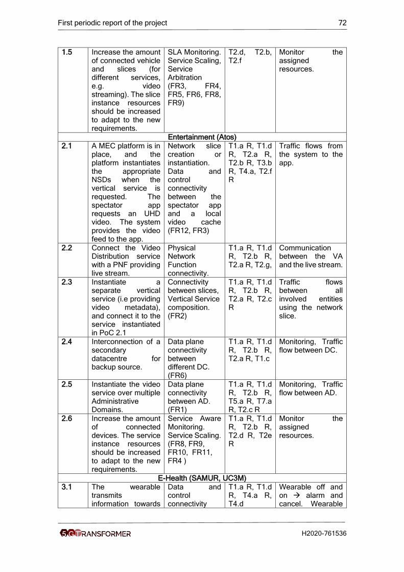
First periodic report of the project 72
H2020-761536
1.5 Increase the amount of connected vehicle and slices (for different services, e.g. video streaming). The slice instance resources should be increased to adapt to the new requirements.
SLA Monitoring. Service Scaling, Service Arbitration (FR3, FR4, FR5, FR6, FR8, FR9)
T2.d, T2.b, T2.f
Monitor the assigned resources.
Entertainment (Atos)
2.1 A MEC platform is in place, and the platform instantiates the appropriate NSDs when the vertical service is requested. The spectator app requests an UHD video. The system provides the video feed to the app.
Network slice creation or instantiation. Data and control connectivity between the spectator app and a local video cache (FR12, FR3)
T1.a R, T1.d R, T2.a R, T2.b R, T3.b R, T4.a, T2.f R
Traffic flows from the system to the app.
2.2 Connect the Video Distribution service with a PNF providing live stream.
Physical Network Function connectivity.
T1.a R, T1.d R, T2.b R, T2.a R, T2.g,
Communication between the VA and the live stream.
2.3 Instantiate a separate vertical service (i.e providing video metadata), and connect it to the service instantiated in PoC 2.1
Connectivity between slices, Vertical Service composition. (FR2)
T1.a R, T1.d R, T2.b R, T2.a R, T2.c R
Traffic flows between all involved entities using the network slice.
2.4 Interconnection of a secondary datacentre for backup source.
Data plane connectivity between different DC. (FR6)
T1.a R, T1.d R, T2.b R, T2.a R, T1.c
Monitoring, Traffic flow between DC.
2.5 Instantiate the video service over multiple Administrative Domains.
Data plane connectivity between AD. (FR1)
T1.a R, T1.d R, T2.b R, T5.a R, T7.a R, T2.c R
Monitoring, Traffic flow between AD.
2.6 Increase the amount of connected devices. The service instance resources should be increased to adapt to the new requirements.
Service Aware Monitoring. Service Scaling. (FR8, FR9, FR10, FR11, FR4 )
T1.a R, T1.d R, T2.b R, T2.d R, T2e R
Monitor the assigned resources.
E-Health (SAMUR, UC3M)
3.1 The wearable transmits information towards
Data and control connectivity
T1.a R, T1.d R, T4.a R, T4.d
Wearable off and on → alarm and cancel. Wearable

First periodic report of the project 73
H2020-761536
the eServer, which analyse the information. When an issue is detected, the eServer contacts the wearable to confirm or discards the alert.
between the wearable and the eServer, data analysis, alert confirmations. (FR1, FR3, FR6, FR10)
off → alarm and confirmation.
3.2 A MEC platform is deployed over the instantiated network slice.
MEC functionalities (FR8, FR12)
T3.b R Required traffic flows between the MEC and all involved entities.
3.3 After an alarm is confirmed, the wearable starts searching for paramedics in the neighbour area. If any paramedic is found, a communication is established.
Device-to-device communication.
T6.a R Communication between patient and paramedic devices is established.
3.4 After an alarm is confirmed, the eServer requests the configuration of a network slice among all involved entities is instantiated.
Network slice creation or instantiation. (FR4, FR5, FR9, FR11)
T2.a D, T2.b R, T2.c R, T5.b D, T7.a D.
Traffic flows between all involved entities using the network slice.
E-Industry (TEI)
4.1 Preparatory experiment for cloud robotics (CR) service activation.
Traffic isolation. (FR8)
T2.a R, T2.b R
Verify the latency requirements and service isolation. This test will enable the network slice creation and instantiation in a next step.
4.2 CR service activation
Data plane connectivity among Radio Transport and Cloud (FR3, FR7, FR6)
T1.a R, T1.d R, T4.a R, T6.b R
Check if latency requirements are met in different virtualization scenario and different (v)EPC location.
4.3 Monitoring of failures on the transport domain
Monitoring of the transport domain for enabling recovery of degraded connectivity (FR9)
5G-MTP perform the monitoring for enabling recovery.
MNO/MVNO (BCOM, ITRI)

First periodic report of the project 74
H2020-761536
5.1 MNO requests the instantiation of a specific 5G network with local access to the infrastructure, in a split vEPC mode
Network slice template provision (SLA) (FR8)
T2.a R, Vertical slicer order sent to 5GT-SO for network service instance creation
5.2 End to end network slice set up and vEPC network service are instantiated, connected to local small cells and Wi-Fi APs.
Network slice/service instantiation. Multi-access CP/UP split. Access to local and central cloud. Interconnection with legacy MNO services (HSS at least) (FR1, FR2, FR3)
T1.a R, T1.d R, T2.a R, T2.b R, T2.f R, T2.c R.
VNFs are up and running
5.3 End-users are provided with multi connectivity (4G/5G/Wi-Fi), homogeneous QoE and unified authentication
Multi access, unified authentication
T2.b R, T4.a R, T2.f D
UE connectivity via Cellular access and WiFi access towards Internet
5.4 Direct access to local cloud allows end users to share and store their data locally with low delay and high bandwidth;
Local servers, applications (cache, CDN) (FR6, FR7)
T3.a R, T5.a D.
UE retrieve content cached in local Data Center
5.5 Monitoring allows troubleshooting operations
Virtualized monitoring (FR9)
Traffic probe instantiated, monitoring dashboard
The remaining effort in T5.1 will focus on further detailing the integration map between
the testbeds, the PoCs and the functionalities from the platform. This discussion will
involve all the testbed representatives and the partners contributing with the
implementation of the UCs, and will consider: the PoCs established for the UCs, the
result of the performance tests and the feasibility for the testbeds to embrace the different
components of the architecture.
4.2.5.2 Task 5.2: Integration and proof of concept
In T5.2, which started on M8, we first focused on establishing an integration plan which
considers the PoCs (from Table 11) and the releases of the platform. The outcome of
this is shown in Figure 21.

First periodic report of the project 75
H2020-761536
FIGURE 21: POC SCHEDULING
With this schedule in mind, and using the release map from WP2, WP3 and WP4 we
planned three demonstrations exhibited at the EuCNC 2018.
The first demonstration, involving NXW, ATOS and UC3M, aimed to show a prototype of
the 5GT-VS running on top of the NFVO used in the 5G-Crosshaul project, to deploy the
key components of the Entertainment UC of the project. The objective is to demonstrate
how the 5GT-VS can translate the parameters of the vertical service into different network
service descriptors. Particularly, the demo will show how the number of users can be
used as a parameter to instantiate services with different amount of resources. In this
case the number of users is used to determine the number of video caches in the edge
of the network.
The second demonstration, presented by IDCC and EURECOM, at the EUCNC will show
the application cases for the Radio Network Information Service (RNIS) with a focus on
cloud robotics. We are demonstrating an LTE network where a robot equipped with an

First periodic report of the project 76
H2020-761536
LTE interface is attached to an OpenAirInterface eNodeB and EPC. The RNIS is exposed
and applications can consume it over a REST API to retrieve, among others, run-time
Channel Quality Indications (CQI) per UE. The RNIS collects this information from agents
built into eNodeBs using the FlexRAN southbound protocol. The purpose of this
demonstration is to show how applications can make the best of the RAN-level
awareness offered by the RNIS for real-time adaptations, particularly focusing on cloud
robotics scenarios.
Finally, the third demonstration, by MIRANTIS, ATOS and UC3M, used Cloudify (i.e. the
platform chosen as reference for the 5GT-SO in WP4) to orchestrate the key components
of the Entertainment use case using private and public clouds (5tonic and Amazon AWS
respectively). The main goal is to demonstrate a custom plugin developed for Cloudify
which can automatically provision the VPN endpoints and create the tunnels to connect
different network clouds, and how a vCDN service can be built on top of this.
The next steps in T5.2 will focused on the development of the PoCs of the UC, and use
the output generated by the integration map in T5.1 to advocate the effort to prepare the
testbeds.
4.2.5.3 Task 5.3: Experimentation and evaluation
T5.3 started in M10 and aims to further detail how the different PoCs will demonstrate
the KPIs established for the project. We refer to section 4.6.1 for details about the KPIs
of the project and how these are mapped to the ones identified by the 5GPPP. The effort
in this task, by ATOS, UC3M, SAMUR, TEI, CRF, ITRI, BCOM and SSSA, has been set
on identifying which KPIs are most relevant for each UC (and the correspondent values)
and setting a common methodology to collect the quantitative and qualitative information.
Since this task is inherently related to the monitoring platform, we have been working in
tight collaboration with the rest of the WPs to ensure a full support from the platform to
collect the required information.
The demos at the EUCNC18 by ATOS, MIRANTIS and NXW, detailed in the previous
section, already produced in terms KPIs: namely the service instantiation time, end to
end latency and data rate (LAT, UDR and SER from Table 19). Once we finish with the
process of mapping the KPIs to the UCs and establishing the methodology, we will focus
on analysing if it is feasible to demonstrate KPIs not originally considered in the project.
4.2.5.4 Deviations
In September 2017, Juan Brenes replaced José Enrique González as WP5 leader (both
from ATOS).
4.2.5.5 Corrective actions
No corrective actions needed.
4.2.6 WP6
As far as this project is concerned, and in accordance with common practice at the EU
level [1],[8],Communication includes all the activities related with the promotion of the
project and its results beyond the projects own community. This includes the interaction
with other research projects (e.g., H2020 5G PPP) as well as communication of its
research in a way that is understood by the non-specialist, e.g. the media and the public.
Notice, though, that even if collaboration with other projects is presented under
communication, it also spans dissemination and exploitation. Dissemination includes
activities related with raising awareness of its results in a technical community working
First periodic report of the project 77
H2020-761536
on the same research field. In general, this will be done through publications, and
participation and organization of technical events. Finally, exploitation (in accordance
with the European IPR Helpdesk) covers activities aiming at using the results in further
research activities other than those covered by the project, or in developing, creating and
marketing a products or processes, or in creating and providing a service, or in
standardization activities.
Though a brief global overview is provided in the following paragraphs, the detailed work
carried out in WP6 is reflected in various sections throughout this document according to
the template. Communication activities (i.e., the outcome of task 6.1) are presented in
this section, Dissemination activities (i.e., the outcome of task 6.2) are presented in
section 3, and Exploitation activities (including standardization) are presented in section
4.5, and are also as an outcome of task 6.2. Finally, section 5 refers to D6.2 [22] (just
released) for an updated communication, dissemination, and exploitation plan (CoDEP)
of 5G-TRANSFORMER.
In accordance with the communication, dissemination, and exploitation plan (CoDEP)
presented in the DoA (see FIGURE 22), the first period of the project is mainly devoted to
raise awareness about the scope and approach of 5G-TRANSFORMER. This phase
starts with the preparation of communication material as well as the website and social
media and ends with the demonstrations carried out at EUCNC’18 in the 5G-
TRANSFORMER booth (which was prepared in cooperation with 5GEx and 5G-CORAL
projects).
Therefore, task 6.1 has a starring role in this respect. In this direction, various project
partners presented the project in various events, participated in coordination calls with
other 5G-PPP projects and prepared the website and social media of the project. This
allowed achieving the milestone set for M3 (August 2017), which also included the
preparation of communication material, such as the leaflet and poster (and also a
reference communication presentation). Since the project started, there has been a
steady increase of the web and social media impact, for instance, reaching 4000 visits
on the web or 32000 Twitter impressions.
Communication actions for society at large were also carried out. Various events were
also co-organised by 5G-TRANSFORMER with other H2020 projects (most of them 5G-
PPP ones). More specifically, the joint work with other 5G-PPP projects was carried out
in various forms. Events organized during 2017 are: The O4SDI workshop, the 5G and
automotive workshop, or one WWRF39 session. A workshop co-located with IEEE
WCNC’18 (1st COMPASS) was also submitted, accepted and already took place on April
2018. A workshop co-located with IEEE BMSB’18 was also accepted (2nd COMPASS)
as well as one at EUCNC’18 jointly with other 5G-PPP projects (Multi-provider, multi-
vendor, multi-player orchestration: from distributed cloud to edge and fog environments
in 5G). Additionally, 5G-TRANSFORMER also participates in the workshop organized at
EUCNC’18 by the 5G-PPP Software Networks working group (From cloud ready to cloud
native transformation: What it means and Why it matters). Finally, a PIMRC’18 workshop
jointly organized with 5G-AURA was also accepted.
In addition to jointly organized events, the project is regularly participating in 5G-PPP
working groups, and preparing joint papers. The project also regularly participates in 5G-
PPP COMMS group, an activity organized by the To-Euro-5G CSA towards a joint
dissemination strategy of all 5G-PPP projects, and so, regularly exploits these joint
channels.

First periodic report of the project 78
H2020-761536
Several talks (technical and general public), publications, student supervision, etc. were
also given during this period.
As for dissemination and exploitation (task 6.2), several actions were also carried out. A
number of papers (6 in Journals, 20 at conferences and 9 at workshops) were accepted
and presented in international journals and conferences (e.g., IEEE Transactions on
Mobile Computing, EUCNC, IEEE INFOCOM).
Furthermore, the participation of the project at the Mobile World Congress (MWC) held
in Barcelona (26 Feb-1 Mar) is also relevant in this respect. Additionally, four
demonstrations were presented at EUCNC, in a joint booth with 5G-Ex and 5G-CORAL,
and one at IEEE INFOCOM 2018. A demonstration to the PSA group was also performed
at 5TONIC premises.
Moreover, the first months were also devoted to refining the CoDEP originally presented
in the proposal, with especial emphasis on the exploitation plan (incl. standardisation). A
number of results in terms of standardisation were also achieved, since the ETSI MEC
group approved the creation of a work item on “Slicing and Federation across distributed
MEC platforms”, which was promoted by 5G-TRANSFORMER partners. Other
standardization results were also obtained, from creation of new work items to publication
of IETF drafts, to contributions to 3GPP. A standardization advisory committee (SAC)
was specifically created to coordinate the work, continuously refine the roadmap and
maximize impact. As part of these roadmap, a number of contributions, mostly to ETSI
MEC and IETF working groups (e.g., NFVRG, CCAMP) were submitted. 16 contributions
to four different SDOs: 10 to IETF, 1 to 3GPP, 4 to ETSI MEC, and 1 to NGMN.
Finally, let us also highlight that the project was granted all five services requested for
the Common Dissemination Booster, jointly with other projects (5G-Crosshaul and 5G-
Coral), which started its operation in May 2018.

First periodic report of the project 79
H2020-761536
FIGURE 22: 5G-TRANSFORMER COMMUNICATION, DISSEMINATION, AND
EXPLOITATION PLAN (CODEP)
As mentioned above, the following subsection focuses on communication activities since
dissemination and exploitation ones have their own one.
4.2.6.1 Communication activities
This section reports on the communication activities undertaken related to the society at
large and the events fostering interaction with other projects. Each subsection describes
different activities and events for the promotion of the 5G-TRANSFORMER project. All
5G-TRANSFORMER partners promote the 5G-TRANSFORMER project to the general
public at large, and many activities (e.g., social media and video post, press releases
and news release, communication articles published, etc.) were carried out, as seen in
the following subsections.

First periodic report of the project 80
H2020-761536
4.2.6.1.1 Web, social media, and project communication material
Following the project kick-off on June 1, 2017 in Stockholm, activities have been
undertaken towards fulfilling the objectives set above. Additionally, the official project
press release was released in Madrid, Spain in June 2017. Additionally, partners also
released their own internal (company-wide) and external press releases as listed in
Section 4.2.6.1.4. More details can also be found in the project website (http://5g-
transformer.eu/).
The social media accounts of 5G-TRANSFORMER were also set up, and are the
following:
• Twitter: https://twitter.com/5g_transformer
• LinkedIn: http://linkedin.com/in/5g-transformer-eu-project-a05311144
• Instagram: https://www.instagram.com/5g_transformer/
• YouTube: https://www.youtube.com/channel/UClQXD0lCxTK9eh_mQzMweww
By looking at the metrics, one can conclude that there has been a steady increase of the
impact of the website and of social media, which is a relevant outcome as part of the
CoDEP execution during the raise awareness phase of the project. More specifically, for
the website, we have observed around 4000 visits and 1800 visitors in the last quarters
with the most visited page reaching more than 1000 visits (/publications). As for Twitter,
the number of followers reached 275. The number of impressions (i.e., times a user is
served a Tweet in timeline or search results) moved from thousands during the initial
months of the project to 10s of thousands in recent quarters (up to a max. of almost
33000). The same trend as in Twitter is observed in the rest of social media (Instagram,
LinkedIn and YouTube), though with a lower intensity. For instance, in Instagram, as of
April 2018, the project has 19 followers and 172 LinkedIn followers. Furthermore, the 5G-
TRANSFORMER high-level video had more than 500 visualizations since February 2018
(in addition to those during the events in which it was played, such a Mobile World
Congress). More technical videos will be recorded and published on the YouTube
channel for some of the demonstrations of the project (e.g., EUCNC).
4.2.6.1.2 Communication leaflets and poster
Various communication leaflets and posters were produced. They were used in various
events and available on the web for the promotion of the 5G-TRANSFORMER project. A
specific version was generated to be used in the 5G-Infrastructure Association booth and
booths from partners during Mobile World Congress 2018. Figure 23 presents an
example of leaflet prepared for Mobile World Congress 2018.

First periodic report of the project 81
H2020-761536
FIGURE 23: MOBILE WORLD CONGRESS 2018 5G-TRANSFORMER LEAFLET
4.2.6.1.3 Communication videos
The 5G-TRANSFORMER general video was published on the 19 February, 2018. This
video introduces the use cases considered in the 5G-TRANSFORMER project: eHealth,
Automotive, M(V)NO, Media, Cloud robotics. It also explains how 5G-TRANSFORMER
can enable vertical industries to meet their service requirements within customized 5GT-
MTP slices and how it can also enable the federation among transport networking and
computing fabric from the edge up to core and cloud belonging to different domains. Also,

First periodic report of the project 82
H2020-761536
this video was shown in Mobile World Congress in Barcelona, Spain, 2018 in the 5G-
Infrastructure Association booth as well as in the booth of partners.
Additionally, this video was registered to participate in the “Showcase your project!”
initiative (http://ec.europa.eu/research/investeuresearch/index.cfm), which builds a
library of videos explaining how European research impacts the daily lives of citizen. It is
available at: https://www.youtube.com/playlist?list=PLvpwIjZTs-
LjHDvRTqlyjfLeflXDak5er
An interview to Prof. Arturo Azcorra, deputy coordinator of 5G-TRANSFORMER,
recorded at EuCNC 2018 has also been published.
4.2.6.1.3.1 Demo videos
As part of the technology demonstrations efforts, videos are expected to be recorded
throughout the project lifetime and made available through our website. These videos
will present the goals and scenario of the demo and explain in detail all the steps followed.
They also show the final result after the 5G-TRANSFORMER service is deployed.
As of the time of writing, videos of the EuCNC 2018 demonstrations (see Table 2) were
recorded and have been uploaded to the video gallery of the 5G-TRANSFORMER
website (http://5g-transformer.eu/index.php/dissemination/video-gallery/).
4.2.6.1.4 Press releases and news
A list of the press releases on 5G-TRANSFORMER project that appear in 5G-
TRANSFORMER website. Two official project-wide press releases were published, for
the kick-off and for Mobile World Congress 2018:
• http://5g-transformer.eu/index.php/2017/06/20/5g-transformer-press-release/
• http://5g-transformer.eu/index.php/2018/02/23/the-5g-transformer-project-
presents-the-future-5g-mobile-transport-platform-for-verticals-at-mwc18/
Furthermore, the project regularly publishes news on relevant events and results. For
instance, one was published on the participation to the Common Dissemination Booster
and two on the presence at EUCNC 2018, among others:
• http://5g-transformer.eu/index.php/2018/06/21/5g-transformer-presence-at-
eucnc-2018-ljubljana-slovenia/
• http://5g-transformer.eu/index.php/2018/06/22/the-european-commission-
representatives-visited-the-5g-coral-5g-transformer-and-5g-ex-joint-booth-at-
eucnc-2018/
• http://5g-transformer.eu/index.php/2018/06/05/5g_in_cbd/
Additionally, several press releases were also issued by various partners at various
stages of the project, which were promoted through their respective communication
channels (including their website):
• https://www.mirantis.com/blog/network-slicing-and-5g-and-wireless-oh-my/
• http://www.cttc.cat/european-industrial-and-academic-partners-join-to-develop-
a-5g-mobile-transport-platform-for-verticals/
• https://www.ericsson.com/research-blog/5g-transformer-eu-project-underway/
• https://www.networks.imdea.org/whats-new/news/2018/investigadores-uc3m-
presentan-sus-novedades-sobre-5g-mobile-world-congress-2018
• http://www.cttc.cat/cttc-contributes-to-the-future-5g-mobile-transport-platform-
for-verticals-at-mwc18/

First periodic report of the project 83
H2020-761536
• http://5g-xcast.eu/2018/04/26/prof-narcis-cardona-presentation-at-the-5g-forum-
in-malaga/
• http://www.madrid.es/portales/munimadrid/es/Inicio/Emergencias-y-
seguridad/SAMUR-Proteccion-
Civil/?vgnextfmt=default&vgnextoid=c88fcdb1bfffa010VgnVCM100000d90ca8c
0RCRD&vgnextchannel=f9cd31d3b28fe410VgnVCM1000000b205a0aRCRD&i
dCapitulo=6149819
• http://s3platform.jrc.ec.europa.eu/digital-innovation-hubs-
tool?p_p_id=%20digitalinnovationhub_WAR_digitalinnovationhubportlet&p_p_lif
ecycle=0&p_%20p_state=normal&p_p_mode=view&p_p_col_id=column-
%201&p_p_col_count=1&formDate=1524592222123&freeSearch=5tonic&evol
Stages=3
• http://5g-transformer.eu/index.php/2018/04/20/5g-transformer-in-collaboration-
with-samur-proteccion-civil/
But most notably, the project also had some presence in relevant technical
communication media, such as sdxcentral or globenewswire:
• http://www.globenewswire.com/news-
release/2017/06/21/1027019/0/en/European-Industrial-and-Academic-Partners-
Join-to-Develop-a-5G-Mobile-Transport-Platform-for-Verticals.html
• https://www.sdxcentral.com/articles/news/new-european-5g-group-will-focus-
on-network-slicing-industry-verticals/2017/06/
• https://www-sdxcentral-
com.cdn.ampproject.org/c/s/www.sdxcentral.com/%20articles/news/trials-use-
cases-top-5g-developments-
2017/2017/12/amp/%20Network%20Slicing%20Gets%20Traction
The channels available through the 5G-PPP COMMS group, coordinated by the To-Euro-
5G CSA were also exploited throughout the first year of the project. This is a group
established at the 5G-PPP projects level to raise awareness of the activities of these
projects among them and also outside, through various media (e.g., newsflash, social
media, periodic audioconferences). For instance:
• https://5g-ppp.eu/european-industrial-and-academic-partners-join-to-develop-a-
5g-mobile-transport-platform-for-verticals/
• https://5g-ppp.eu/newsflash-october-2017/
• https://5g-ppp.eu/the-5g-transformer-project-presents-the-future-5g-mobile-
transport-platform-for-verticals-mwc18/
4.2.6.1.5 Communication articles
In addition to publishing technical papers, the project also promotes the project scope
and vision at a higher-level. Table 12 lists the communication articles published to
introduce the 5G-TRANSFORMER project from the point of views of a mobile network
operator and verticals.

First periodic report of the project 84
H2020-761536
TABLE 12: COMMUNICATION ARTICLES
Title Venue 1 A Network Service Provider
Perspective on Network Slicing IEEE Softwarization, January 2018
2 5G-TRANSFORMER (5G Mobile Transport Platform for Verticals) (sent)
5G Annual Journal Third Edition
4.2.6.1.6 Communication presentation/lectures
Table 13 lists the presentations and talks targeting a wide general audience. This
includes high-school students or society at large. It also includes lectures given to
undergraduate and graduate students, as part of this general, but a bit more technical
audience. And finally, it also includes general talks given at more technical for a but not
necessarily specifically working on the same topics as 5G-TRANSFORMER (e.g., 5G
Summit) as part of the interaction with other projects. They all describe the project
general ideas and scope without entering too much into technical details.
TABLE 13: COMMUNICATION PRESENTATION AND LECTURES
Activity
1 Talk entitled “5G Networks to realize Network society“ at the “5G technology for automotive domain” workshop, 2017, including the 5G-TRANSFORMER approach.
2 A talk on 5G in general, and more specifically, on 5G-TRANSFORMER was given to high-school students and general public in the context of 22nd Open
Science Week (Setmana de le Ciència) in November 2017. It is organized by
the Catalan Research and Innovation Foundation (FCRi). Information available at: http://www.cttc.cat/the-cttc-will-participate-in-the-22nd-edition-of-the-science-week-2017/
3 Organization of the Internet Festival (http://www.internetfestival.it/), the Robotics Festival 2017 (http://www.festivalinternazionaledellarobotica.it/en/)
4 Three-hour course taught at the National Chiao Tung University (NCTU) in Taiwan on topics related with 5G-TRANSFORMER
5 Master courses in UC3M on NFV and SDN for 5G networks
6 SSSA presents 5G-TRANSFORMER in 5G Summit in Trento
7 5G-TRANSFORMER presentation: 5G Mobile Transport Platform for Verticals in EuCNC workshop in 2017
8 POLITO presents 5G-TRANSFORMER in IEEE 5G Summit 2017 talk
9 SAMUR participation and presentation in 5G Forum in Malaga
4.2.6.1.7 Collaboration with other projects
A series of activities have been carried out together with 5G-PPP projects in the
framework of the various working groups. Table 14 lists the main activities within the 5G
PPP CSA Working Groups (WGs). A variety of other activities, like joint organization of
events or special sessions, joint booth applications at events, or joint writing of papers
were carried out. They will be explained in the corresponding sections below. This
section focuses on the 5G-PPP working group activities.
TABLE 14: ACTIVITY WITHIN 5G PPP CSA WGS
Activity with 5G PPP WGs
1 Presentation to EC H2020 5G Infrastructure PPP Technical board on Performance KPIs and 5G-TRANSFORMER status in this respect. Active participation on this activity (periodic calls).

First periodic report of the project 85
H2020-761536
2 Inputs on 3GPP and 5G-TRANSFORMER to 5G-PPP Pre-Standardization Working Group (WG). Various conference calls, including one with the WG Chair on including other non-3GPP activities.
3 Input on 5G-TRANSFORMER for preparation of a brochure for EUCNC. 5G PPP Network Management & QoS WG
4 Participation to 5G PPP Trials WG and the roadmap (5G Pan-European trials roadmap 3.0.) generated by the group (https://5g-ppp.eu/5g-trials-roadmap/ ).
5 Participation to 5G PPP Architecture WG. The group organized a session at EuCNC 2018.
6 Active participation to the 5G PPP Software Networks WG. The 5G-TRANSFORMER project was presented in September 2017. 5G-TRANSFORMER contributed actively to the white paper ‘From Webscale to Telco, the Cloud Native Journey’’. The white paper will be presented at a EUCNC 2018 workshop, to which 5G-TRANSFORMER participates as well.
4.2.6.2 Deviations
During this first reporting period, the project achieved all its milestones in due time and
progress was as expected. So, no deviations had to be handled.
4.2.6.3 Corrective actions
No corrective actions needed.
4.2.7 WP7
The management of the project, dedicated WP in the DoA, is led by UC3M.
The main activities in this period are related to ensure that the project runs successfully,
that the partners successfully and efficiently collaborate and that the technical objectives
are achieved taking care of the time and the costs of the project. The project coordinator
(PC) administered the financial contribution, allocating it between the beneficiaries, and
activities in accordance to the Grant Agreement. The payments have been done with no
delay. The PC kept the records and financial accounting, and informed the European
Commission of the distribution of the EU financial contribution. The PC verified
consistency between the reports and the project tasks and monitors the compliance of
beneficiaries with their obligations.
In M1 the Deliverable D7.1 (Project Handbook), was delivered on time. It includes the
management procedures for the proper development and implementation of the project.
During this reporting period an amendment has been carried out. The main changes
implemented in this amendment are listed below:
• Included NECLE as new beneficiary due to a partial takeover, replacing NECLE
for NECLE in Work Packages, Deliverables and Milestones.
• Change in WP1 and WP5 Leaders; and change in Innovation Manager.
• Updated the Project Logo.
4.2.7.1 Task 7.1: Project administrative, financial, and legal management
In this period (M1-M13) four plenary meeting were held: the Kick-off Meeting and three
progress meetings:
• Kick-off Meeting on June 1-2, 2017 in Stockholm (hosted by TEI). This meeting
focused on the general aspects of the project, the main objectives and the main

First periodic report of the project 86
H2020-761536
activities of each partner. The first activities are related to the definition of the
vertical uses cases and the identification of the associated requirements.
• 2nd plenary meeting on September 20-22, 2017 in Madrid (hosted by UC3M).
The meeting focused on the refinement of the use cases and requirements, as
we all as initial discussion on the initial architecture of the project.
• 3rd plenary meeting on January 16-18, 2018 in Rennes (hosted by BCOM). The
main topics discussed during the meeting were overall architecture refinement
and internal 5GT-MTP, 5GT-SO and 5GT-VS architectures. Planning of D2.1,
D3.1 and D4.1 was also discussed.
• 4th plenary meeting on April 9-11, 2018 in Pisa (hosted by NXW, TEI and SSSA).
The meeting focused on WP1, WP2, WP3, WP4, WP5 and WP6 progress and
planning of activities and next deliverables.
Initially, weekly technical remote meetings (per WP) were held to allow synchronization
between the different partners using a collaborative tool for audioconferences
(gotomeeting). As the project made more progress, some of these meetings have
changed to bi-weekly frequency. A shared calendar is used to reflect and share the
planned remote meetings to keep the partners informed about the date and hour.
A report of the project progress in terms of technical activities and resources allocation
is planned each three months by means the Quarterly Management Reports. A final
report is planned for the end of the project (M30).
The Consortium used the following tools for the management of the project:
• Redmine: a web based tool for the description of the activities and the
coordination between the partners. A dedicated section has been created as
repository of the meeting minutes. This includes a shared calendar for meetings
bookkeeping.
• SVN repository: the repository where documentation and software have been
stored and shared among the partners.
• Several mailing list has been created in order to communicate with the partners:
5g-transformer-all, 5g-transformer-wp1, 5g-transformer-wp2, 5g-transformer-
wp3, 5g-transformer-wp4, 5g-transformer-wp5, 5g-transformer-wp6, 5g-
transformer-wp7, 5g-transformer-pmt, 5g-transformer-admin and 5g-transformer-
contact.
The 5G-TRANSFORMER website is available from the beginning of the project (http://5g-
transformer.eu). Moreover, Twitter (https://twitter.com/5g_transformer), Instagram
(https://www.instagram.com/5g_transformer/), LinkedIn (http://linkedin.com/in/5g-
transformer-eu-project-a05311144) accounts and a YouTube channel
(https://www.youtube.com/channel/UClQXD0lCxTK9eh_mQzMweww) have been
created.
4.2.7.2 Task 7.2: Technical coordination, Innovation and Quality management
This task is led by NECLE as technical manager and UC3M and TEI participate as project
coordinator and innovation manager, respectively. NECLE as the project technical
manager, leads the technical innovations for the project and coordinating the work of all
WPs. UC3M as project coordinator ensures the project progresses towards its objectives.
TEI as the innovation manager has monitored the innovation and exploitation activities.

First periodic report of the project 87
H2020-761536
4.2.7.3 Task 7.3: Technical coordination, Innovation and Quality management
Within 5G PPP, the project participates in the cross-project work groups (WGs), where
the work of multiple projects can converge into identifying the shared issues and
developing supported program level position on technical and strategic items. 5G-
TRANSFORMER actively participates in seven working groups. Table 15 only lists the
main representatives of the project. Other partners may participate as well.
TABLE 15: 5G-TRANSFORMER AND 5G PPP CSA WGS
5G PPP CSA WG Description of the activities 5G-T representative
Pre-Standardization WG Attendance to periodic conference calls, including one with the WG Chair on including other non-3GPP activities. Reporting of 3GPP activities and 5G-TRANSFORMER.
IDCC
5G Architecture WG
Attendance to periodic conference calls, including one where 5G-TRANSFORMER architecture was presented. Participation to 5G PPP Architecture WG. The group organized a session at EuCNC 2018, where 4 representatives of the project participated representing different stakeholders/views: Operators, Verticals, Vendors and the project as a whole.
NECLE
Software Networks WG
Active participation to the 5G PPP Software Networks WG. The 5G-TRANSFORMER project was presented in September 2017. 5G-TRANSFORMER contributed actively to the white paper ‘From Webscale to Telco, the Cloud Native Journey’’. The white paper will be presented at a EUCNC 2018 workshop, to which 5G-TRANSFORMER participates as well.
NOK-N, UC3M
Vision and Societal Challenges WG
Attendance to periodic conference calls.
TEI
Trials WG
Participation to 5G PPP Trials WG and the roadmap (5G Pan-European trials roadmap 3.0.) generated by the group (https://5g-ppp.eu/5g-trials-roadmap/ ).
UC3M
Network Management & QoS WG
Attendance to periodic conference calls. Input on 5G-TRANSFORMER for preparation of a brochure for EUCNC. 5G PPP Network Management & QoS WG
POLITO
Automotive WG Attendance to periodic conference calls
CRF

First periodic report of the project 88
H2020-761536
Additionally, ATOS and ORANGE participate in the EC H2020 5G Infrastructure PPP
Technical board on Performance KPIs.
Last, but not least, NECLE and UC3M attends the Technical Board and Steering Boards.
4.2.7.4 Deviations
Overall, the work package is proceeding as planned.
4.2.7.5 Corrective actions
No corrective actions needed.
4.3 Deliverables
Deliverable Progress
On Schedule Delayed Completed
D1.1 X
D1.2 X
D1.3 X
D1.4 X
D2.1 X
D2.2 X
D2.3 X
D2.4 X
D3.1 X
D3.2 X
D3.3 X
D3.4 X
D4.1 X
D4.2 X
D4.3 X
D4.4 X
D5.1 X
D5.2 X
D5.3 X
D5.4 X
D5.5 X
D6.1 X
D6.2 X
D6.3 X
D6.4 X
D6.5 X
D6.6 X
D6.7 X
D7.1 X
D7.2 X
D7.3 X
D7.4 X

First periodic report of the project 89
H2020-761536
D7.5 X
4.4 Milestones
Milestones Progress
On
Schedule
Delayed Completed
MS1 X
MS2 X
MS3 X
MS4 X
MS5 X
MS6 X
MS7 X
MS8 X
MS9 X
MS10 X
MS11 X
MS12 X
MS13 X
MS14 X
MS15 X
MS16 X
MS17 X
MS18 X
4.5 Exploitable Results
4.5.1 Exploitation on commercial products and PoC developed internally to the companies
An exploitation strategy has been outlined to maximize the impact of the project results
on products and solutions of the verticals and manufacturer partners participating in the
project.
This preliminary identification activity has been reported in the Initial CoDEP D6.1 where
said products and services have been grouped following the three main architectural
building blocks envisioned by the project: Vertical Slicer, Service Orchestrator, and
Mobile Transport and Computing Platform. Such categorization will facilitate
conceptually reporting how results and outcomes achieved in the three building blocks,
and in the relevant WPs, will be exploited. In this direction, there will be a continuous
monitoring task to identify the key technology innovations and to evaluate how they may
impact the products and services developed by the partners.
In view of the high importance given by the project to the exploitation activities, the project
has appointed an Innovation Manager (Dr. Giulio Bottari from Ericsson) to lead the work
and ensure successful exploitation of the innovations from the project.
Table 16 reports an initial mapping between the project main building blocks and the
target PoCs, products, services, and solutions, indicated by the project partners.

First periodic report of the project 90
H2020-761536
TABLE 16: MAPPING BETWEEN BUILDING BLOCKS OF THE PROJECT THE RELEVANT
PARTNERS’ POCS, PRODUCTS, SERVICES AND SOLUTIONS
Block PoC/Product/Service/Solution Partner
Vertical Slicer Smart Platform ATOS
Cloud Infrastructure ATOS
FCA car models CRF
Chordant Platform IDCC
Converged Unifier Gateway BCOM
Symphony NXW
Sealux NXW
NFV Mano Solution NXW
Smart T-Shirt SAMUR
Service Orchestrator
Backhaul Resource Manager (BRM) NECLE
WizHaul NECLE
Mirantis Cloud Platform (MCP) Mirantis
Cloudify Mirantis
Mobile Transport and Computing Platform
5G BTSs NOK-N
Airframe NOK-N
Airframe data center NOK-N
NFV-based packet core NOK-N
MEC Platform NOK-N
NEC Control Platform NECLE
NEC iPASOLINK NECLE
Fronthaul 6020/6080 Ericsson Cloud and NFV Infrastructure Ericsson
EdgeHaul IDCC
In addition to bringing project outcomes in specific commercial products, the demos and
test-beds planned in the context of WP5 are expected to activate a fruitful ecosystem for
experimentation where verticals, manufacturers, SMEs, operators, and academia can
share requirements, constraints, feasibility of specific features and functionalities.
4.5.2 Exploitation on the realization of common platform among the 5G-TRANSFORMER partners by means of testbed and demos
In Table 17 we report the plan for demo and testbed integration to show the key outputs
of the 1st year of the project. We refer to section 4.2.5 for further details about the Proof
of Concepts and the planning.
TABLE 17: PLAN FOR DEMONSTRATION AND TESTBED
Vertical Industry
Testbeds Partners Description Y1 Functions (Table 10)
Automotive CTTC, ARNO
CRF, CTTC, NXW, POLITO
Message exchange with the vehicle (CAM, DeNM) with an RSU deployed on a MEC host. Video streaming service delivered to the vehicle UE.
Entertainment EURECOM, 5Tonic
ATOS UHD video streaming service delivered to the UE using MEC resources.
FR3
E-Health 5Tonic, CTTC
UC3M, SAMUR
Communication between an eServer and a wearable.
FR3

First periodic report of the project 91
H2020-761536
Logic on the eServer to generate alarms based on the information received.
E-Industry 5Tonic TEI Network service with tight SLA requirements and using resources in private and public clouds.
FR8
MNO/MVNO 5Tonic, CTTC, EURECOM
BCOM, TID, ORANGE, ITRI
Network slice provisioned with tight SLA requirements.
FR8
4.5.3 Exploitation on standards
5G TRANSFORMER thrust into standardization bodies is significant with a considerable
amount of contributions bringing 5G TRANSFORMER technology into key SDOs forums
such as ETSI MEC, IETF and 3GPP.
As shown in Table 18, 5G TRANSFORMER is quickly approaching to meeting its goals
as the project has been able to bring a significant number of contributions to key SDOs
out of which 6 of them have been adopted or agreed. The following table summarized
the current status of the standardization effort in 5G TRANSFORMER.
TABLE 18: 5G-TRANSFORMER CONTRIBUTIONS TO STANDARDS
Target SDOs
Standards Contribution into Key SDO or foundation enabler
Status Date
ETSI MEC
Creation of WI ETSI MEC by 5G-TRANSFORMER
Agreed 21/11/2017
NGMN NGMN abstraction based on 5G-TRANSFORMER E2E Architecture diagram
25/07/2017
SAC Creation of Standardization Activities Roadmap (SAR) within the 5G-TRANSFORMER project
Done 09/04/2018
ETSI MEC(24)
1. Instantiating a Network Slice integrating MEC applications, using 3GPP elements.
2. Use case on creation and termination of a slice
3. MEC reference architecture in a NFV environment
4. Managing Traffic Redirection from the Mobile Edge Platform: Approaches to Address Issue#9 of ETSI MEC017
Accepted 07/05/2018
MEC
MEC meeting presentation by IDCC, requirements for MEC Systems with 3rd Parties
10/05/2018
IETF (DMM WG)
Proxy Mobile IPv6 extensions for Distributed Mobility Management (https://tools.ietf.org/html/draft-bernardos-dmm-pmipv6-dlif-01)
Adopted 02/03/2018
IRTF (NFVRG)
Network Virtualization Research Challenges (https://datatracker.ietf.org/doc/draft-irtf-nfvrg-gaps-network-virtualization/) draft-irtf-nfvrg-gaps-network-virtualization
Adopted 03/07/2017 (+ updates)
IETF (NFVRG)
Multi-domain Network Virtualization (https://datatracker.ietf.org/doc/draft-
05/03/2018 (+ updates)

First periodic report of the project 92
H2020-761536
bernardos-nfvrg-multidomain/) draft-bernardos-nfvrg-multidomain
IETF (SFC WG)
Service Function discovery in fog environment (https://datatracker.ietf.org/doc/draft-bernardos-sfc-discovery/) draft-bernardos-sfc-discovery
05/03/2018
IRTF (NFVRG)
IPv6-based discovery and association of Virtualization Infrastructure Manager (VIM) and Network Function Virtualization Orchestrator (NFVO) (https://datatracker.ietf.org/doc/draft-bernardos-nfvrg-vim-discovery/ ) draft-bernardos-nfvrg-vim-discovery
05/03/2018
IETF (COMS BoF)
COMS Architecture (https://datatracker.ietf.org/doc/draft-geng-coms-architecture/) draft-geng-coms-architecture
05/03/2018
IETF (COMS BoF)
Problem Statement of Common Operation and Management of Network Slicing (https://datatracker.ietf.org/doc/draft-geng-coms-problem-statement/) draft-geng-coms-problem-statement
05/03/2018
IETF (CCAMP WG)
A YANG Data Model for Microwave Topology (https://datatracker.ietf.org/doc/draft-ye-ccamp-mw-topo-yang/) draft-ye-ccamp-mw-topo-yang
05/03/2018
IETF (CCAMP WG)
A framework for management and control of microwave and millimeter wave interface parameters (https://datatracker.ietf.org/doc/draft-ietf-ccamp-microwave-framework/) draft-ietf-ccamp-microwave-framework
Adopted 05/01/2018
IETF (CCAMP WG)
A YANG Data Model for Microwave Radio Link (https://datatracker.ietf.org/doc/draft-ietf-ccamp-mw-yang/) draft-ietf-ccamp-mw-yang
03/03/2018
3GPP SA2
(S2-183925-S2-183923) New Key Issue: Identify scenarios when Network Slices cannot coexist within a single PLMN
Agreed 16/04/2018
4.6 Impact
5G-TRANSFORMER targets ICT-07-2017: 5G PPP Research and Validation of critical
technologies and systems which challenge is to eliminate the limitations of network
infrastructures, by making them capable of supporting a wider array of requirements, with
respect to the current situation, and with the capability of flexibly adapting to different
"vertical" application requirements. This challenge includes optimisation of cost functions
and of scarce resources (e.g. energy, spectrum), as well as migration towards new
network architectures.
Section 2.1 of the DoA has indicated how the project will contribute to the specific
challenge of the topic ICT-07-2017 with seven impact criteria. In the following it is
reported how results obtained in the first year of the project are progressing towards the
said expected impacts.

First periodic report of the project 93
H2020-761536
Expected Impact 1: Overarching impact: 40% of the world communication infrastructure market for EU headquartered companies (all strands).
The technologies developed in 5G-TRANSFORMER are expected to strengthen the position of EU companies in the upcoming 5G Mobile Network market, both in Europe and worldwide, for the whole value chain: the architecture and the relevant building blocks of 5G-TRANSFORMER are broad enough so that basically all actors of the ICT domain are involved in its key innovations: Verticals, Operators/Service Providers, Manufacturers, and SMEs.
In the first year of the project, Vertical industries partners (i.e. CRF, ATOS and SAMUR) have provided a clear picture of all the needs that are specific of their sector of interest, identifying the key innovation areas that need to be advanced, and the relevant use-cases demanding very different requirements. D1.1 [1] reports said use cases and relevant requirements also outlining the key project performance indicators and how they relate to the ones identified by 5G-PPP.
As described in Section 1.2 of the current report, the first year of project activity led to the following relevant outputs:
• Definition of use cases and scenarios to be used to challenge the system architecture.
• Design of the baseline architecture, aligned with the SDOs relevant in the area.
• Initial design of the 5GT-MTP architecture.
• Initial design of the 5GT-VS architecture.
• Initial design of the 5GT-SO architecture.
• Design and setup of the interconnection of the different test sites.
• First integration plan towards the implementation of several proofs of concept around the vertical use cases considered in the project.
Such results have been achieved thanks to the continuous interworking of the 5G-TRANSFORMER partners that includes:
▪ Two leading Mobile Network Operators (MNOs), namely Orange and Telefonica, have business interests in 11 countries in Europe (e.g., France, UK, Germany, Spain, Poland, etc.), plus more than other 30 countries across different geographical areas (mainly in Africa and America), accounting for about 22% of the EU market share (84M Orange, 84M Telefonica).
▪ Four manufacturers: Ericsson, Nokia, NEC, and Interdigital. They represent leading providers of mobile network equipment and solutions for Telecom Operators in Europe and worldwide. Their product portfolios cover most aspects of Mobile Broadband (MBB) deployment, including LTE Radio Access Networks, Transport Networks, Evolved Packet Core equipment, MEC solutions, and SDN software products, acting as worldwide leaders in all those areas. These manufacturers have declared a direct impact of 5G-TRANSFORMER outcomes on their products (see Section 4.5.1).
▪ The SMEs add novel complementary technologies to the project such as NFV and Cloud orchestration (Mirantis), Unified Gateway (BCOM), SDN control (Nextworks). The project has recognised the importance of SMEs in the economic development of Europe, hence allocating 20.9% of its budget to SMEs.
Expected Impact 2: Novel business models through innovative sharing of network resources across multiple actors (all strands).
By reducing the entry barrier through virtualization and standardized interfaces based
on open APIs or protocols, 5G-TRANSFORMER accelerates the integration of new

First periodic report of the project 94
H2020-761536
services over existing and new networks, creating a new business model which includes
Mobile Network Operators (MNO), Mobile Virtual Network Operators (MVNO), Over The
Top (OTT) service providers, and providers of vertical services in different,
heterogeneous, sectors.
5G-TRANSFORMER have defined a novel architecture which provides, through the
Vertical Slicer (5GT-VS) block, all these actors with high-level APIs for the creation of
network slices that integrate network and computing resources belonging to the physical
network infrastructure of one or multiple network operators. Through said APIs, the
system hides unnecessary details from the verticals, allowing them to focus on the
definition of the services and the required Service Level Agreements (SLAs)
Having defined a Service Orchestrator (5GT-SO) module, a network slice is handled as
a service: it is created, enforced, and managed over a shared infrastructure which
includes transport and computing.
In summary, the 5GT-VS eases service definition for verticals and the 5GT-SO provides
a uniform view of federated infrastructures, lowering the entry barrier for new actors.
Expected Impact 3: Definition of 5G network architecture and of core technological components (strands 1 and 3).
5G-TRANSFORMER aims at building a novel architecture integrating transport and core
networks into a common sliceable transport stratum to provide verticals with end-to-end
services, relying on SDN, NFV, and MEC as core technological components.
The architecture is based on three major components, each addressed by a dedicated
working package of the project: 5GT-VS, 5GT-SO and 5GT-MTP. 5GT-VS is the entry
point for the vertical requesting a service and it handles the association of these services
with slices as well as network slice management. 5GT-SO is responsible for end-to-end
orchestration of services across multiple domains and for aggregating local and
federated resources and services and exposing them to the 5GT-VS in a unified way.
5GT-MTP provides and manages the virtual and physical IT and network resources on
which service components are eventually deployed. It also decides on the abstraction
level offered to the 5GT-SO.
Expected Impact 4: Proactive contribution to the 3GPP standardisation activity on 5G, and to other standardisation activities, e.g., ONF, ETSI-NFV, IEEE; proactive contribution to the WRC 19 preparation for 5G spectrum (all strands).
The standardization framework of 5G-TRANSFORMER is wide thanks to its mixture of
enabling technologies such as NFV, SDN, and MEC, which are hot areas of
standardization and open source developments in various Standard Development
Organizations (SDO) and forums (e.g., 3GPP, ETSI, IETF, IEEE, ONF).
With the scope to boost the contribution to SDOs, 5G-TRANSFORMER has formed a
Standardization Advisory Committee (SAC) composed of standardization experts
supporting 5G-TRANSFORMER in all the key relevant SDOs. These include 3GPP, IETF,
ETSI MEC, and IEEE. Members and Moderator of the SAC have been appointed from
expert researchers from partners of 5G TRANSFORMER with relevant and operational
involvement in each of the key SDOs, which have been identified as essential within the
project. This list of experts is outlined in D6.1 [21].
A Standardization Activity Roadmap (SAR) has been produced and agreed during the
5G TRANSFORMER plenary meeting held in Rennes, France, on January 2018.

First periodic report of the project 95
H2020-761536
Details on the standardization activity in period one and on the SAR are reported in D6.2
[22].
Expected Impact 5: Proof-of-concept and demonstrators beyond phase one and validating core functionalities and KPI's in the context of specific use cases with verticals closely associated to the demonstrations and validation. Indicative sectors include: automotive, connected cars; eHealth; video/TV broadcast; Energy management; very high density locations and events (strands 1 and 3).
One of the main goals of 5G-TRANSFORMER is to validate the technology components designed and developed in the project through demonstrators and proof-of-concepts (PoC). WP5 oversees integrating all the technological components provided by WP2, WP3, and WP4 and include these components in an integrated testbed formed by four different sites, provided by partners of the project. The testbed description is illustrated in D5.1 [6], which also includes the initial planning of the PoCs and the relevant technological and functional requirements.
Using the developed testbed, the use cases selected for 5G-TRANSFORMER will be deployed and functionally validated. The goal is to validate the 5G-TRANSFORMER architecture and functions in realistic conditions and demonstrate the KPIs of each specific use case. In particular:
▪ eHealth use case will focus on ubiquitous coverage and service creation time (i.e., to create/extend a service in a different area)
▪ Video/TV broadcast and events use case will focus on data rate (i.e., 4K videos and beyond), density (i.e., number of devices), e2e latency (i.e., content delivered at the same time to different devices), reliability (i.e., maximum packet loss), and coverage.
▪ Automotive use case will focus on low latency and mobility (i.e., autonomous cruise control), position accuracy (i.e., centimetres), reliability and communication range (i.e., collaborative ADAS), and data rate (i.e., over-the-air updates).
Feedbacks, insights, and key learnings obtained from the testbed operation and real-world deployments of use cases will be exploited to improve the 5G-TRANSFORMER system.
Expected Impact 6: Network function implementation through generic IT servers (target) rather than on non-programmable specific firmware (today) (strand 3).
5G-TRANSFORMER defines a programmable architecture for heterogeneous verticals
to deploy their services over a common multi-domain infrastructure using virtual slices
composed by VNFs running in the cloud or MEC on generic IT servers. In terms of
deployment, the project platform relies on recent virtualization techniques for VNF
composition/decomposition and orchestration algorithms to place VNFs over the
transport and computing infrastructure, providing business-driven network slices, i.e., a
differentiated, virtually isolated view of the network.
Per-tenant RAN functions (i.e., integrated fronthaul/backhaul, flexible functional split)
and core services (i.e., MME, S-GW, P-GW) will be run in cloud data centres scattered
through the transport network.
The deployed 5G-TRANSFORMER entities will use Application Programming Interfaces
(API) among components through which the system hides unnecessary details from the
verticals, allowing them to focus on the definition of the services and the required Service

First periodic report of the project 96
H2020-761536
Level Agreements (SLAs) and enabling services to be deployed on commodity
hardware.
Expected Impact 7: Trustworthy interoperability across multiple virtualized operational domains, networks and data centres (all strands).
5G-TRANSFORMER envisions the creation of network slices by federating transport
and computing resources from different network operators’ domains. These can be
operated, managed, and orchestrated using different VIM or transport technologies.
The 5G-TRANSFORMER architecture includes a common orchestration system,
interoperating with the different technologies used by the network domains through well-
defined interfaces, which enable service and resource federation across different
administrative domains, allowing 5G-TRANSFORMER service providers to enhance
their service offerings to their customers by peering with other providers. Project defined
APIs allow a provider to become user of another provider’s service towards a true multi-
domain end-to-end service.
More details are included in D4.1 [5].
4.6.1 Progress towards the 5G-PPP Key Performance Indicators
In Table 19 we detail the KPIs which are most relevant for the project as described in [1],
and in Table 19 we show how these KPIs map to the ones established by the 5G-PPP
[26] (notice that we only mention the 5G-PPP KPIs which are relevant for the project).
We refer to section 4.2.5.3 to see progress of this in terms of implementation and demos.
TABLE 19: 5G-TRANSFORMER KPIS
KPI Acronym Description
End-to-end
latency LAT
E2E latency, or one trip time (OTT) latency, refers to the
time it takes from when a data packet is sent from the
transmitting end to when it is received at the receiving
entity, e.g., internet server or another device.
Reliability REL
Refers to the continuity in the time domain of correct
service and is associate with a maximum latency
requirement. More specifically, reliability accounts for the
percentage of packets properly received within the given
maximum E2E latency (OTT or RTT depending on the
service).
User data rate UDR Minimum required bit rate for the application to function
correctly.
Availability
(related to
coverage)
A-COV
The availability in percentage is defined as the number
of places (related to a predefined area unit or pixel size)
where the QoE level requested by the end-user is
achieved divided by the total coverage area of a single
radio cell or multi-cell area (equal to the total number of
pixels) times 100.
Mobility MOB No: static users
Low: pedestrians (0-3 km/h)

First periodic report of the project 97
H2020-761536
Medium: slow moving vehicles (3-50 km/h)
High: fast moving vehicles, e.g. cars and trains (>50
km/h)
Device density DEN Maximum number of devices per unit area under which
the specified reliability should be achieved.
Positioning
accuracy POS
Maximum positioning error tolerated by the application,
where a high positioning accuracy means a little error.
Confidentiality CON
Preserving authorized restrictions on information access
and disclosure, including means for protecting personal
privacy and proprietary information.
Integrity INT
Guarding against improper information modification or
destruction, and includes ensuring information non-
repudiation and authenticity.
Availability
(related to
resilience)
A-RES
Ensuring timely and reliable access to and use of
information.
Traffic type TRA
Depending on to the amount of data moving across a
network at a given point of time, traffic can be:
• Continuous.
• Bursty.
• Event driven.
• Periodic.
• All types.
Communicatio
n range RAN
Maximum distance between source and destination(s) of
a radio transmission within which the application should
achieve the specified reliability.
Infrastructure INF
• Limited: no infrastructure available or only macro
cell coverage.
• Medium density: Small number of small cells.
• Highly available infrastructure: Big number of
small cells available.
Energy
reduction NRG
Reduction of the energy consumption of the overall
system. The most common metric that is used to
characterize this KPI is the reduction in the consumed
Joules per delivered bit.
Cost CST
Expenditure of resources, such as time, materials or
labour, for the attainment of a certain HW or SW module.
OPEX and CAPEX are important components of the
overall costs.
Service
creation time SER
Time required to provision a service, measured since a
new service deployment is requested until the overall
orchestration system provides a response (a positive

First periodic report of the project 98
H2020-761536
response implies the service has been actually
provisioned).

First periodic report of the project 99
H2020-761536
5 Update of the plan for exploitation and dissemination of result
The communication, dissemination, and exploitation plan (CoDEP) presented in the
proposal is periodically refined according to the evolution of the project and the activities
considered of interest. The initial plan was presented in D6.1 [21] along with early
achievements. D6.2 [22] presents the achievements during the initial period of the project
as well as a refinement of the plan for the following period. It is not repeated here for
brevity. The reader is referred to these documents.

First periodic report of the project 100
H2020-761536
6 Deviations from Annex 1
6.1 Tasks
T4.3 leadership has been transferred from MIRANTIS to UC3M, as approved during the
PB meeting of January 17th, 2018.
6.2 Use of resources
As the first year of the project closes June 30th, 2018, the final information of resources
(PMs) used during the first reporting period (M1-M13) will not be available before July
15th, 2018. That is why we include in this deliverable the PMs deviation used until the
third quarterly of the project. The final version of the Periodic Report will be complete
before the deadline (August 28th 2018).

First periodic report of the project 101
H2020-761536
7 References [1]. 5G-TRANSFORMER, D1.1, Report on vertical requirements and use cases,
November 2017.
[2]. 5G-TRANSFORMER, D1.2, 5G-TRANSFORMER initial system design, May 2018.
[3]. 5G-TRANSFORMER, D2.1, Definition of the Mobile Transport and Computing
Platform, March 2018.
[4]. 5G-TRANSFORMER, D3.1, Definition of vertical service descriptors and SO NBI,
March 2018.
[5]. 5G-TRANSFORMER, D4.1, Definition of service orchestration and federation
algorithms, service monitoring algorithms, March 2018.
[6]. 5G-TRANSFORMER, D5.1, Definition of vertical testbeds and initial integration
plans, May 2018.
[7]. A. Ruete. “Communicating Horizon 2020 projects.” Available at:
https://ec.europa.eu/easme/sites/easme-site/files/documents/6.Communication-
AlexandraRuete.pdf
[8]. IPR Helpdesk. “IPR glossary”. Available at: https://www.iprhelpdesk.eu/glossary
[9]. ETSI GS NFV-MAN 001, “Network Functions Virtualisation (NFV); Management
and Orchestration”, v1.1.1, 2014.
[10]. 5GEx deliverable D2.1, public version “Initial System Requirements and
Architecture, Available at
https://drive.google.com/file/d/0B4O_JVjsvab9VXItUDJqMUR6d28/view
[11]. Costa-Pérez, Xavier; García-Saavedra, Andrés; Li, Xi; Deiss, Thomas; Oliva,
Antonio de la; Di Giglio, Andrea; Iovanna, Paola, and Mourad, Alain. 5G-
Crosshaul: An SDN/NFV Integrated Fronthaul/Backhaul Transport Network
Architecture. IEEE Wireless Communications, 24(1), pp. 38-45, February 2017.
[12]. ETSI GS NFV-IFA 013, “Network Functions Virtualisation (NFV) Release 2;
Management and Orchestration; Os-Ma-Nfvo reference point – Interface and
Information Model Specification” v2.3.1, August 2017.
[13]. ETSI GS NFV-IFA 005, “Network Function Virtualisation (NFV); Management and
Orchestration; Or-Vi reference point – Interface and Information Model
Specification”, v2.1.1, 2016.
[14]. ETSI GS NFV-IFA 006, “Network Function Virtualisation (NFV); Management and
Orchestration; Vi-Vnfm reference point – Interface and Information Model
Specification”, v2.1.1, 2016.
[15]. ETSI GS NFV-IFA 007, “Network Function Virtualisation (NFV); Management and
Orchestration; Or-Vnfm reference point – Interface and Information Model
Specification” v2.1.1, 2016.
[16]. ETSI GS NFV-IFA 008, “Network Functions Virtualisation (NFV); Management and
Orchestration; Ve-Vnfm reference point - Interface and Information Model
Specification”, v2.1.1, 2016.
[17]. Topology and Orchestration Specification for Cloud Applications Version 1.0. 25
November 2013. OASIS Standard. [Online] http://docs.oasis-
open.org/tosca/TOSCA/v1.0/os/TOSCA-v1.0-os.html
[18]. SONATA D2.2. Architecture Design, [Online] http://www.sonata-
nfv.eu/content/d22-architecture-design-0

First periodic report of the project 102
H2020-761536
[19]. L. Cominardi, "Multi-domain federation: scope, challenges, and opportunities,"
Workshop in 3rd IEEE Conference on Network Softwarization, Bologna, Italy, July
2017.
[20]. T. Swanson, “Consensus-as-a-service: A brief report on the emergence of
permissioned, distributed ledger systems,” Technical Report, Apr. 2015. [Online].
http://www.ofnumbers.com/wp-content/uploads/2015/04/. Permissioned-
distributed-ledgers.pdf. [Accessed: 06 Mar 2018]
[21]. 5G-TRANSFORMER, D6.1, Initial Communication, Dissemination, and
Exploitation Plan (CoDEP) draft including Standardization roadmap, November
2017.
[22]. 5G-TRANSFORMER, D6.2, Communication, Dissemination, and Exploitation
achievements of Y1 and plan for Y2, May 2018.
[23]. ETSI GS NFV-IFA 028, “Network Functions Virtualisation (NFV) Release 3;
Management and Orchestration; Report on architecture options to support multiple
administrative domains”, v3.1.1, January 2018.
[24]. C. Casetti et.al., “Arbitration among Vertical Services”, IEEE PIMRC Workshop,
Bologna, Italy, accepted for publication, 2018.
[25]. C. Casetti et.al., “Network Slices for Vertical Industries”, IEEE WCNC Workshop:
1st Workshop on Control and management of Vertical slicing including the Edge
and Fog Systems (COMPASS), Barcelona, Spain, Apr. 2018.
[26]. 5G-PPP D2.6 Final report on programme progress and KPIs https://5g-ppp.eu/wp-
content/uploads/2017/10/Euro-5G-D2.6_Final-report-on-programme-progress-
and-KPIs.pdf
[27]. Antonio de la Oliva et.al., “5G-TRANSFORMER: Slicing and Orchestrating
Transport Networks for Industry Verticals", accepted by IEEE Communications
Magazine, 2018.
[28]. Xi Li et.al., “Service Orchestration and Federation for Verticals”, 1st Workshop on
Control and management of Vertical slicing including the Edge and Fog Systems
(COMPASS), Barcelona, IEEE, 2018.
[29]. P. Iovanna et.al., “5G Mobile Transport and Computing Platform for verticals”, 1st
Workshop on Control and management of Vertical slicing including the Edge and
Fog Systems (COMPASS), Barcelona, IEEE, 2018.
[30]. C. J. Bernardos, A. De La Oliva, F. Giust, JC. Zuniga, A. Mourad, “Proxy Mobile
IPv6 extensions for Distributed Mobility Management”, September 2018, IETF
draft (work-in-progress), draft-bernardos-dmm-pmipv6-dlif-01.
[31]. C. J. Bernardos, et al., “Multi-domain Network Virtualization”, September 2018,
IETF draft (work-in-progress), draft-bernardos-nfvrg-multidomain-04.
[32]. L. Geng, et al., “COMS Architecture”, September 2018, IETF draft (work-in-
progress), draft-geng-coms-architecture-02.
[33]. L. Geng, et al., “Problem Statement of Common Operation and Management of
Network Slicing”, September 2018, IETF draft (work-in-progress), draft-geng-
coms-problem-statement-03.