guzum norge1200#06 ###e
TRANSCRIPT

part# MG977526
USE+MAINTENANCE BOOK
GUZum_norge1200#06_###e.book Page 1 Saturday, May 27, 2006 12:55 PM

ECHNICAL INFORMATION
The operations preceded by thissymbol must be repeated on the
posite side of the vehicle.less expressly indicated otherwise,assembly i s a reversa l o f theassembly procedure.e terms "right" and "left" are referred toe rider seated on the vehicle in thermal riding position.
ARNINGS - PRECAUTIONS -ENERAL ADVICE
fore starting the engine, read thisnual thoroughly paying special attention
section "SAFE RIDING".
ur and other people's safety largelypends on your reflexes and agility, butre are other key factors, such as your
owledge of the vehicle's operation andndition, as well as of the basic rules ofAFE RIDING". Becoming thoroughlymil iar wi th vehicle is essent ia l tostering safe riding techniques in traffic.
OTE This manual must be considered an integral part of the vehicle and mustays accompany it, also in the event the
hicle is resold.
GUZum_norge1200#06_###e.book Page 2 Saturday, May 27, 2006 12:55 PM
use and maintenance Norge 12002
© 2006 Moto Guzzi S.p.A. Mandello del Lario (LECCO)
First edition: May 2006
Reprint:
Produced and printed by:VALLEY FORGE DECARavenna , Modena, TorinoDECA S.r.l. Registered Main OfficeVia Vincenzo Giardini, 11 48022 Lugo (RA) - Italy Tel. +39 - 0545 216611 Fax +39 - 0545 216610 E-mail: [email protected]
On behalf of:Moto Guzzi S.p.A.via E. V. Parodi, 5723826 Mandello del Lario (LECCO) - ItalyTel. +39 - 0341 70 91 11Fax +39 - 0341 70 92 20www.motoguzzi.it
SAFETY WARNINGS
The symbo ls and warn ings usedthroughout this manual have the followingmeanings:
Safety warning. This symbolattached to the vehicle or in the
manual indicates a potential risk ofpersonal injury. Failure to observe theindications preceded by this symbolmay put your safety, that of otherpeople and the vehicle at risk!
WARNINGIndicates a potential hazard which mayresult in serious injury or even death.
CAUTIONIndicates a potential hazard which mayresult in minor personal injury ordamage to the vehicle.
NOTE The word "NOTE" in this manualident i f ies impor tant in format ion orinstructions.
T
opUnredisThthno
WG
Bemato
Yodetheknco"Sfama
Nasalwve

3use and maintenance Norge 1200
VERSION:
Italy Singapore
Uni tedKingdom
Slovenia
Austria Israel
Portugal South Korea
Finland Malaysia
Belgium Chile
Germany Croatia
France Australia
Spain United Statesof America
Greece Brazil
Holland South Africa
Switzerland New Zealand
Denmark Canada
Japan
I SGP
UK SLO
A IL
P ROK
SF MAL
B RCH
D HR
F AUS
E USA
GR BR
NL RSA
CH NZ
DK CDN
J
GUZum_norge1200#06_###e.book Page 3 Saturday, May 27, 2006 12:55 PM
Moto Guzzi has taken care to ensure thatthe information provided in this manual isaccurate and updated.
However, due to the ongoing designimprovement of Moto Guzzi products, yourvehicle's specifications may differ slightlyfrom those outlined in this manual. For anyclarification concerning the informationcontained in this manual, do not hesitate tocontact your Moto Guzzi AuthorisedDealer.
For control and repair operations notcovered in th is publ icat ion, for thepurchase of genuine Moto Guzzi spareparts, accessories and other products, aswell as for specific advice, refer exclusivelyto Moto Guzzi Authorised Dealers andService Centres, which guarantee promptand accurate service.Thank you for choosing Moto Guzzi. Enjoyyour ride!
A l l r i gh ts o f e lec t ron ic s to rage ,reproduction and total or partial adaptationwith any means reserved for all Countries.
NOTE Some countries have statutoryemission and noise control regulations inplace requir ing that motor vehic lesundergo periodical inspections.
Users in these countries must:√ contact a Moto Guzzi Authorised Dealer to
have any components affecting compliancewith such regulat ions replaced withcomponents approved for use in thatcountry;
√ have their vehicles inspected at therequired intervals.
Market versions are identified by thefollowing symbols throughout the manual:
optional
catalytic silencer
OPT

use and maintenance Norge 12004
TABLE OF CONTENTSSAFETY WARNINGS ..................................... 2
TECHNICAL INFORMATION ......................... 2
WARNINGS - PRECAUTIONS - GENERAL ADVICE ......................................................... 2
TABLE OF CONTENTS ......................................... 4BASIC SAFETY RULES......................................... 6CLOTHING............................................................. 9ACCESSORIES ................................................... 10LOAD.................................................................... 10
POSITION OF KEY COMPONENTS - KEY ... 12
LOCATION OF INSTRUMENTS/CONTROLS 14
INSTRUMENTS AND INDICATORS............. 15INSTRUMENTS AND INDICATORS TABLE ....... 16MULTIFUNCTION LCD DISPLAY........................ 18
LOCATION OF ACCESSORIES (if any)........ 25
ACCESSORIES (if any)................................ 26
MAIN INDEPENDENT CONTROLS .............. 27CONTROLS ON LEFT HANDLEBAR .................. 27CONTROLS ON RIGHT HANDLEBAR................ 27CONTROLS ON THE DASH PANEL ................... 28IGNITION SWITCH .............................................. 29STEERING LOCK ................................................ 29PARKING LIGHTS ............................................... 30
AUXILIARY EQUIPMENT ............................ 31UNLOCKING/LOCKING THE SEAT .................... 31GLOVE/TOOL KIT COMPARTMENTS ................ 31LUGGAGE ANCHOR POINTS............................. 32WINDSCREEN ADJUSTMENT............................ 33
MAIN COMPONENTS .................................. 34FUEL .................................................................... 34BRAKE FLUID - RECOMMENDATIONS ............. 35DISC BRAKES ..................................................... 36FRONT BRAKE.................................................... 37REAR BRAKE ...................................................... 38TOPPING UP ....................................................... 38ABS ...................................................................... 39CLUTCH FLUID - RECOMMENDATIONS........... 41CLUTCH............................................................... 42TYRES ................................................................. 43ENGINE OIL......................................................... 45ADJUSTING THE FRONT BRAKE LEVER AND
THE CLUTCH LEVER .......................................... 45CATALYTIC SILENCER ...................................... 46EXHAUST MUFFLER/EXHAUST SILENCER...... 46
OUTER STRUCTURES ................................ 47REMOVING THE REAR LEFT SIDE BODY PANEL.................................................................. 47REMOVING THE RIGHT SIDE BODY PANEL .... 47REMOVING THE LUG ......................................... 47REMOVING THE LEFT SIDE BODY PANEL....... 48LIFTING THE DASH PANEL................................ 48
INSTRUCTIONS FOR USE .......................... 49GETTING ON AND OFF THE VEHICLE.............. 49PRE-RIDE CHECKS ............................................ 51PRE-RIDE CHECKS CHART ............................... 52STARTING ........................................................... 53MOVING OFF AND RIDING................................. 55RUNNING-IN ........................................................ 58STOPPING ........................................................... 59PARKING ............................................................. 59PUTTING THE VEHICLE ON THE STAND ......... 60SUGGESTIONS TO PREVENT THEFT............... 62
MAINTENANCE........................................... 62SCHEDULED MAINTENANCE CHART............... 63IDENTIFICATION DATA ...................................... 66JOINTS WITH SCREW CLAMPS ........................ 66CHECKING AND TOPPING UP ENGINE OIL LEVEL .................................................................. 67CHANGING ENGINE OIL AND OIL FILTER........ 68FRONT WHEEL ................................................... 69REAR WHEEL...................................................... 70FRONT BRAKE CALLIPER.................................. 70CHECKING THE CARDAN SHAFT OIL LEVEL . 71CHECKING GEARBOX FLUID LEVEL ................ 71REAR-VIEW MIRRORS ....................................... 72INSPECTING THE FRONT AND REAR SUSPENSIONS.................................................... 73FRONT SUSPENSION......................................... 73REAR SUSPENSION ........................................... 74CHECKING THE BRAKE PADS FOR WEAR ...... 76ADJUSTING THE THROTTLE CONTROL .......... 77SPARK PLUGS .................................................... 77CHECKING THE STAND ..................................... 79BATTERY ............................................................. 81
LONG INACTIVITY OF THE BATTERY ............... 81CHECKING AND CLEANING THE TERMINALS . 81REMOVING THE BATTERY ................................ 82CHECKING BATTERY FLUID LEVEL.................. 83CHARGING THE BATTERY................................. 83INSTALLING THE BATTERY ............................... 84CHECKING THE SWITCHES............................... 84CHANGING THE FUSES ..................................... 85BEAM SETTING ................................................... 87BULBS.................................................................. 88CHANGING THE HEADLIGHT BULBS................ 89CHANGING THE FRONT AND REAR TURN INDICATOR BULBS ............................................. 90CHANGING THE TAIL LIGHT BULB.................... 91REPLACING THE NUMBER PLATE BULB ......... 91
TRANSPORT............................................... 92DRAINING THE FUEL TANK ............................... 92
CLEANING.................................................. 93LONG PERIODS OF INACTIVITY........................ 94
TECHNICAL DATA...................................... 96LUBRICANT CHART............................................ 99AUTHORISED DEALERS AND SERVICE CENTRES........................................................... 103
GUZum_norge1200#06_###e.book Page 4 Saturday, May 27, 2006 12:55 PM

SAFE DRIVE
GUZum_norge1200#06_###e.book Page 5 Saturday, May 27, 2006 12:55 PM

st road accidents are caused byxperienced riders.
VER lend your vehicle to a beginnerd make sure any person borrowing yourhicle fills the legal requirements forving.
GUZum_norge1200#06_###e.book Page 6 Saturday, May 27, 2006 12:55 PM
use and maintenance Norge 12006
BASIC SAFETY RULESTo drive the vehicle, you must satisfy certainlegal requirements (driving licence, minimumage limit, psychophysical fitness, insurance,vehicle licence tax, vehicle registration,number plate, etc.).
Begin to familiarise yourself with thevehicle by riding in low traffic areas and/orprivate ground.
Certain prescribed medicines, alcohol,drugs and psychotropic substances willaffect your riding, thereby increasing therisk of an accident.Your r iding is also affected by yourphysical and mental condition - do not rideif you are feeling ill, upset, tired or sleepy.
Moine
NEanvedri

7use and maintenance Norge 1200
WARNINGAlways hold the handlebars with bothhands and keep both feet on thefootpegs (or on the rider's footboards),in the correct riding position.Do not stand up or stretch your limbswhile riding.
GUZum_norge1200#06_###e.book Page 7 Saturday, May 27, 2006 12:55 PM
Strictly observe all posted signs andnational and local road regulations.
Avoid any sudden or risky manoeuvresthat may endanger your and other people'ssafety (for example: wheelies, speeding,etc.), and adjust your riding style to roadsurface conditions, visibility, etc.
Avoid obstacles that could damage thevehicle or make you lose control of thevehicle.
Avoid riding in the slipstream of vehiclesahead in order to increase your speed.

the vehicle has been involved in ancident, check the control levers, pipesd hoses, wires, the braking system andy components for damage.n doubt, have the vehicle inspected at ato Guzzi Authorised Dealer and ask
em to carefu l ly check the f rame,ndlebars, suspensions, safety parts and devices whose inspection is best left tokilled mechanic.member to report any malfunction to thehnicians and/or mechanics to facilitateir work.ver use the vehicle when the amount ofmage it has suffered makes it unsafe toe.
GUZum_norge1200#06_###e.book Page 8 Saturday, May 27, 2006 12:55 PM
use and maintenance Norge 12008
Do not allow yourself to become distractedby other persons or by smoking, eating,drinking, reading etc. when riding.
Use only the specified fuels and lubricantsindicated in the "LUBRICANT CHART" andcheck oi l and fuel levels at regularintervals.
If acankeIf iMothhaalla sRetectheNedarid
OIL

9use and maintenance Norge 1200
CLOTHING Always wear and fasten your helmetcorrectly before moving off. Make sureyour helmet complies with applicableregulations, is not damaged, is the rightsize and keep the visor clean.
Wear protective clothing, preferably brightand/or reflective clothing. This will ensureyou are easily seen by other road usersand reduce the risk of an accident, besidesaffording improved protection in the eventof a fall.
Wear tight-fitting clothing fastened at thewrists and ankles; make sure no strings,belts and ties are hanging loose; makesure no items of clothing or other objectscan distract you or become entangled withmoving parts or with the handlebars.
GUZum_norge1200#06_###e.book Page 9 Saturday, May 27, 2006 12:55 PM
Never change the position, inclination orcolour of: number plate, turn indicators,lights and horns.
Any modification made to the vehicle willinvalidate the warranty.
Making any modifications to the vehicleand/or removing the original componentscan adversely affect vehicle performanceand safety or make it illegal to ride.Observe applicable law and all nationaland local regulations concerning vehicleequipment.In particular, avoid any modifications apt toenhance performance or alter the vehicle'soriginal specifications.Never race with other vehicles.
Do not ride off road.
A12345
ONLY ORIGINALS
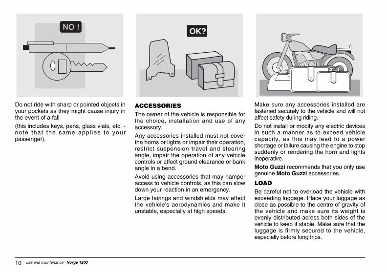
ke sure any accessories installed aretened securely to the vehicle and will notect safety during riding.
not install or modify any electric devicessuch a manner as to exceed vehiclepacity, as this may lead to a powerortage or failure causing the engine to stopddenly or rendering the horn and lightsperative.
to Guzzi recommends that you only usenuine Moto Guzzi accessories.
AD careful not to overload the vehicle withceeding luggage. Place your luggage asse as possible to the centre of gravity of vehicle and make sure its weight is
enly distributed across both sides of thehicle to keep it stable. Make sure that thegage is firmly secured to the vehicle,
pecially before long trips.
GUZum_norge1200#06_###e.book Page 10 Saturday, May 27, 2006 12:55 PM
use and maintenance Norge 120010
Do not ride with sharp or pointed objects inyour pockets as they might cause injury inthe event of a fall
(this includes keys, pens, glass vials, etc. -note that the same appl ies to yourpassenger).
ACCESSORIESThe owner of the vehicle is responsible forthe choice, installation and use of anyaccessory.
Any accessories installed must not coverthe horns or lights or impair their operation,restrict suspension travel and steeringangle, impair the operation of any vehiclecontrols or affect ground clearance or bankangle in a bend.
Avoid using accessories that may hamperaccess to vehicle controls, as this can slowdown your reaction in an emergency.
Large fairings and windshields may affectthe vehicle's aerodynamics and make itunstable, especially at high speeds.
Mafasaff
Doin cashsuino
Moge
LOBeexclotheevveluges

11use and maintenance Norge 1200
Do not exceed the maximum load capacityof each luggage rack.
The overloaded vehicle wil l becomeunstable and handle poorly.
KG!
GUZum_norge1200#06_###e.book Page 11 Saturday, May 27, 2006 12:55 PM
Avoid fixing bulky, heavy and/or dangerousobjects to the handlebars, mudguards andforks - this could slow down the vehicle'sresponse in turns and would inevitablyaffect handling.
Do not secure bulky bags to the vehiclesides, as they could hit people or obstacleswhen riding, resulting in loss of control.
Do not carry any luggage unless firmlysecured to the vehicle.
Do not carry any bags which protrude toomuch over luggage rack or cover the lights,horn or indicators.
Do not carry pets or children sitting on theglove compartment or on the luggage rack.

) Rear shock absorber) Left rider footpeg) Gear shift lever) Centre stand) Side stand) Engine oil dipstick) Fairing lug (if fitted)
13
12
11
GUZum_norge1200#06_###e.book Page 12 Saturday, May 27, 2006 12:55 PM
use and maintenance Norge 120012
POSITION OF KEY COMPONENTS - KEY
KEY1) Headlight2) Instrument panel3) Left rear-view mirror4) Fuel tank filler plug5) Fuel tank6) Left side body panel7) ABS fuse carrier
8) Battery9) Passenger/rider seat
10) Passenger grab handle11) Tool kit compartment12) Rear phonic wheel13) Left passenger footpeg 14) Seat lock
15161718192021
1 2 3 4
192021 18 17 16 15 14
5 6 1097 8
13use and maintenance Norge 1200
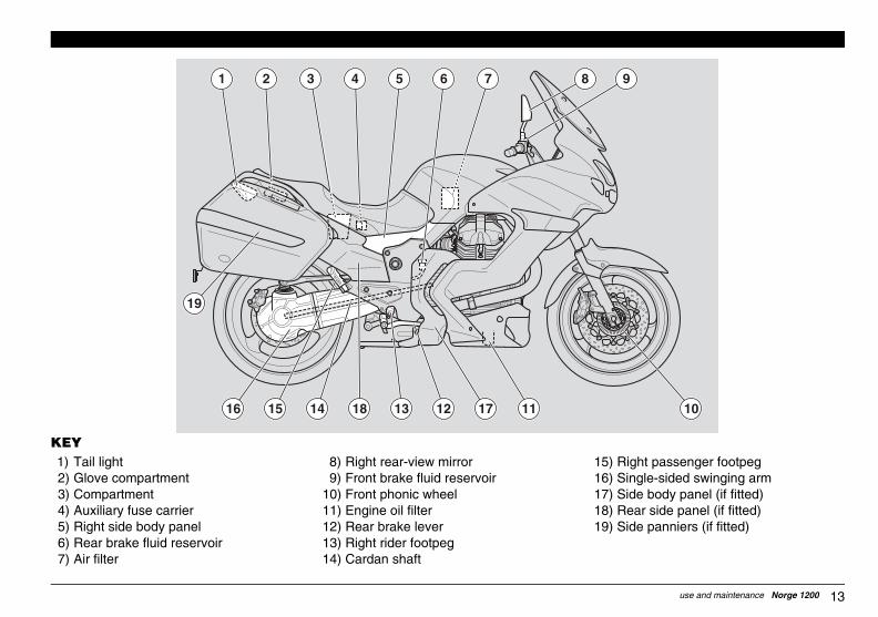
15) Right passenger footpeg16) Single-sided swinging arm17) Side body panel (if fitted)18) Rear side panel (if fitted)19) Side panniers (if fitted)
10
9
GUZum_norge1200#06_###e.book Page 13 Saturday, May 27, 2006 12:55 PM
KEY1) Tail light2) Glove compartment3) Compartment4) Auxiliary fuse carrier5) Right side body panel6) Rear brake fluid reservoir7) Air filter
8) Right rear-view mirror9) Front brake fluid reservoir
10) Front phonic wheel11) Engine oil filter12) Rear brake lever13) Right rider footpeg14) Cardan shaft
1 5
1816
19
15 14 13 12 17 11
6 82 3 4 7

/off switch (if fitted)
6)
6
7
4
5
GUZum_norge1200#06_###e.book Page 14 Saturday, May 27, 2006 12:55 PM
use and maintenance Norge 120014
LOCATION OF INSTRUMENTS/CONTROLS
LOCATION OF INSTRUMENTS/CONTROLS - KEY1) Clutch lever2) Instruments and indicators3) Ignition/steering lock switch ( - - )4) Front brake lever5) Throttle grip6) Hazard button ( )7) Engine run/kill switch ( - - )8) Dimmer switch ( - )
9) Handgrips heating on10) Horn button (*)11) Turn indicator switch (12) MODE switch13) (ABS) disabling switch
8
9
12
10 11
2
1
313

15use and maintenance Norge 1200
2) Red antitheft light3) Red gear shift light
12
11
7
GUZum_norge1200#06_###e.book Page 15 Saturday, May 27, 2006 12:55 PM
INSTRUMENTS AND INDICATORS
LOCATION OF INSTRUMENTS/CONTROLS - KEY1) Green turn indicator warning light ( )2) Amber ABS light ( ) (Anti-lock
Braking System)3) Red alarm light4) Green neutral light ( )5) Amber "stand down" light ( )6) Blue high beam warning light ( )7) Amber low fuel warning light ( )
8) Multifunction digital display(C lock , amb ien t tempera tu re ,Odometer, trip data, Lap timer, alarmd isp lay , ma in tenance warn ingindicator)
9) Speedometer10) Rev counter11) Fuel level indicator
11
109
8
13
1 2 3 4 5 6 1
ABS
e same time when the emergency button is
d on, it stays on until speed is above 5 km/h,
e ABS is automatically disabled, because this be the case, contact a Moto Guzzi
n and immobilizer.he engine is started or comes on duringns that the electronic control unit hasthorised Dealer. If this comes on and theeans that the engine oil pressure in the
t a Moto Guzzi Authorised Dealer.
h the high beam.
isplay shows the distance covered since the
ge 34 (FUEL).
Continued
GUZum_norge1200#06_###e.book Page 16 Saturday, May 27, 2006 12:55 PM
use and maintenance Norge 120016
INSTRUMENTS AND INDICATORS TABLE
Description Function
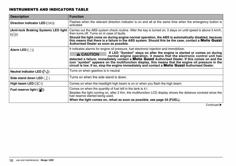
Direction indicator LED ( ) Flashes when the relevant direction indicator is on and all at thactivated
(Anti-lock Braking System) LED light( )
Carries out the ABS system check routine. After the key is turnethen turns off. Turns on in case of faults.Should the light come on during engine normal operation, ththis means that there is a failure in the ABS system. ShouldAuthorised Dealer as soon as possible.
Alarm LED ( ) It indicates alarms for engine oil pressure, fuel electronic injectio If LED "Symbol" stays on after tnormal engine operation, it mea
detected a failure; immediately contact a Moto Guzzi Auicon "symbol" appears on the multifunction display, this mcircuit is low. If so, stop the engine immediately and contac
Neutral indicator LED ( ) Turns on when gearbox is in neutral
Side stand down LED ( ) Turns on when the side stand is down.
High beam LED ( ) Comes on when the headlight high beam is on or when you flas
Fuel reserve light ( ) Comes on when the quantity of fuel left in the tank is 4 l.Besides the light coming on, after 2 Km, the multifunction LCD dfuel reserve started being used.When the light comes on, refuel as soon as possible, see pa
ABS
!
CAUTION

17use and maintenance Norge 1200
a display, see page 18 (MULTIFUNCTION LCD
left corner of the display. When temperature isnge in °C or °F is selected through the display,
mi is selected through the display, see page 18
is shown in the middle while at the bottom is onensumption, Maximum speed or Average speed,
, "Menu", "Battery voltage". Should the bike beble to enter the "Menu" function. See page 18
on the instrument panel will come on.
ber one, as soon as the level is decreasing theeans that there is less than 5 Ø 1 l of fuel in the
d can be set through the display, see page 21
arning lights (turn indicators) are flashing.
DASH PANEL).
ndgrips heating. Press briefly to adjust heating. 28 (CONTROLS ON THE DASH PANEL).
GUZum_norge1200#06_###e.book Page 17 Saturday, May 27, 2006 12:55 PM
Mul t i funct ionLCD display
Clock Displays time in 12 or 24 hour format. Format is selected viDISPLAY).
TemperatureDisplays ambient temperature, the value is shown in the topclose to 3° C (37 °F) the ice symbol should be displayed. Rasee page 18 (MULTIFUNCTION LCD DISPLAY).
Odometer (km/mi) Gives total distance covered (in km or miles). Range in km or(MULTIFUNCTION LCD DISPLAY).
Trip info TRIP 1 and2
Gives data concerning Trip 1 and 2, partial distance covered of the following: Trip time, Fuel consumption, Instant fuel cosee page 18 (MULTIFUNCTION LCD DISPLAY).
ModeIn this position access is given to the functions: "Lap timer"running and the speed be different from zero, it is impossi(MULTIFUNCTION LCD DISPLAY).
Speedometer Indicates road speed.
Rev counter (rpm) Indicates engine rpm.When maximum rpm set is exceeded, the red gear shift light
Fuel level indicator Gives fuel level in the tank. With full tank the index points numindex will move down. When the light " " comes on, this mtank. If so, refuel as soon as possible, see page 34 (FUEL).
Antitheft LED Indicates that option external antitheft system is available.
Gear shift indicator LED Comes on when set rpm are exceeded. Activation threshol(GEAR SHIFT INDICATOR).
“HAZARD” EMERGENCY PUSH-BUTTON
Turns on when pressed. It indicates that all four emergency w
ABS switch For disabling procedure see page 28 (CONTROLS ON THE
Heated handgrips switch (if fitted) With engine running, press for several seconds to activate haPress again for several seconds to turn heating off. See page
Description Function
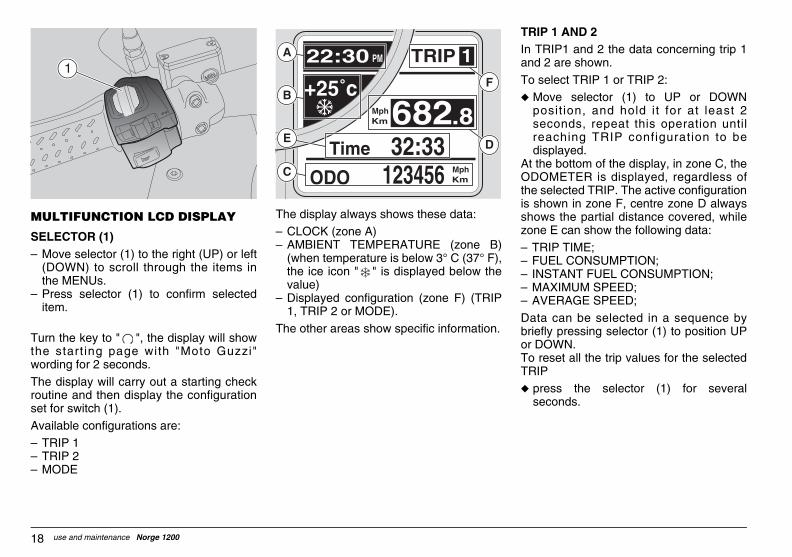
IP 1 AND 2TRIP1 and 2 the data concerning trip 1d 2 are shown.
select TRIP 1 or TRIP 2:Move selector (1) to UP or DOWNposit ion, and hold i t for at least 2seconds, repeat this operation untilreaching TRIP configuration to bedisplayed. the bottom of the display, in zone C, the
OMETER is displayed, regardless of selected TRIP. The active configuration
shown in zone F, centre zone D alwaysows the partial distance covered, whilene E can show the following data:
TRIP TIME; FUEL CONSUMPTION;INSTANT FUEL CONSUMPTION;MAXIMUM SPEED; AVERAGE SPEED;
ta can be selected in a sequence byefly pressing selector (1) to position UPDOWN. reset all the trip values for the selectedIP
press the selector (1) for severalseconds.
GUZum_norge1200#06_###e.book Page 18 Saturday, May 27, 2006 12:55 PM
use and maintenance Norge 120018
MULTIFUNCTION LCD DISPLAY
SELECTOR (1)√ Move selector (1) to the right (UP) or left
(DOWN) to scroll through the items inthe MENUs.
√ Press selector (1) to confirm selecteditem.
Turn the key to " ", the display will showthe start ing page with "Moto Guzzi"wording for 2 seconds.
The display will carry out a starting checkroutine and then display the configurationset for switch (1).
Available configurations are:√ TRIP 1√ TRIP 2√ MODE
The display always shows these data:√ CLOCK (zone A)√ AMBIENT TEMPERATURE (zone B)
(when temperature is below 3° C (37° F),the ice icon " " is displayed below thevalue)
√ Displayed configuration (zone F) (TRIP1, TRIP 2 or MODE).
The other areas show specific information.
TRIn an
Tou
AtODtheis shzo
√√√√√
Dabrior ToTRu
1F
C
DE
B
A

19use and maintenance Norge 1200
LAP TIMERWhen the vehicle is on a track, the laptimer allows the user to measure the laptime and store data that can be laterretrieved.To enter the LAP TIMER function:
u Confirm selection on CHRONO bypressing the selector (1) for severalseconds.
The display will show the following options:
√ EXIT√ TIMING√ VIEW TIMES√ DELETE TIMES;Options can be selected in a sequence bybriefly pressing the selector (1).
u To exit this function, confirm the EXIToption by pressing the selector (1) forseveral seconds.
GUZum_norge1200#06_###e.book Page 19 Saturday, May 27, 2006 12:55 PM
Should the heated handgrips be fitted (iffitted) and active, the display will show aspecial icon, instead of the selected TRIP,and the TRIP indication is given in the areabelow. The icon identifies three levels ofheating.
MODEMODE configuration features the functionsallowing the user to interact with thesystem.To enter the MODE function:
u Move selector (1) to UP or DOWNposit ion, and hold i t for at least 2seconds, repeat this operation untilreaching MODE configuration.
Briefly move selector (1) to position UP orDOWN to cyclically display the followingfunctions:√ LAP TIMER;√ MENU (function disabled when vehicle is
in motion);√ BATTERY VOLTAGE;

LETE TIMES s function deletes the acquired laps.
delete data:ress the selector (1) for severaleconds.a deletion is to be confirmed. e done, the display will go back to LAPER function.
GUZum_norge1200#06_###e.book Page 20 Saturday, May 27, 2006 12:55 PM
use and maintenance Norge 120020
TIMING To turn on the TIMING:u confirm selection on TIMING by pressing
the selector (1) for several seconds.The display will show the actual value andthe previous three values stored. To theleft of the value is the lap number.
To start the timing:u Briefly press the selector (1).If you press the selector (1) again withinthe first 10 seconds from when the timerstarts recording, the lap timer will reset.
After 10 seconds, if you push it again, thedata will be stored and the next lap timerwill start recording.
Press the selector (1) for several secondsto cancel the lap timer session. Thecounter on the display is reset. Brieflypress the selector (1) to restart thesession.
To go back to LAP TIMER:
u Press the selector (1) for severalseconds.
NOTE 40 is the maximum number ofsessions that can be recorded, further datacan be stored only if the previous set isdeleted. Data acquisition stops when key is turnedoff. When key is turned back on, althoughthe display will not be set to LAP TIMERfunction the data are stored in the memory,therefore the following data acquired willfollow the previous sessions stored.Stored data wil l be lost i f battery isdisconnected.
VIEW TIMES This function also displays the acquired laptimes.
To enable VIEW TIMES option:u Confirm selection on "VIEW TIMES" by
pressing the selector (1) for severalseconds.
To scroll the pages:u Briefly press the selector (1).To go back to LAP TIMER:
u Press the selector (1) for severalseconds.
DEThitime
To u p
sDatOncTIM

21use and maintenance Norge 1200
IME SETTINGS his function allows you to set the clock.
o enter the TIME SETTINGS function:
Confirm selection on TIME SETTINGSby pressing the selector (1) for severalseconds.
o set the hour value:Briefly press the selector (1) to increasehour value that is increased by one unitevery time the push-button is pressed.Press the selector (1) for severalseconds to shift to minute setting; pressit briefly to increase value, value isincreased by one unit every time thepush-button is pressed.
o store the set data and go back toETTINGS function:
press the selector (1) for severalseconds.
EAR SHIFT INDICATORhis function allows you to set the value fore Gear shift indicator threshold.
o enter the GEAR SHIFT INDICATORnction:
Confirm selection on GEAR SHIFTINDICATOR by pressing the selector (1)for several seconds.
he display shows "Gear shift indicator"nd the rev counter scale indicates thereshold value currently set.
GUZum_norge1200#06_###e.book Page 21 Saturday, May 27, 2006 12:55 PM
MENUThis function can be selected only whenvehicle is stopped. It allows the user to setthe layout for displaying the parameters ofthe various configurations.To enter the MENU function:
u With the MODE configuration displayed,confirm selection on MENU by pressingthe selector (1) for several seconds.
The display will show the following options:
√ EXIT√ SETTINGS√ DIAGNOSIS (function can be accessed
only by authorised personnel)√ LANGUAGE;Options can be selected in a sequence bybriefly pressing the selector (1).
SETTINGSThis funct ion al lows you to set andcustomise the layout of the parameters tobe displayed for the various configurations.
To enter the SETTINGS function:u Confirm selection on SETTINGS by
pressing the selector (1) for severalseconds.
The display will show the following options:
√ EXIT√ TIME SETTINGS√ GEAR SHIFT INDICATOR √ BACK LIGHTING√ °C/°F√ KM/MILES√ 12H/24H√ IMMOBILIZER LED√ CHANGE THE CODE Options can be selected in a sequence bybriefly pressing the selector (1).
TT
T
u
Tu
u
TS
u
GTth
Tfu
u
Tath
EXIT
SETTINGS
DIAGNOSIS
LANGUAGE

store the set unit and go back toTINGS function:
ress the selector (1) for severaleconds.
/24Hs function allows you to select the time
at.
enter the 12H/24H function:onfirm selection on "12H/24H" byressing the selector (1) for severaleconds. display shows two formats:
2H4H formats can be selected by briefly
ssing selector (1).
store the chosen format and go back toTINGS function:
ress the selector (1) for severaleconds.
OBILIZER LEDs function allows you to enable/disable alarm led flashing inside the fuel levelge indicator.
used in case an external antithefttem is connected to the vehicle.
ANGE THE CODE
ws the user to change his personale. During the procedure the user is
mpted to enter the old code.
GUZum_norge1200#06_###e.book Page 22 Saturday, May 27, 2006 12:55 PM
use and maintenance Norge 120022
To set the Gear shift indicator threshold:u Briefly press the selector (1) to increase
threshold value by 100 rpm at a time. Assoon as the value reaches the maximumlimit, it is decreased by the same amountif the selector (1) is pressed again.
To store the set threshold and go back toSETTINGS function:
u press the selector (1) for severalseconds.
The set value is stored until it is set again.
NOTE When the threshold is exceeded,the red light in the rev counter flashes; takeengine rpm below threshold value and thered light should go off.
BACK LIGHTINGThis function allows the user to adjust thelighting power of the instrument panel.To enter the BACK LIGHTING function:
u Confirm selection on BACK LIGHTINGby pressing the selector (1) for severalseconds.
The display shows three levels for lightingintensity:√ LOW√ MEAN√ HIGHLevels can be selected in a sequence bybriefly pressing the selector (1).
To store the set level and go back toSETTINGS function:u press the selector (1) for several
seconds.
°C/°FThis function allows you to select the unitof measurement for ambient temperature.To enter the °C/°F function:u Confirm selection on °C/°F by pressing
the selector (1) for several seconds.The d isp lay shows two un i t s o fmeasurement:√ °C√ °FUnits of measurement can be selected in asequence by briefly pressing the selector(1).To store the selected range and go back toSETTINGS function:u press the selector (1) for several
seconds.
KM/MILESThis function allows you to select the unitof measurement for speed.To enter the "KM/MILES" function:u Confirm selection on "KM/MILES" by
pressing the selector (1) for severalseconds.
The d isp lay shows two un i t s o fmeasurement:√ KM√ MILESUnits of measurement can be selected in asequence by briefly pressing the selector(1).
To SET
u ps
12HThiform
To u C
ps
The
√ 1√ 2Thepre
To SET
u ps
IMMThithegau
It issys
CH
Allocodpro

23use and maintenance Norge 1200
SERVICE When the vehicle is due for maintenance(after the first 1000km - 625 mi and thenevery 10000km 6250 mi) the display willshow the icon of a wrench ≈ ∆ in the areadedicated to the ice icon. Should bothicons be active, they will be displayedalternately.
GUZum_norge1200#06_###e.book Page 23 Saturday, May 27, 2006 12:55 PM
CODE RECOVERY
Allows the user to set a new user codewhen the old one is not available. Duringthe procedure the user is prompted toinsert 2 of the programmed keys.
DIAGNOSISThis function interfaces with the systemsfit ted to the motorcycle to carry outdiagnosis. To enable the function, apassword is needed that is available onlyto Moto Guzzi service centres.
LANGUAGE;This function allows you to choose thelanguage of any message displayed.
To enter the LANGUAGE function:
u Confirm selection on LANGUAGE bypressing the selector (1) for severalseconds.
Available languages are:√ ITALIANO√ ENGLISH√ FRANCAIS√ DEUTSCH√ ESPAGNOLThe languages can be selected by brieflypressing selector (1).To store the set unit and go back toLANGUAGE function:
u press the selector (1) for severalseconds.
BATTERY VOLTAGEThis function shows battery voltage anddoes not allow the user to interact.
To enter the function:
u From the MODE configuration,repeatedly press the selector (1) until thedesired page is displayed.

COVERED W/FUEL RESERVEhen the fuel reserve light is steadily on, display indicates the km covered in this
ndition. The value is displayed in area C,ere the ODOMETER usually is.he vehicle is using the fuel reserve when engine is started, kilometres covered
th fuel reserve on are displayed after 40conds f rom eng ine s tar t -up , theOMETER can be viewed this way asll.
GUZum_norge1200#06_###e.book Page 24 Saturday, May 27, 2006 12:55 PM
use and maintenance Norge 120024
ALARM DISPLAYIf a serious failure is detected --somethingthat might jeopardise the vehicle or therider's safety-- the display will show an iconindicating the cause of the failure, in thearea where the odometer usually is.
A la rms a re d iv ided in two g roupsdepending on their priority:√ High priority:u Oil pressure, Errors from control unit,
Errors from instrument panel.
√ Low priority:u Direction indicators, Control unit
disconnected. If there are many alarms with the samepriority level, the relevant icons aredisplayed alternately.
High priority alarms do not allow you todisplay low priority ones.
KMWthecowhIf tthewiseODwe

25use and maintenance Norge 1200
GUZum_norge1200#06_###e.book Page 25 Saturday, May 27, 2006 12:55 PM
LOCATION OF ACCESSORIES (if any)
LOCATION OF ACCESSORIES - KEY1) lower fairing lug2) Tom Tom satellite navigation system3) heated handgrips4) side body panel5) rear side body panel6) Plug-in socket7) side panniers kit8) top case
52
1
6 73 4 8

PLUG-IN SOCKETInside the underseat compartment is a12V power socket.The power outlet can be used to powerelectric items with power not above180 W (mobile phone, inspection lamp,etc.).
CAUTIONing the power outlet for a long timeth engine stopped could completelycharge the battery.
SIDE PANNIERS KITTOP CASE
GUZum_norge1200#06_###e.book Page 26 Saturday, May 27, 2006 12:55 PM
use and maintenance Norge 120026
ACCESSORIES (if any)
It is possible to install on this vehicle thefollowing accessories, which in someversions are already available as standard.
NOTE The electric components onlyoperate when the ignition switch is in the≈ ∆ position.
1) LOWER FAIRING LUGPlease see page 47 (REMOVINGTHE LUG) for instructions on how toremove the lower fairing lug.
2) TOM TOM SATELLITENAVIGATION SYSTEMThe Tom Tom satellite navigationsystem uses touch-screen technology.Please see the attached user's manualfor instructions on the use of the TomTom navigation system.
3) HEATED HANDGRIPSPress the push-button for several secondsto activate handgrips heating. Press brieflyto adjust heating. Press again for severalseconds to turn heating off. When theengine is stopped, the handgrip heatingswitches off, too; it will turn on again whenthe engine is started again, and will be setto last selected power level.4) SIDE BODY PANEL
(foot protection)Please see page 47 (REMOVINGTHE RIGHT SIDE BODY PANEL) forinstructions on how to remove the sidebody panel.
5) REAR SIDE BODY PANELTo remove the rear side body panel,see page 47 (REMOVING THE REARLEFT SIDE BODY PANEL).
6)
Uswidis
7)8)

27use and maintenance Norge 1200
CONTROLS ON RIGHT HANDLEBAR
NOTE The electric components onlyoperate when the ignition switch is in the" " position.
6) RUN/KILL SWITCH ( - - )Set switch to position and press it toposition to start the engine: thestarter motor cranks the engine. Seepage 53 (STARTING) for the startingprocedure.
Set it to position to stop the engine.
WARNINGDo not set the switch to while riding.
6
7
GUZum_norge1200#06_###e.book Page 27 Saturday, May 27, 2006 12:55 PM
MAIN INDEPENDENT CONTROLS
CONTROLS ON LEFT HANDLEBAR
NOTE The electric components onlyoperate when the ignition switch is in the" " position.
1) HORN BUTTON ( )Press it to operate the horn.
2) DIRECTION INDICATORS SWITCH( )Move the switch to the left, beforeturning left; move it to the right beforeturning right.Push in to cancel the indicators afterturning.
3) MODE BUTTONMove the MODE joyst ick to theleft/right or press it to respectivelyscroll UP/DOWN and select the pageson the multifunction display.
4) LIGHT DIMMER SWITCH ( - )In pos i t ion " " pa rk ing l i gh ts ,instrument panel light and low beamare always on.In position " " -left- the high beam ison.In position " " -right- the passing lightis activated, to be used in case ofdanger or emergency situations.
5) HANDGRIP HEATING ON/OFFSWITCH (if fitted)Press it to switch handgrip heating on.
3 2
1 5
4

-enable the ABS as follows:top the vehicle and the engine setting
he ignition switch to " ".ake the ignition switch back to ≈ ≈ andtart the engine.ith engine running, the ABS will be re-
nabled when speed gets above 5 km/h.
TE In case of failure or when ABS isabled, the motorcycle acts as if it is notuipped with this system.
GUZum_norge1200#06_###e.book Page 28 Saturday, May 27, 2006 12:55 PM
use and maintenance Norge 120028
CAUTIONWith the engine stopped and the switchin position " ", the battery may weardown.
With vehicle stopped, stop the engine andleave switch set to position " ".7) HAZARD SWITCH ( )
Press it to activate all turn indicators.This funct ion can be enabled ordisabled only if ignition switch is set toposition " ". Once activated, the turnindicators stay on even if key is turnedoff. To disable them, set ignition switchto " ".
CONTROLS ON THE DASH PANEL
NOTE The electric components onlyoperate when the ignition switch is in the" " position.
1) ABS DISABLING SWITCHDisable the system as follows:
u Take the ignition switch to " " and startthe engine. It is recommended to disablethe ABS while engine is running, withvehicle stopped.
u Press and hold the SET (1) push-buttonfor several seconds.After about three seconds the light onthe instrument panel will start blinking.
u Immediately release push-button (1).u Now the ABS light on the panel will carry
on blinking slowly meaning that the ABSis completely disabled.
Reu S
tu T
su W
e
NOdiseq
1

29use and maintenance Norge 1200
Position Function Key removal
Steering lock
The steeringis locked. I t i s no tposs ib le tos ta r t theeng ine o rswitch on thelights.
It is possibleto remove thekey.
Ne i the r theeng ine , no rthe lights willoperate.
It is possibleto remove thekey.
The eng ineand the lightscan beoperated.
I t i s no tposs ib le toremove thekey.
The eng inecan no t bes ta r ted andthe park inglights are on
It is possibleto remove thekey.
GUZum_norge1200#06_###e.book Page 29 Saturday, May 27, 2006 12:55 PM
IGNITION SWITCHThe ignition switch (1) is mounted to thetop yoke of the steering shaft.
NOTE The key operates the ignitionswitch/steering lock, the fuel tank lock andthe seat lock.
Two keys are supplied together with thevehicle (one spare key).
NOTE Store the spare key in a safeplace (other than the vehicle).
NOTE It is possible to program up to 4keys. It is advisable to contact a MotoGuzz i Author i sed Dea le r fo r th i sprocedure.
STEERING LOCK
WARNINGNever turn the key to position " "when riding, or you will lose control ofthe vehicle.
OPERATION
To lock the steering:u Turn the handlebar fully to the left.u Turn the key to " ".u Press the key in and turn it to ≈ ∆
position.
NOTE If necessary, turn on the parkinglights, see page 30 (PARKING LIGHTS).
u Remove the key.
1

GUZum_norge1200#06_###e.book Page 30 Saturday, May 27, 2006 12:55 PM
use and maintenance Norge 120030
PARKING LIGHTSThe vehicle is equipped with front and rearparking lights. It is always recommended topark the vehicle in the suitable areas and inany case in lighted locations. If this is notpossible, the parking lights are usefulwhenever it is necessary to park in a darkor poorly lit area and in any case to makethe vehicle more visible.
OPERATION
To turn the parking lights on:
u Lock the steering but do not remove thekey (1), see page 29 (STEERINGLOCK).
u Turn the key (1) to ≈ ∆ (PARKING)position.
u Check that both front and rear parkinglights are on.
u Remove the key (1).
CAUTIONThe parking lights drain the battery. Donot leave them on for long periods oftime to avoid the battery from wearingdown. A dead battery prevents you fromstarting the vehicle.
1
31use and maintenance Norge 1200
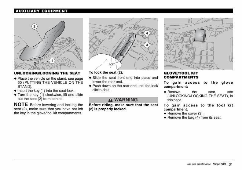
GLOVE/TOOL KIT COMPARTMENTSTo ga in access to the g lovecompartment:u Remove the seat, see
(UNLOCKING/LOCKING THE SEAT), inthis page.
To ga in access to the tool k i tcompartment:u Remove the cover (3).u Remove the bag (4) from its seat.
GUZum_norge1200#06_###e.book Page 31 Saturday, May 27, 2006 12:55 PM
AUXILIARY EQUIPMENT
UNLOCKING/LOCKING THE SEAT u Place the vehicle on the stand, see page
60 (PUTTING THE VEHICLE ON THESTAND).
u Insert the key (1) into the seat lock.u Turn the key (1) clockwise, lift and slide
out the seat (2) from behind.
NOTE Before lowering and locking theseat (2), make sure that you have not leftthe key in the glove/tool kit compartments.
To lock the seat (2):u Slide the seat front end into place and
lower the rear end.u Push down on the rear end until the lock
clicks shut.
WARNINGBefore riding, make sure that the seat(2) is properly locked.
1
2
3
4
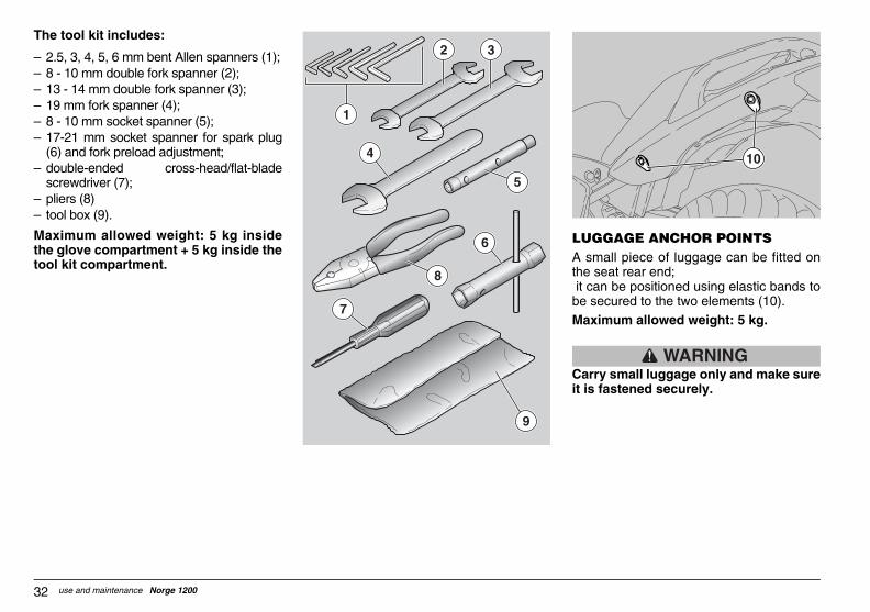
GGAGE ANCHOR POINTS small piece of luggage can be fitted on seat rear end;
can be positioned using elastic bands to secured to the two elements (10).ximum allowed weight: 5 kg.
WARNINGrry small luggage only and make sures fastened securely.
10
GUZum_norge1200#06_###e.book Page 32 Saturday, May 27, 2006 12:55 PM
use and maintenance Norge 120032
The tool kit includes:
√ 2.5, 3, 4, 5, 6 mm bent Allen spanners (1);√ 8 - 10 mm double fork spanner (2);√ 13 - 14 mm double fork spanner (3);√ 19 mm fork spanner (4);√ 8 - 10 mm socket spanner (5);√ 17-21 mm socket spanner for spark plug
(6) and fork preload adjustment;√ double-ended cross-head/flat-blade
screwdriver (7);√ pliers (8)√ tool box (9).
Maximum allowed weight: 5 kg insidethe glove compartment + 5 kg inside thetool kit compartment.
LUA the it beMa
Cait i
9
5
6
8
7
2 3
1
4

33use and maintenance Norge 1200
GUZum_norge1200#06_###e.book Page 33 Saturday, May 27, 2006 12:55 PM
WINDSCREEN ADJUSTMENTManually adjust the windscreen position asfollows:
√ support the windscreen and, working oneither side, loosen the two knobs (1).
√ set desired windscreen position.√ support the windscreen and, working on
either side, tighten the two knobs (1).
1

ter refuelling:
OTE The plug can only be closeden the key (2) is inserted.
With the key (2) inserted, press the plugand tighten.
WARNINGke sure the plug is firmly closed.
Remove the key (2).Close the flap (1).
2 1
3
GUZum_norge1200#06_###e.book Page 34 Saturday, May 27, 2006 12:55 PM
use and maintenance Norge 120034
MAIN COMPONENTS
FUEL
WARNINGThe fuel used in internal combust ion engines is highlyflammable and can become explosiveunder particular conditions. It is important to refuel and service thevehicle in a well-ventilated area, withthe engine off. Do not smoke while refuelling or nearfuel vapours, in any case avoid contactwith naked flames, sparks and anyother heat source or source of ignitionto prevent fires or explosion. Avoid spilling fuel, as it may ignitewhen in contact with hot engine parts. In the event of accidental spillage,make sure that the area has completelydried before starting the engine.Never fill the tank to the rim, as fuelexpands from heat and when left underdirect sunlight. Tighten the filler plug securely afterrefuelling. Avoid contact with skin, donot inhale fuel vapours; do not swallowfuel or transfer it between differentreceptacles using a hose.
DO NOT RELEASE FUEL IN THEENVIRONMENT.
KEEP AWAY FROM CHILDREN.
Use only premium grade unleaded petrolwith 95 RON and 85 MON octane ratingminimum.
To refuel, proceed as follows:u Raise the flap (1).u Insert the key (2) into the tank plug lock
(3).u Turn the key clockwise, pull and open
the fuel flap.
FUEL TANK CAPACITY (reserve included): 23 bTANK RESERVE: 4 b
CAUTIONDo not add any additives or othersubstances to the fuel.If you use a funnel or other tools, makesure that they are perfectly clean.
WARNINGDo not fill the tank up to the rim. Fuellevel must always remain below thelower edge of the filler neck (see figure).
u Refuel.
Af
Nwh
u
Ma
u
u

35use and maintenance Norge 1200
WARNINGIn the event of accidental contact, flushaffected area thoroughly. If fluid hasbeen spilled in the eyes, seek theassistance of an ophthalmologist or adoctor.DO NOT RELEASE INTO THEENVIRONMENT.KEEP AWAY FROM CHILDREN.
CAUTIONWhen handling brake fluid, take carenot to spill it on plastic or painted parts,or they will damage.
GUZum_norge1200#06_###e.book Page 35 Saturday, May 27, 2006 12:55 PM
BRAKE FLUID - recommendations
NOTE This vehicle is equipped withfront and rear disc brakes operated byindependent hydraulic circuits.
The following information applies to bothbraking systems.
WARNINGSudden changes in brake lever play or aspongy feel of the lever may indicateproblems with the hydraulic system.Please contact a Moto GuzziAuthorised Dealer in case you have anydoubts on the operation of the brakingsystem and in case you are not able tocarry out the normal checks.
WARNINGEnsure that the brake discs have notbecome contaminated with oi l orgrease, especially after maintenance orinspections.Check that the brake hoses are nottwisted or worn.Prevent water or dust from accidentallygetting into the circuit.Wear latex gloves when servicing thehydraulic circuit.Brake fluid can cause severe irritationin the event of contact with eyes or skin.

OTE Halve maintenance intervals ifu are riding in rainy or dusty conditions, rough road surfaces or when the vehicleused in competitions.eck the brake discs for wear after thet 1000 km (625 mi) and then every 2000 (1250 mi).fore leaving, check brake fluid level in
e reservoirs, see page 37 (FRONTAKE), page 38 (REAR BRAKE), andke pad wear, see page 76 (CHECKINGE BRAKE PADS FOR WEAR).ve the brake fluid changed every 20000 (12500 mi) or every two years by ato Guzzi Authorised Dealer.
WARNING not use the vehicle if the braking
stem is leaking fluid.
GUZum_norge1200#06_###e.book Page 36 Saturday, May 27, 2006 12:55 PM
use and maintenance Norge 120036
DISC BRAKES
WARNINGThe brakes are key safety componentsand must be kept in perfect workingorder; check them before each ride.A dirty disc will soil the pads, leading toloss of braking efficiency. Dirty pads must be replaced, while dirtydiscs must be cleaned with a high-quality degreaser.Have brake fluid changed every twoyears by a Moto Guzzi AuthorisedDealer.Use the brake fluid recommended in thelubr icants tab le , see page 99(LUBRICANT CHART).
NOTE This vehicle is equipped withfront and rear disc brakes operated byindependent hydraulic circuits.
The front brake is a twin-disc brake (onedisc on either side of the wheel).
The rear brake uses a single disc (fitted tothe right side of the wheel).
The following information applies to bothbraking systems.Brake fluid level decreases as the brakepads wear down.
The front brake reservoir is located on theright handlebar, close to the front brakelever fitting.
The rear brake reservoir is located on thevehicle right side, close to the rear brakecontrol lever.
Nyoonis ChfirskmBethBRbraTHHakmMo
Dosy

37use and maintenance Norge 1200
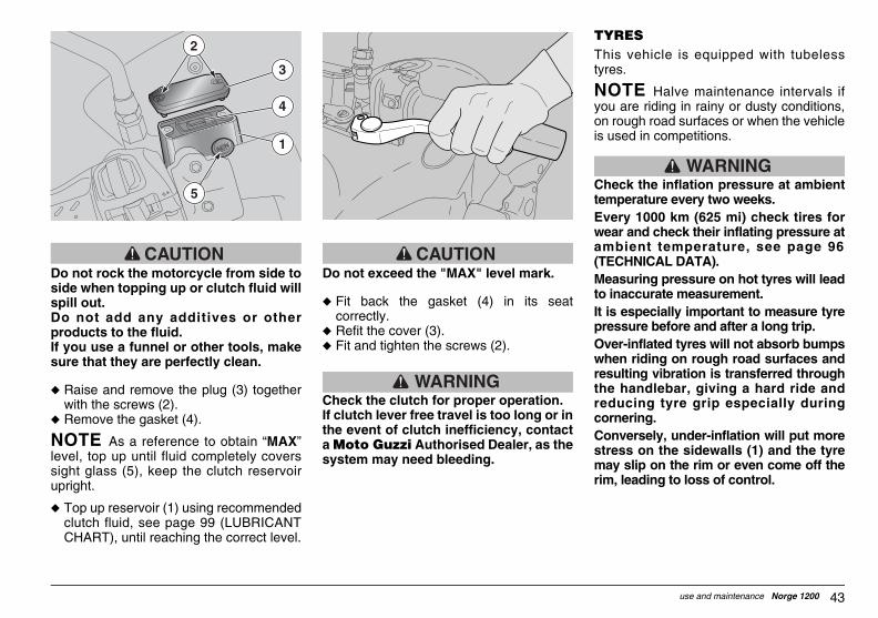
u Top up reservoir (2) with recommendedbrake fluid, see page 99 (LUBRICANTCHART), until reaching correct level thatis in-between the marks ≈MIN∆ and≈MAX∆.
CAUTIONDo not exceed the "MAX" level mark.
Top up to "MAX" level only afterchanging the brake pads.
If topped up to "MAX" level with wornpads, brake fluid will spill out when youchange the pads at a later time.
Check the brake for proper operation.
If brake lever travel is too long or in theevent of loss of braking, contact a MotoGuzzi Authorised Dealer, as the systemmay need bleeding.
GUZum_norge1200#06_###e.book Page 37 Saturday, May 27, 2006 12:55 PM
FRONT BRAKECHECKu Place the vehicle on the stand, see page
60 (PUTTING THE VEHICLE ON THESTAND).
u Turn the handlebar fully to the right.u Make sure that the fluid level exceeds
the "MIN" mark.MIN= minimum levelMAX= maximum level
If the fluid is below the "MIN" mark:
CAUTIONBrake fluid level decreases as the brakepads wear down.u Check brake pad wear, see page 76
(CHECKING THE BRAKE PADS FORWEAR) and disc wear.
If the pads and/or the disc do not needreplacing, top up fluid level.
TOPPING UP
Carefully read page 35 (BRAKE FLUID -recommendations).
CAUTIONBrake fluid may spill out. Do not operatethe front brake lever if the screws (1)have been loosened or, most important,with the brake fluid reservoir plugremoved.
u Unscrew the two screws (1) of the brakefluid reservoir (2) using a cross-headscrewdriver.
WARNINGAvoid prolonged exposure of brakefluid to air.Brake fluid is hygroscopic and willabsorb moisture from the air. Keep the brake fluid reservoir openJUST LONG ENOUGH to top up level.u Lift and remove the cover (3) with
screws (1) and protection (4).u Remove the gasket (5).
CAUTIONDo not rock the vehicle from side toside when topping up, or brake fluidmay spill out.Do not add any additives or otherproducts to the fluid.If you use a funnel or other tools, makesure that they are perfectly clean.
4
2
5
3 1

PPING UP
refully read page 35 (BRAKE FLUID -commendations).
CAUTIONake fluid may spill out. Do not operatee rear brake lever if the brake fluidservoir plug has been loosened ormoved.
WARNINGoid prolonged exposure of brakeid to air.ake fluid is hygroscopic and willsorb moisture from the air. ep the brake fluid reservoir openST LONG ENOUGH to top up level.Unscrew and remove the plug (2).
2
3
1
GUZum_norge1200#06_###e.book Page 38 Saturday, May 27, 2006 12:55 PM
use and maintenance Norge 120038
REAR BRAKECHECKu Remove the right side body panel, if
fitted, see page 47 (REMOVING THERIGHT SIDE BODY PANEL).
u Keep the vehicle upright, so as to keepthe fluid in the reservoir (1) level with theplug (2).
u Make sure that the fluid level exceedsthe "MIN" mark.MIN= minimum levelMAX= maximum level
If the fluid is below the "MIN" mark:
CAUTIONBrake fluid level decreases as the brakepads wear down.
u Check brake pad wear, see page 76(CHECKING THE BRAKE PADS FORWEAR) and disc wear.
If the pads and/or the disc do not needreplacing, top up fluid level.
TO
Care
Brthrere
AvfluBrabKeJUu
2
1

39use and maintenance Norge 1200
WARNINGThe ABS system does not preventskidding in a curve. Emergency brakingwith the vehicle tilted, handlebar turned,bumpy road surface, or in poor gripconditions creates a condition ofinstability quite hard to handle. It istherefore recommended to drive carefullyand wisely and brake gradually. Do not becareless and rely on the system only.Braking in a curve is governed by specialphysical rules that the ABS can noteliminate.
When engine is started, light (1) stays onuntil vehicle reaches a speed above 5 km/h.I f the l ights stays on permanent, amalfunction was detected and ABS isdisabled.
In this case it is advisable to contact a MotoGuzzi Authorised Dealer.
2
GUZum_norge1200#06_###e.book Page 39 Saturday, May 27, 2006 12:55 PM
CAUTIONMake sure the fluid in the reservoir islevel with the reservoir rim (horizontal)to avoid spilling fluid when topping up.Do not add any additives or otherproducts to the fluid.If you use a funnel or other tools, makesure that they are perfectly clean.u Remove the gasket (3).u Top up reservoir (1) with recommended
brake fluid, see page 99 (LUBRICANTCHART), until reaching correct level thatis in-between the marks ≈MIN∆ and≈MAX∆.
CAUTIONTop up to "MAX" level only afterchanging the brake pads. If topped upto "MAX" level with worn pads, brakefluid will spill out when you change thepads at a later time.Check the brake for proper operation.If brake lever travel is too long or in theevent of loss of braking, contact a MotoGuzzi Authorised Dealer, as the systemmay need bleeding.
ABSABS is a device preventing wheel lockingin case of emergency braking, thusincreasing vehicle stability under braking ifcompared to a standard braking system.When brake is operated, the tyre mightlock and lose grip and this makes thevehicle difficult to handle.A position sensor ≈picks up∆ from thephonic wheel (fixed to the vehicle wheel)the wheel status thus detecting its possiblelockup.
The signal is managed by a control unitthat adjusts the pressure inside the brakingsystem depending on that signal.
NOTE When the ABS triggers, the ridercan feel a vibration in the brake lever.
1
GUZum_norge1200#06_###e.book Page 40 Saturday, May 27, 2006 12:55 PM
use and maintenance Norge 120040
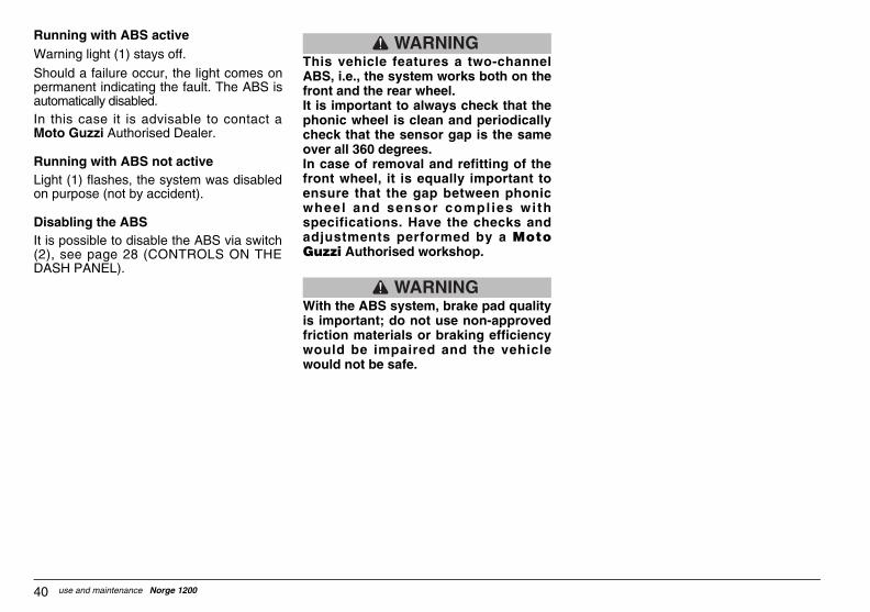
Running with ABS activeWarning light (1) stays off.
Should a failure occur, the light comes onpermanent indicating the fault. The ABS isautomatically disabled.In this case it is advisable to contact aMoto Guzzi Authorised Dealer.
Running with ABS not activeLight (1) flashes, the system was disabledon purpose (not by accident).
Disabling the ABSIt is possible to disable the ABS via switch(2), see page 28 (CONTROLS ON THEDASH PANEL).
WARNINGThis vehicle features a two-channelABS, i.e., the system works both on thefront and the rear wheel.It is important to always check that thephonic wheel is clean and periodicallycheck that the sensor gap is the sameover all 360 degrees.In case of removal and refitting of thefront wheel, it is equally important toensure that the gap between phonicwheel and sensor compl ies wi thspecifications. Have the checks andadjustments performed by a MotoGuzzi Authorised workshop.
WARNINGWith the ABS system, brake pad qualityis important; do not use non-approvedfriction materials or braking efficiencywould be impaired and the vehiclewould not be safe.

41use and maintenance Norge 1200
The clutch reservoir is located on the lefthandlebar, close to the clutch lever fitting.
NOTE Halve maintenance intervals ifyou are riding in rainy or dusty conditions,on rough road surfaces or when the vehicleis used in competitions.
Before leaving, check the fluid level in thereservoir, see page 42 (CLUTCH), have itchanged every two years by a Moto GuzziAuthorised Dealer.
WARNINGDo not ride if the clutch hydraulic circuitis leaking.
GUZum_norge1200#06_###e.book Page 41 Saturday, May 27, 2006 12:55 PM
CLUTCH FLUID - recommendations
NOTE This vehicle is fi tted with ahydraulically-controlled clutch.
CAUTIONAny sudden changes in p lay orhardness in the clutch lever are warningsigns of problems with the hydrauliccircuit.P lease contact a Moto GuzziAuthorised Dealer in case you have anydoubts on the operation of the systemand in case you are not able to carry outthe normal checks.
CAUTIONMake sure the clutch hose is not twistedor worn.
Prevent water or dust from accidentallygetting into the circuit.
Wear latex gloves when servicing thehydraulic circuit.
Clutch fluid is an irritant. Avoid contactwith eyes or skin.
In the event of accidental contact, flushaffected area thoroughly. Obtainmedical attention or, if fluid has beenspilled in the eyes, seek the assistanceof an ophthalmologist.
DO NOT RELEASE INTO THEENVIRONMENT.
KEEP AWAY FROM CHILDREN.
When handling clutch fluid, take carenot to spill it onto plastic or paint-finished parts or they will damage.
Have clutch fluid changed every twoyears by a Moto Guzzi AuthorisedDealer.
Use the fluid recommended in thelubr icants tab le , see page 99(LUBRICANT CHART).

CAUTIONnger: clutch fluid could leak out.ver operate the clutch lever when theservoir plug is loose or has been
oved.
WARNINGoid long exposure of clutch fluid to.utch fluid is hygroscopic and willsorb moisture from the air.ep the clutch fluid reservoir openST LONG ENOUGH to top up level.
CAUTIONce a cloth under the clutch reservoir
protect it from any fluid spillage.
Unscrew the two screws (2) of the clutchfluid reservoir (1) using a small cross-head screwdriver.
2
GUZum_norge1200#06_###e.book Page 42 Saturday, May 27, 2006 12:55 PM
use and maintenance Norge 120042
CLUTCH
NOTE Halve maintenance intervals ifyou are riding in rainy or dusty conditions,on rough road surfaces or when the vehicleis used in competitions.
Every 10000 km (6250 mi) have the clutchinspected by a Moto Guzzi AuthorisedDealer.
CHECKu Place the vehicle on the stand, see page
60 (PUTTING THE VEHICLE ON THESTAND).
u Turn the handlebar partially to the right,so that the f luid inside the clutchreservoir is parallel to the reservoir edge(1) (see figure).
u Make sure that the fluid level exceedsthe "MIN" mark.
u MIN= minimum levelu Top up if the fluid does not reach at least
the ≈MIN∆ mark.
TOPPING UP
Carefully read page 41 (CLUTCH FLUID- recommendations).
DaNererem
AvairClabKeJU
Plato
u
1
43use and maintenance Norge 1200
TYRESThis vehicle is equipped with tubelesstyres.
NOTE Halve maintenance intervals ifyou are riding in rainy or dusty conditions,on rough road surfaces or when the vehicleis used in competitions.
WARNINGCheck the inflation pressure at ambienttemperature every two weeks. Every 1000 km (625 mi) check tires forwear and check their inflating pressure atambient temperature, see page 96(TECHNICAL DATA).Measuring pressure on hot tyres will leadto inaccurate measurement.It is especially important to measure tyrepressure before and after a long trip.Over-inflated tyres will not absorb bumpswhen riding on rough road surfaces andresulting vibration is transferred throughthe handlebar, giving a hard ride andreducing tyre grip especially duringcornering. Conversely, under-inflation will put morestress on the sidewalls (1) and the tyremay slip on the rim or even come off therim, leading to loss of control.
GUZum_norge1200#06_###e.book Page 43 Saturday, May 27, 2006 12:55 PM
CAUTIONDo not rock the motorcycle from side toside when topping up or clutch fluid willspill out.Do not add any additives or otherproducts to the fluid.If you use a funnel or other tools, makesure that they are perfectly clean.
u Raise and remove the plug (3) togetherwith the screws (2).
u Remove the gasket (4).
NOTE As a reference to obtain ≈MAX∆level, top up until fluid completely coverssight glass (5), keep the clutch reservoirupright.
u Top up reservoir (1) using recommendedclutch fluid, see page 99 (LUBRICANTCHART), until reaching the correct level.
CAUTIONDo not exceed the "MAX" level mark.
u Fit back the gasket (4) in its seatcorrectly.
u Refit the cover (3).u Fit and tighten the screws (2).
WARNINGCheck the clutch for proper operation.If clutch lever free travel is too long or inthe event of clutch inefficiency, contacta Moto Guzzi Authorised Dealer, as thesystem may need bleeding.
2
5
3
4
1
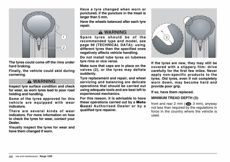
the tyres are new, they may still bevered with a slippery film: driverefully for the first few miles. Neverply non-specific products to thees. Old tyres, even if not completelyrn down, may become hard and
ovide poor grip.
o, have them replaced.
NIMUM TREAD DEPTH (3):
nt and rear 2 mm ( 3 mm), anywayt less than required by the regulations ince in the country where the vehicle ised.
USA
GUZum_norge1200#06_###e.book Page 44 Saturday, May 27, 2006 12:55 PM
use and maintenance Norge 120044
The tyres could come off the rims underhard braking. Finally, the vehicle could skid duringcornering.
WARNINGInspect tyre surface condition and checkfor wear, as worn tyres lead to poor roadholding and handling. Some of the tyres approved for thisvehicle are equipped with wearindicators. There are several kinds of wearindicators. For more information on howto check the tyres for wear, contact yourDealer. Visually inspect the tyres for wear andhave them changed if worn.
Have a tyre changed when worn orpunctured, if the puncture in the tread islarger than 5 mm.Have the wheels balanced after each tyrerepair.
WARNINGSpare tyres should be of therecommended type and model, seepage 96 (TECHNICAL DATA); usingdifferent tyres then the specified onesnegatively affects vehicle handling.Do not install tube tyres on tubelesstyre rims or vice versa.Make sure that caps are in place on thevalves (2), or the tyres may deflatesuddenly. Tyre replacement and repair, and wheelservicing and balancing are delicateoperations that should be carried outusing adequate tools and are best left toexperienced mechanics.For this reason, it is advisable to havethese operations carried out by a MotoGuzzi Authorised Dealer or by aqualified tyre repairer.
If cocaaptyrwopr
If s
MI
fronoforus
2

45use and maintenance Norge 1200
ADJUSTING THE FRONT BRAKE LEVER AND THE CLUTCH LEVERThe grab distance of the lever (1) [distancefrom the grip (2)] can be adjusted byrotating the adjuster (3).Positions ≈1∆ and ≈4∆ correspond to anapproximate lever-handgrip distancerespectively of 105 and 85 mm.Posit ions ≈2∆ and ≈3∆ correspond tointermediate distances.
u H Push the lever (1) forward and turn dial(3) until the required number matchesthe arrow.
3
2
1
1
2
3
4
GUZum_norge1200#06_###e.book Page 45 Saturday, May 27, 2006 12:55 PM
ENGINE OIL
WARNINGProlonged or repeated contact withengine oil may cause severe skindamage.
Wash your hands careful ly af terhandling engine oil.
KEEP AWAY FROM CHILDREN.
DO NOT DISPOSE OF OIL IN THEENVIRONMENT
Dispose of engine oil - stored in asealed container - through the nearestwaste oil reclamation firm or throughthe supplier.
Wear latex gloves during servicing.
CAUTIONIf the alarm light and the engine oilpressure icon “ ” on the LCD comeon during engine normal operation, itmeans that the engine oil pressure in thecircuit is low.If so, check engine oil level, see page 67(CHECKING AND TOPPING UP ENGINEOIL LEVEL), should it be incorrect,immediately stop the engine and contacta Moto Guzzi Authorised dealer.
CAUTIONProceed with care. Do not spill the oil!Take care not to smear any component,the area in which you are working andthe surrounding area. Carefully removeany trace of oil.In case of leakage or malfunction,contact a Moto Guzzi AuthorisedDealer.Periodically check the engine oil level, seepage 67 (CHECKING AND TOPPING UPENGINE OIL LEVEL).To change engine oi l , see page 63(SCHEDULED MAINTENANCE CHART)and page 68 (CHANGING ENGINE OILAND OIL FILTER).
NOTE Use high quality oil, see page 99(LUBRICANT CHART).

HAUST MUFFLER/EXHAUST LENCER
WARNINGmpering with the noise controlstem is prohibited.
ners are warned that the law mayhibit:
The removal or rendering inoperative byany person, other than for purposes ofmaintenance, repair or replacement, ofany dev ice or e lement o f des ignincorporated into any new vehicle - forthe purpose of noise control - prior to itssale or delivery to the end purchaser orwhile it is in use;The use of the vehicle after such deviceor element of design has been removedor rendered inoperative by any person.eck the exhaust muffler/silencer and the
encer pipes; make sure that they show traces of rust or holes and that thehaust system is operating properly.
the exhaust system becomes noisy,mediately contact your Moto Guzzithorised Dealer.
GUZum_norge1200#06_###e.book Page 46 Saturday, May 27, 2006 12:55 PM
use and maintenance Norge 120046
CATALYTIC SILENCER
WARNINGDo not park the vehicle close to driedbrushwood or in places where childrenare likely to come in contact with it,because the catalytic muffler reachesvery high operating temperature. Payutmost attention and avoid any contactuntil it has cooled down.
This vehicle fits a silencer with "platinum-palladium-rhodium" three-way metalcatalytic converter.
This device provides for the oxidation ofthe CO (carbon monoxide) and of the HC(unburned hydrocarbons) contained in theexhaust gases, changing them into carbondioxide and steam, respectively.
CAUTIONUse unleaded fuel only. Lead willdamage the catalytic converter.
EXSI
Tasy
Owpro√
√
Chsilnoex
If imAu
47use and maintenance Norge 1200
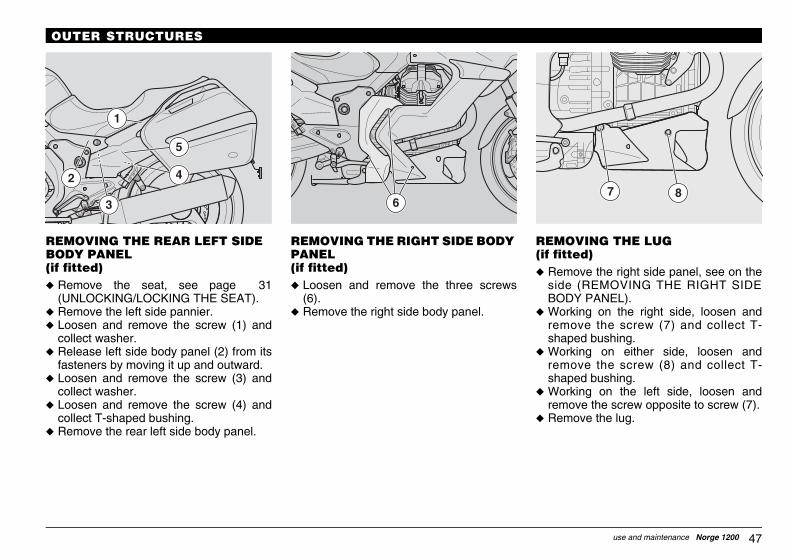
REMOVING THE LUG(if fitted)u Remove the right side panel, see on the
side (REMOVING THE RIGHT SIDEBODY PANEL).
u Working on the right side, loosen andremove the screw (7) and collect T-shaped bushing.
u Working on either side, loosen andremove the screw (8) and collect T-shaped bushing.
u Working on the left side, loosen andremove the screw opposite to screw (7).
u Remove the lug.
7 8
GUZum_norge1200#06_###e.book Page 47 Saturday, May 27, 2006 12:55 PM
OUTER STRUCTURES
REMOVING THE REAR LEFT SIDE BODY PANEL(if fitted)u Remove the seat, see page 31
(UNLOCKING/LOCKING THE SEAT).u Remove the left side pannier.u Loosen and remove the screw (1) and
collect washer.u Release left side body panel (2) from its
fasteners by moving it up and outward.u Loosen and remove the screw (3) and
collect washer.u Loosen and remove the screw (4) and
collect T-shaped bushing.u Remove the rear left side body panel.
REMOVING THE RIGHT SIDE BODY PANEL(if fitted)u Loosen and remove the three screws
(6).u Remove the right side body panel.
1
2
3
4
5
6
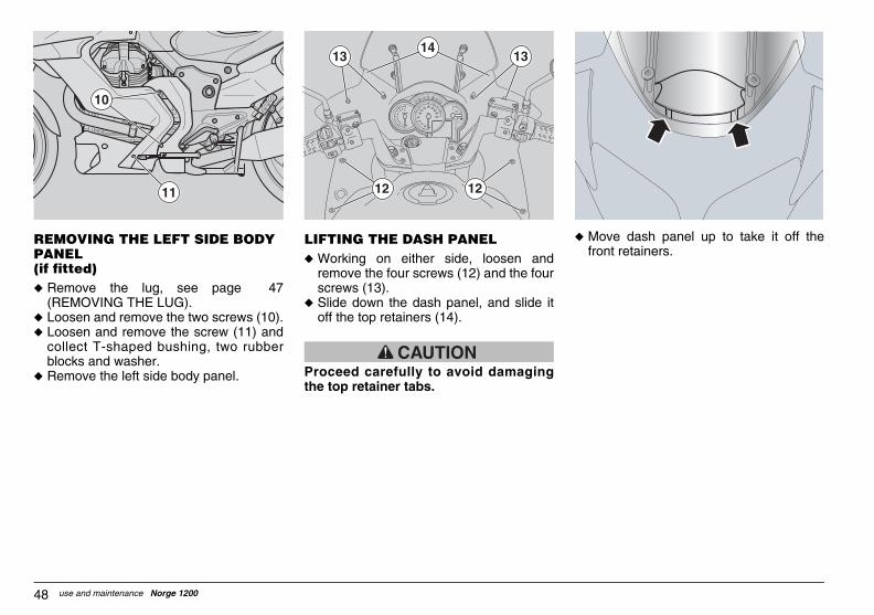
Move dash panel up to take it off thefront retainers.
GUZum_norge1200#06_###e.book Page 48 Saturday, May 27, 2006 12:55 PM
use and maintenance Norge 120048
REMOVING THE LEFT SIDE BODY PANEL(if fitted)u Remove the lug, see page 47
(REMOVING THE LUG).u Loosen and remove the two screws (10).u Loosen and remove the screw (11) and
collect T-shaped bushing, two rubberblocks and washer.
u Remove the left side body panel.
LIFTING THE DASH PANELu Working on either side, loosen and
remove the four screws (12) and the fourscrews (13).
u Slide down the dash panel, and slide itoff the top retainers (14).
CAUTIONProceed carefully to avoid damagingthe top retainer tabs.
u
11
10
12 12
13 1314

49use and maintenance Norge 1200
NOTE The rider must get on the vehiclefirst and get off last to ensure he/she hascontrol and balance of the vehicle while thepassenger is mounting or dismounting.
GUZum_norge1200#06_###e.book Page 49 Saturday, May 27, 2006 12:55 PM
INSTRUCTIONS FOR USE
GETTING ON AND OFF THE VEHICLEFollow the instructions below closely inorder to avoid injury to persons, damage toproperty and to the vehicle in the event therider or passenger falls off the vehicleand/or the vehicle falls or overturns.
WARNINGRisk of falling and overturning.Proceed with care.When getting on and off the vehicle, makesure nothing is restricting your movements;you should not be holding any objects inyour hands, such as helmet, gloves orglasses.Always get on and off the vehicle from theleft side and with the side stand down.
CAUTIONDo not apply the load of your weight orof the passenger’s weight onto the sidestand.
The stand has been designed to supportthe weight of the vehicle and a minimalload, without the added weight of riderand/or passenger.The purpose of the side stand is to preventthe vehicle from falling or overturning whilerider and passenger get on the vehicle andthe stand should not be used to support theweight of rider and passenger.
While getting on and off, the vehicle maybecome unstable due to its weight, and thevehicle may fall or overturn.

WARNINGke sure the ground is firm and leveld free from obstacles.With the left shoe heel, extend the sidestand completely.
OTE If you can not reach the groundth both feet when sitting astride thehicle, place your right foot on the groundyou lose balance, the side stand willvent a fall on the left side) and be readyput your left foot to the ground to helpep your balance.Place both feet on the ground andbalance the vehicle keeping it upright.Instruct the passenger on how to safelyget off the vehicle.
WARNINGsk of falling and overturning.ke sure that the passenger hasmounted. not rest your weight on the sidend.
Lean the vehicle to the side until thestand is resting on the ground.Keep your hands firmly on the handlebarand get off the vehicle.Turn the handlebar fully to the left.Fold up the passenger footpegs.
CAUTIONke sure that the vehicle is stable.
GUZum_norge1200#06_###e.book Page 50 Saturday, May 27, 2006 12:55 PM
use and maintenance Norge 120050
When getting on and off the vehicle, thepassenger must move carefully to avoidcausing imbalance.
NOTE The rider must instruct thepassenger on how to safely get on and offthe vehicle.The vehicle is equipped with passengerfoo tpegs to make mount ing anddismounting easier. The passenger mustalways use the left footpeg to get on andoff the vehicle. Never get off or attempt to get off thevehicle by jumping or stretch your leg toput your foot on the ground to dismount.These are incorrect procedures that willaffect the stability and balance of thevehicle.
NOTE Any bags or objects strapped tothe rear of the vehicle can represent anobstacle while getting on and off.
Swing your right leg over the seat in acontrolled movement so as not to hit thetail section or luggage at the rear and avoidresulting imbalance.
GETTING ON THE VEHICLEu Grasp the handlebar correctly and get
on the vehicle without resting yourweight on the side stand.
NOTE If you can not reach the groundwith both feet when sitting astride thevehicle, place your right foot on the ground(if you lose balance, the side stand willprevent a fall on the left side) and be readyto put your left foot to the ground to helpkeep your balance.
u Place both feet on the ground, straightenthe vehicle and make sure to balance itfully.
NOTE The rider must not fold out orattempt to fold out the passenger footpegwhile seated astride the vehicle, becausethis might compromise the stability andbalance of the vehicle.
u Ask your passenger to fold out bothpassenger footpegs.
u Instruct the passenger on how to safelyget on the vehicle.
u Pull the side stand fully up using your leftfoot.
GETTING OFF THE VEHICLEu Select an appropriate location for
parking, see page 59 (PARKING).u Stop the vehicle, see page 59
(STOPPING).
Maanu
Nwive(if preto keu
u
RiMadisDostau
u
u
u
Ma

51use and maintenance Norge 1200
CAUTIONAfter the first 1000 km (625 mi) andevery 10000 km (6250 mi) thereafter, theright display will show icon " ".
In this case, have a Moto GuzziAuthorised Dealer perform all serviceoperat ions as indica ted in thescheduled maintenance chart, see page63 (SCHEDULED MAINTENANCECHART).
1
GUZum_norge1200#06_###e.book Page 51 Saturday, May 27, 2006 12:55 PM
PRE-RIDE CHECKS
WARNINGBefore starting, always perform vehiclepre- r ide checks, to ensure sa feoperation, see page 52 (PRE-RIDECHECKS CHART).
Failure to perform these checks maylead to severe personal injury or vehicledamage.
Do not hesitate to contact your Moto GuzziAuthorised Dealer if you need clarificationsabout the operation of vehicle controls or ifyou suspec t o r have iden t i f i ed amalfunction.A quick pre-ride check takes just a fewminutes and greatly improves your safety.
NOTE This vehicle is equipped with anelectronic engine control unit capable ofdetecting abnormal operation in real timeand storing faults.
Any time the ignition switch is set to ≈ ∆,the alarm LED ≈ ∆ (1) on the instrumentpanel comes on for three seconds.
CAUTIONIf the alarm LED “ ” (1) and the “ SERVICE” diagnosis icon come onduring engine normal operation, itmeans that the contro l un i t hasdetected a failure. In most cases, theengine will keep running, althoughgiving less performance. Immediatelycontact a Moto Guzzi AuthorisedDealer.
!
!!

page
leaks. 35, 36, 37, 38, 76
all positions of the steering. 77
45, 67
43
-
-
oseness. -
st ensure full retraction. 79, 84
equired. -
34
27
bulbs or repair if faulty. 89, 90
. 7139 (ABS)
GUZum_norge1200#06_###e.book Page 52 Saturday, May 27, 2006 12:55 PM
use and maintenance Norge 120052
PRE-RIDE CHECKS CHART
Part Check
Front and rear disc brakes Check for proper operation, check lever free play, fluid level and check forCheck the pads for wear. If necessary, top up the fluid reservoirs.
Throttle Check for smooth operation; throttle should snap fully open and closed atAdjust and/or lubricate as required.
Engine oil Check and/or top up as required.
Wheels / tyres Check tyre surface, inflation pressure. Check for wear or damage.Remove any objects trapped in the tread.
Brake levers Make sure that they work smoothly.Lubricate the joints if necessary (rear brake control).
Clutch Check clutch operation, free travel of control lever (free play with a cold engine must be less than 1 mm).The clutch must not jerk and/or slip when operated.
Steering Steering should rotate smoothly and evenly. There should be no play or lo
Side standCentre stand
Check its operation. No friction during up and down movement, springs muLubricate joints and connections, if necessary.Check stand switch for proper operation.
Fastening elements Make sure that the fastening elements are not loose. Adjust or tighten as r
Fuel tank Check fuel level and top up, if necessary. Check the circuit for leaks. Make sure the filler plug is tightened securely.
Engine stop switch ( - ) Make sure that it operates correctly.
Lights, warning lights, horn,rear brake light switches andelectrical devices
Check the proper operation of the acoustic and visual devices. Change the
Transmission fluid Check. If level needs topping up, contact a Moto Guzzi Authorised DealerPhonic wheels Ensure that the phonic wheels are perfectly clean

53use and maintenance Norge 1200
u Make sure that the dimmer switch (1) isin position " ".
u Set the engine stop switch (2) to position" ".
u Turn the key (4) and set the ignitionswitch to position " ".
The following occurs:√ the parking lights come on;√ all warning lights on the instrument panel
come on;√ the LCD will show "Moto Guzzi" wording
for 2 seconds;√ the speed indicator and fuel gauge
indexes reach end of scale, rpm indexmoves to max. set value;
√ as soon as the first check routine is over,the warning lights go off, the instrumentsindicate the current value and the LCDdisplays the configuration set on theselector;
√ the fuel pump puts the feed circuit underpressure and hums for approximatelythree seconds.
CAUTIONIf the low fuel warning light " " (5) onthe instrument panel comes on, itmeans that there are 4 litres of fuel leftin the tank. Refuel as soon as possible,see page 34 (FUEL).
GUZum_norge1200#06_###e.book Page 53 Saturday, May 27, 2006 12:55 PM
STARTING
WARNINGThis is a high-performance vehicle. Werecommend that you become familiarwith it gradually using the greatest care.
Do not store any objects on the insideof the headlight fairing (between thehandlebar and the instrument panel) asthis could impair handlebar movementor hide the instrument panel from yourvision.
NOTE Before start ing the engine,carefully read section "Safe Riding", seepage 5 (SAFE RIDING).
WARNINGExhaust gases conta in carbonmonoxide, which is extremely toxic ifinhaled.
Do not start the engine in an enclosedspace or poorly ventilated area.
Failure to observe this warning maylead to loss of consciousness or evendeath by asphyxia.
NOTE With the side stand down, theengine can be started only if the gear is inneutral; if you attempt to engage a gearwith the stand down, the engine will stop.
With the side stand up, you can start theengine in neutral or with a gear engagedand the clutch lever pulled in.u Sit astride the vehicle, see page 49
(GETTING ON AND OFF THEVEHICLE).
u Make sure the stand is fully up.
4
2
1
3
5

ARTING THE ENGINE FROM COLDe vehicle is fitted with an automatic coldrt device and does not require anycaution for cold starting.case of low ambient temperature (closeor lower than 0 °C / 32 °F), the automaticld start switches on and increases them unt i l reaching opt imum enginempera tu re and sw i tches o f ftomatically.
CAUTIONe automatic cold start can not benually operated.
GUZum_norge1200#06_###e.book Page 54 Saturday, May 27, 2006 12:55 PM
use and maintenance Norge 120054
u Completely pull the front brake lever.u Completely pull the clutch lever (6) and
set the gear shift lever (7) to neutral[green LED ≈ ∆ on].
NOTE Hold the c lu tch lever (6 )completely pulled until the engine starts.
NOTE In case o f low ambien ttemperature (close to or lower than 0 °C √32 °F), see page 54 (STARTING THEENGINE FROM COLD).
u Press the starter button ≈ ∆ (3), do notaccelerate, and immediately release it,the control unit will manage the startingprocedure on its own.
√ The low beam comes on.
CAUTIONIf the alarm light “ ” and the engine oilpressure icon “ ” are still on, or comeon during engine normal operation, itmeans that the oil pressure in thecircuit is low.
u Keep at least one brake operated and donot accelerate until you are ready tomove off.
CAUTIONNever move off abruptly with a coldengine.To reduce emiss ions and fue lconsumption, ride slowly until coveringseveral miles to warm the engine up tooperating temperature.
CAUTIONIf the alarm LED “ ” and the “ SERVICE” diagnosis icon come onduring engine normal operation, itmeans that the contro l un i t hasdetected a failure. In most cases, theengine will keep running, althoughgiving less performance. Immediatelycontact a Moto Guzzi AuthorisedDealer.
STThstapreIn to corpteau
Thma
7
6
!
!!
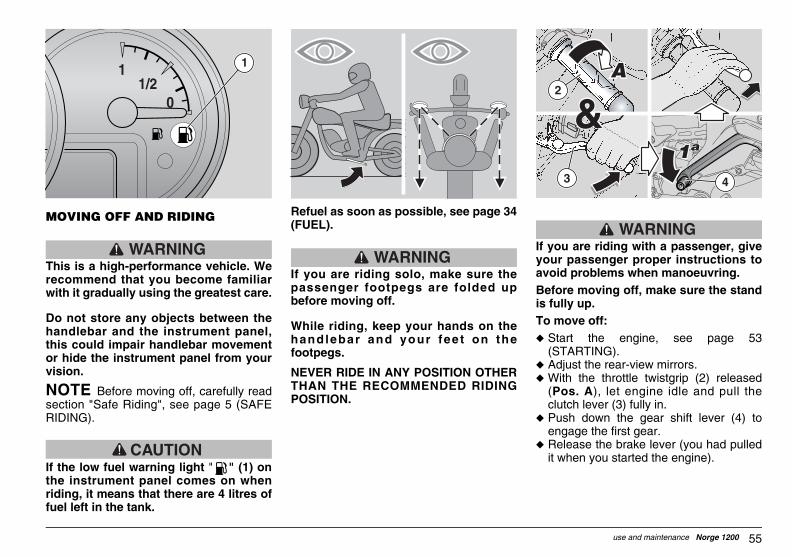
55use and maintenance Norge 1200
WARNINGIf you are riding with a passenger, giveyour passenger proper instructions toavoid problems when manoeuvring.Before moving off, make sure the standis fully up.To move off: u Start the engine, see page 53
(STARTING).u Adjust the rear-view mirrors.u With the throttle twistgrip (2) released
(Pos. A), let engine idle and pull theclutch lever (3) fully in.
u Push down the gear shift lever (4) toengage the first gear.
u Release the brake lever (you had pulledit when you started the engine).
2
3 4
GUZum_norge1200#06_###e.book Page 55 Saturday, May 27, 2006 12:55 PM
MOVING OFF AND RIDING
WARNINGThis is a high-performance vehicle. Werecommend that you become familiarwith it gradually using the greatest care.
Do not store any objects between thehandlebar and the instrument panel,this could impair handlebar movementor hide the instrument panel from yourvision.
NOTE Before moving off, carefully readsection "Safe Riding", see page 5 (SAFERIDING).
CAUTIONIf the low fuel warning light " " (1) onthe instrument panel comes on whenriding, it means that there are 4 litres offuel left in the tank.
Refuel as soon as possible, see page 34(FUEL).
WARNINGIf you are riding solo, make sure thepassenger footpegs are folded upbefore moving off.
While riding, keep your hands on thehandlebar and your fee t on thefootpegs.
NEVER RIDE IN ANY POSITION OTHERTHAN THE RECOMMENDED RIDINGPOSITION.
1
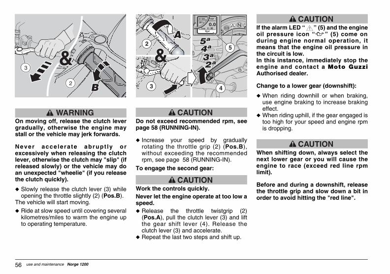
CAUTIONhe alarm LED “ ” (5) and the enginel pressure icon “ ” (5) come onring engine normal operation, itans that the engine oil pressure in
e circuit is low.this instance, immediately stop thegine and contact a Moto Guzzithorised dealer.
ange to a lower gear (downshift):
When riding downhill or when braking,use engine braking to increase brakingeffect.When riding uphill, if the gear engaged istoo high for your speed and engine rpmis dropping.
CAUTIONhen shifting down, always select thext lower gear or you will cause thegine to race (exceed red line rpmit).
fore and during a downshift, releasee throttle grip and slow down a bit inder to avoid hitting the "red line".
!
GUZum_norge1200#06_###e.book Page 56 Saturday, May 27, 2006 12:55 PM
use and maintenance Norge 120056
WARNINGOn moving off, release the clutch levergradually, otherwise the engine maystall or the vehicle may jerk forwards.
Never acce lerate abrupt ly orexcessively when releasing the clutchlever, otherwise the clutch may "slip" (ifreleased slowly) or the vehicle may doan unexpected "wheelie" (if you releasethe clutch quickly).
u Slowly release the clutch lever (3) whileopening the throttle slightly (2) (Pos.B).
The vehicle will start moving.u Ride at slow speed until covering several
kilometres/miles to warm the engine upto operating temperature.
CAUTIONDo not exceed recommended rpm, seepage 58 (RUNNING-IN).
u Increase your speed by graduallyrotating the throttle grip (2) (Pos.B),without exceeding the recommendedrpm, see page 58 (RUNNING-IN).
To engage the second gear:
CAUTIONWork the controls quickly.Never let the engine operate at too low aspeed.u Release the throttle twistgrip (2)
(Pos.A), pull the clutch lever (3) and liftthe gear shift lever (4). Release theclutch lever (3) and accelerate.
u Repeat the last two steps and shift up.
If toidumethIn enAu
Ch
u
u
Wneenlim
Bethor
2
3 4
5
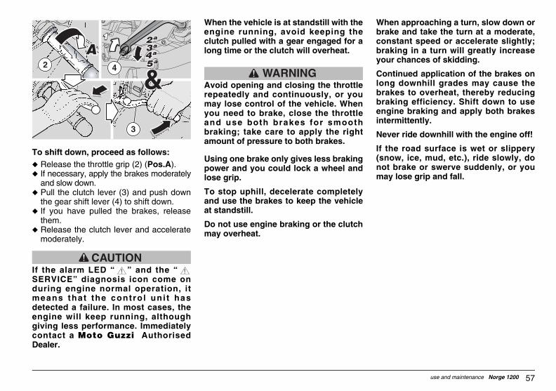
57use and maintenance Norge 1200
When approaching a turn, slow down orbrake and take the turn at a moderate,constant speed or accelerate slightly;braking in a turn will greatly increaseyour chances of skidding.
Continued application of the brakes onlong downhill grades may cause thebrakes to overheat, thereby reducingbraking efficiency. Shift down to useengine braking and apply both brakesintermittently.
Never ride downhill with the engine off!
If the road surface is wet or slippery(snow, ice, mud, etc.), ride slowly, donot brake or swerve suddenly, or youmay lose grip and fall.
GUZum_norge1200#06_###e.book Page 57 Saturday, May 27, 2006 12:55 PM
To shift down, proceed as follows:u Release the throttle grip (2) (Pos.A).u If necessary, apply the brakes moderately
and slow down.u Pull the clutch lever (3) and push down
the gear shift lever (4) to shift down.u If you have pulled the brakes, release
them.u Release the clutch lever and accelerate
moderately.
CAUTIONIf the alarm LED “ ” and the “SERVICE” diagnosis icon come onduring engine normal operation, itmeans that the contro l un i t hasdetected a failure. In most cases, theengine will keep running, althoughgiving less performance. Immediatelycontact a Moto Guzzi AuthorisedDealer.
When the vehicle is at standstill with theengine running, avoid keeping theclutch pulled with a gear engaged for along time or the clutch will overheat.
WARNINGAvoid opening and closing the throttlerepeatedly and continuously, or youmay lose control of the vehicle. Whenyou need to brake, close the throttleand use both brakes for smoothbraking; take care to apply the rightamount of pressure to both brakes.
Using one brake only gives less brakingpower and you could lock a wheel andlose grip.
To stop uphill, decelerate completelyand use the brakes to keep the vehicleat standstill.
Do not use engine braking or the clutchmay overheat.
2
3
4
! !

WARNINGter the first 1000 km (625 mi), have aoto Guzzi Authorised dealer carry out "Post running-in" checks specified in periodic maintenance chart, see page
(SCHEDULED MAINTENANCE CHART).ilure to perform these checks may leadinjury to yourself or other people and/orhicle damage.
After the first 1000 km (625 mi) and until2000 km (1250 mi), ride more briskly,varying speed and using maximumacceleration for just a few seconds, this is toensure better coupling of the components;never exceed 6000 rpm (see table).After the first 2000 km (1250 mi) you mayrun the engine harder, however, withoutexceeding the maximum rpm allowed(7600 rpm).
ecommended maximum engine rpm
istance covered km (mi)
rpm
0 √ 1000 (0 √ 625) 5000
00 √ 2000 (625 √ 1250) 6000
over 2000 (1250) 7600
GUZum_norge1200#06_###e.book Page 58 Saturday, May 27, 2006 12:55 PM
use and maintenance Norge 120058
WARNINGWatch out for obstacles or suddenchanges in the road surface.
Rough roads, rails, manhole covers,road markings, large steel plates nearroadwork become slippery in the wetand should be avoided or negotiatedwith the greatest care, riding carefullyand keeping the vehicle upright.
Signal your intention to change lane orturn in good t ime using the turnindicators and avoid sudden swervingor movements.
Switch off the turn indicators as soonas you have finished turning.
Be extremely careful when overtakingor being overtaken.
When riding in the rain, the spraythrown up by the tyres of large vehicleswill reduce your vision; the air wavecreated by a large vehicle may makeyou lose control of the vehicle.
RUNNING-INCorrect engine running-is essential toensuring proper performance and durability.
Twisty, hilly roads are ideal for an effectiverunning-in of engine, suspension and brakes.
Vary speed frequently during the running-inperiod.This will allow engine parts to be alternatelyloaded and unloaded, allowing them to cooldown when unloaded.
NOTE It is possible that during the firstperiod of use the clutch slightly smells as ifsomething was burnt inside. This condition isnormal and will stop as soon as clutch platesrun in.
While it is important to put some stress onengine components during running-in, it isequally important to avoid extreme loadconditions.
NOTE From 2000 km (1250 mi) onward,the engine is ready to provide topperformance.
Follow these recommendations:u Do not flip the throttle open abruptly with the
engine running at low rpm - either during orafter the running-in period.
u Until you have covered the first 100 km (62mi), use the brakes gently and avoid harsh,prolonged braking. This will help the brakepads bed in properly against the brakediscs.
u During the first 1000 km (625 mi) neverexceed 5000 rpm.
AfMthethe63Fato ve
u
u
R
D
10

59use and maintenance Norge 1200
To park the vehicle:u Select a suitable area for parking.u Stop the vehicle, see in this page
(STOPPING).u Set the engine stop switch (3) to position
" ".u Turn the key (4) and set the ignition switch
(5) to position " ".
WARNINGCarefully follow the indications forgetting on and off the vehicle, see page49 (GETTING ON AND OFF THEVEHICLE).u Following the instructions, direct your
passenger (if you are carrying one) todismount and then get off.
u Lock the steering, see page 29(STEERING LOCK) and remove the key(4).
WARNINGMake sure that the vehicle is stable.
3
4
5
GUZum_norge1200#06_###e.book Page 59 Saturday, May 27, 2006 12:55 PM
STOPPING
WARNINGIf you can, do not stop or slow downsuddenly and avoid limit-braking.
u Release the throttle grip (1) (pos. A) andgradually put on the brakes and shiftdown the gears at the same time to slowdown, see page 55 (MOVING OFF ANDRIDING).
When you have slowed down, beforethe vehicle comes to a stop:u Pull the clutch lever (2) to prevent the
engine stalling.When the vehicle has come to a stop:
u Select neutral (green warning light " "on).
u Release the clutch lever (2).u If you need to stop only briefly, keep at
least one brake applied.
PARKINGIt is very important to select an adequate toplace to park your vehicle - observe localregulations and the indications givenbelow.
WARNINGPark the vehicle on firm and levelground to prevent it from falling.
Do not lean the vehicle against a wall, orlay it on the ground.
Make sure that the vehicle and any of itsparts that are still hot do not pose aburn risk for any persons nearby,especially children. Do not leave thevehicle unattended when the engine ison or the key is inserted into theignition switch.
WARNINGThe fall or excessive inclination of thevehicle may cause the fuel to flow out ofthe tank.
The fuel used in internal combustionengines is highly flammable and canbecome explosive under particularconditions.
CAUTIONDo not apply the load of your weight orof the passenger’s weight onto the sidestand.

NTRE STAND
WARNINGs forbidden to position the vehicle one centre stand when sitting astride thehicle.
WARNINGke sure the ground is firm and leveld free from obstacles.
Select an appropriate location forparking, see page 59 (PARKING).Grab the left handgrip (1) and handle (4).
CAUTIONr your safety, the side stand downndition is indicated to avoid vehicleping over.
4
5
GUZum_norge1200#06_###e.book Page 60 Saturday, May 27, 2006 12:55 PM
use and maintenance Norge 120060
PUTTING THE VEHICLE ON THE STAND
SIDE STANDTo put the vehicle on the side stand whileseated astride the vehicle, see page 49(GETTING ON AND OFF THE VEHICLE).
If you have folded up the stand (say, towheel the vehicle forward or backward),put the vehicle back on the stand asfollows:
WARNINGMake sure the ground is firm and leveland free from obstacles.
u Select an appropriate location forparking, see page 59 (PARKING).
u Grasp the left grip (1) and place yourright hand on the rear upper part of thevehicle (2).
u Push on the side stand with your rightfoot and lower it completely (3).
u Lean the vehicle to the side until thestand is resting on the ground.
u Rotate the handlebar fully to the left.
WARNINGMake sure that the vehicle is stable.
CE
It ithve
Maan
u
u
Focotip
2
3
1
1

61use and maintenance Norge 1200
GUZum_norge1200#06_###e.book Page 61 Saturday, May 27, 2006 12:55 PM
NOTE Do not rest the side stand toground. Keep the vehicle upright.
u Push down the side stand (5) with yourright foot and extend it completely.
u Push onto centre stand lever (6) (Pos.A) and rest it onto the ground.
CAUTIONProceed with care.The positioning of the vehicle on thecentre stand may be difficult, since thevehicle is very heavy. Release thehandgrip (1) and handle (4) only whenthe vehicle is steady on the stand.
u Load your weight onto the centre standlever (6) (Pos. B) and move your centreof gravity to the back of the vehicle(Pos.C).
WARNINGMake sure that the vehicle is stable.
u Fold up the side stand.
6
AA AA
6BB
BB
CC
4
1

r periodic maintenance, servicing orhnical advice, contact a Moto Guzzithorised Dealer, who will ensure prompt,curate service.k your Moto Guzzi Authorised Dealer torry out a road test after a repair oreduled maintenance operation.
addition, perform the "Pre-ride checks"er each maintenance operation, seege 52 (PRE-RIDE CHECKS CHART).
TE This vehicle is equipped with anctronic engine control unit capable oftecting abnormal operation in real timed storing faults.y time the ignition switch is set to ≈ ∆, light “ ” on the instrument panel
mes on for three seconds.
CAUTIONthe alarm LED “ ” and the “RVICE” diagnosis icon come onring engine normal operation, itans that the control unit has detectedailure. In most cases, the engine willep running, although giving lessrformance. Immediately contact ato Guzzi Authorised Dealer.
!
! !
GUZum_norge1200#06_###e.book Page 62 Saturday, May 27, 2006 12:55 PM
use and maintenance Norge 120062
SUGGESTIONS TO PREVENT THEFTNEVER leave the key in the ignition switchand always use the steering lock.Park the vehicle in a safe place, possibly ina garage or a protected place.
When possible, use an additional antitheftdevice.
Make sure you have all the necessarydocuments with you and that the excise taxhas been paid.
Write your personal data and telephonenumber in this page to help trace thevehicle back to you in the event it is stolenand subsequently recovered.
SURNAME: ...............................................
NAME: .......................................................
ADDRESS: ................................................
..................................................................
TELEPHONE NO.: ....................................
NOTE Recovered vehicles are oftentraced back to the owner thanks to his/herdetails recorded in the Owner's Manual.
MAINTENANCE
WARNINGFire hazard.Keep fue l and other f lammablesubstances away f rom e lect r iccomponents.Before proceeding to service or inspectof the vehicle, stop the engine andremove the key from the ignition, waitfor the engine and the exhaust systemto cool down and, if possible, lift theveh ic le us ing adequate l i f t ingequipment placed on firm and levelground.Ensure the area is well ventilated beforeproceeding. Be careful not to touch hot engine andexhaust system parts that might burnyou. Do not put any vehicle parts into yourmouth: vehicle components are notedible and some of them are harmful oreven toxic.
CAUTIONUnless expressly indicated otherwise,reassembly is a reversa l o f thedisassembly procedure.Wear latex gloves during servicing.Normally, scheduled maintenance can becarried out by the owner, although someoperations may require specific tools andtechnical training.
FotecAuacAscaschIn aftpa
NOeledeanAntheco
If SEdumea fkepeMo
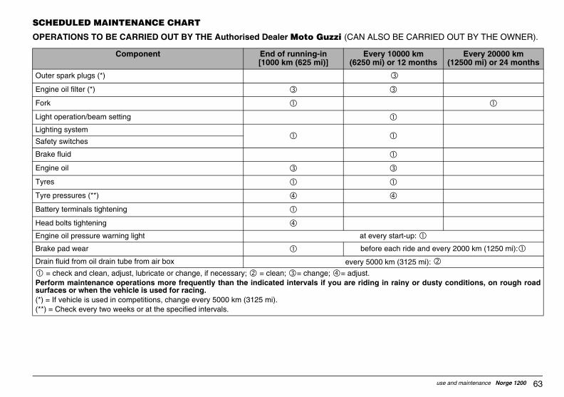
63use and maintenance Norge 1200
O BE CARRIED OUT BY THE OWNER).
y 10000 km i) or 12 months
Every 20000 km (12500 mi) or 24 months
ry start-up:
each ride and every 2000 km (1250 mi):
km (3125 mi):
in rainy or dusty conditions, on rough road
GUZum_norge1200#06_###e.book Page 63 Saturday, May 27, 2006 12:55 PM
SCHEDULED MAINTENANCE CHART
OPERATIONS TO BE CARRIED OUT BY THE Authorised Dealer Moto Guzzi (CAN ALS
Component End of running-in[1000 km (625 mi)]
Ever(6250 m
Outer spark plugs (*)
Engine oil filter (*)
Fork
Light operation/beam setting
Lighting system
Safety switches
Brake fluid
Engine oil
Tyres
Tyre pressures (**)
Battery terminals tightening
Head bolts tightening
Engine oil pressure warning light at eve
Brake pad wear before
Drain fluid from oil drain tube from air box every 5000
= check and clean, adjust, lubricate or change, if necessary; = clean; = change; = adjust.Perform maintenance operations more frequently than the indicated intervals if you are ridingsurfaces or when the vehicle is used for racing.(*) = If vehicle is used in competitions, change every 5000 km (3125 mi).(**) = Check every two weeks or at the specified intervals.

0000 km r 12 months
Every 20000 km (12500 mi) or 24 months
d then every 20000 km (12500 mi):
d then every 20000 km (12500 mi):
0 mi: - if worn:
= clean; = change; = adjust.r when the vehicle is used for racing.
GUZum_norge1200#06_###e.book Page 64 Saturday, May 27, 2006 12:55 PM
use and maintenance Norge 120064
OPERATIONS TO BE CARRIED OUT BY THE Moto Guzzi Authorised Dealer.
Component End of running-in[1000 km (625 mi)]
Every 1(6250 mi) o
Gearbox fluid
Idle mixture (CO)
Bowden cables and controls
Steering bearings and steering play
Wheel bearings
Brake discs
Air filter
Vehicle operation
Brake systems
Brake fluid
Fork fluid after the first 10000 km (6250 mi) an
Fork oil seals after the first 30000 km (18750 mi) an
Brake pads every 2000 km/125
Valve clearance adjustment
Wheels / tyres
Nut, bolt, screw tightening
Battery terminals tightening
Cylinder synchronisation
Suspensions and trim
= check and clean, adjust, lubricate or change, if necessary (as specified in the Workshop Manual); Halve maintenance intervals if you are riding in rainy or dusty conditions, on rough road surfaces o(*) = If vehicle is used for racing, check every 5000 km (3125 mi).

65use and maintenance Norge 1200
every 4 years:
every 4 years:
: , every 50000 km (31250 mi):
y 10000 km i) or 12 months
Every 20000 km (12500 mi) or 24 months
= clean; = change; = adjust.s or when the vehicle is used for racing.
GUZum_norge1200#06_###e.book Page 65 Saturday, May 27, 2006 12:55 PM
Final transmission fluid
Fuel pipes
Brake lines
Clutch wear (*)
Inner spark plugs
Generator belt every 20000 km (12500 mi)
Head stud bolts tightening
Exhaust pipe flange bolts
Component End of running-in[1000 km (625 mi)]
Ever(6250 m
= check and clean, adjust, lubricate or change, if necessary (as specified in the Workshop Manual); Halve maintenance intervals if you are riding in rainy or dusty conditions, on rough road surface(*) = If vehicle is used for racing, check every 5000 km (3125 mi).

WARNINGfore removing a clamp, determineether removal may lead to leakaged, if so, take adequate measures toevent leakage and protect themponents positioned near the joint.
REW CLAMPSr removal and installation it is sufficientuse a common screwdriver.
CAUTIONeck the conditions of the clamp andecessary replace it with a new one of
e same type and d imensions,ailable on request from Moto Guzzithorised Dealers.
hen tightening the clamp, make sureat the joint is sufficiently stable.
GUZum_norge1200#06_###e.book Page 66 Saturday, May 27, 2006 12:55 PM
use and maintenance Norge 120066
IDENTIFICATION DATAIt is a good rule to report the frame andengine numbers in the space provided inthis manual.
The frame number must be quoted whenpurchasing spare parts.
NOTE Altering a vehicle identificationnumbers is illegal and punished by the lawwith fines and imprisonment. In addition,altering the frame number invalidates thewarranty.
FRAME NUMBERThe frame number (1) is stamped on theright side of the steering tube.
Frame no. _________________________
ENGINE NUMBERThe engine number (2) is stamped on theleft side close to the oil level plug/dipstick.
Engine no. ________________________
JOINTS WITH SCREW CLAMPS
CAUTIONRemove ONLY the clamps indicated inthe maintenance procedures.
This text is not to be intended as anauthorisation to arbitrarily remove theclamps present on the vehicle.
Bewhanprco
SCFoto
Chif nthavAu
Wth
1 2
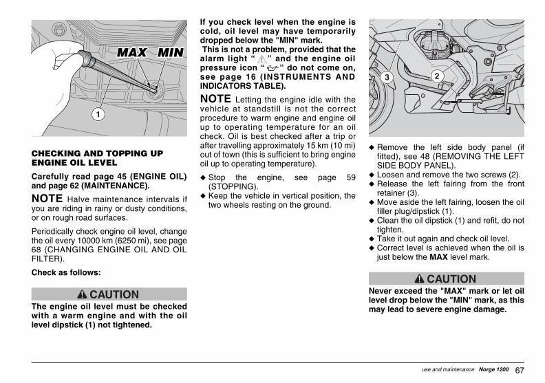
67use and maintenance Norge 1200
u Remove the left side body panel (iffitted), see 48 (REMOVING THE LEFTSIDE BODY PANEL).
u Loosen and remove the two screws (2).u Release the left fairing from the front
retainer (3).u Move aside the left fairing, loosen the oil
filler plug/dipstick (1).u Clean the oil dipstick (1) and refit, do not
tighten.u Take it out again and check oil level.u Correct level is achieved when the oil is
just below the MAX level mark.
CAUTIONNever exceed the "MAX" mark or let oillevel drop below the "MIN" mark, as thismay lead to severe engine damage.
23
GUZum_norge1200#06_###e.book Page 67 Saturday, May 27, 2006 12:55 PM
CHECKING AND TOPPING UP ENGINE OIL LEVEL
Carefully read page 45 (ENGINE OIL)and page 62 (MAINTENANCE).
NOTE Halve maintenance intervals ifyou are riding in rainy or dusty conditions,or on rough road surfaces.
Periodically check engine oil level, changethe oil every 10000 km (6250 mi), see page68 (CHANGING ENGINE OIL AND OILFILTER).
Check as follows:
CAUTIONThe engine oil level must be checkedwith a warm engine and with the oillevel dipstick (1) not tightened.
If you check level when the engine iscold, oil level may have temporarilydropped below the "MIN" mark. This is not a problem, provided that thealarm light “ ” and the engine oilpressure icon “ ” do not come on,see page 16 (INSTRUMENTS ANDINDICATORS TABLE).
NOTE Letting the engine idle with thevehicle at standstill is not the correctprocedure to warm engine and engine oilup to operating temperature for an oilcheck. Oil is best checked after a trip orafter travelling approximately 15 km (10 mi)out of town (this is sufficient to bring engineoil up to operating temperature).
u Stop the engine, see page 59(STOPPING).
u Keep the vehicle in vertical position, thetwo wheels resting on the ground.
1
!

CAUTIONl becomes very hot when engine isrmed up; beware of scalds during the
ocedure described below.
Place a container with more than 4000cu. cm. capacity under the drain plug (1).Unscrew and remove the drain plug (1).Remove the lower lug, see 47(REMOVING THE LUG).Unscrew and remove the filler plug (2).Drain the oil into the container; allowseveral minutes for oil to drain outcompletely.Check the sealing washers of the drainplug (1) and replace them if needed.Remove any metal debris collected bythe drain plug (1) magnet.Tighten the drain plug (1).
ain plugs (1) tightening torque: 12 Nm2 kgm).
1
GUZum_norge1200#06_###e.book Page 68 Saturday, May 27, 2006 12:55 PM
use and maintenance Norge 120068
If necessary, top up engine oil level asfollows:
u Unscrew and remove the filler plug (3).
CAUTIONDo not add any additives or otherproducts to the oil.
If you use a funnel or other tools, makesure that they are perfectly clean.
NOTE Use high-quality 10W - 60 oil, seepage 99 (LUBRICANT CHART).
Top up to correct level, see page 99(LUBRICANT CHART).
CHANGING ENGINE OIL AND OIL FILTER
CAUTIONChanging engine oil and engine oil filtercan prove difficult; these operations arebest left to experienced mechanics.
If necessary, contact your Moto GuzziAuthorised Dealer.
If you wish to perform these operationsyourself, follow these instructions.
Carefully read page 45 (ENGINE OIL)and page 62 (MAINTENANCE).
NOTE Halve maintenance intervals ifyou are riding in rainy or dusty conditions,on rough road surfaces or when the vehicleis used in competitions.
Periodically check engine oil level, changethe oil every 10000 km (6250 mi), see page67 (CHECKING AND TOPPING UPENGINE OIL LEVEL).
To change oil:
NOTE Warm oil is more fluid and willdrain out more easily and completely; idealtemperature is reached after engine hasbeen running for about 20 minutes.
Oiwapr
u
u
u
u
u
u
u
u
Dr(1.
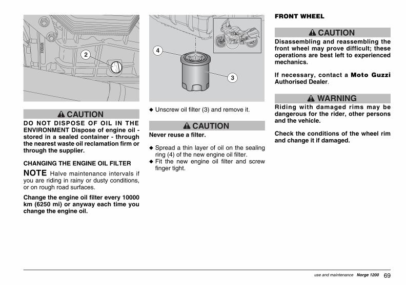
69use and maintenance Norge 1200
FRONT WHEEL
CAUTIONDisassembling and reassembling thefront wheel may prove difficult; theseoperations are best left to experiencedmechanics.
If necessary, contact a Moto GuzziAuthorised Dealer.
WARNINGRiding with damaged rims may bedangerous for the rider, other personsand the vehicle.
Check the conditions of the wheel rimand change it if damaged.
GUZum_norge1200#06_###e.book Page 69 Saturday, May 27, 2006 12:55 PM
CAUTIONDO NOT DISPOSE OF OIL IN THEENVIRONMENT Dispose of engine oil -stored in a sealed container - throughthe nearest waste oil reclamation firm orthrough the supplier.
CHANGING THE ENGINE OIL FILTER
NOTE Halve maintenance intervals ifyou are riding in rainy or dusty conditions,or on rough road surfaces.
Change the engine oil filter every 10000km (6250 mi) or anyway each time youchange the engine oil.
u Unscrew oil filter (3) and remove it.
CAUTIONNever reuse a filter.
u Spread a thin layer of oil on the sealingring (4) of the new engine oil filter.
u Fit the new engine oil filter and screwfinger tight.
2
3
4

SASSEMBLY
CAUTIONke sure that the vehicle is stable.
Rotate the wheel manually until bringingthe space between two wheel spokesbefore the brake calliper.Have someone keep the handlebarsteady in a position as for riding, so thatthe steering is locked.
ake calliper screws (1) tighteningrque: 50 Nm (5 kgm).
Unscrew and remove the two brakecalliper screws (1).
CAUTION not operate the brake lever after
moving the calliper, otherwise thestons may slip out of their seats,ding to brake fluid leakage.
ould this happen, contact your Motozzi Authorised Dealer, who will
ctify the problem.
Withdraw the brake calliper (2) from thedisc, leaving it attached to the hose (3).
GUZum_norge1200#06_###e.book Page 70 Saturday, May 27, 2006 12:55 PM
use and maintenance Norge 120070
REAR WHEEL
CAUTIONDisassembling and reassembling therear wheel may prove difficult; theseoperations are best left to experiencedmechanics.
If necessary, contact a Moto GuzziAuthorised Dealer.
WARNINGRiding with damaged rims may bedangerous for the rider, other personsand the vehicle.
Check the conditions of the wheel rimand change it if damaged.
FRONT BRAKE CALLIPERCarefu l ly read page 62(MAINTENANCE).
WARNINGA dirty disc will soil the pads, leading toloss of braking efficiency. Dirty padsmust be replaced, while dirty discsmust be cleaned with a high-qualitydegreaser.
CAUTIONWhen disassembling and reassembling,be careful not to damage the brakehoses, the discs and the pads.
NOTE To remove the f ront brakecalliper, the vehicle must be kept uprightand safely supported, with the front wheelraised off the ground.
DI
Ma
u
u
Brto
u
Dorepilea
ShGure
u
2
31

71use and maintenance Norge 1200
Check as follows:u Keep the vehicle in vertical position, the
two wheels resting on the ground.u Undo and remove the level plug (1).u Check that oil level is just below the hole
for the level plug (1). Top up if oil isbelow the specified level.
To top up or change cardan shaft oil,contact a Moto Guzzi AuthorisedDealer.
CHECKING GEARBOX FLUID LEVELu To check, top up and change gearbox
oil, contact a Moto Guzzi AuthorisedDealer.
GUZum_norge1200#06_###e.book Page 71 Saturday, May 27, 2006 12:55 PM
REASSEMBLY
CAUTIONProceed with care, in order not todamage the brake pads.
u Position the brake calliper (2) to the discso that the calliper mounting holesmatch the support holes.
WARNINGOn assembly, replace both calliperretaining screws (1) with new ones ofthe same type.
u Screw and tighten the two calliperretaining screws (1).
Brake calliper screws tightening torque:50 Nm (5 kgm).
CAUTIONAfter reassembly, operate the brakelever repeatedly and check the brakingsystem for proper operation.
CHECKING THE CARDAN SHAFT OIL LEVEL
NOTE Halve maintenance intervals ifyou are riding in rainy or dusty conditions,or on rough road surfaces.
Check cardan shaft oil level at regularintervals; change the oil after the first 1000km (625 mi) and then every 20000 km(12500 mi).
1

tting the rear-view mirrorsSit astride the vehicle, see page 49(GETTING ON AND OFF THEVEHICLE).
CAUTIONndle parts with care.
Turn mirror (2) and set correct slant.
peat the procedure to set the otherrror.Ensure there are no dirty residues.
GUZum_norge1200#06_###e.book Page 72 Saturday, May 27, 2006 12:55 PM
use and maintenance Norge 120072
REAR-VIEW MIRRORS
WARNINGDo not ride with rear-view mirrorsincorrectly set.Before leaving, always ensure they arecorrectly set.
WARNINGWear clean gloves or use a clean clothto adjust rear-view mirrors position tokeep the reflecting surface clean, andensure proper visibility.
REMOVING THE REAR-VIEW MIRRORSu Place the vehicle on the stand, see page
60 (PUTTING THE VEHICLE ON THESTAND).
u Loosen the locknut (1).
CAUTIONOn reassembly, before tightening nut(1), ensure that the mirror support rod iscorrectly positioned in line with thehandlebar.
u Slide up and remove the complete rear-view mirror unit.
Repeat the procedure to remove the othermirror, if necessary.
Seu
Ha
u
Remiu
21

73use and maintenance Norge 1200
FRONT SUSPENSIONu Have the fork oil seals changed by a
Moto Guzzi Authorised Dealer after thefirst 30000 km (18750 mi) and thenevery 20000 km (12500 mi).
If the pads and/or the disc do not needreplacing, top up fluid level.If the pads and/or the disc do not needreplacing, top up fluid level.
GUZum_norge1200#06_###e.book Page 73 Saturday, May 27, 2006 12:55 PM
INSPECTING THE FRONT AND REAR SUSPENSIONS
Carefu l ly read page 62(MAINTENANCE).
NOTE Have the front fork oil changed bya Moto Guzzi Authorised Dealer, who willensure prompt, accurate service.
NOTE Halve maintenance intervals ifyou are riding in rainy or dusty conditions,on rough road surfaces or when the vehicleis used in competitions.
Have the front fork oil changed after thefirst 10000 km (6250 mi) and then every20000 km (12500 mi).
Carry out the following checks after the first1000 km (625 mi) and every 10000 km(6250 mi) afterwards:
u Keep the front brake lever pulled in andpush down on the handlebar repeatedlyto compress the front fork. The forkshould compress in a smooth movementand must show no traces of oil on thelegs.
u Ensure that all components are properlytightened and check the front and rearsuspension articulated joints for correctoperation.
CAUTIONIn the event of faulty operation or if youneed qualified assistance, contact yourMoto Guzzi Authorised Dealer.

AILABLE SETTINGSandard setting:er only.dium load setting:ch as for rider & passenger or withgage).ximum load setting:ch as for rider, passenger and luggage).
WARNINGt spr ing pre load and reboundmping according to vehicle usage.
hen you increase spring preload, youll have to increase rebound dampingcordingly to avoid unexpected
rking when riding. If necessary,ntact your Moto Guzzi Authorisedaler. Test ride the vehicle until thetimum setting is obtained.
GUZum_norge1200#06_###e.book Page 74 Saturday, May 27, 2006 12:55 PM
use and maintenance Norge 120074
REAR SUSPENSIONThe rear suspens ion cons is ts o f aspring/damper unit that is connected to theframe and to the rear swinging arm throughcush drive rubbers and a linkage system,respectively.
For set t ing adjustments, the shockabsorber has√ an adjuster (1) for rebound hydraulic
damping;√ an adjusting knob (2) for spring (3)
preload adjustment.
ADJUSTING THE REAR SHOCKABSORBERCheck the rear shock absorber every10000 km (6250 mi) and adjust asrequired.
Standard rear shock absorber setting ismade to suit most riding conditions at lowand high speed, for carrying the rider withluggage.
However, suspension setting may bemod i f ied to su i t spec i f i c needs inaccordance with vehicle use.
WARNINGAllow the engine and silencer to cooldown before working the adjusters.
Remove the right side pannier and rearleft side body panel, see page 47(REMOVING THE REAR LEFT SIDEBODY PANEL) on models that are fittedwith this equipment.
AVStridMe(sulugMa(su
SedaWwiacjecoDeop
1
23

75use and maintenance Norge 1200
2
GUZum_norge1200#06_###e.book Page 75 Saturday, May 27, 2006 12:55 PM
SHOCK ABSORBERS SETTINGS
std = standard factory calibration
Rear shock absorber Fork
Load condition Preload Rebound Preload
Click from completely discharged (soft)
Click from completely preloaded (screw
completely closed)
Turns from completely preloaded
standard 8 (std) 14 (std) 8.5 (std)
medium load 35 11 8.5 (std)
maximum load max 8 8.5 (std)

WARNINGbrake pads were allowed to wearwn to the metal substrate, metal-to-tal contact with the brake disc wouldd to rattling and the brake calliperarking; this would result in loss ofaking and brake disc damage, leading a dangerous riding condition.
hen the lining material of any one of theke pads [whether front (3) or rear (4)] isrn down to nearly 1.5 mm, or when onethe wear indicators is worn away, have brake pads changed.
WARNING have them replaced, contact your
oto Guzzi Authorised Dealer.
2
4 1,5 mm
GUZum_norge1200#06_###e.book Page 76 Saturday, May 27, 2006 12:55 PM
use and maintenance Norge 120076
CHECKING THE BRAKE PADS FOR WEAR
Carefully read page 35 (BRAKE FLUID -recommendations), page 36 (DISCBRAKES) and page 62(MAINTENANCE).
NOTE The following information appliesto both braking systems.
NOTE Halve maintenance intervals ifyou are riding in rainy or dusty conditions,on rough road surfaces or when the vehicleis used in competitions.
Check the brake pads for wear after thefirst 1000 km (625 mi), every 2000 km(1250 mi) afterwards and before each ride. The rate at which brake pads will weardepends on vehicle usage, riding style androad surface condition.
WARNINGZ Check the brake pads for wear ,possibly before each ride.
Outlined below is a quick brake padinspection procedure:
u Place the vehicle on the stand, see page60 (PUTTING THE VEHICLE ON THESTAND).
u Visually inspect the area between brakedisc and brake pads proceeding asfollows:
√ look from above at the rear to check thefront brake calliper (1);
√ on vehicle opposite side, through therim, to check the rear brake calliper (2).
If domeleaspbrto
Wbrawoof all
ToM
1 2
1
3
1
11,5 mm1,5 mm

77use and maintenance Norge 1200
SPARK PLUGS
CAUTIONThe following instructions apply only toouter spark plugs (1). This vehicle isalso fitted with two inner spark plugs(2); contact a Moto Guzzi AuthorisedDealer to have them replaced.Carefu l ly read page 62(MAINTENANCE).
NOTE Halve maintenance intervals ifyou are riding in rainy or dusty conditions,on rough road surfaces or when the vehicleis used in competitions.
CAUTIONCheck, clean or replace the outer sparkplugs (1), one at a time.Change the outer spark plugs (1) every10000 km (6250 mi).
1 1
22
GUZum_norge1200#06_###e.book Page 77 Saturday, May 27, 2006 12:55 PM
ADJUSTING THE THROTTLE CONTROL
Carefu l ly read page 62(MAINTENANCE).
NOTE Halve maintenance intervals ifyou are riding in rainy or dusty conditions,on rough road surfaces or when the vehicleis used in competitions.
Have the throttle control cables checked bya Moto Guzzi Authorised Dealer after thefirst 1000 km (625 mi) and then every10000 km (6250 mi).
There should be 2-3 mm free play in thethrottle twistgrip (measured at twistgripedge).
If not so:u Place the vehicle on the stand, see page
60 (PUTTING THE VEHICLE ON THESTAND).
u Withdraw the protection (1).u Loosen the lock nut (2).u Rotate the adjuster (3) until obtaining the
specified free play.u When finished, tighten the lock nut (2)
and check free play again.u Refit the protection (1).
CAUTIONWhen finished, turn the handlebar tomake sure its movement does not affectthe engine idle rpm and check that thethrottle grip - when opened and thenreleased - returns smoothly to theclosed position.
2 3 1

pection and cleaning:
CAUTION not clean the spark plugs with a wireush and/or abrasive products, usempressed air only.
y:centre electrode (5);insulator (6);side electrode (7).Check electrodes and insulator forcarbon deposits or traces of corrosionand blow them with compressed air ifneeded.
ays change a spark plug which has acked insulator, corroded electrodes,
cessive deposits or when the tip (8) of central electrode (5) is rounded fromar.
5
76
8
GUZum_norge1200#06_###e.book Page 78 Saturday, May 27, 2006 12:55 PM
use and maintenance Norge 120078
CAUTIONEven if only one outer spark plug (1)needs replacing, always change both.
WARNINGBefore carrying out the followingoperations, let the engine and thesi lencer cool down to ambienttemperature to avoid burns.
The following procedures apply to bothcylinders.
Removal:
u Remove the spark plug cap (3).u Remove any trace of dirt from the spark
plug base.u Fit the special socket included in the tool
kit to the spark plug.u Insert the spanner (4) included in the tool
kit into the hexagonal seat of the sparkplug socket.
u Unscrew the spark plug and remove itfrom its seat, making sure no dust or dirtcan fall into the cylinder.
Ins
Dobrco
Ke√√√u
Alwcraexthewe
3 4

79use and maintenance Norge 1200
CHECKING THE STAND
Carefully read page 62 (MAINTENANCE)and page 84 (CHECKING THESWITCHES).
The vehicle is equipped with two stands:
√ side stand (1);√ centre stand (2).The stand features two positions:√ standard or up (at rest);√ down.Operation of the stand is the rider'sresponsibility.
The stand should turn smoothly.The springs (3) keep the stand in thedesired position (extended or retracted).
2 31 3
GUZum_norge1200#06_###e.book Page 79 Saturday, May 27, 2006 12:55 PM
CAUTIONOnly use recommended spark plugs,see page 96 (TECHNICAL DATA) or theengine performance and life-span mightbe impaired.
Electrode gap should be checked usinga wire gauge (9) to avoid damaging theplatinum coating.
u Check electrode gap with a wire gauge(9).
CAUTIONNever attempt to adjust electrode gap.
Electrode gap should be 0.6 - 0.7 mm. Ifnot so, change the spark plug.
u Make sure that the washer (10) is ingood condition.
Installation:
u Position the washer (10) and screw inthe spark plug by hand in order not todamage the thread.
u Tighten each spark plug by one half of aturn to compress the washer using thesocket included in the tool kit.
Spark plug tightening torque: 20 Nm (2kgm).
CAUTIONThe spark plug must be tightenedfirmly, otherwise the engine mayoverheat and severe damage mayoccur.
u Position the spark plug cap properly, toprevent it coming off due to enginevibration.
NOTE Repeat the above procedure forthe spark plug of the other cylinder.
10
9

e side stand (1) is equipped with afety switch (4) that inhibits ignition orps the engine whenever a gear is
gaged while the side stand (1) is down.
determine proper operation of thefety switch (4), proceed as follows:Sit astride the vehicle.Fold up the side stand (1).Start the engine, see page 53(STARTING).With the throttle twistgrip (5) released(Pos. A), let engine idle and pull theclutch lever (6) fully in.Push down the gear shift lever (7) toengage the first gear.Lower the side stand (1) to operate thesafety switch (4).
1
4
GUZum_norge1200#06_###e.book Page 80 Saturday, May 27, 2006 12:55 PM
use and maintenance Norge 120080
CENTRE STANDu Place the vehicle on the side stand, see
page 60 (PUTTING THE VEHICLE ONTHE STAND).
u The springs (3) must not be damaged,worn, rusty or weakened.
u Ensure that the stand has no play whenup.
u Move the stand and release it, checkthat the springs move it completely back.
u The stand should turn smoothly: smearthe joint with grease, if necessary, seepage 99 (LUBRICANT CHART).
SIDE STANDu Place the vehicle on the centre stand,
see page 60 (PUTTING THE VEHICLEON THE STAND).
u The springs (3) must not be damaged,worn, rusty or weakened.
u Make sure that the stand has no play ineither position (extended and retracted).
u Lower the stand to make sure thesprings let it extend completely.
u Pull the stand midway up and let go tomake sure the springs let it retractcompletely.
u The stand should turn smoothly: smearthe joint with grease, if necessary, seepage 99 (LUBRICANT CHART).
Thsastoen
Tosau
u
u
u
u
u
3
7
5
6
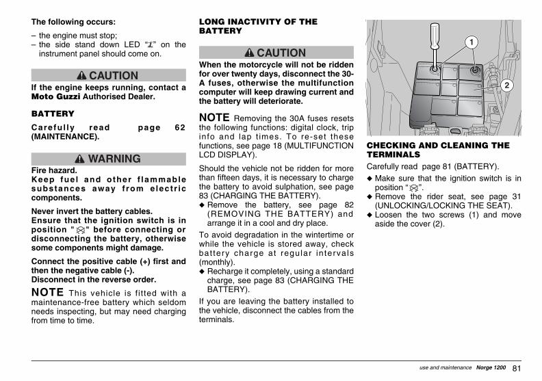
81use and maintenance Norge 1200
CHECKING AND CLEANING THE TERMINALSCarefully read page 81 (BATTERY).
u Make sure that the ignition switch is inposition ≈ ∆.
u Remove the rider seat, see page 31(UNLOCKING/LOCKING THE SEAT).
u Loosen the two screws (1) and moveaside the cover (2).
1
2
GUZum_norge1200#06_###e.book Page 81 Saturday, May 27, 2006 12:55 PM
The following occurs:
√ the engine must stop;√ the side stand down LED ≈ ∆ on the
instrument panel should come on.
CAUTIONIf the engine keeps running, contact aMoto Guzzi Authorised Dealer.
BATTERY
Carefu l ly read page 62(MAINTENANCE).
WARNINGFire hazard.Keep fue l and other f lammablesubstances away f rom e lect r iccomponents.
Never invert the battery cables.Ensure that the ignition switch is inposition " " before connecting ordisconnecting the battery, otherwisesome components might damage.
Connect the positive cable (+) first andthen the negative cable (-).Disconnect in the reverse order.
NOTE This vehicle is f i t ted with amaintenance-free battery which seldomneeds inspecting, but may need chargingfrom time to time.
LONG INACTIVITY OF THE BATTERY
CAUTIONWhen the motorcycle will not be riddenfor over twenty days, disconnect the 30-A fuses, otherwise the multifunctioncomputer will keep drawing current andthe battery will deteriorate.
NOTE Removing the 30A fuses resetsthe following functions: digital clock, tripinfo and lap t imes. To re-set thesefunctions, see page 18 (MULTIFUNCTIONLCD DISPLAY).
Should the vehicle not be ridden for morethan fifteen days, it is necessary to chargethe battery to avoid sulphation, see page83 (CHARGING THE BATTERY).u Remove the battery, see page 82
(REMOVING THE BATTERY) andarrange it in a cool and dry place.
To avoid degradation in the wintertime orwhile the vehicle is stored away, checkbat tery charge at regular in terva ls(monthly).u Recharge it completely, using a standard
charge, see page 83 (CHARGING THEBATTERY).
If you are leaving the battery installed tothe vehicle, disconnect the cables from theterminals.
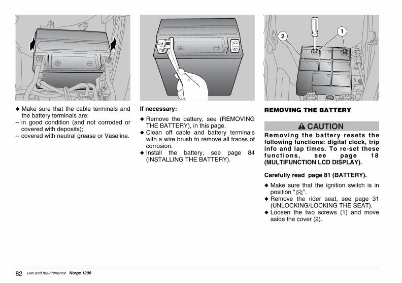
MOVING THE BATTERY
CAUTIONmoving the battery resets the
llowing functions: digital clock, tripfo and lap times. To re-set thesenct ions , see page 18ULTIFUNCTION LCD DISPLAY).
refully read page 81 (BATTERY).
Make sure that the ignition switch is inposition ≈ ∆.Remove the rider seat, see page 31(UNLOCKING/LOCKING THE SEAT).Loosen the two screws (1) and moveaside the cover (2).
12
GUZum_norge1200#06_###e.book Page 82 Saturday, May 27, 2006 12:55 PM
use and maintenance Norge 120082
u Make sure that the cable terminals andthe battery terminals are:
√ in good condition (and not corroded orcovered with deposits);
√ covered with neutral grease or Vaseline.
If necessary:
u Remove the battery, see (REMOVINGTHE BATTERY), in this page.
u Clean off cable and battery terminalswith a wire brush to remove all traces ofcorrosion.
u Install the battery, see page 84(INSTALLING THE BATTERY).
RE
Refoinfu(M
Ca
u
u
u
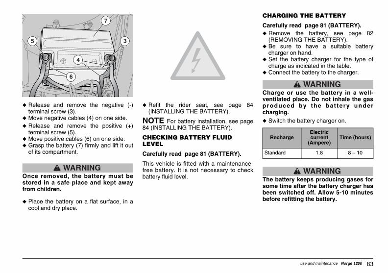
83use and maintenance Norge 1200
CHARGING THE BATTERY
Carefully read page 81 (BATTERY).u Remove the battery, see page 82
(REMOVING THE BATTERY).u Be sure to have a suitable battery
charger on hand.u Set the battery charger for the type of
charge as indicated in the table.u Connect the battery to the charger.
WARNINGCharge or use the battery in a well-ventilated place. Do not inhale the gasproduced by the bat tery undercharging.u Switch the battery charger on.
WARNINGThe battery keeps producing gases forsome time after the battery charger hasbeen switched off. Allow 5-10 minutesbefore refitting the battery.
RechargeElectric current
(Ampere)Time (hours)
Standard 1.8 8 √ 10
GUZum_norge1200#06_###e.book Page 83 Saturday, May 27, 2006 12:55 PM
u Release and remove the negative (-)terminal screw (3).
u Move negative cables (4) on one side.u Release and remove the positive (+)
terminal screw (5).u Move positive cables (6) on one side.u Grasp the battery (7) firmly and lift it out
of its compartment.
WARNINGOnce removed, the battery must bestored in a safe place and kept awayfrom children.
u Place the battery on a flat surface, in acool and dry place.
u Refit the rider seat, see page 84(INSTALLING THE BATTERY).
NOTE For battery installation, see page84 (INSTALLING THE BATTERY).
CHECKING BATTERY FLUID LEVEL
Carefully read page 81 (BATTERY).
This vehicle is fitted with a maintenance-free battery. It is not necessary to checkbattery fluid level.
3
7
5
4
6

ECKING THE SWITCHESre fu l ly read page 62
AINTENANCE).
e vehicle is equipped with fouritches:Stop light switch on the rear brakecontrol lever;Stop light switch on the front brakecontrol lever;Safety switch on the side stand;Switch on the clutch lever.
1
2
GUZum_norge1200#06_###e.book Page 84 Saturday, May 27, 2006 12:55 PM
use and maintenance Norge 120084
INSTALLING THE BATTERY
Carefully read page 81 (BATTERY).
u Make sure that the ignition switch is inposition ≈ ∆.
u Remove the rider seat, see page 31(UNLOCKING/LOCKING THE SEAT).
NOTE The bat tery (1) should bepositioned in its housing with the terminalsfacing the vehicle front end.
u Insert the battery (1) in its compartment.
WARNINGUpon reassembly, connect the positivecable (+) first and then the negativecable (-).
u Connect the positive (+) cable bytightening the terminal screw (2).
u Connect the negative (-) cable bytightening the terminal screw (3).
u Coat the terminals of cables and batterywith neutral grease or Vaseline.
u Install the battery in the correct position,fully into its seat.
u Tighten the screws (5) to secure thecover (4).
u Refit the rider seat, see page 31(UNLOCKING/LOCKING THE SEAT).
CAUTIONRemoving the battery resets thefollowing functions: digital clock, tripinfo and lap times. To re-set thesefunct ions, see page 18(MULTIFUNCTION LCD DISPLAY).
CHCa(M
Thsw1)
2)
3)4)
3
1
2
5
4

85use and maintenance Norge 1200
In this case it is advisable to contact aMoto Guzzi Authorised Dealer.
Checking the fuses is recommendedwhenever an electric component fails tooperate or is malfunctioning, or when theengine does not start.
First check auxiliary fuses (2), ABS fuses(3) and then main fuses (4).
4
GUZum_norge1200#06_###e.book Page 85 Saturday, May 27, 2006 12:55 PM
u Clean the switch if caked with dirt ormud. The pin must move freely andreturn automatically to its initial position.
u Make sure that the cables are connectedcorrectly.
CHANGING THE FUSES
Carefu l ly read page 62(MAINTENANCE).
CAUTIONDo not repair faulty fuses.Never use a fuse of a rating other thanspecified.This could damage the electric systemor cause a short circuit, with the risk offire.
NOTE If a fuse blows repeatedly, theremight be a short circuit or an overload inthe electric system.
3
4
12

RANGEMENT OF AUXILIARY FUSES Stop, horn, HAZARD button light, lightrelay coil (15A).Parking lights, starter relay coil, passing(15A).Fuel pump, coils, injectors (20A).Lambda burner, secondary injectionrelay coil, starter relay coil, speedsensor power (15A).Permanent positive, ECU power (3A).ABS (10A) .
OTE There are three spare fuses (3,, 20 A).
ef d c b a
GUZum_norge1200#06_###e.book Page 86 Saturday, May 27, 2006 12:55 PM
use and maintenance Norge 120086
Check as follows:u Set the ignition switch to " " to avoid
an accidental short circuit.u Remove the rider seat, see page 31
(UNLOCKING/LOCKING THE SEAT).u Open the auxiliary fuses (2) carrier (1)
cover.u Extract and check the fuses one by one -
a divided link bar (5) means that the fuseis blown.
u Before replacing a fuse, identify thecause of the failure if possible.
u Replace the blown fuse with a new onewith equal current rating.
NOTE When you use one of the sparefuses, remember to add a new spare fuseinto the proper seat.
u Repeat the above operations for themain fuses.
NOTE Removing the 30A fuses resetsthe following functions: digital clock, tripinfo and lap times.
To re-set these functions, see page 18(MULTIFUNCTION LCD DISPLAY).
ARa)
b)
c)d)
e)f)
N15
4
3
5

87use and maintenance Norge 1200
BEAM SETTING
NOTE Beam inspection procedures mayvary from country to country. Observe thelaw in force in the country of the user.
For a quick beam inspection, place thevehicle on level ground, ten metres awayfrom a vertical wall.
Switch on the low beam, sit astride thevehicle and make sure that the light spoton the wall is just below the horizontal lineof the headlight (about nine/tenths ofoverall height).
GUZum_norge1200#06_###e.book Page 87 Saturday, May 27, 2006 12:55 PM
LAYOUT OF THE ABS FUSES g) ABS (40A) .h) ABS (25A) .
ARRANGEMENT OF MAIN FUSES i) From battery to voltage regulator (30A).j) From battery to key and C and D fuses
(30A).
NOTE There is one spare fuse.
l
h
g
i
i
l
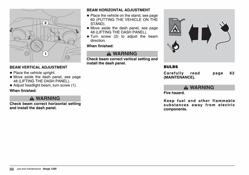
LBS
re fu l ly read page 62AINTENANCE).
WARNINGe hazard.
ep fue l and other f lammablebstances away f rom e lect r icmponents.
GUZum_norge1200#06_###e.book Page 88 Saturday, May 27, 2006 12:55 PM
use and maintenance Norge 120088
BEAM VERTICAL ADJUSTMENTu Place the vehicle upright.u Move aside the dash panel, see page
48 (LIFTING THE DASH PANEL).u Adjust headlight beam, turn screw (1).
When finished:
WARNINGCheck beam correct horizontal settingand install the dash panel.
BEAM HORIZONTAL ADJUSTMENTu Place the vehicle on the stand, see page
60 (PUTTING THE VEHICLE ON THESTAND).
u Move aside the dash panel, see page48 (LIFTING THE DASH PANEL).
u Turn screw (2) to adjust the beamdirection.
When finished:
WARNINGCheck beam correct vertical setting andinstall the dash panel.
BU
Ca(M
Fir
Kesuco
1
2

89use and maintenance Norge 1200
HIGH BEAM BULB (2)
Do not pull on the wires to extract thebulb connector.
u Remove the rubber protection (4).u Disconnect the connectors (5).u Release the two ends of the retainer (6)
and remove the bulb, fit a new onehaving the same rating, see page 96(TECHNICAL DATA).
NOTE Insert the bulb into the bulbholder, making sure to match the locatingslots.
u Refit the bulb in its seat and lock it inplace using the retainer (6).
u Connect connectors (5) and refit therubber protection (4).
u Install the dash panel.
45
6
4
GUZum_norge1200#06_###e.book Page 89 Saturday, May 27, 2006 12:55 PM
CAUTIONBefore changing a bulb, move theignition switch to position “ ” andwait a few minutes, so that the bulbcools down.
Wear clean gloves or use a clean, drycloth to handle the new bulb.
Do not put your fingerprints on thebulb, as this may lead to overheatingand failure.
If you have handled the bulb with barehands, clean it with alcohol to avoid anydamage.
DO NOT PULL ON THE WIRES.
NOTE Before changing a bulb, checkthe fuses, see page 85 (CHANGING THEFUSES).
CHANGING THE HEADLIGHT BULBSCarefully read page 88 (BULBS).
The headlight houses:
√ two low beam bulbs (upper) (1);√ two high beam bulbs (lower) (2);√ two parking light bulbs (lower) (3);To change oil:u Place the vehicle on the stand, see page
60 (PUTTING THE VEHICLE ON THESTAND).
u Move aside the dash panel, see page48 (LIFTING THE DASH PANEL).
3
2
1

ANGING THE FRONT AND REAR RN INDICATOR BULBS
refully read page 88 (BULBS).
Place the vehicle on the stand, see page60 (PUTTING THE VEHICLE ON THESTAND).Unscrew and remove the screw (9).
CAUTIONhile removing the lens, proceedrefully in order not to break theating peg.
Remove the lens (10).
910
GUZum_norge1200#06_###e.book Page 90 Saturday, May 27, 2006 12:55 PM
use and maintenance Norge 120090
LOW BEAM BULB (1)
Do not pull on the wires to extract thebulb connector.
u Follow the same procedure as describedfor the high beam.
PARKING LIGHT BULB
Do not pull on the wires to extract thebulb connector.
u Grasp the parking light (7) bulb holderand pull to extract.
u Remove the bulb (8) and fit a new bulb ofequal rating.
u Reinstall the lamp holder (7) in its seat.
CHTU
Ca
u
u
Wcaloc
u
45
6
47
8
91use and maintenance Norge 1200
GUZum_norge1200#06_###e.book Page 91 Saturday, May 27, 2006 12:55 PM
CAUTIONMake sure that the lens locatescorrectly into its seat on refitting.Tighten the screw (9) moderately andcarefully, to avoid damaging the lens.
u Press the bulb slightly and rotate itanticlockwise.
u Extract the bulb from its seat.
CAUTIONInsert the bulb into the bulb holder, sothat the two pins slide into the slots inthe holder.
u Fit a new bulb of equal rating.
CAUTIONIf the bulb holder comes off, refit it intoits seat so that the chamfered openingof the holder matches the hole for thescrew.
CHANGING THE TAIL LIGHT BULBThis vehicle fits a LED tail light, have itreplaced by a Moto Guzzi AuthorisedDealer.
REPLACING THE NUMBER PLATE BULBSince this operation is quite complex, haveit performed by a Moto Guzzi AuthorisedDealer.

Place the vehicle on the centre stand onfirm and level ground.Stop the engine and wait until it hascooled down. Prepare a container large enough tohold the fuel in the tank and place it onthe floor on the left side of the vehicle.Remove the fuel filler plug.Drain fuel using a manual pump orsimilar system. Do not damage the fuelpump assembly (fuel level sensoraccommodated inside the tank).
WARNINGfit the filler plug after draining all fuel.
GUZum_norge1200#06_###e.book Page 92 Saturday, May 27, 2006 12:55 PM
use and maintenance Norge 120092
TRANSPORT
WARNINGBefore transporting the vehicle, it isnecessary to empty the fuel tankcompletely, see page 92 (DRAININGTHE FUEL TANK), making sure that it iscompletely dry.
During transport, the vehicle must befirmly secured in an upright position toavoid fuel, oil and coolant leaks.
If stranded, do not have the vehicletowed - contact a roadside service firminstead.
DRAINING THE FUEL TANK
Carefully read page 34 (FUEL).
WARNINGFire hazard.Allow some time for the engine andmuffler to cool down completely.Fuel vapours are harmful to humanhealth. Ensure the area is well ventilatedbefore proceeding.Do not inhale fuel vapours.Do not smoke or use open flames.
DO NOT RELEASE FUEL IN THEENVIRONMENT.
u
u
u
u
u
Re

93use and maintenance Norge 1200
To remove dirt and mud from paintedsurfaces, use a low-pressure water jet ondirty areas, remove mud and dirt with a softcar body sponge soaked with abundantwater and shampoo (2 - 4% parts ofshampoo).
Then rinse with plenty of water and dry withchamois leather.
Clean the outer parts of the engine using adegreaser, small brushes and cloth.
CAUTIONBefore washing the vehicle
GUZum_norge1200#06_###e.book Page 93 Saturday, May 27, 2006 12:55 PM
CLEANING
Clean the vehicle frequently if it is used inparticular areas or conditions, such as:
u Polluted areas (town and industrialareas).
u High salinity and humidity (sea areas,hot and damp climates).
u Seasonal/environmental conditions(road salt and chemicals spread on theroads in the wintertime).
u Make sure to clean off any industrialresidue and pollutants, tar, dead insects,bird droppings, etc. from the body panelsand fairings.
u Avoid parking the vehicle under trees.Resins, fruits or leaves falling from thetrees may contain chemical substancesthat may damage the paintwork.
WARNINGAfter the vehicle has been washed,braking efficiency could be temporarilyimpaired because the friction surfacesof the braking systems may still be wet.Ride carefully as braking distance willbe longer . Operate the brakesrepeatedly to restore normal operation.Carry out the pre-ride checks, see page52 (PRE-RIDE CHECKS CHART).

NG PERIODS OF INACTIVITY
CAUTIONhe vehicle will not be ridden for morean twenty days, disconnect the 30Ases to avoid deterioration of thettery.
OTE Removing the 30A fuses resets following functions: digital clock, trip
o and lap times. To re-set this function,e page 18 (MULTIFUNCTION LCDSPLAY).
hen the vehicle will not be ridden for longriods, some precautions are necessaryavoid damage. not postpone necessary repairs or youy forget them when you take the vehicle
t of storage; a general check up is alsoommended.
GUZum_norge1200#06_###e.book Page 94 Saturday, May 27, 2006 12:55 PM
use and maintenance Norge 120094
1) Empty the front and under-seatcompartments;
2) Make sure the compartments areproperly closed.
CAUTIONWash with mild soap and rinse withwater not under pressure (please readthis manual, on page 93 (CLEANING).
CAUTIONTo clean the lights, use a spongesoaked with water and a mild detergent,rubbing the surfaces delicately andrinsing frequently with plenty of water.
CAUTIONPolish with silicone wax only aftercarefully washing the vehicle.
Do not use polishing pastes on mattpaints.
Do not wash the vehicle under the sun,especially in the summertime, when thebody is still warm, as the shampoo willdry before you can rinse it away andcould damage the paint.
Do not use fluids at a temperaturehigher than 40°C to clean the plasticcomponents of the vehicle.
CAUTIONDo not aim high-pressure water/air jetsor steam jets at the following parts:wheel hubs, controls on the right andleft side of the handlebar, bearings,brake master cylinders, instrumentsand indicators, si lencer exhaust,glove/tool kit compartment, ignitionswitch/steering lock.
Do not use alcohol, fuel or solvents toclean the rubber and plastic parts: useonly water and mild soap.
Do not use solvents or oil-derived fluids(such as acetone, trichloroethylene,turpentine, fuel, thinners) to clean theseat. You can use detergents withsurface-active agents up to 5% (mildsoap, degreasing agents or alcohol).
Carefully dry the seat after cleaning.
WARNINGDo not apply protection waxes to theseat, or it may become slippery.
LO
If tthfuba
NtheinfseDI
Wpeto Domaourec

95use and maintenance Norge 1200
GUZum_norge1200#06_###e.book Page 95 Saturday, May 27, 2006 12:55 PM
Proceed as follows:u Remove the battery, see page 82
(REMOVING THE BATTERY) and page81 (LONG INACTIV ITY OF THEBATTERY).
u Wash and dry the vehicle, see page 93(CLEANING).
u Polish painted surfaces with wax.u Inflate the tyres, see page 43 (TYRES).u Store the vehicle in an unheated, dry
place, away from sunl ight, wheretemperature is reasonably steady.
u Wrap and tie a plastic bag around theexhaust pipe openings to keep moistureout.
NOTE Place the vehicle on stablesupports to keep both wheels off theground.
u Cover the vehicle avoiding plastic orwaterproof covers.
AFTER STORAGE
NOTE Remove the plastic bags from theexhaust silencers.
u Remove the covers and clean thevehicle, see page 93 (CLEANING).
u Check the battery charge, see page 83(CHARGING THE BATTERY) and installit, see page 84 (INSTALLING THEBATTERY).
u Fill the fuel tank, see page 34 (FUEL).u Carry out the pre-ride checks, see page
52 (PRE-RIDE CHECKS CHART).
WARNINGTest ride the vehicle at moderate speedin an area away from traffic.

der, 4-stroke
rpm
ent through valves and gear pump
control on the left side of the engine
c
uggage)
GUZum_norge1200#06_###e.book Page 96 Saturday, May 27, 2006 12:55 PM
use and maintenance Norge 120096
TECHNICAL DATA
DIMENSIONS Max. Length 2195 mmMax. width (at handlebar) 870 mmMax. height (at windscreen) Max 1405 mm - Min 1365 mmSeat height 800 mmWheelbase 1495 mmMinimum ground clearance 185 mmDry weight 246 kg
ENGINE Model V 1200 IEType 90° traverse V-type, twin-cylinNumber of cylinders 2Displacement 1151 cc Bore / stroke 95x81.2 mm Compression ratio 9.8: 1Maximum power above 65 kW (90 CV) at 7500Starting electricEngine idling rpm 1100 Ø 100 rpmClutch twin-plate, dryLubrication system pressure-fed system, adjustmAir filter cartridge, dryCooling air
GEARBOX Type mechanical, 6 gears with foot
CAPACITIES Fuel (reserve included) 23 bFuel reserve 4 bEngine oil oil and oil filter change 3600 cGearbox fluid 500 ccTransmission fluid 380 ccFork fluid 400 Ø 2.5 cu cm (per leg)Seats 2Max vehicle load 230 kg (rider + passenger + l

97use and maintenance Norge 1200
Final ratioCompact Reactive Shaft Drive - CA.R.C.Double universal joint with floating bevelgear 12/44 = 1 : 3.666
int Magneti Marelli electronic injection IAW5A,m throttle bodies with Weber IW031 injectors,r
petrol, minimum octane rating 95 (ROM) and 85
es that can be disassembled, high-strength steel
pic fork, with adjustable spring preload.
ith progressive linkage, monoshock with adjustablec knob for preload adjustment.
less steel Æ 320 mm, callipers with 4 opposite
2 mm, floating calliper with two parallel pistons
ium alloy, chill cast
- MICHELIN Pilot Road - DUNLOP D220 ST
(250 kPa)senger: 2.5 atm (250 kPa)
GUZum_norge1200#06_###e.book Page 97 Saturday, May 27, 2006 12:55 PM
DRIVE RATIOS
Ratio Primary Final1st gears 17/38 = 1 : 2.2352nd 24/35 20/34 = 1 : 1.700
3rd 23/31 = 1 : 1.3474th 26/29 = 1 : 1.1155th 31/30 = 1 : 0.9676th 29/25 = 1 : 0.862
FUEL FEED SYSTEM
Type sequential, timed, multipoalpha-n system; 2 Æ 40mclosed loop lambda senso
Throttle Æ 40 mm
FUEL SUPPLY Fuel Premium-grade unleaded (MON).
FRAME Type Tube frame with two cradlSteering angle 32°Trail 120 mm
SUSPENSIONS Front Æ 45 mm hydraulic telescoStroke 120 mmRear single-sided swinging arm w
rebound and with ergonomiWheel travel 140 mm
BRAKES Front twin floating disc in stainpistons
Rear disc in stainless steel Æ 28
WHEEL RIMS Type 3 hollow spokes in aluminFront 3.5" x 17∆Rear 5.5" x 17∆
TYRES Type METZELER Roadtec Z6Sportmax
Front Size: 120/70 - ZR 17∆ Inflating pressure: 2.5 atmInflating pressure with pas

0 kPa)ger: 2.8 atm (280 kPa)
0A0 rpm
)
GUZum_norge1200#06_###e.book Page 98 Saturday, May 27, 2006 12:55 PM
use and maintenance Norge 120098
Rear Size: 180/55 - ZR 17∆ Inflating pressure: 2.8 atm (28Inflating pressure with passen
SPARK PLUGS Inner (long life) NGK PMR8B Outer NGK BPR6ESSpark plug electrode gap 0.6 – 0.7 mm
ELECTRICAL SYSTEM Battery 12 V – 18 Amp/hMain fuses 30 AABS fuses 40 A – 25 A Auxiliary fuses 3 A √ 15 A √ 20 A √ 1Generator (with permanent magnet) 12 V – 550 W at 200
BULBS Parking light 12 V – 5 W x 2Low beam 12 V – 55 W H3 x 2High beam 12 V – 55 W H1 x 2Turn indicator light 12 V – 10 W (orangeStop/rear parking lights LEDInstrument panel lighting LEDNumber plate light 12 V – 5 W
WARNING LIGHTS Turn indicators LEDABS LEDAlarm LEDNeutral LEDSide stand down LEDHigh beam LEDFuel reserve LEDAntitheft LEDGear shift indicator LED

99use and maintenance Norge 1200
LUBRICANT CHART
(Recommended) Engine oil: RACING 4T 10W 60.As an alternative to recommended oils, top brand oils meeting or exceeding CCMC G-4 A.P.I. SG specifications can be used.
(Recommended) Transmission oil: ROTRA MP 80 W 90.
(Recommended) Gearbox oil: ROTRA MP/S 85 W 90.
(Recommended) Fork oil: FORK 5W or FORK 20W.
(Recommended) bearings and other lubrication points: GREASE SM2.As an alternative to recommended grease, use top brand rolling bearing grease that will resist a temperature range of -30°C +140°C, withdripping point 150°C - 230°C, high corrosion protection, good resistance to water and oxidisation.Battery terminals protectant: Neutral grease or Vaseline.
WARNINGUse new brake fluid only. Do not mix different brands or types of oil unless you are sure that the different oil bases are compatible.
(Recommended) brake fluid: the system is filled with BRAKE 5.1 DOT 4 (the braking system is also compatible with DOT 5).
As an alternative to the recommended product, top brand brake fluid meeting or exceeding SAE J1703, NHTSA 116 DOT 4, ISO 4925specifications for synthetic brake fluid can be used.
GUZum_norge1200#06_###e.book Page 99 Saturday, May 27, 2006 12:55 PM
use and maintenance Norge 1200100
NOTES
ASK FOR GENUINE SPARE PARTS ONLY
GUZum_norge1200#06_###e.book Page 100 Saturday, May 27, 2006 12:55 PM

101
NOTES
use and maintenance Norge 1200
ASK FOR GENUINE SPARE PARTS ONLY
GUZum_norge1200#06_###e.book Page 101 Saturday, May 27, 2006 12:55 PM

use and maintenance Norge 1200102
NOTES
ASK FOR GENUINE SPARE PARTS ONLY
GUZum_norge1200#06_###e.book Page 102 Saturday, May 27, 2006 12:55 PM

103use and maintenance Norge 1200
thorised Network engineers are familiar with and repair.
s, proper maintenance at the recommended
lease consult the Yellow Pages or the map
developed and tested as early as the vehicleedures to ensure total reliability and a long
GUZum_norge1200#06_###e.book Page 103 Saturday, May 27, 2006 12:55 PM
Thanevery
A vehinterv
To finprovi
Whendesigservi
AUTHORISED DEALERS AND SERVICE CENTRES
THE VALUE OF SERVICE
ks to ongoing technical updates and product-specific technical training, Moto Guzzi Au detail of this vehicle and have the special equipment required for correct maintenance
icle kept in sleek running order is a reliable vehicle. Other key factors are pre-ride checkals and the use of Moto Guzzi Genuine Parts only!
d contact information of the Authorised Dealer and/or Service Centre nearest you, pded at our web site:
www.motoguzzi.it
you demand Moto Guzzi Genuine Parts, you are purchasing products that have been n stage. Moto Guzzi Genuine Parts systematically undergo strict quality control procce life.
and
ts into the
GUZum_norge1200#06_###e.book Page 104 Saturday, May 27, 2006 12:55 PM
use and maintenance Norge 1200104
Moto Guzzi s.p.a. wishes to thank you for purchasing this vehicle recommends the following:
√ Do not release oil, fuel, polluting substances and componenenvironment.
√ Do not keep the engine running when not necessary.
√ Avoid disturbing noise.
√ Respect the environment.