guidelines for the hydraulic design of harbour entrances
TRANSCRIPT
Guidelines for the hydraulic design of harbour entrances
M W McBride J V Smallman N W H Allsop
Report SR 430 February 1996
Address arid Regktered Ofllce: HR Walllngford Ltd. Howbefy Park, Walllngford. Oxon OX10 8BA Tel: + 44 (0)1491 835381 Fax: + 44 (0)1491 832233


Con tract
The work described in this report was funded by the Construction Directorate of the Department of the Environment (DOE) under research contract PECD 7161298, "The hydraulic design of harbour entrances". The DOE nominated officer for this contract was Mr P B Woodhead and HR Wallingford's nominated officer was Dr W R White, Research Director. The report is published on behalf of the DOE but any opinions expressed are not necessarily those of the funding department. The research described in this report was carried out in the Ports and Estuaries Group, managed by Dr J V Smallman, and the Coastal Structures Section, managed by Professor N W H Allsop, at HR Wallingford. The HR internal job number was DAS 0042.
Prepared by d hiat hah,<
............................... (Job title)
/[ v . h Approved by .................................
20 fig 14% Date .............................
@ HR Wallingford Limited 1996


Summary
Guidelines for the hydraulic design of harbour entrances
M W McBride J V Srnallman N W H Allsop
Report SR 430 February 1996
This report provides guidelines for the hydraulic design of harbour entrances. These guidelines are particularly associated with problems resulting from wave reflections from vertically faced harbour structures. This report includes discussion and identification of the wave reflection problems in the UM, through a survey of UM port and harbours, and a description of navigation related issues. It also contains summaries of four computational and physical model studies which were carried out to investigate wave reflections from vertical walls and various type of protection measures which may be used to reduce wave reflections, and hence improve vessel navigation safety. Also included is a summary of new method for the assessment of vessel safety, with regard to sea steepness resutting from the interaction between incident and reflected waves.
The report concludes with a series of guidelines for the modification of port structures with wave reflections problems and for the construction of new port structures mitigate to such problems.


Con tents
Page
Title page Contract Summary Contents
. . . . . . . . . . . . . . . . . . . . . . . . . . . . . . . . 1 Problem definition 1
. . . . . . . . . . . . . . . . . . . . . . . . . . . . . . . . 1.1 Background 1 . . . . . . . . . . . . . . . . . . . . . . . 1.2 The situation in the UK 1
. . . . . . . . . . . . . . . . . . . . 1.3 Navigational considerations 2
. . . . . . . . . . . . . . . . . . . . . . . . . . . . . . . . 2 Summary studies 3 2.1 Computational modelling of wave disturbance . . . . . . . 3 2.2 Computational modelling of porous wave screens . . . . 4
2.2.1 The computational model . . . . . . . . . . . . . . . 4 2.2.2 Application of the model . . . . . . . . . . . . . . . . 5
. . . . . . . . . . . . . . . . . . . 2.2.3 Summary of results 5 2.3 Physical modelling of low reflection structures . . . . . . . 6
2.3.1 Test methodology . . . . . . . . . . . . . . . . . . . . 6 2.3.2 Discussion of results . . . . . . . . . . . . . . . . . . 6 2.3.3 Impact on wave conditions . . . . . . . . . . . . . . 8
2.4 Physical modelling of entrance configurations . . . . . . . 9 2.5 Application of the study results . . . . . . . . . . . . . . . . . . 9
3 Guidance for design in existing harbours . . . . . . . . . . . . . . 10 3.1 Establish understanding of the problem . . . . . . . . . . . . 10
. . . . . . . . . . 3.2 Modification of existing vertical structures 11 . . . . . . . . . . . . . . . . . . . . . . . . 3.2.1 Rock slopes 11
. . . . . . . . . . . . . 3.2.2 Perforated screendcaissons 1 1 . . . . . . . . . . . . . . . . . . . 3.2.3 Relieving plattorms 12
3.2.4 Confirmation of effect of proposed . . . . . . . . . . . . . . . . . . . . . . . . . modification 12
4 Guidance for design in new harbours . . . . . . . . . . . . . . . . . 12
5 Acknowledgements . . . . . . . . . . . . . . . . . . . . . . . . . . . . . . . 13
6 References . . . . . . . . . . . . . . . . . . . . . . . . . . . . . . . . . . . . . 14
Tables Table 1 Coefficients for equation 3. for tested wave screen
configurations Table 2 Results of sea steepness analysis
Figures Figure 1 Typical high reflection harbour entrance configurations Figure 2 Composite wave screen
Contents continued
Figure 3 Numerical model predictions for a composite wave screen
Figure 4 Influence of relative crest height on reflections Figure 5 Reflections from single chamber wave screen Figure 6 Comparison of relative wave steepness between simple
vertical wall and composite wave screen Figure 7 Vertical wall with rock armour slope Figure 8 Piled relieving platform over armoured slope
Appendices Appendix 1 Port survey questionnaire

I Problem definition
1 .l Background Previous work by McBride et al (1 993) discussed problems arising from wave reflections in harbours. It was found that these problems were caused by the use of vertical or near vertically faced structures to form harbour structures. This work also reviewed various types of 'low reflection' structures for which some performance data were known. That review was followed by studies using physical and computational models of harbour entrances which were reported by McBride et al (1995, 1995b and 1996). Those studies suggested that wave disturbance problems in many harbour entrances would be substantially reduced if wave reflections from the primary harbour structures were kept below 40%. The reflection performance of most vertical breakwaters and harbour walls falls in the range of 90 to 100%, so substantial reduction in reflections may be required.
This report summarises a series of studies carried out to identify guidelines for the hydraulic design of harbour entrances. These studies were carried out to investigate methods of reducing wave reflections from vertically faced harbour structures, and hence improve conditions for vessel navigation. They consisted of both computational and physical model studies, examining entrance configuration and orientation, low reflection structures, and vessel navigation. This chapter provides a brief description of the extent of the problem in the UK. Chapter 2 summarises the computational and physical model studies which were carried out as part of this project, Chapter 3 considers guidelines for existing port structures and Chapter 4 provides guidelines for new port structures.
1.2 The situation in the UK A review of UK harbours was carried out during the pilot study (McBride et al (1 993)). This concluded that certain UK ports could suffer from at least 15 days closure in the last six years due to severe conditions around the entrance. Comments were also taken from Admiralty Pilot references which showed that navigational warnings for severe weather conditions existed for a significant number of UK harbours.
The latest survey was based on a detailed questionnaire, as shown in Appendix 1. This questionnaire was created with assistance from members of the PlANC PTC II, Working Group 28. This questionnaire was subsequently used in a survey which specifically targeted UK harbours where the entrance configurations could lead to reflection problems. Similar surveys were also carried out, using this questionnaire, in Spain, Italy and France through the PlANC working group. This survey has highlighted a number of specific problems with particular harbour entrance configurations. In total, 11 UK ports were surveyed, and 7 responses were received. The results showed that 4 hatbours suffered reflection problems and respondents described occasional loss of vessel control in entrance channels due to wave reflections. An example case is provided by a harbour on the east coast of Scotland, which has vertically faced inner piers and outer breakwater. Closures of up to 32 days over the winter period of 199314 were reported, caused by 8 major storms. These lead to closures of 3 to 6 days, on each occasion. Similar results were also obtained from the other European countries included in the PlANC survey.
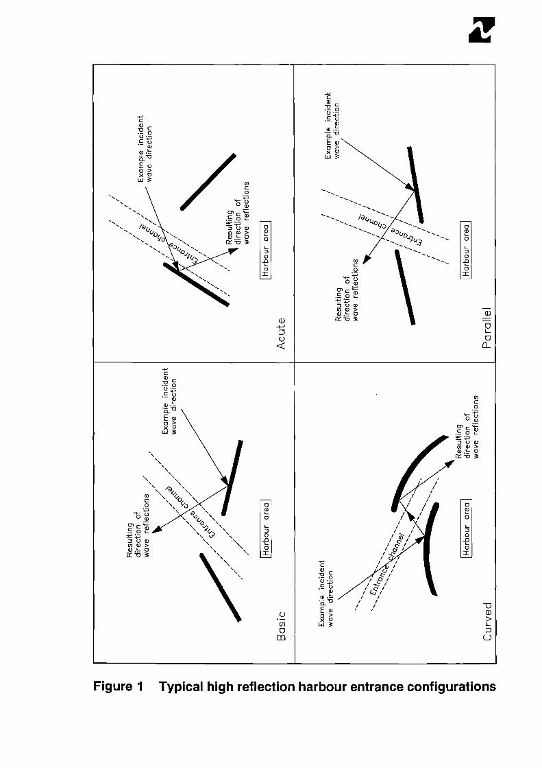
This work clearly shows that this type of problem exists in the UK and across Europe. This survey enabled the identification of four typical, high reflection harbour configurations where there was the potential for wave reflection problems at the harbour entrance, as shown in Figure 1. These configurations were used in a series of computational and physical model tests studies and are described in Chapter 2.
1.3 Navigational considerations The variability of wave activity at a harbour entrance which suffers from wave reflection problems will have a significant effect on vessel navigation, and it is this aspect which is considered, in general terms, in this section. The randomness of waves in nature leads to a wide range of frequencies being available to influence vessels at a harbour entrance. Generally, short period waves will have more effect on smaller craft, such as yachts, and longer period waves will have more influence on larger ships. For small harbours, such as marinas or fishing harbours one commonly encountered method of constructing the entrance channel is to build vertical sided retaining walls, forming a narrow channel leading to the main mooring area. Sometimes the entrance channel is open directly to the sea, while in other harbours there is some form of breakwater, sometimes very close to the retaining walls. The reasons for building the entrance channel in this way are concerned largely with cost. Vertical walls can be simply constructed from sheet piling, or concrete, stone or sometimes wooden faced walls.
Recently there has been a marked tendency for ports to attract the largest ships which can enter safely. These are often of a size such that their beam is a large proportion of the width of the entrance channel. In this case in severe wave activity it may be impossible, or very dangerous, for the ship to enter. Often the beam of the ship is up to 25% or more of the width of the channel, leaving perhaps five metres total clearance. If the ship is trying to enter in a heavy following or quartering sea, it may be unable to control its lateral lposition with sufficient accuracy to make the entrance without the risk of damage.
For larger vessels with long period waves it is possible for the wave frequency to approach the natural period of any of the ship movements. In this case, a condition of resonance will result, leading to large amplitude movements, which can cause loss of steerage and other manoeuvring difficulties. Furthermore, waves can give rise to set-up of the mean water level on the exposed side of the ship. The pressure difference that results can cause the ship to drift, in a similar way to the effect of wind forces. This can also cause manoeuvring difficulties, especially if the ship requires tugs, as they will have problems attaching to the ship and the dr i i will reduce their pulling efficiency.
It can also be appreciated that if the ship is subjected to a short crested sea, ie. consisting of multi-directional waves, due the interaction of incident waves and those reflected from, say, a vertical structure, then instantaneous forces and moments will be exerted on the ship in an unexpected way. This research has shown that this can be especially severe within three wave lengths from a reflective structure, where the sea steepness is rapidly changing due to wave reflections. This can lead to navigational difficulties especially at the slow speeds required in and around harbour entrances.
2 Summary studies
A series of computational and physic~l model studies were carried out to examine the methods to reduce the problems of wave reflections at harbour entrances. These are described in this chapter and consisted of the computational modelling of wave distu~rbance and porous wave screens, and the physical modelling of low reflection structures and entrance configurations. The methods and data generated by these studies can be used to determine the most appropriate means for ameliorating problems associated with wave reflections.
2.1 Computational modelling of wave disturbance This section contains a summary of the results obtained from a computational model study using the HR wave disturbance model, PORTRAY. This model uses a ray tracing method to calculate the height of storm and swell waves inside and around a harbour, for a given initial wave condition. In this model, rays, which are lines perpendicular to wave crests, are traced from a location offshore to the harbour entrance, and then inshore, in the direction of wave travel. The model includes the effects of wave diffraction around breakwaters, depth refraction and reflections from harbour boundaries.
The PORTRAY model was used to examine the four typical, high reflection harbour entrance configurations which were identified from the harbour survey, as described in Section 1.2. Each arrangement was tested to examine both the harbour entrance configurations and the changes in the reflection coefficients of vertical walls forming the entrance. The four harbour entrance arrangements are shown in Figure 1. This also highlights the potential wave reflection direction, across the harbour entrance, for each layout. The labelling of these configurations is based on the initial layout, referred to as the basic entrance, which was identified during the pilot study (McBride et al (1993)). This was constructed with the specific conditions and considerations of a range of individual UK harbours in mind. The final arrangement has the following characteristics:
- entrance formed from two vertically faced breakwater arms - entrance orientation away from the most severe wave direction - as the inclination and overlapping of the breakwaters forming the
entrance varies widely from harbour to harbour, a typical arrangement was selected.
In order to examine a range of typical, high reflection arrangements, the basic layout was modified to produce the three other configurations, as follows:
- 'Typical acute' represents a more open harbour entrance. The breakwaters are constructed at a more acute angle to one another, when compared with the 'basic' layout. This can lead to wave reflection problems within the harbour entrance, as shown in Figure 1.
- 'Typical curved' depicts the 'basic' layout with curved breakwaters. Figure 1 shows that with an incident wave direction a 90" to the entrance, a greater level of wave reflection may occur in the harbour entrance channel, than that of the 'basic' layout.

- 'Typical parallel' characterises an entrance where the breakwaters are approximately parallel to each other. This can lead to increased wave reflection activity in the entrance area, when compared with the 'basic' layout.
The pilot study report (McBride et al (1993)) provided a description of the PORTRAY modelling that was carried out on the basic layout. This study demonstrated that by modifying the reflection behaviour of the breakwaters forming the harbour entrance, the level of wave activity in the approach to the harbour can be reduced significantly. This effect was most marked during severe storm conditions which is when problems in entering the harbour are usually encountered.
The other three configurations were also tested, based on a range of wave conditions and potential modifications to the harbour entrance structures, based on UK harbours with similar entrance characteristics. These tests found that, generally, the most significant improvements in wave conditions in the entrance were achieved through modification of the vertical structures to reduce the level of wave reflections from them. In each case various configuration changes were attempted to aid the process of reducing wave reflections, however, these were constrained by natural features and estimated cost implications. These tests identified that modification of vertical structures to reduce their reflective characteristics was the most effective method for improving wave conditions at these types of harbour entrance.
2.2 Computational modelling of porous wave screens 2.2.1 The computational model A computational model has been developed to enable the prediction of reflection and transmission coefficients of a porous, vertical structure, with or without a solid backing wall. This model, BARRIER2, was developed at HR Wallingford in conjunction with the Department of Mathematics and Statistics of Brunel University. This model was initially validated against the results of a 1 : l5 scale physical model study of a proposed wave screen at Plymouth. A detailed description of this model and its initial validation is given by Bennett et al (1992).
The model uses inviscid linearised theory to describe flow either side of the porous front screen, with the application of matching conditions at the screen based on continuity of horizontal velocity, and a pressure jump condition to examine the flow through the holes in the screen. This theory resulted in the development of a non-linear integral equation for the horizontal velocity over the water depth, based on the theory of Mei et al (1974). In this work a quadratic-loss term is used with a head-loss, or discharge coefficient, C,. Mei's th~eory enables a value for this coefficient to be estimated directly from an empirical formula, related to the porosity, n,, of a wave screen with vertical slots, as follows:
This was considered to be a significant advancement for the use of models based on this theory, as in previous use, values of this coefficient were only able to be determined by experiment, which led to unreliable estimates when appropriate data were not available.

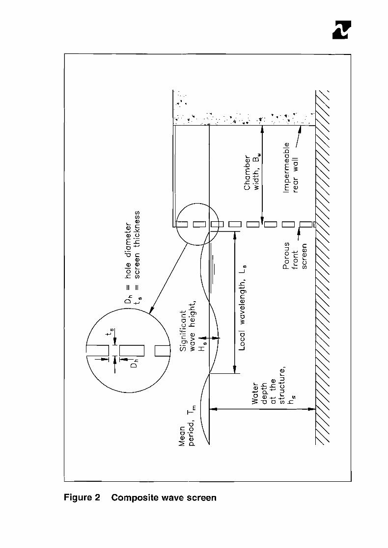
The computational model BARRIER2 was created from a simple computational model (BARRIER) which was developed to examine the reflection and transmission performance of a single porous vertical structure. The BARRIER2 model was extended to enable it to be applied to a composite wave screen, ie. a single wave screen with an impermeable backing wall, as shown in Figure 2. This was carried out by restricting the fluid domain between the screen and the backing wrall and modifying the expansion of the velocity potential. This led to an integral equation of the same form as that for the single porous screen. However, it must be accepted that the application of this theory to a composite wave screen does not allow explicitly for the effects arising from wave collisions or \riscous effects around the front screen.
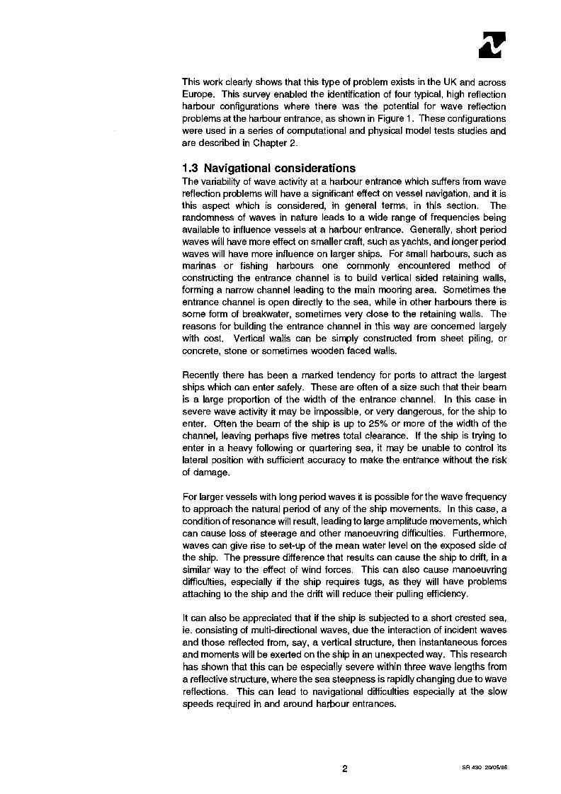
2.2.2 Application of the model Initial tests with BARRIER2 for a composite wave screen demonstrated, generally, the results expected from such a model. These are shown in Figure 3, where the reflection coefficient C, is plotted against the ratio of the porous screen spacing from the backin~g wall to the local wavelength, referred to as the relative chamber width, B jL,. Each set of data points relates to a different front screen porosity, indicatd on the figure. This shows that the lowest reflection coefficients occur at B j 4 of approximately 0.25 and 0.75, while highest reflections would be expected at B j L , of 0.5 and 1.0. It is interesting to note the very low values of C, predicted by the model for B j L , near to 0.25. At this off-resonance condition, the reflected wave crest is expected to collide with the next incident trough at the front screen. The highly non-linear and viscous flows resulting from these collisions are not represented by the model, and consequently the model over-predicts the energy loss, leading to the prediction of a lower than expected reflection coefficient. It is not expected that this effect would be so marked in a prototype structure.
2.2.3 Summary of results This study found that this model can be used to provide a good first estimate of the reflection and transmission coefficients of a single, porous, vertical screen in waves. It also found that ttie application of this model to a single wave screen can be applied to simulate a skirt breakwater, ie. a porous wave screen which does not extend to the seabed.
The computational model can also be applied to the composite wave screen arrangement, ie. a porous front screen with an impermeable rear wall. The model was calibrated against physical1 model data to provide a first estimate of the reflection coefficient for the str~~ctural arrangements that were tested. This was carried out using the discharge coefficient to compensate for the unrealistically high energy losses which would be predicted by the model for this type of wave screen arrangement. This process was carried out for two physical model studies and a simple regression analysis was used to provide a formula for the predication of a suitable value of the discharge coefficient. However, the results show that, at present, this C, value selection process can not account for all of the combinatiorls of test conditions which were used. Hence, the selection of a suitable value of C, may require consideration to be given to the screen spacing and the local wavelength, in addition to the screen porosity.
A full description of this study can be found in McBride et al (1995).

2.3 Physical modelling of low reflection structures 2.3.1 Test methodology A 2D physical model study was initiated to examine the reflection and overtopping performance of various 'low reflection' structures under irregular wave attack. It is these types of structures which can be used in the modification or construction of port entrances to reduce wave reflections, and so improve conditions for vessel navigation.
Four main structure types were tested consisting of a smooth vertical wall, single and double chamber wave screens and rock armour slopes. Various arrangements of these structures were tested in a wave flume to identify optimu~n configurations.
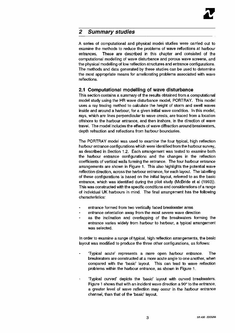
2.3.2 Discussion of results In terms of reflection performance, the study found that reflections from simple vertical walls generally fall close to C, = 0.90, but may be reduced by heavy overtop~ping. In general the larger and steeper waves lead to a slight reduction of reflections, due to higher levels of energy dissipation caused by wave breaking. However, an increase in the water level also lead to a reduction of reflections, but this was primarily due to the increased overtopping resulting from the lower structure freeboard, R,. This is illustrated in Figure 4 where it can be seen that values of C, are reduced at lower values of RJH,. A simple prediction method was created through the use of regression analysis on the upper and lower regions of this data. This enabled an upper bound and a simple equation to be applied to these resutts as follows:
C, = 0.79 + 0.1 1 RJH, for RJH, < 1 .O C, = 0.90 for RJH, > 1.0
The study also found that the use of single and double chamber wave screens are effective in reducing wave reflections and overtopping. The results of these tests followed the general trends identified previously by Allsop & McBride (1994), ie. the minimum value of C, is achieved when the porous screen is a little less than a quarter of a wave length from the solid wall, BJL, - 0.20 to 0.25. The previous work demonstrated that initial estimates of reflection performance can be achieved using numerical models such as 'BARRIER2' (see Section 2.2). However, it is clear from Section 2.2 that such models cannot describe the influence of many of the detailed modifications studied here, and that simple empirical methods may be more appropriate in some circumstances. These data have therefore been described by fitting a new empirical curve, given by:
where 16, k, and IJ. are coefficients determined from the data and:
k, determines the shape of the curve; low values (600) result in a shallow 'U' shaped curve, and high values (900) result in more steep 'v' shaped curves; specifies the value of BJL, which corresponds with the lowest point of the lowest value of C,;
IJ. gives the lowest value of C,.
The use of these test resutts allowed values of these coefficients to be established for each configuration. For example, Curve 1, the solid line shown

in Figure 5, describes the physical model results from the testing described in McBride et al (1995) and previous phy:sical modelling of a wave screen tested as part of work related to the Cardiiff Bay Barrage scheme. These data represent a single chamber wave screen, shown as points on Figure 5, with a porostty n, = 20% and a hole diameter equal to the screen thickness (which in the modelling work described by McBride et al (1995) was 25mm):
C, = sin { 910 [ (B JL,) - 0.225 l2 ) + 0.28 (4)
This equation is valid 0.05 c B J4 c 0.32. The use of equation (4) outside this range is not supported by the results considered here, although its use for 0 c B JL, c 0.05 will probably give reasonable results. There is, however, seldom need for details of reflection performance outside of these limits as such structures will be uneconomic, olr ineffective.
The modelling of the other structu~ral variations enabled values of the coefficients in equation (3) to be established for different structural configurations. These are presented iin Table 1.
The optimum diameter of circular holtss in the porous front screen was also identified as the thickness of the screen. The use of larger holes, with a diameter equal to twice the screen thickness, was found to lead to a slight degradation in reflection performance.
In addition, small changes in water level were found to have an insignificant effect on the reflective performance of single or double chamber wave screens, provided that the chambers did not alter significantly over the water level range. The use of part-depth chambers increased reflections significantly, particularly at lower relative water levels.
Reflections from simple armoured slolpes are generally well-predicted by:
except where the armour crest is relatively low. For configurations with the armoured crest below about AJD, = 1.3, reflections were found to increase significantly above those predicted by equation (5). However, this effect may be mitigated by providing a wider armlour crest, or in some circumstances by supporting the armoured slope on a part-depth caisson.
An analysis of the overtopping results showed that wave screens placed in front of a vertical wall significantly reduce the overtopping discharge, as well as reflections. The effect of the wave screens increases as RJH, or R* increases. Furthermore, the overtopping of a vertical structure protected by wave screens, or a perforated caisson, does not appear to be significantly affected by the addition of a second interference chamber, or wave screen.
Placement of an armoured slope in front of the vertical wall generally reduces overtopping, particularly at values of R* c 1 .l. When the structure freeboard is low, overtopping is close to that predicted for the simple vertical wall and an armoured slope. At lower water levels;, overtopping of the composite structure is lower than predicted for an armoured slope alone, and substantially lower than that predicted for the simple verh'ical wall.

2.3.3 Impact on wave conditions This study also developed a new technique to examine the effect of 'low reflection' structures on the sea surface. This was carried out through the analysis of local wave steepness. Previously a description of the reflection performlance and overtopping of a structure was used in the assessment of the likely effect of wave reflections, and hence the relative changes in wave height, on vessel navigation. However, vessel navigation problems are not only related to wave height as the wave period is also significant in the creation of hazardous conditions. This new technique enables both relative changes in wave height and wave period to be considered, allowing a better assessment on vessel navigation to be made.
This technique involves the determination of the wave steepness at key positior~s seaward of the harbour structures. The new parameter C,,, is defined as:
where t:he steepness is calculated as:
and sm(x) is the mean steepness at position 'x' metres from the structure
H,(x) is the significant wave height at position, 'X' metres from the structure
L, is the local wave length, calculated for the mean wave period measured at position 'X' and the still water depth at the probe position, using the Hunt (1979) approximation to the wave dispersion equation.
The incident steepness s,,(x) is calculated in the same way but refers to conditiolns without the structure in place, ie incident waves only.
An example of this type of analysis is presented in Figure 6. This shows a comparison of the relative steepness (Cstee,) from a simple vertical wall and one proltected by a perforated wave screen.
This analysis was used to show that at distances of greater than five wave lengths seaward of the structure, the ratio of relative wave steepness closely matches that expected for reflected wave heights. Further analysis of water surface conditions, ail distances of more than three wave lengths from the structur~e, demonstrated the potential benefits of the double chamber wave screen lover the single chamber version. The relative sea steepness results for the vertical wall at distances of less than three wave lengths seaward of the structur~e showed that rapidly changing wave steepness leads to very steep waves and frequent wave breaking (Figure 5). These conditions would be hazardous for small craft navigating in this region. A summary of the C,,, results for a vertical wall, single and double chamber wave screens, and a rock slope protected vertical wall are shown in Table 2. This shows the increasing level of protection from wave reflection effects provided by each of these structurisl modifications.
A full description of this study can be found in McBride et al (1995b).
2.4 Physical modelling of entlrance configurations This study was initiated to examine the reflection performance of various 'low reflection' structures under irregular wiwe attack from 15" and 30" incidence. It is these types of structures which1 can be used in the modification or construction of port entrances to reduce wave reflections, and so improve conditions for vessel navigation.
Three main structures were tested based on the 'basic' and parallel harbour entrance configurations The first and .second arrangements consisted of the basic configuration, where the seaward breakwater arms were constructed at angles of 15" and 30" to the incident \wave direction, respectively. The third arrangement was based on the parallel configuration, with the seaward structure at 15" to the incident wave di~rection. Initially each configuration was tested with the structures representing smooth vertical walls. The structures were subsequently modified to test single chamber wave screens and rock armour slopes.
The study found that the angle of wave incidence, from 0" to 30°, has little influence on the reflection coefficient of a plain vertical wall. It also found that the use of single chamber wave screens are effective in reducing wave reflections whilst keeping the vertical1 nature of the structure. From the analysis of these results, it was found that the empirical formula, which was previously derived during the 2D model tests, as described in Section 2.4, can be used to describe the reflection performance of such structures for the angles of wave incidence from 0" to 30°, within practical engineering limits.
The water surface condition analysis (sea steepness analysis), developed as part of the 2D model studies and dlescribed in Section 2.4 was used to demonstrate that for wave incidence angles of up to 30°, the reductions in both the reflected wave energy and in the level of relative wave steepness which can be achieved through the use of a rock armour slope, or, for circumstances where the vertical nature of the structure must be maintained, a single chamber wave screen, are significant. As with the 2D model tests, the relative sea steepness results for the vertical wall at distances of less than three wave lengths seaward of the structure showed that rapidly changing wave steepness leads to very steep waves and frequent wave breaking. These conditions would be hazardous for small craft navigating in this region, with incident wave directions of between 0" and 30".
A full description of this study can be found in McBride et al (1 996).
2.5 Application of the study results The preceding sections summarises the results of computational and physical model studies which were conducted to quantify the performance of low reflection structures for use at harbour entrances. The results from the studies can also be used directly in the engineering design of such structures as follows:
- Computational models of wave disturbance can be used for existing harbours to quantify and understand the sources of problems associated with wave reflections. This type of modelling can be used to isolate particular components of wave disturbance and could, for example, identify the particular area of a harbour wall which leads to high reflections at the entrance. For a new harbour, wave disturbance modelling can be used to examine the proposed design and identify at
arl early stage those parts of the layout that require modification. The model can then be used to confirm that structured andlor layout m~odifications achieve the objective of reducing reflections.
- The BARRIER2 model can be used to provide a first estimate of the reflection and transmission performance of either single porus wave screen or such a screen with a backing wall. This will provide the engineer with a good indication of the type of wave screen that is re~quired to achieve a stated level of reflection performance.
- The results from the 2D physical model tests have produced empirical fo~rmulae which can be used to determine the reflection performance of particular screen types and rock armoured slopes. These formulae can be! used by the engineer to assess the performance of particular low relflection structures during the design process.
- The results from the 2D and 3D tests have lead to the definition of the C,,, parameter which can be used to assess the impact of any changes in reflection performance on navigation. The C,,,, parameter is easily derived and provides the engineer with a direct method for quantifying the impact of changes in reflection performance on sea state and hence vessel navigation.
3 Guidance for design in existing harbours
3.1 Establish understanding of the problem The first stage in determining amelioration measures for harbour entrances which experience problems with wave reflections is to establish the structure, combiniation of structures, or element of a structure, from which the problem arises. This is important as vertically faced structures are often designed to protect 'the inner harbour areas from wave activity, and it is wave reflection that is one of the mechanisms which reduces the amount of wave energy entering the harbour. It is also necessary to correctly identify the incident wave directions and severity of wave activity which can lead to problems. In some cases il: has been found that one of the least severe wave directions would lead to serious navigation problems related to wave reflections. This occurred because the harbour entrance was primarily designed to prevent wave penetration of the harbour from the most severe wave directions.
Identification of wave reflection problems can be carried out using a number of methlods. However, it is recommended that the following approach is used:
- Detailed information gathering from the site, including anecdotal evidence from pilots and or port users, and a preliminary study of wave conditions.
- Computational modelling of the site to enable the level of wave reflections and an examination of the relative sea steepness close to the structure, or in the navigation channel at the entrance.
This method will ensure that all aspects of the problem, including the main causes are correctly identified. This method will also enable initial investigations of potential solutions, which may take the form of changes in
the entrance configuration to alleviate problem through the re-direction of wave reflections, or re-alignment of the entrance channel.
Alternatively, it may be possible andlor more practical to modify the reflective harbour structure to reduce the level of wave reflection, and hence alleviate the problem. This type of solution is discussed in the following section of this report.
3.2 Modification of existing vertical structures As discussed in McBride et al (1993), the advantages of vertical face structures over those with sloping faces lie in the efficient use of space, economy of construction material, and the abilrty to moor vessels alongside. In general the reflection performance of vertically or near-vertically faced walls will be described by a value of C, of between 0.9 and 1 .O. Problems due to the reflections from solid vertical faces suggests that an alternative form of construction should be considered, such as the provision of voids within the structure in order to dissipated wave energy, and hence reduce the level of wave reflection. Voids within which wave energy will be dissipated may be built into the structure as a pre-determined feature of the design. This can be achieved using wave screens, caissons, or by incorporating specially shaped concrete wall units having their own built-in voids.
The work reported in McBride et al(1!395,1995b and 1996) and summarised in Sections 2.2 and 2.3 can be used to determine the reflection performance of the various types of structure.
The following sections describes same examples of these potential 'low reflection' structure modifications.
3.2.1 Rock slopes The reflection performance of existing walls may be significantly improved by forming a mound against the seaward face of the wall, consisting of rock armour, as shown in Figure 7. This type of structure also has the benefit of providing the best protection from rapidly changing sea steepness close to the structure, as described in McBride et all (1 995b and 1996). However, it should be noted that this measure, whilst generally effective in reducing wave reflections, may increase wave overtopping under particular combinations of armour crest and water levels. This method will also create a structure that is not vertically faced, preventing rr~oring of vessels and increasing the structural and manoeuvring area requirements around the structure.
3.2.2 Perforated screens/cai,ssons The simplest wave absohing vertical walls used in harbours are single or multiple wave screen arrangements. As described in McBride et al (1993), these are formed of closely spaced etlements such as steel or timber piles, concrete or timber planks, or other pre-cast concrete elements. The screen elements are generally supported on a1 steel or timber pile structure. This may allow the provision of two or more screens on the same structure.
As previously discussed, the simplest multiple screen in general use incorporates a perforated front screen separated from a solid rear screen by a spacing B. For B equal to around 0.25 of the local wavelength L,, waves transmitted through the front screen will reflect off the rear screen to return towards the front screen out of phase with the next wave. The resulting interference leads to significant dissip~ation of wave energy between the two
screens, and hence yields particularly low reflections. For wavelengths other than the optimum, the reflection performance will be reduced. Laboratory testing1 of wave screens at HR Wallingford has generally shown that lowest values of C, are given by B/$ = 0.15 to 0.25. By judicious choice of screen porosiity n,, often between 10 and 25%, and screen spacing B, reasonable reflectiion performance may be obtained over a corresponding range of wavelengths, or wave periods.
Caisson~s with a perforated seaward face will incorporate at least two chambers, one open to wave induced flow through the perforated front face, the other, filled with sand, rock or concrete to ensure adequate resistance to sliding or overturning. The front face may be perforated by horizontal or vertical slots, or by circular holes. The width of the interference chamber should1 again be about 0.15 to 0.25 of the local wavelength. Wave absohing caisson breakwaters designs are described by Tanimoto & Goda (1 991a and 1991 b).
3.2.3 Relieving platforms A piled relieving platform may be used for vessel mooring and cargo handling operatialns where wave reflections are of concern. It is constructed from a piled qluay over a rock armoured, or natural slope, as shown in Figure 8. This type of structure is widely used where rubble mound construction OS
particularly economical, or where low reflections are essential. The example , shown in Figure 8 shows a part depth application of this type of construction. (Allsop ((1 995)).
3.2.4 Confirmation of effect of proposed modification Once a :suitable modification to ameliorate reflection problems at a harbour has been iidentified, these should be examined using either computational or physical models of wave distuhance. The results from these models will allow values cbf C,, in and around the entrance to be determined both without and with the modification in place to be calibrated. Comparison of the C, values, see for example Figure 6, will allow a direct evaluation of the benefits of the modificc~tion in terms of its impact on wave conditions and consequently navigalilon.
4 Guidance for design in new harbours
It is presumed that a full examination of the local topography of the proposed hahour site will be carried out as part of the investigation of other site specific issues. These must include investigations of the orientation of proposed hahour entrance and entrance structures to the principal wave directions. Conside!ration must also be given to other less severe wave directions to examine the likely directions and level of wave reflections, where the incident wave conditions would not usually be considered problematic. It is essential that this stage is carried out to ensure that wave reflection problems will not occur dlue to the interaction of reflected and incident wave conditions, particu~larly in vessel manoeuvring areas. This investigation must also include an assessment of the relative sea steepness conditions on the seaward side of any v'ertical hahour structure, to ensure safe navigation, within the hahour entrance, and in the approaches to the hahour.
Careful assessment of the proposed entrance and its use is also necessary. Consideration must be given to the likely vessels sizes, types and their manoeuvring characteristics in order that sufficient provisions are taken for safe and efficient operations, in terms of:
- The required manoeuvring space for the proposed operations - The extent of dredging to ensure sufficient channel depth, based on the
likely manoeuvring limits and the predicted environmental conditions - Protection of vessel manoeuvring areas from wave reflections, and
rapidly changing sea steepness.
If there is any doubt about the safety of proposed operation, then model studies should be undertaken to refine the design and ensure vessel safety.
Where applicable, consideration shou~ld be given to the use of rock slopes, perforated wave screens or caissons; as methods of protection from wave reflections during the iniitial design. Tlheir use should be considered in areas where wave reflections from proposed \~ertical walls may cause navigation or other problems.
5 Acknowledgements
The work described in this report is balsed on work completed by members of the Ports and Estuaries, and Coas1:al Groups of HR Wallingford for the Construction Directorate of the Depa~tment of Environment, under research contracts PECD 7161298 and 7161312,, and the Department of Transport. A nurnber of aspects of the testing and analysis was supported by the European Community MAST ll programme, under Sub-task 4.3 of the MCS project, and the University of Sheffield.

Allsop N.W.H. (1995) "Vertical walls and breakwaters: optimization to improve vessel safety and wave disturbance by reducing wave reflections" Chapter 10 in Wave Forces on Inclined and Vertical Wall Structures, ed. Kobayashi N. & Demirbilek Z., ASCE, New York, 1995.
all sop^ 1N.W.H. & McBride M.W. (1 994) "Reflections from vertical walls: the potential for improvement in vessel safety and wave disturbance" Proceedings of International Workshop on Wave Barriers in Deepwaters, Port and Harbour Research Institute, Yokosuka, Japan, 10-1 4 January 1994, pp1 01 -1 28.
Bennetl: G.S., Mclver P., & Smallman J.V. (1992) "A mathematical model of a slottetl wave screen breakwater" Coastal Engineering, Volume 18, Elsevier, 1992.
McBride M.W., Hamer B.A., Besley P., Smallman J.V. & Allsop N.W.H. (1993) "The hydraulic design of harbour entrances: a pilot study" Report SR 338, HR Wallingford, April 1993.
McBride M.W., Smallman J.V. & Allsop N.W.H. (1994) "Design of harbour entrances: breakwater design and vessel safety" Proceedings of Hydro-port '94, Po~lt and Harbou~r Research Institute, Yokosuka, Japan, 19-21 October 1994, pp525-541.
McBride M.W., Smallman J.V. & Allsop N.W.H. (1995) "Vertical walls and low ref lectio~n alternatives: numerical modelling of absorbing wave screens" Report IT 400, HR Wallingford, April 1995.
McBride M.W., Allsop N.W.H., Besley P., Colombo D., L Madurini (1995b) "Vertic:al walls and low reflection alternatives : Results of wave flume tests" Report IT 41 7, HR Wallingford, April 1995.
McBride M.W., Smallman J.V. & Allsop N.W.H. (1996) "Guidelines for the hydraulic design of harbour entrances" Report SR 430, HR Wallingford, February 1996.
Mei C,.C:., Liu P.L. & lppen A.T. (1974) "Quadratic loss and scattering of long waves" Journal of the Waterways, Harbours and Coastal Engineering Division, ASCE, 'Volume 100, No. WW3, August 1974.
Tanimoita K. & Goda Y. (1991a) "Historical development of breakwater structures in the world" Conference Proceedings, Coastal structures and Breah~iaters, London, ICE, Thomas TeHord, 1991.
Tanimota K. & Goda Y. (1 991 b) "Stability of deep water caisson breakwater against random waves" Conference Proceedings, Coastal structures and Breah~iaters, London, ICE, Thomas TeHord, 1991.


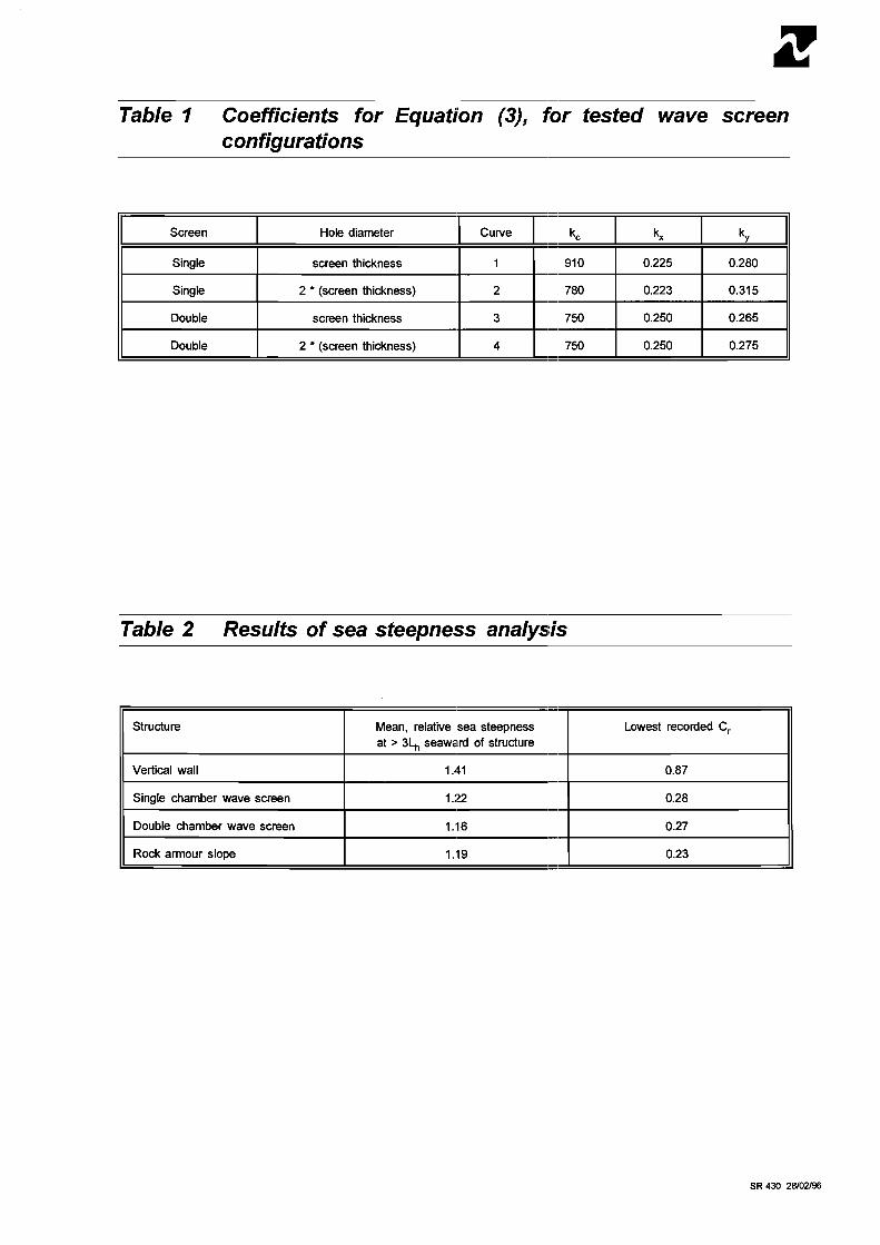
Table 1 Coefficients for Equati'on (3), for tested wave screen configurations
Screen
Single
Single
Double
Table 2 Results of sea steepness ana1ys:is
Double
Structure I Mean, relative sea steepness I Lowest recorded C,
Hole diameter
screen thickness
2 ' (screen thickness)
screen thickness
at > 3L, seaward of structure - I I
- 2 (screen thickness)
Vertical wall I 1.41 I 0.87
Curve
1
2
3
Single chamber wave screen
0.225 0.280
0.223 0.31 5
0.250 0.265
4
Double chamber wave screen I 1.16 I 0.27
Rock armour slope I 1.19 I 0.23
750 0.250 0.275


r 7 < CD n
I I I I I I
s am 0 ?(D < (D 0 moc
CA ;oy 5 =a m0
0 -
sax
.
<l= --. m -7
Dh
=
ho
le
dia
me
ter
t,
=
scre
en
th
ickn
ess
/
..
.
.A
:.
. 1
..
M
ecn
Sig
nif
ica
nt
'I
.
".
pe
rio
d,
T, . e.
wav
e h
eig
ht,
1'
l ' .
. $
. 1
. . . .
Lo
cal
wav
elen
gth,
L,

Reflection coefficient, Cr

-
-
-
-
I 1 I 7 S m LT, m m
m - 0
0 Cl
0 0
0
m m
m
m - . N E
m CU
0 I I
9
N 2 + -. -tJ c ,- a, c 4 cn E a, CU
- - L U 0
I I a, cn > I
,-
p " a, + U
7
m - 0
0
13 'lua 13 I j jam uo I pa 1 jai
Figure 4 Influence of relative crest height on reflections


( ) wsl(x)ws 'ssaudaals eas U I a6u43 a n j l e 1 ad
Figure 6 Comparison of relative wave steepness between simple vertical wall and composite wave screen
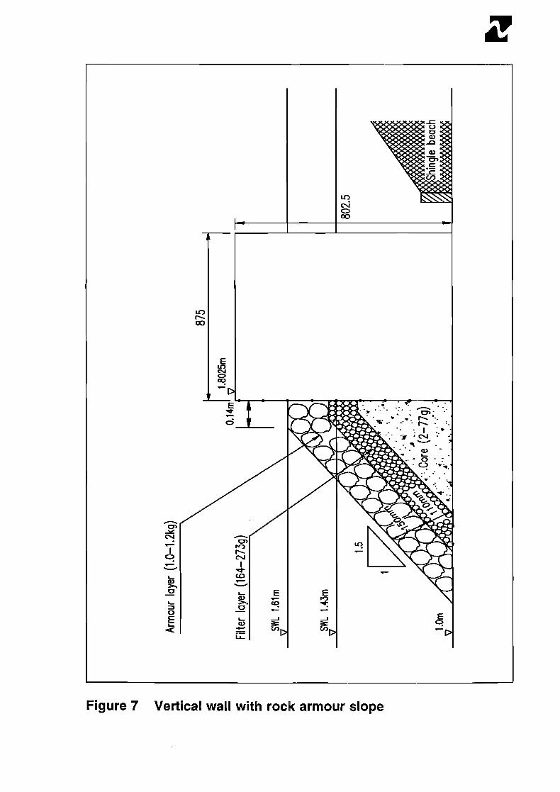

Figure 8 Piled relieving platform over armoured slope


'I & HR Wallingford
Our ref: PIE1214
31 January 1995
FOR THE ATTENTION OF THE HARBOUR ENGINEER
Dear Sir
RESEARCH INTO WAVE REFLECTIONS AT AND AROUND PORT ENTRANCES
HR Wallingford is carrying out research into the hydraulic design of harbour entrances. The project aims to produce guidelines to aid engineers in the design of harbour entrances, specifically with regard to the use of vertical or near vertically faced structures. This work is being carried out to aid in the requirements of a number of projects on behalf of PlANC PTC II Working Group 28, the UK Department of the Environment and the Monolithic Coastal Structures project, supported by EC MAST II.
As part of this project we are carrying out a survey of selected UK harbours and we would be most grateful if you could complete the enclosed questionnaire. The information collected will be used to quantrfy the extent and nature of problems to navigation at and around harbour entrances. It will subsequently be used to aid in the refinement of a three dimensional physical model study. This study will test a series of harbour entrance configurations in a wide variety of wave conditions to examine the effects of wave reflections. All site specific information supplied will be treated in confidence and will only be quoted outside the project with the permission of the group or groups involved.
The result of this research work will take the form of a series of guidelines for port engineers. This will enable the effect of wave reflections on vessel navigation to be considered during the design of port structures. It will also offer methods of reducing wave reflections, where the use of vertical or near vertically faced walls is preferred.
This analysis of the questionnaires is scheduled to be completed before the end of February 1995 and hence we would greatly appreciate the return of the completed questionnaire, by post, in the enclosed self addressed envelope or by fax, before Friday 17 February.
Experience from the work carried out in Spain, on behalf of PIANC Working Group 28, suggests that this questionnaire should take no longer than 1 hour to complete. If required. I could arrange to visit you to assist with the completion of the questionnaire and to answer any concerns or queries.
We greatly appreciate your participation in this work. Your contribuuion will be fully acknowledged and you will of course, be sent a early copy of the final report to ensure that you will benefit from your contribution, in any future design studies.
Again thank you for your help.
Yours faithfully
Dr Mark W McBride Project Manager. Ports and Estuaries Group
Address and Registered Office: H R Wallingford Ltd, Howbery Park. Wallingford, Oxon O X I 0 BBA, UK
Tel: +44 (0)1491 835381 Fax: +44 (0)1491 832233
Registered in England No 2562099. HR Wallingford Lrd is a wholly owned subsidiary of HR Wallingford Group Lcd

Hydraulic design of harbour entrances
Survey of Ports and Harbours
Background
HR Wallingford is carrying out research into the hydraulic design of harbour entrances. This project aims to produce guidelines to aid engineers in the design of harbour entrances, specifically with regard to the use of vertical or near vertically faced structures. This work is being carried out to aid in the requirements of a number of projects on behalf of PlANC PTC II Working Group 28, the UK Department of the Environment and the Monolithic Coastal Structures project, supported by EC MAST II.
Justification
A study by McBride et al (Ref 1) identified that vessels entering certain ports in the UK can experience manoeuvring difficulties as a result of the interaction of incident waves and waves reflected from such structures, especially in severe weather conditions. The consequences of this type of problem may lead to a reduction in the confidence of a ship operator to use the port, resulting in potential losses in port revenue. The worst consequences, however, could be damage to vessels or port structures, loss of life or serious injury, environmental damage due to cargo spillage, andlor potential temporary port closure.
Under the work of PlANC Working Group 28 a survey of Spanish ports examined the problems of wave reflection in Spain. This study found that 50% of the ports investigated had problems associated with vessel entry due to wave reflections. In the majority of the ports affected, the difficulties required the use of additional tugs to ensure safe navigation of vessels. In one case, however, the interaction of incident and reflected waves caused the port to close for up to 10% annually.
Need for a Survey
The research at HR Wallingford has examined many aspects of the use of vertically faced structures, and has tested a selection of amelioration methods to reduce wave reflections (Ref 2). Particular attention has been given to those designed to retain the vertical nature of the structure and those which are designed to use the least amount of space. This is especially imporlant in ports where space is at a premium. For example, in an approach channel where the use of a rock slope may provide an adequate reduction in wave reflections, expensive dredging regimes may be required to maintain the channel width. The retention of the vertical nature of a structure may also be required for mooring purposes, without the additional expense of, for example, creating a piled jetty over a rock slope.
Having carried out a series of two dimensional physical model tests to quantify potential reductions of reflections, thus optimising newlmodified structures, the next stage is to carry out a series of three dimensional physical model tests. These tests will enable the effects of entrance configuration and varying wave direction to be taken into account. It is essential therefore, to examine several real harbour entrances where problems exist. This will ensure that the structures to be tested in the physical model are designed in a way that simulates real harbour design. It is for this reason that we are carrying out a survey of selected ports.
Aim of the Survey
The aim of the survey is to identify ports and harbours with vertical or significantly reflective structures forming their entrance, with problems concerning vessels navigating the entrance, especially in severe weather conditions. Those which can be identified, whose problems are a direct result of the interaction of incident and reflected waves, at or around the entrance to the harbour, are of particular interest.

Use of Information
The information collected will be used to quantify the extent and nature of problems to navigation at and around harbour entrances. It will subsequently be used to aid in the refinement of a three dimensional physical model study. This will be used to test a series of harbour entrance configurations in a wide variety of wave conditions to examine the effects of wave reflections.
Confidentiality
All site specific information supplied will be treated in confidence and will only be quoted outside the project with the permission of the group or groups involved.
References
1. McBride MW, Hamer BA, Besley P, Smallman JV & Allsop NWH. The hydraulic design of harbour entrances: a pilot study. Report SR338, HR Wallingford, April 1993.
2. Allsop NWH & McBride MW. Reflections from vertical walls: the potential for improvement in vessel safety. Paper 4.3 to ,the MAST I! MSC Project Workshop, Madrid, October 1993 and Proceedings of the International Workshop on Wave Barriers in Deepwaters, Port and Harbour Research Institute, Yokosuka, Japan, January 1994. pp1 01 -1 28.
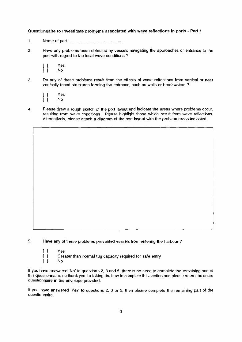
Questionnaire to investigate problems associated with wave reflections in ports - Part 1
1. Name of port .................................................
2. Have any problems been detected by vessels navigating the approaches or entrance to the port with regard to the local wave conditions ?
3. Do any of these problems result from the effects of wave reflections from vertical or near vertically faced structures forming the entrance, such as walls or breakwaters ?
4. Please draw a rough sketch of the port layout and indicate the areas where problems occur, resulting from wave conditions. Please highlight those which result from wave reflections. Alternatively, please attach a diagram of the port layout with the problem areas indicated.
5. Have any of these problems prevented vessels from entering the harbour ?
[ l yes [ ] Greater than normal tug capacity required for safe entry [ 1 No
If you have answered 'No' to questions 2, 3 and 5, there is no need to complete the remaining part of this questionnaire, so thank you for taking the time to complete this section and please return the entire questionnaire in the envelope provided.
If you have answered 'Yes' to questions 2, 3 or 5, then please complete the remaining part of the questionnaire.

Questionnaire to investigate problems associated with wave reflections in ports - Part 2
6 Structures forming the entrance
6.1 Please indicate the types of structures which form the harbour entrance. Select as many as are necessary:
Please tick (and supply other information where requested)
6.1 .l vertical walls [ 1 6.1.2 sloping walls [ ] slope ......... 6.1.3 rock armour slopes [ ] slope ......... berm width ......... berm level ........ 6.1.4 other breakwater units [ ] type ..................................................................... 6.1.5 other type of structures [ ] type .....................................................................
6.2 If the structure is a vertical or sloping wall, is it protected by a wave-screen or voided blockwork:
If yes, please speclfy the type of protection: ................................................................................. ...........................................................................................................................................................
6.3 Please sketch the alignment of the vertical or near vertical structures andfor the entrance to the most significant wave directions. Please pay particular attention to the alignment of the structures with respect to one another and the degree of overlap. Alternatively, please attach a diagram of the layout of the structures forming the port entrance.
6.4 Please indicate on the sketch of the entrance layout the percentage of wave reflection encountered, visually, as compared to the incident waves. For example, '1 00%' for reflected waves which are the same size as the incident waves, or '50%' for wave reflections of half the size of incident waves. Please also indicate the type of wave conditions resulting from wave reflections.

7 Information on port closures due to severe weather conditions over, at least, the previous two years
Please complete the following table to provide as much information as possible on port closures. Please start with the most recent closures and use copies of this page if there is not enough space.
If the wave conditions were not recorded accurately then please provide an approximate description using the following notation:
Description Wave height (m)
calm 0 - 0.3 light 0.3 - 1 .O moderate 1 .O - 2.0 heavy > 2.0

8 Vessels using the port
Please complete the following table to provide information on the dimensions of the key vessels using the port.
9 Additional information
9.1 If encountered, please describe the effect of wave reflections on moored ships within the harbour ........................................................................................................................................
9.2 Please provide any further comments, or problems not already described, concerning wave reflections in or around the port ..................................................................................................
vessel name
vessel type
length overall (m)
length between perpendiculars (m)
beam (m)
design draught (m)
deadweight (tonne)
displacement (tonne)
number of propellers
bow thruster ?
Smallest vessel or vessel type using the port
Most frequent vessel or vessel type using the port
Characteristics
9.3 Please estimate the number of ship related incidents which have taken place in the harbour or the approaches, over the previous five years, as follows:
Vessel or vessel type most affected by wave reflections
Largest 'vessel or vessel type using the port
vessel groundings
ship-ship collisions
ship-port structure collisions
loss of controlldrifting
Those due to bad weather conditions, idaround the harbour entrance
Total Those inlaround the harbour entrance