guide to dual flight operations - national weather … html/guide to dual flight...the rrs helpline...
TRANSCRIPT
Guide to Dual Flight Operations:
Vaisala RS92-NGP Preparation and Performance
Data Continuity Study
Sterling Field Support Center
Attachment F
Vaisala RS92-NGP Preparation and Performance
• This familiarization is designed for observers who have taken the RRS certification test.
Covered Topics:
2
- RRS System Initialization - Radiosonde Preparation and Handling - Baselining and GPS lock -Launching the Radiosonde - Quality controlling after release - Editing the Coded Messages
- Archiving - Capture - Controlling the TRS Antenna - Multiple Releases - RRS Helpline Function

Vaisala RS92-NGP
• 1 = GPS Antenna
• 2 = Battery Housing
• 3 = Vaisala Radiosonde RS92-NGP
• 4 = Antenna, mailing bag inside
• 5 = Temperature Sensor
• 6 = Humidity Sensor
• 7 = Sensor Boom
• 8 = FSD25 Interface
• 9 = Additional Sensor Interface
3
Total Weight of Vaisala RS92-NGP: 305 grams

RRS System Initialization
• Start RWS and allow TRS to warm-up – Allow at least 30 minutes prior to baseline
• TRS Warm-up is dependent on ambient temperatures, but generally lasts between 10-30 minutes
• Initialization takes approximately 1 minute
• SPS requires ~15 minutes to establish the GPS almanac
– The TRS Status Line on the Antenna Orientation Display will indicate “TRS is ready” when warm-up and initialization is complete
4
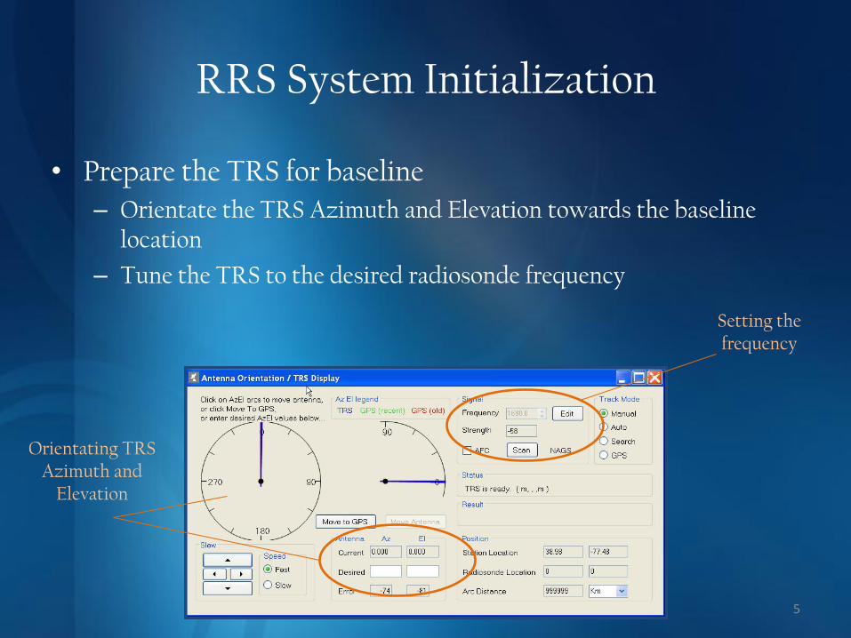
RRS System Initialization
• Prepare the TRS for baseline
– Orientate the TRS Azimuth and Elevation towards the baseline location
– Tune the TRS to the desired radiosonde frequency
5
Orientating TRS Azimuth and
Elevation
Setting the frequency

Radiosonde Preparation and Handling
6
• Carefully unpack the radiosonde and inspect for damage
• Record Serial Numbers
• Place on the Frequency Setting Device (FSD) to set the frequency and burn off contaminants
– Plug connector into radiosonde
– Turn on FSD power
– Select frequency channel
CH1= 1676 MHz CH2= 1678 MHz CH3= 1680 MHz CH4=1682 MHZ
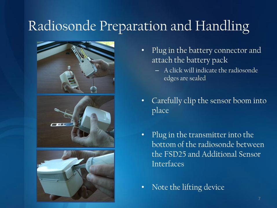
Radiosonde Preparation and Handling
7
• Plug in the battery connector and attach the battery pack – A click will indicate the radiosonde
edges are sealed
• Carefully clip the sensor boom into place
• Plug in the transmitter into the bottom of the radiosonde between the FSD25 and Additional Sensor Interfaces
• Note the lifting device

Baselining and GPS Lock
8
• Prior to Baselining – Ensure the TRS is orientated to the baseline position, tuned to the
correct frequency, and that the AFC is ON
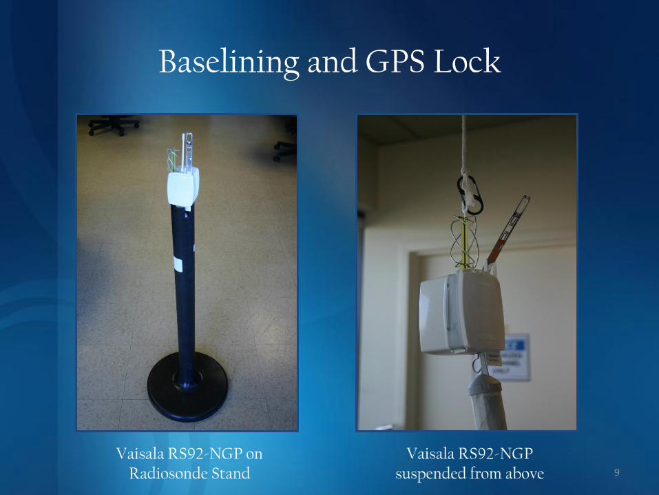
• Baseline Position – Radiosonde should be placed on a radiosonde stand or suspended from
above
– Do not place radiosonde on a solid surface as this may result in poor performance
– Place under or near the GPS repeater (repeater must be powered on)
– Observer MUST wait at least 5 minutes before accepting baseline. Time is needed for the sensors to stabilize and for a proper sensor correction to be calculated
• Failure to do so will result in a required termination
• A minimum of 4 satellite matches are required for GPS lock
Baselining and GPS Lock
9
Vaisala RS92-NGP on Radiosonde Stand
Vaisala RS92-NGP suspended from above
Baselining and GPS Lock
10
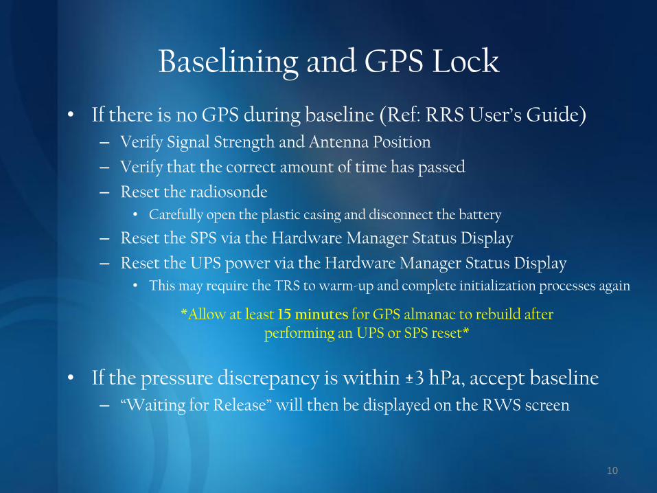
• If there is no GPS during baseline (Ref: RRS User’s Guide) – Verify Signal Strength and Antenna Position
– Verify that the correct amount of time has passed
– Reset the radiosonde
• Carefully open the plastic casing and disconnect the battery
– Reset the SPS via the Hardware Manager Status Display
– Reset the UPS power via the Hardware Manager Status Display
• This may require the TRS to warm-up and complete initialization processes again
*Allow at least 15 minutes for GPS almanac to rebuild after performing an UPS or SPS reset*
• If the pressure discrepancy is within ±3 hPa, accept baseline – “Waiting for Release” will then be displayed on the RWS screen
Baselining and GPS Lock
11
• For additional information and assistance
• FAQs Website
• http://ops13web.nws.noaa.gov/rrd/
• RRS Helpline
• (703) 661-1268

12
Take a Break..

Launching the Radiosonde
13
• Position the TRS before proceeding to the release site – Manual Track Mode
– Direct Azimuth and Elevation to where the radiosonde is expected to travel (downwind)
• After release, utilize the remote Control Display Unit (CDU) to track the radiosonde – Wide Angle Gathering System (100 °)
– Narrow Angle Gathering System (15 °)
14

0x0800 Errors
15

Quality Control After Release
16
• Ensure the TRS is tracking appropriately and that signal strength is acceptable – Place the Antenna into the Move to GPS mode only if GPS is available
• Selecting Move to GPS when GPS is not available may cause the software to freeze
– Monitor the Status Messages for any tracking notifications
• Update the Surface Observation and release time as necessary – For release time, check the first pressure data point below the red line in
the Received PTU Tabular Display • Should have a pressure less than or equal to the release pressure shown in the Surface
Observation
– Check the Geopotential Height and ensure it increases with time
– Verify the Cloud/Weather observation and ensure it’s accurate at release
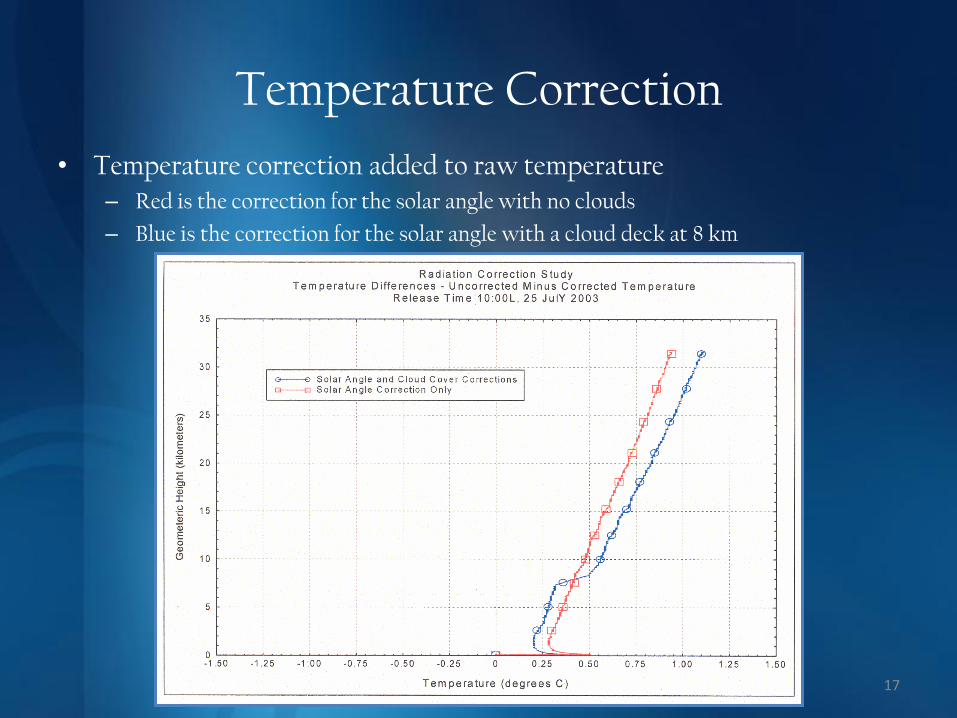
Temperature Correction
17
• Temperature correction added to raw temperature – Red is the correction for the solar angle with no clouds
– Blue is the correction for the solar angle with a cloud deck at 8 km

Quality Control After Release
18
• Marking & Editing Data – Verify data continuity from the
surface into flight
• Dry RH bias just off the surface
– Common data quality problems requiring attention
• “Wet-bulb effect”
• Noisy RH data
• Super-adiabatic lapse rates
– During flight, periodically check for anomalous data
• Plots
• Check Messages
Wet-bulb Effect
Noisy RH Data
Editing Coded Messages
19
• Once the Coded Messages are generated, review plots, Check Messages and Tabular data prior to transmission – If changes to the flight data are made, Coded Messages will need to be
recoded
• Edits made in the Processed Tabular Display
• Do not edit the body of the Coded Messages unless absolutely necessary – Necessary edits include:
• Adding appropriate 101 groups
• Adding appropriate Icing comments to RADAT
– Editing the message body will not affect the processed data
– Edits to the message body are not saved to the NCDC Archive file
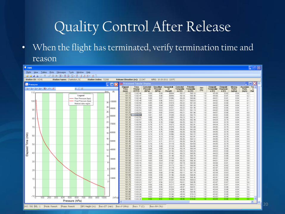
Quality Control After Release
20
• When the flight has terminated, verify termination time and reason

21
Take a Break..
Transmitting an Archived Flight
• In Utilities, select NCDC Archive Utilities – Select the flight to Archive
– Select “Build Archives and send to NCDC”
– Individual log files for each office can be found here:
• www1.ncdc.noaa.gov/pub/data/ua/RRS/2008/
22

23
1. Tools -> Utilities
2. NCDC Archive Utility
3. Build Archives and send to NCDC
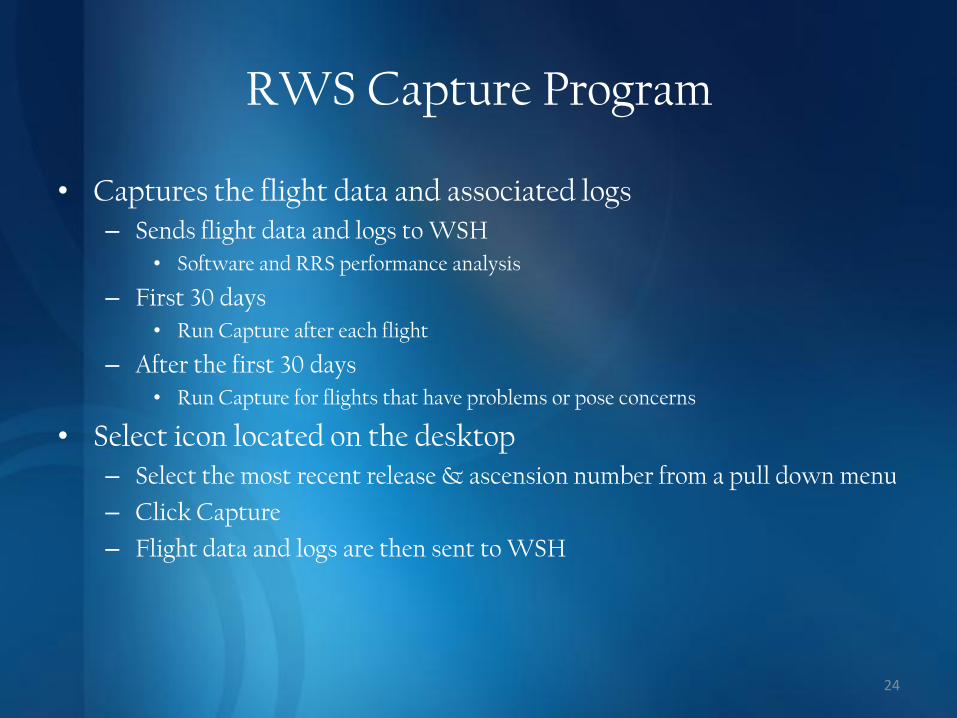
RWS Capture Program
• Captures the flight data and associated logs – Sends flight data and logs to WSH
• Software and RRS performance analysis
– First 30 days
• Run Capture after each flight
– After the first 30 days
• Run Capture for flights that have problems or pose concerns
• Select icon located on the desktop – Select the most recent release & ascension number from a pull down menu
– Click Capture
– Flight data and logs are then sent to WSH
24

Controlling the TRS Antenna
25 Remote Control Display Unit (RCDU)
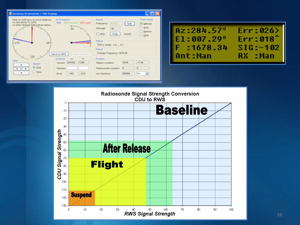
26

Second and Third Releases
• Leave UPS(TRS) ON after the first release
• Place the TRS in Manual
• Set the new radiosonde to a different frequency
• Set the TRS to the new frequency – Don’t Scan as this could cause the TRS
to lock onto the previous radiosonde
• Move TRS back to the baseline position
• After a successful flight, select the active release to Archive
27
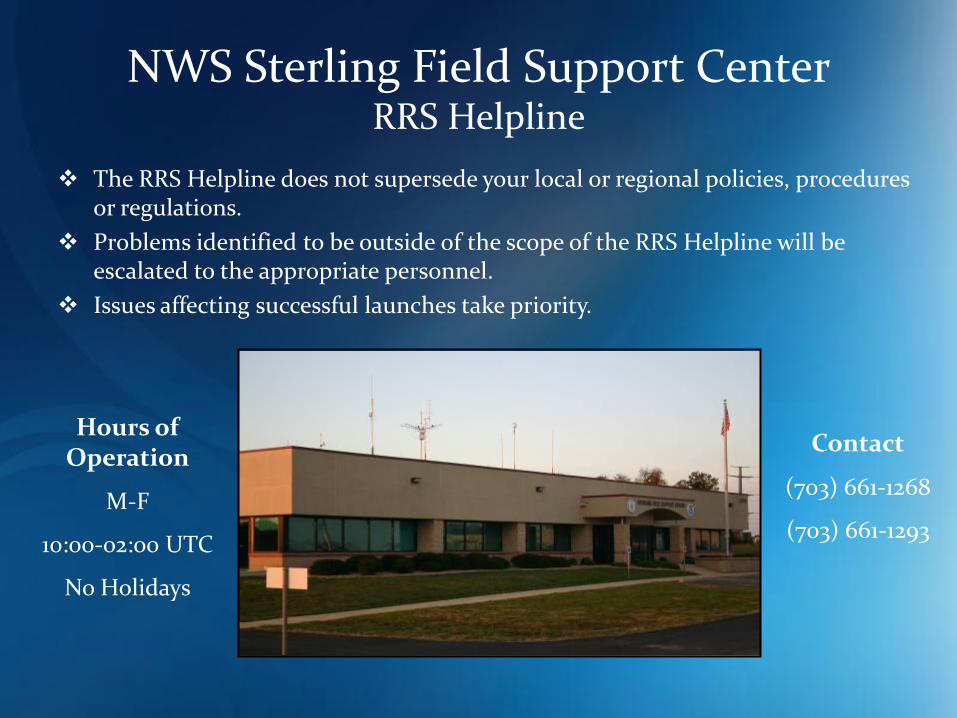
NWS Sterling Field Support Center RRS Helpline
The RRS Helpline does not supersede your local or regional policies, procedures or regulations.
Problems identified to be outside of the scope of the RRS Helpline will be escalated to the appropriate personnel.
Issues affecting successful launches take priority.
Hours of Operation
M-F
10:00-02:00 UTC
No Holidays
Contact
(703) 661-1268
(703) 661-1293