guidance manual for battery manufacturing pretreatment ... · pdf fileand the final...
TRANSCRIPT
&EPA
United States Environmental Protection Agency
Effluent Guidelines Division and Permits Division Washington DC 20460
Guidance Manual
August 1987
for Battery Manufacturing Pretreatment Standards
EPA 440/1-87/014
GUIDANCE MANUAL FOR
BATTERY MANUFACTURING PRETREATMENT STANDARDS
Prepared by the ·
Industrial Technology Division Office of Water Regulations and Standards
and Permits Division
Office of Water Enforcement and Permits
August 1987 Office of Water
u.s. Environmental Protection Agency 401 M Street, s.w.
Washington, D-G· 20460
ACKNOWLEDGEMENT
This document was prepared by .Science Applications International Corpora~ion (SAIC) and Whitescarver Associates under EPA Contract Nos. 68-01-6514, and 68-01-7043.
TABLE OF CONTENTS Page
1. INTRODUCTION . .................. • ..................... ct • • 1-1
1.1 HISTORY OF THE BATTERY MANUFACTURING CATEGORY ...•. 1-2
2. BATTERY MANUFACTURING CATEGORICAL STANDARDS ...•.•....•• 2-1
2 . 1 AFFECTED INDUSTRY. • • . . • . . • . . • . . . . . . . • . • • . • . • . • . . . . 2 -1 2. 2 PROCESS OPERATIONS. . • • . • • . . • . • • . . • . • . • . . . . • . • . • • . • 2-2 2. 3 SUBCATEGORIZATION. • . . . • . . . . . • . . • • • . . • . . . . • . . . • . . . • 2-3
2. 3 .1 Cadmium Subcategory. • • . . • • • . • • • • . . . . . . . • . . . 2-5 2.3.2 Calcium Subcategory ••..••••......•••....•.. 2-11 2. 3. 3 Lead Subcategory. . • . . • . . . . . . . . . . . . • • • . . • . . . 2-14 2.3.4 Leclanche Subcategory .•.......•.••.•••..... 2-17 2.3.5 Lithium Subcategory .•..•..•......•.•....... 2-20 2.3.6 Magnesium Subcategory ••••.•.••.••••.•....•. 2-23 2. 3 . 7 Zinc Subcategory ..• "• . • . . . . . • . • . • • • • . • • • • . . • 2-2 6
2.4 OPERATIONS COVERED UNDER OTHER CATEGORIES •.••..... 2-34 2.5 PRETREATMENT STANDARDS FOR THE BATTERY
MANUFACTURING CATEGORY .•• ~ ••..•••..••••••••••••••• 2-34 2.6 GUIDANCE FOR CONSIDERATION OF EMPLOYEE SHOWER
WASTEWATER AT LEAD SUBCATEGORY PLANTS .•..•...•..•. 2-36 2 • 7 COMPLIANCE DATES ..••••... ~ • • . . • • • . • • • . • • . • • • • • • • • • 2-41
3. TREATMENT TECHNOLOGIES• ••..•..• ~ . . • . . • . . . . • . . . . . . . . . . . • . 3-1
3.1 END-OF-PIPE TREATMENT TECHNOLOGIES •......•.••.•.•. 3-2 3.2 IN-PROCESS CONTROL TECHNOLOGIES ................... 3-4
4. REQUIREMENTS OF THE GENERAL PRETREATMENT REGULATIONS .... 4-1
4.1 INTRODUCTION ..............••........... " .......... 4-1 4.2 CATEGORY DETERMINATION REQUESTS .......•.•......•.• 4-2 4.3 MONITORING AND REPORTING REQUIREMENTS OF THE
GENERAL PRETREATMENT REGULATIONS ..••..•••..••..•.. 4-3 4.3.1 Baseline Monitoring Reports ....••• ~········ 4-3 4.3.2 Compliance Schedule Progress Report ........ 4-6 4. 3. 3 Report on Compliance....................... 4-6 4.3.4 Periodic Reports on Continued Compliance ... 4-7 4.3.5 Notice of Slug Loading .......•............. 4-7 4.3.6 Monitoring and Analysis to Demonstrate
Continued Compliance .............••..•••... 4-8 4.3.7 Signatory Requirements for Industrial
User Reports ...... ~ ........................ 4-8 4.3.8 Recordkeeping Requirements .•••..•....•..... 4-9
i
4.4 APPLICATION OF THE COMBINED WASTESTREAM FORMULA ••• 4-9 4.5 REMOVAL CREDITS ••••.••••••••••••••••••.••..••.•••• 4-12 4.6 FUNDAMENTALLY DIFFERENT FACTORS (FDF) VARIANCE •.•• 4-22 4.7 LOCAL LIMITS ...................................... 4-23
5. APPLICATION OF BATTERY MANUFACTURING CATEGORICAL PRETREATMENT STANDARDS • • • • . • • • • • • . • . . • • • . • • • • • . . . . • • • . . . 5-1
REFERENCES •••••••••••••••••••••••••••••••••••••••••••••••••• R-1
APPENDIX A
APPENDIX B
APPENDIX C
GLOSSARY OF TERMS
PSES AND PSNS FOR BATTERY MANUFACTURING SUBCATEGORIES
Subpart A: Cadmium PSES . . . . . . . . . . . . . . . . . . . . subpart C: Lead PSES . . . . . . . . . . . . . . . . . . . . . . . subpart D: Leclanche PSES . . . . . . . . . . . . . . . . . . Subpart F: Magnesium PSES . . . . . . . . . . . . . . . . . . subpart G: Zinc PSES . . . . . . . . . . . . . . . . . . . . . . . Subpart A: Cadmium PSNS . . . . . . . . . . . . . . . . . . . . Subpart B: Calcium PSNS . . . . . . . . . . . . . . . . . . . . Subpart C: Lead PSNS . . . . . . . . . . . . . . . . . . . . . . . Subpart D: Leclanche PSNS . . . . . . . . . . . . . . . . . . Subpart E: Lithium PSNS . . . . . . . . . . . . . . . . . . . . Subpart F: Magnesium PSNS . . . . . . . . . . . . . . . . . . Subpart G: Zinc PSNS . . . . . . . . . . . . . . . . . . . . . . . EPA AND STATE PRETREATMENT COORDINATORS
ii
B-1 B-2 B-3 B-3 B-3 B-6 B-7 B-7 B-8 B-8 B-8 B-9

'LIST OF TABLES.AND FIGURES
Table Page
2.1 BASIC DETERMINATIONS NEEDE.D TO APPLY BATTERY MANUFACTURING REGULATION ..........••.••.•••••••••• 2-6
'
2.2 CADMIUM SUBCATEGORY ANALYSIS .......•..•........... 2-9
2.3 CALCIUM SUBCATEGORY ANALYSIS ...•..•••.••••••.••.•• 2-13
' 2.4 LEAD SUBCATEGORY ANALYSIS.: •......••.•.•••••.•.•... 2-18
2.5 LECLANCHE SUBCATEGORY ANALYSIS •..••••........•.... 2-22
2.6 LITHIUM SUBCATEGORY ANALYSIS .••.•••••.••.•.••••••• 2-25
2.7 MAGNESIUM SUBCATEGORY ANALYSIS •.•...•....•...••... 2-28
2.8 ZINC SUBCATEGORY ~NALYSIS ................•.•..•.•• 2-31
4.1 COMBINED WASTESTREAM FORMULAS .•..... ~ .•..•.••.•.•. 4-13
4.2 COMBINED WASTESTREAM FORMULA EXAMPLE CALCULATIONS. 4-15 '
4.3 FLOW-WEIGHTED AVERAGING (FWA) FORMULAS ......•.•••• 4-20
5.1 ALLOWABLE MASS LOADINGS FROM PROCESS OPERATIONS REGULATED BY BATTERY MANUFACTURING CATEGORICAL PRETREATMENT STANDARDS .•....••.•••.•...••.••••.... 5-5
5.2 ALLOWABLE MASS LOADINGS FROM PROCESS OPERATIONS REGULATED BY NONFERROUS METALS MANUFACTURING CATEGORICAL PRETREATMENT STANDARDS - SECONDARY LEAD SUBCATEGORY ..•....... 1• • • • • • • • • • • • • • • • • • • • • • • • 5-7
5.3 DERIVATION OF ALTERNATIVE LIMITS •.•.....•..•...... 5-9
5.4 BATTERY MANUFACTURING CALCULATION OF MASS DISCHARGE LIMITS ....•..... ·· . . . . . . • . . . . . . • • . . . . . . • • 5-12
5.5 NONFERROUS METALS MANUFACTURING CALCULATION OF DISCHARGE LIMITS ........... • . . . • . • . . . . . . • • . • • . . • . . . 5-14
5.6 SUMMARY OF TREATMENT EFFECTIVENESS FOR THE NONFERROUS METALS MANUFACTURING REGULA.TION • ••.•••••••••••• :• • • • • • • • • • • • • • • • • • • • • • • • 5-15
iii
Figure
2.1 GENERALIZED CADMIUM SUBCATEGORY MANUFACTURING PROCESS. • • • • • • • • . • . • • . . • • • • . • . . . . . . . . . . . • . . . . . . . . . 2-8
2.2 GENERALIZED CALCIUM SUBCATEGORY MANUFACTURING PROCESS . •.••••••••••••.••..••.. •,. . .. . . . . . . . . . • . . . . . 2-12
2.3 LEAD SUBCATEGORY GENERALIZED MANUFACTURING PROCESS 2-16
2.4 GENERALIZED SCHEMATIC FOR LECLANCHE CELL MANUFACTURE •••••••••••••••••••••••••••••.••••••••. 2-21
2.5 GENERALIZED LITHIUM SUBCATEGORY MANUFACTURING PROCESS ••••••••• ••••••..•••••••.•.•••...... u • • • • • • 2-24
2.6 GENERALIZED MAGNESIUM SUBCATEGORY MANUFACTURING PROCESS............... . . . . . . . . . . . . . . . . . . . . . . . . . . . . 2-27
2.7 GENERALIZED ZINC SUBCATEGORY MANUFACTURING PROCESSES ••••••••••••••••••••••••.....•..••....•.. 2-30
5.1 EXAMPLE PLANT PRODUCTION AND FLOW DATA 5-4
iv

1. INTRODUCTION
The National Pretreatment Program establishes an overall
str~tegy for controlling the introduction of nondomestic wastes
to publicly owned treatment works (POTWs) in accordance with the
overall objectives of the Clean Water Act. Sections 307{b) and
(c) of the Act authorize the Environmental Prbtection Agency to
develop National Pretreatment Standards for .new and existing
dischargers to POTWs. The Act makes these pretreatment standards
enforceable against dischargers to publicly owned treatment
works.
The General Pretreatment Regulations (40 CFR Part 403)
establish administrative mechanisms requiring nearly 1,500 POTWs
to develop local pretreatment programs to enforce the general
discharge prohibitions and specific categorical pretreatment
standards. These categorical pretreatment standards are designed
to prevent the discharge of pollut~nts which pass through, inter
fere with, or are otherwise incompatible with the operation of
the POTW. The standards are technology-based for removal of
toxic pollutants and contain specific numerical limitations based
on an evaluation of specific tr.eatment technologies for the
particular industrial categories. As a result of a settlement
agreement, EPA was required to develop categorical pretreatment I
standards for 34 industrial catego:ries with a primary emphasis on
65 classes of toxic pollutants.

This manual provides guidance to POTWs on the application
and enforcement of the categorical pretreatment standards for.the
battery manufacturing category. This document is based primarily
on two sources: Federal Register notices, which include the
official announcements of the categorical pretreatment standards,
and the final development document for battery manufacturing
which provides a summary of the technical support for the
regulations. Additional information on the regulations, the
manufacturing processes, and control technologies can be found in
these sources. A listing of all references used in the develop
ment of this manual is provided at the end of this document. A
Glossary of Terms is provided in Appe~dix A of thi~ document to
assist the reader in becoming familiar with the technical terms
used in this document.
1.1 HISTORY OF THE BATTERY MANUFACTURING CATEGORY
Battery manufacturing originated in 1786 with the invention
of the galvanic cell by Galvani. Electrochemical batteries and
cells using silver and zinc electrodes in salt water were
assembled as early as 1798 by Alessandro Volta as a result of
Galvani's work. In 1868, Leclanche developed the forerunner of
the modern dry cell in which he used an amalgamated zinc anode
and a carbon cathode surrounded by manganese dioxide immersed in
an ammonium chloride solution. Varying types of battery systems
have been introduced, many of which have been displaced by newer
and more advanced systems. In the last ten years lithium
batteries have been developed for many applications, including
heart pacemakers, and large programs have been funded for the
1-2
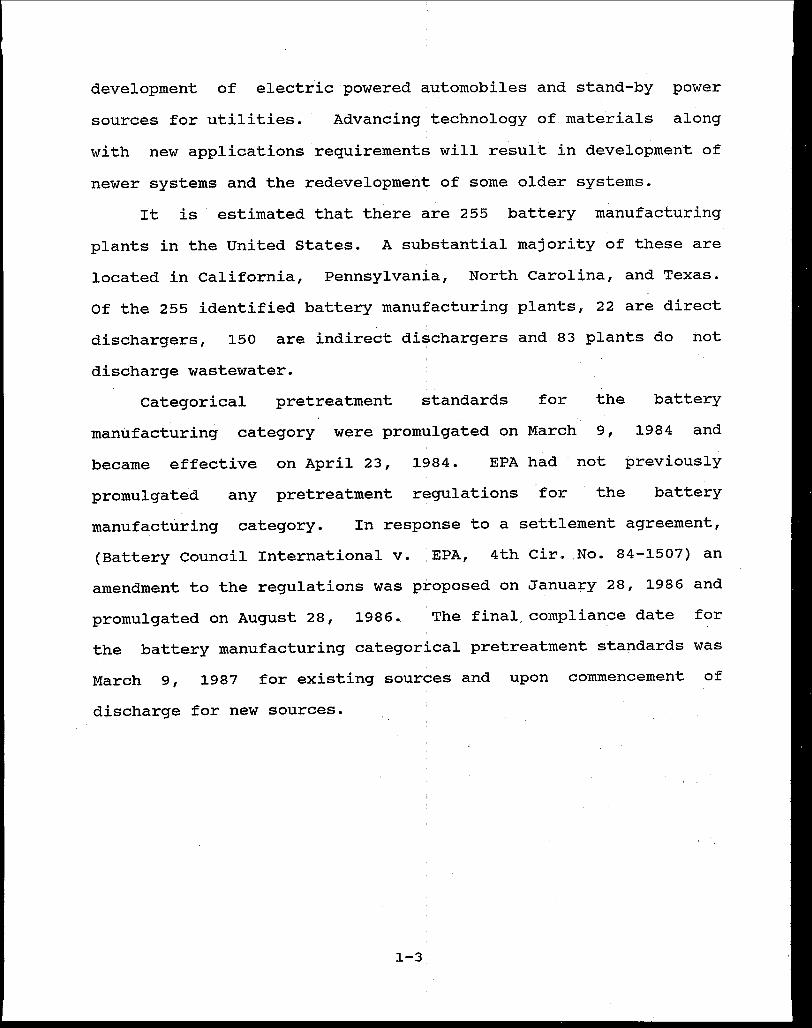
development of electric powered automobiles and stand-by power
sources for utilities. Advancing technology of materials along
with new applications requirements will result in development of
newer systems and the redevelopment of some older systems.
It is estimated that there are 255 battery manufacturing
plants in the United States. A substantial majority of these are
located in California, Pennsylvania, North Carolina, and Texas.
Of the 255 identified battery manufacturing plants, 22 are direct
dischargers, 150 are indirect di~chargers and 83 plants do not
discharge wastewater.
the categorical pretreatment standards for
manufacturing category were promulgated on March 9,
battery
1984 and
became effective on April 23, 1984. EPA had
promulgated any pretreatment regulations for
not previously
the battery
manufacturing category. In response to a settlement agreement,
(Battery council International v. :EPA, 4th Cir. No. 84-1507) an
amendment to the regulations was proposed on January 28, 1986 and
promulgated on August 28, 1986. The final, compliance date for
the battery manufacturing categorical pretreatment standards was
March 9, 1987 for existing sources and upon commencement of
discharge for new sources.
1-3

2. BATTERY MANUFACTURING CATEGORICAL PRETREATMENT STANDARDS
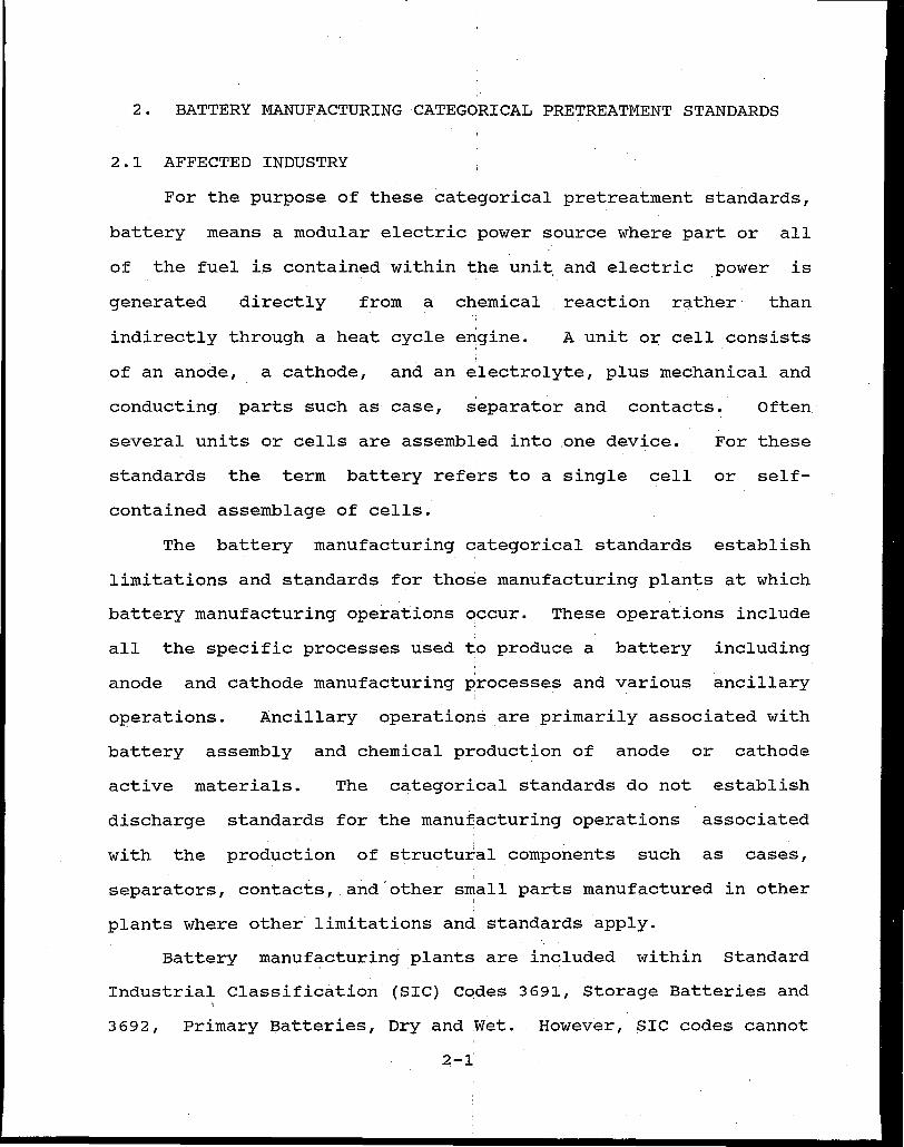
2.1 AFFECTED INDUSTRY
For the purpose of these categorical pretreatment standards,
battery means a modular electric power source where part or all
of the fuel is contained within the unit and electric power is
generated directly from a chemical reaction rather than
indirectly through a heat cycle engine. A unit or cell consists
of an anode, a cathode, and an electrolyte, plus mechanical and
conducting parts such as case, separator and contacts. Often
several units or cells are assembled into one device. For these
standards the term battery refers to a single cell or self-
contained assemblage of cells.
The battery manufacturing categorical standards establish
limitations and standards for those manufacturing plants at which
battery manufacturing operations occur.. These operations include
all the specific processes used to produce a battery including
anode and cathode manufacturing processes and various ancillary
operations. Ancillary operations are primarily associated with
battery assembly and chemical production of anode or cathode
active materials. The categorical standards do not establish
discharge standards for the manufacturing operations associated
with the production of structural components such as cases,
separators, contacts, and.other small parts manufactured in other I
plants where other limitations and standards apply.
Battery manufacturing plants are included within Standard
Industrial Classification (SIC) C~des 3691 1 Storage Batteries and
3692, Primary Batteries, Dry and Wet. However, SIC codes cannot
2-i
be used to make categorization determinations because the codes
are based on end use of the product and not the manufacturing
processes.
2.2 PROCESS OPERATIONS
Manufacturing operations vary widely, depending on the
particular battery application and the type of battery produced.
Battery manufacturing is typically comprised of production of
anodes, production of cathodes, and associated ancillary
operations necessary to produce a battery such as battery
assembly. These process operations are briefly discussed below:
Anodes - Anodes, in their final or fully charged form in a battery are usually zerovalent metals. The active mass for anodes is prepared by directly cutting and drawing or stamping the pure metal or alloyed metal sheet, by mixing metal powders with or without electrolyte, by physically applying pastes of a compound of the anode metal to the support structure, or by precipitating a soluble salt of the metal onto a carrier or support structure. The final step in anode preparation for many types of batteries, especially rechargeable ones, is formation or charging of the active mass. Formation may be carried out on individual electrodes or on pairs of electrodes (anode and cathode) in a tank of suitable electrolyte. Most often the electrodes for a battery are formed in pairs and current is passed through the electrodes to charge them. For some battery types, charge-discharge cycling up to seven times is used for formation.
cathode Manufacturing - Although usually designated by metal type cathode active materials often consist of oxidized metals, such as lead peroxide or nickel hydroxide. Non-metals such as iodine (used in lithium-iodine batteries) and meta-dinitrobenzene (used in magnesium-ammonia reserve batteries) are other kinds of cathode active materials. Cathode active materials are weak electrical conductors and usually possess little mechanical strength. Therefore, most cathodes have a metallic current conduction support structure and conducting material, often carbon or nickel, incorporated into the active mass. The active material may be applied to the support as a paste, deposited in a porous structure by precipitation from a solution,
2-2
fixed to the support as a compacted pellet, or may be dissolved in an electrolyte which has been immobilized in a porous inert structure.· Formation processes for cathodes are similar to those used for anodes.
Ancillary Operations - Ancillary operations are those operations unique to the ,battery manufacturing category that are not specifically included under anode or cathode fabrication. Ancillary operations are primarily associated with cell and battery assembly and chemical production of anode and cathode active materials. Ancillary operations also include battery washing (both intermediate and final product), and washing of equipment, floors, and operating personnel as well as so~e dry operations.
The reactive materials in most modern batteries include one
or more of the following toxic metals: cadmium, lead, mercury,
nickel, and zinc. These toxic metals are often found in
wastewater discharges and solid:wastes from battery plants.
Water is used throughout the manufacturing process, specifically
in preparation of electrolytes and electrode active masses, in.
deposition of active materials on electrode supporting
structures, in charging electrodes and removing impurities, and
in washing finished batteries, production equipment, and
manufacturing areas.
2.3 SUBCATEGORIZATION
The battery manufacturing category was subcategorized based
on anode material and electrolyte composition. The rationale for
this subcategorization is that many battery manufacturers produce
batteries with different anode-cathode pairs but with a common
anode material. The seven subcategories to which this regulation
applies are:
- Cadmium - Calcium - Lead
2-3
- Leclanche (zinc anode with an acid electrolyte) - Lithium - Magnesium - Zinc (with alkaline electrolyte)
These subcategories are represented by Subparts A-G of the
categorical standards.
These subcategories are further subdivided into
manufacturing process elements frequently ref erred to as
"building blocks" specific to basic manufacturing operations
within the subcategory. Promulgated standards are specific to
these elements. At the element level water use and pollutant
characteristics can be related to a specific measure of produc-
tion. This factor is referred to as a production normalizing
parameter (PNP). The PNP may be different in the different
subcategories or even different for each element. For example,
in the case of plants subject to the lead subcategory standards,
the PNP for all process elements for which discharge allowances
are provided (except for the truck wash process element) is the
total lead weight used (consumed) in the type of battery manufac
tured. The PNP for truck wash is the weight of lead in batteries
(not total weight of batteries) moved in trucks. This does not
apply to truck washing at plants that have battery cracking or
secondary lead smelting which is covered under nonferrous metals
manufacturing.
The seven subcategories, their manufacturing operations and
resulting wastewater characteristics are described briefly in
this section. The application of the battery manufacturing cate
gorical standards may be difficult for those unfamiliar with the
processes and terminology used. As a general guide, the Control
2-4
Authority should ask the manufacturer the questions· listed in
Table 2.1 to determine the applicable subcategories and stan-
dards. If further technical assistance is needed the Control
Authority is encouraged to contact the EPA Industrial Technology
Division project officer (Mary L. B'elefski at (202) 382-7153).
2.3.1 Cadmium Subcategory
The Cadmium Subcategory encompasses the manufacture of all '
batteries in which cadmium is the reactive anode material. Cad-
mium cells currently manufactured :are based on nickel-cadmium,
silver-cadmium, and mercury-cadmium couples. Three general met-
hods for producing anodes are employed:
1) The manufacture of pasted and pressed powder anodes by physical application of the solids;
2) Electrodeposited anodes produced by means of electrochemical precipitation of cadmium hydroxide from a cadmium salt solution;
3) Impregnated anodes manufactured by impregnation of cadmium solutions into porous structures and subsequent precipitation of cadmium hydroxide.
Five cathode manufacturing process elements are employed in
this subcategory, three of which are specifically for production
of nickel cathodes and two are for production of silver and
mercury cathodes. They include:
(1)
(2)
(3)
(4)
(5)
Nickel pressed powder cathodes
Nickel electrodeposited cathodes
Nickel impregnated cathodes
Silver powder pressed cathodes
·Mercuric oxide powder pressed
2-5' !
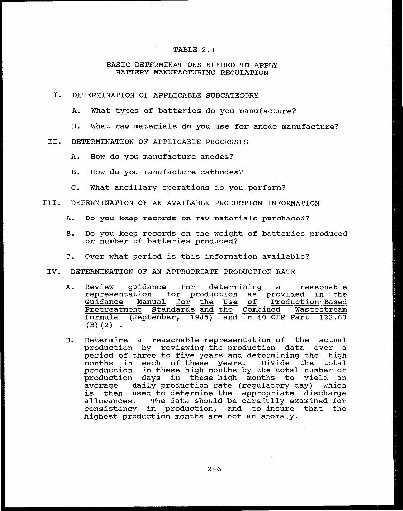
TABLE 2.1
BASIC DETERMINATIONS NEEDED TO APPLY BATTERY MANUFACTURING REGULATION
I. DETERMINATION OF APPLICABLE SUBCATEGORY
A. What types of batteries do you manufacture?
B. What raw materials do you use for anode manufacture?
II. DETERMINATION OF APPLICABLE PROCESSES
A. How do you manufacture anodes?
B. How do you manufacture cathodes?
C. What ancillary operations do you perform?
III. DETERMINATION OF AN AVAILABLE PRODUCTION INFORMATION
A. Do you keep records on raw materials purchased?
B. Do you keep records on the weight of batteries produced or number of batteries produced?
c. Over what period is this information available?
IV. DETERMINATION OF AN APPROPRIATE PRODUCTION RATE
A. Review guidance for determining a reasonable representation for production as provided in the Guidance Manual for the Use of Production-Based Pretreatment Standards and the Combined Wastestream Formula (September, 1985) and in 40 CFR Part 122.63 (B) (2) •
B. Determine a reasonable representation of the actual production by reviewing the production data over a period of three to five years and determining the high months in each of these years. Divide the total production in these high months by the total number of production days in these high months to yield an average daily production rate (regulatory day) which is then used to determine the appropriate discharge allowances. The data should be carefully examined for consistency in production, and to insure that the highest production months are not an anomaly.
2-6
Assembly of all cells in this subcategory involves the
assembly of one or more anodes with cathodes and separators to
produce an active cell. One or more of these cells is then
inserted in a battery case, electrical connections are made, and
electrolyte is added, after which the case is covered and (if
appropriate) sealed.
Ancillary operations include washing assembled cells;
preparing electrolyte solutions; cleaning process areas and
equipment; employee washing to remove process chemicals; and the
production of active anode and cathode materials such as cadmium
powder, silver powder, nickel hy~roxide and cadmium hydroxide.
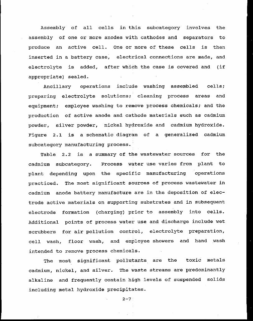
Figure 2.1 is a schematic diagram of a generalized cadmium
subcategory manufacturing process.
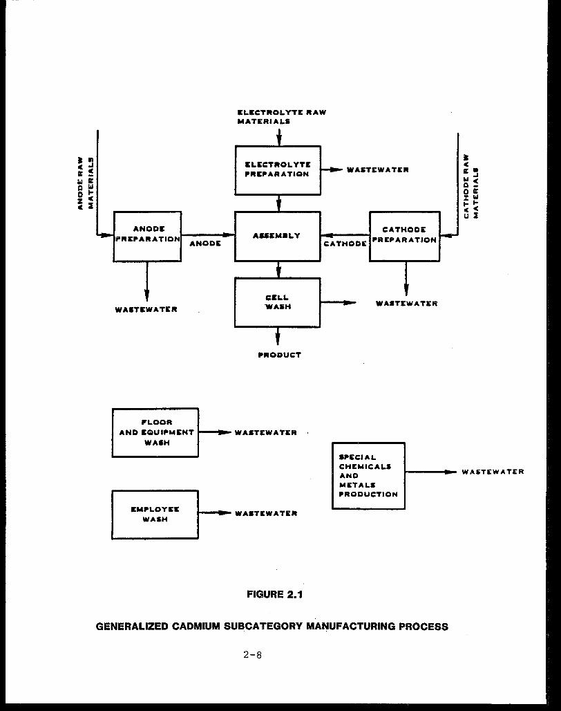
Table 2.2 is a summary of the wastewater sources for the
cadmium subcategory. Process water use varies from plant to
plant depending upon the specific manufacturing operations
practiced. The most significant sources of process wastewater in
cadmium anode battery manufacture are in the deposition of elec-
trode active materials on supporting substrates and in subsequent
electrode formation (charging) prior to assembly into cells.
Additional points of process water use and discharge include wet
scrubbers for air pollution control, electrolyte preparation, I
cell wash, floor wash, and employee showers and hand wash
intended to remove process chemicals.
The most significant pollutants are the toxic metals
cadmium, nickel, and silver. The waste streams are predominantly
alkaline and frequently contain high levels of suspended solids
including metal hydroxide precipitates.
. ~ c c llC -w llC Q ~ 0 c ~ :I
IELIECTROLYTE RAW MATERIAL5
ANODE
PREPARATION ANODE
WASTEWATER
P'LOOR
!ELECTROLYTE PREPARATION
AUEMaLY
CELL WASH
PRODUCT
AND EQUIPMENT t---!~ WASTEWATER
WASH
WASTEWATER
CATHODE
CATHODE PREPARATION
WA•TEWATER
SPECIAL
• c llC. w _, 0 ~ 0 llC % w .... cc u J
CHEMICALS t--~~--- WASTEWATER AND
EMPLOYEE
WASH t---1 ... WASTEWATER
FIGURE 2.1
METALS PRODUCTION
GENERALIZED CADMIUM SUBCATEGORY MA~UFACTURING PROCESS
2-8
Grouping
Anode Manufacture
Cathode Manufacture
Ancillary Operations
TABLE 2.2
CADMIUM SUBCATEGORY ANALYSIS
Element
Pasted and Pressed' Powder
Electrodeposited
Impregnated
Silver Powder Pressed
Specific Wastewater Sources (Subelement)
• Process Area Clean-up
• Product Rinses • Spent Caustic • Scrubbers
• Sintered Stock Preparation Clean-up
e Impregnated Rinses • .Spent Impregnation Caustic o Product Cleaning • Pre-formation Soak • Spent Formation Caustic • Post-formation Rinse
• No Process Wastewater
Nickel Pressed Powder • No Process Wastewater
Nickel Electrodeposited • Spent Caustic • Post-formation Rinse
Nickel Impregnated • Sintered Stock Preparation
Mercuric Oxide Powder
Clean-up • Impregn,ation Rinses • Impregnation Scrubbers • Product Cleaning • Impregnated Plague Scrub • Pre-formation Soak • Spent Formation Caustic • Post Formation Rinses • Impregnation Equipment Wash e NicJ{.el Recovery Filter Wash • Nickel Recovery Scrubber
Pressed • No Process Wastewater
Cell Wash • Cell Wash
2-9.
Grouping
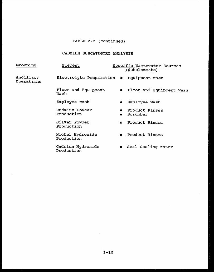
Ancillary Operations
TABLE 2.2 (continued)
CADMIUM SUBCATEGORY ANALYSIS
Element Specific Wastewater Sources (Subelements)
Electrolyte Preparation • Equipment Wash
Floor and Equipment Wash
Employee Wash
Cadmium Powder Production
Silver Powder Production
Nickel Hydroxide Production
Cadmium Hydroxide Production
2-10
• Floor and Equipment
• Employee Wash
• Product Rinses • Scrubber
• Product Rinses
• . Product Rinses
• Seal Cooling Water
Wash
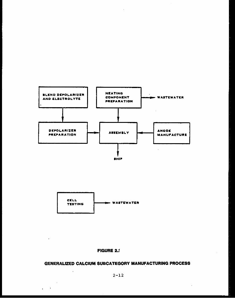
2.3.2 Calcium Subcategory
The Calcium Subcategory includes batteries that use calcium
as the reactive anode material.. currently, only thermal
batteries for military applications are produced. These batteries
are designed for long-term inactive storage followed by rapid
activation and delivery of relatively high curr~nts for short
periods of time. These characteristics are achieved by the use
of solid electrolytes (usually :a fused mixture of lithium
chloride-potassium chloride) which at the moment of use are
heated to above the melting point .to activate the cell. This
heat is supplied by chemical :reactants incorporated as a
pyrotechnic device in the cell. Cell anodes, depolarizers,
electrolytes, and. cell activators (peating elements) are prepared
in the manufacture of calcium anode thermal · batteries. Calcium
anode material is generally prodµced by vapor deposition of
calcium on a substrate of metal, such as nickel or iron, which
serves as a current collector and support for the calcium during
cell operation. Cathodic depolarizers include calcium chromate,
tungstic oxide, and potassium dichromate and are incorporated
into cells by impregnation of fibrous media, pelletization of
powders, and by glazing. The electrolyte usually consists of a
lithium chloride-potassium chloride mixture and is incorporated
into the cells in a similar manner as are the depolarizers.
Figure 2.2 shows a generalized diagram for calcium battery
manufacturing.
Table 2.3 shows a summary of the wastewater sources for each
process in the subcategory. Since calcium, the cell anode
material, reacts vigorously with water, water use is avoided as
2-11:
. 8LICNC DEPOLARIZER AND ELCCTROL YTE
'"
DIEPOLAIUZICR PREPARATION
C:l:LL TESTINc:;
HEATING COMPONENT - WASTEWATER PRl:PARA TION
ASSICM8LY ANODIC MAHUP'ACTUfU:
8HIP
...._ __ ..,.. WASTICWATICR
FIGURE 2.:
GENERALIZED CALCIUM SUBCATEGORY MANUFACTURING PROCESS
2-12

Grouping
Anode Manufacture
cathode Manufacture
Ancillary
TABLE'2.3
CALCIUM SUBCATEGORY ANALYSIS
Element
Vapor Deposited Fabricated ·
Calcium Chromate
Tungstic oxide
Potassium Dichromate
Heating Component Production:
Heat Paper
Heat Pellet
Cell Testing
2-13
Specific Wastewater Sources (Subelements)
• No Process Wastewater
• No Process Wastewater
• No Process Wastewater
• No Process Wastewater
• No Process Wastewater
• Slurry Preparation • Filtrate Discharge
• No Process Wastewater
e Leak Testing

much as possible. The most significant pollutants found in these
wastewaters are chromium (especially hexavalent chromium from
barium chromate) and asbestos. Both of these pollutants are
from raw materials used in the manufacture of heating components.
2.3.3 Lead Subcategory
The Lead Subcategory, which is the subcategory with the
largest number of plants and volume of production, includes
batteries which use lead anodes, lead peroxide cathodes, and acid
electrolytes. The subcategory includes lead acid reserve cells
and the more familiar lead acid storage batteries. Lead acid
batteries include cells with immobilized electrolytes for use in
portable devices; batteries used for automotive starting,
lighting, and ignition (SLI) applications; and a variety of
batteries designed for industrial applications. Lead reserve
batteries are similar to dehydrated plate lead batteries and are
produced from lead electroformed on steel which is immersed in an
acid electrolyte when placed in use.
SLI and industrial type batteries are manufactured and
shipped as "dry-charged" (shipped without acid electrolyte) and
"wet-charged" (shipped with acid electrolyte) units. Batteries
shipped without electrolyte include damp-charged batteries (damp
batteries) and dehydrated plate batteries (dehydrated batteries).
Damp batteries are usually manufactured by charging the elec
trodes in the battery case after assembly (closed formation), and
emptying the electrolyte before final assembly and shipping.
Dehydrated batteries usually are manufactured by charging of the
electrodes in open tanks (open formation) followed by rinsing and
'2-14
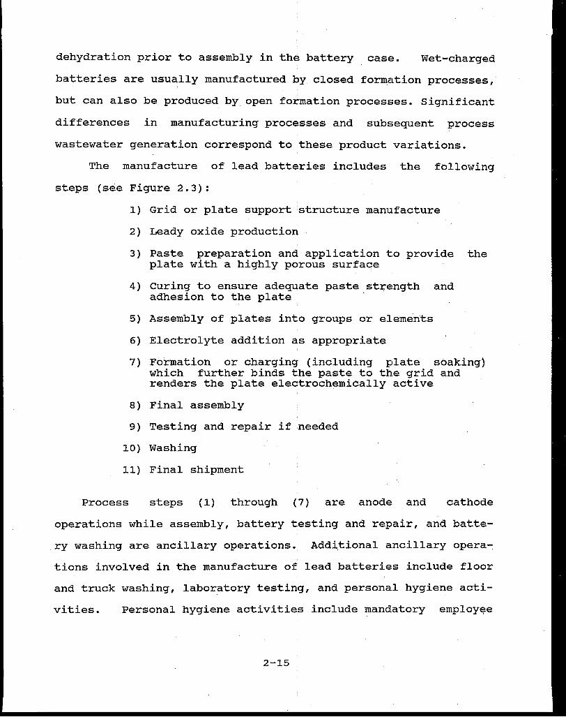
dehydration prior to assembly in the battery case. Wet-charged
batteries are usually manufactured by closed formation processes,
but can also be produced by open formation processes. Significant
differences in manufacturing processes and subsequent process
wastewater generation correspond to these product variations.
The manufacture of lead batteries includes the following
steps (see Figure 2.3):
1) Grid or plate support :structure manufacture
2) Leady oxide production
3) Paste preparation and application to provide the plate with a highly porous surface
4) Curing to ensure adequate paste.strength and adhesion to the plate
5) Assembly of plates into groups or elements
6) Electrolyte addition as appropriate
7) Formation or charging (including plate soaking) which further binds the paste to the grid and renders the plate electrochemically active
8) Final assembly
9) Testing and repair if :needed
10) Washing
11) Final shipment
Process steps (1) through (7) are anode and cathode
operations while assembly, battery testing and repair, and batte
ry washing are ancillary operations. Addi.tional ancillary opera-:
tions involved in the manufacture of lead batteries include floor
and truck washing, laboratory testing, and personal hygiene acti-
vi ties. Personal hygiene activitie.s include mandatory employee
2-15

LEAD
LE ADV OXIDE PRODUCTION
PbO·Pb __ ..--....l"--~L...I
SULFUfUC ACID ----~-----"'
PASTE PbO·Pb RECYCLED TO MIXER
,.. SEPARATORS
OPEN FORMATION DEHYDRATED LINE
FORM
DRAIN
RINSE
ORV
ASSEMBLY
IURN POST
SEAL
WASTEWATER WATER
... ECYCLED TO SMELTER
SCRUBBER PIG LEAD OR SHEET LEAD
' WASTE GRID WATER MANUFACTURE
SCRUBBER
WASTEWATER
LEAD DROSS• PLUS REJECTS PASTING
MACHINE WITH DAYER 1-----------... RECYCLED OR
PbO CLEAN·UP TO TREATMENT
STORAGE ORCUAE OF PLATES
DRY BAG HOUSE
------REJECT• ousr· STACKER PLATES
WELD ASSEMBLED ELEMENTS
BATTERY CASE & COVER
REJECT• PLATES
FRESH ACID
CLOSED FORMATION WET BATTERY LINE
ASSEMBLY
BURN POS1
ACID FILL
FORM
DUMP
FILL
BOOST CHARGE
WASH ._----~WASTEWATER
TEST REJECTS•
PRODUCT
FIGURE 2.3
SMALL PARTS CASTING !FOR ASSEMBLY)
ANCILLARY OPERATIOl'l.S
~ WASTEWATER
PERSONAL HYGIENE
+ WASTEWATER
LEAD SUBCATEGORY GENERALIZED MANUFACTURING PROCESS
2-16
WASTE WAT!
handwashing, respirator washing, and launqering of employee
work uniforms.
In general, process wastewater discharges result from the
preparation and application of eleqtrode active materials (steps
1-6 above), formation and charging '(step 7), washing finished
batteries (step 10 above), and from the various ancillary op
erations (floor and truck washing, laboratory testing, and per
sonal hygiene activities). Table 2.4 is a summary of wastewater
sources for each process in the lead subcategory. Wastewater
from the manufacture of lead batteries is acidic as a result of
contamination with sulfuric acid electrolyte and
contains dissolved lead and suspended particulates
lead solids).
2.3.4 Leclanche Subcategory
generally
(including
The Leclanche Subcategory includes the manufacture of
batteries that consist of a zinc anode, a carbon-manganese di
oxide cathode, and an acid electrolyte (zinc chloride or zinc
chloride-ammonium chloride). Batteries in this subcategory con
tain mercury which is used to amalgamate the zinc and reduce
internal corrosion. The mercury is generally added to the cell
electrolyte or separator. Types of batteries include the
familiar conventional carbon-zinc Leclanche cells or "dry cells"
(cylindrical, rectangular and flat), silver chloride-zinc cells
(less than 0.01 percent of total prpduction in the subcategory),
carbon-zinc air cells, and foliar · batteries. Carbon-zinc air
depolarized batteries which use alkaline electrolytes are
included in the Zinc Subcategory.
2-17
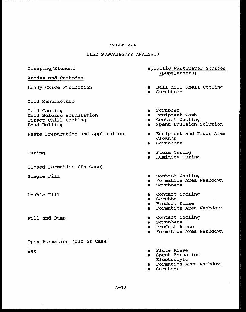
TABLE 2.4
LEAD SUBCATEGORY ANALYSIS
Grouping/Element
Anodes and cathodes
Leady oxide Production
Grid Manufacture
Grid Casting Mold Release Formulation Direct Chill Casting Lead Rolling
Paste Preparation and Application
curing
Closed Formation (In Case)
Single Fill
Double Fill
Fill and Dump
Open Formation (Out of case)
Wet
2-18
Specific Wastewater Sources ( Subelements)
• Ball Mill Shell Cooling • Scrubber*
• Scrubber • Equipment Wash • Contact Cooling • Spent Emulsion Solution
• Equipment and Floor Area Cleanup
• Scrubber*
• Steam Curing • Humidity curing
• Contact Cooling • Formation Area Washdown • Scrubber*
• Contact Cooling • Scrubber • Product Rinse • Formation Area Washdown
• Contact Cooling • Scrubber* • Product Rinse • Formation Area Washdown
• Plate Rinse • Spent Formation
Electrolyte • Formation Area Washdown • Scrubber*
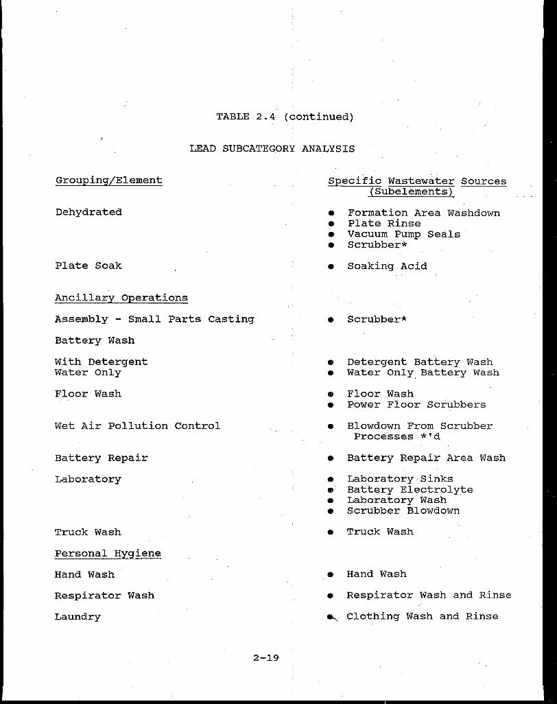
TABLE 2.4 (continued)
LEAD SUBCATEGORY ANALYSIS
Grouping/Element
Dehydrated
Plate Soak
Ancillary Operations
Assembly - Small Parts casting
Battery Wash
With Detergent Water Only
Floor Wash
Wet Air Pollution Control
Battery Repair
Laboratory
Truck Wash
Personal Hygiene
Hand wash
Respirator Wash
Laundry
2-19
Specific Wastewater Sources ( Subelements)
e Formation Area Washdown e Plate Rinse e Vacuum Pump Seals · e Scrubber*
e Soaking Acid
e Scrubber*
• Detergent Battery Wash e Water Only. Battery Wash
• Floor Wash e Power Floor Scrubbers
• Blowdown From Scrubber Processes *'d
• Battery Repair Area Wash
e Laboratory Sinks • Battery Electrolyte e Laboratory wash • Scrubber Blowdown
• Truck Wash
• Hand Wash
e Respirator Wash and Rinse
e..__ Clothing Wash and Rinse
The manufacture of batteries in this subcategory is com
prised of the anode preparation, cathode preparation,the prepara
tion or application of a separator, assembly of components into
cells and batteries, and ancillary operations performed in sup
port of these basic manufacturing steps. Figure 2.4 is a
schematic diagram of a generalized Leclanche Subcategory
manufacturing process. Discharges from the manufacture of zinc
cans formed from zinc sheet are not regulated under the battery
manufacturing category. The flow allowance for all processes
except foliar miscellaneous equipment wash is 0.0 l/kg cells
produced.
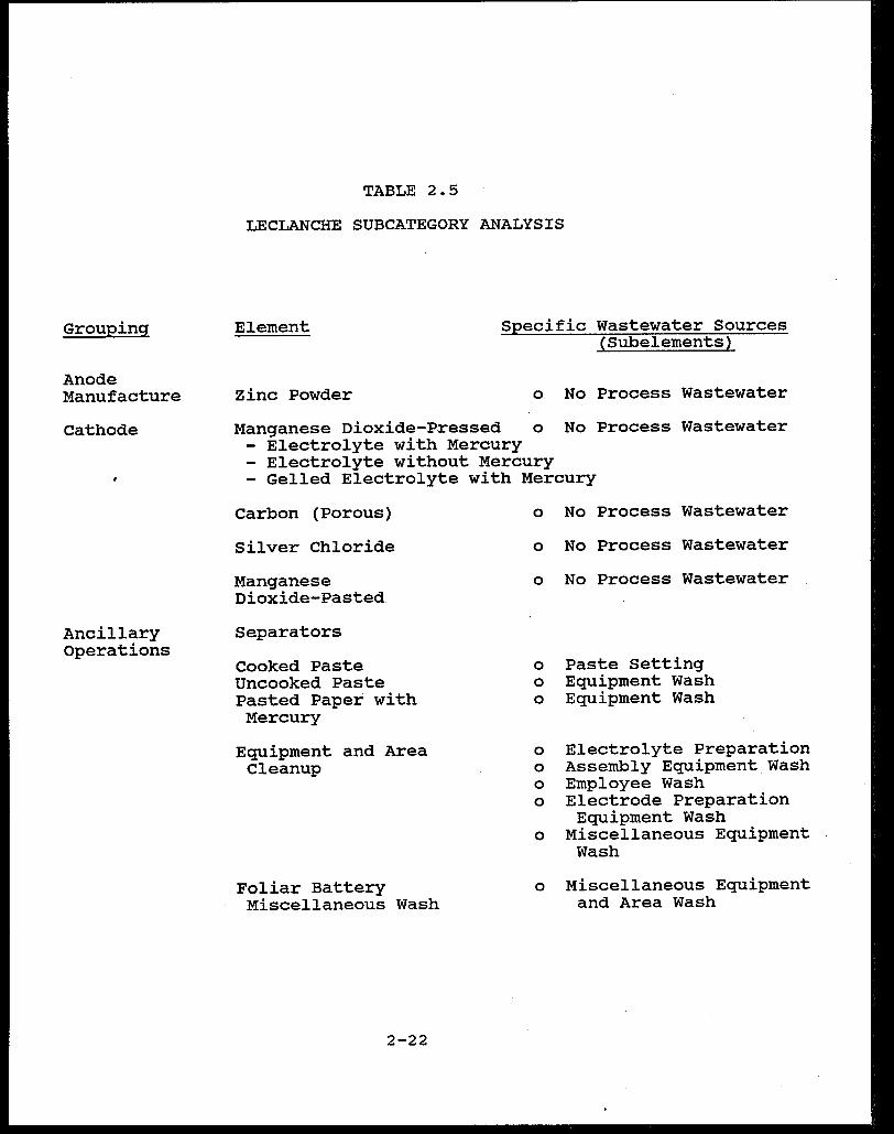
Table 2.5 is a summary of the wastewater sources for this
subcategory. Wastewater discharges in this subcategory are
generally low and result only from separator production and from
cleanup of miscellaneous equipment. Themost'significant pollu
tants in the wastestreams are mercury, zinc, ammonium chloride,
manganese dioxide and carbon. Starch and flour may also be
present from separator production. Recycle and reuse is
performed where possible in this subcategory to eliminate the
discharge of pollutants.
2.3.5 Lithium Subcategory
The Lithium Subcategory encompasses the manufacture of bat
teries that use lithium as the reactive anode material. Included
are batteries for heart pacemakers, lanterns, watches, and
special military applications (such as thermal batteries). A
variety of cell cathode depolarizer materials are currently used
with lithium anodes including iodine, sulfur dioxide, thionyl
2-20

ZINC
l:Ll:CTROLYTI: RAW
MATERIALS
ELECTROLYTE P'ORMULATION.
...---1--, I ANODE 'ANODE I METAL ASSEMBLY
.._~~~=-_J
MISCELLANEOUS TOOLS AND EQUIPMENT P'ROM ALL OPERATIONS
PRODUCT
SEPARATOR RAW
MATERIALS
SEPARATOR PREPARATION ....... _ WASTEWATER
CATHODE RAW MATERIALS
CATHODE PREPARATION
EQUIPMENT
AND AREA CLEANUP
1-.... WASTEWATER
- - - OPERATION NOT REGULATED IN BATTERY MANUP'ACTURING POINT SOURCE CATEGORY
FIGURE 2.4
.GENERALIZED SCHEMATIC FOR LECi.ANCHE CELL MANUFACTURE
2-21
Grouping
Anode Manufacture
cathode
Ancillary Operations
TABLE 2.5
LECLANCHE SUBCATEGORY ANALYSIS
Element
Zinc Powder
Specific Wastewater sources (Subelements)
o No Process Wastewater
Manganese Dioxide-Pressed o No Process Wastewater - Electrolyte with Mercury - Electrolyte without Mercury - Gelled Electrolyte with Mercury
Carbon (Porous)
Silver Chloride
Manganese Dioxide-Pasted
Separators
Cooked Paste Uncooked Paste Pasted Paper with Mercury
Equipment and Area Cleanup
Foliar Battery Miscellaneous Wash
2-22
o No Process Wastewater
o No Process Wastewater
o No Process Wastewater
o Paste Setting o Equipment wash o Equipment Wash
o Electrolyte Preparation o Assembly Equipment Wash o Employee Wash o Electrode Preparation
Equipment Wash o Miscellaneous Equipment
Wash
o Miscellaneous Equipment and Area Wash

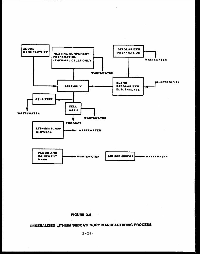
chloride, and iron disulfide. Because lithium reacts vigorously
with water, electrolytes used in ~hese batteries are generally
organic liquids, solids, or, in the case of thermal batteries,
solid inorganic salts which are fused during activation. The
manufacture of lithium anodes (Figure 2.5) generally involves
mechanical forming of metallic lithium to the desired configura-
tion. Cell cathode depolarizers are frequently blended with or
dissolved in the cell electrolyte. Thermal batteries manufac-
tured in this subcategory include a heating component (activator)
in addition to the anode; cathode depolarizer and electrolyte.
Due to lithium's high reactivity with water, anode proces-
sing and most cell assembly operations are performed without the
use of process water. Most assembly is accomplished in areas of
controlled low humidity. Process w~ter is used in producing some
cell cathodes (specifically, lead iodide, iron disulfide, sulfur
dioxide, and thionyl chloride cathode production), either for
washing reactive materials or for air pollution control and area
cleanup.
The wastewaters from cathode operations, cell testing,
lithium scrap disposal, air scrubbers, and floor and equipment
wash contain metals and other pollutants. Pollutants found in
lithium subcategory wastewaters include asbestos, chromium, lead, I
zinc, cobalt, iron, COD and TSS. Table 2.6 is a summary of the
wastewater sources for the Lithium Subcategory.
2.3.6 Magnesium Subcategory
' The Magnesium Subcategory includes manufacturing operations
.used to produce cells which pair magnesium anodes with various
2-23
WA
ANODE MANUP'ACTURE
HEATING COMPONENT PREP'ARATION -(THI:: RM AL CELLS ONLY)
WASTEWATER
- AUEM8LY
-
- Cl'LL TEST -CELL WAaH
~ STEWATEll
I WASTEWATER
PllODUCT
LITHIUM SCRAP' ~--· DISP'OIAL W ASTEW A TIER
DEPOLARIZER PREPARATION t
WAITE WATER
8LEND I DEPOLARIZER
ELECTROLYTE
IELECTROLYTE
P'LOOR AND EQUIP'MENT WASH
.,__ ..... WASTEWATER I AIR •CRU••ERS ~WASTEWATER
FIGURE 2.5
GENERALIZED LITHIUM SUBCATEGORY MANUFACTURING PROCESS
2-24·

Grouping
Anode Manufacture
cathode Manufacture
Ancillary Operations
TABLE 2.6
LITHIUM SUBCATEGORY ANALYSIS
Element
Formed and Stamped
Iodine Iron Disulfide Lead Iodide Lithium Perchlorate Sulfur Dioxide* Thionyl Chloride* Titanium Disulfide
Specific Wastewater Sources ( Subelements)
• No Process Wastewater
• No Process Wastewater • Product Treatment • Equipment Wash • No Process Wastewater e Spills • Spills • No Process Wastewater
Heating Component Production:
Heat Paper
Heat Pellets Lithium Scrap Disposal Cell Testing Floor and Equipment
Wash Air Scrubbers Cell Wash
• Filtrate Discharge • Slurry Preparation • No Process Wastewater • Scrap Disposal • Leak Testing e Floor and Equipment Wash • Blowdown from various
production areas • Cell Wash
* - Wastewater discharged from air scrubbers for the manufacture of these cathodes is included with ancillary operations.
2-25

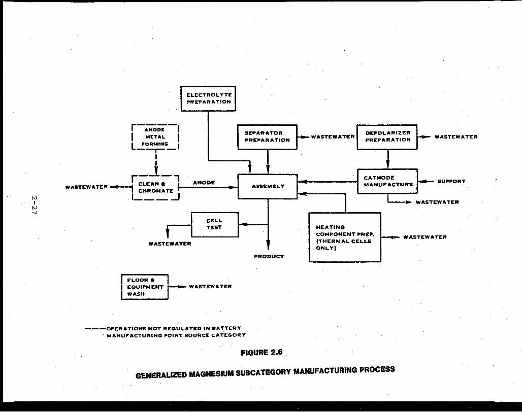
cathode materials such as manganese diox~de, barium
lithium chromate, magnesium hydroxide, and carbon.
chromate,
Carbon is
used in magnesium-carbon batteries which constitute 85% of total
subcategory production. Other cathode materials include: vanadium
pentoxide for thermal batteries; copper chloride, lead chloride,
silver, or silver chloride for magnesium reserve batteries; and
m-dinitrobenzene for ammonia activated cells. Electrolyte
materials consist of magnesium perchlorate, magnesium bromide,
lithium chloride, potassium chloride, and ammonia. Anode
manufacture generally requires mechanical forming and cutting of
magnesium metal, and cleaning and chromating to protect against
corrosion. Discharges from these mechanical and chromating opera
tions are not regulated under the battery manufacturing
categorical standards. Cathodes are prepared by several
techniques including blending and pressing of powdered materials
and chemical treatment operations. Heating components
(activators) are manufactured for thermal batteries. Figure 2.6
is a schematic diagram of the magnesium battery manufacturing
process.
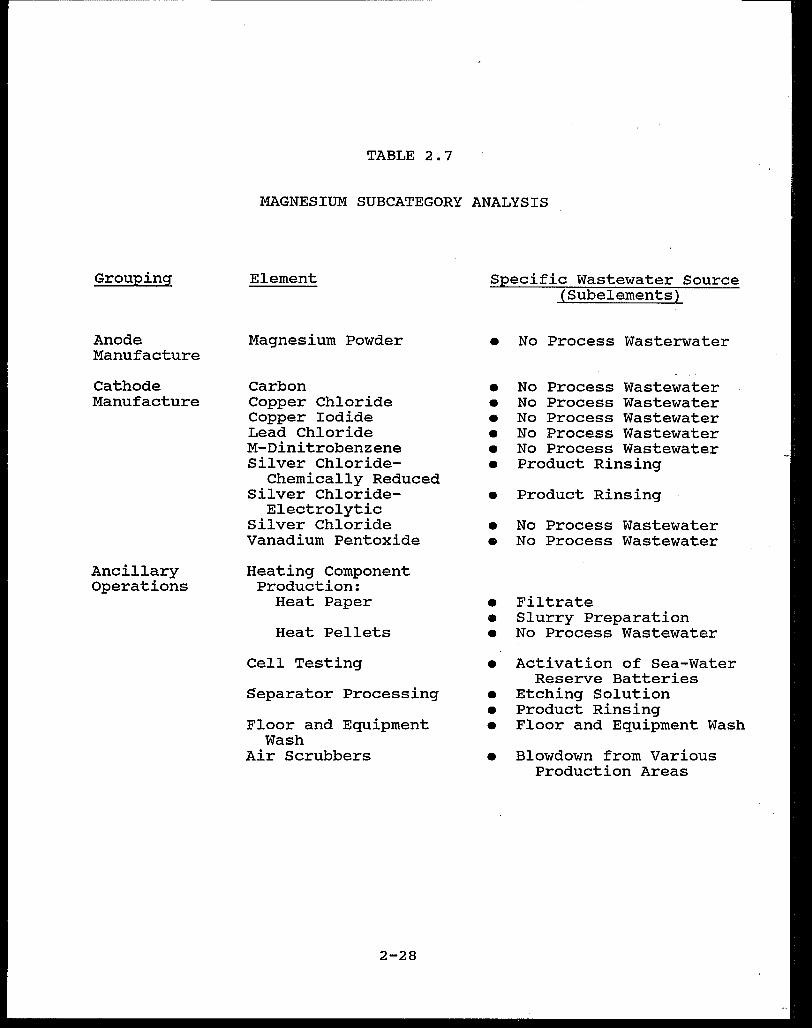
Pollutants resulting from magnesium anode battery manufac
ture include asbestos, chromium (primarily hexavalent) from heat
paper production, silver, lead, nickel, iron, COD and TSS. Table
2.7 is a summary of the wastewater sources for the subcategory.
2.3.7 Zinc Subcategory
The Zinc Subcategory includes batteries that have an amalga
mated zinc anode and an aqueous alkaline electrolyte (usually
potassium or sodium hydroxide). The zinc is amalgamated to
2-26
N I
N -i
r-~~-1 I METAL I L..!~~G-'
I
ELECTROLYTE PREPARATION
r-1-, WASTEWATER ........... CLEAN • I ANODE
I CHROMA TE .. I , ___ _J
t CELL TEST
WASTEWATER
FLOOR• EQUIPMENT
WASH
WASTEWATER
SEPARATOR
PREPARATION
l ASSEMBLY
I
,.ROl;>UCT
---OP"ERATIONS NOT REGULATED IN BATTERY MANUFACTURING P"OINT SOURCE CATEGORY
FIGURE 2.6
!-4--WASTEWATER DEP'OLARIZER PREPARATION ~ WASTEWATER
CATHODE MANUFACTURE~ SUP'PORT
HEATING
COMPONENT P'REP'. !THERMAL CELLS ONLYI
WASTEWATER
1--119- WASTEWATER
GENERALIZED MAGNESIUM SUBCATEGORY MANUFACTURING PROCESS
Grouping
Anode Manufacture
cathode Manufacture
Ancillary Operations
TABLE 2.7
MAGNESIUM SUBCATEGORY ANALYSIS
Element
Magnesium Powder
carbon Copper Chloride Copper Iodide Lead Chloride M-Dinitrobenzene Silver Chloride-
Chemically Reduced Silver Chloride
Electrolytic Silver Chloride Vanadium Pentoxide
Heating Component Production:
Heat Paper
Heat Pellets
Cell Testing
$eparator Processing
Floor and Equipment Wash
Air Scrubbers
2-28
Specific Wastewater Source ( Subelements)
• No Process Wasterwater
• No Process Wastewater • No Process Wastewater • No Process Wastewater • No Process Wastewater • No Process Wastewater • Product Rinsing
• Product Rinsing
• No Process Wastewater • No Process Wastewater
• Filtrate • Slurry Preparation • No Process Wastewater
• Activation of Sea-Water Reserve Batteries
• Etching Solution • Product Rinsing • Floor and Equipment Wash
• Blowdown from Various Production Areas
reduce anode corrosion and self-discharge of the cell. Batteries
manufactured differ considerably in physical configuration and in
production techniques depending upon the desired operational
characteristics of the cells. six different cathode systems are
used to produce five types of batteries including alkaline
manganese batteries (manganese dioxide cathode system); carbon
zinc air batteries (porous carbon~atmospheric oxygen cathode
system); silver oxide zinc batteries (monovalent or divalent
silver oxide cathode system); mercury zinc batteries (mercuric
oxide and mercuric oxide with cadmium oxide cathode system); and
nickel zinc batteries (nickel hydroxide cathode system).
Manufacturing processes differ widely within the subcategory
resulting in differences in process water use and wastewater
discharge at each plant. There are, seven distinct anode process
operations, ten distinct cathode process operations and eight
ancillary operations in various combinations at plants in the
subcategory~· Ancillary processes are associated with cell
assembly, metal oxide production specific to battery
manufacturing, and general plant production activity from which
wastewater is generated and discharged. Figure 2.7 is a
schematic diagram of generalized zi~c subcategory manufacturing
processes.
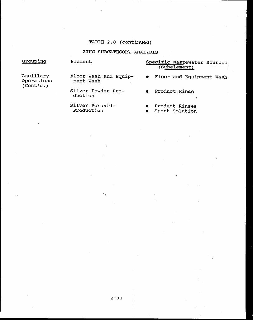
Table 2.8 is a summary of the ~astewater sources for this
subcategory. Pollutants found in zinc subcategory wastewater
streams are primarily metals including zinc, mercury, silver and
nickel; oil and grease; and TSS.
2-29

ANODE RAW MATERIAL.S
~ WASTEWATl'R
AMAl.titAMATION t---t_.
ANODE PREl'ARATION
ANODIC P'ORMATION
l:MPt..OYEE WASH
P'LOOR AND EQUIPMENT WASH
WASTEWATER
WASTEWATER
ANODIC
W ASTEWA TICR .
WA STEW A TEJll
ICl.ECTROI. YTE RAW MATERIA&.S
SPECIAL. CHEMIC.AU, METALS PRODUCTION
1:1.ECTROt.. YTE WASTEWATER PREPARATION
CATHODE ltAW MATERIAl.S
~ CHEMICAL. "fltEPARATION WASTEWATER OP' DEl'O&.ARIZE.,
CATHODE WASTEWATER ""E"ARATION t---t_.
CATHODE WASTEWATtR
P'ORMATION -
ASSEM•l.Y CATHODE
CSL.I. WASH
PRODUCT
------ I REJECTS
t REJECT C:ELL WASTEWATICR
WASTEWATER HANDLING
llLVIR ITC:H
W ASTEW A.TER
FIGURE 2~7
GENERALIZED ZINC SUBCATEGORY MANUFACTURING ~ROCESSES
2-30

Grouping
Anode Manufacture
Cathode Manufacture
TABLE 2.8
ZINC SUBCATEGORY ANALYSIS
Element
Cast or Fabricated
Zinc Powder-Wet Amalgamated
Zinc Powder-Gelled Amalgam
Zinc Powder..,.Dry Amalgamated
Zinc Oxide PowderPasted or Pressed
Zinc Oxide PowderPasted or Pressed, Reduced
Zinc Electrodeposited
Porous Carbon
Manganese DioxideCarbon
Mercuric oxide (and mercuric oxide -manganese dioxide carbon)
Mercuric OxideCadmium oxide
2-31
Specific Wastewater Sources {Subelement)
• No Process Wastewater
• Floor Area and Equipment Cleanup
• Spent Aqueous Solution • Amalgam Rinses • Reprocess Amalgam Rinses
• Floor Area and Equipment Cleanup
• No Process Wastewater
• No Process Wastewater
• Post-formation Rinse
• Post-electrodepositiori Rinses
• Spent Amalgamation Solution
• Post-amalgamation Rinse
• No Process Wastewater
• No Process Wastewater
• No Process Wastewater
• No Process Wastewater

Grouping
cathode Manufacture (Cont'd.)
Ancillary Operations
TABLE 2.8 (continued)
ZINC SUBCATEGORY ANALYSIS
Element
Silver Powder Pressed
Silver Powder Pressed and Electrolytically Oxidized (Formed)
Silver Oxide (Ag O) Powder
2
Silver Oxide (Ag O) Powder-
2 Thermally Reduced or Sintered, Electrolytically Formed
Silver Peroxide (AgO) Powder
Nickel Impregnated and Formed
Cell Wash
Electrolyte Preparation
Silver Etch
Mandatory Employee Wash
Reject Cell Handling
2-32
Specific Wastewater Sources ( Subelement)
• No Process Wastewater
• Post-formation Rinse
• No Process Wastewater
• Slurry Paste Preparation • Spent Caustic Formation • Post-formation Rinse
• Utensil Wash • Spent Solution • Product Rinse • Product Soak
Ref er to Cadmium Sub-category Analysis (Table 2.2)
• Acetic Acid Cell Wash • Chromic Acid Containi~g
• Cell Wash ~
Methylene Chloride Ce 1 Wash
• Freon Cell Wash
• Non-chemical Cell Wash
• Equipment Wash
• Product Rinse
• Employee Wash
• Reject Cell Handling
Grouping
'Ancillary Operations (Cont'd.)
TABLE 2.8 (continued)
ZINC SUBCATEGORY ANALYSIS
Element
Floor Wash and Equip~ ment Wash
Silver Powder Production
Silver Peroxide Production
2-33
Specific Wastewater Sources (Subelement)
• Floor and Equipment Wash
• Product Rinse
• Product Rinses • Spent Solution
2.4 OPERATIONS COVERED UNDER OTHER CATEGORIES
Battery manufacturers perform many process operations on
site which are not unique to battery manufacturing. Many of
these operations are addressed in categorical standards for other
industrial categories. A partial list of these operations in-
eludes:
- Plastic and Rubber Battery Case Manufacture
- Cell Containers and Components: A. Forming B. Cleaning and Deburring c. Metal Surface Treatment
(i.e., plating, chromating, etc.)
- Retorting, Smelting, and Alloying Metals
- Inorganic Chemical Production (not specific to Battery Manufacturing)
- Pasted Paper Manufacture (without mercury)
2.5 PRETREATMENT STANDARDS FOR THE BATTERY MANUFACTURING CATEGORY
The battery manufacturing categorical standards (40 CFR 461)
establish pretreatment standards for existing and new sources
(PSES and PSNS) that manufacture batteries. PSES are not promul
gated for the calcium and lithium subcategories because the
amount and toxicity of the existing discharges did not justify
the development of National Standards. If the Control Authority
encounters wastewater discharged from any processes in these
subcategories, discharge allowances should be established using
guidance contained in. Volume I of the final development document
for battery manufacturing.
Several unit processes that are associated with other in-
dustrial categories are frequently found at lead subcategory
battery manufacturing plants and are covered by the battery
2-34

manufacturing categorical pretreatment standards. Grid casting, I
continuous (direct chill) casting ~f lead, and melting furnaces
as applied to battery manufacturing are regulated here rather
than under the metal molding and casting category.
Additionally, lead rolling performed at lead battery plants
is addressed here rather than under the nonferrous metals forming
category. Wastewater generated by battery manufacturers' lead
rolling operations currently are not discharged but rather are
hauled by licensed contractors. Although there are no
promulgated standards for this unit process, a discharge
allowance may be established on a case-by-case basis using
guidance contained in Volume II of the final development document
for battery manufacturing.
Production-based mass limitations only have been established
for battery manufacturing because flow reduction is a significant
part of the model technology for pretreatment. Categorical stan-
dards based on flow reduction cannot be meaningfully expressed on
a concentration basis. Site specific concentration standards
may, in some cases, be applied by the Control Authority in
accordance with EPA's Guidance Manual for the Use of Production-
Based Pretreatment standards and the Combined Wastestraam Formula.
The battery manufacturing standards include daily maximum
and maximum monthly average mass standards. The pretreatment
standards for existing sources (PSES) are presented in Table B-1
in Appendix B. The pretreatment standards for new sources (PSNS)
apply to battery manufacturing plants which began their operation
after November 10, 1982, the.date of the proposed regulation.
2-35
The PSNS are presented in Table B-2 in Appendix B. There are
no discharge allowances .. Provided for process wastewater
pollutants from any battery manufacturing operation other than
those listed.
2.6 GUIDANCE FOR CONSIDERATION OF EMPLOYEE SHOWER WASTEWATER AT LEAD SUBCATEGORY PLANTS
When EPA promulgated the battery manufacturing categorical
pretreatment standards on March 9, 1984, EPA determined that no
discharge allowance should be provided for employee showers at
lead subcategory plants. EPA reasoned that relatively few
employees in lead battery plants are exposed to high lead dust
levels and that adequate means are available for assuring that
substantially all lead is removed prior to showering. Therefore,
EPA concluded that there is no need for a plant to discharge
employee shower wastewater as regulated process wastewater (i.e.,
as water that has become contaminated with substantial amounts of
lead) and that employee shower wastewater can be discharged as
sanitary wastewater.
Following promulgation of the battery manufacturing
categorical standards, members of the lead battery manufacturing
industry argued that, in some cases, employee shower wastewater
may be significantly contaminated and require treatment. No data
were submitted to demonstrate the actual concentrations of lead
in shower wastewater and EPA continues to believe that shower
wastewater should not be classified as process wastewater. How-
ever, showers are required by the Occupational Safety and Health
Administration (OSHA) for battery plant employees working in 3
areas with lead exposure in excess of 50 mg/m (see 29 CFR
2-36

Section 1910. 1025) . This indicates. a potential for contamination
of some employee shower wastewater with some amount of lead.
Therefore, EPA believes that individual plants should have the
opportunity to demonstrate that their particular shower waste
waters are significantly contaminated and should be accounted for
accordingly. As a result of a settlement agreement made between
EPA and the lead battery manufacturers, EPA addressed this con-
cern in an amendment promulgated on August 28, 1986 (see 51 FR
30814 to 30817).
The amendment modifies the way that contaminated shower
wastewaters are considered in the combined wastestream formula.
The combined wastestream formula (CWF), which is discussed in
more detail in Section 4.4 of this.manual, provides a means for
determining final discharge limits for indirect industrial dis-
chargers that combine different wastestreams prior to treatment
and subsequently discharge the treated combined wastestream(s) to
a POTW. The formula treats certain types of wastestreams, in-
eluding sanitary wastestreams that are not regulated by a
categorical pretreatment standard, as "di:lution" streams. Thus,
before the amendment battery shower wastewater was considered a
dilution stream. As now amended, the Control Authority is
authorized to exercise its discretion to classify shower waste-
water as an "unregulated" stream rather than a dilution stream
when the shower wastewater contains .a significant amount of lead,
and the discharger combines the shower wastewater with process i
wastestreams prior to treatment and discharge. Classification as
an unregulated rather than dilution stream would result in the
2-37
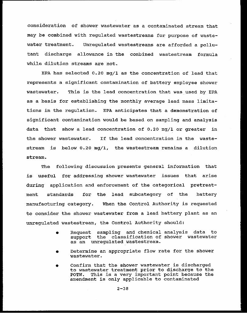
consideration of shower wastewater as a contaminated stream that
may be combined with regulated wastestreams for purpose of waste-
water treatment. Unregulated wastestreams are affo+ded a pollu-
tant discharge allowance in the combined wastestream formula
while dilution streams are not.
EPA has selected 0.20 mg/1 as the concentration of lead that
represents a significant contamination of battery employee shower
wastewater. This is the lead concentration that was used by EPA
as a basis for establishing the monthly average lead mass limita
tions in the regulation. EPA anticipates that a demonstration of
significant contamination would be based on sampling and analysis
data that show a lead concentration of 0.20 mg/l or greater in
the shower wastewater. If the lead concentration in the waste-
stream is below 0.20 mg/1, the wastestream remains a dilution
stream.
The following discussion presents general information that
is useful for addressing shower wastewater issues that arise
during application and enforcement of the categorical pretreat-
ment standards for the lead subcategory of the battery
manufacturing category. When the Control Authority is requested
to consider the shower wastewater from a lead battery plant as an
unregulated wastestream, the Control Authority should:
• Request sampling and chemical analysis data to support the classification of shower wastewater as an unregulated wastestream.
• Determine an appropriate flow rate for the shower wastewater.
• Confirm that the shower wastewater is discharged to wastewater treatment prior to discharge to the POTW. This is a very important point because the amendment is only applicable to contaminated
2-38
shower wastewater discharged to wastewater treatment. Shower wastewater discharged directly to the POTW is classified as a sanitary wastestream.
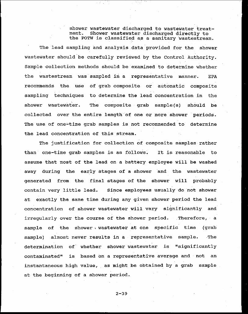
The lead sampling and analysis.data provided for the shower
wastewater should be careful~y reviewed by the Control Authority.
Sample collection methods should be.examined to determine whether
the wastestream was sampled iri a :representative manner. EPA
recommends the use of grab composite or automatic composite
sampling techniques to determine the lead concentration in the
shower wastewater. The composite grab sample(s) should be
collected over the entire lengthof one or more shower periods.
The use of one-time grab samples is not recommended to determine
the lead concentration of this stream.
The justification for collection of composite samples rather
than one~time grab samples is as follows. It is reasonable to
assume that most of the lead on a battery employee will be washed
away during the early stages of a shower and the wastewater
generated from the final stages of the shower will probably
contain very little lead. Since employees usually do not shower
at exactly the same time during any given shower period the lead
concentration of shower wastewater ,will vary significantly and
irregularly over the course of the shower period. Therefore, a
sample of the shower 1 wastewater at one specific time (grab
sample) almost never results in a representative sample. The
determination of whether shower wastewater is "significantly
contaminated" is based on a representative average and not an
instantaneous high value, as might be obtained by a grab sample
at the beginning of a shower period ..
2-39

EPA also recommends that plant specific sampling data be
required for employee shower wastewater since lead concentrations
may vary from plant to plant. This recommendation is based on
the premise that employees who work in areas with higher lead
dust exposure levels carry more lead into the shower area than
employees who work in areas with lower exposure levels. Since no
two plants have exactly the same exposure levels for all
employees, the amount of lead introduced into shower wastewater
will vary from plant to plant. In addition, the OSHA standards
only require battery employees working in areas with exposure 3
levels in excess of 50 mg/m of air to shower. However, at some
battery plants, showers are also provided for employees exposed 3
to less than 50 mg/m . The shower wastewater at these plants
should contain lower lead concentrations than the wastewater from
plants where showers are only provided for employees exposed to 3
lead levels in' excess of 50 mg/m . Therefore, plant specific
sampling data should be used to demonstrate the contamination of
shower wastewater.
The sample point location for the employee shower wastewater
should also be reviewed by the Control Authority. The most
desirable sample point location is the drain from the employee
shower area. The sample should be coll~cted directly from the
drain pipe, if possible, or by partially blocking the drain to
allow for sampling of the wastewater accumulated around the drain
area.
The Control Authority· must also determine an appropriate
flow range for the shower wastewater. A reasonable flow range is
2-40
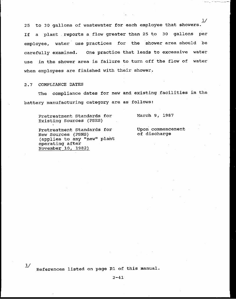
1/ 25 to 30 gallons of wastewater for each employee that showers.-
If a plant reports a flow greater than 25 t;o 30 gallons per
employee, water use practices for the shower area should be
carefully examined. One practice that leads to excessive water
use in the shower area is failure to.turn off the flow of water
when employees are finished with their shower.
2.7 COMPLIANCE DATES
The compliance dates for new and existing facilities in the
battery manufacturing category are as follows:
Pretreatment Standards for Existing Sources (PSES)
Pretreatment Standards for New Sources (PSNS) (applies to any "new" plant operating after November 10, 1982)
March 9, 1987
Upon commencement of discharge
References listed on page Rl of this manual.
2-41'

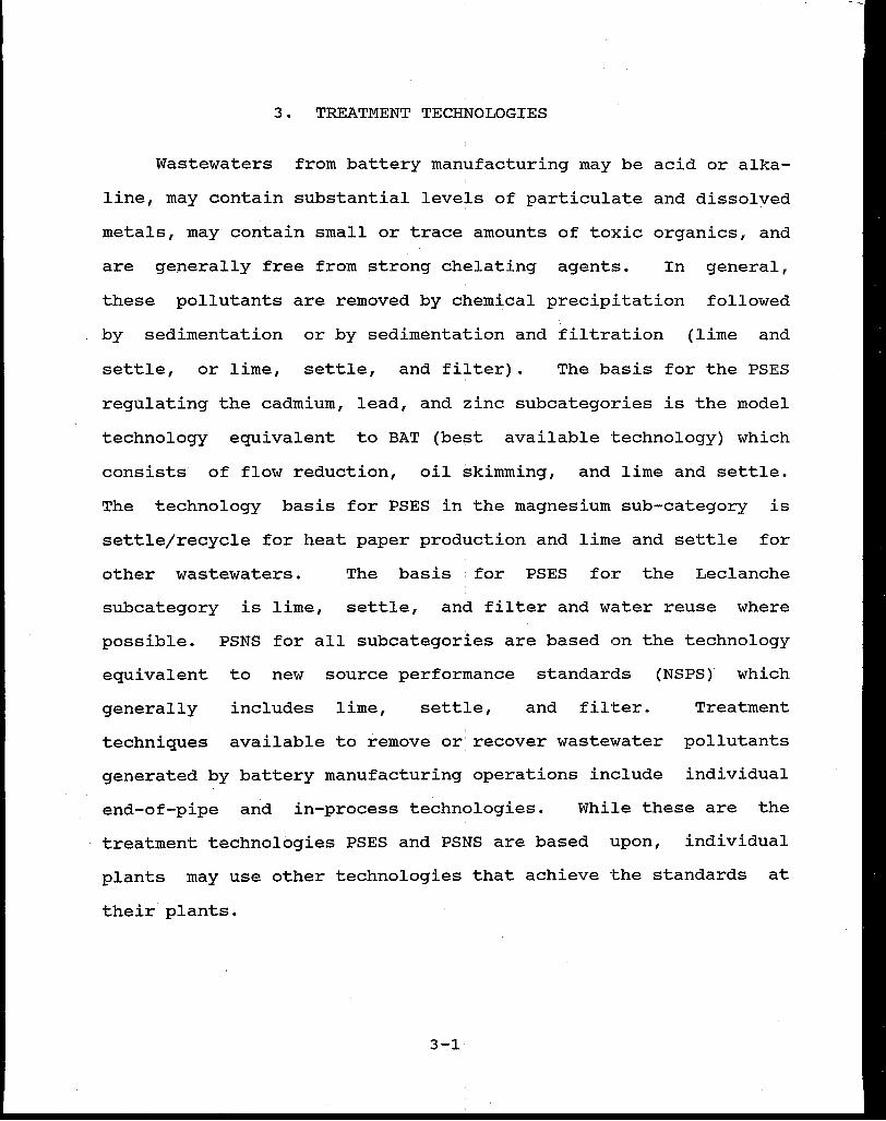
3. TREATMENT TECHNOLOGIES
Wastewaters from battery manufacturing may be acid or alka
line, may contain substantial levels of particulate and dissolved
metals, may contain small or trace amounts of toxic organics, and
are generally free from strong chelating agents. In general,
these pollutants are removed by chemical precipitation followed
by sedimentation or by sedimentation and filtration (lime and
settle, or lime, settle, and filter). The basis for the PSES
regulating the cadmium, lead, and zinc subcategories is the model
technology equivalent to BAT (best available technology) which
consists of flow reduction, oil skimming, and lime and settle.
The technology basis for PSES in the magnesium sub-category is
settle/recycle for heat paper production and lime and settle for
other wastewaters. The basis : for PSES for the Leclanche
subcategory is lime, settle, and filter and water reuse where
possible. PSNS for all subcategories are based on the technology
equivalent to new source performance standards (NSPS) which
generally includes lime, settle, and filter. Treatment
techniques available to remove or· recover wastewater pollutants
generated by battery manufacturing operations include individual
end-of-pipe and in-process technologies. While these are the
treatment technologies PSES and PSNS are based upon, individual
plants may use other technologies that achieve the standards at
their plants.
3-1

3.1 END-OF-PIPE TREATMENT TECHNOLOGIES
The major end-of-pipe technologies for treating battery
manufacturing wastewaters are: oil skimming, chromium reduction,
chemical precipitation of dissolved metals, settling of suspended
solids, pressure filtration, and granular bed filtration. Al
though not considered a major treatment technology for the
battery manufacturing category, membrane or polishing filtration
is often used following precipitation and sedimentation for more
consistent metals removal.
Skimming is used in battery manufacturing to remove free oil
used as a preservative or forming lubricant for various metal
battery parts and in lubricants used for drive mechanisms and
other machinery. Skimming removes pollutants with a specific
gravity less than water and is often found in conjunction with
air flotation or clarification to increase its effectiveness.
Common skimming mechanisms include the rotating drum type, a belt
type skimmer (which pulls a belt vertically through the water
thereby collecting oil), and API separators (which skim a
floating oil layer from the surface of the wastewater).
Chemical reduction of chromium is used in battery
manufacturing for treating chromium-bearing wastewater, primarily
from heat paper production in the calcium, lithium and magnesium
subcategories. The treatment of hexavalent chromium involves
reducing the hexavalent chromium to its trivalent form and
subsequent removal with a conventional precipitation-solids
removal system. Reduced chromium is removed from solution in
conjunction with other metallic salts by alkaline precipitation.
3-2
In most cases, gaseous sulfur dioxide is used as the reducing
agent.
Chemical precipitation, followed by sedimentation,
filtration, or centrifugation, is used in battery manufacturing
for removal of dissolved metals. Chemical precipitation involves I
adding a reagent to wastewater that will transform dissolved
metals to a non-dissolved state, permitting them to be removed by
settling, filtration or centrifug~tion. Reagents commonly used
are:
1) Alkaline compounds, such as lime or sodium hydroxide, precipitate metals as hydroxides;
2) Soluble sulfides, such as hydrogen sulfide or sodium sulfide, and insoluble sulfides such as ferrous sulfide, precipitate metals as·sulfides;
3) Ferrous sulfate or zinc sulfate precipitate cyanide as a ferro or zinc'ferricyanide complex;
4) carbonates precipitate metals directly as carbonates,and carbon dioxide converts hydroxides to carbonates.
The performance of chemical precipitation depends on the
following: maintenance of an appropriate pH (usually alkaline) I
throughout the precipitation rea9tion and subsequent settling;
the addition of a sufficient exce~s of treatment ions to drive
the precipitation reaction to completion; the addition of an
adequate supply of sacrificial ions (such as aluminum or iron) to
ensure precipitation and removal of specific target ions; and
effective removal of the precipitated solids using appropriate
solids removal technologies.
settling and clarification are used in battery manufacturing
to remove precipitated metals. Settling removes solid particles
from a liquid matrix by gravitational force. Settling is
3-3'

accomplished by . reducing the velocity of the feed stream in a
large volume tank or lagoon s~ that gravitational settling can
occur. Settling is most often preceded by chemical precipitation
which converts dissolved pollutants to a solid form and by
coagulation of suspended precipitates into larger, faster
settling particles (using coagulants or polyelectrolytic floccu
lants).
Pressure filtration is used in battery manufacturing for
sludge dewatering and for direct removal of precipitated and
other suspended solids from wastewater. Pressure filtration
works by pumping the water through a filter material which is
impenetrable to the solid phase thus separating the solids from
the water.
Granular bed filtration using filter media such as silica
sand, anthracite coal, and garnet supported by gravel are common
ly used to remove suspended solids and colloidal particles.
Wastewater treatment plants often use granular bed filters for
polishing after clarification, sedimentation, or similar opera
tions. The classic granular bed filter operates by gravity flow,
although pressure filters are also widely used.
3.2 IN-PROCESS CONTROL TECHNOLOGIES
In-process control technologies are intended to reduce or
eliminate the amount of pollutants or the volume of wastewater
requiring end-of-pipe treatment thereby improving the quality of
the effluent discharge. The in-process technologies which are
applicable to most battery manufacturing subcategories discussed
here are waste segregation, water recycle and reuse, water use
3-4
reduction, process modification, and plant maintenance and good
housekeeping. Specific applicat~on of these techniques varies
among the battery manufacturing subcategories and some apply only
to specific processing steps. Additional details are in Section
VII of the final technical devel~pment documents for battery
manufacturing.
Waste segregation of multiple process wastewater streams
having significantly different chemical characteristics may lead
to reductions in treatment costs and pollutant discharges. Bat-
tery manufacturing commonly produces waste streams with high
concentrations of toxic metals, containing primarily suspended
solids, and others that are quite dilute. Separation of these
individual process wastestreams may improve the quality of the
effluent discharge since treatment of more concentrated waste-
streams is usually more efficient than treatment of dilute
streams. Similarly, separation of noncontact cooling water from
process wastewater prevents dilution of the process wastes and
maintains the purity of the noncontact stream for subsequent
reuse or discharge.
Wastewater recycle and reuse are frequently possible wi.thout '
treatment or with minimum treatment of the wastewater, and there-
fore are effective in reducing pollutant discharges and overall
treatment costs. Recycle applies to the return of process waste-
water usually after treatment to the process or processes from
which it originated, and reuse applies to the use of wastewater
from one process into another process. The most frequently
recycled wastestreams include air pollution control scrubber
discharges, and wastewater from equipment and area cleaning. In
addition, wastewater from some product rinsing operations and
contact cooling waters are available for recycle or reuse.
Water use reduction includes reducing the volume of waste
water discharge by simply eliminating excess flow and unnecessary
water use. Often this can be accomplished by employing automatic
shutoff valves or manual controls to turn off water flows when
production units are inactive and by implementation of more
effective water use in some process operations, particularly in
rinsing operations and in equipment and area cleanup. Rinsing
efficiency can be increased by the use of multi-stage and
countercurrent cascade rinsing. Additional reduction in process
wastewater discharge may also be achieved by the substitution of
dry air pollution control devices such as baghouses for wet
scrubbers where the emissions requiring control are amenable to
these techniques.
Process modifications deal with process alternatives which
significantly affect the quantity and quality of wastewater
produced. In general, changes in electrolyte addition techniques
and changes in electrode formation processes are process changes
found most frequently in the battery manufacturing category. In
addition, changes in amalgamation procedures and improvements in
process control to reduce rework requirements are viable
techniques to reduce wastewater discharges. Most process modifi
cations to reduce pollutant discharges are specific to individual
subcategories; however, one process modification applicable to
several subcategories is the substitution of alternative formula
tions for cell wash materials containing chromate and cyanide.
3-6
This substitution reduces or eliminates these pollutants from the
process wastewater.
Plant maintenance and good housekeeping practices can signi
ficantly reduce pollutant loadings at battery manufacturing
plants due to the large quantities of toxic materials used as
active materials in battery electrodes. These materials are
handled at battery manufacturing plants and may be spilled in
production areas. The water used in the cleaning of spills may
contribute significantly to wastewater discharges. Good house
keeping includes floor maintenance and treatment, preventing
leaks and spills, and cleaning up leaks and spills which cannot
be avoided as soon as possible.
3-7

4. REQUIREMENTS OF THE GENERAL PRETREATMENT REGULATIONS
4.1 INTRODUCTION
This section provides a brief overview of the General Pre-
treatment Regulations for Existing and New Sources (40 CFR Part
403) and identifies those provisions of the regulations which
have a direct bearing on the application and enforcement of
categorical pretreatment standards for the battery manufacturing
category.
The General Pretreatment Reguiations (40 CFR 403) establish
the framework and responsibilities for implementation of the
' National Pretreatment Program. T~e effect of these regulations
is essentially three-fold. First, they establish general and
specific discharge prohibitions as required by sections 307(b)
and (c) of the Clean Water Act. The general and specific
prohibitions are described in 40 CFR Section 403.5 of the General I
Pretreatment Regulations and apply to all nondomestic sources
introducing pollutants into a POTW whether or not the source is
subject to categorical pretreatment standards.
Second, these regulations establish an administrative
mechanism to ensure that National Pretreatment Standards
(prohibited discharge standards and categorical pretreatment
standards) are applied and enforced upon industrial users.
Approximately 1,500 POTWs are required to develop locally
administered pretreatment programs to ensure that nondomestic
users comply with applicable pretreatment standards and require-
ments.
4-1
Third, and most importantly for the purposes of this
guidance manual, the General Pretreatment Regulations contain
provisions relating directly to the implementation and enforce
ment of the categorical pretreatment standards. Provisions
governing basic reporting requirements, local limits, compliance
monitoring activities, and the procedures associated with
categorical determinations are set out in the regulations. POTW
representatives are referred to 40 CFR Part 403 for specific
language and requirements.
EPA is considering making a number of changes to the General
Pretreatment Regulations. These changes will affect some of the
provisions of the pretreatment regulation discussed in this sec
tion including the following:
• Baseline monitoring reports
• Report on compliance
• Periodic reports on continued compliance
The anticipated changes could alter the guidance in this
section. Therefore, the reader is advised to keep abreast of
changes to the General Pretreatment Regulations.
4.2 CATEGORY DETERMINATION REQUEST
An existing industrial user (IU) or its POTW may request
written certification from EPA or the delegated State specifying
whether or not the industrial user falls within a particular
industry subcategory and is therefore subject to a particular
categorical pretreatment standard. Although the deadline for
4-2

submitting a categorical determination request by existing
industrial users subject to the battery manufacturing categorical
pretreatment standards has passed, a new industrial user may
request this certification for a category determination anytime
.prior to commencing its discharge. Similarly, a POTW may request
the certification on behalf of .the IU. Requests should be
directed to the EPA Regional Water Management Division Director
or the state Director as appropriate using the procedures set out
in 40 CFR 403.6(a). Additional assistance in determining the
proper category for wastewaters ·from such operations may be
obtained by contacting the Industrial Technology Division at U.S.
EPA Headquarters.
4.3 MONITORING AND REPORTING REQUIREMENTS OF THE PRETREATMENT REGULATIONS
GENERAL
In addition to the requirements contained in the battery i I
manufacturing categorical pretreatment standards, battery manu-
f acturers discharging to POTWs · must fulfill the reporting
requirements contained in 40 CFR S:ection 403.12 of the General
Pretreatment Regulations. These requirements include the submis-
sion of a baseline monitoring report, compliance schedule prog-
ress reports (when necessary), periodic compliance reports and
notices of slug loading, as well as a 3 year record-keeping
requirement. Each of these reporting requirements is briefly
summarized below.
4.3.1 Baseline Monitoring Reports
All industrial us.ers subject· to categorical pretreatment
standards must submit a· baseline monitoring report (BMR) to the
4-3
Control Authority. The purpose of the BMR is to provide
information to the Control Authority to document the industrial
user's current compliance status with a categorical pretreatment
standard. The Control Authority is defined as the POTW if it has
an approved pretreatment program, the state if the state has an
approved state pretreatment program or the EPA regional off ice if
neither the POTW or state have approved pretreatment programs.
Additional guidance on BMR reporting is available from the state
or EPA regional pretreatment coordinator (see the list of
guidance manuals in the References section of this document). A
complete listing of current EPA and state pretreatment
coordinators is provided in Appendix c.
BMR Due Dates
Section 403.12(b) requires that BMRs be submitted to the
Control Authority within 180 days after the effective date of a
newly promulgated categorical pretreatment standard or 180 days
after the final administrative decision made upon a categorical
determination request (see section 4.2 above), whichever is
later. The BMR due date for existing facilities in the battery
manufacturing category was October 20, 1984.
BMR Content
A BMR must contain the following information as required by
403.12(b).
1. Name and address of the facility, including names of operator(s) and owner(s).
2.
3.
List for
of all environmental control permits held by the facility.
or
Brief description of the rate and SIC code for conducted, including a
4-4
nature, average production each of the operation(s)
schematic process diagram

which indicates points of discharge from the regulated processes to the POTW.
, 4. Average daily and maximum daily flow data (in gallons per day) for regulated process streams discharged to the municipal system. Flow measurements of other wastestreams will be necessary if application of the combined wastestream formula is anticipated (see section 4.4 below).
5. Identification of the applicable pretreatment standards for each regulated process wastestream and the results of measurements of flow rates and pollutant concentrations (or mass where required by the standard or the Control Authority)~ The mass of pollutants in the wastestreams must be expressed in terms of daily average and daily maximum.values. , Analytical methods used must be in accordance with the .procedures contained in 40 CFR Part 136, or as otherwise directed and approved by EPA. Sampling is to be undertaken using a flow proportional composite method whenever possible. Otherwise, where compos~te sampling is not feasible, grab samples are appropriate. Samples must be representative of daily operations. Where the flow of the regulated stream being sampled is less than or equal to 250,000 gallons per day, ·the industrial user must take three samples within a two week period. Where the flow of the stream is greater than 250,000 gallons per day, the industrial user must take six samples within a two week period. If other wastewaters are mixed with wastewater from the regulated process, the industrial user should measure flows and concentrations of the appropriate wastestreams to allow use of the combined wastestream formula (see section 4.4 below). Proposed revisions to 40 CFR Part 403 may alter the number of samples required to be submitted in a BMR. .
6. The BMR must include' the dates, times and sampling locations and the analytical methods used to derive the testing results.
7. Finally, an authorized representative of the IU (see 40 CFR Section 403.12 (k)) must certify as to whether the facility is currently meeting the categorical pretreatment standards. Ih the event the standards are not being achieved, the; certification must contain a compliance schedule whi9h identifies the additional operation and maintenan~e measures and/or abatement technology necessary to bring the IU into compliance and the timetable for completing these actions. The final date for completing these actions and achieving compliance must not exc$ed the compliance deadline established by the standard. IUs are referred to 40
4-5

CFR Section 403.12(b) (7) and (c) for more specific instructions on preparing this compliance schedule.
4.3.2. Compliance Schedule Progress Report
In the event the IU certifies that it is not meeting the
categorical standard on a consistent basis a compliance schedule
must be submitted with the BMR that describes the actions the IU
will take and a timetable for completing those actions to achieve
compliance with the standard. The completion date in the
schedule must not be later than the compliance date established
for the particular categorical standard. The compliance
schedule must contain increments of progress and dates for
completion of each increment. Further, no increment shall exceed
nine months.
Within 14 days of each date in the compliance schedule, the
user must submit a progress report to the control Authority. The
compliance schedule progress report must indicate whether or not
it complied with the increment of progress intended to be met.
If the target date was not met, the report must indicate a
revised date on which it expects to comply, the reasons for the
delay and the steps to be taken to return to the schedule
established in the BMR.
4.3.3 Report On Compliance
Within 90 days of the final compliance date for the battery
manufacturing pretreatment standards, or in the case of a new
source, following commencement of the introduction of wastewater
into the POTW, any industrial user subject to these standards
must submit to the Control Authority a compliance report that
4-6
indicates whether or not applicable pretreatment standards are
being met on a consistent basis. :The report must indicate the
nature and concentration of all regulated pollutants in the
facility's regulated process wastestreams; the average and maxi
mum daily flows of the regulated streams; and contain a statement
as to whether compliance is consistently being achieved, and if
not, what additional operation and maintenance or pretreatment is
necessary to achieve compliance (see 40 CFR Section 403.12(d)).
4.3.4 Periodic Reports On Continued Compliance
All industrial users subject to the battery manufacturing
pretreatment standards must submit a bian;nual "periodic
compliance report" during the months of June and December unless
required more frequently by the Control Authority. The Control
Authority may change the months during which the reports must be
submitted. The report shall indicate ·the precise nature and mass
(and concentration if required by the Control Authority) of the
regulated pollutants in its discharge to the POTW during the
reporting period and the average ~nd maximum daily flow rates.
The methods used to sample and analyze the data, and a certi
fication that the methods conformed to those methods outlined in
the regulations should be included in the report.
Section 403.12(e)).
4.3.5 Notice Of Slug Loading
(see 40 CFR
Section 403.12(f) requires industrial users to notify the
POTW immediately of
pollutant,
system at
including
any slug loading (i.e. discharge of
oxygen demanding pollutants, to the
any
POTW
a flow rate or pollutant
4-7
concentration which might

cause interference with the POTW.)
4.3.6 Monitoring And Analysis To Demonstrate Continued Compliance
Section 403.12(g) states that industrial user reports must
contain the results of sampling and analysis of the user's
discharge, but does not prescribe any particular frequency of
monitoring. The battery manufacturing pretreatment standards
also do not establish monitoring frequency. Therefore, the
appropriate Control Authority must .establish the monitoring fre
quency to adequately demonstrate that indirect dischargers sub-
ject to these pretreatment standards are in compliance with the
applicable standards. EPA has issued guidance on suggested moni-
toring frequencies for the first year until sufficient baseline
data are collected (see Pretreatment Compliance Monitoring and
Enforcement Guidance, July 1986).
Sampling and analysis shall be in accordance with the
procedures established in 40 CFR Part 136. When Part 136 techni-
ques are not available or are inappropriate for any pollutant,
sampling and analysis shall be conducted in accordance with
procedures established by the Control Authority or using any
validated procedure. However, all procedures for sampling and
analysis not included in Part 136 must be approved in advance by
EPA.
4.3.7 Signatory Requirements For Industrial User Reports
All reports submitted by industrial users (BMR, Initial
Report on Compliance, and Periodic Reports, etc.) must be signed
by an authorized representative in accordance with 40 CFR Section
4-8
403 .12 (k) . Note that false statements or misrepresentations in
the aforementioned reports are punishable by a fine of not more
than $10,000 or by imprisonment for.up to 2 years, or by both
under Section 309(c) (4) of the CWA.
4.3.8 Recordkeeping Requirements
Records of all· sampling activities required under the
regulations above must include dates, exact place(s), methods and
times as well as identifying the person(s) taking the sample. In
addition, testing· records must indicate the dates and person(s)
performing the analysis as well as the analytical techniques used
and the results thereof. These records shall be maintained for a
minimum of three years (see 40 CFR Section·403.12(n) (2) and shall
be available for inspection and copying by the Control Authority.
4.4 APPLICATION OF THE COMBINED WASTESTREAM FORMULA
The Combined Wastestream Formula (CWF) (40 CFR section
403.6(e)) is a mechanism for calculating appropriate discharge
limitations for combined wastestreams. The CWF was developed to
account for the dilutional effect of mixing one regulated
wastestream with other regulated, unregulated, or dilution
streams prior to treatment. The following definitions and condi-
tions are important to the proper use of the CWF.
Definitions
• Regulated Process Wastestream - an industrial process wastestream regulated by national categorical pretreat-ment standards. ·
• Unregulated Process Wastestream - an i11dustrial process wastestream that is not regulated by a categorical pretreatment standard and· is not a dilute wastestream (see below) .
4-9
• Dilute Wastestream - Boiler blowdown, noncontact cooling water, and sanitary wastewater (unless regulated by the categorical pretreatment standard). The Control Authority has discretion to classify boiler blowdown and noncontact cooling water as unregulated wastestreams when these streams contain a significant amount of a regulated pollutant, and combining them with regulated process wastewaters will result in a substantial reduction of that pollutant (see 12 ERC 1833 and 40 CFR Part 403).
Note: These definitions capply to individual pollutants. Therefore a wastestream from a process may be regulated for one pollutant and unregulated for another.
• Mass-based Production Related Standard - a standard setting forth the quantity (mass) of a pollutant allowed to be discharged per each defined unit of production. Usually for battery manufacturing expressed in mg/kilogram of metal used or applied (lb/million pounds of metal used or applied).
• Mass-based Limit - a limit setting forth the quantity (mass) of a particular pollutant which may be discharged in a specific wastestream. This is derived from the mass-based production related standard and is usually expressed in mg/day (lb/day).
• Concentration-based Limit - a limit relative strength of a pollutant in usually expressed in mg/l (lb/gal).
CWF Conditions
based on the a wastestream,
The regulations specify that the following conditions must
be met by a municipality and its industries when applying the
CWF:
• Alternative discharge limits calculated in place of a categorical pretreatment standard must be enforced as categorical pretreatment standards themselves.
• Calculation of alternative limits must be performed by the Control Authority (generally the POTW) or by the industrial user with written permission from the Control Authority.
• Alternative regulated processes.
limits pollutants
must in
4-10
be established each of the
for all regulated

• The Control Authority should use mass limits, but use equivalent concentration limits when production based mass standards are provided by applicable categorical pretreatment standard.
may only the
• Both daily maximum and long-term average (usually monthly) average alternative limits must be calculated for each regulated pollutant.
• An industrial user operating under an alternative limit derived from the CWF must immediately report any significant or material chang~s in the regulated, unregulated or dilution wastestreams or production rates to the Control Authority.
• If a facility institutes process changes or production rates change and these changes warrant, the Control Authority may recalculate the alternative limits at its discretion or at the request of the industrial user. The new alternative l.imits will be calculated within 30 days of receiving notice of the change(s).
• The Control Authority may impose stricter alternative limits, but may not impose alternative limits that are less stringent than the calculated alternative limits.
• A calculated alternative limit cannot be used if it results in a discharge limit below the analytical detection level for that pollutant. If a calculated limit is below the detection limit, the IU must either: 1) not combine the dilute streams before they reach the combined treatment facility, or 2) segregate all wastestreams entirely.
• The categorical pretreatment standards for the regulated wastestreams wpich are applied to the CWF must be consistent in terms of the number of samples on which the standard is based.
Monitoring Requirements for Indµstrial Users Using the CWF
Self-monitoring requirements by an industrial user are
necessary to ensure compliance with the alternative discharge li-
mit. Because battery manufacturing pretreatment standards do not
include self-monitoring requirements, the Control Authority will
establish minimum self-monitoring requirements.
4-11
Application of the CWF
The actual combined wastestream formulas used with the
categorical pretreatment standards are presented in Table 4.1. It
is important to remember that when two or more regulated waste
streams from different regulated categories are mixed prior to
treatment, it is necessary to determine which pretreatment
regulation applies to each separate regulated wastestream. All
dilution and unregulated wastestreams need to be identified.
Table 4.2 presents an example of how the CWF is used to
calculate alternative limits for specific battery manufacturing
operations. The example applies to an integrated facility that
has operations regulated by the battery manufacturing categorical
pretreatment standards, as well as the metal finishing
categorical pretreatment standards.
Flow Weighted Averaging
The CWF is applicable to situations where wastewater streams
are combined prior to treatment. However, for facilities that
combine regulated process wastewaters with waters that are not
regulated after treatment but prior to monitoring by the Control
Authority (usually at the discharge point to the sanitary sewer),
a flow weighted average or more stringent approach must be used
to adjust categorical pretreatment standards. The flow weighted
averaging formula for use in these circumstances is set out in
Table 4.3.
4.5 REMOVAL CREDITS
A removal credit allows a POTW to provide its industrial
users with a credit (in the form of adjusted categorical pre-
4-12

TABLE 4.1
COMBINED WASTESTREAJ)1 FORMULAS
Alternative Mass Limit Formula
M = cwf
i=l
M x i
F F T D
N
2: F
i i=l
M alternative mass limit for the pollutant cwf
M categorical Pretreatment Standard mass limit for i the pollutant in regulated stream i
F average daily flow (at least 30 day average) of regulated i stream i
F average daily flow (at least 30 day average) of dilute D wastestream(s)
F average daily flow (at least 30 day average) through the T combined treatment facility (including regulated,
unregulated and dilute wastestreams)
N total number of regulated streams
4-13 -,
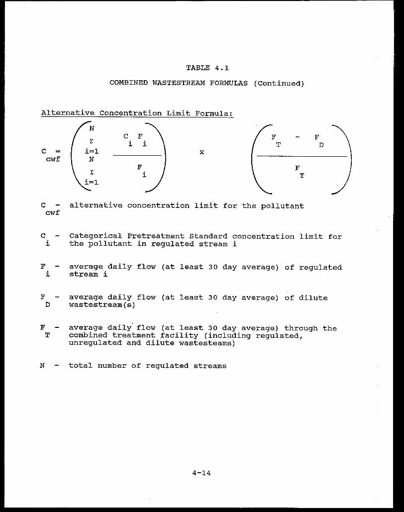
TABLE 4.1
COMBINED WASTESTREAM FORMULAS (Continued)
Alternative Concentration Limit Formula:
c F E i
c = i=l x cwf N
F E
F F T D
F T
C alternative concentration limit for the pollutant cwf
C Categorical Pretreatment Standard concentration limit for i the pollutant in regulated stream i
F average daily flow (at least 30 day average) of regulated i stream i
F average daily flow (at least 30 day average) of dilute D wastestream(s)
F average daily flow (at least 30 day average) through the T combined treatment facility (including regulated,
unregulated and dilute wastesteams)
N total number of regulated streams
4-14

TABLE 4-2
COMBINED WASTESTREAM FORMULA EXAMPLE CALCULATIONS
The following example provides calculations for determining alternate discharge limits for nickel using the combined wastestream formula. The following calculations assume combinations of various regulated and dilute wastestreams with the following characteristics. All wastestreams are combined prior to treatment.
Wastestream
Battery Manufacturing (Cadmium Subcategory)
Electrodeposited Anodes
Nickel Impregnated Cathodes
Metal Finishing (Nickel Plating)
sanitary
Waste stream ~
regulated
regulated
regulated
dilute
Flow (gpd)
2,000
13,000
15,000
50,000
The alternative discharge limit for nickel (daily maximum) at a cadmium battery manufacturing plant that also performs nickel plating and discharges sanitary wastewater is calculated as follows.
SOLUTION
Step 1: Determine the applicable nickel daily maximum limit for each wastestream.
4-15

TABLE 4-2
COMBINED WASTESTREAM FORMULA EXAMPLE CALCULATIONS (continued)
BATTERY MANUFACTURING
Cadmium Electrodeposited Anodes
Average Daily Production
Maximum Daily Limit for Nickel
Average Daily Water Use
Allowable Nickel Mass = 260 (67.49)
Nickel Impregnated Cathodes
Average Daily Production
Daily Maximum Limit for Nickel
Average Daily water Use
Allowable Nickel Mass = 230 (384)
Total Battery Manufacturing
= 260 kg/day of cadmium applied
= 67.49 mg/kg of cadmium applied
= 2,000 gpd
= 17,547 mg/day
= 230 kg/day of nickel applied
= 384 mg/kg of nickel applied
= 13,000 gpd
= 88,320 mg/day
Total Allowable Nickel Mass for Battery Mfg.
Average Daily water Use for Battery Mfg.
= 105,867 mg/day
= 15,000 gpd
Equivalent Concentration for Battery Mfg.
METAL FINISHING
Average Daily Production
Daily Maximum Limit for Nickel
Average Daily Water Use
= 1.86 mg/l for Nickel
= not required
= 3. 98 mg/l
= 15,000 gpd
Allowable Nickel Limit = 3.98 (15,000 x 3.785) = 225,965 mg/day
4-16
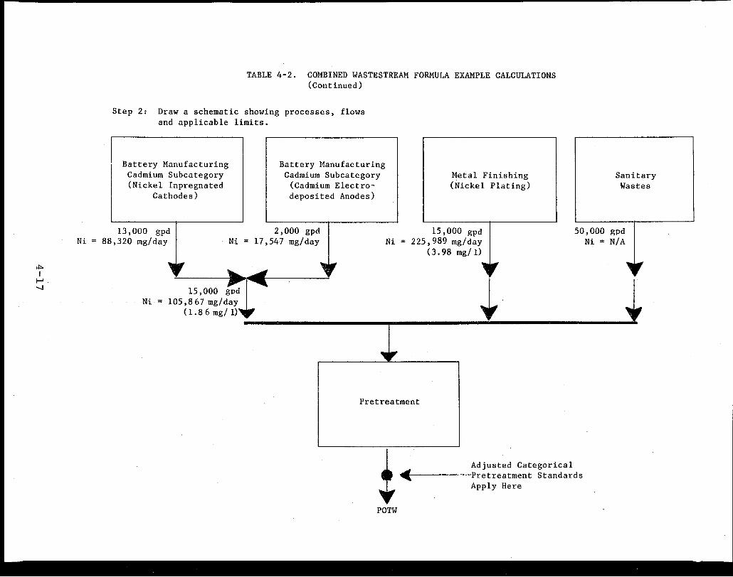
.!:» I ....,.
-....)
Ni
TABLE 4-2. COMBINED WASTESTREAM FORMULA EXAMPLE CALCULATIONS (Continued)
Step 2: Draw a schematic showing processes, flows and applicable limits.
Battery Manufacturing Cadmium Subcategory (Nickel Inpregnated
Cathodes)
Battery Manufacturing Cadmium Subcategory
(Cadmium Electrodeposited Anodes)
Metal Finishing (Nickel Plating)
Sanitary Wastes
13 ,000 gpd 88,320 mg/day
2,000 gpd Ni= 17,547 mg/day Ni
15,000 gpd 225, 989 mg/ day
(3. 98 mg/ 1)
50,000 gpd Ni = N/A
-Ni
,. ...... ~ 15,000 gpd ~l~
105,867 mg/day ( 1. 8 6 mg/ 1)
•
Pretreatment
;----41(· POTW
i
Adjusted Categorical Pretreatment Standards Apply Here

TABLE 4-2
COMBINED WASTESTREAM FORMULA EXAMPLE CALCULATIONS (continued)
Step 3: Using the combined wastestream formula (mass or concentration limit formula), substitute the appropriate values and calculate the adjusted limit.
a) Mass Limit Formula
F - F N T D
M ~ E Mi x cwf i=l N
E F i=l i
15,000 + 15,000 + 50,000 - 50,000 gpd Ni=
cwf 105,867 + 225,965 x ~~~~~~~~~~~~~~~~~~~
mg/day mg/day
Ni = 331,832 mg/day cwf
Ni = 0.332 kg/day cwf
b) Concentration Limit Formula
N E Ci Fi i=l
c = x cwf
N E Fi i=l
(1.86 mg/l x 15,000 gpd Ni=
cwf 15,000 gpd
15,000 + 15,000 +
F
+
+
T
15,000 + 15,000
15,000 + 15,000 gpd
F D
F T
3.98 mg/l x 15,000 gpd) x
15,000 gpd
50,000 50,000 gpd
+ 50,000 gpd
4-18
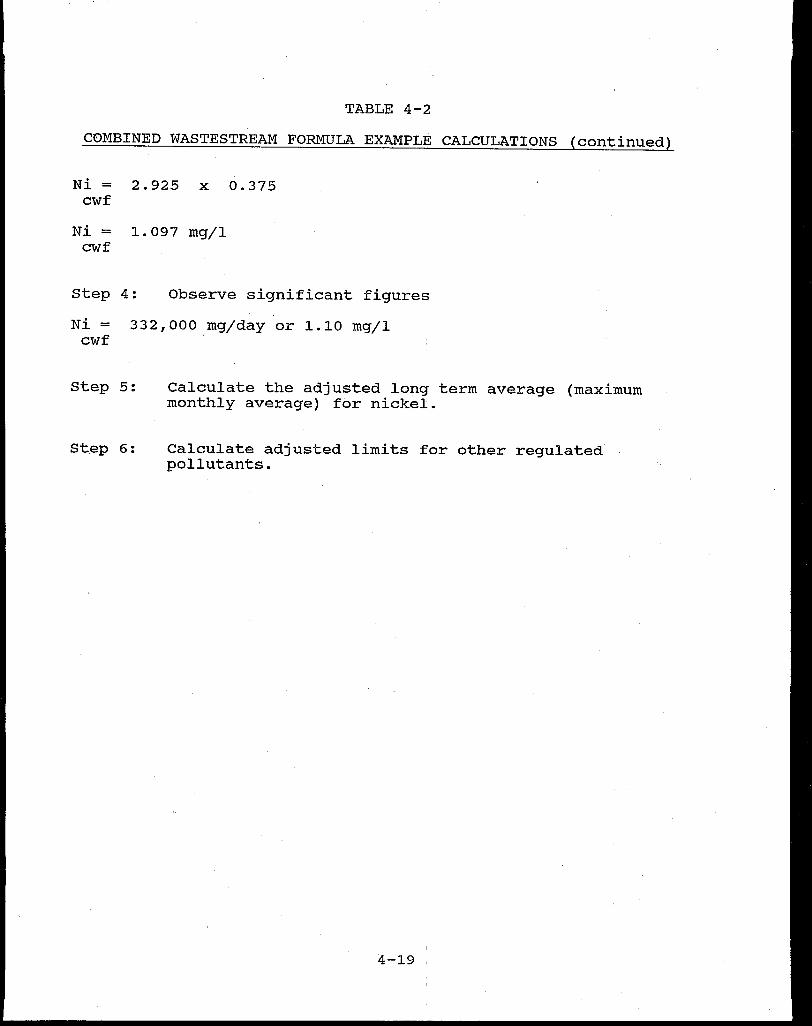
TABLE 4-2
C0MBINED WASTESTREAM FORMULA EXAMPLE CALCULATIONS (continued)
Ni = 2.925 x 0.375 cwf
Ni = 1.097 mg/l cwf
Step 4: Observe significant figures
Ni = 332,000 mg/day or 1.10 mg/l cwf
Step 5:
St.ep 6:
Calculate the adjusted long term average (maximum monthly average) for nickel.
Calculate adjusted limits for other regulated pollutants.
4-19 '
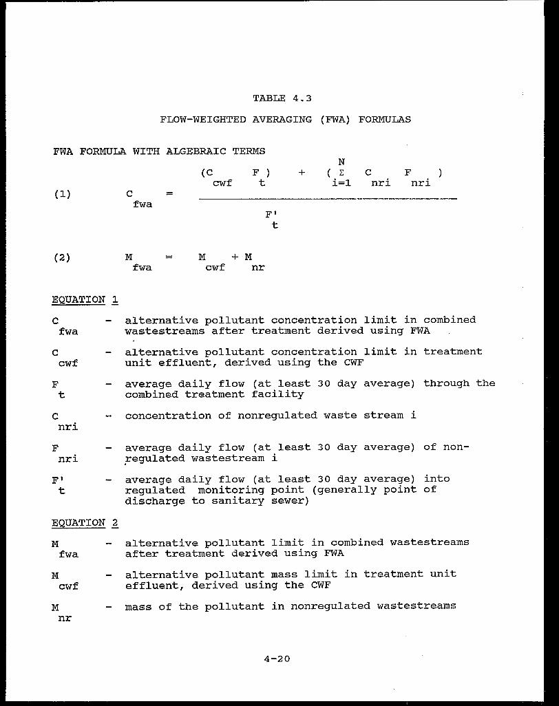
TABLE 4.3
FLOW-WEIGHTED AVERAGING (FWA) FORMULAS
FWA FORMULA WITH ALGEBRAIC TERMS
(1)
(2)
EQUATION 1
c f wa
c cwf
F t
c nri
F nri
F' t
EQUATION ~
M f wa
M cwf
M nr
c = fwa
M = fwa
(C cwf
M + cwf
F ) t
F' t
M nr
N + ( E C F
i=l nri nri
alternative pollutant concentration limit in combined wastestreams after treatment derived using FWA
alternative pollutant concentration limit in treatment unit effluent, derived using the CWF
average daily flow (at least 30 day average) through the combined treatment facility
concentration of nonregulated waste stream i
average daily flow (at least 30 day average) of non~egulated wastestream i
average daily flow (at least 30 day average) into regulated monitoring point (generally point of discharge to sanitary sewer)
alternative pollutant limit in combined wastestreams after treatment derived using FWA
alternative pollutant mass limit in treatment unit effluent, derived using the CWF
mass of the pollutant in nonregulated wastestreams
4-20
treatment standards) for consistent removal of pollutants by the
POTW. Industrial users receiving such a credit are allowed to
discharge to the POTW greater quantities of regulated pollutants
than otherwise permitted by applicable categorical pretreatment
standards. Section 403.7 of the General Pretreatment Regulations
establishes the conditions under which a POTW can obtain
authorization to grant removal credits. Removal credits are
pollutant specific (i.e., may only be granted on a pollutant by
pollutant basis).
In order to qualify for removal credit authority a POTW must
satisfy the conditions set out in the regulations including a
demonstration of the POTW's ability to "remove" the pollutant in
question on a long term or consistent basis, that is, the removal
is not subject to significant seasonal variations. Removal
credits can only be granted for pollutants regulated by a
categorical pretreatment standard.
Approval for removal credits may not be granted if it will
cause the POTW to violate its NPDES permit. Other criteria
including compliance with water quality criteria and standards
and sludge disposal regulations must be satisfied as well. Even
though the POTW may be located in an NPDES State which has an
approved state pretreatment program~ final approval of the POTW's
request rests with EPA, unless EPA has granted or delegated final
approval authority to the state through a State/EPA Memorandum
of Agreement (MOA).
Note: The removal credits regulation promulgated on August 3,
1984 (49 FR 31212) was challenged as too lenient by an
4-21.

environmental group, the Natural Resources Defense council
(NRDC). The United States Court of Appeals for the Third circuit
ruled in favor of NRDC, concluding that EPA's 1984 removal credit
rule fails to meet the requirements mandated by Section 307 of
the Clean Water Act (NRDC v. EPA, 790 F.2 d 289 (3rd Cir 1986).
Although several parties petitioned the Supreme Court to review
the Third Circuit ruling, the Court denied the requests. Thus,
the Third Circuit decision became final.
In addition to the litigation described above, the
amendments to the Clean Water Act contain a provision which would
vacate one element of the Third Circuit's decision - the sludge
question - as it effects POTWs currently authorized to grant
removal credits (as of the date of enactment.) However, this
congressional reprieve would lapse on August 31, 1987, the date
the Agency is required to have final regulations addressing toxic
pollutants in municipal sludge. As a result of these complica
tions, no regulatory basis currently exists for the granting of
removal credits.
4.6 FUNDAMENTALLY DIFFERENT FACTORS (FDF) VARIANCE
A request for a fundamentally different factors variance is
a mechanism by which a categorical pretreatment standard may be
adjusted,
basis.
believes
making it more or less stringent, on a case-by-case
If an industrial user, a POTW, or any interested person
that the factors relating to a specific industrial user
are fundamentally different from those factors considered during
development of the relevant categorical pretreatment standard and
that the existence of those factors justifies a different
4-22
discharge limit from that specified in the categorical
pretreatment standard, then they may submit a request to EPA for
such a variance within 180 days after the effective date of the
standard (see 40 CFR Section 403.13).
Although EPA has no statutory basis for granting adjustments
to categorical pretreatment standards because a source is
' "fundamentally different", the U.S. Supreme Court has previously
recognized the FDF variance's legitimacy as an administrative
tool to address concerns with both direct and indirect
dischargers. In fact, in CMA v. NRDC, 53 LW 4193 (No. 83-1013,
2-27-85), the Court upheld EPA in a challenge to the Agency's
determination that under the appropriate. circumstances FDF
variances could be granted for ' toxic pollutants, otherwise
regulated by categorical pretreatment standards. For other court
decisions on FDF variances the reader is referred to E.I.
duPont de Nemours v. Train, 430 U.S. 112 (1977) and
EPA v. National Crushed Stone Assoc. 449 U.S. 64 (1980).
4.7 LOCAL LIMITS
Local limits are numerical pollutant concentration or mass-
based values that are developed by a POTW for controlling the
discharge of conventional, non-conventional or toxic pollutants
into its sewer systems. They differ from National Categorical
Pretreatment Standards in that categorical pretreatment standards
are developed by EPA and are based upon the demonstrated perfor
mance of available pollutant control technologies (for specific
categorical industries). These national technology-based catego-
rical standards do not consider local environmental criteria or
4-23

conditions, and are only developed to assure that each, point
source within a specified category meets a minimum discharge
standard which is consistent across the United states for all
POTWs.
Local limits, on the other hand, are developed to address
specific localized impacts and factors that are unique to the
POTW.
from:
Local limitations must be designed to protect the POTW
• Introduction of pollutants into the POTW which could interfere with its operation, including contamination of a POTW's sludge which would limit sludge uses or disposal practices.
• Pass-through of inadequately treated pollutants which could violate a POTW's NPDES permit or applicable water quality standards .!./
Local limits are required under 40 CFR Section 403.5 and must
be developed when it is determined that categorical pretreatment
standards are not sufficient to enable the POTW to prevent
interference and pass-through. For more information on the
minimum local limit requirements for POTWs with approved
pretreatment programs and the relationship between local limits
and categorical pretreatment standards, refer to the memorandum
signed by Rebecca Hanmer on August 5, 1985 entitled
Local Limit Requirements for POTW Pretreatment Programs. Copies
of this memorandum can be obtained from the EPA regional
pretreatment coordinators listed in Appendix C.
1/ The terms "pass through" and "interference" are defined more precisely in 40 CFR Section 403.3.
4-24

In addition to protecting against interference and pass-
through, local limits must be developed to protect·the POTW from
discharges that may result in:
• Fire or explosion
• Corrosion
• Obstruction of flow in sewers
• Excessive discharge of conventional pollutants
e Heat that may cause inter,f erence
EPA encourages local limits for volatile toxic substances to
protect worker health and safety as well.
To assist municipalities in developing defensible and
technically sound numerical effluent limitations, EPA has pre-
pared some general guidelines qn limit development in its
document Guidance Manual for POTW Pretreatment Program Develop-
ment dated October 1983. Appendix L of this document lists the
general methodology, required fo~ulas and typical environmental
criteria used to develop local limits. This manual is available
from EPA regional offices and NPDES states and should be careful-
ly followed when developing local limits. Although a detailed
discussion of local limits development is beyond the scope of
this document, the general methodology includes the following
five steps:
Step 1 -
Step 2 -
survey conditions of collection system and monitor sewer atmosphere to determine whether limits are necessary to prevent collection system hazards.
Determine the maximum raw waste loading to the headworks of the treatment plant (for each specific pollutant) that will assure that the POTW does not experience interference or pass-through
4-25
Step 3 - Calculate the allowable loading to the POTW subtracting the uncontrollable portion pollutant discharge to the POTW (from domestic infiltration/inflow sources) from the total waste loading value.
by of
and raw
Step 4 - Distribute the controllable loading to industrial users through an allocation process.
Step 5 - Derive results system.
specific local limits from the and from the survey of the
allocation collection
The above five-step process must be performed for each
pollutant which the POTW determines may need a specific local
limitation. As a general rule, the limit setting analysis should
be performed for all pollutants which are discharged to the POTW
in significant quantities. The POTW should identify pollutants
of concern through an evaluation of the POTW's industrial waste
survey. A procedure for evaluating industrial waste survey re-
sults is also included in the EPA guidance manual mentioned
earlier.
In addition, EPA has developed a computer software program
that incorporates the general methodology required to develop
local limits and alleviates a substantial amount of the tedious
calculations required to develop these limits. This computer
program has the following capabilities to aid the POTW in limit
development:
• Performs the four-step limit setting analysis on a microcomputer
• Supplements POTW data with "built-in" files containing data on industrial/municipal wastewater characteristics, POTW removal rates, and biological process inhibition data
• Allocates controllable pollutant loads using several different methodologies
4-26

POTWs may obtain information on this computer program by
contacting any of the ten EPA regional o.ffices. Instructions
will be provided on how to use the computer program as well as
how to access a computer system which supports it.
4-27

5. APPLICATION OF BATTERY MANUFACTURING CATEGORICAL PRETREATMENT STANDARDS
This section provides guidance to Control Authorities on how
to apply production-based standards. Production-based standards
are expressed in terms of allowable pollutant mass discharge per
unit of production (mg/kg). Direct application of this standard
would require the Control Authority to make direct measurements
of the flow of the regulated wastestreams and the corresponding
current production rate. Rather than measure the production rate
each time compliance monitoring: is performed, the Control
Authority may use equivalent mass or equivalent concentration
limits. A reasonable representation of the industrial facility's
actual production and actual flows are used to derive these
limits that are essentially equivalent to the production-based
standards. EPA recommends that long-term average production and
flow rates be determined based qn the examination of several
years (such as 5 years) of data. In some cases production may
have specific seasonal fluctuations. The Control Authority may
choose to issue a tiered permit (more than one standard based on
different production levels) if significant change in the long-
term average production is expected during the term of the
permit. Further guidance can be found in EPA's Guidance Manual
for the Use of Production Based Pretreatment Standards and the
Combined wastestream Formula.
An example of how to develop :mass equivalent limits and use
the combined wastestream formula (CWF) was presented in Section
4.4. Another example is provided to demonstrate the application
5~
of production based standards to a lead subcategory battery
plant, which many Control Authorities may encounter. Concepts
used in this example can be applied to the other battery subcate-
gories. If difficulties are encountered, the Control Authority
is encouraged to contact the EPA Industrial Technology Division
Project Officer for technical clarifications or the Permits Divi-
sion for pretreatment or permit clarifications. The example
demonstrates the development of equivalent concentration based
limits and the use of the combined wastestream formula (CWF) to
derive the alternative. discharge standard for the total plant.
The plant used in this example is a lead battery
manufacturing plant, producing automotive batteries, and a
secondary lead smelter. The regulated wastestreams from battery
manufacturing and smelting are combined with noncontact cooling
water and sanitary wastes prior to treatment. The plant also
discharges employee shower wastewater to treatment and plant
management contends that the employee shower wastewater is
contaminated with lead. They have requested that the Control
Authority classify the stream as an unregulated wastestream
instead of a dilution stream, and have provided sampling and
analysis data. Documentation for the shower wastewater is:
• The sample collected was multiple grabs composited over the entire length of one shower period
•
•
!/ Note:
Twenty-five employees collection period
showered during the sample
The total volume of water used during the sample collection period was 625 gallons (25 gallons/employee).!/
The usual volume of water per person per shower is 25-30 gallons. (See References on R-1).
5-2
• Analytical data showed a 0.25 mg/l lead concentration in the wastewater sample collected
• An average of 50 employees shower each day employees/day) .
(50
Based on .this information, the Control Authority classifies
the employee shower wastewater as ~n unregulated stream with a
11250 gpd flow (25 gallons/employee x 50 employees/day).
The alternative concentration ,limit for the total plant is
developed through the following successive steps.
Step 1 - Draw a simple process flow diagram showing all regulated
category (or subca~egory) process wastestreams and other
wastestreams that are combined prior to treatment (see
Figure 5.1) Determine appropriate production rates and
discharge flows for each regulated category.
Step 2 - Determine the mass limit for each regulated category
that is combined for treatment using the following
formula:
Mass limit = production-based standard (mg/kg)
x regulatory production rate (average or
other reasonable estimate) (kg/day).
For example, the maximum one day standard for lead for
open formation is 0.71 mg/kg of lead used and the
actual amount of lead used is 5000 kg/day. The mass
limit for the example plant is 3550 mg/day (0.71 mg/kg
x 5000 kg/day). Table s~1·displays these calculations
in a tabular format. Mass limits for the regulated
battery plant wastestreams were calculated using the
pretreatment standards shown in Appendix B of this
5-3
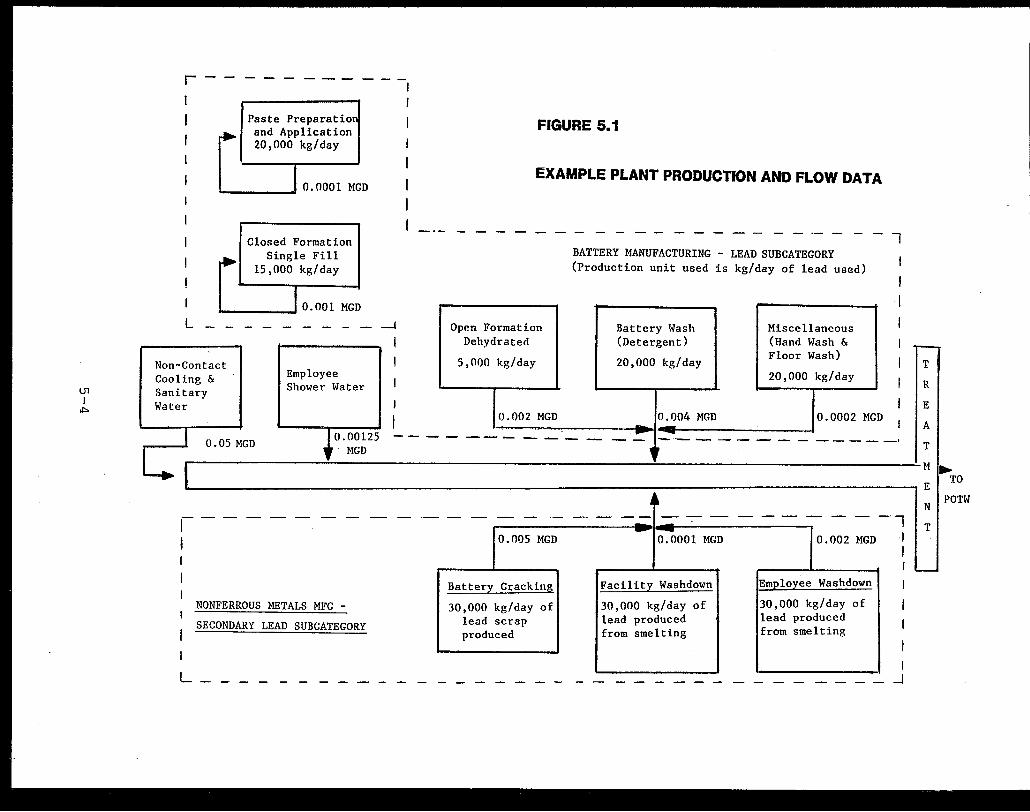
U1 I
ii»
r--------
I
Paste Preparatio and Application 20,000 kg/day
.__ ___ _, 0.0001 MGD
I
Closed Formation Single Fill
15,000 kg/day
I 0.001 MGD
L - -· - - - - - - - -I
Non-C Cool Sani Water
on tact ng & ary
Employee Shower Water
I I
I
J
I
FIGURE 5.1
EXAMPLE PLANT PRO,DUCTION AND FLOW DATA
-·- - - - - - -----------------1
Open Formation Dehydraterl
5,01)0 kg/day
0.002 MGD
BATTERY MANUFACTURING - LEAD SUBCATEGORY (Production unit used is kg/day of lead used)
Battery Wash Miscellaneous (Detergent) (Hand Wash &
20,000 kg/day Floor Wash)
20,000 kg/day
0.004 MGD 0.0002 MGD
I
I I
I I I I
1 • 0.00125 -------------=- -0.05 MGD ---- -- - - - _____ ,
MGD , '
,._
T
R
E
A
T
I Ml ~ TO
,-1
E
•• N - - - - - - - - - ·- - - - - -- - - -- - - - - - - - - - -,
I - - T
NONFERROUS METALS MFG -
SECONDARY LEAD SUBCATEGORY
0.005 MGD 0.0001 MGD 0.002 MGD :
I - I .__.
Battery Cracking
30,000 kg/day of lead scrap produced
Facility Washdown
30,000 kg/day of lead produced from smelting
Employee Washdown
30,000 kg/day of lead produced from smelting
I
L----------------------------------~~
POTW
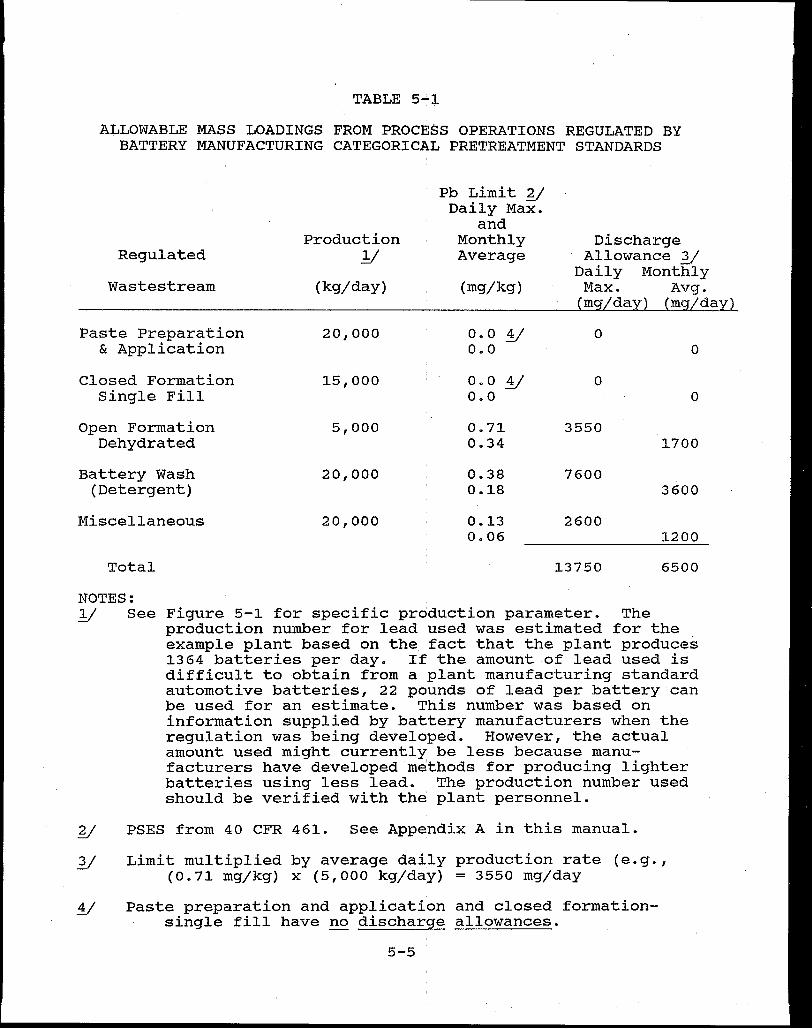
TABLE 5-"l
A~LOWABLE MASS LOADINGS FROM PROCESS OPERATIONS REGULATED BY BATTERY MANUFACTURING CATEGORICAL PRETREATMENT STANDARDS
Production Regulated .Y
Wastestream (kg/day)
Paste Preparation 20,000 & Application
Closed Formation 15,000 Single Fill
Open Formation 5,000 Dehydrated
Battery Wash 20,000 (Detergent)
Miscellaneous 20,000
Total
NOTES:
Pb Limit y Daily Max.
and Monthly Average
(mg/kg)
0.0 y o.o
0.0 y o.o
0.71 0.34
0.38 0.18
0.13 0.06
Discharge Allowance 3/
Daily Monthly Max. Avg.
(mg/day) (mg/day)
0 0
0 0
3550 1700
7600 3600
2600 1200
13750 6500
.Y See Figure 5-1 for specific production parameter. The production number for lead used was estimated for the example plant based on the fact that the plant produces 1364 batteries per day. If the amount of lead used is difficult to obtain from a plant manufacturing standard automotive batteries, 22 pounds of lead per battery can be used for an estimate. This number was based on information supplied by battery manufacturers when the regulation was being developed. However, the actual amount used might currently be less because manu- · facturers have developed methods for producing lighter batteries using less lead. The production number used should be verified with the plant personnel.
y PSES from 40 CFR 461. See Appendix A in this manual.
Limit multiplied by average daily production rate (e.g., (0.71 mg/kg) x (5,ooo kg/day) = 3550 mg/day
Paste preparation and application and closed formationsingle fill have no discharge allowances.
5-5
manual for the lead subcategory (page B-2 and B-3)
multiplied by the plant's regulatory production rate
(average or other reasonable estimate). Note from Figure
5-1 that the paste preparation and application and closed
formation single fill operations should not receive a
discharge allowance. Even if wastewaters from these
the battery operations were being discharged,
manufacturing pretreatment standard states "no discharge
allowance for process wastewater pollutants" for these
operations.
pollutants
This means that no discharge allowance
is allowed although a flow discharge may
for
be
allowed. The facility's smelter operations are regulated
by the nonferrous metals manufacturing categorical
pretreatment standards secondary lead subcategory. Three
of the facility's process operations, battery cracking,
facility washdown, and employee washdown, are regulated
by the nonferrous standards.
Mass limits for the secondary lead smelter wastestreams
were determined by using the standards provided in 40 CFR
421 for the secondary lead subcategory of the nonferrous
metals manufacturing category (See 49 FR 8740 March 8,
1984) multiplied by the plant's regulatory production rate
(Figure 5-1). Note that the facility washdown
wastestream receives zero discharge allowance (the
production-based standard is depicted as o.ooo mg/kg of
lead produced from smelting). These equivalent
mass limits are shown in Table 5-2. Once the
allowable mass loadings, as derived in Tables 5-1 and
5-6
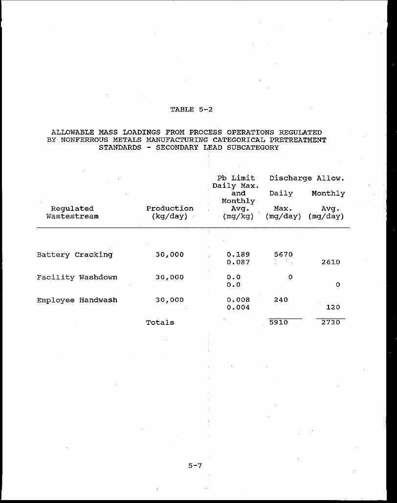
TABLE 5-2
ALLOWABLE MASS LOADINGS FROM PROCESS OPERATIONS REGULATED BY NONFERROUS METALS MANUFACTURING CATEGORICAL PRETREATMENT
STANDARDS - SECONDARY LEAD SUBCATEGORY
Regulated Wastestream
Battery cracking
Facility Washdown
Employee Hand wash
Production (kg/day)
30,000
30,000
30,000
Totals
5-7
Pb Limit : Daily Max. · and
Monthly Avg.
(mg/kg)
0.189 0.087
o.o o.o
0.008 0.004
Discharge Allow.
Daily Monthly
Max. Avg. (mg/day) (mg/day)
5670 2610
0 0
240 120
5910 2730
5-2, have
formula can
been calculated, the combined wastestream
be applied. Since both the battery and
nonferrous metals categorical pretreatment standards
are mass limitations, the appropriate form of the com
bined wastestream formula is the alternative mass limit
formula, previously presented in Table 4-1 of this
manual (see CWF Conditions in the discussion of the
CWF, Section 4.4).
Step 3 - Determine which wastestreams are regulated, unregulated
or dilution wastestreams. This classification along
with their respective flows is shown in Table 5-3.
Step 4 - Calculate a mass limit for the total plant using the
alternative mass limit formula in Table 4.1. The ap
plication of the alternative mass limit formula to the
example plant for the pollutant lead is presented
in Table 5-3. The mass limit as derived in Table 5-3
applies to the combined industrial plant discharge to
the POTW after wastewater treatment.
Step 5 - Calculate an equivalent concentration limit by dividing
the alternative mass limit by the average total plant
flow. (This step is shown in Table 5-3)
Step 6 - Follow the same procedure for calculating the monthly
average limit for lead as well as the daily maximum and
monthly average limits for all other regulated
pollutants.
In some cases, the POTW may wish to regulate other
pollutants not regulated by the battery manufacturing categorical
5-8
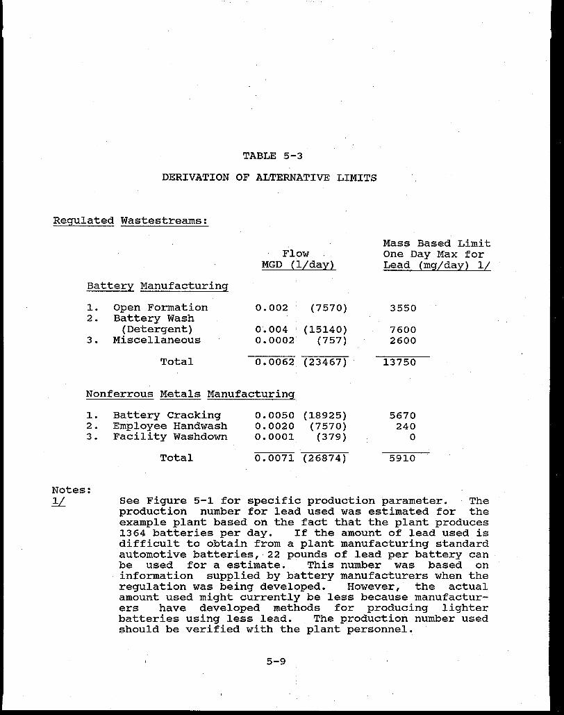
TABLE 5-3
DERIVATION OF ALTERNATIVE LIMITS
Regulated Wastestreams:
Battery Manufacturing
1. Open Formation 2. Battery Wash
(Detergent) 3. Miscellaneous
Total
Flow MGD (l/day)
0.002 (7570)
0.004 (15140) o. 0002' (757)
0.0062 (23467)
Nonferrous Metals Manufacturing:
1. Battery cracking 2. Employee Handwash 3. Facility Washdown
Total
0.0050 (18925) 0.0020 (7570) 0.0001 (379)
0.0071 (26874)
Mass Based Limit One Day Max for Lead (mg/day) 1/
3550
7600 2600
13750
5670 240
0
5910
Notes: .!L See Figure 5-1 for specific production parameter. The
production number for lead used was estimated for the example plant based on the fact that the plant produces 1364 batteries per day. ~f the amount of lead used is difficult to obtain from a plant manufacturing standard automotive batteries, 22 pounds of lead per battery can be used for a estimate. This number was based on information supplied by battery manufacturers when the regulation was being developed. However, the actual amount used might currently be less because manufacturers have developed methods for producing lighter batteries using less lead. The production number used should be verified with the plant personnel.
5-9
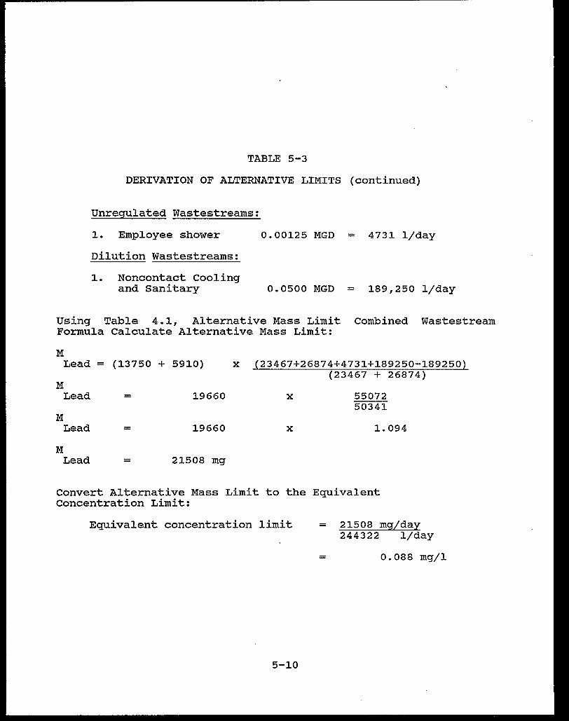
TABLE 5-3
DERIVATION OF ALTERNATIVE LIMITS (continued)
Unregulated Wastestreams:
1. Employee shower
Dilution Wastestreams:
1. Noncontact Cooling and Sanitary
0.00125 MGD = 4731 l/day
0.0500 MGD = 189,250 l/day
Using Table 4.1, Alternative Mass Limit Combined Wastestream Formula Calculate Alternative Mass Limit:
M Lead = (13750 + 5910)
M Lead
M Lead
M Lead
=
=
=
19660
19660
21508 mg
x (23467+26874+4731+189250-189250) (23467 + 26874)
x
x
55072 50341
1.094
Convert Alternative Mass Limit to the Equivalent Concentration Limit:
Equivalent concentration limit
5-10
= 21508 mg/day 244322 l/day
= 0.088 mg/l

pretreatment standards. For example, in the lead subcategory,
there were initially 12 toxic pollutant parameters considered for
regulation. These pollutants were found in the lead subcategory
raw wastestreams in significant concentrations. However, only
copper and lead were selected for regulation. The other pol
lutants, not specifically regulated, would also be controlled by
the removal of the selected regulated pollutants and the overall
costs for monitoring and analysis would be reduced.
Should the POTW desire to regulate other pollutants found in
a lead battery manufacturing plant's discharge, the POTW could
apply local limits based on EPA's maximum allowable headworks
loading methodology. The POTW could also calculate a local limit
for the plant using EPA's technology - based methodology. The
Development Document for Effluent Limitations Guidelines and
Standards for Battery Manufacturing 'provides mass limits for the
12 toxic pollutant parameters based on the application of
treatment and control options presented for Best Available
Technology (BAT) and New Source Pe~formance standards (NSPS) for
direct dischargers. The example in Table 5-4 illustrates how to
calculate the mass discharge limits for lead, copper, and zinc
for lead battery manufacturing at the plant previously described.
Should the POTW desire to regulate other pollutants found in
the secondary lead smelter wastewater discharges (nonferrous
metals manufacturing - secondary lead subcategory), the POTW
could apply local limits or calculate a technology-based
pretreatment standard. The Development Document , for Effluent
Limitations Guidelines and Standards for Nonferrous Metals
Manufacturing - Phase I provides production normalized flows for
5-11
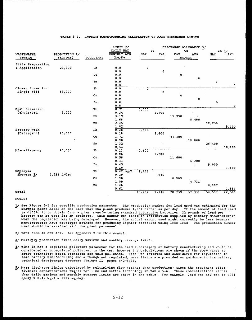
TABLE 5-4. BATTERY MANUFACTURING CALCULATION OF MASS DISCHARGE LIMITS
LIMIT 2/ DISCHARGE ALLOWANCE .Y DAILY MAX Pb Cu Zn .Y
WASTEWATER PRODUCTION y MONTHLY AVG MAX AVG MAX AVG MAX AVG STREAM (KG/DAY) POLLUTANT (MG/KG) (MG/DAY)
Paste Preparation ft Application 20,000 Pb o.o 0
o.o 0 cu o.o 0
o.o 0 Zn o.o 0
o.o 0 Closed Formation Pb 0.0 0 single Fill 15,000 o.o 0
Cu o.o 0 0.0 0
Zn o.o 0 o.o 0
Open Formation Pb 0. 71 3,550 Dehydrated 5,000 0.34 1,700
cu 3.19 15,950 1. 68 8,400
Zn 2.45 12,250 1.02 5,100
Battery Wash Pb 0.38 7,600 (Detergent) 20,000 0.18 3,600
cu 1. 71 34,200 0.90 18,000
Zn 1. 32 26,400 0.54 10,800
Miscellaneous 20,000 Pb 0.13 2,600 0.06 1,200
cu 0.58 11,600 0.31 6,200
Zn 0.45 9,000 0.19 3,800
Employee Pb 0.42 mg/l 1,987 Showers y 4,731 L/day 0.20 946
cu 1.90 8,989 1.00 4,731
Zn 1. 46 6,907 0.61 2,886
Total 15,737 7,446 70,739 37 ,·331 54,557 22,586
NOTES:
y See Figure 5-l·for specific: production parameter. The production number for lead used was estimated for the example plant based on the fact that the plant produces 1,364 batteries per day. If the amount of lead used is difficult to obtain from a plant manufacturing standard automotive batteries, 22 pounds of lead per battery can be used for an estimate. This number was based on information supplied by battery manufacturers when the regulation was being developed. However, the actual amount used might currently be less because manufacturers have developed methods for producing lighter batteries using less lead. The production number used should be verified with the plant personnel.
~/ PSES from 40 CFR 461. See Appendix B in this manual.
!I Multiply production times daily maximum and monthly average limit.
4/ Zinc: is not a regulated pollutant parameter for the lead subcategory of battery manufacturing and would be - considered an unregulated pollutant in the CWF, however the calculations are shown if the POTW wants to
apply technology-based standards for this pollutant. Zinc was detected and considered for regulation in lead battery manufacturing and although not regulated, mass limits are provided as guidance in the battery technical development document (Volume II, pages 642-649).
Mass discharge limits calculated by multiplying flow (rather than production) times the treatment effectiveness concentrations '(mg/ll for lime and settle technology in Table 5-6. These concentrations rather than daily maximum and monthly average limits are shown in the table. For example, lead one day max is 4731 l/day X 0.42 mg/l = 1987 mg/day.
5-12

each process operation and a treatment effectiveness concen
tration table for all pollutants of concern based on treatment
systems used for BAT and NSPS for direct dischargers. The
example in Table 5-5 illustrates how to calculate the mass dis
charge limits for lead, copper and zinc for the secondary lead
smelter operations at the example plant. Table 5-5 also presents
the production normalized flows needed to calculate mass limits
for the secondary lead smelter operations, and Table 5-6 presents
the treatment effectiveness concentrations used for the nonfer
rous metals manufacturing regulation.
5-13
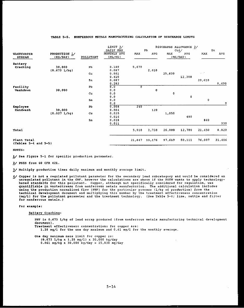
WASTEWATER STREAM
Battery crackin9
TABLE 5-5. NONFERROUS METALS MANUFACTURING CALCULATION OF DISCHl\RGE LIMITS
PRODUCTION .!/ (KG/DAY)
30,000 (0.673 1/kg)
POLLUTANT
Pb
cu
Zn
LIMIT 2/ DAILY MAX
MONTHLY AVG (MG/KG)
0.189 0.087 0.861 0.410 0.687
MAX
5,670
Pb DISCHARGE ALLOWANCE ~/
cuy AVG MAX AVG
(MG/DAY)
2,610 25,830
12,300
Zn MAX AVG
20,610 0.283 8,490
Facility Wash down
Employee Handwash
30,000
30,000 (0.027 l/kg)
Pb o.o 0.0
Cu 0.0 0.0
Zn 0.0 0.0
Pb 0.008 0.004
cu 0.035 0.016
Zn 0.028
0 0
0 0
0 0
240 120
1,050 480
840 0. 011 330
Total 5,910 2,730 26,880 12,780 21,450 8,820
Plant Total 21,647 10,176 97,619 50,111 76,007 31,406 (Tables 5-4 and 5-5)
NOTES:
!I Seo Figure 5-1 for specific production parameter.
~I PSES from 40 CFR 421.
11 Multiply production times daily maximum and monthly average limit.
.Y Copper is not a regulated pollutant parameter for the secondary lead subcategory and would be considered an unregulated pollutant in the CWF, however the calculations are shown if the POTW wants to apply technologybased standards for this pollutant. Copper, although not specifically considered for regulation, was quantifiable in wastestreams from nonferrous metals manufacturing. The additional calculation includes using the production normalized flow (PNF) for the particular process (l/kg of production) from the technical development document and multiplying this number by the treatment effectiveness concentration (mg/ll for the pollutant parameter and the treatment technology. (See Table 5-6; lime, settle and filter for nonferrous metals.)
For example:
Battery Cracking:
PNF is 0.673 l/kg of lead scrap produced (from nonferrous metals manufacturing technical development document). Treatment effectiveness concentrations for copper are:
1.28 mg/l for the one day maximum and 0.61 mg/1 for the monthly average.
one day maximum mass limit for copper is: (0.673 l/kg x 1.28 mg/l) x 30,000 kg/day 0.861 mg/kg x 30,000 kg/day = 25,830 mg/day
5-14
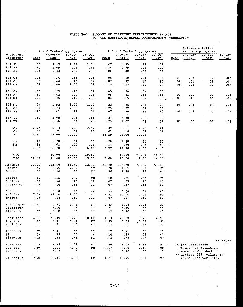
Pollutant Parameter
114 Sb 115 As 117 Be
118 Cd 119 Cr 120 cu
121 en 122 Pb 123 Hg
124 Ni 125 Se 126 Ag
127 Tl 128 Zn
Al Co F
Fe Mn p
O&G TSS
Ammonia Barium Boron
Cesium Gallium Germanium
Gold Hafnium Indium
Molybdenum Palladium Platinum
Radium*** Rhenium Rubidium
Tantalum Tin Titanium
Tungsten Uranium Vanadium
Zirconium
TABLE 5-6. SUMMJ\RY OF TREATMENT EFFECTIVENESS (mg/I) FOR THE NONFERROUS, METALS MANUFACTURING REGULATION
L & S Technology System one-Day 10-Day 30-Day
Mean Max ~ ~
.70
.51
. 30
.08
.08
. 58
.07
.12
.06
.74
. 30
.10
.50
.33
2.24 .05
14.50
.41
.16 4. 08
12.00
32.20 .42 .36
.12
.08
.08
** 7.28
.08
1. 83 ** **
6.17 1. 83
.12
** .14 .19
1. 29 4.00
**
7.28
2.87 2.09 1. 23
.34
.44 1. 90
.29
.42
. 25
1. 92 1. 23
.41
2.05 1. 46
6.43 .21
35.00
1. 20 .68
16.70
20.00 41. 00
133.30 5.55 1. 84
.51
.44
.44
*.10 28.80
.44
6.61 *.10 *.10
30.00 6.61
.51
*.45 .38 .94
6.96 6.50 *.10
28.80
1. 28 .93 .55
.15
.18 1. 00
.12
.20
.10
1. 27 '. 55
.17
.91
.61
3.20 .09
19.90
.61
.29 6.83
12.00 19.50
58. 60. 2.54
.84
.23
.18
.18
** 13.90
.18
3.42 ** **
11. 23 3.42
.23
** .22 .41
2.78 4.73
**
13.90
1.14 .83 .49
.13
.12
.73
.11
.16
.10
1.00 .49 .16
.81
.45
2.52 .08
.50
.21 6.60
10.00 15.50
52.10 NC NC
NC .12 .12
** NC
.12
NC ** **
10.00 NC NC
** ** NC
NC NC **
NC
L s & F Te.chnology system One-Day 10-Day 30-Day
Mean Max, ~ ~
.47
.34
.20
.05
.07
.39
.05
.08
.04
.22
.20
.07
. 34
.23
1.49 .03
14.50
.28
.14 2.72
2.60
32.20 .28 .36
.12
.07
.07
** 4.81
.07
1. 23 ** **
4.13 1. 23
.12
** .14 .13
.85 2.67
**
4.81
1. 9'3 1. 39 .8~
.20
.37 1. 28
.20
.28
.15
.55
.82
.29
1.40 1. 02
6 .11 .14
35.00
1. 20 .30
11.20
10.00 15.00
133.30 1.15 1. 84
.51
. 37
. 3,7
•. 10 19.70
.37
5. 0:3 *.10 *.10
20.00 5.03
.51
3. 4'8 4.29 •. 1,0
19.70
5-15
.86
.62
.37
.08
.15
.61
.08
.13
.06
. 37
.37
.12
.61
.42
2. 71 .07
19.90
.61
.23 4.60
10.00 12.00
58.60 .51 .84
.23
.15
.15
** 9.01
.15
2.23 ** **
7.25 2.23
.23
** . 22 .23
1. 55 3.12
**
9.01
.76
.55
.32
.08
.10
.49
.08
.11
.06
.29 • 33 .10
.55
. 31
2.41 .06
.50
.19 4.40
10.00 10.00
52.10 NC NC
NC .10 .10
** NC
.10
NC •• **
6.67 NC NC
** ** NC
NC NC **
NC
Sulfide & Filter Technology System One-Day 10-Day
Mean Max ~ 30-Day
~
.01
.08
.05
.01
.03
.05
.05
.01
.04
.21
.21
.04
.13
.21
.21
.04
.02
.09
.09
.02
.06
.09
.09
.02
.02
.08
.08
.02
.05
.08
.08
.02
07/03/86 NC Not Calculated
*Limits of Detection **None Established
***Isotope 226, Values in picocuries per liter

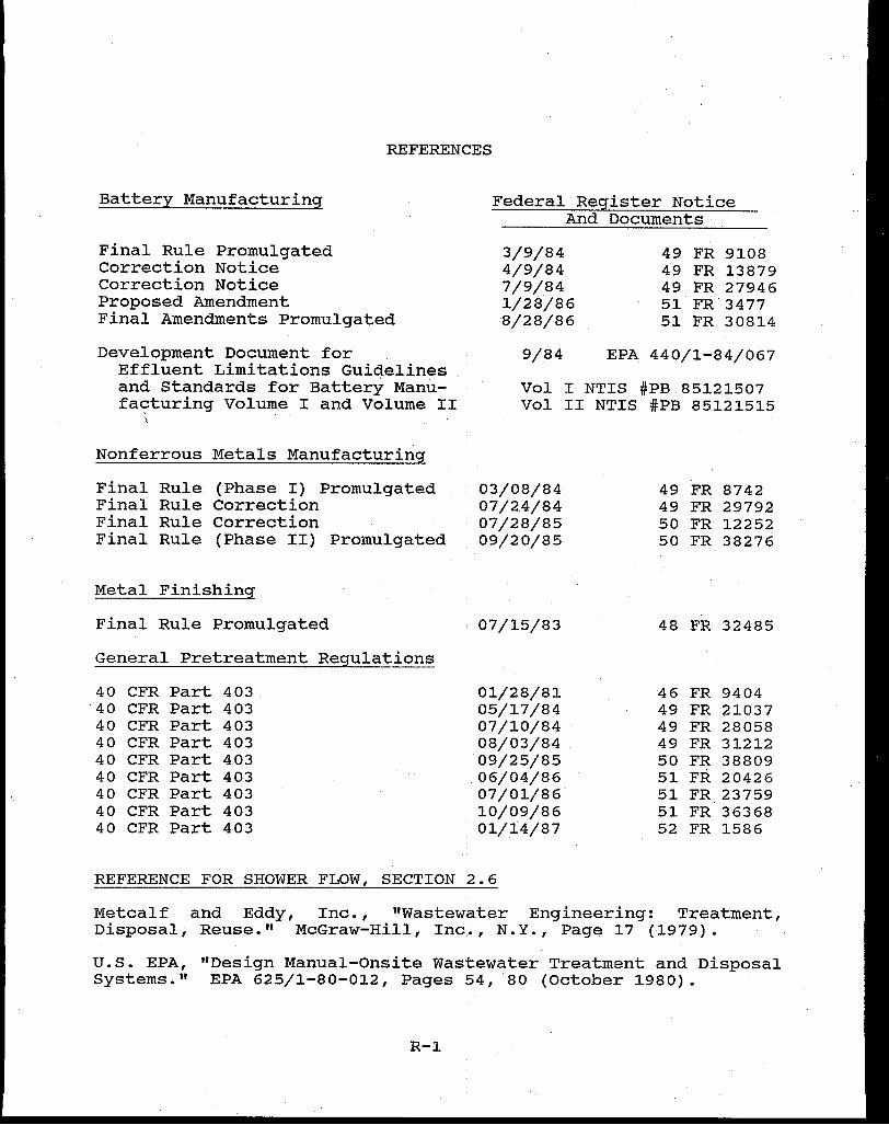
REFERENCES
Battery Manufacturing
Final Rule Promulgated Correction Notice Correction Notice Proposed Amendment Final Amendments Promulgated
Development Document for Effluent Limitations Guidelines and Standards for Battery Manufa~turing Volume I and Volume II
"
Nonferrous Metals Manufacturing
Final Rule (Phase I) Promulgated Final Rule Correction Final Rule Correction Final Rule (Phase II) Promulgated
Metal Finishing
Final Rule Promulgated
General Pretreatment Regulations
40 CFR Part 403 '40 CFR Part 403 40 CFR Part 403 40 CFR Part 403 40 CFR Part 403 40 CFR Part 403 40 CFR Part 403 40 CFR Part 403 40 CFR Part 403
REFERENCE FOR SHOWER FLOW, SECTION
Federal Register Notice And Documents
3/9/84 49 FR 9108 4/9/84 49 FR 13879 7/9/84 49 FR 27946 1/28/86 51 FR 3477 8/28/86 51 FR 30814
9/84 EPA 440/1-84/067
Vol I NTIS #PB 85121507 Vol II NTIS #PB 85121515
03/08/84 49 FR 8742 07/24/84 49 FR 29792 07/28/85 50 FR 12252 09/20/85 50 FR 38276
07/15/83 48 FR 32485
01/28/81 46 FR 9404 05/17/84 49 FR 21037 07/10/84 49 FR 28058 08/03/84 49 FR 31212 09/25/85 50 FR 38809 06/04/86 51 FR 20426 07/01/86 51 FR 23759 10/09/86 51 FR 36368 01/14/87 52 FR 1586
'2. 6
Metcalf and Eddy, Inc., "Wastewater Engineering: Treatment, Disposal, Reuse." McGraw-Hill, Inc,. , N. Y. , Page 17 ( 1979) .
U.S. EPA, "Design Manual-Onsite Wastewater Treatment and Disposal Systems." EPA 625/1-80-012, Pages 54, 80 (October 1980).
R-1
REFERENCES (continued)
GUIDANCE MANUALS
Guidance Manual for POTW Pretreatment Program Development
Procedures Manual for Reviewing a POTW Pretreatment Pretreatment Program
Guidance Manual for the Use of Production-Based Pretreatment Standards and the Combined Wastestream Formula
Pretreatment Implementation Review Task Force (PIRT) Final Report
Guidance Manual for Implementing Total Toxic Organics (TTO) Pretreatment Standards
RCRA Information on Hazardous Wastes for Publicly owned Treatment Works
Guidance Manual Preparing and Reviewing Removal Credits Applications
Compliance Monitoring and Enforcement Guidance
PRELIM 3.0: EPA Computer Model for Development of Local Limits (user manual and computer disk for use on an IBM compatible microcomputer)
Guidance Manual for Electroplating and Metal Finishing Pretreatment Standards
October 1983
October 1983
September 1985
January 1985
September 1985
September 1985
September 1985
July 1986
September 1986
February 1984
Copies of the technical and economic documents may be obtained from the USEPA, Industrial Technology Division (WH-552), Washington, DC, (202) 382-7126, or from the National Technical Information Services (NTIS), Springfield, VA 22161, (703) 487-4650. Pretreatment Program Manuals may be obtained from USEPA, Permits Division (EN-336), Washington, D.C. 20460, 202-475-9526.
R-2
APPENDIX A
GLOSSARY OF TERMS

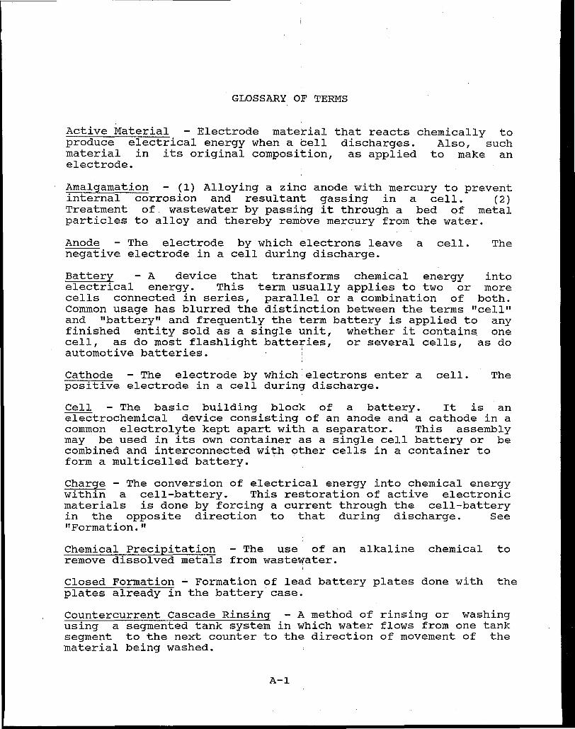
GLOSSARY OF TERMS
Active Material - Electrode material that reacts chemically to produce electrical energy when a cell discharges. Also, such material in its original composition, as applied to make an electrode.
Amalgamation - (1) Alloying a zinc anode with mercury to prevent internal corrosion and resultant gassing in a cell. (2) Treatment of wastewater by passing it through a bed of metal particles to alloy and thereby remove mercury from the water.
Anode - The electrode by which electrons leave a cell. The negative electrode in a cell during discharge.
Battery - A device that transforms chemical energy into electrical energy. This term usually applies to two or more cells connected in series, parallel or a combination of both. Common usage has blurred the distinction between the terms "cell" and "battery" and frequently the term battery is applied to any finished entity sold as a single unit, whether it contains one cell, as do most flashlight batteries, or several cells, as do automotive batteries. '
Cathode - The electrode by which electrons enter a cell. The positive electrode in a cell during discharge.
Cell - The basic building block of a battery. It is an electrochemical device consisting of an anode and a cathode in a common electrolyte kept apart with a separator. This assembly may be used in its own container as a single cell battery or be combined and interconnected with other cells in a container to form a multicelled battery.
Charge - The conversion of electrical energy into chemical energy within a cell-battery. This restoration of active electronic materials is done by forcing a current through the cell-battery in the opposite direction to that during discharge. See "Formation."
Chemical Precipitation - The use of an alkaline chemical to remove dissolved metals from wastewater.
Closed Formation ~ Formation of lead battery plates done with the plates already in the battery case.
Countercurrent cascade Rinsing - A method of rinsing or washing using a segmented tank system in which water flows from one tank segment to the next counter to the direction of movement of the material being washed.
A-1

Current Collector - The grid portion of the electrode which conducts the current to the terminal.
Depolarizer - A term often used to denote the cathode active material.
Dry Charge Process - A process for the manufacture of lead acid storage batteries in which the plates are charged by electrolysis in sulfuric acid, rinsed, and drained or dried prior to shipment of the battery. Charging of the plates usually occurs in separate containers before assembly of the battery but may be accomplished in the battery case. Batteries produced by the drycharge process are shipped without acid electrolyte. Also referred to as dehydrated plate or dehydrated batteries.
Electrode - The positive (cathode) or negative (anode) element in a cell or battery, that enables it to provide electric power.
Electrodeposition - Electrochemical deposition of an active material from solution onto an electrode grid or plague.
Electroforming - See (1) Electrodeposition, and (2) Formation.
Electrolyte - The liquid or material that permits conduction of ions between cell electrodes.
Electrolytic Precipitation - Generally refers to making powdered active material by electrodeposition and physical removal; e.g., silver powder from silver bars.
Electroplating - (1) Electrodeposition of a metal or alloy from a suitable electrolyte solution; the article to be plated is connected as the cathode in the electrolyte solution; direct current is introducted though the anode which consists of the metal to be deposited. (2) The Electroplating Point Source Category.
Element - A combination of negative and positive plates and separators to make a cell in a lead-acid storage battery.
End-of-Pipe Treatment - The reduction or removal of pollutants by treatment just prior to actual discharge to a point outside an industrial plant.
Filtration - Removal of solid particles from liquid or particles from air or gas stream through a permeable membrane or deep bed. The filter types include: gravity, pressure, microstraining, ultrafiltation, reverse osmosis (hyperfiltration).
A-2
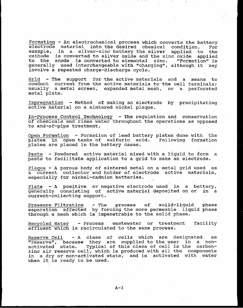
Formation - An electrochemical process which converts the battery electrode material into the desired chemical condition. For example, in a· silver-zinc battery the silver applied to the cathode is converted to silver oxide and the zinc oxide applied to the anode is converted to elemental zinc. "Formation" is
·generally used interchangeable wi'th "charging", although it may involve a repeated charge-discharge cycle.
Grid - The support for the active materials and a means to conduct current from the active materials to the cell terminals; usually a metal screen, expanded metal mesh, or a perforated metal plate.
Impregnation - Method of making an electrode by precipitating active material on a sintered nickel plaque.
In-Process Control Technology - The regulation and conservation of chemicals and rinse water throughout the operations as opposed to end-of-pipe treatment.
Open Formation - Formation of lead battery plates done with the plates in open tanks of sulfuric acid. Following formation plates are placed in the battery cases.
Paste - Powdered active material mixed with a liquid to form a paste to facilitate application to a grid to make an electrode.
Plague - A porous body of sintered metal on a metal grid used as a current collector and holder of electrode active materials, especially for nickel-cadmium batteries.
Plate - A positive or negative electrode used in a bettery, generally consisting of active material deposited on or in a current-collecting support.
Pressure Filtration - The process of solid-liquid phase separation effected by forcing the more permeable liquid phase through a mesh which is impenetrable to the solid phase.
Recycled Water - Process wastewater or treatment effluent which is recirculated to the same process.
facility
Reserve Cell - A class of cells which are designated as "reserve", because they are supplied to the user in a nonactivated state. Typical of this class of cell is the carbonzinc air reserve cell, which is produced with all the components in a dry or non-activated state, · and is activated with water when it is ready to be used.
A-3
Reused Water - Process wastewater or treatment facility effluent which is further used in a different manufacturing process. For example, the reuse of process wash water as noncontact cooling water.
Sedimentation - The gravity induced deposition of suspended matter carried by water, wastewater, or other liquids, by gravity. It is usually accomplished by reducing the velocity of the suspended material. Also called settling.
Separator - A porous material, in a battery system, used to keep plates of opposite polarity separated, yet allowing conduction of ions through the electrolyte.
Sinter - Heating a metal powder such as nickel to an elevated temperature below its melting point which causes it to agglomerate and adhere to the supporting grid.
Sintered-plate Electrode - The electrode formed by sintering metallic powders to form a porous structure, which serves as a current collector, and on which the active electrode material is deposited.
Storage Battery - A battery that can store chemical energy with the potential to change to electricity. This conversion of chemical energy to electricity can be reversed thus allowing the battery to be recharged.
Wet Charge Process - A process for the manufacture ·of lead acid storage batteries in which the plates are formed by electrolysis in sulfuric acid. The plate forming process is usually done with the plates inside the assembled battery case but may be done with the plates in open tanks. In the case of large industrial wet lead acid batteries, problems in formation associated with inhomogeneities in the large plates are alleviated by open tank formation. Wet charge process batteries are shipped with acid electrolyte inside the battery casing.
Wet Scrubber - A unit in which dust and fumes are removed from an air or gas stream to a liquid. Gas-liquid contact is promoted by jets, sprays, bubble chambers, etc.
A-4
APPENDIX B
PSES AND PSNS FOR BAT~ERY MANUFACTURING SUBCATEGORIES

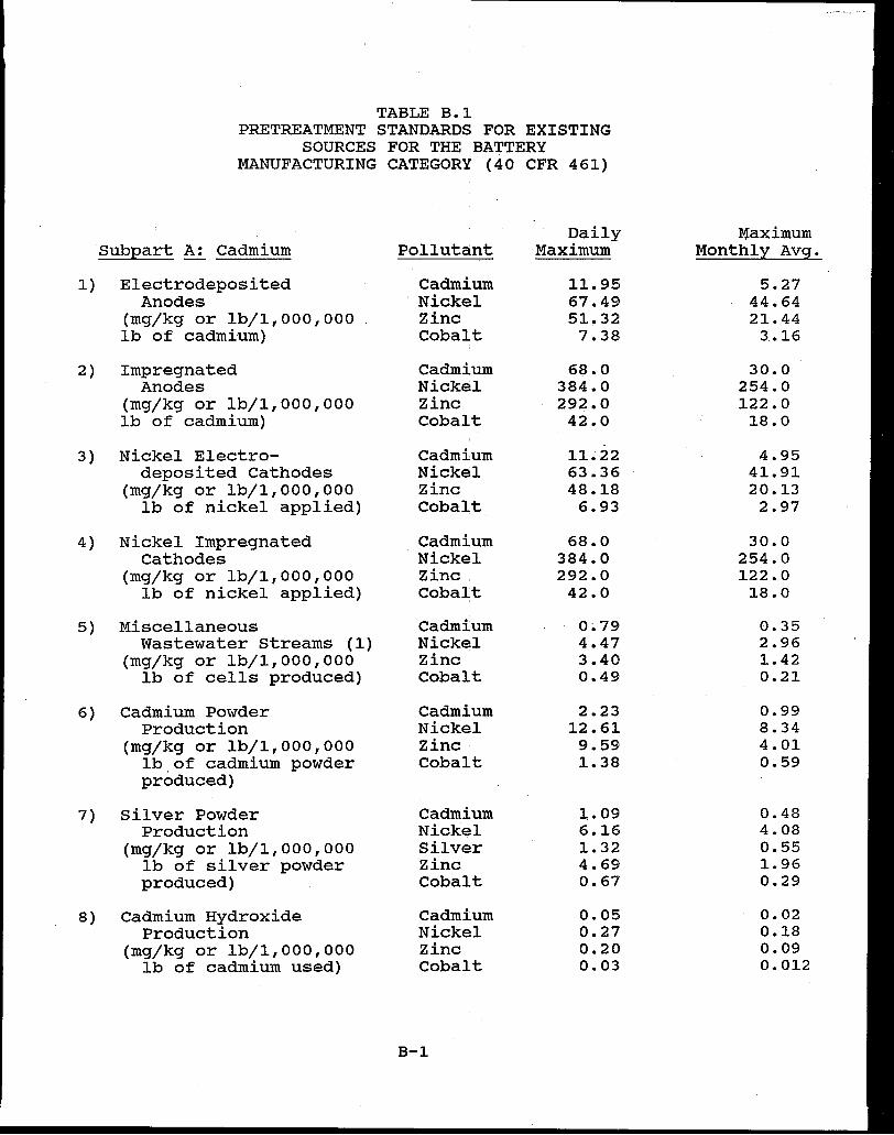
1)
2)
3)
4)
5)
6)
7)
8)
TABLE B.1 PRETREATMENT STANDARDS FOR EXISTING
SOURCES FOR THE BATTERY MANUFACTURING CATEGORY (40 CFR 461)
Daily Subpart A: Cadmium Pollutant Maximum
Electrodeposited Cadmium 11.95 Anodes ·Nickel 67.49
(mg/kg or lb/1,000,000 Zinc 51.32 lb of cadmium) Cobalt 7.38
Impregnated Cadmium 68.0 Anodes Nickel 384.0
(mg/kg or lb/1,000,000 Zinc 292.0 lb of cadmium) Cobalt 42.0
Nickel Electro- Cadmium 11.22 deposited Cathodes Nickel 63.36
(mg/kg or lb/1,000,000 Zinc 48.18 lb of nickel applied) Cobalt 6.93
Nickel Impregnated Cadmium 68.0 cathodes Nickel 384.0
(mg/kg or lb/1,000,000 Zinc. 292.0 lb of nickel applied) Cobalt 42.0
Miscellaneous Cadmium 0~79
Wastewater Streams (1) Nickel 4.47 (mg/kg or lb/1,000,000 Zinc 3.40
lb of cells produced) Cobalt 0.49
Cadmium Powder Cadmium 2.23 Production Nickel 12.61
(mg/kg or lb/1,000,000 Zinc· 9.59 lb of cadmium powder Cobalt 1.38 produced)
Silver Powder Cadmium 1.09 Production Nickel 6.16
(mg/kg or lb/1,000,000 Silver 1.32 lb of silver powder Zinc 4.69 produced) Cobalt 0.67
Cadmium Hydroxide Cadmium 0.05 Production Nickel 0.27
(mg/kg or lb/1,000,000 Zinc 0.20 lb of cadmium used) Cobalt 0.03
B-1
Maximum Monthly Avg.
5.27 44.64 21.44
3 .• 16
30.0 254.0 122.0 18.0
4.95 41.91 20.13
2.97
30.0 254.0 122.0
18.0
0.35 2.96 1.42 0.21
0.99 8.34 4.01 0.59
0.48 4.08 0.55 1.96 0.29
0.02 0.18 0.09 0.012

TABLE B.1 PRETREATMENT STANDARDS FOR EXISTING
SOURCES FOR THE BATTERY MANUFACTURING CATEGORY (40 CFR 461) (continued)
Subpart A: Cadmium (cont'd)
9) Nickel Hydroxide Production
(mg/kg or lb/1,000,000 lb of nickel used)
Subpart c: Lead
Pollutant
Cadmium Nickel Zinc Cobalt
1) Open Formation- Copper Dehydrated Lead
(mg/kg or lb/1,000,000 lb of lead used)
2) Open Formation-Wet Copper (mg/kg or lb/1,000,000 Lead
lb of lead used)
3) Plate Soak Copper (mg/kg or lb/1,000,000 Lead
lb of lead used)
4) Battery Wash-Detergent (2) Copper (mg/kg or lb/1,000,000 Lead
lb of lead used)
5) Direct Chill Lead Casting Copper (mg/kg or lb/1,000,000 Lead
lb of lead used)
6) Mold Release Formulation Copper (mg/kg or lb/1,000,000 Lead
lb of lead used)
7) Truck Wash Copper (mg/kg or lb/1,000,000 Lead
lb of lead in trucked batteries)
8) Laundry Copper (mg/kg or lb/1,000,000 Lead
lb of lead used)
B-2
Daily Maximum
5.61 31. 68 24.09 3.47
3.19 0.71
0.100 0.022
0.039 0.008
1.71 0.38
0.0004 0.00008
0.011 0.002
0.026 0.005
0.21 0.05
Maximum Monthly Avg
2.48 20.96 10.07 1.49
1. 68 0.34
0.053 0.010
0.021 0.004
0.90 0.18
0.0002 0.00004
0.006 0.001
0.014 0.002
0.11 0.02

TABLE B.1 PRETREATMENT STANDARDS FOR EXISTING
SOURCES FOR THE BATTERY MANUFACTURING CATEGORY (40 CFR 461) (continued)
Daily Maximum Subpart.C: Lead (cont'd) Pollutant Maximum Monthly Avg
9) Miscellaneous Copper 0.58 0.31 Wastewater Streams (3) Lead 0.13 0.06
(mg/kg or lb/1,000,000 lb of lead used)
Subpart D: Leclanche
1) Foliar Battery Mercury 0.010 0.004 Misc. Wash Zinc 0.067 0.030
(mg/kg or lb/1,000,000 Manganese 0.019 0.015 lb of cells produced)
.Subpart F: Magnesium
1) Silver Chloride Cathodes- Lead 1,032.36 491. 60 Chemically Reduced Silver 1,007.78 417.86
(mg/kg or lb/1,000,000 lb of silver processed)
2) Silver Chloride Cathodes- Lead. •60.9 29.0 Electrolytic Silver 59.5 24.7
(mg/kg or lb/1,000,000 lb of silver processed)
3) Cell Testing Lead. 22.1 10.5 (mg/kg or lb/1,000,000 Silver 21.6 8.9
lb of cells produced)
4) Floor and Equipment Wash Lead 0.039 0.018 (mg/kg or lb/1,000,000 Silv~r 0.038 0.015
lb of cells produced)
Sub:eart G: Zinc
1) Wet Amalgamated Chromium 0.24 0.099 Powder Anode Mercury 0.14 0.055
(mg/kg or lb/1,000,000 Silver 0.23 . 0. 093 lb of zinc) Zinc, o. 80 0.34
Manganese 0.37 0.16
B-3

TABLE B.1 PRETREATMENT STANDARDS FOR EXISTING
SOURCES FOR THE BATTERY MANUFACTURING CATEGORY (40 CFR 461) (continued)
Maximum Subpart G: Zinc (cont'd)
2) Gelled Amalgam Anodes
Pollutant Daily
Maximum Monthly Avg
(mg/kg or lb/1,000,000 lb of zinc)
3) Zinc oxide Formed Anodes (mg/kg or lb/1,000,000
lb of zinc)
4) Electrodeposited Anodes (mg/kg or lb/1,000,000
lb of zinc deposited)
5) Silver Powder Formed Cathodes
(mg/kg or lb/1,000,000 lb of silver applied)
6} Silver Oxide Powder Formed Cathodes
(mg/kg or lb/1,000,000 lb of silver applied)
7) Silver Peroxide cathodes
(mg/kg or lb/1,000,000 lb of silver applied)
8) Nickel Impregnated Cathodes
(mg/kg or lb/1,000,000 lb of nickel applied)
Chromium Mercury Silver Zinc Manganese
Chromium Mercury Silver Zinc Manganese
Chromium Mercury Silver Zinc Manganese
Chromium Mercury Silver Zinc Manganese
Chromium Mercury Silver Zinc Manganese
Chromium Mercury Silver Zinc Manganese
Chromium Mercury Nickel Silver Zinc Manganese
B-4
0.030 0.017 0.028 0.099 0.046
9.53 5.42 8.89
31. 64 14.74
94.47 53.68 86.03
313.46 146.00
13.07 7.43
12.18 43.36 20.20
8.73 4.96 8.14
28.98 13.50
2.09 1.19 1. 95 6.95 3.24
88.0 50.0
384.0 82.0
292.0 136.0
0.012 0.006 0.012 0.042 0.020
3.90 2.17 3.68
13.22 6.28
38.65 21.47 36.50
130.97 62.26
5.35 2.97 5.05
18.12 8.61
3.57 1.99 3.37
12.11 5.76
0.87 0.48 0.81 2.90 1. 38
36.0 20.0
254.0 34.0
122.0 58.0

TABLE B.1 PRETREATMENT STANDARDS FOR EXISTING
SOURCES FOR THE BATTERY MANUFACTURING CATEGORY (40 CFR 461) (continued)
Subpart G: Zinc (cont'd) Pollutant Daily
Maximum Maximum
Monthly Avg
9) Miscellaneous Wastewater Streams (4)
(mg/kg or lb/1,000,000 lb of cells produced)
·Chromium Cyanide Mercury Nickel Silver Zinc Mang~nese
0.57 0.38 0.32 2.48 0.53 1.88 0.88
0.23 0.16 0.13 1.64 0.22 0.79 0.37
10) Silver Etch Chromium Mercury Silver Zinc Manganese
3.27 1.86 3.05
1.34 0.74 1.26 4.54 2~16
(mg/kg or lb/1,000,000 lb of silver proc~ssed)
10.86 5.06
11) Silver Peroxide Production
Chromium Mercury Silver Zinc Manganese
3.48 1.96 3.24
1.42 0.79 1.34 4.83 2.29
(mg/kg or lb/1,000,000 lb of silver in silver peroxide produced)
11.55 5.38
12) Silver Powder Chromium Mercury Silver Zinc Manganese
1.41 0.80 1.32 4.69 2.18
0.58 0.32 0.55 1.96 0.93
(1)
(2)
(3)
(4)
Production (mg/kg or lb/1,000,000
lb of silver powder produced)
Includes discharges from cell wash, electrolyte preparation, floor and equipment wash, and employee wash.
Numbers reflect amendment as a result of a settlement agreement between EPA and lead battery manufacturers.
Includes discharges from floor ~ash, wet air pollution control, battery repair, laboratory, hand wash, and respirator wash.
Includes discharges from cell wash, electrolyte preparation, employee wash, reject cell handling, and floor and equipment wash.
·B-5
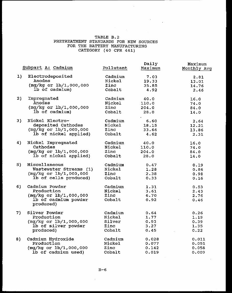
TABLE B.2 PRETREATMENT STANDARDS FOR NEW SOURCES
FOR THE BATTERY MANUFACTURING CATEGORY (40 CFR 461)
Daily Maximum Subpart A: Cadmium Pollutant Maximum Monthly Avg
l) Electrodeposited Cadmium 7.03 2.81 Anodes Nickel 19.33 13.01
(mg/kg or lb/1,000,000 Zinc 35.85 14.76 lb of cadmium) Cobalt 4.92 2.46
2) Impregnated Cadmium 40.0 16.0 Anodes Nickel 110.0 74.0
(mg/kg or lb/1,000,000 Zinc 204.0 84.0 lb of cadmium) Cobalt 28.0 14.0
3) Nickel Electro- Cadmium 6.60 2.64 deposited Cathodes Nickel 18.15 12.21
(mg/kg or lb/1,000,000 Zinc 33.66 13.86 lb of nickel applied) Cobalt 4.62 2.31
4) Nickel Impregnated Cadmium 40.0 16.0 Cathodes Nickel 110.0 74.0
(mg/kg or lb/1,000,000 Zinc 204.0 84.0 lb of nickel applied) Cobalt 28.0 14.0
5) Miscellaneous Cadmium 0.47 0.19 Wastewater Streams (1) Nickel 1.28 0.86
(mg/kg or lb/1,000,000 Zinc 2.38 0.98 lb of cells produced) Cobalt 0.33 0.16
6) Cadmium Powder Cadmium 1. 31 0.53 Production Nickel 3.61 2.43
(mg/kg or lb/1,000,000 Zinc 6.70 2.76 lb of cadmium powder Cobalt 0.92 0.46 produced)
7) Silver Powder Cadmium 0.64 0.26 Production Nickel 1.77 1.19
(mg/kg or lb/1,000,000 Silver 0.93 0.39 lb of silver powder Zinc 3.27 1.35 produced) Cobalt 0.45 0.22
8) Cadmium Hydroxide Cadmium 0.028 0.011 Production Nickel 0.077 0.051
(mg/kg or lb/1,000,000 Zinc 0.142 0.058 lb of cadmium used) Cobalt 0.019 0.009
B-6
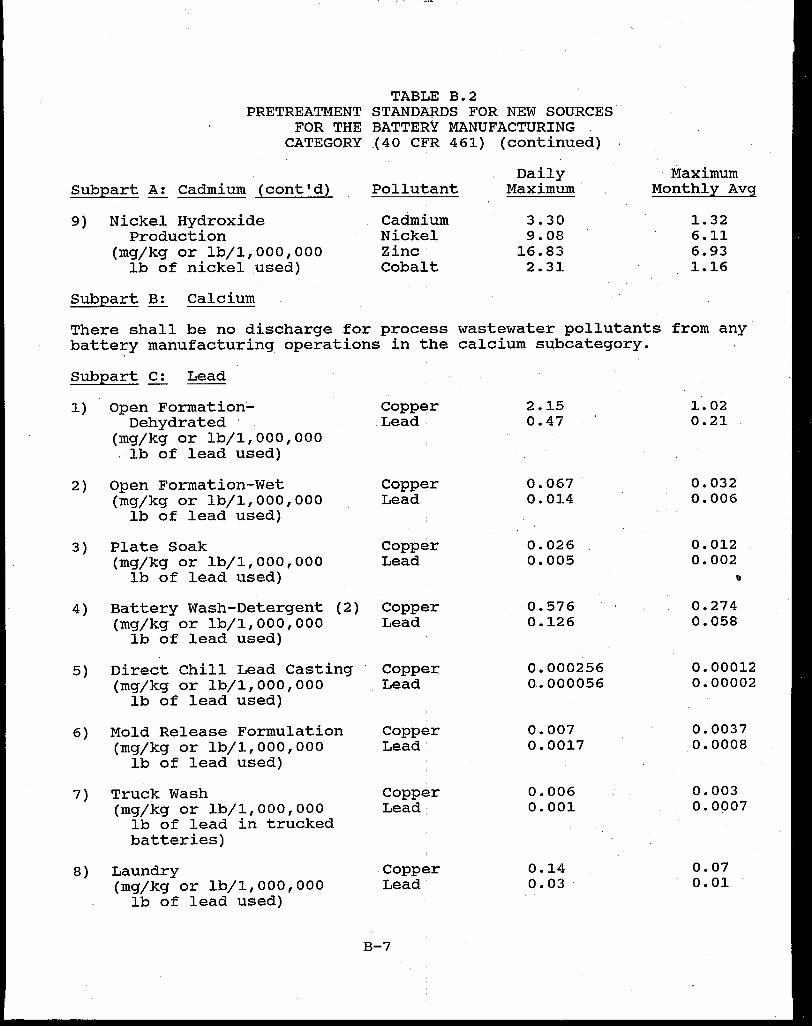
TABLE B.2 PRETREATMENT STANDARDS FOR NEW SOURCES
FOR THE BATTERY MANUFACTURING CATEGORY .(40 CFR 461) (continued)
Subpart A: Cadmium (cont'd)
9) Nickel Hydroxide Production
(mg/kg or lb/1,000,000 lb of nickel used)
Subpart B: Calcium
Pollutant
Cadmium Nickel Zinc· Cobalt
Daily Maximum·
3.30 9.08
16.83 2.31
Maximum Monthly Avg
1.32 6.11 6.93 1.16
There shall be no discharge for process wastewater pollutants from any battery manufacturing operations in the calcium subcategory.
Subpart C: Lead
1) Open FormationDehydrated
(mg/kg or lb/1,000,000 lb of lead used)
2) Open Formation-Wet (mg/kg or lb/l,000,000
lb of lead used)
3) Plate Soak (mg/kg or lb/1,000,000
lb of lead used)
4) Battery Wash-Detergent (2) (mg/kg or lb/1,000,000
lb of lead used)
5) Direct Chill Lead Casting (mg/kg or lb/1,000,000
lb of lead used)
6) Mold Release Formulation (mg/kg or lb/1,000,000
lb of lead used)
7) Truck Wash (mg/kg or lb/1,000,000
lb of lead in trucked batteries)
8) Laundry (mg/kg or lb/1,000,000
lb of lead used)
Copper Lead
Copper Lead
copper Lead
copper Lead
Copper Lead
Copper Lead'
Copper Lead
Copper Lead
B-7
2.15 0.47
0.067 0.014
0.026 0.005
0.576 0.126
0.000256 0 .• 000056
0.007 0.0017
0.006 0.001
0.14 0.03
1. 02 0.21
0.032 0.006
0.012 0.002
e
0.274 0.058
0.00012 0.00002
0.0037 0.0008
0.003 0.0007
0.07 0.01
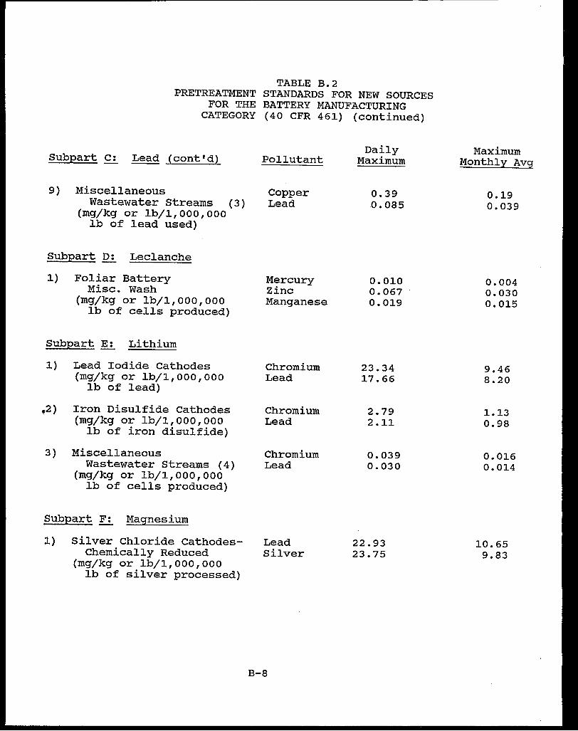
TABLE B.2 PRETREATMENT STANDARDS FOR NEW SOURCES
FOR THE BATTERY MANUFACTURING CATEGORY (40 CFR 461) (continued)
Subpart c: Lead (cont'd)
9) Miscellaneous Wastewater streams
(mg/kg or lb/1,000,000 (3)
lb of lead used)
Subpart D: Leclanche
1) Foliar Battery Misc. Wash
(mg/kg or lb/1,000,000 lb of cells produced)
Subpart E: Lithium
1) Lead Iodide Cathodes (mg/kg or lb/1,000,000
lb of lead)
,2) Iron Disulfide Cathodes (mg/kg or lb/1,000,000
lb of iron disulfide)
3) Miscellaneous Wastewater Streams (4)
(mg/kg or lb/1,000,000 lb of cells produced)
Subpart F: Magnesium
l) Silver Chloride CathodesChemically Reduced
(mg/kg or lb/1,000,000 lb of silver processed)
Pollutant
Copper Lead
Mercury Zinc Manganese
Chromium Lead
Chromium Lead
Chromium Lead
Lead Silver
B-8
Daily Maximum
0.39 0.085
0.010 0.067 0.019
23.34 17.66
2.79 2.11
0.039 0.030
22.93 23.75
Maximum Monthly Avg
0.19 0.039
0.004 0.030 0.015
9.46 8.20
1.13 0.98
0.016 0.014
10.65 9.83
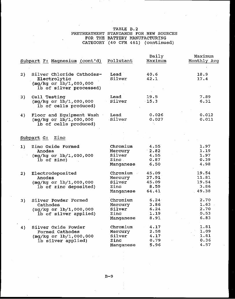
TABLE B.2 PRETREATMENT STANDARDS FOR NEW SOURCES
FOR THE B.ATTERY MANUFACTURING CATEGORY ( 40 CFR 461) (continued)
Daily Maximum Subpart F: Magnesium (cont'd) Pollutant Maximum Monthly Avg
2) Silver Chloride Cathodes- Lead: 40.6 18.9 Electrolytic Silver 42.1 17.4
(mg/kg or lb/1,000,000 lb of silver processed)
3) Cell Testing Lead 19.5 7.89 (mg/kg or lb/1,000,000 Silver 15 .• 3 6.31
lb of cells produced)
4) Floor and Equipment Wash Lead 0.026 0.012 (mg/kg or lb/1,000,000 .silver 0.027 0.011
lb of cells produced)
Sub12art G: Zinc
1) Zinc Oxide Formed Chromium 4.55 1.97 Anodes Mercury 2.82 1.19
(mg/kg or lb/1,000,000 Silver 4.55 1.97 lb of zinc) Zinc. 0.87 0.39
Manganese 6.50 4.98
2) Electrodeposited Chromium 45.09 19.54 Anodes Mercury 27.91 11.81
(mg/kg or lb/1,000,000 silver 45.09 19.54 lb of zinc deposited) Zinc 8.59 3.86
Manganese 64.41 49.38
3) Silver Powder Formed Chromium 6.24 2.70 Cathodes Mercury 3.86 1.63
(mg/kg or lb/1,000,000 Silver 6.24 2.70 lb of silver applied) Zinc 1.19 0.53
Manganese 8.91 6.83
4) Silver oxide Powder Chromium 4.17 1.81 Formed Cathodes Mercury 2.58 1.09
(mg/kg or lb/1,000,000 Silver 4.17 1.81 lb silver applied) Zinc 0.79 0.36
Manganese 5.96 4.57
B-9
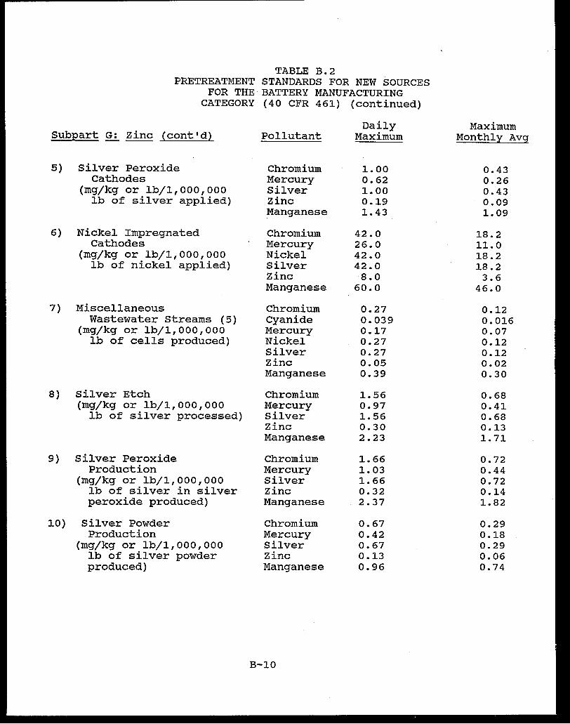
TABLE B.2 PRETREATMENT STANDARDS FOR NEW SOURCES
FOR THE BATTERY MANUFACTURING CATEGORY (40 CFR 461) (continued)
Daily Maximum Subpart G: Zinc (cont'd) Pollutant Maximum Monthly Avg
5) Silver Peroxide Chromium 1.00 0.43 Cathodes Mercury 0.62 0.26
(mg/kg or lb/1,000,000 Silver 1. 00 0.43 lb of silver applied) Zinc 0.19 0.09
Manganese 1.43 1. 09
6) Nickel Impregnated Chromium 42.0 18.2 Cathodes Mercury 26.0 11.0
(mg/kg or lb/1,000,000 Nickel 42.0 18.2 lb of nickel applied) Silver 42.0 18.2
Zinc 8.0 3.6 Manganese 60.0 46.0
7) Miscellaneous Chromium 0.27 0.12 Wastewater Streams (5) Cyanide 0.039 0.016
(mg/kg or lb/1,000,000 Mercury 0.17 0.07 lb of cells produced) Nickel 0.27 0.12
Silver 0.27 0.12 Zinc 0.05 0.02 Manganese 0.39 0.30
8) Silver Etch Chromium 1.56 0.68 (mg/kg or lb/1,000,000 Mercury 0.97 0.41
lb of silver processed) Silver 1.56 0.68 Zinc 0.30 0.13 Manganese 2.23 1. 71
9) Silver Peroxide Chromium 1.66 0.72 Production Mercury 1.03 0.44
(mg/kg or lb/1,000,000 Silver 1. 66 0.72 lb of silver in silver Zinc 0.32 0.14 peroxide produced) Manganese 2.37 1.82
10) Silver Powder Chromium 0.67 0.29 Production Mercury 0.42 0.18
(mg/kg or lb/1,000,000 Silver 0.67 0.29 lb of silver powder Zinc 0.13 0.06 produced) Manganese 0.96 0.74
B-10
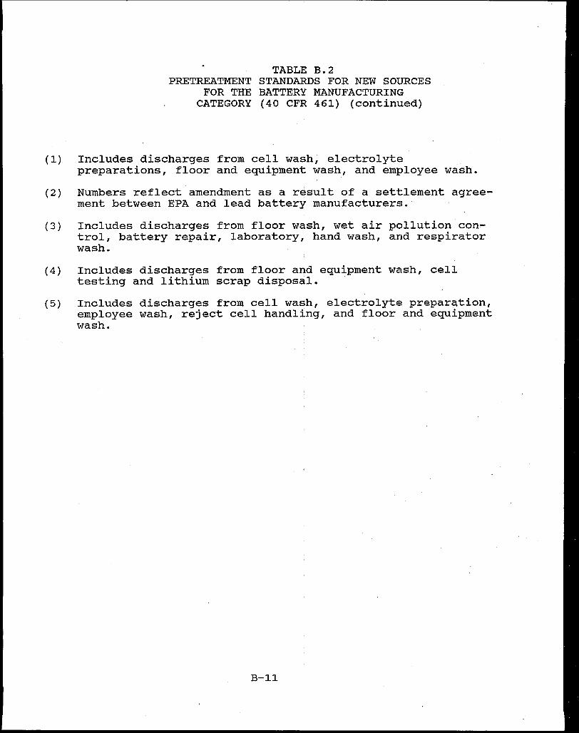
(1)
(2)
(3)
(4)
(5)
TABLE B.2 PRETREATMENT STANDARDS FOR NEW SOURCES
FOR THE BATTERY MANUFACTURING CATEGORY (40 CFR 461) (continued)
Includes discharges from cell wash, electrolyte preparations, floor and equipment wash, and employee wash.
Numbers reflect amendment as a result of a settlement agreement between EPA and lead battery manufacturers.
Includes discharges from floor wash, wet air pollution con~ trol, battery repair, laboratory, hand wash, and respirator wash.
Includes discharges from floor and equipment wash, cell testing and lithium scrap disposal. ·
Includes discharges from cell wash, electrolyte preparation, employee wash, reject cell handling, and floor and equipment wash.
B-11

APPENDIX C
EPA AND STATE PRETREATMENT COORDINATORS

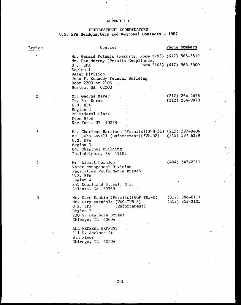
Region
1
2
3
4
5
APPENDIX C
PRETREATMENT COORDINATORS U.S. EPA Headquarters and Regional Contacts ~ 1987
Contact
Mr. Gerald Potamis (Permits, Room 2203) Mr. Dan Murray (Permits Compliance, U.S. EPA Room 2103) Region 1 Water Division John F. Kennedy Federal Building Room 2203 or 2103 Boston, MA 02203
Mr. George Meyer Mr. Pat Durak U.S. EPA Region 2 26 Federal Plaza Room 845A New York, NY 10278
Ms. Charlene Harrison (Permits)(3WM-51) Mr. John Lovell (Enforcement)(3WM-52) U.S. EPA Region 3 841 Chestnut Building Philadelphia, PA 19107
Mr. Albert Herndon Water Management Division Facilities Performance Branch U.S. EPA , Region 4 345 Courtland Street, N.E. Atlanta, GA 30365 ·
Mr. Dave Rankin (Permits)(WQP-TUB~8) Mr. Gary Amendola (WQC-TUB-8) U.S. EPA (Enforcement) Region 5 230 S. Dearborn Street Chicago, IL 60604
ALL FEDERAL EXPRESS 111 W. Jackson St. 8th Floor Chicago, IL 60604
C-1
Phone Numbers
(617) 565-3519
(617) 565-3500
(212) 264-2676 (212) 264-9878
(215) 597-9406 (215) 597-6279
(404) 347-2211
(312) 886-6111 (312) 353-:2105

Region
6
7
8
9
10
Headquarters -Permits
PRETREATMENT COORDINATORS (Continued)
Contact
Mr. Lee Bohme (Permits)(6W-PM) Ms. Wren Stenger (Enforcement) U.S. EPA Region 6 Allied Bank Tower at Fountain Place 1445 Ross Avenue Dallas, TX 75270
Mr. Lee Duvall (WACM) U.S. EPA Region 7 726 Minnesota Avenue Kansas City, KS 66101
Mr. Marshall Fischer (8WM-C) Ms. Dana Allen U.S. EPA Region 8 1 Denver Place 999 18th St., Suite 500 Denver, CO 80202-2405
Mr. Keith Silva (Permits)(W-5-1) Ms. Christine Wright-Shacklett U.S. EPA (Enforcement)(W-5) Region 9 215 Fremont Street San Francisco, CA 94105
Mr. Robert Robichaud (M/S 521)(Permits) Mr. Bill Chamberlin (Enforcement) U.S. EPA Region 10 Permits Branch 1200 Sixth Avenue Seattle, WA 98101
Permits Division U.S. Environmental Protection Agency 401 M Street, S.W. Washington, DC 20460
Mr. William Diamond (EN-336) Chief, Program Implementation Branch Room 214, N.E. Mall
Mr. Tim Dwyer (EN-336) Environmental Engineer Technical Support Branch Room 208, N.E. Mall
C-2
Phone Numbers
(214) 655-7175 (214) 655-6470
(913) 236-2817
(303) 293-1592 (303) 293-1593
(415) 974-8298 (415) 974-8311
(206) 442-1448
(202) 475-9537
(202) 475-9526
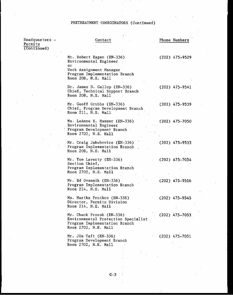
Headquarters -Permits (Continued)
PRETREATMENT COORDINATORS (Continued)
Contact
Mr. Robert Eagen (EN-336) Environmental Engineer or Work Assignment Manager · Program Implementation Branch Room 208, N.E. Mall
Dr. James D. Gallup (EN~336) Chief, Technical Support Branch Room 208, N.E. Mall
Mr. Geoff Grubbs (EN-336) Chief, Program Development Branch Room 211, N.E. Mall
Ms. LeAnne E. Hammer (EN-336) Environmental Engineer Program Development Branch Room 2702, N.E. Mall
Mr. Craig Jakubowics (EN-336) Program Implementation ~ranch _ Room 208, N.E. Mall
Mr. Tom Laverty (EN-336) Section Chief, Program Implementation Branch Room 2702, N.E. Mall
Mr. Ed Ovsenik (EN-336) Program Implementation Branch Room 214, N.E. Mall
Ms. Martha Prothro (EN-336) Director, Permits Division Room 214, N.E. Mall
Mr. Chuck Prorok (EN-336) Environmental Protection Specialist Program Implementation Branch Room 2702, N.E. Mall
Mr. Jim Taft (EN-336) Program Development Branch Room 2702, N.E. Mall
C-3
Phone Numbers
(202) 475-9529
(202) 475-9541
(202) 475-9539
(202) 475-7050
(202) 475--9533
(202) 475-7054
(202) 475-9516
(202) 475-9545
(202) 475-7053
(202) 475-7051
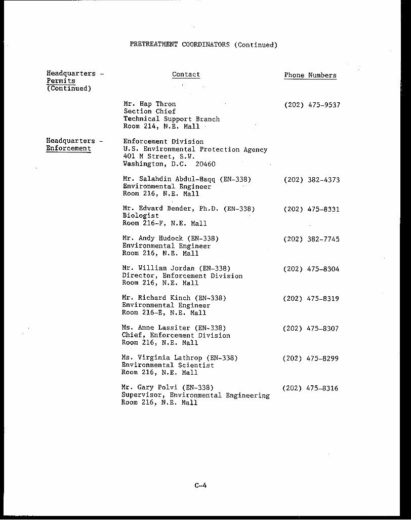
Headquarters -Permits (Continued)
Headquarters -Enforcement
PRETREATMENT COORDINATORS (Continued)
Contact
Mr. Hap Thron Section Chief Technical Support Branch Room 214, N.E. Mall
Enforcement Division U.S. Environmental Protection Agency 401 M Street, S.W. Washington, D.C. 20460
Mr. Salahdin Abdul-Haqq (EN-338) Environmental Engineer Room 216, N.E. Mall
Mr. Edward Bender, Ph.D. (EN-338) Biologist Room 216-F, N.E. Mall
Mr. Andy Hudock (EN-338) Environmental Engineer Room 216, N.E. Mall
Mr. William Jordan (EN-338) Director, Enforcement Division Room 216, N.E. Mall
Mr. Richard Kinch (EN-338) Environmental Engineer Room 216-E, N.E. Mall
Ms. Anne Lassiter (EN-338) Chief, Enforcement Division Room 216, N.E. Mall
Ms. Virginia Lathrop (EN-338) Environmental Scientist Room 216, N.E. Mall
Mr. Gary Polvi (EN-338) Supervisor, Environmental Engineering Room 216, N.E. Mall
C-4
Phone Numbers
(202) 475-9537
(202) 382-4373
(202) 475-8331
(202) 382-7745
(202) 475-8304
(202) 475-8319
(202) 475-8307
(202) 475-8299
(202) 475-8316
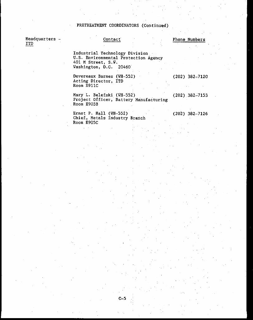
Headquarters -ITO
PRE'l'REATMENT COORDINATORS (Continu~d)
Contact
Industrial Technology Division U.S. Environmental Protection Agency 401 M Street, s.V. Washington, D.C. 204~0 .
Phone . Numb.ers
Devereaux Barnes (WH-552) (202) 382~7120 Acting Director, I'l'D Room J;!911C
Mary L. Belefski (VH-552,) (202). 382-7153 Project Officer, Battery Manufacturing Room E905B
Ernst P. Hall (Wa-552) (202) 382-7126 Chief, Metals Industry Branch Room E905C ·
C-5
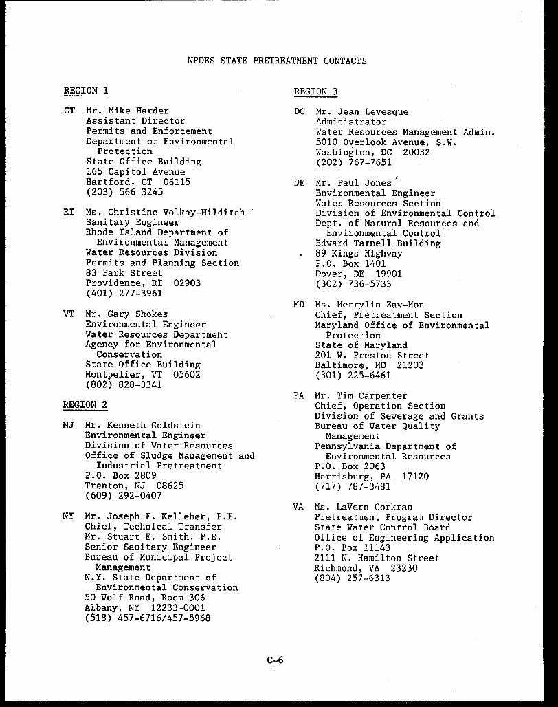
NPDES STATE PRETREATMENT CONTACTS
REGION 1
CT Mr. Mike Harder Assistant Director Permits and Enforcement Department of Environmental
Protection State Office Building 165 Capitol Avenue Hartford, CT 06115 (203) 566-3245
RI Ms. Christine Volkay-Hilditch Sanitary Engineer Rhode Island Department of
Environmental Management Water Resources Division Permits and Planning Section 83 Park Street Providence, RI 02903 (401) 277-3961
VT Mr. Gary Shokes Environmental Engineer Water Resources Department Agency for Environmental
Conservation State Office Building Montpelier, VT 05602 (802) 828-3341
REGION 2
NJ Mr. Kenneth Goldstein Environmental Engineer Division of Water Resources Office of Sludge Management and
Industrial Pretreatment P.O. Box 2809 Trenton, NJ 08625 (609) 292-0407
NY Mr. Joseph F. Kel~eher, P.E. Chief, Technical Transfer Mr. Stuart E. Smith, P.E. Senior Sanitary Engineer Bureau of Municipal Project
Management N.Y. State Department of
Environmental Conservation 50 Wolf Road, Room 306 Albany, NY 12233-0001 (518) 457-6716/457-5968
C-6
REGION 3
DC Mr. Jean Levesque Administrator Water Resources Management Admin. 5010 Overlook Avenue, S.W. Washington, DC 20032 (202) 767-7651
DE Mr. Paul Jones Environmental Engineer Water Resources Section Division of Environmental Control Dept. of Natural Resources and
Environmental Control Edward Tatnell Building 89 Kings llighway P.O. Box 1401 Dover, DE 19901 (302) 736-5733
MO Ms. Merrylin Zaw-Mon Chief, Pretreatment Section Maryland Office of Environmental
Protection State of Maryland 201 W. Preston Street Baltimore, MD 21203 (301) 225-6461
PA Mr. Tim Carpenter Chief, Operation Section Division of Sewerage and Grants Bureau of Water Quality
Management Pennsylvania Department of
Environmental Resources P.O. Box 2063 Harrisburg, PA 17120 (717) 787-3481
VA Ms. Lavern Corkran Pretreatment Program Director State Water Control Board Office of Engineering Application P.O. Box 11143 2111 N. Hamilton Street Richmond, VA 23230 (804) 257-6313
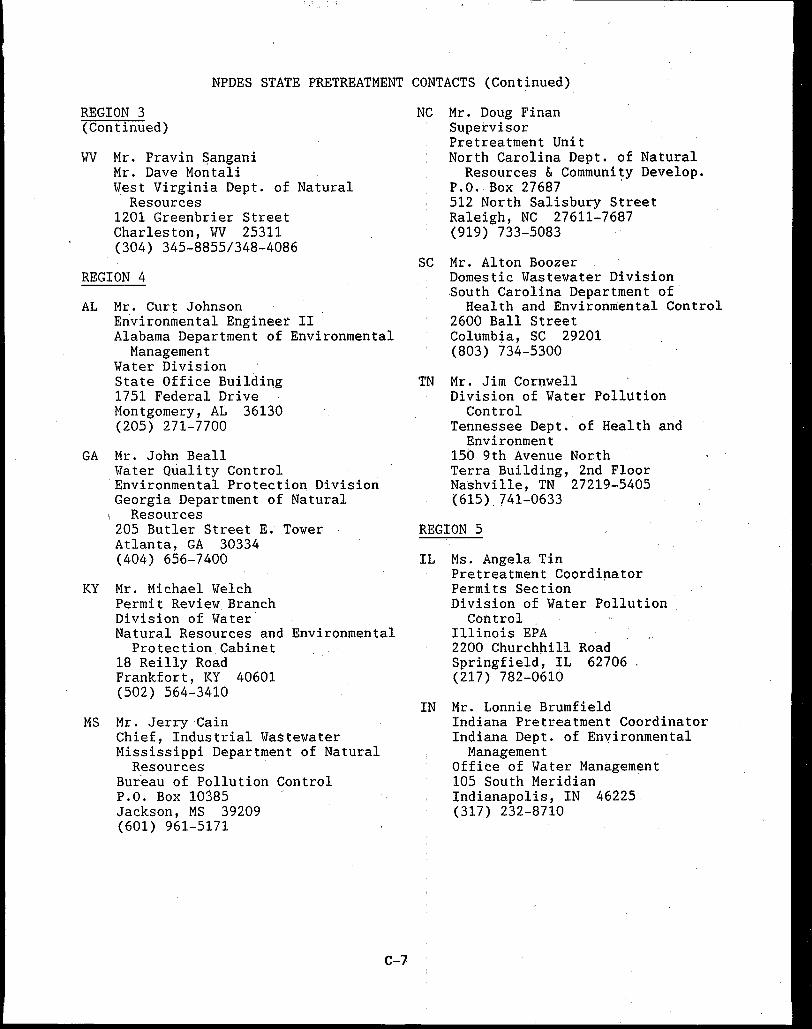
NPDES STATE PRETREATMENT CONTACTS (Continued)
REGION 3 (Continued)
'WV Mr. Pravin Sangani Mr. Dave Mon tali. West Virginia Dept. of Natural
Resources 1201 Greenbrier Street Charleston, 'WV 25311 (304) 345-8855/348-4086
REGION 4
AL Mr. Curt: Johnson Erivironmental Engineer II Alabama Department of Environmental
Management Water Division State Office Building 1751 Federal Drive Montgomery, AL 36130 (205) 271-7700
GA Mr. John Beall Water Quality Control Environmental Protection Division Georgia Department of Natural
Resources 205 Butler Street E. Tower Atlanta, GA 30334 (404) 656-7400
KY Mr. Michael Welch Permit Review Branch Division of Water Natural Resources and Environmental
Protection Cabinet 18 Reilly Road Frankfort, KY 40601 (502) 564-3410
MS Mr. Jerry Cain Chief, Industrial Wastewater Mississippi Department of Natural
Resources Bur.eau of Pollution Control P.O. Box 10385 Jackson, MS 39209 (601) 961-5171
C-7
NC Mr. Doug Finan Supervisor Pretreatment Unit North Carolina Dept. of Natural
Resources & Community Develop. P.O. Box 27687 . 512 North Salisbury Street Raleigh, NC 27611-7687 (919) 733-5083
S~ Mr. Alton Boozer Domestic Wastewater Division South Carolina Department of
Health and Environmental Control 2600 Ball Street Columbia, SC 29201 (803) 734"'.'"5300
TN Mr. Jim Cornwell Division of Water Pollution
Control Tennessee Dept. of Health and
Environment 150 9th Avenue North Terra Building, 2nd Floor Nashville, TN 27219-5405 (615). 741-0633
REGION 5
IL Ms. Angela Tin Pretreatment Coordinator Permits Section Division of Water Pollution
Control Illinois EPA 2200 Churchhill Road Springfield, IL 62706 (217) 782-0610
IN Mr. Lonnie Brumfield Indiana Pretreatment Coordinator Indiana Dept. of Environmental
Management Office of Water Management 105 South Meridian Indianapolis, IN 46225 (317) 232-8710
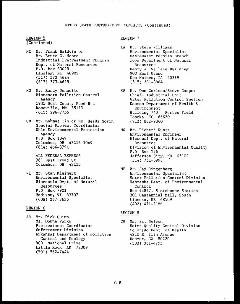
NPDES STATE PRETREATMENT CONTACTS (Continued)
REGION 5 (Continued)
MI Mr. Frank Baldwin or Mr. Bruce c. Moore Industrial Pretreatment Program Dept. of Natural Resources P.O. Box 30028 Lansing, MI 48909 (517) 373-4624 (517) 373-4625
MN Mr. Randy Dunnette Minnesota Pollution Control
Agency 1935 West County Road B-2 Roseville, MN 55113 (612) 296-7756
OH Mr. Mehmet Tin or Ms. Heidi Sorin Special Project Coordinator Ohio Environmental Protection
Agency · P.O. Box 1049 Columbus, OH 43216-1049 (614) 466-3791
ALL FEDERAL EXPRESS 361 East Broad St. Columbus, OH 43215
WI Mr. Stan Klein~rt Environmental Specialist Wisconsin Dept. of Natural
Resources P.O. Box 7921 Madison, WI 53707 (608) 267-7635
REGION 6
AR Mr. Dick Quinn Ms. Donna Parks Pretreatment Coordinator Enforcement Division Arkansas Department of Pollution
Control and Ecology 8001 National Drive Little Rock, AR 72009 (501) 562-7444
REGION 7
IA Mr. Steve Williams Environmental Specialist Wastewater Permits Branch Iowa Department of Natural
Resources Henry A. Wallace Building 900 East Grand Des Moines, IA 50319 (515) 281-8884
KS Mr. Don Carlson/Steve Casper Chief, Industrial Unit Water Pollution Control Section Kansas Department of Health &
Environment Building 740 - Forbes Field Topeka, KS 66620 (913) 862-9360
MO Mr. Richard Kuntz Environmental Engineer' Missouri Dept. of Natural
Resources Division of Environmental Quality P.O. Box 176 Jefferson City, MO 65102 (314) 751~6996
NE Mr. Jay Ringenberg Environmental Specialist Water Pollution Control Division Nebraska Dept. of Environmental
Control Box 94877, Statehouse Station 301 Centennial Mall, South Lincoln, NE 68509 (402) 471-2186
REGION 8
CO Ms. Pat Nelson
C-8
Water Quality Control Division Colorado Dept. of Health 4210 E. 11th Avenue Denver, CO 80220 (303) 331-4755
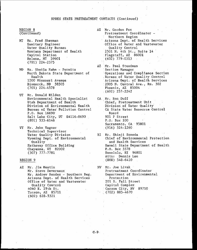
NPDES STATE PRETREATMENT CONTACTS (Continued)
REGION 8 (Continued)
MT Mr. Fred Shewman Sanitary Engineer Water Quality Bureau Montana Department of Health Capitol Station Helena, MT 59601 (701)' 224-2375
ND Ms. Sheila Kuhn - Permits North Dakota State Department of
Health 1200 Missouri Avenue Bismarck, ND 58505 (701) 224-4578
UT Mr. Donald Hilden Environmental Health Specialist Utah Department of Health Division of Environmental Health Bureau of Water Pollution Control P.O. Box 16690 Salt Lake City, UT 84116-0690 (801) 533-6146
WY Mr. John Wagner Technical Supervisor Water Quality Division Wyoming Dept. of Environmental
Quality Hathaway Office Building Cheyenne, WY 82002 (307) 777-7781
REGION 9
AZ Mr. Jim Mestin Mr. Steve Devereaux Mr. Andrew Rendes - Southern Reg. Arizona Dept. of Health Services Office of Water and Wastewater
Quality Control 4040 E. 29th St. Tucson, AZ 85711 (602) 628-5321
AZ Mr. Gordon Fox Pretreatment Coordinator -
Northern Region Arizona Dept. of Health Services Office of Water and Wastewater .. Quality Control 2501 N. 4th St., Suite 14
·Flagstaff, AZ 86001 (602) 779-0313
AZ Mr. Paul Steadman ' Section Manager . Operations and Compliance Section , Bureau. of Water Quality Control ·Arizona Dept. of Health Services : 2005 N. Central Ave., Rm. 302 · Phoenix, AZ 85004 ' (602) 257-2242
CA Mr. Ron Duff ·Chief, Pretreatment Unit . Division of Water Quality
CA State Water Resource Control Board
901 P Street P.O. Box 100 Sacramento, CA 95801 (916) 324-1260 '
HI Mr. Shinji Soneda Chief of Environmental Protection
and Health Services Hawaii State Department of Health P.O. Box 3378 .· Honolulu, HI 96801 Attn: Dennis Lau (808) 548-6410
NV Mr. Joe Livak
C...,.9
Pretreatment Coordinator Department of Environmental
Protection 201 S. Fall Street Capitol Complex Carson City, NV 89710
' (702) 885-46 70
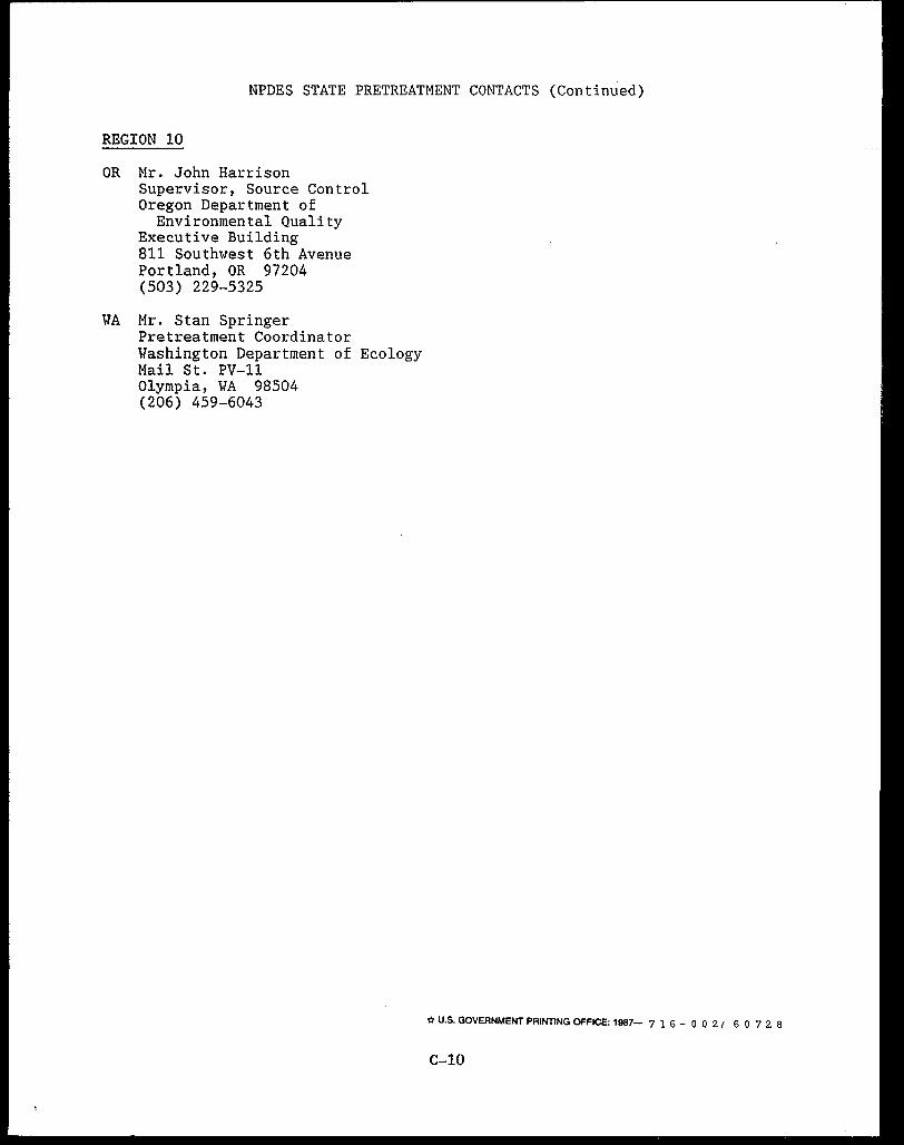
NPDES STATE PRETREATMENT CONTACTS (Continued)
REGION 10
OR Mr. John Harrison Supervisor, Source Control Oregon Department of
Environmental Quality Executive Building 811 Southwest 6th Avenue Portland, OR 97204 (503) 229-5325
VA Mr. Stan Springer Pretreatment Coordinator Washington Department of Ecology Mail St. PV-11 Olympia, WA 98504 (206) 459-6043
-a U.S. GOVERNMENT PRINTING OFFICE: 1987- 7 l 6 - O 0 2 / 6 0 7 2 8
C-10