guidance for obstacle management - caa.gov.om
TRANSCRIPT
Public Authority for Civil Aviation
GUIDANCE FOR OBSTACLE MANAGEMENT
Copyright © 2018 by the Aerodrome Safety Department - DGCAR All rights reserved. No part of this publication may be stored in a retrieval system, transmitted, or reproduced in
any way, including but not limited to photo-copy, magnetic or other record, without the prior agreement and written permission of the DGCAR.
Manual Number: 1.2.10 Issue Date: 12 June 2018 Revision Number: 01
Guidance for Obstacle Management Rev: 01
Date of Issue: 12 June 2018 | Public Authority for Civil Aviation Page ii
List of Effective Pages
Page No.
Rev No. Date of
Issue
Page No.
Rev No. Date of
Issue Page
No. Rev No.
Date of Issue
1 01 12/06/18 41 81
2 01 12/06/18 42 82
3 01 12/06/18 43 83
4 01 12/06/18 44 84
5 01 12/06/18 45 85
6 01 12/06/18 46 86
7 01 12/06/18 47 87
8 01 12/06/18 48 88
9 01 12/06/18 49 89
10 01 12/06/18 50 90
11 01 12/06/18 51 91
12 01 12/06/18 52 92
13 01 12/06/18 53 93
14 01 12/06/18 54 94
15 01 12/06/18 55 95
16 01 12/06/18 56 96
17 01 12/06/18 57 97
18 01 12/06/18 58 98
19 01 12/06/18 59 99
20 01 12/06/18 60 100
21 01 12/06/18 61 101
22 01 12/06/18 62 102
23 01 12/06/18 63 103
24 01 12/06/18 64 104
25 01 12/06/18 65 105
26 01 12/06/18 66 106
27 01 12/06/18 67 107
28 01 12/06/18 68 108
29 01 12/06/18 69 109
30 01 12/06/18 70 110
31 01 12/06/18 71 111
32 01 12/06/18 72 112
33 01 12/06/18 73 113
34 74 114
35 75 115
36 76 116 37 77 117
38 78 118 39 79 119 40 80 120
Guidance for Obstacle Management Rev: 01
Date of Issue: 12 June 2018 | Public Authority for Civil Aviation Page iii
Table of Content FOREWORD ..................................................................................................................................... 1
Purpose of this guidance document ....................................................................................... 2
Definitions ............................................................................................................................... 2
Obstacle Limitation Surfaces .................................................................................................. 4
3.1 General ......................................................................................................................... 4
3.2 Obstacle Restriction ...................................................................................................... 6
3.3 Obstacles Limitation Surface ........................................................................................ 7
3.3.1 The Approach Surface ............................................................................................... 7
3.3.2 The Take-Off Climb Surface ...................................................................................... 7
3.3.3 The Inner Horizontal Surface .................................................................................... 8
3.3.4 The Conical Surface ................................................................................................... 9
3.3.5 The Outer Horizontal Surface ................................................................................... 9
3.3.6 Obstacle-Free Zone ................................................................................................. 10
3.3.7 Surface intersections .............................................................................................. 11
3.4 Practical examples of calculating the maximum Elevation allowed by the OLS ........ 12
Infringement of the Obstacle limitation Surfaces ................................................................ 15
4.1 Principles of Shielding ................................................................................................. 15
4.1.1 Obstacles penetrating the approach and take-off climb surfaces ......................... 16
4.1.2 Obstacles penetrating the inner and outer horizontal and conical surfaces ......... 18
4.1.3 Obstacles Penetrating the Transitional Surfaces .................................................... 18
4.2 Aeronautical Study ..................................................................................................... 19
4.2.1 Obstacle limitation surfaces (OLS) Assessment ...................................................... 20
4.2.2 PAPI protection surface Assessment ...................................................................... 20
4.2.3 ICAO type “A” surface assessment ......................................................................... 21
4.2.4 Significant effect on radio altimeters ..................................................................... 22
4.2.5 Effects on communication, navigation and surveillance facilities .......................... 22
4.2.6 Airport flight procedures ........................................................................................ 23
4.2.7 Safety Risk assessment ........................................................................................... 24
Visual Aids for denoting obstacles ........................................................................................ 26
Procedures for Aerodrome Operators to Deal with Obstacles ............................................ 27
6.1 Responsibilities ........................................................................................................... 27
6.1.1 Obstacle Control ..................................................................................................... 27
6.1.2 Obstacles marking and lighting Control .................................................................. 27
6.2 Training ....................................................................................................................... 28

Guidance for Obstacle Management Rev: 01
Date of Issue: 12 June 2018 | Public Authority for Civil Aviation Page iv
6.3 Duties .......................................................................................................................... 28
6.4 Reporting to PACA ...................................................................................................... 29
References ............................................................................................................................ 29
Guidance for Obstacle Management Rev: 01
Date of Issue: 12 June 2018 | Public Authority for Civil Aviation Page 1
FOREWORD
The safe and regular operation of airports requires that certain precautionary measures be
adopted in order to ensure that no obstacles can hinder the takeoff, holding and approach
procedures, that navigation aids and communications equipment can work without
interference. In order to deal with these issues the common practice is to establish what are
known as "safeguarded areas" in which special measures are adopted. Those zones called
Obstacle limitation Surface was defined by The Basic Aviation Law, Royal Decree No (93/2004)
N° 94/2004 in the articles 6 and 7.
The documents covered are the Civil Aviation Law, Ministerial Decision No. 44/T/2007
(Executive Regulations of the Civil Aviation Law) and CAR 139 “Aerodromes Certification,
Design and Operation”.
This manual is effective from 12 June 2018.

Guidance for Obstacle Management Rev: 01
Date of Issue: 12 June 2018 | Public Authority for Civil Aviation Page 2
Purpose of this guidance document
This guide is intended for the competent departments of the Public Authority for Civil Aviation (PACA)
in charge of the management of the obstacles limitations Surfaces (OLS) and also to the aerodrome
operators responsible for the periodic control of the obstacles inside and outside the aerodrome. It
aims to provide a practical interpretation of CAR 139 provisions and to propose a common
methodology for the development of obstacles limitation surfaces in order to harmonize the practices.
Definitions
When the following terms are used in this DOCUMENT they have the following meanings:
Aerodrome. A defined area on land or water (including any buildings, installations and equipment)
intended to be used either wholly or in part for the arrival, departure and surface movement of
aircraft.
Aerodrome elevation. The elevation of the highest point of the landing area.
Aerodrome reference point. The designated geographical location of an aerodrome.
Balked landing. A landing manoeuvre that is unexpectedly discontinued at any point below the
obstacle clearance altitude/height (OCA/H).
Clearway. A defined rectangular area on the ground or water under the control of the appropriate
authority, selected or prepared as a suitable area over which an aeroplane may make a portion of its
initial climb to a specified height.
Displaced threshold. A threshold not located at the extremity of a runway.
Frangible object. An object of low mass designed to break, distort or yield on impact so as to present
the minimum hazard to aircraft.
Instrument runway. One of the following types of runways intended for the operation of aircraft
using instrument approach procedures:
a. Non-precision approach runway. A runway served by visual aids and a non-visual aid(S) intended
for landing operations following an instrument approach operation type A and a visibility not less
than 1000m.
b. Precision approach runway, category I. A runway served by visual aids and non-visual aid(s)
intended for operations following an instrument approach operation type B with a decision height

Guidance for Obstacle Management Rev: 01
Date of Issue: 12 June 2018 | Public Authority for Civil Aviation Page 3
(DH) not lower than 60 m (200 ft.) and either a visibility not less than 800 m or a runway visual range
not less than 550 m.
c. Precision approach runway, category II. A runway served by visual aids and non-visual aid(s)
intended for landing operations following and instrument approach type B with a decision height
(DH) lower than 60 m (200 ft.) but not lower than 30 m (100 ft.) and a runway visual range not less
than 300 m.
d. Precision approach runway, category III. A runway served by visual aids and non-visual aid(s)
intended for landing operations following and instrument approach type B and along the surface of
the runway and:
A. Intended for operations with a decision height (DH) lower than 30 m (100 ft), or no decision
height and a runway visual range not less than 175 m.
B. Intended for operations with a decision height (DH) lower than 15 m (50 ft), or no decision
height and a runway visual range less than 175 m but not less than 50m
C. Intended for operations with no decision height (DH) and no runway visual range limitations.
Obstacle. All fixed (whether temporary or permanent) and mobile objects, or parts thereof, that:
a. Are located on an area intended for the surface movement of aircraft; or
b. Extend above a defined surface intended to protect aircraft in flight; or
c. Stand outside those defined surfaces and that have been assessed as being a hazard to air navigation.
Obstacle free zone (OFZ). The airspace above the inner approach surface, inner transitional surfaces,
and balked landing surface and that portion of the strip bounded by these surfaces, which is not
penetrated by any fixed obstacle other than a low-mass and frangibly mounted one required for air
navigation purposes.
Outer main gear wheel span (OMGWS). The distance between the outside edges of the main gear
wheels.
Runway. A defined rectangular area on a land aerodrome prepared for the landing and take-off of
aircraft.
Runway end safety area (RESA). An area symmetrical about the extended runway centre line and
adjacent to the end of the strip primarily intended to reduce the risk of damage to an aeroplane
undershooting or overrunning the runway.
Runway strip. A defined area including the runway and stopway, if provided, intended:

Guidance for Obstacle Management Rev: 01
Date of Issue: 12 June 2018 | Public Authority for Civil Aviation Page 4
a) To reduce the risk of damage to aircraft running off a runway; and
b) To protect aircraft flying over it during take-off or landing operations.
Take-off runway. A runway intended for take-off only
Threshold. The beginning of that portion of the runway usable for landing.
Obstacle Limitation Surfaces
3.1 General
In order to protect aircraft against potential collision risk, it is necessary to implement rules regarding
tall structures surrounding aerodromes. This is done via the implementation and safeguarding
of Obstacle Limitation Surfaces or Protected Surfaces as detailed in the CAR 139 – Chapter 4.
The Obstacle Limitation Surfaces (OLS) are conceptual (imaginary) surfaces associated with a runway,
which identify the lower limits of the aerodrome airspace above which objects become obstacles to
aircraft operations, and must be reported to PACA.
Note: The term OLS is used to refer to each of the imaginary surfaces which together define the lower
boundary of aerodrome airspace, as well as to refer to the complex imaginary surface formed by
combining all the individual surfaces.

Guidance for Obstacle Management Rev: 01
Date of Issue: 12 June 2018 | Public Authority for Civil Aviation Page 5
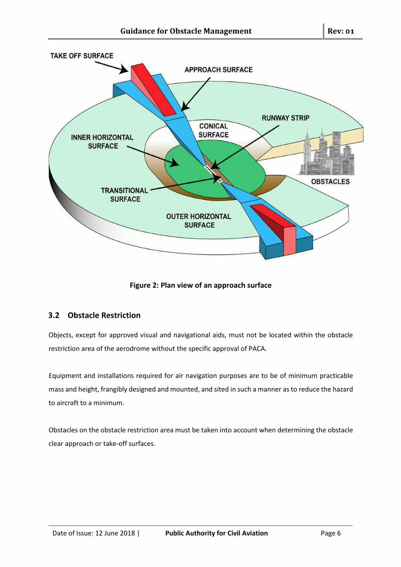
Figure 1: Relevance of Obstacle Limitation Surfaces
The OLS comprises the following:
(a) outer horizontal surface;
(b) conical surface;
(c) inner horizontal surface;
(d) approach surface;
(e) inner approach surface;
(f) transitional surface;
(g) inner transitional surface;
(h) baulked landing surface; and
(i) take-off climb surface.
Guidance for Obstacle Management Rev: 01
Date of Issue: 12 June 2018 | Public Authority for Civil Aviation Page 6
Figure 2: Plan view of an approach surface
3.2 Obstacle Restriction Objects, except for approved visual and navigational aids, must not be located within the obstacle
restriction area of the aerodrome without the specific approval of PACA.
Equipment and installations required for air navigation purposes are to be of minimum practicable
mass and height, frangibly designed and mounted, and sited in such a manner as to reduce the hazard
to aircraft to a minimum.
Obstacles on the obstacle restriction area must be taken into account when determining the obstacle
clear approach or take-off surfaces.
Guidance for Obstacle Management Rev: 01
Date of Issue: 12 June 2018 | Public Authority for Civil Aviation Page 7
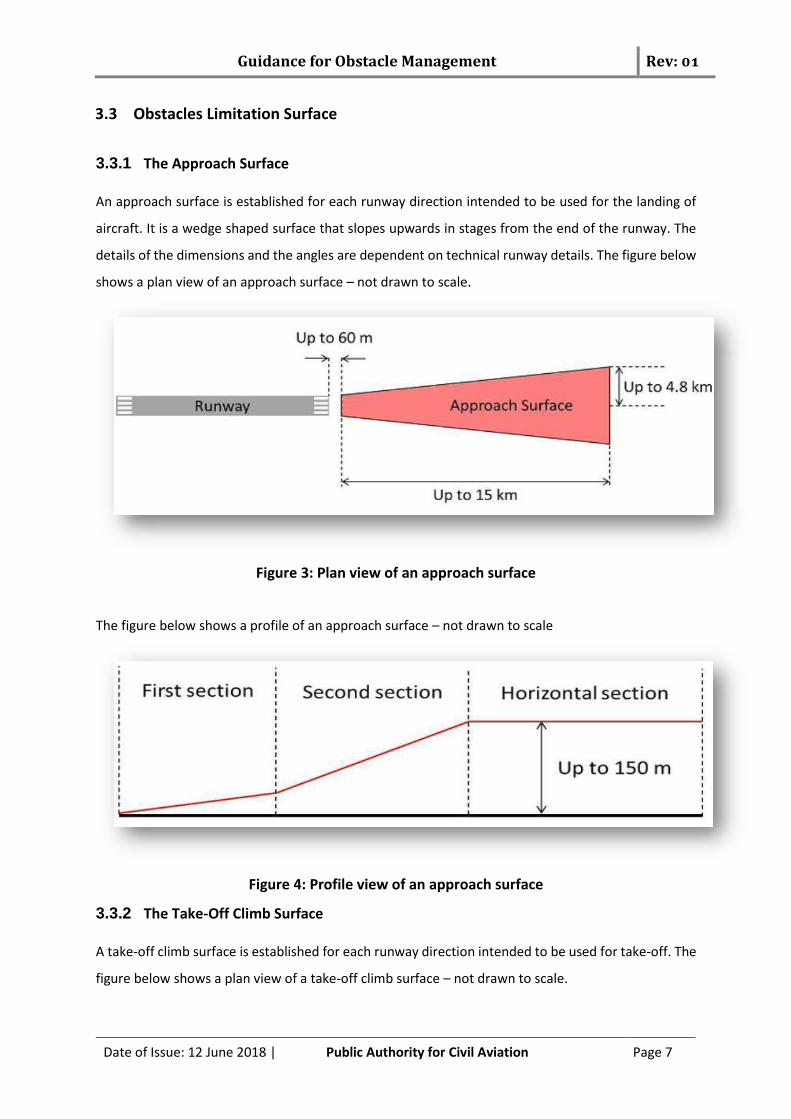
3.3 Obstacles Limitation Surface
3.3.1 The Approach Surface An approach surface is established for each runway direction intended to be used for the landing of
aircraft. It is a wedge shaped surface that slopes upwards in stages from the end of the runway. The
details of the dimensions and the angles are dependent on technical runway details. The figure below
shows a plan view of an approach surface – not drawn to scale.
Figure 3: Plan view of an approach surface
The figure below shows a profile of an approach surface – not drawn to scale
Figure 4: Profile view of an approach surface
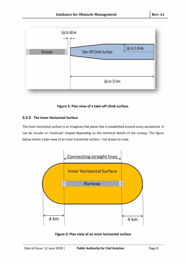
3.3.2 The Take-Off Climb Surface A take-off climb surface is established for each runway direction intended to be used for take-off. The
figure below shows a plan view of a take-off climb surface – not drawn to scale.
Guidance for Obstacle Management Rev: 01
Date of Issue: 12 June 2018 | Public Authority for Civil Aviation Page 8
Figure 5: Plan view of a take-off climb surface.
3.3.3 The Inner Horizontal Surface The inner horizontal surface is an imaginary flat plane that is established around every aerodrome. It
can be circular or ‘racetrack’ shaped depending on the technical details of the runway. The figure
below shows a plan view of an inner horizontal surface – not drawn to scale.
Figure 6: Plan view of an inner horizontal surface

Guidance for Obstacle Management Rev: 01
Date of Issue: 12 June 2018 | Public Authority for Civil Aviation Page 9
The height of the surface is continuous and is defined relative to the lowest runway threshold at the
aerodrome.
3.3.4 The Conical Surface A conical surface extends outwards from the edge of the inner horizontal surface described above.
The conical surface slopes upwards away from the runway at a uniform angle from start to finish.
The figure below shows a plan view of an inner horizontal surface – not drawn to scale.
Figure 7: Plan view of a conical surface.
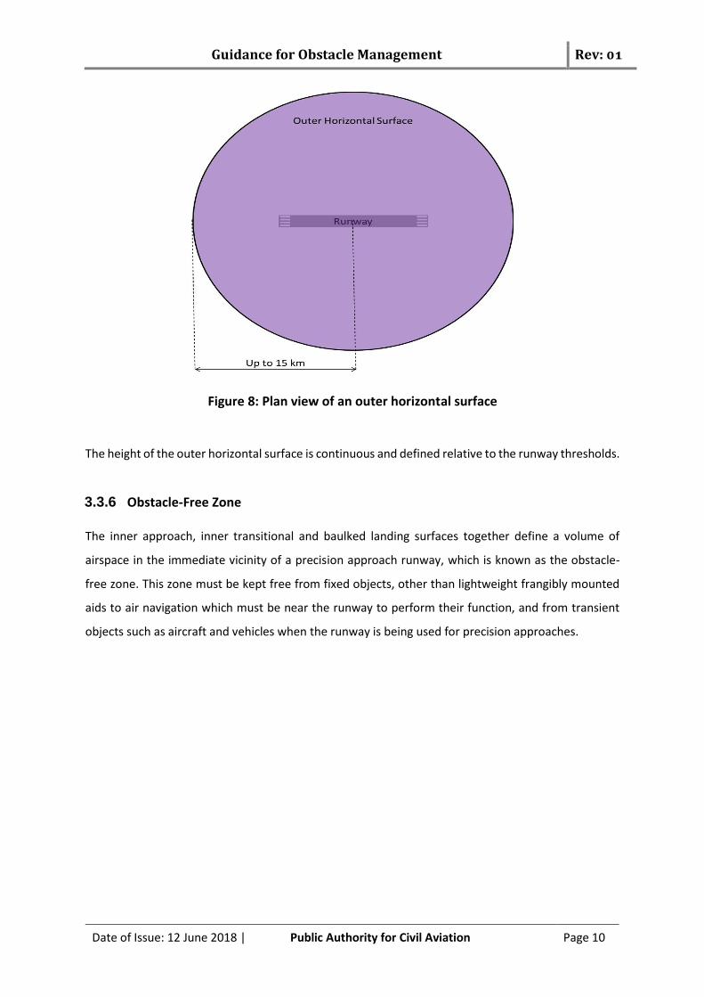
3.3.5 The Outer Horizontal Surface The outer horizontal surface is an imaginary circular flat plane that is established around aerodromes.
The figure below shows a plan view of an outer horizontal surface – not drawn to scale.
Guidance for Obstacle Management Rev: 01
Date of Issue: 12 June 2018 | Public Authority for Civil Aviation Page 10
Figure 8: Plan view of an outer horizontal surface
The height of the outer horizontal surface is continuous and defined relative to the runway thresholds.
3.3.6 Obstacle-Free Zone The inner approach, inner transitional and baulked landing surfaces together define a volume of
airspace in the immediate vicinity of a precision approach runway, which is known as the obstacle-
free zone. This zone must be kept free from fixed objects, other than lightweight frangibly mounted
aids to air navigation which must be near the runway to perform their function, and from transient
objects such as aircraft and vehicles when the runway is being used for precision approaches.
Guidance for Obstacle Management Rev: 01
Date of Issue: 12 June 2018 | Public Authority for Civil Aviation Page 11
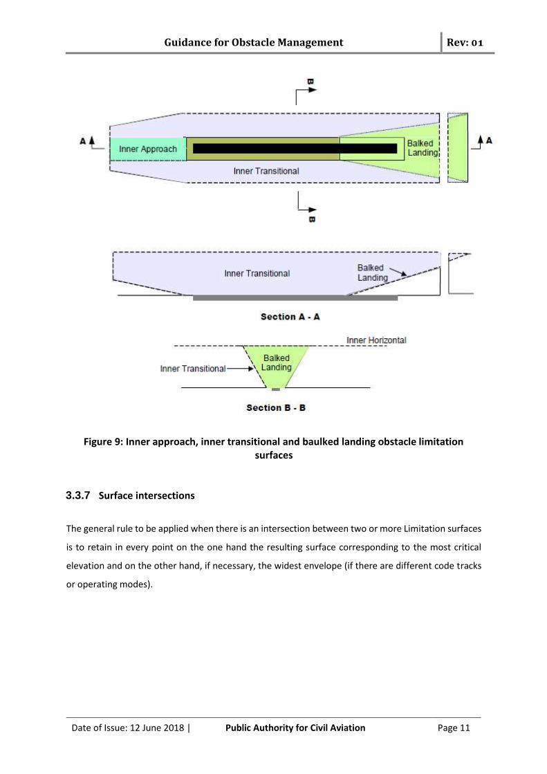
Figure 9: Inner approach, inner transitional and baulked landing obstacle limitation surfaces
3.3.7 Surface intersections
The general rule to be applied when there is an intersection between two or more Limitation surfaces
is to retain in every point on the one hand the resulting surface corresponding to the most critical
elevation and on the other hand, if necessary, the widest envelope (if there are different code tracks
or operating modes).
Guidance for Obstacle Management Rev: 01
Date of Issue: 12 June 2018 | Public Authority for Civil Aviation Page 12
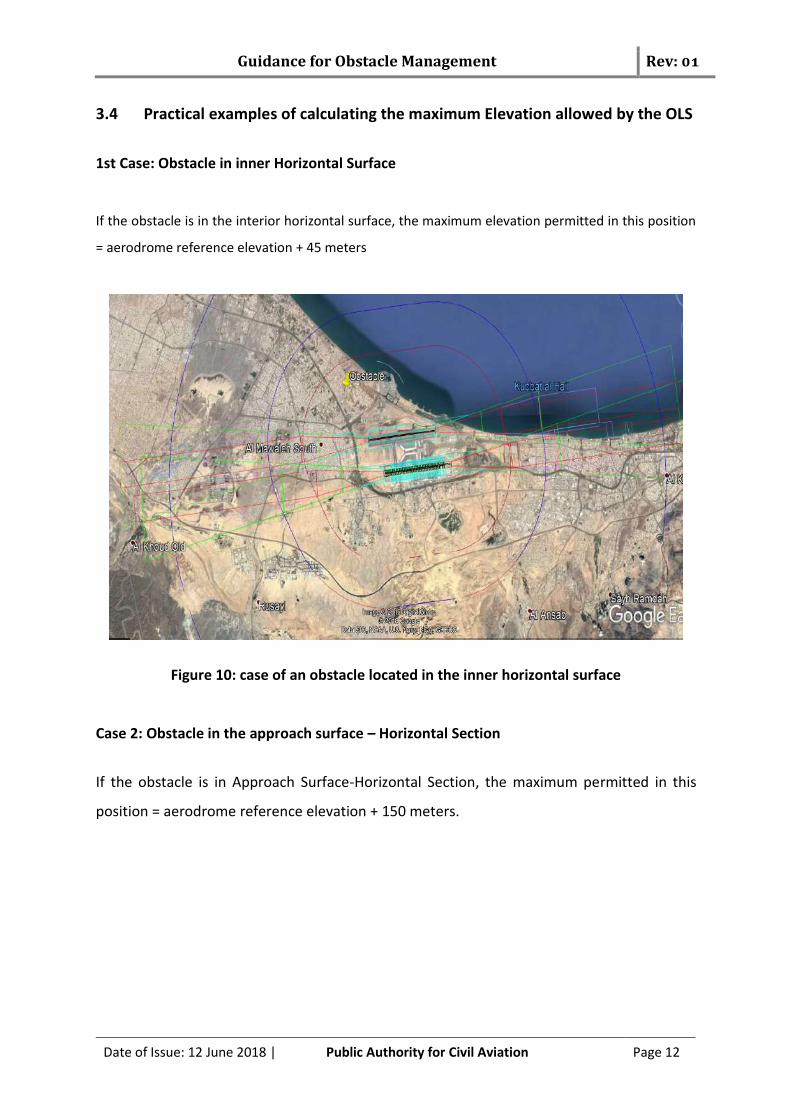
3.4 Practical examples of calculating the maximum Elevation allowed by the OLS
1st Case: Obstacle in inner Horizontal Surface
If the obstacle is in the interior horizontal surface, the maximum elevation permitted in this position
= aerodrome reference elevation + 45 meters
Figure 10: case of an obstacle located in the inner horizontal surface
Case 2: Obstacle in the approach surface – Horizontal Section
If the obstacle is in Approach Surface-Horizontal Section, the maximum permitted in this
position = aerodrome reference elevation + 150 meters.
Guidance for Obstacle Management Rev: 01
Date of Issue: 12 June 2018 | Public Authority for Civil Aviation Page 13
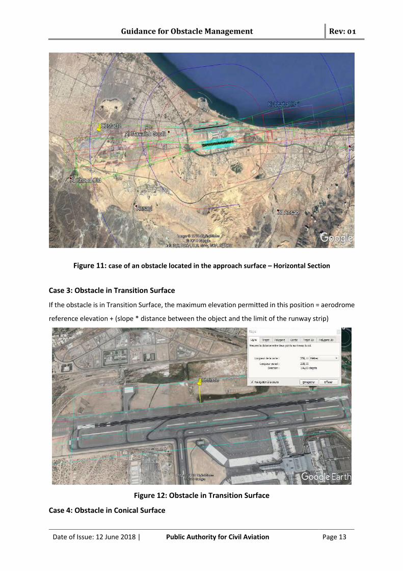
Figure 11: case of an obstacle located in the approach surface – Horizontal Section
Case 3: Obstacle in Transition Surface
If the obstacle is in Transition Surface, the maximum elevation permitted in this position = aerodrome
reference elevation + (slope * distance between the object and the limit of the runway strip)
Figure 12: Obstacle in Transition Surface
Case 4: Obstacle in Conical Surface
Guidance for Obstacle Management Rev: 01
Date of Issue: 12 June 2018 | Public Authority for Civil Aviation Page 14
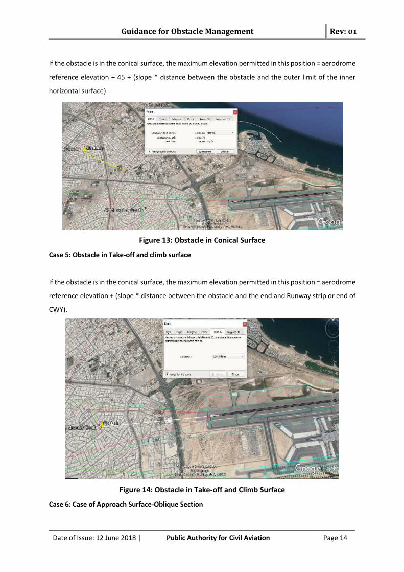
If the obstacle is in the conical surface, the maximum elevation permitted in this position = aerodrome
reference elevation + 45 + (slope * distance between the obstacle and the outer limit of the inner
horizontal surface).
Figure 13: Obstacle in Conical Surface
Case 5: Obstacle in Take-off and climb surface
If the obstacle is in the conical surface, the maximum elevation permitted in this position = aerodrome
reference elevation + (slope * distance between the obstacle and the end and Runway strip or end of
CWY).
Figure 14: Obstacle in Take-off and Climb Surface
Case 6: Case of Approach Surface-Oblique Section

Guidance for Obstacle Management Rev: 01
Date of Issue: 12 June 2018 | Public Authority for Civil Aviation Page 15
If the obstacle is in the approach surface-Oblique Section, the permitted in this position = aerodrome
reference elevation + Maximum Elevation permitted in previous section (slope in this section *
distance between the object and the limit of the previous section).
Figure 15: Obstacle in Approach Surface-Oblique Section
Infringement of the Obstacle limitation Surfaces
The CAR 139-Part1 (Chapter 4) states that if an obstacle infringe the Obstacle Limitation Surface (OLS)
shall not be authorized except when, in the opinion of PACA, the object would be shielded by an
existing immovable object, or after aeronautical study it is determined that the object would not
adversely affect the safety or significantly affect the regularity of operations of aeroplanes.
4.1 Principles of Shielding The principle of shielding is employed when a substantial and permanent object or natural terrain
already penetrates an obstacle limitation surface. When it is considered that such an obstacle is
permanent, objects of equal or lesser height around it may, at the PACA’s discretion, be permitted to
penetrate the surface.
A new obstacle located in the vicinity of an existing obstacle and assessed as not being a hazard to
aircraft is deemed to be shielded. Unless specifically directed by PACA, a shielded obstacle does not
require removal or destruction and should not impose any additional restrictions to aircraft
Guidance for Obstacle Management Rev: 01
Date of Issue: 12 June 2018 | Public Authority for Civil Aviation Page 16
operations. Only existing permanent obstacles may be considered in assessing shielding of new
obstacles.
In assessing whether an existing obstacle shields an obstacle, PACA will be guided by the principles of
shielding detailed below.
4.1.1 Obstacles penetrating the approach and take-off climb surfaces
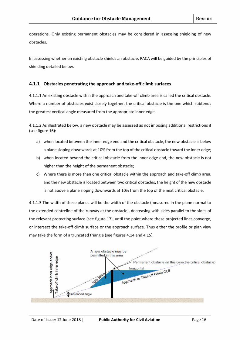
4.1.1.1 An existing obstacle within the approach and take-off climb area is called the critical obstacle.
Where a number of obstacles exist closely together, the critical obstacle is the one which subtends
the greatest vertical angle measured from the appropriate inner edge.
4.1.1.2 As illustrated below, a new obstacle may be assessed as not imposing additional restrictions if (see figure 16):
a) when located between the inner edge end and the critical obstacle, the new obstacle is below
a plane sloping downwards at 10% from the top of the critical obstacle toward the inner edge;
b) when located beyond the critical obstacle from the inner edge end, the new obstacle is not
higher than the height of the permanent obstacle;
c) Where there is more than one critical obstacle within the approach and take-off climb area,
and the new obstacle is located between two critical obstacles, the height of the new obstacle
is not above a plane sloping downwards at 10% from the top of the next critical obstacle.
4.1.1.3 The width of these planes will be the width of the obstacle (measured in the plane normal to
the extended centreline of the runway at the obstacle), decreasing with sides parallel to the sides of
the relevant protecting surface (see figure 17), until the point where these projected lines converge,
or intersect the take-off climb surface or the approach surface. Thus either the profile or plan view
may take the form of a truncated triangle (see figures 4.14 and 4.15).

Guidance for Obstacle Management Rev: 01
Date of Issue: 12 June 2018 | Public Authority for Civil Aviation Page 17
Figure 16: Shielding of obstacles penetrating the approach and take-off climb surfaces
Figure 17: delimitation of the zone shielded by an obstacle by the approach and take-off climb surfaces
Guidance for Obstacle Management Rev: 01
Date of Issue: 12 June 2018 | Public Authority for Civil Aviation Page 18
4.1.2 Obstacles penetrating the inner and outer horizontal and conical surfaces The new obstacle may be accepted if it is in the vicinity of an existing obstacle, and does not penetrate
a 10% downward sloping conical shaped surface from the top of the existing obstacle, i.e. the new
obstacle is shielded radially by the existing obstacle.
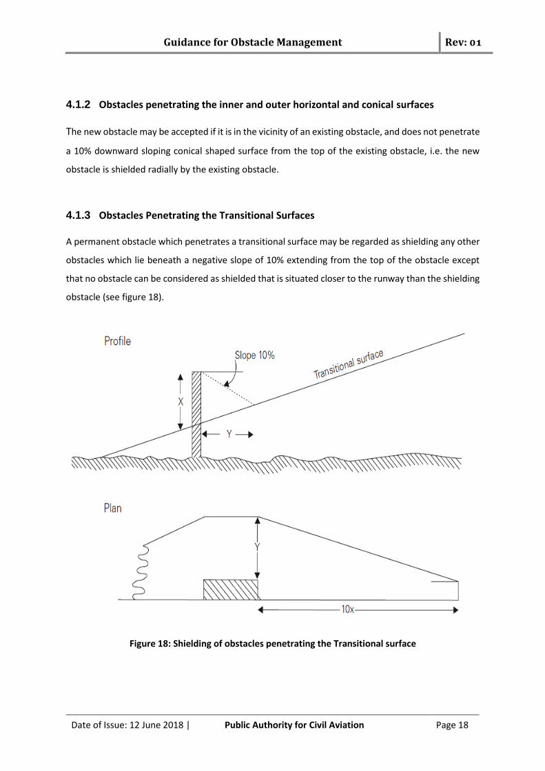
4.1.3 Obstacles Penetrating the Transitional Surfaces A permanent obstacle which penetrates a transitional surface may be regarded as shielding any other
obstacles which lie beneath a negative slope of 10% extending from the top of the obstacle except
that no obstacle can be considered as shielded that is situated closer to the runway than the shielding
obstacle (see figure 18).
Figure 18: Shielding of obstacles penetrating the Transitional surface
Guidance for Obstacle Management Rev: 01
Date of Issue: 12 June 2018 | Public Authority for Civil Aviation Page 19
4.2 Aeronautical Study When the shielding principal mentioned in the paragraph 3.1 cannot be satisfied, the Obstacle Owner
must conduct an aeronautical study in order assess the potential impact that this obstacle may have
on aircraft operations as it is shown in the figure 19. For this purpose, the minimum items listed below
will be considered:
- Obstacle limitation surfaces (OLS), including the Obstacle Free Zone (OFZ);
- PAPI obstacle protection surface;
- ICAO type A surface assessment: Any restrictions, that would be imposed on aircraft
operations shall be considered and mitigated;
- Significant effect on radio altimeters (if the obstacle in the Inner approach surface):
demonstration should be made (flight control system is not affected);
- Effects on communication, navigation and surveillance facilities: Two assessments shall
carried out whit regard to CNS facilities:
o Analysis of CNS facilities Building restricted areas (BRA).
o Radio electric simulations for those CNS facilities whose BRA are infringed (and,
when deemed necessary, also for facilities whose BRA are not infringed).
- Airport flight procedures;
- Safety Risk Assessment.

Guidance for Obstacle Management Rev: 01
Date of Issue: 12 June 2018 | Public Authority for Civil Aviation Page 20
Figure 19: Aeronautical study process
4.2.1 Obstacle limitation surfaces (OLS) Assessment The assessment of OLS will include the calculation of the Obstacle Limitation Surface (including OFZ).
All surfaces will be calculated according to CAR 139. In this study, the new obstacles will be evaluated
to answer the following questions:
- Are the OLS infringed?
- What individual surfaces infringed?
- To what extent are the OLS infringed?
4.2.2 PAPI protection surface Assessment The assessment of PAPI’s Obstacle Protection Surface will include the calculation of the PAPI’s
Obstacle Protection Surface according to the CAR 139 – Part 1 ,chapter 4. In this study, the new
obstacles will be evaluated to know if they infringe the surface.

Guidance for Obstacle Management Rev: 01
Date of Issue: 12 June 2018 | Public Authority for Civil Aviation Page 21
According to CAR 139-Part1-Chapter 5, in case of PAPI’s Obstacle Protection Surface infringement the
obstacle must be shielded and an additional safety risk assessment is required. The safety risk
assessment process will be detailed in other guidance material and will include:
- Analyse the risk of the infringement and assess the severity and probability of the risks
identified ;
- Propose the measures to mitigate the risks identified;
- Development of an implementation plan for the mitigation measures and conclusion of the
assessment;
- Determine the level of safety after mitigation.
Where an aeronautical study indicates that an existing object extending above an obstacle protection
surface (OPS) could adversely affect the safety of operations of aeroplanes, one or more of the
following measures shall be taken:
a) remove the object;
b) suitably raise the approach slope of the system;
c) reduce the azimuth spread of the system so that the object is outside the confines of the
beam;
d) displace the axis of the system and its associated obstacle protection surface by no more
than 5°; and
e) suitably displace the system upwind of the threshold such that the object no longer
penetrates the OPS.
4.2.3 ICAO type “A” surface assessment The study must calculate the ICAO Type “A” surface and assess the infringement of this surface. Any
restrictions, that would be imposed on aircraft operations shall be considered and mitigated.

Guidance for Obstacle Management Rev: 01
Date of Issue: 12 June 2018 | Public Authority for Civil Aviation Page 22
4.2.4 Significant effect on radio altimeters The airworthiness certification of aeroplanes for Category II operations demands that the approach
guidance system includes, among others, a radio altimeter with displays at each pilot’s station the
radio altitude, and the selected decision height.
The ground profile before the runway considering the new ramp will be examined to determine the
effects of the slopes of the terrain and the irregularities on the performance of the automatic landing
system due to the impact of the radio altimeter.
4.2.5 Effects on communication, navigation and surveillance facilities
The Ministerial decision N° 44/t/2007 (executive regulations of the civil aviation law) and the ICAO’s
EUR DOC 15 “European guidance material on managing Building Restricted Areas” proposes
harmonized protection zones and defines for the most common facilities a building restricted area
(BRA). The BRA is defined as a volume where buildings have the potential to cause unacceptable
interference to the signal-in-space in the service volume of CNS facilities. All CNS facilities have BRAs
defined, which are not limited to actual site boundaries of the facility but extended to significant
distances from the facility.
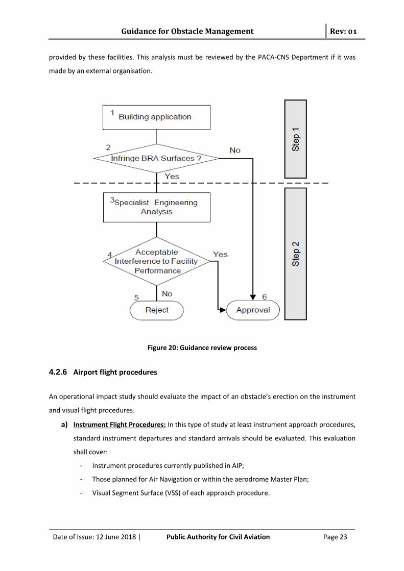
The general procedure to assess the effect on the CNS facilities is a two-step process (see Figure 20)
for the approval of buildings that may adversely affect CNS facilities. The analysis carried out under
both processes should be formally recorded. The intention is that Step 1 should be an expedient
evaluation and Step 2 should involve in-depth analysis.
For Step 1- BRA INFRINGEMENT ANALYSIS: This analysis will be conducted by the appropriate
authorities (for example: Airport, Planning, Local Official, PACA Department who conduct the initial
review of building applications) in order to ascertain whether approval can be given directly or it
should be passed to the appropriate engineering authorities (PACA - CNS Department).
For Step 2- RADIOELECTRIC IMPACT STUDY: A Radio-electric Impact Study will be performed for those
CNS systems whose BRA would be infringed. In fact, the appropriate authorities (CNS Department,
Airport Planning, and Local Official) should carry out detailed analysis. This should cover all aspects of
the CNS facility to be protected and the possible effects of the proposed building on the signal in space
Guidance for Obstacle Management Rev: 01
Date of Issue: 12 June 2018 | Public Authority for Civil Aviation Page 23
provided by these facilities. This analysis must be reviewed by the PACA-CNS Department if it was
made by an external organisation.
Figure 20: Guidance review process
4.2.6 Airport flight procedures
An operational impact study should evaluate the impact of an obstacle’s erection on the instrument
and visual flight procedures.
a) Instrument Flight Procedures: In this type of study at least instrument approach procedures,
standard instrument departures and standard arrivals should be evaluated. This evaluation
shall cover:
- Instrument procedures currently published in AIP;
- Those planned for Air Navigation or within the aerodrome Master Plan;
- Visual Segment Surface (VSS) of each approach procedure.

Guidance for Obstacle Management Rev: 01
Date of Issue: 12 June 2018 | Public Authority for Civil Aviation Page 24
b) Visual Flight Procedures: Visual flight procedures currently published in AIP gathered within
The Visual Approach Chart (VAC), should be checked. The study should check if an aircraft in
visual conditions, on an aerodrome traffic circuit or through the visual tracks with
destination/departure to/from the aerodrome, at the notification points determined within
the VAC, could be affected by the obstacle.
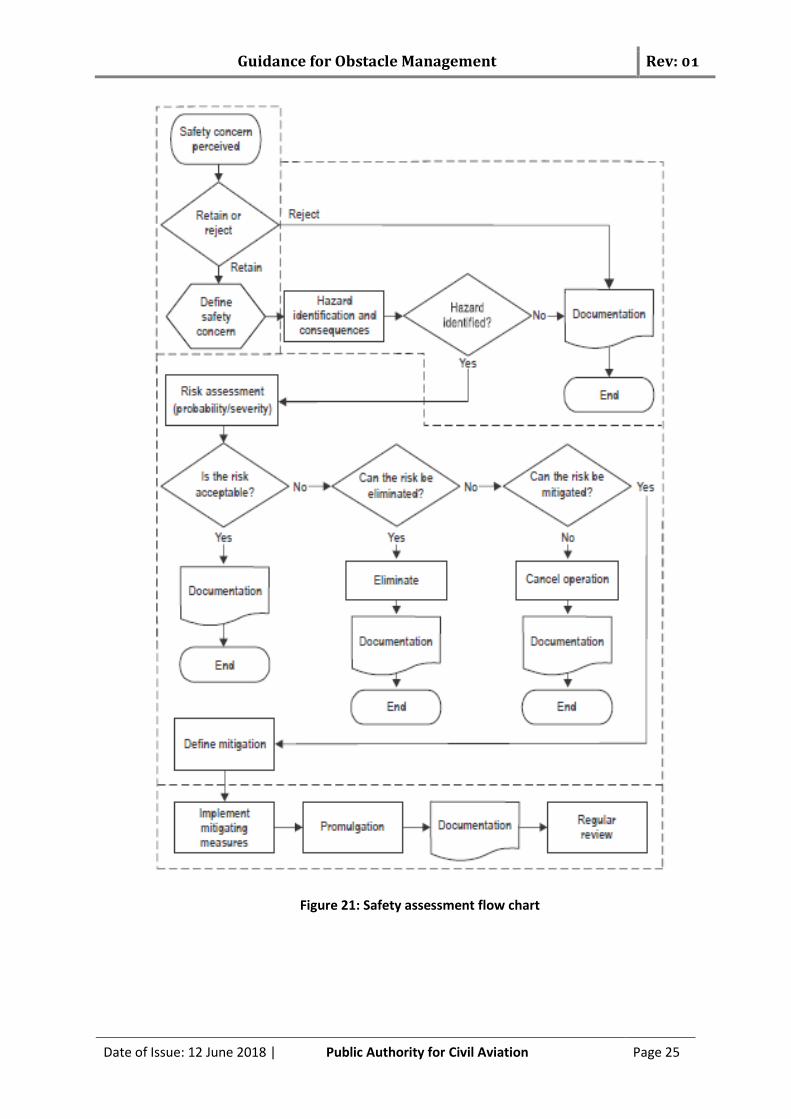
4.2.7 Safety Risk assessment The primary objective of a safety assessment is to assess the impact of a safety concern such as a
design change or deviation in operational procedures or provisions at an existing aerodrome.
Such a safety concern can often impact multiple stakeholders; therefore, safety assessments often
need to be carried out in a cross-organizational manner, involving experts from all the involved
stakeholders. Prior to the assessment, a preliminary identification of the required tasks and the
organizations to be involved in the process is conducted.
The safety risk assessment process will be more detailed in other guidance material (see Figure 21)
and will include at least:
- Analyse the risk of the infringement and assess the severity and probability of the risks
identified.
- Propose the measures to mitigate the risks identified.
- Development of an implementation plan for the mitigation measures and conclusion of the
assessment;
- Determine the level of safety after mitigation.
Guidance for Obstacle Management Rev: 01
Date of Issue: 12 June 2018 | Public Authority for Civil Aviation Page 25
Figure 21: Safety assessment flow chart

Guidance for Obstacle Management Rev: 01
Date of Issue: 12 June 2018 | Public Authority for Civil Aviation Page 26
Visual Aids for denoting obstacles
The CAR 139 PART 1- Chapter 6 requires that pilots be informed of the presence of obstacles by
marking and/or Lighting of each obstacle that may constitute a hazard (see figure 22). The opportunity
of marking/Lighting an obstacle is not limited to areas defined by the clearance surfaces and is to be
assessed according to local conditions, the nature of the obstacle and air navigation procedures.
The obstacles lighting which, by reason of its intensity, configuration or colour, might prevent, or cause
confusion in, the clear interpretation of aeronautical ground lights shall be extinguished, screened or
otherwise modified so as to eliminate such a possibility. In fact, after receiving any notifications from
the pilot related to high intensity of obstacles lighting or another lighting, which can cause confusion,
the aerodrome operator shall take the necessary action to mitigate this hazards.
Figure 22: Visual obstacles for denoting obstacles
Guidance for Obstacle Management Rev: 01
Date of Issue: 12 June 2018 | Public Authority for Civil Aviation Page 27
Procedures for Aerodrome Operators to Deal with Obstacles
6.1 Responsibilities
6.1.1 Obstacle Control
The aerodrome operator must monitor the OLS applicable to the aerodrome and report to PACA any
infringement or potential infringement of the OLS. In fact the Aerodrome operators need to liaise with
appropriate planning authorities and companies that erect tall structures, to determine potential
infringements. Every effort should be made to implement the OLS provisions and limit the introduction
of new obstacles.
Since the area to be controlled is large, the aerodrome operator may set the frequency of obstacle
control by taking into account the following elements:
- Type of surface (approach, conical, ...)
- The topography of the area (sea, mountain, urban area, desert ....)
- The history of the results of previous inspections.
When a new obstacle is detected, the aerodrome operator must ensure that the information is passed
on to pilots, through NOTAM, in accordance with the standards for aerodrome reporting procedures
detailed in the aerodrome manual. The information on any new obstacle must include:
a) the nature of the obstacle — for instance structure or machinery;
b) the geographic coordinates in WGS-84;
c) Elevation (MSL) and height of the obstacle in relation to the aerodrome elevation;
d) If the obstacle is marked / lighted; and
e) If it is a temporary obstacle — the time it is an obstacle.
6.1.2 Obstacles marking and lighting Control
The aerodrome operator must also check if the owners of the obstacles comply with regulations
relating to marking and lighting obstacles (CAR 139 - Chapter 6), both on the aerodrome and in the
vicinity of aerodromes, which could otherwise present a hazard to aircraft. The aerodrome operator
must implement and update an obstacle database in order to achieve this mission.
Guidance for Obstacle Management Rev: 01
Date of Issue: 12 June 2018 | Public Authority for Civil Aviation Page 28
The obstacle database would contain the list of the obstacle contain in the AIP and the obstacle
authorized by PACA witch obstacle marking and/or Lighting. In fact the Aerodrome Safety Department
should inform the Aerodrome operator about the obstacle authorized witch need marking or lighting
in order to plan their control.
6.2 Training The aerodrome operator shall designate a qualified officer to achieve obstacle control mission. This
officer must receive specific training on the obstacle limitation surfaces and he must have the ability
to use the necessary equipment to accomplish his mission.
6.3 Duties When the officer detects an object could become an obstacle, he shall provide to PACA (Aerodrome
Safety Department) in coordination with the owner of this obstacle:
- the geographic coordinates in WGS-84 of the obstacles;
- Elevation (MSL) and height of the obstacle in relation to the aerodrome elevation;
The Aerodrome Safety department will evaluate the obstacle in coordination with the Air Navigation
Safety Department and CNS department in order to assess his impact on the OLS and on the Airport
operation (Flight procedure and CNS Facilities).
After this study:
- The aerodrome operator will be informed in order to take the necessary action.
- The Aerodrome Safety Department will inform the PACA-Legal department in order to take
the necessary action in coordination with the Government Authorities according to Civil
Aviation Law, Royal Decree No (93/2004) - Article N° 7 that stipulate “The Civil Aviation
Authority shall have the right to remove any installations or buildings in these areas that
have been erected without permission or in violation thereof. The violator shall bear the cost
of removal. The Civil Aviation Authority shall remove any installations or buildings if deemed
necessary.”
Guidance for Obstacle Management Rev: 01
Date of Issue: 12 June 2018 | Public Authority for Civil Aviation Page 29
6.4 Reporting to PACA
The aerodrome operator shall send a periodic report to PACA (twice per year). This report contains a
summary of the obstacle inspection mission and the follow up about the obstacles detected and the
actions taken.
References
- Civil Aviation Law, Royal Decree No (93/2004)
- Ministerial Decision No. 44/T/2007 (Executive Regulations of the Civil Aviation Law)
- Civil Aviation Regulation CAR-139
- Civil Aviation Regulation CAR-100
- ICAO Annex 14 – Volume 1- Aerodrome Design and Operations
- ICAO Annex 19, Safety Management
- Airport Services Manual (Doc 9137) - Part 6 — Control of Obstacles
- Manual on Certification of Aerodromes (Doc 9774)
- Safety Management Manual (SMM) (Doc 9859)
- Procedures for Air Navigation Services — Aerodromes (PANS-AERODROMES) (Doc 9981)
- ICAO EUR DOC 015 - European guidance material on managing building restricted areas
- World Geodetic System — 1984 (WGS-84) Manual (Doc 9674)
--- End ---