gsm-information-elements- cac thong so trong tems
TRANSCRIPT

GSM Information ElementsIE Support in Connectable EquipmentSome elements are presentable only with a subset of the connectable devices. See the table in section 5.2.Properties of Information Elements: The Asterisk ColumnIn the column marked *, a set of codes is used to state conditions under which an information element is• valid: a non-trivial condition must be fulfilled for the element to be valid• not valid: the element is normally valid, but in certain circumstances it is not (code ends in “–”)
• extended compared to the simplest GSM case: the element sometimes carries more information, for example when frequency hopping is used (code ends in “+”)
If nothing is written in the asterisk column, the element is always valid (provided it is supported by the device).
Code
Meaning
c Valid if a cell file is loaded.
g Valid when running GPRS. Not valid for voice.
g+ The element is richer for (E)GPRS, in one of the following ways:• more values, i.e. more arguments – e.g. C/I Best• values have a more complex meaning – e.g. C/I Hopping List (average over timeslots)• larger range of possible values – e.g. Channel Type.
g– Not valid when running (E)GPRS.
ga Valid in GAN mode or for GAN-capable phones.
h Valid if frequency hopping is used.
h+ The element is richer if frequency hopping is used.If frequency hopping is used, the element covers all channels in the hopping list.• No GPRS connection: One value for each channel (arguments 0 through 63)
•
GPRS: One value for each timeslot used on each channel (arguments 0 through 64 · 8 – 1 = 511). Exception: C/I Hopping List has only one value for each channel (arguments 0 through 63).
If frequency hopping is not used, the element contains values for the single channel employed.• No GPRS connection: One single value (argument 0).• GPRS: One value for each timeslot used on the channel (arguments 0 through 7).Example: C/I Best.
hc+ If frequency hopping is used, the element covers all channels in the hopping list. One value for each channel (arguments 0 through 63).

No separate values for each timeslot for a GPRS connection.Example: C/I Hopping List.
h– Not valid if frequency hopping is used.
hs Valid when running HSCSD. Not valid for voice.
hs+ The element is richer for HSCSD, in one of the following ways:• more values, i.e. more arguments – e.g. C/I Best• values have a more complex meaning – e.g. C/I Hopping List (average over timeslots)• larger range of possible values – e.g. Channel Type.
hs– Not valid when running HSCSD.
p Reported by positioning equipment.
s Valid when some form of GSM scanning is undertaken (DC UM chapter 9).
si (Valid when doing interference scanning with a Sony Ericsson GSM phone.) This function is no longer supported in any connectable phone, but the information elements are retained in this description since old logfiles with interference scan data can still be replayed in the application.
“Full” and “Sub” ValuesInformation elements with “Full” in their names are calculated on all blocks.Information elements with “Sub” in their names are calculated only on the blocks known to be sent also when downlink DTX is active (in each 104-multiframe, one TCH block with SID information and one SACCH block).GSM RxLev UnitsGSM RxLev units are defined in 3GPP 45.008, section 8.1.4.Information Element Table
IE Name Range/Unit Arg * Description
Adjacent RxLev
–10 ... 100GSM RxLev units
1 ... 4 h– Signal strength of adjacent channel.Argument:1: Serving cell –2 (–400 kHz)2: Serving cell –1 (–200 kHz)3: Serving cell +1 (+200 kHz)4: Serving cell +2 (+400 kHz)Invalid if frequency hopping is used.
Adjacent RxLev (dBm)
–120 ... –10dBm
1 ... 4 h– Same as Adjacent RxLev but in dBm. Invalid if frequency hopping is used.
Adjacent Scan 0, 2 – Use of C/A measurements in phone. See DC UM section 15.2.3.4.0: Not activated2: Activated
Altitude (ft) –1312 ... 29028ft
– p Height above sea level in feet.
Altitude (m) –400 ... 8848m
– p Height above sea level in meters.

AMR Active Set DL
Text 0 ... 3 Current active set of AMR speech codecs on downlink, each codec being described by a text string, e.g. “12.2 kbit/s rate”.Argument: 0 gives the first member of the active set, etc.
AMR Active Set UL
Text 0 ... 3 Current active set of AMR speech codecs on uplink, each codec being described by a text string, e.g. “12.2 kbit/s rate”.Argument: 0 gives the first member of the active set, etc.
AMR C/I –5 ... 35dB
– C/I value used as input to mode control in AMR. This parameter is distinct from the ordinary C/I information elements, although the value should be similar.
AMR C/I Hi Limit
–5 ... 35dB
– C/I limit for codec change to higher bit rate, calculated from AMR Hysteresis and AMR Threshold.
AMR C/I Lo Limit
–5 ... 35dB
– C/I limit for codec change to lower bit rate, calculated from AMR Hysteresis and AMR Threshold.
AMR Codec Call DL (%)
0 ... 100%
0 ... 7 Distribution of downlink AMR codec usage for the current call.Invalid if no call is ongoing.Argument: Indicates the AMR codec.0: 12.2 kbit/s1: 10.2 kbit/s2: 7.95 kbit/s3: 7.40 kbit/s4: 6.70 kbit/s5: 5.90 kbit/s6: 5.15 kbit/s7: 4.75 kbit/s
AMR Codec Call UL (%)
0 ... 100%
0 ... 7 Distribution of uplink AMR codec usage for the current call.Invalid if no call is ongoing.Argument: See AMR Codec Call DL (%).
AMR Codec Cell DL (%)
0 ... 100%
0 ... 7 Distribution of downlink AMR codec usage since the phone started using the current serving cell.Argument: See AMR Codec Call DL (%).
AMR Codec Cell UL (%)
0 ... 100%
0 ... 7 Distribution of uplink AMR codec usage since the phone started using the current serving cell.Argument: See AMR Codec Call DL (%).
AMR Codec DL (%)
0 ... 100%
0 ... 3 Current distribution of downlink AMR codec usage across the active set being used.Argument: 0 gives the first member of the active set, etc., the members being ordered as in AMR Active Set DL.

AMR Codec UL (%)
0 ... 100%
0 ... 3 Current distribution of uplink AMR codec usage across the active set being used.Argument: 0 gives the first member of the active set, etc., the members being ordered as in AMR Active Set UL.
AMR Hysteresis
0 ... 15 1 ... 3 Hysteresis values in AMR mode switch mechanism.Argument: One hysteresis value for each possible mode transition (a maximum of four AMR codecs can be active simultaneously).
AMR Threshold
0 ... 63 1 ... 3 Threshold values in AMR mode switch mechanism.Argument: See AMR Hysteresis.
ARFCN BCCH GSM 450:259 ... 293GSM 850:128 ... 251P-GSM 900:1 ... 124E-GSM 900:0 ... 124, 975 ... 1023GSM 1800:512 ... 885GSM 1900:512 ... 810
– Absolute Radio Frequency Channel Number of Broadcast Control Channel.
ARFCN Current
See ARFCN BCCH
– h– In idle mode: Same as ARFCN BCCH.In dedicated mode: Same as ARFCN TCH.Not valid when frequency hopping is used.
ARFCN TCH See ARFCN BCCH
– h– Absolute Radio Frequency Channel Number of Traffic Channel.Valid only in dedicated mode and only for channels where no frequency hopping is used.
Attach Time (ms)
0 ... 60000ms
– g Time from Attach Request to Attach Complete.
Band Control 0, 2 – Use of band control function in phone. See DC UM sections 15.2.3.5, 15.2.3.12, 15.3.2.1, 15.4.1.1, 15.4.2.1, 15.4.3.1.0: Not activated2: Activated
BER Actual (%)
0 ... 26%
– g–hs–
Bit error rate, calculated taking DTX into account, i.e. the figure is based only on blocks actually transmitted. Valid for voice only.
BER/Timeslot (%)
0 ... 26%
0 ... 7 ghs
Bit error rate for each used timeslot. Valid for data services only.Argument: 0 represents the first used timeslot (not TS 0), etc.

BLER/Timeslot (%)
0 ... 100%
0 ... 7 ghs
Block error rate for each timeslot used. Valid for data services only.Argument: 0 means the first used timeslot (not TS 0), etc.
BSIC Text – Base Station Identity Code as text string.
BSIC (Num) 00 ... 77 (octal) – Base Station Identity Code in numeric format.
C Value 0 ... 63GSM RxLev units
– Normalized signal level received at the MS (normalization with running average filter).
C/A –3 –100 ... 100dB
– h– “Carrier over Adjacent”. Calculated as (RxLev for serving cell) – (Adjacent RxLev for –3), i.e. the adjacent channel’s frequency is 600 kHz below the serving cell’s.Invalid if frequency hopping is used.
C/A –2 ...C/A +3
–100 ... 100dB
– h– As C/A –3 but with adjacent channel at –400 kHz, –200 kHz, +200 kHz, +400 kHz, and +600 kHz respectively.
C/I Absolute –5 ... 35dB
See range of ARFCN BCCH
Carrier-over-interference ratio for all channels.Argument = ARFCN.Concerning the range, see DC UM chapter 32.
C/I Best –5 ... 35dB
0 ... 511(8·64–1)
g+hs+h+
C/I values for all hopping channels in all used timeslots. The whole list is sorted by descending C/I.For Nokia phones, a single C/I value is obtained (snapshot from the channel used at the time of measurement). This value is found at argument 0 of this element.For PCTel scanners, one C/I value is obtained for each channel scanned.Argument: 0 gives the C/I of the best channel, 1 gives that of the second best, etc.
C/I Best:ARFCN
See ARFCN BCCH
0 ... 511(8·64–1)
g+hs+h+
ARFCN list corresponding to the C/I Best element (which see).Argument: 0 gives the ARFCN of the channel with the best C/I, etc.
C/I Best:Timeslot
0 ... 7 0 ... 511(8·64–1)
ghsh+
For multislot allocations: Timeslot list corresponding to the C/I Best element (which see).Argument: 0 gives the timeslot of the channel with the best C/I, etc.
C/I For Worst ARFCN
–5 ... 35dB
0 ... 7 ghsh+
C/I for the worst channel in the hopping list for each used timeslot.Argument: 0 represents the first used timeslot (not TS 0), etc.

C/I Hopping List
–5 ... 35dB
0 ... 63 g+hs+hc+
C/I values (unsorted) for the channels in the hopping list. For multislot channels, the mean value across all used timeslots is given.Argument: 0 gives the C/I of the first channel in the hopping list, etc.
C/I Hopping List: ARFCN
See ARFCN BCCH
0 ... 63 h+ ARFCNs of the channels in the hopping list (see C/I Hopping List).Argument: 0 gives the ARFCN of the first channel in the hopping list, etc.
C/I On BCCH Carrier
–5 ... 35dB
– C/I on the current BCCH.If frequency hopping is used, then if the BCCH is used as hopping frequency, report the C/I for that channel.If frequency hopping is not used, then if the BCCH is equal to the TCH, report its C/I.Invalid otherwise.
C/I Worst –5 ... 35dB
0 ... 511(8·64–1)
g+hs+h+
C/I values for all hopping channels in all used timeslots. The whole list is sorted by ascending C/I.For Nokia phones, a single C/I value is obtained (snapshot from the channel used at the time of measurement). This value is found at argument 0 of this element.For PCTel scanners, one C/I value is obtained for each channel scanned.Argument: 0 gives the C/I of the worst channel, 1 gives that of the second worst, etc.
C/I Worst: ARFCN
See ARFCN BCCH
0 ... 511(8·64–1)
g+hs+h+
ARFCN list corresponding to the C/I Worst element (which see).Argument: 0 gives the ARFCN of the channel having the worst C/I, etc.
C/I Worst: Timeslot
0 ... 7 0 ... 511(8·64–1)
ghsh+
For multislot allocations: Timeslot list corresponding to the C/I Worst element (which see).Argument: 0 gives the timeslot of the channel having the worst C/I, etc.
C1 –127 ... 127dB
– Pathloss criterion C1.Valid only in idle mode.
C2 –127 ... 127dB
– Cell reselection criterion C2.Valid only in idle mode.
C31 –127 ... 127dB
– g GPRS signal strength threshold criterion C31.Valid both in packet idle and packet dedicated mode.
C32 –127 ... 127dB
– g GPRS cell ranking criterion C32.Valid both in packet idle and packet dedicated mode.
Cell EGPRS Text: – EDGE supported/not supported in the cell. This

Support “Yes”/“No” information is available also to non-EDGE phones.
Cell GPRS Support
Text:“Yes”/“No”
– Indicates whether GPRS is supported in the cell.
Cell Id 0 ... 65535 – Cell Identity.
Cell Id (Hex) Text: “0000” ... “FFFF”
– Same as Cell Id but coded as hexadecimal.
Cell Name Text – c Name of serving cell. Present only if a cell file is used.Calculated using a number of different algorithms: see Cell Name Algorithm.
Cell Name Algorithm
1 ... 3 – c Indicates the input used by the cell name determination algorithm and (for values 2 and 3) the result of the cell search:1: MCC, MNC, LAC, and CI used.2: BSIC, ARFCN, and position information used. Unique cell found matching these parameters within a 35 km radius.3: BSIC, ARFCN, and position information used. Several matching cells found within a 35 km radius, closest cell selected.
CGI Text – Cell Global Identity. Consists of Mobile Country Code, Mobile Network Code, Location Area Code and Cell Identity. Presented on the format “MCC MNC LAC CI”.
CGI (Hex) Text – Same as CGI, but LAC and CI coded as hexadecimal.
Channel Mode Text – Activity on channel: Signaling only, speech transmission, or data transmission.
Channel RxLev
–10 ... 100GSM RxLev units
See range of ARFCN BCCH
Measured signal strength level for all channels.Argument = ARFCN.Note: Unlike RxLev Full/RxLev Sub, this element is also updated by scan reports.
Channel RxLev (dBm)
–120 ... –10dBm
See range of ARFCN BCCH
Same as Channel RxLev but in dBm.Argument = ARFCN.
Channel Type Text – g+hs+
Channel type, also indicating which speech coder is used. For example, “TCH/F + FACCH/F and SACCH/M”, “BCCH”, or “PDCH”.
Ciphering Algorithm
Text – Currently used ciphering (A5/1, A5/2, GEA/1, etc.), whether for circuit-switched or packet-switched.

Coding Scheme DL
Text – g Modulation coding scheme used on downlink.EDGE: One of:“MCS-1” ... “MCS-9”,“MCS-5-7”,“MCS-6-9”,“MCS-3 (pad)”,“MCS-6 (pad)”.MCS-5-7 and MCS-6-9 are explained in 3GPP 44.060.“(pad)” means that an RLC block is retransmitted using MCS-3 and MCS-6 respectively.GPRS: One of“CS-1” ... “CS-4”.
Coding Scheme DL Usage (Own Data) (%)
0 ... 100%
1 ... 4 g Distribution of coding scheme usage on downlink (for own data only).Argument: 1 means CS-1, etc.
Coding Scheme DL Usage (Total) (%)
0 ... 100%
1 ... 4 g Distribution of coding scheme usage on downlink (overall, not limited to own data).Argument: 1 means CS-1, etc.
Coding Scheme UL
Text – g Modulation coding scheme used on uplink. For the possible values, see Coding Scheme DL.
CS-n DL Usage (Own Data) (%), n = 1 ... 4
0 ... 100%
0 ... 7 g These elements contain the distribution of coding scheme usage (on the downlink and for own data only) for each timeslot.Argument: 0 represents the first used timeslot (not TS 0), etc.
Current CS DL 1 ... 4 – g Coding scheme currently used on downlink.
Current CS UL 1 ... 4 – g Coding scheme currently used on uplink.
Current MCS DL
1 ... 9 – g Modulation coding scheme currently used on downlink.
Current MCS UL
1 ... 9 – g Modulation coding scheme currently used on uplink.
Data Mode Text – Indicates whether the data transfer is performed over GPRS, EGPRS, or circuit-switched.
Data Mode (Num)
1 ... 3 – Indicates whether the data transfer is performed over GPRS, EGPRS, or circuit-switched.1: GPRS2: EGPRS3: CS
Disable Handover
0, 2 – Use of Disable Handover function in phone. See DC UM section 15.2.3.9.
Downlink 0 ... 45 – Current value of Downlink Signalling Counter

Signalling Counter Current
(DSC).Valid only in idle mode.
Downlink Signalling Counter Max
0 ... 45 – Initial value of Downlink Signalling Counter (DSC).Valid only in idle mode.
DTX Rate DL 0 ... 100%
– g– Use of DTX on downlink. Calculated as:
2 mandatory blocks are always sent using DTX: 1 TCH (with SID information) and 1 SACCH.Non-existent for packet-switched (no DTX).
EGPRS BEP (Mean)
0 ... 31See Description
– Mean value of bit error probability as reported in the Layer 3 message EGPRS Packet Downlink Ack/Nack.Coded according to the table in 3GPP 45.008, section 8.2.5.
EGPRS BEP (Variance)
0 ... 7See Description
– Variance of bit error probability as reported in the Layer 3 message EGPRS Packet Downlink Ack/Nack.Coded according to the table in 3GPP 45.008, section 8.2.5.
EGPRS BEP Total (Mean)
0 ... 31See Description
– Short-term mean value of bit error probability extracted from Layer 1.Coded according to the table in 3GPP 45.008, section 8.2.5.
EGPRS BEP Total (Variance)
0 ... 7See Description
– Short-term variance of bit error probability extracted from Layer 1.Coded according to the table in 3GPP 45.008, section 8.2.5.
EGPRS Link Quality Control UL
Text – Indicates whether Link Adaptation (LA) or Incremental Redundancy (IR) is used on the uplink.
EGPRS Window Size DL
64 ... 1024RLC blocks
– Retransmission buffer size on downlink (RLC protocol level).
EGPRS Window Size UL
64 ... 1024RLC blocks
– EDGE retransmission buffer size on uplink (RLC protocol level).
FER Actual (%)
0 ... 100%
– g–hs–
Frame erasure rate, calculated taking DTX into account, i.e. the figure is based only on blocks actually transmitted.Valid for voice only.
FER Full (%) 0 ... 100%
– Frame erasure rate, Full value. Calculated as:

A block is erased when the parity check (CRC) fails.
FER Sub (%) 0 ... 100%
– Frame erasure rate, Sub value. For the calculation, see FER Full (%).
Firmware Version
Text – Version number of device firmware.
Forced GPRS Class
0, 2 – g Use of GPRS class forcing function in phone.Not supported by any currently connectable phones; see section 5.2 for details.
Forced Multislot Class
0, 2 – g Use of GPRS multislot class forcing function in phone.Not supported by any currently connectable phones; see section 5.2 for details.
Forced Power Class
0, 2 – Use of power class forcing function in phone.0: Not activated2: ActivatedNot supported by any currently connectable phones; see section 5.2 for details.
Forced Quality Of Service
0, 2 – g Use of PDP Context Request modification function in phone.Not supported by any currently connectable phones; see section 5.2 for details.
Frequency Band
Text – Frequency band of BCCH carrier, e.g. “850”, “1800”, “900E”, “900R”.
Frequency Band (Num)
450 ... 1900MHz
– Frequency band of BCCH carrier in numeric format.
Frequency Band For TCH
Text – Frequency band of current traffic channel or channels, e.g. “850”, “1800”, “900E”, “900R”.
Frequent AQM IEs: General remark
These elements, uplink and downlink scores, only appear in merged logfiles (see RA UM section 17.2).
Frequent AQM Score DL
1 ... 5MOS-PESQ
– Frequent AQM score for last speech sentence played on the downlink.
Frequent AQM Score UL
1 ... 5MOS-PESQ
– Frequent AQM score for last speech sentence played on the uplink.
Frequent AQM Sentence DL
0 ... 7 – Downlink Frequent AQM sentence index.
Frequent AQM Sentence UL
0 ... 7 – Uplink Frequent AQM sentence index.
GA-RC/GA-CSR State
1 ... 4 – ga State of GA-RC or GA-CSR protocol.1: GA-RC Deregistered2: GA-RC Registered3: GA-CSR Idle

4: GA-CSR Dedicated
GA-RC/GA-CSR State (Text)
Text – ga Same as GA-RC/GA-CSR State but in text format.
GAN Access Point MAC Address
Text – ga MAC address of connected WLAN access point (BSSID in IEEE 802.11 standard).
GAN Access Point SSID
Text – ga Service Set Identifier of connected WLAN access point.
GAN GERAN Cell Id
0 ... 65535 – ga Cell Identity in the GSM EDGE Radio Access Network (GERAN). Included in Register and Discovery messages if the phone is in an area with GSM coverage and GSM-RR is the serving RR entity. Retrieved from GSM System Information.
GAN GERAN LAC
0 ... 65535 – ga Location Area Code in the GSM network. Retrieved from GSM System Information.
GAN GERAN MCC
000 ... 999 – ga Mobile Country Code in the GSM network. Retrieved from GSM System Information.
GAN GERAN MNC
000 ... 999 – ga Mobile Network Code in the GSM network. Retrieved from GSM System Information.
GAN GSM Coverage Indicator
0 ... 3 – ga Used to indicate the presence of GERAN coverage in the phone’s current location.0: Normal service1: Limited service2: Phone has not found GERAN coverage3: Phone has found GERAN coverage, service state unknown
GAN GSM Coverage Indicator (Text)
Text – ga Same as GAN GSM Coverage Indicator but in text format.
GAN Redirect Counter
0 ... 255 – ga Indicates to the GANC the number of times the phone has been redirected (from one GANC to another) without obtaining service.
GAN WLAN Quality Level
0 ... 5 – ga WLAN signal level.0: Unusable1: Poor2: Adequate3: Good4: Excellent5: Not applicable
GAN WLAN Quality Level (Text)
Text – ga Same as GAN WLAN Quality Level but in text format.

GAN WLAN RSSI
–254 ... 0dBm
– ga WLAN received signal strength.
GANC IP Address
Text – ga Points to the default GANC the phone should use.
GANC SEGW IP Address
Text – ga Points to the default GANC Security Gateway the MS should use.
GMM State Text – g State of GMM protocol: “Idle”, “Ready”, or “Standby”.
GRR State Text – g State of GRR protocol: “Packet Idle” or “Packet Transfer”.
Hardware Text – Device model.
Hardware ID Text – Device IMEI.
Heading (deg) 0 ... 360degrees
– p Direction of travel measured in degrees clockwise from north.
Hopping Text – Use of frequency hopping (“YES”/”NO”).
Hopping List Text – h ARFCNs of the channels in the hopping frequency list, for example “1, 10, 19, 28”.
HSN 0 ... 63 – h Hopping Sequence Number, indicating which hopping frequency list to use.
Idle Channel Quality
0, 2 – Use of idle mode RxQual measurement function in phone.0: Not activated2: ActivatedNot supported by any currently connectable phones; see section 5.2 for details.
Ignore Cell Barred
0, 2 – Use of ignore/reverse cell barred function in phone. See DC UM sections 15.2.3.6, 15.3.2.3, 15.4.1.3, 15.4.2.2, 15.4.3.2.0: Not activated2: Activated
Interference Measured ARFCN
See ARFCN BCCH
– si The ARFCN scanned for interferers during interference scanning. Useful when replaying a logfile.(Interference scanning is no longer supported by any connectable phones.)
Interference BCCH ARFCN
See ARFCN BCCH
– si The BCCH ARFCN of the serving cell locked on during interference scanning. Useful when replaying a logfile.(Interference scanning is no longer supported by any connectable phones.)
LAC 0 ... 65535 – Location Area Code.
LAC (Hex) Text: 0000 ... – Same as LAC, but coded as hexadecimal.

FFFF
Latitude –90 ... 90degrees
– p Latitude recorded by positioning equipment.
Latitude (Text)
Text – p Latitude as text. For the presentation format, see RA UM appendix C.4.
Longitude –180 ... 180degrees
– p Longitude recorded by positioning equipment.
Longitude (Text)
Text – p Longitude as text. For the presentation format, see RA UM appendix C.4.
LLC BLER DL (%)
0 ... 100%
– g Percentage of LLC data blocks erroneously decoded on downlink.
LLC BLER UL (%)
0 ... 100%
– g Percentage of LLC data blocks resent on uplink.
LLC Bytes Received DL
0 ... 2 · 109bytes
– g Number of bytes received at the LLC protocol level since PS attach.
LLC Bytes Sent UL
0 ... 2 · 109bytes
– g Number of bytes sent at the LLC protocol level since PS attach.
LLC Throughput DL (kbit/s)
0 ... 400kbit/s
– g Data throughput (including protocol headers, but excluding retransmissions) on downlink at the LLC protocol level.
LLC Throughput UL (kbit/s)
0 ... 400kbit/s
– g Data throughput (including protocol headers, but excluding retransmissions) on uplink at the LLC protocol level.
LLC Window Size DL
1 ... 255LLC blocks
– LLC retransmission buffer size on downlink.
LLC Window Size UL
1 ... 255LLC blocks
– LLC retransmission buffer size on uplink.
MAC Mode DL 0 ... 3 – g Type of GPRS connection on downlink:0: Dynamic Allocation1: Extended Dynamic Allocation2: Fixed Allocation, not half duplex mode3: Fixed Allocation, half duplex mode
MAC Mode DL (Text)
Text – g Same as MAC Mode DL but in text format.
MAC Mode UL 0 ... 3 – g Type of GPRS connection on uplink. See MAC Mode DL.
MAC Mode UL (Text)
Text – g Same as MAC Mode UL but in text format.
MAIO 0 ... 63 – h Mobile Allocation Index Offset. Indicates where in the hopping frequency list to start. Valid only if frequency hopping is used.

MCC 000 ... 999 – Mobile Country Code.
MCS-n DL Usage (Own Data) (%),n = 1 ... 9
0 ... 100%
0 ... 7 These elements contain the distribution of modulation coding scheme usage (on the downlink and for own data only) for each timeslot.Argument: 0 represents the first used timeslot (not TS 0), etc.
Message Hex Dump Payload
Text – Contains the hexadecimal string of a Layer 3 message or mode report.Used for text-format logfile export only.
MNC 000 ... 999 – Mobile Network Code. May consist of two or three digits.
Mode Text – Same as “Mode (Num)” (which see) but in text format: “No service” etc.
Mode (Num) 1 ... 7 – 1: No service2: Idle mode3: Dedicated mode4: Limited service mode5: Scan mode6: Packet mode7: Packet Idle mode
Modulation DL Text – Type of modulation on downlink.
Modulation UL Text – Type of modulation on uplink.
MS Behavior Modified
Text: “B”, “C”, “G”, or a combination of these letters (or empty string)
– Indicates whether the phone’s behavior has been changed from the default. Most of what follows is applicable only to Sony Ericsson GSM phones.Empty string: No modification of phone behaviorB: Modification of behavior not related to channel selection (the information elements Adjacent Scan, Band Control, Forced Power Class, Idle Channel Quality)C: Modification of channel selection behavior (the information elements Disable Handover, Ignore Cell Barred, Prevent Handover List Active, Prevent Serving Cell List, Serving Cell List Active, Target Handover)G: Modification of GPRS behavior (the information elements Forced GPRS Class, Forced Multislot Class, Forced Quality Of Service).Any combination of these letters may appear.
MS Power Control Level
0 ... 31See Description
– Phone transmit power ordered by the base station, mapped to a number between 0 and 31 according to the tables in 3GPP 45.005, section 4.1.1. Valid only in dedicated mode.
MS Tx Power GSM 850: – Phone transmit power in dBm. Valid only in

(dBm) 5 ... 39GSM 900:5 ... 39GSM 1800:0 ... 36GSM 1900:0 ... 33dBm
dedicated mode.
Multiband Reporting
0, 2 – Not used; the feature has been removed from TEMS Investigation. The element is retained in order to maintain compatibility with old logfiles.
Neighbor IEs: General remark
A number of elements have been left out of the table. These are the “Neighbor ... Band and SS ...” elements, which are mere variants of the ordinary “Neighbor” elements and are used in the status window Serving + Neighbors By Band (see section 8.1.3). What differs is the sorting order: first by band and then, within each band, by signal strength.
Neighbor ARFCN
See ARFCN BCCH
1 ... 32 ARFCNs of neighbor cells, sorted by ARFCN.Argument: 1 gives the lowest ARFCN, etc.
Neighbor ARFCN (Sorted)
See ARFCN BCCH
1 ... 32 ARFCNs of neighbor cells, sorted by signal strength.Argument: 1 represents the strongest neighbor, etc.
Neighbor BSIC Text 1 ... 32 Base Station Identity Codes for neighbor cells (in text format), sorted by ARFCN.Argument: 1 represents the lowest ARFCN, etc.
Neighbor BSIC (Num)
00 ... 77 (octal) 1 ... 32 Base Station Identity Codes for neighbor cells (in numeric format), sorted by ARFCN.Argument: 1 represents the lowest ARFCN, etc.
Neighbor BSIC (Sorted)
Text 1 ... 32 Base Station Identity Codes for neighbor cells (in text format), sorted by signal strength.Argument: 1 represents the strongest neighbor, etc.
Neighbor BSIC (Num) (Sorted)
00 ... 77 (octal) 1 ... 32 Base Station Identity Codes for neighbor cells (in numeric format), sorted by signal strength.Argument: 1 represents the strongest neighbor, etc.
Neighbor C1 –127 ... 127dB
1 ... 32 Pathloss parameter C1 for neighbor cells, sorted by ARFCN.Argument: 1 represents the lowest ARFCN, etc.
Neighbor C1 (Sorted)
–127 ... 127dB
1 ... 32 Pathloss parameter C1 for neighbor cells, sorted by signal strength.Argument: 1 represents the strongest neighbor, etc.
Neighbor C2 –127 ... 127dB
1 ... 32 Cell reselection parameter C2 for neighbor cells, sorted by ARFCN.Argument: 1 represents the lowest ARFCN, etc.

Neighbor C2 (Sorted)
–127 ... 127dB
1 ... 32 Cell reselection parameter C2 for neighbor cells, sorted by signal strength.Argument: 1 represents the strongest neighbor, etc.
Neighbor C31 –127 ... 127dB
1 ... 32 g GPRS signal strength threshold criterion C31 for neighbor cells, sorted by ARFCN.Argument: 1 represents the lowest ARFCN, etc.
Neighbor C31 (Sorted)
–127 ... 127dB
1 ... 32 g GPRS signal strength threshold criterion C31 for neighbor cells, sorted by signal strength.Argument: 1 represents the strongest neighbor, etc.
Neighbor C32 –127 ... 127dB
1 ... 32 g GPRS cell ranking criterion C32 for neighbor cells, sorted by ARFCN.Argument: 1 represents the lowest ARFCN, etc.
Neighbor C32 (Sorted)
–127 ... 127dB
1 ... 32 g GPRS cell ranking criterion C32 for neighbor cells, sorted by signal strength.Argument: 1 represents the strongest neighbor, etc.
Neighbor Cell Id
0 ... 65535 1 ... 32 Cell identities of neighbor cells, sorted by ARFCN. Decimal format.Argument: 1 represents the lowest ARFCN, etc.
Neighbor Cell Id (Sorted)
0 ... 65535 1 ... 32 Cell identities of neighbor cells, sorted by signal strength. Decimal format.Argument: 1 represents the strongest neighbor, etc.
Neighbor Cell Id (Hex)
Text: “0000” ... “FFFF”
1 ... 32 Cell identities of neighbor cells, sorted by ARFCN. Hexadecimal format.Argument: 1 represents the lowest ARFCN, etc.
Neighbor Cell Id (Hex) (Sorted)
Text: “0000” ... “FFFF”
1 ... 32 Cell identities of neighbor cells, sorted by signal strength. Hexadecimal format.Argument: 1 represents the strongest neighbor, etc.
Neighbor Cell Name
Text 1 ... 32 c Names of neighbor cells, sorted by ARFCN. Present only if a cell file is used.Argument: 1 represents the lowest ARFCN, etc.
Neighbor Cell Name (Sorted)
Text 1 ... 32 c Names of neighbor cells, sorted by signal strength. Present only if a cell file is used.Argument: 1 represents the strongest neighbor, etc.
Neighbor Cell Name Algorithm
1 ... 6 1 ... 32 c Indicates, for each neighbor cell, the input used by the algorithm determining the neighbor cell name, and the result of the cell search (where applicable):1: MCC, MNC, LAC, CI used.2: BSIC, ARFCN, and position information used. Unique cell found matching these parameters

within a 35 km radius.3: BSIC, ARFCN, and position information used. Several matching cells found within a 35 km radius, closest cell selected.4: Serving cell found with the method denoted by Cell Name Algorithm = 1; this neighbor identified as a cell appearing in the serving cell’s neighbor list and having matching BSIC and ARFCN.5: Serving cell found with the method denoted by Cell Name Algorithm = 2; this neighbor identified as a cell appearing in the serving cell’s neighbor list and having matching BSIC and ARFCN.6: Serving cell found with the method denoted by Cell Name Algorithm = 3; this neighbor identified as a cell appearing in the serving cell’s neighbor list and having matching BSIC and ARFCN.Neighbors are sorted by ARFCN.Argument: 1 represents the lowest ARFCN, etc.
Neighbor Cell Name Algorithm (Sorted)
1 ... 6 1 ... 32 c Same as Neighbor Cell Name Algorithm but sorted by signal strength.Argument: 1 represents the strongest neighbor, etc.
Neighbor LAC 0 ... 65535 1 ... 32 Location Area Codes for neighbor cells, sorted by ARFCN. Decimal format.Argument: 1 represents the lowest ARFCN, etc.
Neighbor LAC (Sorted)
0 ... 65535 1 ... 32 Location Area Codes for neighbor cells, sorted by signal strength. Decimal format.Argument: 1 represents the strongest neighbor, etc.
Neighbor LAC (Hex)
Text: “0000” ... “FFFF”
1 ... 32 Location Area Codes for neighbor cells, sorted by ARFCN. Hexadecimal format.Argument: 1 represents the lowest ARFCN, etc.
Neighbor LAC (Hex) (Sorted)
Text: “0000” ... “FFFF”
1 ... 32 Location Area Codes for neighbor cells, sorted by signal strength. Hexadecimal format.Argument: 1 represents the strongest neighbor, etc.
Neighbor RxLev
–10 ... 100GSM RxLev units
1 ... 32 Received signal strength of neighbors, sorted by ARFCN.Argument: 1 represents the lowest ARFCN, etc.
Neighbor RxLev (Sorted)
–10 ... 100GSM RxLev units
1 ... 32 Received signal strength of neighbors, sorted in descending order.Argument: 1 represents the strongest neighbor, etc.
Neighbor RxLev (dBm)
–120 ... –10dBm
1 ... 32 Same as Neighbor RxLev but in dBm.

Neighbor RxLev (dBm) (Sorted)
–120 ... –10dBm
1 ... 32 Same as Neighbor RxLev (Sorted) but in dBm.
Neighbor (SI) ARFCN
Text – s Neighbor list (obtained from System Information) of strongest cell scanned.The list is given in text format, for example: “[ARFCN: 17, BSIC: 3-2] 7, 18, 32”. The data within square brackets pertains to the strongest cell, and the neighbor ARFCNs follow.
Network Control Order
Text – g Cell reselection behavior of phone. One of “NC0”, “NC1”, “NC2”:NC0: MS reselection, no measurement reportsNC1: MS reselection, measurement reportsNC2: Network reselectionSee 3GPP 45.008, section 10.1.4.
Network Mode Of Operation
Text – g Handling of paging in the network.I: All paging on GPRS channels; Gs signaling interface presentII: All paging on PCH; no GsIII: All circuit-switched paging on PCH, all packet-switched paging on PPCH; no Gs.
Number Of Hopping Frequencies
0 ... 64 – h Number of frequencies in hopping list.
Number Of Used Timeslots DL
0 ... 8 – ghs
Number of timeslots in use on downlink.
Number Of Used Timeslots UL
0 ... 8 – ghs
Number of timeslots in use on uplink.
PBCCH Timeslot
0 ... 7 – g Timeslot used for PBCCH/PCCCH, if any.
PDCH IEs: General remark
The argument represents a timeslot but is just a sequence number. That is, 0 represents the first used timeslot, 1 the second, etc.; the argument value does not equate to the corresponding timeslot index.
PDCH Utilization Control DL (%)
0 ... 100%
0 ... 7 g Percentage of downlink PDCH capacity currently used for control signaling, or not used at all.
PDCH Utilization Control UL (%)
0 ... 100%
0 ... 7 g Percentage of the available uplink PDCH capacity currently used for control signaling.
PDCH Utilization Other Data DL (%)
0 ... 100%
0 ... 7 g Percentage of the downlink PDCH capacity currently used for other users’ data.

PDCH Utilization Own Data DL (%)
0 ... 100%
0 ... 7 g Percentage of the downlink PDCH capacity currently used for own data.
PDCH Utilization Own Data UL (%)
0 ... 100%
0 ... 7 g Percentage of the available uplink PDCH capacity currently used for own data.
PDCH Utilization Free Data UL (%)
0 ... 100%
0 ... 7 g Percentage of the available uplink PDCH capacity that is currently unused.
PDP IEs: General remark
The argument, where present, refers to a PDP context index.
PDP Access Point Name
Text 1 ... 11 g Host name or network address for each active PDP context.
PDP Address Text 1 ... 11 g User address (IPv4/IPv6).
PDP Context Time (ms)
0 ... 60000ms
– g Time from PDP Context Activation Request to PDP Context Activation Accept.
PDP Contexts Active
0 ... 11 – g Number of active PDP contexts.
PDP Delay Class
Text 1 ... 11 g Delay class as defined by subscription.
PDP LLC SAPI 3 ... 11 1 ... 11 g LLC Service Access Point Identifier.
PDP Mean Throughput
Text 1 ... 11 g Mean throughput as defined by subscription.
PDP NSAPI 5 ... 15 1 ... 11 g Network SAPI (Service Access Point Identifier).
PDP Peak Throughput
Text 1 ... 11 g Peak throughput as defined by subscription.
PDP Precedence Class
Text 1 ... 11 g Precedence class as defined by subscription.
PDP Radio Priority
Text 1 ... 11 g Radio priority level as defined by subscription.
PDP Reliability Class
Text 1 ... 11 g Reliability class as defined by subscription.
PESQ IEs: General remark
Uplink PESQ scores only appear in merged logfiles.Downlink PESQ scores, as well as the remaining AQM measurements (all other elements prefixed with “PESQ” below), appear in merged as well as unmerged logfiles. However, prior to merging, all such data lags behind other data in the logfile. See RA UM section 17.2.2.

PESQ Echo Attenuation
0 ... 100dB
– AQM: Echo attenuation on downlink.
PESQ Echo Correlation
0 ... 5 – AQM: Echo correlation on downlink.
PESQ Echo Delay
0 ... 1000ms
– AQM: Echo delay on downlink.
PESQ Echo Power
0 ... 100dB
– AQM: Echo power on downlink.
PESQ Score DL
1 ... 5MOS-PESQ
– AQM: PESQ score for last two speech sentences played on the downlink.
PESQ Score UL
1 ... 5MOS-PESQ
– AQM: PESQ score for last two speech sentence played on the uplink.
PESQ Sentence DL
0 ... 3 – AQM: Downlink PESQ sentence index. Each index represents the two sentences over which the corresponding PESQ score was calculated.0: Sentences 0 + 11: Sentences 2 + 32: Sentences 4 + 53: Sentences 6 + 7
PESQ Sentence UL
0 ... 3 – AQM: Uplink PESQ sentence index. Same meaning as PESQ Sentence DL (which see).
PESQ Volume –100 ... 20dB
– AQM: Volume on downlink.
Preferred GAN Mode
0, 2 – ga Indicates whether a selection has been made on the GAN Mode Selection tab of the phone’s property page. (At the outset no option is selected.) See DC UM section 15.4.3.4.0: No2: Yes
Prevent Handover List Active
0, 2 – Use of prevent handover function in phone (handover to certain cells prevented in dedicated mode). See DC UM section 15.2.3.9.0: Not activated2: Activated
Prevent Serving Cell List
0, 2 – Use of “prevent cell selection” function in phone (camping on selected cells prevented in idle mode). See DC UM section 15.2.3.7.0: Not activated2: Activated
Q Search Power
Text – GPRS signal level criterion governing when to search for 3G cells (e.g. “Above –74 dBm”, “Below –54 dBm”, “Always”, “Never”). See 3GPP 45.008, section 10.4.
RAC 0 ... 255 – g Routing Area Code (8 bits).

RAC (Hex) Text: “00” ... “FF”
– g Same as RAC, but coded as hexadecimal.
Radio Link Timeout Current
0 ... 64 – Current value of Radio Link Timeout counter.Uses the “leaky bucket” principle. Each decoded block increases the counter by 1 (if it is not already at max) and each failed block decreases the counter by 2. The call is terminated when the counter drops to 0.Valid only in dedicated mode.
Radio Link Timeout Max
4, 8, ..., 64 – Initial value of Radio Link Timeout counter.Valid only in dedicated mode.
RLA_P –10 ... 100GSM RxLev units
– g Received Level Average (GPRS signal strength measure).
RLA_P (dBm) –120 ... –10dBm
– g Same as RLA_P but in dBm.
RLC BLER DL (%)
0 ... 100%
– g Percentage of RLC data blocks erroneously decoded on downlink.
RLC BLER UL (%)
0 ... 100%
– g Percentage of RLC data blocks resent on uplink.
RLC Block BSN elements
0 ... 127 0 ... 23 g RLC/MAC Block Sequence Number from header of data blocks.One element for each timeslot on downlink and uplink.For text-format logfile export only.Argument: Points to an individual GPRS radio block.
RLC Block Dump elements
Text 0 ... 23 g RLC/MAC block header as hex string (e.g. “80 1a 20”), for both data and control blocks.One element for each timeslot on downlink and uplink.For text-format logfile export only.Argument: Points to an individual GPRS radio block.
RLC Block TFI elements
0 ... 31 0 ... 23 g RLC/MAC Temporary Flow Identifier from header of control and data blocks.One element for each timeslot on downlink and uplink.For text-format logfile export only.Argument: Points to an individual GPRS radio block.
RLC Block Type elements
Text 0 ... 23 g RLC/MAC block type as string.Downlink: “Data Block to this MS”, “Data Block to other MS”, or “Control Block”.Uplink: “Allowed but no data sent”, “Data block sent”, “Control Block sent”, or “Forbidden”.One element for each timeslot on downlink and

uplink.For text-format logfile export only.Argument: Points to an individual GPRS radio block.
RLC Bytes Received DL
0 ... 2 · 109bytes
– g Number of bytes received at the RLC protocol level since GPRS attach.
RLC Bytes Sent UL
0 ... 2 · 109bytes
– g Number of bytes sent at the RLC protocol level since GPRS attach.
RLC Throughput DL (kbit/s)
0 ... 400kbit/s
– g Data throughput (including protocol headers, but excluding retransmissions) on downlink at RLC protocol level.
RLC Throughput DL (%)
0 ... 100%
– g Data throughput (as defined above) on downlink at RLC protocol level, relative to theoretical maximum for current channel setup (coding scheme, number of timeslots).
RLC Throughput UL (kbit/s)
0 ... 400kbit/s
– g Data throughput (including protocol headers, but excluding retransmissions) on uplink at RLC protocol level.
RLC Throughput UL (%)
0 ... 100%
– g Data throughput (as defined above) on uplink at RLC protocol level, relative to theoretical maximum for current channel setup (coding scheme, number of timeslots).
RLP BLER DL (%)
0 ... 100%
– hs Percentage of RLP data blocks erroneously decoded on downlink.
RLP BLER UL (%)
0 ... 100%
– hs Percentage of RLP data blocks resent on uplink.
RLP Bytes Received DL
0 ... 2 · 109bytes
– hs Number of bytes received at the RLP protocol level since dial-up.
RLP Bytes Sent UL
0 ... 2 · 109bytes
– hs Number of bytes sent at the RLP protocol level since dial-up.
RLP Throughput DL (kbit/s)
0 ... 60kbit/s
– hs Data throughput (including protocol headers, but excluding retransmissions) on downlink at RLP protocol level.
RLP Throughput DL (%)
0 ... 100%
– hs Data throughput (as defined above) on downlink at RLP protocol level, relative to theoretical maximum for current channel setup (coding scheme, number of timeslots).
RLP Throughput UL (kbit/s)
0 ... 60kbit/s
– hs Data throughput (including protocol headers, but excluding retransmissions) on uplink at RLP protocol level.
RLP Throughput UL (%)
0 ... 100%
– hs Data throughput (as defined above) on uplink at RLP protocol level, relative to theoretical maximum for current channel setup (coding scheme, number of timeslots).

RxLev Full –10 ... 100GSM RxLev units
– Received signal strength (Full value) expressed in GSM RxLev units.
RxLev Full (dBm)
–120 ... –10dBm
– Received signal strength (Full value) expressed in dBm.
RxLev Full In Service
–10 ... 100GSM RxLev units
– Same as RxLev Full but valid only when the phone is in idle, dedicated, packet idle, or packet dedicated mode. Not valid when in limited service or no service mode.
RxLev Full In Service (dBm)
–120 ... –10dBm
– Same as RxLev Full (dBm) but valid only when the phone is in idle, dedicated, packet idle, or packet dedicated mode. Not valid when in limited service or no service mode.
RxLev Sub –10 ... 100GSM RxLev units
– Received signal strength (Sub value) expressed in GSM RxLev units.
RxLev Sub (dBm)
–120 ... –10dBm
– Received signal strength (Sub value) expressed in dBm.
RxLev Sub In Service
–10 ... 100GSM RxLev units
– Same as RxLev Sub but valid only when the phone is in idle, dedicated, packet idle, or packet dedicated mode. Not valid when in limited service or no service mode.
RxLev Sub In Service (dBm)
–120 ... –10dBm
– Same as RxLev Sub (dBm) but valid only when the phone is in idle, dedicated, packet idle, or packet dedicated mode. Not valid when in limited service or no service mode.
RxQual Full 0 ... 7See Description
– Received signal quality (Full value), calculated from the bit error rate according to the table in 3GPP 45.008, section 8.2.4.
RxQual Full (%)
0 ... 26%
– Bit error rate in percent (%) corresponding to RxQual Full.
RxQual Sub 0 ... 7See Description
– Received signal quality (Sub value), calculated from the bit error rate according to the table in 3GPP 45.008, section 8.2.4.
RxQual Sub (%)
0 ... 26%
– Bit error rate in percent (%) corresponding to RxQual Sub.
Scanned Adjacent ARFCN –2
See ARFCN BCCH
0 ... 63 h+ C/A measurement: ARFCNs of channels at –400 kHz.Argument: 0 means the channel adjacent to the first channel in the hopping list, etc.
Scanned Adjacent ARFCN –1
See ARFCN BCCH
0 ... 63 h+ Same as Scanned Adjacent ARFCN –2 but for the channels at –200 kHz.
Scanned See ARFCN 0 ... 63 h+ C/A measurement: ARFCNs used by current

Adjacent ARFCN C0
BCCH serving cell. BCCHs are shown in idle mode, TCHs in dedicated mode.Note that this element does not itself refer to an adjacent channel but to the C0.Argument: 0 means the first channel in the hopping list, etc.
Scanned Adjacent ARFCN +1
See ARFCN BCCH
0 ... 63 h+ Same as Scanned Adjacent ARFCN –2 but for the channels at +200 kHz.
Scanned Adjacent ARFCN +2
See ARFCN BCCH
0 ... 63 h+ Same as Scanned Adjacent ARFCN –2 but for the channels at +400 kHz.
Scanned Adjacent RxLev –2 (dBm)
–120 ... –10dBm
0 ... 63 h+ C/A measurement: Scanned signal strength of the channels at –400 kHz.Argument: 0 gives the RxLev of the channel adjacent to the first channel in the hopping list, etc.
Scanned Adjacent RxLev –1 (dBm)
–120 ... –10dBm
0 ... 63 h+ C/A measurement: Same as Scanned Adjacent RxLev –2 (dBm) but applies to channels at –200 kHz.
Scanned Adjacent RxLev C0 (dBm)
–120 ... –10dBm
0 ... 63 h+ C/A measurement: Scanned signal strength of the channels used by the current serving cell. That is, BCCHs in idle mode and TCHs in dedicated mode.Note that this element does not itself refer to an adjacent channel but to the C0.Argument: 0 gives the RxLev of the first channel in the hopping list, etc.
Scanned Adjacent RxLev +1 (dBm)
–120 ... –10dBm
0 ... 63 h+ C/A measurement: Same as Scanned Adjacent RxLev –2 (dBm) but applies to channels at +200 kHz.
Scanned Adjacent RxLev +2 (dBm)
–120 ... –10dBm
0 ... 63 h+ C/A measurement: Same as Scanned Adjacent RxLev –2 (dBm) but applies to channels at +400 kHz.
Scanned ARFCN
See ARFCN BCCH
0 ... 846
s ARFCNs of scanned channels.Argument: 0 points to the channel with the lowest frequency, etc. (not ARFCN).
Scanned Band 450 ... 1900MHz
0 ... 846
s Frequency bands of scanned channels in numeric format.Argument: 0 points to the channel with the lowest frequency, etc. (not ARFCN).
Scanned BSIC 00 ... 77 (octal) 0 ... 846
s BSICs of scanned channels.Argument: 0 gives the BSIC of the channel with the lowest frequency, etc. (not ARFCN).
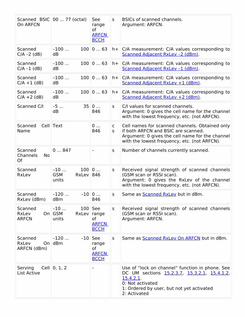
Scanned BSIC On ARFCN
00 ... 77 (octal) See range of ARFCN BCCH
s BSICs of scanned channels.Argument: ARFCN.
Scanned C/A –2 (dB)
–100 ... 100dB
0 ... 63 h+ C/A measurement: C/A values corresponding to Scanned Adjacent RxLev –2 (dBm).
Scanned C/A –1 (dB)
–100 ... 100dB
0 ... 63 h+ C/A measurement: C/A values corresponding to Scanned Adjacent RxLev –1 (dBm).
Scanned C/A +1 (dB)
–100 ... 100dB
0 ... 63 h+ C/A measurement: C/A values corresponding to Scanned Adjacent RxLev +1 (dBm).
Scanned C/A +2 (dB)
–100 ... 100dB
0 ... 63 h+ C/A measurement: C/A values corresponding to Scanned Adjacent RxLev +2 (dBm).
Scanned C/I –5 ... 35dB
0 ... 846
s C/I values for scanned channels.Argument: 0 gives the cell name for the channel with the lowest frequency, etc. (not ARFCN).
Scanned Cell Name
Text 0 ... 846
cs
Cell names for scanned channels. Obtained only if both ARFCN and BSIC are scanned.Argument: 0 gives the cell name for the channel with the lowest frequency, etc. (not ARFCN).
Scanned Channels No Of
0 ... 847 – s Number of channels currently scanned.
Scanned RxLev
–10 ... 100GSM RxLev units
0 ... 846
s Received signal strength of scanned channels (GSM scan or RSSI scan).Argument: 0 gives the RxLev of the channel with the lowest frequency, etc. (not ARFCN).
Scanned RxLev (dBm)
–120 ... –10dBm
0 ... 846
s Same as Scanned RxLev but in dBm.
Scanned RxLev On ARFCN
–10 ... 100GSM RxLev units
See range of ARFCN BCCH
s Received signal strength of scanned channels (GSM scan or RSSI scan).Argument: ARFCN.
Scanned RxLev On ARFCN (dBm)
–120 ... –10dBm
See range of ARFCN BCCH
s Same as Scanned RxLev On ARFCN but in dBm.
Serving Cell List Active
0, 1, 2 – Use of “lock on channel” function in phone. See DC UM sections 15.2.3.7, 15.3.2.1, 15.4.1.2, 15.4.2.1.0: Not activated1: Ordered by user, but not yet activated2: Activated

Signal Strength Hopping List
–120 ... –10dBm
0 ... 63 h+ Signal strength of each channel in the hopping list. This element thus gives more information than RxLev, which is an average over all channels in the hopping list.Argument: 0 means the first channel in the hopping list, etc.
Signal Strength On BCCH Carrier
–120 ... –10dBm
– Signal strength on the current BCCH. Especially useful for obtaining a correct measure of the cell size when frequency hopping is used and power control is applied to the TCHs.The following steps are used to find a value for the element:1.
Neighbor list. If the BCCH frequency is in the neighbor list, report its signal strength.
2.
Hopping list. If the BCCH is used as hopping frequency (in dedicated mode), report its signal strength.
3.
Idle mode. If the phone is in idle mode, report RxLev (dBm).
If frequency hopping is not used, step 2 becomes “If BCCH = TCH ...”.Invalid if no value is found in any of the above steps.
SNDCP BLER DL (%)
0 ... 100%
– g Percentage of SNDCP data blocks erroneously decoded on downlink.
SNDCP BLER UL (%)
0 ... 100%
– g Percentage of SNDCP data blocks resent on uplink.
SNDCP Bytes Received DL
0 ... 2 · 109bytes
– g Number of bytes received at the SNDCP protocol level since GPRS attach.
SNDCP Bytes Sent UL
0 ... 2 · 109bytes
– g Number of bytes sent at the SNDCP protocol level since GPRS attach.
SNDCP Throughput DL (kbit/s)
0 ... 400kbit/s
– g Data throughput (including protocol headers, but excluding retransmissions) on downlink at SNDCP protocol level.
SNDCP Throughput UL (kbit/s)
0 ... 400kbit/s
– g Data throughput (including protocol headers, but excluding retransmissions) on uplink at SNDCP protocol level.
Speech Codec Text – Currently used speech codec, e.g. “EFR”.
Speech Path Delay
0 ... 800ms
– AQM: The length of time it takes for the speech to travel from the Call Generator to the MTU and back to the Call Generator again.This element only appears in merged logfiles (see RA UM section 17.2).
Speed (km/h) 0 ... 250km/h
– p Speed in km/h.
Speed (mph) 0 ... 155 – p Speed in mph.

mph
SQI –20 ... 30dBQ
– g– Speech Quality Index. See DC UM chapter 28. The range depends on the speech codec used:HR (Half Rate): –20 ... 17 dBQFR (Full Rate): –19 ... 22 dBQEFR (Enhanced Full Rate): –20 ... 30 dBQAMR: Dependent on codec mode. The maximum SQI values are as follows:12.2 kbit/s: 30 dBQ10.2 kbit/s: 28 dBQ7.95 kbit/s: 28 dBQ7.40 kbit/s: 27 dBQ6.70 kbit/s: 27 dBQ5.90 kbit/s: 24 dBQ5.15 kbit/s: 21 dBQ4.75 kbit/s: 19 dBQNon-existent for GPRS (no voice data in packets).
SQI MOS 1 ... 5MOS
– g– SQI expressed on the MOS scale. See DC UM chapter 28.
Strongest Scanned ARFCN
See ARFCN BCCH
0 ... 846
s ARFCNs of scanned channels sorted by decreasing signal strength.Argument: Except in the case of neighbor list scanning, 0 means the strongest channel of those currently scanned, etc. When neighbor list scanning is performed, all neighbors come first, and then all other channels follow, both channel sets being sorted internally by decreasing signal strength.
Strongest Scanned Band
450 ... 1900MHz
0 ... 846
s Frequency bands of scanned channels sorted by decreasing signal strength.Argument: See Strongest Scanned ARFCN.
Strongest Scanned BSIC
Text 0 ... 846
s BSICs of scanned channels sorted by decreasing signal strength.Argument: See Strongest Scanned ARFCN.
Strongest Scanned C/I
–5 ... 35dB
0 ... 846
s C/I for scanned channels sorted by decreasing signal strength.Argument: See Strongest Scanned ARFCN.
Strongest Scanned Cell Name
Text 0 ... 846
cs
Names of scanned channels sorted by decreasing signal strength.Obtained only if both ARFCN and BSIC are scanned.Argument: See Strongest Scanned ARFCN.
Strongest Scanned RxLev (dBm)
–120 ... –10dBm
0 ... 846
s Signal strength of scanned channels in descending order.Argument: See Strongest Scanned ARFCN.
Sub Channel Number
0 ... 7 – Number of subchannel used in SDCCH or TCH half-rate channel.

TA 0 ... 63See Description
– Timing Advance. Valid only in dedicated mode. For the significance of the parameter value, see 3GPP 45.010.
Target Handover
0, 1, 2 – Use of lock handover function in phone (handover restricted to a chosen set of cells; see DC UM section 15.2.3.9).0: Not activated1: Ordered by user, but not yet activated2: Activated
TD-SCDMA Neighbor Cell Parameter ID
0 ... 127 1 ... 32 Neighbor Cell Parameter Identity of TD-SCDMA cell measured by TD-SCDMA capable phone while in GSM mode.Argument: Neighbors sorted by signal strength in descending order.
TD-SCDMA Neighbor No Of
1 ... 32 – Number of TD-SCDMA neighbors measured in GSM mode.
TD-SCDMA Neighbor RSCP
–116 ... –25dBm
1 ... 32 Received signal code power of each TD-SCDMA neighbor measured in GSM mode.
TD-SCDMA Neighbor UARFCN
0 ... 16383(frequency band dependent)
1 ... 32 UARFCN of each TD-SCDMA neighbor measured in GSM mode.
TFI DL 0 ... 31 – g Temporary Flow Id on uplink. Used to identify a one-block flow.
TFI UL 0 ... 31 – g Temporary Flow Id on downlink. Used to identify a one-block flow.
Time Text – Current time in text format: HH:MM:SS.mm, where mm = decimal seconds.
Timeslot IEs: General remark
The argument, where present, represents a timeslot but is just a sequence number. That is, 0 represents the first used timeslot, 1 the second, etc.; the argument value does not equate to the corresponding timeslot index.
Timeslot 0 ... 7 – Timeslot used for current call. Valid only in dedicated mode.
Timeslot Channel Type DL
Text 0 ... 7 ghs
Type of channel in each timeslot on downlink. See Channel Type.
Timeslot Channel Type UL
Text 0 ... 7 ghs
Type of channel in each timeslot on uplink. See Channel Type.
Timeslot Used DL
Text 0 ... 7 ghs
Timeslots used on downlink.
Timeslot Used Text 0 ... 7 g Timeslots used on uplink.
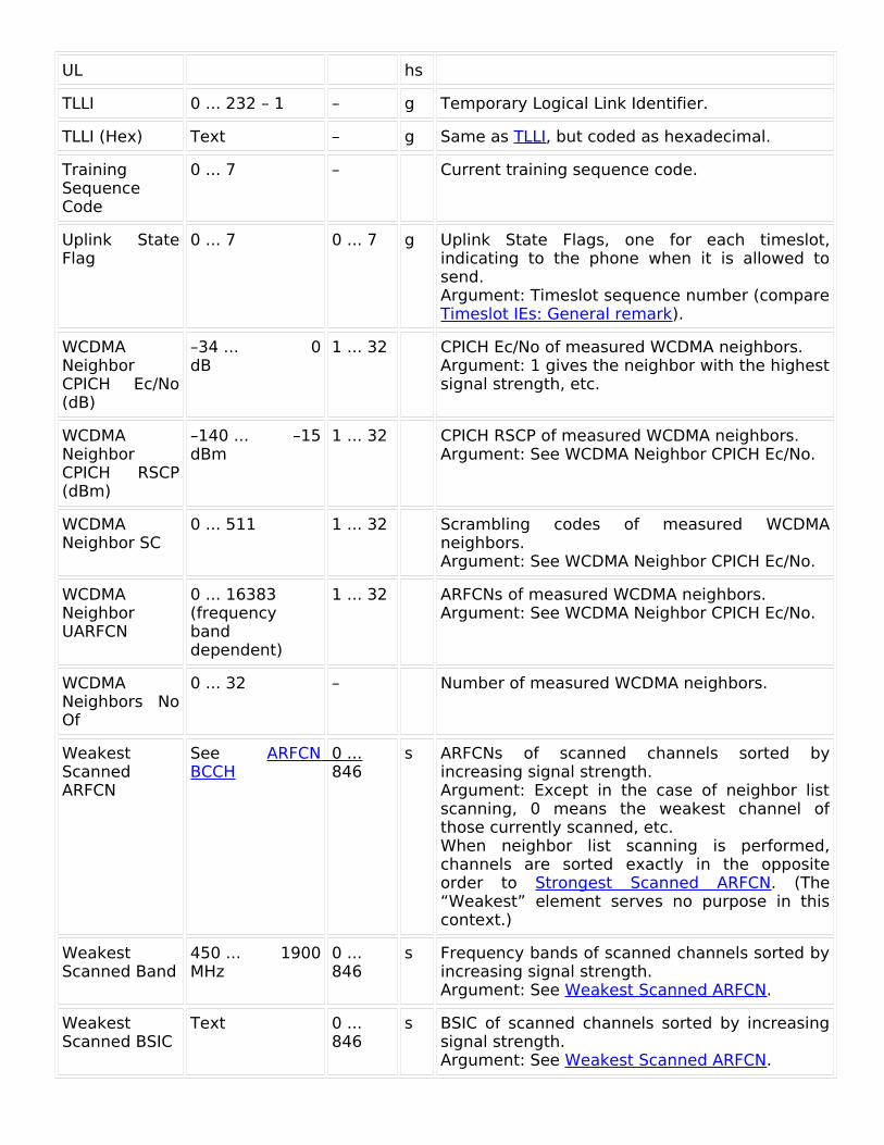
UL hs
TLLI 0 ... 232 – 1 – g Temporary Logical Link Identifier.
TLLI (Hex) Text – g Same as TLLI, but coded as hexadecimal.
Training Sequence Code
0 ... 7 – Current training sequence code.
Uplink State Flag
0 ... 7 0 ... 7 g Uplink State Flags, one for each timeslot, indicating to the phone when it is allowed to send.Argument: Timeslot sequence number (compare Timeslot IEs: General remark).
WCDMA Neighbor CPICH Ec/No (dB)
–34 ... 0dB
1 ... 32 CPICH Ec/No of measured WCDMA neighbors.Argument: 1 gives the neighbor with the highest signal strength, etc.
WCDMA Neighbor CPICH RSCP (dBm)
–140 ... –15dBm
1 ... 32 CPICH RSCP of measured WCDMA neighbors.Argument: See WCDMA Neighbor CPICH Ec/No.
WCDMA Neighbor SC
0 ... 511 1 ... 32 Scrambling codes of measured WCDMA neighbors.Argument: See WCDMA Neighbor CPICH Ec/No.
WCDMA Neighbor UARFCN
0 ... 16383(frequency band dependent)
1 ... 32 ARFCNs of measured WCDMA neighbors.Argument: See WCDMA Neighbor CPICH Ec/No.
WCDMA Neighbors No Of
0 ... 32 – Number of measured WCDMA neighbors.
Weakest Scanned ARFCN
See ARFCN BCCH
0 ... 846
s ARFCNs of scanned channels sorted by increasing signal strength.Argument: Except in the case of neighbor list scanning, 0 means the weakest channel of those currently scanned, etc.When neighbor list scanning is performed, channels are sorted exactly in the opposite order to Strongest Scanned ARFCN. (The “Weakest” element serves no purpose in this context.)
Weakest Scanned Band
450 ... 1900MHz
0 ... 846
s Frequency bands of scanned channels sorted by increasing signal strength.Argument: See Weakest Scanned ARFCN.
Weakest Scanned BSIC
Text 0 ... 846
s BSIC of scanned channels sorted by increasing signal strength.Argument: See Weakest Scanned ARFCN.

Weakest Scanned C/I
–5 ... 35dB
0 ... 846
s C/I for scanned channels sorted by increasing signal strength.Argument: See Weakest Scanned ARFCN.
Weakest Scanned Cell Name
Text 0 ... 846
cs
Names of scanned channels sorted by increasing signal strength.Obtained only if both ARFCN and BSIC are scanned.Argument: See Weakest Scanned ARFCN.
Weakest Scanned RxLev (dBm)
–120 ... –10dBm
0 ... 846
s Signal strength of scanned channels in ascending order.Argument: See Weakest Scanned ARFCN.