gs2k module power measurement application note · 2018-02-07 · gs2k module power measurement...
TRANSCRIPT

GS2K Module Power Measurement Application Note
80560NT11603A Rev. 1.0 – 2016-11-01

GS2K Module Power Measurement Application Note
80560NT11603A Rev. 1.0 Page 2 of 46 2016-11-01
NOTICE
COPYRIGHTS
COMPUTER SOFTWARE COPYRIGHTS
SPECIFICATIONS ARE SUBJECT TO CHANGE WITHOUT NOTICE
While reasonable efforts have been made to assure the accuracy of this document, Telit assumes no liability resulting from any inaccuracies or omissions in this document, or from use of the information obtained herein. The information in this document has been carefully checked and is believed to be reliable. However, no responsibility is assumed for inaccuracies or omissions. Telit reserves the right to make changes to any products described herein and reserves the right to revise this document and to make changes from time to time in content hereof with no obligation to notify any person of revisions or changes. Telit does not assume any liability arising out of the application or use of any product, software, or circuit described herein; neither does it convey license under its patent rights or the rights of others.
It is possible that this publication may contain references to, or information about Telit products (machines and programs), programming, or services that are not announced in your country. Such references or information must not be construed to mean that Telit intends to announce such Telit products, programming, or services in your country.
This instruction manual and the Telit products described in this instruction manual may be, include or describe copyrighted Telit material, such as computer programs stored in semiconductor memories or other media. Laws in the Italy and other countries preserve for Telit and its licensors certain exclusive rights for copyrighted material, including the exclusive right to copy, reproduce in any form, distribute and make derivative works of the copyrighted material. Accordingly, any copyrighted material of Telit and its licensors contained herein or in the Telit products described in this instruction manual may not be copied, reproduced, distributed, merged or modified in any manner without the express written permission of Telit. Furthermore, the purchase of Telit products shall not be deemed to grant either directly or by implication, estoppel, or otherwise, any license under the copyrights, patents or patent applications of Telit, as arises by operation of law in the sale of a product.
The Telit and 3rd Party supplied Software (SW) products described in this instruction manual may include copyrighted Telit and other 3rd Party supplied computer programs stored in semiconductor memories or other media. Laws in the Italy and other countries preserve for Telit and other 3rd Party supplied SW certain exclusive rights for copyrighted computer programs, including the exclusive right to copy or reproduce in any form the copyrighted computer program. Accordingly, any copyrighted Telit or other 3rd Party supplied SW computer programs contained in the Telit products described in this instruction manual may not be copied (reverse engineered) or reproduced in any manner without the express written permission of Telit or the 3rd Party SW supplier. Furthermore, the purchase of Telit products shall not be deemed to grant either directly or by implication, estoppel, or otherwise, any license under the copyrights, patents or patent applications of Telit or other 3rd Party supplied SW, except for the normal non-exclusive, royalty free license to use that arises by operation of law in the sale of a product.

GS2K Module Power Measurement Application Note
80560NT11603A Rev. 1.0 Page 3 of 46 2016-11-01
USAGE AND DISCLOSURE RESTRICTIONS
I. License Agreements
II. Copyrighted Materials
III. High Risk Materials
IV. Trademarks
V. Third Party Rights
The software described in this document is the property of Telit and its licensors. It is furnished by express license agreement only and may be used only in accordance with the terms of such an agreement.
Software and documentation are copyrighted materials. Making unauthorized copies is prohibited by law. No part of the software or documentation may be reproduced, transmitted, transcribed, stored in a retrieval system, or translated into any language or computer language, in any form or by any means, without prior written permission of Telit
Components, units, or third-party products used in the product described herein are NOT fault-tolerant and are NOT designed, manufactured, or intended for use as on-line control equipment in the following hazardous environments requiring fail-safe controls: the operation of Nuclear Facilities, Aircraft Navigation or Aircraft Communication Systems, Air Traffic Control, Life Support, or Weapons Systems (High Risk Activities"). Telit and its supplier(s) specifically disclaim any expressed or implied warranty of fitness for such High Risk Activities.
TELIT and the Stylized T Logo are registered in Trademark Office. All other product or service names are the property of their respective owners.
The software may include Third Party Right software. In this case you agree to comply with all terms and conditions imposed on you in respect of such separate software. In addition to Third Party Terms, the disclaimer of warranty and limitation of liability provisions in this License shall apply to the Third Party Right software.
TELIT HEREBY DISCLAIMS ANY AND ALL WARRANTIES EXPRESS OR IMPLIED FROM ANY THIRD PARTIES REGARDING ANY SEPARATE FILES, ANY THIRD PARTY MATERIALS INCLUDED IN THE SOFTWARE, ANY THIRD PARTY MATERIALS FROM WHICH THE SOFTWARE IS DERIVED (COLLECTIVELY “OTHER CODE”), AND THE USE OF ANY OR ALL THE OTHER CODE IN CONNECTION WITH THE SOFTWARE, INCLUDING (WITHOUT LIMITATION) ANY WARRANTIES OF SATISFACTORY QUALITY OR FITNESS FOR A PARTICULAR PURPOSE.
NO THIRD PARTY LICENSORS OF OTHER CODE SHALL HAVE ANY LIABILITY FOR ANY DIRECT, INDIRECT, INCIDENTAL, SPECIAL, EXEMPLARY, OR CONSEQUENTIAL DAMAGES (INCLUDING WITHOUT LIMITATION LOST PROFITS), HOWEVER CAUSED AND WHETHER MADE UNDER CONTRACT, TORT OR OTHER LEGAL THEORY, ARISING IN ANY WAY OUT OF THE USE OR DISTRIBUTION OF THE OTHER CODE OR THE EXERCISE OF ANY RIGHTS GRANTED UNDER EITHER OR BOTH THIS LICENSE AND THE LEGAL TERMS APPLICABLE TO ANY SEPARATE FILES, EVEN IF ADVISED OF THE POSSIBILITY OF SUCH DAMAGES.

GS2K Module Power Measurement Application Note
80560NT11603A Rev. 1.0 Page 4 of 46 2016-11-01
APPLICABILITY TABLE
Note: The features described in the present document are provided by the products equipped with the software versions equal or higher than the versions shown in the table. See also the Document History chapter.
PRODUCT
GS2K based Modules
For EVB /SKB

GS2K Module Power Measurement Application Note
80560NT11603A Rev. 1.0 Page 5 of 46 2016-11-01
Revision History
Version Date Remarks
1.0 November 2016 Initial release

GS2K Module Power Measurement Application Note
80560NT11603A Rev. 1.0 Page 6 of 46 2016-11-01
Table of Contents NOTICE……………….. ................................................................................................................ 2
COPYRIGHTS…… ...................................................................................................................... 2
COMPUTER SOFTWARE COPYRIGHTS .................................................................................. 2
USAGE AND DISCLOSURE RESTRICTIONS ........................................................................... 3
APPLICABILITY TABLE ............................................................................................................. 4
CHAPTER 1 INTRODUCTION .................................................................................................... 9
1.1 PURPOSE .........................................................................................................................9 CHAPTER 2 POWER MANAGEMENT STATES FOR EVB3.0 ............................................... 10
1.2 MEASURING STANDBY POWER ........................................................................................10 1.3 MEASURING DEEP SLEEP POWER ...................................................................................17 1.4 MEASURING OPERATING POWER ....................................................................................24
CHAPTER 3 POWER MANAGEMENT STATES FOR SKB .................................................... 30
1.5 POWER MEASUREMENT CIRCUITRY .................................................................................30 1.6 BATTERY GAUGE CIRCUIT ...............................................................................................31 1.7 SKB POWER STATES AND AVERAGE CURRENT ...............................................................31 1.8 CONFIGURING THE SKB FOR CURRENT MEASUREMENT ..................................................32
Building the S2W Firmware using SDK Builder .................................................................. 32 Programming the S2W Firmware into the SKB ................................................................... 32 Jumper Settings for Current Measurements ....................................................................... 32 Connecting the Bench Supply and Digital Multi-Meter ....................................................... 33 Configuring the Serial Port .................................................................................................. 33
1.9 MEASURING TRANSMIT CURRENT ...................................................................................34 1.10 MEASURING RECEIVE CURRENT .....................................................................................34 1.11 MEASURING DEEPSLEEP CURRENT ................................................................................35 1.12 MEASURING STANDBY CURRENT .....................................................................................35 1.13 MEASURING PS-POLL AVERAGE CURRENT ....................................................................36
PS-POLL with Standby Average Current Measurements ................................................... 36 PS-POLL with DeepSleep Average Current Measurements .............................................. 38
APPENDIX A BUILDING THE S2W FIRMWARE USING SDK BUILDER ............................. 40
APPENDIX B PROGRAMMING SKB WITH GAINSPAN FIRMWARE ................................... 42
APPENDIX C CONFIGURING SERIAL PORT FOR POWER MEASUREMENT ................... 44

GS2K Module Power Measurement Application Note
80560NT11603A Rev. 1.0 Page 7 of 46 2016-11-01
List of Figures
Figure 1: Experimental Setup for Measuring GS2200 EVB3 REV 1.0 Board Standby Power .11
Figure 2: Tera Term VT COM Port Settings - Standby Mode ....................................................14
Figure 3: Serial-to-WiFI APP Message Within Tera Term Window - Standby Mode ................15
Figure 4: Setting Standby Mode in Milliseconds – Standby Mode ............................................16
Figure 5: Evaluation Board 3.0 Bank of Resistors - Measuring Deep Sleep Power .................17
Figure 6: Experimental Setup for Measuring GS2011 REV 3.0 Board Deep Sleep Power ......18
Figure 7: Tera Term VT COM Port Settings – Standby Mode ...................................................21
Figure 8: Serial-to-WiFi APP Message Within Tera Term Window - Standby Mode ................22
Figure 9: Setting Module into Deep Sleep Mode .......................................................................23
Figure 10: Experimental Setup for Measuring EVB3.0 Board Operating Power .......................24
Figure 11: GS2200MIZ Associated to AP in PS-Poll Mode with DTIM=1 .................................29
Figure 12:Power Measurement Circuit ......................................................................................30
Figure 13: Power Measurement Mode Switch ...........................................................................31
Figure 14: Battery Gauge Circuit ................................................................................................31
Figure 15: Current Profile in using PS-Polling with Standy between Beacons .........................38
Figure 16: Current Profile using PS-Polling with Deepsleep between Beacons .......................39
Figure 17: SDK Builder Configuration ........................................................................................40
Figure 18: SDK Builder Configuration ........................................................................................40
Figure 19: SDK Builder Configuration ........................................................................................41
Figure 20: Program Mode and GainSpan Flash Programmer ...................................................42
Figure 21: Status of Firmware Programming .............................................................................43
Figure 22: Serial Port Settings ...................................................................................................44
Figure 23: Serial Port Output .....................................................................................................45

GS2K Module Power Measurement Application Note
80560NT11603A Rev. 1.0 Page 8 of 46 2016-11-01
List of Tables Table 1: Standby Mode Jumper Settings for EVB3.0 ................................................................12
Table 2: Standby Mode Jumper Settings for EVB3.0 ................................................................19
Table 3: Operating Power Measurement Jumper Settings for EVB3.0 .....................................26
Table 4: Power States ................................................................................................................32
Table 5: Recommended Jumper Settings for Power Measurements ........................................32
Table 6: Power Source Selection ...............................................................................................33
Table 7: AT Commands and Comments ....................................................................................34
GS2K Module Power Measurement Application Note
80560NT11603A Rev. 1.0 Page 9 of 46 2016-11-01
Chapter 1 Introduction
1.1 PURPOSE
This document describes a method for measuring the typical power consumption of a Sensor Node based on the GainSpan System-on-Chip (SoC), currently exemplified by the GS2000. All measurements described by this document can be performed with the GainSpan GS2011 Evaluation Boards (EVB) of the GS2011M EVB3 – REV2.0 (noted by “GS2xxxM EVB3 – REV2.0” marking on PCB of evaluation board and a GS2011MIE, GS2011MIZ, or GS2011MIES and GS2200MIZ EVB3-REV1_0 marking on the label on the shield of the GainSpan module on the board). These boards are GainSpan SoC reference designs that can be powered by either a lab power supply or a standard USB power supply. They include all the peripheral circuitry required to power and clock the SoC, as well as on-board light and temperature sensors.
Using any of the above evaluation boards and the Serial-to-Wi-Fi reference firmware applications as described by this document simplifies measurement of both Standby, Deep Sleep, and Operating power consumption.
NOTE: The power measurement instructions in this document is based on the GS2200M EVB3.0.

GS2K Module Power Measurement Application Note
80560NT11603A Rev. 1.0 Page 10 of 46 2016-11-01
Chapter 2 Power Management States for EVB3.0
The power consumption of the EVB boards is dominated by the GainSpan SoC itself. The power consumed by the SoC depends on the operations of its various system components. Note that the SoC Standby and Deep Sleep states are distinguished from other states by the deactivation of the high-speed 40 MHz crystal and 80 MHz RC oscillators, which both saves power in the clock oscillator and terminates high-speed switching in the remainder of the chip. In the Standby state, only the low-frequency (32.768 kHz) RTC module and associated circuitry are operating, and power consumption is greatly reduced.
Power consumption is computed by multiplying measured voltage and power. Power consumption is typically measured by placing a small power measuring resistor in series with the power supply. This resistor must be scaled appropriately to provide enough gain to measure the power with sufficient accuracy, while at the same time, not dropping enough voltage to affect the experiment. The power consumption of the GainSpan GS2200 SoC varies over 5 orders of magnitude (from 4 μA to 300 mA) since different methods are being used for measuring Standby, Deep Sleep, and operating power. The methods to be used for performing measurements of each of these power draws are provided by the following sections of this document.
1.2 MEASURING STANDBY POWER
The following procedure to measure standby power can be used with the GS2011module as shield marking with GS2011M EVB3 boards and GS2200MIZ modules on GS2200M EVB3 marking on PCB of evaluation board. Also, GS2011MIE, GS2011MIZ or GS2011MIES marking on the label on the shield of the GainSpan module on the board.
To measure standby power, a 3.3 Volt DC power supply is connected to test points TP3 (+) and TP6 (GND) of the EVB3.0 board (TP3 is a yellow loop connector labeled “BENCH 3V3”, while TP6 is a brown loop connector labeled “POWER MEAS SUPPLY GND) and an ammeter is connected to the two pins of J23 (after removing the jumper from this connector). The GS2200 module under test is then placed into standby mode. The ammeter measures the power drawn through the VRTC supply in the GainSpan module which supplies the RTC (Real Time Clock) block which is the only part of the module in operation while the module is in standby mode.
The connections to be done on the GS2200 EVB 3 REV 3.0 board are as shown in Figure 1.
GS2K Module Power Measurement Application Note
80560NT11603A Rev. 1.0 Page 11 of 46 2016-11-01
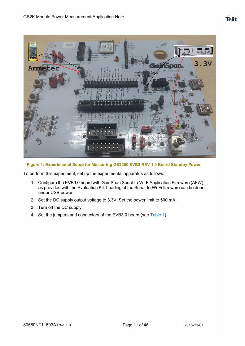
Figure 1: Experimental Setup for Measuring GS2200 EVB3 REV 1.0 Board Standby Power
To perform this experiment, set up the experimental apparatus as follows:
1. Configure the EVB3.0 board with GainSpan Serial-to-Wi-F Application Firmware (AFW), as provided with the Evaluation Kit. Loading of the Serial-to-Wi-Fi firmware can be done under USB power.
2. Set the DC supply output voltage to 3.3V. Set the power limit to 500 mA.
3. Turn off the DC supply.
4. Set the jumpers and connectors of the EVB3.0 board (see Table 1).

GS2K Module Power Measurement Application Note
80560NT11603A Rev. 1.0 Page 12 of 46 2016-11-01
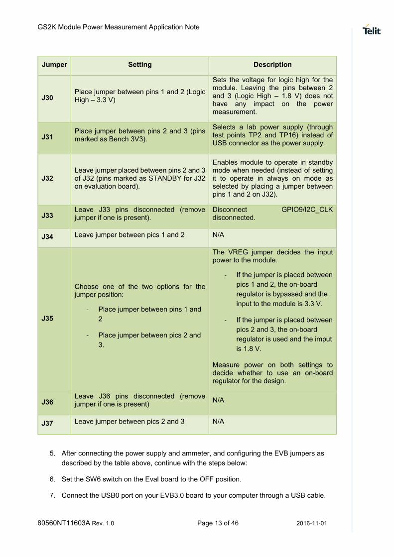
Table 1: Standby Mode Jumper Settings for EVB3.0
Jumper Setting Description
J1 Leave all pins of J1 disconnected (do not place any jumpers on J1)
N/A
J2 Leave all pins of J2 disconnected (do not place any jumpers on J2)
N/A
J4
Leave all jumpers connected for J4 with the exception of the following two jumpers:
- Remove the jumper placed
between pins 1 and 2 (far left of J4
labeled V_LED)
- Remove the jumper placed
between pins 37 and 38 (second
jumper from right to left of J4
labeled VFLASH)
- Remove the jumper placed
between pins 11 and 12 (labeled
VIN_3V3_LED)
- Removes the jumper placed
between pins 13 and 14 (labeled
3V3_LED)
- Remove the jumper placed
between pins 39 and 40 (labeled
SEN_PWR)
- Removing the V_LED jumper
will remove power from the
EVB board’s LEDs.
- Removing the VFLASH jumper
will remove power from the
EVB board’s flash memory as
well as from the apple
authentication chip (the second
is only valid for EVB boards
that include this chip).
- Removing the VIN_3V3_LED
and 3V3_LED jumper
disconnects LEDs D8 and D9.
- Removing the SEN_PWR
jumper disconnects the power
to the sensors.
J13 Leave jumper in place between pins 1 and 2 for J13 at start of test.
Leaves GPIO25/UART0_RTS connected .
J14 Leave jumper in place between pins 1 and 2 for J14 at start of test.
Shorts 1 Ohm resistor used to measure active mode power consumption.
J15 Leave jumper in place between pins 1 and 2 for J15 at start of test.
Shorts 100 Ohm resistor used to measure deep sleep power consumption.
J23
Connect leftmost pin of J23 to GND terminal of ammeter and rightmost pin of J23 to + terminal of ammeter.
Connects Ammeter in line between 3V3 and GS2011 VRTC power supply pin for standby power measurement
J24 Leave J24 pins disconnected (remove jumper if one is present).
Leaves GPIO25 Program select input in Disconnects GPIO8/I2C_DATA
J29 Leave jumper between pins 1 and 2 (closer to module on evaluation board).
N/A
GS2K Module Power Measurement Application Note
80560NT11603A Rev. 1.0 Page 13 of 46 2016-11-01
Jumper Setting Description
J30 Place jumper between pins 1 and 2 (Logic High – 3.3 V)
Sets the voltage for logic high for the module. Leaving the pins between 2 and 3 (Logic High – 1.8 V) does not have any impact on the power measurement.
J31 Place jumper between pins 2 and 3 (pins marked as Bench 3V3).
Selects a lab power supply (through test points TP2 and TP16) instead of USB connector as the power supply.
J32 Leave jumper placed between pins 2 and 3 of J32 (pins marked as STANDBY for J32 on evaluation board).
Enables module to operate in standby mode when needed (instead of setting it to operate in always on mode as selected by placing a jumper between pins 1 and 2 on J32).
J33 Leave J33 pins disconnected (remove jumper if one is present).
Disconnect GPIO9/I2C_CLK disconnected.
J34 Leave jumper between pics 1 and 2 N/A
J35
Choose one of the two options for the jumper position:
- Place jumper between pins 1 and
2
- Place jumper between pics 2 and
3.
The VREG jumper decides the input power to the module.
- If the jumper is placed between
pics 1 and 2, the on-board
regulator is bypassed and the
input to the module is 3.3 V.
- If the jumper is placed between
pics 2 and 3, the on-board
regulator is used and the imput
is 1.8 V.
Measure power on both settings to decide whether to use an on-board regulator for the design.
J36 Leave J36 pins disconnected (remove jumper if one is present)
N/A
J37 Leave jumper between pics 2 and 3 N/A
5. After connecting the power supply and ammeter, and configuring the EVB jumpers as
described by the table above, continue with the steps below:
6. Set the SW6 switch on the Eval board to the OFF position.
7. Connect the USB0 port on your EVB3.0 board to your computer through a USB cable.
GS2K Module Power Measurement Application Note
80560NT11603A Rev. 1.0 Page 14 of 46 2016-11-01
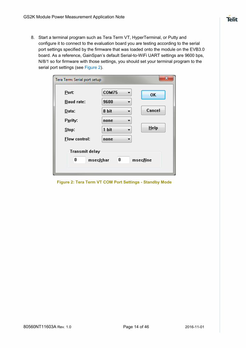
8. Start a terminal program such as Tera Term VT, HyperTerminal, or Putty and
configure it to connect to the evaluation board you are testing according to the serial
port settings specified by the firmware that was loaded onto the module on the EVB3.0
board. As a reference, GainSpan’s default Serial-to-WiFi UART settings are 9600 bps,
N/8/1 so for firmware with those settings, you should set your terminal program to the
serial port settings (see Figure 2).
Figure 2: Tera Term VT COM Port Settings - Standby Mode
GS2K Module Power Measurement Application Note
80560NT11603A Rev. 1.0 Page 15 of 46 2016-11-01
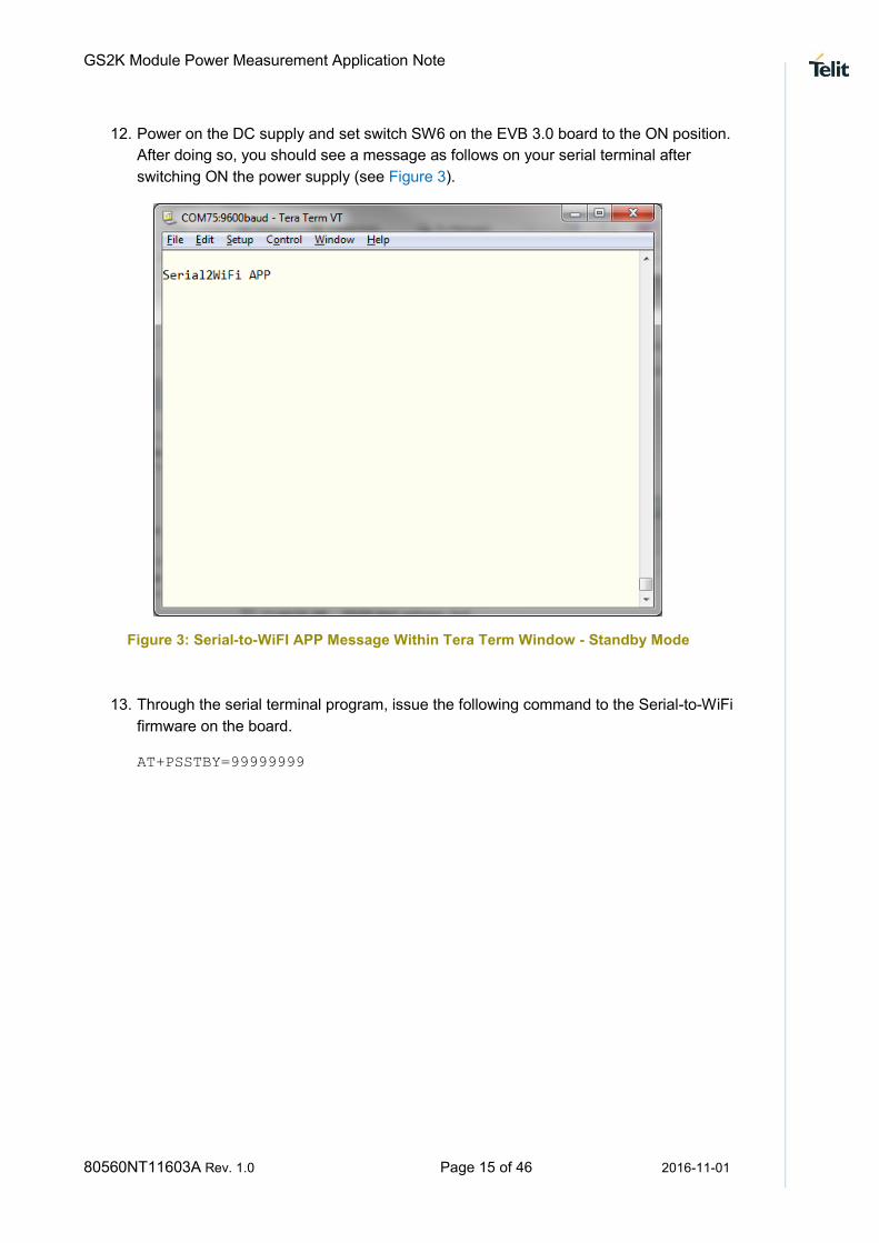
12. Power on the DC supply and set switch SW6 on the EVB 3.0 board to the ON position.
After doing so, you should see a message as follows on your serial terminal after
switching ON the power supply (see Figure 3).
Figure 3: Serial-to-WiFI APP Message Within Tera Term Window - Standby Mode
13. Through the serial terminal program, issue the following command to the Serial-to-WiFi
firmware on the board.
AT+PSSTBY=99999999

GS2K Module Power Measurement Application Note
80560NT11603A Rev. 1.0 Page 16 of 46 2016-11-01
This will set the board into standby mode for a period of 99,999,999 milliseconds, which will provide more than enough time for a voltmeter measurement to be completed. You can see this command being issued (see Figure 4).
Figure 4: Setting Standby Mode in Milliseconds – Standby Mode
14. Once the above command has been issued, and while the board is still in standby
mode (the message “Out of StandBy-Timer” is not received from the board on the
serial terminal) measure the observed power on the ammeter. This power will be the
module’s standby power.
Measured standby power consumption for a GS2200MIZ 3.3 module EVB3.0 board running standard 5.3.0 release candidate firmware (obtained from GainSpan’s website SDK Builder tool) when powered from a 3.3V DC supply was ~8 μA.
GS2K Module Power Measurement Application Note
80560NT11603A Rev. 1.0 Page 17 of 46 2016-11-01
1.3 MEASURING DEEP SLEEP POWER
The following procedure to measure deep sleep power can be used with the GS2200 EVB3 boards with GS2200M-EVB3 REV 1.1 marking on PCB and a GS2200MIZ marking on the label on the shield of the GainSpan module on the board.
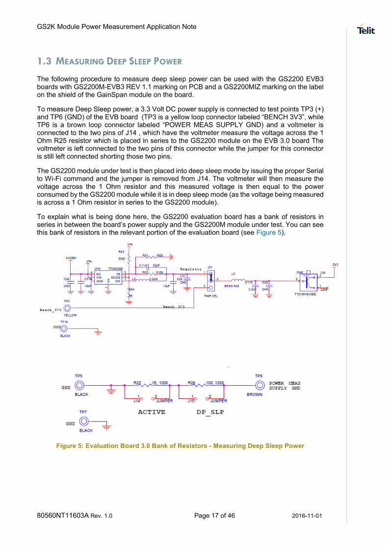
To measure Deep Sleep power, a 3.3 Volt DC power supply is connected to test points TP3 (+) and TP6 (GND) of the EVB board (TP3 is a yellow loop connector labeled “BENCH 3V3”, while TP6 is a brown loop connector labeled “POWER MEAS SUPPLY GND) and a voltmeter is connected to the two pins of J14 , which have the voltmeter measure the voltage across the 1 Ohm R25 resistor which is placed in series to the GS2200 module on the EVB 3.0 board The voltmeter is left connected to the two pins of this connector while the jumper for this connector is still left connected shorting those two pins.
The GS2200 module under test is then placed into deep sleep mode by issuing the proper Serial to Wi-Fi command and the jumper is removed from J14. The voltmeter will then measure the voltage across the 1 Ohm resistor and this measured voltage is then equal to the power consumed by the GS2200 module while it is in deep sleep mode (as the voltage being measured is across a 1 Ohm resistor in series to the GS2200 module).
To explain what is being done here, the GS2200 evaluation board has a bank of resistors in series in between the board’s power supply and the GS2200M module under test. You can see this bank of resistors in the relevant portion of the evaluation board (see Figure 5).
Figure 5: Evaluation Board 3.0 Bank of Resistors - Measuring Deep Sleep Power

GS2K Module Power Measurement Application Note
80560NT11603A Rev. 1.0 Page 18 of 46 2016-11-01
The connections to be done on the GS2200 EVB 3 REV 3.0 board as shown in Figure 6.
Figure 6: Experimental Setup for Measuring GS2011 REV 3.0 Board Deep Sleep Power
To perform this experiment, set up the experimental apparatus as follows:
1. Configure the EVB3.0 Board with GainSpan Serial-to-Wi-Fi Application Firmware (AFW), as provided with the Evaluation Kit. Loading of the Serial-to-Wi-Fi firmware can be done under USB power.
2. Set the DC supply output voltage to 3.3V. Set the power limit to 500 mA.
3. Turn off the DC supply.
4. Set the jumpers and connectors of the EVB3.0 board (see Table 2).
GS2K Module Power Measurement Application Note
80560NT11603A Rev. 1.0 Page 19 of 46 2016-11-01
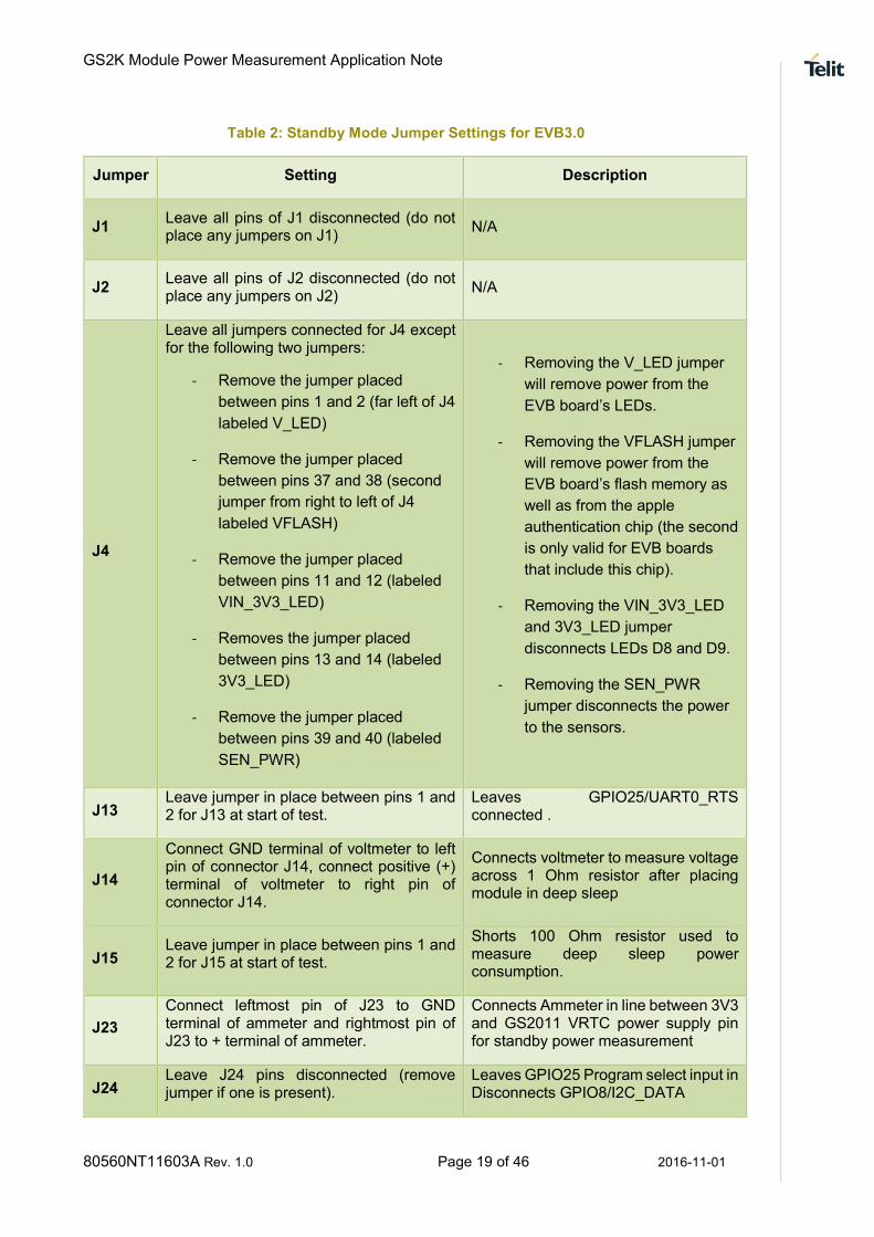
Table 2: Standby Mode Jumper Settings for EVB3.0
Jumper Setting Description
J1 Leave all pins of J1 disconnected (do not place any jumpers on J1)
N/A
J2 Leave all pins of J2 disconnected (do not place any jumpers on J2)
N/A
J4
Leave all jumpers connected for J4 except for the following two jumpers:
- Remove the jumper placed
between pins 1 and 2 (far left of J4
labeled V_LED)
- Remove the jumper placed
between pins 37 and 38 (second
jumper from right to left of J4
labeled VFLASH)
- Remove the jumper placed
between pins 11 and 12 (labeled
VIN_3V3_LED)
- Removes the jumper placed
between pins 13 and 14 (labeled
3V3_LED)
- Remove the jumper placed
between pins 39 and 40 (labeled
SEN_PWR)
- Removing the V_LED jumper
will remove power from the
EVB board’s LEDs.
- Removing the VFLASH jumper
will remove power from the
EVB board’s flash memory as
well as from the apple
authentication chip (the second
is only valid for EVB boards
that include this chip).
- Removing the VIN_3V3_LED
and 3V3_LED jumper
disconnects LEDs D8 and D9.
- Removing the SEN_PWR
jumper disconnects the power
to the sensors.
J13 Leave jumper in place between pins 1 and 2 for J13 at start of test.
Leaves GPIO25/UART0_RTS connected .
J14
Connect GND terminal of voltmeter to left pin of connector J14, connect positive (+) terminal of voltmeter to right pin of connector J14.
Connects voltmeter to measure voltage across 1 Ohm resistor after placing module in deep sleep
J15 Leave jumper in place between pins 1 and 2 for J15 at start of test.
Shorts 100 Ohm resistor used to measure deep sleep power consumption.
J23
Connect leftmost pin of J23 to GND terminal of ammeter and rightmost pin of J23 to + terminal of ammeter.
Connects Ammeter in line between 3V3 and GS2011 VRTC power supply pin for standby power measurement
J24 Leave J24 pins disconnected (remove jumper if one is present).
Leaves GPIO25 Program select input in Disconnects GPIO8/I2C_DATA
GS2K Module Power Measurement Application Note
80560NT11603A Rev. 1.0 Page 20 of 46 2016-11-01
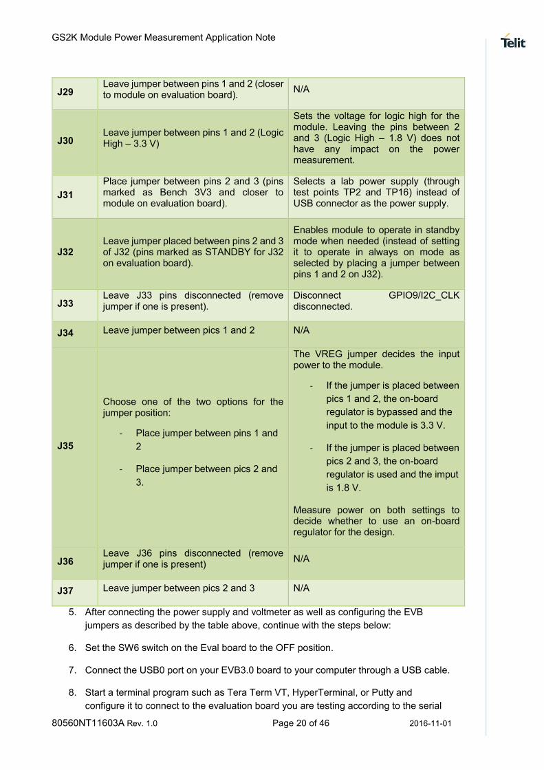
J29 Leave jumper between pins 1 and 2 (closer to module on evaluation board).
N/A
J30 Leave jumper between pins 1 and 2 (Logic High – 3.3 V)
Sets the voltage for logic high for the module. Leaving the pins between 2 and 3 (Logic High – 1.8 V) does not have any impact on the power measurement.
J31
Place jumper between pins 2 and 3 (pins marked as Bench 3V3 and closer to module on evaluation board).
Selects a lab power supply (through test points TP2 and TP16) instead of USB connector as the power supply.
J32 Leave jumper placed between pins 2 and 3 of J32 (pins marked as STANDBY for J32 on evaluation board).
Enables module to operate in standby mode when needed (instead of setting it to operate in always on mode as selected by placing a jumper between pins 1 and 2 on J32).
J33 Leave J33 pins disconnected (remove jumper if one is present).
Disconnect GPIO9/I2C_CLK disconnected.
J34 Leave jumper between pics 1 and 2 N/A
J35
Choose one of the two options for the jumper position:
- Place jumper between pins 1 and
2
- Place jumper between pics 2 and
3.
The VREG jumper decides the input power to the module.
- If the jumper is placed between
pics 1 and 2, the on-board
regulator is bypassed and the
input to the module is 3.3 V.
- If the jumper is placed between
pics 2 and 3, the on-board
regulator is used and the imput
is 1.8 V.
Measure power on both settings to decide whether to use an on-board regulator for the design.
J36 Leave J36 pins disconnected (remove jumper if one is present)
N/A
J37 Leave jumper between pics 2 and 3 N/A
5. After connecting the power supply and voltmeter as well as configuring the EVB
jumpers as described by the table above, continue with the steps below:
6. Set the SW6 switch on the Eval board to the OFF position.
7. Connect the USB0 port on your EVB3.0 board to your computer through a USB cable.
8. Start a terminal program such as Tera Term VT, HyperTerminal, or Putty and
configure it to connect to the evaluation board you are testing according to the serial
GS2K Module Power Measurement Application Note
80560NT11603A Rev. 1.0 Page 21 of 46 2016-11-01
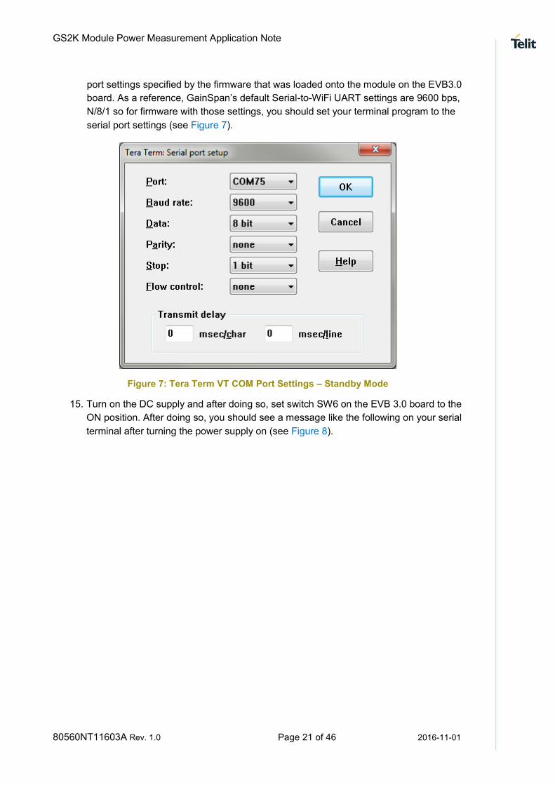
port settings specified by the firmware that was loaded onto the module on the EVB3.0
board. As a reference, GainSpan’s default Serial-to-WiFi UART settings are 9600 bps,
N/8/1 so for firmware with those settings, you should set your terminal program to the
serial port settings (see Figure 7).
Figure 7: Tera Term VT COM Port Settings – Standby Mode
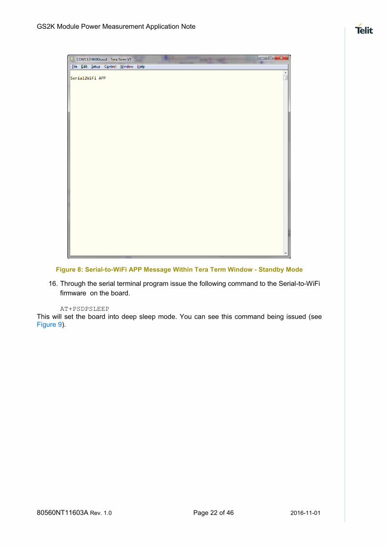
15. Turn on the DC supply and after doing so, set switch SW6 on the EVB 3.0 board to the
ON position. After doing so, you should see a message like the following on your serial
terminal after turning the power supply on (see Figure 8).
GS2K Module Power Measurement Application Note
80560NT11603A Rev. 1.0 Page 22 of 46 2016-11-01
Figure 8: Serial-to-WiFi APP Message Within Tera Term Window - Standby Mode
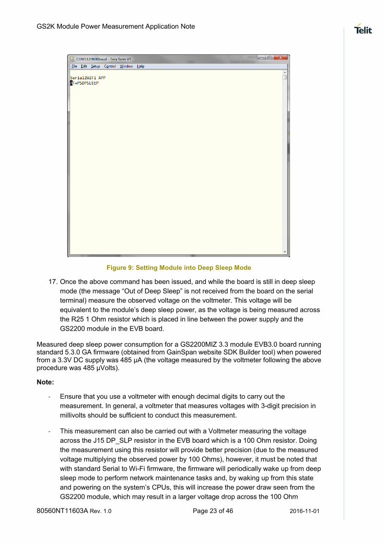
16. Through the serial terminal program issue the following command to the Serial-to-WiFi
firmware on the board.
AT+PSDPSLEEP
This will set the board into deep sleep mode. You can see this command being issued (see Figure 9).
GS2K Module Power Measurement Application Note
80560NT11603A Rev. 1.0 Page 23 of 46 2016-11-01
Figure 9: Setting Module into Deep Sleep Mode
17. Once the above command has been issued, and while the board is still in deep sleep
mode (the message “Out of Deep Sleep” is not received from the board on the serial
terminal) measure the observed voltage on the voltmeter. This voltage will be
equivalent to the module’s deep sleep power, as the voltage is being measured across
the R25 1 Ohm resistor which is placed in line between the power supply and the
GS2200 module in the EVB board.
Measured deep sleep power consumption for a GS2200MIZ 3.3 module EVB3.0 board running standard 5.3.0 GA firmware (obtained from GainSpan website SDK Builder tool) when powered from a 3.3V DC supply was 485 μA (the voltage measured by the voltmeter following the above procedure was 485 μVolts).
Note:
- Ensure that you use a voltmeter with enough decimal digits to carry out the
measurement. In general, a voltmeter that measures voltages with 3-digit precision in
millivolts should be sufficient to conduct this measurement.
- This measurement can also be carried out with a Voltmeter measuring the voltage
across the J15 DP_SLP resistor in the EVB board which is a 100 Ohm resistor. Doing
the measurement using this resistor will provide better precision (due to the measured
voltage multiplying the observed power by 100 Ohms), however, it must be noted that
with standard Serial to Wi-Fi firmware, the firmware will periodically wake up from deep
sleep mode to perform network maintenance tasks and, by waking up from this state
and powering on the system’s CPUs, this will increase the power draw seen from the
GS2200 module, which may result in a larger voltage drop across the 100 Ohm
GS2K Module Power Measurement Application Note
80560NT11603A Rev. 1.0 Page 24 of 46 2016-11-01
resistor and can, in turn cause the system to reset due to an undervoltage condition,
thus, for general measurements, use of the J14 ACTIVE resistor as stated in the
procedure above is recommended.
1.4 MEASURING OPERATING POWER
The following procedure to measure the power consumption of a GainSpan module in active operating mode can be used with the GS2200 EVB3 boards (noted by “GS2200M-EVB3 REV 1.1” marking on PCB of evaluation board and a GS2200 MIZ marking on the label on the shield of the GainSpan module on the board).
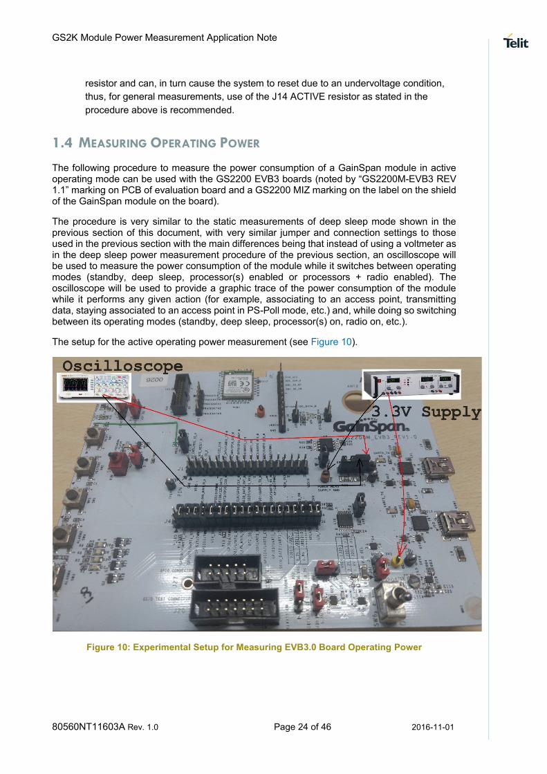
The procedure is very similar to the static measurements of deep sleep mode shown in the previous section of this document, with very similar jumper and connection settings to those used in the previous section with the main differences being that instead of using a voltmeter as in the deep sleep power measurement procedure of the previous section, an oscilloscope will be used to measure the power consumption of the module while it switches between operating modes (standby, deep sleep, processor(s) enabled or processors + radio enabled). The oscilloscope will be used to provide a graphic trace of the power consumption of the module while it performs any given action (for example, associating to an access point, transmitting data, staying associated to an access point in PS-Poll mode, etc.) and, while doing so switching between its operating modes (standby, deep sleep, processor(s) on, radio on, etc.).
The setup for the active operating power measurement (see Figure 10).
Figure 10: Experimental Setup for Measuring EVB3.0 Board Operating Power

GS2K Module Power Measurement Application Note
80560NT11603A Rev. 1.0 Page 25 of 46 2016-11-01
The setup looks as follows:
To perform this experiment, set up the experimental apparatus as follows:
1. Configure the EVB3.0 Board with the desired firmware.
2. Set the DC supply output voltage to 3.3V. Set the power limit to 500 mA.
3. Turn off the DC supply.
4. Set the jumpers and connectors of the EVB3.0 board (see Table 3).
GS2K Module Power Measurement Application Note
80560NT11603A Rev. 1.0 Page 26 of 46 2016-11-01
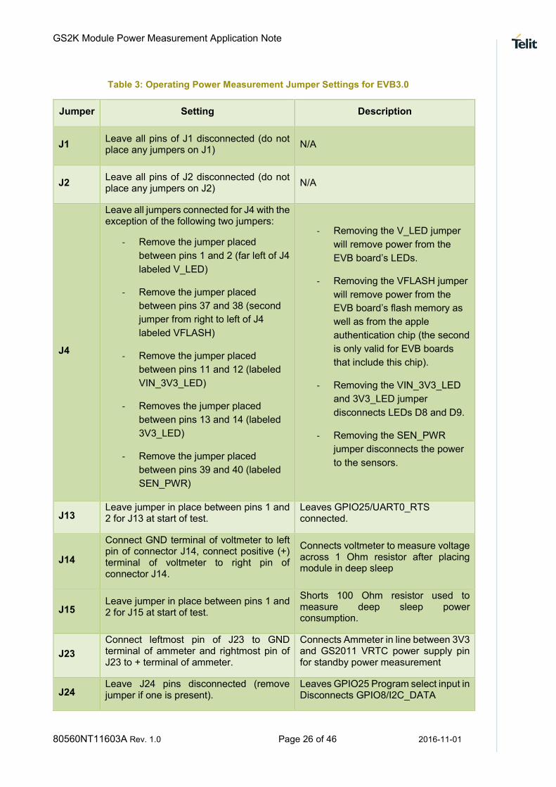
Table 3: Operating Power Measurement Jumper Settings for EVB3.0
Jumper Setting Description
J1 Leave all pins of J1 disconnected (do not place any jumpers on J1)
N/A
J2 Leave all pins of J2 disconnected (do not place any jumpers on J2)
N/A
J4
Leave all jumpers connected for J4 with the exception of the following two jumpers:
- Remove the jumper placed
between pins 1 and 2 (far left of J4
labeled V_LED)
- Remove the jumper placed
between pins 37 and 38 (second
jumper from right to left of J4
labeled VFLASH)
- Remove the jumper placed
between pins 11 and 12 (labeled
VIN_3V3_LED)
- Removes the jumper placed
between pins 13 and 14 (labeled
3V3_LED)
- Remove the jumper placed
between pins 39 and 40 (labeled
SEN_PWR)
- Removing the V_LED jumper
will remove power from the
EVB board’s LEDs.
- Removing the VFLASH jumper
will remove power from the
EVB board’s flash memory as
well as from the apple
authentication chip (the second
is only valid for EVB boards
that include this chip).
- Removing the VIN_3V3_LED
and 3V3_LED jumper
disconnects LEDs D8 and D9.
- Removing the SEN_PWR
jumper disconnects the power
to the sensors.
J13 Leave jumper in place between pins 1 and 2 for J13 at start of test.
Leaves GPIO25/UART0_RTS connected.
J14
Connect GND terminal of voltmeter to left pin of connector J14, connect positive (+) terminal of voltmeter to right pin of connector J14.
Connects voltmeter to measure voltage across 1 Ohm resistor after placing module in deep sleep
J15 Leave jumper in place between pins 1 and 2 for J15 at start of test.
Shorts 100 Ohm resistor used to measure deep sleep power consumption.
J23
Connect leftmost pin of J23 to GND terminal of ammeter and rightmost pin of J23 to + terminal of ammeter.
Connects Ammeter in line between 3V3 and GS2011 VRTC power supply pin for standby power measurement
J24 Leave J24 pins disconnected (remove jumper if one is present).
Leaves GPIO25 Program select input in Disconnects GPIO8/I2C_DATA

GS2K Module Power Measurement Application Note
80560NT11603A Rev. 1.0 Page 27 of 46 2016-11-01
J29 Leave jumper between pins 1 and 2 (closer to module on evaluation board).
N/A
J30 Leave jumper between pins 1 and 2 (Logic High – 3.3 V)
Sets the voltage for logic high for the module. Leaving the pins between 2 and 3 (Logic High – 1.8 V) does not have any impact on the power measurement.
J31
Place jumper between pins 2 and 3 (pins marked as Bench 3V3 and closer to module on evaluation board).
Selects a lab power supply (through test points TP2 and TP16) instead of USB connector as the power supply.
J32 Leave jumper placed between pins 2 and 3 of J32 (pins marked as STANDBY for J32 on evaluation board).
Enables module to operate in standby mode when needed (instead of setting it to operate in always on mode as selected by placing a jumper between pins 1 and 2 on J32).
J33 Leave J33 pins disconnected (remove jumper if one is present).
Disconnect GPIO9/I2C_CLK disconnected.
J34 Leave jumper between pics 1 and 2 N/A
J35
Choose one of the two options for the jumper position:
- Place jumper between pins 1 and
2
- Place jumper between pics 2 and
3.
The VREG jumper decides the input power to the module.
- If the jumper is placed between
pics 1 and 2, the on-board
regulator is bypassed and the
input to the module is 3.3 V.
- If the jumper is placed between
pics 2 and 3, the on-board
regulator is used and the imput
is 1.8 V.
Measure power on both settings to decide whether to use an on-board regulator for the design.
J36 Leave J36 pins disconnected (remove jumper if one is present)
N/A
J37 Leave jumper between pics 2 and 3 N/A
5. Either leave the oscilloscope free-running with a long capture period (5 seconds per
division will be a good selection for this purpose), or configure the oscilloscope trigger
as needed for the test in question (for example, if you want to start capturing when the
radio is turned on, set the trigger to rising edge and trigger threshold that is above 50
milliamperes but below 100 milliamperes) so that it will start capturing at the moment
the GainSpan chip reaches the desired state.

GS2K Module Power Measurement Application Note
80560NT11603A Rev. 1.0 Page 28 of 46 2016-11-01
6. It is also recommended to set the Oscilloscope to 50 mV per division, as that will give
enough resolution to observe all operating modes, but if zooming into a mode is
desired, a different amplitude setting may be selected for the oscilloscope as desired.
7. If a serial connection is needed to the EVB to measure the state of interest (for
example, if you need to issue Serial-to-Wi-Fi commands to ask the module to
associate to an access point) Connect the USB0 port on your EVB board to your
computer through a USB cable.
8. Power on the DC supply and perform any needed setup to reach the desired operating
state (whether that is issuing Serial to Wi-Fi commands via a serial terminal or any
other actions on other devices - access points, other Wi-Fi clients, any network
servers, etc.).
9. As a final step before measuring the power consumption on the scope, make sure that
if you have a USB cable connected to either the USB0 or USB1 ports on the EVB
board those are disconnected prior to conducting the measurement on the
oscilloscope, as depending on what is connected to these ports, they can create an
alternate ground that can impact the performed measurement.
10. The instantaneous power consumption will be observed on the oscilloscope as I =
Oscilloscope Voltage Measurement / J14 Active Resistance = I = Oscilloscope Voltage
Measurement / 1, in other words, the voltage seen in the oscilloscope will directly be
the module’s instantaneous power consumption.
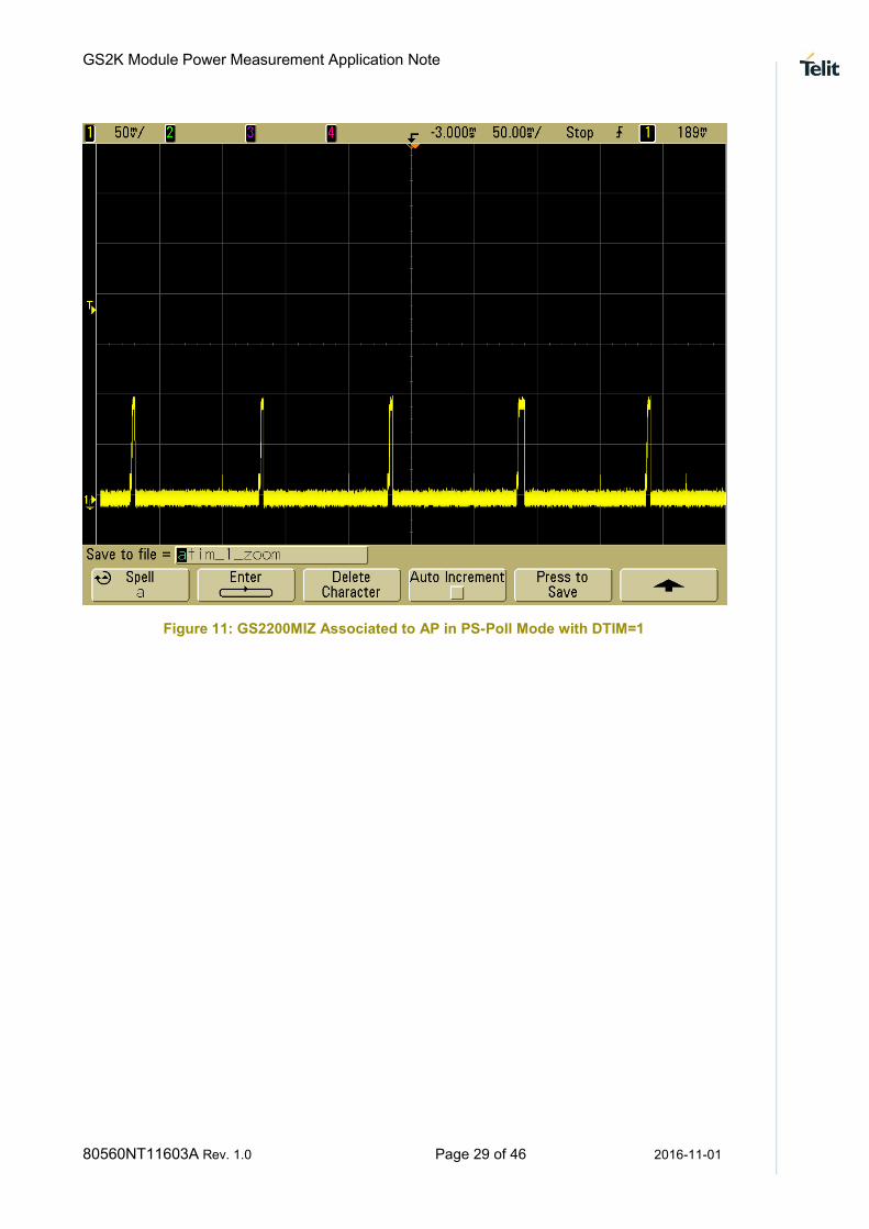
As a reference, the trace provided (see Figure 11) was obtained by associating a GS2200MIZ module to an access point and operating in PS-Poll mode with DTIM=1 periodicity with the above procedure and the following equipment:
Oscilloscope: Agilent MS06034A
Access Point: Linksys E1000 V2 with firmware version 2.1.02
GainSpan Evaluation Board: GS2200MIE-EVB3
GainSpan Wireless Firmware: 5.3.0 RC
GainSpan Application software: 5.3.0 RC Serial-to-Wi-Fi
GS2K Module Power Measurement Application Note
80560NT11603A Rev. 1.0 Page 29 of 46 2016-11-01
Figure 11: GS2200MIZ Associated to AP in PS-Poll Mode with DTIM=1

GS2K Module Power Measurement Application Note
80560NT11603A Rev. 1.0 Page 30 of 46 2016-11-01
Chapter 3 Power management States for SKB
The GS2200M Starter Kit Board (SKB) is an easy to use evaluation and development platform for GS2200M module-based products. It includes built-in power measurement features to facilitate estimated power consumption and battery life of the product. Power consumption is computed by multiplying measured voltage and current. This document specifies the current measurement aspects of the GS2200M Starter Kit Board (SKB). The GS2200M module’s supply voltage is constant – ~3.3V and theCurrent consumption varies with time. This document describes how to measure current consumption of the GS2200M module using various features of the GS2200M SKB. These techniques may be used to estimate power consumption and battery life of a product that will utilize the GS2200M.
1.5 POWER MEASUREMENT CIRCUITRY
The power measurement feature provides measuring the power drawn by the GS2200M and the external 1.8V regulator. It excludes the power consumed by the sensors, other peripherals and regulators. The power measurement circuitry as shown in Figure 12, consists of two shunt resistor options, selectable by switch SW6. These are in series with the GS2200M, after the sensor and peripheral load is excluded from power measurements. A current measuring amplifier amplifies the voltage drop over the selected shunt resistor to generate the power measurement signal. Power measurement at the bench supply source will not be accurate because they include power consumed by the other components on the board including LEDs, sensors, and the power measurement circuit. Hence bench supply source for measuring the power is not used.
Figure 12:Power Measurement Circuit
GS2K Module Power Measurement Application Note
80560NT11603A Rev. 1.0 Page 31 of 46 2016-11-01
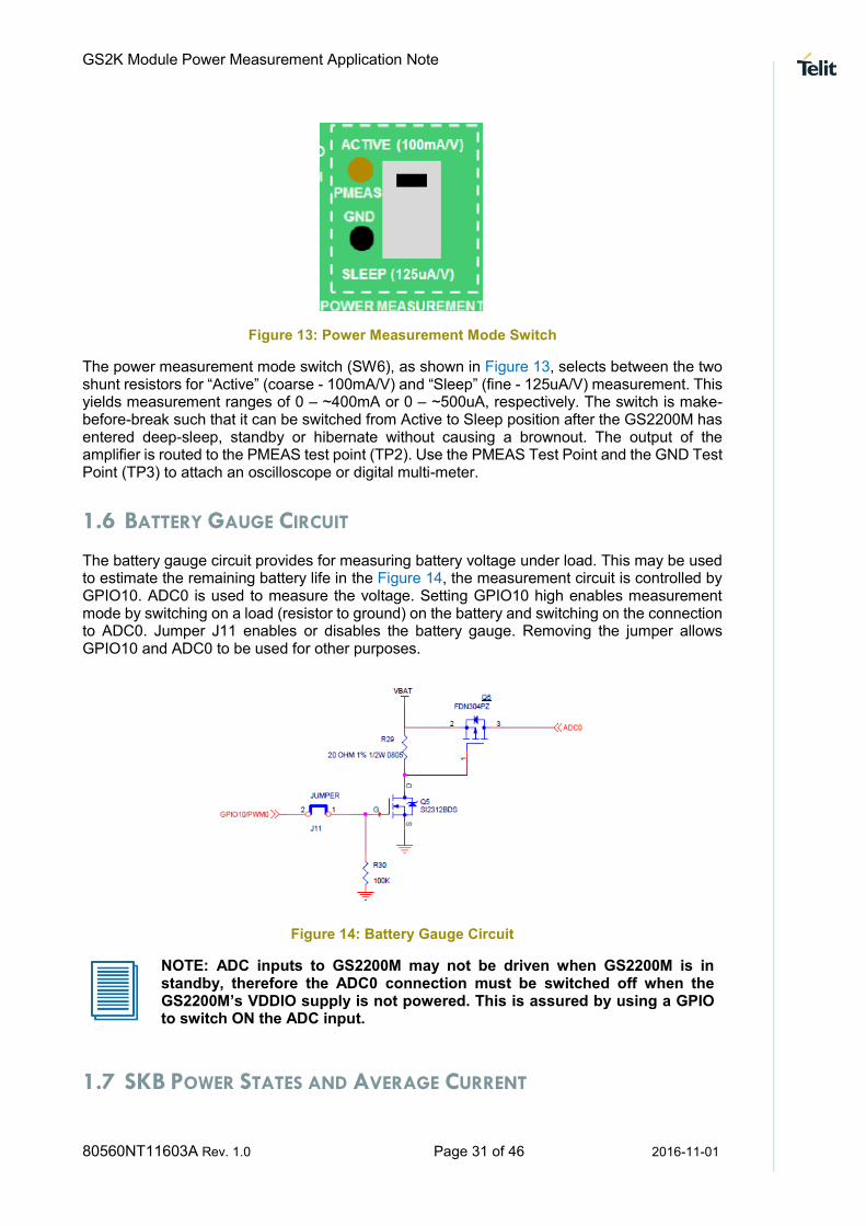
Figure 13: Power Measurement Mode Switch
The power measurement mode switch (SW6), as shown in Figure 13, selects between the two shunt resistors for “Active” (coarse - 100mA/V) and “Sleep” (fine - 125uA/V) measurement. This yields measurement ranges of 0 – ~400mA or 0 – ~500uA, respectively. The switch is make-before-break such that it can be switched from Active to Sleep position after the GS2200M has entered deep-sleep, standby or hibernate without causing a brownout. The output of the amplifier is routed to the PMEAS test point (TP2). Use the PMEAS Test Point and the GND Test Point (TP3) to attach an oscilloscope or digital multi-meter.
1.6 BATTERY GAUGE CIRCUIT
The battery gauge circuit provides for measuring battery voltage under load. This may be used to estimate the remaining battery life in the Figure 14, the measurement circuit is controlled by GPIO10. ADC0 is used to measure the voltage. Setting GPIO10 high enables measurement mode by switching on a load (resistor to ground) on the battery and switching on the connection to ADC0. Jumper J11 enables or disables the battery gauge. Removing the jumper allows GPIO10 and ADC0 to be used for other purposes.
Figure 14: Battery Gauge Circuit
NOTE: ADC inputs to GS2200M may not be driven when GS2200M is in standby, therefore the ADC0 connection must be switched off when the GS2200M’s VDDIO supply is not powered. This is assured by using a GPIO to switch ON the ADC input.
1.7 SKB POWER STATES AND AVERAGE CURRENT

GS2K Module Power Measurement Application Note
80560NT11603A Rev. 1.0 Page 32 of 46 2016-11-01
GS2200M module used in SKB, supports the following power states/modes as described in Table 4. Each mode consume different amount of current. Typical average current consumption for each mode is given below:
Table 4: Power States
• Power State
• Typical Average Current
• Comments
• Hibernate • 260 nA • SKB doesn’t support this measurement
• Standby • 4-8 µA •
• Deep Sleep • 450 – 600 mA •
• RX - Active • 85 mA •
• TX - Active • 250 mA •
NOTE: Average current can vary from module to module. It can also depend on the software version. Please refer to the “GS2200M Data Sheet” for more information on the power states. The above mentioned average current consumption is based on GEPS 5.3.0 software.
1.8 CONFIGURING THE SKB FOR CURRENT MEASUREMENT
In order to measure current, SKB should be loaded with an appropriate firmware. The SKB hardware jumpers must be configured to select the proper power source as well as the power measurement mode. The following sections gives these configurations:
Building the S2W Firmware using SDK Builder
Please refer to Appendix A for instructions on how to build the S2W firmware using GainSpan SDK Builder.
Programming the S2W Firmware into the SKB
Please refer to Appendix B for instructions on how to program the S2W firmware using GS Flash Programming tool.
Jumper Settings for Current Measurements
The recommended settings for other jumpers for power measurement is described in Table 5. Once the power source is selected for measuring the current, review the settings using the below table:
Table 5: Recommended Jumper Settings for Power Measurements
Header Jumper Settings Comments

GS2K Module Power Measurement Application Note
80560NT11603A Rev. 1.0 Page 33 of 46 2016-11-01
J18 [1-2] and [7-8]
Others: Don’t care
Enable USB serial port connections to UART0 TX and RX signals
J20 Don’t care SPI master/slave jumpers
J11 Don’t care Battery Gauge enable jumper
J14 1.8V [2-3] VREG power source. Select “1.8V” [2-3] for lowest power. Select 3.3V [1-2] if omitting external 1.8V regulator from end product design.
J15 Don’t Care Power source for the sensors
J16 Don’t care Power LED enable jumper
Connecting the Bench Supply and Digital Multi -Meter
1. Set power source jumpers to “Bench Supply”, as per the below table:
Table 6: Power Source Selection
Power Source J19 J12 J13
Bench Supply Don’t Care Don’t Care BENCH [1-2]
Battery Don’t Care BATT [2-3] [2-3]
USB USB [1-2] [1-2] [2-3]
Arduino +5V [J3 pin 5] +5V [2-3] [1-2] [2-3]
2. Set the DC supply output voltage to 3.3V and set the current limit to 500 mA.
3. Turn OFF the DC supply.
4. Connect the positive terminal of bench supply to the 3.3V Test Point [TP4] and the
negative terminal to GND Test Point [TP5] on the SKB.
5. Connect the Digital Multi-Meter’s (DMM) positive terminal to the PMEAS Test Point
[TP2] and the negativeCOM terminal to the GND Test Point [TP3].
Make sure that the power measurement mode switch [SW6] is set to the ACTIVE position.
Configuring the Serial Port
Please refer to Appendix C for instructions on how to configure the serial port.

GS2K Module Power Measurement Application Note
80560NT11603A Rev. 1.0 Page 34 of 46 2016-11-01
1.9 MEASURING TRANSMIT CURRENT
Following steps are used to measure the transmit power current of 802.11b/g/n base mode i.e. 1Mbps/6Mbps/6.5Mbps transmit date rates.
1. Set the power measurement mode switch [SW6] to the ACTIVE position.
2. Power Cycle the SKB using the switch on the bench supply or, if bench supply is not
used, SKB’s power switch [SW5] can be used instead.
3. Issue the following AT commands to the SKB using the serial terminal program.
(These commands will generate a continuous 802.11b transmit signal at 1Mbps.)
4. The DMM will display the average transmit current.
Table 7: AT Commands and Comments
AT Commands Comments
at+wrfteststart
at+wtx100test=6,0,15,0,0,0,0,1,1,0,0,0,0,1
802.11b transmit signal at 1Mbps
Expected Average TX current - ~215 mA
AT+WRFTESTSTOP
AT+WRFTESTSTART
at+wtx100test=6,0,21,0,0,0,0,1,0,0,0,1,3,0
802.11g transmit signal at 6Mbps
Expected Average TX current - ~265 mA
AT+WRFTESTSTOP
AT+WRFTESTSTART
at+wtx100test=6,0,21,0,0,0,0,1,0,0,0,1,0,2
802.11n transmit signal at MCS0
Expected Average TX current - ~265 mA
NOTE: Please refer “GS2200M S2W Adapter Command Reference Guide” for details on the above AT commands as well as generating signals at various data rates.
1.10 MEASURING RECEIVE CURRENT
Following are the steps used to measure Receive Current:
1. Set the power measurement mode switch [SW6] to the ACTIVE position.
2. Power cycle the SKB.
3. Issue the following AT commands to the SKB using the serial terminal program.
(These commands will turn the receiver ON and enable asynchronous frame
reception.)
4. DMM will display the average receive current.

GS2K Module Power Measurement Application Note
80560NT11603A Rev. 1.0 Page 35 of 46 2016-11-01
AT Commands Comment
at+wrfteststart
at+wrxtest=6,0,536870912,00:00:00:00:00:00,0 Expected Average TX current - ~85 mA
NOTE: Please refer to the “GS2200M S2W Adapter Command Reference Guide” for details on the above AT commands.
1.11 MEASURING DEEPSLEEP CURRENT
Following are the steps used to measure DeepSleep current for GS2200M SKB.
1. Set the power measurement mode switch [SW6] to the ACTIVE position.
2. Power Cycle the SKB
3. Issue the following AT commands to the SKB using the serial terminal program. (This
command will put the module into DeepSleep Mode.)
4. Set the power measurement mode switch [SW6] to the SLEEP position.
5. DMM will display the average receive current.
AT Commands Comment
at+psdpsleep=999999999999,1,1 Expected Deep Sleep Current - ~400 µA
NOTE: Please refer to the “GS2200M S2W Adapter Command Reference Guide” for details on the above AT commands.
1.12 MEASURING STANDBY CURRENT
Following are the steps used to measure the standby power current for GS2200 SKB.
1. Set the power measurement mode switch [SW6] to the ACTIVE position.
2. Power Cycle the SKB.
3. Issue the following AT commands to the SKB using the serial terminal program.
(These commands will put the module into Standby Mode.)
4. Set the power measurement mode switch [SW6] to the SLEEP position.

GS2K Module Power Measurement Application Note
80560NT11603A Rev. 1.0 Page 36 of 46 2016-11-01
5. DMM will display the average receive current**.
AT Commands Comment
at+psstby=999999999999,1,1 Expected Standby Current - ~5-8 µA
NOTE: In Rev 1.2 of the SKB all current measurements are offset by about 14 µA due to current that flows into the -IN pin of the amplifier. When measuring very low current in the order of µA, please subtract 14 µA from the actual measurement. The offset can be determined by measuring the voltage drop across R25 with a multi-meter and dividing by the resistance (62.6 ohms).
Also, Please refer to the “GS2200M S2W Adapter Command Reference Guide” for details on the above AT commands
1.13 MEASURING PS-POLL AVERAGE CURRENT
During PS-POLL the current can vary from few µA to 100 mA very rapidly. To capture these variations an instrument with very high sampling rate and dynamic range is required. Usage of DMM or scope that can sample at high frequency, over a large dynamic range and average over a long period is suggested. This could be connected to PMEAS to integrate the power curve over a long period. Another option is using the 6705B DC Power Analyzer from Key Sight or other instruments with similar capabilities for accurate average current measurements. However, scope to measure the average current and a bench supply to power the SKB is used, as in previous sections.
PS-POLL with Standby Average Current Measurements
1. Power Cycle the SKB.
2. Set the power measurement mode switch [SW6] to the ACTIVE position.
3. Issue the following AT commands to the SKB using the serial terminal program.
(These commands will put the module into PS-POLL mode and Standby in between.)
4. Use an oscilloscope to capture the current profile similar to the one shown in Figure
15.

GS2K Module Power Measurement Application Note
80560NT11603A Rev. 1.0 Page 37 of 46 2016-11-01
AT Commands Comment
at+wrxactive=0
at+wrxps=0
at+wkeepalive=0
at+wieeepspoll=2,,2,5
at+wieeepspoll=1
at+ndhcp=1
at+wa=AppleExtreme
at+psstbybwbeaconconf=0,1
at+psstbybwbeacon=1
Standby between PS-POLL & DTIM interval 5
Note – You can try different DTIM intervals by changing the value 5 to desired DTIM interval.
For example at+wieeepspoll=2,,2,3 will use
DTIM interval of 3
Expected Average Current for DTIM 5 - ~1 mA
NOTE: Please refer to the “GS2200M S2W Adapter Command Reference Guide” for details on the above AT commands.
Based on the above AT commands, the SKB exits from standby every 510ms (5th Beacon based on beacon interval of 102ms). As shown in Figure 15, the GS2200M wakes up from standby at P1 to turn the receiver ON and receive the beacon, then goes back into standby at P2. In order to calculate the average current drawn, the average current from time P1 through time P2 is accounted. Based on previous measurements, we know the GS2200M consumes 5-8 µA in standby mode. This data can be used and collected while the GS2200M is active to calculate the average current consumed over the entire polling cycle from the start of the cycle to the start of the next polling cycle. Based on polling every 510ms, the time in standby will be 510 – (P2 – P1) ms.
Average current consumed over one polling cycle is calculated using the following steps.
1. Export the data from your oscilloscope to a CSV file.
2. Import the CSV data into a spreadsheet program.
3. Scan the data and record the times P1 (where measured voltage first rises from the
standby level) and P2 (where measured voltage returns to the standby level).
4. Use the spreadsheet to calculate the average of measurements taken between times
P1 and P2. Define this value as Vactive, the average voltage while the GS2200M is
active.
5. Calculate the average current over an entire polling cycle using the following formulas:
Iavg = (Tactive * Iactive + Tstby * Istby) / (Tactive + Tstby)
or
Iavg = ((P2 – P1)ms * (Vactive * 100mA/V) + (510ms – (P2 – P1)ms) IstbymA) / 510ms

GS2K Module Power Measurement Application Note
80560NT11603A Rev. 1.0 Page 38 of 46 2016-11-01
Figure 15: Current Profile in using PS-Polling with Standy between Beacons
PS-POLL with DeepSleep Average Current Measurements
1. Power Cycle the SKB.
2. Issue the following AT commands to the SKB using the serial terminal program.
(These commands will put the module into PS-POLL mode and Standby in between.)
3. Use a power analyzer or DMM or Oscilloscope to measure measurement.
AT Commands Comment
at+wrxactive=0
at+wrxps=0
at+wieeepspoll=2,,2,1
at+wieeepspoll=1
at+wkeepalive=0
at+ndhcp=1
at+wa=AppleExtreme
at+psdpsleep=99999999,1,1,1
DeepSleep between PS-POLL & DTIM interval 1
Custom wake up independent of AP DTIM setting.
Note – You can try different DTIM intervals by changing the value 1 to desired DTIM interval.
For example at+wieeepspoll=2,,2,3 will use DTIM interval of 3 .
Expected Deep Sleep Current for DTIM 1 - ~3.5 mA
NOTE: Please refer to the “GS2200M S2W Adapter Command Reference Guide” for details on the above AT commands.
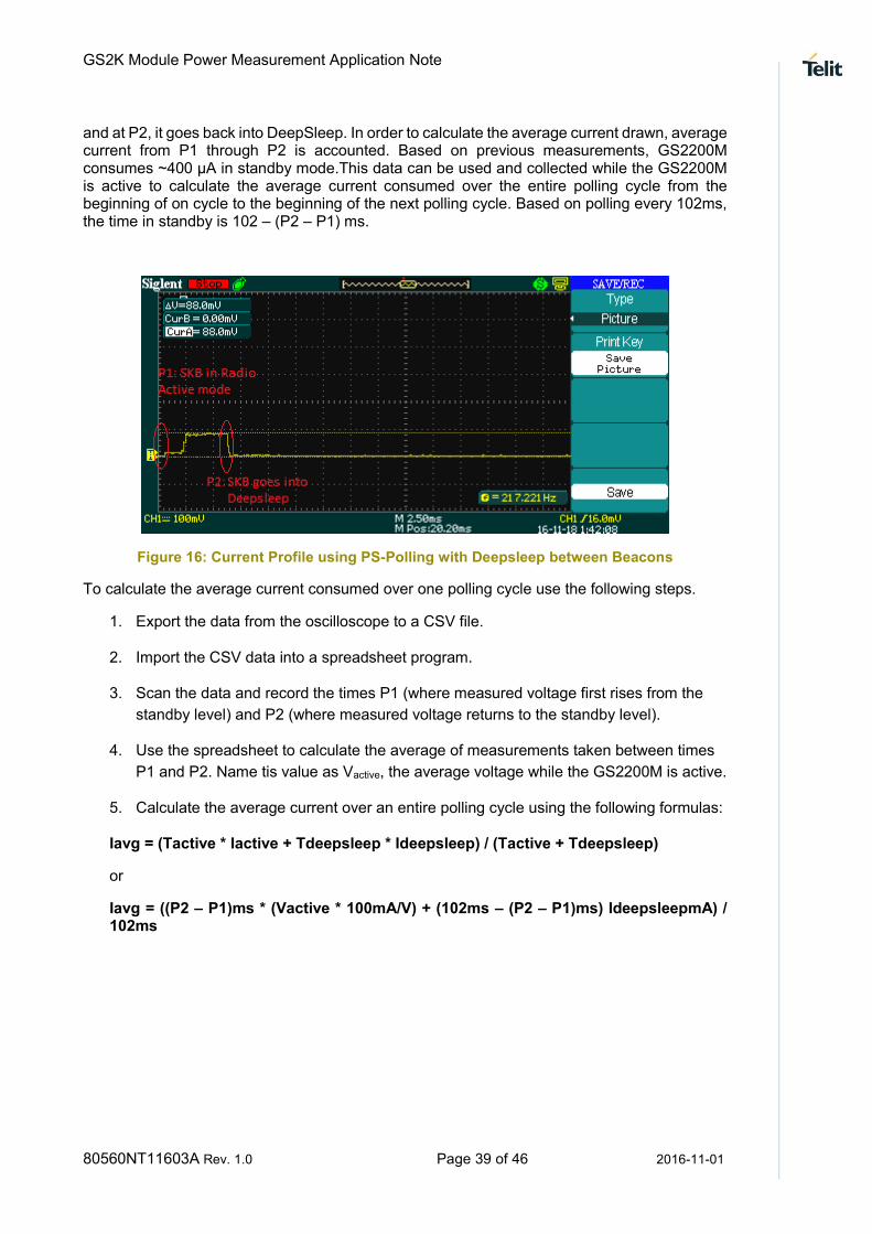
Based on the above set of AT commands, SKB exits from DeepSleep every 102ms (beacon interval is 102ms). As shown in Figure 16, the SKB turns ON the receiver to receive the Beacon
GS2K Module Power Measurement Application Note
80560NT11603A Rev. 1.0 Page 39 of 46 2016-11-01
and at P2, it goes back into DeepSleep. In order to calculate the average current drawn, average current from P1 through P2 is accounted. Based on previous measurements, GS2200M consumes ~400 µA in standby mode.This data can be used and collected while the GS2200M is active to calculate the average current consumed over the entire polling cycle from the beginning of on cycle to the beginning of the next polling cycle. Based on polling every 102ms, the time in standby is 102 – (P2 – P1) ms.
Figure 16: Current Profile using PS-Polling with Deepsleep between Beacons
To calculate the average current consumed over one polling cycle use the following steps.
1. Export the data from the oscilloscope to a CSV file.
2. Import the CSV data into a spreadsheet program.
3. Scan the data and record the times P1 (where measured voltage first rises from the
standby level) and P2 (where measured voltage returns to the standby level).
4. Use the spreadsheet to calculate the average of measurements taken between times
P1 and P2. Name tis value as Vactive, the average voltage while the GS2200M is active.
5. Calculate the average current over an entire polling cycle using the following formulas:
Iavg = (Tactive * Iactive + Tdeepsleep * Ideepsleep) / (Tactive + Tdeepsleep)
or
Iavg = ((P2 – P1)ms * (Vactive * 100mA/V) + (102ms – (P2 – P1)ms) IdeepsleepmA) / 102ms

GS2K Module Power Measurement Application Note
80560NT11603A Rev. 1.0 Page 40 of 46 2016-11-01
Appendix A Building the S2W Firmware using SDK Builder
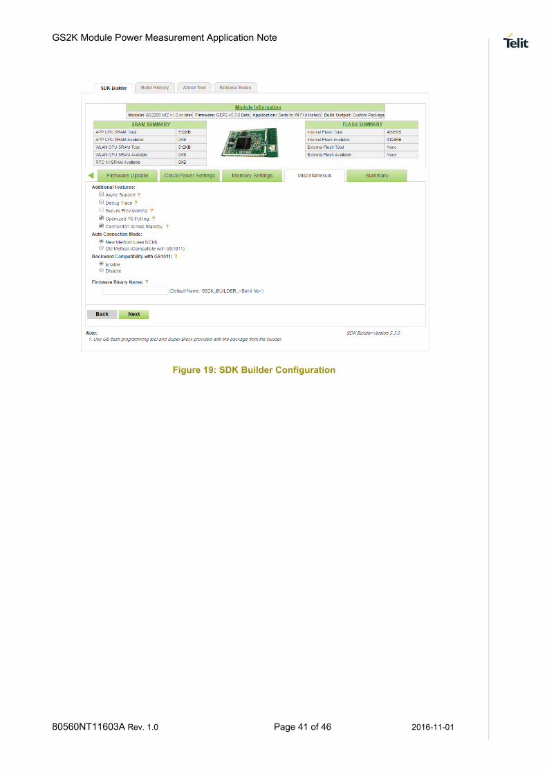
To build S2W, login to GainSpan customer portal and build the firmware. Please refer to the “SDK Builder User Guide” for detailed instructions. While building the S2W application, ensure the following features are selected, as shown in Figure 17, Figure 18 and Figure 19
Figure 17: SDK Builder Configuration
Figure 18: SDK Builder Configuration
GS2K Module Power Measurement Application Note
80560NT11603A Rev. 1.0 Page 41 of 46 2016-11-01
Figure 19: SDK Builder Configuration

GS2K Module Power Measurement Application Note
80560NT11603A Rev. 1.0 Page 42 of 46 2016-11-01
Appendix B Programming SKB with GainSpan Firmware
Once the S2W firmware is built, as described in Appendix A, program the SKB with the firmware
provided in “gs2200_s2w_5.3.0.bin”. Connect the mini-USB cable to the UART port on the SKB and other end to the PC. Power ON the SKB through USB. In that case, J19 jumper should be set to USB as a source of power and SW6 switch must be set to “ACTIVE”. Turn the SKB ON by setting SW5 switch to “ON” position. Once the USB port is enumerated (if using for the first time), then program the SKB.
Launch the GainSpan Serial Flash Programmer application from
“\Tools\GS_programming_tool”. Select “UART” to select interface and select the appropriate UART port.
If 115200 baud rate is chosen, as shown in the Figure 17, press and hold both “PROGRAM” [SW2] switch and “RESET” [SW4] switch, then release “PROGRAM” SW4 switch.
Alternatively, if 921600 baud rate is chosen, press and hold both “PROGRAM” and “RESTORE” [SW1] then release the “RESET” button.
Figure 20: Program Mode and GainSpan Flash Programmer
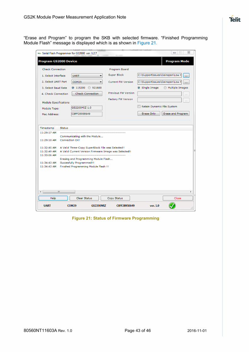
Once the SKB is detected successfully by the GainSpan Flash Programmer, select the superblock to be used “Super Block” and select the SKB firmware under “Current FW Version”. Serial Flash Programmer displays, if a valid superblock and firmware is selected. Now click on
GS2K Module Power Measurement Application Note
80560NT11603A Rev. 1.0 Page 43 of 46 2016-11-01
“Erase and Program” to program the SKB with selected firmware. “Finished Programming Module Flash” message is displayed which is as shown in Figure 21.
Figure 21: Status of Firmware Programming
GS2K Module Power Measurement Application Note
80560NT11603A Rev. 1.0 Page 44 of 46 2016-11-01
Appendix C Configuring Serial Port for Power Measurement
1. Connect the USB port on the SKB board to the computer through a USB cable.
2. Start a terminal program (Tera Term VT, HyperTerminal, or Putty).
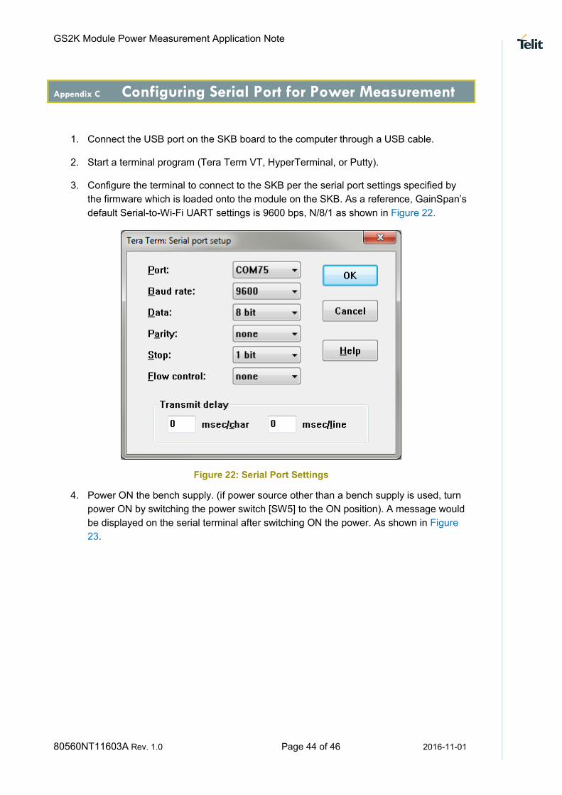
3. Configure the terminal to connect to the SKB per the serial port settings specified by
the firmware which is loaded onto the module on the SKB. As a reference, GainSpan’s
default Serial-to-Wi-Fi UART settings is 9600 bps, N/8/1 as shown in Figure 22.
Figure 22: Serial Port Settings
4. Power ON the bench supply. (if power source other than a bench supply is used, turn
power ON by switching the power switch [SW5] to the ON position). A message would
be displayed on the serial terminal after switching ON the power. As shown in Figure
23.

GS2K Module Power Measurement Application Note
80560NT11603A Rev. 1.0 Page 45 of 46 2016-11-01
Figure 23: Serial Port Output