group 6 design report 2 copy
TRANSCRIPT
EML 4501 – Mechanical System Design
Design Report 2 Razor e300 Scooter
Design Group 6: Jose Cortes
Laura DeTardo Matthew DeVries Jonathan Franco
Massimiliano Giffuni Matthew Vitarelli

Table of Contents Full Solidworks Assembly……………………………………….. 1 Introduction………………………………………………………. 2 Part List and Descriptions………………………………………... 3 Functional Requirements…………………………………………. 12 Pros and Cons…………………………………………………….. 45 Material Identification……………………………………………. 46 Assembly Process………………………………………………… 57 Handling and Insertion Times………………………………… 92 Cost Analysis……………………………………………………... 96 How It Works…………………………………………………….. 97 Performance Analysis…………………………………………….. 112 Appendix A: Closure Equations………………………………….. 118 Appendix B: Solidworks Drawings………………………………. 151 Appendix C: Reference Charts…………………………………… 207
Introduction
The following design report analyzes the Razor E300 electric scooter and its individual components. The design requirements, part descriptions, pros and cons of the machine, material identification, the assembly process, a cost analysis and detailed analyses of the various systems of the machine will be discussed throughout this report.
The design requirements list the individual components, what tasks they complete and how those tasks are accomplished. The pros and cons of the machine evaluate the functions and components of the scooter as a whole and determine whether or not it helps or hinders the overall workings of the scooter.
Material identification of the components consists of two separate tests. Metal components were separated into magnetic and non-magnetic and then further testing such as determining the density of the material. For non-metal components, the plastic identification flow cart was followed. The components were held over a flame while the smoke color, flame color, smell and any changes in the composition of the parts were noted.
The assembly process consists of both verbal instructions with pictures on how to construct the scooter and handling and insertion times with angles to estimate the overall time it takes to assembly the full scooter. A cost analysis was done on the chain guard to determine the manufacturing costs for a plastic injection molding part.
In-depth analysis was carried out to further understand the mechanical, thermal, and electrical systems of the scooter. Torque calculations, braking distance and acceleration were evaluated for the drive train, which includes the motor chain and rear wheel assembly. Closure equations were also calculated to ensure the tolerances for each assembly fall within an acceptable range. Heat transfer analysis was done for the motor to determine how well the motor dissipates the heat that it generates. An electrical diagram was created to show how the electrical current flows between the throttle and the motor.
Group 6 pg 2
Part List and Description
Chain Drive Assembly: Motor- The motor creates torque to generate power to propel the scooter. It utilizes magnetic and
electrical fields to convert electrical energy to mechanical power. Chain- The chain wraps around the motor sprocket and translates the motion from that to the
wheel sprocket. The links of the chain correlate with the gaps between the teeth of the sprocket.
Sprocket- The sprocket is a gear with teeth on the outer rim that is connected to the clutch. It
transmits rotary motion from the motor to the wheel via the chain. The teeth of the sprocket mesh with the links of the chain.
Chain Tensioner- The chain tensioner pushes against and creates tension on the chain to
eliminate slack. It contains a roller at the chain end to eliminate friction and not interfere with the rotation of the chain.
Tensioner Bolt- The tensioner bolt fits through a matching hole in the chain tensioner and anchor
it to the frame of the scooter. Tensioner Spring- The tensioner spring fits around the screw end of the chain tensioner and is
what creates the tension on the chain. One end is fixed on frame, while the other is wrapped around the edge of the tensioner.
Motor Mount Screws- There are four screws that attach the motor to the frame. They are
available from McMaster.com with part number 91420A425. Rear Wheel Assembly: Tube- The tube goes inside of the tire of the scooter. The tube inflates to make the scooter ride
smooth and absorb the bumpy rides. The tube has the Schrader valve connected to it which is used to inflate the tube when air is needed.
Tire- The tire is made out of a rubber material that is resistant to the rough surface. It has a surface
pattern which allows for a good traction to the ground and dry and wet conditions. Due to the tube pressure the tire is able to form a tight seal with all the wheel components and rotate around the axle to move the scooter.
Wheel Axle Hub-this part contains ball bearings at its end and has an inner bearing rod inside of
it. The axle goes inside of these parts. Since the wheel axle hub is attached to the wheel hub and tire, it provides the main frame for the complete wheel assembly as it rotates around the axle.
Wheel Hub- part of the wheel assembly that is able to attach the tire and tube assembly to the
wheel axle hub. The two wheel hubs are shaped and assembled to fit the inflated tube/tire around it and form a press fit. Since the wheel axle hub is attached by four screws to the wheel hub they are able to move together. The rear wheel axle hub is threated at its ends,
Group 6 pg 3
these allow for the brake assembly and the clutch/sprocket assembly to attach to the rear wheel.
Screw-washer- The four screws (93235A244 from McMaster-Carr) of the wheel assembly form
the link between the wheel axle hub and wheel hub. The washers for the screw assembly add more space and protect the parts between the screw and the face of the wheel axle hub.
Axle- the axle provides the link between the wheel assembly and the scooter’s fork. The axle
passes through the wheel axle hub, the brake, the clutch, and the spacers. Has the shape of a cylinder in order for the wheel to rotate freely around it. The threading at the two ends of the axle are used to lock the axle to the frame by the use of end nuts.
Brake Drum- the brake drum is fastened to one of the threated parts of the wheel axle hub. The
brake drum is the part that stops the wheel from rotating when the brake is applied. The brake caliper comes into contact with the outer surface of the brake drum to stop its motion.
Brake Assembly- full assembly of the brake that passes through the rear wheel axle. This is
connected to the hand brake handle by a cable. The brake goes around the brake drum in order to stop the wheel from rotating when the user brakes the scooter.
Sprocket/Clutch Assembly- this assembly is fastened to the wheel axle hub threated end. Provides
the link between motor torque and the wheel torque. The chain is connected to the sprocket which then translate the torque from the motor’s sprocket to the rear wheel.
Spacers- The two spacers of varying thickness located at each side of the wheel add the space
necessary to keep the wheel assembly from sliding around the axle. Washers- there are four washers of different sizes and shape that are used to protect the frame and
the ball bearings from the rotations of the wheel and the pressure of the end nuts to the frame. The larger washer has a cut which allows another component of the wheel to fit in the overall assembly. The two split lock washers change shape by applied pressure, adding more space.
End Nut- the two end nuts are threaded at the two ends of the axle. These are fastened in order to
lock the wheel and the frame into one assembly by the use of the axle. Front Wheel Assembly: Tube- The tube goes inside of the tire of the scooter. The tube inflates to make the scooter ride
smooth and absorb the bumpy rides. The tube has the Schrader valve connected to it which is used to inflate the tube when air is needed.
Tire- The tire is made out of a rubber material that is resistant to the rough surface. It has a surface
pattern which allows for a good traction to the ground and dry and wet conditions. Due to the tube pressure the tire is able to form a tight seal with all the wheel components and rotate around the axle to move the scooter.
Group 6 pg 4
Wheel Axle Hub-this part contains ball bearings at its end and has an inner bearing rod inside of it. The axle goes inside of these parts. Since the wheel axle hub is attached to the wheel hub and tire, it provides the main frame for the complete wheel assembly as it rotates around the axle.
Wheel Hub- part of the wheel assembly that is able to attach the tire and tube assembly to the
wheel axle hub. The two wheel hubs are shaped and assembled to fit the inflated tube/tire around it and form a press fit. Since the wheel axle hub is attached by four screws to the wheel hub they are able to move together.
Screw-washer- The four screws (93235A244 from McMaster-Carr) of the wheel assembly form
the link between the wheel axle hub and wheel hub. The washers for the screw assembly add more space and protect the parts between the screw and the face of the wheel axle hub.
Axle- the axle provides the link between the wheel assembly and the scooter’s fork. The axle
passes through the wheel axle hub. Has the shape of a cylinder in order for the wheel to rotate freely around it. The threading at the two ends of the axle are used to lock the axle to the frame by the use of end nuts.
Spacers- The two spacers located at each side of the wheel add the space necessary to keep the
wheel assembly from sliding around the axle. Washers- there are four thin washers that are used in order to protect the frame and the ball bearings
from the rotations of the wheel and the pressure of the end nuts to the frame. The two split lock washers change shape by applied pressure, adding more space.
End Nut- the two end nuts are threaded at the two ends of the axle. These are fastened in order to
lock the wheel and the frame into one assembly by the use of the axle. Clutch Assembly: Cutch Outer Rim- The outer rim of the clutch is the central part of the clutch that attaches to the
sprocket. It is symmetric about its central axis and has a circular step pattern in the central circular extrusion.
Cutch Big Side Rim- this rim is the wider of the two smaller diameter rims. It houses the spring
and rocker arm, as well as providing a raceway for the ball bearings. It has internal threading on its inner face that allows it to be screwed onto the rear wheel axle hub.
Cutch Small Side Rim- this rim is the thinner of the two smaller diameter rims. It provides a
raceway for ball bearings and screws onto the big side rim. Cutch Rocker Arm- This is a small steel piece with a rounded side that fits into a notch in the big
side clutch. When the spring is put in place, its free end raises and interacts with the step pattern in the outer rim.
Group 6 pg 5
Cutch Spring- This is a single revolution spring with a ninety degree turn. It fits in the notch in the big side rim as well as the notch in the rocker arm. It secures the rocker arm and helps it to rise up and interact with the step pattern in the outer rim.
Ball Bearings- These are small steel ball bearings that run in the raceways of the three rims.
When the raceways are lubricated the bearings help to have smooth rolling. There are ninety-four ball bearings in the clutch assembly.
Washers- There are four washers of differing thicknesses in the clutch assembly. They fit around
the big side of the clutch and ensure that there is enough spacing for the ball bearings. Screw- There are four screws that attach the outer rim of the clutch to the rear wheel sprocket.
The screws are available on McMaster.com as part number 91280A325. Nut- There are four nuts that screw onto the screws that hold the outer rim of the clutch to the
sprocket. They are available on McMaster.com as part number 90591A151. Brake Assembly: Brake Casing- The brake casing is a metal shell that is used to attach the brake components to the
frame and keep them in the position. It also protects the brake components from outside impact.
Brake Caliper- The brake caliper is a flexible metal piece with a ceramic pad screwed to one
side. It rests inside the brake casing and contracts when the brake cable is pulled to provide frictional stopping force.
Latch- The latch is a flat metal v-shaped piece that connects the brake cable to the brake caliper
so the brakes can be applied when the brake cable is pulled. Torsional Spring- The torsional spring is a small spring that hooks around the latch to provide
rotational force to counter the force of the brake cable. It returns the latch to original position to release the brakes after each use.
Brake Washer- Washers used in the brake assembly to create space between fasteners and key
components. Brake Nuts- The brake nuts are hexagonal nuts used to secure the latch to the brake casing and
the cable screw to the latch to prevent components from moving from their critical locations.
Cable Screw- The cable screw is a screw with a hole near the head to allow the brake cable to
pass through. It is used to secure the brake cable to the latch so the latch and brake caliper will move when the brake cable is pulled.
Brake Cable- The brake cable is a insulated wire that connects the brake handle to the latch to
transfer the motion of the brake handle to the brake caliper to apply the brake.
Group 6 pg 6
Frame Assembly: Frame Assembly- The frame assembly is the steel component that supports the rider during
operation, and houses or attaches all other subassemblies. Front Fork Holder- The front fork holder is the curved, vertical frame extrusion through which
the front fork is secured. Frame Rail- The frame rails are the long, curved extrusions that have circular cross sections that
run lengthwise along the scooter. They support rider load and are the base for the frame assembly. The frame rail also has holes with which to attach the deck.
Front Filler- The front filler is the small piece that attaches to the front fork holder and frame
rails in the frame assembly. The major functionality of this part is aesthetics. Rear Wheel Right- The rear wheel right is the frame section that is attached to the right hand
frame rail and has a slot into which the right side of the rear axle fits. It also has holes for the chain guard, chain tensioner, and chain tensioner spring.
Rear Wheel Left- The rear wheel left is the frame section that is attached to the left hand frame
rail and has a slot into which the left side of the rear axle fits. Rear Support- The rear support is the part of the frame that attaches to the rear wheel sections
and is shaped around the wheel. It ensures that the rider does not come into contact with the rear wheel during operation and also has holes with which to attach the deck.
Battery Box Support- The battery box support is the part of the frame that supports and protects
the black battery box. In addition, this component has threaded holes with which the battery box, deck, motor and battery bar are attached.
Rear Cross Section- The rear cross section is a trapezoidal shaped bar that maintains the distance
between the frame rails and adds structural integrity. It has holes with which the motor is attached.
Battery Box Assembly: Battery Box Assembly- The battery box assembly includes the battery box as well as all
components that are housed within it or attached to its structure. Battery Box Door- The battery box door is the plastic extrusion that fits into a slot on the battery
box wall. The purpose of this part is to allow easy access to the wires while it is removed, but protect the internal components from the environment when it is in place.
Reset Button- The reset button is the circular plastic button that is mounted in the wall of the
battery box. Its function is to reset the battery in the case of malfunction. Reset Button Nut- The reset button nut is a circular plastic piece that screws onto the reset button
and keeps the reset button in place.
Group 6 pg 7
On/Off Switch Casing- This part is a plastic piece that secures the on/off switch in place and
houses the electrical components that allow the switch to function. It also has connections that connect to the battery.
On/Off Switch- This part is a red plastic piece that is physically flipped to cause closed circuit to
be formed, effectively turning on the scooter. Battery Charge Plug- The battery charge plug is a circular metal piece whose face matches up to
the port of the battery charger. In effect, this piece is the electrical link from an electrical outlet to the scooter. This component is housed in the wall of the battery box.
Battery Charge Plug Nut- This part is a metal nut that screws onto the charge plug, keeping it in
place. Battery Charge Plug Cap- This part is a rubber cap that attaches around the plug, as well as
fitting around the mouth of the plug. The purpose of this part is to protect the face of the plug from contaminants during use, while still able to move so that the battery can be charged.
Processor- The processor is an electrical component that interprets the demands of the user and
attempts to carry them out. This part is screwed into the floor of the battery box. Battery- These two components store and distribute the electrical power of the scooter. Each
battery is a 12 volt, 9 Ampere hour battery, and each is housed in the battery box. Processor Screw- These two screws are used to secure the processor housing unit. They are
McMaster screws part number 92005A220. (Source: McMaster.com) Connector Clips- These are generic clips that allow for connection and disconnection of
electrical circuits. There are five male and five female clips in this assembly. Scratch Pad- This is a rectangular pad that fits between the battery and the battery box bar. Its
purpose is to keep the bar from scratching the batteries as well as preventing possible vibration.
Battery Box Bar- This is a long, thin steel member that acts as a method of protection for the
components of the battery box assembly from the rider mass. It has two holes with which it is attached to the frame.
Battery Box Screw- These two screws are used to secure the battery box bar. They are McMaster
screws part number 90116A307. (Source: McMaster.com)
Group 6 pg 8
Front Fork Assembly: Front Fork Bar- The front fork bar is a Y-shaped frame made from mild steel that acts as a
connection between the handlebars, scooter body, and front axle. It rotates the front axle with the handlebars to transmit steering motion.
Bearing Washers- The bearing washers are metal rings that hold twenty exposed ball bearings.
The bearing washers are used on each side of where the front fork bar connects to the scooter body to reduce friction when the front fork bar is turned to steer.
Plug- The plug is a plastic cap that fits into the bottom of the central pipe on the front fork bar. It
prevents the loss of internal nut if it comes lose and to prevent dirt or debris from getting inside the pipe.
Lower Headset Nut- The lower head set nut is a steel fastener that is used to secure the
connection between the front fork bar and the scooter body. It mates with the external threads on the front fork bar and is shaped to contain a bearing washer.
Upper Headset Nut- The upper headset nut is a steel fastener that is used to secure the connection
between the front fork bar and the scooter body. It mates with the external threads on the front fork bar.
Headset Washer- The headset washer is a steel washer used to provide space between the upper
and lower headset nuts. Fork Guide- There are two fork guides on the scooter. Their purpose is to maintain the location
of the bearings and headset assembly. Fork Guide- There are two fork guides on the scooter. Their purpose is to maintain the location
of the bearings and headset assembly Handlebar Lock Screw- The handlebar lock screw is a screw that is inserted into the front fork
and screwed into a nut. As it sticks out of the fork, it interferes with a hole in the front of the frame. This interference causes the turning angle to be locked, so that the rider does not attempt to turn too sharply. This screw is available from McMaster.com part number 90327A136.
Handlebar Lock Nut- The handlebar lock nut attaches to the lock screw and keeps it in place,
ensuring that the lock mechanism does not fail. This nut is available from McMaster.com part number 94150A345.
Handlebar Lock Cover- This is a rounded plastic cover that covers up the hole that the lock
screw is housed in. It attaches to the frame. The primary function of this part is for aesthetics.
Handlebar Lock Cover Screw- There are two screws that attach the lock cover to the frame. They are available on McMaster.com, part number 92005A212
Group 6 pg 9
Handlebar Assembly: Handlebar Frame- The handlebar frame provides a rigid structure for which the entire handlebar
assembly is based. It is T-shaped and has an adjustable height. Left Brake- The left brake is located by the left hand grip, allowing the rider to slow down and
stop the scooter while moving. It is activated by pulling on the lever which will pull on the brake cable.
Grips (2)- The gears are designed to allow for a comfortable ride, as well as ensure accurate
steering without slippage for the rider. Throttle- The throttle is the white piece located next to the right hand grip. It is activated with a
twisting motion and is responsible for the acceleration of the scooter. Throttle Holder- The throttle holder simply holds the throttle in place, and transmits an electrical
signal to the motor causing acceleration. Removable Grip Attachment- The removable grip attachment is the piece on the end of the right
grip that is detachable. It houses the removable air hose for convenience to the consumer. Removable Air Hose- The removable air hose is the small handheld piece that rests inside the
grip attachment. It is small and designed to utilize the Schrader valve on the tires to release/pump in air from/to the scooter’s tires.
Handlebar Sleeve- The handlebar sleeve is the silver clamping piece used to attach the handlebar
frame to the scooter. This tightens it to the fork, ensuring that the handlebar assembly is a rigid structure.
Sleeve Screws- The screws used to help the sleeve clamp and tighten to the structure were found
on McMaster.com. They are #91292A129. The small screw that fits into the back of the sleeve to tighten against the handlebar frame is #92005A712.
Deck Assembly: Deck Assembly- This assembly consists of the deck plate and deck grip plate, as well as the
screws and nuts that attach the deck to the frame. Deck Plate- The deck plate is the curved and walled plastic piece that sits on top of the frame. It
has a groove, into which the deck grip plate fits, as well as holes into which the tabs on the grip plate fit.
Deck Grip Plate- The grip plate is a curved aluminum sheet that is in contact with the rider’s
feet. In the center there is a sheet of sand paper that enhances grip for the user. There are tabs on the bottom of the grip plate that fit into the slots that are on the deck plate.
Group 6 pg 10
Deck Screws- There is an assortment of screws that are used to attach the deck to the frame. They can be found on McMaster.com. They are as follows: 2 x #94500A239, 4 x #91420A322, 2 x #91420A328.
Deck Nuts- There are nuts that are used to attach the deck to the frame. They can be found on
McMater.com. The part number for these nuts is #90591A146. Chain Guard Assembly: Chain Guard- The chain guard attaches to the frame by three screws and nuts. The chain guard
functions as a protection casing for the chain. Follows the path of the chain to cover it and has a shell feature which protects the chain from the bottom and right side.
Chain Guard Cap- The chain guard cap is attached to the chain guard’s right side and covers a
large hole feature of the chain guard’s face. It rotates so that the cap cover all the chain when not needed. When the user has to inflate the rear wheel and reach the Schrader valve the cap rotates which then exposes the space needed to reach the valve.
Chain Guard Spring- The chain guard spring applies pressure to the chin guard cap so that it is not
free too slide about its axis. Chain Guard Washer- The chain guard washer protects the assembly between the chain guard and
the cap Chain Guard Cap Screw- The chain guard screw locks the chain guard cap, washer, and spring,
thus creating the full chain guard assembly.
Group 6 pg 11
Functional Requirements
Scooter Assembly Requirements
x Support maximum load on deck x Ability to generate speed with maximum load on the deck and control rate of
acceleration x Reasonably decelerate under maximum load x Ability to turn directions x Ability to turn power on and off x Ability to recharge the battery unit of the scooter x Capability to rest upright with no external support
How requirements are met The Razor E300 Electric Scooter is a battery-operated, one-person scooter meant for
entertainment and to transport children and adults short distances. The body of the scooter is comprised of a frame with a deck surface where riders stand. The frame is made of steel material and bears nearly all the force of the rider. Steel is an extremely strong material, easily able to bear the maximum weight of 100 kg. The scooter is run off a twelve volt, nine amp-hour battery that provides power to a 250-watt motor. The motor converts the electricity to mechanical power, initiating the movement of the chain drive assembly. This in turn creates a rotation of the wheel, allowing the scooter to accelerate and generate speed. The motor used in this particular scooter has a sufficient amount of power to accelerate the maximum load reasonably.
Speed and acceleration is started and controlled via the throttle nob on the right handlebar. The more the throttle is turned, the more power is seen by the motor, therefore accelerating the rotation of the wheel. If deceleration is desired, the braking function can be commenced. A handbrake on the left handlebar can be pressed down, which pulls a wire connected to a brake assembly on the back tire. The wire pulls on a lever, contracting a circular brake pad around a brake drum that is connected to the wheel hub. As friction builds up, the rotation of the hub is slowed until the desired scooter speed is reached.
The handlebars on the front of the scooter are what are used to manipulate the direction the scooter moves. As the handlebars turn the front fork bar turns as well. The wheel is connected to this bar by the front axle, so any motion by the handlebar is translated to the wheel.
Near the front-bottom of the scooter is an “on/off” plastic switch. Pushing it “on” initiates the power from the battery, while the “off” setting cuts the scooter off from the power source. Directly next to the “on/off” switch is the charger port. A standard charger that comes with the scooter can be plugged into an outlet and connected with the port to charge the battery. Further down the bottom, near the rear tire is a kickstand. This can be pushed down and the scooter leaned towards it to allow the scooter to rest in an upright position. Before use, it can easily be raised to allow for no interference while driving. Chain Drive Assembly Requirements
x Convert electrical power from the battery to rotation of the back wheel to propel scooter
x Ability to attach to scooter with no interference
Group 6 pg 12
How the requirements are met
The functionality of the chain drive assembly begins with the motor. Electricity from a battery source is entered into it and is converted to mechanical rotation of the drive shaft. On the driveshaft is a small sprocket to which a roller chain is attached. The opposite side of the chain is a second, larger sprocket that is attached to the clutch and the wheel. By initiating torque in the motor, the chain is rotated, which subsequently translates rotation of the larger sprocket. This is what drives the entire scooter forward. In order to eliminate slack and reduce the overall amount of space the chain takes up, a chain tensioner is attached beneath it. It uses a spring to push up on the chain, ensuring it is taut. Parts Contained in the Chain Drive Assembly:
x Motor x Roller Chain x Sprocket x Chain Tensioner x Chain Tensioner Bolt
Motor
Requirements x Convert a DC electric current to mechanical rotation of the drive shaft x Create enough torque to allow the scooter with someone standing on it to be
accelerated to a reasonable speed x Ability to translate torque to the chain x Dissipate heat away from moving components inside motor x Ability to be properly fastened to scooter
How the requirements are met The motor used in this scooter uses a DC electric current from the battery to create
torque. This is done by allowing the electric current obtained from the battery to be carried into components called brushes, which then in turn feed the current to a part called the commutator. Inside the motor are powerful magnets that create a magnetic field. As the commutator rotates, it repeatedly reverses its own electric charge causing it to continuously keep rotating. This rotation is what moves the drives shaft. At the end of the drive shaft is a small sprocket. The teeth of the sprocket are what come in contact with the chain, allowing it to rotate at the rate of the motor. The motor used can generate enough force to propel an average-sized rider and the scooter to a top speed of 4.683 m/s on a full battery. On the side of the motor are sixteen triangular fins about 3.5mm high. These fins help create a larger surface and direct heat away from the inside components of the motor. Air can then carry away the heat more efficiently. The motor also contains a stand with four holes at the corners. This allows for it to be securely fastened to the rest of the scooter.
Group 6 pg 13
Roller Chain Requirements
x Translate torque from the motor sprocket to sprocket connected to the tire x Ability to withstand numerous rotations without failure
How the requirements are met The chain is comprised of 48 alternating inner and outer links that are appropriately
spaced to allow the teeth of the sprocket to fit securely between them. The rotation of the motor sprocket causes the teeth to push on and rotate the chain therefore causing the wheel sprocket to turn as well. The chain is made of steel, which allows for it to withstand countless cycles without losing its integrity. Sprocket
Requirements x Translate torque from chain to the wheel x Ability to be mounted on the wheel
How the requirements are met The sprocket is a large circular disk with teeth on the outer rim. These teeth correlate
with the spacing of the chain links and allow for the chain to be securely wrapped around it. When the chain rotates, it pulls on the sprocket causing rotation of the wheel via the clutch. The sprocket contains seven holes: one large one in the center to allow the hub and clutch to fit through, with the other six equally spaced around that hole. Two large ones on opposite sides allow for bolts to be fitted through so the sprocket can be securely fastened to the wheel and the other four smaller holes allow the clutch to be secured. Chain Tensioner
Requirements x Provide tension on the chain so there is no slack x Guide the chain along the path from sprocket to sprocket x Avoid interfering with the motion of the chain
How the requirements are met The chain tensioner’s purpose is to eliminate the slack from the chain. This is
accomplished by having one end of a spring wrap around the side of the tensioner, while the other side is connected to the scooter frame. One end of the tensioner is then fastened to the frame, while the other end is placed under the chain. The side in contact with the chain contains a
Group 6 pg 14
roller so in can rotate at the same speed of the chain without causing too much resistance. The roller also contains walls, which stop the chain from slipping off the tensioner. Chain Tensioner Bolt
Requirements x Securely fasten the chain tensioner to the frame of the scooter
How the requirements are met The bolt is designed as to fit precisely through the hole in the tensioner. The end of the
bolt is threaded so a nut can be secured on the opposite side of the frame, thus keeping the tensioner in place. Rear Wheel Assembly
Requirements x Rotate around rear axle x Translate motor torque into rotational movement x Stop moving due to the brake x Lock into frame x Traction with floor x Prevent wheel from sliding along axle
How the requirements are met The main function of the rear wheel assembly is to translate the torque from the motor into
a rotational movement that moves the scooter forward. This is achieved by the inclusion of the sprocket/clutch assembly that is attached at the right end of the wheel axle hub. The motor moves the chain which then translates the torque to the sprocket thus rotating the wheel assembly connected to it. The wheel assembly is able to rotate around the rear axle in only one direction due to the small clearance of the axle with the bearings and inner bearing rod inside of the wheel axle hub, this clearance is small enough to minimize friction between the axle and the components of the wheel and to keep the wheel assembly in only one axis of rotation. The wheel must also stop moving when the user applies the brakes, this is achieved by the brake drum. When the user pulls the brakes, there is a reaction between the brake caliper/casing and the brake drum. The brake caliper stops the brake drum from rotating by applying enough force on the drum’s surface to prevent it from moving, thus stopping the wheel since the brake drum is connected to the wheel axle hub.
The wheel assembly must also lock and attach to the frame of the scooter. The axle slides along the wheel axle hub, which provides the main support for all of the wheel components. By using spacers, washers, split lock washers, and end nuts the rear wheel assembly locks into the frame without sliding along the axle while it is mounted. Finally, the wheel has to create enough traction with the floor. The rubber material of the inflated tire (tube is inflated) and the surface
Group 6 pg 15
finish of it form a good grip with the floor at different floor conditions, thus creating the traction necessary to push the scooter forward. Front Wheel Assembly
Requirements x Rotate around front axle x Lock into frame x Traction with floor x Prevent wheel from sliding along axle x Guide the scooter by the user’s desired location
How the requirements are met The assembly of the front wheel is much simpler than the assembly of the rear wheel since this wheel only works for support and to direct the scooter. The wheel assembly must also lock and attach to the fork. The axle slides along the wheel axle hub, which provides the main support for all of the wheels components. By using spacers, washers, split lock washers, and end nuts the front wheel assembly locks into the fork without sliding along the axle while it is mounted. Finally, the wheel has to create enough traction with the floor. The rubber material of the inflated tire and the surface finish of it form a good grip with the floor at different floor conditions. The front wheel is the wheel that directs the scooter towards the user’s desired location. This is achieved because the front wheel is mounted to the fork, which rotates left and right depending on the user’s feedback on the handle. Bearings for Rear Wheel and Front Wheel Assemblies
Requirements x Constrain motion in one direction, free rotation x Support load x Minimize friction to facilitate rotations x Prevent inner bearing rod inside wheel axle hub from leaving x Create tight seal with wheel axle hub
How the requirements are met Even though the bearings for the front and rear wheel axle hubs have different outer
diameters, inner diameters, and thickness they both perform the same functions for their respective wheel. The main function of the wheel axle hub bearing is to constrain the motion of the wheel in one direction and to have free rotations. The clearance between the outer diameter of the axle and the inner diameters of the bearings is very small, thus strictly creating the motion of the wheel in one direction. The wheel assembly is allowed to rotate freely because the friction between the axle and the bearing is minimize by the inclusion of the ball bearings, thus reducing the energy that is
Group 6 pg 16
lost due to friction. The bearings all have to support the axial loads caused by the scooter without breaking due to the stress and loads.
The bearings’ outer diameter is larger than the inner diameter of the wheel axle hub, thus the bearing has to be inserted by enough force to create a pressure fit between the two. This tight seal prevents the inner bearing rod inside of the wheel axle hub from leaving, since there is a bearing at each end of the wheel axle hub. Inner bearing Rod for Rear Wheel and Front Wheel Assemblies
Requirements x Constrain motion in one direction, free rotation x Support load x Allow axle to pass through x Minimize friction to facilitate rotations x Tight seal with wheel axle hub and bearings when fully assembled
How the requirements are met
The inner bearing rod works with the bearings to constrain the motion and allow the free rotations of the wheel in one direction. The inner diameter of the inner bearing rod is larger than the outer diameter of the axle, thus allowing the clearance necessary for the axle to pass through; this clearance is small enough so that the motion is constrained in one direction without wiggling. When the wheel axle hub is fully assembled the bearings and inner bearing rod form a tight seal, the inner bearing rod has sufficient length so that both ends come into contact with the face of the ball bearings on the two sides. This contact allows for the inner bearing rod to minimize the friction and facilitate the rotations of the wheel along the axle. Wheel Axle Hub for Rear Wheel and Front Wheel Assemblies
Requirements x Be able to attach clutch and brake drum to rear wheel axle hub x Holes to attach to wheel hubs x Form tight seal with bearing and prevent it from sliding in more than needed x Allow free radial rotations x Clearance for Schrader valve x Minimize weight
How the requirements are met The main function of the wheel axle hub is to create the support needed for the wheel assembly
and all of its components. The wheel axle hub is hollow, which allows the inner bearing rod to be held inside and form a tight seal with the two bearings at its ends. The wheel axle hub’ inner diameter forms a tight seal around the larger outer diameter of the bearings; however, the wheel axle hubs has another varying inner diameters which prevents the bearing from sliding further due to the amount of interference between the two. By the inclusion of the ball bearings and the inner
Group 6 pg 17
bearing rod, the wheel axle hub is able to rotate in one direction and with free motion without a friction loses caused by the axle.
In the middle of the wheel axle hub is a thin circle with a larger diameter. This larger diameter part has four holes on its face which allow the wheel axle hub to be attached with screws to the wheel hub. This face also has a semicircle cut at its end, which creates the spacing necessary for the Schrader valve to fit when the whole wheel is assembled with all of its components. The varying diameter design both on the outside surface and the hollow inside minimizes the weight of the scooter by removing material which would add weight without adding any specific function. The rear wheel axle hub is threated at it ends. This threading allows for the brake drum and the clutch to be fastened around the ends of the wheel axle hubs, since these two have inner diameters that are also treated. It is important to note, that the front wheel axle hub is not threated as it ends. Wheel Hubs for Rear Wheel and Front Wheel Assemblies
Requirements x Be able to attach to the wheel axle hub x Fit inside inner diameter of the tire x Hold the inflated wheel around it x Rotate with wheel x Space for Schrader valve
How the requirements are met The two identical wheel hubs necessary for each wheel assembly have a large diameter hole in
the middle that is large enough to pass the end of the wheel axle hub through with enough clearance between the two. In order for the whole wheel assembly to rotate, the wheel axle hub and the wheel hub are attached together by four screws. The four smaller identical holes on the face of the wheel hub must align with the four small holes of the wheel axle hubs so that the four screws can pass through them with enough clearance and create a tight seal between the two. The surface of the wheel axle hub also has a hole for the Schrader valve to pass through, which allows the user to inflate the tire without having to take the wheel apart.
The wheel hub’s shape allows for the inflated tube to create a tight seal around it. The pressure fit and contact of the two has to be sufficient to prevent any movement between the two as the wheel rotates. The varying diameter and curves of the two wheel hubs attached together simulate the shape of the inflated tube. The wheel hub is small enough on one side to fit inside the inner diameter of the tire; however, a very large diameter at one of its ends forms an interference with the face of the tire preventing it from passing through. Overall the thin wall of the wheel hub minimize the weight of the scooter; while its design allows for the wheel axle hub to attach, the tube and tire to inflate and go around it, and for the Schrader valve to go through. Tire and Tube for Rear Wheel and Front Wheel Assemblies
Requirements x Rotate around axle x Have a good grip with surface it is rotating about
Group 6 pg 18
x Inflate and hold weight of scooter and user x Be easy to inflate x Absorb energy from bumps x Deformation x Last for many revolutions
How the requirements are met Since the tire is round it rotates freely around the surface while rotating around the axle and
creating the scooter’s motion. The tire’s material and pattern allow the tire to have a good grip with the surface it is rotating about at both wet and dry conditions, in order to create the traction necessary. The material of the tire is able to withstand both cold and hot temperatures while still performing its function.
A very important function of the tire is to hold the weight of the scooter and the user while in use. The air contained inside the tube of the tire is able to absorb energy from bumps and still hold the weight of the user and the scooter with deformation. The tube is inflated to very high pressures, which hardens the tube and the tire, thus creating a smooth motion along the surface. The tube inside of the tire has a Schrader valve which allows the user to easily add more air if needed for a smoother ride in the scooter. The material of the tire helps in the longevity of the tire since it can withstand thousands of revolutions and usage without breaking. The tube and tire have to form a very tight seal around the two wheels hubs to prevent motions between the two surfaces and maximize the movement of the scooter. Axle for Rear Wheel and Front Wheel Assemblies
Requirements x Lock wheel assembly to scooter x Allow wheel assembly to rotate
How the requirements are met The main function of the axle is to hold the wheel assembly in place. There has to be enough
clearance for the axle to pass through the bearings, wheel axle assembly, and the inner bearing rods. The clearance allows for the complete wheel assembly to rotate while moving around one axis of rotation. The ball bearings minimize the friction between the axle and the inner bearing rod, which in turn could cause a limitation on the rotations of the wheel. The axle is able to lock the wheel assembly to the frame and fork of the scooter by having two threaded ends. Nuts are fastened at the threaded ends of the axles to lock the wheel assembly in place. It is important to note that by the use of flat washers, split lock washer, and spacers along the axle the wheel assembly forms a tight seal which locks everything in place. Brake Drum for Rear Axle
Requirements x Fastened around rear wheel axle hub x Fit inside brake casing and brake caliper
Group 6 pg 19
x Have enough frictional surface for brake x Minimize weight of scooter
How the requirements are met The brake drum has an extruded cut part which is threaded. This inner threaded diameter is
fastened around the left threaded end of the wheel axle hub, thus it is able to attach itself to the complete rear wheel assembly and rotate with the same motion. The larger diameter of the brake drum needs to have enough clearance to fit inside the brake casting and brake caliper. Even though the design of the brake drum minimizes the overall weight of the scooter by its shell feature, there is enough frictional surface for the brake caliper to come into contact with it and cause the scooter to brake by stopping the wheel rotations that create the movement of the scooter. Spacers, Washer, Split-Lock Washer, End Nuts Rear Wheel and Front Wheel Assemblies
Requirements x Lock wheel assembly to scooter x Protect frame from rotations x Prevent wheel assembly from sliding along axle
How the requirements are met
The spacers, washers, split-locks, and end nuts all work together to lock the wheel assembly to the scooter while preventing the wheel assembly from sliding along the axle. The spacers are inserted along the axle with a small clearance that prevents it from moving in multiple directions. The spacers prevent the wheel assembly from sliding along the axles connected to the frame and the fork due to the spacing between them. The thin washers protect the frame and bearings from the spacer. The split lock washers are used for extra spacing. The end nuts are fastened around the threaded part of the axles, this locks all parts in the axle and the wheel assembly to the scooter. Clutch Assembly
Requirements x Attach to the sprocket x Force the rear axle assembly to rotate in the direction of the motor while the
motor is producing torque, while still allowing the wheel to freely rotate while no toque is applied.
How the requirements are met
The clutch attaches to the sprocket via four circular holes in the central rim that align with four holes in the sprocket. This allows motor torque to be transferred to the clutch which transfers it to the rear axle assembly. The clutch utilizes a complex mechanical relationship between three metal rims, a spring, and two rocker arms to accomplish this. Washers are used for spacing, and ball bearings are used to allow smooth rotation.
Group 6 pg 20
Parts Contained in the Clutch Assembly: x Central Rim x Large Side Rim x Small Side Rim x Spring x Rocker Arms (2) x Ball Bearings (94) x Washers (4)
Clutch Central Rim
Requirements x Attach to the sprocket x Allow clearance for Schrader valve x Locate the small and large sides of the clutch x Provide rolling surface for clutch ball bearings x Provide mechanism that allows rotation in one direction, but locks if opposite
direction rotation is attempted.
How the requirements are met The central rim of the clutch allows for attachment to the sprocket through the pattern of four circular holes that are cut in the outermost circular extrusion of the part. Each of the four holes line up with one of four circular holes on the sprocket and the two components are secured by a screw and a nut at each hole location. The two partially circular divots that are along the edge of the outermost extrusion line up with the location of the Schrader valve on the tire, which allows the user access to the valve to pump up the tires. The fact that the central rim of the clutch is symmetric, and has a larger inner diameter than the outer diameter of the two sides of the clutch allows for the small and large sides of the clutch to mate, as they are screwed together. There is a fillet between the two smallest circular extrusions of the outer rim. This fillet is rounded such that the ball bearings can easily fit between the outer rim and either side of the clutch when it is assembled. This fillet locates the ball bearings in such a way that the bearings can freely roll on that surface as the clutch assembly is rotated. The step pattern that is found along the innermost feature of the central rim of the clutch provides a mechanism to allow rotation in a desired direction but not in the other direction. This is detailed in the how it works section. Clutch Large Side Rim
Requirements x Secure the clutch assembly x Attach to the rear wheel axle hub x Provide rolling surface for ball bearings x Locate clutch spring x Allow for heat reduction
Group 6 pg 21
x Locate clutch rocker arm
How the requirements are met The large side rim of the clutch secures the clutch assembly together as it screws into the clutch small side rim with the clutch assembly components contained within. When the large and small sides are fully engaged, the internal components are secured and the clutch can operate in the desired manner. The large side rim of the clutch has threading on the inner diameter so that it can be screwed onto the rear wheel axle hub. Similarly to the central rim of the clutch, the large side rim also has a fillet that locates the ball bearings that are on that side of the assembly, and gives them a smooth, rounded surface to roll on. There is a circular notch cut around the central axis of the large rim of the clutch. This hole is wide enough to provide clearance for the clutch spring to sit in as well as has a smaller outer diameter than the inner diameter of the spring. Additionally, there are twelve notches cut parallel to the rotating axis of the clutch. The spring is further secured in place by these notches as the curved arm of the spring interferes with these notches if the spring should attempt to rotate about the clutch central axis. These notches also allow for heat reduction in the clutch as it operates. Although the clutch assembly is well lubricated and the ball bearings allow for smooth rotation, there is still friction present and thus heat from friction. The notches allow for less surface area for frictional contact, as well as reduce the volume of metal which has higher heat transfer characteristics than air or oil. There are two small rounded divots cut into the large side rim of the clutch. The radial dimension of the divots is slightly larger than the similar curvature of the clutch rocker arm. This allows the circular portion of the rocker arm to be located in the notch. Clutch Small Side Rim
Requirements x Secure the clutch assembly x Provide rolling surface for ball bearings
How the requirements are met
The small side rim of the clutch secures the clutch assembly together as it screws into the clutch large side rim with the clutch assembly components contained within. When the large and small sides are fully engaged, the internal components are secured and the clutch can operate in the desired manner. The small side rim of the clutch has threading on the inner diameter so that it can be screwed onto the rear wheel axle hub. Similarly to the central rim of the clutch, the small side rim also has a fillet that locates the ball bearings that are on that side of the assembly, and gives them a smooth, rounded surface to roll on. Clutch Spring
Requirements x Remain secured in place in the clutch large side rim x Align the rocker arm and secure it in place
Group 6 pg 22
x Raise the rocker arm free end
How the requirements are met The spring outer diameter is smaller than the circular notch cut around the rotating axis of the large side rim of the clutch. This allows it to be secured within that notch. Additionally it has a ninety degree angle bend on the extended side, which allows the spring to be secured in place by one of the twelve axial notches that are in the large side rim. The spring outer diameter is also smaller than the notch cut into the clutch rocker arm, and thus the spring aligns the rocker arm with the circular notch in the large side rim. The spring inner diameter is less than the outer diameter of the same circular notch, meaning that it must be stretched to be inserted into the notch. When the rocker arm is located in place, it causes the spring to further stretch. The spring tries to maintain as small of an inner diameter as possible and as a result it clamps down on the rocker arm. When this happens, the curved side of the rocker arm is moved with respect to the large side rim, and the free end becomes raised. The raised free end of the rocker arm is the mechanism by which the entire clutch functions. Clutch Rocker Arm
Requirements x Fit into circular divot in clutch large rim x Must be secured by clutch spring x Provide axis and arm for mechanism that allows rotation in one direction and
restricts it from the other direction
How the requirements are met The rocker arm has a curved extrusion that is of a smaller diameter than the divot that is in the large side rim of the clutch. This allows the rocker arm to sit in the curvature of the divot. The rocker arm is further secured by the clutch spring. In order to be secured by the spring, there is a notch cut along the outer surface of the rocker arm. When the rocker arm is resting in the large side rim, the notch on the rocker arm lines up with the circular notch in the large side rim. This allows the clutch spring to pass through the notch on the rocker arm. In this way the rocker arm is fully secured in place. Once the spring is in place, the free end of the rocker arm is raised and this acts as the mechanism by which rotation is allowed or disallowed. When the central rim is rotated in the counterclockwise direction (as is the case when motor torque is applied) in Fig.4, the “steps” in the central hub interfere with the raised rocker arm and force the side rims (and rear axle assembly) to rotate in the direction of motor rotation. When the motor torque is stopped, the rear axle assembly will continue to move forward due to momentum. This results in the side hubs rotating in the clockwise direction while the outer rim is stationary (because the motor is not rotating). In this way, the rocker arm is “going down” the steps on the central hub, which it can do so freely. Clutch Ball Bearings
Requirements x Allow for smooth rotation x Locate the two side rims
Group 6 pg 23
How the requirements are met As the ball bearings are assumed to be perfectly rounded, they will roll smoothly on the smooth surfaces of the three rims. This smoothing is further gained by adding lubrication. The ball bearings also located the three rims so that they are lined about a single rotational axis. This is accomplished based on the assumption that the rolling surfaces of the three rims are symmetric in a full three hundred and sixty degrees, as well as the assumption that the ball bearings are also perfect spheres. As the ball bearings are the only direct link between either of the two side rims and the central rim, it can be assumed that using perfectly spherical and symmetric ball bearings organized in a perfect circle to separate two completely symmetric and assumed perfectly circular bodies would maintain the symmetry and align the central axes of the three rims. Clutch Washers
Requirements x Allow space for the ball bearings on the small rim side of the assembly
How the requirements are met
There are four washers each of different thicknesses that are used to create spacing for the clutch assembly. Brake Assembly
Requirements x Attach securely to scooter frame x Apply sufficient frictional force to wheel axle to stop scooter motion x Allow for brake application by pulling brake cable x Stop friction application once brake cable is released
How the requirements are met
The brake is made up of a large circular section that is positioned around the brake drum and a section that extends from the side to allow for brake cable connections. A hole in the center of the circular section and a hole at the end of the extension allow for the brake to attach to the frame in a fixed orientation. The hole in the circular section also connects with the back tire axle so it is concentric with the brake drum. The brake caliper is the component that physically applies the friction to the brake drum. The brake caliper is a long thin piece of metal with a thick carbon pad layer screwed onto one side. The caliper is bent into a circular shape and positioned in the circular cavity of the brake casing and around the brake drum. It is connected to the brake casing at one end, and the other end is controlled by the brake cable. When the brake cable is pulled the brake caliper is bent into a smaller diameter until it contacts the brake drum. The further the cable is pulled, the more the caliper is squeezed and more friction is created. This allows for an adjustable stopping force that can be controlled by the rider. The carbon pad on the inner side of the caliper is made of a durable carbon pad to allow the heat and wear caused by the friction.
The brake must be able to be operated by the rider at will. Since the riders are on the handle bars and the brake is underneath the scooter deck, the rider controls the brake through a cable attached to the handle bars. The cable controls the brake through a v-shaped latch that is
Group 6 pg 24
attached to the cable at one end, to the brake caliper at the other end, and to the brake casing at the vertex. When the brake cable is pulled by the rider, it pulls the latch, which rotates around its vertex. This in turn pulls on the brake caliper and contracts it to apply friction to the brake drum. In this way, the brake cable controls the amount of friction being applied to the back axle. The brake must also release when the rider no longer applies it so that it does not have to be manually reset after each application. This is partly accomplished by the elasticity of the metal brake caliper material, which naturally tries to unbend after each brake application. However, to ensure that the brake is released, a torsional spring is attached to the latch controlling the brake caliper. When the cable is released, the spring pulls the latch back into its original position, expanding the brake caliper and no longer applying friction. Assembly Components
x Brake Casing x Brake Caliper x Latch x Torsional Spring x Washers x Nuts x Cable Screw
Brake Casing
Requirements x Keep brake components in proper position to maintain function x Protect brake components from damage or unwanted contact
How the requirements are met The brake casing is a metal component made of a large circular section that is positioned
around the brake drum and a section that extends from the side to position components for brake cable connections. The brake casing is a rigid piece that attaches to the scooter frame and the rear tire axle to keep components of the brake in position so that the brakes can be applied by the cable brake cable. The casing connects to one end of the brake caliper via a pin that is permanently connected to the walls of the inside of the casing, which the brake caliper wraps around. The brake casing also has a cylindrical extrusion in the extended part of the component that mates with a hole in the vertex of the latch, which keeps the latch vertex at the position but still lets the rotate around its vertex point. Since the latch and the brake caliper connect, their connections to the brake casing give them a fixed range of movement. The connections also keep them aligned and from the pieces being twisted.
The brake casing also acts as a protective covering for the inner components of the brake. The brake casing is made of a durable metal and has a curved shape to cover the inner components of the brake as much as possible with an opening so it can be fit around the brake drum.
Group 6 pg 25
Brake Caliper
Requirements x Provide friction against the brake drum to stop scooter motion x Be flexible to bend into smaller and larger diameters without permanent
deformation
How the requirements are met The brake caliper is a long thin piece of metal with a thick carbon pad screwed to one side. Each side of the metal caliper is bent to form a loop for a pin to fit through. One end of the brake caliper is fixed to the brake casing and the other end is attached to the latch. This keeps it bent in a circular shape that will fit around the brake drum when the brake assembly is assembled with the rest of the scooter. Since the latch can rotate around the vertex of its v-shaped figure, its rotation bends the brake caliper into a smaller diameter until it applies sufficient friction force to the rear axle. When bent into a circular shape, the carbon pad is on the inside of the metal so that when the brake caliper makes contact with the brake drum it’s the thick carbon pad that is providing friction. The carbon pad prevents wear on the brake drum and the carbon pad is thick to allow a significant amount of wear during the scooter product life. The thin piece screwed to the carbon pad is made of a flexible metal that is able to elastically deform without permanently deforming to allow it to bend and unbend to apply and release the brakes repeatedly. Latch Requirements
x Connect brake cable to brake caliper to allow for controlled braking.
How the requirements are met The latch is a metal piece that resembles a v-shape with a hole at the end of each arm and
one hole at the vertex. The hole in the vertex meets concentrically with an extrusion on the brake casing so that latch will rotate around its vertex. One arm of the latch connects with the cable via a screw that passes through the hole. The screw has a hole for the cable to pass through, thereby connecting the cable to the end of the latch arm. The other latch arm connects to one end of the caliper via a pin that passes through a hole in the latch arm and through a loop in the brake caliper. This connects the other end of the latch to the brake caliper, and therefore connecting the cable to the brake caliper. Now when the brake caliper is pulled, the latch will rotate around its vertex and pull one end of the brake caliper, bending it closed around the brake drum thereby applying the brakes by using the cable.
Torsional Spring Requirements
x Release the brakes when the cable is not being pulled.
Group 6 pg 26
How the requirements are met The torsional spring is made from a stiff metal rod with one coil in the middle and two
arms branching off from the coil. One arm just extends straight out; the other arm extends out before curving into a hook shape. The torsional spring fits between the brake casing and the latch to pull the latch and the brake caliper to their original position when the rider lets go of the brake cable. This is to ensure that the brakes are no longer affecting the motion of the scooter once the brake cable is no longer applied. The coil of the torsional spring wraps around an extrusion on the brake casing, the same extrusion that the latch vertex mates with. The coil is underneath the latch. Then one arm is braced against the brake casing and the hooked arm is hooked around the latch arm that connects to the brake cable. This makes it so that whenever the brake cable is pulled, rotating the latch and applying the brakes, the torsional spring will apply to rotational force in the opposite direction to move the latch back to its original position. Therefore, once the brake cable is no longer applied, the latch will be pulled back by the torsional spring, releasing the brakes. Washers Requirements
x Keep space between functional components
How the requirements are met The washers are thin circular pieces of metal with holes in the center. One is placed concentric to the hole on the vertex of the latch. It mates with the extrusion on the brake casing and fits between the latch and the nut. The washer’s thickness creates space between the latch and the nut to allow for tightening of the nut without friction on the latch. The other washer goes onto the cable screw and is placed between the latch arm and a nut that screws onto the cable screw. It creates space between the latch and the nut to allow for tightening of the nut without friction on the latch. Nuts Requirements
x Prevent components from moving from critical locations
How the requirements are met The nuts are hex nuts used to keep the latch and torsional spring in place, and to secure the brake cable to the latch arm. The first nut is placed concentric with the extrusion on the brake casing. The top of the extrusion is threaded so the nut can screw on to the extrusion, locking the spring, latch, and washer in place. The second nut screws onto the end of the cable screw. This keeps the screw concentric with the hole in the latch arm and it also keeps the brake cable in position in the hole of the cable screw. As the nut is tightened, it brings the cable screw head closer to the face of the latch arm. As it gets closer it pinches the brake cable between the head of the cable screw and the face of
Group 6 pg 27
the latch arm, preventing it from slipping through the hole in the cable screw. The tightening of the nut increases the pressure of the brake cable securing the functionality of the brakes. Cable Screw Requirements
x Connect the brake cable to the latch
How the requirements are met The cable screw is a screw with a thick unthreaded section near the head. The unthreaded section has a hole in it that allows the brake cable to pass through. The screw passes through a hole on the arm of the latch, the cable passes through the hole on the screw, and then a nut secures the connection. At this point, when the brake cable is pulled, it will pull on the latch arm, applying the brake. Frame Assembly:
Requirements x Provide payload support x Secure the battery box x Secure the deck x Secure the rear axle assembly x Secure the motor x Secure the front fork and handlebar assemblies x Secure the battery box protector bar x Provide visual appeal
How the requirements are met The frame assembly supports the payload through a complex organization of welds that
holds the frame together. This statement is further investigated in the section of how the scoother works. In addition, it uses holes to secure the battery box, deck, rear axle assembly, motor, front fork assembly, handlebar assembly, and battery box protector bar. The frame provides visual appeal through the use of interesting curvature and color choices. Parts Contained in the Frame Assembly:
x Front Fork Guide x Front Fork Bearing Locator x Front Filler Rail x Frame Rails (2) x Battery Box Support x Rear Cross Member
Group 6 pg 28
x Rear Wheel Left x Rear Wheel Right x Rear Over-wheel Support
Frame: Front Fork Guide
Requirements x Locate and attach to the two frame rails x Locate and attach to the front filler rail x Locate and attach the fork bearing guide x Locate the front fork and handlebar assemblies x Provide access to and ability to lock the handlebar rotation x Provide Holes to screw handlebar lock cover into x Be aesthetically pleasing
How the requirements are met
The front fork guide locates and attaches the two frame rails and the single front filler through the use of welding. In addition it also locates and attaches the fork bearing guide through the use of a press fit. The outer diameter of the bearing guide is slightly larger than the inner diameter of the fork guide and thus a press fit is obtained, keeping the bearing guide in place. The front fork guide also locates the front fork and handlebar assemblies, as there is a clearance fit between the outer diameter of the front fork (which attaches to the handlebar assembly) and the inner diameter of the fork guide. This allows the handlebars to be located in place, as well as rotated to turn the scooter. It is also necessary to lock the handlebars after they are turned a certain angle for the safety of the rider. This means that a screw must be inserted into the front fork assembly. As such, a hole is necessary to line up the screw and the front fork. The front fork guide has a large hole in it which provides easy access to insert a screw into the front fork. In addition, the hole also interferes with the head of the inserted screw. This interference is what stops the handlebar rotation. This hole is not aesthetically appealing, so a cover is used to mask the hole. As such, it is necessary to have holes to screw the cover into, and these are provided by the front fork guide. The curvature of the base and neck of the front fork guide provide aesthetics and help the frame to be more visually appealing. Frame: Front Fork Bearing Locator
Requirements x Attach to the front fork guide x Locate the front fork bearings x Help guide the handlebar and front fork assemblies x Provide visual appeal
Group 6 pg 29
How the requirements are met The bearing locator attaches to the front fork guide by a press fit that was previously described. The bearing locator is made up of two cylindrical extrusions connected by a single step. This step provides a face for the bearing washers of the front fork assembly to rest on so that the handlebars can turn smoothly. Like the front fork guide, the step of the bearing locator helps to insert the fork assembly into the front fork guide. In addition, the fact that the bearing locator is a different color helps the visual appeal by giving contrast to the rest of the scooter. Frame: Front Filler Rail
Requirements x Attach to the front fork guide x Attach to the two frame rails x Provide visual appeal
How the requirements are met
The front filler rail attaches to the front fork guide and the two frame rails through the use of a weld. While this may provide some structural support, it is most likely included for visual appeal. If the front filler rail were not there, a gaping hole would appear at the front of the front fork guide, which does not look as appealing as if it were filled in by the filler. Frame: Frame Rail
Requirements x Attach to front fork guide x Attach to front filler rail x Attach to battery box support x Attach to rear cross member x Attach to rear wheel left x Attach to rear wheel right x Provide hole to locate and attach the deck x Provide structural support x Provide Visual appeal
How the requirements are met The frame rails are attached to the front fork guide, front filler rail, battery box support, rear cross member, rear wheel right and rear wheel left through the use of welds. These welds provide structural integrity in holding the entire frame together. The deck is attached to the frame rail via a hole in each frame rail. As the frame rails are in contact with every welded piece, they are debatably the most structurally important pieces of the frame. This is further amplified by the fact that all of the rider weight is being applied to the two frame rails. The effects of these frame rails in structural analysis can be seen in the section on how the scooter components work. The
Group 6 pg 30
curvature of the frame rails adds visual appeal in comparison to a scooter that was made with straight frame rails. Frame: Battery Box Support
Requirements x Locate the two frame rails x Support and protect the battery box x Provide holes to locate and secure the battery box in place x Provide holes to locate battery box protector bar x Provide holes to locate motor x Provide holes to locate deck plate x Provide visual appeal
How the requirements are met
The battery box support consists of two cross members linked by a swept feature that supports the battery box. The cross members provide the link between opposite frame rails and thus they provide structural support in that way. The swept feature takes the shape of the battery box, and provides support and protection. The support comes from the fact that the bottom of the box can rest on the bottom of the swept feature. The fact that the battery box support is made of a much stronger material than the battery box itself provides protection in the event that something come into contact with that area of the scooter. Instead of damaging the weaker plastic box, the only damage that would occur would be scratching of the battery box support. The battery box support also provides holes to locate the battery box assembly in place, as well as holes for the battery box protector bar and motor, and for the deck plate. The fact that the swept feature is angled provides visual appeal in comparison to a support with parallel swept features. Frame: Rear Cross Member
Requirements x Connect the two frame rails x Provide structural support x Provide holes to locate motor
How the requirements are met The rear cross member connects the right and left frame rails in a similar way that the battery box support connects the frame rails. By adding further cross-body support, the rear cross member provides additional structural support. Additionally, the rear cross member provides holes to locate and secure the motor.
Group 6 pg 31
Frame: Rear Wheel Left
Requirements x Attach to the left frame rail x Attach to the rear over-wheel support x Provide hole to locate the brake plate location screw x Provide hole to locate the rear axle assembly
How the requirements are met
The rear wheel left section of the frame attaches to the left frame rail and over-wheel support through the use of welds. This provides some structural support for the frame and scooter assembly. In addition there is a hole through which a screw is passed to locate the rear brake assembly. There is also a cut section that is made such that the rear axle can be inserted into to secure the left side of the rear axle. Frame: Rear Wheel Right
Requirements x Attach to the right frame rail x Attach to the rear over-wheel support x Provide holes to locate the chain guard assembly x Provide hole to locate the tensioner screw x Provide hole to locate tensioner spring x Provide hole to locate the rear axle assembly
How the requirements are met
The rear wheel left section of the frame attaches to the left frame rail and over-wheel support through the use of welds. This provides some structural support for the frame and scooter assembly. In addition, there are three holes present which are used to secure the chain guard assembly to the frame. Also, there is a hole through which a screw is passed to secure the chain tensioner. There is another hole which is used to locate the chain tensioner spring. There is also a cut section that is made such that the rear axle can be inserted into to secure the right side of the rear axle. Frame: Rear Over-wheel Support
Requirements x Attach the rear wheel frame members x Provide clearance for the rear wheel x Provide holes to secure the deck
Group 6 pg 32
How the requirements are met The rear over-wheel support is attached to the rear wheel frame members through the use of welds which add structural integrity to the scooter assembly. There is a clearance between the bottom of the over-wheel support and the rear wheel to ensure that the wheel does not come into contact with the over-wheel support. This is necessary as this would cause damage to the tire and hinder usage of the scooter. Additionally, the over wheel support provides holes to locate the rear of the deck plate with respect to the frame. Battery Box Assembly
Requirements x House the internal components (Batteries, heat sink) x Protect the internal components x Provide location for switches x Allow wires to be run into and through the box x Provide holes to locate the battery box on the frame x Add visual appeal
How the requirements are met
The battery box itself houses the internal components, as well as protects them from the environment. In addition, holes in the side provide locations for electrical switches and plugs. Larger holes on each side of the box allow for wires to be run into the box. There are extrusions on the top of the battery box that have holes that locate the battery box with respect to the frame. The curvature of the battery box enhances the visual appeal of the scooter. Parts Contained in the Battery Box Assembly:
x Battery Box x Battery Box Door x Reset Button x Reset Button Nut x On/Off Casing x On/Off Switch x Battery Charge Plug x Battery Charge Plug Nut x Battery Charge Plug Cap x Processor x Batteries (2)
Group 6 pg 33
Box: Battery Box
Requirements x Contain batteries x Secure heat sink x Protect electrical items from environment x Allow cables to be fed through x House switches and plugs x Connect to the frame x Enhance visual appeal
How the requirements are met
The battery box acts as a tub in which the batteries are simply placed in for housing. The heat sink is screwed into two holes that are located in the floor of the battery box. As the battery box surrounds the majority of the internal components, it acts as an effective barrier from the elements, such as water or dirt. This is important if the user is riding over wet or loose terrain that would otherwise damage the electrical components. There are holes on each side of the box that are large enough for wires to be fed into and through the box. The largest of which is has a door that is inserted when the wires are in place. This makes wiring easier. In addition, there majority of the floor of the box is recessed, with three small extrusions upward. The major components sit on these extrusions and the recessed floor allows for the wires to be passed under the major components. This is beneficial because it reduces the size that the box would need to be in the width direction. In addition, there are holes on the curved side of the battery box which house the switches and electrical plugs. There are four ledges extending from the top surface of the box that have holes that line up with holes on the battery box frame support. These holes locate the position of the battery box with respect to the frame. The curvature of the battery box enhances the visual appeal of the scooter, including the contrasting box color. Box: Battery Box Door
Requirements x Fit into slot on battery box x Reduce size of hole in battery box x Increase ease at which wires may be inserted into the battery box
How the requirements are met
The hole on the wider end of the battery box acts as a slot for the battery door to slide into. This slot is a clearance fit such that the door easily fits into the slot and slides down with ease. This is effective because prior to the door being put into place, there is a large hole to use to slide wires into the battery box with ease. Once the wire are in place, the door slides into the slot and effectively closes off the box from the environment, as the wires take up most of the remaining hole.
Group 6 pg 34
Box: Reset Button and Nut
Requirements x Attach to the battery box x Allow the battery to be reset
How the requirements are met
There is a hole along the curved side of the battery box that features a clearance fit with the reset button. The reset button has a washer nut that screws onto the front of the button after the button is slid into place. When the button is pressed, the battery is reset, which is necessary if the user is experiencing issues with the battery. Box: On/Off Switch and Casing
Requirements x Attach to the battery box x Allow the battery to be turned on or off x Light up when the battery is turned on
How the requirements are met
The casing forms an interference fit with the battery box which keeps the power switch in place. The casing has a small circular hole on each side, into which the small circular extrusions of the switch are inserted. Through the use of a spring, the switch is rotated on and off. When the switch is on, an electrical connection is made that allows the battery to provide power to the motor. Additionally a connection is made that causes a small LED in the switch to light up, signifying that the scooter is on. Box: Battery Charge Plug, Nut and Cap
Requirements x Attach to the battery box x Provide method to allow electricity from an outlet to get to the battery x Keep free from water when riding scooter
How the requirements are met
The charge plug is inserted through a hole on the curved side of the battery box in the form of a clearance fit. A nut is screwed onto the opposite side of the charge plug which keeps the charge plug in place. The outer side of the charge plug has a standard electrical connection that the battery charger plugs into. This interface is what allows electricity from an outlet to pass from the charger into the scooter to charge the batteries. When the scooter is in use, the battery plug cap is placed over the plug which seals the port off from the environment, effectively keeping it clear of water or dirt. This cap is held in place as a rubber ring is wrapped around the charge plug.
Group 6 pg 35
Box: Processor
Requirements x House the processor for the scooter x Keep the processor from overheating
How the requirements are met
The processor keeps consists of a base and a cap that house the scooter processor. This keeps the processor free of environmental contaminants. There is a series of external fins on the cap of the heat sink. These fins enhance the heat transferred to the environment in such a way that the processor does not overheat within the battery box. Box: Battery
Requirements x Provide electrical energy to the scooter x Allow for charge and discharge of electrical energy x Not allow battery acid to leak
How the requirements are met
The battery is a twelve volt, nine amp-hour battery. The two batteries are connected to the charge port where electricity from an outlet enters the battery and is stored. The battery is well insulated structurally, and it is very unlikely that minor damage would cause leakage. Front Fork Assembly
Requirements x Transfer steering motion to the front tire.
How the requirements are met The front fork assembly is comprised of a mild steel pipe that branches off into two
separate, solid arms parallel to each other, and some small parts used to keep its position in the assembly of the scooter. The front fork bar resembles an upside down Y-shape. The two arms that branch off the center pipe connect to the front axle, which holds the wheel. The scooter body has a neck-like extension on the front with a collar that is placed over the center pipe of the front fork, connecting the front fork and front tire with the scooter body, although it is free to rotate inside the connection. The handlebars are then connected to the front fork. The shaft of the handlebars fit over the center pipe of the front fork and clamped on. This gives the handlebars direct control of the direction of the front axle. Parts Contained in Front Fork Assembly:
x Front Fork Bar x Bearing Washers (2) x Plug x Lower Head Set Nut
Group 6 pg 36
x Washer x Upper Head Set Nut
Front Fork Bar Requirements
x Bare the frontal weight and force of scooter and rider x Connect steering components to frame
How the requirements are met
The front fork bar makes an upside down Y-shape; with two arms branching downwards just above the end of the center bar. The center bar is a pipe, with a constant inner diameter running all the way through. The top end of the pipe is threaded to allow fasteners to secure the front fork to the body of the scooter and the handlebars. The middle bar of the front fork slides through a collar in the scooter body frame, and then is inserted inside the shaft of the handlebars. Therefore the front fork carries a portion weight of the scooter and rider, plus force applied by the rider on the handlebars. The front fork is able to bear the weight due to the material selection, a mild steel. In the assembly, the front fork bar connects directly to the shaft of the handlebars. The arms of the front fork bar are parallel and have tabs at the bottom that connect to the front tire axle. The shaft of the handlebars fits tightly over the center pipe of the front fork, and then a clamp of the handlebar shaft is tightened to secure the connection. Since the front fork attaches directly to the front axle, the wheel turns whenever the handlebars are turned. The front fork also passes through the scooter body and uses two bearing washers on either side of the connection to turn freely. Bearing Washers Requirements
x Reduce friction for steering connections How the requirements are met
The bearing washers are metal rings with ball bearings all around the ring. The ball bearings are loosely contained and have enough room to rotate and move slightly. The bearing washers are placed around the connection of the front fork bar and the collar on the neck-like extension on the scooter body; one above and one below. The front fork bar must be allowed to rotate freely inside the collar to allow easy turning for the rider. The bearing washers reduce the friction so the front fork bar and the collar do not grind on each other every time the handlebars are turned. The ball bearings allow the two pieces to roll past each other when the front fork is rotated with minimal grinding and friction.
Group 6 pg 37
Plug Requirements
x Prevent the loss of connecting screw and nuts if loosened
How the requirements are met The plug is a plastic cap the plugs up the lower end of the center pipe on the front fork bar. During the assembly of the front fork bar to the scooter body, the center pipe passes through a cylindrical collar. The collar has a small window that exposes a hole in the front fork bar. A screw and nut connect through this hole so that the front fork will only turn the length of the window in the collar, limiting the turning radius of the scooter. The plug blocks the bottom end of the front fork center pipe so that if these pieces came loose during riding, they would not be lost. The plug is inserted into the inner diameter of the center pipe and has ridges along the side to ensure a tight fit. The plug also protects the inside of the pipe from outside debris. Lower Head Set Nut Requirements
x Secure the front fork bar to the scooter body
How the requirements are met The lower head set nut has an upper half that is an 8-sided nut with a threaded center and a lower half that is a short, cylindrical shell with an open bottom. The lower head set nut is screwed onto the top end of the front fork bar and is screwed down until it meets with the bearing washer. The center pipe of the front fork bar is loose inside the collar connection of the scooter body so that it can turn freely. So, to keep the front fork bar and collar in fixed location, the lower het nut screws down onto the connection to keep the collar from sliding up and down the front fork bar. The lower head set nut does not make contact with the collar, however, but the bearing washer used at the top of the connection, so that the lower head set nut and collar do not grind during turning. Washer Requirements
x To provide space between the upper and lower head set nut
How the requirements are met The washer is aligned concentrically with the center pipe of the front fork bar. It is placed over the top end of the center pipe and rests on the lower head set nut. The washer’s thickness provides space between the upper and lower head set nut and reduces wear on the head set nuts when being tightened.
Group 6 pg 38
Upper Head set Nut Requirements
x Secure the front fork bar to the scooter body
How the requirements are met The upper head set nut is an 8-sided nut that is screwed onto the end of the front fork bar center pipe after the washer has been placed on. It is tightened until it touches the washer, which touches the lower head set nut. This is to further secure the position of the connection between the front fork bar and the scooter body. Handlebar Assembly
Requirements x Provide consumer with upright handle for riding scooter x Provide consumer with simple medium for starting, stopping, and controlling
direction of scooter x Complete conventional scooter design
How the requirements are met
The handlebar assembly is a key subassembly for the proper functioning of the scooter. It completes the frame by providing the rider with handles for balancing, as well as a support to lean forward on while riding. This assembly introduces the medium used to start, stop, and steer the entire scooter, while doing so in an easy fashion for the person riding the scooter. Everything is positioned within arm and hand’s reach to ensure a comfortable and easy ride. Parts Contained in the Handlebar Assembly:
x Handlebar Frame x Left Brake x Grips (2) x Throttle x Throttle Holder x Removable Grip Attachment x Removable Air Hose
Handlebar Frame
Requirements x Provide rigid support for consumer’s body weight x Balance weight of scooter x Provide frame for grips, throttle, and brake x Add visually pleasing front view for scooter x Attach to deck frame
Group 6 pg 39
x Allow for height adjustment to adapt to consumer
How the requirements are met The steel frame of the handlebar assembly is essentially the component that holds all other components in place. The T-shaped design balances the weight on both the right and left side of the scooter when fully assembled, as well as balancing the front of the scooter with the back. The connection between the frame and the scooter’s body is rigid in order to support the rider’s body weight when leaning forward. This frame completes the scooter assembly, as it converts the structure into a scooter rather than a skateboard. Also embedded within this design is the ability to adjust the height of the handlebars in order to properly adapt to different consumers. Lastly, as this is the front and foremost seen part of the scooter, the Razor logo is etched onto the front in big letters, adding an aesthetically pleasing front view. Left Brake
Requirements x Allow consumer to brake scooter with hand x Be ergonomically fit for average hand x Provide little resistance x Connect to rear wheel brake assembly through brake cable x Stop motor when brake is applied
How the requirements are met
The left hand brake is designed and implemented onto the handlebar assembly in such a fashion that is beneficial to the rider. While riding the scooter, to stop (or slow down) the scooter the rider must simply pull on the break with their outstretched left hand toward them. In order to ensure this is a feasible process, the brake lever is designed with spacing from the frame that is conducive to the average size of a hand. This allows the rider to pull on the brake without straining their hand in the process. In providing an easy braking mechanism, there is little resistance to the pullback motion exhibited by the internal spring. The spring also ensures that the brake will not get stuck in the clutched position. In order to perform the braking, a brake cable is connected from this brake to the brake assembly on the back, where the pullback of the lever will result in the cable being tensioned. Lastly, when the lever is pulled, there is an electric signal sent to the motor through a connected wire that will halt any acceleration until the lever is let go. Grips (2)
Requirements x Ensure very little slippage for consumer x Provide visually appealing design x Provide barrier for hands not to fall off sides x Allow for comfort while riding scooter x Provide holder for removable grip component
Group 6 pg 40
How the requirements are met
The material used and the ridged design help to ensure the rider’s hands will not slip while riding the scooter and instead will maintain a strong hold of the handlebars to allow steering. Also, the larger circles on the ends of the grips act as walls that further prevent the rider’s hands from slipping off their respective sides. The material used provides a sort of cushion for the hands to squeeze and the ridged design (and the word Razor) etched into the grips enhance the aesthetics of the handlebars. There are two different grips, one on the left side and one on the right side. The grip on the right side provides an opening for the removable grip component to rest when not being used. Throttle
Requirements x Eliminate confusion for consumer on how to function x Return to resting position automatically x Allow for adjustable acceleration x Provide simplest possible gateway to moving scooter x Ergonomically fit design
How the requirements are met
The throttle is designed as an extension to the shortened right hand grip so as to provide a nearly seamless transition for the rider’s hand to twist the throttle. The smooth hexagonal shape has the word “TWIST” embossed onto it to tell the consumer how it is to be utilized, and is rounded at the edges to avoid any possible discomfort. In the internal design of the throttle, a spring is implemented to ensure that the throttle returns automatically to resting position after it is let go by the hand of the rider. This spring also provides enough resistance to allow for a user-controlled adjustable acceleration, rather than a simple binary on/off switch for the motor to follow. The throttle is attached to the throttle holder as one piece. Throttle Holder
Requirements x Hold throttle in place x Transmit throttle signal to motor
How the requirements are met
The throttle holder is really an extension to the throttle, holding it in place and interpreting the twisting motion. This twist is converted to an electric signal that is transmitted through a wire connected to the motor. This electric signal will in turn force the motor to accelerate or stop, based on the twist of the throttle.
Group 6 pg 41
Removable Grip Attachment
Requirements x Fit snugly into handlebar frame x Provide little visual impact to assembled scooter x Provide strong housing for convenient air hose x Allow for simple removal
How the requirements are met
While serving very little realistic function, the removable grip attachment serves a great purpose in housing the air hose. This attachment fits perfectly into the handlebar frame, as there is little clearance so as to ensure that it does not fall out. Upon a quick glance, the attachment isn’t very noticeable, and it blends nicely with the right hand grip. Also, in housing the air hose, it has very little clearance as well to make sure that the hose does not get stuck inside the handlebar frame. Removable Air Hose
Requirements x Fit snugly into removable grip attachment x Release air from tire through Schrader valve x Pump small amounts of air into tire through Schrader valve
How the requirements are met
The removable air hose is a small part that is embedded within the handlebar assembly and only utilized if necessary by removal from the grip attachment. The hexagonal design of one end allows it to fit and stay inside the attachment, while the circular end houses a metal pin and spring. The spring end is used in releasing air from the tire through pushing in the pin of the Schrader valve. The hexagonal end is used by connecting it to an air hose of sorts and pumping air through the piece into the tire, again through the Schrader valve. This is an ingenious component of the scooter design as it seamlessly incorporates this solution for common tire problems for easy access. Deck Assembly
Requirements x Provide the main surface for the user to stand on x Attach to the frame x Provide frictional force for user to safely stand on x Enhance visual appeal
Group 6 pg 42
How the requirements are met The deck lid provides the main surface for the user to stand on and the deck assembly attaches to the frame through the use of screws in eight holes. The deck grip plate provides a grip surface for rider traction. The curvature and color of the deck assembly provide visual appeal. Parts Contained in the Deck Assembly:
x Deck Lid x Deck Grip Plate
Deck: Deck Lid
Requirements x Attach to the frame x Provide surface for user to stand on x Provide location for deck grip plate x Enhance visual appeal
How the requirements are met
The deck has eight holes that line up with holes in the frame through which screws are inserted to secure the location of the deck lid. This surface is the basis for the surface that the user stands on. While it does not support the load like the frame does, it fills in the holes of the frame so the user does not get their foot stuck in the frame gaps. There is a recess on the deck lid into which the deck plate is inserted. The curvature pattern of the deck lid greatly enhances the visual appeal of the scooter in comparison to a scooter that does not have curvature. Deck: Deck Grip Plate
Requirements x Attach to the deck lid x Provide frictional force for user traction x Provide visual appeal
How the requirements are met
The deck grip plate sits in a recess in the deck lid and is held in place by the same screws that are used to secure the deck to the frame. There is a section of sandpaper on the top of the deck grip plate that creates a great amount of frictional resistance which keeps the rider from slipping off during turns or inclement weather. In addition, the change in color, as well as curvature heightens the visual appeal of the scooter.
Group 6 pg 43
Chain Guard Assembly
Requirements x Protect chain and user x Minimize weight of the scooter x Feature to inflate the rear tire x Ventilation x Ability to attach to scooter frame
How the requirements are met The main function of the chain guard is to protect the chain. The chain guard acts as a casing
mechanism for the right side of the rear scooter assembly. The design of the chain guard models the path of the chain as it wraps around the motor and the sprocket of the rear wheel assembly. The chain guard has a shell feature that covers the right and bottom planes of the chain, thus protecting the chain from any debris that the scooter could pick up while in use. Due to the fast rotations of the motor, the chain and its rotating parts could potentially become a safety hazard for the user, the chain guard functions as a protecting mechanism for the user.
The chain guard also has a small rotating cap attached to its face. This cap lets the user apply air to the rear tire by having an opening, thus allowing the clearance needed for the user to reach the Schrader valve. The design of the chain guard itself has holes and features which are use to screw the chain guard to the main frame of the scooter, which in result allows the user to easily attach it to the scooter. The design, also has six small vents that allow air to cool the scooter while being small enough to prevent debris from getting inside the casing. Finally, the very thin wall thickness of the design, the multiple extrude cuts features, and the plastic material selection all come together to minimize the overall weight of the scooter.
Group 6 pg 44
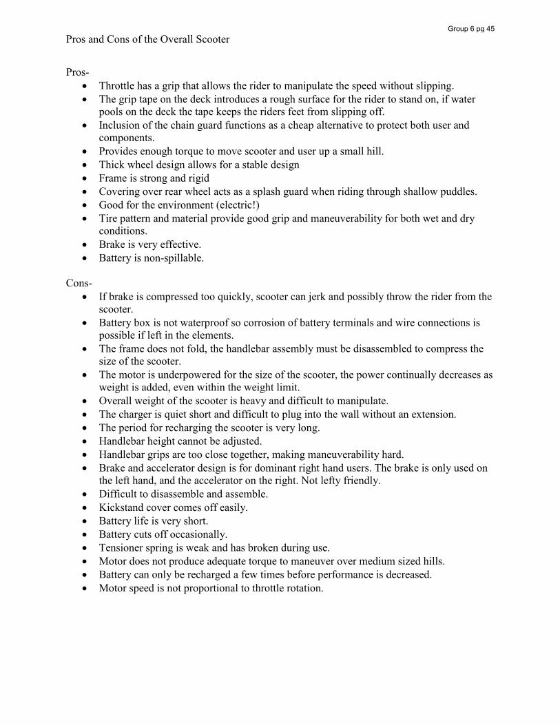
Pros and Cons of the Overall Scooter
Pros- x Throttle has a grip that allows the rider to manipulate the speed without slipping. x The grip tape on the deck introduces a rough surface for the rider to stand on, if water
pools on the deck the tape keeps the riders feet from slipping off. x Inclusion of the chain guard functions as a cheap alternative to protect both user and
components. x Provides enough torque to move scooter and user up a small hill. x Thick wheel design allows for a stable design x Frame is strong and rigid x Covering over rear wheel acts as a splash guard when riding through shallow puddles. x Good for the environment (electric!) x Tire pattern and material provide good grip and maneuverability for both wet and dry
conditions. x Brake is very effective. x Battery is non-spillable.
Cons-
x If brake is compressed too quickly, scooter can jerk and possibly throw the rider from the scooter.
x Battery box is not waterproof so corrosion of battery terminals and wire connections is possible if left in the elements.
x The frame does not fold, the handlebar assembly must be disassembled to compress the size of the scooter.
x The motor is underpowered for the size of the scooter, the power continually decreases as weight is added, even within the weight limit.
x Overall weight of the scooter is heavy and difficult to manipulate. x The charger is quiet short and difficult to plug into the wall without an extension. x The period for recharging the scooter is very long. x Handlebar height cannot be adjusted. x Handlebar grips are too close together, making maneuverability hard. x Brake and accelerator design is for dominant right hand users. The brake is only used on
the left hand, and the accelerator on the right. Not lefty friendly. x Difficult to disassemble and assemble. x Kickstand cover comes off easily. x Battery life is very short. x Battery cuts off occasionally. x Tensioner spring is weak and has broken during use. x Motor does not produce adequate torque to maneuver over medium sized hills. x Battery can only be recharged a few times before performance is decreased. x Motor speed is not proportional to throttle rotation.
Group 6 pg 45
Material Identification
In order to determine what material each component was made of in the scooter, several tests were run and the results were analyzed. For metal parts, a magnet was passed next to the object and if the material was attracted to the magnet, it was assumed that the part was ferrous, some alloy of steel. For parts that were non-metal, a hot soldering iron was pressed against the surface to see if the material flowed or softened. If the material softened it was determined that the material was thermoplastic. All other materials were determined to be thermosets. They were placed in water to determine whether or not they floated. Each material was then burned and observations of the flame were recorded. From these observations, the materials were identified.
Group 6 pg 46
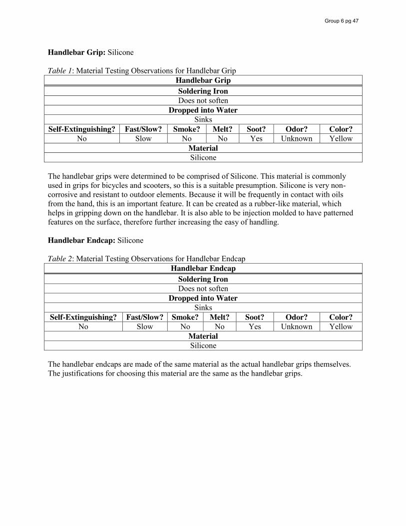
Handlebar Grip: Silicone Table 1: Material Testing Observations for Handlebar Grip
Handlebar Grip Soldering Iron Does not soften
Dropped into Water Sinks
Self-Extinguishing? Fast/Slow? Smoke? Melt? Soot? Odor? Color? No Slow No No Yes Unknown Yellow
Material Silicone
The handlebar grips were determined to be comprised of Silicone. This material is commonly used in grips for bicycles and scooters, so this is a suitable presumption. Silicone is very non-corrosive and resistant to outdoor elements. Because it will be frequently in contact with oils from the hand, this is an important feature. It can be created as a rubber-like material, which helps in gripping down on the handlebar. It is also able to be injection molded to have patterned features on the surface, therefore further increasing the easy of handling. Handlebar Endcap: Silicone Table 2: Material Testing Observations for Handlebar Endcap
Handlebar Endcap Soldering Iron Does not soften
Dropped into Water Sinks
Self-Extinguishing? Fast/Slow? Smoke? Melt? Soot? Odor? Color? No Slow No No Yes Unknown Yellow
Material Silicone
The handlebar endcaps are made of the same material as the actual handlebar grips themselves. The justifications for choosing this material are the same as the handlebar grips.
Group 6 pg 47
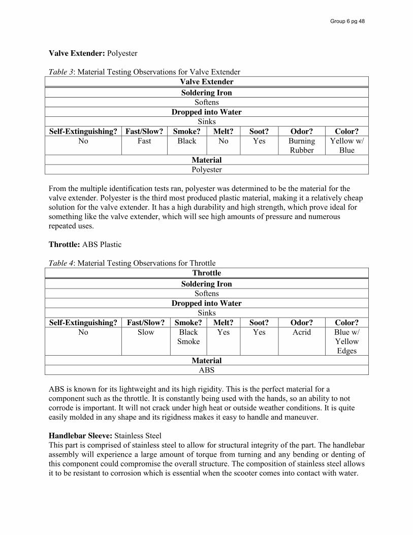
Valve Extender: Polyester Table 3: Material Testing Observations for Valve Extender
Valve Extender Soldering Iron
Softens Dropped into Water
Sinks Self-Extinguishing? Fast/Slow? Smoke? Melt? Soot? Odor? Color?
No Fast Black No Yes Burning Rubber
Yellow w/ Blue
Material Polyester
From the multiple identification tests ran, polyester was determined to be the material for the valve extender. Polyester is the third most produced plastic material, making it a relatively cheap solution for the valve extender. It has a high durability and high strength, which prove ideal for something like the valve extender, which will see high amounts of pressure and numerous repeated uses. Throttle: ABS Plastic Table 4: Material Testing Observations for Throttle
Throttle Soldering Iron
Softens Dropped into Water
Sinks Self-Extinguishing? Fast/Slow? Smoke? Melt? Soot? Odor? Color?
No Slow Black Smoke
Yes Yes Acrid Blue w/ Yellow Edges
Material ABS
ABS is known for its lightweight and its high rigidity. This is the perfect material for a component such as the throttle. It is constantly being used with the hands, so an ability to not corrode is important. It will not crack under high heat or outside weather conditions. It is quite easily molded in any shape and its rigidness makes it easy to handle and maneuver. Handlebar Sleeve: Stainless Steel This part is comprised of stainless steel to allow for structural integrity of the part. The handlebar assembly will experience a large amount of torque from turning and any bending or denting of this component could compromise the overall structure. The composition of stainless steel allows it to be resistant to corrosion which is essential when the scooter comes into contact with water.
Group 6 pg 48
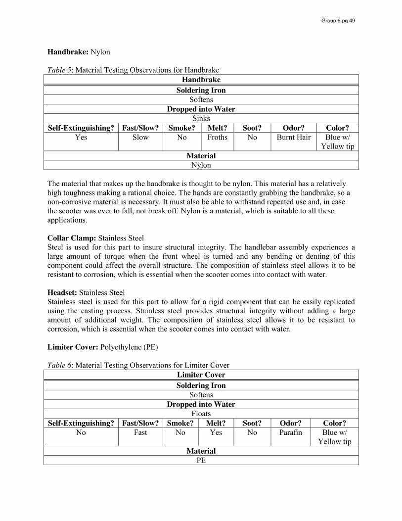
Handbrake: Nylon Table 5: Material Testing Observations for Handbrake
Handbrake Soldering Iron
Softens Dropped into Water
Sinks Self-Extinguishing? Fast/Slow? Smoke? Melt? Soot? Odor? Color?
Yes Slow No Froths No Burnt Hair Blue w/ Yellow tip
Material Nylon
The material that makes up the handbrake is thought to be nylon. This material has a relatively high toughness making a rational choice. The hands are constantly grabbing the handbrake, so a non-corrosive material is necessary. It must also be able to withstand repeated use and, in case the scooter was ever to fall, not break off. Nylon is a material, which is suitable to all these applications. Collar Clamp: Stainless Steel Steel is used for this part to insure structural integrity. The handlebar assembly experiences a large amount of torque when the front wheel is turned and any bending or denting of this component could affect the overall structure. The composition of stainless steel allows it to be resistant to corrosion, which is essential when the scooter comes into contact with water. Headset: Stainless Steel Stainless steel is used for this part to allow for a rigid component that can be easily replicated using the casting process. Stainless steel provides structural integrity without adding a large amount of additional weight. The composition of stainless steel allows it to be resistant to corrosion, which is essential when the scooter comes into contact with water. Limiter Cover: Polyethylene (PE) Table 6: Material Testing Observations for Limiter Cover
Limiter Cover Soldering Iron
Softens Dropped into Water
Floats Self-Extinguishing? Fast/Slow? Smoke? Melt? Soot? Odor? Color?
No Fast No Yes No Parafin Blue w/ Yellow tip
Material PE
Group 6 pg 49
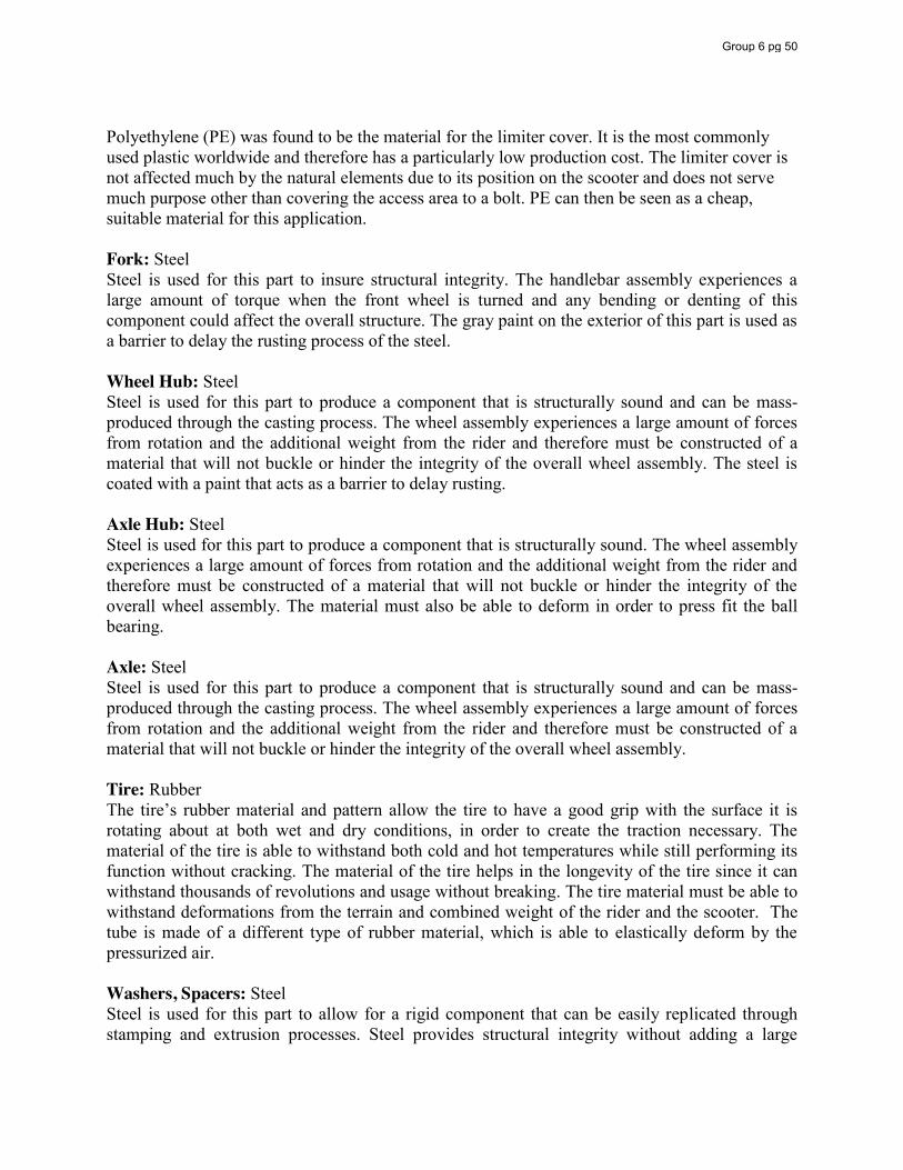
Polyethylene (PE) was found to be the material for the limiter cover. It is the most commonly used plastic worldwide and therefore has a particularly low production cost. The limiter cover is not affected much by the natural elements due to its position on the scooter and does not serve much purpose other than covering the access area to a bolt. PE can then be seen as a cheap, suitable material for this application. Fork: Steel Steel is used for this part to insure structural integrity. The handlebar assembly experiences a large amount of torque when the front wheel is turned and any bending or denting of this component could affect the overall structure. The gray paint on the exterior of this part is used as a barrier to delay the rusting process of the steel. Wheel Hub: Steel Steel is used for this part to produce a component that is structurally sound and can be mass-produced through the casting process. The wheel assembly experiences a large amount of forces from rotation and the additional weight from the rider and therefore must be constructed of a material that will not buckle or hinder the integrity of the overall wheel assembly. The steel is coated with a paint that acts as a barrier to delay rusting. Axle Hub: Steel Steel is used for this part to produce a component that is structurally sound. The wheel assembly experiences a large amount of forces from rotation and the additional weight from the rider and therefore must be constructed of a material that will not buckle or hinder the integrity of the overall wheel assembly. The material must also be able to deform in order to press fit the ball bearing. Axle: Steel Steel is used for this part to produce a component that is structurally sound and can be mass-produced through the casting process. The wheel assembly experiences a large amount of forces from rotation and the additional weight from the rider and therefore must be constructed of a material that will not buckle or hinder the integrity of the overall wheel assembly. Tire: Rubber The tire’s rubber material and pattern allow the tire to have a good grip with the surface it is rotating about at both wet and dry conditions, in order to create the traction necessary. The material of the tire is able to withstand both cold and hot temperatures while still performing its function without cracking. The material of the tire helps in the longevity of the tire since it can withstand thousands of revolutions and usage without breaking. The tire material must be able to withstand deformations from the terrain and combined weight of the rider and the scooter. The tube is made of a different type of rubber material, which is able to elastically deform by the pressurized air. Washers, Spacers: Steel Steel is used for this part to allow for a rigid component that can be easily replicated through stamping and extrusion processes. Steel provides structural integrity without adding a large
Group 6 pg 50
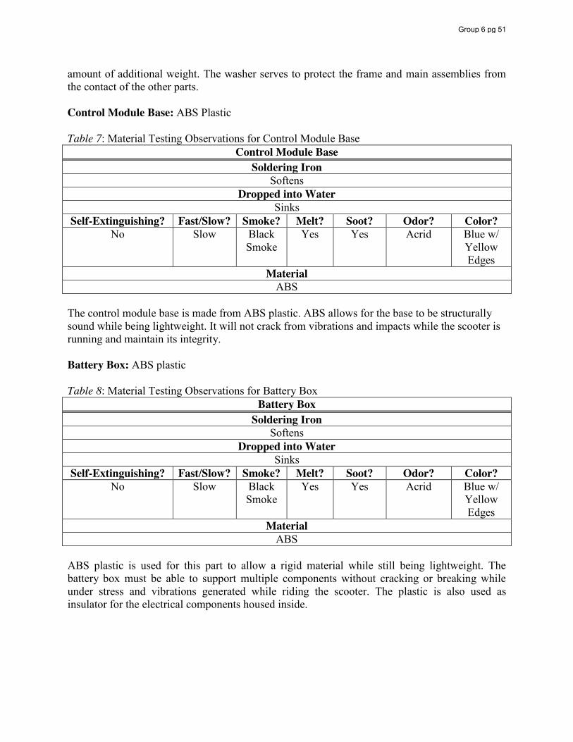
amount of additional weight. The washer serves to protect the frame and main assemblies from the contact of the other parts. Control Module Base: ABS Plastic Table 7: Material Testing Observations for Control Module Base
Control Module Base Soldering Iron
Softens Dropped into Water
Sinks Self-Extinguishing? Fast/Slow? Smoke? Melt? Soot? Odor? Color?
No Slow Black Smoke
Yes Yes Acrid Blue w/ Yellow Edges
Material ABS
The control module base is made from ABS plastic. ABS allows for the base to be structurally sound while being lightweight. It will not crack from vibrations and impacts while the scooter is running and maintain its integrity. Battery Box: ABS plastic Table 8: Material Testing Observations for Battery Box
Battery Box Soldering Iron
Softens Dropped into Water
Sinks Self-Extinguishing? Fast/Slow? Smoke? Melt? Soot? Odor? Color?
No Slow Black Smoke
Yes Yes Acrid Blue w/ Yellow Edges
Material ABS
ABS plastic is used for this part to allow a rigid material while still being lightweight. The battery box must be able to support multiple components without cracking or breaking while under stress and vibrations generated while riding the scooter. The plastic is also used as insulator for the electrical components housed inside.
Group 6 pg 51
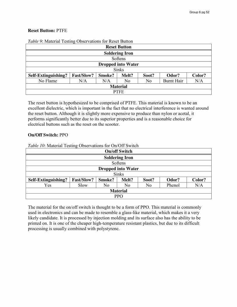
Reset Button: PTFE Table 9: Material Testing Observations for Reset Button
Reset Button Soldering Iron
Softens Dropped into Water
Sinks Self-Extinguishing? Fast/Slow? Smoke? Melt? Soot? Odor? Color?
No Flame N/A N/A No No Burnt Hair N/A Material
PTFE The reset button is hypothesized to be comprised of PTFE. This material is known to be an excellent dielectric, which is important in the fact that no electrical interference is wanted around the reset button. Although it is slightly more expensive to produce than nylon or acetal, it performs significantly better due to its superior properties and is a reasonable choice for electrical buttons such as the reset on the scooter. On/Off Switch: PPO Table 10: Material Testing Observations for On/Off Switch
On/off Switch Soldering Iron
Softens Dropped into Water
Sinks Self-Extinguishing? Fast/Slow? Smoke? Melt? Soot? Odor? Color?
Yes Slow No No No Phenol N/A Material
PPO The material for the on/off switch is thought to be a form of PPO. This material is commonly used in electronics and can be made to resemble a glass-like material, which makes it a very likely candidate. It is processed by injection molding and its surface also has the ability to be printed on. It is one of the cheaper high-temperature resistant plastics, but due to its difficult processing is usually combined with polystyrene.
Group 6 pg 52
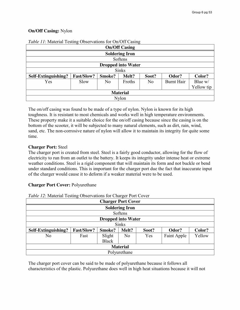
On/Off Casing: Nylon Table 11: Material Testing Observations for On/Off Casing
On/Off Casing Soldering Iron
Softens Dropped into Water
Sinks Self-Extinguishing? Fast/Slow? Smoke? Melt? Soot? Odor? Color?
Yes Slow No Froths No Burnt Hair Blue w/ Yellow tip
Material Nylon
The on/off casing was found to be made of a type of nylon. Nylon is known for its high toughness. It is resistant to most chemicals and works well in high temperature environments. These property make it a suitable choice for the on/off casing because since the casing is on the bottom of the scooter, it will be subjected to many natural elements, such as dirt, rain, wind, sand, etc. The non-corrosive nature of nylon will allow it to maintain its integrity for quite some time. Charger Port: Steel The charger port is created from steel. Steel is a fairly good conductor, allowing for the flow of electricity to run from an outlet to the battery. It keeps its integrity under intense heat or extreme weather conditions. Steel is a rigid component that will maintain its form and not buckle or bend under standard conditions. This is important for the charger port due the fact that inaccurate input of the charger would cause it to deform if a weaker material were to be used. Charger Port Cover: Polyurethane Table 12: Material Testing Observations for Charger Port Cover
Charger Port Cover Soldering Iron
Softens Dropped into Water
Sinks Self-Extinguishing? Fast/Slow? Smoke? Melt? Soot? Odor? Color?
No Fast Slight Black
No Yes Faint Apple Yellow
Material Polyurethane
The charger port cover can be said to be made of polyurethane because it follows all characteristics of the plastic. Polyurethane does well in high heat situations because it will not
Group 6 pg 53
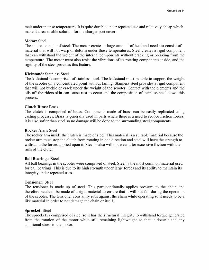
melt under intense temperature. It is quite durable under repeated use and relatively cheap which make it a reasonable solution for the charger port cover. Motor: Steel The motor is made of steel. The motor creates a large amount of heat and needs to consist of a material that will not warp or deform under those temperatures. Steel creates a rigid component that can withstand the weight of the internal components without cracking or breaking from the temperature. The motor must also resist the vibrations of its rotating components inside, and the rigidity of the steel provides this feature. Kickstand: Stainless Steel The kickstand is comprised of stainless steel. The kickstand must be able to support the weight of the scooter on a concentrated point without failing. Stainless steel provides a rigid component that will not buckle or crack under the weight of the scooter. Contact with the elements and the oils off the riders skin can cause rust to occur and the composition of stainless steel slows this process. Clutch Rims: Brass The clutch is comprised of brass. Components made of brass can be easily replicated using casting processes. Brass is generally used in parts where there is a need to reduce friction forces; it is also softer than steel so no damage will be done to the surrounding steel components. Rocker Arm: Steel The rocker arm inside the clutch is made of steel. This material is a suitable material because the rocker arm must stop the clutch from rotating in one direction and steel will have the strength to withstand the forces applied upon it. Steel is also will not wear after excessive friction with the rims of the clutch. Ball Bearings: Steel All ball bearings in the scooter were comprised of steel. Steel is the most common material used for ball bearings. This is due to its high strength under large forces and its ability to maintain its integrity under repeated uses. Tensioner: Steel The tensioner is made up of steel. This part continually applies pressure to the chain and therefore needs to be made of a rigid material to ensure that it will not fail during the operation of the scooter. The tensioner constantly rubs against the chain while operating so it needs to be a like material in order to not damage the chain or itself. Sprocket: Steel The sprocket is comprised of steel so it has the structural integrity to withstand torque generated from the rotation of the motor while still remaining lightweight so that it doesn’t add any additional stress to the motor.
Group 6 pg 54
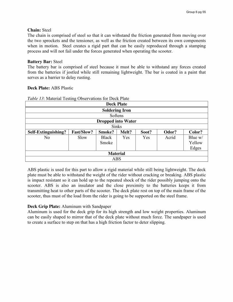
Chain: Steel The chain is comprised of steel so that it can withstand the friction generated from moving over the two sprockets and the tensioner, as well as the friction created between its own components when in motion. Steel creates a rigid part that can be easily reproduced through a stamping process and will not fail under the forces generated when operating the scooter. Battery Bar: Steel The battery bar is comprised of steel because it must be able to withstand any forces created from the batteries if jostled while still remaining lightweight. The bar is coated in a paint that serves as a barrier to delay rusting. Deck Plate: ABS Plastic Table 13: Material Testing Observations for Deck Plate
Deck Plate Soldering Iron
Softens Dropped into Water
Sinks Self-Extinguishing? Fast/Slow? Smoke? Melt? Soot? Odor? Color?
No Slow Black Smoke
Yes Yes Acrid Blue w/ Yellow Edges
Material ABS
ABS plastic is used for this part to allow a rigid material while still being lightweight. The deck plate must be able to withstand the weight of the rider without cracking or breaking. ABS plastic is impact resistant so it can hold up to the repeated shock of the rider possibly jumping onto the scooter. ABS is also an insulator and the close proximity to the batteries keeps it from transmitting heat to other parts of the scooter. The deck plate rest on top of the main frame of the scooter, thus must of the load from the rider is going to be supported on the steel frame. Deck Grip Plate: Aluminum with Sandpaper Aluminum is used for the deck grip for its high strength and low weight properties. Aluminum can be easily shaped to mirror that of the deck plate without much force. The sandpaper is used to create a surface to step on that has a high friction factor to deter slipping.
Group 6 pg 55
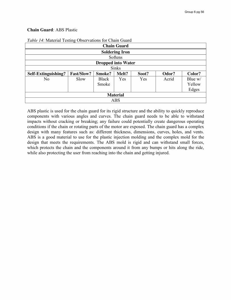
Chain Guard: ABS Plastic Table 14: Material Testing Observations for Chain Guard
Chain Guard Soldering Iron
Softens Dropped into Water
Sinks Self-Extinguishing? Fast/Slow? Smoke? Melt? Soot? Odor? Color?
No Slow Black Smoke
Yes Yes Acrid Blue w/ Yellow Edges
Material ABS
ABS plastic is used for the chain guard for its rigid structure and the ability to quickly reproduce components with various angles and curves. The chain guard needs to be able to withstand impacts without cracking or breaking; any failure could potentially create dangerous operating conditions if the chain or rotating parts of the motor are exposed. The chain guard has a complex design with many features such as: different thickness, dimensions, curves, holes, and vents. ABS is a good material to use for the plastic injection molding and the complex mold for the design that meets the requirements. The ABS mold is rigid and can withstand small forces, which protects the chain and the components around it from any bumps or hits along the ride, while also protecting the user from reaching into the chain and getting injured.
Group 6 pg 56
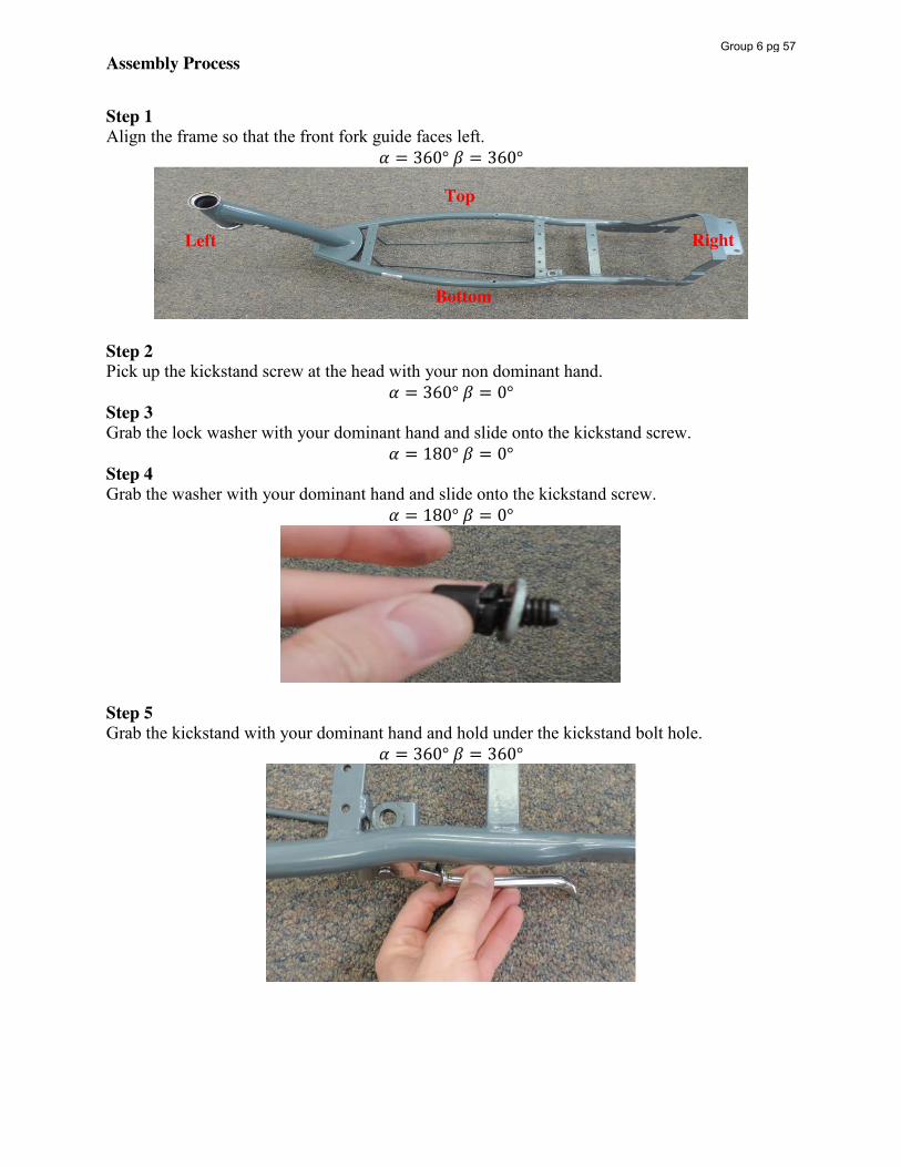
Assembly Process
Step 1 Align the frame so that the front fork guide faces left.
𝛼 = 360° 𝛽 = 360°
Step 2 Pick up the kickstand screw at the head with your non dominant hand.
𝛼 = 360° 𝛽 = 0° Step 3 Grab the lock washer with your dominant hand and slide onto the kickstand screw.
𝛼 = 180° 𝛽 = 0° Step 4 Grab the washer with your dominant hand and slide onto the kickstand screw.
𝛼 = 180° 𝛽 = 0°
Step 5 Grab the kickstand with your dominant hand and hold under the kickstand bolt hole.
𝛼 = 360° 𝛽 = 360°
Left
Top
Bottom
Right
Group 6 pg 57
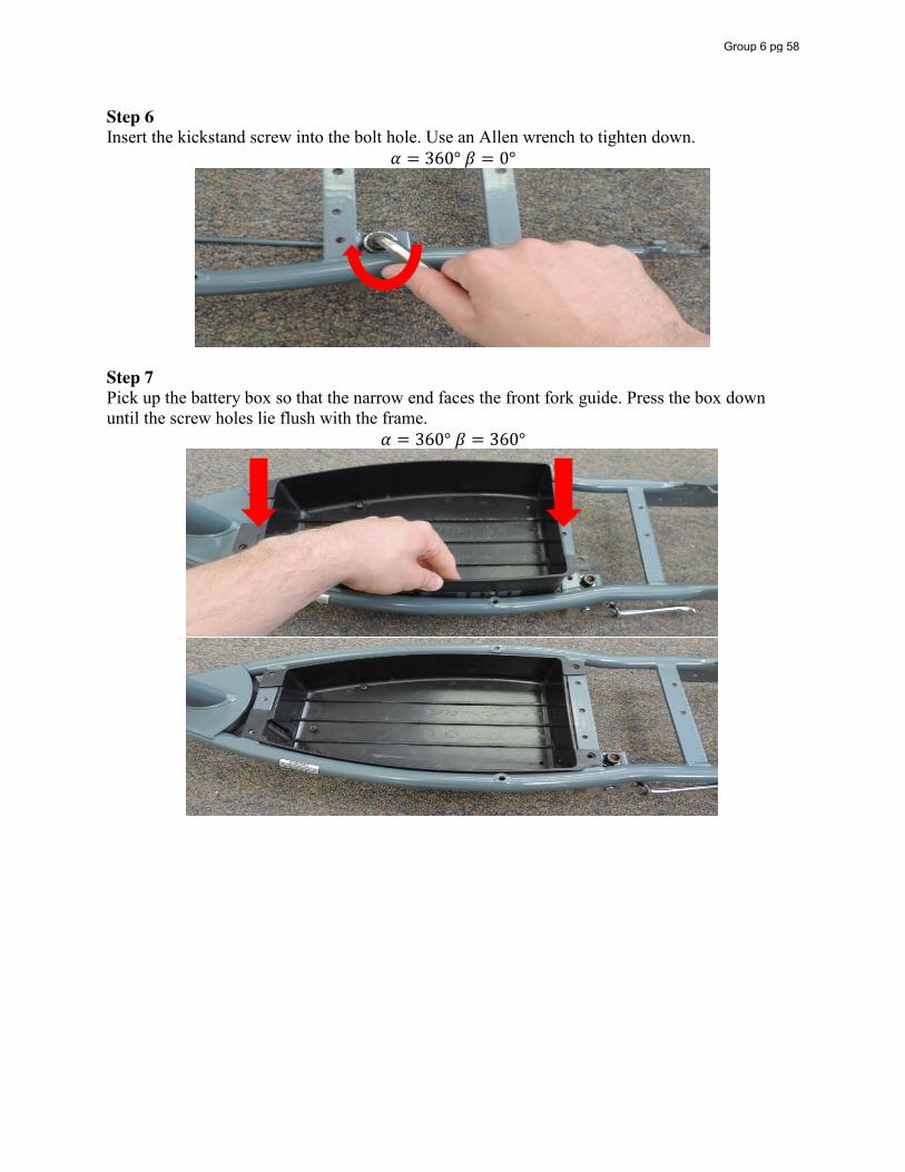
Step 6 Insert the kickstand screw into the bolt hole. Use an Allen wrench to tighten down.
𝛼 = 360° 𝛽 = 0°
Step 7 Pick up the battery box so that the narrow end faces the front fork guide. Press the box down until the screw holes lie flush with the frame.
𝛼 = 360° 𝛽 = 360°
Group 6 pg 58
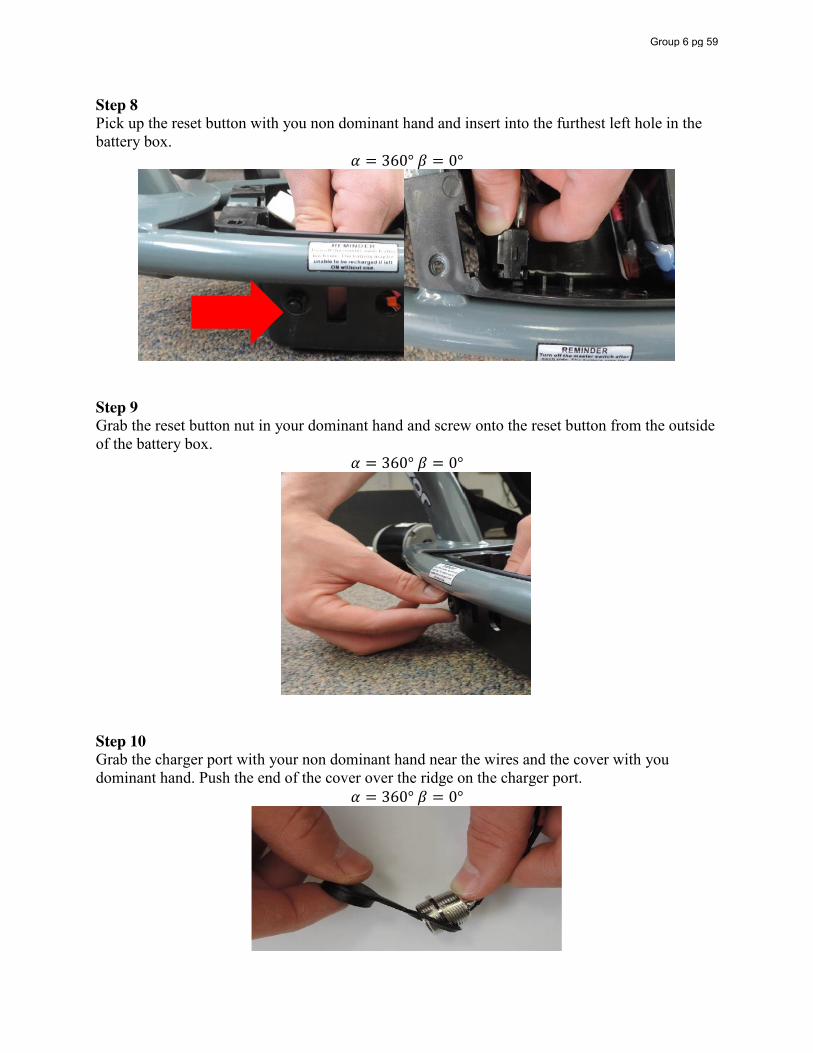
Step 8 Pick up the reset button with you non dominant hand and insert into the furthest left hole in the battery box.
𝛼 = 360° 𝛽 = 0°
Step 9 Grab the reset button nut in your dominant hand and screw onto the reset button from the outside of the battery box.
𝛼 = 360° 𝛽 = 0°
Step 10 Grab the charger port with your non dominant hand near the wires and the cover with you dominant hand. Push the end of the cover over the ridge on the charger port.
𝛼 = 360° 𝛽 = 0°
Group 6 pg 59
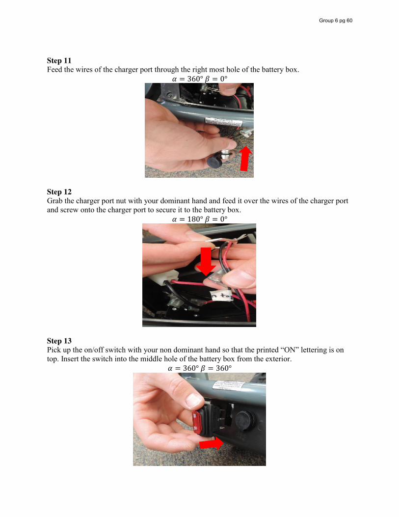
Step 11 Feed the wires of the charger port through the right most hole of the battery box.
𝛼 = 360° 𝛽 = 0°
Step 12 Grab the charger port nut with your dominant hand and feed it over the wires of the charger port and screw onto the charger port to secure it to the battery box.
𝛼 = 180° 𝛽 = 0°
Step 13 Pick up the on/off switch with your non dominant hand so that the printed “ON” lettering is on top. Insert the switch into the middle hole of the battery box from the exterior.
𝛼 = 360° 𝛽 = 360°
Group 6 pg 60
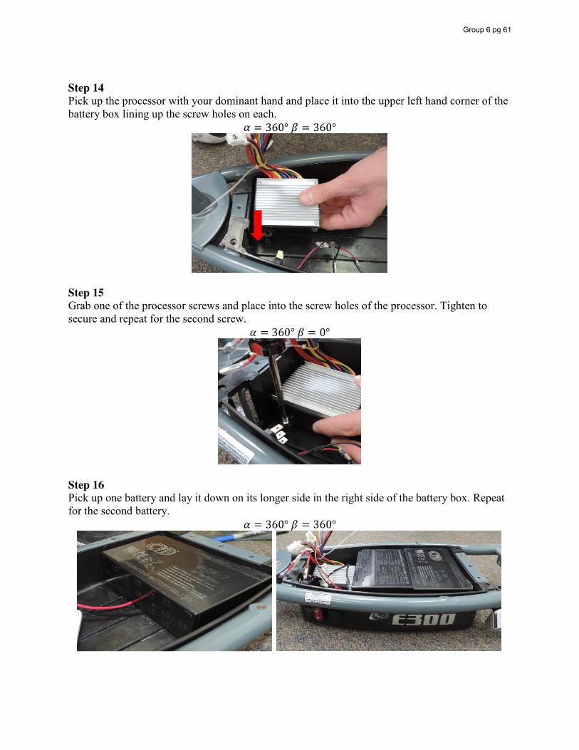
Step 14 Pick up the processor with your dominant hand and place it into the upper left hand corner of the battery box lining up the screw holes on each.
𝛼 = 360° 𝛽 = 360°
Step 15 Grab one of the processor screws and place into the screw holes of the processor. Tighten to secure and repeat for the second screw.
𝛼 = 360° 𝛽 = 0°
Step 16 Pick up one battery and lay it down on its longer side in the right side of the battery box. Repeat for the second battery.
𝛼 = 360° 𝛽 = 360°
Group 6 pg 61
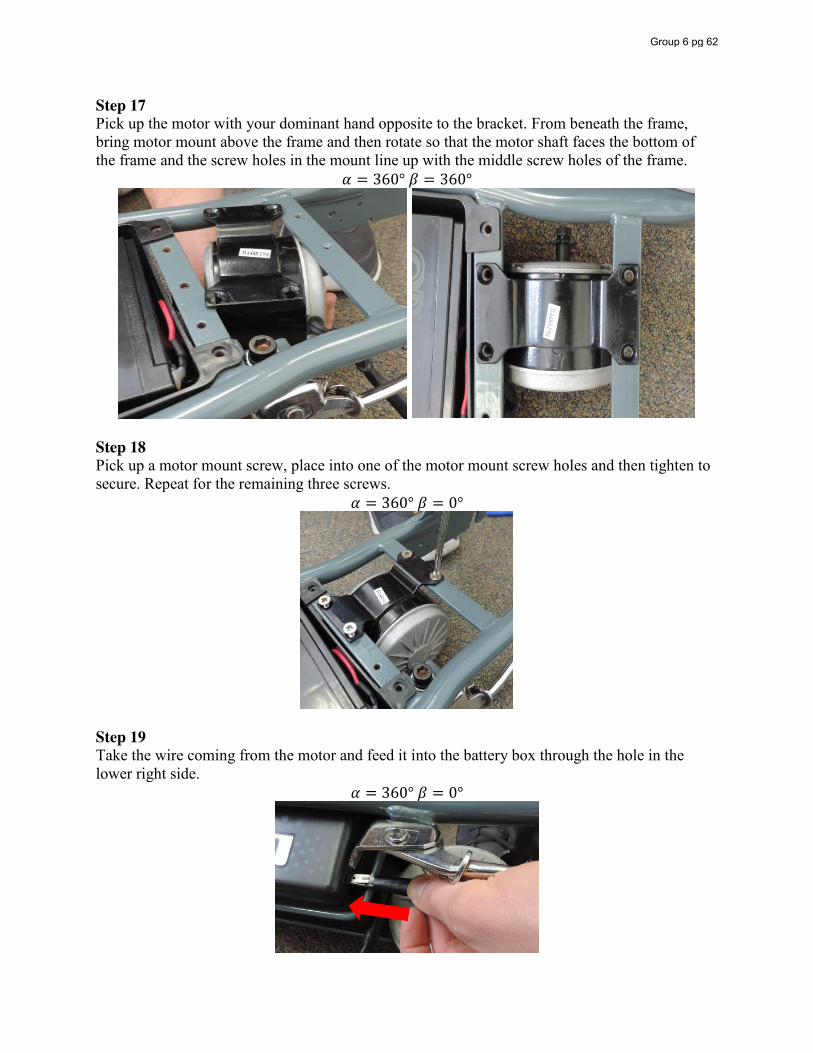
Step 17 Pick up the motor with your dominant hand opposite to the bracket. From beneath the frame, bring motor mount above the frame and then rotate so that the motor shaft faces the bottom of the frame and the screw holes in the mount line up with the middle screw holes of the frame.
𝛼 = 360° 𝛽 = 360°
Step 18 Pick up a motor mount screw, place into one of the motor mount screw holes and then tighten to secure. Repeat for the remaining three screws.
𝛼 = 360° 𝛽 = 0°
Step 19 Take the wire coming from the motor and feed it into the battery box through the hole in the lower right side.
𝛼 = 360° 𝛽 = 0°
Group 6 pg 62
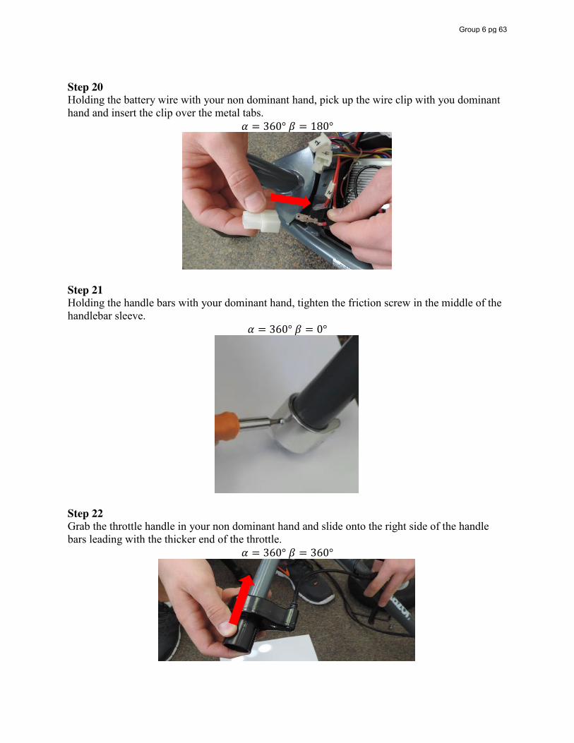
Step 20 Holding the battery wire with your non dominant hand, pick up the wire clip with you dominant hand and insert the clip over the metal tabs.
𝛼 = 360° 𝛽 = 180°
Step 21 Holding the handle bars with your dominant hand, tighten the friction screw in the middle of the handlebar sleeve.
𝛼 = 360° 𝛽 = 0°
Step 22 Grab the throttle handle in your non dominant hand and slide onto the right side of the handle bars leading with the thicker end of the throttle.
𝛼 = 360° 𝛽 = 360°
Group 6 pg 63
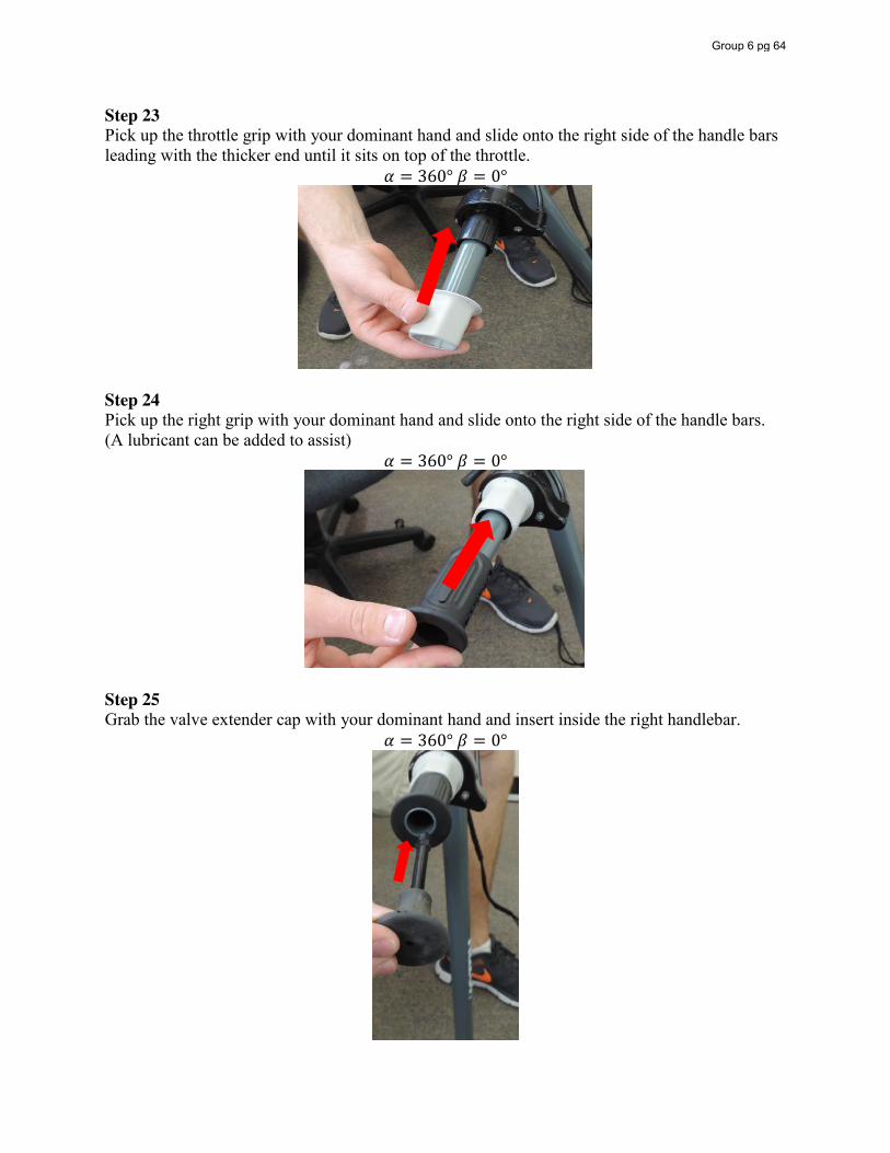
Step 23 Pick up the throttle grip with your dominant hand and slide onto the right side of the handle bars leading with the thicker end until it sits on top of the throttle.
𝛼 = 360° 𝛽 = 0°
Step 24 Pick up the right grip with your dominant hand and slide onto the right side of the handle bars. (A lubricant can be added to assist)
𝛼 = 360° 𝛽 = 0°
Step 25 Grab the valve extender cap with your dominant hand and insert inside the right handlebar.
𝛼 = 360° 𝛽 = 0°
Group 6 pg 64
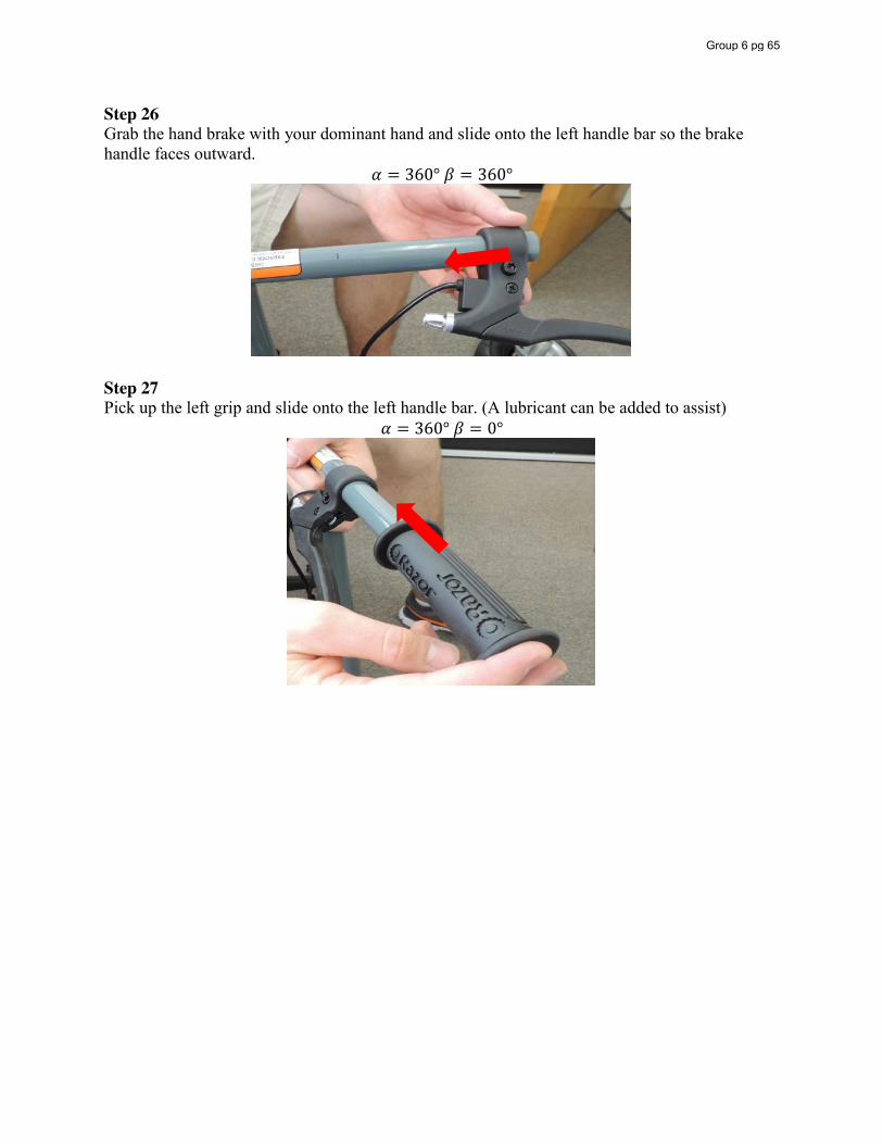
Step 26 Grab the hand brake with your dominant hand and slide onto the left handle bar so the brake handle faces outward.
𝛼 = 360° 𝛽 = 360°
Step 27 Pick up the left grip and slide onto the left handle bar. (A lubricant can be added to assist)
𝛼 = 360° 𝛽 = 0°
Group 6 pg 65
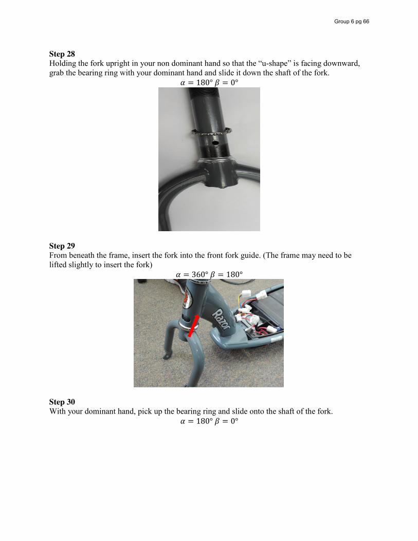
Step 28 Holding the fork upright in your non dominant hand so that the “u-shape” is facing downward, grab the bearing ring with your dominant hand and slide it down the shaft of the fork.
𝛼 = 180° 𝛽 = 0°
Step 29 From beneath the frame, insert the fork into the front fork guide. (The frame may need to be lifted slightly to insert the fork)
𝛼 = 360° 𝛽 = 180°
Step 30 With your dominant hand, pick up the bearing ring and slide onto the shaft of the fork.
𝛼 = 180° 𝛽 = 0°
Group 6 pg 66
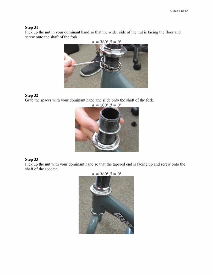
Step 31 Pick up the nut in your dominant hand so that the wider side of the nut is facing the floor and screw onto the shaft of the fork.
𝛼 = 360° 𝛽 = 0°
Step 32 Grab the spacer with your dominant hand and slide onto the shaft of the fork.
𝛼 = 180° 𝛽 = 0°
Step 33 Pick up the nut with your dominant hand so that the tapered end is facing up and screw onto the shaft of the scooter.
𝛼 = 360° 𝛽 = 0°
Group 6 pg 67
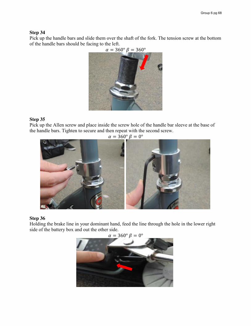
Step 34 Pick up the handle bars and slide them over the shaft of the fork. The tension screw at the bottom of the handle bars should be facing to the left.
𝛼 = 360° 𝛽 = 360°
Step 35 Pick up the Allen screw and place inside the screw hole of the handle bar sleeve at the base of the handle bars. Tighten to secure and then repeat with the second screw.
𝛼 = 360° 𝛽 = 0°
Step 36 Holding the brake line in your dominant hand, feed the line through the hole in the lower right side of the battery box and out the other side.
𝛼 = 360° 𝛽 = 0°
Group 6 pg 68
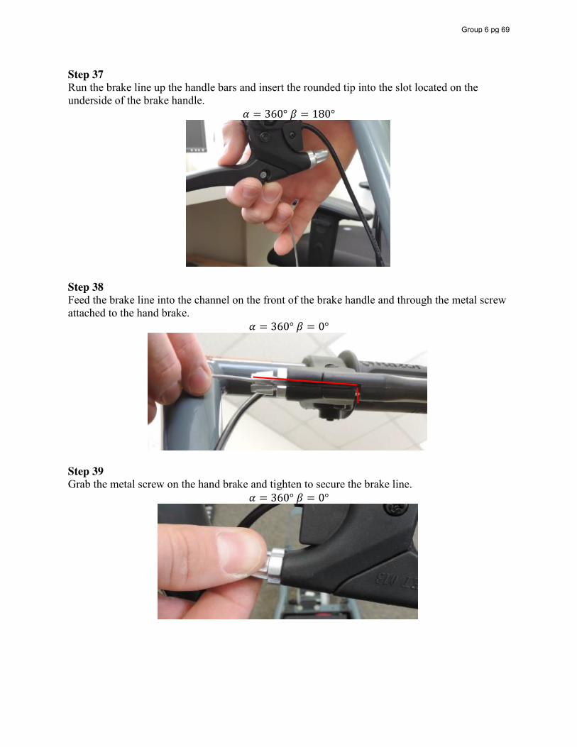
Step 37 Run the brake line up the handle bars and insert the rounded tip into the slot located on the underside of the brake handle.
𝛼 = 360° 𝛽 = 180°
Step 38 Feed the brake line into the channel on the front of the brake handle and through the metal screw attached to the hand brake.
𝛼 = 360° 𝛽 = 0°
Step 39 Grab the metal screw on the hand brake and tighten to secure the brake line.
𝛼 = 360° 𝛽 = 0°
Group 6 pg 69
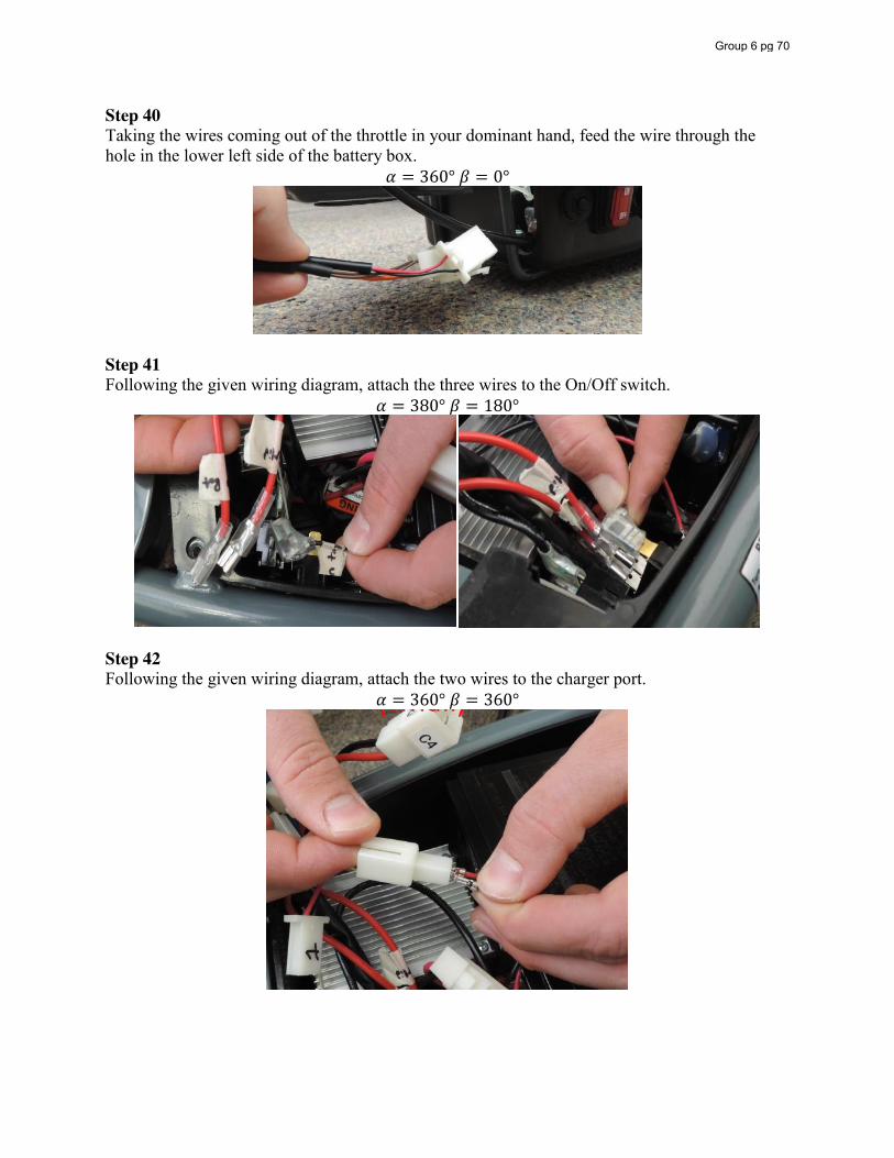
Step 40 Taking the wires coming out of the throttle in your dominant hand, feed the wire through the hole in the lower left side of the battery box.
𝛼 = 360° 𝛽 = 0°
Step 41 Following the given wiring diagram, attach the three wires to the On/Off switch.
𝛼 = 380° 𝛽 = 180°
Step 42 Following the given wiring diagram, attach the two wires to the charger port.
𝛼 = 360° 𝛽 = 360°
Group 6 pg 70
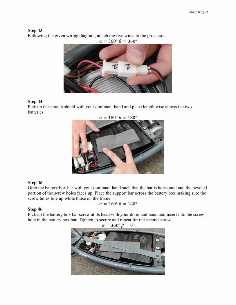
Step 43 Following the given wiring diagram, attach the five wires to the processor.
𝛼 = 360° 𝛽 = 360°
Step 44 Pick up the scratch shield with your dominant hand and place length wise across the two batteries.
𝛼 = 180° 𝛽 = 180°
Step 45 Grab the battery box bar with your dominant hand such that the bar is horizontal and the beveled portion of the screw holes faces up. Place the support bar across the battery box making sure the screw holes line up while those on the frame.
𝛼 = 360° 𝛽 = 180° Step 46 Pick up the battery box bar screw at its head with your dominant hand and insert into the screw hole in the battery box bar. Tighten to secure and repeat for the second screw.
𝛼 = 360° 𝛽 = 0°
Group 6 pg 71
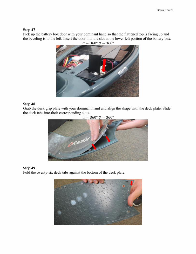
Step 47 Pick up the battery box door with your dominant hand so that the flattened top is facing up and the beveling is to the left. Insert the door into the slot at the lower left portion of the battery box.
𝛼 = 360° 𝛽 = 360°
Step 48 Grab the deck grip plate with your dominant hand and align the shape with the deck plate. Slide the deck tabs into their corresponding slots.
𝛼 = 360° 𝛽 = 360°
Step 49 Fold the twenty-six deck tabs against the bottom of the deck plate.
Group 6 pg 72
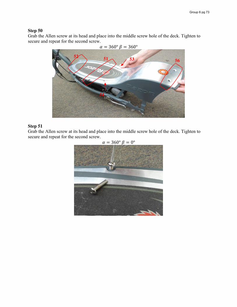
Step 50 Grab the Allen screw at its head and place into the middle screw hole of the deck. Tighten to secure and repeat for the second screw.
𝛼 = 360° 𝛽 = 360°
Step 51 Grab the Allen screw at its head and place into the middle screw hole of the deck. Tighten to secure and repeat for the second screw.
𝛼 = 360° 𝛽 = 0°
51 52 53
54
56
Group 6 pg 73
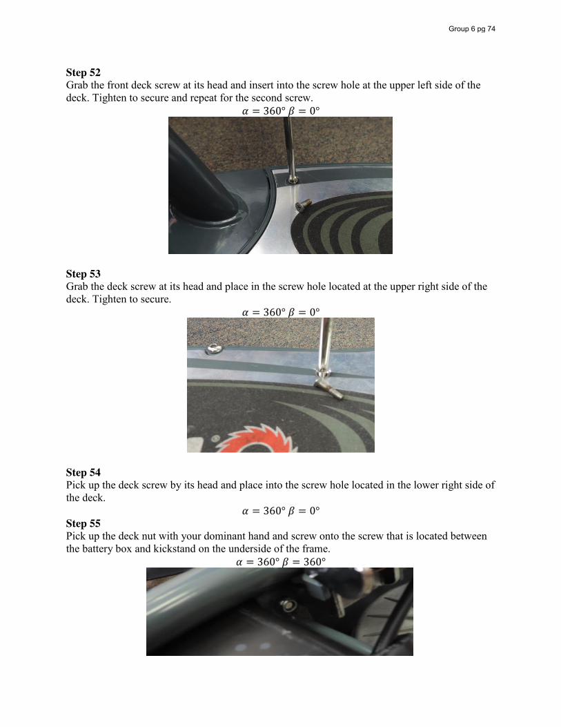
Step 52 Grab the front deck screw at its head and insert into the screw hole at the upper left side of the deck. Tighten to secure and repeat for the second screw.
𝛼 = 360° 𝛽 = 0°
Step 53 Grab the deck screw at its head and place in the screw hole located at the upper right side of the deck. Tighten to secure.
𝛼 = 360° 𝛽 = 0°
Step 54 Pick up the deck screw by its head and place into the screw hole located in the lower right side of the deck.
𝛼 = 360° 𝛽 = 0° Step 55 Pick up the deck nut with your dominant hand and screw onto the screw that is located between the battery box and kickstand on the underside of the frame.
𝛼 = 360° 𝛽 = 360°
Group 6 pg 74
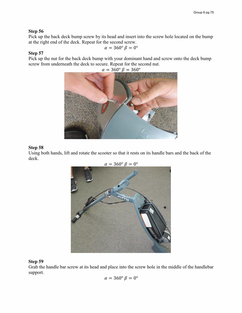
Step 56 Pick up the back deck bump screw by its head and insert into the screw hole located on the bump at the right end of the deck. Repeat for the second screw.
𝛼 = 360° 𝛽 = 0° Step 57 Pick up the nut for the back deck bump with your dominant hand and screw onto the deck bump screw from underneath the deck to secure. Repeat for the second nut.
𝛼 = 360° 𝛽 = 360°
Step 58 Using both hands, lift and rotate the scooter so that it rests on its handle bars and the back of the deck.
𝛼 = 360° 𝛽 = 0°
Step 59 Grab the handle bar screw at its head and place into the screw hole in the middle of the handlebar support.
𝛼 = 360° 𝛽 = 0°
Group 6 pg 75
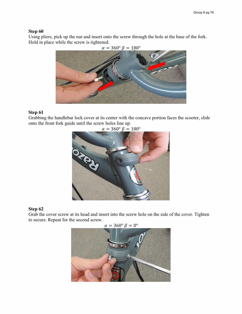
Step 60 Using pliers, pick up the nut and insert onto the screw through the hole at the base of the fork. Hold in place while the screw is tightened.
𝛼 = 360° 𝛽 = 180°
Step 61 Grabbing the handlebar lock cover at its center with the concave portion faces the scooter, slide onto the front fork guide until the screw holes line up.
𝛼 = 360° 𝛽 = 180°
Step 62 Grab the cover screw at its head and insert into the screw hole on the side of the cover. Tighten to secure. Repeat for the second screw.
𝛼 = 360° 𝛽 = 0°
Group 6 pg 76
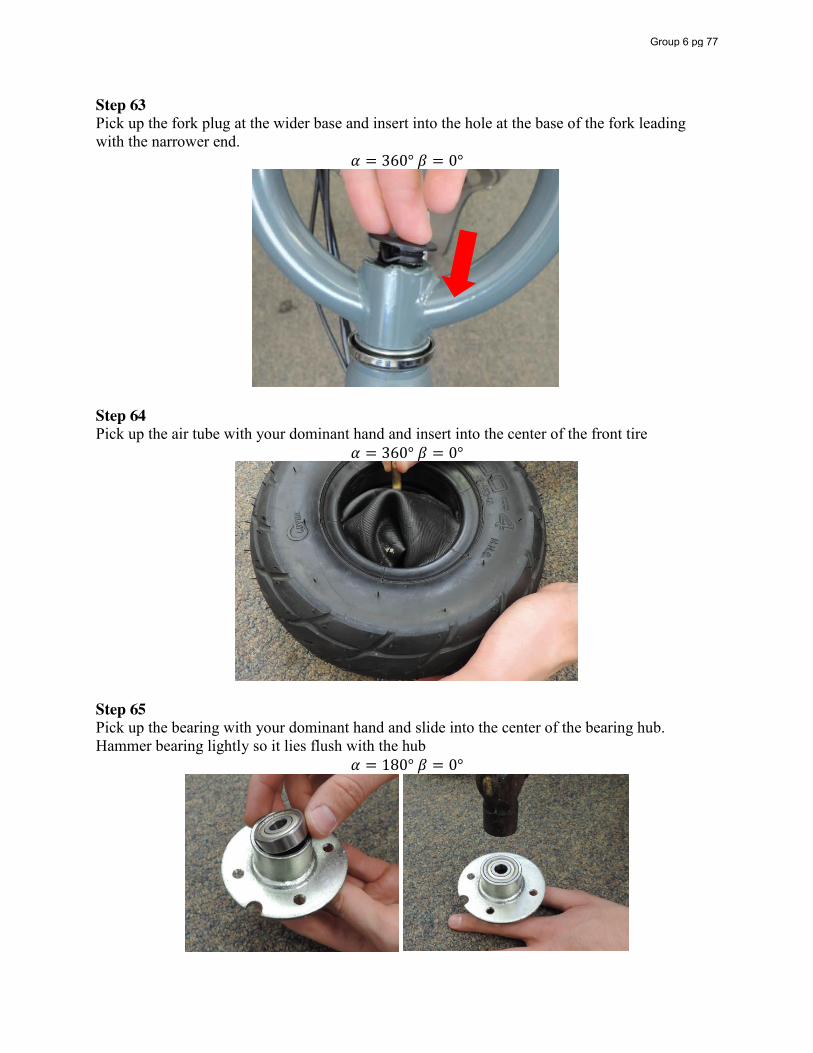
Step 63 Pick up the fork plug at the wider base and insert into the hole at the base of the fork leading with the narrower end.
𝛼 = 360° 𝛽 = 0°
Step 64 Pick up the air tube with your dominant hand and insert into the center of the front tire
𝛼 = 360° 𝛽 = 0°
Step 65 Pick up the bearing with your dominant hand and slide into the center of the bearing hub. Hammer bearing lightly so it lies flush with the hub
𝛼 = 180° 𝛽 = 0°
Group 6 pg 77
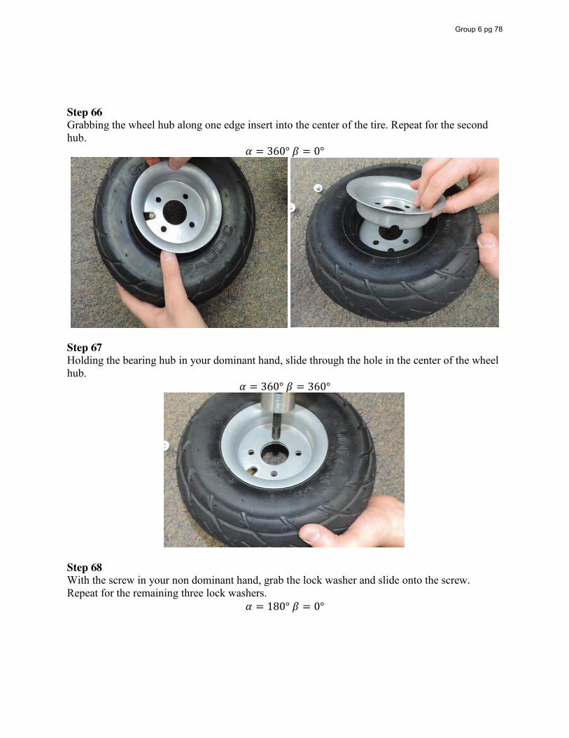
Step 66 Grabbing the wheel hub along one edge insert into the center of the tire. Repeat for the second hub.
𝛼 = 360° 𝛽 = 0°
Step 67 Holding the bearing hub in your dominant hand, slide through the hole in the center of the wheel hub.
𝛼 = 360° 𝛽 = 360°
Step 68 With the screw in your non dominant hand, grab the lock washer and slide onto the screw. Repeat for the remaining three lock washers.
𝛼 = 180° 𝛽 = 0°
Group 6 pg 78
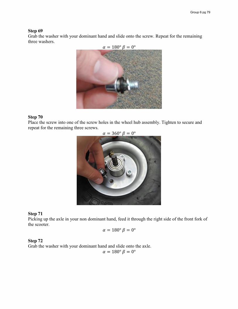
Step 69 Grab the washer with your dominant hand and slide onto the screw. Repeat for the remaining three washers.
𝛼 = 180° 𝛽 = 0°
Step 70 Place the screw into one of the screw holes in the wheel hub assembly. Tighten to secure and repeat for the remaining three screws.
𝛼 = 360° 𝛽 = 0°
Step 71 Picking up the axle in your non dominant hand, feed it through the right side of the front fork of the scooter.
𝛼 = 180° 𝛽 = 0° Step 72 Grab the washer with your dominant hand and slide onto the axle.
𝛼 = 180° 𝛽 = 0°
Group 6 pg 79
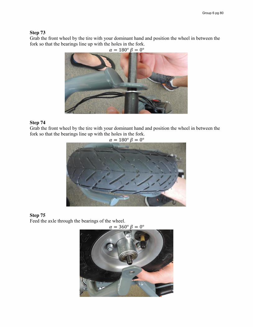
Step 73 Grab the front wheel by the tire with your dominant hand and position the wheel in between the fork so that the bearings line up with the holes in the fork.
𝛼 = 180° 𝛽 = 0°
Step 74 Grab the front wheel by the tire with your dominant hand and position the wheel in between the fork so that the bearings line up with the holes in the fork.
𝛼 = 180° 𝛽 = 0°
Step 75 Feed the axle through the bearings of the wheel.
𝛼 = 360° 𝛽 = 0°
Group 6 pg 80
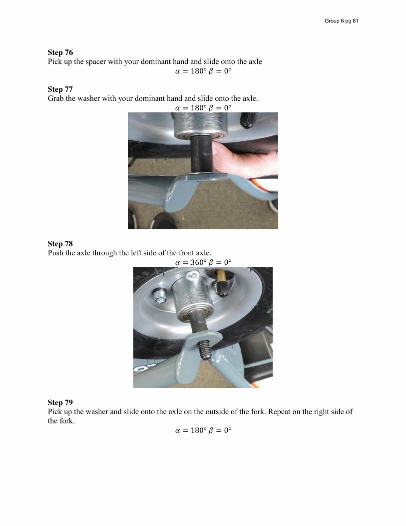
Step 76 Pick up the spacer with your dominant hand and slide onto the axle
𝛼 = 180° 𝛽 = 0° Step 77 Grab the washer with your dominant hand and slide onto the axle.
𝛼 = 180° 𝛽 = 0°
Step 78 Push the axle through the left side of the front axle.
𝛼 = 360° 𝛽 = 0°
Step 79 Pick up the washer and slide onto the axle on the outside of the fork. Repeat on the right side of the fork.
𝛼 = 180° 𝛽 = 0°
Group 6 pg 81
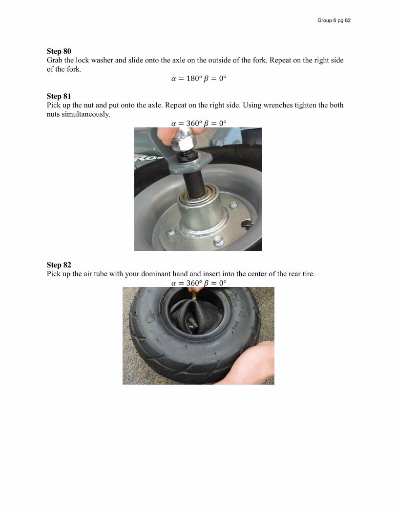
Step 80 Grab the lock washer and slide onto the axle on the outside of the fork. Repeat on the right side of the fork.
𝛼 = 180° 𝛽 = 0° Step 81 Pick up the nut and put onto the axle. Repeat on the right side. Using wrenches tighten the both nuts simultaneously.
𝛼 = 360° 𝛽 = 0°
Step 82 Pick up the air tube with your dominant hand and insert into the center of the rear tire.
𝛼 = 360° 𝛽 = 0°
Group 6 pg 82
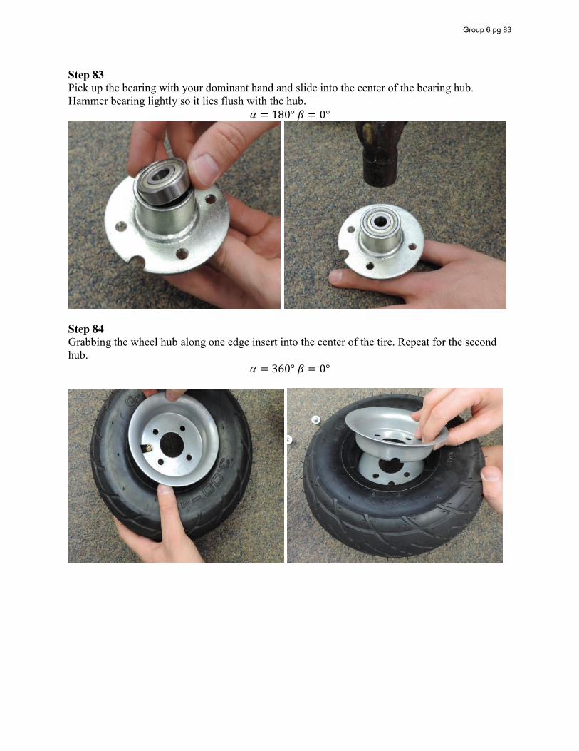
Step 83 Pick up the bearing with your dominant hand and slide into the center of the bearing hub. Hammer bearing lightly so it lies flush with the hub.
𝛼 = 180° 𝛽 = 0°
Step 84 Grabbing the wheel hub along one edge insert into the center of the tire. Repeat for the second hub.
𝛼 = 360° 𝛽 = 0°
Group 6 pg 83
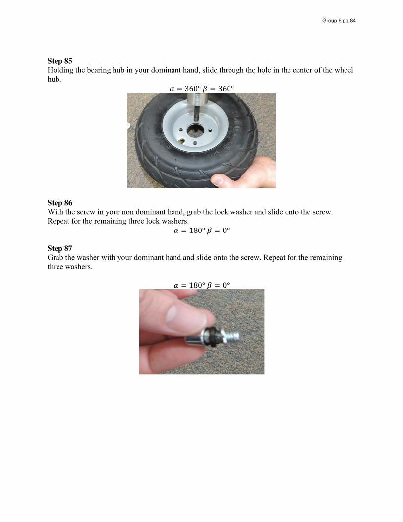
Step 85 Holding the bearing hub in your dominant hand, slide through the hole in the center of the wheel hub.
𝛼 = 360° 𝛽 = 360°
Step 86 With the screw in your non dominant hand, grab the lock washer and slide onto the screw. Repeat for the remaining three lock washers.
𝛼 = 180° 𝛽 = 0° Step 87 Grab the washer with your dominant hand and slide onto the screw. Repeat for the remaining three washers.
𝛼 = 180° 𝛽 = 0°
Group 6 pg 84
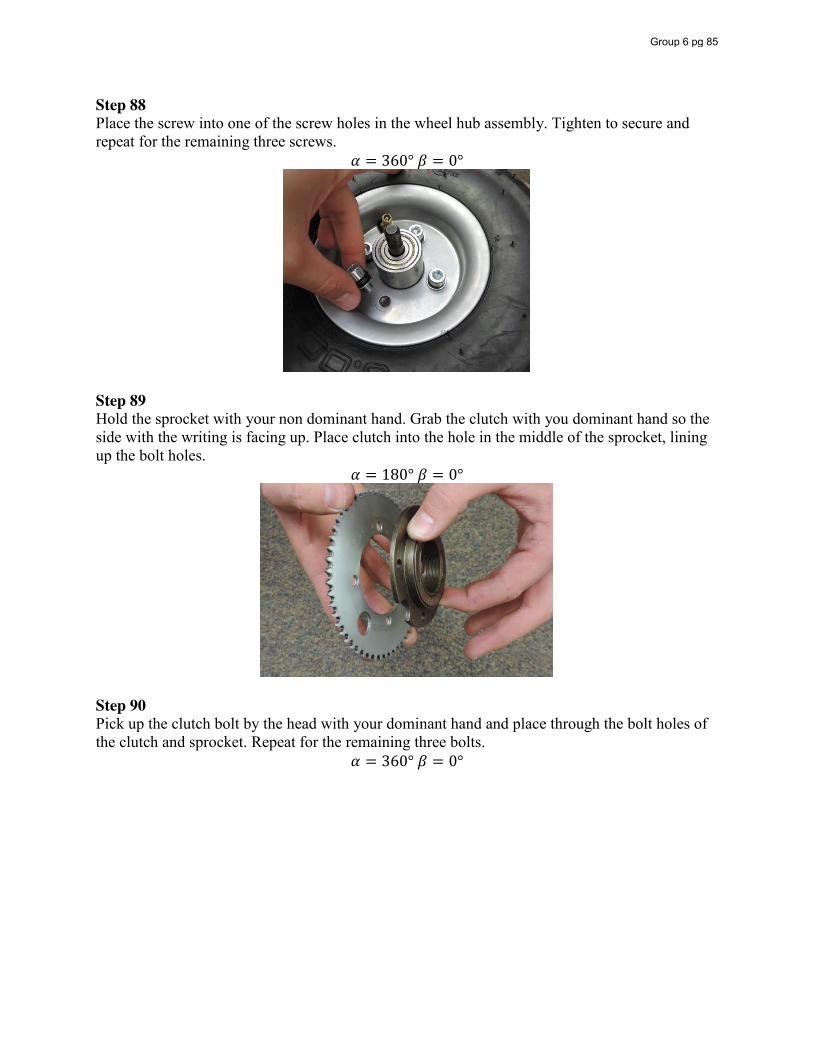
Step 88 Place the screw into one of the screw holes in the wheel hub assembly. Tighten to secure and repeat for the remaining three screws.
𝛼 = 360° 𝛽 = 0°
Step 89 Hold the sprocket with your non dominant hand. Grab the clutch with you dominant hand so the side with the writing is facing up. Place clutch into the hole in the middle of the sprocket, lining up the bolt holes.
𝛼 = 180° 𝛽 = 0°
Step 90 Pick up the clutch bolt by the head with your dominant hand and place through the bolt holes of the clutch and sprocket. Repeat for the remaining three bolts.
𝛼 = 360° 𝛽 = 0°
Group 6 pg 85
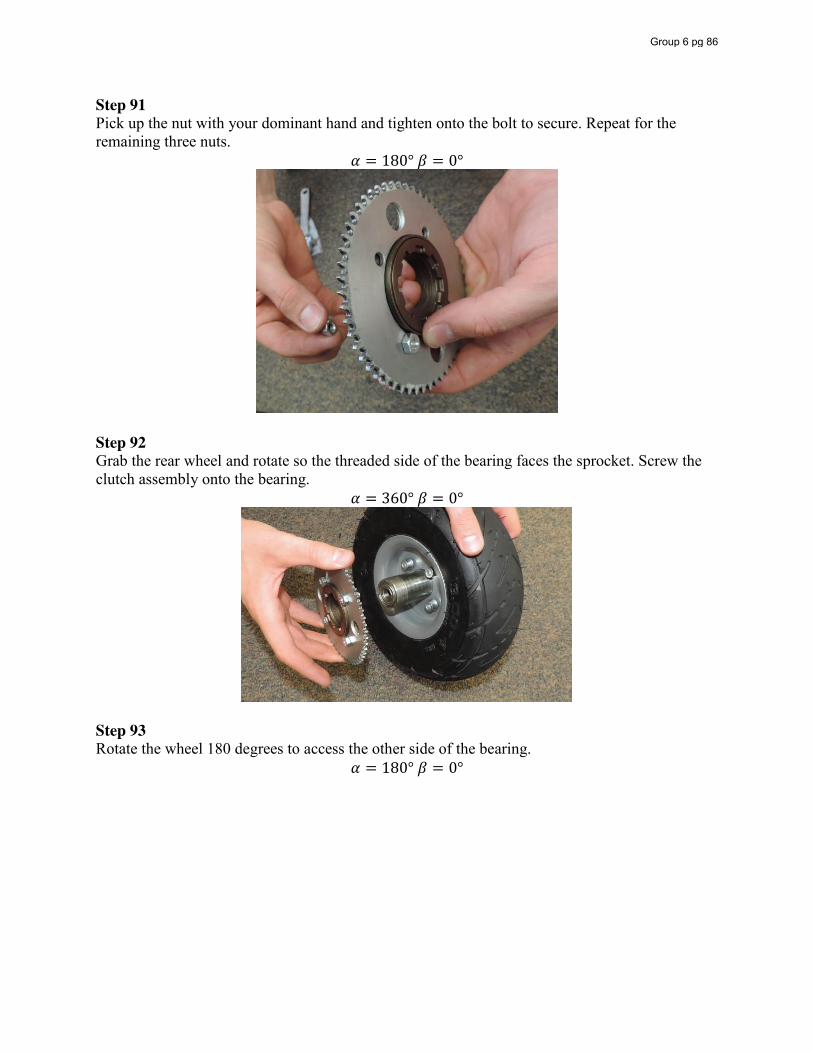
Step 91 Pick up the nut with your dominant hand and tighten onto the bolt to secure. Repeat for the remaining three nuts.
𝛼 = 180° 𝛽 = 0°
Step 92 Grab the rear wheel and rotate so the threaded side of the bearing faces the sprocket. Screw the clutch assembly onto the bearing.
𝛼 = 360° 𝛽 = 0°
Step 93 Rotate the wheel 180 degrees to access the other side of the bearing.
𝛼 = 180° 𝛽 = 0°
Group 6 pg 86
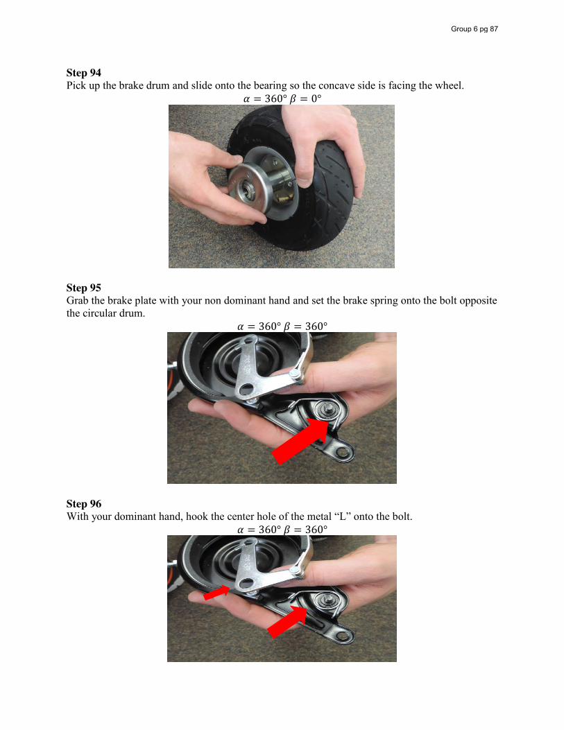
Step 94 Pick up the brake drum and slide onto the bearing so the concave side is facing the wheel.
𝛼 = 360° 𝛽 = 0°
Step 95 Grab the brake plate with your non dominant hand and set the brake spring onto the bolt opposite the circular drum.
𝛼 = 360° 𝛽 = 360°
Step 96 With your dominant hand, hook the center hole of the metal “L” onto the bolt.
𝛼 = 360° 𝛽 = 360°
Group 6 pg 87
Step 97 Pick up the chain with your dominant hand and drag it over the sprocket of the rear wheel.
𝛼 = 180° 𝛽 = 0° Step 98 Pick up the axle with your dominant hand and slide through the left side of the rear fork.
𝛼 = 180° 𝛽 = 0° Step 99 Grab the thin washer with your non dominant hand and slide onto the axle.
𝛼 = 180° 𝛽 = 0° Step 100 Grab the brake plate with your non dominant hand and side the axle through the center of the brake plate. The side containing the spring should face the wheel.
𝛼 = 360° 𝛽 = 360° Step 101 Grab the spacer with your non dominant hand and slide onto the axle.
𝛼 = 180° 𝛽 = 0° Step 102 Grab the rear wheel with your non dominant hand so that the side of the rear wheel containing the brake drum faces the left side of the frame and hold it between the rear fork.
𝛼 = 360° 𝛽 = 0° Step 103 Slide the axle through the rear wheel.
𝛼 = 360° 𝛽 = 0° Step 104 Grab the spacer with your non dominant hand and slide onto the axle.
𝛼 = 180° 𝛽 = 0° Step 105 Grab the thin washer with your non dominant hand and slide onto the axle.
𝛼 = 180° 𝛽 = 0° Step 106 Slide axle through the right side of the frame.
𝛼 = 360° 𝛽 = 0° Step 107 Grab the thick washer with your non dominant hand and slide onto the axle. Repeat on the opposite side.
𝛼 = 180° 𝛽 = 0° Step 108 Grab the lock washer with your non dominant hand and slide onto the axle. Repeat on the opposite side.
𝛼 = 180° 𝛽 = 0° Step 109 Grab the nut with your non dominant hand and put onto the axle. Repeat on the opposite side. Tighten simultaneously to secure.
𝛼 = 360° 𝛽 = 0°
Group 6 pg 88
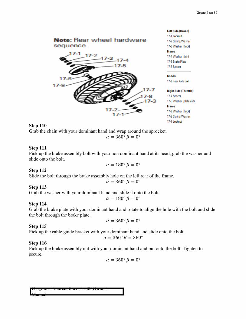
Step 110 Grab the chain with your dominant hand and wrap around the sprocket.
𝛼 = 360° 𝛽 = 0° Step 111 Pick up the brake assembly bolt with your non dominant hand at its head, grab the washer and slide onto the bolt.
𝛼 = 180° 𝛽 = 0° Step 112 Slide the bolt through the brake assembly hole on the left rear of the frame.
𝛼 = 360° 𝛽 = 0° Step 113 Grab the washer with your dominant hand and slide it onto the bolt.
𝛼 = 180° 𝛽 = 0° Step 114 Grab the brake plate with your dominant hand and rotate to align the hole with the bolt and slide the bolt through the brake plate.
𝛼 = 360° 𝛽 = 0° Step 115 Pick up the cable guide bracket with your dominant hand and slide onto the bolt.
𝛼 = 360° 𝛽 = 360° Step 116 Pick up the brake assembly nut with your dominant hand and put onto the bolt. Tighten to secure.
𝛼 = 360° 𝛽 = 0°
Group 6 pg 89
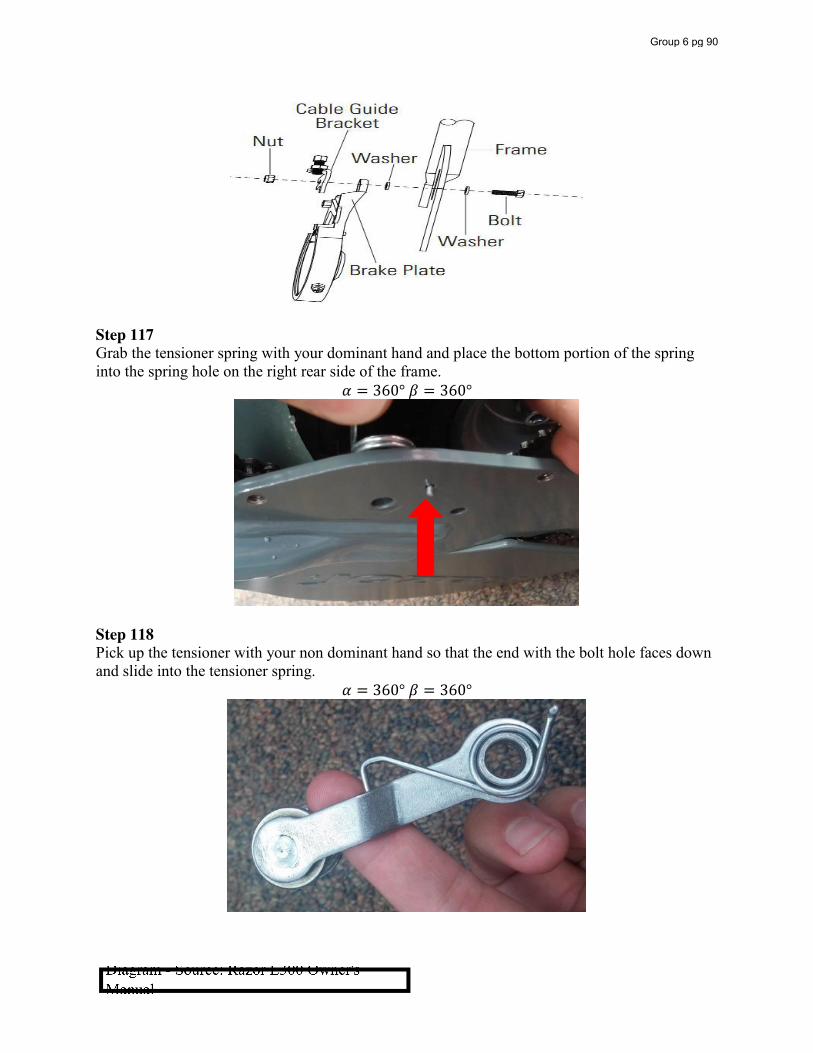
Step 117 Grab the tensioner spring with your dominant hand and place the bottom portion of the spring into the spring hole on the right rear side of the frame.
𝛼 = 360° 𝛽 = 360°
Step 118 Pick up the tensioner with your non dominant hand so that the end with the bolt hole faces down and slide into the tensioner spring.
𝛼 = 360° 𝛽 = 360°
Group 6 pg 90
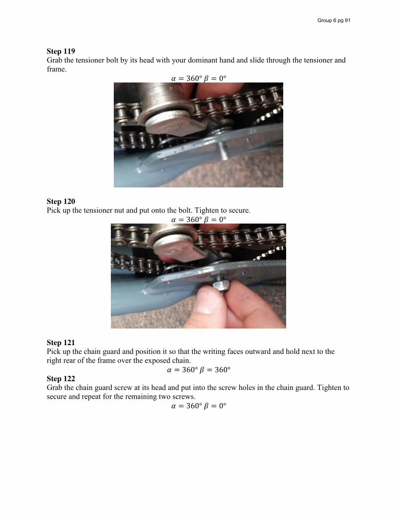
Step 119 Grab the tensioner bolt by its head with your dominant hand and slide through the tensioner and frame.
𝛼 = 360° 𝛽 = 0°
Step 120 Pick up the tensioner nut and put onto the bolt. Tighten to secure.
𝛼 = 360° 𝛽 = 0°
Step 121 Pick up the chain guard and position it so that the writing faces outward and hold next to the right rear of the frame over the exposed chain.
𝛼 = 360° 𝛽 = 360° Step 122 Grab the chain guard screw at its head and put into the screw holes in the chain guard. Tighten to secure and repeat for the remaining two screws.
𝛼 = 360° 𝛽 = 0°
Group 6 pg 91

Table 15: Handling and Insertion Times
Handling Insertion Step Alpha Beta Alpha+
Beta # of
Occurrences Handling
Time Step Time
Source # of Occurrences
Insertion Time
Step Time
Source
1 360 360 720 1 1.95 1.95 3,0 1 - - - 2 360 0 360 1 1.8 1.8 1,1 1 1.5 1.5 0,0 3 180 0 180 1 1.43 1.43 1,0 1 1.5 1.5 0,0 4 180 0 180 1 1.43 1.43 1,0 1 1.5 1.5 0,0 5 360 360 720 1 1.95 1.95 3,0 1 1.5 1.5 0,0 6 360 0 360 1 1.8 1.8 1,1 1 6 6 3,8 7 360 360 720 1 1.95 1.95 3,0 1 4 4 3,0 8 360 0 360 1 1.5 1.5 1,0 1 1.5 1.5 0,0 9 360 0 360 1 1.8 1.8 1,1 1 6 6 3,8 10 360 0 360 1 1.8 1.8 1,1 1 2 2 3,0 11 360 0 360 1 1.5 1.5 1,0 1 1.5 1.5 0,0 12 180 0 180 1 1.5 1.5 1,0 1 6 6 3,8 13 360 360 720 1 1.95 1.95 3,0 1 2 2 3,0 14 360 360 720 1 1.95 1.95 3,0 1 1.5 1.5 0,0 15 360 0 360 2 1.5 3 1,0 2 6 12 3,8 16 360 360 720 2 1.95 3.9 3,0 2 2 4 3,0 17 360 360 720 1 1.95 1.95 3,0 1 5 5 1,2 18 360 0 360 4 1.5 6 1,0 4 6 24 3,8 19 360 0 360 1 1.5 1.5 1,0 1 9 9 9,8 20 360 180 540 1 1.8 1.8 2,0 1 2 2 3,0 21 360 0 360 1 1.8 1.8 1,1 1 6 6 3,8 22 360 360 720 1 1.95 1.95 3,0 1 2 2 3,0 23 360 0 360 1 1.5 1.5 1,0 1 2 2 3,0 24 360 0 360 1 1.5 1.5 1,0 1 5 5 3,1 25 360 0 360 1 1.5 1.5 1,0 1 2 2 3,0 26 360 360 720 1 1.95 1.95 3,0 1 2 2 3,0 27 360 0 360 1 1.5 1.5 1,0 1 5 5 3,1 28 180 0 180 1 1.13 1.13 0,0 1 1.5 1.5 0,0 29 360 180 540 1 1.8 1.8 2,0 1 4 4 1,0 30 180 0 180 1 1.13 1.13 0,0 1 1.5 1.5 0,0 31 360 0 360 1 1.5 1.5 1,0 1 6 6 3,8 32 180 0 180 1 1.13 1.13 0,0 1 1.5 1.5 0,0 33 360 0 360 1 1.5 1.5 1,0 1 6 6 3,8 34 360 360 720 1 1.95 1.95 3,0 1 1.5 1.5 0,0 35 360 0 360 2 1.5 3 1,0 2 6 12 3,8 36 360 0 360 1 1.5 1.5 1,0 1 9 9 9,8 37 360 180 540 1 1.8 1.8 2,0 1 9 9 9,8 38 360 0 360 1 1.5 1.5 1,0 1 9 9 9,8 39 360 0 360 1 1.8 1.8 1,1 1 6 6 3,8
Group 6 pg 92
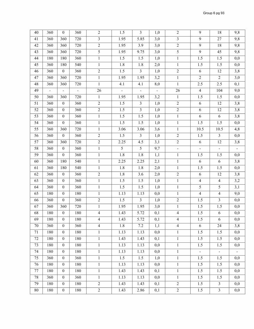
40 360 0 360 2 1.5 3 1,0 2 9 18 9,8 41 360 360 720 3 1.95 5.85 3,0 3 9 27 9,8 42 360 360 720 2 1.95 3.9 3,0 2 9 18 9,8 43 360 360 720 5 1.95 9.75 3,0 5 9 45 9,8 44 180 180 360 1 1.5 1.5 1,0 1 1.5 1.5 0,0 45 360 180 540 1 1.8 1.8 2,0 1 1.5 1.5 0,0 46 360 0 360 2 1.5 3 1,0 2 6 12 3,8 47 360 360 720 1 1.95 1.95 3,2 1 2 2 3,0 48 360 360 720 1 4.1 4.1 8,0 1 2.5 2.5 0,1 49 - - - 26 - - - 26 4 104 9,0 50 360 360 720 1 1.95 1.95 3,2 1 1.5 1.5 0,0 51 360 0 360 2 1.5 3 1,0 2 6 12 3,8 52 360 0 360 2 1.5 3 1,0 2 6 12 3,8 53 360 0 360 1 1.5 1.5 1,0 1 6 6 3,8 54 360 0 360 1 1.5 1.5 1,0 1 1.5 1.5 0,0 55 360 360 720 1 3.06 3.06 3,6 1 10.5 10.5 4,8 56 360 0 360 2 1.5 3 1,0 2 1.5 3 0,0 57 360 360 720 2 2.25 4.5 3,1 2 6 12 3,8 58 360 0 360 1 5 5 9,7 - - - - 59 360 0 360 1 1.8 1.8 1,1 1 1.5 1.5 0,0 60 360 180 540 1 2.25 2.25 2,1 1 6 6 3,8 61 360 180 540 1 1.8 1.8 2,0 1 1.5 1.5 0,0 62 360 0 360 2 1.8 3.6 2,0 2 6 12 3,8 63 360 0 360 1 1.5 1.5 1,0 1 4 4 3,2 64 360 0 360 1 1.5 1.5 1,0 1 5 5 3,1 65 180 0 180 1 1.13 1.13 0,0 1 4 4 9,0 66 360 0 360 2 1.5 3 1,0 2 1.5 3 0,0 67 360 360 720 1 1.95 1.95 3,0 1 1.5 1.5 0,0 68 180 0 180 4 1.43 5.72 0,1 4 1.5 6 0,0 69 180 0 180 4 1.43 5.72 0,1 4 1.5 6 0,0 70 360 0 360 4 1.8 7.2 1,1 4 6 24 3,8 71 180 0 180 1 1.13 1.13 0,0 1 1.5 1.5 0,0 72 180 0 180 1 1.43 1.43 0,1 1 1.5 1.5 0,0 73 180 0 180 1 1.13 1.13 0,0 1 1.5 1.5 0,0 74 180 0 180 1 1.13 1.13 0,0 1 - - - 75 360 0 360 1 1.5 1.5 1,0 1 1.5 1.5 0,0 76 180 0 180 1 1.13 1.13 0,0 1 1.5 1.5 0,0 77 180 0 180 1 1.43 1.43 0,1 1 1.5 1.5 0,0 78 360 0 360 1 1.13 1.13 0,0 1 1.5 1.5 0,0 79 180 0 180 2 1.43 1.43 0,1 2 1.5 3 0,0 80 180 0 180 2 1.43 2.86 0,1 2 1.5 3 0,0
Group 6 pg 93
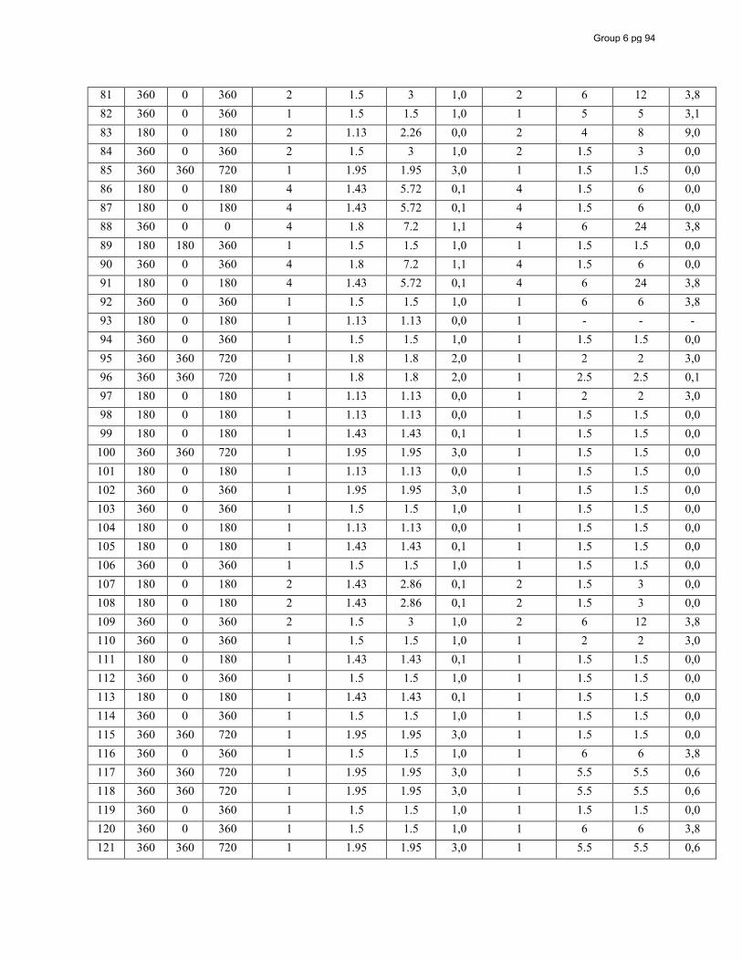
81 360 0 360 2 1.5 3 1,0 2 6 12 3,8 82 360 0 360 1 1.5 1.5 1,0 1 5 5 3,1 83 180 0 180 2 1.13 2.26 0,0 2 4 8 9,0 84 360 0 360 2 1.5 3 1,0 2 1.5 3 0,0 85 360 360 720 1 1.95 1.95 3,0 1 1.5 1.5 0,0 86 180 0 180 4 1.43 5.72 0,1 4 1.5 6 0,0 87 180 0 180 4 1.43 5.72 0,1 4 1.5 6 0,0 88 360 0 0 4 1.8 7.2 1,1 4 6 24 3,8 89 180 180 360 1 1.5 1.5 1,0 1 1.5 1.5 0,0 90 360 0 360 4 1.8 7.2 1,1 4 1.5 6 0,0 91 180 0 180 4 1.43 5.72 0,1 4 6 24 3,8 92 360 0 360 1 1.5 1.5 1,0 1 6 6 3,8 93 180 0 180 1 1.13 1.13 0,0 1 - - - 94 360 0 360 1 1.5 1.5 1,0 1 1.5 1.5 0,0 95 360 360 720 1 1.8 1.8 2,0 1 2 2 3,0 96 360 360 720 1 1.8 1.8 2,0 1 2.5 2.5 0,1 97 180 0 180 1 1.13 1.13 0,0 1 2 2 3,0 98 180 0 180 1 1.13 1.13 0,0 1 1.5 1.5 0,0 99 180 0 180 1 1.43 1.43 0,1 1 1.5 1.5 0,0
100 360 360 720 1 1.95 1.95 3,0 1 1.5 1.5 0,0 101 180 0 180 1 1.13 1.13 0,0 1 1.5 1.5 0,0 102 360 0 360 1 1.95 1.95 3,0 1 1.5 1.5 0,0 103 360 0 360 1 1.5 1.5 1,0 1 1.5 1.5 0,0 104 180 0 180 1 1.13 1.13 0,0 1 1.5 1.5 0,0 105 180 0 180 1 1.43 1.43 0,1 1 1.5 1.5 0,0 106 360 0 360 1 1.5 1.5 1,0 1 1.5 1.5 0,0 107 180 0 180 2 1.43 2.86 0,1 2 1.5 3 0,0 108 180 0 180 2 1.43 2.86 0,1 2 1.5 3 0,0 109 360 0 360 2 1.5 3 1,0 2 6 12 3,8 110 360 0 360 1 1.5 1.5 1,0 1 2 2 3,0 111 180 0 180 1 1.43 1.43 0,1 1 1.5 1.5 0,0 112 360 0 360 1 1.5 1.5 1,0 1 1.5 1.5 0,0 113 180 0 180 1 1.43 1.43 0,1 1 1.5 1.5 0,0 114 360 0 360 1 1.5 1.5 1,0 1 1.5 1.5 0,0 115 360 360 720 1 1.95 1.95 3,0 1 1.5 1.5 0,0 116 360 0 360 1 1.5 1.5 1,0 1 6 6 3,8 117 360 360 720 1 1.95 1.95 3,0 1 5.5 5.5 0,6 118 360 360 720 1 1.95 1.95 3,0 1 5.5 5.5 0,6 119 360 0 360 1 1.5 1.5 1,0 1 1.5 1.5 0,0 120 360 0 360 1 1.5 1.5 1,0 1 6 6 3,8 121 360 360 720 1 1.95 1.95 3,0 1 5.5 5.5 0,6
Group 6 pg 94
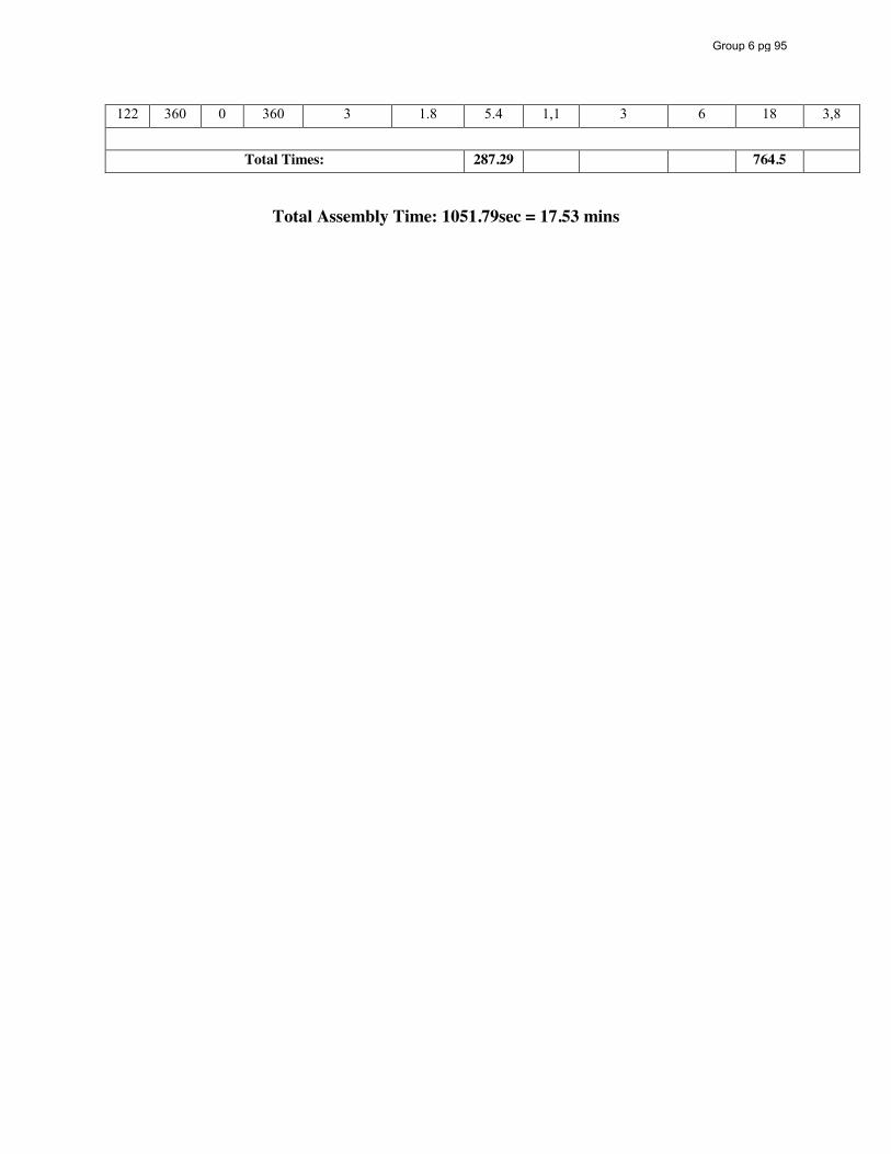
122 360 0 360 3 1.8 5.4 1,1 3 6 18 3,8
Total Times: 287.29 764.5
Total Assembly Time: 1051.79sec = 17.53 mins
Group 6 pg 95
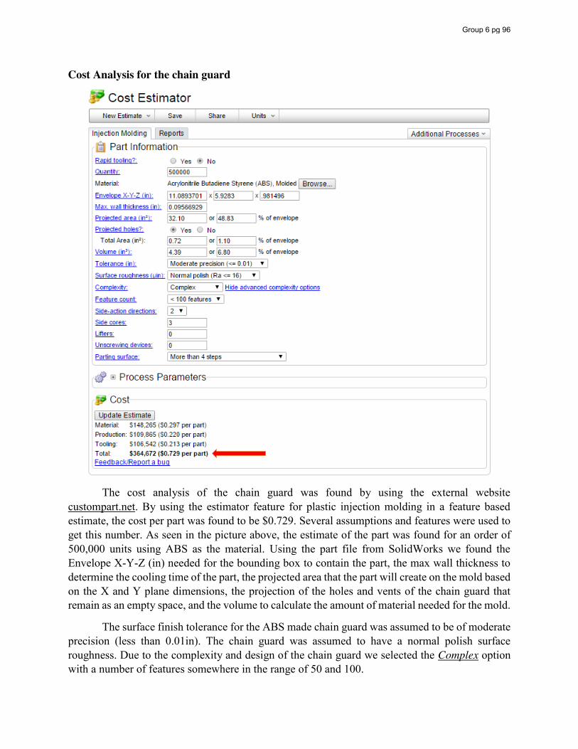
Cost Analysis for the chain guard
The cost analysis of the chain guard was found by using the external website custompart.net. By using the estimator feature for plastic injection molding in a feature based estimate, the cost per part was found to be $0.729. Several assumptions and features were used to get this number. As seen in the picture above, the estimate of the part was found for an order of 500,000 units using ABS as the material. Using the part file from SolidWorks we found the Envelope X-Y-Z (in) needed for the bounding box to contain the part, the max wall thickness to determine the cooling time of the part, the projected area that the part will create on the mold based on the X and Y plane dimensions, the projection of the holes and vents of the chain guard that remain as an empty space, and the volume to calculate the amount of material needed for the mold.
The surface finish tolerance for the ABS made chain guard was assumed to be of moderate precision (less than 0.01in). The chain guard was assumed to have a normal polish surface roughness. Due to the complexity and design of the chain guard we selected the Complex option with a number of features somewhere in the range of 50 and 100.
Group 6 pg 96
How It Works
Mechanical Processes The Scooter: The scooter is put into motion through a three step process. First, the throttle is twisted which sends an electrical signal through the throttle cable into the processor. The processor then uses power from the batteries to send a signal to the motor. Finally, the motor converts the electrical signal from the processor into mechanical power, through the rotation of its shaft and sprocket, which powers the drive train. To stop, the brake handle is compressed which pulls the brake cable. When the brake cable is pulled forward it in turn compresses the brake caliper creating friction against the brake drum slowing down the wheels. To support the weight of a rider, the scooter’s design disperses the load over the deck and frame so there is no concentrated load on a single element of the scooter’s frame. Drive Train:
Motion is transferred from the motor to the frame via the motion of multiple components. First motion is created inside the motor as electrical current from the battery is transformed into mechanical rotation of the drive shaft. A sprocket containing ten teeth is on the tip of the shaft spins at same speed. Around this sprocket, a roller chain is placed with the opposite end wrapped around the wheel sprocket. As the motor drive shaft rotates, the chain is spun as well, translating the motion to the wheel sprocket. A chain tensioner is placed beneath the chain to eliminate slack and ensure no slippage between the sprockets and chain will occur. The motor sprocket is attached with the outer rim of the clutch assembly, which in turn is connected to the inner rim but can only rotate in a single direction. As the sprocket turns, motion is transmitted to the rear wheel hub via the threaded inner rim of the clutch. The hub is what is directly connected to the rim and rear wheel of the scooter. A rear axle is fitted through the hub and wheel assembly and is bolted to the frame on both sides of the scooter. Therefore, as the wheel spins around the stationary axle and traction with the ground is initiated, the entire frame is propelled forward. If it is desired to decrease the speed of the frame, the brake function is initiated. The brake lever is pulled, which then contracts the brake pad around a brake drum attached to the hub, opposite of the chain. Friction is created slowing the rotation of the hub and wheel. Further analysis is presented in the succeeding sections. Chain Drive Assembly:
In order for the scooter to be driven, electrical power from the battery must be converted into mechanical power. This manipulation of energy takes place inside of the electric motor of the scooter. Magnets are installed inside the housing of the motor in order to create a magnetic field. Coils placed inside the motor carry an electric current from the battery source with a component called the commutator attached to the end of these coils. The purpose of the commutator is that it continuously reverses the electric current in the coils. Electric power is fed into the commutator through objects called brushes, which come in “brush” with the commutator. The alternating electric field created in the coils is then continually propelled to rotate in the presence of the static magnetic field from the batteries. Figure 1 shows a simple schematic of how this all works.
Group 6 pg 97
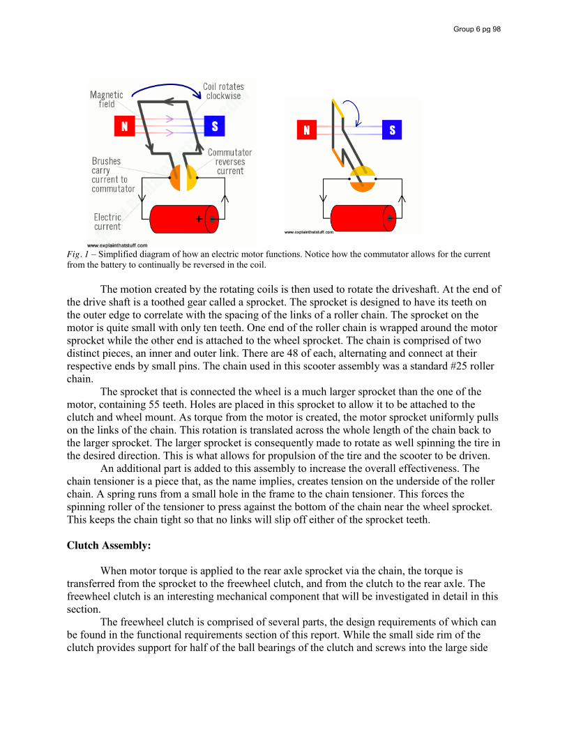
Fig. 1 – Simplified diagram of how an electric motor functions. Notice how the commutator allows for the current from the battery to continually be reversed in the coil.
The motion created by the rotating coils is then used to rotate the driveshaft. At the end of the drive shaft is a toothed gear called a sprocket. The sprocket is designed to have its teeth on the outer edge to correlate with the spacing of the links of a roller chain. The sprocket on the motor is quite small with only ten teeth. One end of the roller chain is wrapped around the motor sprocket while the other end is attached to the wheel sprocket. The chain is comprised of two distinct pieces, an inner and outer link. There are 48 of each, alternating and connect at their respective ends by small pins. The chain used in this scooter assembly was a standard #25 roller chain. The sprocket that is connected the wheel is a much larger sprocket than the one of the motor, containing 55 teeth. Holes are placed in this sprocket to allow it to be attached to the clutch and wheel mount. As torque from the motor is created, the motor sprocket uniformly pulls on the links of the chain. This rotation is translated across the whole length of the chain back to the larger sprocket. The larger sprocket is consequently made to rotate as well spinning the tire in the desired direction. This is what allows for propulsion of the tire and the scooter to be driven. An additional part is added to this assembly to increase the overall effectiveness. The chain tensioner is a piece that, as the name implies, creates tension on the underside of the roller chain. A spring runs from a small hole in the frame to the chain tensioner. This forces the spinning roller of the tensioner to press against the bottom of the chain near the wheel sprocket. This keeps the chain tight so that no links will slip off either of the sprocket teeth. Clutch Assembly: When motor torque is applied to the rear axle sprocket via the chain, the torque is transferred from the sprocket to the freewheel clutch, and from the clutch to the rear axle. The freewheel clutch is an interesting mechanical component that will be investigated in detail in this section. The freewheel clutch is comprised of several parts, the design requirements of which can be found in the functional requirements section of this report. While the small side rim of the clutch provides support for half of the ball bearings of the clutch and screws into the large side
Group 6 pg 98
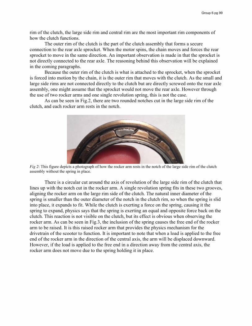
rim of the clutch, the large side rim and central rim are the most important rim components of how the clutch functions. The outer rim of the clutch is the part of the clutch assembly that forms a secure connection to the rear axle sprocket. When the motor spins, the chain moves and forces the rear sprocket to move in the same direction. An important observation is made in that the sprocket is not directly connected to the rear axle. The reasoning behind this observation will be explained in the coming paragraphs. Because the outer rim of the clutch is what is attached to the sprocket, when the sprocket is forced into motion by the chain, it is the outer rim that moves with the clutch. As the small and large side rims are not connected directly to the clutch but are directly screwed onto the rear axle assembly, one might assume that the sprocket would not move the rear axle. However through the use of two rocker arms and one single revolution spring, this is not the case. As can be seen in Fig.2, there are two rounded notches cut in the large side rim of the clutch, and each rocker arm rests in the notch.
Fig 2: This figure depicts a photograph of how the rocker arm rests in the notch of the large side rim of the clutch assembly without the spring in place. There is a circular cut around the axis of revolution of the large side rim of the clutch that lines up with the notch cut in the rocker arm. A single revolution spring fits in these two grooves, aligning the rocker arm on the large rim side of the clutch. The natural inner diameter of the spring is smaller than the outer diameter of the notch in the clutch rim, so when the spring is slid into place, it expands to fit. While the clutch is exerting a force on the spring, causing it the spring to expand, physics says that the spring is exerting an equal and opposite force back on the clutch. This reaction is not visible on the clutch, but its effect is obvious when observing the rocker arm. As can be seen in Fig.3, the inclusion of the spring causes the free end of the rocker arm to be raised. It is this raised rocker arm that provides the physics mechanism for the drivetrain of the scooter to function. It is important to note that when a load is applied to the free end of the rocker arm in the direction of the central axis, the arm will be displaced downward. However, if the load is applied to the free end in a direction away from the central axis, the rocker arm does not move due to the spring holding it in place.
Group 6 pg 99
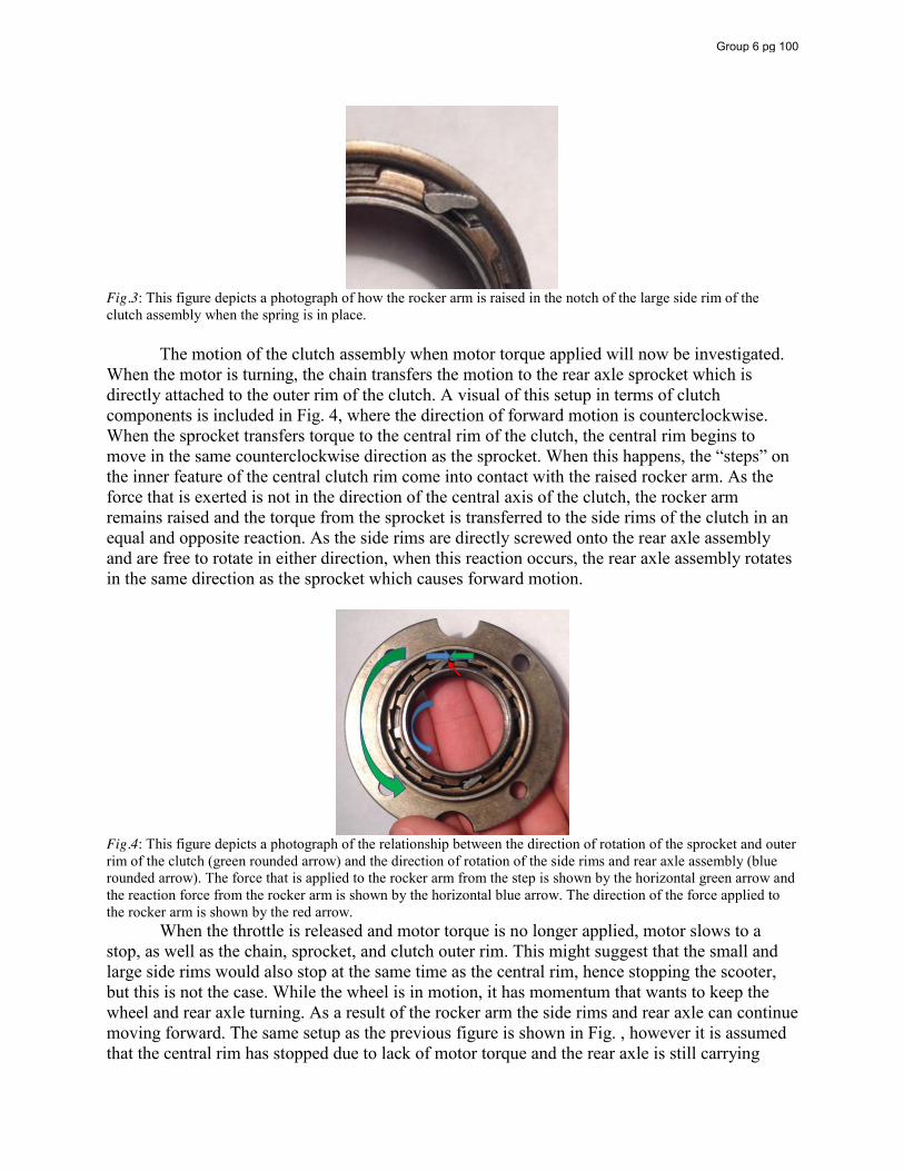
Fig.3: This figure depicts a photograph of how the rocker arm is raised in the notch of the large side rim of the clutch assembly when the spring is in place. The motion of the clutch assembly when motor torque applied will now be investigated. When the motor is turning, the chain transfers the motion to the rear axle sprocket which is directly attached to the outer rim of the clutch. A visual of this setup in terms of clutch components is included in Fig. 4, where the direction of forward motion is counterclockwise. When the sprocket transfers torque to the central rim of the clutch, the central rim begins to move in the same counterclockwise direction as the sprocket. When this happens, the “steps” on the inner feature of the central clutch rim come into contact with the raised rocker arm. As the force that is exerted is not in the direction of the central axis of the clutch, the rocker arm remains raised and the torque from the sprocket is transferred to the side rims of the clutch in an equal and opposite reaction. As the side rims are directly screwed onto the rear axle assembly and are free to rotate in either direction, when this reaction occurs, the rear axle assembly rotates in the same direction as the sprocket which causes forward motion.
Fig.4: This figure depicts a photograph of the relationship between the direction of rotation of the sprocket and outer rim of the clutch (green rounded arrow) and the direction of rotation of the side rims and rear axle assembly (blue rounded arrow). The force that is applied to the rocker arm from the step is shown by the horizontal green arrow and the reaction force from the rocker arm is shown by the horizontal blue arrow. The direction of the force applied to the rocker arm is shown by the red arrow. When the throttle is released and motor torque is no longer applied, motor slows to a stop, as well as the chain, sprocket, and clutch outer rim. This might suggest that the small and large side rims would also stop at the same time as the central rim, hence stopping the scooter, but this is not the case. While the wheel is in motion, it has momentum that wants to keep the wheel and rear axle turning. As a result of the rocker arm the side rims and rear axle can continue moving forward. The same setup as the previous figure is shown in Fig. , however it is assumed that the central rim has stopped due to lack of motor torque and the rear axle is still carrying
Group 6 pg 100
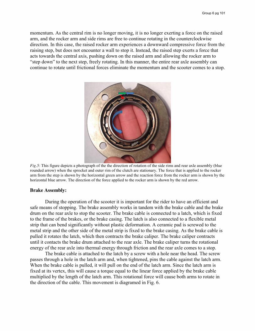
momentum. As the central rim is no longer moving, it is no longer exerting a force on the raised arm, and the rocker arm and side rims are free to continue rotating in the counterclockwise direction. In this case, the raised rocker arm experiences a downward compressive force from the raising step, but does not encounter a wall to stop it. Instead, the raised step exerts a force that acts towards the central axis, pushing down on the raised arm and allowing the rocker arm to “step down” to the next step, freely rotating. In this manner, the entire rear axle assembly can continue to rotate until frictional forces eliminate the momentum and the scooter comes to a stop.
Fig.5: This figure depicts a photograph of the the direction of rotation of the side rims and rear axle assembly (blue rounded arrow) when the sprocket and outer rim of the clutch are stationary. The force that is applied to the rocker arm from the step is shown by the horizontal green arrow and the reaction force from the rocker arm is shown by the horizontal blue arrow. The direction of the force applied to the rocker arm is shown by the red arrow. Brake Assembly: During the operation of the scooter it is important for the rider to have an efficient and safe means of stopping. The brake assembly works in tandem with the brake cable and the brake drum on the rear axle to stop the scooter. The brake cable is connected to a latch, which is fixed to the frame of the brakes, or the brake casing. The latch is also connected to a flexible metal strip that can bend significantly without plastic deformation. A ceramic pad is screwed to the metal strip and the other side of the metal strip is fixed to the brake casing. As the brake cable is pulled it rotates the latch, which then contracts the brake caliper. The brake caliper contracts until it contacts the brake drum attached to the rear axle. The brake caliper turns the rotational energy of the rear axle into thermal energy through friction and the rear axle comes to a stop. The brake cable is attached to the latch by a screw with a hole near the head. The screw passes through a hole in the latch arm and, when tightened, pins the cable against the latch arm. When the brake cable is pulled, it will pull on the end of the latch arm. Since the latch arm is fixed at its vertex, this will cause a torque equal to the linear force applied by the brake cable multiplied by the length of the latch arm. This rotational force will cause both arms to rotate in the direction of the cable. This movement is diagramed in Fig. 6.
Group 6 pg 101
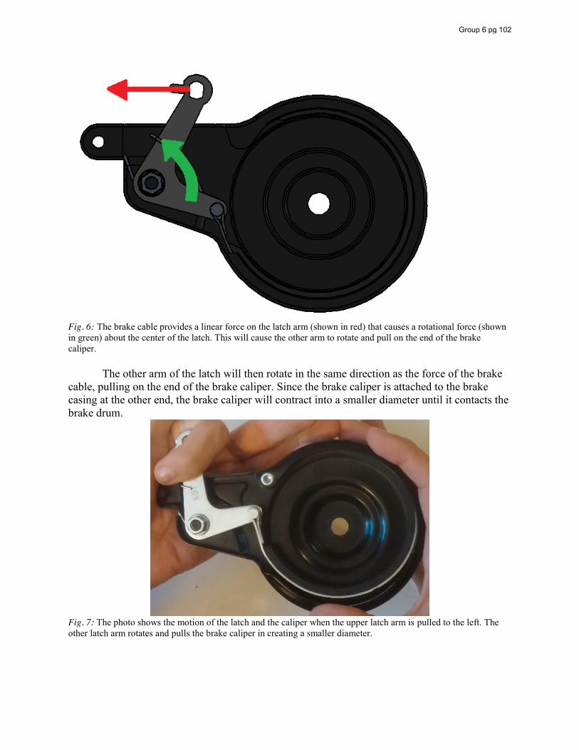
Fig. 6: The brake cable provides a linear force on the latch arm (shown in red) that causes a rotational force (shown in green) about the center of the latch. This will cause the other arm to rotate and pull on the end of the brake caliper.
The other arm of the latch will then rotate in the same direction as the force of the brake cable, pulling on the end of the brake caliper. Since the brake caliper is attached to the brake casing at the other end, the brake caliper will contract into a smaller diameter until it contacts the brake drum.
Fig. 7: The photo shows the motion of the latch and the caliper when the upper latch arm is pulled to the left. The other latch arm rotates and pulls the brake caliper in creating a smaller diameter.
Group 6 pg 102
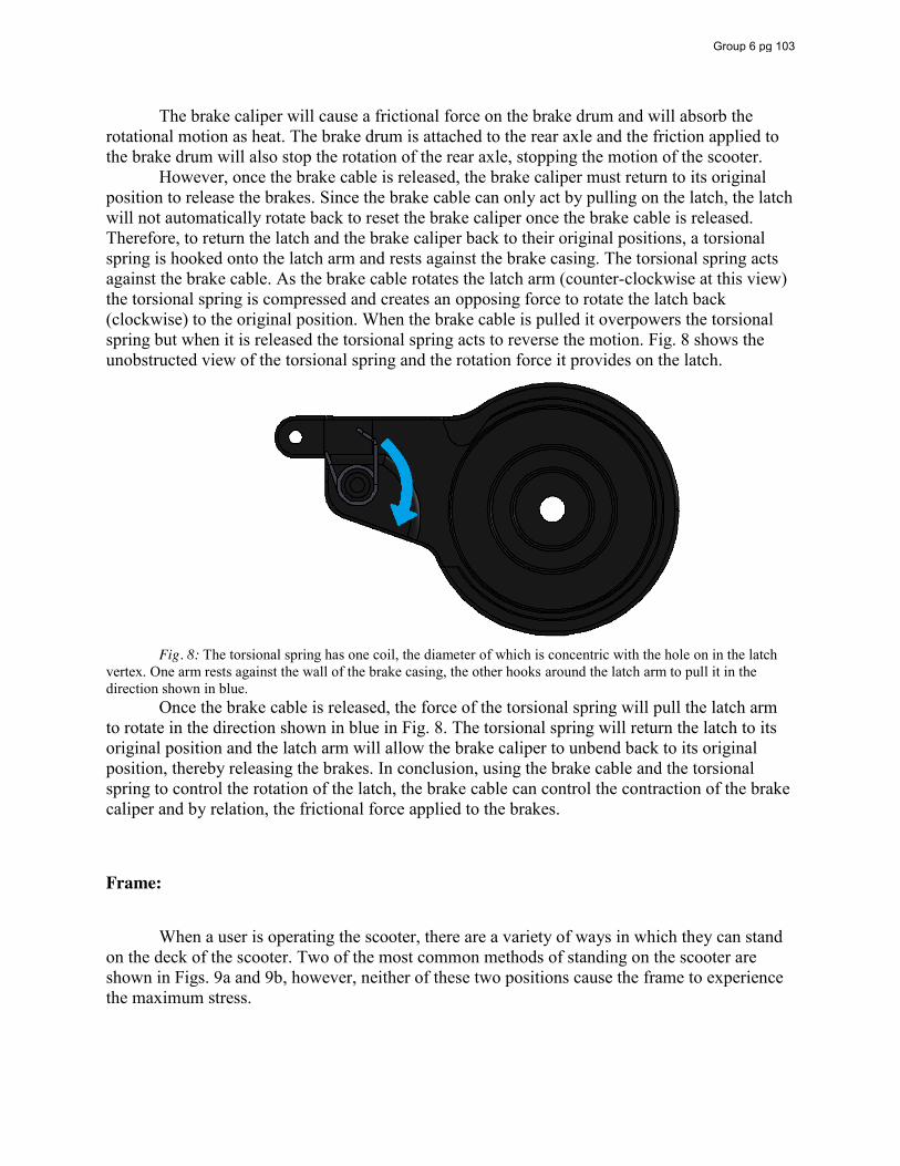
The brake caliper will cause a frictional force on the brake drum and will absorb the rotational motion as heat. The brake drum is attached to the rear axle and the friction applied to the brake drum will also stop the rotation of the rear axle, stopping the motion of the scooter.
However, once the brake cable is released, the brake caliper must return to its original position to release the brakes. Since the brake cable can only act by pulling on the latch, the latch will not automatically rotate back to reset the brake caliper once the brake cable is released. Therefore, to return the latch and the brake caliper back to their original positions, a torsional spring is hooked onto the latch arm and rests against the brake casing. The torsional spring acts against the brake cable. As the brake cable rotates the latch arm (counter-clockwise at this view) the torsional spring is compressed and creates an opposing force to rotate the latch back (clockwise) to the original position. When the brake cable is pulled it overpowers the torsional spring but when it is released the torsional spring acts to reverse the motion. Fig. 8 shows the unobstructed view of the torsional spring and the rotation force it provides on the latch.
Fig. 8: The torsional spring has one coil, the diameter of which is concentric with the hole on in the latch
vertex. One arm rests against the wall of the brake casing, the other hooks around the latch arm to pull it in the direction shown in blue. Once the brake cable is released, the force of the torsional spring will pull the latch arm to rotate in the direction shown in blue in Fig. 8. The torsional spring will return the latch to its original position and the latch arm will allow the brake caliper to unbend back to its original position, thereby releasing the brakes. In conclusion, using the brake cable and the torsional spring to control the rotation of the latch, the brake cable can control the contraction of the brake caliper and by relation, the frictional force applied to the brakes.
Frame:
When a user is operating the scooter, there are a variety of ways in which they can stand on the deck of the scooter. Two of the most common methods of standing on the scooter are shown in Figs. 9a and 9b, however, neither of these two positions cause the frame to experience the maximum stress.
Group 6 pg 103
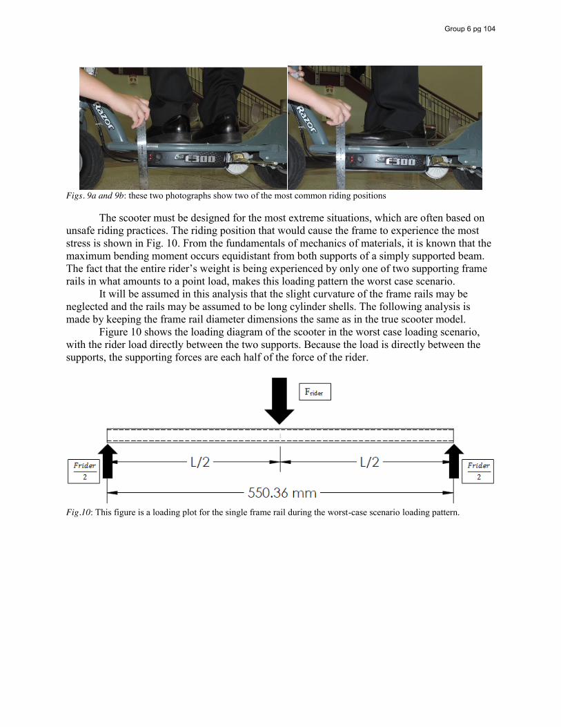
Figs. 9a and 9b: these two photographs show two of the most common riding positions The scooter must be designed for the most extreme situations, which are often based on unsafe riding practices. The riding position that would cause the frame to experience the most stress is shown in Fig. 10. From the fundamentals of mechanics of materials, it is known that the maximum bending moment occurs equidistant from both supports of a simply supported beam. The fact that the entire rider’s weight is being experienced by only one of two supporting frame rails in what amounts to a point load, makes this loading pattern the worst case scenario. It will be assumed in this analysis that the slight curvature of the frame rails may be neglected and the rails may be assumed to be long cylinder shells. The following analysis is made by keeping the frame rail diameter dimensions the same as in the true scooter model. Figure 10 shows the loading diagram of the scooter in the worst case loading scenario, with the rider load directly between the two supports. Because the load is directly between the supports, the supporting forces are each half of the force of the rider.
Fig.10: This figure is a loading plot for the single frame rail during the worst-case scenario loading pattern.
Group 6 pg 104
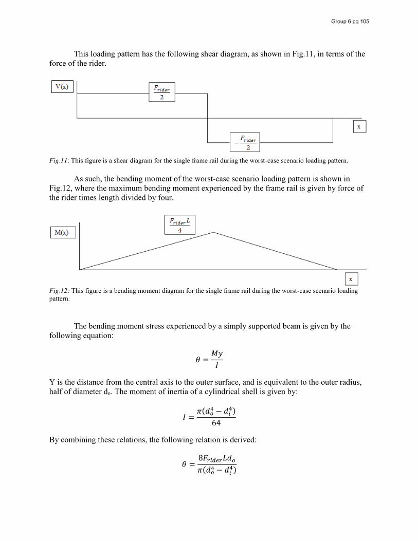
This loading pattern has the following shear diagram, as shown in Fig.11, in terms of the force of the rider.
Fig.11: This figure is a shear diagram for the single frame rail during the worst-case scenario loading pattern. As such, the bending moment of the worst-case scenario loading pattern is shown in Fig.12, where the maximum bending moment experienced by the frame rail is given by force of the rider times length divided by four.
Fig.12: This figure is a bending moment diagram for the single frame rail during the worst-case scenario loading pattern. The bending moment stress experienced by a simply supported beam is given by the following equation:
𝜃 =𝑀𝑦𝐼
Y is the distance from the central axis to the outer surface, and is equivalent to the outer radius, half of diameter do. The moment of inertia of a cylindrical shell is given by:
𝐼 =𝜋(𝑑 − 𝑑 )
64
By combining these relations, the following relation is derived:
𝜃 =8𝐹 𝐿𝑑𝜋(𝑑 − 𝑑 )
Group 6 pg 105
When known values are plugged in, the stress is given as a function of the force of the rider:
𝜃 = 0.206𝐹 (𝑀𝑃𝑎)
The yield strength of steel is 250MPa. By using this value as the stress experienced by the single frame rail and solving for Frider, it is found that the maximum force that can be exerted by the rider is 1210 Newtons. Dividing this force by gravity results in a rider mass of 124 kg. This means that riders under 124 kg can stand on the scooter in the worst case position and not yield the frame.
The recommended rider mass is 100 kg, as found in the owner’s manual. Thus, the recommended mass in comparison to the worst case scenario rider position and rider mass before yield results in a factor of safety of 1.24. This factor of safety seems low, but the assumptions made in this calculation must be taken into consideration. It is assumed that the load is applied at a single point. However, it is impossible to exactly replicate a point load as the rider’s mass will be distributed somewhat throughout their foot and onto the scooter. This distribution lessens the intensity of the reaction. Additionally, most riders will either not be able to or choose not to ride in the worst case position, either for lack of dexterity, or desire to be safe. In a safe riding position, the rider’s weight will be distributed across both of the frame rails. Assuming that each frame rail can withstand 124 kg before yield (for a total of 248 kg of rider mass), the recommended rider mass results in a factor of safety of 2.48. This factor of safety is much more appropriate. Realizing that the frame cross members also experience rider mass, it is likely that the true factor of safety is greater than 3.5. As a result, it can be assumed that the frame is more than capable of supporting the listed maximum rider mass. Front Fork Assembly:
The front fork bar assembly is used to connect the steering components to the body of the scooter. The front fork bar assembly is made of a central pipe that has two arms that branch off near the bottom of the central pipe. The two arms each have a tab on the end with a hole in it. The two tabs are connected to each side of the front axle. The central pipe of the front fork bar passes through a cylindrical collar on the scooter body to connect the steering to the rest of the scooter. The handlebars are then inserted over top of the central pipe and the handlebar shaft is clamped onto the front fork central pipe so that the front fork bar will rotate with the handlebars. The front fork assembly has two bearing washers to reduce friction between the front fork bar and the collar while the front fork bar is turned. It also has two fasteners, referred to as the headset (headset nuts individually), that prevent the collar from sliding along the front fork bar. The front fork bar and its components are shown in Fig. 13 below.
Group 6 pg 106
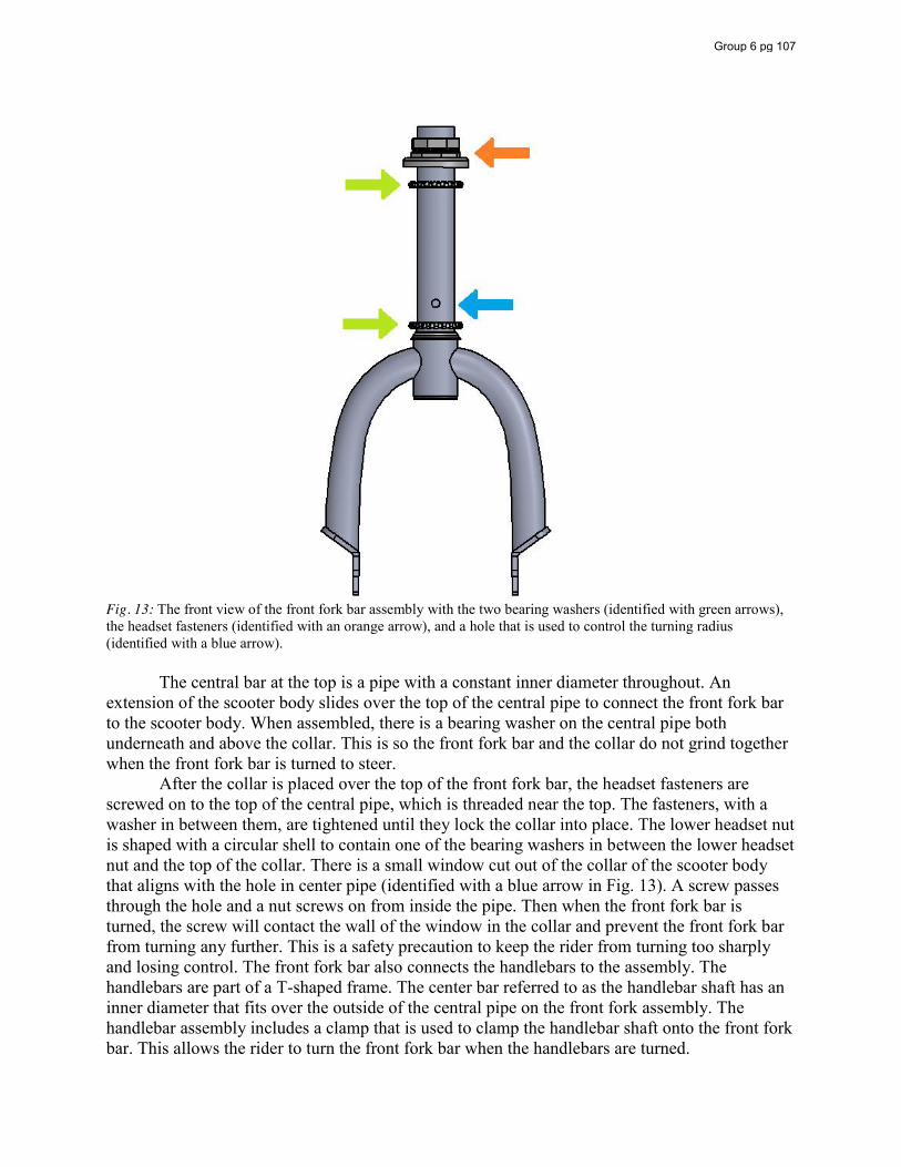
Fig. 13: The front view of the front fork bar assembly with the two bearing washers (identified with green arrows), the headset fasteners (identified with an orange arrow), and a hole that is used to control the turning radius (identified with a blue arrow). The central bar at the top is a pipe with a constant inner diameter throughout. An extension of the scooter body slides over the top of the central pipe to connect the front fork bar to the scooter body. When assembled, there is a bearing washer on the central pipe both underneath and above the collar. This is so the front fork bar and the collar do not grind together when the front fork bar is turned to steer. After the collar is placed over the top of the front fork bar, the headset fasteners are screwed on to the top of the central pipe, which is threaded near the top. The fasteners, with a washer in between them, are tightened until they lock the collar into place. The lower headset nut is shaped with a circular shell to contain one of the bearing washers in between the lower headset nut and the top of the collar. There is a small window cut out of the collar of the scooter body that aligns with the hole in center pipe (identified with a blue arrow in Fig. 13). A screw passes through the hole and a nut screws on from inside the pipe. Then when the front fork bar is turned, the screw will contact the wall of the window in the collar and prevent the front fork bar from turning any further. This is a safety precaution to keep the rider from turning too sharply and losing control. The front fork bar also connects the handlebars to the assembly. The handlebars are part of a T-shaped frame. The center bar referred to as the handlebar shaft has an inner diameter that fits over the outside of the central pipe on the front fork assembly. The handlebar assembly includes a clamp that is used to clamp the handlebar shaft onto the front fork bar. This allows the rider to turn the front fork bar when the handlebars are turned.
Group 6 pg 107
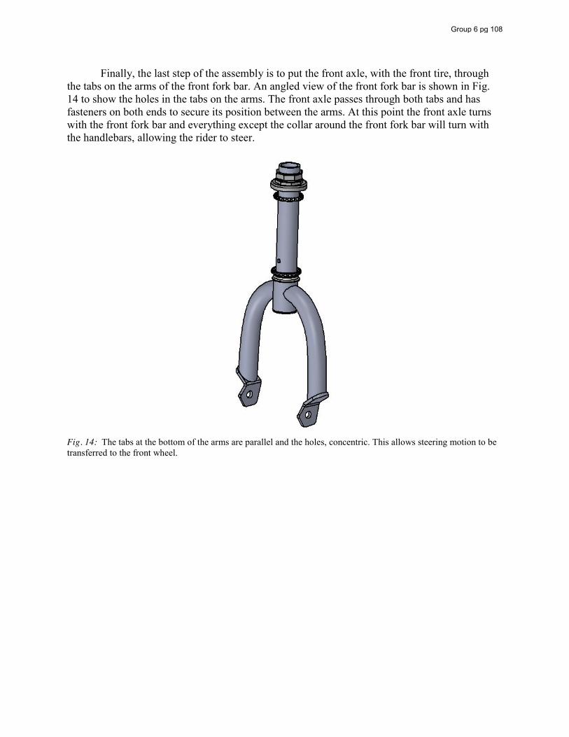
Finally, the last step of the assembly is to put the front axle, with the front tire, through the tabs on the arms of the front fork bar. An angled view of the front fork bar is shown in Fig. 14 to show the holes in the tabs on the arms. The front axle passes through both tabs and has fasteners on both ends to secure its position between the arms. At this point the front axle turns with the front fork bar and everything except the collar around the front fork bar will turn with the handlebars, allowing the rider to steer.
Fig. 14: The tabs at the bottom of the arms are parallel and the holes, concentric. This allows steering motion to be transferred to the front wheel.
Group 6 pg 108
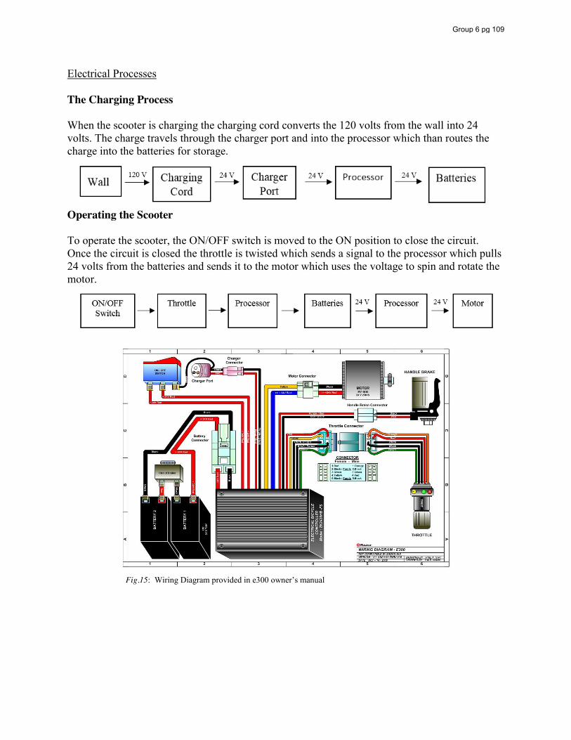
Electrical Processes The Charging Process When the scooter is charging the charging cord converts the 120 volts from the wall into 24 volts. The charge travels through the charger port and into the processor which than routes the charge into the batteries for storage.
Operating the Scooter To operate the scooter, the ON/OFF switch is moved to the ON position to close the circuit. Once the circuit is closed the throttle is twisted which sends a signal to the processor which pulls 24 volts from the batteries and sends it to the motor which uses the voltage to spin and rotate the motor.
Fig.15: Wiring Diagram provided in e300 owner’s manual
Group 6 pg 109

Heat Transfer Due to the fact that electricity is flowing through the motor and components are moving at high speeds, heat is naturally created inside the motor. This heat builds up and is then distributed throughout the entire motor. In order to help dissipate the heat, fins are designed onto the side of the motor. With the addition of these fins the surface area is significantly increased, helping the rate of convection heat transfer from the motor to the surrounding air to increase as well. Newton’s law of cooling gives us the formula:
𝑞 = ℎ 𝐴 ∆𝑇 where q is the amount of heat transferred per unit time, A is the heat transfer surface area, hc is the convective heat transfer coefficient, and ∆𝑇 is the temperature difference between the surface and the surrounding fluid (in this case air). This relationship clearly shows the benefit of increasing surface area with the use of fins. Temperatures were taken at different locations on the motor during multiple performance runs and the data displayed in Table 16: Motor Location Room
Temperature No load with
open throttle for 90 seconds after starting at room
temperature
175 lb rider, up hill, starting at
room temperature
175 lb rider, free ride for 3
minutes up and down hills and on flat ground
Sprocket Side 26.1 C 30 C 32.8 C 39.4 C Fin Side 26.2 C 30 C 31.2 C 44.4 C
Cast Iron Side 26.0 C 26.6 C 29.9 C 36.6 C For a load of 175 pounds riding for three minutes and using a convection heat transfer coefficient for the surrounding air to be about 100 W/(m2 K), the amount of heat transfer for the fin side was found:
𝑞 = ℎ 𝐴 ∆𝑇 = 100𝑊𝑚 𝐾
(8794.48 𝑚𝑚 )(44.4℃ − 26.2℃)1 𝑚
1000 𝑚𝑚 = 16.0 𝑊
For the sprocket side:
𝑞 = ℎ 𝐴 ∆𝑇 = 100𝑊𝑚 𝐾
(7030.72 𝑚𝑚 )(39.4℃ − 26.1℃)1 𝑚
1000 𝑚𝑚 = 9.35 𝑊
And for the cast iron side: 𝑞 = ℎ 𝐴 ∆𝑇
= 100𝑊𝑚 𝐾
(17 152.65 𝑚𝑚 )(36.6℃ − 26.0℃)1 𝑚
1000 𝑚𝑚 = 18.18 𝑊
Group 6 pg 110
Although that for a more in-depth analysis of heat transfer additional temperatures at multiple locations would need to be taken, much can still be learned from the values calculated. The simple addition of sixteen fins increased surface area by about 25% but nearly double the amount of heat transfer compared with the sprocket side. This is attributed to the overall effectiveness of the fins. It can also be seen from the table that the fins do not become very much effective until the scooter has been running for quite some time and the temperature has been raised notably.
The cast iron part of the motor takes up the majority of the surface area for the motor, but can be seen to transfer heat significantly less per unit area. It can be hypothesized that this happens due to the fact that the cast iron has lower thermal conductivity compared with the other sides. Along with the heat loss from natural convection that was calculated, some heat is disbursed through radiation and also loss in the contact surface between the motor components. The capabilities for finding these unknown heat losses require much more precise and elaborate equipment that is beyond the scope of this course, but estimates can be made. If one looks and takes into account that the motor runs at 250 W with an efficiency of about 78%, it can be seen that heat loss accounts for about 55 W. The sum of all the convection heat losses calculated reaches about 43.5 W. The additional 11.5 W can be attributed to certain surface areas not included in the calculations, as well as some loss due to radiation. This is a reasonable assumption that correlates well with all the data collected.
Group 6 pg 111
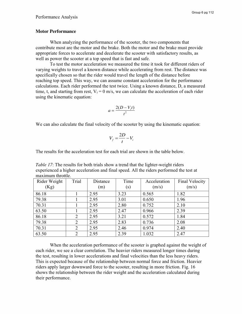
Performance Analysis
Motor Performance
When analyzing the performance of the scooter, the two components that contribute most are the motor and the brake. Both the motor and the brake must provide appropriate forces to accelerate and decelerate the scooter with satisfactory results, as well as power the scooter at a top speed that is fast and safe.
To test the motor acceleration we measured the time it took for different riders of varying weights to travel a known distance while accelerating from rest. The distance was specifically chosen so that the rider would travel the length of the distance before reaching top speed. This way, we can assume constant acceleration for the performance calculations. Each rider performed the test twice. Using a known distance, D, a measured time, t, and starting from rest, Vi = 0 m/s, we can calculate the acceleration of each rider using the kinematic equation:
��
a 2(D �Vit)t 2
We can also calculate the final velocity of the scooter by using the kinematic equation:
��
Vf 2Dt�Vi
The results for the acceleration test for each trial are shown in the table below. Table 17: The results for both trials show a trend that the lighter-weight riders experienced a higher acceleration and final speed. All the riders performed the test at maximum throttle. Rider Weight
(Kg) Trial Distance
(m) Time
(s) Acceleration
(m/s) Final Velocity
(m/s) 86.18 1 2.95 3.23 0.565 1.82 79.38 1 2.95 3.01 0.650 1.96 70.31 1 2.95 2.80 0.752 2.10 63.50 1 2.95 2.47 0.966 2.39 86.18 2 2.95 3.21 0.572 1.84 79.38 2 2.95 2.83 0.736 2.08 70.31 2 2.95 2.46 0.974 2.40 63.50 2 2.95 2.39 1.032 2.47 When the acceleration performance of the scooter is graphed against the weight of each rider, we see a clear correlation. The heavier riders measured longer times during the test, resulting in lower accelerations and final velocities than the less heavy riders. This is expected because of the relationship between normal force and friction. Heavier riders apply larger downward force to the scooter, resulting in more friction. Fig. 16 shows the relationship between the rider weight and the acceleration calculated during their performance.
Group 6 pg 112
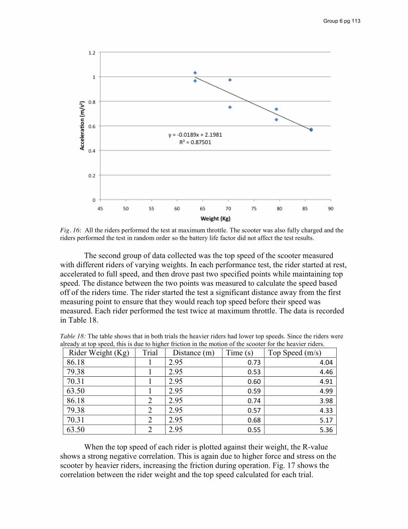
Fig. 16: All the riders performed the test at maximum throttle. The scooter was also fully charged and the riders performed the test in random order so the battery life factor did not affect the test results. The second group of data collected was the top speed of the scooter measured with different riders of varying weights. In each performance test, the rider started at rest, accelerated to full speed, and then drove past two specified points while maintaining top speed. The distance between the two points was measured to calculate the speed based off of the riders time. The rider started the test a significant distance away from the first measuring point to ensure that they would reach top speed before their speed was measured. Each rider performed the test twice at maximum throttle. The data is recorded in Table 18. Table 18: The table shows that in both trials the heavier riders had lower top speeds. Since the riders were already at top speed, this is due to higher friction in the motion of the scooter for the heavier riders.
Rider Weight (Kg) Trial Distance (m) Time (s) Top Speed (m/s) 86.18 1 2.95 0.73 4.04 79.38 1 2.95 0.53 4.46 70.31 1 2.95 0.60 4.91 63.50 1 2.95 0.59 4.99 86.18 2 2.95 0.74 3.98 79.38 2 2.95 0.57 4.33 70.31 2 2.95 0.68 5.17 63.50 2 2.95 0.55 5.36
When the top speed of each rider is plotted against their weight, the R-value shows a strong negative correlation. This is again due to higher force and stress on the scooter by heavier riders, increasing the friction during operation. Fig. 17 shows the correlation between the rider weight and the top speed calculated for each trial.
Group 6 pg 113
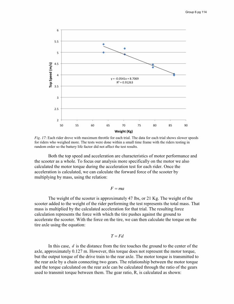
Fig. 17: Each rider drove with maximum throttle for each trial. The data for each trial shows slower speeds for riders who weighed more. The tests were done within a small time frame with the riders testing in random order so the battery life factor did not affect the test results. Both the top speed and acceleration are characteristics of motor performance and the scooter as a whole. To focus our analysis more specifically on the motor we also calculated the motor torque during the acceleration test for each rider. Once the acceleration is calculated, we can calculate the forward force of the scooter by multiplying by mass, using the relation:
��
F ma
The weight of the scooter is approximately 47 lbs, or 21 Kg. The weight of the scooter added to the weight of the rider performing the test represents the total mass. That mass is multiplied by the calculated acceleration for that trial. The resulting force calculation represents the force with which the tire pushes against the ground to accelerate the scooter. With the force on the tire, we can then calculate the torque on the tire axle using the equation:
��
T Fd In this case,
��
d is the distance from the tire touches the ground to the center of the axle, approximately 0.127 m. However, this torque does not represent the motor torque, but the output torque of the drive train to the rear axle. The motor torque is transmitted to the rear axle by a chain connecting two gears. The relationship between the motor torque and the torque calculated on the rear axle can be calculated through the ratio of the gears used to transmit torque between them. The gear ratio, R, is calculated as shown:
Group 6 pg 114
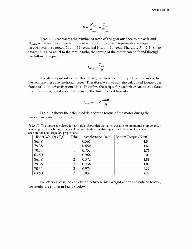
��
R Naxle
Nmotor
TaxleTmotor
Here, Naxle represents the number of teeth of the gear attached to the axle and Nmotor is the number of teeth on the gear for motor, while T represents the respective torques. For the scooter, Naxle = 55 teeth, and Nmotor = 10 teeth. Therefore R = 5.5. Since this ratio is also equal to the torque ratio, the torque of the motor can be found through the following equation:
��
Tmotor TaxleR
It is also important to note that during transmission of torque from the motor to the rear tire there are frictional losses. Therefore, we multiply the calculated torque by a factor of 1.1 to cover frictional loss. Therefore the torque for each rider can be calculated from their weight and acceleration using the final derived formula:
��
Tmotor 1.1umadR
Table 19 shows the calculated data for the torque of the motor during the performance test of each rider. Table 19: The torque calculated for each rider shows that the motor was able to output more torque under less weight. This is because the acceleration calculated is also higher for light weight riders and acceleration and torque are proportional.
Rider Weight (Kg) Trial Acceleration (m/s) Motor Torque (N*m) 86.18 1 0.565 1.54 79.38 1 0.650 1.66 70.31 1 0.752 1.75 63.50 1 0.966 2.08 86.18 2 0.572 1.56 79.38 2 0.736 1.88 70.31 2 0.974 2.27 63.50 2 1.032 2.22
To better express the correlation between rider weight and the calculated torque, the results are shown in Fig. 18 below.
Group 6 pg 115
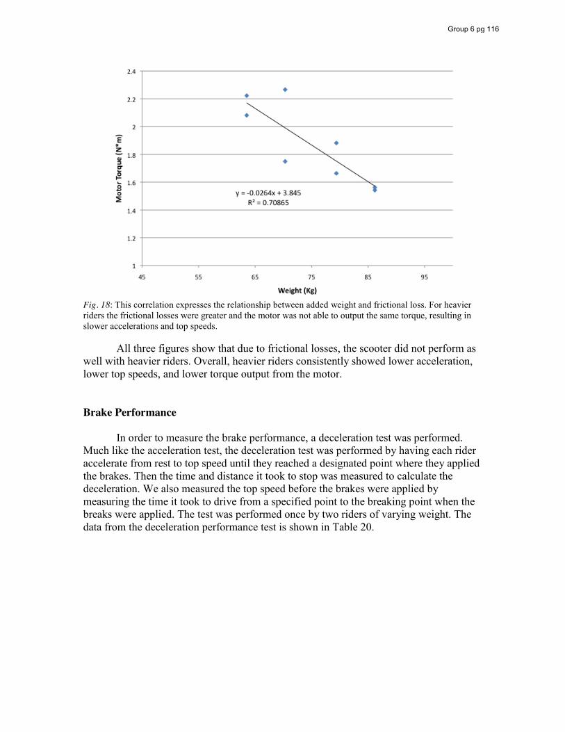
Fig. 18: This correlation expresses the relationship between added weight and frictional loss. For heavier riders the frictional losses were greater and the motor was not able to output the same torque, resulting in slower accelerations and top speeds. All three figures show that due to frictional losses, the scooter did not perform as well with heavier riders. Overall, heavier riders consistently showed lower acceleration, lower top speeds, and lower torque output from the motor. Brake Performance In order to measure the brake performance, a deceleration test was performed. Much like the acceleration test, the deceleration test was performed by having each rider accelerate from rest to top speed until they reached a designated point where they applied the brakes. Then the time and distance it took to stop was measured to calculate the deceleration. We also measured the top speed before the brakes were applied by measuring the time it took to drive from a specified point to the breaking point when the breaks were applied. The test was performed once by two riders of varying weight. The data from the deceleration performance test is shown in Table 20.
Group 6 pg 116
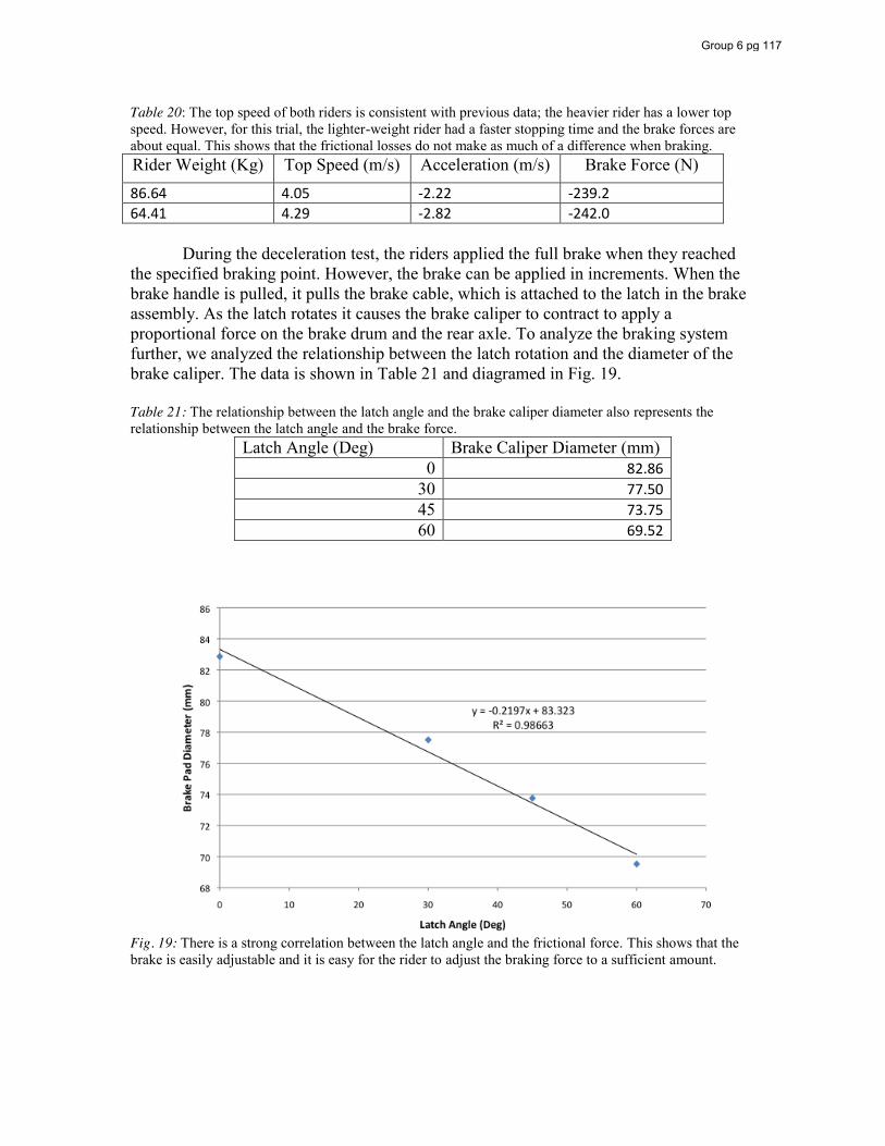
Table 20: The top speed of both riders is consistent with previous data; the heavier rider has a lower top speed. However, for this trial, the lighter-weight rider had a faster stopping time and the brake forces are about equal. This shows that the frictional losses do not make as much of a difference when braking. Rider Weight (Kg) Top Speed (m/s) Acceleration (m/s) Brake Force (N)
86.64 4.05 -2.22 -239.2 64.41 4.29 -2.82 -242.0 During the deceleration test, the riders applied the full brake when they reached the specified braking point. However, the brake can be applied in increments. When the brake handle is pulled, it pulls the brake cable, which is attached to the latch in the brake assembly. As the latch rotates it causes the brake caliper to contract to apply a proportional force on the brake drum and the rear axle. To analyze the braking system further, we analyzed the relationship between the latch rotation and the diameter of the brake caliper. The data is shown in Table 21 and diagramed in Fig. 19. Table 21: The relationship between the latch angle and the brake caliper diameter also represents the relationship between the latch angle and the brake force.
Latch Angle (Deg) Brake Caliper Diameter (mm) 0 82.86
30 77.50 45 73.75 60 69.52
Fig. 19: There is a strong correlation between the latch angle and the frictional force. This shows that the brake is easily adjustable and it is easy for the rider to adjust the braking force to a sufficient amount.
Group 6 pg 117

Appendix A:
Closure Equations
Group 6 pg 118
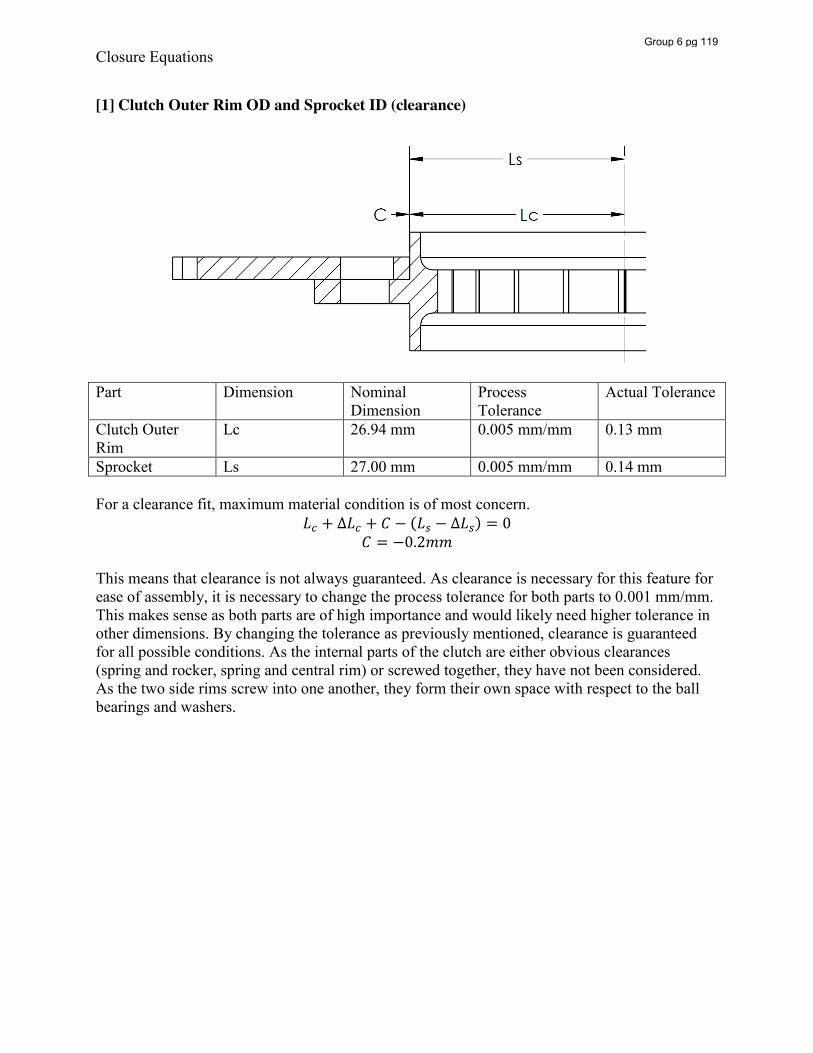
Closure Equations
[1] Clutch Outer Rim OD and Sprocket ID (clearance)
Part Dimension Nominal Dimension
Process Tolerance
Actual Tolerance
Clutch Outer Rim
Lc 26.94 mm 0.005 mm/mm 0.13 mm
Sprocket Ls 27.00 mm 0.005 mm/mm 0.14 mm For a clearance fit, maximum material condition is of most concern.
𝐿 + ∆𝐿 + 𝐶 − (𝐿 − ∆𝐿 ) = 0 𝐶 = −0.2𝑚𝑚
This means that clearance is not always guaranteed. As clearance is necessary for this feature for ease of assembly, it is necessary to change the process tolerance for both parts to 0.001 mm/mm. This makes sense as both parts are of high importance and would likely need higher tolerance in other dimensions. By changing the tolerance as previously mentioned, clearance is guaranteed for all possible conditions. As the internal parts of the clutch are either obvious clearances (spring and rocker, spring and central rim) or screwed together, they have not been considered. As the two side rims screw into one another, they form their own space with respect to the ball bearings and washers.
Group 6 pg 119
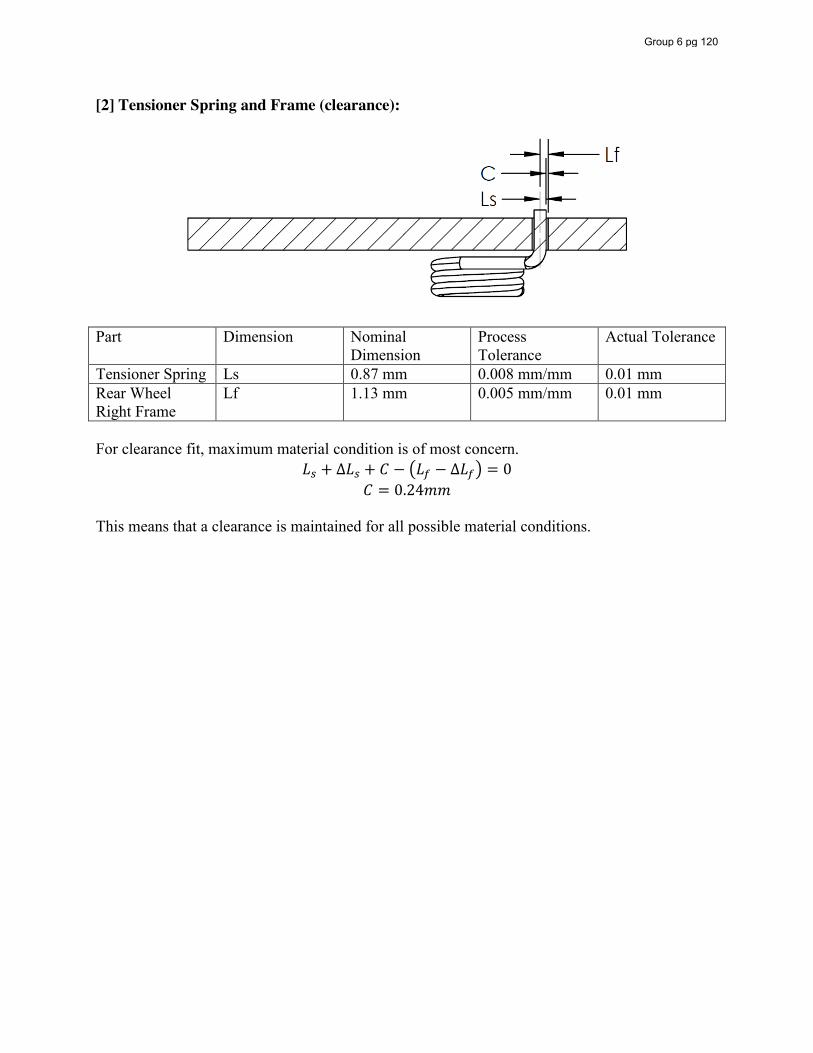
[2] Tensioner Spring and Frame (clearance):
Part Dimension Nominal
Dimension Process Tolerance
Actual Tolerance
Tensioner Spring Ls 0.87 mm 0.008 mm/mm 0.01 mm Rear Wheel Right Frame
Lf 1.13 mm 0.005 mm/mm 0.01 mm
For clearance fit, maximum material condition is of most concern.
𝐿 + ∆𝐿 + 𝐶 − 𝐿 − ∆𝐿 = 0 𝐶 = 0.24𝑚𝑚
This means that a clearance is maintained for all possible material conditions.
Group 6 pg 120
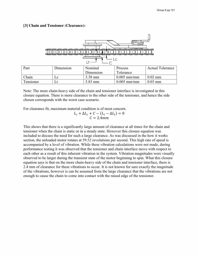
[3] Chain and Tensioner (Clearance):
Part Dimension Nominal
Dimension Process Tolerance
Actual Tolerance
Chain Lc 3.38 mm 0.005 mm/mm 0.02 mm Tensioner Lt 5.83 mm 0.005 mm/mm 0.03 mm Note: The more chain-heavy side of the chain and tensioner interface is investigated in this closure equation. There is more clearance to the other side of the tensioner, and hence the side chosen corresponds with the worst case scenario. For clearance fit, maximum material condition is of most concern.
𝐿 + ∆𝐿 + 𝐶 − (𝐿 − ∆𝐿 ) = 0 𝐶 = 2.4𝑚𝑚
This shows that there is a significantly large amount of clearance at all times for the chain and tensioner when the chain is static or in a steady state. However this closure equation was included to discuss the need for such a large clearance. As was discussed in the how it works section, the unloaded motor rotates at 59.52 revolutions per second. This high rate of speed is accompanied by a level of vibration. While these vibration calculations were not made, during performance testing it was observed that the tensioner and chain interface move with respect to each other as a result of this inherent vibration in the system. Vibration magnitudes were visually observed to be larger during the transient state of the motor beginning to spin. What this closure equation says is that on the more chain-heavy side of the chain and tensioner interface, there is 2.4 mm of clearance for these vibrations to occur. It is not known for sure exactly the magnitude of the vibrations, however is can be assumed from the large clearance that the vibrations are not enough to cause the chain to come into contact with the raised edge of the tensioner.
Group 6 pg 121
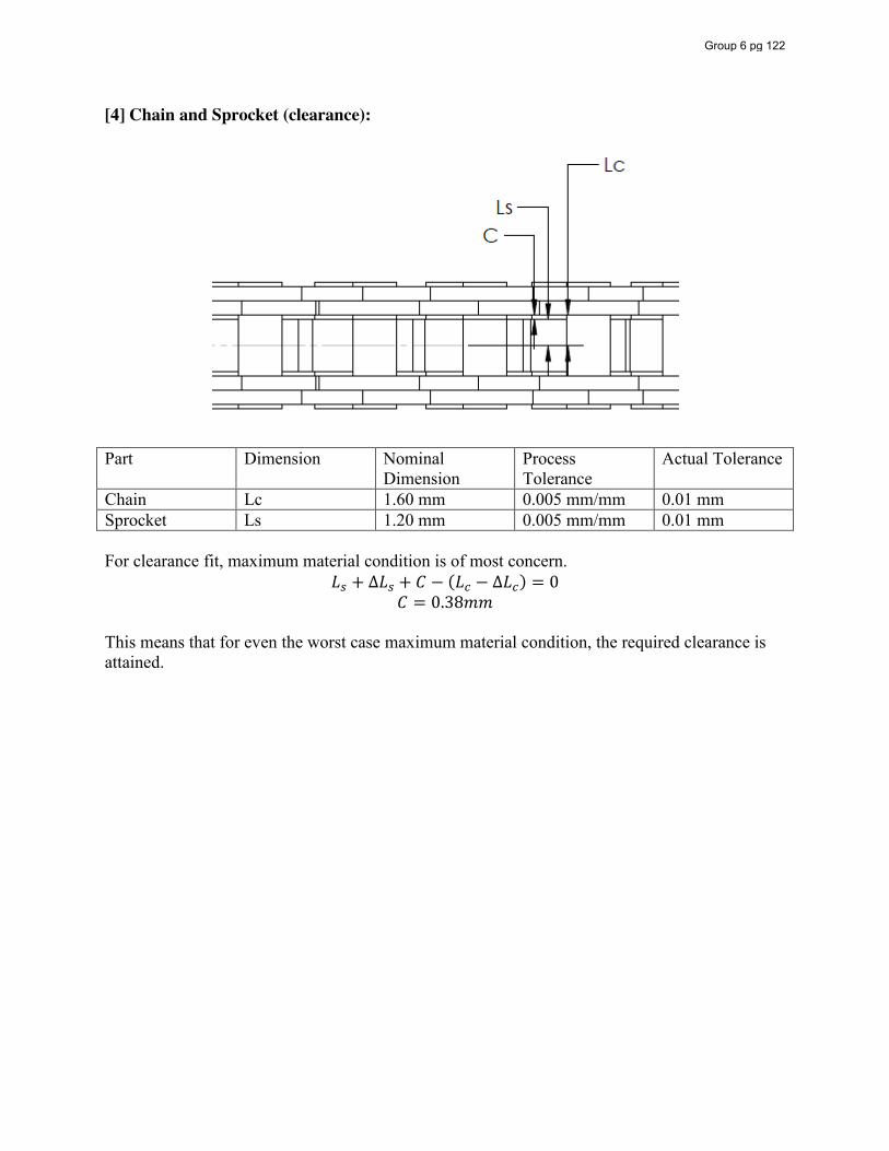
[4] Chain and Sprocket (clearance):
Part Dimension Nominal
Dimension Process Tolerance
Actual Tolerance
Chain Lc 1.60 mm 0.005 mm/mm 0.01 mm Sprocket Ls 1.20 mm 0.005 mm/mm 0.01 mm For clearance fit, maximum material condition is of most concern.
𝐿 + ∆𝐿 + 𝐶 − (𝐿 − ∆𝐿 ) = 0 𝐶 = 0.38𝑚𝑚
This means that for even the worst case maximum material condition, the required clearance is attained.
Group 6 pg 122
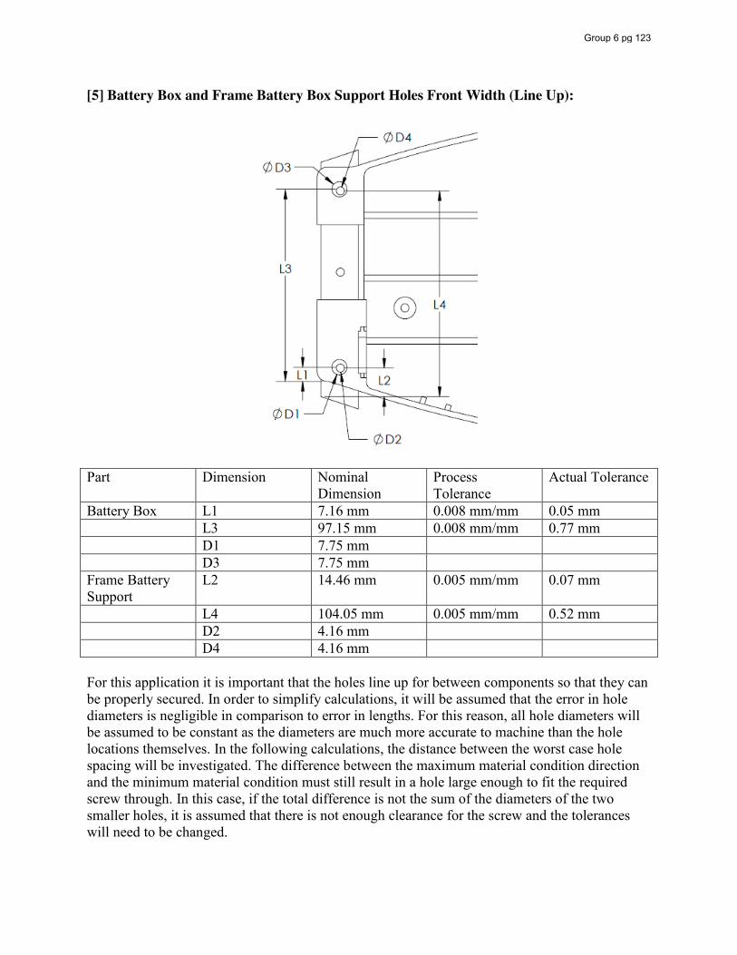
[5] Battery Box and Frame Battery Box Support Holes Front Width (Line Up):
Part Dimension Nominal Dimension
Process Tolerance
Actual Tolerance
Battery Box L1 7.16 mm 0.008 mm/mm 0.05 mm L3 97.15 mm 0.008 mm/mm 0.77 mm D1 7.75 mm D3 7.75 mm Frame Battery Support
L2 14.46 mm 0.005 mm/mm 0.07 mm
L4 104.05 mm 0.005 mm/mm 0.52 mm D2 4.16 mm D4 4.16 mm For this application it is important that the holes line up for between components so that they can be properly secured. In order to simplify calculations, it will be assumed that the error in hole diameters is negligible in comparison to error in lengths. For this reason, all hole diameters will be assumed to be constant as the diameters are much more accurate to machine than the hole locations themselves. In the following calculations, the distance between the worst case hole spacing will be investigated. The difference between the maximum material condition direction and the minimum material condition must still result in a hole large enough to fit the required screw through. In this case, if the total difference is not the sum of the diameters of the two smaller holes, it is assumed that there is not enough clearance for the screw and the tolerances will need to be changed.
Group 6 pg 123
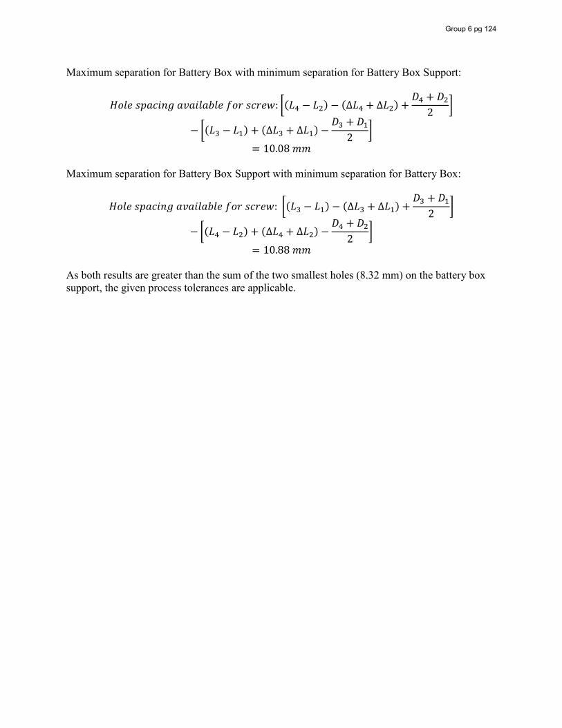
Maximum separation for Battery Box with minimum separation for Battery Box Support:
𝐻𝑜𝑙𝑒 𝑠𝑝𝑎𝑐𝑖𝑛𝑔 𝑎𝑣𝑎𝑖𝑙𝑎𝑏𝑙𝑒 𝑓𝑜𝑟 𝑠𝑐𝑟𝑒𝑤: (𝐿 − 𝐿 ) − (∆𝐿 + ∆𝐿 ) +𝐷 + 𝐷
2
− (𝐿 − 𝐿 ) + (∆𝐿 + ∆𝐿 ) −𝐷 + 𝐷
2
= 10.08 𝑚𝑚 Maximum separation for Battery Box Support with minimum separation for Battery Box:
𝐻𝑜𝑙𝑒 𝑠𝑝𝑎𝑐𝑖𝑛𝑔 𝑎𝑣𝑎𝑖𝑙𝑎𝑏𝑙𝑒 𝑓𝑜𝑟 𝑠𝑐𝑟𝑒𝑤: (𝐿 − 𝐿 ) − (∆𝐿 + ∆𝐿 ) +𝐷 + 𝐷
2
− (𝐿 − 𝐿 ) + (∆𝐿 + ∆𝐿 ) −𝐷 + 𝐷
2
= 10.88 𝑚𝑚 As both results are greater than the sum of the two smallest holes (8.32 mm) on the battery box support, the given process tolerances are applicable.
Group 6 pg 124

[6] Battery Box and Frame Battery Box Support Holes Rear Width (Line Up):
Part Dimension Nominal
Dimension Process Tolerance
Actual Tolerance
Battery Box L1 11.86 mm 0.008 mm/mm 0.09 mm L3 144.00 mm 0.008 mm/mm 1.15 mm D1 7.75 mm D3 7.75 mm Frame Battery Support
L2 19.56 mm 0.005 mm/mm 0.09 mm
L4 150.56 mm 0.005 mm/mm 0.75 mm D2 4.95 mm D4 4.58 mm For this application it is important that the holes line up for between components so that they can be properly secured. In order to simplify calculations, it will be assumed that the error in hole diameters is negligible in comparison to error in lengths. For this reason, all hole diameters will be assumed to be constant as the diameters are much more accurate to machine than the hole locations themselves. In the following calculations, the distance between the worst case hole spacing will be investigated. The difference between the maximum material condition direction and the minimum material condition must still result in a hole large enough to fit the required screw through. In this case, if the total difference is not the sum of the diameters of the two smaller holes, it is assumed that there is not enough clearance for the screw and the tolerances will need to be changed.
Group 6 pg 125
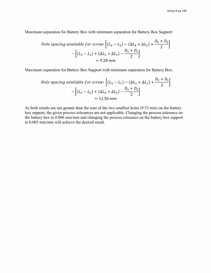
Maximum separation for Battery Box with minimum separation for Battery Box Support:
𝐻𝑜𝑙𝑒 𝑠𝑝𝑎𝑐𝑖𝑛𝑔 𝑎𝑣𝑎𝑖𝑙𝑎𝑏𝑙𝑒 𝑓𝑜𝑟 𝑠𝑐𝑟𝑒𝑤: (𝐿 − 𝐿 ) − (∆𝐿 + ∆𝐿 ) +𝐷 + 𝐷
2
− (𝐿 − 𝐿 ) + (∆𝐿 + ∆𝐿 ) −𝐷 + 𝐷
2
= 9.28 𝑚𝑚 Maximum separation for Battery Box Support with minimum separation for Battery Box:
𝐻𝑜𝑙𝑒 𝑠𝑝𝑎𝑐𝑖𝑛𝑔 𝑎𝑣𝑎𝑖𝑙𝑎𝑏𝑙𝑒 𝑓𝑜𝑟 𝑠𝑐𝑟𝑒𝑤: (𝐿 − 𝐿 ) − (∆𝐿 + ∆𝐿 ) +𝐷 + 𝐷
2
− (𝐿 − 𝐿 ) + (∆𝐿 + ∆𝐿 ) −𝐷 + 𝐷
2
= 11.56 𝑚𝑚 As both results are not greater than the sum of the two smallest holes (9.53 mm) on the battery box support, the given process tolerances are not applicable. Changing the process tolerance on the battery box to 0.006 mm/mm and changing the process tolerance on the battery box support to 0.003 mm/mm will achieve the desired result.
Group 6 pg 126
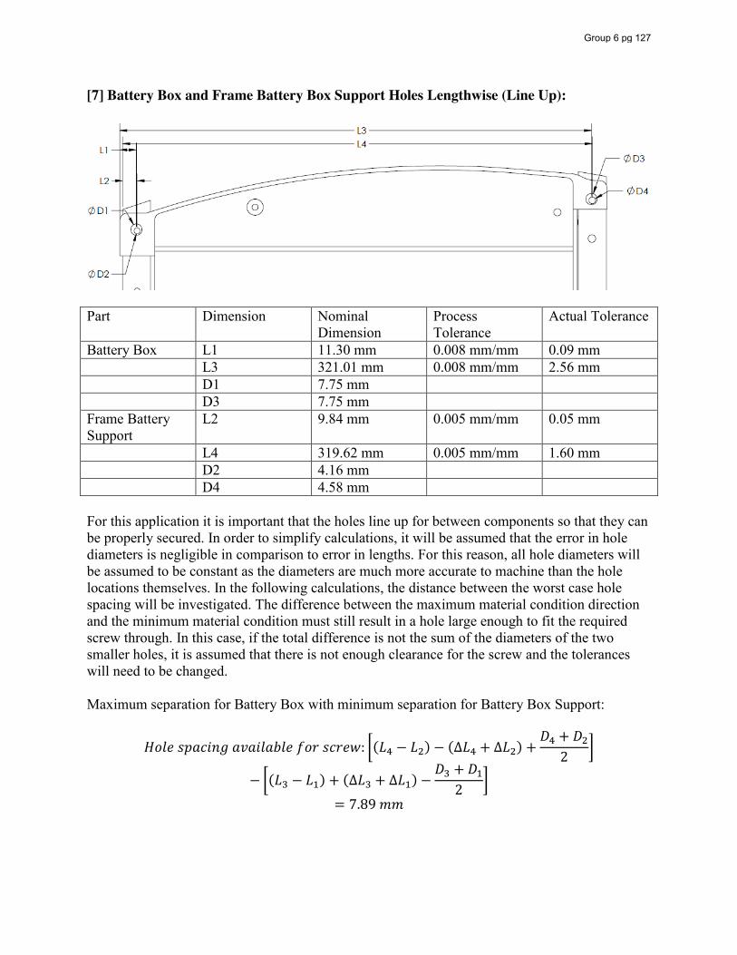
[7] Battery Box and Frame Battery Box Support Holes Lengthwise (Line Up):
Part Dimension Nominal
Dimension Process Tolerance
Actual Tolerance
Battery Box L1 11.30 mm 0.008 mm/mm 0.09 mm L3 321.01 mm 0.008 mm/mm 2.56 mm D1 7.75 mm D3 7.75 mm Frame Battery Support
L2 9.84 mm 0.005 mm/mm 0.05 mm
L4 319.62 mm 0.005 mm/mm 1.60 mm D2 4.16 mm D4 4.58 mm For this application it is important that the holes line up for between components so that they can be properly secured. In order to simplify calculations, it will be assumed that the error in hole diameters is negligible in comparison to error in lengths. For this reason, all hole diameters will be assumed to be constant as the diameters are much more accurate to machine than the hole locations themselves. In the following calculations, the distance between the worst case hole spacing will be investigated. The difference between the maximum material condition direction and the minimum material condition must still result in a hole large enough to fit the required screw through. In this case, if the total difference is not the sum of the diameters of the two smaller holes, it is assumed that there is not enough clearance for the screw and the tolerances will need to be changed. Maximum separation for Battery Box with minimum separation for Battery Box Support:
𝐻𝑜𝑙𝑒 𝑠𝑝𝑎𝑐𝑖𝑛𝑔 𝑎𝑣𝑎𝑖𝑙𝑎𝑏𝑙𝑒 𝑓𝑜𝑟 𝑠𝑐𝑟𝑒𝑤: (𝐿 − 𝐿 ) − (∆𝐿 + ∆𝐿 ) +𝐷 + 𝐷
2
− (𝐿 − 𝐿 ) + (∆𝐿 + ∆𝐿 ) −𝐷 + 𝐷
2
= 7.89 𝑚𝑚
Group 6 pg 127
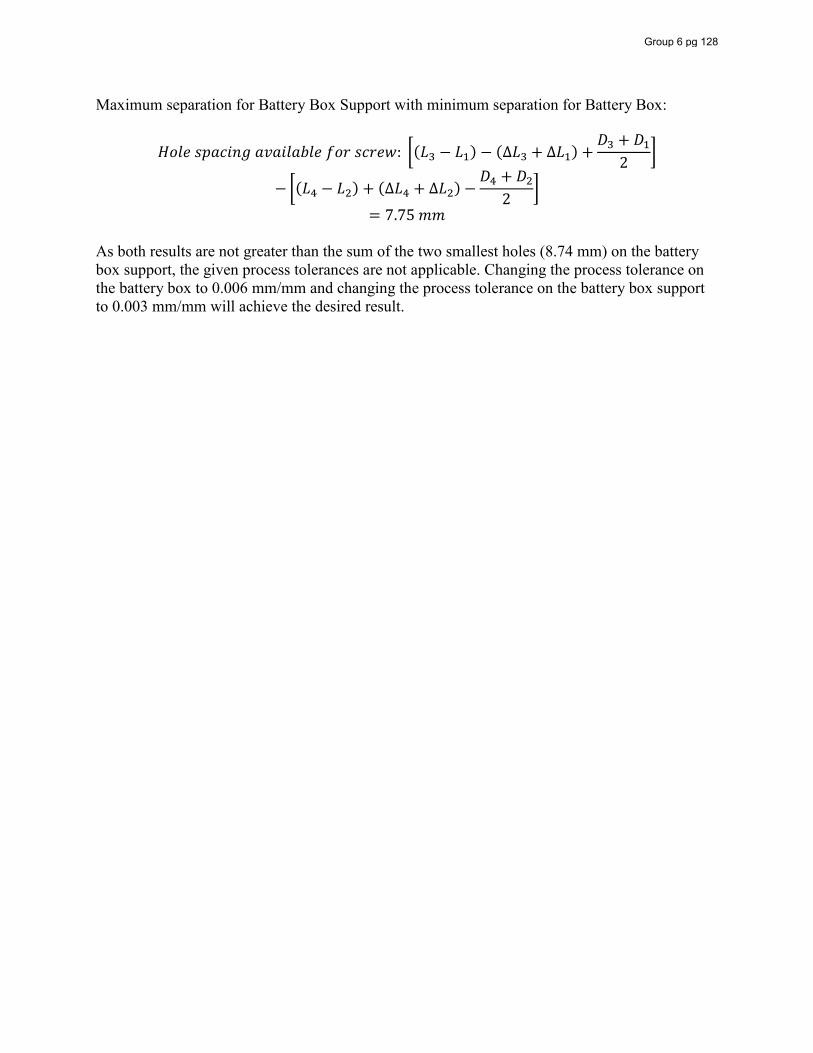
Maximum separation for Battery Box Support with minimum separation for Battery Box:
𝐻𝑜𝑙𝑒 𝑠𝑝𝑎𝑐𝑖𝑛𝑔 𝑎𝑣𝑎𝑖𝑙𝑎𝑏𝑙𝑒 𝑓𝑜𝑟 𝑠𝑐𝑟𝑒𝑤: (𝐿 − 𝐿 ) − (∆𝐿 + ∆𝐿 ) +𝐷 + 𝐷
2
− (𝐿 − 𝐿 ) + (∆𝐿 + ∆𝐿 ) −𝐷 + 𝐷
2
= 7.75 𝑚𝑚 As both results are not greater than the sum of the two smallest holes (8.74 mm) on the battery box support, the given process tolerances are not applicable. Changing the process tolerance on the battery box to 0.006 mm/mm and changing the process tolerance on the battery box support to 0.003 mm/mm will achieve the desired result.
Group 6 pg 128
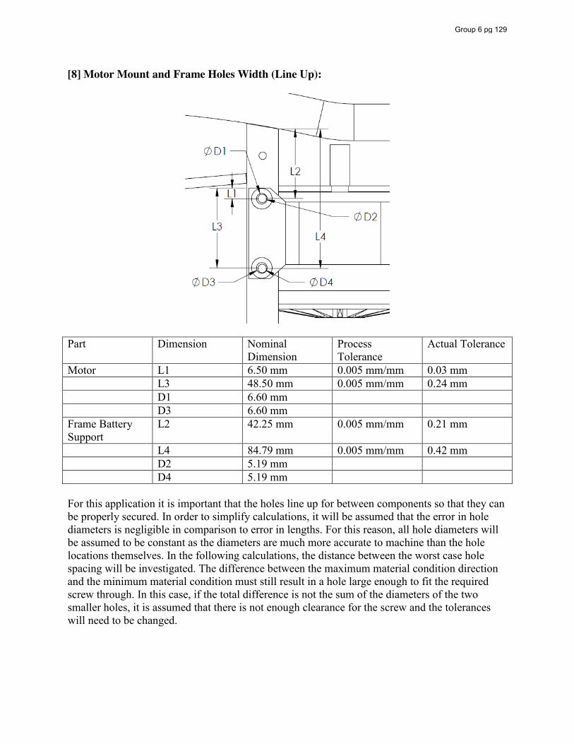
[8] Motor Mount and Frame Holes Width (Line Up):
Part Dimension Nominal
Dimension Process Tolerance
Actual Tolerance
Motor L1 6.50 mm 0.005 mm/mm 0.03 mm L3 48.50 mm 0.005 mm/mm 0.24 mm D1 6.60 mm D3 6.60 mm Frame Battery Support
L2 42.25 mm 0.005 mm/mm 0.21 mm
L4 84.79 mm 0.005 mm/mm 0.42 mm D2 5.19 mm D4 5.19 mm For this application it is important that the holes line up for between components so that they can be properly secured. In order to simplify calculations, it will be assumed that the error in hole diameters is negligible in comparison to error in lengths. For this reason, all hole diameters will be assumed to be constant as the diameters are much more accurate to machine than the hole locations themselves. In the following calculations, the distance between the worst case hole spacing will be investigated. The difference between the maximum material condition direction and the minimum material condition must still result in a hole large enough to fit the required screw through. In this case, if the total difference is not the sum of the diameters of the two smaller holes, it is assumed that there is not enough clearance for the screw and the tolerances will need to be changed.
Group 6 pg 129
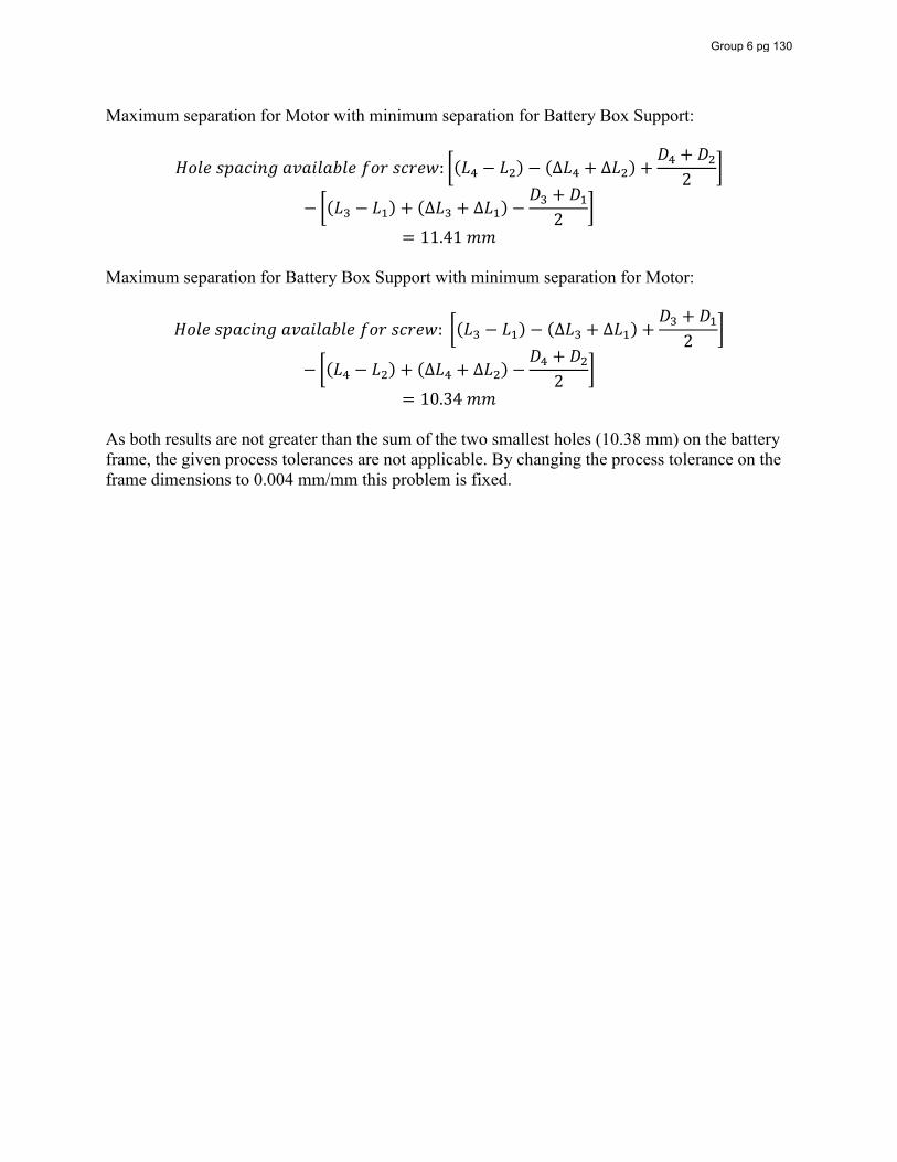
Maximum separation for Motor with minimum separation for Battery Box Support:
𝐻𝑜𝑙𝑒 𝑠𝑝𝑎𝑐𝑖𝑛𝑔 𝑎𝑣𝑎𝑖𝑙𝑎𝑏𝑙𝑒 𝑓𝑜𝑟 𝑠𝑐𝑟𝑒𝑤: (𝐿 − 𝐿 ) − (∆𝐿 + ∆𝐿 ) +𝐷 + 𝐷
2
− (𝐿 − 𝐿 ) + (∆𝐿 + ∆𝐿 ) −𝐷 + 𝐷
2
= 11.41 𝑚𝑚 Maximum separation for Battery Box Support with minimum separation for Motor:
𝐻𝑜𝑙𝑒 𝑠𝑝𝑎𝑐𝑖𝑛𝑔 𝑎𝑣𝑎𝑖𝑙𝑎𝑏𝑙𝑒 𝑓𝑜𝑟 𝑠𝑐𝑟𝑒𝑤: (𝐿 − 𝐿 ) − (∆𝐿 + ∆𝐿 ) +𝐷 + 𝐷
2
− (𝐿 − 𝐿 ) + (∆𝐿 + ∆𝐿 ) −𝐷 + 𝐷
2
= 10.34 𝑚𝑚 As both results are not greater than the sum of the two smallest holes (10.38 mm) on the battery frame, the given process tolerances are not applicable. By changing the process tolerance on the frame dimensions to 0.004 mm/mm this problem is fixed.
Group 6 pg 130
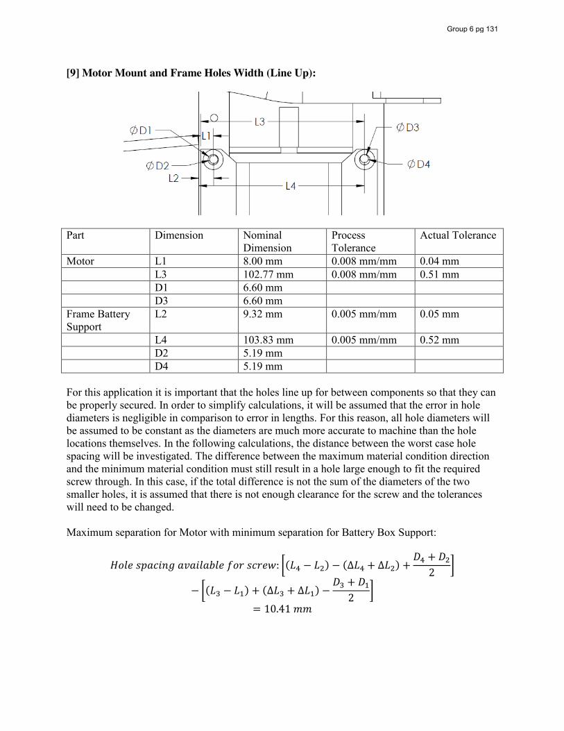
[9] Motor Mount and Frame Holes Width (Line Up):
Part Dimension Nominal
Dimension Process Tolerance
Actual Tolerance
Motor L1 8.00 mm 0.008 mm/mm 0.04 mm L3 102.77 mm 0.008 mm/mm 0.51 mm D1 6.60 mm D3 6.60 mm Frame Battery Support
L2 9.32 mm 0.005 mm/mm 0.05 mm
L4 103.83 mm 0.005 mm/mm 0.52 mm D2 5.19 mm D4 5.19 mm For this application it is important that the holes line up for between components so that they can be properly secured. In order to simplify calculations, it will be assumed that the error in hole diameters is negligible in comparison to error in lengths. For this reason, all hole diameters will be assumed to be constant as the diameters are much more accurate to machine than the hole locations themselves. In the following calculations, the distance between the worst case hole spacing will be investigated. The difference between the maximum material condition direction and the minimum material condition must still result in a hole large enough to fit the required screw through. In this case, if the total difference is not the sum of the diameters of the two smaller holes, it is assumed that there is not enough clearance for the screw and the tolerances will need to be changed. Maximum separation for Motor with minimum separation for Battery Box Support:
𝐻𝑜𝑙𝑒 𝑠𝑝𝑎𝑐𝑖𝑛𝑔 𝑎𝑣𝑎𝑖𝑙𝑎𝑏𝑙𝑒 𝑓𝑜𝑟 𝑠𝑐𝑟𝑒𝑤: (𝐿 − 𝐿 ) − (∆𝐿 + ∆𝐿 ) +𝐷 + 𝐷
2
− (𝐿 − 𝐿 ) + (∆𝐿 + ∆𝐿 ) −𝐷 + 𝐷
2
= 10.41 𝑚𝑚
Group 6 pg 131
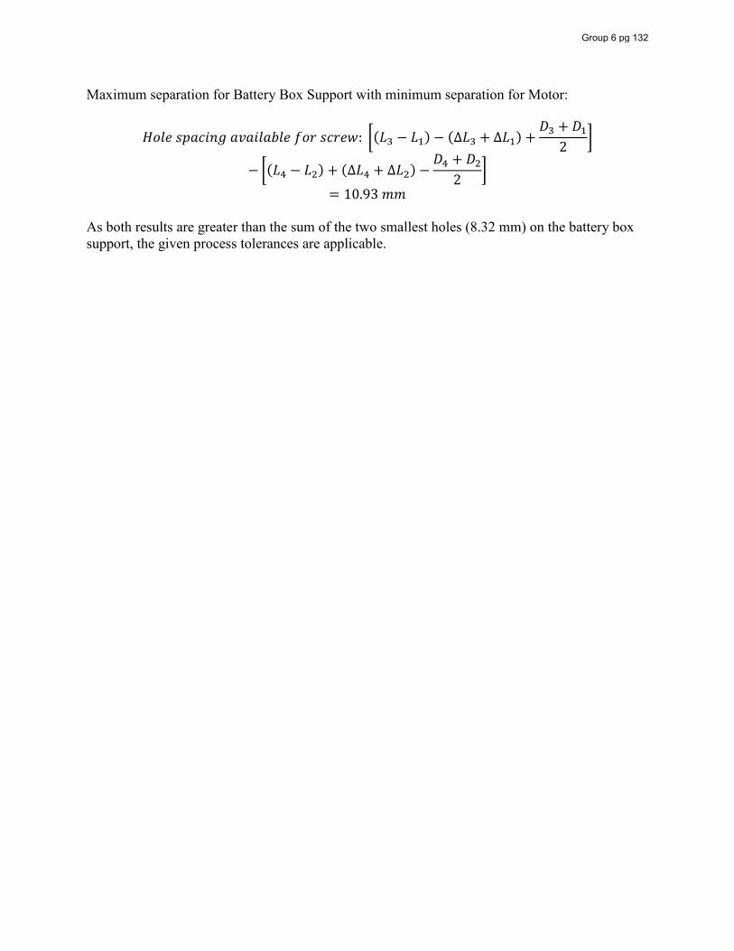
Maximum separation for Battery Box Support with minimum separation for Motor:
𝐻𝑜𝑙𝑒 𝑠𝑝𝑎𝑐𝑖𝑛𝑔 𝑎𝑣𝑎𝑖𝑙𝑎𝑏𝑙𝑒 𝑓𝑜𝑟 𝑠𝑐𝑟𝑒𝑤: (𝐿 − 𝐿 ) − (∆𝐿 + ∆𝐿 ) +𝐷 + 𝐷
2
− (𝐿 − 𝐿 ) + (∆𝐿 + ∆𝐿 ) −𝐷 + 𝐷
2
= 10.93 𝑚𝑚 As both results are greater than the sum of the two smallest holes (8.32 mm) on the battery box support, the given process tolerances are applicable.
Group 6 pg 132
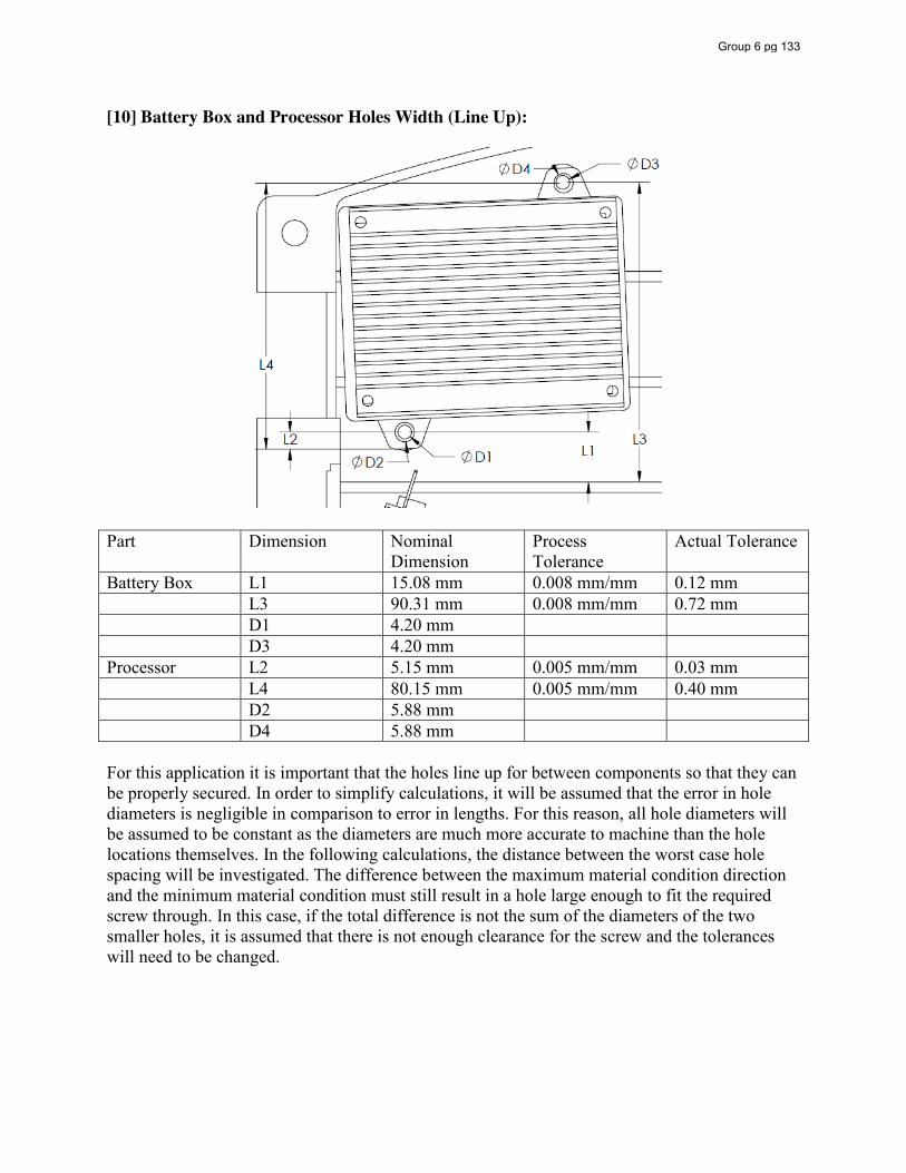
[10] Battery Box and Processor Holes Width (Line Up):
Part Dimension Nominal
Dimension Process Tolerance
Actual Tolerance
Battery Box L1 15.08 mm 0.008 mm/mm 0.12 mm L3 90.31 mm 0.008 mm/mm 0.72 mm D1 4.20 mm D3 4.20 mm Processor L2 5.15 mm 0.005 mm/mm 0.03 mm L4 80.15 mm 0.005 mm/mm 0.40 mm D2 5.88 mm D4 5.88 mm For this application it is important that the holes line up for between components so that they can be properly secured. In order to simplify calculations, it will be assumed that the error in hole diameters is negligible in comparison to error in lengths. For this reason, all hole diameters will be assumed to be constant as the diameters are much more accurate to machine than the hole locations themselves. In the following calculations, the distance between the worst case hole spacing will be investigated. The difference between the maximum material condition direction and the minimum material condition must still result in a hole large enough to fit the required screw through. In this case, if the total difference is not the sum of the diameters of the two smaller holes, it is assumed that there is not enough clearance for the screw and the tolerances will need to be changed.
Group 6 pg 133

Maximum separation for Battery Box with minimum separation for Processor:
𝐻𝑜𝑙𝑒 𝑠𝑝𝑎𝑐𝑖𝑛𝑔 𝑎𝑣𝑎𝑖𝑙𝑎𝑏𝑙𝑒 𝑓𝑜𝑟 𝑠𝑐𝑟𝑒𝑤: (𝐿 − 𝐿 ) − (∆𝐿 + ∆𝐿 ) +𝐷 + 𝐷
2
− (𝐿 − 𝐿 ) + (∆𝐿 + ∆𝐿 ) −𝐷 + 𝐷
2
= 8.58 𝑚𝑚 Maximum separation for Processor with minimum separation for Battery Box:
𝐻𝑜𝑙𝑒 𝑠𝑝𝑎𝑐𝑖𝑛𝑔 𝑎𝑣𝑎𝑖𝑙𝑎𝑏𝑙𝑒 𝑓𝑜𝑟 𝑠𝑐𝑟𝑒𝑤: (𝐿 − 𝐿 ) − (∆𝐿 + ∆𝐿 ) +𝐷 + 𝐷
2
− (𝐿 − 𝐿 ) + (∆𝐿 + ∆𝐿 ) −𝐷 + 𝐷
2
= 9.04 𝑚𝑚 As both results are greater than the sum of the two smallest holes (8.40 mm) on the battery box, the given process tolerances are applicable.
Group 6 pg 134
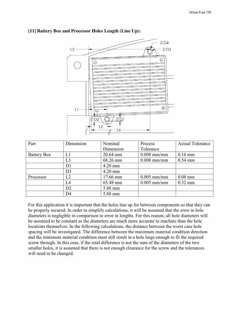
[11] Battery Box and Processor Holes Length (Line Up):
Part Dimension Nominal
Dimension Process Tolerance
Actual Tolerance
Battery Box L1 20.64 mm 0.008 mm/mm 0.16 mm L3 68.26 mm 0.008 mm/mm 0.54 mm D1 4.20 mm D3 4.20 mm Processor L2 17.66 mm 0.005 mm/mm 0.08 mm L4 65.48 mm 0.005 mm/mm 0.32 mm D2 5.88 mm D4 5.88 mm For this application it is important that the holes line up for between components so that they can be properly secured. In order to simplify calculations, it will be assumed that the error in hole diameters is negligible in comparison to error in lengths. For this reason, all hole diameters will be assumed to be constant as the diameters are much more accurate to machine than the hole locations themselves. In the following calculations, the distance between the worst case hole spacing will be investigated. The difference between the maximum material condition direction and the minimum material condition must still result in a hole large enough to fit the required screw through. In this case, if the total difference is not the sum of the diameters of the two smaller holes, it is assumed that there is not enough clearance for the screw and the tolerances will need to be changed.
Group 6 pg 135
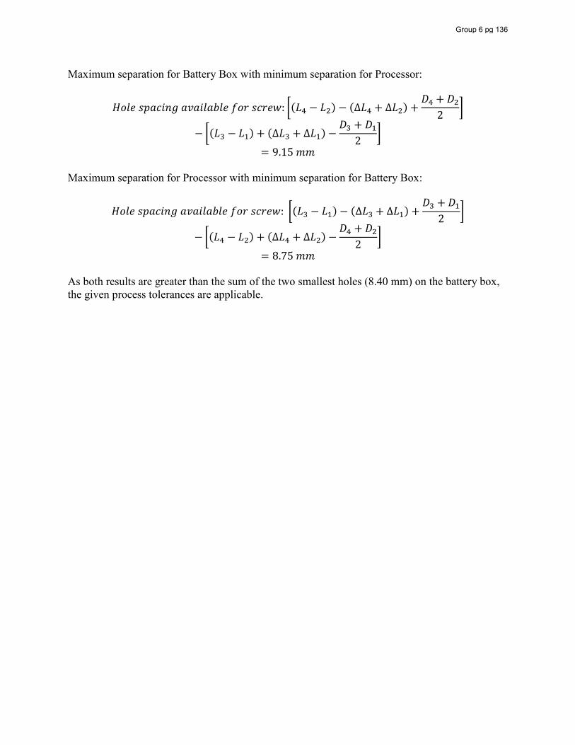
Maximum separation for Battery Box with minimum separation for Processor:
𝐻𝑜𝑙𝑒 𝑠𝑝𝑎𝑐𝑖𝑛𝑔 𝑎𝑣𝑎𝑖𝑙𝑎𝑏𝑙𝑒 𝑓𝑜𝑟 𝑠𝑐𝑟𝑒𝑤: (𝐿 − 𝐿 ) − (∆𝐿 + ∆𝐿 ) +𝐷 + 𝐷
2
− (𝐿 − 𝐿 ) + (∆𝐿 + ∆𝐿 ) −𝐷 + 𝐷
2
= 9.15 𝑚𝑚 Maximum separation for Processor with minimum separation for Battery Box:
𝐻𝑜𝑙𝑒 𝑠𝑝𝑎𝑐𝑖𝑛𝑔 𝑎𝑣𝑎𝑖𝑙𝑎𝑏𝑙𝑒 𝑓𝑜𝑟 𝑠𝑐𝑟𝑒𝑤: (𝐿 − 𝐿 ) − (∆𝐿 + ∆𝐿 ) +𝐷 + 𝐷
2
− (𝐿 − 𝐿 ) + (∆𝐿 + ∆𝐿 ) −𝐷 + 𝐷
2
= 8.75 𝑚𝑚 As both results are greater than the sum of the two smallest holes (8.40 mm) on the battery box, the given process tolerances are applicable.
Group 6 pg 136
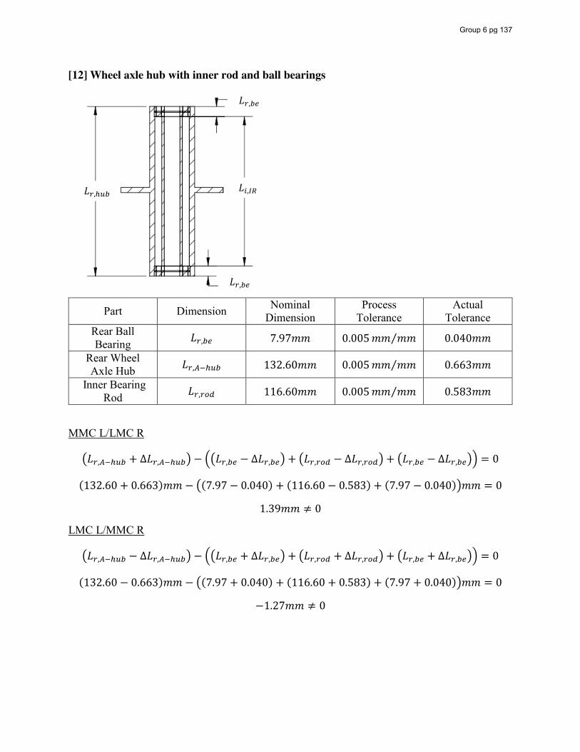
[12] Wheel axle hub with inner rod and ball bearings
Part Dimension Nominal Dimension
Process Tolerance
Actual Tolerance
Rear Ball Bearing 𝐿 , 7.97𝑚𝑚 0.005𝑚𝑚 𝑚𝑚⁄ 0.040𝑚𝑚
Rear Wheel Axle Hub 𝐿 , 132.60𝑚𝑚 0.005𝑚𝑚 𝑚𝑚⁄ 0.663𝑚𝑚
Inner Bearing Rod 𝐿 , 116.60𝑚𝑚 0.005𝑚𝑚 𝑚𝑚⁄ 0.583𝑚𝑚
MMC L/LMC R
𝐿 , + ∆𝐿 , − 𝐿 , − ∆𝐿 , + 𝐿 , − ∆𝐿 , + 𝐿 , − ∆𝐿 , = 0
(132.60 + 0.663)𝑚𝑚 − (7.97 − 0.040) + (116.60 − 0.583) + (7.97 − 0.040) 𝑚𝑚 = 0
1.39𝑚𝑚 ≠ 0
LMC L/MMC R
𝐿 , − ∆𝐿 , − 𝐿 , + ∆𝐿 , + 𝐿 , + ∆𝐿 , + 𝐿 , + ∆𝐿 , = 0
(132.60 − 0.663)𝑚𝑚 − (7.97 + 0.040) + (116.60 + 0.583) + (7.97 + 0.040) 𝑚𝑚 = 0
−1.27𝑚𝑚 ≠ 0
𝐿 ,
𝐿 ,
𝐿 , 𝐿 ,
Group 6 pg 137
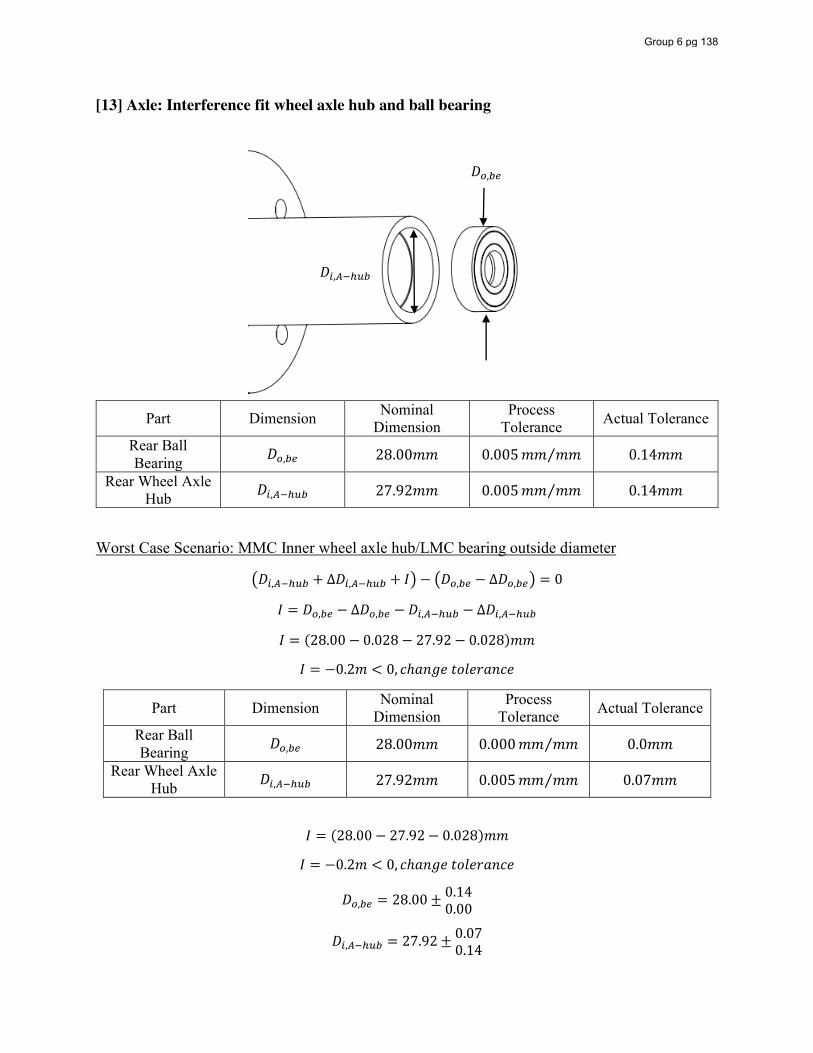
[13] Axle: Interference fit wheel axle hub and ball bearing
Part Dimension Nominal Dimension
Process Tolerance Actual Tolerance
Rear Ball Bearing 𝐷 , 28.00𝑚𝑚 0.005𝑚𝑚 𝑚𝑚⁄ 0.14𝑚𝑚
Rear Wheel Axle Hub 𝐷 , 27.92𝑚𝑚 0.005𝑚𝑚 𝑚𝑚⁄ 0.14𝑚𝑚
Worst Case Scenario: MMC Inner wheel axle hub/LMC bearing outside diameter
𝐷 , + ∆𝐷 , + 𝐼 − 𝐷 , − ∆𝐷 , = 0
𝐼 = 𝐷 , − ∆𝐷 , − 𝐷 , − ∆𝐷 ,
𝐼 = (28.00 − 0.028 − 27.92 − 0.028)𝑚𝑚
𝐼 = −0.2𝑚 < 0, 𝑐ℎ𝑎𝑛𝑔𝑒 𝑡𝑜𝑙𝑒𝑟𝑎𝑛𝑐𝑒
Part Dimension Nominal Dimension
Process Tolerance Actual Tolerance
Rear Ball Bearing 𝐷 , 28.00𝑚𝑚 0.000𝑚𝑚 𝑚𝑚⁄ 0.0𝑚𝑚
Rear Wheel Axle Hub 𝐷 , 27.92𝑚𝑚 0.005𝑚𝑚 𝑚𝑚⁄ 0.07𝑚𝑚
𝐼 = (28.00 − 27.92 − 0.028)𝑚𝑚
𝐼 = −0.2𝑚 < 0, 𝑐ℎ𝑎𝑛𝑔𝑒 𝑡𝑜𝑙𝑒𝑟𝑎𝑛𝑐𝑒
𝐷 , = 28.00 ± 0.140.00
𝐷 , = 27.92 ± 0.070.14
𝐷 ,
𝐷 ,
Group 6 pg 138
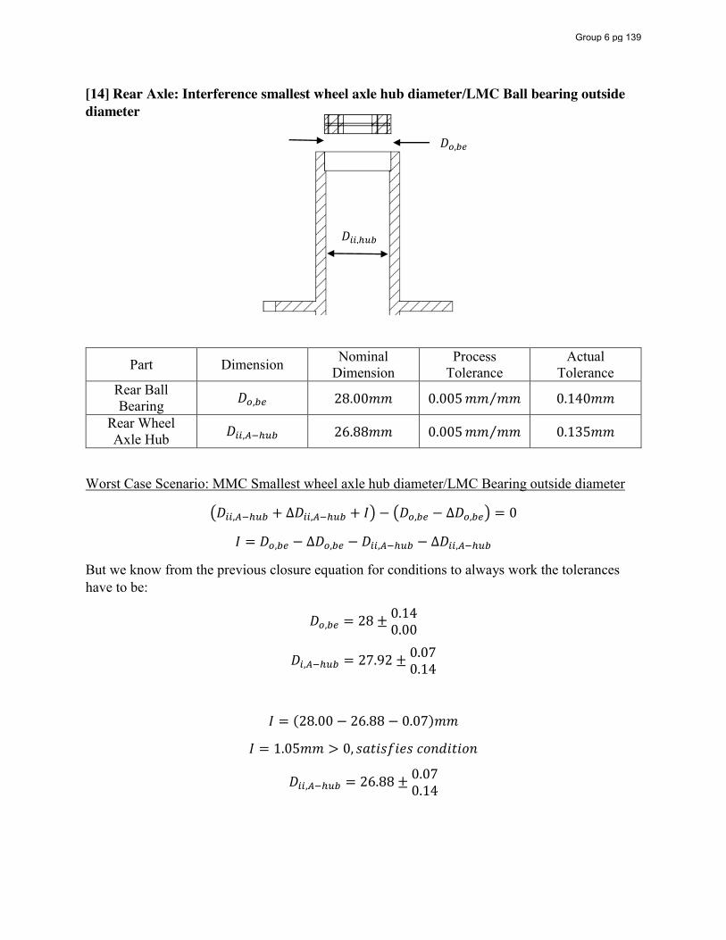
[14] Rear Axle: Interference smallest wheel axle hub diameter/LMC Ball bearing outside diameter
Part Dimension Nominal Dimension
Process Tolerance
Actual Tolerance
Rear Ball Bearing 𝐷 , 28.00𝑚𝑚 0.005𝑚𝑚 𝑚𝑚⁄ 0.140𝑚𝑚
Rear Wheel Axle Hub 𝐷 , 26.88𝑚𝑚 0.005𝑚𝑚 𝑚𝑚⁄ 0.135𝑚𝑚
Worst Case Scenario: MMC Smallest wheel axle hub diameter/LMC Bearing outside diameter
𝐷 , + ∆𝐷 , + 𝐼 − 𝐷 , − ∆𝐷 , = 0
𝐼 = 𝐷 , − ∆𝐷 , − 𝐷 , − ∆𝐷 ,
But we know from the previous closure equation for conditions to always work the tolerances have to be:
𝐷 , = 28 ± 0.140.00
𝐷 , = 27.92 ± 0.070.14
𝐼 = (28.00 − 26.88 − 0.07)𝑚𝑚
𝐼 = 1.05𝑚𝑚 > 0, 𝑠𝑎𝑡𝑖𝑠𝑓𝑖𝑒𝑠 𝑐𝑜𝑛𝑑𝑖𝑡𝑖𝑜𝑛
𝐷 , = 26.88 ± 0.070.14
𝐷 ,
𝐷 ,
Group 6 pg 139
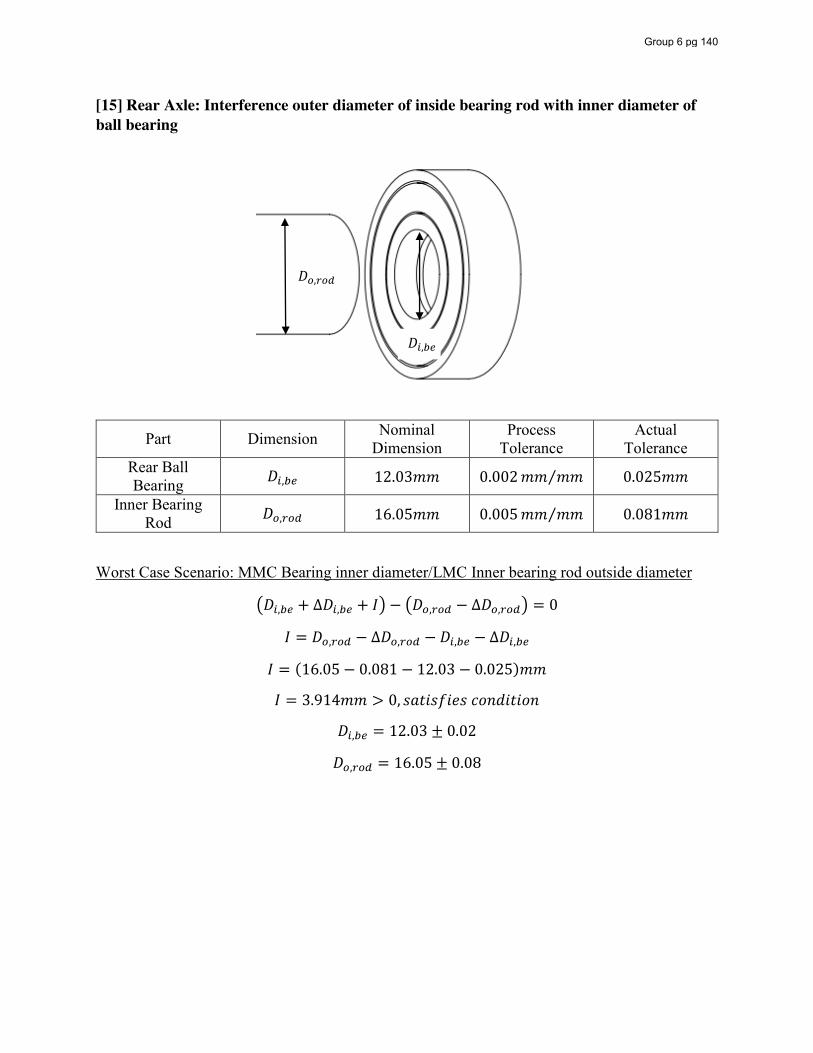
[15] Rear Axle: Interference outer diameter of inside bearing rod with inner diameter of ball bearing
Part Dimension Nominal Dimension
Process Tolerance
Actual Tolerance
Rear Ball Bearing 𝐷 , 12.03𝑚𝑚 0.002𝑚𝑚 𝑚𝑚⁄ 0.025𝑚𝑚
Inner Bearing Rod 𝐷 , 16.05𝑚𝑚 0.005𝑚𝑚 𝑚𝑚⁄ 0.081𝑚𝑚
Worst Case Scenario: MMC Bearing inner diameter/LMC Inner bearing rod outside diameter
𝐷 , + ∆𝐷 , + 𝐼 − 𝐷 , − ∆𝐷 , = 0
𝐼 = 𝐷 , − ∆𝐷 , − 𝐷 , − ∆𝐷 ,
𝐼 = (16.05 − 0.081 − 12.03 − 0.025)𝑚𝑚
𝐼 = 3.914𝑚𝑚 > 0, 𝑠𝑎𝑡𝑖𝑠𝑓𝑖𝑒𝑠 𝑐𝑜𝑛𝑑𝑖𝑡𝑖𝑜𝑛
𝐷 , = 12.03 ± 0.02
𝐷 , = 16.05 ± 0.08
𝐷 ,
𝐷 ,
Group 6 pg 140
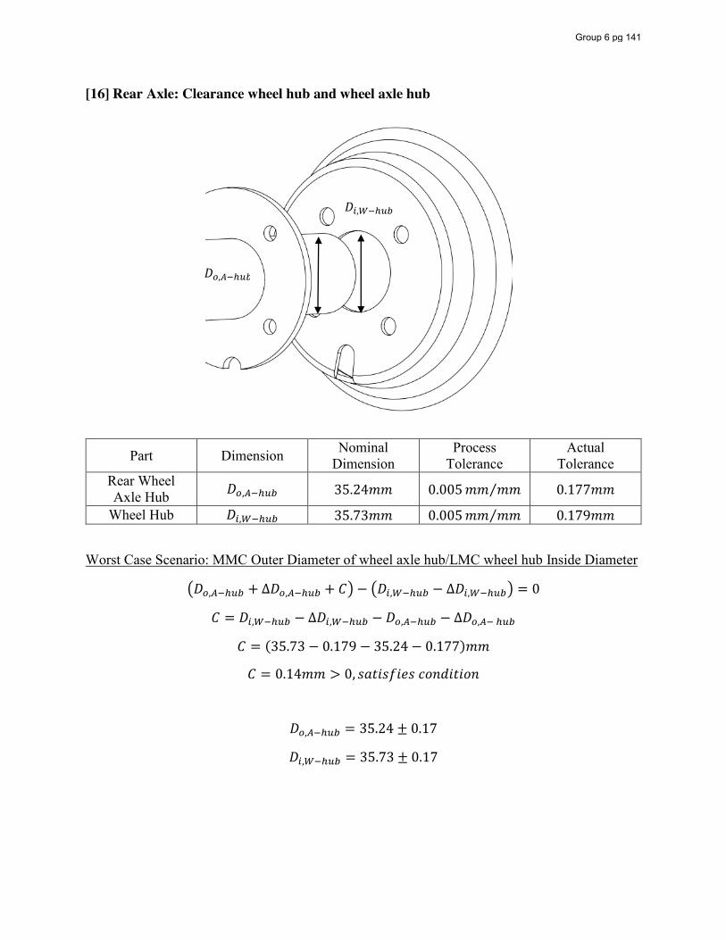
[16] Rear Axle: Clearance wheel hub and wheel axle hub
Part Dimension Nominal Dimension
Process Tolerance
Actual Tolerance
Rear Wheel Axle Hub 𝐷 , 35.24𝑚𝑚 0.005𝑚𝑚 𝑚𝑚⁄ 0.177𝑚𝑚
Wheel Hub 𝐷 , 35.73𝑚𝑚 0.005𝑚𝑚 𝑚𝑚⁄ 0.179𝑚𝑚
Worst Case Scenario: MMC Outer Diameter of wheel axle hub/LMC wheel hub Inside Diameter
𝐷 , + ∆𝐷 , + 𝐶 − 𝐷 , − ∆𝐷 , = 0
𝐶 = 𝐷 , − ∆𝐷 , − 𝐷 , − ∆𝐷 ,
𝐶 = (35.73 − 0.179 − 35.24 − 0.177)𝑚𝑚
𝐶 = 0.14𝑚𝑚 > 0, 𝑠𝑎𝑡𝑖𝑠𝑓𝑖𝑒𝑠 𝑐𝑜𝑛𝑑𝑖𝑡𝑖𝑜𝑛
𝐷 , = 35.24 ± 0.17
𝐷 , = 35.73 ± 0.17
𝐷 ,
𝐷 ,
Group 6 pg 141
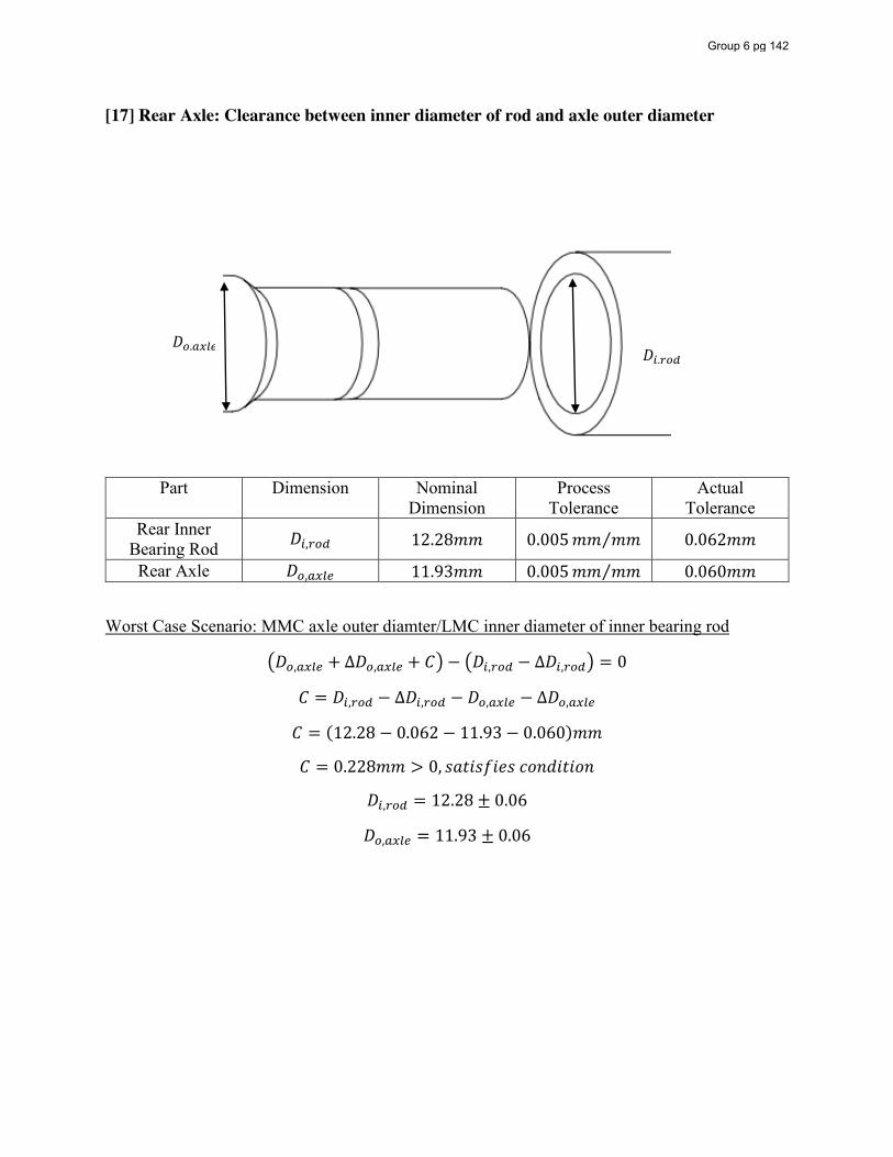
[17] Rear Axle: Clearance between inner diameter of rod and axle outer diameter
Part Dimension Nominal Dimension
Process Tolerance
Actual Tolerance
Rear Inner Bearing Rod 𝐷 , 12.28𝑚𝑚 0.005𝑚𝑚 𝑚𝑚⁄ 0.062𝑚𝑚
Rear Axle 𝐷 , 11.93𝑚𝑚 0.005𝑚𝑚 𝑚𝑚⁄ 0.060𝑚𝑚
Worst Case Scenario: MMC axle outer diamter/LMC inner diameter of inner bearing rod
𝐷 , + ∆𝐷 , + 𝐶 − 𝐷 , − ∆𝐷 , = 0
𝐶 = 𝐷 , − ∆𝐷 , − 𝐷 , − ∆𝐷 ,
𝐶 = (12.28 − 0.062 − 11.93 − 0.060)𝑚𝑚
𝐶 = 0.228𝑚𝑚 > 0, 𝑠𝑎𝑡𝑖𝑠𝑓𝑖𝑒𝑠 𝑐𝑜𝑛𝑑𝑖𝑡𝑖𝑜𝑛
𝐷 , = 12.28 ± 0.06
𝐷 , = 11.93 ± 0.06
𝐷 , 𝐷 ,
Group 6 pg 142
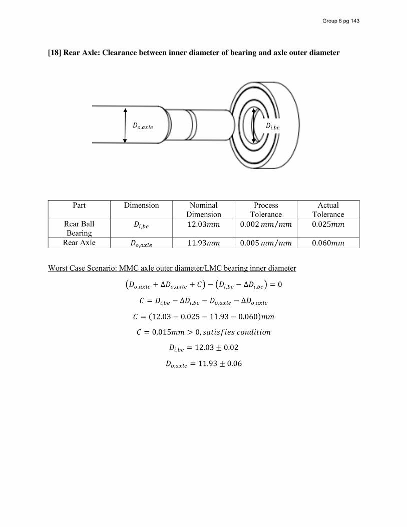
[18] Rear Axle: Clearance between inner diameter of bearing and axle outer diameter
Part Dimension Nominal Dimension
Process Tolerance
Actual Tolerance
Rear Ball Bearing
𝐷 , 12.03𝑚𝑚 0.002𝑚𝑚 𝑚𝑚⁄ 0.025𝑚𝑚
Rear Axle 𝐷 , 11.93𝑚𝑚 0.005𝑚𝑚 𝑚𝑚⁄ 0.060𝑚𝑚
Worst Case Scenario: MMC axle outer diameter/LMC bearing inner diameter
𝐷 , + ∆𝐷 , + 𝐶 − 𝐷 , − ∆𝐷 , = 0
𝐶 = 𝐷 , − ∆𝐷 , − 𝐷 , − ∆𝐷 ,
𝐶 = (12.03 − 0.025 − 11.93 − 0.060)𝑚𝑚
𝐶 = 0.015𝑚𝑚 > 0, 𝑠𝑎𝑡𝑖𝑠𝑓𝑖𝑒𝑠 𝑐𝑜𝑛𝑑𝑖𝑡𝑖𝑜𝑛
𝐷 , = 12.03 ± 0.02
𝐷 , = 11.93 ± 0.06
𝐷 , 𝐷 ,
Group 6 pg 143
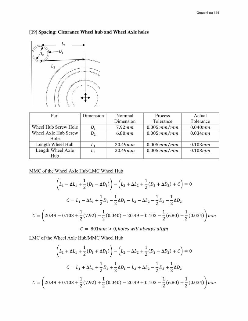
[19] Spacing: Clearance Wheel hub and Wheel Axle holes
Part Dimension Nominal Dimension
Process Tolerance
Actual Tolerance
Wheel Hub Screw Hole 𝐷 7.92𝑚𝑚 0.005𝑚𝑚 𝑚𝑚⁄ 0.040𝑚𝑚 Wheel Axle Hub Screw
Hole 𝐷 6.80𝑚𝑚 0.005𝑚𝑚 𝑚𝑚⁄ 0.034𝑚𝑚
Length Wheel Hub 𝐿 20.49𝑚𝑚 0.005𝑚𝑚 𝑚𝑚⁄ 0.103𝑚𝑚 Length Wheel Axle
Hub 𝐿 20.49𝑚𝑚 0.005𝑚𝑚 𝑚𝑚⁄ 0.103𝑚𝑚
MMC of the Wheel Axle Hub/LMC Wheel Hub
𝐿 − ∆𝐿 +12(𝐷 − ∆𝐷 ) − 𝐿 + ∆𝐿 +
12(𝐷 + ∆𝐷 ) + 𝐶 = 0
𝐶 = 𝐿 − ∆𝐿 +12𝐷 −
12∆𝐷 − 𝐿 − ∆𝐿 −
12𝐷 −
12∆𝐷
𝐶 = 20.49 − 0.103 +12(7.92) −
12(0.040) − 20.49 − 0.103 −
12(6.80) −
12(0.034) 𝑚𝑚
𝐶 = .801𝑚𝑚 > 0, ℎ𝑜𝑙𝑒𝑠 𝑤𝑖𝑙𝑙 𝑎𝑙𝑤𝑎𝑦𝑠 𝑎𝑙𝑖𝑔𝑛
LMC of the Wheel Axle Hub/MMC Wheel Hub
𝐿 + ∆𝐿 +12(𝐷 + ∆𝐷 ) − 𝐿 − ∆𝐿 +
12(𝐷 − ∆𝐷 ) + 𝐶 = 0
𝐶 = 𝐿 + ∆𝐿 +12𝐷 +
12∆𝐷 − 𝐿 + ∆𝐿 −
12𝐷 +
12∆𝐷
𝐶 = 20.49 + 0.103 +12(7.92) +
12(0.040) − 20.49 + 0.103 −
12(6.80) +
12(0.034) 𝑚𝑚
𝐷 𝐷
𝐿
𝐿
Group 6 pg 144
𝐶 = 0.803𝑚𝑚 > 0, ℎ𝑜𝑙𝑒𝑠 𝑤𝑖𝑙𝑙 𝑎𝑙𝑤𝑎𝑦𝑠 𝑎𝑙𝑖𝑔𝑛
𝐷 = 7.92 ± 0.04, 𝐷 = 6.80 ± 0.03, 𝐿 = 20.49 ± 0.10, 𝐿 = 20.49 ± 0.10
Group 6 pg 145
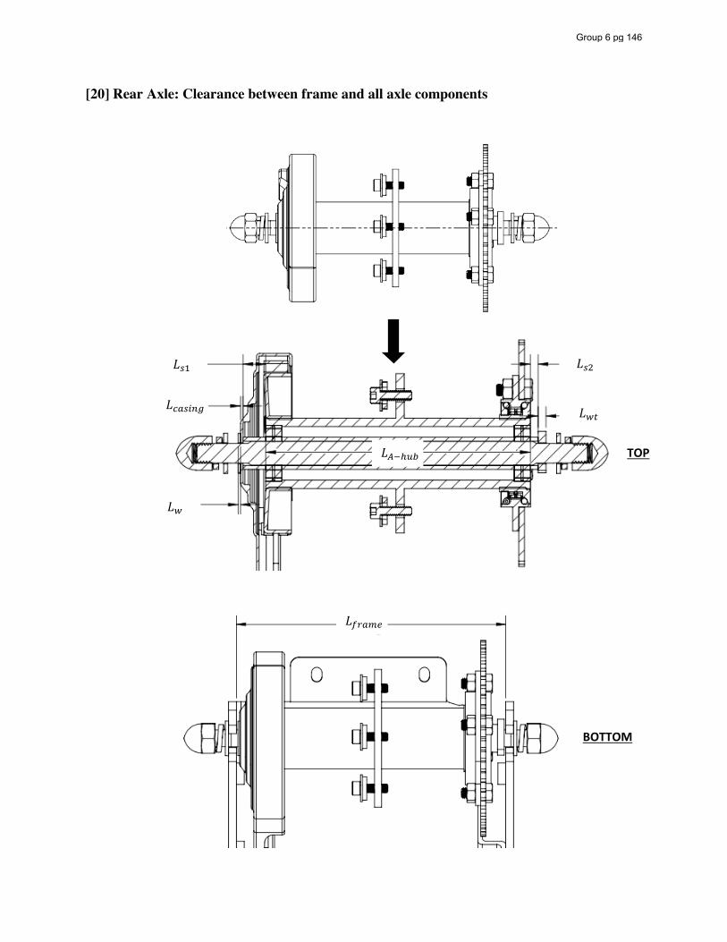
[20] Rear Axle: Clearance between frame and all axle components
𝐿
𝐿
𝐿
𝐿
𝐿
𝐿
𝐿
TOP
BOTTOM
Group 6 pg 146
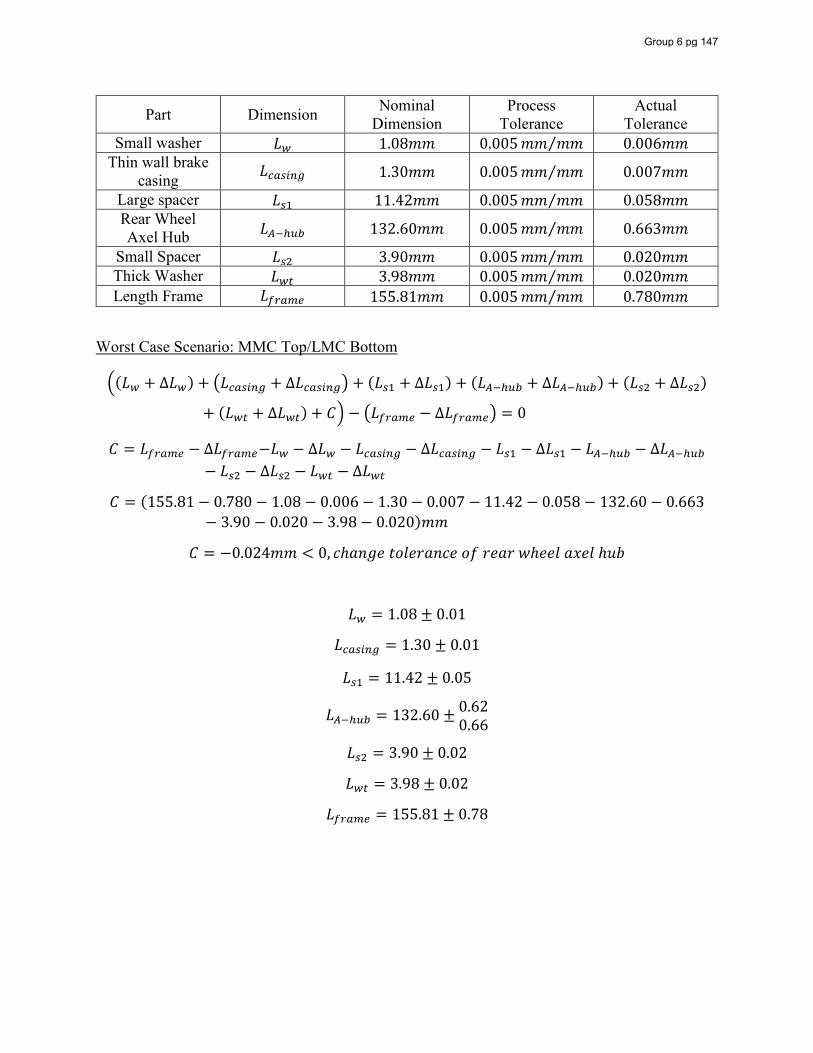
Part Dimension Nominal Dimension
Process Tolerance
Actual Tolerance
Small washer 𝐿 1.08𝑚𝑚 0.005𝑚𝑚 𝑚𝑚⁄ 0.006𝑚𝑚 Thin wall brake
casing 𝐿 1.30𝑚𝑚 0.005𝑚𝑚 𝑚𝑚⁄ 0.007𝑚𝑚
Large spacer 𝐿 11.42𝑚𝑚 0.005𝑚𝑚 𝑚𝑚⁄ 0.058𝑚𝑚 Rear Wheel Axel Hub 𝐿 132.60𝑚𝑚 0.005𝑚𝑚 𝑚𝑚⁄ 0.663𝑚𝑚
Small Spacer 𝐿 3.90𝑚𝑚 0.005𝑚𝑚 𝑚𝑚⁄ 0.020𝑚𝑚 Thick Washer 𝐿 3.98𝑚𝑚 0.005𝑚𝑚 𝑚𝑚⁄ 0.020𝑚𝑚 Length Frame 𝐿 155.81𝑚𝑚 0.005𝑚𝑚 𝑚𝑚⁄ 0.780𝑚𝑚
Worst Case Scenario: MMC Top/LMC Bottom
(𝐿 + ∆𝐿 ) + 𝐿 + ∆𝐿 + (𝐿 + ∆𝐿 ) + (𝐿 + ∆𝐿 ) + (𝐿 + ∆𝐿 )
+ (𝐿 + ∆𝐿 ) + 𝐶 − 𝐿 − ∆𝐿 = 0
𝐶 = 𝐿 − ∆𝐿 −𝐿 − ∆𝐿 − 𝐿 − ∆𝐿 − 𝐿 − ∆𝐿 − 𝐿 − ∆𝐿− 𝐿 − ∆𝐿 − 𝐿 − ∆𝐿
𝐶 = (155.81 − 0.780 − 1.08 − 0.006 − 1.30 − 0.007 − 11.42 − 0.058 − 132.60 − 0.663− 3.90 − 0.020 − 3.98 − 0.020)𝑚𝑚
𝐶 = −0.024𝑚𝑚 < 0, 𝑐ℎ𝑎𝑛𝑔𝑒 𝑡𝑜𝑙𝑒𝑟𝑎𝑛𝑐𝑒 𝑜𝑓 𝑟𝑒𝑎𝑟 𝑤ℎ𝑒𝑒𝑙 𝑎𝑥𝑒𝑙 ℎ𝑢𝑏
𝐿 = 1.08 ± 0.01
𝐿 = 1.30 ± 0.01
𝐿 = 11.42 ± 0.05
𝐿 = 132.60 ± 0.620.66
𝐿 = 3.90 ± 0.02
𝐿 = 3.98 ± 0.02
𝐿 = 155.81 ± 0.78
Group 6 pg 147
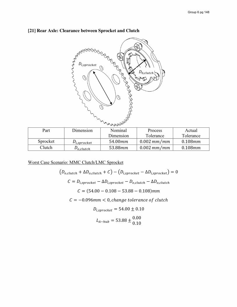
[21] Rear Axle: Clearance between Sprocket and Clutch
Part Dimension Nominal Dimension
Process Tolerance
Actual Tolerance
Sprocket 𝐷 , 54.00𝑚𝑚 0.002𝑚𝑚 𝑚𝑚⁄ 0.108𝑚𝑚 Clutch 𝐷 , 53.88𝑚𝑚 0.002𝑚𝑚 𝑚𝑚⁄ 0.108𝑚𝑚
Worst Case Scenario: MMC Clutch/LMC Sprocket
𝐷 , + ∆𝐷 , + 𝐶 − 𝐷 , − ∆𝐷 , = 0
𝐶 = 𝐷 , − ∆𝐷 , − 𝐷 , − ∆𝐷 ,
𝐶 = (54.00 − 0.108 − 53.88 − 0.108)𝑚𝑚
𝐶 = −0.096𝑚𝑚 < 0, 𝑐ℎ𝑎𝑛𝑔𝑒 𝑡𝑜𝑙𝑒𝑟𝑎𝑛𝑐𝑒 𝑜𝑓 𝑐𝑙𝑢𝑡𝑐ℎ
𝐷 , = 54.00 ± 0.10
𝐿 = 53.88 ± 0.000.10
𝐷 ,
𝐷 ,
Group 6 pg 148
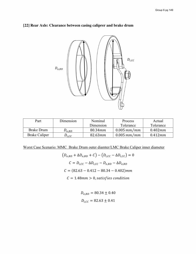
[22] Rear Axle: Clearance between casing caliprer and brake drum
Part Dimension Nominal Dimension
Process Tolerance
Actual Tolerance
Brake Drum 𝐷 , 80.34𝑚𝑚 0.005𝑚𝑚 𝑚𝑚⁄ 0.402𝑚𝑚 Brake Caliper 𝐷 , 82.63𝑚𝑚 0.005𝑚𝑚 𝑚𝑚⁄ 0.412𝑚𝑚
Worst Case Scenario: MMC Brake Drum outer diamter/LMC Brake Caliper inner diameter
𝐷 , + ∆𝐷 , + 𝐶 − 𝐷 , − ∆𝐷 , = 0
𝐶 = 𝐷 , − ∆𝐷 , − 𝐷 , − ∆𝐷 ,
𝐶 = (82.63 − 0.412 − 80.34 − 0.402)𝑚𝑚
𝐶 = 1.48𝑚𝑚 > 0, 𝑠𝑎𝑡𝑖𝑠𝑓𝑖𝑒𝑠 𝑐𝑜𝑛𝑑𝑖𝑡𝑖𝑜𝑛
𝐷 , = 80.34 ± 0.40
𝐷 , = 82.63 ± 0.41
𝐷 ,
𝐷 ,
Group 6 pg 149
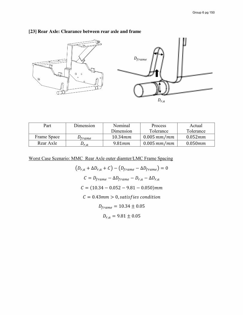
[23] Rear Axle: Clearance between rear axle and frame
Part Dimension Nominal Dimension
Process Tolerance
Actual Tolerance
Frame Space 𝐷 10.34𝑚𝑚 0.005𝑚𝑚 𝑚𝑚⁄ 0.052𝑚𝑚 Rear Axle 𝐷 , 9.81𝑚𝑚 0.005𝑚𝑚 𝑚𝑚⁄ 0.050𝑚𝑚
Worst Case Scenario: MMC Rear Axle outer diamter/LMC Frame Spacing
𝐷 , + ∆𝐷 , + 𝐶 − 𝐷 − ∆𝐷 = 0
𝐶 = 𝐷 − ∆𝐷 − 𝐷 , − ∆𝐷 ,
𝐶 = (10.34 − 0.052 − 9.81 − 0.050)𝑚𝑚
𝐶 = 0.43𝑚𝑚 > 0, 𝑠𝑎𝑡𝑖𝑠𝑓𝑖𝑒𝑠 𝑐𝑜𝑛𝑑𝑖𝑡𝑖𝑜𝑛
𝐷 = 10.34 ± 0.05
𝐷 , = 9.81 ± 0.05
𝐷
𝐷 ,
Group 6 pg 150

Appendix B:
Solidworks Drawings
Group 6 pg 151
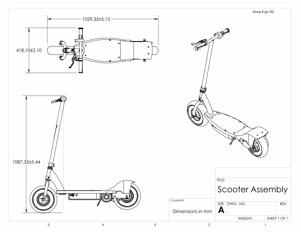
��������������
�������������
��������������
6FRRWHU�$VVHPEO\
6+((7���2)��:(,*+7��
5(9':*���12�
$6,=(
7,7/(�
&200(176�
� � � � �
'LPHQVLRQV�LQ�PP
Group 6 pg 152
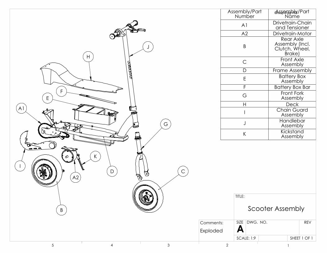
-
+
' &
*
%
$�
.
,
$�
()
$VVHPEO\�3DUW�1XPEHU
$VVHPEO\�3DUW�1DPH
$� 'ULYHWUDLQ�&KDLQ�DQG�7HQVLRQHU
$� 'ULYHWUDLQ�0RWRU
%5HDU�$[OH�
$VVHPEO\��,QFO��&OXWFK��:KHHO��
%UDNH�& )URQW�$[OH�
$VVHPEO\' )UDPH�$VVHPEO\( %DWWHU\�%R[�
$VVHPEO\) %DWWHU\�%R[�%DU* )URQW�)RUN�
$VVHPEO\+ 'HFN, &KDLQ�*XDUG�
$VVHPEO\- +DQGOHEDU�
$VVHPEO\. .LFNVWDQG�
$VVHPEO\
6+((7���2)��6&$/(�����
5(9':*���12�
$6,=(
7,7/(�
� � � � �
6FRRWHU�$VVHPEO\
&RPPHQWV�
([SORGHG
Group 6 pg 153
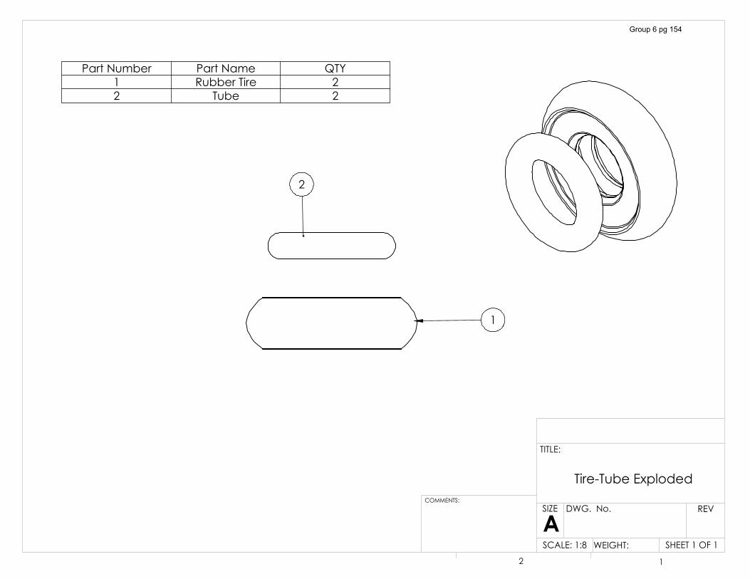
�
�
3DUW�1XPEHU 3DUW�1DPH 47<� 5XEEHU�7LUH �� 7XEH �
7LUH�7XEH�([SORGHG
6+((7���2)��6&$/(����� :(,*+7��
5(9':*���1R�
$� �
&200(176�
7,7/(�
6,=(
Group 6 pg 154
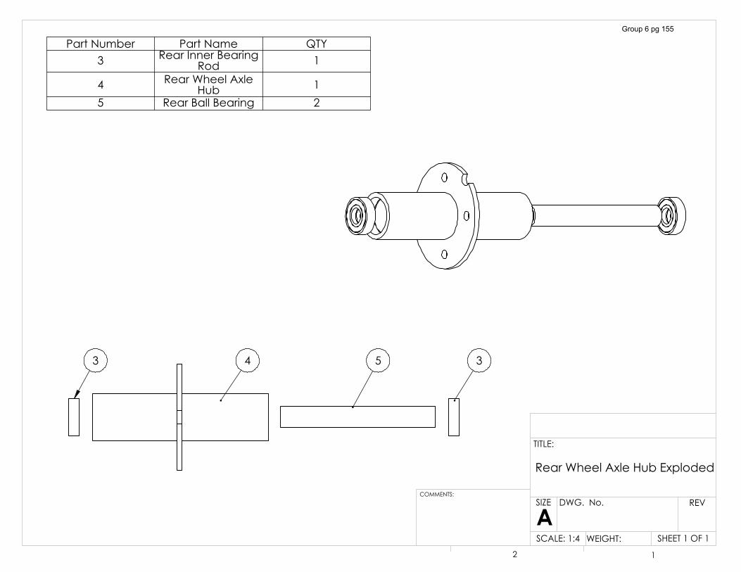
����
3DUW�1XPEHU 3DUW�1DPH 47<� 5HDU�,QQHU�%HDULQJ�
5RG �
� 5HDU�:KHHO�$[OH�+XE �
� 5HDU�%DOO�%HDULQJ �
5HDU�:KHHO�$[OH�+XE�([SORGHG
6+((7���2)��6&$/(����� :(,*+7��
5(9':*���1R�
$6,=(
7,7/(�
&200(176�
� �
Group 6 pg 155
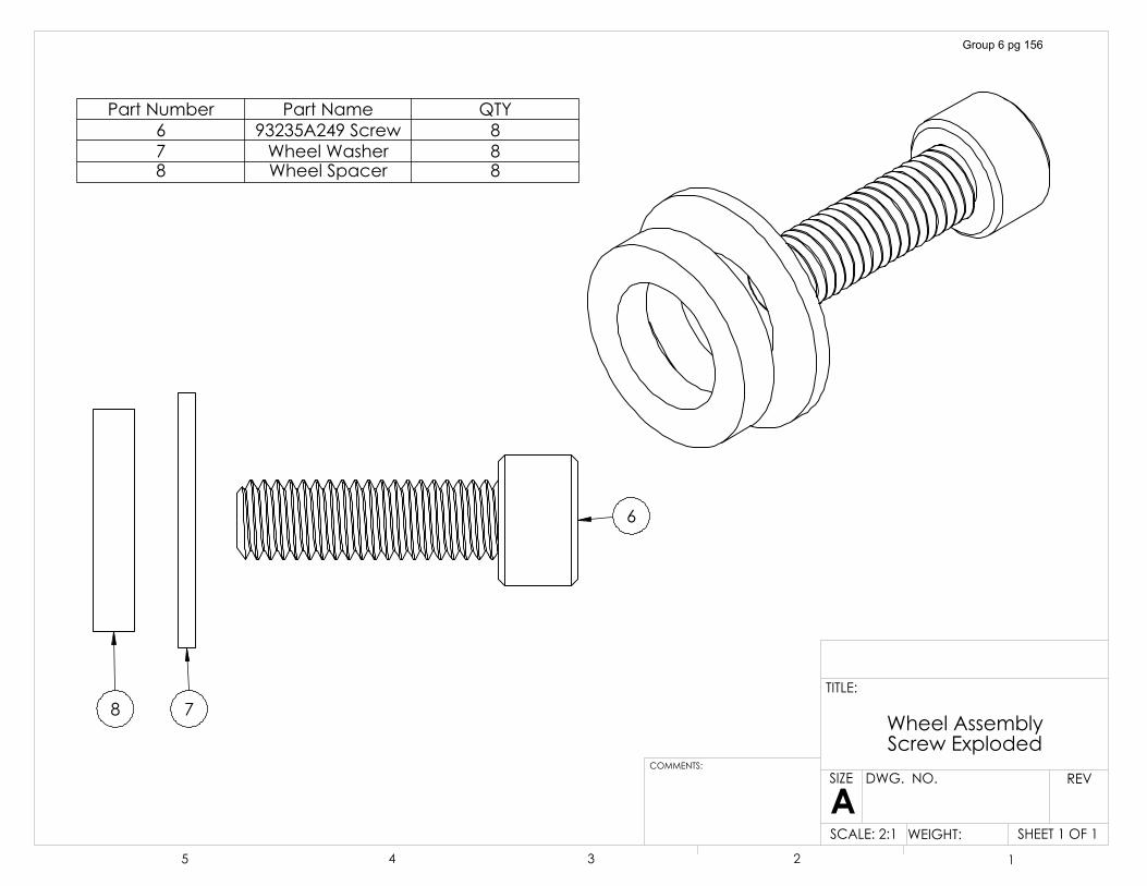
�
��
3DUW�1XPEHU 3DUW�1DPH 47<� �����$����6FUHZ �� :KHHO�:DVKHU �� :KHHO�6SDFHU �
:KHHO�$VVHPEO\�6FUHZ�([SORGHG
6+((7���2)��6&$/(����� :(,*+7��
5(9':*���12�
$6,=(
7,7/(�
&200(176�
� � � � �
Group 6 pg 156
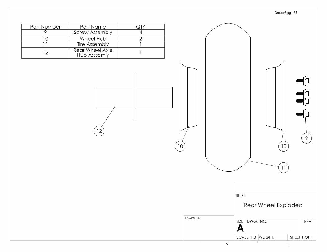
��
�� ���
��
3DUW�1XPEHU 3DUW�1DPH 47<� 6FUHZ�$VVHPEO\ ��� :KHHO�+XE ��� 7LUH�$VVHPEO\ ��� 5HDU�:KHHO�$[OH�
+XE�$VVVHPO\ �
5HDU�:KHHO�([SORGHG
6+((7���2)��6&$/(����� :(,*+7��
5(9':*���12�
$6,=(
7,7/(�
&200(176�
� �
Group 6 pg 157
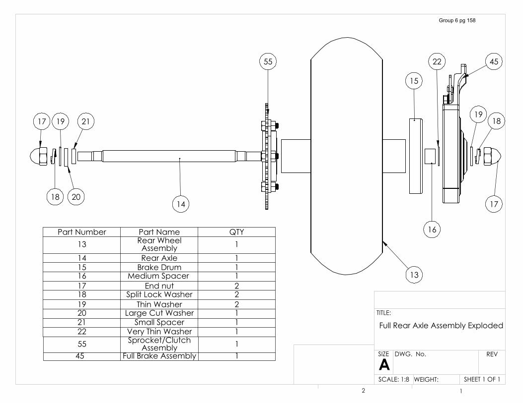
��
�� ��
����
����
��
��
��
��
��
��
��
��
3DUW�1XPEHU 3DUW�1DPH 47<�� 5HDU�:KHHO�
$VVHPEO\ �
�� 5HDU�$[OH ��� %UDNH�'UXP ��� 0HGLXP�6SDFHU� ��� (QG�QXW ��� 6SOLW�/RFN�:DVKHU ��� 7KLQ�:DVKHU ��� /DUJH�&XW�:DVKHU ��� 6PDOO�6SDFHU ��� 9HU\�7KLQ�:DVKHU ��� 6SURFNHW�&OXWFK�
$VVHPEO\ ����� )XOO�%UDNH�$VVHPEO\ �
)XOO�5HDU�$[OH�$VVHPEO\�([SORGHG
6+((7���2)��6&$/(����� :(,*+7��
5(9':*���1R�
$6,=(
7,7/(�
� �
Group 6 pg 158
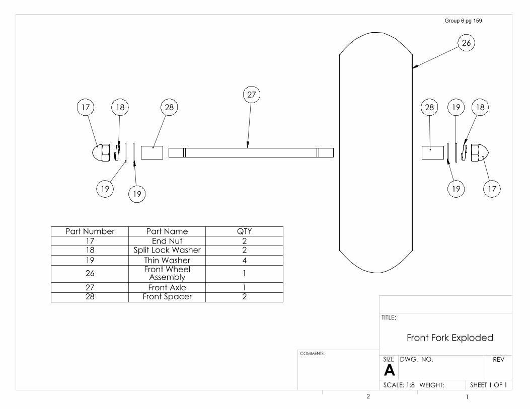
��
��
��
����
��
���� ��
�� ��
��
3DUW�1XPEHU 3DUW�1DPH 47<�� (QG�1XW ��� 6SOLW�/RFN�:DVKHU ��� 7KLQ�:DVKHU ��� )URQW�:KHHO�
$VVHPEO\ �
�� )URQW�$[OH ��� )URQW�6SDFHU �
)URQW�)RUN�([SORGHG
6+((7���2)��6&$/(����� :(,*+7��
5(9':*���12�
$6,=(
7,7/(�
&200(176�
� �
Group 6 pg 159
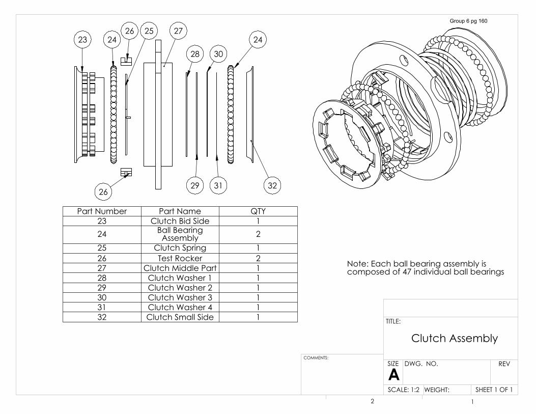
1RWH��(DFK�EDOO�EHDULQJ�DVVHPEO\�LV�FRPSRVHG�RI����LQGLYLGXDO�EDOO�EHDULQJV
�� ����
��
�� ��
��
��
��
��
��
��
3DUW�1XPEHU 3DUW�1DPH 47<�� &OXWFK�%LG�6LGH ��� %DOO�%HDULQJ�
$VVHPEO\ ��� &OXWFK�6SULQJ ��� 7HVW�5RFNHU ��� &OXWFK�0LGGOH�3DUW ��� &OXWFK�:DVKHU�� ��� &OXWFK�:DVKHU�� ��� &OXWFK�:DVKHU�� ��� &OXWFK�:DVKHU�� ��� &OXWFK�6PDOO�6LGH �
6+((7���2)��6&$/(����� :(,*+7��
5(9':*���12�
$6,=(
7,7/(�
&200(176�
� �
&OXWFK�$VVHPEO\
Group 6 pg 160
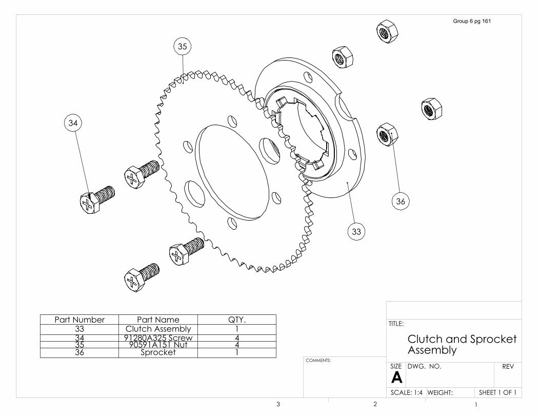
��
��
��
��
3DUW�1XPEHU 3DUW�1DPH 47<��� &OXWFK�$VVHPEO\ ��� �����$����6FUHZ ��� �����$����1XW ��� 6SURFNHW �
6+((7���2)��6&$/(����� :(,*+7��
5(9':*���12�
$6,=(
7,7/(�
&200(176�
� � �
&OXWFK�DQG�6SURFNHW�$VVHPEO\
Group 6 pg 161
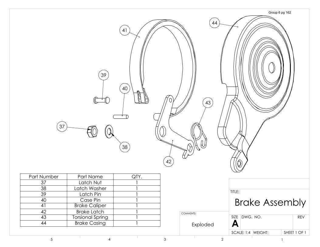
��
��
��
��
��
��
��
��
([SORGHG
3DUW�1XPEHU 3DUW�1DPH 47<��� /DWFK�1XW ��� /DWFK�:DVKHU ��� /DWFK�3LQ ��� &DVH�3LQ ��� %UDNH�&DOLSHU ��� %UDNH�/DWFK ��� 7RUVLRQDO�6SULQJ ��� %UDNH�&DVLQJ �
%UDNH�$VVHPEO\
6+((7���2)��6&$/(����� :(,*+7��
5(9':*���12�
$6,=(
7,7/(�
&200(176�
� � � � �
Group 6 pg 162
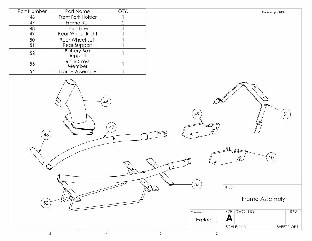
��
����
�� ��
��
��
��
3DUW�1XPEHU 3DUW�1DPH 47<��� )URQW�)RUN�+ROGHU ��� )UDPH�5DLO ��� )URQW�)LOOHU ��� 5HDU�:KHHO�5LJKW ��� 5HDU�:KHHO�/HIW ��� 5HDU�6XSSRUW ��� %DWWHU\�%R[�
6XSSRUW �
�� 5HDU�&URVV�0HPEHU �
�� )UDPH�$VVHPEO\ �
6+((7���2)��6&$/(������
5(9':*���12�
$6,=(
7,7/(�
� � � � �
)UDPH�$VVHPEO\
&RPPHQWV�
([SORGHG
Group 6 pg 163
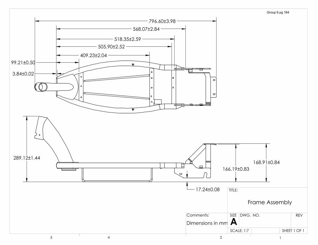
�������������
��������������������������
������������
�����������
�������������������������
��������������������������
��������������������������
6+((7���2)��6&$/(�����
5(9':*���12�
$6,=(
7,7/(�
� � � �
)UDPH�$VVHPEO\
&RPPHQWV�
'LPHQVLRQV�LQ�PP
Group 6 pg 164
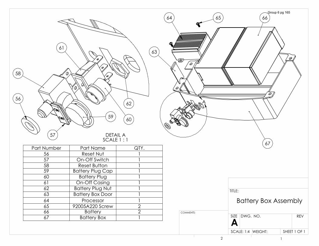
$
������
��
��
'(7$,/�$6&$/(������
��
��
��
�� ��
��
��
3DUW�1XPEHU 3DUW�1DPH 47<��� 5HVHW�1XW ��� 2Q�2II�6ZLWFK ��� 5HVHW�%XWWRQ ��� %DWWHU\�3OXJ�&DS ��� %DWWHU\�3OXJ ��� 2Q�2II�&DVLQJ ��� %DWWHU\�3OXJ�1XW ��� %DWWHU\�%R[�'RRU ��� 3URFHVVRU ��� �����$����6FUHZ ��� %DWWHU\ ��� %DWWHU\�%R[ �
6+((7���2)��6&$/(����� :(,*+7��
5(9':*���12�
$6,=(
7,7/(�
&200(176�
� �
%DWWHU\�%R[�$VVHPEO\
Group 6 pg 165
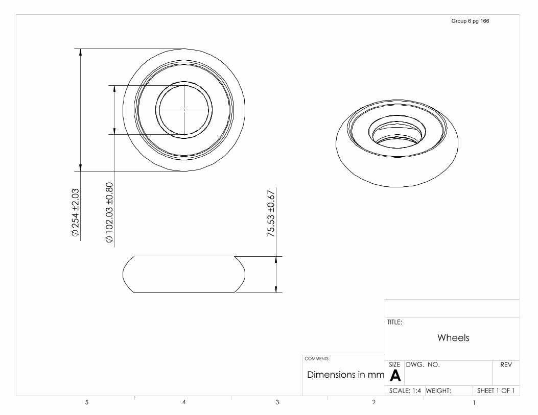
�������������
��������������
�����������
'LPHQVLRQV�LQ�PP
:KHHOV
6+((7���2)��6&$/(����� :(,*+7��
5(9':*���12�
$6,=(
7,7/(�
&200(176�
� � � � �
Group 6 pg 166
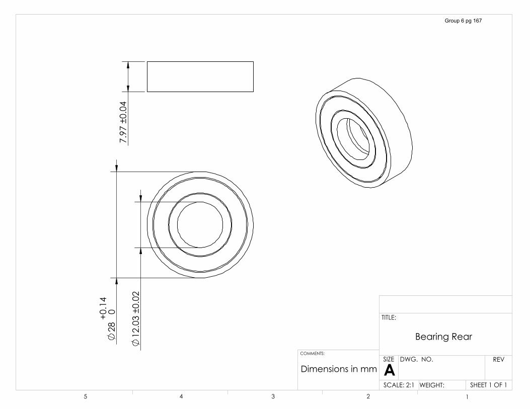
����� ���
���
�
�������������
������������
'LPHQVLRQV�LQ�PP
%HDULQJ�5HDU
6+((7���2)��6&$/(����� :(,*+7��
5(9':*���12�
$6,=(
7,7/(�
&200(176�
� � � � �
Group 6 pg 167
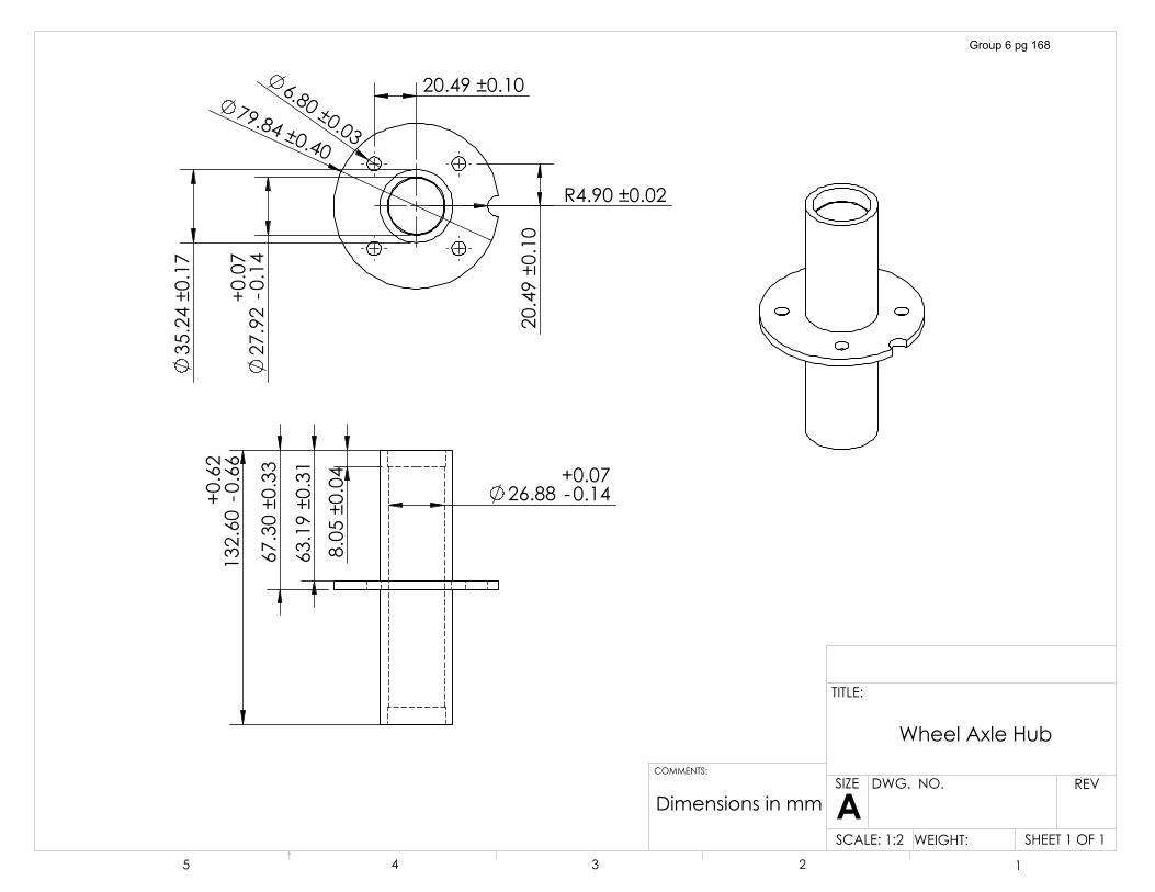
������������
�������������
�������������
��������� ���
�������
� �����������������
�������� ���
�������
�������������
� ������������
������������
�������������
�������������
�5�����������
'LPHQVLRQV�LQ�PP
:KHHO�$[OH�+XE
6+((7���2)��6&$/(����� :(,*+7��
5(9':*���12�
$6,=(
7,7/(�
&200(176�
� � � � �
Group 6 pg 168
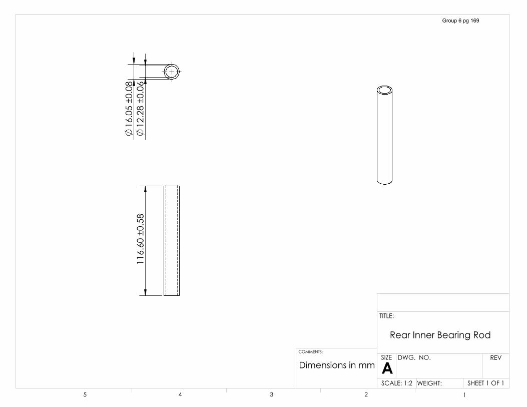
��������������
�������������
�������������
'LPHQVLRQV�LQ�PP
5HDU�,QQHU�%HDULQJ�5RG
6+((7���2)��6&$/(����� :(,*+7��
5(9':*���12�
$6,=(
7,7/(�
� � � � �
&200(176�
Group 6 pg 169
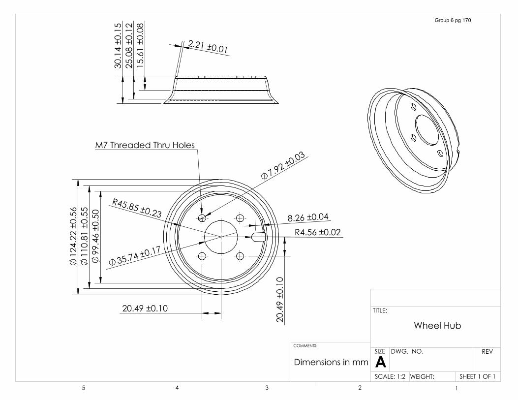
��������������
��������������
�������������
�5������������
� ������������
������������
������������
�5�����������
�������������
�������������
0��7KUHDGHG�7KUX�+ROHV�������������
�������������
�������������
������������
'LPHQVLRQV�LQ�PP
:KHHO�+XE
6+((7���2)��6&$/(����� :(,*+7��
5(9':*���12�
$6,=(
7,7/(�
&200(176�
� � � � �
Group 6 pg 170
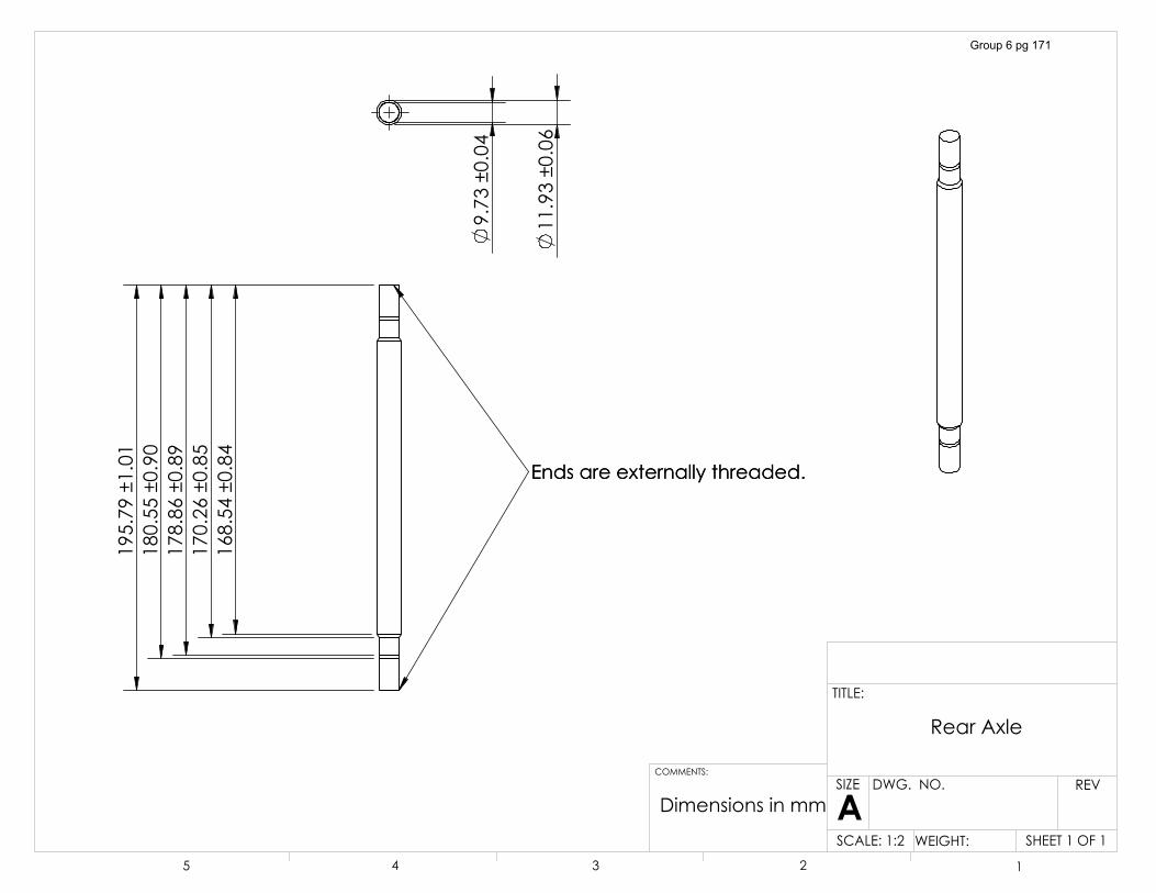
��������������
��������������
��������������
��������������
��������������
(QGV�DUH�H[WHUQDOO\�WKUHDGHG�(QGV�DUH�H[WHUQDOO\�WKUHDGHG�
�������������
������������
'LPHQVLRQV�LQ�PP
5HDU�$[OH
6+((7���2)��6&$/(����� :(,*+7��
5(9':*���12�
$6,=(
7,7/(�
&200(176�
� � � � �
Group 6 pg 171
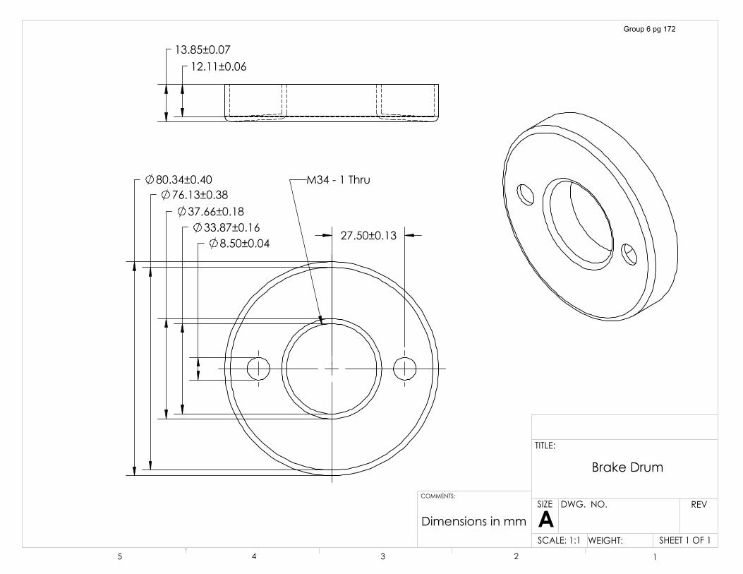
� ������������ �����������
� ������������ �����������
� ����������������������
0�������7KUX
������������������������
'LPHQVLRQV�LQ�PP
%UDNH�'UXP
6+((7���2)��6&$/(����� :(,*+7��
5(9':*���12�
$6,=(
7,7/(�
&200(176�
� � � � �
Group 6 pg 172
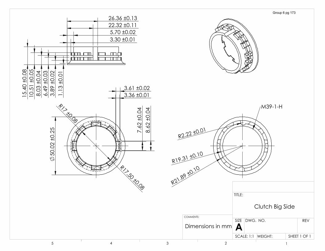
�������������
�5���������
�5������������
������������
������������
��������������������������
����������
������������
������������
������������
�������������
�������������
��������������������������������������������������
�5������������
�5����������
��
�5����������
�
0�����+
'LPHQVLRQV�LQ�PP
&OXWFK�%LJ�6LGH
6+((7���2)��6&$/(����� :(,*+7��
5(9':*���12�
$6,=(
7,7/(�
&200(176�
� � � � �
Group 6 pg 173

������������
'LPHQVLRQV�LQ�PP
&OXWFK�%DOO�%HDULQJ
6+((7���2)��6&$/(������ :(,*+7��
5(9':*���12�
$6,=(
7,7/(�
&200(176�
� � � � �
Group 6 pg 174
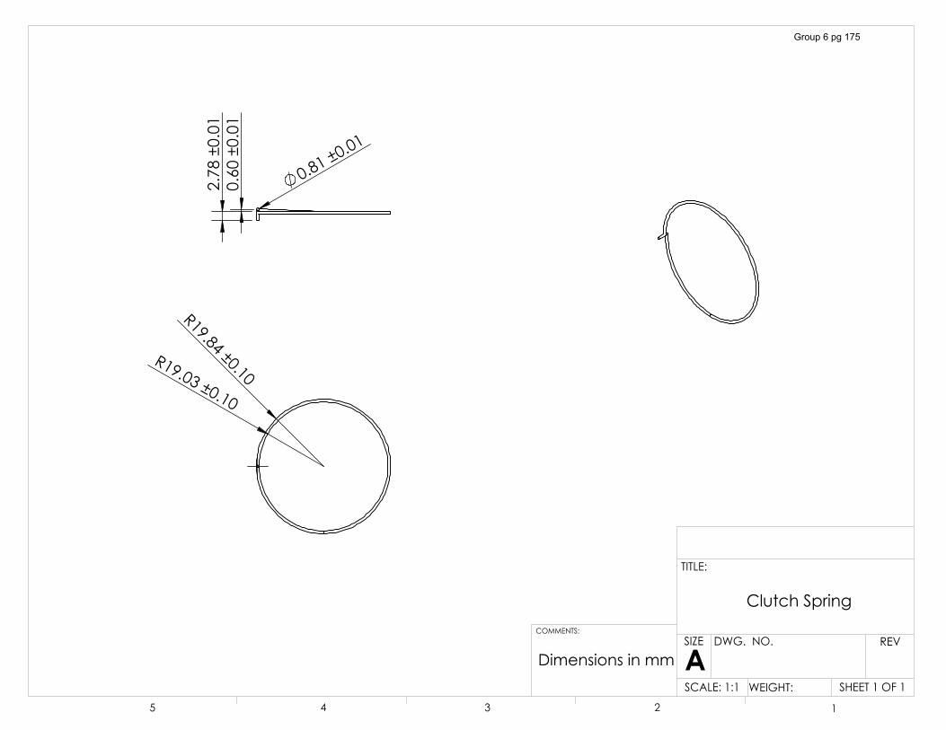
�5�������������5������������
������������
������������
������������
'LPHQVLRQV�LQ�PP
&OXWFK�6SULQJ
6+((7���2)��6&$/(����� :(,*+7��
5(9':*���12�
$6,=(
7,7/(�
&200(176�
� � � � �
Group 6 pg 175
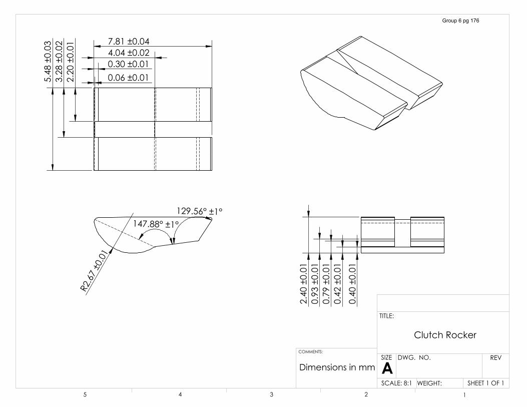
�������������
�5�����������
�������������
������������������������������������������������
������������
������������
������������
������������
������������
������������
������������
������������
'LPHQVLRQV�LQ�PP
&OXWFK�5RFNHU
6+((7���2)��6&$/(����� :(,*+7��
5(9':*���12�
$6,=(
7,7/(�
� � � � �
&200(176�
Group 6 pg 176
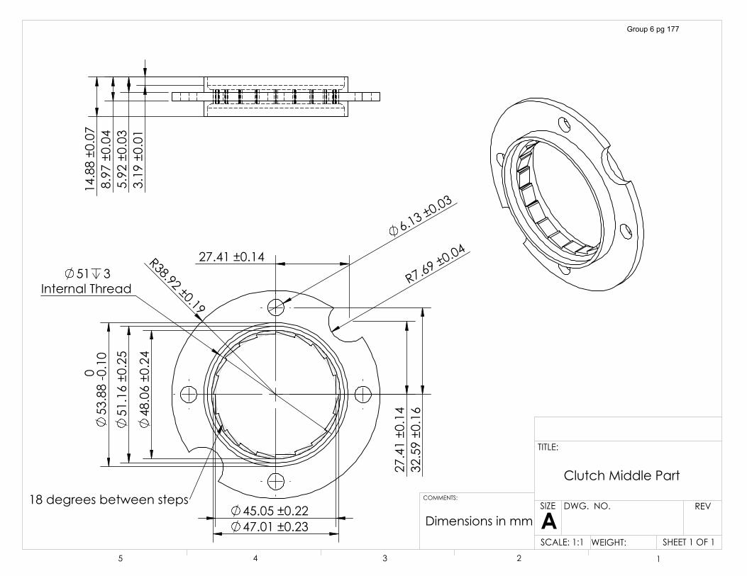
�5������������
�������� �� �����
�������������
�������������
������������
�������������
�5�����������
�������������
��������������� �
,QWHUQDO�7KUHDG
� ������������� ������������
���GHJUHHV�EHWZHHQ�VWHSV
������������
������������
������������
�������������
'LPHQVLRQV�LQ�PP
&OXWFK�0LGGOH�3DUW
6+((7���2)��6&$/(����� :(,*+7��
5(9':*���12�
$6,=(
7,7/(�
&200(176�
� � � � �
Group 6 pg 177
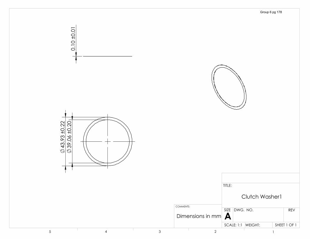
�������������
�������������
������������
'LPHQVLRQV�LQ�PP
&OXWFK�:DVKHU�
6+((7���2)��6&$/(����� :(,*+7��
5(9':*���12�
$6,=(
7,7/(�
&200(176�
� � � � �
Group 6 pg 178
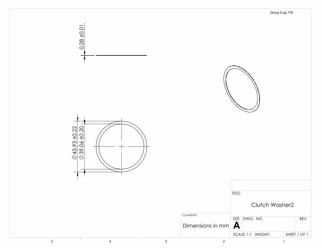
�������������
�������������
������������
'LPHQVLRQV�LQ�PP
&OXWFK�:DVKHU�
6+((7���2)��6&$/(����� :(,*+7��
5(9':*���12�
$6,=(
7,7/(�
&200(176�
� � � � �
Group 6 pg 179
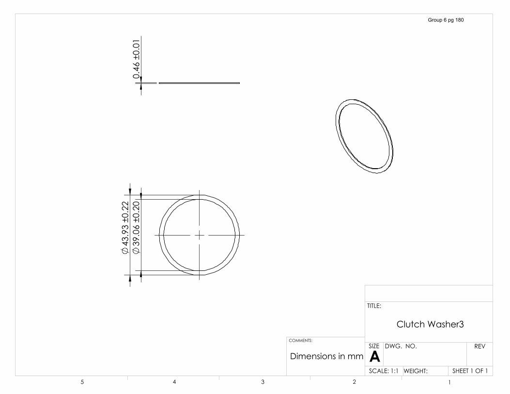
�������������
�������������
������������
'LPHQVLRQV�LQ�PP
&OXWFK�:DVKHU�
6+((7���2)��6&$/(����� :(,*+7��
5(9':*���12�
$6,=(
7,7/(�
&200(176�
� � � � �
Group 6 pg 180
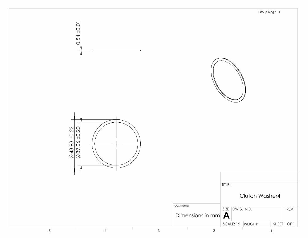
�������������
�������������
������������
'LPHQVLRQV�LQ�PP
&OXWFK�:DVKHU�
6+((7���2)��6&$/(����� :(,*+7��
5(9':*���12�
$6,=(
7,7/(�
&200(176�
� � � � �
Group 6 pg 181
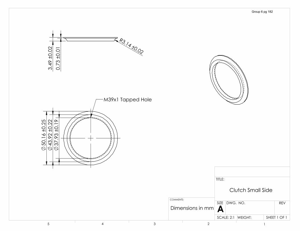
�������������
�������������
�������������
0��[��7DSSHG�+ROH
������������
������������
�5�����������
'LPHQVLRQV�LQ�PP
&OXWFK�6PDOO�6LGH
6+((7���2)��6&$/(����� :(,*+7��
5(9':*���12�
$6,=(
7,7/(�
&200(176�
� � � � �
Group 6 pg 182
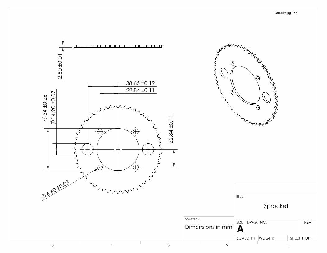
����������
�������������
������������
��������������������������
�������������
������������
'LPHQVLRQV�LQ�PP
6SURFNHW
6+((7���2)��6&$/(����� :(,*+7��
5(9':*���12�
$6,=(
7,7/(�
&200(176�
� � � � �
Group 6 pg 183
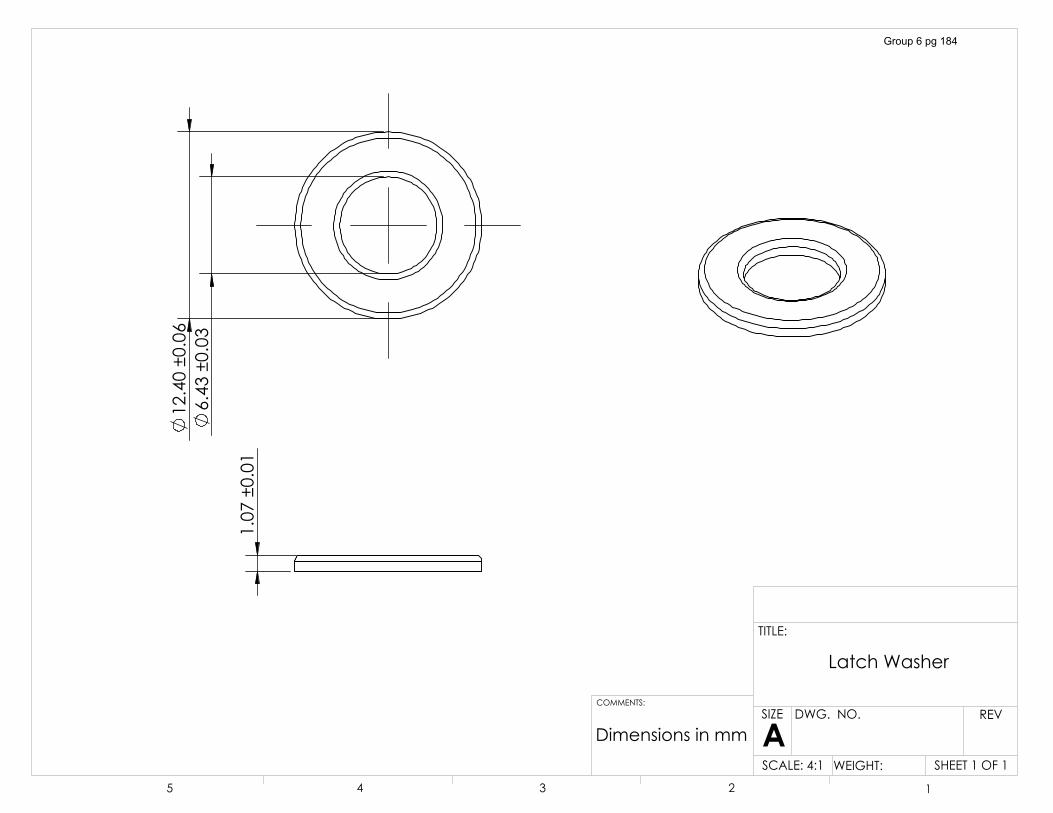
������������
�������������
������������
'LPHQVLRQV�LQ�PP
/DWFK�:DVKHU
6+((7���2)��6&$/(����� :(,*+7��
5(9':*���12�
$6,=(
7,7/(�
&200(176�
� � � � �
Group 6 pg 184
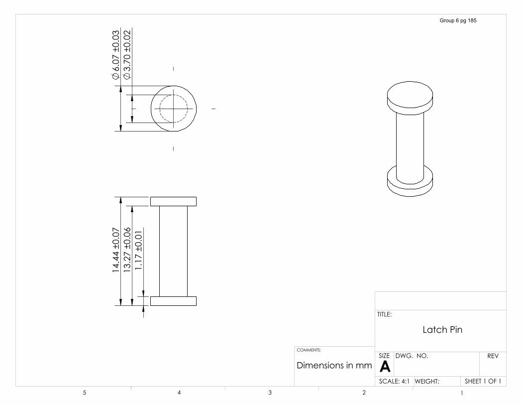
������������
�������������
�������������
������������
������������
'LPHQVLRQV�LQ�PP
/DWFK�3LQ
6+((7���2)��6&$/(����� :(,*+7��
5(9':*���12�
$6,=(
7,7/(�
&200(176�
� � � � �
Group 6 pg 185
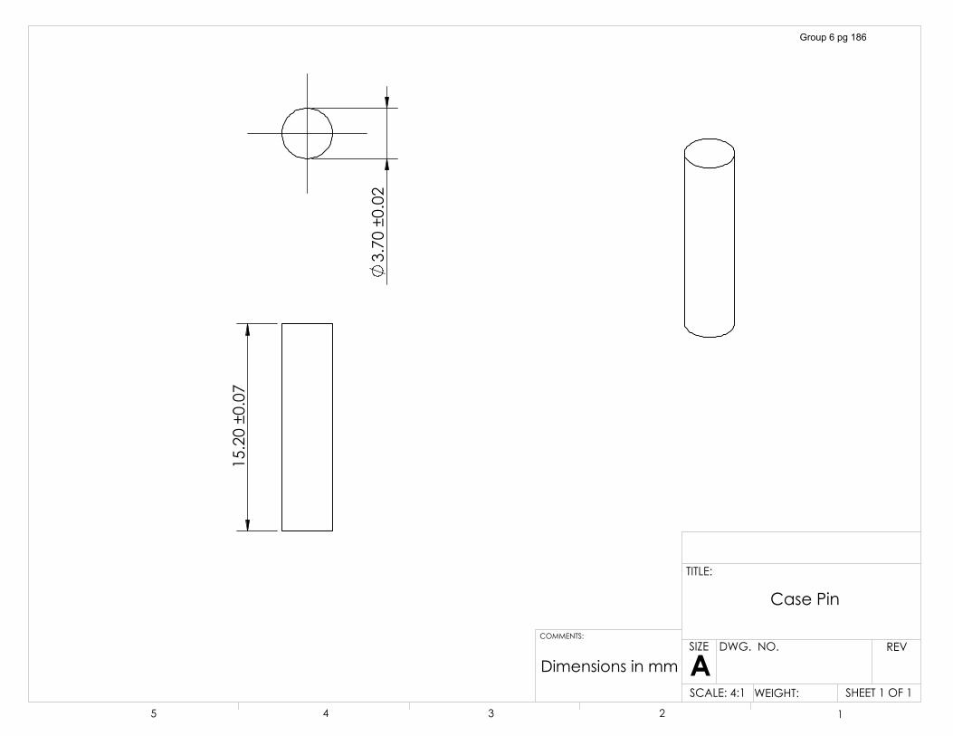
�������������
������������
'LPHQVLRQV�LQ�PP
&DVH�3LQ
6+((7���2)��6&$/(����� :(,*+7��
5(9':*���12�
$6,=(
7,7/(�
&200(176�
� � � � �
Group 6 pg 186
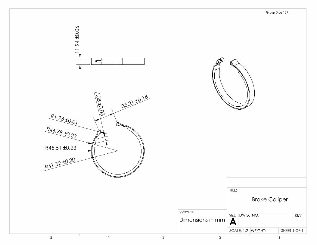
�5������������
�5������������
�5����������
��
�5�����������
������������
���������
����
�������������
'LPHQVLRQV�LQ�PP
%UDNH�&DOLSHU
6+((7���2)��6&$/(����� :(,*+7��
5(9':*���12�
$6,=(
7,7/(�
&200(176�
� � � � �
Group 6 pg 187
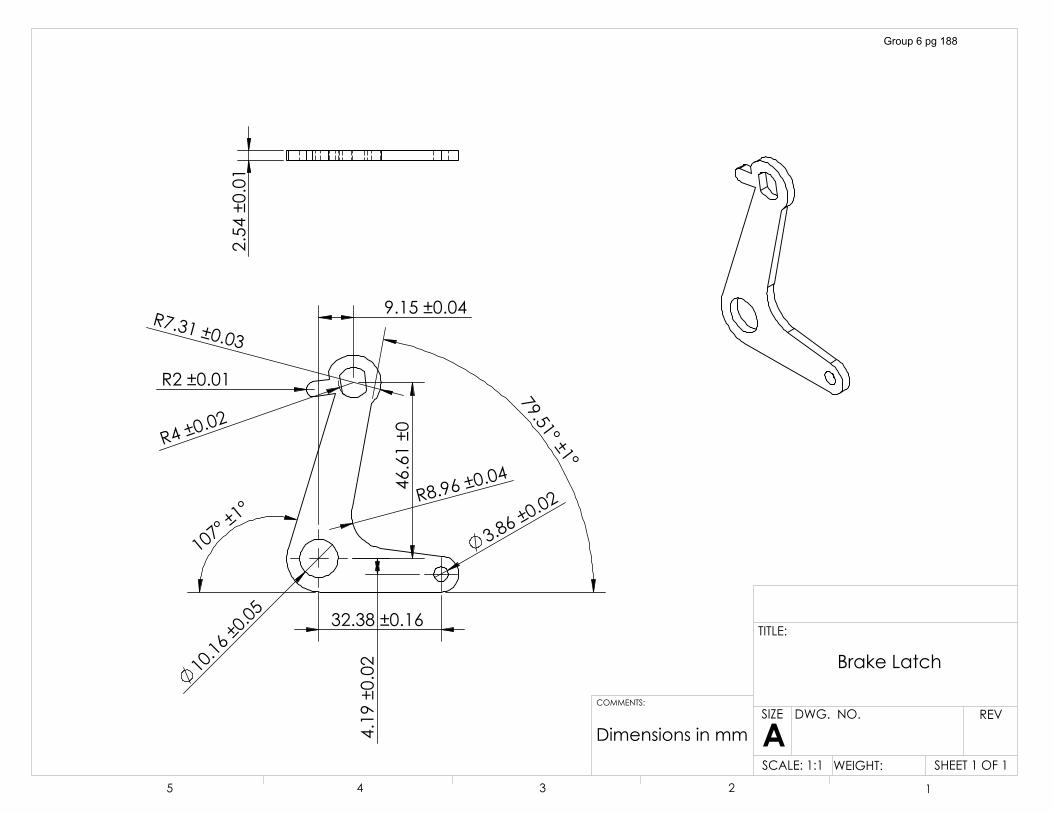
�������������
������������
�5��������
�������������
������������
����������
������������
�5��������
�5����������
�
����������
������������
�5�����������
������������
'LPHQVLRQV�LQ�PP
%UDNH�/DWFK
6+((7���2)��6&$/(����� :(,*+7��
5(9':*���12�
$6,=(
7,7/(�
&200(176�
� � � � �
Group 6 pg 188
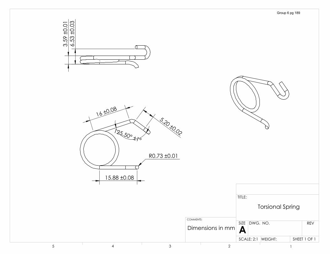
�������������
�5�����������
����������
�������������������������
������������
������������
'LPHQVLRQV�LQ�PP
7RUVLRQDO�6SULQJ
6+((7���2)��6&$/(����� :(,*+7��
5(9':*���12�
$6,=(
7,7/(�
&200(176�
� � � � �
Group 6 pg 189
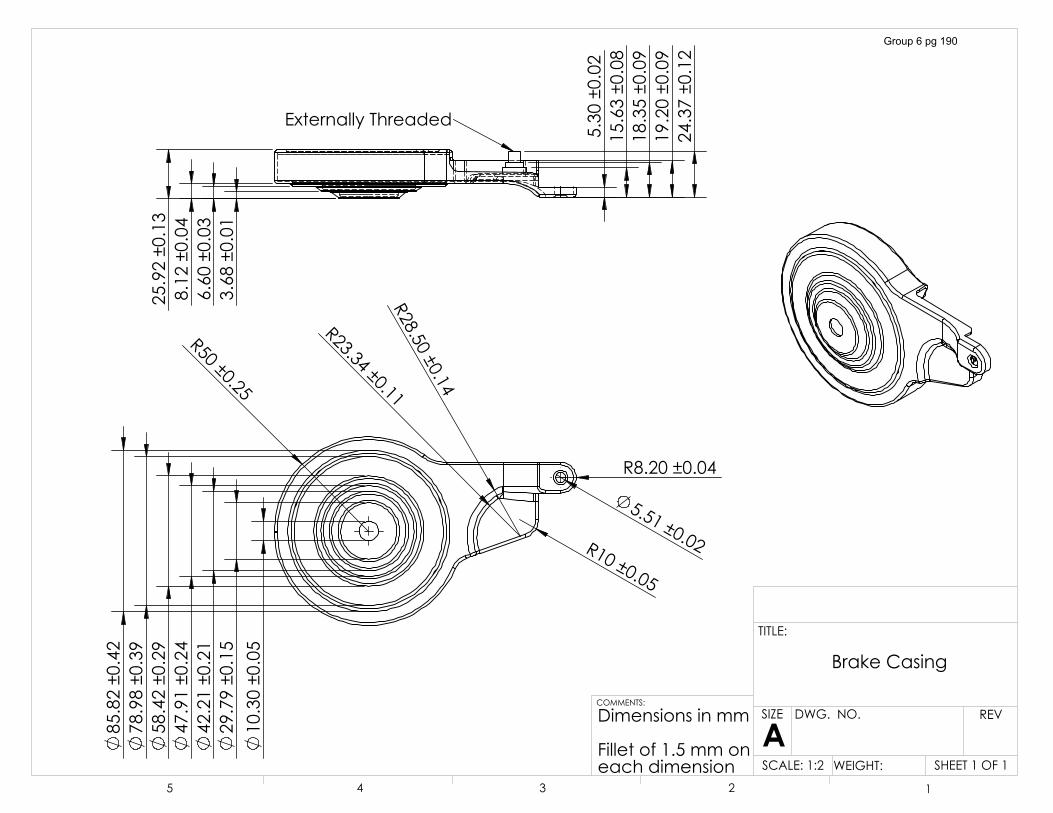
�5���������
�������������
�������������
�������������
�������������
�������������
�������������
�������������
�5������������
�����������
�5������������
�5���������
�5������������
������������
������������
������������
�������������
������������
�������������
�������������
�������������
�������������
'LPHQVLRQV�LQ�PP
)LOOHW�RI�����PP�RQHDFK�GLPHQVLRQ
([WHUQDOO\�7KUHDGHG
%UDNH�&DVLQJ
6+((7���2)��6&$/(����� :(,*+7��
5(9':*���12�
$6,=(
7,7/(�
&200(176�
� � � � �
Group 6 pg 190
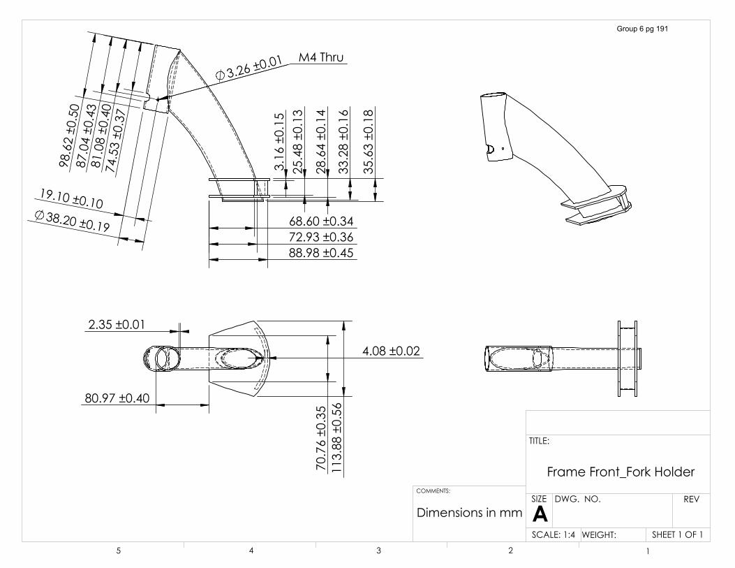
��������������������������������������
��������������������������
�������������
�������������
�������������
� �����������
�������������
�������������� ������������ �������������
��������������������������
������������
�������������
�������������
�������������
�������������
�0��7KUX�
'LPHQVLRQV�LQ�PP
)UDPH�)URQWB)RUN�+ROGHU
6+((7���2)��6&$/(����� :(,*+7��
5(9':*���12�
$6,=(
7,7/(�
&200(176�
� � � � �
Group 6 pg 191
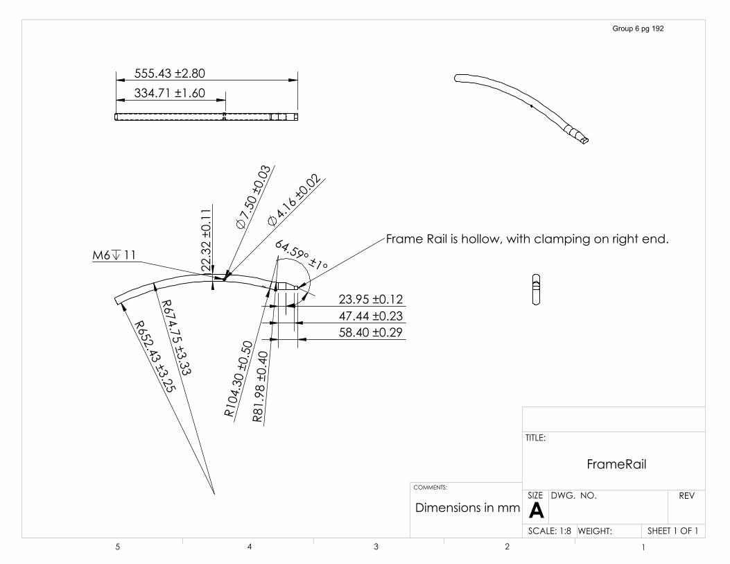
�5�������������
�5�������������
�5�������������
�5������������
���������������������������������������
�������������
������������
������������
������������
0� ��)UDPH�5DLO�LV�KROORZ��ZLWK�FODPSLQJ�RQ�ULJKW�HQG�
����������������������������
'LPHQVLRQV�LQ�PP
)UDPH5DLO
6+((7���2)��6&$/(����� :(,*+7��
5(9':*���12�
$6,=(
7,7/(�
&200(176�
� � � � �
Group 6 pg 192
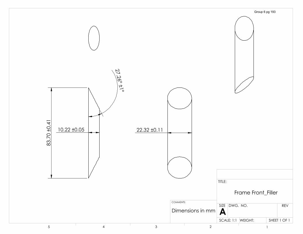
�������������
�������������
������������
�������������
'LPHQVLRQV�LQ�PP
)UDPH�)URQWB)LOOHU
6+((7���2)��6&$/(����� :(,*+7��
5(9':*���12�
$6,=(
7,7/(�
&200(176�
� � � � �
Group 6 pg 193
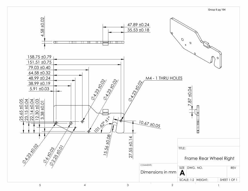
������������
���������
������������
������������
������������
��������������
������������������������������������������������������������������������������
�������������
�������������
�������������
������������
�������������
�������������
�������������
�������������
�������������
������������ 0������7+58�+2/(6
������������
��������������������������
������������
'LPHQVLRQV�LQ�PP
)UDPH�5HDU�:KHHO�5LJKW
6+((7���2)��6&$/(����� :(,*+7��
5(9':*���12�
$6,=(
7,7/(�
&200(176�
� � � � �
Group 6 pg 194
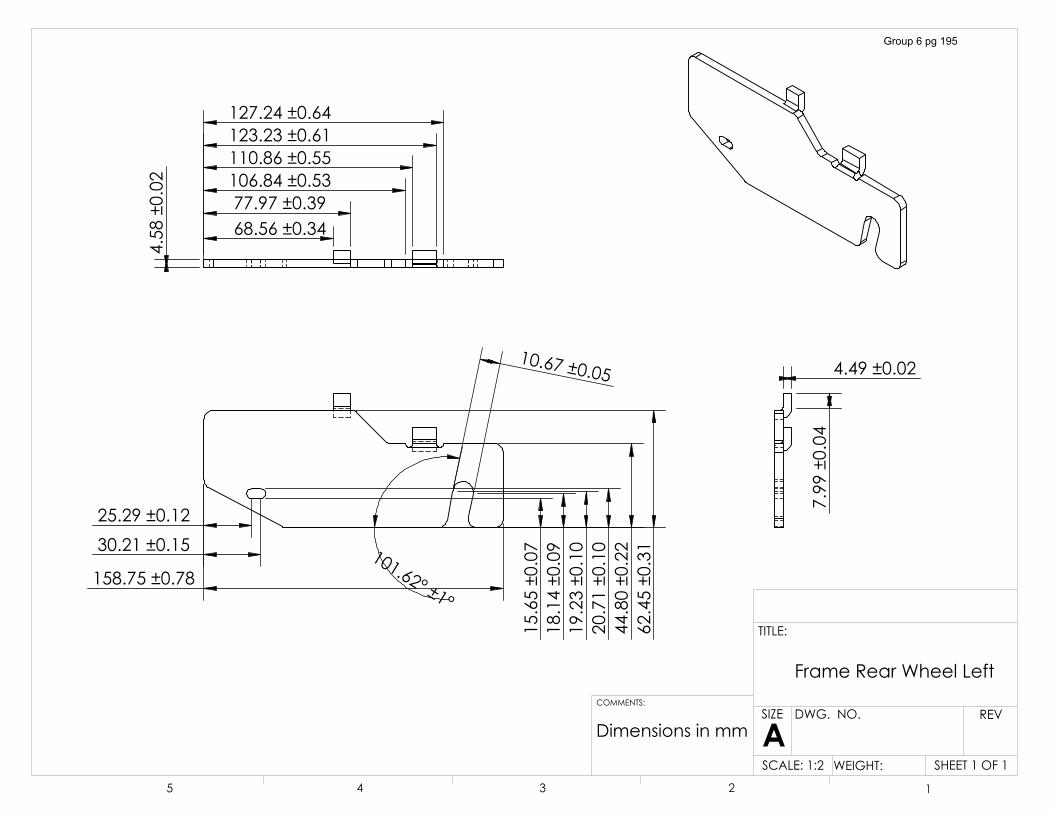
��������������������������
��������������
�������������
�������������
�������������
�������������
�������������
�������������
�������������
�������������
��������������������������
����������������������������
��������������
��������������
������������
������������
������������
'LPHQVLRQV�LQ�PP
)UDPH�5HDU�:KHHO�/HIW
6+((7���2)��6&$/(����� :(,*+7��
5(9':*���12�
$6,=(
7,7/(�
&200(176�
� � � � �
Group 6 pg 195
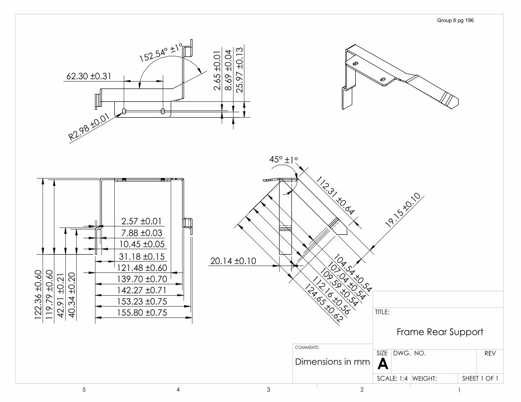
��������������������������������������������������������������������������������������������������������������������������
�����������
�������������
��������������
��������������
���������
��������������
��������������
��������������
��������������
��������������
��������������
�������������
�������������
������������
�5�����������
�������������
������������
�������������
�����������
��
'LPHQVLRQV�LQ�PP
)UDPH�5HDU�6XSSRUW
6+((7���2)��6&$/(����� :(,*+7��
5(9':*���12�
$6,=(
7,7/(�
&200(176�
� � � � �
Group 6 pg 196
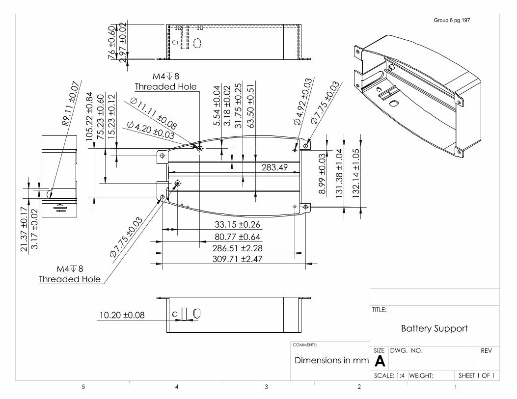
�������������
�������������
��������������
������������
������������� �
�����������
������������
������������
������������
��������������
��������������
������������������������������������������������������
� �����������
��������
������������
�������������
�������������
0� �7KUHDGHG�+ROH
0� �7KUHDGHG�+ROH
������������
����������
�������������
�������������
�5�����������
������������
'LPHQVLRQV�LQ�PP
%DWWHU\�6XSSRUW
6+((7���2)��6&$/(����� :(,*+7��
5(9':*���12�
$6,=(
7,7/(�
&200(176�
� � � � �
Group 6 pg 197
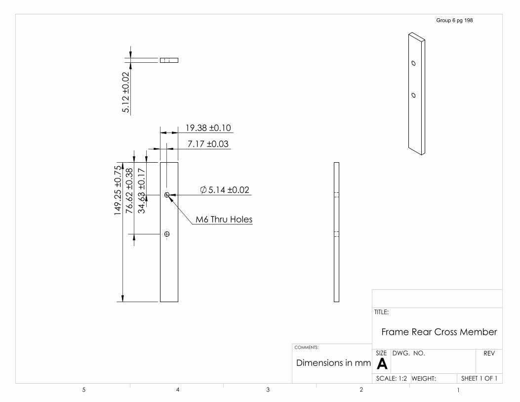
��������������
� �����������
�������������
�������������
������������
�������������
0��7KUX�+ROHV
������������
'LPHQVLRQV�LQ�PP
)UDPH�5HDU�&URVV�0HPEHU
6+((7���2)��6&$/(����� :(,*+7��
5(9':*���12�
$6,=(
7,7/(�
&200(176�
� � � � �
Group 6 pg 198
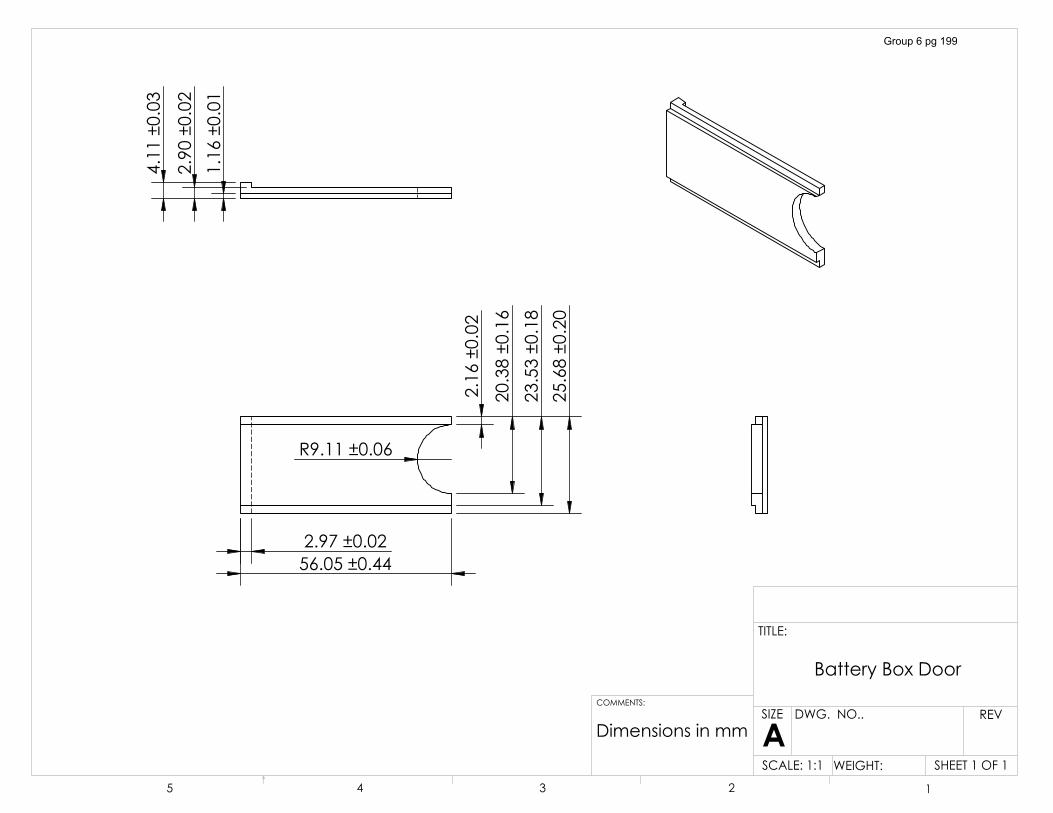
������������
�������������
�������������
�5�����������
�������������
�������������������������
������������
������������
������������
'LPHQVLRQV�LQ�PP
%DWWHU\�%R[�'RRU
6+((7���2)��6&$/(����� :(,*+7��
5(9':*���12��
$6,=(
7,7/(�
&200(176�
� � � � �
Group 6 pg 199
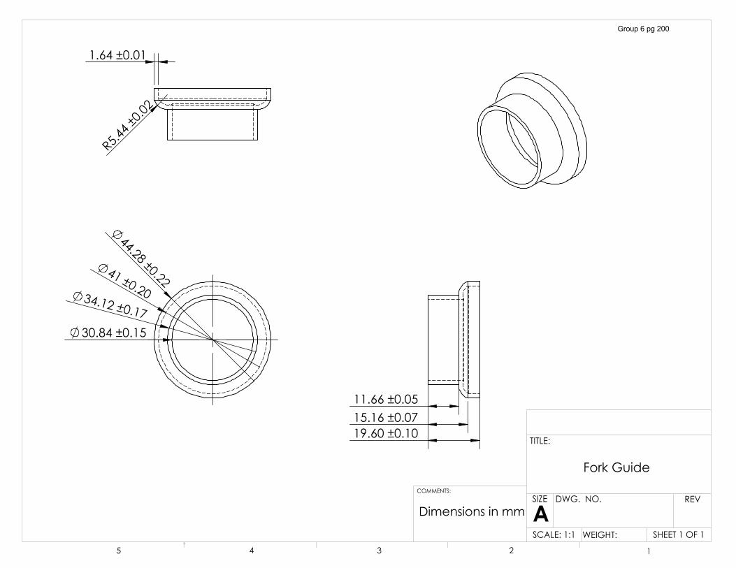
�������������
����������� ������������
� ������������
�5�����������
������������
���������������������������������������
'LPHQVLRQV�LQ�PP
)RUN�*XLGH
6+((7���2)��6&$/(����� :(,*+7��
5(9':*���12�
$6,=(
7,7/(�
&200(176�
� � � � �
Group 6 pg 200
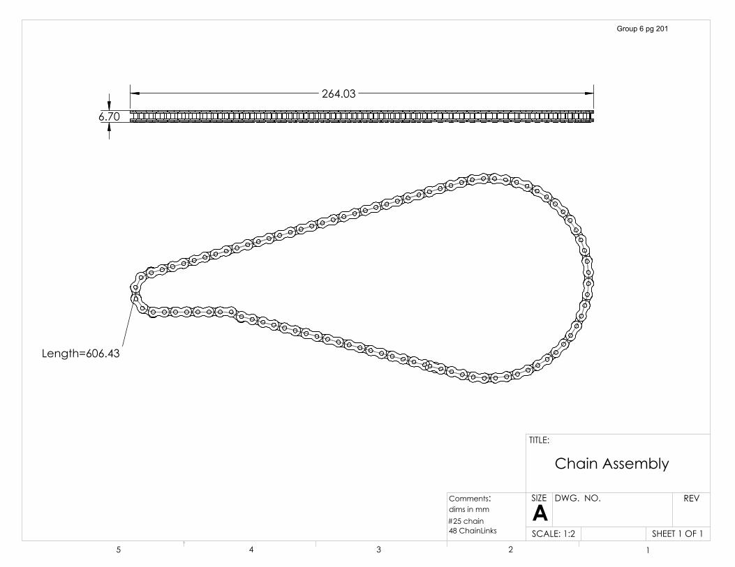
�/HQJWK �������
������
��������
6+((7���2)��6&$/(�����
5(9':*���12�
$6,=(
7,7/(�
� � � � �
&KDLQ�$VVHPEO\
&RPPHQWV�
����FKDLQ���&KDLQ/LQNV
GLPV�LQ�PP
Group 6 pg 201
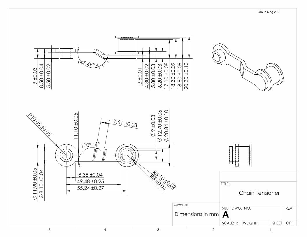
�5������������
�������������
������������
��������������������������������������
�������������
������������
����������
�5��������
�������������
�5�����������
���������
�������������
������������
������������
���������
���������
������������
������������
������������
�������������
�������������
�������������
��������������������������
'LPHQVLRQV�LQ�PP
&KDLQ�7HQVLRQHU
6+((7���2)��6&$/(����� :(,*+7��
5(9':*���12�
$6,=(
7,7/(�
&200(176�
� � � � �
Group 6 pg 202
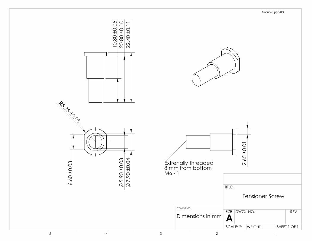
�5�����������
������������
������������
������������
�������������
�������������
�������������
������������
([WUHQDOO\�WKUHDGHG��PP�IURP�ERWWRP0�����
'LPHQVLRQV�LQ�PP
7HQVLRQHU�6FUHZ
6+((7���2)��6&$/(����� :(,*+7��
5(9':*���12�
$6,=(
7,7/(�
&200(176�
� � � � �
Group 6 pg 203
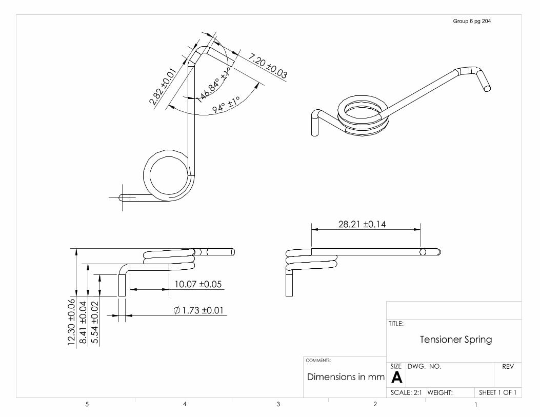
������������
������������
�������������
�������������
� �����������
�������������
��������
�������������
������������
�������������
'LPHQVLRQV�LQ�PP
7HQVLRQHU�6SULQJ
6+((7���2)��6&$/(����� :(,*+7��
5(9':*���12�
$6,=(
7,7/(�
&200(176�
� � � � �
Group 6 pg 204
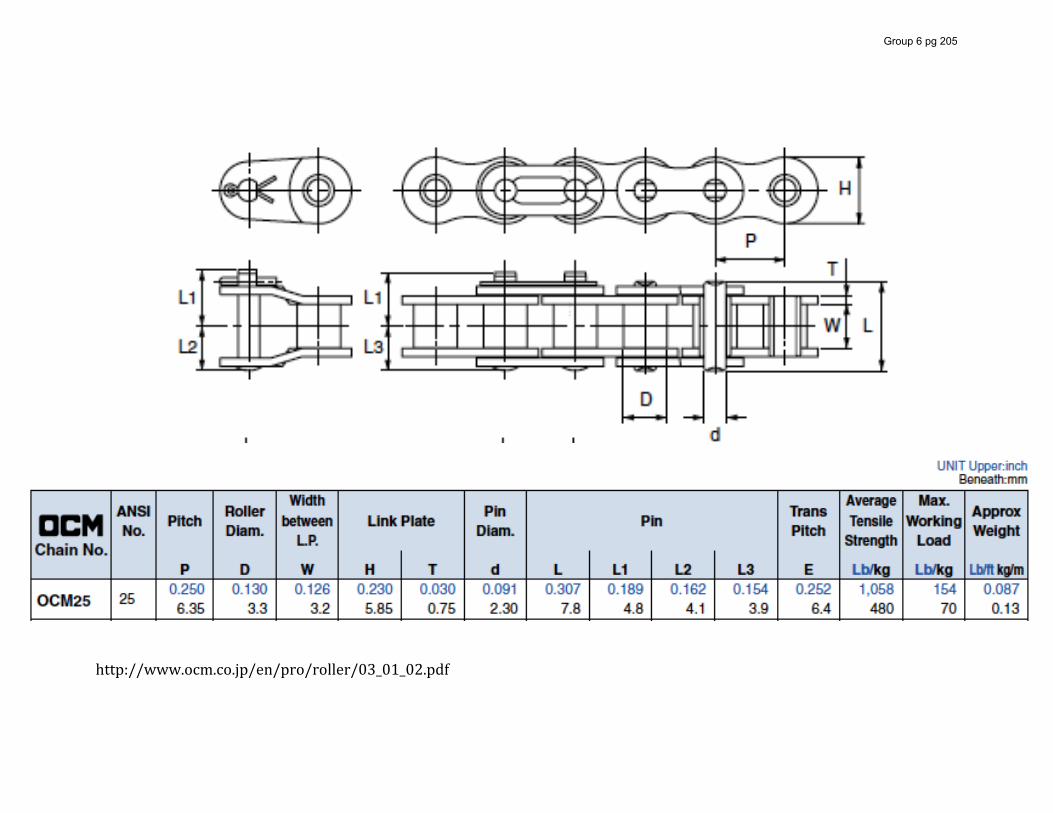
!!http://www.ocm.co.jp/en/pro/roller/03_01_02.pdf!
Group 6 pg 205
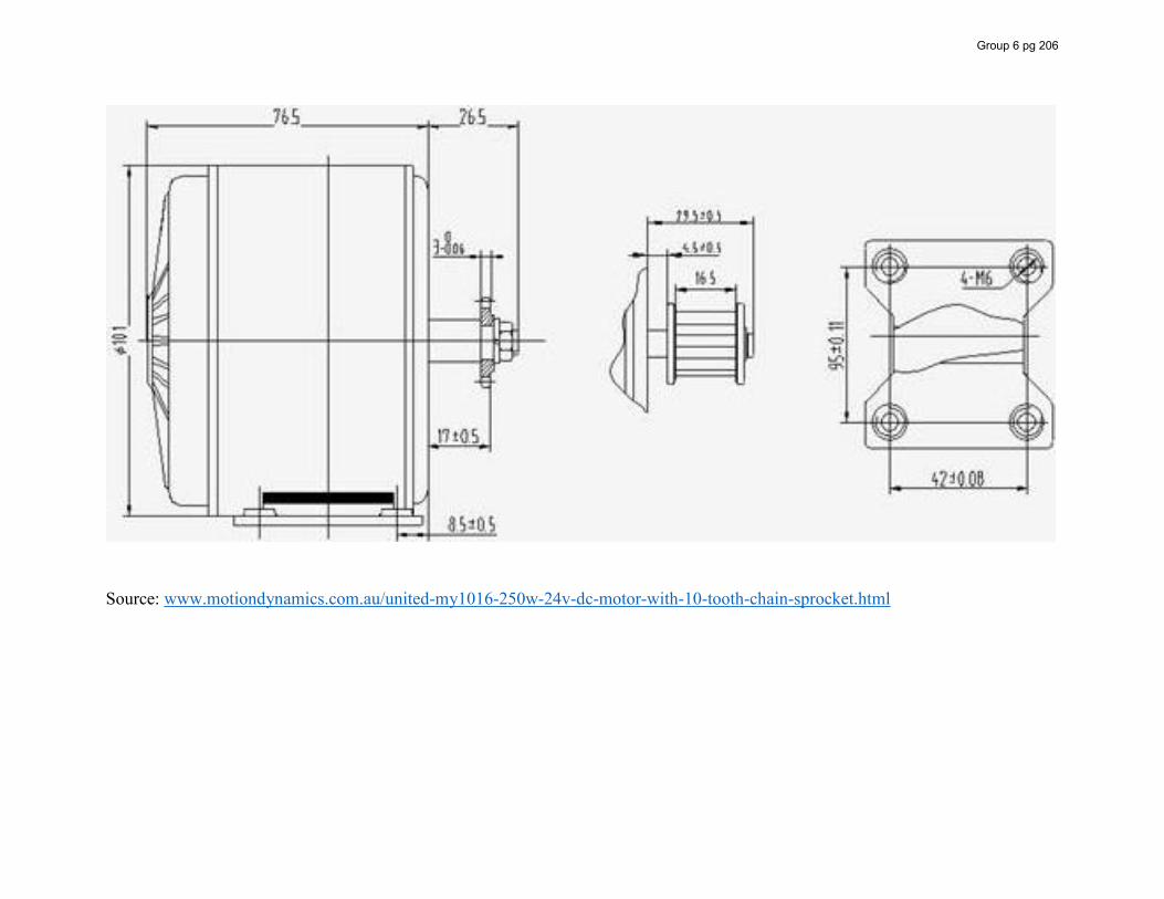
Source: www.motiondynamics.com.au/united-my1016-250w-24v-dc-motor-with-10-tooth-chain-sprocket.html
Group 6 pg 206

Appendix C:
Reference Charts
Group 6 pg 207
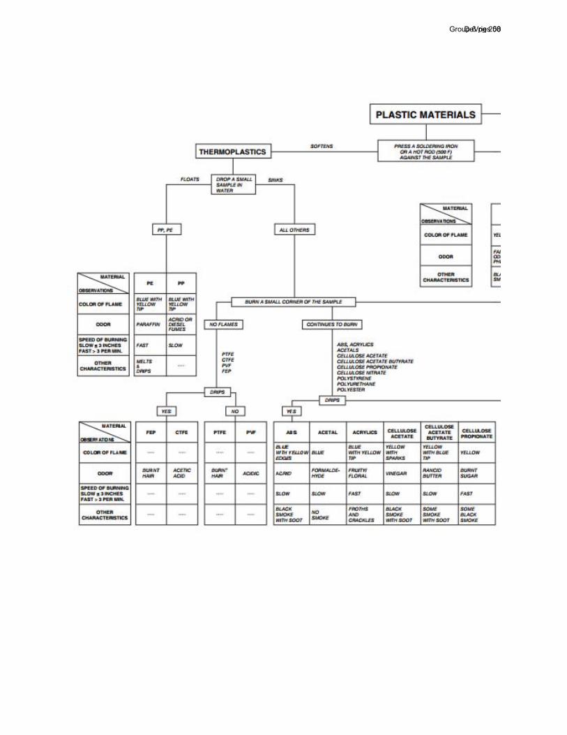
DeVries 50Group 6 pg 208
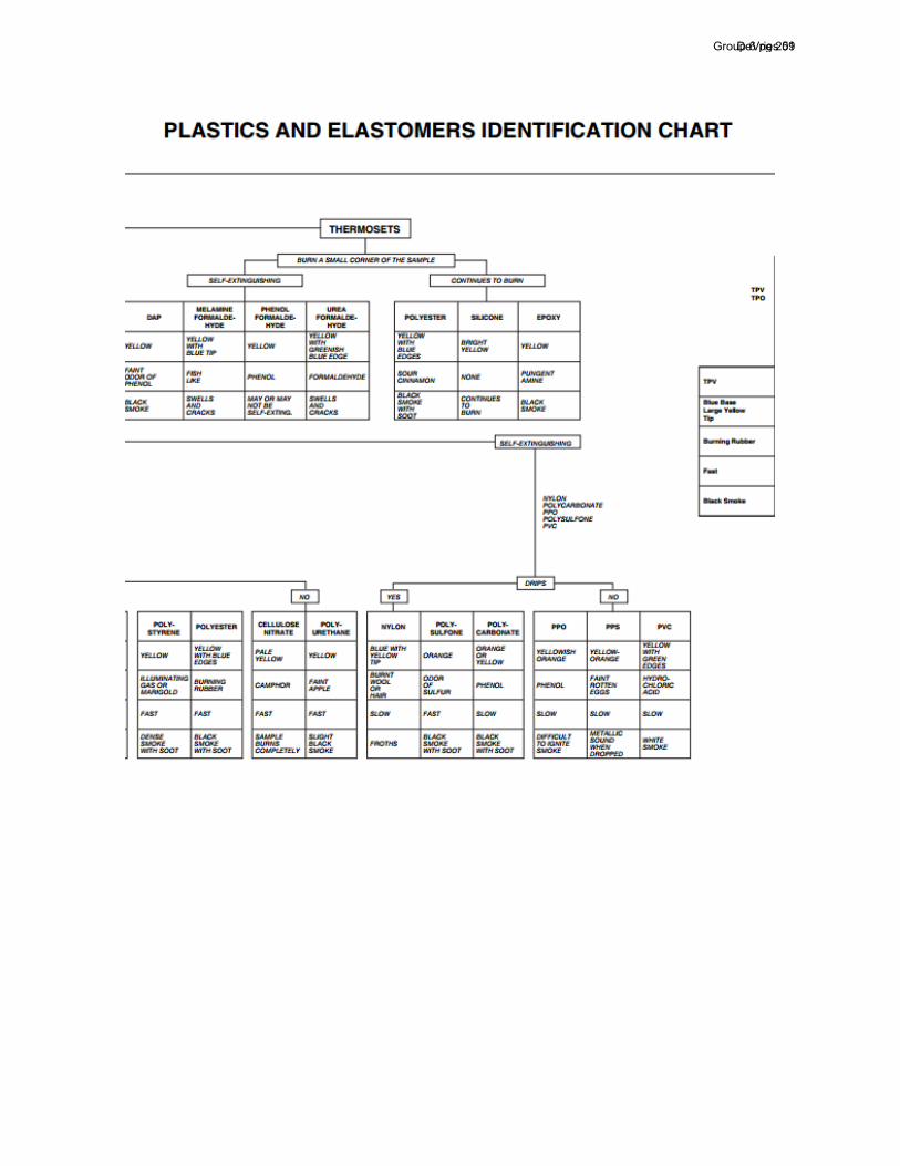
DeVries 51Group 6 pg 209
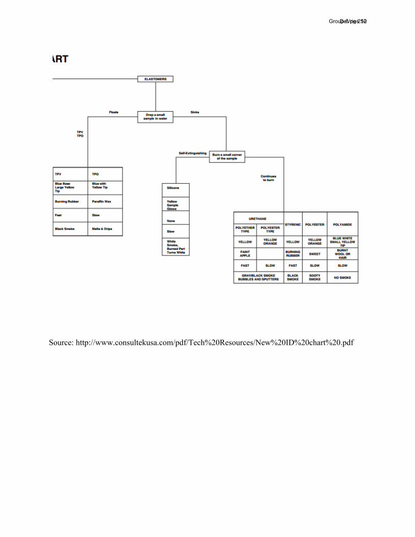
Source: http://www.consultekusa.com/pdf/Tech%20Resources/New%20ID%20chart%20.pdf
DeVries 52Group 6 pg 210
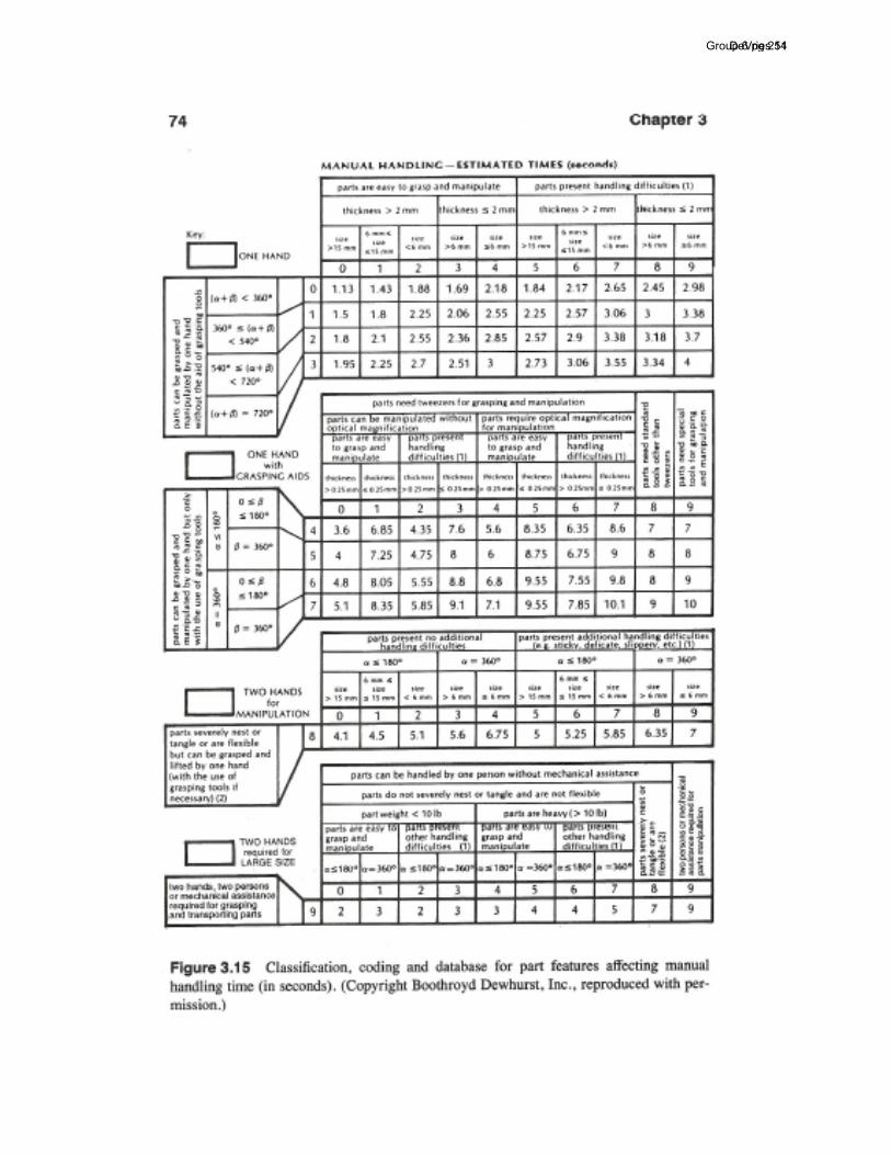
DeVries 54Group 6 pg 211
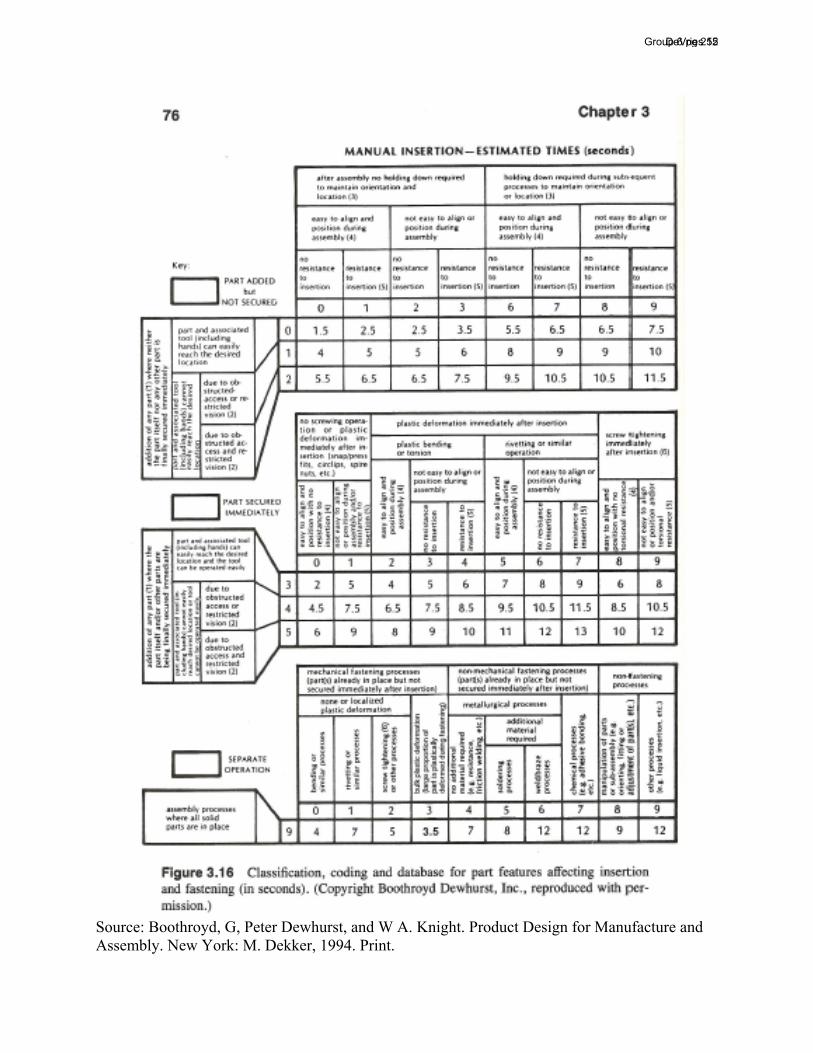
Source: Boothroyd, G, Peter Dewhurst, and W A. Knight. Product Design for Manufacture and Assembly. New York: M. Dekker, 1994. Print.
DeVries 55Group 6 pg 212