graphic communications - web.itu.edu.tr
TRANSCRIPT
ipbuker_graph07İİTTÜÜ--SUNY SUNY 20042004--2005 2005 FallFall
Graphic Graphic CommunicationsCommunications
Lecture 8: Projections
Assoc. Prof.Dr. Cengizhan Assoc. Prof.Dr. Cengizhan İİpbpbüükerker
ipbuker_graph06
ipbuker_graph07
Projections
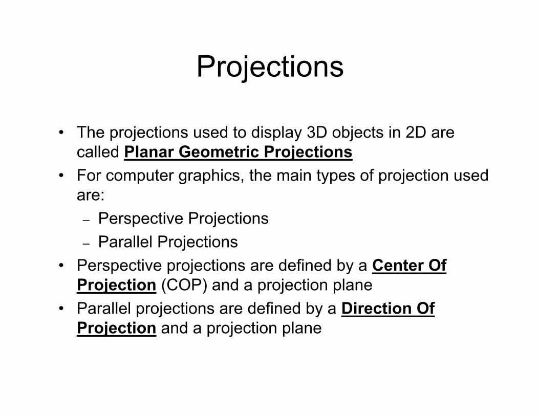
• The projections used to display 3D objects in 2D are called Planar Geometric Projections
• For computer graphics, the main types of projection used are:– Perspective Projections– Parallel Projections
• Perspective projections are defined by a Center Of Projection (COP) and a projection plane
• Parallel projections are defined by a Direction Of Projection and a projection plane
ipbuker_graph07
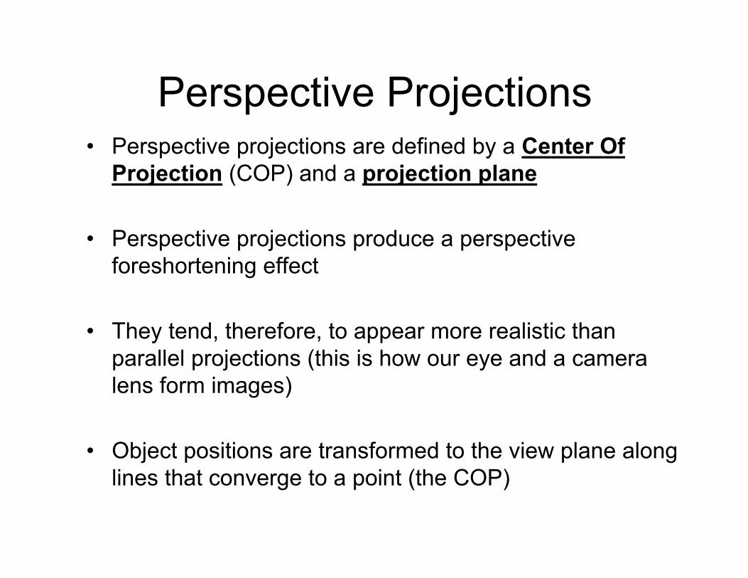
Perspective Projections• Perspective projections are defined by a Center Of
Projection (COP) and a projection plane
• Perspective projections produce a perspective foreshortening effect
• They tend, therefore, to appear more realistic thanparallel projections (this is how our eye and a camera lens form images)
• Object positions are transformed to the view plane along lines that converge to a point (the COP)
ipbuker_graph07
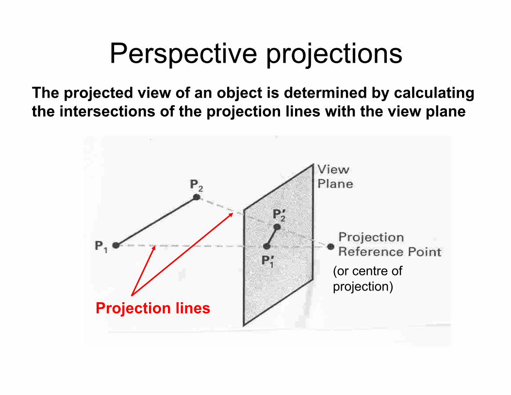
Perspective projections
Projection lines
(or centre of projection)
The projected view of an object is determined by calculating the intersections of the projection lines with the view plane
ipbuker_graph07
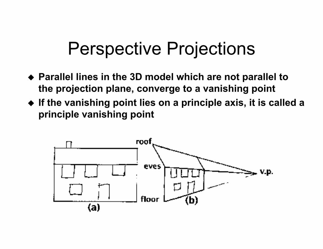
Perspective ProjectionsParallel lines in the 3D model which are not parallel to the projection plane, converge to a vanishing pointIf the vanishing point lies on a principle axis, it is called a principle vanishing point
ipbuker_graph07
Perspective Projections - Cont.• The number of principal vanishing points is
determined by the number of principal axes cut by the projection plane.
• If the plane only cuts the z axis (most common), there is only 1 vanishing point.
• 2-points sometimes used in architecture and engineering. 3-points seldom used …add little extra realism
ipbuker_graph07
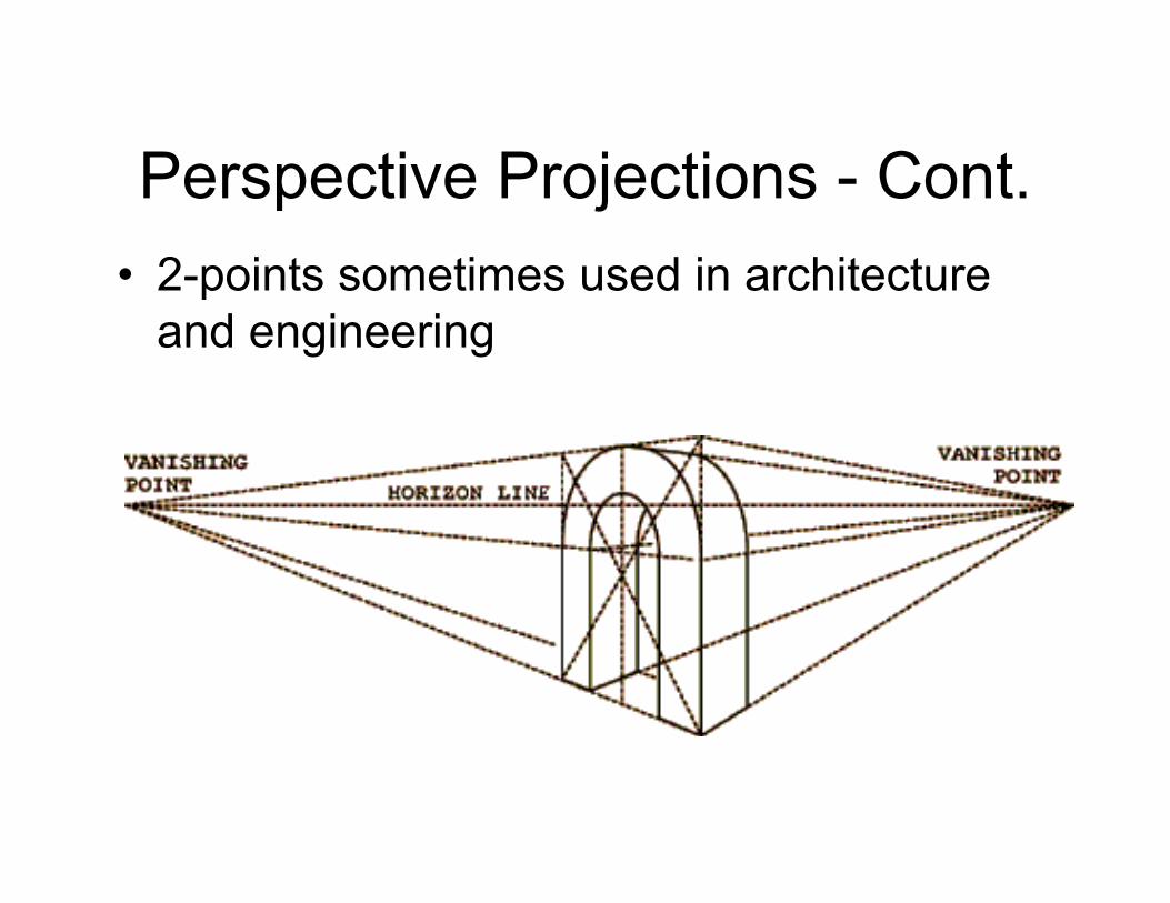
Perspective Projections - Cont.• 2-points sometimes used in architecture
and engineering
ipbuker_graph07
Perspective projectionsPerspective projections
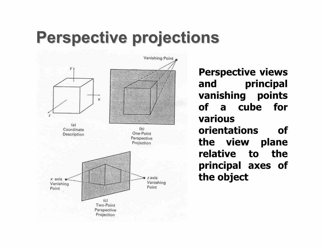
Perspective views and principal vanishing points of a cube for various orientations of the view plane relative to the principal axes of the object
ipbuker_graph07
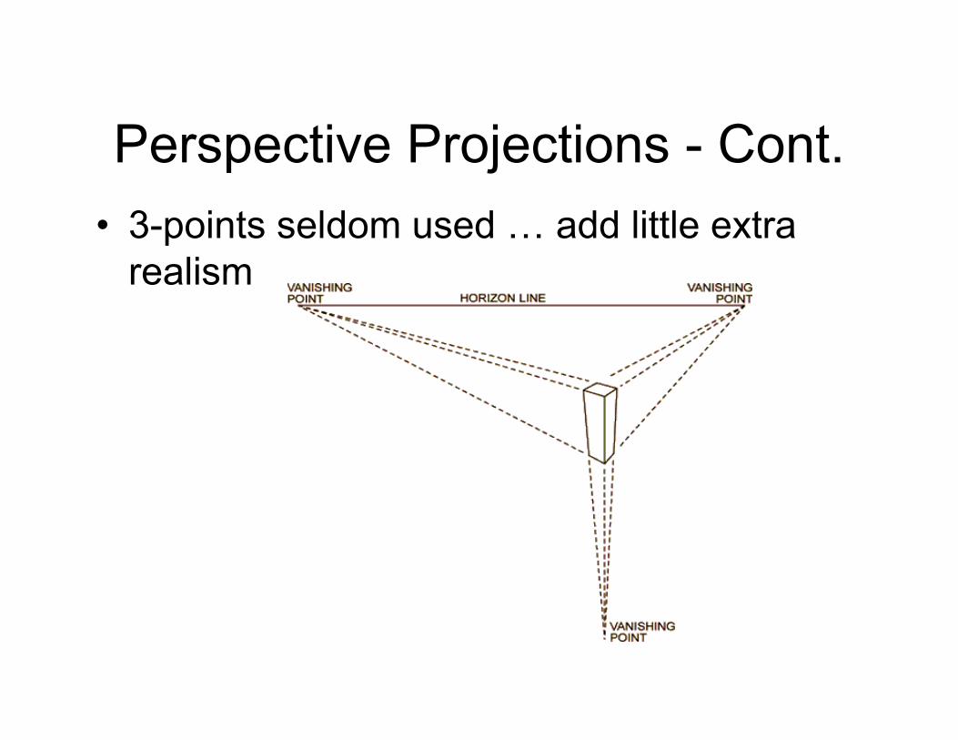
Perspective Projections - Cont.• 3-points seldom used … add little extra
realism
ipbuker_graph07
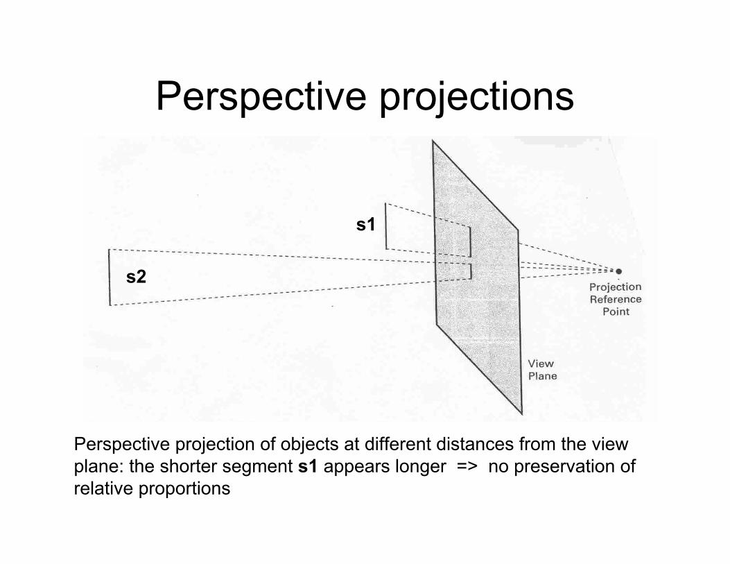
Perspective projections
Perspective projection of objects at different distances from the view plane: the shorter segment s1 appears longer => no preservation of relative proportions
s1
s2
ipbuker_graph07
Parallel Projections
• Parallel projections are defined by a Direction Of Projection (DOP) and a projection plane
• DOP also called projection vector
• Coordinate positions are transformed to the view plane along parallel lines
• Important property: they preserve relative proportions of objects
• Less realistic effect
ipbuker_graph07
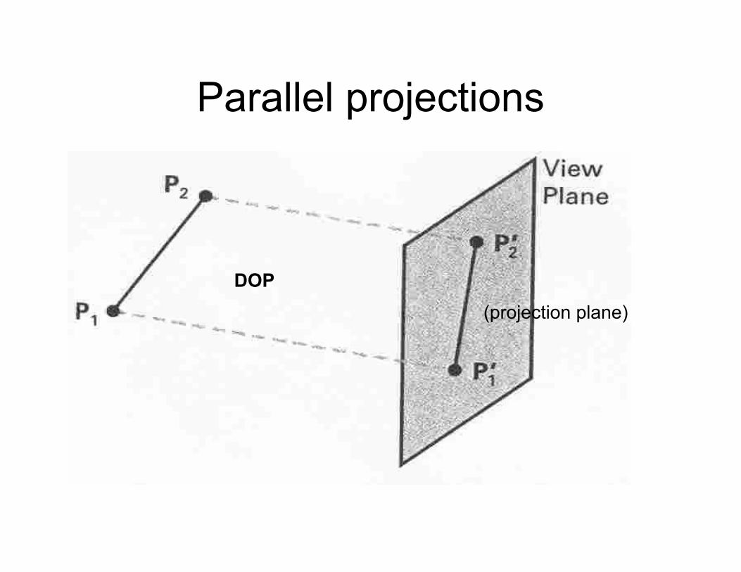
Parallel projections
DOP(projection plane)
ipbuker_graph07
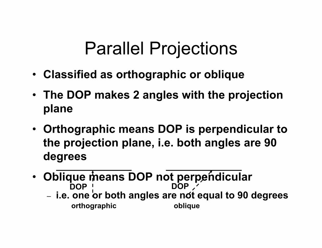
Parallel Projections• Classified as orthographic or oblique
• The DOP makes 2 angles with the projection plane
• Orthographic means DOP is perpendicular to the projection plane, i.e. both angles are 90 degrees
• Oblique means DOP not perpendicular– i.e. one or both angles are not equal to 90 degrees
DOP DOP
orthographic oblique
ipbuker_graph07
Parallel projections
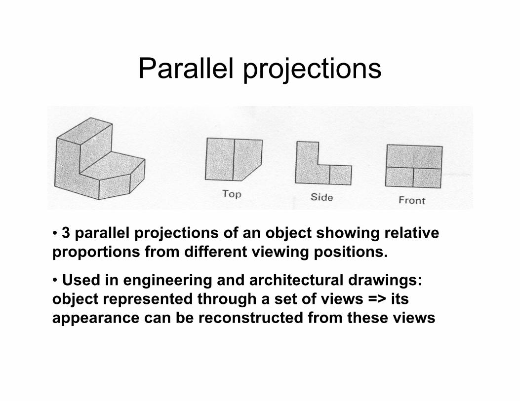
• 3 parallel projections of an object showing relative proportions from different viewing positions.
• Used in engineering and architectural drawings: object represented through a set of views => its appearance can be reconstructed from these views
ipbuker_graph07
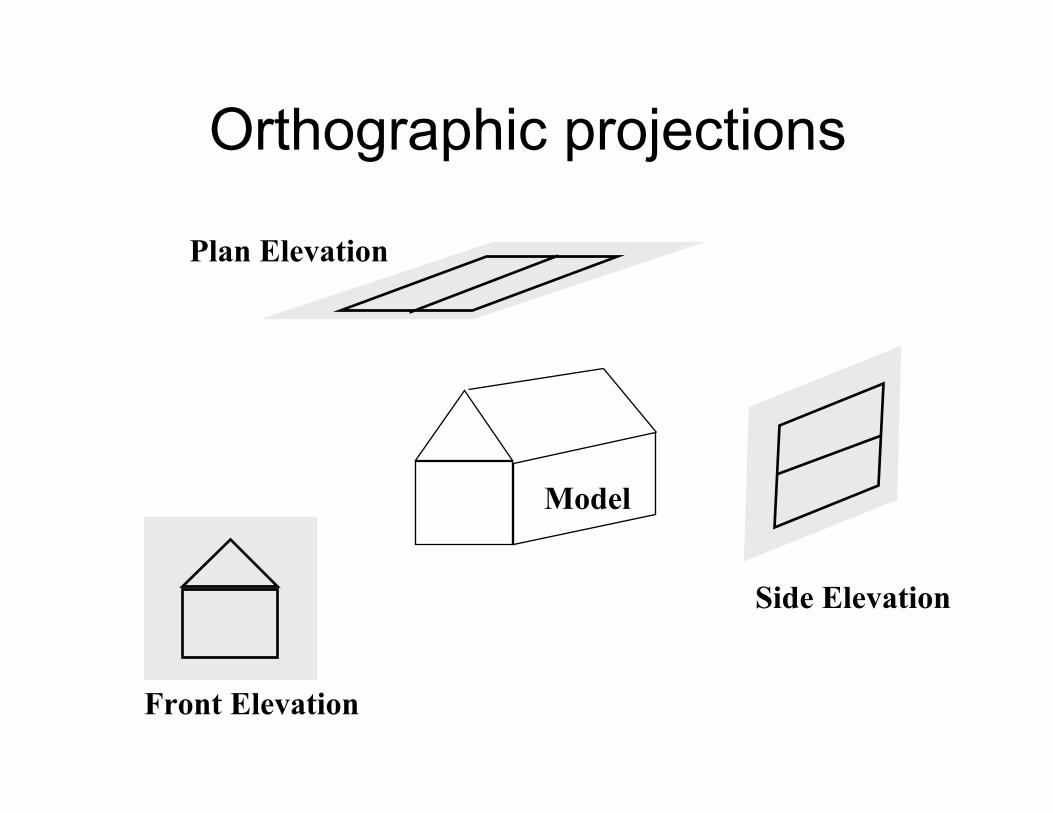
Orthographic projections
Model
Front Elevation
Side Elevation
Plan Elevation
ipbuker_graph07
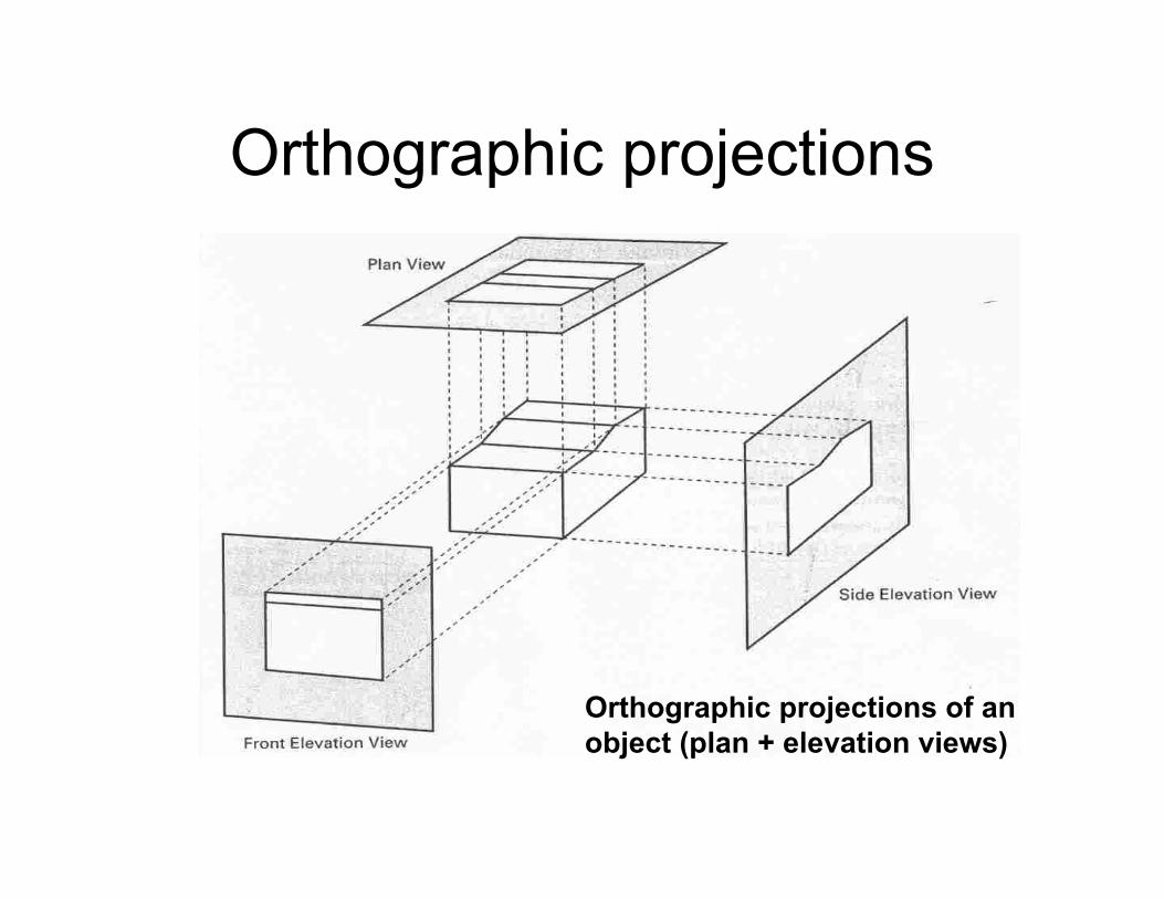
Orthographic projections
Orthographic projections of an object (plan + elevation views)
ipbuker_graph07
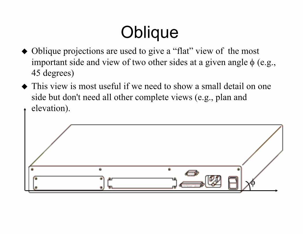
ObliqueOblique projections are used to give a “flat” view of the most important side and view of two other sides at a given angle φ (e.g., 45 degrees)This view is most useful if we need to show a small detail on one side but don't need all other complete views (e.g., plan and elevation).
φ
ipbuker_graph07
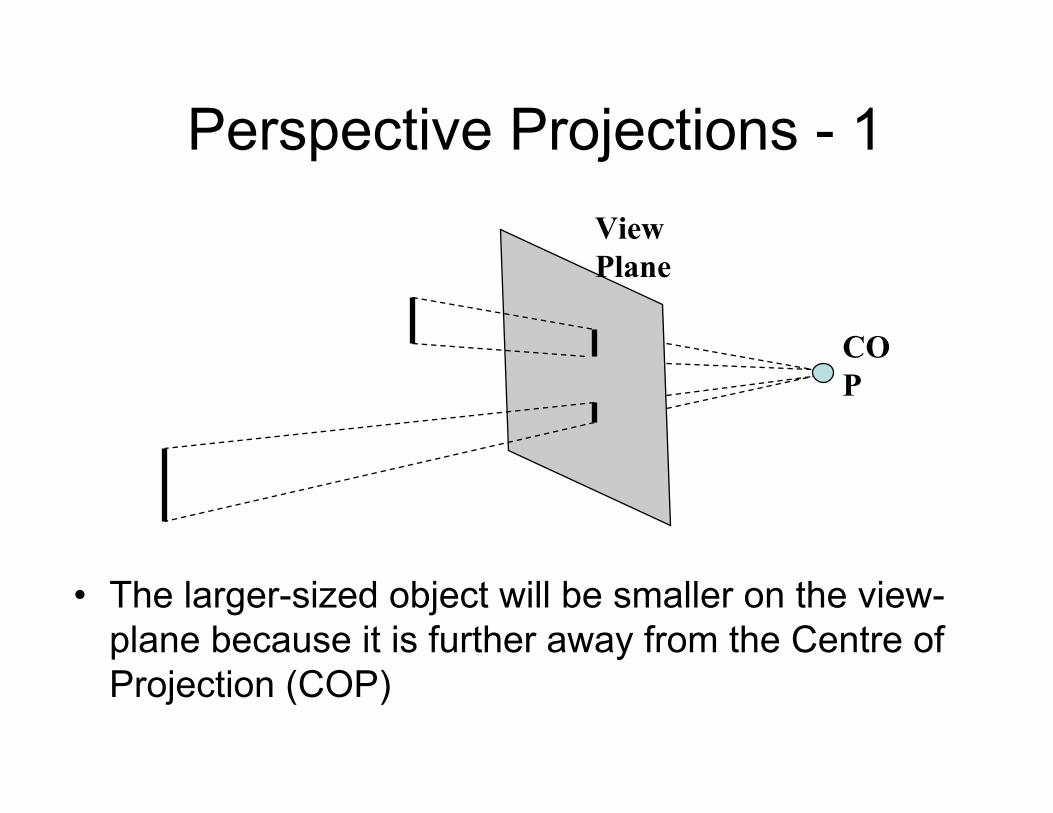
Perspective Projections - 1
• The larger-sized object will be smaller on the view-plane because it is further away from the Centre of Projection (COP)
COP
ViewPlane
ipbuker_graph07
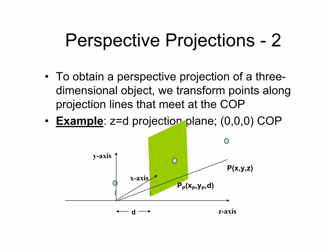
Perspective Projections - 2
• To obtain a perspective projection of a three-dimensional object, we transform points along projection lines that meet at the COP
• Example: z=d projection plane; (0,0,0) COP
z-axis
PP(xP,yP,d)
y-axis
d
P(x,y,z)x-axis
ipbuker_graph07
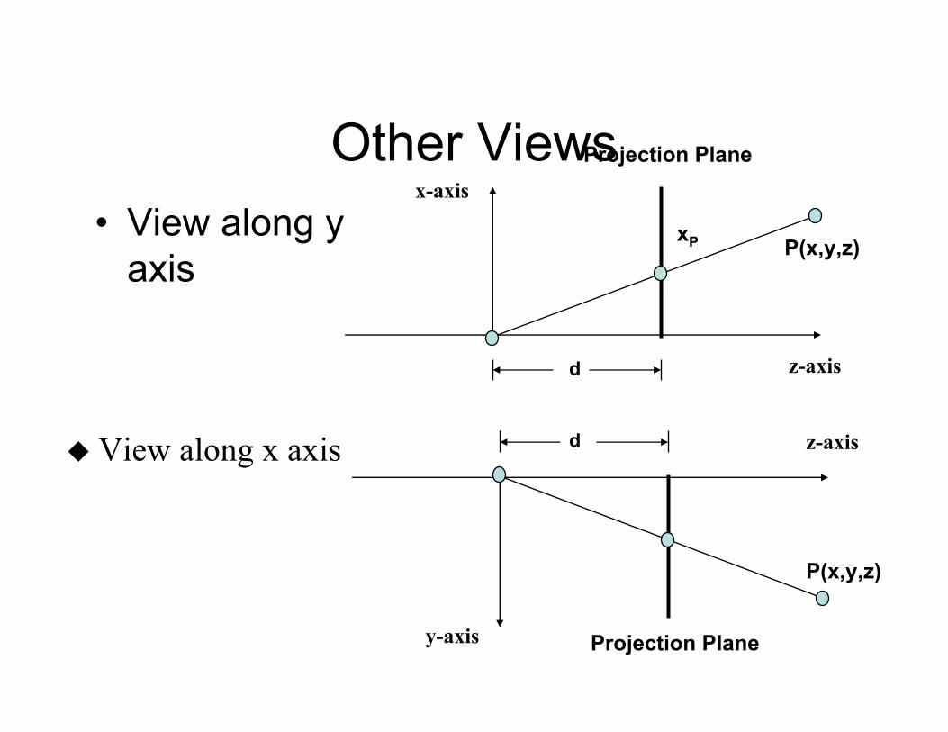
Other Views• View along y
axis
z-axis
xP
x-axis
d
P(x,y,z)
Projection Plane
View along x axis
Projection Plane
d z-axis
y-axis
P(x,y,z)
ipbuker_graph07
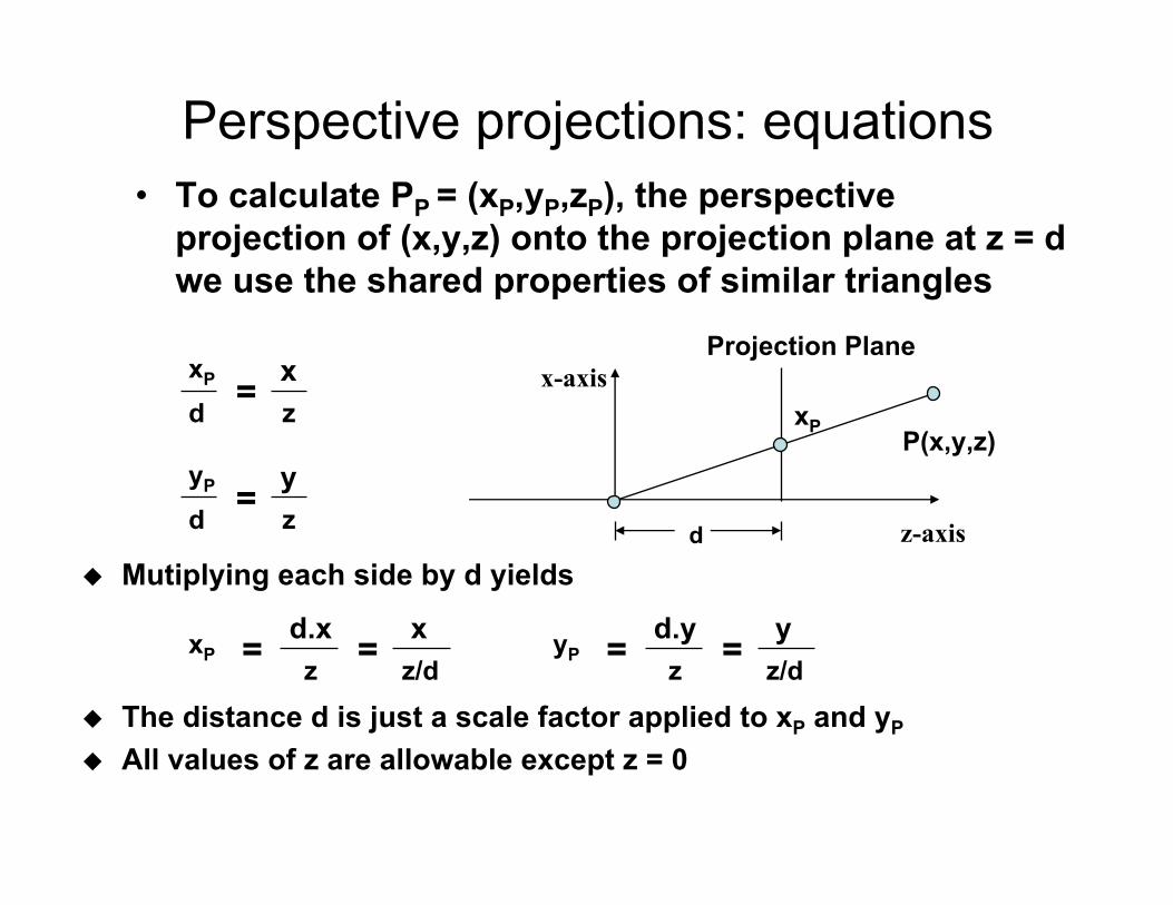
Perspective projections: equations• To calculate PP = (xP,yP,zP), the perspective
projection of (x,y,z) onto the projection plane at z = d we use the shared properties of similar triangles
=dxP
zx
z-axis
xP
x-axis
d
P(x,y,z)
Projection Plane
=dyP
zy
Mutiplying each side by d yields
=xPz
d.x = z/dx =yP
zd.y = z/d
y
The distance d is just a scale factor applied to xP and yP
All values of z are allowable except z = 0
ipbuker_graph07
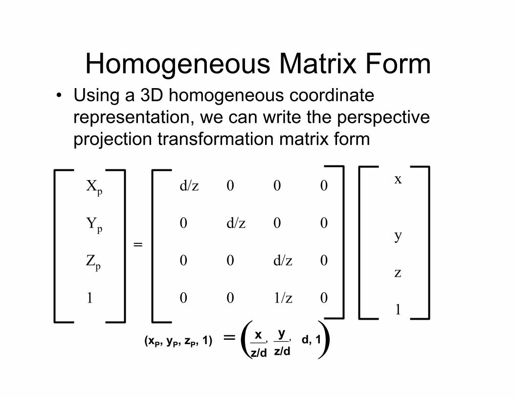
Homogeneous Matrix Form• Using a 3D homogeneous coordinate
representation, we can write the perspective projection transformation matrix form
d/z 0 0 0
0 d/z 0 0
0 0 d/z 0
0 0 1/z 0
=
Xp
Yp
Zp
1
x
y
z
1
z/dx ,(xP, yP, zP, 1) =
z/dy ,( )d, 1
ipbuker_graph07
Projection Equations Cont.• This makes sense intuitively: the further
away from the origin (our COP) a point P is, the larger its z value
• By dividing the x and y co-ordinates of every point of an object by the z coordinate means that objects further away will have each x and y divided by a larger number, and therefore the projection onto the projection plane will be much smaller than objects that are closer to the COP (in this case the origin)