gpon fundamentals vvvip
TRANSCRIPT
8/3/2019 GPON Fundamentals VVVIP
http://slidepdf.com/reader/full/gpon-fundamentals-vvvip 1/15
GPON Fundamentals
GPON stands for Gigabit Passive Optical Networks. GPON is defined by ITU-T
recommendation series G.984.1 through G.984.6. GPON can transport not only
Ethernet, but also ATM and TDM (PSTN, ISDN, E1 and E3) traffic. GPON networkconsists of mainly two active transmission equipments, namely- Optical Line
Termination (OLT) and Optical Network Unit (ONU) or Optical Network Termination
(ONT). GPON supports triple-play services, high-bandwidth, long reach (upto 20km),
etc.
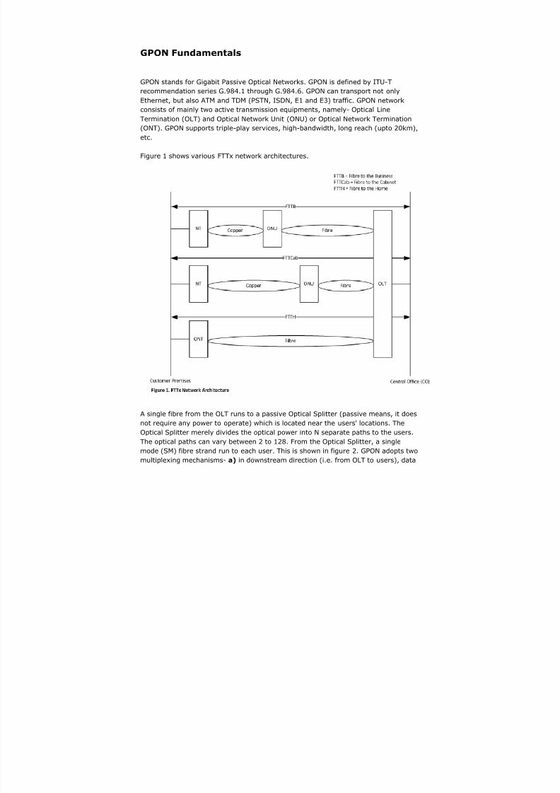
Figure 1 shows various FTTx network architectures.
A single fibre from the OLT runs to a passive Optical Splitter (passive means, it does
not require any power to operate) which is located near the users' locations. The
Optical Splitter merely divides the optical power into N separate paths to the users.
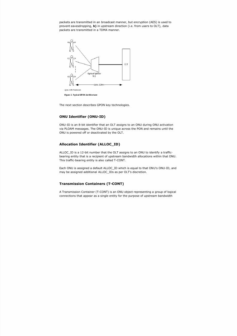
The optical paths can vary between 2 to 128. From the Optical Splitter, a single
mode (SM) fibre strand run to each user. This is shown in figure 2. GPON adopts two
multiplexing mechanisms- a) in downstream direction (i.e. from OLT to users), data
8/3/2019 GPON Fundamentals VVVIP
http://slidepdf.com/reader/full/gpon-fundamentals-vvvip 2/15
packets are transmitted in an broadcast manner, but encryption (AES) is used to
prevent eavesdropping, b) in upstream direction (i.e. from users to OLT), data
packets are transmitted in a TDMA manner.
The next section describes GPON key technologies.
ONU Identifier (ONU-ID)
ONU-ID is an 8-bit identifier that an OLT assigns to an ONU during ONU activationvia PLOAM messages. The ONU-ID is unique across the PON and remains until the
ONU is powered off or deactivated by the OLT.
Allocation Identifier (ALLOC_ID)
ALLOC_ID is a 12-bit number that the OLT assigns to an ONU to identify a traffic-
bearing entity that is a recipient of upstream bandwidth allocations within that ONU.
This traffic-bearing entity is also called T-CONT.
Each ONU is assigned a default ALLOC_ID which is equal to that ONU's ONU-ID, andmay be assigned additional ALLOC_IDs as per OLT's discretion.
Transmission Containers (T-CONT)
A Transmission Container (T-CONT) is an ONU object representing a group of logical
connections that appear as a single entity for the purpose of upstream bandwidth

8/3/2019 GPON Fundamentals VVVIP
http://slidepdf.com/reader/full/gpon-fundamentals-vvvip 3/15
assignment on the PON. For a given ONU, the number of supported T-CONTs is fixed.
The ONU autonomously creates all the supported T-CONT instances during ONU
activation. The OLT discovers the number of T-CONT instances supported by a given
ONU.
To activate a T-CONT instance to carry upstream user traffic, the OLT has toestablish a mapping between T-CONT instance and an ALLOC_ID, which has been
previously assigned to the ONU via PLOAM messages. Any ALLOC_ID assigned to the
ONU, including the default ALLOC_ID, can be associated with single user traffic T-
CONT.
There are 5 types of T-CONTs which can be allocated to the user-
1. Type 1: This T-CONT is of fixed bandwidth type and mainly used for services
sensitive to delay and high priority like VOIP.
2. Type 2 and Type 3: Both T-CONT are of guaranteed bandwidth types and
mainly used for video services and data services of higher priorities.
3. Type 4: This T-CONT is of best-effort type and mainly used for data services
such as Internet and services of low priority which do not require high
bandwidth.
4. Type 5: This T-CONT is of mixed type, involving all bandwidth types and
bearing all services.
Dynamic Bandwidth Allocation (DBA)
The OLT is responsible for allocating upstream bandwidth to the ONUs. Because the
access network is shared, ONU upstream transmissions could collide if they were
transmitted at random times. ONUs can be located at varying distances from the
OLT, and hence the transmission delay from each ONU is unique. The OLT measures
delay and sets a register in each ONU via PLOAM (Physical Layer Operations,
Administration and Maintenance) messages to equalize its delay with respect to all
other ONUs on the access network. This is called Ranging.
Once the delay of all ONUs have been set, the OLT transmits grants to individual
ONUs. A grant is permission to use a defined interval of time for upstream
transmission. The grant map is dynamically re-calculated every few milliseconds. Themap allocates bandwidth to all ONUs such that each ONU receives timely bandwidth
for its needs.
DBA is a methodology that allows quick adoption of users' bandwidth allocation
based on current traffic requirements and it is especially good for dealing with bursty
upstream traffic. GPON uses TDMA for managing upstream access by ONUs, and at
any one point in time, TDMA provides unshared timeslots (upstream bandwidth over
8/3/2019 GPON Fundamentals VVVIP
http://slidepdf.com/reader/full/gpon-fundamentals-vvvip 4/15
time) to each ONU for upstream transmission.
DBA allows upstream timeslots to shrink and grow based on the distribution of
upstream traffic loads. DBA functions on T-CONTs, which are upstream timeslots,
and each is identified by a particular ALLOC_ID. An ONU must have atleast one T-
CONT, but most have several T-CONTs, each with its own priority or traffic class, andeach corresponds to a particular upstream timeslot on the PON. Without DBA support
on the OLT, upstream bandwidth is statically assigned to T-CONTs, which cannot be
shared, and can be changed only through a management system.
There are two forms of DBA - Status Reporting DBA (SR-DBA) and Non-Status
Reporting DBA (NSR-DBA).
In NSR-DBA, an OLT constantly allocates a small amount of extra bandwidth to each
ONU. If the ONU has no traffic to send, it transmits idle frames. If the OLT observes
that an ONU is not sending idle frames, it increases the bandwidth allocation to that
ONU. Once that ONU starts sending idle frames, the OLT reduces its allocation
accordingly. NSR-DBA has the advantage that the ONUs need not be aware of DBA,
however, its disadvantage is that there is no way for the OLT to know how to allocate
bandwidth to several ONUs in the most efficient way.
SR-DBA involves explicit T-CONT buffer status provided by the ONUs when OLT polls
them. In this method, the OLT solicits T-CONT buffer status, and the ONUs respond
with a separate report for each assigned T-CONT. The report contains the data
currently waiting in T-CONTs in the specified time slots. OLT receives the status
(DBA) report, re-calculates bandwidth allocation (BW Map) through DBA algorithm
and sends new BW Map to the ONUs in-band with downstream traffic. The ONU
receives the BW Map from OLT and sends the data in the specified time slots. When
an ONU has no information to send, upon receiving a grant from the OLT, it sends an
idle cell upstream to indicate that its buffer is empty. This informs the OLT that the
grants for that T-CONT can be assigned to other T-CONTs. If an ONU has a long
queue waiting in its buffer, the OLT can assign multiple T-CONTs to that ONT.
GPON Transmission Convergence (TC) Layer
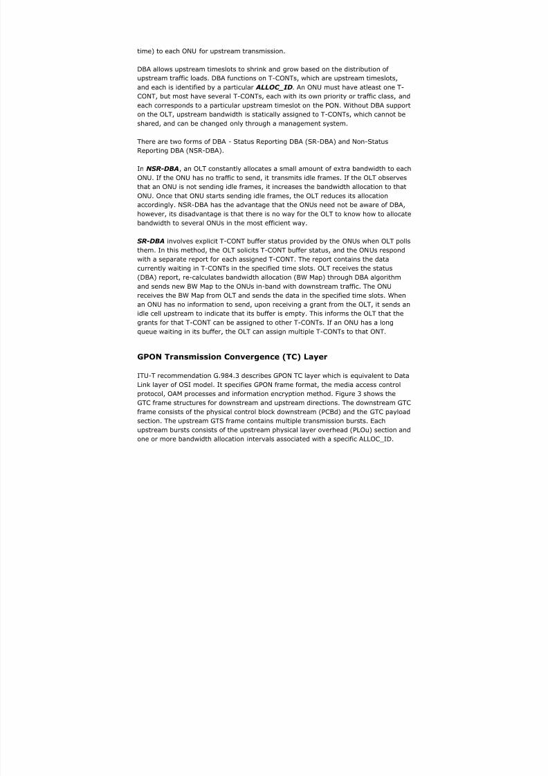
ITU-T recommendation G.984.3 describes GPON TC layer which is equivalent to Data
Link layer of OSI model. It specifies GPON frame format, the media access controlprotocol, OAM processes and information encryption method. Figure 3 shows the
GTC frame structures for downstream and upstream directions. The downstream GTC
frame consists of the physical control block downstream (PCBd) and the GTC payload
section. The upstream GTS frame contains multiple transmission bursts. Each
upstream bursts consists of the upstream physical layer overhead (PLOu) section and
one or more bandwidth allocation intervals associated with a specific ALLOC_ID.
8/3/2019 GPON Fundamentals VVVIP
http://slidepdf.com/reader/full/gpon-fundamentals-vvvip 5/15
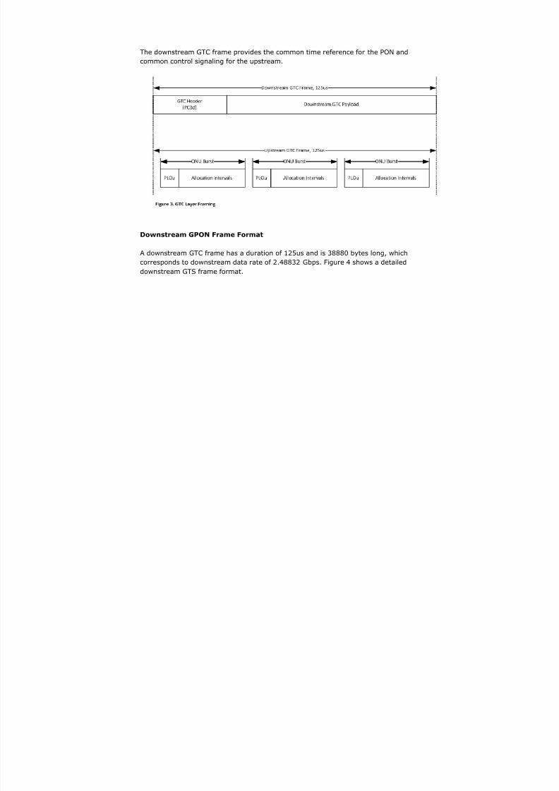
The downstream GTC frame provides the common time reference for the PON and
common control signaling for the upstream.
Downstream GPON Frame Format
A downstream GTC frame has a duration of 125us and is 38880 bytes long, which
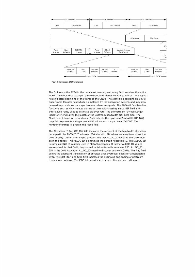
corresponds to downstream data rate of 2.48832 Gbps. Figure 4 shows a detailed
downstream GTS frame format.
8/3/2019 GPON Fundamentals VVVIP
http://slidepdf.com/reader/full/gpon-fundamentals-vvvip 6/15
The OLT sends the PCBd in the broadcast manner, and every ONU receives the entire
PCBd. The ONUs then act upon the relevant information contained therein. The Psync
field indicates beginning of the frame to the ONUs. The Ident field contains an 8-KHz
Superframe Counter field which is employed by the encryption system, and may also
be used to provide low rate synchronous reference signals. The PLOAMd field handles
functions such as OAM-related alarms or threshold-crossing alerts. BIP field is Bit
Interleaved Parity used to estimate bit error rate. The downstream Payload Length
indicator (Plend) gives the length of the upstream bandwidth (US BW) map. The
Plend is sent twice for redundancy. Each entry in the Upstream Bandwidth (US BW)
map field represents a single bandwidth allocation to a particular T-CONT. The
number of entries is given in the Plend field.
The Allocation ID (ALLOC_ID) field indicates the recipient of the bandwidth allocation
i.e. a particular T-CONT. The lowest 254 allocation ID values are used to address the
ONU directly. During the ranging process, the first ALLOC_ID given to the ONU mustbe in this range. This ALLOC-ID is known as the default Allocation ID. This ALLOC_ID
is same as ONU-ID number used in PLOAM messages. If further ALLOC_ID values
are required for that ONU, they should be taken from those above 255. ALLOC_ID
254 is the ONU Activation ALLOC_ID- used to discover unknown ONUs. The Flag field
allows the upstream transmission of physical layer overhead blocks for a designated
ONU. The Slot Start and Stop field indicates the beginning and ending of upstream
transmission window. The CRC field provides error detection and correction on
8/3/2019 GPON Fundamentals VVVIP
http://slidepdf.com/reader/full/gpon-fundamentals-vvvip 7/15
bandwidth allocation field.
The GTC payload field contains a series of GEM (GPON Encapsulation Method)
frames. The downstream GEM frame stream is filtered at the ONU based upon the
12-bit Port ID field contained in the header of each GEM frame. Each ONU is
configured to recognize which Port-IDs belong to it. The Port-ID uniquely identifies aGEM Frame.
Upstream GPON Frame Format
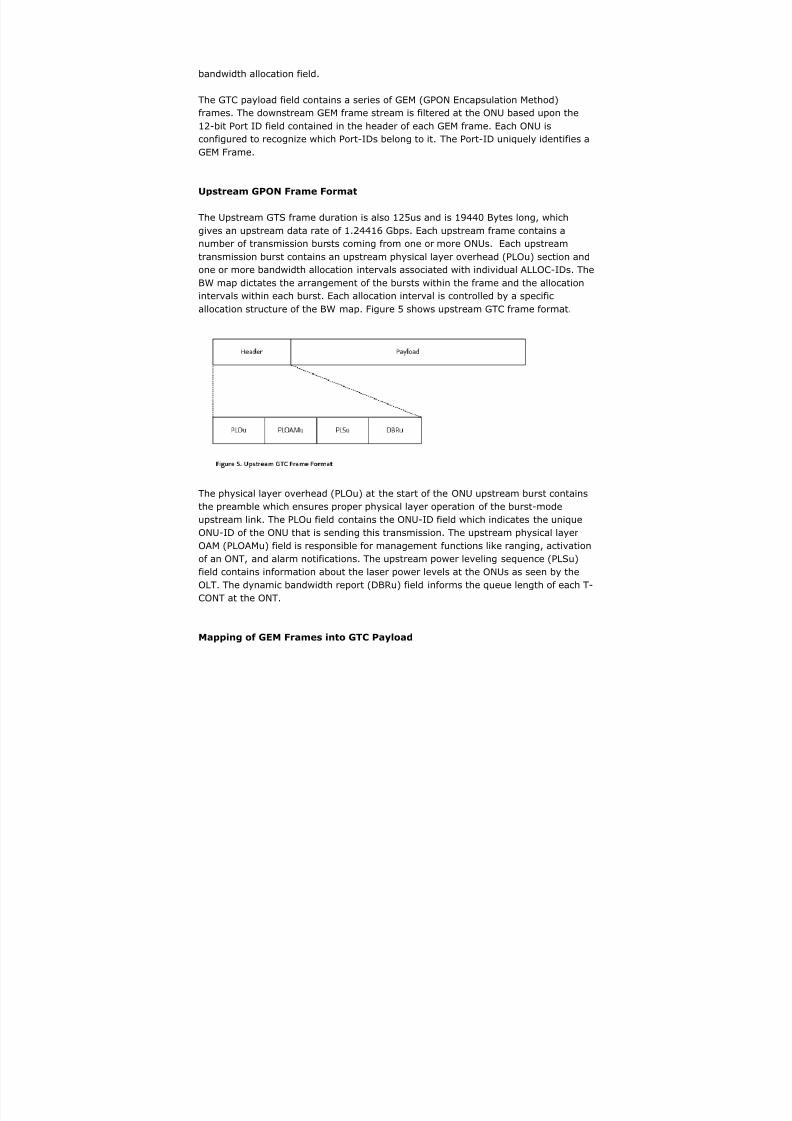
The Upstream GTS frame duration is also 125us and is 19440 Bytes long, which
gives an upstream data rate of 1.24416 Gbps. Each upstream frame contains a
number of transmission bursts coming from one or more ONUs. Each upstream
transmission burst contains an upstream physical layer overhead (PLOu) section and
one or more bandwidth allocation intervals associated with individual ALLOC-IDs. The
BW map dictates the arrangement of the bursts within the frame and the allocation
intervals within each burst. Each allocation interval is controlled by a specific
allocation structure of the BW map. Figure 5 shows upstream GTC frame format.
The physical layer overhead (PLOu) at the start of the ONU upstream burst contains
the preamble which ensures proper physical layer operation of the burst-mode
upstream link. The PLOu field contains the ONU-ID field which indicates the unique
ONU-ID of the ONU that is sending this transmission. The upstream physical layer
OAM (PLOAMu) field is responsible for management functions like ranging, activation
of an ONT, and alarm notifications. The upstream power leveling sequence (PLSu)field contains information about the laser power levels at the ONUs as seen by the
OLT. The dynamic bandwidth report (DBRu) field informs the queue length of each T-
CONT at the ONT.
Mapping of GEM Frames into GTC Payload
8/3/2019 GPON Fundamentals VVVIP
http://slidepdf.com/reader/full/gpon-fundamentals-vvvip 8/15
GEM traffic is carried over the GTC protocol in transparent fashion. In the
downstream direction, GEM frames are transmitted from the OLT to the ONUs using
the GTC frame payload section. The OLT may allocate as much duration as it needs
in the downstream, upto and including all of the downstream frame. The ONU filters
the incoming frames based on Port-ID. In the upstream direction, frames are
transmitted from ONU to OLT using the configured GEM allocation time. The ONUbuffers GEM frames as they arrive, and then sends them in bursts when allocated
time to do so by the OLT. The OLT receives the frames and multiplexes them with
the frames from other ONUs.
Ethernet over GEM
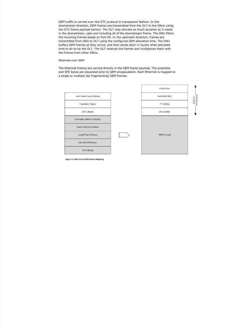
The Ethernet frames are carried directly in the GEM frame payload. The preamble
and SFD bytes are discarded prior to GEM encapsulation. Each Ethernet is mapped to
a single or multiple (by fragmenting) GEM frames.
8/3/2019 GPON Fundamentals VVVIP
http://slidepdf.com/reader/full/gpon-fundamentals-vvvip 9/15
GPON: VLANs and GEM Ports
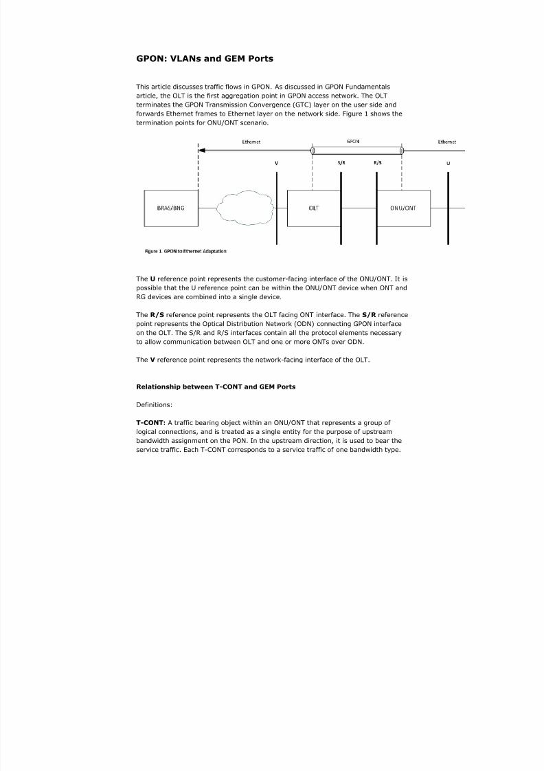
This article discusses traffic flows in GPON. As discussed in GPON Fundamentals
article, the OLT is the first aggregation point in GPON access network. The OLTterminates the GPON Transmission Convergence (GTC) layer on the user side and
forwards Ethernet frames to Ethernet layer on the network side. Figure 1 shows the
termination points for ONU/ONT scenario.
The U reference point represents the customer-facing interface of the ONU/ONT. It is
possible that the U reference point can be within the ONU/ONT device when ONT andRG devices are combined into a single device.
The R/S reference point represents the OLT facing ONT interface. The S/R reference
point represents the Optical Distribution Network (ODN) connecting GPON interface
on the OLT. The S/R and R/S interfaces contain all the protocol elements necessary
to allow communication between OLT and one or more ONTs over ODN.
The V reference point represents the network-facing interface of the OLT.
Relationship between T-CONT and GEM Ports
Definitions:
T-CONT: A traffic bearing object within an ONU/ONT that represents a group of
logical connections, and is treated as a single entity for the purpose of upstream
bandwidth assignment on the PON. In the upstream direction, it is used to bear the
service traffic. Each T-CONT corresponds to a service traffic of one bandwidth type.

8/3/2019 GPON Fundamentals VVVIP
http://slidepdf.com/reader/full/gpon-fundamentals-vvvip 10/15
Each bandwidth type has its own QoS feature.
ALLOC_ID: Each T-CONT is identified by the ALLOC_ID uniquely. The ALLOC_ID
ranges from 0 to 4095. It is allocated by OLT i.e. a T-CONT can only be used by one
ONU/ONT per PON interface on the OLT.
GEM Port: A GPON Encapsulation Method (GEM) port is a virtual port for performing
GEM encapsulation for transmitting frames between the OLT and the
ONU/ONT. Each different traffic-class (TC) per UNI is assigned a different
GEM Port. Each T-CONT consists of one or more GEM Ports. Each GEM port bears
one kind of service traffic i.e. a T-CONT type.
GEM Port ID: Each GEM Port is identified by a port ID uniquely. The Port ID ranges
from 0 to 4095. It is allocated by the OLT i.e a GEM port can only be used by a single
ONU/ONT per PON interface on the OLT.
Figure 2 shows the relationship between T-CONT and GEM Ports.
Between the ONT and OLT is the ODN, and Ethernet frames are carried over it
through the use of GEM Channels. GPON has GEM channels as part of its GTC layer.
The GEM channels carry variable-length Ethernet frames. GEM channels are
identified by GEM Port IDs. This identifier is assigned by OLT upon creation of a new
channel and is only valid during the entire life-cycle of the channel. Each GPON
interface for a given ONT can have several GEM Ports. A GEM Port ID is unique per

8/3/2019 GPON Fundamentals VVVIP
http://slidepdf.com/reader/full/gpon-fundamentals-vvvip 11/15
GPON interface and represents a specific traffic or group of flows between the OLT
and the ONT.
There are 2 types of GEM Channels:
Downstream-only GEM Channels - These channels are used to transmitdownstream broadcast/multicast traffic from OLT to all ONTs. The ONTs
identify traffic meant for them based on GEM Port ID.
Bi-directional GEM Channels - These channels are used for upstream and
downstream traffic between the OLT and the ONT. The frames are transmitted
from the OLT into the GPON interface and are forwarded only on the U
interface of the ONT on which that GEM Port has been assigned.
GEM Ports are used to differentiate among traffic classes (TCs). A U interface may
have several GEM Ports associated with it that support different TCs. Thus, within a
GPON interface, each GEM Port carries one or more traffic flows associated with a
specific TC.
On U interface, traffic is classified into VLANs with various Ethernet priorities based
on: Physical Port, VLAN ID, 802.1p bits, &/or DSCP. Once the traffic has been
assigned a VLAN and COS (802.1p) values, these two values are used to select an
upstream GEM Port so that QoS can be applied to the flows carried by the GEM Port.
A GEM Port always belongs to a single T-CONT. In downstream direction, the ONT
forwards the traffic received by GEM Ports to appropriate U interface.
1:1 VLAN
In a 1:1 VLAN architecture, the ONT maps each 1:1 VLAN into a unique U interface.
There are 2 variations on tag assignment at V interface in upstream direction - the
traffic at V interface could be double-tagged or single-tagged.
For double-tagged VLANs at V, the ONT can either assign a C-VLAN ID or
translate a C-VLAN ID. The OLT adds the S-VLAN ID. (Subscriber 1 in Figure
3)
For double-tagged VLANs at V, the ONT can assign S-C VLAN IDs to incoming
traffic, and the OLT passes through the traffic. (Subscriber 2 in Figure 3) For single-tagged VLAN at V, the ONT adds the S-VLAN ID or translates an
incoming tag to S-VLAN ID, and the OLT passes through the traffic.
(Subscriber 3 in Figure 3)
In the downstream direction, the OLT removes the outer tag or passes through the

8/3/2019 GPON Fundamentals VVVIP
http://slidepdf.com/reader/full/gpon-fundamentals-vvvip 12/15
traffic to proper GEM port based on the tag value and priority bits. The ONT removes
the tags and forwards frames from the GEM port to its associated U interface.
N:1 VLAN
For N:1 VLAN model, the ONT always adds the S-VLAN ID or translate an incoming
tag to S-VLAN ID for upstream traffic. The OLT will pass-through any upstream
traffic with S-VLAN ID on them. In the downstream direction, the OLT will pass-
through traffic with S-VLAN ID to ONT by determining GEM Port based on MAC
address and priority bits. If the GEM Port cannot be determined, then the frame is
flooded using the unidirectional GEM Port associated with the S-VLAN ID. The ONT
will remove the tag and forward frames from the GEM Port to appropriate U
interface. For N:1 model, traffic is always single-tagged at V interface.
8/3/2019 GPON Fundamentals VVVIP
http://slidepdf.com/reader/full/gpon-fundamentals-vvvip 13/15
QoS and Traffic Management
As seen from figure 1, the GPON link connects the OLT and ONTs to transport
Ethernet services. Please note that GPON can also encapsulate ATM and TDM (E1,E3) services. The GTC Adaptation sublayer maps Ethernet frames into GPON GEM
frames. A QoS mechanism is required in GEM to support Ethernet QoS (i.e. 802.1p
bits). In order to provide QoS, two mechanisms are employed-
Classification of traffic into traffic classes
Forwarding the traffic classes into GEM Ports and T-CONTs configured to
emulate Ethernet QoS service
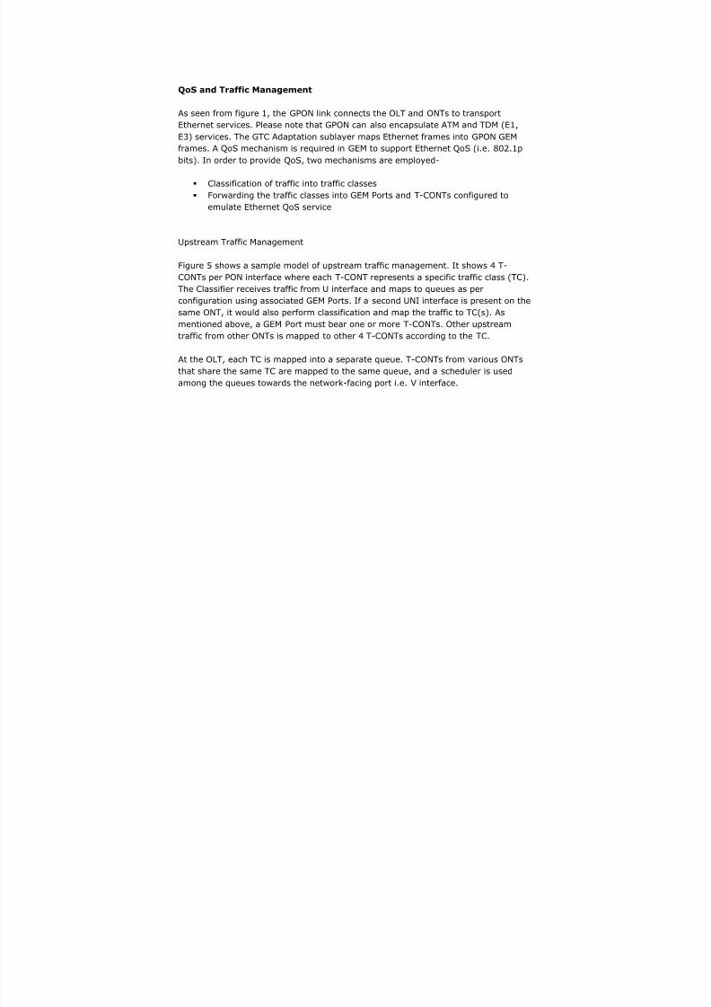
Upstream Traffic Management
Figure 5 shows a sample model of upstream traffic management. It shows 4 T-
CONTs per PON interface where each T-CONT represents a specific traffic class (TC).
The Classifier receives traffic from U interface and maps to queues as per
configuration using associated GEM Ports. If a second UNI interface is present on the
same ONT, it would also perform classification and map the traffic to TC(s). As
mentioned above, a GEM Port must bear one or more T-CONTs. Other upstream
traffic from other ONTs is mapped to other 4 T-CONTs according to the TC.
At the OLT, each TC is mapped into a separate queue. T-CONTs from various ONTs
that share the same TC are mapped to the same queue, and a scheduler is used
among the queues towards the network-facing port i.e. V interface.
8/3/2019 GPON Fundamentals VVVIP
http://slidepdf.com/reader/full/gpon-fundamentals-vvvip 14/15
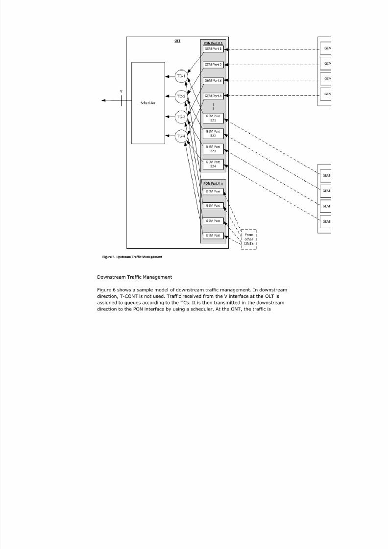
Downstream Traffic Management
Figure 6 shows a sample model of downstream traffic management. In downstream
direction, T-CONT is not used. Traffic received from the V interface at the OLT is
assigned to queues according to the TCs. It is then transmitted in the downstream
direction to the PON interface by using a scheduler. At the ONT, the traffic is

8/3/2019 GPON Fundamentals VVVIP
http://slidepdf.com/reader/full/gpon-fundamentals-vvvip 15/15
classified again and placed into appropriate queues for each U interface. A scheduler
is used to transmit frames to the U interface.