gpal / x-ray >> - effecto group spa | advanced ...€¢ organi di presa a corsa parallela a...
TRANSCRIPT

A d v a n c e d C o m p o n e n t s f o r A u t o m a t i o n
tecnomors spa. - Via Roma 141/143 - 28017 San Maurizio d’Opaglio (NO) - Italytel.: 0322 96142 - fax.: 0322 967453 - e mail : [email protected]
A46.2
• ORGANI DI PRESA A CORSA PARALLELA A DUE GRIFFE• 2 Finger parallel grippers• 2-Finger-Parallelgreifer
• Organes de préhension à course parallèle, à deux mors
GPAL / X-RAY >>

A d v a n c e d C o m p o n e n t s f o r A u t o m a t i o n f o r A u t o m a t i o n
tecnomors spa. - Via Roma 141/143 - 28017 San Maurizio d’Opaglio (NO) - Italytel.: 0322 96142 - fax.: 0322 967453 - e mail : [email protected]
A46.3
• ORGANI DI PRESA A CORSA PARALLELA A DUE GRIFFE• 2 Finger parallel grippers• 2-Finger-Parallelgreifer
• Organes de préhension à course parallèle, à deux mors

tecnomors spa. - Via Roma 141/143 - 28017 San Maurizio d’Opaglio (NO) - Italytel.: 0322 96142 - fax.: 0322 967453 - e mail : [email protected]
A46.4
• Ca
ratt
eris
tiche
tecn
iche
X-R
AY•
Tech
nica
l spe
cific
atio
ns X
-RAY
• Te
chni
sche
Eig
ensc
haft
en X
-RAY
• Ca
ract
éris
tique
s te
chni
ques
X-R
AY
A d v a n c e d C o m p o n e n t s f o r A u t o m a t i o n
Organi di presa XRAY. Grande forza eresistenza al momento torcente.Il concetto XRAY è stato sviluppato perapplicazioni nelle quali i pezzi in movimen-to subiscono elevate accelerazioni o cherichiedono una particolare lunghezza epreciso posizionamento delle ganasce.Queste applicazioni sottopongono la pinzaa grandi sollecitazioni. Le pinze XRAY uti-lizzano un sistema di cuscinetti ceramici, lostesso sistema che è usato nell’attuatoreZaytran mod. LSA, per rendere indipen-denti la precisione dal sistema di posizio-namento della pinza. La guida su cuscinet-ti ceramici permette alle pinze di esserepiccole e leggere, nonostante esprimanouna forza di oltre 2500 N e sopportino unmomento torcente di 600 Nm. Le pinzeXRAY esprimono veramente: “Doppiaforza… metà grandezza” .
Sincronismo brevettato-Lunga durataIl sincronismo brevettato XRAY utilizzaZAYTRAN US, brevetto nr. 4591199. Laforza e la doppia elica sincronizzata sonosistemi indipendenti. La doppia elica lavo-ra solo per centrare le parti in ±0.025 mm.Tutta la forza di chiusura è fornita da duepistoni pneumatici. L’indipendenza dellaforza e del sistema di autocentrantismogarantiscono la precisione per oltre10.000.000 di cicli vitali della pinza.
XRAY Grippers. Extreme Force andTorque.The XRAY concept was developed forapplications that impart high accelerationto heavy objects or require extremely long,precisely positioned jaws. These applications put extreme stress onthe gripper. XRAY grippers use a ceramicbearing system, the same system that isused in ZAYTRAN high load LSA actua-tors, to isolate the precision jaw positio-ning system from jaw torque and force.The ceramic bearing rail allows the grip-pers to be small and light weight while deli-vering gripping force in excess of 2500N(560 pounds) and to tolerate jaw torque of600NM (405 ft-lb). XRAY grippers truly deliver: “Twice theforce...Half the size” .
Patented Synchronous Technology -Extended Life
The synchronous XRAY utilizes ZAYTRANUS patent number 4591199. The forceand synchronizing double helix are inde-pendent systems. The double helix worksonly to center the part to .025mm (±0.001inches). All of the gripping force is providedby two pistons that are driven pneumati-cally. The independence of the force andsynchronization systems provides preci-sion over the typical 10,000,000+ cycle lifeof the unit.
XRAY Greifer. Grösse Kraft undWiderstand wegen Momente.XRAY Begrief entwickelte sich fürAnwendungen, in denen die Stücke einerhohe Beschleunigung sich unterziehenoder die lange Backen brauchen. DieseAnwenkungen geben dem Greifer großenStorung. XRAY Greifer brauchen einenTonlagersystem, wie in ZaytranSchwenkeinheit LSA, um die Präzision freivon der Positioniereinrichtung des Greifeszu machen. Die Führungen auf dieTonlagern erlauben, daß die Greifer auchmit Kraft höhe 2500 N und Moment 600Nm kleine und leicht sind. Die XRAY Greifer haben wirklich:“Doppelte Kraft....Halb Masse” .
Patentierter Synchronismus-LangeDauerDer XRAY Synchronismus braucht ZAY-TRAN US Patent Nr.4591199. Die Kraftund der Doppelschraub sind selbständingund synchronisiert. Das Doppelschraubarbeit nur um die Teile ±0.025 Mm zu zen-trieren. Die Schließkraft kommt von 2pneumatischen Kolben. Die Freiheit derKraft und des selbstzentrierendenSystems erlaubt die Präzision weiter10.000.000 Greiflebenzyklus.
Pinces Xray - Grande puissance etrésistance au moment de torsionOn a développé le concept XRAY pour lesapplications dans lesquelles les piècessubissent une haute accélération ou dansles applications qui nécessitent précisiond’application et une longuer particulièredes griffes. Cettes applications soumettentla pince à hautes sollicitations. Les pincesXRAY utilisent un système des roulementsen céramique, le même système qui estutilisé par l’unité rotatif Zaytran mod. LSA,pour rendre la précision indépendante du
système de positionnement de la pince. Laguide sur roulements en céramique per-mets aux pinces d’être petites et légèresaussi si expriment une force majore de2500 N et supportent un moment de tor-sion de 600 Nm.Les pinces XRAY expriment réellement:“Double force… a moitie taille” .
Synchronisme breveté - longue duréeLe synchronisme breveté XRAY utiliseZAYTRAN US brevet nr. 4591199. La forceet la double hélice synchronisé sont systè-mes indépendants. La double hélices tra-vaille seulement pour centrer les piècesdans ±0,025 mm. Toute la force de serrageest donnée par deux pistons pneumati-ques. L’indépendence de la force et dusystème à centrage automatique permet-tent une précision de plus de 10,000,000cycles d’usinages de la pince.
A d v a n c e d C o m p o n e n t s f o r A u t o m a t i o n f o r A u t o m a t i o n
tecnomors spa. - Via Roma 141/143 - 28017 San Maurizio d’Opaglio (NO) - Italytel.: 0322 96142 - fax.: 0322 967453 - e mail : [email protected]
A46.5
• Ca
ratt
eris
tiche
tecn
iche
X-R
AY•
Tech
nica
l spe
cific
atio
ns X
-RAY
• Te
chni
sche
Eig
ensc
haft
en X
-RAY
• Ca
ract
éris
tique
s te
chni
ques
X-R
AY
Robustezza a basso costo.XRAY trae vantaggio dallo sviluppo suglistudi dei materiali usati e della tecnologiasull’automazione, offrendo nuovi valori ditenacità ed efficienza di costo. Il costodelle pinze XRAY è minimizzato dall’uso dicilindri commerciali in acciaio inossidabile.Questi cilindri includono anelli magneticiper una maggiore versatilità del controllodella posizione. Una rigidità ineguagliabile è ottenuta com-binando una barra di base con le proprie-tà dei cuscinetti ceramici Zaytran. Il siste-ma di antirotazione delle griffe è ottenutocon le guide su cuscinetti in polyamideche conferiscono precisione meccanicasulla struttura portante in alluminio. Tuttiquesti organi in movimento della XRAYsono lubrificati permanentemente.La flessibilità dell’applicazione dell’XRAYè realizzata con l’uso di una struttura por-tante in alluminio estruso che provvede amolteplici funzioni: per il montaggio dellapinza, per il montaggio dei sensori sullapinza, per contenere il peso della pinza .
Rugged Construction-Low cost ofOwnershipXRAY takes advantage of dynamic deve-lopments in both material science andautomation technology to offer new hori-zons of toughness and cost efficiency. Thecost of ownership of the XRAY is minimi-zed by the use of off-the-shelf stainlesssteel cylinders. These cylinders includemagnetic sensing rings for enhanced flexi-bility in sensing. Unparalleled rigidity is achieved by com-
bining a 32mm ground rod andZAYTRAN’s proprietary ceramic bearingtechnology. Anti-rotation of the jaw moun-ting system is achieved with polyamideimide bearings running in guides that areprecision machined in the extruded back-bone of the system. All of these movingmembers are lubricated for the life of theXRAY.The application flexibility of the XRAY isextended by the use of an extruded alumi-num backbone that provides multipleoptions for mounting the gripper andmounting sensors to the gripper as well asreducing the weight of the gripper.
Stärke um billiger PreisXRAY zieht aus der Forschung dergebrauchten Materielle und derAutomaziontechnologie, um neueZähigkeitwerte und niedrigen Preis zu bie-ten. XRAY Kost ist durch die Nutzung derlaufeden Zylindern aus rostfreim Stahl ver-mindert. Diese Zylindern habenMagnetringe, um eine Hochvielseitigkeitdes Posizionskontrols zu erreichen. Die unerreichbare Steifheit ist durch eineUntersatzstange mit Zaytran TonlagerEigenschaften erlaubt. Die Führungen aufPolyamidlagern erlauben denAntidrehsystem der Backen . Alle dieseElementen werden von XRAY permanentgeschmiert sein.Die Biegsamkeit der XRAY Anmerkungenist mit einer Struktur aus sanggepreßtemAlluminium realisiert, um verschiedeneFunktionen zu sorgen: für Greifmontage,für Sensorenmontage auf den Greifer, fürGreifgewicht zu enthalten.
Robustesse à bon marchéXRAY tire profit du développement desétudes sur les matérieaux emploiés et de latechnologie de l’automation, en offrant nou-veaux valeurs de ténacité et efficience deprix. Le prix de la pince XRAY est minimiségrâce à l’emploi de cylindres commerciauxen acier inoxydable. Ces cylindre ont desbagues magnétiques pour augmenter lacapacité du controlle de la position.
Une rigidité inégalable est obtenue en com-binant une barre de base avec les caracté-ristiques des roulements en céramiqueZaytran. Le système anti-rotation des grif-fes est obtenu avec les guides sur des rou-lements en polyamide, qui donnent préci-sion mécanique à la structure portante enaluminium.Toutes cettes pinces en mouvement de laXRAY ont une lubrification permanente.
La flexibilité de l’application de la pinceXRAY est réalisée avec l’emploi d’unearmature en aluminium extrudé, qui fournitbeaucoup de fonctions: pour monter lapince, pour monter les détecteurs sur lapince, pour contenir le poids de la pince
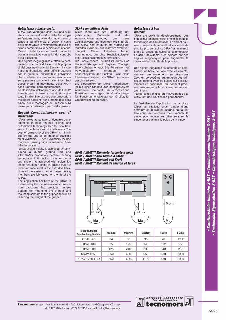
Modello/ModelMa:Nm Mb:Nm Mc:Nm F1:kg F2:kgBeschreibung/Modèle
GPAL -40 34 50 35 28 19.2
GPAL-100 75 125 140 112 77
GPAL-200 125 210 230 340 252
XRAY-1250 550 600 550 670 1000
XRAY-1250-LBR 550 600 1100 670 1000
GPAL / XRAY™ Momento torcente e forza GPAL / XRAY™ Jaw torque & forceGPAL / XRAY™ Moment und KraftGPAL / XRAY™ Moment de torsion et torce
Mc
Ma Ma Mc
Mb
F1 F2 F1 F2

tecnomors spa. - Via Roma 141/143 - 28017 San Maurizio d’Opaglio (NO) - Italytel.: 0322 96142 - fax.: 0322 967453 - e mail : [email protected]
A46.6
• Ca
ratt
eris
tiche
tecn
iche
X-R
AY•
Tech
nica
l spe
cific
atio
ns X
-RAY
• Te
chni
sche
Eig
ensc
haft
en X
-RAY
• Ca
ract
éris
tique
s te
chni
ques
X-R
AY
A d v a n c e d C o m p o n e n t s f o r A u t o m a t i o n
Dispositivo di bloccaggio irreversibi-le (opzionale)In applicazioni che necessitano che ilpezzo sia bloccato anche in assenza dialimentazione, il dispositivo di bloccaggioirreversibile fornisce una soluzione eccel-lente. Quando la pressione pneumaticaviene a mancare un dispositivo di bloc-caggio meccanico agisce sul sistema ditrasmissione. Così le griffe rimangono fre-nate in posizione.Con questo dispositivo opzionale è consi-gliabile utilizzare un tipo di ganasce dipresa pezzo che avvolgano almeno par-zialmente il pezzo stesso. In quanto levibrazioni possono causare movimentidelle griffe.Kit per interruttore di prossimità (opzionale)Il montaggio del kit per interruttore di pros-simità su scanalature a “T”, consente diottenere un’ampia gamma di posiziona-menti. E’ possibile montare i kits per inter-ruttori di prossimità cilindrici standard:Ø6.5mm., Ø12mm., Ø18mm.
Optional power-off brakeIn applications that require the part beheld even when pneumatic power is lost,the Power-Off Brake option provides anexcellent solution. When pneumatic pres-sure is removed from the option a spring isallowed to rotate a collar that engages acollet brake system on the helix. Thus, thejaws are braked in position.Either an encompassing jaw system or
jaws with compliance must be used withthis option. Jarring can cause some jawmovement.
Optional switch kitsThe switch mounting rail permits a broadrange of switch configurations to be used.Kits are available to mount 6.5mm, 12mm,and 18mm standard, tubular proximity swit-ches.
Inreversibelblocksystem (als Extra)Das Inreversibelblocksystem ist die Losungin Anvendungen, die die Sperrung desStückes auch ohne Speisung brauchen.Eine mechanische Klemmvorrichtungarbeit auf den Triebwerk, wann der pneu-matischer Druck ausbleibt.So die Backen bleiben in Stellunggebremmst.Mit dieser Extravorrichtung raten wir denBacken, die den Stück einwickeln, weil dieSchwingern die Backen belegen können.
Nahschalterbausätze (als Extra)Das Bausätzemontage für “T-Nut”Nahschalter erlaubt eine große Auswahl anStellungen. Es ist möglich die Ø6.5mm.,Ø12mm., Ø18mm. zylindrische Standard-Nahschalterbausätze einbauen.Dispositif de bloccage irréversible(optionnel)Pour les applications dans les quelles on a
besoin de fermer la pièce aussie quand onn’a pas d’alimentation, le dispositif de bloc-cage irréversible est une solution excellen-te. Quand la pression pneumatique vien àmanquer au bépérit un dispositif de blocca-ge mécanique agit sur le système de trans-mission. Ainsi les griffes restent freinées inposition.Avec ce dispositif optionnel est conseillableutiliser des griffes qui enroulent au moinspartiellement la pièce même, parce que lesvibrations pouvent causer des mouve-ments des griffes.
Kit pour interrupteur de proximité(optionnel) Le montage du kit pour l’interrupteur deproximité sur les raindures en té, consentd’obtenir une vaste gamme de positionne-ments. On peut monter les kit de proximitécylindriques standard: ø6.5mm., ø12mm., ø18mm.
Dispositivo di bloccaggio irreversibilePower-off brakeInreversibelblocksystemDispositif de bloccage irréversible
Kit per interruttore di prossimitàSwitch kitsNahschalterbausätzeKit pour interrupteur de proximité
A d v a n c e d C o m p o n e n t s f o r A u t o m a t i o n f o r A u t o m a t i o n
tecnomors spa. - Via Roma 141/143 - 28017 San Maurizio d’Opaglio (NO) - Italytel.: 0322 96142 - fax.: 0322 967453 - e mail : [email protected]
A46.7
• IN
FORM
AZIO
NI P
ER L
’ORD
INAZ
IONE
DEL
LE P
INZE
X-RA
Y•
Grip
per O
rder
ing
Info
rmat
ion
X-RA
Y•
Norm
en z
ur B
este
llung
des
Gre
ifes
X-RA
Y•
Info
rmat
ion
pour
ord
onne
r les
pin
ces
X-RA
Y
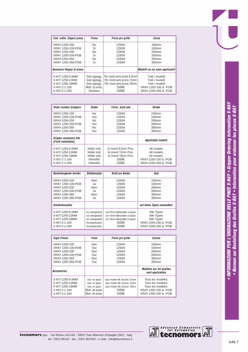
Cod. ordin. Organi presa Freno Forza per griffa Corsa
XRAY-1250-100 No 1250N 100mmXRAY 1250-100-POB Si 1250N 100mmXRAY-1250-200 No 1250N 200mmXRAY 1250-200-POB Si 1250N 200mmXRAY-1250-350 No 1250N 350mmXRAY 1250-350-POB Si 1250N 350mm
Accessori Organi di presa Modelli su cui sono applicabili
X-KIT-1250-6.5MM Solo appogg. Per mont.sens.pross.6.5mm Tutti i modelliX-KIT-1250-12MM Solo appogg. Per mont.sens.pross.12mm Tutti i modelliX-KIT-1250-18MM Solo appogg. Per mont.sens.pross.18mm Tutti i modelliX-INT-2:1-100 Molt. di press. 2500N XRAY-1250-100 & -POBX-INT-2:1-200 Hardware 2500N XRAY-1250-200 & -POB
Order number Grippers Brake Force, each jaw Stroke
XRAY-1250-100 No 1250N 100mmXRAY 1250-100-POB Yes 1250N 100mmXRAY-1250-200 No 1250N 200mmXRAY 1250-200-POB Yes 1250N 200mmXRAY-1250-350 No 1250N 350mmXRAY 1250-350-POB Yes 1250N 350mm
Gripper accessory kitsApplicable models(Field installable)
X-KIT-1250-6.5MM Holder only to mount 6.5mm Prox. All modelsX-KIT-1250-12MM Holder only to mount 12mm Prox. All modelsX-KIT-1250-18MM Holder only to mount 18mm Prox. All modelsX-INT-2:1-100 Intensifier 2500N XRAY-1250-100 & -POBX-INT-2:1-200 Intensifier 2500N XRAY-1250-200 & -POB
Bestellungkode Greifer Stoßdampfer Kraft pro Backe Hub
XRAY-1250-100 Nein 1250N 100mmXRAY 1250-100-POB Ja 1250N 100mmXRAY-1250-200 Nein 1250N 200mmXRAY 1250-200-POB Ja 1250N 200mmXRAY-1250-350 Nein 1250N 350mmXRAY 1250-350-POB Ja 1250N 350mm
Greiferbausätze auf diese Typen anwendbar
X-KIT-1250-6.5MM nur untergestützt um 6.5mm Nahschalter zu bauen Alle TypenX-KIT-1250-12MM nur untergestützt um 12mm Nahschalter zu bauen Alle TypenX-KIT-1250-18MM nur untergestützt um 18mm Nahschalter zu bauen Alle TypenX-INT-2:1-100 Druckübersetzer 2500N XRAY-1250-100 & -POBX-INT-2:1-200 Druckübersetzer 2500N XRAY-1250-200 & -POB
Sigle Pinces Frein Force par griffe Course
XRAY-1250-100 Non 1250N 100mmXRAY 1250-100-POB Oui 1250N 100mmXRAY-1250-200 Non 1250N 200mmXRAY 1250-100-POB Oui 1250N 200mmXRAY-1250-350 Non 1250N 350mmXRAY 1250-350-POB Oui 1250N 350mm
AccessoiresModèles sur les quelles
sont applicables
X-KIT-1250-6.5MM seul. en appui pour monter dét. de prox. 6.5mm Tous les modèlesX-KIT-1250-12MM seul. en appui pour monter dét. de prox. 12mm Tous les modèlesX-KIT-1250-18MM seul. en appui pour monter dét. de prox. 18mm Tous les modèlesX-INT-2:1-100 Mult. de press. 2500N XRAY-1250-100 & -POBX-INT-2:1-200 Mult. de press. 2500N XRAY-1250-200 & -POB

• CONTROLLO POSIZIONE APERTO-CHIUSO CON SENSORI (PROXIMITY) ESTERNI• Open-closed control position with external proximity switches
• Positionskontrolle “geöffnet”-”geschlossen mit kontaktlosen Sensoren• Contrôle de la position ouvert-fermé avec détecteurs extérieurs (de proximité)
A d v a n c e d C o m p o n e n t s f o r A u t o m a t i o n
tecnomors spa. - Via Roma 141/143 - 28017 San Maurizio d’Opaglio (NO) - Italytel.: 0322 96142 - fax.: 0322 967453 - e mail : [email protected]
C chiuso
A aperto B
• Le dimensioni sono indicative e suscettibili di variazioni per migliorie tecniche. Ci riserviamo di apportare modifiche senza preavviso • All dimensions are indicative and sub-ject to variation for technical upgrading. We reserve the right to make alterations without prior notification • Die Maßangaben sind indikativ und können sich bei technischenVerbesserung ändern. Wir behalten uns vor, ohne vorherige Benachrichtigung Änderungen vorzunehmen • Les dimensions sont fournies à titre indicatif; elles peuvent subir desvariations pour cause d’ameliorations techniques. Nous nous réservons le droit d’apporter des modifications sans préavis.
A46.8
• SCHEMA • Diagram • Schema • Schéma
• OR
GANI
DI P
RESA
A C
ORSA
PAR
ALLE
LA A
DUE
GRI
FFE
GPAL
• 2
Fin
ger p
aral
lel g
rippe
rs G
PAL
• 2
-Fin
ger-P
aral
lelg
reife
r GPA
L •
Orga
nes
de p
réhe
nsio
n à
cour
se p
aral
lèle
, à d
eux
mor
s GP
AL
Sigla - Code
Bezeichnung
Sigle A B C—————————————————————
GPAL-40 212 63 162GPAL-100 295.5 78 219.3GPAL-200 380.5 89 278.9
—————————————————————

• DISPOSITIVO DI SICUREZZA• Safety device
• Sicherrheits-vorrichtung• Dispositif de sécurité
A d v a n c e d C o m p o n e n t s f o r A u t o m a t i o n f o r A u t o m a t i o n
tecnomors spa. - Via Roma 141/143 - 28017 San Maurizio d’Opaglio (NO) - Italytel.: 0322 96142 - fax.: 0322 967453 - e mail : [email protected]
A46.9
• OR
GANI
DI P
RESA
A C
ORSA
PAR
ALLE
LA A
DUE
GRI
FFE
GPAL
• 2
Fin
ger p
aral
lel g
rippe
rs G
PAL
• 2
-Fin
ger-P
aral
lelg
reife
r GPA
L •
Orga
nes
de p
réhe
nsio
n à
cour
se p
aral
lèle
, à d
eux
mor
s GP
AL
• Le dimensioni sono indicative e suscettibili di variazioni per migliorie tecniche. Ci riserviamo di apportare modifiche senza preavviso • All dimensions are indicative and sub-ject to variation for technical upgrading. We reserve the right to make alterations without prior notification • Die Maßangaben sind indikativ und können sich bei technischenVerbesserung ändern. Wir behalten uns vor, ohne vorherige Benachrichtigung Änderungen vorzunehmen • Les dimensions sont fournies à titre indicatif; elles peuvent subir desvariations pour cause d’ameliorations techniques. Nous nous réservons le droit d’apporter des modifications sans préavis.
A apreC ch
iude
M8
Ø8H7
D
G
L
B
E
F
H
• SCHEMA • Diagram • Schema • Schéma
Sigla - Code
Bezeichnung
Sigle A B C D E F G H L—————————————————————————————————————
GPAL-40 1/8NPT 24 G1/8 11 12.5 25 75 35 -GPAL-100 1/4NPT 64.2 G1/4 42.5 15 30 60 45 -GPAL-200 3/8NPT 56 G3/8 49.8 15 30 70 50 140
—————————————————————————————————————

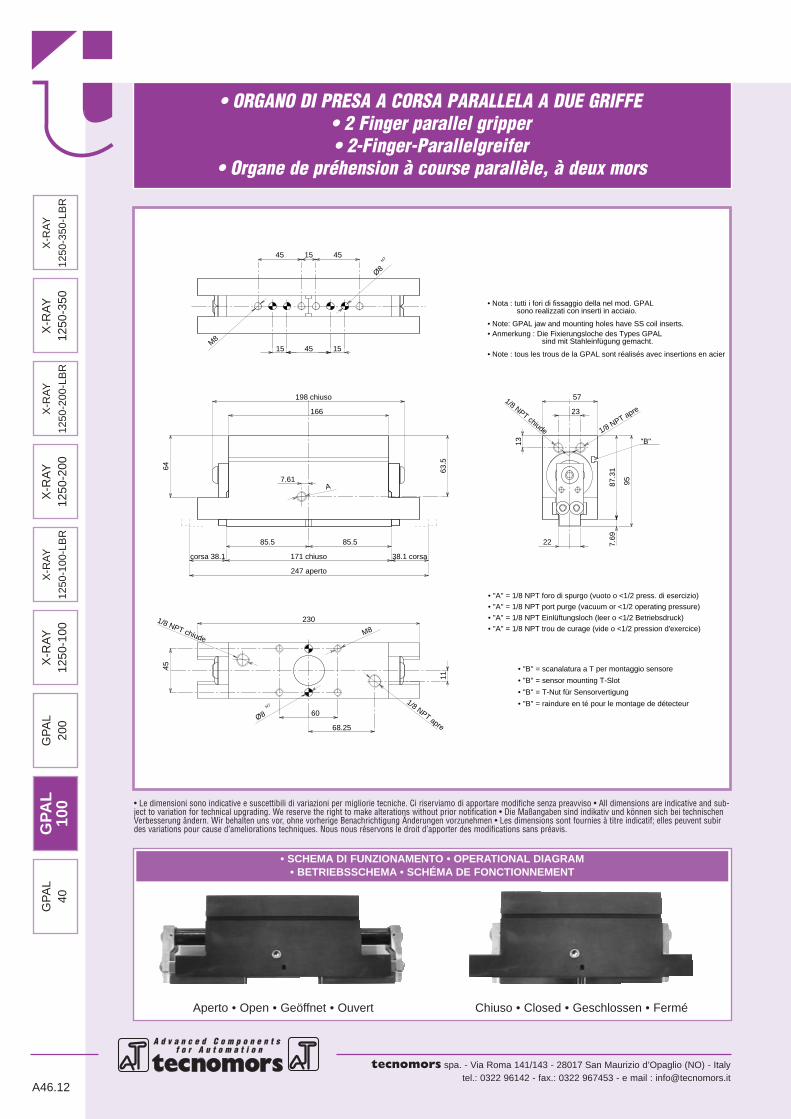
• ORGANO DI PRESA A CORSA PARALLELA A DUE GRIFFE• 2 Finger parallel gripper• 2-Finger-Parallelgreifer
• Organe de préhension à course parallèle, à deux mors
A d v a n c e d C o m p o n e n t s f o r A u t o m a t i o n
tecnomors spa. - Via Roma 141/143 - 28017 San Maurizio d’Opaglio (NO) - Italytel.: 0322 96142 - fax.: 0322 967453 - e mail : [email protected]
• Le dimensioni sono indicative e suscettibili di variazioni per migliorie tecniche. Ci riserviamo di apportare modifiche senza preavviso • All dimensions are indicative and sub-ject to variation for technical upgrading. We reserve the right to make alterations without prior notification • Die Maßangaben sind indikativ und können sich bei technischenVerbesserung ändern. Wir behalten uns vor, ohne vorherige Benachrichtigung Änderungen vorzunehmen • Les dimensions sont fournies à titre indicatif; elles peuvent subirdes variations pour cause d’ameliorations techniques. Nous nous réservons le droit d’apporter des modifications sans préavis.
• SCHEMA DI FUNZIONAMENTO • OPERATIONAL DIAGRAM• BETRIEBSSCHEMA • SCHÉMA DE FONCTIONNEMENT
Aperto • Open • Geöffnet • Ouvert Chiuso • Closed • Geschlossen • Fermé
1/8 NPT apre
• ''A'' = 10-32 UNF foro di spurgo (vuoto o <1/2 press. di esercizio)
1/8 NPT chiude
Ø8H7
1/8 NPT apre
• ''B'' = scanalatura a T per montaggio sensore
Ø8H7
1/8 NPT chiude
A
M8
M8
• ''A'' = 10-32 UNF port purge (vacuum or <1/2 operating pressure)
• ''A'' = 10-32 UNF Einlüftungsloch (leer o <1/2 Betriebsdruck)
• ''A'' = 10-32 UNF trou de curage (vide o <1/2 pression d'exercice)
"B"
• Note: GPAL jaw and mounting holes have SS coil inserts.• Anmerkung : Die Fixierungsloche des Types GPAL sind mit Stahleinfügung gemacht.
• Nota : tutti i fori di fissaggio della nel mod. GPAL sono realizzati con inserti in acciaio.
• Note : tous les trous de la GPAL sont réalisés avec insertions en acier
• ''B'' = sensor mounting T-Slot
• ''B'' = T-Nut für Sensorvertigung
• ''B'' = raindure en té pour le montage de détecteur
16.75
35
122 chiuso
146 chiuso
123
172.7 aperto
53.5
8.5
25.4 corsa
74.5
50
82
7.5
46
19
75
8.25
6161
corsa25.4
50
150
15
15
45 45
15 45
GPA
L40
X-R
AY
1250
-100
GP
AL
200
GP
AL
100
X-R
AY
1250
-100
-LB
R
X-R
AY
1250
-200
X-R
AY
1250
-200
-LB
R
X-R
AY
1250
-350
X-R
AY
1250
-350
-LB
R
A46.10
• ORGANO DI PRESA A CORSA PARALLELA A DUE GRIFFE• 2 Finger parallel gripper• 2-Finger-Parallelgreifer
• Organe de préhension à course parallèle, à deux mors
A d v a n c e d C o m p o n e n t s f o r A u t o m a t i o n f o r A u t o m a t i o n
tecnomors spa. - Via Roma 141/143 - 28017 San Maurizio d’Opaglio (NO) - Italytel.: 0322 96142 - fax.: 0322 967453 - e mail : [email protected]
A46.11
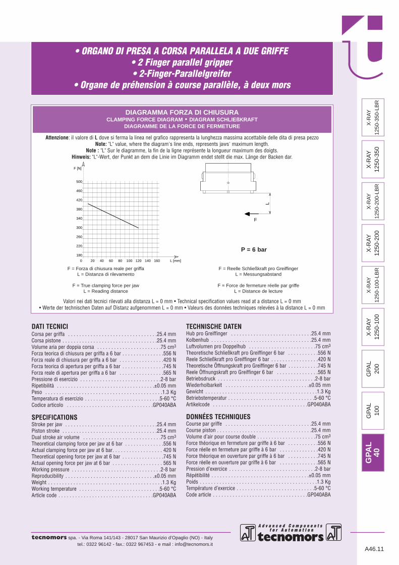
DATI TECNICICorsa per griffa . . . . . . . . . . . . . . . . . . . . . . . . . . . . . . . .25.4 mmCorsa pistone . . . . . . . . . . . . . . . . . . . . . . . . . . . . . . . . . .25.4 mmVolume aria per doppia corsa . . . . . . . . . . . . . . . . . . . . . . .75 cm3
Forza teorica di chiusura per griffa a 6 bar . . . . . . . . . . . . . . .556 NForza reale di chiusura per griffa a 6 bar . . . . . . . . . . . . . . . .420 NForza teorica di apertura per griffa a 6 bar . . . . . . . . . . . . . . .745 NForza reale di apertura per griffa a 6 bar . . . . . . . . . . . . . . . .565 NPressione di esercizio . . . . . . . . . . . . . . . . . . . . . . . . . . . . .2-8 barRipetibilità . . . . . . . . . . . . . . . . . . . . . . . . . . . . . . . . . . .±0.05 mmPeso . . . . . . . . . . . . . . . . . . . . . . . . . . . . . . . . . . . . . . . . . .1.3 KgTemperatura di esercizio . . . . . . . . . . . . . . . . . . . . . . . . . . .5-60 °CCodice articolo . . . . . . . . . . . . . . . . . . . . . . . . . . . . . . .GP040ABA
SPECIFICATIONSStroke per jaw . . . . . . . . . . . . . . . . . . . . . . . . . . . . . . . . .25.4 mmPiston stroke . . . . . . . . . . . . . . . . . . . . . . . . . . . . . . . . . .25.4 mmDual stroke air volume . . . . . . . . . . . . . . . . . . . . . . . . . . . .75 cm3
Theoretical clamping force per jaw at 6 bar . . . . . . . . . . . . . .556 NActual clamping force per jaw at 6 bar. . . . . . . . . . . . . . . . . . 420 NTheoretical opening force per jaw at 6 bar . . . . . . . . . . . . . . .745 NActual opening force per jaw at 6 bar . . . . . . . . . . . . . . . . . . 565 NWorking pressure . . . . . . . . . . . . . . . . . . . . . . . . . . . . . . . .2-8 barReproducibility . . . . . . . . . . . . . . . . . . . . . . . . . . . . . . . .±0.05 mmWeight . . . . . . . . . . . . . . . . . . . . . . . . . . . . . . . . . . . . . . . . .1.3 KgWorking temperature . . . . . . . . . . . . . . . . . . . . . . . . . . . . .5-60 °CArticle code . . . . . . . . . . . . . . . . . . . . . . . . . . . . . . . . . .GP040ABA
TECHNISCHE DATENHub pro Greiffinger . . . . . . . . . . . . . . . . . . . . . . . . . . . . .25.4 mmKolbenhub . . . . . . . . . . . . . . . . . . . . . . . . . . . . . . . . . . . .25.4 mmLuftvolumen pro Doppelhub . . . . . . . . . . . . . . . . . . . . . . . .75 cm3
Theoretische Schließkraft pro Greiffinger 6 bar . . . . . . . . . . .556 NReele Schließkraft pro Greiffinger 6 bar . . . . . . . . . . . . . . . . .420 NTheoretische Öffnungskraft pro Greiffinger 6 bar . . . . . . . . . . .745 NReele Öffnungskraft pro Greiffinger 6 bar . . . . . . . . . . . . . . .565 NBetriebsdruck . . . . . . . . . . . . . . . . . . . . . . . . . . . . . . . . . . .2-8 barWiederholbarkeit . . . . . . . . . . . . . . . . . . . . . . . . . . . . . .±0.05 mmGewicht . . . . . . . . . . . . . . . . . . . . . . . . . . . . . . . . . . . . . . . .1.3 KgBetriebstemperatur . . . . . . . . . . . . . . . . . . . . . . . . . . . . . . .5-60 °CArtikelcode . . . . . . . . . . . . . . . . . . . . . . . . . . . . . . . . . .GP040ABA
DONNÉES TECHNIQUESCourse par griffe . . . . . . . . . . . . . . . . . . . . . . . . . . . . . . .25.4 mmCourse piston . . . . . . . . . . . . . . . . . . . . . . . . . . . . . . . . . .25.4 mmVolume d’air pour course double . . . . . . . . . . . . . . . . . . . . .75 cm3
Force théorique en fermeture par griffe à 6 bar . . . . . . . . . . .556 NForce réelle en fermeture par griffe à 6 bar . . . . . . . . . . . . . .420 NForce théorique en ouverture par griffe à 6 bar . . . . . . . . . . .745 NForce réelle en ouverture par griffe à 6 bar . . . . . . . . . . . . . .565 NPression d’exercice . . . . . . . . . . . . . . . . . . . . . . . . . . . . . . .2-8 barRépétibilité . . . . . . . . . . . . . . . . . . . . . . . . . . . . . . . . . . .±0.05 mmPoids . . . . . . . . . . . . . . . . . . . . . . . . . . . . . . . . . . . . . . . . . .1.3 KgTempérature d’exercice . . . . . . . . . . . . . . . . . . . . . . . . . . . .5-60 °CCode article . . . . . . . . . . . . . . . . . . . . . . . . . . . . . . . . . .GP040ABA
L [mm]
220
460
500
F [N]
300
16020 40 60 1000 80
260
180
340
380
120 140
420
F
L
DIAGRAMMA FORZA DI CHIUSURACLAMPING FORCE DIAGRAM • DIAGRAM SCHLIEßKRAFT
DIAGRAMME DE LA FORCE DE FERMETURE
Valori nei dati tecnici rilevati alla distanza L = 0 mm • Technical specification values read at a distance L = 0 mm• Werte der technischen Daten auf Distanz aufgenommen L = 0 mm • Valeurs des données techniques relevées à la distance L = 0 mm
F = Forza di chiusura reale per griffaL = Distanza di rilevamento
F = True clamping force per jawL = Reading distance
F = Reelle Schließkraft pro GreiffingerL = Messungsabstand
F = Force de fermeture réelle par griffeL = Distance de lecture
P = 6 bar
Attenzione: il valore di L dove si ferma la linea nel grafico rappresenta la lunghezza massima accettabile delle dita di presa pezzoNote: "L" value, where the diagram's line ends, represents jaws' maximum length.
Note : "L" Sur le diagramme, la fin de la ligne représente la longueur maximum des doigts.Hinweis: "L"-Wert, der Punkt an dem die Linie im Diagramm endet stellt die max. Länge der Backen dar.
GPA
L40
X-R
AY
1250
-100
GP
AL
200
GP
AL
100
X-R
AY
1250
-100
-LB
R
X-R
AY
1250
-200
X-R
AY
1250
-200
-LB
R
X-R
AY
1250
-350
X-R
AY
1250
-350
-LB
R
• ORGANO DI PRESA A CORSA PARALLELA A DUE GRIFFE• 2 Finger parallel gripper• 2-Finger-Parallelgreifer
• Organe de préhension à course parallèle, à deux mors
A d v a n c e d C o m p o n e n t s f o r A u t o m a t i o n
tecnomors spa. - Via Roma 141/143 - 28017 San Maurizio d’Opaglio (NO) - Italytel.: 0322 96142 - fax.: 0322 967453 - e mail : [email protected]
• Le dimensioni sono indicative e suscettibili di variazioni per migliorie tecniche. Ci riserviamo di apportare modifiche senza preavviso • All dimensions are indicative and sub-ject to variation for technical upgrading. We reserve the right to make alterations without prior notification • Die Maßangaben sind indikativ und können sich bei technischenVerbesserung ändern. Wir behalten uns vor, ohne vorherige Benachrichtigung Änderungen vorzunehmen • Les dimensions sont fournies à titre indicatif; elles peuvent subirdes variations pour cause d’ameliorations techniques. Nous nous réservons le droit d’apporter des modifications sans préavis.
• SCHEMA DI FUNZIONAMENTO • OPERATIONAL DIAGRAM• BETRIEBSSCHEMA • SCHÉMA DE FONCTIONNEMENT
Aperto • Open • Geöffnet • Ouvert Chiuso • Closed • Geschlossen • Fermé
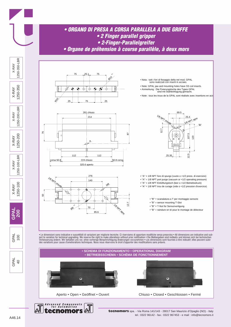
• ''A'' = 1/8 NPT foro di spurgo (vuoto o <1/2 press. di esercizio)
• ''A'' = 1/8 NPT port purge (vacuum or <1/2 operating pressure)
• ''A'' = 1/8 NPT Einlüftungsloch (leer o <1/2 Betriebsdruck)
• ''A'' = 1/8 NPT trou de curage (vide o <1/2 pression d'exercice)
• ''B'' = scanalatura a T per montaggio sensore
7.61A
1/8 NPT apre1/8 NPT chiude
M8
M8
1/8 NPT apre
1/8 NPT chiude
"B"
• ''B'' = sensor mounting T-Slot
• ''B'' = T-Nut für Sensorvertigung
• ''B'' = raindure en té pour le montage de détecteur
Ø8H7
• Note: GPAL jaw and mounting holes have SS coil inserts.• Anmerkung : Die Fixierungsloche des Types GPAL sind mit Stahleinfügung gemacht.
• Nota : tutti i fori di fissaggio della nel mod. GPAL sono realizzati con inserti in acciaio.
• Note : tous les trous de la GPAL sont réalisés avec insertions en acier
Ø8H7
85.5 22
13
23
57
85.5
198 chiuso
166
95
38.1 corsa171 chiuso
247 aperto
7.69
63.5
87.3
1
corsa 38.1
64
45
15 45 15
45 15
11
45
68.25
230
60
GPA
L10
0X
-RA
Y12
50-1
00G
PA
L20
0G
PA
L40
X-R
AY
1250
-100
-LB
R
X-R
AY
1250
-200
X-R
AY
1250
-200
-LB
R
X-R
AY
1250
-350
X-R
AY
1250
-350
-LB
R
A46.12

• ORGANO DI PRESA A CORSA PARALLELA A DUE GRIFFE• 2 Finger parallel gripper• 2-Finger-Parallelgreifer
• Organe de préhension à course parallèle, à deux mors
A d v a n c e d C o m p o n e n t s f o r A u t o m a t i o n f o r A u t o m a t i o n
tecnomors spa. - Via Roma 141/143 - 28017 San Maurizio d’Opaglio (NO) - Italytel.: 0322 96142 - fax.: 0322 967453 - e mail : [email protected]
A46.13
DATI TECNICICorsa per griffa . . . . . . . . . . . . . . . . . . . . . . . . . . . . . . . .38.1 mmCorsa pistone . . . . . . . . . . . . . . . . . . . . . . . . . . . . . . . . . .38.1 mmVolume aria per doppia corsa . . . . . . . . . . . . . . . . . . . . . .235 cm3
Forza teorica di chiusura per griffa a 6 bar . . . . . . . . . . . . . . .820 NForza reale di chiusura per griffa a 6 bar . . . . . . . . . . . . . . . .620 NForza teorica di apertura per griffa a 6 bar . . . . . . . . . . . . . . .970 NForza reale di apertura per griffa a 6 bar . . . . . . . . . . . . . . . .735 NPressione di esercizio . . . . . . . . . . . . . . . . . . . . . . . . . . . . .2-8 barRipetibilità . . . . . . . . . . . . . . . . . . . . . . . . . . . . . . . . . . .±0.05 mmPeso . . . . . . . . . . . . . . . . . . . . . . . . . . . . . . . . . . . . . . . . . .2.4 KgTemperatura di esercizio . . . . . . . . . . . . . . . . . . . . . . . . . . .5-60 °CCodice articolo . . . . . . . . . . . . . . . . . . . . . . . . . . . . . . .GP100ABB
SPECIFICATIONSStroke per jaw . . . . . . . . . . . . . . . . . . . . . . . . . . . . . . . . .38.1 mmPiston stroke . . . . . . . . . . . . . . . . . . . . . . . . . . . . . . . . . .38.1 mmDual stroke air volume . . . . . . . . . . . . . . . . . . . . . . . . . . .235 cm3
Theoretical clamping force per jaw at 6 bar . . . . . . . . . . . . . .820 NActual clamping force per jaw at 6 bar. . . . . . . . . . . . . . . . . . 620 NTheoretical opening force per jaw at 6 bar . . . . . . . . . . . . . . .970 NActual opening force per jaw at 6 bar . . . . . . . . . . . . . . . . . . 735 NWorking pressure . . . . . . . . . . . . . . . . . . . . . . . . . . . . . . . .2-8 barReproducibility . . . . . . . . . . . . . . . . . . . . . . . . . . . . . . . .±0.05 mmWeight . . . . . . . . . . . . . . . . . . . . . . . . . . . . . . . . . . . . . . . . .2.4 KgWorking temperature . . . . . . . . . . . . . . . . . . . . . . . . . . . . .5-60 °CArticle code . . . . . . . . . . . . . . . . . . . . . . . . . . . . . . . . . .GP100ABB
TECHNISCHE DATENHub pro Greiffinger . . . . . . . . . . . . . . . . . . . . . . . . . . . . .38.1 mmKolbenhub . . . . . . . . . . . . . . . . . . . . . . . . . . . . . . . . . . . .38.1 mmLuftvolumen pro Doppelhub . . . . . . . . . . . . . . . . . . . . . . .235 cm3
Theoretische Schließkraft pro Greiffinger 6 bar . . . . . . . . . . .820 NReele Schließkraft pro Greiffinger 6 bar . . . . . . . . . . . . . . . . .620 NTheoretische Öffnungskraft pro Greiffinger 6 bar . . . . . . . . . . .970 NReele Öffnungskraft pro Greiffinger 6 bar . . . . . . . . . . . . . . .735 NBetriebsdruck . . . . . . . . . . . . . . . . . . . . . . . . . . . . . . . . . . .2-8 barWiederholbarkeit . . . . . . . . . . . . . . . . . . . . . . . . . . . . . .±0.05 mmGewicht . . . . . . . . . . . . . . . . . . . . . . . . . . . . . . . . . . . . . . . .2.4 KgBetriebstemperatur . . . . . . . . . . . . . . . . . . . . . . . . . . . . . . .5-60 °CArtikelcode . . . . . . . . . . . . . . . . . . . . . . . . . . . . . . . . . .GP100ABB
DONNÉES TECHNIQUESCourse par griffe . . . . . . . . . . . . . . . . . . . . . . . . . . . . . . .38.1 mmCourse piston . . . . . . . . . . . . . . . . . . . . . . . . . . . . . . . . . .38.1 mmVolume d’air pour course double . . . . . . . . . . . . . . . . . . . .235 cm3
Force théorique en fermeture par griffe à 6 bar . . . . . . . . . . .820 NForce réelle en fermeture par griffe à 6 bar . . . . . . . . . . . . . .620 NForce théorique en ouverture par griffe à 6 bar . . . . . . . . . . .970 NForce réelle en ouverture par griffe à 6 bar . . . . . . . . . . . . . .735 NPression d’exercice . . . . . . . . . . . . . . . . . . . . . . . . . . . . . . .2-8 barRépétibilité . . . . . . . . . . . . . . . . . . . . . . . . . . . . . . . . . . .±0.05 mmPoids . . . . . . . . . . . . . . . . . . . . . . . . . . . . . . . . . . . . . . . . . .2.4 KgTempérature d’exercice . . . . . . . . . . . . . . . . . . . . . . . . . . . .5-60 °CCode article . . . . . . . . . . . . . . . . . . . . . . . . . . . . . . . . . .GP100ABB
380
420
460
L [mm]
500
660
540
580
620
340
F
F [N]
16020 40 60 1000 80 120 140
L
DIAGRAMMA FORZA DI CHIUSURACLAMPING FORCE DIAGRAM • DIAGRAM SCHLIEßKRAFT
DIAGRAMME DE LA FORCE DE FERMETURE
Valori nei dati tecnici rilevati alla distanza L = 0 mm • Technical specification values read at a distance L = 0 mm• Werte der technischen Daten auf Distanz aufgenommen L = 0 mm • Valeurs des données techniques relevées à la distance L = 0 mm
F = Forza di chiusura reale per griffaL = Distanza di rilevamento
F = True clamping force per jawL = Reading distance
F = Reelle Schließkraft pro GreiffingerL = Messungsabstand
F = Force de fermeture réelle par griffeL = Distance de lecture
P = 6 bar
Attenzione: il valore di L dove si ferma la linea nel grafico rappresenta la lunghezza massima accettabile delle dita di presa pezzoNote: "L" value, where the diagram's line ends, represents jaws' maximum length.
Note : "L" Sur le diagramme, la fin de la ligne représente la longueur maximum des doigts.Hinweis: "L"-Wert, der Punkt an dem die Linie im Diagramm endet stellt die max. Länge der Backen dar.
X-R
AY
1250
-100
GP
AL
200
X-R
AY
1250
-100
-LB
R
X-R
AY
1250
-200
X-R
AY
1250
-200
-LB
R
X-R
AY
1250
-350
X-R
AY
1250
-350
-LB
RG
PAL
100
GP
AL
40
• ORGANO DI PRESA A CORSA PARALLELA A DUE GRIFFE• 2 Finger parallel gripper• 2-Finger-Parallelgreifer
• Organe de préhension à course parallèle, à deux mors
A d v a n c e d C o m p o n e n t s f o r A u t o m a t i o n
tecnomors spa. - Via Roma 141/143 - 28017 San Maurizio d’Opaglio (NO) - Italytel.: 0322 96142 - fax.: 0322 967453 - e mail : [email protected]
• Le dimensioni sono indicative e suscettibili di variazioni per migliorie tecniche. Ci riserviamo di apportare modifiche senza preavviso • All dimensions are indicative and sub-ject to variation for technical upgrading. We reserve the right to make alterations without prior notification • Die Maßangaben sind indikativ und können sich bei technischenVerbesserung ändern. Wir behalten uns vor, ohne vorherige Benachrichtigung Änderungen vorzunehmen • Les dimensions sont fournies à titre indicatif; elles peuvent subirdes variations pour cause d’ameliorations techniques. Nous nous réservons le droit d’apporter des modifications sans préavis.
• SCHEMA DI FUNZIONAMENTO • OPERATIONAL DIAGRAM• BETRIEBSSCHEMA • SCHÉMA DE FONCTIONNEMENT
Aperto • Open • Geöffnet • Ouvert Chiuso • Closed • Geschlossen • Fermé
• ''A'' = 1/8 NPT trou de curage (vide o <1/2 pression d'exercice)
• ''A'' = 1/8 NPT Einlüftungsloch (leer o <1/2 Betriebsdruck)
1/8 NPT chiude
1/8 NPT apre
M8
A
1/8 NPT apre1/8 NPT chiude
M10
• ''B'' = scanalatura a T per montaggio sensore
• ''B'' = sensor mounting T-Slot
• ''B'' = T-Nut für Sensorvertigung
• ''B'' = raindure en té pour le montage de détecteur
"B"
• Note: GPAL jaw and mounting holes have SS coil inserts.• Anmerkung : Die Fixierungsloche des Types GPAL sind mit Stahleinfügung gemacht.
• Nota : tutti i fori di fissaggio della nel mod. GPAL sono realizzati con inserti in acciaio.
• Note : tous les trous de la GPAL sont réalisés avec insertions en acie
Ø8H7
Ø10H7
• ''A'' = 1/8 NPT foro di spurgo (vuoto o <1/2 press. di esercizio)
• ''A'' = 1/8 NPT port purge (vacuum or <1/2 operating pressure)
87
70
12.7
85.6
50.8 corsa
140
112 112
224 chiuso
325.6 aperto
276
corsa 50.8
214
76
12.5
12.7
25.35
25.4
69.5
120
107.
5
261 chiuso
25 25
25.1
75
75 75
50
GPA
L20
0X
-RA
Y12
50-1
00G
PA
L10
0G
PA
L40
X-R
AY
1250
-100
-LB
R
X-R
AY
1250
-200
X-R
AY
1250
-200
-LB
R
X-R
AY
1250
-350
X-R
AY
1250
-350
-LB
R
A46.14

• ORGANO DI PRESA A CORSA PARALLELA A DUE GRIFFE• 2 Finger parallel gripper• 2-Finger-Parallelgreifer
• Organe de préhension à course parallèle, à deux mors
A d v a n c e d C o m p o n e n t s f o r A u t o m a t i o n f o r A u t o m a t i o n
tecnomors spa. - Via Roma 141/143 - 28017 San Maurizio d’Opaglio (NO) - Italytel.: 0322 96142 - fax.: 0322 967453 - e mail : [email protected]
A46.15
DATI TECNICICorsa per griffa . . . . . . . . . . . . . . . . . . . . . . . . . . . . . . . .50.8 mmCorsa pistone . . . . . . . . . . . . . . . . . . . . . . . . . . . . . . . . . .50.8 mmVolume aria per doppia corsa . . . . . . . . . . . . . . . . . . . . . .590 cm3
Forza teorica di chiusura per griffa a 6 bar . . . . . . . . . . . . . .1500 NForza reale di chiusura per griffa a 6 bar . . . . . . . . . . . . . . .1150 NForza teorica di apertura per griffa a 6 bar . . . . . . . . . . . . . .1830 NForza reale di apertura per griffa a 6 bar . . . . . . . . . . . . . . .1390 NPressione di esercizio . . . . . . . . . . . . . . . . . . . . . . . . . . . . .2-8 barRipetibilità . . . . . . . . . . . . . . . . . . . . . . . . . . . . . . . . . . .±0.05 mmPeso . . . . . . . . . . . . . . . . . . . . . . . . . . . . . . . . . . . . . . . . . .4.4 KgTemperatura di esercizio . . . . . . . . . . . . . . . . . . . . . . . . . . .5-60 °CCodice articolo . . . . . . . . . . . . . . . . . . . . . . . . . . . . . . .GP200ABC
SPECIFICATIONSStroke per jaw . . . . . . . . . . . . . . . . . . . . . . . . . . . . . . . . .50.8 mmPiston stroke . . . . . . . . . . . . . . . . . . . . . . . . . . . . . . . . . .50.8 mmDual stroke air volume . . . . . . . . . . . . . . . . . . . . . . . . . . .590 cm3
Theoretical clamping force per jaw at 6 bar . . . . . . . . . . . . .1500 NActual clamping force per jaw at 6 bar. . . . . . . . . . . . . . . . . 1150 NTheoretical opening force per jaw at 6 bar . . . . . . . . . . . . . .1830 NActual opening force per jaw at 6 bar . . . . . . . . . . . . . . . . . 1390 NWorking pressure . . . . . . . . . . . . . . . . . . . . . . . . . . . . . . . .2-8 barReproducibility . . . . . . . . . . . . . . . . . . . . . . . . . . . . . . . .±0.05 mmWeight . . . . . . . . . . . . . . . . . . . . . . . . . . . . . . . . . . . . . . . . .4.4 KgWorking temperature . . . . . . . . . . . . . . . . . . . . . . . . . . . . .5-60 °CArticle code . . . . . . . . . . . . . . . . . . . . . . . . . . . . . . . . . .GP200ABC
TECHNISCHE DATENHub pro Greiffinger . . . . . . . . . . . . . . . . . . . . . . . . . . . . .50.8 mmKolbenhub . . . . . . . . . . . . . . . . . . . . . . . . . . . . . . . . . . . .50.8 mmLuftvolumen pro Doppelhub . . . . . . . . . . . . . . . . . . . . . . .590 cm3
Theoretische Schließkraft pro Greiffinger 6 bar . . . . . . . . . .1500 NReele Schließkraft pro Greiffinger 6 bar . . . . . . . . . . . . . . . .1150 NTheoretische Öffnungskraft pro Greiffinger 6 bar . . . . . . . . . .1830 NReele Öffnungskraft pro Greiffinger 6 bar . . . . . . . . . . . . . .1390 NBetriebsdruck . . . . . . . . . . . . . . . . . . . . . . . . . . . . . . . . . . .2-8 barWiederholbarkeit . . . . . . . . . . . . . . . . . . . . . . . . . . . . . .±0.05 mmGewicht . . . . . . . . . . . . . . . . . . . . . . . . . . . . . . . . . . . . . . . .4.4 KgBetriebstemperatur . . . . . . . . . . . . . . . . . . . . . . . . . . . . . . .5-60 °CArtikelcode . . . . . . . . . . . . . . . . . . . . . . . . . . . . . . . . . .GP200ABC
DONNÉES TECHNIQUESCourse par griffe . . . . . . . . . . . . . . . . . . . . . . . . . . . . . . .50.8 mmCourse piston . . . . . . . . . . . . . . . . . . . . . . . . . . . . . . . . . .50.8 mmVolume d’air pour course double . . . . . . . . . . . . . . . . . . . .590 cm3
Force théorique en fermeture par griffe à 6 bar . . . . . . . . . .1500 NForce réelle en fermeture par griffe à 6 bar . . . . . . . . . . . . .1150 NForce théorique en ouverture par griffe à 6 bar . . . . . . . . . .1830 NForce réelle en ouverture par griffe à 6 bar . . . . . . . . . . . . .1390 NPression d’exercice . . . . . . . . . . . . . . . . . . . . . . . . . . . . . . .2-8 barRépétibilité . . . . . . . . . . . . . . . . . . . . . . . . . . . . . . . . . . .±0.05 mmPoids . . . . . . . . . . . . . . . . . . . . . . . . . . . . . . . . . . . . . . . . . .4.4 KgTempérature d’exercice . . . . . . . . . . . . . . . . . . . . . . . . . . . .5-60 °CCode article . . . . . . . . . . . . . . . . . . . . . . . . . . . . . . . . . .GP200ABC
L [mm]
220
460
500
F [N]
300
16020 40 60 1000 80
260
180
340
380
120 140
420
F
L
DIAGRAMMA FORZA DI CHIUSURACLAMPING FORCE DIAGRAM • DIAGRAM SCHLIEßKRAFT
DIAGRAMME DE LA FORCE DE FERMETURE
Valori nei dati tecnici rilevati alla distanza L = 0 mm • Technical specification values read at a distance L = 0 mm• Werte der technischen Daten auf Distanz aufgenommen L = 0 mm • Valeurs des données techniques relevées à la distance L = 0 mm
F = Forza di chiusura reale per griffaL = Distanza di rilevamento
F = True clamping force per jawL = Reading distance
F = Reelle Schließkraft pro GreiffingerL = Messungsabstand
F = Force de fermeture réelle par griffeL = Distance de lecture
P = 6 bar
Attenzione: il valore di L dove si ferma la linea nel grafico rappresenta la lunghezza massima accettabile delle dita di presa pezzoNote: "L" value, where the diagram's line ends, represents jaws' maximum length.
Note : "L" Sur le diagramme, la fin de la ligne représente la longueur maximum des doigts.Hinweis: "L"-Wert, der Punkt an dem die Linie im Diagramm endet stellt die max. Länge der Backen dar.
X-R
AY
1250
-100
X-R
AY
1250
-100
-LB
R
X-R
AY
1250
-200
X-R
AY
1250
-200
-LB
R
X-R
AY
1250
-350
X-R
AY
1250
-350
-LB
RG
PAL
200
GP
AL
100
GP
AL
40
• ORGANO DI PRESA A CORSA PARALLELA A DUE GRIFFE• 2 Finger parallel gripper• 2-Finger-Parallelgreifer
• Organe de préhension à course parallèle, à deux mors
A d v a n c e d C o m p o n e n t s f o r A u t o m a t i o n
tecnomors spa. - Via Roma 141/143 - 28017 San Maurizio d’Opaglio (NO) - Italytel.: 0322 96142 - fax.: 0322 967453 - e mail : [email protected]
• Le dimensioni sono indicative e suscettibili di variazioni per migliorie tecniche. Ci riserviamo di apportare modifiche senza preavviso • All dimensions are indicative and sub-ject to variation for technical upgrading. We reserve the right to make alterations without prior notification • Die Maßangaben sind indikativ und können sich bei technischenVerbesserung ändern. Wir behalten uns vor, ohne vorherige Benachrichtigung Änderungen vorzunehmen • Les dimensions sont fournies à titre indicatif; elles peuvent subirdes variations pour cause d’ameliorations techniques. Nous nous réservons le droit d’apporter des modifications sans préavis.
A46.16
• SCHEMA DI FUNZIONAMENTO • OPERATIONAL DIAGRAM• BETRIEBSSCHEMA • SCHÉMA DE FONCTIONNEMENT
Aperto • Open • Geöffnet • Ouvert Chiuso • Closed • Geschlossen • Fermé
X-R
AY12
50-1
00X
-RA
Y12
50-2
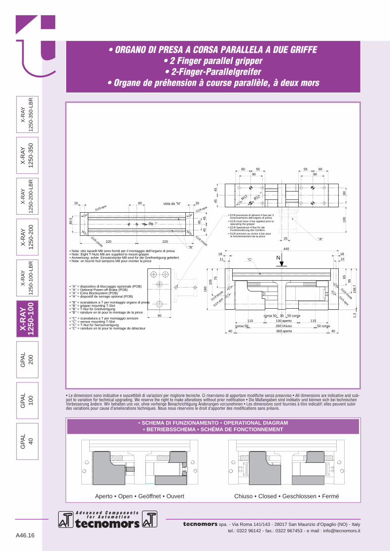
00 • G1/8 Speisdruck 4 Bar für die Funktionnierung des Greifers
G1/4 chiude
• Nota: otto tasselli M8 sono forniti per il montaggio dell'organo di presa• Note: Eight T-Nuts M8 are supplied to mount gripper.• Anmerkung: achte Einsatzstücke M8 sind für die Greifvertigung geliefert.• Note: on fournit huit tampons M8 pour monter la pince
''B''
G1/8 apre
• ''A'' = dispositif de serrage optional (POB)
• ''C'' = raindure en té pour le montage de détecteur
N
• G1/8 pression au moins 4 bar pour le fonctionnement de la pince
• ''B'' = raindure en té pour le montage de la pince
• G1/8 must have 4 bar applied prior to operating the gripper
• G1/8 pressione di almeno 4 bar per il funzionamento dell'organo di presa.
vista da ''N''
G1/4 apre
G1/8 apre
G1/8 chiude
G1/8 chiude
G1/4 chiudeG1/4 apre
M12
''C''
''A''
• ''B'' = scanalature a T per montaggio organo di presa
• ''C'' = scanalatura a T per montaggio sensore• ''C'' = sensor mounting T-Slot
• ''A'' = Extra Blocksystem (POB)• ''A'' = Optional Power-off Brake (POB)
• ''B'' = gripper mounting T-Slot• ''B'' = T-Nut für Greifvertigung
• ''C'' = T-Nut für Sensorvertigung
• ''A'' = dispositivo di bloccaggio opzionale (POB)
Ø8 H7
Ø12H7
10
16
18
11
16
18
25
160
130 aperto
105
corsa 50
115 115
360 aperto 40
95
65
40
75
1.3
50 corsa
158.
7
440
220220
60
66.5
45
corsa 50 30
260 chiuso
50 corsa
90 90
6010
0
605560 55
4545
4545
90
GP
AL
100
GP
AL
40G
PA
L20
0X
-RA
Y
1250
-200
-LB
R
X-R
AY
1250
-100
-LB
R
X-R
AY
1250
-350
X-R
AY
1250
-350
-LB
R

• ORGANO DI PRESA A CORSA PARALLELA A DUE GRIFFE• 2 Finger parallel gripper• 2-Finger-Parallelgreifer
• Organe de préhension à course parallèle, à deux mors
A d v a n c e d C o m p o n e n t s f o r A u t o m a t i o n f o r A u t o m a t i o n
tecnomors spa. - Via Roma 141/143 - 28017 San Maurizio d’Opaglio (NO) - Italytel.: 0322 96142 - fax.: 0322 967453 - e mail : [email protected]
A46.17
DATI TECNICICorsa per griffa . . . . . . . . . . . . . . . . . . . . . . . . . . . . . . . . . .50 mmCorsa pistone . . . . . . . . . . . . . . . . . . . . . . . . . . . . . . . . . . .50 mmVolume aria per doppia corsa . . . . . . . . . . . . . . . . . . . . . .373 cm3
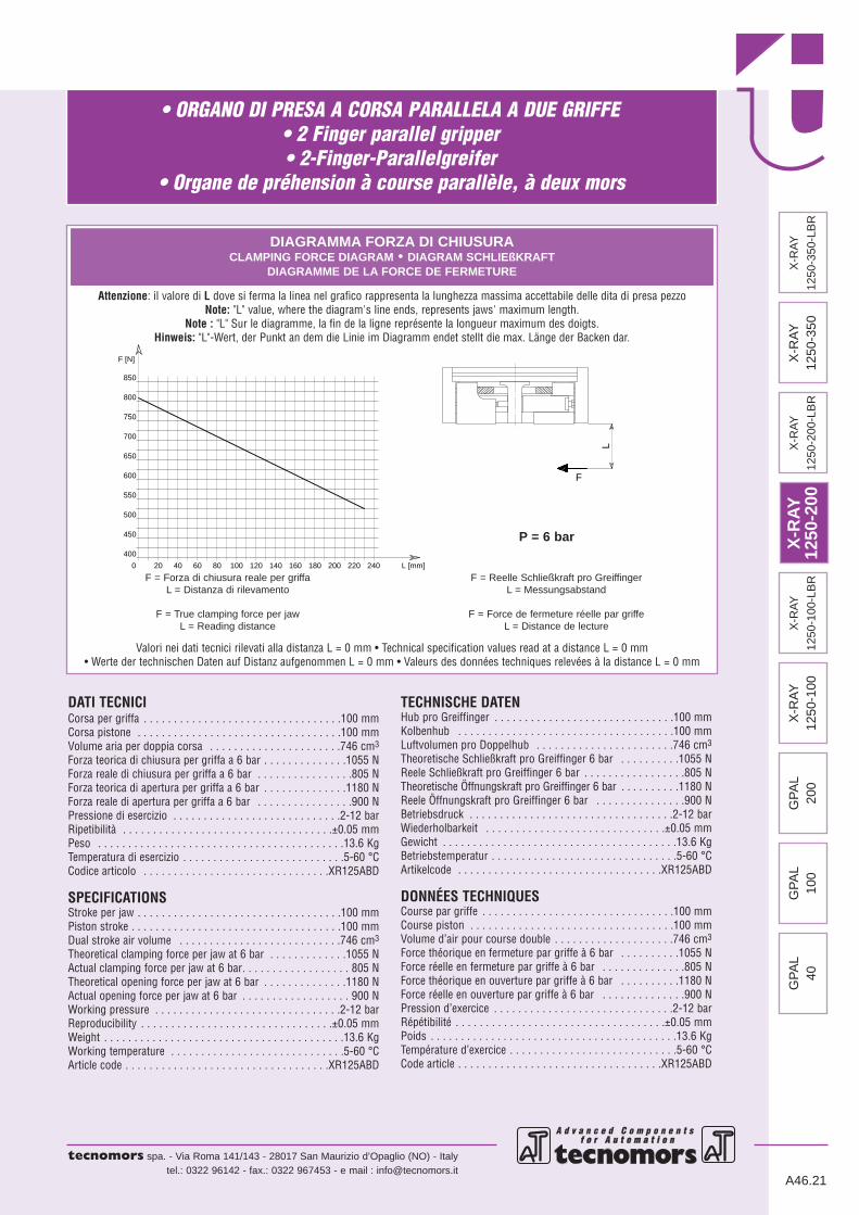
Forza teorica di chiusura per griffa a 6 bar . . . . . . . . . . . . . .1055 NForza reale di chiusura per griffa a 6 bar . . . . . . . . . . . . . . . .805 NForza teorica di apertura per griffa a 6 bar . . . . . . . . . . . . . .1180 NForza reale di apertura per griffa a 6 bar . . . . . . . . . . . . . . . .900 NPressione di esercizio . . . . . . . . . . . . . . . . . . . . . . . . . . . .2-12 barRipetibilità . . . . . . . . . . . . . . . . . . . . . . . . . . . . . . . . . . .±0.05 mmPeso . . . . . . . . . . . . . . . . . . . . . . . . . . . . . . . . . . . . . . . . .12.7 KgTemperatura di esercizio . . . . . . . . . . . . . . . . . . . . . . . . . . .5-60 °CCodice articolo . . . . . . . . . . . . . . . . . . . . . . . . . . . . . . .XR125ABC
SPECIFICATIONSStroke per jaw . . . . . . . . . . . . . . . . . . . . . . . . . . . . . . . . . . .50 mmPiston stroke . . . . . . . . . . . . . . . . . . . . . . . . . . . . . . . . . . .50 mmDual stroke air volume . . . . . . . . . . . . . . . . . . . . . . . . . . .373 cm3
Theoretical clamping force per jaw at 6 bar . . . . . . . . . . . . .1055 NActual clamping force per jaw at 6 bar. . . . . . . . . . . . . . . . . . 805 NTheoretical opening force per jaw at 6 bar . . . . . . . . . . . . . .1180 NActual opening force per jaw at 6 bar . . . . . . . . . . . . . . . . . . 900 NWorking pressure . . . . . . . . . . . . . . . . . . . . . . . . . . . . . . .2-12 barReproducibility . . . . . . . . . . . . . . . . . . . . . . . . . . . . . . . .±0.05 mmWeight . . . . . . . . . . . . . . . . . . . . . . . . . . . . . . . . . . . . . . . .12.7 KgWorking temperature . . . . . . . . . . . . . . . . . . . . . . . . . . . . .5-60 °CArticle code . . . . . . . . . . . . . . . . . . . . . . . . . . . . . . . . . .XR125ABC
TECHNISCHE DATENHub pro Greiffinger . . . . . . . . . . . . . . . . . . . . . . . . . . . . . . .50 mmKolbenhub . . . . . . . . . . . . . . . . . . . . . . . . . . . . . . . . . . . . .50 mmLuftvolumen pro Doppelhub . . . . . . . . . . . . . . . . . . . . . . .373 cm3
Theoretische Schließkraft pro Greiffinger 6 bar . . . . . . . . . .1055 NReele Schließkraft pro Greiffinger 6 bar . . . . . . . . . . . . . . . . .805 NTheoretische Öffnungskraft pro Greiffinger 6 bar . . . . . . . . . .1180 NReele Öffnungskraft pro Greiffinger 6 bar . . . . . . . . . . . . . . .900 NBetriebsdruck . . . . . . . . . . . . . . . . . . . . . . . . . . . . . . . . . .2-12 barWiederholbarkeit . . . . . . . . . . . . . . . . . . . . . . . . . . . . . .±0.05 mmGewicht . . . . . . . . . . . . . . . . . . . . . . . . . . . . . . . . . . . . . . .12.7 KgBetriebstemperatur . . . . . . . . . . . . . . . . . . . . . . . . . . . . . . .5-60 °CArtikelcode . . . . . . . . . . . . . . . . . . . . . . . . . . . . . . . . . .XR125ABC
DONNÉES TECHNIQUESCourse par griffe . . . . . . . . . . . . . . . . . . . . . . . . . . . . . . . . .50 mmCourse piston . . . . . . . . . . . . . . . . . . . . . . . . . . . . . . . . . . .50 mmVolume d’air pour course double . . . . . . . . . . . . . . . . . . . .373 cm3
Force théorique en fermeture par griffe à 6 bar . . . . . . . . . .1055 NForce réelle en fermeture par griffe à 6 bar . . . . . . . . . . . . . .805 NForce théorique en ouverture par griffe à 6 bar . . . . . . . . . .1180 NForce réelle en ouverture par griffe à 6 bar . . . . . . . . . . . . . .900 NPression d’exercice . . . . . . . . . . . . . . . . . . . . . . . . . . . . . .2-12 barRépétibilité . . . . . . . . . . . . . . . . . . . . . . . . . . . . . . . . . . .±0.05 mmPoids . . . . . . . . . . . . . . . . . . . . . . . . . . . . . . . . . . . . . . . . .12.7 KgTempérature d’exercice . . . . . . . . . . . . . . . . . . . . . . . . . . . .5-60 °CCode article . . . . . . . . . . . . . . . . . . . . . . . . . . . . . . . . . .XR125ABC
140 16020 40 60 L [mm]
F
80 100 120 180 2000
400
450
500
220
550
600
650
700
750
800
850
240
F [N]
L
DIAGRAMMA FORZA DI CHIUSURACLAMPING FORCE DIAGRAM • DIAGRAM SCHLIEßKRAFT
DIAGRAMME DE LA FORCE DE FERMETURE
Valori nei dati tecnici rilevati alla distanza L = 0 mm • Technical specification values read at a distance L = 0 mm• Werte der technischen Daten auf Distanz aufgenommen L = 0 mm • Valeurs des données techniques relevées à la distance L = 0 mm
F = Forza di chiusura reale per griffaL = Distanza di rilevamento
F = True clamping force per jawL = Reading distance
F = Reelle Schließkraft pro GreiffingerL = Messungsabstand
F = Force de fermeture réelle par griffeL = Distance de lecture
P = 6 bar
Attenzione: il valore di L dove si ferma la linea nel grafico rappresenta la lunghezza massima accettabile delle dita di presa pezzoNote: "L" value, where the diagram's line ends, represents jaws' maximum length.
Note : "L" Sur le diagramme, la fin de la ligne représente la longueur maximum des doigts.Hinweis: "L"-Wert, der Punkt an dem die Linie im Diagramm endet stellt die max. Länge der Backen dar.
X-R
AY12
50-1
00X
-RA
Y12
50-2
00G
PA
L10
0G
PA
L40
GP
AL
200
X-R
AY
1250
-200
-LB
R
X-R
AY
1250
-100
-LB
R
X-R
AY
1250
-350
X-R
AY
1250
-350
-LB
R

• ORGANO DI PRESA A CORSA PARALLELA A DUE GRIFFE• 2 Finger parallel gripper• 2-Finger-Parallelgreifer
• Organe de préhension à course parallèle, à deux mors
A d v a n c e d C o m p o n e n t s f o r A u t o m a t i o n
tecnomors spa. - Via Roma 141/143 - 28017 San Maurizio d’Opaglio (NO) - Italytel.: 0322 96142 - fax.: 0322 967453 - e mail : [email protected]
• Le dimensioni sono indicative e suscettibili di variazioni per migliorie tecniche. Ci riserviamo di apportare modifiche senza preavviso • All dimensions are indicative and sub-ject to variation for technical upgrading. We reserve the right to make alterations without prior notification • Die Maßangaben sind indikativ und können sich bei technischenVerbesserung ändern. Wir behalten uns vor, ohne vorherige Benachrichtigung Änderungen vorzunehmen • Les dimensions sont fournies à titre indicatif; elles peuvent subirdes variations pour cause d’ameliorations techniques. Nous nous réservons le droit d’apporter des modifications sans préavis.
A46.18
• SCHEMA DI FUNZIONAMENTO • OPERATIONAL DIAGRAM• BETRIEBSSCHEMA • SCHÉMA DE FONCTIONNEMENT
Aperto • Open • Geöffnet • Ouvert Chiuso • Closed • Geschlossen • Fermé
G1/8 aperto
N
G1/8 chiude
G1/4 chiudeG1/4 apre
G1/8 apre
G1/
8 ch
iude
G1/4 chiude
G1/4 apre
M12
''B''
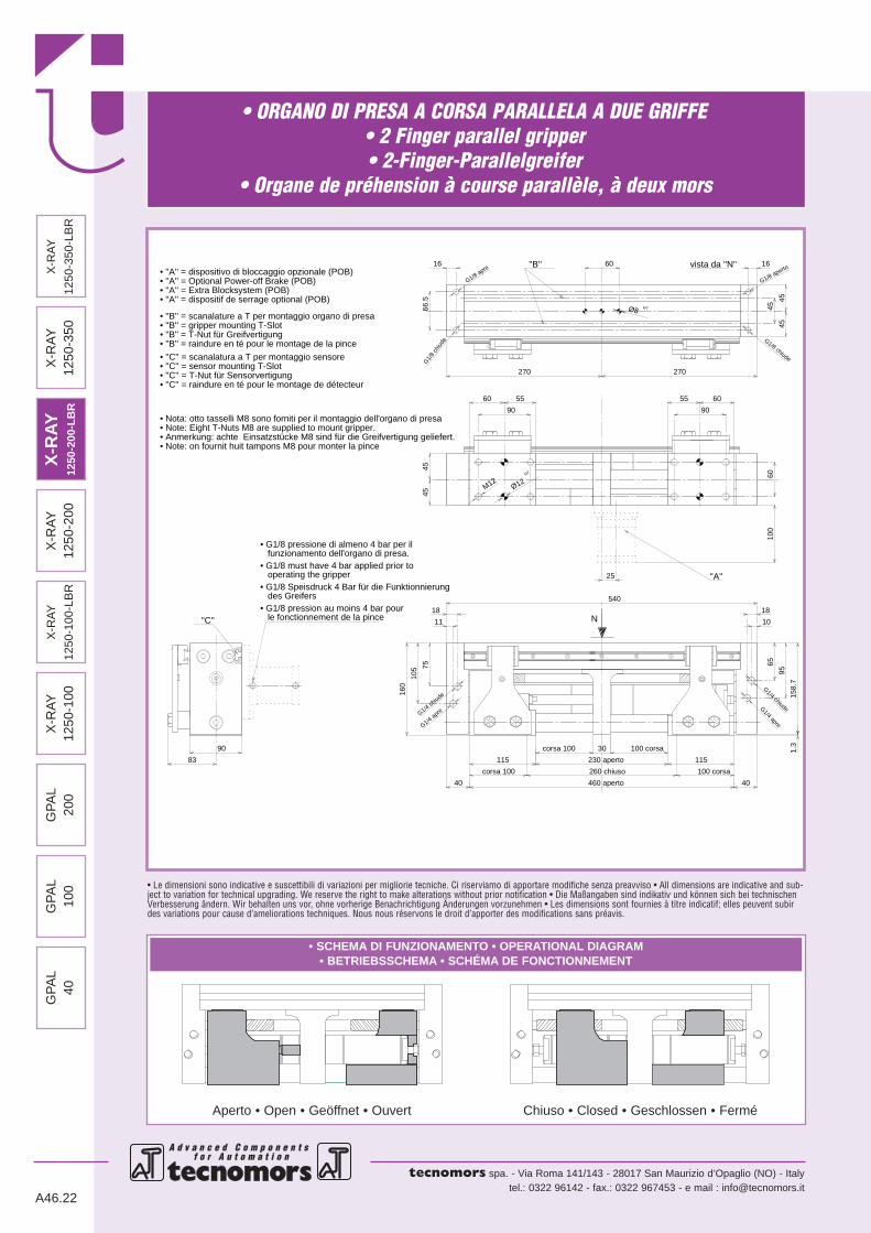
• G1/8 pressione di almeno 4 bar per il funzionamento dell'organo di presa.• G1/8 must have 4 bar applied prior to operating the gripper
• Note: Eight T-Nuts M8 are supplied to mount gripper.
• G1/8 Speisdruck 4 Bar für die Funktionnierung des Greifers• G1/8 pression au moins 4 bar pour le fonctionnement de la pince
''C''
vista da ''N''
''A''
Ø12H7
• ''B'' = scanalature a T per montaggio organo di presa
• ''C'' = sensor mounting T-Slot• ''C'' = T-Nut für Sensorvertigung
• ''B'' = raindure en té pour le montage de la pince
• ''C'' = scanalatura a T per montaggio sensore
• ''B'' = T-Nut für Greifvertigung• ''B'' = gripper mounting T-Slot
• ''A'' = dispositif de serrage optional (POB)• ''A'' = Extra Blocksystem (POB)• ''A'' = Optional Power-off Brake (POB) • ''A'' = dispositivo di bloccaggio opzionale (POB)
• ''C'' = raindure en té pour le montage de détecteur
• Anmerkung: achte Einsatzstücke M8 sind für die Greifvertigung geliefert.
• Nota: otto tasselli M8 sono forniti per il montaggio dell'organo di presa
• Note: on fournit huit tampons M8 pour monter la pince
Ø8 H7
55 60
220
45
16
45
45
90
10
18
40
95
65
1.3
158.
7
6010
0
50 corsa
115
50 corsa
440
260 chiuso
130 aperto
360 aperto
220
90
83
60 55
16
66.5
90
corsa 50
160
18
11
105
40
7545
45
corsa 50
115
60
25
30
X-R
AY
1250
-100
GP
AL
200
GP
AL
100
GP
AL
40X
-RA
Y
1250
-200
-LB
R
X-R
AY
1250
-200
X-R
AY
1250
-350
X-R
AY
1250
-350
-LB
RX
-RAY
1250
-100
-LB
R

• ORGANO DI PRESA A CORSA PARALLELA A DUE GRIFFE• 2 Finger parallel gripper• 2-Finger-Parallelgreifer
• Organe de préhension à course parallèle, à deux mors
A d v a n c e d C o m p o n e n t s f o r A u t o m a t i o n f o r A u t o m a t i o n
tecnomors spa. - Via Roma 141/143 - 28017 San Maurizio d’Opaglio (NO) - Italytel.: 0322 96142 - fax.: 0322 967453 - e mail : [email protected]
A46.19
DATI TECNICICorsa per griffa . . . . . . . . . . . . . . . . . . . . . . . . . . . . . . . . . .50 mmCorsa pistone . . . . . . . . . . . . . . . . . . . . . . . . . . . . . . . . . . .50 mmVolume aria per doppia corsa . . . . . . . . . . . . . . . . . . . . . .373 cm3
Forza teorica di chiusura per griffa a 6 bar . . . . . . . . . . . . . .1055 NForza reale di chiusura per griffa a 6 bar . . . . . . . . . . . . . . . .805 NForza teorica di apertura per griffa a 6 bar . . . . . . . . . . . . . .1180 NForza reale di apertura per griffa a 6 bar . . . . . . . . . . . . . . . .900 NPressione di esercizio . . . . . . . . . . . . . . . . . . . . . . . . . . . .2-12 barRipetibilità . . . . . . . . . . . . . . . . . . . . . . . . . . . . . . . . . . .±0.05 mmPeso . . . . . . . . . . . . . . . . . . . . . . . . . . . . . . . . . . . . . . . . .17.2 KgTemperatura di esercizio . . . . . . . . . . . . . . . . . . . . . . . . . . .5-60 °CCodice articolo . . . . . . . . . . . . . . . . . . . . . . . . . . . . . . .XR100LBRSPECIFICATIONSStroke per jaw . . . . . . . . . . . . . . . . . . . . . . . . . . . . . . . . . . .50 mmPiston stroke . . . . . . . . . . . . . . . . . . . . . . . . . . . . . . . . . . .50 mmDual stroke air volume . . . . . . . . . . . . . . . . . . . . . . . . . . .373 cm3
Theoretical clamping force per jaw at 6 bar . . . . . . . . . . . . .1055 NActual clamping force per jaw at 6 bar. . . . . . . . . . . . . . . . . . 805 NTheoretical opening force per jaw at 6 bar . . . . . . . . . . . . . .1180 NActual opening force per jaw at 6 bar . . . . . . . . . . . . . . . . . . 900 NWorking pressure . . . . . . . . . . . . . . . . . . . . . . . . . . . . . . .2-12 barReproducibility . . . . . . . . . . . . . . . . . . . . . . . . . . . . . . . .±0.05 mmWeight . . . . . . . . . . . . . . . . . . . . . . . . . . . . . . . . . . . . . . . .17.2 KgWorking temperature . . . . . . . . . . . . . . . . . . . . . . . . . . . . .5-60 °CArticle code . . . . . . . . . . . . . . . . . . . . . . . . . . . . . . . . . .XR100LBR
TECHNISCHE DATENHub pro Greiffinger . . . . . . . . . . . . . . . . . . . . . . . . . . . . . . .50 mmKolbenhub . . . . . . . . . . . . . . . . . . . . . . . . . . . . . . . . . . . . .50 mmLuftvolumen pro Doppelhub . . . . . . . . . . . . . . . . . . . . . . .373 cm3
Theoretische Schließkraft pro Greiffinger 6 bar . . . . . . . . . .1055 NReele Schließkraft pro Greiffinger 6 bar . . . . . . . . . . . . . . . . .805 NTheoretische Öffnungskraft pro Greiffinger 6 bar . . . . . . . . . .1180 NReele Öffnungskraft pro Greiffinger 6 bar . . . . . . . . . . . . . . .900 NBetriebsdruck . . . . . . . . . . . . . . . . . . . . . . . . . . . . . . . . . .2-12 barWiederholbarkeit . . . . . . . . . . . . . . . . . . . . . . . . . . . . . .±0.05 mmGewicht . . . . . . . . . . . . . . . . . . . . . . . . . . . . . . . . . . . . . . .17.2 KgBetriebstemperatur . . . . . . . . . . . . . . . . . . . . . . . . . . . . . . .5-60 °CArtikelcode . . . . . . . . . . . . . . . . . . . . . . . . . . . . . . . . . .XR100LBR
DONNÉES TECHNIQUESCourse par griffe . . . . . . . . . . . . . . . . . . . . . . . . . . . . . . . . .50 mmCourse piston . . . . . . . . . . . . . . . . . . . . . . . . . . . . . . . . . . .50 mmVolume d’air pour course double . . . . . . . . . . . . . . . . . . . .373 cm3
Force théorique en fermeture par griffe à 6 bar . . . . . . . . . .1055 NForce réelle en fermeture par griffe à 6 bar . . . . . . . . . . . . . .805 NForce théorique en ouverture par griffe à 6 bar . . . . . . . . . .1180 NForce réelle en ouverture par griffe à 6 bar . . . . . . . . . . . . . .900 NPression d’exercice . . . . . . . . . . . . . . . . . . . . . . . . . . . . . .2-12 barRépétibilité . . . . . . . . . . . . . . . . . . . . . . . . . . . . . . . . . . .±0.05 mmPoids . . . . . . . . . . . . . . . . . . . . . . . . . . . . . . . . . . . . . . . . .17.2 KgTempérature d’exercice . . . . . . . . . . . . . . . . . . . . . . . . . . . .5-60 °CCode article . . . . . . . . . . . . . . . . . . . . . . . . . . . . . . . . . .XR100LBR
140 16020 40 60 L [mm]
F
80 100 120 180 2000
400
450
500
220
550
600
650
700
750
800
850
240
F [N]
L
DIAGRAMMA FORZA DI CHIUSURACLAMPING FORCE DIAGRAM • DIAGRAM SCHLIEßKRAFT
DIAGRAMME DE LA FORCE DE FERMETURE
Valori nei dati tecnici rilevati alla distanza L = 0 mm • Technical specification values read at a distance L = 0 mm• Werte der technischen Daten auf Distanz aufgenommen L = 0 mm • Valeurs des données techniques relevées à la distance L = 0 mm
F = Forza di chiusura reale per griffaL = Distanza di rilevamento
F = True clamping force per jawL = Reading distance
F = Reelle Schließkraft pro GreiffingerL = Messungsabstand
F = Force de fermeture réelle par griffeL = Distance de lecture
P = 6 bar
Attenzione: il valore di L dove si ferma la linea nel grafico rappresenta la lunghezza massima accettabile delle dita di presa pezzoNote: "L" value, where the diagram's line ends, represents jaws' maximum length.
Note : "L" Sur le diagramme, la fin de la ligne représente la longueur maximum des doigts.Hinweis: "L"-Wert, der Punkt an dem die Linie im Diagramm endet stellt die max. Länge der Backen dar.
X-R
AY
1250
-200
GP
AL
100
GP
AL
40G
PA
L20
0X
-RA
Y
1250
-200
-LB
R
X-R
AY
1250
-350
X-R
AY
1250
-350
-LB
R
X-R
AY
1250
-100
X-R
AY12
50-1
00-L
BR

• ORGANO DI PRESA A CORSA PARALLELA A DUE GRIFFE• 2 Finger parallel gripper• 2-Finger-Parallelgreifer
• Organe de préhension à course parallèle, à deux mors
A d v a n c e d C o m p o n e n t s f o r A u t o m a t i o n
tecnomors spa. - Via Roma 141/143 - 28017 San Maurizio d’Opaglio (NO) - Italytel.: 0322 96142 - fax.: 0322 967453 - e mail : [email protected]
• Le dimensioni sono indicative e suscettibili di variazioni per migliorie tecniche. Ci riserviamo di apportare modifiche senza preavviso • All dimensions are indicative and sub-ject to variation for technical upgrading. We reserve the right to make alterations without prior notification • Die Maßangaben sind indikativ und können sich bei technischenVerbesserung ändern. Wir behalten uns vor, ohne vorherige Benachrichtigung Änderungen vorzunehmen • Les dimensions sont fournies à titre indicatif; elles peuvent subirdes variations pour cause d’ameliorations techniques. Nous nous réservons le droit d’apporter des modifications sans préavis.
A46.20
• SCHEMA DI FUNZIONAMENTO • OPERATIONAL DIAGRAM• BETRIEBSSCHEMA • SCHÉMA DE FONCTIONNEMENT
Aperto • Open • Geöffnet • Ouvert Chiuso • Closed • Geschlossen • Fermé
• Note: on fournit huit tampons M8 pour monter la pince
• ''C'' = raindure en té pour le montage de détecteur
• G1/8 pression au moins 4 bar pour le fonctionnement de la pince
• G1/8 must have 4 bar applied prior to operating the gripper• G1/8 Speisdruck 4 Bar für die Funktionnierung des Greifers
• ''A'' = dispositif de serrage optional (POB)G1/4 ch
iude
• Note: Eight T-Nuts M8 are supplied to mount gripper.
• G1/8 pressione di almeno 4 bar per il funzionamento dell'organo di presa.
• ''B'' = raindure en té pour le montage de la pince
G1/8 apre
• Nota: otto tasselli M8 sono forniti per il montaggio dell'organo di presa
• Anmerkung: achte Einsatzstücke M8 sind für die Greifvertigung geliefert. N
G1/8 aperto
G1/8 chiude
G1/8 chiude
G1/4 chiudeG1/4 apreG1/4 apre
''C''
• ''B'' = scanalature a T per montaggio organo di presa
• ''C'' = scanalatura a T per montaggio sensore• ''C'' = sensor mounting T-Slot
• ''A'' = Extra Blocksystem (POB)• ''A'' = Optional Power-off Brake (POB)
• ''B'' = gripper mounting T-Slot• ''B'' = T-Nut für Greifvertigung
• ''C'' = T-Nut für Sensorvertigung
• ''A'' = dispositivo di bloccaggio opzionale (POB)
''B'' vista da ''N''
Ø8 H7
''A''
M12Ø12
H7
230 aperto
460 aperto
260 chiuso
16
270
45
16
270
66.5
60
25
30
10
18
40
95
65
100 corsa 1.3
158.
7
18
11
160
105
corsa 100
40
75
540
corsa 100
115 115
100 corsa
4545
90
6010
0
6055
90
60 55
4545
90
X-R
AY12
50-2
00G
PA
L10
0G
PA
L40
GP
AL
200
X-R
AY
1250
-200
-LB
R
X-R
AY
1250
-100
-LB
R
X-R
AY
1250
-350
X-R
AY
1250
-100
X-R
AY
1250
-350
-LB
R
GP
AL
100
GP
AL
40G
PA
L20
0X
-RA
Y
1250
-200
-LB
R
X-R
AY
1250
-100
-LB
R
X-R
AY
1250
-350
X-R
AY
1250
-350
-LB
R
• ORGANO DI PRESA A CORSA PARALLELA A DUE GRIFFE• 2 Finger parallel gripper• 2-Finger-Parallelgreifer
• Organe de préhension à course parallèle, à deux mors
A d v a n c e d C o m p o n e n t s f o r A u t o m a t i o n f o r A u t o m a t i o n
tecnomors spa. - Via Roma 141/143 - 28017 San Maurizio d’Opaglio (NO) - Italytel.: 0322 96142 - fax.: 0322 967453 - e mail : [email protected]
A46.21
DATI TECNICICorsa per griffa . . . . . . . . . . . . . . . . . . . . . . . . . . . . . . . . .100 mmCorsa pistone . . . . . . . . . . . . . . . . . . . . . . . . . . . . . . . . . .100 mmVolume aria per doppia corsa . . . . . . . . . . . . . . . . . . . . . .746 cm3
Forza teorica di chiusura per griffa a 6 bar . . . . . . . . . . . . . .1055 NForza reale di chiusura per griffa a 6 bar . . . . . . . . . . . . . . . .805 NForza teorica di apertura per griffa a 6 bar . . . . . . . . . . . . . .1180 NForza reale di apertura per griffa a 6 bar . . . . . . . . . . . . . . . .900 NPressione di esercizio . . . . . . . . . . . . . . . . . . . . . . . . . . . .2-12 barRipetibilità . . . . . . . . . . . . . . . . . . . . . . . . . . . . . . . . . . .±0.05 mmPeso . . . . . . . . . . . . . . . . . . . . . . . . . . . . . . . . . . . . . . . . .13.6 KgTemperatura di esercizio . . . . . . . . . . . . . . . . . . . . . . . . . . .5-60 °CCodice articolo . . . . . . . . . . . . . . . . . . . . . . . . . . . . . . .XR125ABD
SPECIFICATIONSStroke per jaw . . . . . . . . . . . . . . . . . . . . . . . . . . . . . . . . . .100 mmPiston stroke . . . . . . . . . . . . . . . . . . . . . . . . . . . . . . . . . . .100 mmDual stroke air volume . . . . . . . . . . . . . . . . . . . . . . . . . . .746 cm3
Theoretical clamping force per jaw at 6 bar . . . . . . . . . . . . .1055 NActual clamping force per jaw at 6 bar. . . . . . . . . . . . . . . . . . 805 NTheoretical opening force per jaw at 6 bar . . . . . . . . . . . . . .1180 NActual opening force per jaw at 6 bar . . . . . . . . . . . . . . . . . . 900 NWorking pressure . . . . . . . . . . . . . . . . . . . . . . . . . . . . . . .2-12 barReproducibility . . . . . . . . . . . . . . . . . . . . . . . . . . . . . . . .±0.05 mmWeight . . . . . . . . . . . . . . . . . . . . . . . . . . . . . . . . . . . . . . . .13.6 KgWorking temperature . . . . . . . . . . . . . . . . . . . . . . . . . . . . .5-60 °CArticle code . . . . . . . . . . . . . . . . . . . . . . . . . . . . . . . . . .XR125ABD
TECHNISCHE DATENHub pro Greiffinger . . . . . . . . . . . . . . . . . . . . . . . . . . . . . .100 mmKolbenhub . . . . . . . . . . . . . . . . . . . . . . . . . . . . . . . . . . . .100 mmLuftvolumen pro Doppelhub . . . . . . . . . . . . . . . . . . . . . . .746 cm3
Theoretische Schließkraft pro Greiffinger 6 bar . . . . . . . . . .1055 NReele Schließkraft pro Greiffinger 6 bar . . . . . . . . . . . . . . . . .805 NTheoretische Öffnungskraft pro Greiffinger 6 bar . . . . . . . . . .1180 NReele Öffnungskraft pro Greiffinger 6 bar . . . . . . . . . . . . . . .900 NBetriebsdruck . . . . . . . . . . . . . . . . . . . . . . . . . . . . . . . . . .2-12 barWiederholbarkeit . . . . . . . . . . . . . . . . . . . . . . . . . . . . . .±0.05 mmGewicht . . . . . . . . . . . . . . . . . . . . . . . . . . . . . . . . . . . . . . .13.6 KgBetriebstemperatur . . . . . . . . . . . . . . . . . . . . . . . . . . . . . . .5-60 °CArtikelcode . . . . . . . . . . . . . . . . . . . . . . . . . . . . . . . . . .XR125ABD
DONNÉES TECHNIQUESCourse par griffe . . . . . . . . . . . . . . . . . . . . . . . . . . . . . . . .100 mmCourse piston . . . . . . . . . . . . . . . . . . . . . . . . . . . . . . . . . .100 mmVolume d’air pour course double . . . . . . . . . . . . . . . . . . . .746 cm3
Force théorique en fermeture par griffe à 6 bar . . . . . . . . . .1055 NForce réelle en fermeture par griffe à 6 bar . . . . . . . . . . . . . .805 NForce théorique en ouverture par griffe à 6 bar . . . . . . . . . .1180 NForce réelle en ouverture par griffe à 6 bar . . . . . . . . . . . . . .900 NPression d’exercice . . . . . . . . . . . . . . . . . . . . . . . . . . . . . .2-12 barRépétibilité . . . . . . . . . . . . . . . . . . . . . . . . . . . . . . . . . . .±0.05 mmPoids . . . . . . . . . . . . . . . . . . . . . . . . . . . . . . . . . . . . . . . . .13.6 KgTempérature d’exercice . . . . . . . . . . . . . . . . . . . . . . . . . . . .5-60 °CCode article . . . . . . . . . . . . . . . . . . . . . . . . . . . . . . . . . .XR125ABD
140 16020 40 60 L [mm]
F
80 100 120 180 2000
400
450
500
220
550
600
650
700
750
800
850
240
F [N]
L
DIAGRAMMA FORZA DI CHIUSURACLAMPING FORCE DIAGRAM • DIAGRAM SCHLIEßKRAFT
DIAGRAMME DE LA FORCE DE FERMETURE
Valori nei dati tecnici rilevati alla distanza L = 0 mm • Technical specification values read at a distance L = 0 mm• Werte der technischen Daten auf Distanz aufgenommen L = 0 mm • Valeurs des données techniques relevées à la distance L = 0 mm
F = Forza di chiusura reale per griffaL = Distanza di rilevamento
F = True clamping force per jawL = Reading distance
F = Reelle Schließkraft pro GreiffingerL = Messungsabstand
F = Force de fermeture réelle par griffeL = Distance de lecture
P = 6 bar
Attenzione: il valore di L dove si ferma la linea nel grafico rappresenta la lunghezza massima accettabile delle dita di presa pezzoNote: "L" value, where the diagram's line ends, represents jaws' maximum length.
Note : "L" Sur le diagramme, la fin de la ligne représente la longueur maximum des doigts.Hinweis: "L"-Wert, der Punkt an dem die Linie im Diagramm endet stellt die max. Länge der Backen dar.
X-R
AY12
50-2
00X
-RA
Y12
50-1
00
• ORGANO DI PRESA A CORSA PARALLELA A DUE GRIFFE• 2 Finger parallel gripper• 2-Finger-Parallelgreifer
• Organe de préhension à course parallèle, à deux mors
A d v a n c e d C o m p o n e n t s f o r A u t o m a t i o n
tecnomors spa. - Via Roma 141/143 - 28017 San Maurizio d’Opaglio (NO) - Italytel.: 0322 96142 - fax.: 0322 967453 - e mail : [email protected]
• Le dimensioni sono indicative e suscettibili di variazioni per migliorie tecniche. Ci riserviamo di apportare modifiche senza preavviso • All dimensions are indicative and sub-ject to variation for technical upgrading. We reserve the right to make alterations without prior notification • Die Maßangaben sind indikativ und können sich bei technischenVerbesserung ändern. Wir behalten uns vor, ohne vorherige Benachrichtigung Änderungen vorzunehmen • Les dimensions sont fournies à titre indicatif; elles peuvent subirdes variations pour cause d’ameliorations techniques. Nous nous réservons le droit d’apporter des modifications sans préavis.
A46.22
• SCHEMA DI FUNZIONAMENTO • OPERATIONAL DIAGRAM• BETRIEBSSCHEMA • SCHÉMA DE FONCTIONNEMENT
Aperto • Open • Geöffnet • Ouvert Chiuso • Closed • Geschlossen • Fermé
• G1/8 Speisdruck 4 Bar für die Funktionnierung des Greifers
G1/4 chiudeG1/4 apre
• G1/8 must have 4 bar applied prior to operating the gripper
• Note: Eight T-Nuts M8 are supplied to mount gripper.
• G1/8 pressione di almeno 4 bar per il funzionamento dell'organo di presa.
N
G1/8 aperto
G1/8 chiude
G1/8 apre
G1/
8 ch
iude
G1/4 chiude
G1/4 apre
M12
''B''
''A''
vista da ''N''
Ø12H7
• ''B'' = scanalature a T per montaggio organo di presa
• ''C'' = sensor mounting T-Slot• ''C'' = T-Nut für Sensorvertigung
• ''B'' = raindure en té pour le montage de la pince
• ''C'' = scanalatura a T per montaggio sensore
• ''B'' = T-Nut für Greifvertigung• ''B'' = gripper mounting T-Slot
• ''A'' = dispositif de serrage optional (POB)• ''A'' = Extra Blocksystem (POB)• ''A'' = Optional Power-off Brake (POB) • ''A'' = dispositivo di bloccaggio opzionale (POB)
• ''C'' = raindure en té pour le montage de détecteur
• Anmerkung: achte Einsatzstücke M8 sind für die Greifvertigung geliefert.
• Nota: otto tasselli M8 sono forniti per il montaggio dell'organo di presa
• Note: on fournit huit tampons M8 pour monter la pince
''C''• G1/8 pression au moins 4 bar pour le fonctionnement de la pince
Ø8 H7
55
260 chiuso
10
18
4095
65
1.3
158.
7
100 corsa
115
100 corsa
90
6010
0
60
270
45
16
45
45
540
230 aperto
460 aperto
270
90
83
60 55
16
66.5
90
corsa 100
160
18
11
105
40
7545
45
corsa 100
115
60
25
30
X-R
AY
1250
-100
GP
AL
200
GP
AL
100
X-R
AY
1250
-100
-LB
R
X-R
AY
1250
-200
X-R
AY
1250
-350
X-R
AY
1250
-350
-LB
R
GP
AL
40X
-RAY
1250
-200
-LB
R

• ORGANO DI PRESA A CORSA PARALLELA A DUE GRIFFE• 2 Finger parallel gripper• 2-Finger-Parallelgreifer
• Organe de préhension à course parallèle, à deux mors
A d v a n c e d C o m p o n e n t s f o r A u t o m a t i o n f o r A u t o m a t i o n
tecnomors spa. - Via Roma 141/143 - 28017 San Maurizio d’Opaglio (NO) - Italytel.: 0322 96142 - fax.: 0322 967453 - e mail : [email protected]
A46.23
DATI TECNICICorsa per griffa . . . . . . . . . . . . . . . . . . . . . . . . . . . . . . . . .100 mmCorsa pistone . . . . . . . . . . . . . . . . . . . . . . . . . . . . . . . . . .100 mmVolume aria per doppia corsa . . . . . . . . . . . . . . . . . . . . . .746 cm3
Forza teorica di chiusura per griffa a 6 bar . . . . . . . . . . . . . .1055 NForza reale di chiusura per griffa a 6 bar . . . . . . . . . . . . . . . .805 NForza teorica di apertura per griffa a 6 bar . . . . . . . . . . . . . .1180 NForza reale di apertura per griffa a 6 bar . . . . . . . . . . . . . . . .900 NPressione di esercizio . . . . . . . . . . . . . . . . . . . . . . . . . . . .2-12 barRipetibilità . . . . . . . . . . . . . . . . . . . . . . . . . . . . . . . . . . .±0.05 mmPeso . . . . . . . . . . . . . . . . . . . . . . . . . . . . . . . . . . . . . . . . .18.2 KgTemperatura di esercizio . . . . . . . . . . . . . . . . . . . . . . . . . . .5-60 °CCodice articolo . . . . . . . . . . . . . . . . . . . . . . . . . . . . . . .XR200LBR
SPECIFICATIONSStroke per jaw . . . . . . . . . . . . . . . . . . . . . . . . . . . . . . . . . .100 mmPiston stroke . . . . . . . . . . . . . . . . . . . . . . . . . . . . . . . . . . .100 mmDual stroke air volume . . . . . . . . . . . . . . . . . . . . . . . . . . .746 cm3
Theoretical clamping force per jaw at 6 bar . . . . . . . . . . . . .1055 NActual clamping force per jaw at 6 bar. . . . . . . . . . . . . . . . . . 805 NTheoretical opening force per jaw at 6 bar . . . . . . . . . . . . . .1180 NActual opening force per jaw at 6 bar . . . . . . . . . . . . . . . . . . 900 NWorking pressure . . . . . . . . . . . . . . . . . . . . . . . . . . . . . . .2-12 barReproducibility . . . . . . . . . . . . . . . . . . . . . . . . . . . . . . . .±0.05 mmWeight . . . . . . . . . . . . . . . . . . . . . . . . . . . . . . . . . . . . . . . .18.2 KgWorking temperature . . . . . . . . . . . . . . . . . . . . . . . . . . . . .5-60 °CArticle code . . . . . . . . . . . . . . . . . . . . . . . . . . . . . . . . . .XR200LBR
TECHNISCHE DATENHub pro Greiffinger . . . . . . . . . . . . . . . . . . . . . . . . . . . . . .100 mmKolbenhub . . . . . . . . . . . . . . . . . . . . . . . . . . . . . . . . . . . .100 mmLuftvolumen pro Doppelhub . . . . . . . . . . . . . . . . . . . . . . .746 cm3
Theoretische Schließkraft pro Greiffinger 6 bar . . . . . . . . . .1055 NReele Schließkraft pro Greiffinger 6 bar . . . . . . . . . . . . . . . . .805 NTheoretische Öffnungskraft pro Greiffinger 6 bar . . . . . . . . . .1180 NReele Öffnungskraft pro Greiffinger 6 bar . . . . . . . . . . . . . . .900 NBetriebsdruck . . . . . . . . . . . . . . . . . . . . . . . . . . . . . . . . . .2-12 barWiederholbarkeit . . . . . . . . . . . . . . . . . . . . . . . . . . . . . .±0.05 mmGewicht . . . . . . . . . . . . . . . . . . . . . . . . . . . . . . . . . . . . . . .18.2 KgBetriebstemperatur . . . . . . . . . . . . . . . . . . . . . . . . . . . . . . .5-60 °CArtikelcode . . . . . . . . . . . . . . . . . . . . . . . . . . . . . . . . . .XR200LBR
DONNÉES TECHNIQUESCourse par griffe . . . . . . . . . . . . . . . . . . . . . . . . . . . . . . . .100 mmCourse piston . . . . . . . . . . . . . . . . . . . . . . . . . . . . . . . . . .100 mmVolume d’air pour course double . . . . . . . . . . . . . . . . . . . .746 cm3
Force théorique en fermeture par griffe à 6 bar . . . . . . . . . .1055 NForce réelle en fermeture par griffe à 6 bar . . . . . . . . . . . . . .805 NForce théorique en ouverture par griffe à 6 bar . . . . . . . . . .1180 NForce réelle en ouverture par griffe à 6 bar . . . . . . . . . . . . . .900 NPression d’exercice . . . . . . . . . . . . . . . . . . . . . . . . . . . . . .2-12 barRépétibilité . . . . . . . . . . . . . . . . . . . . . . . . . . . . . . . . . . .±0.05 mmPoids . . . . . . . . . . . . . . . . . . . . . . . . . . . . . . . . . . . . . . . . .18.2 KgTempérature d’exercice . . . . . . . . . . . . . . . . . . . . . . . . . . . .5-60 °CCode article . . . . . . . . . . . . . . . . . . . . . . . . . . . . . . . . . .XR200LBR
140 16020 40 60 L [mm]
F
80 100 120 180 2000
400
450
500
220
550
600
650
700
750
800
850
240
F [N]
L
DIAGRAMMA FORZA DI CHIUSURACLAMPING FORCE DIAGRAM • DIAGRAM SCHLIEßKRAFT
DIAGRAMME DE LA FORCE DE FERMETURE
Valori nei dati tecnici rilevati alla distanza L = 0 mm • Technical specification values read at a distance L = 0 mm• Werte der technischen Daten auf Distanz aufgenommen L = 0 mm • Valeurs des données techniques relevées à la distance L = 0 mm
F = Forza di chiusura reale per griffaL = Distanza di rilevamento
F = True clamping force per jawL = Reading distance
F = Reelle Schließkraft pro GreiffingerL = Messungsabstand
F = Force de fermeture réelle par griffeL = Distance de lecture
P = 6 bar
Attenzione: il valore di L dove si ferma la linea nel grafico rappresenta la lunghezza massima accettabile delle dita di presa pezzoNote: "L" value, where the diagram's line ends, represents jaws' maximum length.
Note : "L" Sur le diagramme, la fin de la ligne représente la longueur maximum des doigts.Hinweis: "L"-Wert, der Punkt an dem die Linie im Diagramm endet stellt die max. Länge der Backen dar.
X-R
AY
1250
-200
GP
AL
100
GP
AL
40G
PA
L20
0X
-RA
Y
1250
-100
-LB
R
X-R
AY
1250
-350
X-R
AY
1250
-350
-LB
R
X-R
AY
1250
-100
X-R
AY12
50-2
00-L
BR

X-R
AY12
50-3
50
• ORGANO DI PRESA A CORSA PARALLELA A DUE GRIFFE• 2 Finger parallel gripper• 2-Finger-Parallelgreifer
• Organe de préhension à course parallèle, à deux mors
A d v a n c e d C o m p o n e n t s f o r A u t o m a t i o n
tecnomors spa. - Via Roma 141/143 - 28017 San Maurizio d’Opaglio (NO) - Italytel.: 0322 96142 - fax.: 0322 967453 - e mail : [email protected]
• Le dimensioni sono indicative e suscettibili di variazioni per migliorie tecniche. Ci riserviamo di apportare modifiche senza preavviso • All dimensions are indicative and sub-ject to variation for technical upgrading. We reserve the right to make alterations without prior notification • Die Maßangaben sind indikativ und können sich bei technischenVerbesserung ändern. Wir behalten uns vor, ohne vorherige Benachrichtigung Änderungen vorzunehmen • Les dimensions sont fournies à titre indicatif; elles peuvent subirdes variations pour cause d’ameliorations techniques. Nous nous réservons le droit d’apporter des modifications sans préavis.
A46.24
• SCHEMA DI FUNZIONAMENTO • OPERATIONAL DIAGRAM• BETRIEBSSCHEMA • SCHÉMA DE FONCTIONNEMENT
Aperto • Open • Geöffnet • Ouvert Chiuso • Closed • Geschlossen • Fermé
• Note: Eight T-Nuts M8 are supplied to mount gripper.• Anmerkung: achte Einsatzstücke M8 sind für die Greifvertigung geliefert.
G1/8 apre
G1/4 chiude
• ''B'' = scanalature a T per montaggio organo di presa
• ''C'' = sensor mounting T-Slot
• Nota: otto tasselli M8 sono forniti per il montaggio dell'organo di presa
• ''C'' = T-Nut für Sensorvertigung
• ''B'' = raindure en té pour le montage de la pince
• ''C'' = scanalatura a T per montaggio sensore
• ''B'' = T-Nut für Greifvertigung• ''B'' = gripper mounting T-Slot
• ''A'' = dispositif de serrage optional (POB)• ''A'' = Extra Blocksystem (POB)• ''A'' = Optional Power-off Brake (POB) • ''A'' = dispositivo di bloccaggio opzionale (POB)
• ''C'' = raindure en té pour le montage de détecteur
''A''
''B''
N''C''
• G1/8 pression au moins 4 bar pour le fonctionnement de la pince
• G1/8 Speisdruck 4 Bar für die Funktionnierung des Greifers
• G1/8 must have 4 bar applied prior to operating the gripper
• G1/8 pressione di almeno 4 bar per il funzionamento dell'organo di presa.
• Note: on fournit huit tampons M8 pour monter la pince
G1/8 chiude
G1/4 chiudeG1/4 apre
vista da ''N''
G1/8 aperto
G1/8 chiude
Ø8 H7
G1/4 apre
M12Ø12
H7
90
16
345
66.5
10
18
40
95
65
1.3
158.
7
60
90
6010
0
55
345
16
45
4545
175 corsa
115
175 corsa
25
30corsa 175
60
690
160
18
11
105
40
75
90
60 55
4545
260 chiuso
380 aperto
610 aperto
corsa 175
115
X-R
AY
1250
-100
GP
AL
200
GP
AL
100
GP
AL
40X
-RA
Y
1250
-100
-LB
R
X-R
AY
1250
-200
X-R
AY
1250
-200
-LB
R
X-R
AY
1250
-350
-LB
R

• ORGANO DI PRESA A CORSA PARALLELA A DUE GRIFFE• 2 Finger parallel gripper• 2-Finger-Parallelgreifer
• Organe de préhension à course parallèle, à deux mors
A d v a n c e d C o m p o n e n t s f o r A u t o m a t i o n f o r A u t o m a t i o n
tecnomors spa. - Via Roma 141/143 - 28017 San Maurizio d’Opaglio (NO) - Italytel.: 0322 96142 - fax.: 0322 967453 - e mail : [email protected]
A46.25
DATI TECNICICorsa per griffa . . . . . . . . . . . . . . . . . . . . . . . . . . . . . . . . .175 mmCorsa pistone . . . . . . . . . . . . . . . . . . . . . . . . . . . . . . . . . .175 mmVolume aria per doppia corsa . . . . . . . . . . . . . . . . . . . . .1306 cm3
Forza teorica di chiusura per griffa a 6 bar . . . . . . . . . . . . . .1055 NForza reale di chiusura per griffa a 6 bar . . . . . . . . . . . . . . . .805 NForza teorica di apertura per griffa a 6 bar . . . . . . . . . . . . . .1180 NForza reale di apertura per griffa a 6 bar . . . . . . . . . . . . . . . .900 NPressione di esercizio . . . . . . . . . . . . . . . . . . . . . . . . . . . .2-12 barRipetibilità . . . . . . . . . . . . . . . . . . . . . . . . . . . . . . . . . . .±0.05 mmPeso . . . . . . . . . . . . . . . . . . . . . . . . . . . . . . . . . . . . . . . . . . .15 KgTemperatura di esercizio . . . . . . . . . . . . . . . . . . . . . . . . . . .5-60 °CCodice articolo . . . . . . . . . . . . . . . . . . . . . . . . . . . . . . .XR125ABE
SPECIFICATIONSStroke per jaw . . . . . . . . . . . . . . . . . . . . . . . . . . . . . . . . . .175 mmPiston stroke . . . . . . . . . . . . . . . . . . . . . . . . . . . . . . . . . . .175 mmDual stroke air volume . . . . . . . . . . . . . . . . . . . . . . . . . .1306 cm3
Theoretical clamping force per jaw at 6 bar . . . . . . . . . . . . .1055 NActual clamping force per jaw at 6 bar. . . . . . . . . . . . . . . . . . 805 NTheoretical opening force per jaw at 6 bar . . . . . . . . . . . . . .1180 NActual opening force per jaw at 6 bar . . . . . . . . . . . . . . . . . . 900 NWorking pressure . . . . . . . . . . . . . . . . . . . . . . . . . . . . . . .2-12 barReproducibility . . . . . . . . . . . . . . . . . . . . . . . . . . . . . . . .±0.05 mmWeight . . . . . . . . . . . . . . . . . . . . . . . . . . . . . . . . . . . . . . . . .15 KgWorking temperature . . . . . . . . . . . . . . . . . . . . . . . . . . . . .5-60 °CArticle code . . . . . . . . . . . . . . . . . . . . . . . . . . . . . . . . . .XR125ABE
TECHNISCHE DATENHub pro Greiffinger . . . . . . . . . . . . . . . . . . . . . . . . . . . . . .175 mmKolbenhub . . . . . . . . . . . . . . . . . . . . . . . . . . . . . . . . . . . .175 mmLuftvolumen pro Doppelhub . . . . . . . . . . . . . . . . . . . . . .1306 cm3
Theoretische Schließkraft pro Greiffinger 6 bar . . . . . . . . . .1055 NReele Schließkraft pro Greiffinger 6 bar . . . . . . . . . . . . . . . . .805 NTheoretische Öffnungskraft pro Greiffinger 6 bar . . . . . . . . . .1180 NReele Öffnungskraft pro Greiffinger 6 bar . . . . . . . . . . . . . . .900 NBetriebsdruck . . . . . . . . . . . . . . . . . . . . . . . . . . . . . . . . . .2-12 barWiederholbarkeit . . . . . . . . . . . . . . . . . . . . . . . . . . . . . .±0.05 mmGewicht . . . . . . . . . . . . . . . . . . . . . . . . . . . . . . . . . . . . . . . .15 KgBetriebstemperatur . . . . . . . . . . . . . . . . . . . . . . . . . . . . . . .5-60 °CArtikelcode . . . . . . . . . . . . . . . . . . . . . . . . . . . . . . . . . .XR125ABE
DONNÉES TECHNIQUESCourse par griffe . . . . . . . . . . . . . . . . . . . . . . . . . . . . . . . .175 mmCourse piston . . . . . . . . . . . . . . . . . . . . . . . . . . . . . . . . . .175 mmVolume d’air pour course double . . . . . . . . . . . . . . . . . . .1306 cm3
Force théorique en fermeture par griffe à 6 bar . . . . . . . . . .1055 NForce réelle en fermeture par griffe à 6 bar . . . . . . . . . . . . . .805 NForce théorique en ouverture par griffe à 6 bar . . . . . . . . . .1180 NForce réelle en ouverture par griffe à 6 bar . . . . . . . . . . . . . .900 NPression d’exercice . . . . . . . . . . . . . . . . . . . . . . . . . . . . . .2-12 barRépétibilité . . . . . . . . . . . . . . . . . . . . . . . . . . . . . . . . . . .±0.05 mmPoids . . . . . . . . . . . . . . . . . . . . . . . . . . . . . . . . . . . . . . . . . .15 KgTempérature d’exercice . . . . . . . . . . . . . . . . . . . . . . . . . . . .5-60 °CCode article . . . . . . . . . . . . . . . . . . . . . . . . . . . . . . . . . .XR125ABE
140 16020 40 60 L [mm]
F
80 100 120 180 2000
400
450
500
220
550
600
650
700
750
800
850
240
F [N]
L
DIAGRAMMA FORZA DI CHIUSURACLAMPING FORCE DIAGRAM • DIAGRAM SCHLIEßKRAFT
DIAGRAMME DE LA FORCE DE FERMETURE
Valori nei dati tecnici rilevati alla distanza L = 0 mm • Technical specification values read at a distance L = 0 mm• Werte der technischen Daten auf Distanz aufgenommen L = 0 mm • Valeurs des données techniques relevées à la distance L = 0 mm
F = Forza di chiusura reale per griffaL = Distanza di rilevamento
F = True clamping force per jawL = Reading distance
F = Reelle Schließkraft pro GreiffingerL = Messungsabstand
F = Force de fermeture réelle par griffeL = Distance de lecture
P = 6 bar
Attenzione: il valore di L dove si ferma la linea nel grafico rappresenta la lunghezza massima accettabile delle dita di presa pezzoNote: "L" value, where the diagram's line ends, represents jaws' maximum length.
Note : "L" Sur le diagramme, la fin de la ligne représente la longueur maximum des doigts.Hinweis: "L"-Wert, der Punkt an dem die Linie im Diagramm endet stellt die max. Länge der Backen dar.
X-R
AY12
50-3
50X
-RA
Y12
50-2
00X
-RA
Y12
50-1
00G
PA
L10
0G
PA
L40
GP
AL
200
X-R
AY
1250
-200
-LB
R
X-R
AY
1250
-100
-LB
R
X-R
AY
1250
-350
-LB
R
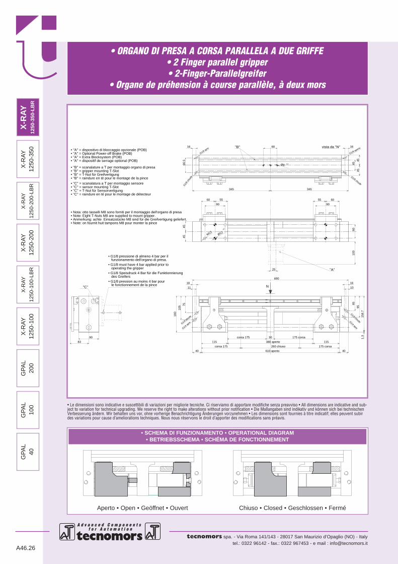
• ORGANO DI PRESA A CORSA PARALLELA A DUE GRIFFE• 2 Finger parallel gripper• 2-Finger-Parallelgreifer
• Organe de préhension à course parallèle, à deux mors
A d v a n c e d C o m p o n e n t s f o r A u t o m a t i o n
tecnomors spa. - Via Roma 141/143 - 28017 San Maurizio d’Opaglio (NO) - Italytel.: 0322 96142 - fax.: 0322 967453 - e mail : [email protected]
• Le dimensioni sono indicative e suscettibili di variazioni per migliorie tecniche. Ci riserviamo di apportare modifiche senza preavviso • All dimensions are indicative and sub-ject to variation for technical upgrading. We reserve the right to make alterations without prior notification • Die Maßangaben sind indikativ und können sich bei technischenVerbesserung ändern. Wir behalten uns vor, ohne vorherige Benachrichtigung Änderungen vorzunehmen • Les dimensions sont fournies à titre indicatif; elles peuvent subirdes variations pour cause d’ameliorations techniques. Nous nous réservons le droit d’apporter des modifications sans préavis.
A46.26
• SCHEMA DI FUNZIONAMENTO • OPERATIONAL DIAGRAM• BETRIEBSSCHEMA • SCHÉMA DE FONCTIONNEMENT
Aperto • Open • Geöffnet • Ouvert Chiuso • Closed • Geschlossen • Fermé
N
G1/8 apre
G1/
8 ch
iude
G1/8 aperto
G1/8 chiude
G1/4 chiude
G1/4 chiudeG1/4 apreG1/4 apre
M12
• G1/8 must have 4 bar applied prior to operating the gripper
''C''
• G1/8 Speisdruck 4 Bar für die Funktionnierung des Greifers
• G1/8 pressione di almeno 4 bar per il funzionamento dell'organo di presa.
• G1/8 pression au moins 4 bar pour le fonctionnement de la pince
• Note: Eight T-Nuts M8 are supplied to mount gripper.• Anmerkung: achte Einsatzstücke M8 sind für die Greifvertigung geliefert.
• Nota: otto tasselli M8 sono forniti per il montaggio dell'organo di presa
• Note: on fournit huit tampons M8 pour monter la pince
• ''B'' = scanalature a T per montaggio organo di presa
• ''C'' = sensor mounting T-Slot• ''C'' = T-Nut für Sensorvertigung
• ''B'' = raindure en té pour le montage de la pince
• ''C'' = scanalatura a T per montaggio sensore
• ''B'' = T-Nut für Greifvertigung• ''B'' = gripper mounting T-Slot
• ''A'' = dispositif de serrage optional (POB)• ''A'' = Extra Blocksystem (POB)• ''A'' = Optional Power-off Brake (POB) • ''A'' = dispositivo di bloccaggio opzionale (POB)
• ''C'' = raindure en té pour le montage de détecteur
''B'' vista da ''N''
Ø8 H7
''A''
Ø12H7
90
83
55 60
345 345
45
60 55
16
66.5
16
45
45
60
9090
10
18
40
95
65
1.3
158.
7
6010
0
175 corsa
115
175 corsa
25
30corsa 175
690
160
18
11
105
40
7545
45
260 chiuso
380 aperto
610 aperto
corsa 175
115
X-R
AY
1250
-100
GP
AL
200
GP
AL
100
X-R
AY
1250
-100
-LB
R
X-R
AY
1250
-200
X-R
AY
1250
-200
-LB
R
X-R
AY
1250
-350
GP
AL
40X
-RAY
1250
-350
-LB
R

• ORGANO DI PRESA A CORSA PARALLELA A DUE GRIFFE• 2 Finger parallel gripper• 2-Finger-Parallelgreifer
• Organe de préhension à course parallèle, à deux mors
A d v a n c e d C o m p o n e n t s f o r A u t o m a t i o n f o r A u t o m a t i o n
tecnomors spa. - Via Roma 141/143 - 28017 San Maurizio d’Opaglio (NO) - Italytel.: 0322 96142 - fax.: 0322 967453 - e mail : [email protected]
A46.27
DATI TECNICICorsa per griffa . . . . . . . . . . . . . . . . . . . . . . . . . . . . . . . . .175 mmCorsa pistone . . . . . . . . . . . . . . . . . . . . . . . . . . . . . . . . . .175 mmVolume aria per doppia corsa . . . . . . . . . . . . . . . . . . . . .1306 cm3
Forza teorica di chiusura per griffa a 6 bar . . . . . . . . . . . . . .1055 NForza reale di chiusura per griffa a 6 bar . . . . . . . . . . . . . . . .805 NForza teorica di apertura per griffa a 6 bar . . . . . . . . . . . . . .1180 NForza reale di apertura per griffa a 6 bar . . . . . . . . . . . . . . . .900 NPressione di esercizio . . . . . . . . . . . . . . . . . . . . . . . . . . . .2-12 barRipetibilità . . . . . . . . . . . . . . . . . . . . . . . . . . . . . . . . . . .±0.05 mmPeso . . . . . . . . . . . . . . . . . . . . . . . . . . . . . . . . . . . . . . . . .21.8 KgTemperatura di esercizio . . . . . . . . . . . . . . . . . . . . . . . . . . .5-60 °CCodice articolo . . . . . . . . . . . . . . . . . . . . . . . . . . . . . . .XR350LBR
SPECIFICATIONSStroke per jaw . . . . . . . . . . . . . . . . . . . . . . . . . . . . . . . . . .175 mmPiston stroke . . . . . . . . . . . . . . . . . . . . . . . . . . . . . . . . . . .175 mmDual stroke air volume . . . . . . . . . . . . . . . . . . . . . . . . . .1306 cm3
Theoretical clamping force per jaw at 6 bar . . . . . . . . . . . . .1055 NActual clamping force per jaw at 6 bar. . . . . . . . . . . . . . . . . . 805 NTheoretical opening force per jaw at 6 bar . . . . . . . . . . . . . .1180 NActual opening force per jaw at 6 bar . . . . . . . . . . . . . . . . . . 900 NWorking pressure . . . . . . . . . . . . . . . . . . . . . . . . . . . . . . .2-12 barReproducibility . . . . . . . . . . . . . . . . . . . . . . . . . . . . . . . .±0.05 mmWeight . . . . . . . . . . . . . . . . . . . . . . . . . . . . . . . . . . . . . . . .21.8 KgWorking temperature . . . . . . . . . . . . . . . . . . . . . . . . . . . . .5-60 °CArticle code . . . . . . . . . . . . . . . . . . . . . . . . . . . . . . . . . .XR350LBR
TECHNISCHE DATENHub pro Greiffinger . . . . . . . . . . . . . . . . . . . . . . . . . . . . . .175 mmKolbenhub . . . . . . . . . . . . . . . . . . . . . . . . . . . . . . . . . . . .175 mmLuftvolumen pro Doppelhub . . . . . . . . . . . . . . . . . . . . . .1306 cm3
Theoretische Schließkraft pro Greiffinger 6 bar . . . . . . . . . .1055 NReele Schließkraft pro Greiffinger 6 bar . . . . . . . . . . . . . . . . .805 NTheoretische Öffnungskraft pro Greiffinger 6 bar . . . . . . . . . .1180 NReele Öffnungskraft pro Greiffinger 6 bar . . . . . . . . . . . . . . .900 NBetriebsdruck . . . . . . . . . . . . . . . . . . . . . . . . . . . . . . . . . .2-12 barWiederholbarkeit . . . . . . . . . . . . . . . . . . . . . . . . . . . . . .±0.05 mmGewicht . . . . . . . . . . . . . . . . . . . . . . . . . . . . . . . . . . . . . . .21.8 KgBetriebstemperatur . . . . . . . . . . . . . . . . . . . . . . . . . . . . . . .5-60 °CArtikelcode . . . . . . . . . . . . . . . . . . . . . . . . . . . . . . . . . .XR350LBR
DONNÉES TECHNIQUESCourse par griffe . . . . . . . . . . . . . . . . . . . . . . . . . . . . . . . .175 mmCourse piston . . . . . . . . . . . . . . . . . . . . . . . . . . . . . . . . . .175 mmVolume d’air pour course double . . . . . . . . . . . . . . . . . . .1306 cm3
Force théorique en fermeture par griffe à 6 bar . . . . . . . . . .1055 NForce réelle en fermeture par griffe à 6 bar . . . . . . . . . . . . . .805 NForce théorique en ouverture par griffe à 6 bar . . . . . . . . . .1180 NForce réelle en ouverture par griffe à 6 bar . . . . . . . . . . . . . .900 NPression d’exercice . . . . . . . . . . . . . . . . . . . . . . . . . . . . . .2-12 barRépétibilité . . . . . . . . . . . . . . . . . . . . . . . . . . . . . . . . . . .±0.05 mmPoids . . . . . . . . . . . . . . . . . . . . . . . . . . . . . . . . . . . . . . . . .21.8 KgTempérature d’exercice . . . . . . . . . . . . . . . . . . . . . . . . . . . .5-60 °CCode article . . . . . . . . . . . . . . . . . . . . . . . . . . . . . . . . . .XR350LBR
140 16020 40 60 L [mm]
F
80 100 120 180 2000
400
450
500
220
550
600
650
700
750
800
850
240
F [N]
L
DIAGRAMMA FORZA DI CHIUSURACLAMPING FORCE DIAGRAM • DIAGRAM SCHLIEßKRAFT
DIAGRAMME DE LA FORCE DE FERMETURE
Valori nei dati tecnici rilevati alla distanza L = 0 mm • Technical specification values read at a distance L = 0 mm• Werte der technischen Daten auf Distanz aufgenommen L = 0 mm • Valeurs des données techniques relevées à la distance L = 0 mm
F = Forza di chiusura reale per griffaL = Distanza di rilevamento
F = True clamping force per jawL = Reading distance
F = Reelle Schließkraft pro GreiffingerL = Messungsabstand
F = Force de fermeture réelle par griffeL = Distance de lecture
P = 6 bar
Attenzione: il valore di L dove si ferma la linea nel grafico rappresenta la lunghezza massima accettabile delle dita di presa pezzoNote: "L" value, where the diagram's line ends, represents jaws' maximum length.
Note : "L" Sur le diagramme, la fin de la ligne représente la longueur maximum des doigts.Hinweis: "L"-Wert, der Punkt an dem die Linie im Diagramm endet stellt die max. Länge der Backen dar.
X-R
AY
1250
-200
GP
AL
100
GP
AL
40G
PA
L20
0X
-RA
Y
1250
-200
-LB
R
X-R
AY
1250
-100
-LB
R
X-R
AY
1250
-350
X-R
AY
1250
-100
X-R
AY12
50-3
50-L
BR
• NOTE• Notes
• Anmerkungen• Notes
A d v a n c e d C o m p o n e n t s f o r A u t o m a t i o n
tecnomors spa. - Via Roma 141/143 - 28017 San Maurizio d’Opaglio (NO) - Italytel.: 0322 96142 - fax.: 0322 967453 - e mail : [email protected]
A46.28

• NOTE• Notes
• Anmerkungen• Notes
A d v a n c e d C o m p o n e n t s f o r A u t o m a t i o n f o r A u t o m a t i o n
tecnomors spa. - Via Roma 141/143 - 28017 San Maurizio d’Opaglio (NO) - Italytel.: 0322 96142 - fax.: 0322 967453 - e mail : [email protected]
A46.29