gp-377series users manual - hmisource.com series user guide v preface this manual includes...
TRANSCRIPT

iGP-377 Series User Guide
Thank you for purchasing Digitals Pro-face GP-377 Series Graphic Control Panel(hereafter referred to as the "GP unit").
This GP unit, with its expanded functionality and improved overall performance,is an upgrade of Digital's GP370 series panels. Also, instead of using the optional2-Port Adapter, the Mitsubishi Electric Corporation's GPP software package andthe GP's rear face tool connector can now be used to provide 2-Port feature com-munication.
Please read this manual carefully as it explains, step by step, how to use the GPcorrectly and safely.
Also, in this manual's examples, the Mitsubishi MELSEC-AnA Series PLC isused whenever possible, connected in a one-to-one relationship with a GP.
Preface
<Note>
1) It is forbidden to copy the contents of this manual, in whole or in part, exceptfor the user's personal use, without the express permission of the Digital Elec-tronics Corporation of Japan.
2) The information provided in this manual is subject to change without notice.
3) This manual has been written with care and attention to detail; however, shouldyou find any errors or omissions, please contact the Digital Electronics Corpo-ration and inform us of your findings.
4) Please be aware that the Digital Electronics Corporation is not responsible forany damages resulting from the use of our products, regardless of article 3.
All Company/Manufacturer names used in this manual are the registered trade-marks of those companies.
© Copyright 2000, Digital Electronics Corporation

ii GP-377 Series User Guide
Preface
Table of Contents
PREFACE ............................................................................................................... I
TABLE OF CONTENTS ...................................................................................... II
ESSENTIAL SAFETY PRECAUTIONS............................................................. V
WARNINGS .............................................................................................................. v
CAUTIONS ............................................................................................................. vii
GENERAL SAFETY PRECAUTIONS.............................................................VIII
ABOUT GP-377 SERIES MODELS .................................................................. X
WHAT IS IP65F? ................................................................................................. X
UL/C-UL(CSA) APPROVAL .............................................................................. XI
CE MARKING...................................................................................................... XI
PACKAGE CONTENTS .................................................................................... XII
SEPARATELY SOLD MANUAL ....................................................................... XII
DOCUMENTATION CONVENTIONS..............................................................XIII
CHAPTER 1 INTRODUCTION
1.1 Prior to Operating the GP ............................................................................ 1-1
1.2 System Design ................................................................................................. 1-2
1.3 Accessories ...................................................................................................... 1-4
1.4 2-Port Feature Overview ............................................................................. 1-6
CHAPTER 2 SPECIFICATIONS
2.1 General Specifications ................................................................................... 2-1
2.1.1 Electrical ............................................................................................ 2-1
2.1.2 Structural ............................................................................................ 2-1
2.1.3 Environmental ................................................................................... 2-2
2.2 Functional Specifications .............................................................................. 2-3
2.2.1 Display ............................................................................................... 2-3
2.2.2 Memory and Clock ............................................................................ 2-3
2.2.3 Interfaces ............................................................................................ 2-4
2.3 Interface Specifications ................................................................................. 2-5
2.3.1 Serial Interface .................................................................................. 2-5
2.4 Names and Functions of GP Parts .............................................................. 2-7
2.5 GP Dimensions ............................................................................................... 2-8
2.5.1 GP External Dimensions ................................................................... 2-8
2.5.2 GP Installation Fasteners .................................................................. 2-9
2.5.3 GP Panel Cut Dimensions ................................................................ 2-9

iiiGP-377 Series User Guide
Preface
CHAPTER 3 INSTALLATION AND WIRING
3.1 Installation ...................................................................................................... 3-1
3.1.1 Installation Procedure ....................................................................... 3-1
3.2 Wiring Cautions ............................................................................................. 3-4
3.2.1 Connecting the GP's Power Cord ..................................................... 3-4
3.2.2 Grounding the GP.............................................................................. 3-5
3.2.3 Placement of I/O Signal Lines .......................................................... 3-5
3.3 GP Tool Connector ........................................................................................ 3-6
CHAPTER 4 OFFLINE MODE
4.1 Entering OFFLINE Mode ........................................................................... 4-1
4.1.1 When Turning the GP's Power ON .................................................. 4-1
4.1.2 From Forced Reset ............................................................................ 4-2
4.2 OFFLINE Mode Main Menu ....................................................................... 4-3
4.3 INITIALIZATION......................................................................................... 4-4
4.4 SELF-DIAGNOSIS ........................................................................................ 4-6
4.5 Transferring Screen Data ............................................................................. 4-8
CHAPTER 5 INITIALIZING THE GP
5.1 Initialization Screen....................................................................................... 5-1
5.2 Initialization Items......................................................................................... 5-2
5.3 SYSTEM ENVIRONMENT SETUP .......................................................... 5-3
5.3.1 SYSTEM SETUP .............................................................................. 5-3
5.3.2 SYSTEM AREA SETUP .................................................................. 5-4
5.3.3 GLOBAL WINDOW SETUP ........................................................... 5-6
5.3.4 CHARACTER STRING DATA SETUP .......................................... 5-7
5.4 SET UP I/O ................................................................................................... 5-10
5.4.1 SET UP SIO ..................................................................................... 5-10
5.4.2 COMMUNICATION SETUP ........................................................ 5-11
5.4.3 SET UP TOUCH PANEL ............................................................... 5-12
5.4.4 DISPLAY SETUP............................................................................ 5-15
5.5 PLC SETUP .................................................................................................. 5-16
5.5.1 SET UP OPERATION SURROUNDINGS(1:1/n:1) ..................... 5-16
5.5.2 STATION SETUP(n:1).................................................................... 5-17
5.5.3 CUSTOMIZE SETUP (n:1) ............................................................ 5-19

iv GP-377 Series User Guide
Preface
5.6 INITIALIZE INTERNAL MEMORY.................................................... 5-21
5.7 SET UP TIME .............................................................................................. 5-21
5.8 SET UP SCREEN ........................................................................................ 5-22
5.9 FONT SETTING .......................................................................................... 5-23
CHAPTER 6 GP RUN MODE AND ERRORS
6.1 GP RUN Mode ............................................................................................... 6-1
6.1.1 After Powering Up the GP ................................................................ 6-1
6.1.2 Via OFFLINE Mode .......................................................................... 6-1
6.2 Troubleshooting.............................................................................................. 6-3
6.2.1 Possible Types of Trouble ................................................................. 6-3
6.2.2 Troubleshooting Flow Chart ............................................................. 6-4
6.2.3 No GP/Host Communication ............................................................ 6-7
6.2.4 Touch Panel Does Not Respond ....................................................... 6-9
6.3 SELF-DIAGNOSIS ...................................................................................... 6-10
6.3.1 GP SELF-DIAGNOSIS Item List ................................................... 6-10
6.3.2 SELF-DIAGNOSIS - Details ........................................................ 6-11
6.4 Error Messages ............................................................................................. 6-13
6.4.1 Error Message List .......................................................................... 6-13
6.4.2 Error Message Details .................................................................... 6-15
CHAPTER 7 MAINTENANCE
7.1 Regular Cleaning ........................................................................................... 7-1
7.1.1 Cleaning the Display ......................................................................... 7-1
7.1.2 Installation Gasket Check/Replacement .......................................... 7-1
7.2 Periodic Check Points ................................................................................... 7-3
7.3 Changing the Backlight ................................................................................ 7-4
INDEX
vGP-377 Series User Guide
Preface
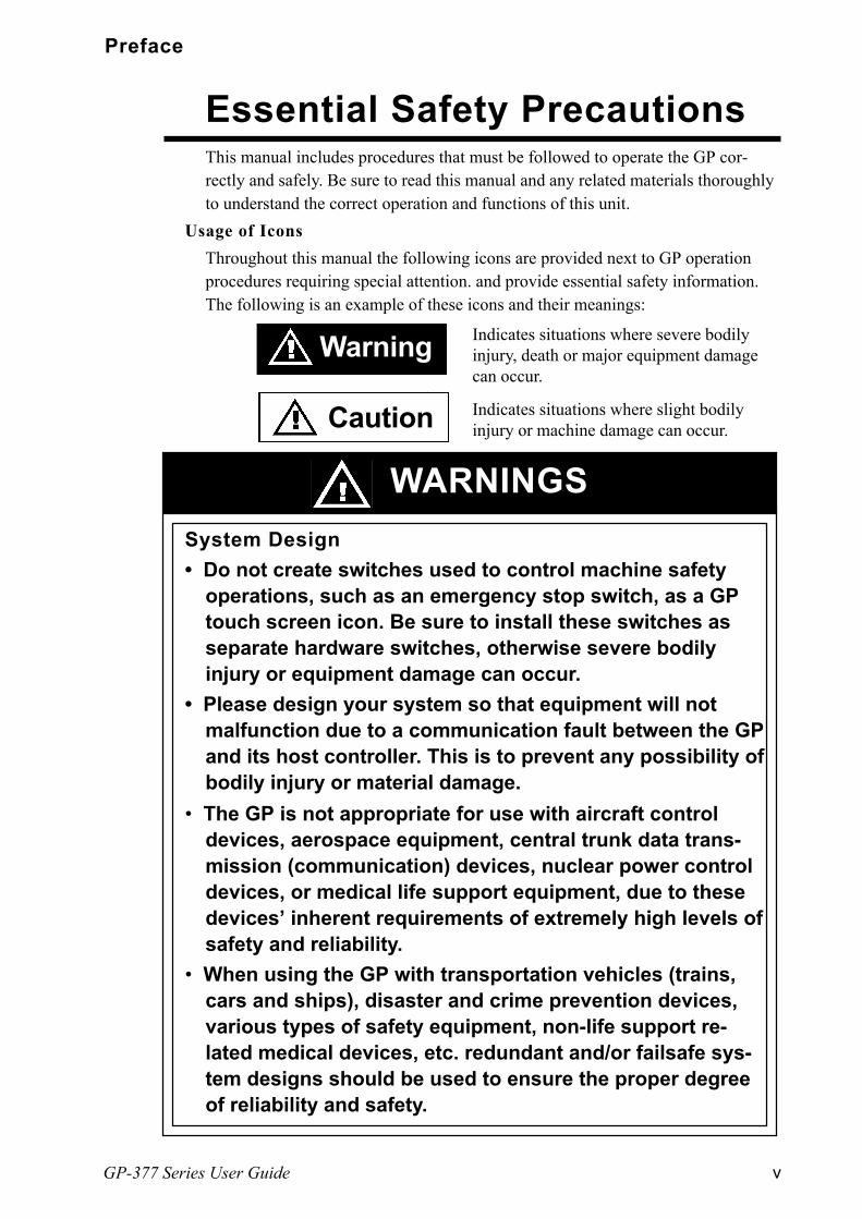
This manual includes procedures that must be followed to operate the GP cor-rectly and safely. Be sure to read this manual and any related materials thoroughlyto understand the correct operation and functions of this unit.
Usage of Icons
Throughout this manual the following icons are provided next to GP operationprocedures requiring special attention. and provide essential safety information.The following is an example of these icons and their meanings:
Indicates situations where severe bodilyinjury, death or major equipment damagecan occur.
Indicates situations where slight bodilyinjury or machine damage can occur.
System Design
Do not create switches used to control machine safetyoperations, such as an emergency stop switch, as a GPtouch screen icon. Be sure to install these switches asseparate hardware switches, otherwise severe bodilyinjury or equipment damage can occur.
Please design your system so that equipment will notmalfunction due to a communication fault between the GPand its host controller. This is to prevent any possibility ofbodily injury or material damage.
Essential Safety Precautions
Warning
WARNINGS
Caution
The GP is not appropriate for use with aircraft controldevices, aerospace equipment, central trunk data trans-mission (communication) devices, nuclear power controldevices, or medical life support equipment, due to thesedevices inherent requirements of extremely high levels ofsafety and reliability.
When using the GP with transportation vehicles (trains,cars and ships), disaster and crime prevention devices,various types of safety equipment, non-life support re-lated medical devices, etc. redundant and/or failsafe sys-tem designs should be used to ensure the proper degreeof reliability and safety.

vi GP-377 Series User Guide
Preface
GP Installation
High voltage runs through the GP. Except for replacingthe backlight, never disassemble the GP, otherwise anelectric shock can occur.
Do not modify the GP unit. Doing so may cause a fire oran electric shock.
Do not use the GP in an environment where flammablegasses are present, since operating the GP may cause anexplosion.
GP Wiring
To prevent an electric shock, be sure to confirm that theGP's power cord is not connected to the main powerwhen connecting any cords, cables or lines to the GP.
Do not use power beyond the GP's specified voltagerange. Doing so may cause a fire or an electric shock.
GP Start-up and Maintenance
The GP uses a lithium battery for backing up its internalclock data. If the battery is incorrectly replaced, the bat-tery may explode. To prevent this, please do not replacethe battery yourself. When the battery needs to be re-placed, please contact your local GP distributor.

viiGP-377 Series User Guide
Preface
GP Installation
Be sure to securely connect all cable connectors to theGP. A loose connection may cause incorrect input oroutput.
GP Wiring
Ground the GP's FG line separately from other units FGlines. Putting these FG lines too close may cause an elec-tric shock or unit malfunction. Be sure to use a groundingresistance of 100ΩΩΩΩΩ or less and a 2mm2 or thicker wire, oryour countrys applicable standard.
Correctly wire the GP, be sure that the rated voltage andterminal layout are within the designated range. If thevoltage supplied differs from the rated voltage, or incor-rect wiring or grounding is performed, it may cause a fireor unit malfunction.
Use only the designated torque to tighten the GP's termi-nal block screws. If these screws are not tightened firmly,it may cause a short-circuit, fire, or GP malfunction.
Be careful that metal filings and wiring debris do not fallinside the GP, since they can cause a fire, GP malfunc-tion, or incorrect operation.
GP Start-up and Maintenance
The liquid crystal panel contains a powerful irritant and iffor any reason the panel is damaged and this liquid con-tacts any part of your body, be sure to wash that area withrunning water for 15 minutes. If any of this liquid entersyour eye, flush your eye for 15 minutes with running waterand contact a physician.
GP Disposal
When this unit is disposed of, it should be done so ac-cording to your country's regulations for similar types ofindustrial waste.
CAUTIONS

viii GP-377 Series User Guide
Preface
General Safety Precautions
nnnnn To Prevent the GP From Being Damaged
Never strike the touch panel with a hard, heavy or pointed object, or press on the touchpanel too strongly, since it may damage the unit.
If the GP is used in an environment with temperatures and humidity in excess of theallowed range, the GP may malfunction and/or its operation life may be shortened.
Avoid restricting the GPs naturally occurring ventilation, or storing or using the GP in anenvironment that is too hot.
Do not use this unit in areas where large, sudden temperature changes can occur. Thesechanges can cause condensation to form inside the unit., possibly causing the unit tomalfunction.
Do not allow water, liquids, metal or charged particles to enter inside the GPs case, sincethey can cause either a GP malfunction or an electrical shock.
Avoid using or storing the GP in direct sunlight, or in excessively dusty or dirty environ-ments.
Because the GP is a precision instrument, do not store or use the unit where large shocksor excessive vibration can occur.
Do not store or use the GP where chemicals (such as organic solvents, etc.) and acids canevaporate, or where chemicals and acids are present in the air.
Do not use paint thinner or organic solvents to clean the GP. Do not store or operate the LCD display in areas receiving direct sunlight, since the suns
UV rays may cause the LCD displays quality to deteriorate. Storing this unit in areas at a temperature lower than is recommended in this manuals
specifications may cause the LCD displays liquid to congeal, which may damage thepanel. Conversely, if the storage areas temperature becomes higher than the allowedlevel, the LCDs liquid will become isotropic, causing irreversible damage to the LCD.Therefore, be sure to store the panel only in areas where temperatures are within thosespecified in this manual.
Due to the possibility of unforeseen accidents, be sure to back up theGPs screen data regularly.

ixGP-377 Series User Guide
Preface
nnnnnAbout the GP's Display Panel
The GP's currently displayed data, its voltage*1 and brightness setting eachaffect the intensity of Contouring. (i.e, when some parts of the screen arebrighter than others, creating a wavelike pattern)
There are minute grid-points (dark and light) on the Display Panel's surface.This is part of the GP's design and not a defect.
Shadows may appear at the top of the LCD. This is normal for an LCD display.
Sometimes the display area may look as if the display colors have changed.This is a common attribute of LCD's and is not a defect.
Displaying a single image for long periods can cause an afterimage to remainwhen the display is changed to another screen.
To prevent this effect:
Use the GP's "Stand-by Mode", which automatically turns the screen OFFwhen there is no input for a specified period of time.
5.3.1 System Setup
Write FFFFh in the System Data Areas Screen Display Off address *2 toturn the screen display OFF when there is no input for a specified period oftime.
Do not display any single screen for a long period of time. Try to periodi-cally change the screen display.
*1 If the GP's voltage is at the very low end of its allowable range, it may effect theintensitly of contouring.
*2 The following addresses assume all System Data Area settings are entered. If they arenot all entered, the correct word address may be different from those given here.
When using the Direct Access Method ------- System Data Areas word address +9
x GP-377 Series User Guide
Preface
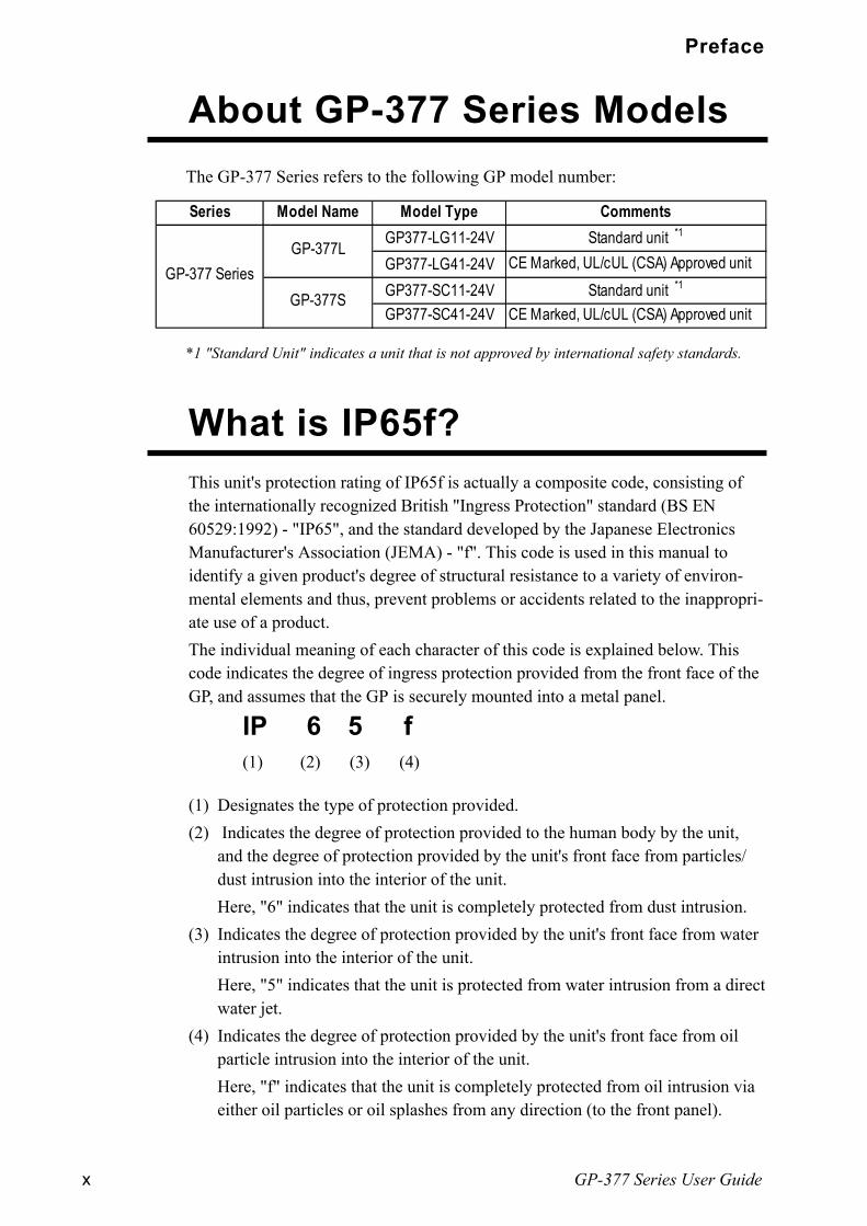
The GP-377 Series refers to the following GP model number:
About GP-377 Series Models
What is IP65f?This unit's protection rating of IP65f is actually a composite code, consisting ofthe internationally recognized British "Ingress Protection" standard (BS EN60529:1992) - "IP65", and the standard developed by the Japanese ElectronicsManufacturer's Association (JEMA) - "f". This code is used in this manual toidentify a given product's degree of structural resistance to a variety of environ-mental elements and thus, prevent problems or accidents related to the inappropri-ate use of a product.
The individual meaning of each character of this code is explained below. Thiscode indicates the degree of ingress protection provided from the front face of theGP, and assumes that the GP is securely mounted into a metal panel.
IP 6 5 f(1) (2) (3) (4)
(1) Designates the type of protection provided.
(2) Indicates the degree of protection provided to the human body by the unit,and the degree of protection provided by the unit's front face from particles/dust intrusion into the interior of the unit.
Here, "6" indicates that the unit is completely protected from dust intrusion.
(3) Indicates the degree of protection provided by the unit's front face from waterintrusion into the interior of the unit.
Here, "5" indicates that the unit is protected from water intrusion from a directwater jet.
(4) Indicates the degree of protection provided by the unit's front face from oilparticle intrusion into the interior of the unit.
Here, "f" indicates that the unit is completely protected from oil intrusion viaeither oil particles or oil splashes from any direction (to the front panel).
Series Model Name Model Type CommentsGP377-LG11-24V Standard unit *1
GP377-LG41-24V CE Marked, UL/cUL (CSA) Approved unitGP377-SC11-24V Standard unit *1
GP377-SC41-24V CE Marked, UL/cUL (CSA) Approved unit
GP-377 SeriesGP-377L
GP-377S
*1 "Standard Unit" indicates a unit that is not approved by international safety standards.

xiGP-377 Series User Guide
Preface
UL/c-UL(CSA) ApprovalThe GP377-LG41-24V, and the GP377-SC41-24V units are UL/c-UL listed products.
(UL file No.E182139)
This unit conforms to the following standards:
lllll UL508
Industrial Control Equipment
lllll UL1604
For use with Electrical Equipment in Class I and II, Division 2 and Class IIIHazardous (Classified) Locations in industrial control applications.
CAN/CSA-C22.2, Nos. 142 and 213-M1987
Standard for Safety of Information Technology Equipment, including Electrical Business Equipment.
GP377-LG41-24V (UL Registration Model: 2880011-02)
GP377-SC41-24V (UL Registration Model: 2880011-01)
<Cautions>
The GP must be used as a built-in component of an end-use product.
This unit should be installed in the front face of a metal panel.
If this unit is installed so as to cool itself naturally, be sure to install it in a verticalpanel. Also, be sure that the GP is mounted at least 100 mm away from any adja-cent structures or equipment. If these requirements are not met, the heat generatedby the GP's internal components may cause the unit to fail to meet UL/cUL stan-
dard requirements.
UL1604 Conditions of Acceptability and Handling Cautions:
1. Power, input and output (I/O) wiring must be in accordance with Class I, Division2 wiring methods - Article 501- 4(b) of the National Electrical Code, NFPA 70within the United States, and in accordance with Section 18-152 of the CanadianElectrical Code for units installed within Canada.
2. Suitable for use in Class I, Division 2, Groups A, B, C and D, Hazardous Locations.3. WARNING: Explosion hazard - substitution of components may impair suitabil-
ity for Class I, Division 2.4. WARNING: Explosion hazard - when in hazardous locations, turn power OFF
before replacing or wiring modules.5. WARNING: Explosion hazard - do not disconnect equipment unless power has
been switched OFF, or the area is known to be non-hazardous.
CE Marking
The GP377-LG41-24V, and GP377-SC41-24V are CE marked products that con-
forms to EMC directives EN55011 class A and EN50082-2.
* For detailed CE marking information, please contact your local GP distributor.

xii GP-377 Series User Guide
Preface
The GP's packing box contains the items listed below. Please check to confirmthat all items shown below have been included.
Package Contents
n n n n n GP-377 Series User Guide (1)
This guide (GP-377 Series User Guide) is sold separately.
nnnnn Installation Fasteners (4/set)
nnnnn Installation Guide (1)
This unit has been carefully packed, with special attention to quality. However,should you find anything damaged or missing, please contact your local GPdistributor immediately for prompt service.
Separately Sold Guide
nnnnn GP Units GP377-LG11-24V, GP377-LG41-24V GP377-SC11-24V, GP377-SC41-24V
GP-377 SeriesUser Guide
InstallationGuide
GP-377
Series Unit
xiiiGP-377 Series User Guide
Preface
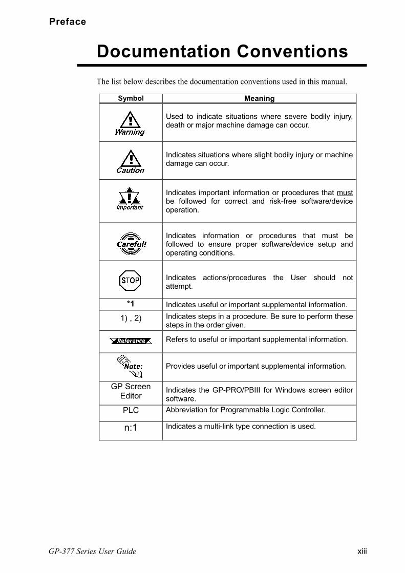
The list below describes the documentation conventions used in this manual.
Documentation Conventions
Symbol Meaning
Used to indicate situations where severe bodily injury,death or major machine damage can occur.
Indicates situations where slight bodily injury or machinedamage can occur.
Indicates important information or procedures that mustbe followed for correct and risk-free software/deviceoperation.
Indicates information or procedures that must befollowed to ensure proper software/device setup andoperating conditions.
Indicates actions/procedures the User should notattempt.
*1 Indicates useful or important supplemental information.
1) , 2) Indicates steps in a procedure. Be sure to perform thesesteps in the order given.
Refers to useful or important supplemental information.
Provides useful or important supplemental information.
GP ScreenEditor
Indicates the GP-PRO/PBIII for Windows screen editorsoftware.
PLC Abbreviation for Programmable Logic Controller.
n:1 Indicates a multi-link type connection is used.

xiv GP-377 Series User Guide
Preface
Memo
GP-377 Series User Guide 1-1
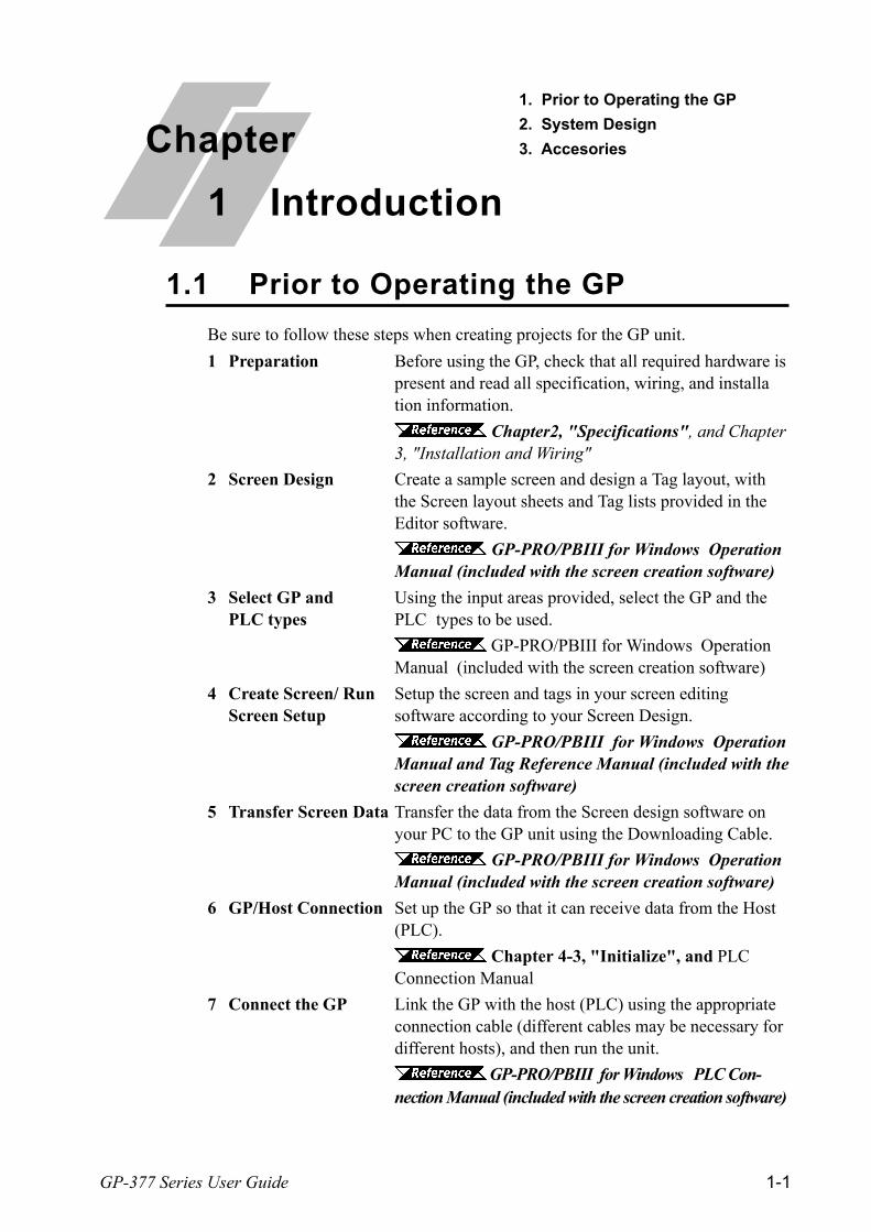
Be sure to follow these steps when creating projects for the GP unit.
1 Preparation Before using the GP, check that all required hardware ispresent and read all specification, wiring, and installation information.
Chapter2, "Specifications", and Chapter3, "Installation and Wiring"
2 Screen Design Create a sample screen and design a Tag layout, withthe Screen layout sheets and Tag lists provided in theEditor software.
GP-PRO/PBIII for Windows OperationManual (included with the screen creation software)
3 Select GP and Using the input areas provided, select the GP and thePLC types PLC types to be used.
GP-PRO/PBIII for Windows OperationManual (included with the screen creation software)
4 Create Screen/ Run Setup the screen and tags in your screen editingScreen Setup software according to your Screen Design.
GP-PRO/PBIII for Windows OperationManual and Tag Reference Manual (included with thescreen creation software)
5 Transfer Screen Data Transfer the data from the Screen design software onyour PC to the GP unit using the Downloading Cable.
GP-PRO/PBIII for Windows OperationManual (included with the screen creation software)
6 GP/Host Connection Set up the GP so that it can receive data from the Host(PLC).
Chapter 4-3, "Initialize", and PLCConnection Manual
7 Connect the GP Link the GP with the host (PLC) using the appropriateconnection cable (different cables may be necessary fordifferent hosts), and then run the unit.
GP-PRO/PBIII for Windows PLC Con-nection Manual (included with the screen creation software)
1.1 Prior to Operating the GP
Chapter
1 Introduction
1. Prior to Operating the GP
2. System Design
3. Accesories

Chapter 1 - Introduction
GP-377 Series User Guide1-2
1.2 System Design
Printer(Commercially availabletype)
Bar Code Reader
(Recommended Units*3)
RS-232C Cable*4
GP410-IS00-O
RS-422 Cable *4
GP230-IS11-OGP230-IS12-O (for Multi-link cable)
RS-422 ConnectorTerminal Adapter*4
GP070-CN10-O
Mitsubishi PLC FX-SeriesProgram Port I/F CableGP430-IP11-O
Mitsubishi PLC A-SeriesProgram Port I/F CableGP430-IP10-O
Host Controller
PersonalComputer *1
GP screencreation software
Data Transfer CableGPW-CB02
Memory Loader IIGP070-LD01-O(Rev.H or later)
Mitsubishi PLC A,QnA, FX Series'2 Port Adaptor IIGP070-MD11
PLC etc.
2 Port Adaptor IICableGP070-MDCB11
GP377-LG11-24V, GP377-LG41-24VGP377-SC11-24V, GP377-SC41-24V
Mitsubishi's GPP
feature software*2
GP Unit
GP Interfaces PLC Interfaces
Tool Connector RS-232C Port Serial Interface RS-422 Port
Programming PortPersonal Computer Interfaces
Printer Interface
Screen Editing Environment
GP Operating Environment

Chapter 1 - Introduction
GP-377 Series User Guide 1-3
AimexCorporation
BR-331 PC2(Pen type)
ReadingWidth
Touch ScannerType
KeyboardConnection Type
ReadingWidth
Touch ScannerType
60mm OPT-1125-WL 98 OPT-1125-WD 98 65mm TCD-5510M
80mm OPT-5125-WL 98 OPT-5125-WD 98 82mm TCD-5510L
100mm LT-2125-WL 98 LT-2125-WD 98 105mm TCD-5510W
TohkenOPT Electronics
*1 For range of compatible PCs refer to the following manual.
GP-PRO/PBIII for Windows Operation Manual (included with thescreen creation software)
*2 For information about compatible PLC types and software, please refer to
GP-PRO/PBIII for Windows PLC Connection Manual (included withthe screen creation software)
*3 Recommended Units:
*4 Certain types and models of PLCs cannot be connected.
GP-PRO/PBIII for Windows PLC Connection Manual (includedwith the screen creation software)

Chapter 1 - Introduction
GP-377 Series User Guide1-4
All optional equipment listed below is produced by Digital.
*1 For detailed information about range of connectable PLCs.
GP-PRO/PBIII for Windows PLC Connection Manual (includedwith the screen creation software)
nnnnn Available Software
nnnnn Tool Connector
nnnnn Serial InterfaceProduct Name Model No. Description
RS-232C cable *1 GP410-IS00-O
RS-422 cable *1 GP230-IS11-OGP230-IS12-O(for Multi-link)
RS-422 cableConnector terminalblock conversion
GP070-CN10-O Conversion adapter to convert serial datato RS-422 format.
2 Port Adapter II GP070-MD11 Interface unit that allows use of both GPand Mitsubishi A,Q, C and FX seriesequipment in the same location.
2 Port Adapter II Cable GP070-MDCB11 Connects the GP to 2 Port Adapter II.Mitsubishi A SeriesProgramming Port I/Fcable
GP430-IP10-O
Mitsubishi FX SeriesProgramming Port I/Fcable
GP430-IP11-O
Interface cable between the host (PLC)and GP.
Connects directly to Mitsubishi's PLC I/FProgramming Console. Simultaneoususe of program console, however, is notpossible.
1.3 Accessories
Product Name Model No. Description
Screen DataTransfer Cable
GPW-CB02 Connects the GP to a personal computer.Transfers screen data and userprogram(s).
Memory Loader II GP070-LD01-O Copies data (system and screen data) fromone GP to another GP. Rev. H or later
Product Name Model No. DescriptionGP-PRO/PB III forWindows Ver.4.0or later
GPW-PB01M-V40 <CD-ROM> Software to be used to create the GP'sscreen data using a personal computer.

Chapter 1 - Introduction
GP-377 Series User Guide 1-5
Product Name Model No. DescriptionScreen Protection Sheet Soft type: GP370-COVER-20P
Hard type: GP370-DF10-0Disposable protective and dirt-resistant sheet for the GP's screen.The GP's touch panel can be usedwith this cover sheet attached.
Screen Protection Cover GP370-DC11 A silicon gum cover which protectsGP's screen from condensation andchemicals.
nnnnn Options
nnnnn Optional Maintenance Items
These optional items were included in either the GP itself or in its packing box.These items are sold separately as optional maintenance items.
Product Name Model No. DescriptionBacklight GP377L/S-BL00-MS Spare Backlight
Installation fastener GP070-AT00-MS Fasteners to attach the GP to a panel.
Moisture resistantgasket
GP370-WP10-MS Provides a moisture resistant seal wheninstalling the GP. Same as the sealincluded in the GP's original equipmentpackage.

Chapter 1 - Introduction
GP-377 Series User Guide1-6
You can now use Mitsubishis GPP software (ladder programming software) onyour PC while you connect the Mitsubishi PLC to the GP and the GP to your PC.You can send ladder logic data to and from the PLC, via the GPs Internal 2 port-feature.With the GP377 Series unit, you can use the 2-Port feature by simplyconnecting the GP and your PC via the data transfer cable (GPW-CB02) withoutusing the external 2-Port Adapter.
GP
Digital's 2-Port Adapter II (GP070-MD11)
For information about PLC types and GP compatibility with GP-377 Series units,refer to GP-PRO/PBIII for Windows PLC Connection Manual (in-cluded with the GP screen creation software)
n n n n n When Using GP-377 Series units Internal 2-Port feature *1
Connected to the Serial I/F via
the Programmer I/F Cable
Connect to the tool connector via Data
Transfer Cable (GPW-CB02)
Connect to Programmer Port
PC with Mitsubishis GPP soft-
ware installed
Mitsubishi PLC( c o m p a t i b l etypes only)
GP
Connected to GPs Serial I/F
n n n n n When Using the External 2-Port Adapter Cable *2
PC with Mitsubishis GPP software installed, or
a Programming Console
or
Connect to Programmer Port
*1 The Device Monitor feature can also be used at the same time. For details about the devicemonitor function, refer to GP-PRO/PBIII for Windows PLC Connec-tion Manual (included with the GP screen creation software)
*2 GP-377 Series units can also use the 2-Port Adapter II.
1.4 2-Port Feature Overview
Mitsubishi PLC( c o m p a t i b l etypes only)

Chapter 1 - Introduction
GP-377 Series User Guide 1-7
n n n n n Internal 2-Port Feature Usage Notes
To use the Internal 2-Port feature, you will need to adjust your GPs settings.For information about these settings, refer to GP-PRO/PBIIIfor Windows PLC Connection Manual (included with the GP Screen creationsoftware)
This feature can be used only while the GP is in ONLINE mode.
Since the internal 2-Port feature uses the GPs single tool connector, you willnot be able to use optional equipment which requires the tool connector (i.e. aBarcode Reader, etc.)
If you transfer screen data while the GP is in ONLINE mode, the screenwill not change to the data transfer screen automatically. Thus, you willneed to change the screen manually to the OFFLINE mode's [Main Menu/Transfer] screen. 4.5 Transferring Screen Data
Peripheral equipment which cannot be connected to the GP's tool connector(such as a Programming Console) is not compatible with the GP's Internal 2-Port feature. To use this type of equipment, you will need to use the external 2-Port Adapter II.

Memo

GP-377 Series User Guide 2-1
Input Voltage DC24V+15%
Power Consumption 20W or less
Allowable Voltage Drop 2ms or less
Voltage EnduranceAC1000V 10mA for 1 minute
(between charging and FG terminals)
Insulation Resistance 20MΩ or higher at DC500V(between charging and FG terminals)
2.1.1 Electrical
2.1.2 Structural
2.1 General Specifications
Chapter
2 Specifications
4. Names and Functions of GP Parts
5. Graphic Panel Dimensions
1. General Specifications
2. Functional Specifications
3. Interface Specifications
*1 See note on following page.
Ratings(For front face of installed unit)
Equivalent to IP65f (JEM1030) and NEMA #250 TYPE 4X/12
Weight900g (2.0lb) or less
(main unit only)
Cooling Method Natural air circulation
External Dimensions171mm (6.73in.) <W> x 138mm (5.43in.) <H>
x 57mm (2.24in.) <D> (main unit only)
156 X 123.5 mm(Panel thickness: 1.6 to 5mm)
Panel Cut Dimensions+10
+10

Chapter 2 - Specifications
GP-377 Series User Guide2-2
*1 The front face of the GP unit, installed in a solid panel, has been tested using condi-tions equivalent to the standard shown in the specification . Even though the GPunits level of resistance is equivalent to the standard, oils that should have no effecton the GP can possibly harm the unit. This can occur in areas where either vaporizedoils are present, or where low viscosity cutting oils are allowed to adhere to the unitfor long periods of time. If the GPs front face protection sheet becomes peeled off,these conditions can lead to the ingress of oil into the GP and separate protectionmeasures are suggested. Also, if non-approved oils are present, it may cause deforma-tion or corrosion of the front panels plastic cover. Therefore, prior to installing theGP be sure to confirm the type of conditions that will be present in the GPs operatingenvironment.
If the installation gasket is used for a long period of time, or if the unit and its gasketare removed from the panel, the original level of the protection cannot be guaranteed.To maintain the original protection level, you need to replace the installation gasketregularly.
2.1.3 Environmental
Ambient OperatingTemperature
0oC to +50oC
Storage Temperature -20oC to +60oCAmbient Humidity 20%RH to 85%RH (No condensation)
Vibration Resistance 10Hz to 25Hz (19.6m/s2 in X, Y, Z directions for 30min.)Noise Voltage: 1000Vp-p
Pulse Duration: 1µsArise T ime: 1ns
Electrostatic DischargeImmunity
GP377-**11-24V: 4kV (complies with IEC 61000-4-2 Level 2)GP377-**41-24V: 6kV (complies with IEC 61000-4-2 Level 3)
Atmosphere Less than 0.1mg/m3 of conductive dust, free of corrosive gassesGrounding 100Ω or less, or your country's applicable standard
Noise Immunity(via noise simulator)
(from previous page)
Chapter 2 - Specifications
GP-377 Series User Guide 2-3
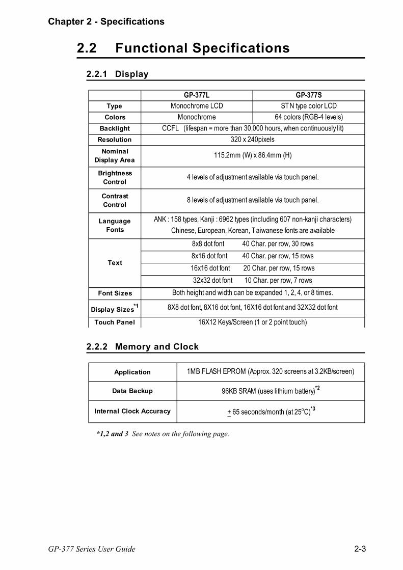
GP-377L GP-377SType Monochrome LCD STN type color LCD
Colors Monochrome 64 colors (RGB-4 levels)Backlight
Resolution
8x16 dot font 40 Char. per row, 15 rows16x16 dot font 20 Char. per row, 15 rows32x32 dot font 10 Char. per row, 7 rows
NominalDisplay Area
CCFL (lifespan = more than 30,000 hours, when continuously lit)320 x 240pixels
115.2mm (W) x 86.4mm (H)
Touch Panel 16X12 Keys/Screen (1 or 2 point touch)
8X8 dot font, 8X16 dot font, 16X16 dot font and 32X32 dot fontDisplay Sizes*1
Font Sizes
Text
ANK : 158 types, Kanji : 6962 types (including 607 non-kanji characters)Chinese, European, Korean, Taiwanese fonts are available
4 levels of adjustment available via touch panel.
8 levels of adjustment available via touch panel.
Both height and width can be expanded 1, 2, 4, or 8 times.
BrightnessControl
LanguageFonts
ContrastControl
8x8 dot font 40 Char. per row, 30 rows
2.2 Functional Specifications
2.2.1 Display
Application 1MB FLASH EPROM (Approx. 320 screens at 3.2KB/screen)
Data Backup 96KB SRAM (uses lithium battery)*2
Internal Clock Accuracy + 65 seconds/month (at 25oC)*3
2.2.2 Memory and Clock
*1,2 and 3 See notes on the following page.

Chapter 2 - Specifications
GP-377 Series User Guide2-4
Asynchronous Transmission Method:RS232C/RS422Data Length: 7 or 8 bitsStop Bit: 1 or 2 bitsParity: None, Odd or EvenData Transmission Speed: 2400 to 115.2kbpsAsynchronous TTL level nonprocedure command I/F<During Program Development>For connecting the Data Transfer cable when downloading data from the GP-PRO/PBIII screen editor software.<During Standard Operation>When using the 2-Port function, and for connecting peripheral equipment,i.e. a bar code reader, etc.
Tool Connector
Serial Interface
*1 The display font will differ depending on which (country's) character, or which
size you select. For detailed information refer to Chapter 5.9 FontSetting.
*2 A Lithium battery's lifetime is:
10 years when the battery's ambient temperature is under 40 oC
4.1 years when the battery's ambient temperature is under 50 oC
1.5 years when the battery's ambient temperature is under 60 oC
When used for backup:
Approximately 60 days, with a fully charged battery
Approximately 6 days, with a half-charged battery
*3 The GP's internal clock has a slight error. At normal operating temperaturesand with the GP's power turned OFF, i.e. in "backup mode", the degree oferror is 65 seconds per month. Variations in operating conditions and batterylife can cause this error to vary from +90 to -380 seconds per month.For systems where this degree of error will be a problem, the user should besure to monitor this error and make adjustments when required.
2.2.3 Interfaces

Chapter 2 - Specifications
GP-377 Series User Guide 2-5
*1 #12 and #13 are RESERVED; do not connect to these pins.
2.3 Interface Specifications2.3.1 Serial Interface
Recommended Connector: Dsub25pin plug XM2A-2501<made by OMRON>
Recommended Cover: Dsub25pin cover XM2S-2511<made by OMRON>
Jack Screws: XM2Z-0071<made by OMRON>
• Use rough metric type M2.6x0.45 p threads used to secure the cable's set screws.
Recommended Cable: CO-MA-VV-SB5PX 28AWG <made by HITACHI Cable Ltd.>
• To confirm your PLC's connection specifications
PLC Connection Manual (included with the screen creation software)
1
13
25
14
Pin Connection Pin # Signal Name Condition
1 FG Frame ground
2 SD Send data (RS-232C)
3 RD Receive data (RS-232C)
SIO 4 RS Request send (RS-232C)
5 CS Clear send (RS-232C)
6 NC No connection
7 SG Signal ground
8 CD Carrier detect (RS-232C)
9 TRMX Termination (RS-422)
10 RDA Receive data A (RS-422)
11 SDA Send data A (RS-422)
12 *1 RESERVE Reserved
13 *1 RESERVE Reserved
14 VCC 5V±5% output 0.25A
15 SDB Send data B (RS-422)
16 RDB Receive data B (RS-422)
17 NC No connection
18 CSB Clear send B (RS-422)
19 ERB Enable receive B (RS-422)
20 ER Enable receive (RS-232C)
21 CSA Clear send A (RS-422)
22 ERA Enable receive A (RS-422)
23 BUZZ GND External buzzer ground
24 NC No connection
25 BUZZ OUT External buzzer output
Chapter 2 - Specifications
GP-377 Series User Guide2-6
When creating your own cable, follow the instructions listed below:
<With RS-422>
The following pairs of pin #'s must be connected to each other.
#18 (CSB) <> #19 (ERB)
#21 (CSA) <> #22 (ERA)
When connecting the RS-422 cable and the #9 (TRMX) and #10 (RDA) points, atermination resistance of 100ΩΩΩΩΩ is added between RDA and RDB.
When making a cable for a Memory Link system, be sure to use a 4-wire type.
<With RS-232C> Do not use the following pins: 9 (TRMX), 10 (RDA), 11 (SDA), 15 (SDB), 16
(RDB), 18 (CSB), 19 (ERB), 21 (CSA), 22 (ERA).
The #1 (FG) terminal should only be connected if it is required by the device beingconnected to.
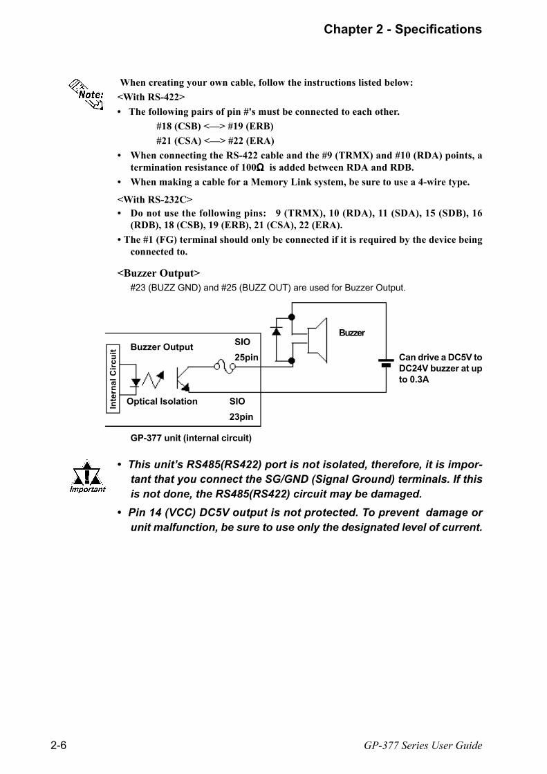
<Buzzer Output>#23 (BUZZ GND) and #25 (BUZZ OUT) are used for Buzzer Output.
Optical Isolation
BuzzerSIO
25pin
SIO
23pin
GP-377 unit (internal circuit)
Inte
rna
l C
irc
uit Buzzer Output
This units RS485(RS422) port is not isolated, therefore, it is impor-tant that you connect the SG/GND (Signal Ground) terminals. If thisis not done, the RS485(RS422) circuit may be damaged.
Pin 14 (VCC) DC5V output is not protected. To prevent damage orunit malfunction, be sure to use only the designated level of current.
Can drive a DC5V toDC24V buzzer at upto 0.3A

Chapter 2 - Specifications
GP-377 Series User Guide 2-7
A:Display Panel
The GP monitor screen displays the screensetup and corresponding PLC host data.
GP-377L Monochrome LCD
GP-377S STN type Color LCD
B: Touch Panel
Performs any screen change operations andsends data to the PLC.
C: Status LED
This LED reflects the GP's condition.
D: Power Input Terminal Block
The input and ground terminals for thepower cable.
E: Expansion Interface
Used for expansion boards.
F: Serial Interface
Used for the RS-232C and RS-422 (Serial)cables. Is connected to the Host (PLC).
G:Tool Connector
The Data Transfer cable, Bar Code Readeror Memory Loader can be connected here.
LED GP status
OFF Power OFF
Green Normal operation
Orange Replace backlight
A,BC
D E
F
G
2.4 Names and Functions of GP Parts

Chapter 2 - Specifications
GP-377 Series User Guide2-8
Unit: mm (in.) Top View
155.5 (6.12)
Front View Side View171 (6.73) 57 (2.24)
Rear View
For detailed dimension information, please contact your local GP distributor.
2.5 GP Dimensions
2.5.1 GP External Dimensions
12
3 (
4.8
4)
5 (0.2)
13
8 (
5.4
3)

Chapter 2 - Specifications
GP-377 Series User Guide 2-9
4-R3 or less156 (6.14 )+0.04 0
+10
(4.8
4
)
+0.
04 0
12
3.5
+1
0
2.5.2 GP Installation Fasteners
2.5.3 GP Panel-Cut Dimensions
Unit: mm (in.)
Top View
Rear View
Front View Side View
Unit: mm (in.)

Memo

GP-377 Series Users Manual 3-1
Chapter
3 Installation and Wiring
1. Installation
2. Wiring Cautions
3. GP Tool Connector
Decide the panels thickness based on the level of panel strengthrequired.
Before installing the GP into a cabinet or panel, check that the installa-tion gasket is securely attached to the unit.
3.1 Installation
3.1.1 Installation Procedure
nnnnn Creating a Panel Cut Out
It is strongly recommended that you use the gasket since itabsorbs vibration in addition to repelling water.
Place the PL on a level surface with the display panel facingdownward. Check that the GPs installation gasket is seatedsecurely into the gaskets groove, which runs around theperimeter of the panels frame. For details about installingthe gasket, refer to
7.1.2 Installation Gasket Replacement
Create the correct sized opening required to install the GP, using the installationdimensions given.
2.5.3 GP Panel Cut Out Dimensions
The installation gasket, installation brackets and attachment screws are all re-quired when installing the GP.
Installation gasketRear of GP
Cut OutArea
Panel
1.6mm(0.06in.) to 5mm(0.2in.)
Check that the installation panel or cabinet's surface is flat, in good condition andhas no jagged edges.
Panel thickness should be from 1.6mm (0.06in.) to 5.0mm (0.2in.).
GP-377 Series Users Manual 3-2
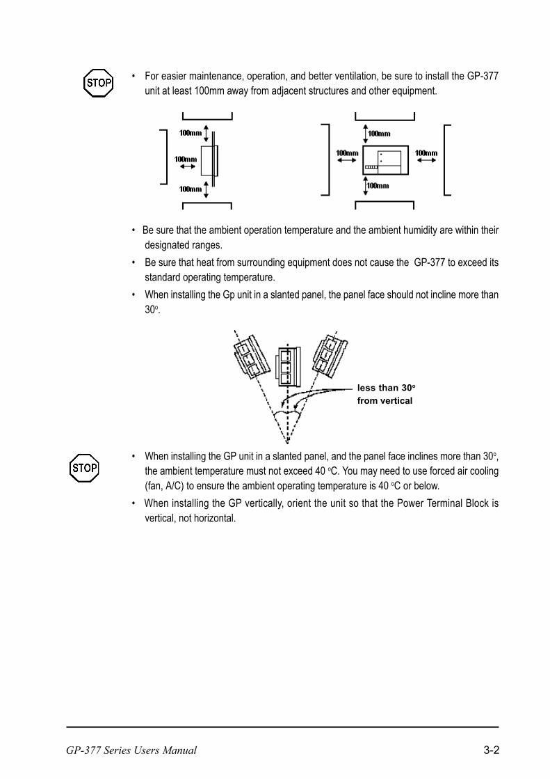
For easier maintenance, operation, and better ventilation, be sure to install the GP-377unit at least 100mm away from adjacent structures and other equipment.
less than 30o
from vertical
Be sure that the ambient operation temperature and the ambient humidity are within theirdesignated ranges.
Be sure that heat from surrounding equipment does not cause the GP-377 to exceed itsstandard operating temperature.
When installing the Gp unit in a slanted panel, the panel face should not incline more than30o.
When installing the GP unit in a slanted panel, and the panel face inclines more than 30o,the ambient temperature must not exceed 40 oC. You may need to use forced air cooling(fan, A/C) to ensure the ambient operating temperature is 40 oC or below.
When installing the GP vertically, orient the unit so that the Power Terminal Block isvertical, not horizontal.
GP-377 Series Users Manual 3-3
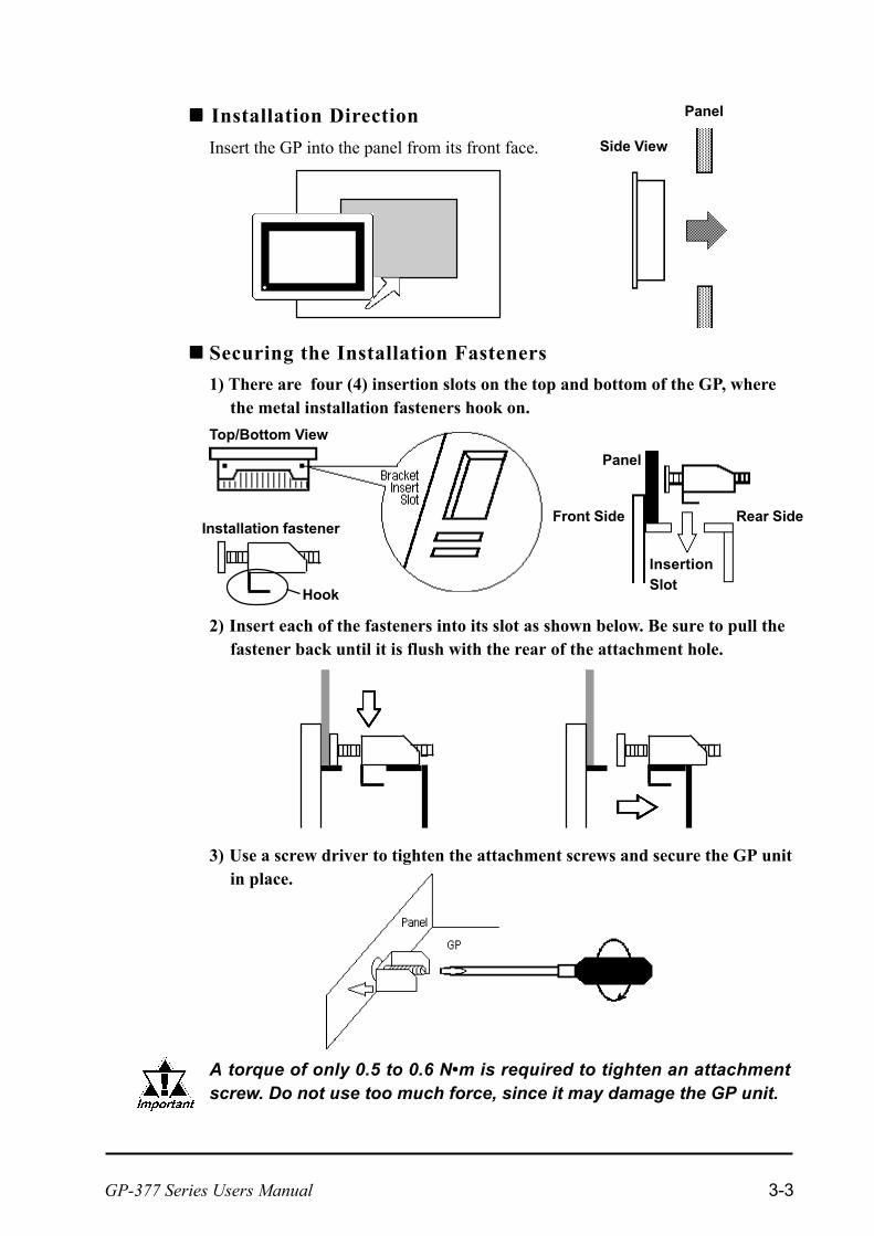
1) There are four (4) insertion slots on the top and bottom of the GP, wherethe metal installation fasteners hook on.
Top/Bottom View
3) Use a screw driver to tighten the attachment screws and secure the GP unitin place.
A torque of only 0.5 to 0.6 Nm is required to tighten an attachmentscrew. Do not use too much force, since it may damage the GP unit.
2) Insert each of the fasteners into its slot as shown below. Be sure to pull thefastener back until it is flush with the rear of the attachment hole.
nnnnn Installation Direction
nnnnn Securing the Installation Fasteners
Side View
Panel
Installation fastener
Hook
Panel
Front Side Rear Side
InsertionSlot
Insert the GP into the panel from its front face.

GP-377 Series Users Manual 3-4
Wherever possible, use thick wires (max 2mm2) for power terminals, and twist theexposed wire ends when connecting the Ring Terminals.
Please use the following size Ring Terminals.
To prevent the Ring Terminals from causing a short when the terminal blockattachment screws are loosened, be sure to use sleeve-type Ring Terminals.
3.2 Wiring Cautions
3.2.1 Connecting the GP's Power Cord
When the FG terminal is connected, be sure the wire is grounded. Notgrounding the GP unit will result in excessive noise.
lllll Connect the GP Power Supply Terminals as follows:
1) Be sure that the GP's Power Cord is not plugged in to the power supply.2) Remove the Terminal Strip's clear plastic cover.3) Remove the screws from the three (3) middle terminals, position the Ring
Terminals as shown above and re-attach the screws. (Check each wire to makesure the connections are correct)
4) Re-attach the Terminal Strip's clear plastic cover.
A torque of only 0.5 to 0.6 Nm is required to tighten an attachment screw.
over Ø3.2mm
under 6.0mm
Crimp-on Ring
Terminals+ - FG
Power Terminal Block
Rear of GP-377
FG
+
-
To avoid electric shocks, be sure the Power Cord is un-plugged from the power outlet when connecting thepower terminals to the GP unit.
GP-377 Series units accept DC 24V power input only. Us-ing an incorrect power supply will result in damage toboth the power supply and the GP.
Re-attach the GP Terminal Strips clear plastic cover aftercompleting wiring. If the Cover is not installed, it maycause an electric shock.
WARNINGS

GP-377 Series Users Manual 3-5
Do not use common grounding, since it can lead to anaccident or machine malfunction.
3.2.2 Grounding the GP
(a) Exclusive Grounding (BEST) *1 Connect the FG terminal found atthe back of the unit to an exclusiveground. [diagram (a)].
CAUTION
(b) Common Grounding (OK)*1
Check that the grounding re-sistance is less than 100ΩΩΩΩΩ.
The grounding wire shouldhave a cross sectional areagreater than 2mm2. Set theconnection point as close tothe GP unit, and make thewire as short, as possible.When using a long groundingwire, replace the thin wirewith a thicker wire, placed ina duct.
(c) Common Grounding (Not OK)
Input and output signal lines must be separated from the power control cablesfor operating circuits.
If this is not possible, use a shielded cable and connect the shield to the GP'sframe.
3.2.3 Placement of I/O Signal Lines
If exclusive grounding is not pos-sible, use a common connectionpoint. [diagram (b)]
If the equipment does not functionproperly when grounded, disconnectthe ground wire from the FG termi-nal.
*1 Use a grounding resistance of less than 100Ω and a 2mm2 or greater thickness wire,or your countrys applicable standard. For details, contact your local GP distributor.

GP-377 Series Users Manual 3-6
3.3 GP Tool Connector
Tool Connector
The GP's Data Transfer Cable, Memory Loader, or the Bar Code Reader canbe attached to the GP's side face Tool Connector.
Before unplugging any connector(s) from the GP, be sure theGP's power cord is unplugged from the main power supply.
Do not connect or disconnect any equipment to or from theGPs Tool Connector while the GPs Power cord is connected.
When the Bar Code Reader uses a separate power supply:
- Turn the Bar Code Reader ON before turning the GP ON.
- Turn the GP OFF before turning the Bar Code Reader OFF.
GP Side view

Current Date/Time
Protocol Version Protocol Name
OFFLINE Mode provides access to the Initialize, Self-Diagnosis, and otherfeatures built into the GP. You will need to change the GP to OFFLINE modebefore you can use any of these features.
OFFLINE mode is unavailable in a completely new GP until the neces-sary Screen Data has been transfered from the screen editor software.Be sure the GP's power cord is plugged in and no images are displayedon the GP screen. When data is transferred from your PC to the GP, thenecessary System Data will be sent.
To INITIALIZE the setup or run SELF-DIAGNOSIS in the GP unit, transferringto the OFFLINE mode becomes necessary. There are two ways to enter OFFLINEmode. First, immediately after plugging in the GP's power cord, and second, byusing the Force Reset feature.
For information about transferring data to the GP, refer to GP-PRO/PBIII for Windows Operation Manual (included with the screen cre-ation software)
4.1 Entering OFFLINE Mode
Chapter
4 OFFLINE Mode
1. Entering OFFLINE Mode
2. OFFLINE Modes Main Menu
3. INITIALIZATION
4. SELF-DIAGNOSIS
5. Transferring Screen Data
Touch the upper left-hand corner of the GP screen within 10 seconds of pluggingin the GP's power cord.
4.1.1 When Turning the GP's Power ON

GP-377 Series Users Manual4-2
Chapter 4 - Installation and Wiring
When the GP unit has the Device Monitor function, the following display will appear.
GP-PRO/PBIII for Windows PLC Connection Manual (included withthe screen creation software), Appendix 3 - Device Monitor
If a Password has been set in INITIALIZE/ SET UP SYSTEM, before entering theOFFLINE mode, the following screen appears.Enter the password, then touch Set to enter OFFLINE mode.
From the Forced Reset screen, touch the OFFLINE button and the Main Menuwill appear.
4.1.2 From Forced Reset
For instructions on how to enter the Forced Reset Screen 5.4.3 Set Up Touch Panel; FORCE RESET
For more information about Passwords, Chapter 5.3.1, "SYSTEMSETUP" and Chapter 4.3, "Initialize-Standard Operation

GP-377 Series Users Manual
Chapter 4 - Installation and Wiring
4-3
INITIALIZEThe setup items listed in this menu are necessary to run the GP unit.
TRANSFER SCREEN DATASelect to transfer screen data to and from the screen editing software.
SELF-DIAGNOSISChecks to see if there are any problems with the GP System or Interface (I/F).
RUNStarts GP operation.
For more information about INITIALIZE, refer to Chapter 5, "Initial-ization"; for more information about TRANSFER SCREEN DATA, referto GP-PRO/PBIII for Windows Operation Manual (included with thescreen creation software); for more information about SELF-DIAGNO-SIS and RUN, refer to Chapter 6, "GP Run Mode and Errors".
Select the desired menu item by touching the corresponding item bar on the screenselection.Each Main Menu item is used as follows.
4.2 OFFLINE Mode Main Menu
Each menu item shown below has different settings that must be set to match thecorresponding PLC in order for the GP to communicate properly.Entering OFFLINE mode calls up the following screen.

GP-377 Series Users Manual4-4
Chapter 4 - Installation and Wiring
nnnnn Selecting Setup Conditions
After selecting a menu item and entering that area, touch the option you wouldlike to setup. The selected item becomes highlighted. In this example, theTOUCH BUZZER SOUND has been set Off.
4.3 INITIALIZATION
nnnnn Selecting A Menu
Touch the menu item, or input field to select it.
nnnnn Entering Numbers
After selecting an input field by touching it, use the numeric touch keys located atthe bottom of the screen to enter numeric values. After inputting each value, touchthe [SET] key to define the value.

GP-377 Series Users Manual
Chapter 4 - Installation and Wiring
4-5
nnnnn After All Setting Data is Entered
Touch the top-right [SET] button.
If you wish to exit the screen without saving the changes, touch the CANCELbutton.
nnnnn Return To Previous Screen
Touch the title of the screen you would like to return to.
E.g. To return to the MAIN MENU from the SYS.ENVIRONMENT screen,simply touch the MAIN MENU title.
Press the [SET] key to write the Setupconditions onto the Internal FEPROM,which may take some time, causing adelay in returning to the previousscreen. Therefore, do not touch thescreen until the previous menu displayreturns.
Press the [SET] key to write the Setupconditions onto the Internal FEPROM,and Press the [CANCEL] key to notwrite the Setup conditions onto theInternal FEPROM and return to theprevious menu.

GP-377 Series Users Manual4-6
Chapter 4 - Installation and Wiring
nnnnn [SET], [CANCEL] Keys
After selecting the Self Diagnosis item, the [SET], and [CANCEL] keys mayappear at different times at the top of the screen.
lllll [CANCEL] Key
When this key is pressed, the selected Self-Diagnosis test is cancelled, and you arereturned to the SELF-DIAGNOSIS menu.
nnnnn Selecting a Sub-Display
Touch the desired the menu item and that sub-display will appear.
4.4 SELF-DIAGNOSIS
lllll [SET] Key
When this key is pressed, your selected Self-Diagnosis test begins.
GP-377 Series Users Manual
Chapter 4 - Installation and Wiring
4-7
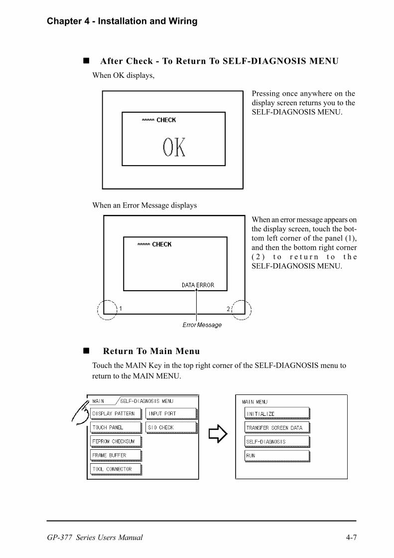
When an Error Message displays
nnnnn Return To Main Menu
Touch the MAIN Key in the top right corner of the SELF-DIAGNOSIS menu toreturn to the MAIN MENU.
nnnnn After Check - To Return To SELF-DIAGNOSIS MENU
When OK displays,
Pressing once anywhere on thedisplay screen returns you to theSELF-DIAGNOSIS MENU.
When an error message appears onthe display screen, touch the bot-tom left corner of the panel (1),and then the bottom right corner( 2 ) t o r e t u r n t o t h eSELF-DIAGNOSIS MENU.

GP-377 Series Users Manual4-8
Chapter 4 - Installation and Wiring
4.5 Transferring Screen Data
GP-377 unit (Side view)
This section describes the process required to transfer screen data to the GP, and toreceive data from the GP.
Connect the Data Transfer cable to the GP's tool connector, located on the sideface of the GP, and to the PC's serial port.
Tool Connector
When sending the Project file to the GP, the Data Transfer cable (GPW-CB02 - sold separately) is needed.
Also, please note that an I/F conversion adaptor is not included withthe GP. If this adaptor is necessary, it can be purchased at a computersupply store.
Desktop ornotebook
PC
To PC's serial port
Data Transfer Cable GP
To GP's tool connector
When using a serial mouse, be sure to use a different serial port for the data transfercable.
GP-377 Series Users Manual
Chapter 4 - Installation and Wiring
4-9
*1 Setup means to download the GPs system program and a PLC protocol driver from thescreen editor software, in order to run the GP in a desired environment.
Also, please remember that OFFLINE mode is unavailable in a completely newGP until the necessary Screen Data has been transfered from the screen editorsoftware.
Therefore, be sure the GP's power cord is plugged in and no images are displayedon the GP screen. While screen data is being sent from your PC to the GP, thenecessary System Data will be sent together with it.
GP-PRO/PBIII for Windows Operation Manual (included with thescreen creation software)
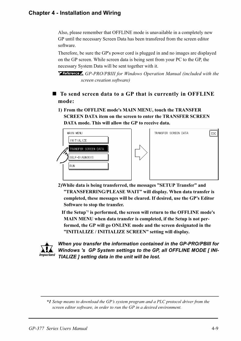
nnnnn To send screen data to a GP that is currently in OFFLINEmode:
1) From the OFFLINE mode's MAIN MENU, touch the TRANSFERSCREEN DATA item on the screen to enter the TRANSFER SCREENDATA mode. This will allow the GP to receive data.
2)While data is being transferred, the messages SETUP Transfer andTRANSFERRING/PLEASE WAIT will display. When data transfer iscompleted, these messages will be cleared. If desired, use the GPs EditorSoftware to stop the transfer.
If the Setup*1 is performed, the screen will return to the OFFLINE mode'sMAIN MENU when data transfer is completed, if the Setup is not per-formed, the GP will go ONLINE mode and the screen designated in theINITIALIZE / INITIALIZE SCREEN setting will display.
When you transfer the information contained in the GP-PRO/PBIII forWindows 's GP System settings to the GP, all OFFLINE MODE [ INI-TIALIZE ] setting data in the unit will be lost.

Memo

GP-377 Series Users Manual 5-1
*1 PLC's that support the n:1 (multi-link) connection are limited.
PLC Connection Manual (included with the screen creation software)
*2 Refer to GP screen creation software's "SYSTEM SETTINGS" area.
Occasionally, you may want to change your GP's general operation settings. Thesettings used for this are found in the INITIALIZE option in the GP OFFLINEmode's MAIN MENU.
This chapter explains each of the OFFLINE mode's INITIALIZE items. However,there are 2 types of INITIALIZE settings, those for the 1:1 connection and thosefor the n:1 (multi-link) connection*1.
The n:1 mark appears on original menu items concerned only with the n:1multi-link connection. If there is no mark, the menu item is common to both 1:1and n:1 connections.
1:1 Processing where a single (1) GP is connected with a single (1) PLC.
n:1 Processing where multiple GPs are connected with a single PLC. The GPssuccessively pass a PLC Access Token (exclusive PLC interaction key)among themselves to designate which unit can communicate with the PLC.
If you transfer your screen design software's System file *2, the GP operates using thatdata. If the GP System file has been correctly setup and transferred, the INITIAL-IZE settings become unnecessary. For more information about GP System files
Operation Manual, 1.1.2 "Screen Types" (included with the screencreation software)
5.1 Initialization Screen
Chapter
5 Initializing the GP
1. Initialization Screen
2. Initialization Items
3. SYSTEM ENVIRONMENT SETUP4. SET UP I/O
5. PLC SETUP
6. INITIALIZE INTERNAL MEMORY
7. SET UP TIME
8. SET UP SCREEN
9. FONT SETTING

Chapter 5 - Initializing the GP
GP-377 Series Users Manual5-2
The contents of the Initialize setup items listed below are explained in this Chap-ter. To learn about screen operations and numeric input.
1 SYSTEM ENVIRONMENT SETUP
System Settings
System Area SettingsGlobal Window Settings
Character String Data Settings
2 SET UP I/O
Set Up SIOCommunication Setup
Set Up I/O
DISPLAY SETUP
3 PLC SETUP MENU *1
Set Up Operation Surround-ings
Station Setup(n:1)
Customize Setup(n:1)
4 INITIALIZE MEMORY
5 SET UP TIME
6 SET UP SCREEN
7 FONT SETTING
Chapter 4, "OFFLINE Mode"
*1 Note that, depending on the PLC type selected, the screens that appear in your GPsscreen editor software will vary.
5.2 Initialization Items

Chapter 5 - Initializing the GP
GP-377 Series Users Manual 5-3
STAND-BY MODE TIME (0-255)To protect the GP display screen, the GP is equipped with a screen saver functionthat automatically turns the unit's backlight(s) OFF when no operations haveoccurred for a period of time. A "0" entered in this field causes a normal display,i.e. the screen is cleared after the GP's standard default time elapses.When SYSTEM DATA AREA's ( GP-PRO/PBIII for Windows PLCConnection Manual (included with the screen creation software) SCREEN DIS-PLAY OFF*1 data is 0000h, and the following operations are not performed on thescreen for the User's designated period of time, the GP's current display data iscleared.
Change Screen Touch Screen Alarm Display
START TIME (0-255)This setup determines the start-up time of the GP. Use this setup to adjust thepower up sequence so that the GP starts up after the PLC.
TOUCH BUZZER SOUNDSetup whether or not the GP beeps when pressed.
PASSWORD SETUP(0-9999)The password setting is used when changing to the Initialize Memory or Initialize(OFFLINE mode) Screens. The password (number) ensures protection of the GPsettings as OFFLINE mode will not be entered inadvertently. Enter the optionalnumber of your choice. If you do not wish to use this setup, enter the default 0.
*1 When using the Direct Access or the Memory Link formats, the object addressbecomes +9 or +12, respectively. (Only when all items are set within the System DataArea.)
GP-PRO/PBIII for Windows PLC Connection Manual (included with
GP environment adjustments are made here. The SYSTEM ENVIRONMENTSETUP includes the SYSTEM SETUP, SYSTEM DATA AREA, GLOBALWINDOW SETUP, and CHARACTER STRING DATA SETUP.
5.3 SYSTEM ENVIRONMENT SETUP
5.3.1 SYSTEM SETUP

Chapter 5 - Initializing the GP
GP-377 Series Users Manual5-4
Here you can designate the settings for the System Data Area. The System DataArea is allocated in the PLCs internal memory, and is used for controlling the GP.Devices that can be set in this area will differ depending on the PLC type.
When using the Memory Link format, this setting is unnecessary.
PLC Connection Manual (included with the screen creation software)
Press the item, and when the item is highlighted, it has been selected.
DATA TYPE OF SCREEN NO.This setup controls whether BIN or BCD format numbers are used when makingscreen changes. Screen numbers 1~8999 are available when set up in binaryformat; screen numbers 1~1999 are available when set up in BCD format.
uuuuu System Area Size
This field displays the total number of words used for the items selected from theSYSTEM AREA SETUP (Write and Read ).
When you press the Confirm key, the SYSTEM AREA CONTENTS screenappears to confirm the selected items.
The setup shown is enabled only when using the Direct Access format.
The selected System Area items, as displayed on the screen, become the SystemData Area.
5.3.2 SYSTEM AREA SETUP

Chapter 5 - Initializing the GP
GP-377 Series Users Manual 5-5
When these five items, "Current Screen Number", "Error Status", "Clock Data(Current)", "Change Screen Number", and "Display ON/Off", have been selected,word addresses are assigned to each item, in order, as shown here.
The Device Address set up for the SET UP OPERATION SURROUNDINGSscreens System Data Start Device/Start Address is +0.
For example, if the System Area Start Address is D00200, and the Change ScreenNumber is designated, since the Change Screen Nos address is +6, its wordaddress will be D00200+6=D00206. For System Data Start Device and StartAddress settings, refer to 5.5.1 SET UP OPERATION SURROUNDINGS (1:1/N:1)

Chapter 5 - Initializing the GP
GP-377 Series Users Manual5-6
The GP unit can display one Global Window and two Local Windows at any onetime. The Global Window is common to all the display screens. The LocalWindow displays exclusively on the corresponding base screen. The GLOBALWINDOW SETUP is described here.
GLOBAL WINDOWThere are two options here: Use and Do Not Use. If you select Do Not Use,ignore the items described below. Selecting Use enables these options.
GLOBAL WINDOW ACCESSUse this feature to designate whether a value used is DIRECT or INDIRECT, i.e.the REGISTRATION NO. and the LOCATION values. When set as Direct, theREGISTRATION NO. and LOCATION selections are fixed to the values enteredhere. When set to Indirect, the WINDOW REG. NO.'s word address, as preparedin the System Area, is a variable. This means it can have the REGISTRATIONNO. written to it and, as a result, multiple window screens can be used as Globalwindows. You can use this method to adjust the Global window position bywriting the X,Y coordinates to the SYSTEM AREA's LOCATION word ad-dresses.
DATA FORMATSetup whether the REGISTRATION NO. and the LOCATION values are BIN orBCD values. This field is related only to indirect values.
REGISTRATION NO. (1-256)Enter the Window Screen Number used by the Global Window. This field isenabled only when GLOBAL WINDOW ACCESS is set to direct.
Window Location (X and Y coordinates)Enter the value used for the (Global WINDOW) LOCATION. This field is en-abled only when GLOBAL WINDOW ACCESS is set to direct. This value desig-nates the top-left corner of the screen registered in GLOBAL WINDOW SETUP.If you install the GP vertically however, this value will designate the bottom-leftcorners coordinate.
5.3.3 GLOBAL WINDOW SETUP
Chapter 5 - Initializing the GP
GP-377 Series Users Manual 5-7
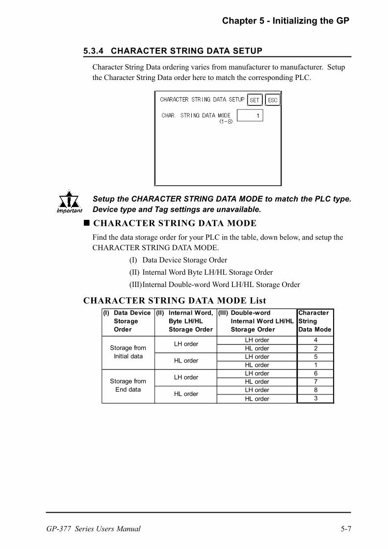
Character String Data ordering varies from manufacturer to manufacturer. Setupthe Character String Data order here to match the corresponding PLC.
Setup the CHARACTER STRING DATA MODE to match the PLC type.Device type and Tag settings are unavailable.
nnnnn CHARACTER STRING DATA MODE
Find the data storage order for your PLC in the table, down below, and setup theCHARACTER STRING DATA MODE.
(I) Data Device Storage Order
(II) Internal Word Byte LH/HL Storage Order
(III)Internal Double-word Word LH/HL Storage Order
CHARACTER STRING DATA MODE List(I) Data Device
StorageOrder
(II) Internal Word,Byte LH/HLStorage Order
(III) Double-wordInternal Word LH/HLStorage Order
CharacterStringData Mode
42516783
LH order
HL order
Storage fromInitial data
Storage fromEnd data
LH order
HL order
LH orderHL orderLH orderHL orderLH orderHL orderLH order
HL order
5.3.4 CHARACTER STRING DATA SETUP
Chapter 5 - Initializing the GP
GP-377 Series Users Manual5-8
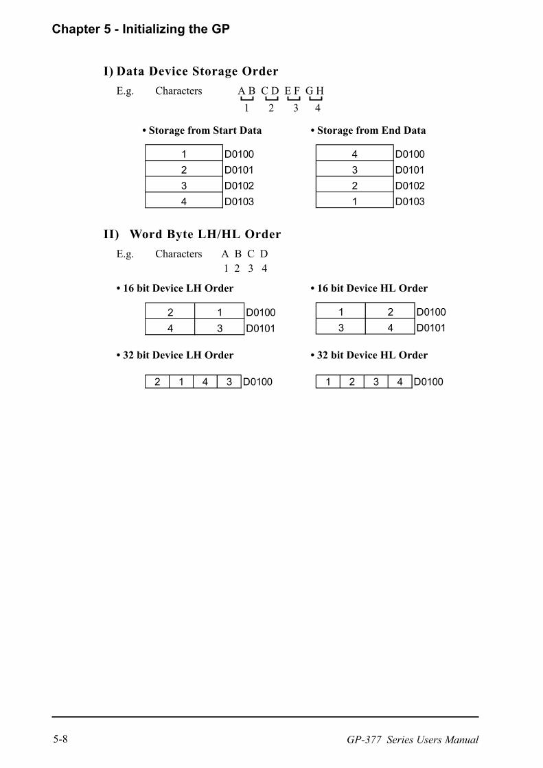
I) Data Device Storage Order
E.g. Characters A B C D E F G H
1 2 3 4
Storage from Start Data Storage from End Data
II) Word Byte LH/HL Order
E.g. Characters A B C D 1 2 3 4
16 bit Device LH Order 16 bit Device HL Order
32 bit Device LH Order 32 bit Device HL Order
1 D0100
2 D0101
3 D0102
4 D0103
4 D0100
3 D0101
2 D0102
1 D0103
2 1 D0100
4 3 D0101
1 2 D0100
3 4 D0101
2 1 4 3 D0100 1 2 3 4 D0100

Chapter 5 - Initializing the GP
GP-377 Series Users Manual 5-9
Relationship between K-tag Write Character Value and PLC Device
16 bit Devices
GP stores the character string from the start, as groups of 2, into1 PLC Device.
When there are nine characters, they are arranged as shown below.
1 2 3 4 5 6 7 8 9 Null
When the characters do not divide into 2 evenly, NULL is added at the end.
32 bit Devices
GP stores the character string from the start, as groups of 4, into1 PLC Device.
When there are nine characters, they are arranged as shown below.
1 2 3 4 5 6 7 8 9 Null
When the characters do not divide into 4 evenly, NULL is added at the end.
E.g. Characters "A B C D E F G H I J K L M N O P Q R S T"
1 2 3 4 5 6 7 8 9 10
32 bit Device LH Order 32 bit Device HL Order
III) Double-word Word LH/HL Order
E.g. Characters "A B C D E F G H I J"
1 2 3 4 5
16 bit Device LH Order 16 bit Device HL Order
2 D0100
1 D0101
4 D0102
3 D0103
5 D0104
1 D0100
2 D0101
3 D0102
4 D0103
5 D0104
2 1 D0100
4 3 D0101
6 5 D0102
8 7 D0103
10 9 D0104
1 2 D0100
3 4 D0101
5 6 D0102
7 8 D0103
9 10 D0104
Chapter 5 - Initializing the GP
GP-377 Series Users Manual5-10
This menu runs the settings related to PLC communication. Be sure to match thesettings listed below with the SIO setup on the PLC host.
GP-PRO/PBIII for Windows PLC Connection Manual (includedwith screen creation software)
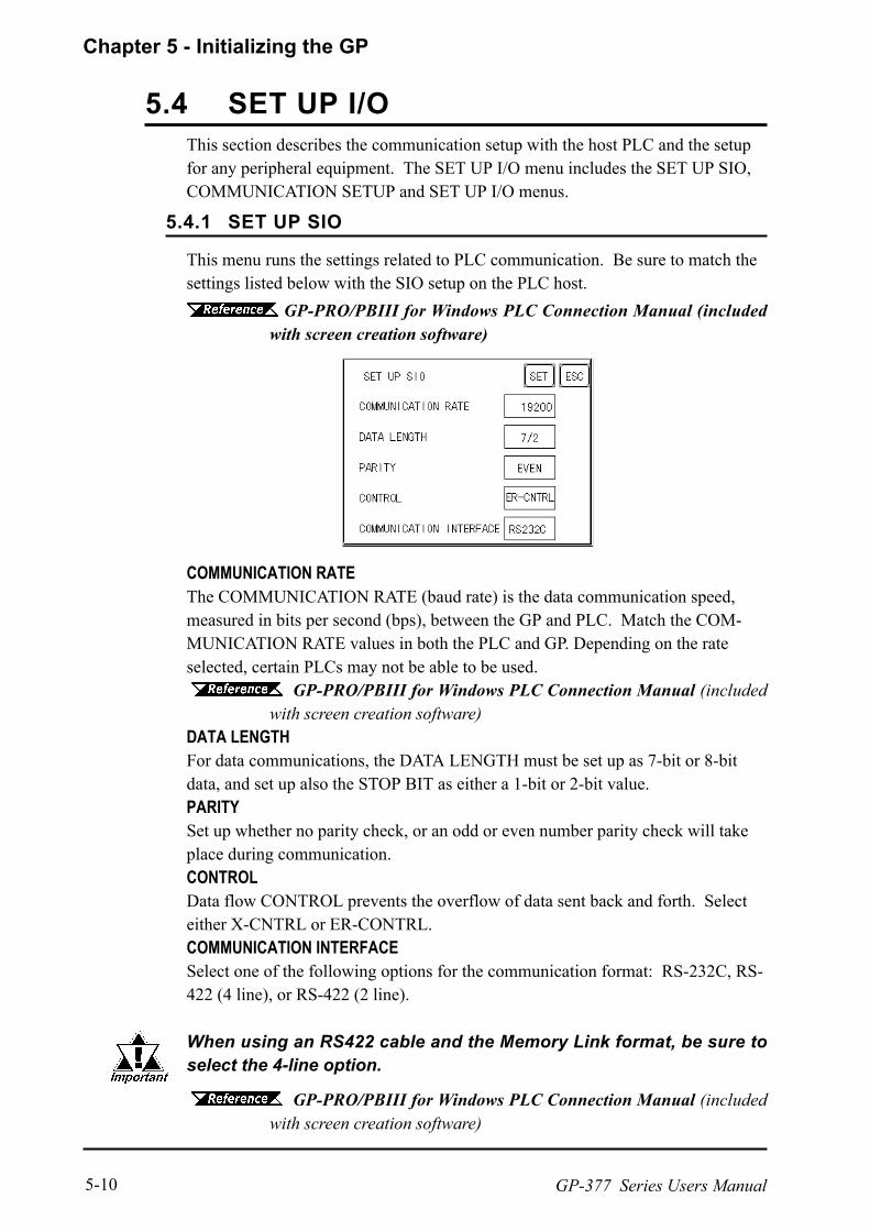
This section describes the communication setup with the host PLC and the setupfor any peripheral equipment. The SET UP I/O menu includes the SET UP SIO,COMMUNICATION SETUP and SET UP I/O menus.
COMMUNICATION RATEThe COMMUNICATION RATE (baud rate) is the data communication speed,measured in bits per second (bps), between the GP and PLC. Match the COM-MUNICATION RATE values in both the PLC and GP. Depending on the rateselected, certain PLCs may not be able to be used. GP-PRO/PBIII for Windows PLC Connection Manual (included
with screen creation software)DATA LENGTHFor data communications, the DATA LENGTH must be set up as 7-bit or 8-bitdata, and set up also the STOP BIT as either a 1-bit or 2-bit value.PARITYSet up whether no parity check, or an odd or even number parity check will takeplace during communication.CONTROLData flow CONTROL prevents the overflow of data sent back and forth. Selecteither X-CNTRL or ER-CONTRL.COMMUNICATION INTERFACESelect one of the following options for the communication format: RS-232C, RS-422 (4 line), or RS-422 (2 line).
When using an RS422 cable and the Memory Link format, be sure toselect the 4-line option.
GP-PRO/PBIII for Windows PLC Connection Manual (includedwith screen creation software)
5.4 SET UP I/O
5.4.1 SET UP SIO

GP-377 Series Users Manual 5-11
Chapter 5 - Installation and Wiring
RECEIVE TIMEOUTSets the value used for the data reception timeout (PLC - GP).
If the cable is not connected, data communication will Timeout in one second,regardless of this setting's value. The default is "10" seconds.
RETRY COUNTDesignates how many times the GP tries to send data to the PLC when a PLCcommunication error occurrs. An Error Message will appear on the GP after theGP tries to send data to the PLC the number of times set by this option. Thedefault is "2".
If you transfer screens when a PLC communication error has occurred and the erroris not yet cleared, and the RECEIVE TIMEOUT value is set to 30 seconds or more,an error message may appear on your personal computer.
5.4.2 COMMUNICATION SETUP

GP-377 Series Users Manual5-12
Chapter 5 - Installation and Wiring
Touch operation and Force Reset setup, and Display Device adjustments are madehere. There may be diffrences on these settings depending of the GP type.
GP-377L Setup Screen
GP-377S Setup Screen
TOUCH OPERATION MODEDesignates either One Point, Two Point or No Slide. When No Slide is selected,dragging one's finger across the touch screen will elicit no screen response, andonly individually selected points will register.
SYSTEM RESET MODEDesignates whether or not a SYSTEM RESET operation is performed.
uuuuuSteps to run SYSTEM RESET
While holding down the bottom right corner (1) of the screen, press the upperright corner (2). At the same time, press the bottom left corner (3) to enter theFORCE RESET Operation. To activate Reset, press the RESET button, to trans-fer to OFFLINE Mode, press OFFLINE.
!!!!!
5.4.3 SET UP TOUCH PANEL

GP-377 Series Users Manual 5-13
Chapter 5 - Installation and Wiring
FORCE RESET can occur during either RUN mode or OFFLINE mode.
The SYSTEM RESET mode cannot be entered while the GP is starting up.
Entering SYSTEM RESET is possible even when RUN operations (PLC <>GPcommunication) are not being performed.
CONTRAST SETTINGWhen CONTRAST SETTING is set to ON, you can adjust the contrast simplyby touching the GPs screen. If you wish to change to contrast adjustment mode,touch the screens top-right corner (see position 1 in the picture below), and thentouch also the top-left corner (see position 2.) while touching the top-right corner.When the screen B appears, touch the brightness level you wish to select and thescreens contrast will change.
BRIGHTNESS SETTINGWhen set to ON, BRIGHTNESS SETTING can be performed via touch input.Press the bottom left corner (2) of the screen while holding down the bottom rightcorner (1) to enter BRIGHTNESS SETTING mode. Touch the left-side of the barto brighten the display; touch the right-side of the bar to dim the display. This unithas four levels of adjustment.
The pictures shown here are for the GP-377S unit. Bright and Dark positionsare reversed on the GP-377L unit.
To end BRIGHTNESS SETTING mode, press anywhere outside the bottom of thescreen.
BRIGHTNESS SETTING mode cannot be entered while waiting for GP to startup.
BRIGHTNESS SETTING can be made even during RUN mode (PLC<-->GPcommunication).
The pictures shown here are for the GP-377S unit. Bright and Dark positionsare reversed on the GP-377L unit.
To end CONTRAST SETTING mode, press anywhere outside the bottom of thescreen.
CONTRAST SETTING mode cannot be entered while waiting for GP to start up. CONTRAST SETTING can be made even during RUN mode
(PLC<-->GP communication).
Bright Dark2 1
12A B
Bright Dark123123123

GP-377 Series Users Manual5-14
Chapter 5 - Installation and Wiring
*1 Bit +6 when using the Direct Access method, and bit +11 when using the Memory Linkmethod, will turn ON.
GP-PRO/PBIII for Windows PLC Connection Manual (includedwith screen creation software)
SET UP LCD (GP-377L only)To reverse the screen display colors, touch SET UP LCD on the SET UP I/Oscreen to change the setting from NORMAL to REVERSE, and then touchthe SET key. The display color will be reversed and the previous screen will re-appear.
USE TOUCH PANEL AFTER BACKLIGHT BURNOUTThis option designates whether touch-operation is disabled or not when the back-light burns out.
If this selection is set to [OFF], touch-operation will be disabled when the back-light burns out, which prevents the GP from sending input signals to the PLC.
When the backlight burns out, the Status LED's orange light turns ON, and theSystem Data Area's "Status" bit 10*1 will turn ON.
If the [SYSTEM RESET] option is set to [ON], only "System Reset" can still beperformed by touch-operation in case of backlight burnout.
If the backlight burns out when the GP is OFFLINE, touch-panel operation is en-abled, regardless of these settings.
Normally, the unit detects backlight burnout by monitoring the currentflow, however, the unit may fail to detect this condition depending onthe problem type the backlight has.

GP-377 Series Users Manual 5-15
Chapter 5 - Installation and Wiring
The GPs screen may flicker, or there may be shadows appearing on extendeddisplay lines on the LCD surface. In the case where the GPs ambient temperaturebecomes high, and its current brightness level is set to low, this effect may bemore pronounced. This phenomenon is however, a common attribute of LCDs andis not a defect. To solve this, use this setting for adjusting the GPs brightness.
When Using GP-377L
When Using GP-377S
Current ValueTo solve the above problem, touch + or - to adjust the brightness. You cancheck the actual brightness in the preview field at the bottom of the screen. Fromthe default value of 0 there are 18 + levels and 2 - levels available.
Set Default ValueIf you touch Default, the setting returns to 0.
5.4.4 DISPLAY SETUP
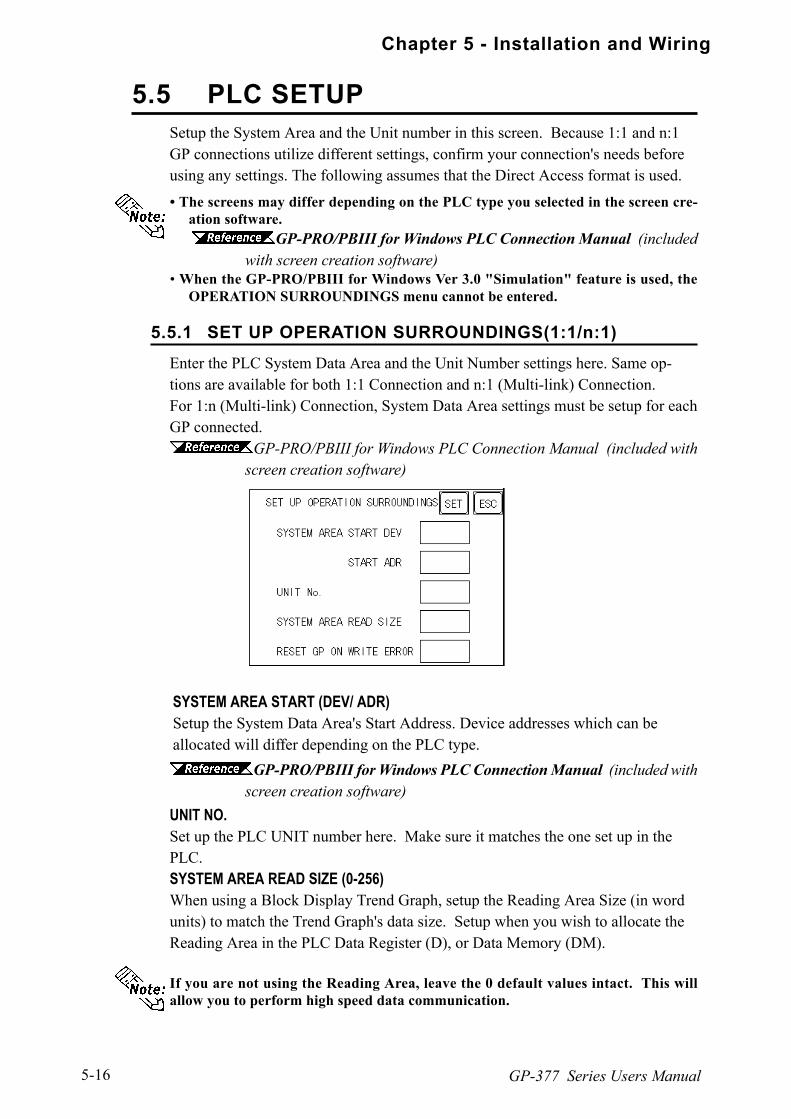
GP-377 Series Users Manual5-16
Chapter 5 - Installation and Wiring
Enter the PLC System Data Area and the Unit Number settings here. Same op-tions are available for both 1:1 Connection and n:1 (Multi-link) Connection.For 1:n (Multi-link) Connection, System Data Area settings must be setup for eachGP connected.
GP-PRO/PBIII for Windows PLC Connection Manual (included withscreen creation software)
SYSTEM AREA START (DEV/ ADR)Setup the System Data Area's Start Address. Device addresses which can beallocated will differ depending on the PLC type.
Setup the System Area and the Unit number in this screen. Because 1:1 and n:1GP connections utilize different settings, confirm your connection's needs beforeusing any settings. The following assumes that the Direct Access format is used.
The screens may differ depending on the PLC type you selected in the screen cre-ation software.
GP-PRO/PBIII for Windows PLC Connection Manual (includedwith screen creation software)
When the GP-PRO/PBIII for Windows Ver 3.0 "Simulation" feature is used, theOPERATION SURROUNDINGS menu cannot be entered.
UNIT NO.Set up the PLC UNIT number here. Make sure it matches the one set up in thePLC.SYSTEM AREA READ SIZE (0-256)When using a Block Display Trend Graph, setup the Reading Area Size (in wordunits) to match the Trend Graph's data size. Setup when you wish to allocate theReading Area in the PLC Data Register (D), or Data Memory (DM).
If you are not using the Reading Area, leave the 0 default values intact. This willallow you to perform high speed data communication.
GP-PRO/PBIII for Windows PLC Connection Manual (included withscreen creation software)
5.5 PLC SETUP
5.5.1 SET UP OPERATION SURROUNDINGS(1:1/n:1)

GP-377 Series Users Manual 5-17
Chapter 5 - Installation and Wiring
RESET GP ON WRITE ERRORDesignates the mode which enables you to cancel the error from the error displaywhen the Write error occurs.
The STATION SETUP, necessary for the n:1 (Multi-link) setup, checks whethercorrect communications run with the connected GP System configuration.
NETWORK INFORMATION (DEV/ADR)In the n:1 (multi-link) connection, the Network Information uses 2 words in itscorrespondences. These two (2) words consist of a Connection List and a Valida-tion List (described later in this section). These areas are allocated in the PLC'sData Register (D) or Data Memory (DM). Adresses which can be allocated willdiffer depending on the PLC type.
GP-PRO/PBIII for Windows PLC Connection Manual (included withscreen creation software)
PLC Data Register
In the NETWORK INFORMATION ADR, setup the same address to allthe GP's connected to the same link unit. Furthermore, when there are2 ports in the connected link unit, do not make them the same address.
uuuuuConnection ListThe word address for the Connection List sets up the number of GP's connected tothe PLC, which must be registered beforehand on the PLC side. When these GP'sare connected to the PLC, the corresponding PLC bit numbers for the particularGP Stations (see below) turn ON.
When the GP is connected to the PLC, and the option of GP only correspondenceends and OFFLINE mode is entered, the GP Station Number then turns the corre-sponding PLC bit OFF.
Bit 0Bit 15
5.5.2 STATION SETUP(n:1)

GP-377 Series Users Manual5-18
Chapter 5 - Installation and Wiring
For example, when these 4 GP unitsbit 0, bit 2, bit 3, bit 5are connected,002D (h) is written here.
Be certain to setup this data before running.
Turn all bits not related to the GP OFF.
uuuuu Validation ListThis area responds to the correspondence from each connected GP. In the Valida-tion List, when the same bit numbers as the Connection List turn ON, the corre-spondence is accepted. The Station Numbers of the communicating GPs turn theircorresponding PLC bit number ON.
If the correspondence between the GP and PLC is correct, the same value as in theConnection List is written to the Validation List.For example, the value 002D (h) in the Connection List, setup as the 0 bit, 2 bit, 3bit, and 5 bit, writes to the Validation List.
When the Connection List and Validation List do not match, a COM-MUNICATION ERROR occurs. Check the setup again.
When changing the connection, first turn all the bits OFF.
STATION NO. (0-15)This is the setup for the GP Station Number mentioned above. The setup range isfrom 0 to 15, and the only other restriction is the GP STATION NO. must beunique in the system. If STATION NO.'s are repeated, a COMMUNICATIONERROR occurs.
The STATION NO. is the number allocated to the particular GP unit. This number isnot related to the Link Unit Machine number.
00000000 0000
00000000 0000
00000000 10110100
Bit 0
1111
1111
Connection List 002D (h)
Connection List
Validation List
002D (h)
002D (h)
Bit 15
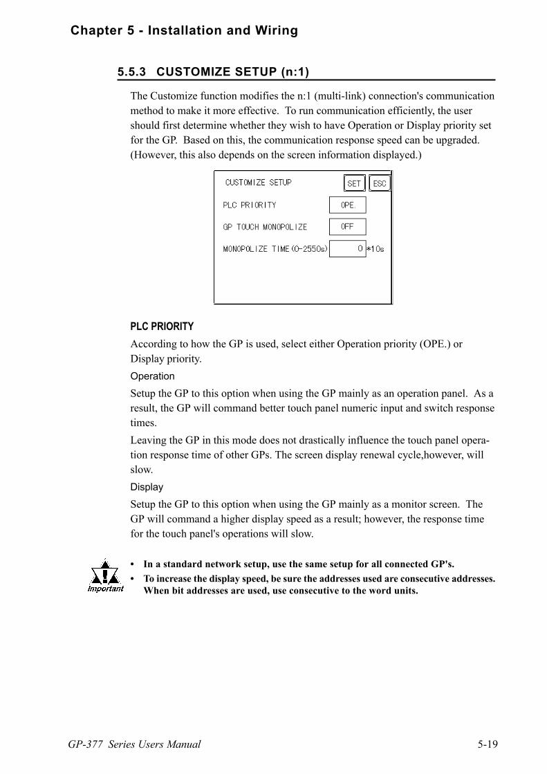
GP-377 Series Users Manual 5-19
Chapter 5 - Installation and Wiring
PLC PRIORITYAccording to how the GP is used, select either Operation priority (OPE.) orDisplay priority.
Operation
Setup the GP to this option when using the GP mainly as an operation panel. As aresult, the GP will command better touch panel numeric input and switch responsetimes.
Leaving the GP in this mode does not drastically influence the touch panel opera-tion response time of other GPs. The screen display renewal cycle,however, willslow.
Display
Setup the GP to this option when using the GP mainly as a monitor screen. TheGP will command a higher display speed as a result; however, the response timefor the touch panel's operations will slow.
In a standard network setup, use the same setup for all connected GP's.
To increase the display speed, be sure the addresses used are consecutive addresses.When bit addresses are used, use consecutive to the word units.
The Customize function modifies the n:1 (multi-link) connection's communicationmethod to make it more effective. To run communication efficiently, the usershould first determine whether they wish to have Operation or Display priority setfor the GP. Based on this, the communication response speed can be upgraded.(However, this also depends on the screen information displayed.)
5.5.3 CUSTOMIZE SETUP (n:1)

GP-377 Series Users Manual5-20
Chapter 5 - Installation and Wiring
GP TOUCH MONOPOLIZEThe monopolizing of touch panel use can be set ON or OFF. When you want touse the PLC exclusively with a Momentary operation setup on the touch panel,turn GP TOUCH MONOPOLIZE ON.
When this setup is ON, the touch panel uses the PLC exclusively whenever themomentary operation setup on the panel is pressed. In this way, you can use theinching operation with a momentary switch. When you stop pressing the panel,exclusive use ends.
GP-PRO/PBIII for Windows PLC Connection Manual (includedwith screen creation software)
MONOPOLIZE TIME (0-2550S)This field controls the length of time for the monopolize process when no othertouch panel operations are performed. The Monopolize process begins when theSystem Data Area's 7th bit of word address LS14 turns ON, and ends either whenthe bit turns OFF, or when the time set here elapses.
Pressing the touch panel in the middle of the monopolize process interrupts theMONOPOLIZE TIME function, and ends exclusive use.
When MONOPOLIZE TIME is set to 0, the monopolize function does not endautomatically.
For further imformation about the contents of System Data Area LS6 (status) andLS14 (control) GP-PRO/PBIII for Windows PLC ConnectionManual (included with screen creation software)
Speed Difference between Display Priority and Operation Priority
When using the Mitsubishi Electric Corp. A3A PLC, with consecutive addresses(80 words not included in the System Area), the difference in reading speed is asshown in the following graphs.

GP-377 Series Users Manual 5-21
Chapter 5 - Installation and Wiring
To initialize the GP internal memory, enter the common password 1101, or thepassword entered in the SYSTEM SET UP screen.
Chapter 4.3, "INITIALIZE-Standard Operation"
The time required for Initialization is between 10 and 20 seconds.
This command erases all the GP screen data and initializes the GP's SRAM.
You cannot cancel the Initialization procedure after pressing the Startkey.
AIl backed up data in SRAM is lost. Initialization does not erase the SYSTEM SET UP, the SIO protocol, or
the internal clock settings.
Sets the GP's internal clock.
SET UP TIMEEnter date and time corrections to the date and time displayed in the PRESENTTIME.
The GP's internal clock has a slight error. At normal operating temperatures andconditions, with the GP operating from its lithium battery, the degree of error is 65seconds per month. Variations in operating conditions and battery life can cause thiserror to vary from +65 to -350 seconds per month. For systems where this degree oferror will be a problem, the user should be sure to monitor this error and make ad-justments when required.
5.6 INITIALIZE INTERNAL MEMORY
5.7 SET UP TIME

GP-377 Series Users Manual5-22
Chapter 5 - Installation and Wiring
This screen is used to enter the number for the initial screen displayed after pow-ering up, the character size when in RUN mode, and other general screen items.
INITIAL SCREEN NO.Set up the screen file number that will display first upon powering up. If the BINoption for DATA TYPE OF SCREEN NO in SYSTEM SET UP had been se-lected, enter a number from 1 to 8999. Or, if BCD was the option set up, theninput a number from 1 to 1999.
ALARM MESSAGESet up the character size of the ALARM MESSAGE when the Alarm Bulletin isactivated.
ONLINE ERROR DISPLAYSet up whether or not error messages display during RUN mode.
<When using single-byte characters>
<When using double-byte characters>
V size=4; H size=464×32 pixels
41V size=1; H size=116×8 pixels
2V size=2; H size=232×16 pixels
V size=1; H size=116×16 pixels
V size=2; H size=232×32 pixels
V size=4; H size=464×64 pixels
5.8 SET UP SCREEN
GP-377 Series Users Manual 5-23
Chapter 5 - Installation and Wiring
5.9 FONT SETTING
FONT SETTINGSelect the character font that displays during RUN mode. Available selections are[EUROPE], [JAPAN], [KOREA], [CHINESE] and [TAIWANESE].
KANJI FONT QUALITYuWhen [FONT SETTING] is set to [JAPAN]Single-byte characters will remain 8x16-dot characters when they are enlarged.Double-byte characters are displayed as:
[Standard] Here, characters are displayed as 16x16-dots. When enlarged, thisfont will remain a 16x16-dot character. (Compatible with GP-*30series units.)
[HIGH] When enlarged to double-size, Level 1 JIS Kanji Code charactersare displayed as 32x32-dot characters. Level 2 JIS Kanji Codecharacters remain 16x16-dot characters. (Compatible with GP-*50series and GP-70 series units.)
[1,2] When enlarged to Double-byte size, both Level 1 and Level 2 JISKanji Code characters are displayed as 32x32-dot characters.
uWhen [FONT SETTING] is set to any other type (i.e. CHINESE, I-ASCII,KOREA or TAIWAN)
[Standard] When enlarged, single-byte characters will remain 8x16-dot characters, and double-byte characters will remain 16x16-dot characters.(Compatible with GP-*30 series units.)
[HIGH] Single-byte characters (ASCII codes 21h to 7Dh) except < > and< ~ > will display as high quality characters. 16x16-dot characters will display using Japanese font *1, 16x16- dot characters. 32x32-dot characters can only be displayed as Japanese font, 32x32-dot characters.When enlarged, double-byte characters remain 16x16-dot characters.
[1,2] Single-byte characters (ASCII codes 21h to 7Dh) except < > and < ~ > will display as high quality characters using Japanese fonts. 16x16-dot characters will display as Japanese font 16x16-dot characters. 32x32-dot characters will display as Japanese font 32x32-dot characters.
When enlarged to double-size (32x32-dot) or larger, double-byte characters(KOREA, TAIWAN, CHINESE) will display as 32x32-dot characters.
*1 Japanese font here means the 2 types (16x16-dot font and 32x32-dot font) of fontsused in the JAPAN setting.

GP-377 Series Users Manual 5-24
Memo
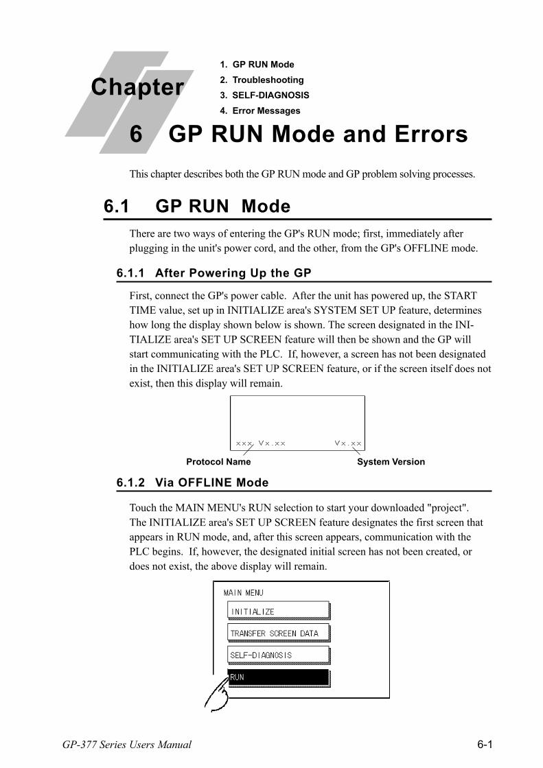
GP-377 Series Users Manual 6-1
First, connect the GP's power cable. After the unit has powered up, the STARTTIME value, set up in INITIALIZE area's SYSTEM SET UP feature, determineshow long the display shown below is shown. The screen designated in the INI-TIALIZE area's SET UP SCREEN feature will then be shown and the GP willstart communicating with the PLC. If, however, a screen has not been designatedin the INITIALIZE area's SET UP SCREEN feature, or if the screen itself does notexist, then this display will remain.
There are two ways of entering the GP's RUN mode; first, immediately afterplugging in the unit's power cord, and the other, from the GP's OFFLINE mode.
Touch the MAIN MENU's RUN selection to start your downloaded "project".The INITIALIZE area's SET UP SCREEN feature designates the first screen thatappears in RUN mode, and, after this screen appears, communication with thePLC begins. If, however, the designated initial screen has not been created, ordoes not exist, the above display will remain.
This chapter describes both the GP RUN mode and GP problem solving processes.
6.1 GP RUN Mode
Chapter
6 GP RUN Mode and Errors
1. GP RUN Mode
2. Troubleshooting
3. SELF-DIAGNOSIS
4. Error Messages
6.1.1 After Powering Up the GP
System Version Protocol Name
6.1.2 Via OFFLINE Mode
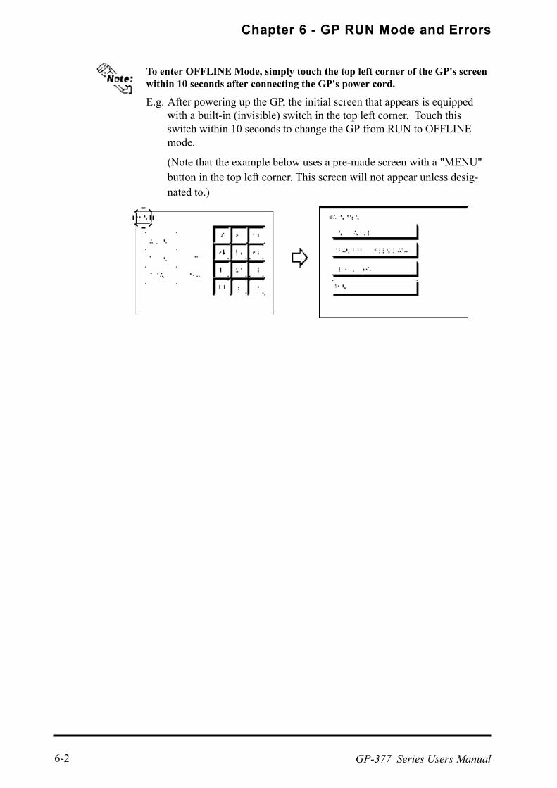
Chapter 6 - GP RUN Mode and Errors
GP-377 Series Users Manual6-2
To enter OFFLINE Mode, simply touch the top left corner of the GP's screenwithin 10 seconds after connecting the GP's power cord.
E.g. After powering up the GP, the initial screen that appears is equippedwith a built-in (invisible) switch in the top left corner. Touch thisswitch within 10 seconds to change the GP from RUN to OFFLINEmode.
(Note that the example below uses a pre-made screen with a "MENU"button in the top left corner. This screen will not appear unless desig-nated to.)
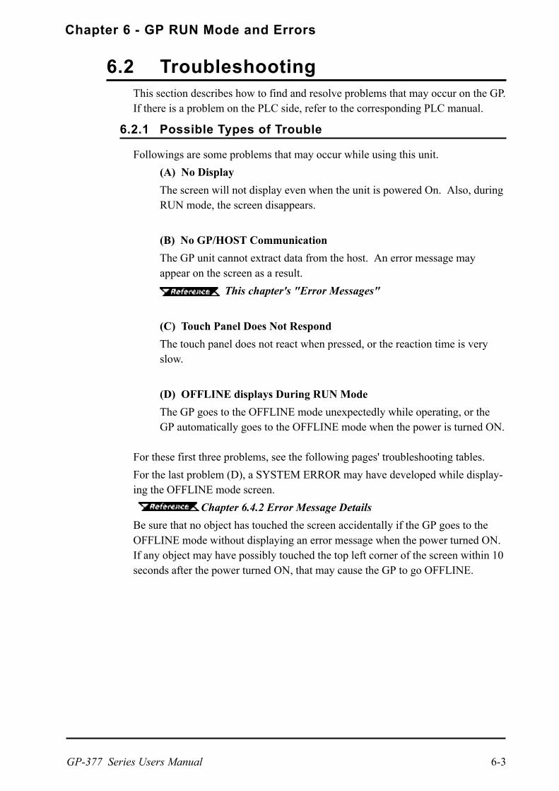
Chapter 6 - GP RUN Mode and Errors
GP-377 Series Users Manual 6-3
Followings are some problems that may occur while using this unit.
(A) No Display
The screen will not display even when the unit is powered On. Also, duringRUN mode, the screen disappears.
(B) No GP/HOST Communication
The GP unit cannot extract data from the host. An error message mayappear on the screen as a result.
This chapter's "Error Messages"
(C) Touch Panel Does Not Respond
The touch panel does not react when pressed, or the reaction time is veryslow.
(D) OFFLINE displays During RUN Mode
The GP goes to the OFFLINE mode unexpectedly while operating, or theGP automatically goes to the OFFLINE mode when the power is turned ON.
For these first three problems, see the following pages' troubleshooting tables.
For the last problem (D), a SYSTEM ERROR may have developed while display-ing the OFFLINE mode screen.
Chapter 6.4.2 Error Message Details
Be sure that no object has touched the screen accidentally if the GP goes to theOFFLINE mode without displaying an error message when the power turned ON.If any object may have possibly touched the top left corner of the screen within 10seconds after the power turned ON, that may cause the GP to go OFFLINE.
This section describes how to find and resolve problems that may occur on the GP.If there is a problem on the PLC side, refer to the corresponding PLC manual.
6.2 Troubleshooting
6.2.1 Possible Types of Trouble

Chapter 6 - GP RUN Mode and Errors
GP-377 Series Users Manual6-4
Follow the flowchart below when the screen does not display when powering up,or the screen turns OFF by itself during RUN mode, to find an appropriate solu-tion.
Is the GP's voltagecorrect?
Has data beentransferred from the
Screen editor?
YES
YES
YES
YES
NO
Disconnect the SIO and AUX cable.
Does turning ON thepower one more timecause a display?
NOTransfer screen data from thescreen editing software.
Chapter 4.5,"Transfer Screen Data"
Use the correct power voltage.Chapter 2,
"Specifications"
Fix the power code connection. Chapter 3, "Installa-
tion and Wiring"
Turn OFF the power and reconnectthe SIO cable, or the AUX cable.
Does the Status LEDlight turn On?
NO
No Screen Display
Unplug the GP's power cord.
Is the power codeconnected properly to
this unit?
NO
YES
6.2.2 Troubleshooting Flow Chart
NO

Chapter 6 - GP RUN Mode and Errors
GP-377 Series Users Manual 6-5
YES
Possible problems with thePLC. Check if the PLC isworking properly.
NO
YES
Set up the correct Screen filenumber.
C h a p t e r 5 ,"Initializing the GP".
Does turning the powerON one more time startthe display?
Go to OFFLINE mode.*1(Press the upper left cor-ner of the screen)
NO
See if INITIALIZE/ SETUP SCREEN is OK.
Does the OFFLINEmenu display?
NO
Is the Status LED'sorange light ON?
YES
Connect the cable properly.Chapter 3, "Installa-
tion and Wiring" & PLC Connec-tion Manual (included with thescreen creation software)
The back light has burnedout. Contact your nearestGP distributor for thebacklight replacement.
NO
YES
*1 To make the OFFLINE screen appear, turn the power OFF, then ON, and press theupper left corner of the screen within 10 seconds.
NO
The SIO cable,or the AUXcable was notconnectedproperly.
YES
Is the SIO cable,AUX cable connectedproperly to this unit?
NO

Chapter 6 - GP RUN Mode and Errors
GP-377 Series Users Manual6-6
Run SELF-DIAGNO-SIS INTERNAL
FEPROM CHECK*1.Is it OK?
*1 When you run the SELF-DIAGNOSIS area's FEEPROM CHECK , all screen data iserased. Therefore, be sure to make a backup of all GP screens prior to performingthis check.
Erase the data that has been written.When using Direct Access, theaddress is +9; when using MemoryLink, the address is 12. For moreon the SYSTEM DATA AREA
PLC ConnectionManual (included with the screencreation software)
YES
NO
There is a problem with the GPunit. Please contact your localGP distributor.
NO
YES
Has Display Off databeen written to theSYSTEM DATA
AREA?
NO
YES
YES
Has Backlight Offdata been written tothe SYSTEM DATA
AREA?
There may be an error occurredwithin Internal FEPROM*2 Datawhile being transferred.
Initialize the FEPROM, transfer thedata, and try using again.
Erase the data that has been written.When using Direct Access, theaddress is +14; when using MemoryLink, the address is 11. For more onthe SYSTEM DATA AREA
PLC ConnectionManual (included with the screencreation software)
*2 Also known as "FEEPROM" (Flash Electronic Erasable Programmable Read OnlyMemory).

Chapter 6 - GP RUN Mode and Errors
GP-377 Series Users Manual 6-7
YES
NO
Disconnect all the cables except thepower cable and turn the unit ON.
Setup the protocol that correspondswith the connected PLC.
PLC ConnectionManual (included with the screencreation software)
For RS-422, use the solutions pro-vided in the dotted rectangle, above.
Install the Termination Resistor in thecorrect position with the correct values.Resistor position and values changewith each PLC type. When using theDirect Access format,
PLC ConnectionManual (included with the screencreation software)
Does not communicate
Is the Termination Resis-tor correctly installed?
When the GP will not communicate with the host PLC, follow the flowchartbelow to find both the cause of the problem and a suitable response.
Or, if an error message displays on the screen, check the error code (refer to theError Messages section in this chapter) to find the appropriate solution.
6.2.3 No GP/Host Communication
Unplug the GP's power cord
Has the correct PLCprotocol (Table file)
been selected?
Is the SIO cable attachedproperly to this unit?
NO
YES
NO
YES
Attach the SIO cable unit properly,making sure all connections are secure.
PLC ConnectionManual (included with the screencreation software)

Chapter 6 - GP RUN Mode and Errors
GP-377 Series Users Manual6-8
NO
YES
YES
NO
YES
NO
Check the tag data, andcorrect the setup values.
TagReference Manual(included with thescreen creationsoftware)
Possible problems with thePLC. Check if the PLC isworking properly.
There is a problemwith the GP unit.Please contact yourlocal GP distributor.
Are the correspondingSIO INITIALIZE settings
OK?
Is the SELF-DIAGNOSIS/SIO CHECK OK?
Enter correct settings andvalues.
Chapter 5"Initializing the GP". Are all Tags set
up correctly?

Chapter 6 - GP RUN Mode and Errors
GP-377 Series Users Manual 6-9
When the touch panel does not respond, or its response time is very slow after it ispressed, please use the flowchart below to find the origin of the problem, and theappropriate solution.
Disconnect all the cables (includ-ing SIO cable and AUX cable), ex-cept the Power cable.
YES
NO
Are the settings fortouch input tags, or for
Parts correct?
Run SELF-DIAGNO-SIS/ TOUCH PANELCHECK to see the GP
is OK
YESSet the addresseswithin the allow-able range,or re-define the toucharea.
YES
Is INITIALIZE's SETUP TOUCH PANEL
correct?
NO
NO
In the INITIALIZE/ SET UPTOUCH PANEL option, enter val-ues applicable to the Touch Opera-tion Mode.
Chapter 5 "Initializ-ing the GP"
Connect each piece of peripheralequipment (i.e. Transfer Cable,Barcode Reader, etc.) to the GPand then turn it ON to check if theTouch Panel operates correctly.
YES
Peripheral equip-ment is malfunc-tioning.
The error may be causedby peripheral equipment.
There is a problem with theGP unit. Please contact yourlocal GP distributor.
NO
6.2.4 Touch Panel Does Not Respond
Touch panel not responding

Chapter 6 - GP RUN Mode and Errors
GP-377 Series Users Manual6-10
6.3 SELF-DIAGNOSIS
The GP unit is equipped to check its own System and Interface for any problems.Use it to help diagnose any problems.
6.3.1 GP SELF-DIAGNOSIS Item List
DISPLAY PATTERNChecks all the figures and tiling patterns.
TOUCH PANELChecks each GP touch panel square.
FEPROM CHECKSUMChecks the System and Protocol of the GP Internal Memory (FEPROM*1).
FRAME BUFFERChecks the internal display memory (Frame Buffer).
TOOL CONNECTOR *2
Checks the Tool Connector control lines and send/receive lines.
INPUT PORTChecks the Input Port (for Digital's maintenance use only).
SIO CHECK *2
Checks the RS-232C and RS-422 send/receive lines.
*1 Also known as "FEEPROM" (Flash Electronic Erasable Programmable Read OnlyMemory).
*2 This item requires special tools. Please prepare the required tool for the test.

Chapter 6 - GP RUN Mode and Errors
GP-377 Series Users Manual 6-11
DISPLAY PATTERNUsed when the buzzer will not sound and when the device contents will notdisplay correctly to check the drawing function. It does this by running checks onthe various screen pattern displays (8 screens), the ON/OFF Display, andKANJIROM CHECKSUM. When the ON/OFF Display is checked, the BuzzerON/OFF check is run simultaneously. If KANJIROM CHECKSUM is normal,OK displays; if there is a problem, NG displays.
TOUCH PANELTouch Panel check. Checks if each touch cell highlights when pressed.
INPUT PORTUsed only for Digital's maintenance.
INTERNAL FEPROM CHECKSUM (System & Protocol)The Internal FEPROM*1 System and Protocol check searches for any problemsthat may arise during operations. When running the check, the screen will changeas follows.
When the FEPROM is normal, OK displays; if there is a problem, the screen stopsin the middle of operation. This check does not erase the System or Protocol.
FRAME BUFFERThe Frame Buffer (display memory) Check looks for any display problems thatmay develop. When everything is normal, OK displays; when there is a problem,an error message displays.
This section explains the contents of SELF-DIAGNOSIS. For information onhow to operate the Screen, Chapter 4, "OFFLINE Mode"; forinformation about how to set up the Special Tools, Chapter 3,"Installation and Wiring".
6.3.2 SELF-DIAGNOSIS - Details
*1 Also known as "FEEPROM" (Flash Electronic Erasable Programmable Read OnlyMemory).
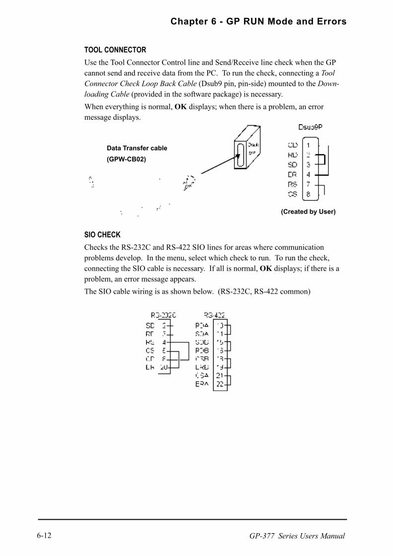
Chapter 6 - GP RUN Mode and Errors
GP-377 Series Users Manual6-12
TOOL CONNECTORUse the Tool Connector Control line and Send/Receive line check when the GPcannot send and receive data from the PC. To run the check, connecting a ToolConnector Check Loop Back Cable (Dsub9 pin, pin-side) mounted to the Down-loading Cable (provided in the software package) is necessary.
When everything is normal, OK displays; when there is a problem, an errormessage displays.
(Created by User)
Data Transfer cable
(GPW-CB02)
SIO CHECKChecks the RS-232C and RS-422 SIO lines for areas where communicationproblems develop. In the menu, select which check to run. To run the check,connecting the SIO cable is necessary. If all is normal, OK displays; if there is aproblem, an error message appears.
The SIO cable wiring is as shown below. (RS-232C, RS-422 common)

Chapter 6 - GP RUN Mode and Errors
GP-377 Series Users Manual 6-13
This section explains the messages that appear when an error has occurred in theGP unit during RUN mode. The problem causing the error message and itsrelated countermeasure are explained in the table below.After a problem has been solved, unplug the GP's power cord and then reattach it.(Only the most recent error message will appear on the GP screen)
Error Message Problem CountermeasureSYSTEM ERROR(03 : **)
During screen data transfer, anunrecoverable error occurred. 6.4.2 Error Message Details
SYSTEM ERROR(*** : *** : ***)
During screen data transfer, anunrecoverable error occurred. 6.4.2 Error Message Details
ILLEGAL ADDRESS INSCREEN DATA
Settings are used that overlap addresses. Set the addresses correctlyafter checking the screen data.
UNSUPPORTED TAG INSCREEN DATA
The GP currently in use does not supportthe desired Tag.
Set the Tag correctly afterchecking the screen data.
PLC NOT CONNECTED(02 : FF) and (02 : F7)
The communication cable is not connectedcorrectly.
Re-connect thecommunication cable correctly.
PLC's power is not turned ON. Turn ON the PLC's power.
GP unit INITIALIZE settings (Setup I/O, PLCSetting) are incorrect.
Check the INITIALIZE settingsand make any necessarycorrections.
The host and GP Powering up sequencewas incorrect.
Turn ON the PLC's power andwait for 2-3 seconds, then turnON the GP's power.
The communication cable is not connectedproperly.
Check the communicationcable and connect it correctly.
The communication cable wasdisconnected while the GP was ON.
Turn the GP OFF and then ONagain.
The GP is powered OFF, then ON duringcommunication with PLC.
Turn the GP OFF and then ONagain.
Noise occurred in the communication cable. Check the communicationcable and connect it correctly.
This GP's station number is same asanother GP.
Check all GP station numbers,and set them so they are allunique.
PLC is powered OFF, then ON duringcommunication with GP.
Turn the GP OFF and then ONagain.
NETWORK ADDRESSERROR (02 : F8)
The SIO address used for this GP isdifferent from other GP's. (Only for the Multi-Link connection)
Check all GP's SIO addresssettings, and correct any thatare incorrect.
PLC COM. ERROR(02 : **)
Specific PLC related error, or an error hasoccurred with the PLC. 6.4.2 Error Message Details
PLC NOT RESPONDING(02 : FE)
RECEIVE DATA ERROR(02 : FD)
GP STATION NO.DUPLICATION ERROR(02 : F9)
6.4 Error Messages
6.4.1 Error Message List

Chapter 6 - GP RUN Mode and Errors
GP-377 Series Users Manual6-14
SCREEN MEMORYDATA IS CORRUPT(nnnn:mmmm)
ScreenData is corrupted:*nnnn indicates the Screen Number thathas an error.*mmmm indicates the number of screensthat have errors.(Decimal)
Check the screens that haveerrors, correct all errors, andthen transfer the screen dataagain.
CLOCK SETUP
ERROR *1
The backup battery for the internal clock isrunning low. 6.4.2 Error Message Details
SCREEN TRANSFERERROR
An error occurred in the data transmissionfrom the screen editor to the GPpanel.
Re-transfer the screen data.
SCREEN TAG LIMITEXCEEDED
Tags are setup beyond the tag limit (max. of385.) 6.4.2 Error Message Details
OBJ. PLC HAS NOTBEEN SETUP (**)
The host PLC set up in the Editor programdoes not match the PLC in use. 6.4.2 Error Message Details

Chapter 6 - GP RUN Mode and Errors
GP-377 Series Users Manual 6-15
6.4.2 Error Message Details
u u u u u SYSTEM ERROR ( 03 : x x )
An unrecoverable error occurred during screen data transfer.
03 : x x
Possible Solutions
Check if the GP's Power Cord and the Input signal line have been wired sepa-rately from each other.
Check that the FG line has been grounded correctly, according to your country'sstandards.
Re-send the screen data from the PC to the GP.
If other types of communication errors, such as [RECIEVE DATA ERROR],[PLC COM. ERROR], have also occurred, try to correct those problems also.
6.4.1 Error Message List
If the above mentioned methods do not solve the problem, please contact yourlocal GP distributor.
n SYSTEM ERRORS
Indicates a fault in the basic operations of the GP.Following the error message, an error code, as shown below, will appear. Reportthe error number and details on how the error developed to your local GP distribu-tor.
u u u u u SYSTEM ERROR ( x x x : x x x : x x x )
An unrecoverable error occurred during screen data transfer.
x x x : x x x : x x x
Error No.
Constant Value
Error No. 3
Error No. 2
Error No. 1

Chapter 6 - GP RUN Mode and Errors
GP-377 Series Users Manual6-16
nnnnn When OFFLINE mode displays during RUN mode
When the GP changes to OFFLINE mode without the user first pressing thescreen, there is a possibility that the screen data has been damaged. In this case,after the SYSTEM ERROR displays, the screen automatically reverts to OFFLINEmode after about 10 seconds. Run the INITIALIZE MEMORY command andtransfer the GP screen data again from your PC.
In most cases, system errors are related to the problems mentioned below.
Environment Related Problems
If an error occurs which has no apparent connection to the GPs current operation,the error may be due to the condition of GPs operating environment. This caninclude noise or electrostatic interference in the power code or the communicationline. In this case you need to check if the power code and the communication linewiring and FG grounding are correct.
Screen Data or Project Data Related Problems
If an error seems to be caused by a particular GP operation, the error may berelated to the screen or project data transferred to the GP. In this case, try sendingscreen data via the FORCE SYSTEM SETUP feature, which will transfer both thescreen data and the project data to the GP.
For details about the FORCE SYSTEM SETUP feature, refer to GP-PRO/PBIII for Windows Ver.3.0 Operation Manual Chapter 11-2-1, Transfer Set-tings.
GP Unit Related Problems
If disconnecting and then re-connecting the power code corrects an error, theproblem may not be related to the GP unit itself. However, to identify if the GPunit has any problems, run the OFFLINE modes SELF-DIAGNOSIS program.
Peripheral Equipment Related Problems
(When the GP is equipped with a printer I/F)
If an error occurs only during printout, there may be a problem with the printer.Check the printer cable wiring and the FG line as well as the printer itself.
When a communication error occurs continuously
(When using the Direct Access method)
If a communication error occurs continuously, the GP may define the error as asystem error. In this case you need to solve the problem causing the originalcommunication error.

Chapter 6 - GP RUN Mode and Errors
GP-377 Series Users Manual 6-17
Tag Name/ Part ID No. Word Address Tag FormatN1 99 BCD32
Error 1 Error 2 Meaning
191
192
193
194
195
196
197
198
199
0C9 19BAll or part of a T-tag
*1, S-tag or K-tag address
range overlap the address range set in an A-tag (Log alarm.)
0C1
0C2
0C3
All or part of the T-tag *1
or S-tag address
range overlap the addresses of System DataArea.
All or part of the System Data Area address,A-tag, or S-tag address range overlap the
addresses setup in a T-tag. *1
All or part of a T-tag*1
, S-tag or K-tag address
range overlap the address range set in an A-tag (Alarm Message.)
n ILLEGAL ADDRESS IN SCREEN DATA
Caused by an overlap of addresses.After the error message, error codes, as listed below will appear. If the errorcannot be fixed, please report the error code and details on how the error devel-oped to your local GP distributor.
Overlapping addresses, other than the ones mentioned above, can also cause theIllegal Address message.
E.g. When the starting address of the System Data Area is set to 100, and thetag below is setup:
*1 For details about the T-tag (trend graph) and A-tag (alarm messages),
GP-PRO/PBIII for Windows Tag Reference Manual (included with the screen cre-
ation software)
Starting from addresses 99, two(2) words are used, which causes it tooverlap address 100.
ILLEGAL ADDRESS IN SCREEN AREA (00B:XXX:XXX)
Overlapping Addresses
Error No. 2
(Refer to Tablebelow)
Error
No. 1

Chapter 6 - GP RUN Mode and Errors
GP-377 Series Users Manual6-18
Error # Problem Countermeasure
FCThe communication settings for thisunit and the host do not match.
Fix the SIO communication settings to matchthe host.
* When using Memory Link type:
Set the addresses within the set range of theSystem Data Area (0 to 2047), and re-sendcorrect data.
* Memory to Memory Link type. * When using a Toyoda Machine Works PLC:
* Siemen's PLC Series. Set the addresses within the set range of thedevices.
* When using a Yaskawa PLC:
Set the addresses within the set range of thedevices.
FA Address range error Set the addresses within the allowable range.
53
When using a MatsushitaElectronics PLC, and there are toomany screen tags, the PLC will notreceive data.
Decrease the number of tags on the screen.
* When using a Fuji Electric PLC:
Setup the addresses in a device range thatexists.
Others
The Error code for each PLC can be found in the table on the last page of thischapter. Then, look up the Error Number in the indicated PLC manual. Or, report theError Number to the PLC maker.
FB
The address set on a tag, theaddress used for storing data forTrend graph, or the address set byan alarm message is out of a setrange. (address range error)
51
The tag addresses, Trend graphdata storage address, Alarmmessage Registry address,do notexist in the PLC's internal memory.
In Hitachi's HIDIC H (HIZAC H) Series, the error code is divided into 2 bytes, whereasthe GP Error Number is composed of 1 byte codes.
n PLC COM. ERROR
Appears when the address setup for tags exceeds the address range used in thehost (PLC.) Check the Error Number that appears and use the following table tosolve the problem.
PLC COM. ERROR ( 02 : x x )
Error code (see the table below)
Constant Value
When the Display Error Number is 8*, or 5*, use only the left column as the
error number.
E.g. Reply Return DisplayCommand Code Error No.

Chapter 6 - GP RUN Mode and Errors
GP-377 Series Users Manual 6-19
In Toshiba's PROSEC T Series, the Error Code is 4 characters long; on the GP,Error Numbers are changed to and displayed in Hexadecimal.
With the Allen-Bradley PLC-5 and SLC-500 Series, the EXT/STS error codeshave been re-mapped to start at D0 HEX, so they will not conflict with other errorcodes. When looking up the error number in the PLC manual, subtract D0 hfrom the GP error code to find its error value.
E.g. GP Error Code PLC Error Code
D1 --> 01
EA --> 1A
nnnnn CLOCK SET UP ERROR
This message displays when the backup battery for the internal clock is runninglow. To reset the error, you need to turn the GP OFF and then ON again. After theGP is turned ON again, the battery has sufficient power to back up data for ap-proximately 24 working hours (approx. 3 working days), and will continue hold-ing a charge for approximately 96 hours (approx. 12 working days). If, however,the error is still not reset after turning the GP OFF and ON, you will need toreplace the lithium battery with a new one. If the battery is incorrectly replaced(i.e, its plus and minus sides are reversed,) the battery may explode, therefore,please do not replace the battery yourself. When the battery needs to be replaced,please contact your local GP distributor.
After changing the backup battery, be sure to set the GP's internal clock.
Chapter 5 - Initializing the GP
The lifetime of the backup battery depends on the ambient temperature and the amountof current being charged and used. The table below gives a general indication of howlong the battery will last.
BatteryTemperature
Between
40oC to 50oC
Between
50oC to 60oCOver 60oC
ExpectedLifetime
Over 10 years Over 4.1 years Over 1.5 years
n SCREEN TAG LIMIT EXCEEDED (max. of 384)
When tags are setup beyond the tag limit, all tags in excess of #384 will be dis-abled. Plus, when tags involve registered Windows and loaded screens, they aredisabled in this order: Window Registry, Load Screen.
Additionally:
1. Disabled registered windows start from the last screen used.
2. Disabled loaded screens start from the last screen used.
To correct this problem, reduce the number of tags to within the allowed limit.
Chapter 6 - GP RUN Mode and Errors
GP-377 Series Users Manual6-20
The PLC number (Hexadecimal)written to the GP's System File
nnnnn OBJ. PLC HAS NOT BEEN SETUP
The host PLC setup in the Editor program (i.e. the .prw file) does not match thePLC in use. Use the Error Code that follows the error message to select the properPLC type and correct the GP's INITIALIZE setup data so that it matches this.
OBJ. PLC HAS NOT BEEN SETUP ( x x )

GP-377 Series Users Manual 7-1
Chapter
7 Maintenance
1. Regular Cleaning
2. Periodic Check Points
3. Changing the Backlight
When the surface or the frame of the display gets dirty, soak a soft cloth in waterwith a neutral detergent, wring the cloth tightly, and wipe the display.
Do not use paint thinner, organic solvents, or a strong acid compound to clean the unit. Do not use hard or pointed objects to operate the touch-screen panel, since it can dam-
age the panel surface.
7.1 Regular Cleaning
7.1.1 Cleaning the Display
7.1.2 Installation Gasket Check/Replacement
The installation gasket protects the GP and improves its water resistance. Forinstructions on installing the GP's gasket, refer to
Chapter 3 "Installation and Wiring"
A gasket which has been used for a long period of time may havescratches or dirt on it, and could have lost much of its water resis-tance. Be sure to change the gasket periodically (or when scratches ordirt become visible).
nnnnn Attaching the Installation Gasket
1) Each of the GP's corners has 4 ribs thathold the installation gasket in place. Pushthe gasket into the side of the GP, so thatit is held by all 4 ribs.
The gasket is flexible, but notelastic, and may tear ifstretched too far. Do notstretch the gasket aroundthe ribs, only push.
Be sure the gasket's seamis not inserted into any ofthe unit's corners, only inthe straight sections of thegroove. Inserting it into acorner may lead to itseventually tearing.
Ribs
Seam
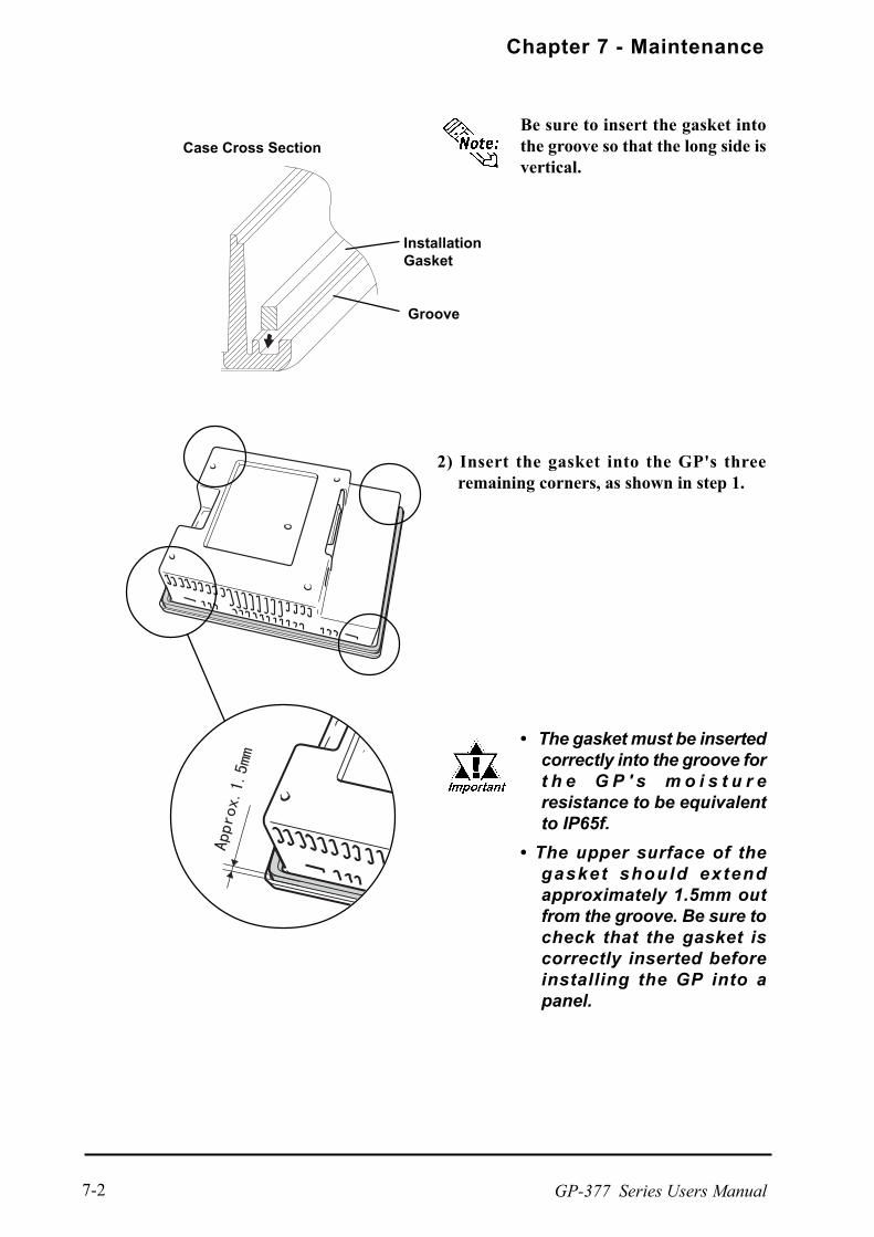
Chapter 7 - Maintenance
GP-377 Series Users Manual7-2
Be sure to insert the gasket intothe groove so that the long side isvertical.
Case Cross Section
2) Insert the gasket into the GP's threeremaining corners, as shown in step 1.
The gasket must be insertedcorrectly into the groove fort h e G P ' s m o i s t u r eresistance to be equivalentto IP65f.
The upper surface of thegasket should extendapproximately 1.5mm outfrom the groove. Be sure tocheck that the gasket iscorrectly inserted beforeinstalling the GP into apanel.
Groove
InstallationGasket

Chapter 7 - Maintenance
GP-377 Series Users Manual 7-3
7.2 Periodic Check Points
To keep your GP unit in its best condition, please inspect the following pointsperiodically.
GP Operation Environment
Is the operating temperature within the allowable range (0 oC to 50 oC )?
Is the operating humidity within the specified range (20% to 85% RH)?
Is the operating atmosphere free of any corrosive gasses?
Electrical Specifications
Is the input voltage appropriate (DC24V±15%) ?
Related Items
Are all power cords and cables connected properly? Have any become loose?
Are all mounting brackets holding the unit securely?
Are there many scratches or traces of dirt on the installation gasket?

Chapter 7 - Maintenance
GP-377 Series Users Manual7-4
When the unit's backlight burns out, the unit's status LED will turn orange. If theOFFLINE menu's "USE TOUCHPANEL AFTER BACKLIGHT BURNSOUT"feature is set to "NO", the GP's touch panel will be disabled*1 .
5.4.3 Setup Touchpanel
The GP-377 Series unit uses a CCFL, long-life type backlight. The actual life ofthe backlight however, will vary depending on the GP’s operating conditions, andreplacement may be required. The GP-377 Series backlight has a life of 30,000hours (appr. 3.4 years), when the backlight is lit continuously (time required forbrightness to fall to half its normal level).
*1 If "NO" has been selected for the OFFLINE menu's "FORCE RESET" feature,Touch-Panel operation is disabled.
Use the following table to check that you have ordered the correct backlight.
7.3 Changing the Backlight
• To prevent an electric shock, be sure the GP's power cordis unplugged from the power outlet prior to changing thebacklight.
• When the power has just been turned OFF, the unit andbacklight are still very hot. Be sure to use gloves to pre-vent burns.
• The backlight is very fragile. Do not touch the glass tubedirectly or try to remove its power cord. If the glass tubebreaks you may be injured.
WARNINGS
GP Backlight ModelGP377-LG11-24VGP377-LG41-24VGP377-SC11-24VGP377-SC41-24V
GP377L/S-BL00-MS
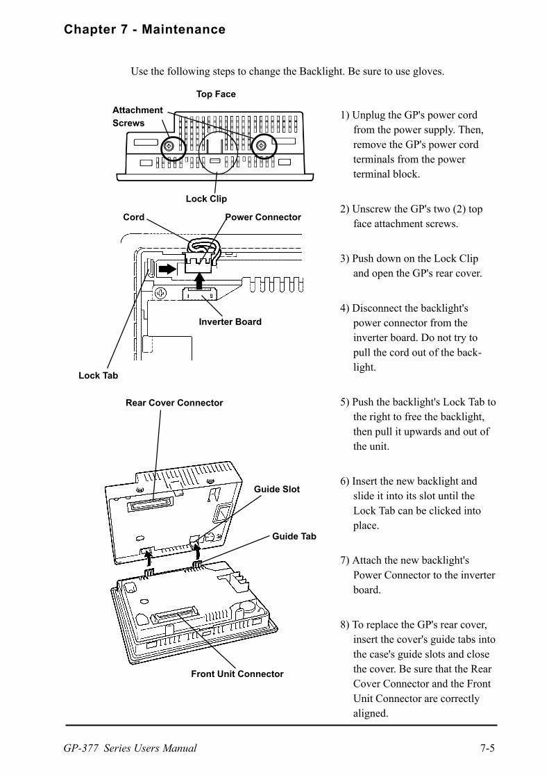
Chapter 7 - Maintenance
GP-377 Series Users Manual 7-5
Use the following steps to change the Backlight. Be sure to use gloves.
1) Unplug the GP's power cordfrom the power supply. Then,remove the GP's power cordterminals from the powerterminal block.
2) Unscrew the GP's two (2) topface attachment screws.
3) Push down on the Lock Clipand open the GP's rear cover.
4) Disconnect the backlight'spower connector from theinverter board. Do not try topull the cord out of the back-light.
5) Push the backlight's Lock Tab tothe right to free the backlight,then pull it upwards and out ofthe unit.
6) Insert the new backlight andslide it into its slot until theLock Tab can be clicked intoplace.
7) Attach the new backlight'sPower Connector to the inverterboard.
8) To replace the GP's rear cover,insert the cover's guide tabs intothe case's guide slots and closethe cover. Be sure that the RearCover Connector and the FrontUnit Connector are correctlyaligned.
Power ConnectorCord
Lock Tab
Front Unit Connector
Rear Cover Connector
Guide Slot
Lock Clip
Top Face
Inverter Board
Guide Tab
Attachment
Screws

Memo
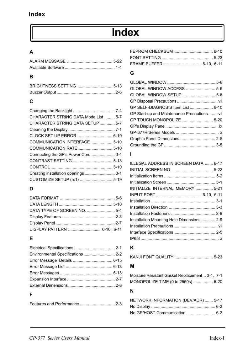
Index
GP-377 Series Users Manual Index-I
Index
A
ALARM MESSAGE ....................................... 5-22
Available Software ........................................... 1-4
B
BRIGHTNESS SETTING .............................. 5-13
Buzzer Output .................................................. 2-6
C
Changing the Backlight .................................... 7-4
CHARACTER STRING DATA Mode List ......... 5-7
CHARACTER STRING DATA SETUP ............. 5-7
Cleaning the Display ........................................ 7-1
CLOCK SET UP ERROR .............................. 6-19
COMMUNICATION INTERFACE................... 5-10
COMMUNICATION RATE ............................. 5-10
Connecting the GP's Power Cord .................... 3-4
CONTRAST SETTING .................................. 5-13
CONTROL ..................................................... 5-10
Creating installation openings .......................... 3-1
CUSTOMIZE SETUP (n:1) ............................ 5-19
D
DATA FORMAT ............................................... 5-6
DATA LENGTH .............................................. 5-10
DATA TYPE OF SCREEN NO. ........................ 5-4
Display Features .............................................. 2-3
Display Panel ................................................... 2-7
DISPLAY PATTERN ............................ 6-10, 6-11
E
Electrical Specifications ................................... 2-1
Environmental Specifications ........................... 2-2
Error Message Details .................................. 6-15
Error Message List ........................................ 6-13
Error Messages ............................................. 6-13
Expansion Interface ......................................... 2-7
External Dimensions ........................................ 2-8
F
Features and Performance .............................. 2-3
FEPROM CHECKSUM.................................. 6-10
FONT SETTING ............................................ 5-23
FRAME BUFFER................................. 6-10, 6-11
G
GLOBAL WINDOW ......................................... 5-6
GLOBAL WINDOW ACCESS ......................... 5-6
GLOBAL WINDOW SETUP ............................ 5-6
GP Disposal Precautions ................................... vii
GP SELF-DIAGNOSIS Item List .................... 6-10
GP Start-up and Maintenance Precautions ........ vii
GP TOUCH MONOPOLIZE........................... 5-20
GP's Display Panel ............................................. ix
GP-377R Series Models ..................................... x
Graphic Panel Dimensions .............................. 2-8
Grounding the GP............................................ 3-5
I
ILLEGAL ADDRESS IN SCREEN DATA ....... 6-17
INITIAL SCREEN NO. ................................... 5-22
Initialization Items ............................................ 5-2
Initialization Screen.......................................... 5-1
INITIALIZE INTERNAL MEMORY ............... 5-21
INPUT PORT....................................... 6-10, 6-11
Installation ....................................................... 3-1
Installation Direction ........................................ 3-3
Installation Fasteners ...................................... 2-9
Installation Mounting Hole Dimensions ............ 2-9
Installation Precautions...................................... vii
Interface Specifications ................................... 2-5
IP65f ................................................................... x
K
KANJI FONT QUALITY ................................. 5-23
M
Moisture Resistant Gasket Replacement .. 3-1, 7-1
MONOPOLIZE TIME (0 to 2550s) ................. 5-20
N
NETWORK INFORMATION (DEV/ADR) ....... 5-17
No Display ....................................................... 6-3
No GP/HOST Communication ......................... 6-3
Index
GP-377 Series Users ManualIndex-II
O
OBJ. PLC HAS NOT BEEN SETUP .............. 6-20
OFFLINE displays During RUN Mode ............. 6-3
ONLINE ERror Display .................................. 5-22
Optional Maintenance Items ............................ 1-5
Options ............................................................ 1-5
Overlapping Addresses ................................. 6-17
P
PLC COM. ERROR ....................................... 6-18
PARITY.......................................................... 5-10
PASSWORD SETUP(0-9999) ......................... 5-3
Periodic Check Points ..................................... 7-3
Placement of I/O Signal Lines ......................... 3-5
PLC PRIORITY ............................................. 5-19
PLC SETUP .................................................. 5-16
Possible Types of Trouble ............... 6-3, 6-4, 6-7
Power Input Terminal Block ............................. 2-7
Prevent Damage to the GP............................... viii
R
RECEIVE TIMEOUT ..................................... 5-11
REGISTRATION NO. (1-256) .......................... 5-6
Regular Cleaning ............................................. 7-1
RESET GP ON WRITE ERROR ................... 5-17
RETRY COUNT ............................................ 5-11
RUN Mode ...................................................... 6-1
S
SELF-DIAGNOSIS - Details ........................ 6-11
Safty Precautions ........................................... v, x
Screen Data or Project Data Related Problems ... 6-16
SCREEN TAG LIMIT EXCEEDED(max. of 384) . 6-19
SELF-DIAGNOSIS ........................................ 6-10
SELF-DIAGNOSIS-tandard Operation ............. 4-6
Serial Interface ................................ 1-4, 2-5, 2-7
SET UP I/O.................................................... 5-10
SET UP SCREEN.......................................... 5-22
SET UP TIME ................................................ 5-21
SET UP TOUCH PANEL ..................... 5-12, 5-15
SIO CHECK......................................... 6-10, 6-12
STAND-BY MODE TIME (0-255) ..................... 5-3
START TIME (0-255) ....................................... 5-3
STATION NO. (0-15) ..................................... 5-18
Status LED ...................................................... 2-7
Steps to run SYSTEM RESET....................... 5-12
Structural Specifications .................................. 2-1
SYSTEM AREA READ SIZE (0-256) ............. 5-16
SYSTEM AREA SETUP .................................. 5-4
System Area Size ............................................ 5-4
SYSTEM AREA START (DEV/ ADR) ............ 5-16
SYSTEM ENVIRONMENT SETUP ................. 5-3
SYSTEM ERROR .......................................... 6-15
SYSTEM ERROR ( 03 : x x ) ......................... 6-15
SYSTEM ERROR ( x x x : x x x : x x x ) .... 6-15
SYSTEM RESET MODE ............................... 5-12
SYSTEM SETUP ............................................. 5-3
T
TOOL CONNECTOR........................... 6-10, 6-12
Tool Connector ................................ 1-4, 2-7, 3-6
TOUCH BUZZER SOUND .............................. 5-3
TOUCH OPERATION MODE ........................ 5-12
TOUCH PANEL ................................... 6-10, 6-11
Touch Panel ..................................................... 2-7
Touch Panel / Clock Accuracy ......................... 2-4
Touch Panel Does Not Respond .............. 6-3, 6-9
Transferring Screen Data ................................ 4-8
Troubleshooting ............................................... 6-3
Turning the GP's Power ON ............................ 4-1
U
USE TOUCH PANEL AFTER BACKLIGHT BURN-
OUT ....................................................... 5-14
V
Validation List ................................................ 5-18
W
When OFFLINE mode displays during RUN
mode..................................................... 6-16
Wiring Cautions ............................................... 3-4
Wiring Precautions ............................................ vii