gn17 intellicenter advanced lab
TRANSCRIPT

GN17 – IntelliCENTER Advanced Lab
Presenter: Nino Martinez Low Voltage Motor Control Center Business


GN17 — IntelliCENTER Advanced Lab RSTechED 2006 Rockwell Software 3 of 66
GN17 — IntelliCENTER Advanced Lab
Contents
Before you begin ........................................................................................................................... 5 About this lab....................................................................................................................................5
Tools & prerequisites........................................................................................................................5
Introduction to the Lab Hardware................................................................................................ 6 E3 Electronic Overload.....................................................................................................................7
E1 Electronic Overload.....................................................................................................................8
PanelView Control ............................................................................................................................8
What’s New in IntelliCENTER Software..................................................................................... 10
Lab Selection ............................................................................................................................... 11
Section One – IntelliCENTER Introduction ............................................................................... 12 Connecting to the Motor Control Center (MCC) .............................................................................12
Elevation View: ...............................................................................................................................14
Monitor View...................................................................................................................................16
IntelliCENTER Documentation Features........................................................................................19
Spreadsheet View...........................................................................................................................22
Section Two: HMI Tags and Macro Automation ...................................................................... 25
Determining Lineup IDs or Device IDs ...................................................................................... 25 IntelliCENTER ID Program.............................................................................................................25
Start a RSView SE Project .............................................................................................................26
Configure Object with the Property Panel ......................................................................................27
Configure Objects using RSView Tags ..........................................................................................31

GN17 — IntelliCENTER Advanced Lab 4 of 66 RSTechED 2006 Rockwell Software
Section Summary ...........................................................................................................................36
More Tag Automation .....................................................................................................................37
Automating the Monitor Object from the Elevation View Display ...................................................38
Automating the Document Object from the Monitor Display ..........................................................41
Section Three: VBA Automation............................................................................................... 43 Adding an Elevation ActiveX control to a VBA UserForm. .............................................................44
Adding a Monitor ActiveX control to a VBA UserForm...................................................................46
Adding a Documentation ActiveX control to a VBA UserForm.......................................................46
Appendix One – Object Model.................................................................................................... 46
IntelliCenter Elevation View ActiveX Control ........................................................................... 46
IntelliCenter Monitor ActiveX Control........................................................................................ 46
IntelliCenter Document ActiveX Control ................................................................................... 46
IntelliCenter Spreadsheet ActiveX Control ............................................................................... 46

GN17 — IntelliCENTER Advanced Lab RSTechED 2006 Rockwell Software 5 of 66
Before you begin
IntelliCENTER Software allows the novice computer user to configure, collect data and troubleshoot an intelligent Motor Control Center – without requiring extreme expertise in industrial networks. As motor control devices become more complex, the traditional industrial electrician is challenged to maintain these devices. IntelliCENTER Software meets this challenge head-on by providing an intuitive, pre-configured interface to make this transition to higher technologies as simple as a few mouse clicks. IntelliCENTER ActiveX objects extend these features to HMI’s. The objects can be used to quickly generate elaborate HMI solutions. The objects also have an object model that allows full automation with VBA.
About this lab In the lab you will learn about advanced methods for creating HMI solutions with IntelliCENTER ActiveX objects. You will focus on automating the objects with HMI tags, macros and VBA. The time to complete this lab is based on which lab sections are completed.
This lab can be tailored to your needs. There are three sections to the lab and each will focus on a key area.
1. IntelliCENTER Introduction
2. Automation with HMI tags and Macros
3. Automation with VBA – Visual Basic for Applications
If you are new to IntelliCENTER Software, please look at the IntelliCENTER Introduction. Otherwise pick the automation section or sections you would like to complete.
Before starting a section, please read the Introduction to the lab hardware and the what’s new with IntelliCENTER Software.
Tools & prerequisites IntelliCENTER Software
RSView SE
RSLinx Classic
VBA experience

GN17 — IntelliCENTER Advanced Lab 6 of 66 RSTechED 2006 Rockwell Software
Introduction to the Lab Hardware
The lab hardware consists of two main pieces of equipment. The first box contains the Control Logix and PanelView.
The PanelView will be used to start and stop the devices located in the second box.
This lab will focus on the E3 (far right) and the E1 (second from the right) electronic overloads. As stated before, the PanelView will be used to start and stop the E3 and E1. The start/stop switches in this case are not programmed for control.

GN17 — IntelliCENTER Advanced Lab RSTechED 2006 Rockwell Software 7 of 66
The bottom right switch will be used to connect the fan load to either the E3 or the E1.
For this lab, place the upper left switch in “Local” mode and the upper right switch in “Hand” mode.
E3 Electronic Overload The E3 is an electronic overload relay that is highly configurable, has built-in DeviceNet and DeviceLogix.
Notice the input LEDs located on the front of the E3. These LEDs illuminate when there is a 24V signal on the inputs. There are four inputs on the E3.
Notice the output lights on the E3. There are two output contacts that can be operated by remote control on the E3. These contacts are typically used to energize the coil on the contactor. In a reversing starter both contacts are used. These outputs are labeled “OUT A” and “OUT B” on the overload. These outputs will be energized during this lab because the E3 will be operated by the ControlLogix.
The blue button is a combination TEST/RESET button. If the E3 trips, it can be manually reset by pressing this button. (The E3 can also be remotely reset by a command from the PanelView.) If the E3 starter unit is operating and this button is pushed, then the E3 will execute a test trip. Some models of the E3 require the reset button to be held for three seconds before tripping.

GN17 — IntelliCENTER Advanced Lab 8 of 66 RSTechED 2006 Rockwell Software
There is a trip contact inside the E3 that breaks the coil circuit in case of an overload or test trip. This contact is an addition to the two remote control contacts. See page 2-20 of the E3 User Manual for a simple diagram of a control circuit using the E3 overload.
E1 Electronic Overload The E1 Electronic overload relay has the optional DeviceNet communication module connected to the base relay. This provides a very cost effective solution where network communications is desired without a significant cost increase over a standard eutectic overload.
Notice the input LEDs located on the front of the E1. These LEDs illuminate when there is a 24V signal on the inputs. The E1 has two inputs.
Notice the output lights on the E1. There is one output contacts that can be operated by remote control on the E1. This contact is typically used to energize the coil on the contactor. This output is labeled “OUT A” on the overload. This output will be energized during this lab because the E1 will be operated by the ControlLogix.
The blue button is a reset only button. The trip indicator will by yellow if a trip occurs. The full load amp setting is set via a rotary switch on the overload.
PanelView Control The PanelView has a series of screen to control each of the devices in both cases. For this lab, select the “Basic DeviceNet” from the main menu.

GN17 — IntelliCENTER Advanced Lab RSTechED 2006 Rockwell Software 9 of 66
Next you will see a button for each device in the cases. As stated before, this lab will focus on the E3 and the E1.
Select either the E3 or E1.
Selecting “Basic Menu” will always return to the list of devices. Remember to set the bottom right load switch to the correct device to connect the fan load.

GN17 — IntelliCENTER Advanced Lab 10 of 66 RSTechED 2006 Rockwell Software
What’s New in IntelliCENTER Software
The latest version of the software, Version 2.0, integrates a new Elevation View.
The new Elevation View keeps the existing status indicators to very quickly identify the operation of the Motor Control Center (MCC). Additionally the view can by dynamically sized to increase or decrease the number of sections displayed in the view. New features include the ability to drag and drop units and sections to very quickly and easily move units and sections within a lineup or to another lineup. Product images very quickly identify the type of motor control device in each unit. Each unit or section description is editable from the Elevation View. Finally, units and sections can be inserted or deleted.

GN17 — IntelliCENTER Advanced Lab RSTechED 2006 Rockwell Software 11 of 66
Lab Selection
Now you have the choice of which lab sections to work through.
Section One: IntelliCENTER Introduction – Page 12
Section Two: Automation with HMI tags and Macros – Page 25
Section Three: Automation with VBA – Page 43
This two hour lab may not be long enough to complete all three sections. If you are familiar with IntelliCENTER please start with section two or three depending on your greater interest.
GN17 — IntelliCENTER Advanced Lab 12 of 66 RSTechED 2006 Rockwell Software
Section One – IntelliCENTER Introduction
Connecting to the Motor Control Center (MCC) The purpose of this section is to establish communication between the computer and the IntelliCENTER demo.
IntelliCENTER software provides a window into the setup, operation and troubleshooting of the IntelliCENTER MCC. This software is designed to be intuitive.
The customer does not have to call his or her networking expert (usually an engineer), to provide maintenance and troubleshooting for an IntelliCENTER MCC. As will be shown, a novice computer user can quickly access critical information and easily change operational parameters on the intelligent MCC.
IntelliCENTER software is pre-configured for ease of use. The advantage to using pre-configured software is there is no need to program screens, animate push buttons, assign tag numbers, etc. Creating an interface between network data and the PC can be an expensive task. Maintaining this interface when changing units can cause delays. IntelliCENTER uses pre-configured screens for each type of device in the MCC. Adding a unit is as simple as using the configuration CD that is provided with the new unit.
1. Double-click on the IntelliCENTER software icon on the desktop.
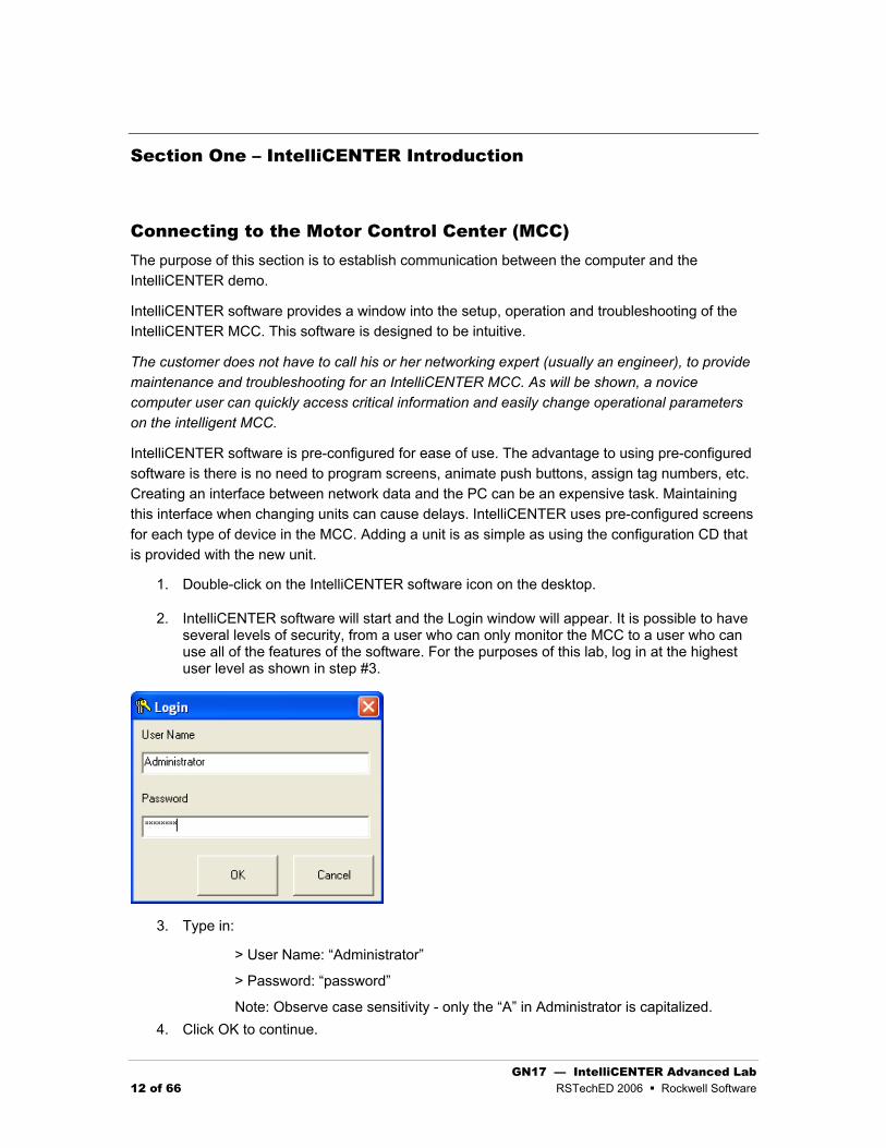
2. IntelliCENTER software will start and the Login window will appear. It is possible to have several levels of security, from a user who can only monitor the MCC to a user who can use all of the features of the software. For the purposes of this lab, log in at the highest user level as shown in step #3.
3. Type in:
> User Name: “Administrator”
> Password: “password”
Note: Observe case sensitivity - only the “A” in Administrator is capitalized. 4. Click OK to continue.

GN17 — IntelliCENTER Advanced Lab RSTechED 2006 Rockwell Software 13 of 66
Connecting the PC to the MCC
After logging into the software, a window appears asking which “Workspace” to use. A Workspace defines what screens to open, which MCC is connected, etc. Since a workspace has never been set up, choose “IntelliCENTER” under the New tab and click Open. Further information on workspaces can be found in the help file.
IntelliCENTER software uses Rockwell Automation exclusive NetLinx architecture. This means that, with a single software package, the user can connect at various levels within the facility's network architecture and navigate to a desired device – in this case, a motor control center. It is possible to use IntelliCENTER software to view multiple MCC lineups within a facility.
It is necessary to specify which MCC the IntelliCENTER software is connecting to. Selecting the MCC is a two step process – specifying which MCC and then specifying the network path to this MCC.
To select the MCC, use the drop-down menu to choose the MCC lineup called "HandsOn Demo Cases 2". Click Next to continue.
The next window allows the user to specify where (on the network) to look for the devices in the selected lineup.
If the correct network path is displayed, click Finish otherwise click the RSWho button to select the correct network path.

GN17 — IntelliCENTER Advanced Lab 14 of 66 RSTechED 2006 Rockwell Software
Verify that the right pane has an E3 at node 5 and an E1 at node 4. If these devices are not in the network, please open RSLinx Classic RSWho. If you cannot communicate to the devices ask for assistance.
Press OK to continue.
Connection Types:
Express
Express communication type assumes that no changes have taken place in the lineup since the last time the computer was connected. That is, it is assumed that the database on the computer is correct. IntelliCENTER Software will quickly load the Elevation View and start polling devices. This is the fastest connection.
Intermediate
The Intermediate type of connection checks all the units as they appear in the computer's database against what is found in the network. Only those units that are expected to be on the network are polled. This type of connection takes longer than the Express connection. This connection is typically done when a device has been replaced.
The first time connecting to the devices, use Intermediate. If you reconnect in the future, use an Express connect.
Once the MCC and the method of connection are chosen, click Finish.
Elevation View: In a few seconds a graphical view of the MCC will appear.

GN17 — IntelliCENTER Advanced Lab RSTechED 2006 Rockwell Software 15 of 66
1. The Elevation View can be resized by clicking and dragging a corner of the window. This is a useful feature when viewing multiple lineups. Point to the lower right hand corner of the Elevation View screen with the mouse and click-and-drag to scale this view. Notice that if the proportions of the view become too narrow, only one section of the MCC is visible; however, it is possible to use the scroll bar to scroll through the views. Also note that when the units become too small, the status lights are replaced with the door changing to the color of the status light.
2. Without clicking, move the mouse over various units of the MCC. The nameplate data is now displayed in a tool-tip box. The tool-tip also reports the unit status.
3. Single click (do not double-click) on a unit in the MCC. Notice the device is highlighted with a black border. Selecting a single unit in a lineup tells IntelliCENTER software that the user only wants data for the selected unit. This selection feature is useful when looking up spare parts, events in the event logger and documentation. To select the entire MCC, click inside the Elevation View window but not on any particular unit.
4. Observe the status lights on all units. If the power to all the units is on, the lights should all be blue, indicating that they are ready to run. Select the E1 on the PanelView and start the motor. Make sure the motor selector switch is on E1. Observe the change in the status light on the Elevation view. Turn the selector switch to Off to stop the motor.
5. The two line description and location fields can be edited while inside the Elevation View. Double click on the E3 description:

GN17 — IntelliCENTER Advanced Lab 16 of 66 RSTechED 2006 Rockwell Software
The description field changes and now can be edited. Change the second line to include a motor name. The location text can also be edited.
6. Units can now be moved in the lineup by using standard Windows drag and drop methods. Click and drag the E3 from section two to section one. When you release the mouse, notice that the sections resize to display all the devices in the new section. Move the E3 back to section two.
7. The Elevation View now has the feature to insert and delete MCC Units. This is accomplished with the right-click menus.
8. When edits have been made to the Elevation View, the Apply button will be enabled and can be used to save the edits.
Causing a Fault
1. Press the blue TEST/RESET button on the E3 solid-state overload relay to simulate a trip. Note the color of the indicator on this unit now. Depending on which release of E3 firmware the device has, it may be necessary to press and hold the Test/Reset button for three seconds in order to create a test trip condition.
2. Press the blue TEST/RESET button again to reset the test trip.
It has been easy to connect and establish communications with an MCC using IntelliCENTER software. Even a novice user can log into an MCC and see critical process data with a few clicks of the mouse without being a networking expert!
Monitor View The purpose of this section is to explain the features and functionality of the Monitor View. From the Monitor View, the user can observe process data and configure device settings.
Suppose a fault is observed on the E3 on the Elevation View:
1. Press (and hold if needed) the TEST/RESET button on the E3 overload to create a test trip condition. Observe the red fault light on both the E3 status LED and the corresponding unit on the Elevation View. Given the scenario of a red fault light on a unit and having some Internet experience, what would the user do to get more information on this unit?
Answer: Double-click on that unit.
2. Double-click on the E3 in the Elevation View to see the Monitor View screen. Note the four quadrants of the Monitor View screen (Part Description, Trend Graphs, Gauges, I/O - Parameters). All monitor views, regardless of unit type, will have this same basic four-quadrant type of layout. This is a pre-configured screen.

GN17 — IntelliCENTER Advanced Lab RSTechED 2006 Rockwell Software 17 of 66
3. Under the Parameters section of the Monitor View, notice the Trip Status is highlighted. The fault will be listed in this area. (If the Trip Status parameter is not visible, contact your instructor.)
4. Reset the test trip (press the blue button) and observe the Trip Status.
5. Now observe the I/O status in the lower right hand quadrant of the Monitor View. Operate the H-O-A (Hand-Off-Auto)switch. Note which input point (on the E3 overload relay) that the Hand and Auto mode is connected.
6. Place the H-O-A switch into Hand mode and start the E3 from the PanelView. Note which output point (on the E3) that the starter coil is connected to.
7. Notice the gauges and trend graphs on the Monitor View. There are three analog gauges and two trend graphs on the Monitor View for all devices. When the Monitor View is opened for the first time, factory default parameters for each gauge and graph are displayed.
What is a Parameter?
All DeviceNet components can store and report data. We refer to the individual pieces of data as parameters. The data can be divided into three categories as noted below:
Process data:
o Amperes on Line 2
o Ground Fault Current
o Time Until Trip Occurs
Configuration data:

GN17 — IntelliCENTER Advanced Lab 18 of 66 RSTechED 2006 Rockwell Software
o Trip Class
o Motor Full Load Amps (FLA)
o Delay Before Trip
Device specific data :
o Firmware Revision
o DeviceNet Node Address
o Network Baud Rate
IntelliCENTER software will allow the user to change configuration data in the second group above.
The E3 has more than 70 parameters. For more information, refer to the E3 manual, chapters 5-7 for a complete description of these parameters.
Changing Parameters Shown in Monitor View
1. Observe the middle analog gauge in the Monitor View. The gauge is displaying the ground fault current measured by the E3 overload relay.
2. Right click on this gauge. A menu will appear. Click on "Change Parameter Monitored" and the "Edit Parameter" window will appear.
3. Click the down-arrow under Parameter Name. Use the slider to scan the all the parameters stored by the E3.
4. Pick Parameter 5, “L1 %fla” (Line 1 - percent full load amps). Change Scaling “Max.
Value” to 100 and click Apply. Notice the new legend on the analog gauge. Note also the new meter range.
In the bottom right quadrant of the Monitor View next to the I/O, there is a group of parameters with their corresponding values. This list is divided into two parts, Data and Parameters. These are places to display eight more of the E3’s Parameters. (The division between Data and Parameters is simply a way for the user to organize the data shown. Data could be information on the process, percent thermal capacity used. Parameters could be information on how the E3 is configured, delay before the trip. It is possible to use a data field for a parameter or vice versa, if necessary.)
Changing a Parameter Value
IntelliCENTER software will allow the user to change configuration data of the device. (Note that it

GN17 — IntelliCENTER Advanced Lab RSTechED 2006 Rockwell Software 19 of 66
is not possible to change the value of a parameter that is measured by the E3, such as "Line 1 Current." "Line 1 Current" is process data and can only be changed by changing the amount of current actually passing through Line 1.) The software will not allow the user to attempt to change the value of a process data parameter.
1. Click on the white box next to FLA Setting. Note, information given for the minimum and maximum allowable values. This exercise shows how devices can be configured using IntelliCENTER software. Notice there are some attributes that IntelliCENTER software cannot change, such as network baud rate or device address. RSNetworx would be required for these changes.
2. Close the Monitor view for this unit (Click on the X in the upper right hand corner). If any edits were made to the Monitor view, the software will prompt to save the edits. Also, if the Monitor View is closed while the trends are running, the software will prompt you to make sure you want to exit. Trend data is lost when the Monitor view is closed.
IntelliCENTER Documentation Features The purpose of this section is to provide additional information to aid in setting up and troubleshooting the MCC. In addition to the monitoring, charting and configuration capabilities demonstrated previously, IntelliCENTER software provides more useful documentation information. From the Elevation View, single-click on Unit #1 (bucket 2A), the E3 unit. Notice this unit now has a darker border around it.
Manuals
Locating the Proper Manual
1. From the menu select Documentation >Manuals. The Manuals window will appear and because the E3 unit was selected, this unit is displayed in the left pane and all the E3

GN17 — IntelliCENTER Advanced Lab 20 of 66 RSTechED 2006 Rockwell Software
related documents appear in the right pane.
2. Click on the last item in the list, the E3 User Manual, then click the “View File” button below. Adobe Acrobat Reader will start and display the E3 manual. This manual should be the same as the hard copy at the workstation. (Sometimes the hard copy at the work station will be a later revision – when manuals get lost, they are replaced with the newest revision. The benefit of IntelliCENTER software is that the manual that directly applies to the version of the installed device is always available.)
3. Close Acrobat and return to the Manuals list.
4. Click the “Show all Units” button. Notice that the left pane now shows all the MCC units. In the left pane, click on a different Unit. The right pane now lists documents pertaining to that unit.
Drawings
Locating Drawings
1. At the Elevation View, single-click on the E3, so that its border is bold. From the menu select Documentation > Drawings. The wiring diagrams for the E3 are listed. Click on the only drawing in the right pane. Next click the “View File” button.

GN17 — IntelliCENTER Advanced Lab RSTechED 2006 Rockwell Software 21 of 66
2. A program DWG TrueView, which is a CAD document viewer, starts and the wiring diagram appears.
Note: DWG TrueView is not a full CAD program - it is only a viewer.
Maximize this window. Note the drawing may be too small to read. To adjust the view, select one of the magnifiers from the tool bar. The second magnifier (Zoom Window) selects and zooms in on a particular area of the print.
The hand tool (Pan Realtime) will move the wiring diagram within the window so that desired parts of the diagram can be viewed. Press escape (ESC) to exit panning
Close DWG TrueView and return to IntelliCENTER.
Spare Parts
IntelliCENTER software comes with a list of major spare parts for each unit. (Note: This list is not a complete bill of materials for the unit.)
1. Select the E1, on the Elevation View by single-clicking it. From the menu select Documentation > Spare Parts. Notice the spare parts are listed.

GN17 — IntelliCENTER Advanced Lab 22 of 66 RSTechED 2006 Rockwell Software
2. Close the “Spare Parts” window. Deselect the E1 by clicking somewhere in the Elevation View, but not on a unit. Re-open the spare parts list (Documentation > Spare Parts) and note the spare parts for all the units are shown.
3. Observe all the columns in the spare parts view. Notice the Rockwell Automation part number is listed. This can save a lot of time when calling a distributor.
4. Note the four “User” fields. The user may enter data here. For example, some customers keep a supply of spares on hand. The bin number or the stockroom’s part number can be entered in one of these fields. The user field titles can also be changed to any text desired. From the menu select Edit > Edit User Fields.
5. Also note that the list price is shown. Please see disclaimer at the bottom of the window.
6. Close the “Spare Parts” window.
Event Logger
When IntelliCENTER software is running, it has the capability to automatically record certain events such as trips, warnings and parameter changes. A manual event may also be entered to record important actions.
From the menu select View > Events. Scan the event log to see the activities that have already been performed during this lab. If a unit is selected on the Elevation View, only the events associated with the unit are displayed. If there is no unit selected, all events will be shown. Look for events related to the lab activity so far.
Spreadsheet View In addition to the Elevation View and the Monitor View, there is a third view that gives the user a concise overview of the MCC, called the Spreadsheet View. The Spreadsheet View is a composite of information from all the units in tabular form. The Spreadsheet view provides the ability to edit settings that normally do not change. This includes node number, network number,
GN17 — IntelliCENTER Advanced Lab RSTechED 2006 Rockwell Software 23 of 66
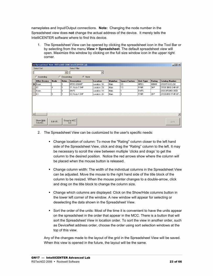
nameplates and Input/Output connections. Note: Changing the node number in the Spreadsheet view does not change the actual address of the device. It merely tells the IntelliCENTER software where to find this device.
1. The Spreadsheet View can be opened by clicking the spreadsheet icon in the Tool Bar or by selecting from the menu View > Spreadsheet. The default spreadsheet view will open. Maximize this window by clicking on the full size window icon in the upper right corner.
2. The Spreadsheet View can be customized to the user's specific needs:
Change location of column: To move the "Rating" column closer to the left hand side of the Spreadsheet View, click and drag the “Rating” column to the left. It may be necessary to scroll the view between multiple ‘clicks and drags’ to get the column to the desired position. Notice the red arrows show where the column will be placed when the mouse button is released.
Change column width: The width of the individual columns in the Spreadsheet View can be adjusted. Move the mouse to the right hand side of the title block of the column to be resized. When the mouse pointer changes to a double-arrow, click and drag on the title block to change the column size.
Change which columns are displayed: Click on the Show/Hide columns button in the lower left corner of the window. A new window will appear for selecting or deselecting the data shown in the Spreadsheet View.
Sort the order of the units: Most of the time it is convenient to have the units appear on the spreadsheet in the order that appear in the MCC. There is a button that will sort the Spreadsheet View in location order. To sort the view in another order, such as DeviceNet address order, choose the order using sort selection windows at the top of this view.
Any of the changes made to the layout of the grid in the Spreadsheet View will be saved. When this view is opened in the future, the layout will be the same.

GN17 — IntelliCENTER Advanced Lab 24 of 66 RSTechED 2006 Rockwell Software
3. Notice the nameplates given for each unit in the demo case.
How they typically look: FVNR Starter With E3 Overload
Adding Nameplate Data
The Spreadsheet View can be used to add nameplate data (for the individual units), that will show up on the Elevation View.
1. Look for the Nameplate columns in the Spreadsheet View. If they are not present use steps 2-4 to display these columns. If they are shown, skip to step 5.
2. Click on the “Show/Hide” columns.
3. Scroll down to the fields for Nameplates 1 through 3.
4. Check the three boxes in the visible column next to Nameplates 1 through 3, then click “OK.”
5. Scroll over the spreadsheet until the new columns are visible.
6. Just for reference, go back and look at the Elevation View. Notice there is some information on each unit. Add some additional information to Nameplate 3. Click Apply to save the changes. Return to the Elevation View to see the changes. Remember the nameplate data only shows up on the tool tips.

GN17 — IntelliCENTER Advanced Lab RSTechED 2006 Rockwell Software 25 of 66
Section Two: HMI Tags and Macro Automation
Determining Lineup IDs or Device IDs
The IntelliCENTER database uses IDs or GUIDs (Globally Unique IDs) to uniquely identify each piece of data stored in the database. Each lineup, device, drawing, manual, spare part and event have IDs. The ICLineupID and ICDeviceID properties need these values to automate the objects.
IntelliCENTER ID Program The IntelliCENTER ID program can be used to get the lineup or device IDs from the database. From the Start menu select All Programs > IntelliCENTER > IntelliCENTER ID.
Select the desired lineup in the left window. The selected lineup’s ID will be displayed in the text box ICLineupID. A copy button will copy this ID onto the clipboard. As a lineup is selected, all the MCC Units (or devices) are displayed in the right window. As a device is selected its ID will be displayed in the text box ICDeviceID.

GN17 — IntelliCENTER Advanced Lab 26 of 66 RSTechED 2006 Rockwell Software
An export button will export the selected lineup into a CSV (Comma Separated Variables) text file. This text file can be read via VBA code into an array for programmatic reference. Sample code for this function is provided. This will be covered in section three of this lab exercise.
Start a RSView SE Project
1. Start RSView Studio
From the Start menu, Select Programs > Rockwell Software > RSView Enterprise > RSView Studio.
2. Select SE Stand-alone Project
3. Select the existing project IntelliCENTER RSTechED 2006 and click Open.

GN17 — IntelliCENTER Advanced Lab RSTechED 2006 Rockwell Software 27 of 66
4. Create a new graphic display
5. In this graphic display, insert an IntelliCENTER Elevation View ActiveX object
From the menu select Objects > ActiveX Controls…
In the graphic display, click and drag to size the ActiceX object.
Scroll and select ICenter_Elevation.ElevationActiveX and click OK.
Note the other IntelliCENTER ActiveX objects that are available – Document, Monitor and Spreadsheet. These will be used in later excercises.
Configure Object with the Property Panel
1. The simplest way to configure this object would be to set it properties manually.
Click the Elevation View object to select it.

GN17 — IntelliCENTER Advanced Lab 28 of 66 RSTechED 2006 Rockwell Software
Right click and select Properties, or from the menu select Edit > Properties
On the General tab are the properties that need to be configured. A lineup and a language are the only properties to be selected.
2. Select the lineup “RSTechEd 2006 IntelliCENTER Lab”
3. Select the Language as “English”
4. Save the display. Name it ElevationView
5. Test the Elevation View Object by selecting from the menu View > Test Display
The display should show the following:

GN17 — IntelliCENTER Advanced Lab RSTechED 2006 Rockwell Software 29 of 66
5. Communications to the MCC is via RSLinx Classic. If the RSWho path to the MCC has not been configured, the following window will appear:
Click RSWho to configure the communications path.
After opening the RSWho,
select the AB_ETH-1, Ethernet Driver;
select the 1756-ENBT device;
select the backplane;
select the 1756-DNB;
select the A, DeviceNet Network.
Click OK to select the path.
The devices should all appear in the right window. If none appear, call one of the instructors.
6. Once a communications path is selected, it is stored. Each time this same lineup is communicated to, the stored path will be used. This path can be reset with a program called ICPreferences. Click OK to accept the network path.
7. When done testing, select from the menu View > Edit Display. The object will continue to display the sections. Close and reopen the display to return to a blank view.

GN17 — IntelliCENTER Advanced Lab 30 of 66 RSTechED 2006 Rockwell Software
8. ICPreferences Program
From the Start menu select All Programs > IntelliCENTER > ICPreferences
Before any changes can be made, log on as the Administrator. The default password is password. Once logged on, select the Network Paths tab.
Select the RSTechED 2006 IntelliCENTER Lab in the network dropdown box. Click Clear to reset the path for this lineup. Next time any object is run for this lineup, the window to select the network path will appear again.
Clearing a network path is only needed if the RSWho path to a network has changed.
ICPreferences can also be used to configure other options within IntelliCENTER. For more information on this, refer to the IntelliCENTER help file.

GN17 — IntelliCENTER Advanced Lab RSTechED 2006 Rockwell Software 31 of 66
Configure Objects using RSView Tags
1. Create two tags to store the lineupID and language
Open the HMI Tags window.
Create an IntelliCENTER Folder by selecting Edit > New Folder from the menu. If the new folder does not appear, right-click and select refresh all. The folder is displayed in the lower left window.
Add the following tags in the IntelliCENTER folder
• ElevationLineupID, String, 50 character, type = memory
• Language, String, 20 character, type = memory
We will use these tags to configure the Elevation View object.
2. Return to the Elevation Display
Delete the Elevation View ActiveX. Insert a new Elevation View ActiveX
Open the property panel (Right-Click, Properties)
Select the Connections Tab
Configure the property ICLineupID to use tag IntelliCENTER\ElevationLineupID
Configure the property ICLanguage to use tag IntelliCENTER\Language

GN17 — IntelliCENTER Advanced Lab 32 of 66 RSTechED 2006 Rockwell Software
Select the Common tab and name the control ElevationActiveX_1.

GN17 — IntelliCENTER Advanced Lab RSTechED 2006 Rockwell Software 33 of 66
After programmatically changing any properties, the Show() method must be called.
To do this, open the display settings for the Elevation View display. Select the Behavior tab and program a startup command that calls the show event. The timing of a start up command will cause some problems with IntelliCENTER objects when using macro code. The start up command will run before the Elevation View object is initialized. To accommodate this, first pause for three seconds, then call the Show() function.
Hint: First program a pause for three seconds. Next use the Invoke command. The display is Me, the object is the name of your Elevation View object and the method is Show(). Make sure each command is separated with a semi-colon.
The pause is only needed when using macro programming with the IntelliCENTER objects. If VBA code is used, this will not be necessary.
The final start up command is: Pause 3;Invoke Me.ElevationActiveX_1.Show()
3. Next create two macros. Each macro must set the Lineup ID and the language. Both macros will use the same LineupID. Macro 1 will set the language to “spanish” and macro 2 will set the language to “french”.
Each macro must then load the Elevation View display.
If you need Help on macros, see the RSView SE help file. Select the index macros, then select syntax.
The LineupID’s can be found with the IntelliCENTER ID program discussed on page 25 of this lab exercise.

GN17 — IntelliCENTER Advanced Lab 34 of 66 RSTechED 2006 Rockwell Software
Macros:
Macro1 Spanish:
Set IntelliCENTER\Language "spanish"
Set IntelliCENTER\ElevationLineupID "75C625BA-C4BD-40CC-9760-82B35BC6B74F"
Display Elevation
Macro2 French:
Set IntelliCENTER\Language "french"
Set IntelliCENTER\ElevationLineupID "75C625BA-C4BD-40CC-9760-82B35BC6B74F"
Display Elevation
4. Now add two buttons to the existing display called Main.
Label the second button “Load French Elevation View” and link its press action to the correct macro. The Command Wizard for selecting a macro follows:
Label the first button “Load Spanish Elevation View” and link its press action to the correct macro. The final press action for this button follows:

GN17 — IntelliCENTER Advanced Lab RSTechED 2006 Rockwell Software 35 of 66
Save the Main Display.
5. Open the Elevation View Display.
To allow multiple copies of the Elevation View display, open the Display Settings (Edit > Display Settings from the menu) and select the box Allow Multiple Running Copies. Also set the Display Type to Overlay.
6. Run the SE Client to test each button on the Main Display. To run the SE Client select from the menu, Tools > Run SE Client. Pressing each button on the Main Display should open a new Elevation View Display. One will be in French, the other in Spanish.
To run the SE Client, a CLI file is needed. This file should be selected when you start the client. The file name and location is :
C:\Documents and Settings\All Users\Documents\RSView Enterprise\SE\Client\IntelliCenter.cli
The CLI file and all the security has been set up for each student workstation. If you are experiencing any problems running the SE Client, please ask one of the instructors.
Click on each button. Each will load the same Elevation View, one legend will be in Spanish and the other in French.

GN17 — IntelliCENTER Advanced Lab 36 of 66 RSTechED 2006 Rockwell Software
Section Summary This first exercise has shown how simple it is to automate the IntelliCENTER objects using tags and macros. You may have noticed that if you have many devices, you will have to program many macros. In the next section we will show other methods to significantly reduce the number of macros needed.

GN17 — IntelliCENTER Advanced Lab RSTechED 2006 Rockwell Software 37 of 66
More Tag Automation In this section we will look at automating the display of the IntelliCENTER monitor object. The monitor object is designed to show a lot of detailed information about a device in a preconfigured view. The monitor object is also very helpful in troubleshooting and diagnosing problems. Here is a sample of the monitor object:
GN17 — IntelliCENTER Advanced Lab 38 of 66 RSTechED 2006 Rockwell Software
Automating the Monitor Object from the Elevation View Display The device that has been selected in the Elevation View will be the device to be monitored. The Elevation View object has a property call ICCurrentDeviceID, which is the ID of the selected device. If no device is selected, this property will return an empty ID. The returned ID will be used to set the ICDeviceID of the Monitor object.
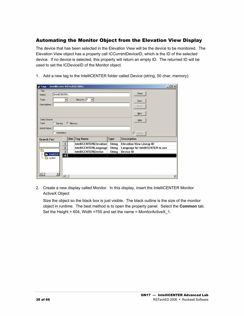
1. Add a new tag to the IntelliCENTER folder called Device (string, 50 char, memory)
2. Create a new display called Monitor. In this display, insert the IntelliCENTER Monitor ActiveX Object
Size the object so the black box is just visible. The black outline is the size of the monitor object in runtime. The best method is to open the property panel. Select the Common tab. Set the Height = 604, Width =755 and set the name = MonitorActiveX_1.

GN17 — IntelliCENTER Advanced Lab RSTechED 2006 Rockwell Software 39 of 66
Select the Connections Tab
Configure the property ICLineupID to use tag IntelliCENTER\SystemViewLineupID
Configure the property ICDeviceID to use tag IntelliCENTER\Device
If you do not connect any tag to the Language it will default to the IntelliCENTER Software setting in ICPreferences.
Select the Common Tab. Deselect the Focus Highlight and the Pointer Highlight check boxes. This will prevent the borders from lighting up when the controls are selected or the mouse moves over the object. Close the properties window.
Open the Display Settings for the Monitor Display. Set the display type to overlay. Select the Behavior Tab. Create a Startup Command that calls the Monitor object’s Show()

GN17 — IntelliCENTER Advanced Lab 40 of 66 RSTechED 2006 Rockwell Software
method, just as was done for the Elevation View Display. Remember to first use a three second pause. The final startup command is: Pause 3;Invoke Me.MonitorActiveX_1.Show()
3. Open the Elevation View Display
Add a button and make its caption “Load Monitor View”
As this button is pressed, we will read the ICCurrentDeviceID property from the Elevation View object and store this in the tag IntelliCENTER\Device.
To read the ICCurrentDeviceID, program the Press Action with an Invoke command. The display is Me, the object is the Elevation View object name, and the property is ICCurrentDeviceID(). Then select “set tag to value from object”. The tag to set will be IntelliCENTER\Device.

GN17 — IntelliCENTER Advanced Lab RSTechED 2006 Rockwell Software 41 of 66
Once complete, add a second Action to display the monitor view.
The final press action is: Invoke IntelliCENTER\Device = Me.ElevationActiveX_1.ICCurrentDeviceID();Display Monitor
4. Test the application. Open the Elevation View. Click one of the devices with an icon. Next click the Load Monitor View Button. If you select one of the units without an icon, or if you select no unit, the Monitor object will display an error.
Let’s review what has been accomplished so far. Two displays have been created. One for the Elevation View and another for the Monitor View. From these two views we can see any lineup and any device in that lineup. Two displays and a little macro code is all that is needed to create a simple but very functional solution.
The next step will be to modify the monitor view to include buttons for drawings, manuals and spare parts. This will require only one display with the IntelliCENTER document ActiveX object. The information needed for the document object will come from properties of the monitor object.
Automating the Document Object from the Monitor Display For this last part of this section, build upon what has already been programmed .
1. Create a display and insert the document ActiveX.
2. Create new tags for LineupID, DeviceIDConnect and DisplayType. Connect the required properties to these new tags.
3. Add three buttons to the monitor display. One for drawings, one for manuals and one for spare parts.

GN17 — IntelliCENTER Advanced Lab 42 of 66 RSTechED 2006 Rockwell Software
4. Program each of the above buttons to do the following:
Get lineup and device IDs from the monitor object and store these values in the tags created.
Load the document display by pausing threes seconds and then calling the show event.
Hint: The document ActiveX has a new property call ICDisplayType. This determines if drawings, manuals, spares or events are displayed. Reference the object model in Appendix 1 for details.
5. Test the design.
When this step has been successfully accomplished, the core functionality of the IntelliCENTER application has been recreated in RSViewSE. The user now has a very robust set of displays for all lineups and all devices.
The final code will look like:
Button code:
Invoke IntelliCENTER\Document_LineupID=Me.MonitorActiveX_1.ICLineupID();
Invoke IntelliCENTER\Document_DeviceID=Me.MonitorActiveX_1.ICDeviceID();
Set /V IntelliCENTER\DisplayType "cad";
Display Document
Note: The Set command will set a tag with a value. For this example, DisplayType is a string, so the Set command wizard needs to set a string value. Use “cad” for the Drawings button, “manual” for the Manuals button and “spares” for the Spare Parts button.
Display code:
Pause 3;Invoke Me.DocumentActiveX_1.show()

GN17 — IntelliCENTER Advanced Lab RSTechED 2006 Rockwell Software 43 of 66
Section Three: VBA Automation
In this section we will look at automating IntelliCENTER ActiveX objects with Visual Basic for Applications (VBA).
To accomplish this, we will place the ActiveX objects on User Forms instead of display screens. The design of a VBA solution will be similar to the macro solution. From the Main Display, a button will load a VBA UserForm with a Elevation ActiveX. The Elevation will load a Monitor View. Lastly, the Monitor View will load the document view for either drawings, manuals or spare parts.
This solution is nearly identical to the macro automation, but there are a few key differences:
1. This solution will have all the programming in VBA. With a macro solution, some code was in macro, some was in button clicks and finally some was in display start up code.
2. This solution will not require the three second paused needed before calling the Show() Method of the objects.

GN17 — IntelliCENTER Advanced Lab 44 of 66 RSTechED 2006 Rockwell Software
Adding an Elevation ActiveX control to a VBA UserForm
Adding a new UserForm
1. Open the Main display.
• Add a button and set its up appearance caption to “Load Elevation View with VBA”
• Right-Click on this button and select properties. Select the common tab and enter ElevationButton in the Name TextBox.
• Right-Click this button and select VBA Code. This will open the VBA Editor and will select the button release event.
2. Add a new User Form. From the menu select Insert > UserForm.
3. In the Properties window, change the Property (Name) from UserForm1 to the ElevationForm. If the Properties window is not visible, right click the user form and select Properties from the pop-up menu.
4. In the ToolBox window, right-click and select Add Components. Scroll down and select
the IntelliCENTER Elevation, Monitor and Document ActiveX objects.

GN17 — IntelliCENTER Advanced Lab RSTechED 2006 Rockwell Software 45 of 66
The three lower icons (left to right) are the Elevation, Monitor and the Document Objects.
Adding an Elevation ActiveX to the UserForm 1. Add an Elevation control from the Toolbox to the ElevationForm. Do not program any
properties.
Determining Lineup IDs or Device IDs
The IntelliCENTER database uses IDs or GUIDs (Globally Unique IDs) to uniquely identify each piece of data stored in the database. Each lineup, device, drawing, manual, spare part and event have IDs. The ICLineupID and ICDeviceID properties need these values to automate the objects.
IntelliCENTER ID Program
The IntelliCENTER ID program can be used to get the lineup or device IDs from the database. From the Start menu select All Programs > IntelliCENTER > IntelliCENTER ID.

GN17 — IntelliCENTER Advanced Lab 46 of 66 RSTechED 2006 Rockwell Software
Select the desired lineup in the left window. The selected lineup’s ID will be displayed in the text box ICLineupID. A copy button will copy this ID onto the clipboard. As a lineup is selected, all the MCC Units (or devices) are displayed in the right window. As a device is selected its ID will be displayed in the text box ICDeviceID.
An export button will export the selected lineup into a CSV (Comma Separated Variables) text file. This text file can be read via VBA code into an array for programmatic reference. Sample code for this function is provided. This will be covered at the end of this lab exercise.
2. Return to the “Load Elevation with VBA” button release event in the VBA Editor. Here we will program the following:
• Set the Elevation ICLineupID
• Set the Elevation ICLanguage
• Call the Elevation Show method
• Call the user form show method
• Show the ElevationForm
• The code should look like:

GN17 — IntelliCENTER Advanced Lab RSTechED 2006 Rockwell Software 47 of 66
Using the LoadComplete Event to set the Form Caption property
1. Double click ElevationForm in the Project window on the left side of the VBA editor to open the ElevationForm.
2. Right click on the Elevation ActiveX and select View Code from the pop-up menu.
3. The click event is selected by default. Use the Right Event dropdown box to select the LoadCompleteEvetn.
4. Inside the ElevationActiveX1_LoadComplete() event enter code to set the ElevationForm’s caption. Use the Elevation ActiveX’s ICCaption property. The click event will be removed once the file is saved. This how the code should look.
• ElevationForm.Caption = ElevationForm.ElevationActiveX1.ICCaption
5. Run the SE Client to test the button on the Main Display. To run the SE Client select from the menu, Tools > Run SE Client. Pressing the button on the Main Display should open a new Elevation View Display.
To run the SE Client, a CLI file is needed. This file should be selected when you start the client. The file name and location is :
C:\Documents and Settings\All Users\Documents\RSView Enterprise\SE\Client\IntelliCenter.cli
The CLI file and all the security has been set up for each student workstation. If you are experiencing any problems running the SE Client, please ask one of the instructors.

GN17 — IntelliCENTER Advanced Lab 48 of 66 RSTechED 2006 Rockwell Software
6. Close the SE Client.
Adding a Monitor ActiveX control to a VBA UserForm
Add a CommandButton to the ElevationForm to load the Monitor
1. Add a CommandButton to the ElevationForm.
• In the ToolBox window click on the CommandButton object and move the mouse back over ElevationForm to drop the button on the form.
2. In the Properties window of the CommandButton change the Property (Name) to MonitorButton and change the Property Caption to “Load Monitor”.
Add a new UserForm
3. Add a new User Form. Name the UserForm MonitorForm. Change the Caption property to Monitor. We will set the form’s runtime caption later.
4. Add a Monitor ActiveX control to the MonitorForm. Do not set any of the properties for the Monitor control.
Add programming to the MonitorButton
5. Return to the ElevationForm and right click on the MonitorButton you just created. Select View Code from the pop-up menu.
6. To set the MonitorActiveX’s ICDeviceID property we will use the ICCurrentDeviceID from the ElevationActiveX.
7. Here we will program the following:
• Set the Monitor ICLineupID - Retrieve from Elevation ICLineupID property
• Set the Monitor ICDeviceID – Retrieve from Elevation ICDeviceCurrentID property
• Set the Monitor ICLanguageID – Retrieve from Elevation ICLanguageID property
• Call the Monitor Show method
• Show the MonitorFrom
• The code should look like this

GN17 — IntelliCENTER Advanced Lab RSTechED 2006 Rockwell Software 49 of 66
Set the MonitorForm’s Caption property using the LoadCompleteEvent
8. Open the MonitorForm and right click on the MonitorActiveX, select View Code. Select the LoadComplete event from the right side drop down box. Set the MonitorForm Caption property using the Monitor ActiveX’s ICCaption property. Hint – set the property exactly as you did for the ElevationForm.
9. Run the SE Client. If you select a unit without an icon or you do not select a unit, the MonitorActiveX will display an error.
10. Close the SE Client.
Adding a Documentation ActiveX control to a VBA UserForm 1. Add three CommandButtons to the MonitorFrom
• Name the buttons DrawingsButton, SparesButton and ManualsButton
• Set the caption property of each button appropriately.

GN17 — IntelliCENTER Advanced Lab 50 of 66 RSTechED 2006 Rockwell Software
2. Add three new UserForms. Name the forms ManualsForm, SparesForm, DrawingsForm.
3. Add a Documentation ActiveX to each UserForm. Do not set any of the properties of the Documentation ActiveX controls.
4. Add VBA code to the click event of each button on MonitorForm to do the following:
• Set the Documentation control’s ICDeviceID property – retrieve from MonitorActiveX.ICDeviceID property.
• Set the Documentation control’s ICLineupID property – retrieve from MonitorActiveX.ICLineupID property.
• Set the Documentation control’s ICLanguage property – retrieve from MonitorActiveX.ICLanguage property.
• Set the Documentation control’s ICDisplayType property. This property must be set to “cad”, “manual” or “spares”. See Appendix 1 for an explanation of the

GN17 — IntelliCENTER Advanced Lab RSTechED 2006 Rockwell Software 51 of 66
ICDisplayType Propety.
• Call the Documentation control’s Show method
• Show the UserForm
5. Run the SE Client.
6. Close the SE Client.
GN17 — IntelliCENTER Advanced Lab 52 of 66 RSTechED 2006 Rockwell Software
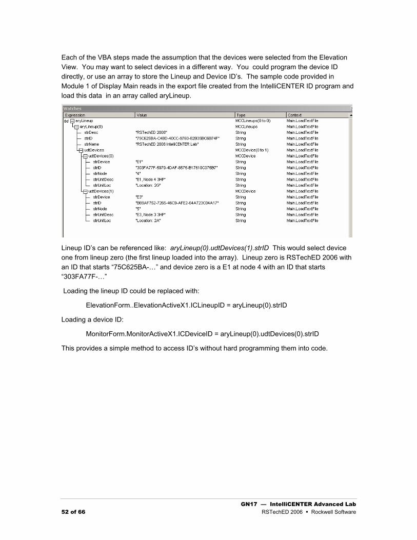
Each of the VBA steps made the assumption that the devices were selected from the Elevation View. You may want to select devices in a different way. You could program the device ID directly, or use an array to store the Lineup and Device ID’s. The sample code provided in Module 1 of Display Main reads in the export file created from the IntelliCENTER ID program and load this data in an array called aryLineup.
Lineup ID’s can be referenced like: aryLineup(0).udtDevices(1).strID This would select device one from lineup zero (the first lineup loaded into the array). Lineup zero is RSTechED 2006 with an ID that starts “75C625BA-…” and device zero is a E1 at node 4 with an ID that starts “303FA77F-…”
Loading the lineup ID could be replaced with:
ElevationForm..ElevationActiveX1.ICLineupID = aryLineup(0).strID
Loading a device ID:
MonitorForm.MonitorActiveX1.ICDeviceID = aryLineup(0).udtDevices(0).strID
This provides a simple method to access ID’s without hard programming them into code.

GN17 — IntelliCENTER Advanced Lab RSTechED 2006 Rockwell Software 53 of 66
Congratulations! You have finished the Advanced IntelliCENTER Lab exercises. We hope you have learned something in this lab and that you have seen the power and flexibility of the IntelliCENTER ActiveX objects.
If you have any suggestions on improvements, please use the last page of this booklet to write them down. Hand the sheet to any of the instructors.

GN17 — IntelliCENTER Advanced Lab 54 of 66 RSTechED 2006 Rockwell Software
Appendix One – Object Model
IntelliCenter Elevation View ActiveX Control
Provides a means of showing the System view to monitor the status of a line up.
Remarks
The Elevation View control’s properties can be set through the control’s property page or through programmable methods. The control will automatically show itself if all its’ properties are set when going into a run time environment. The control’s Show method can be called after the control has entered a run time environment and had changes made to its’ properties. If the user decides to set properties after run time has been established the Show method must be called to refresh the control.
Properties
ICCaption Property
Returns a String containing the object’s name and the object’s line up name.
Syntax
object.ICCaption
Remarks
The ICCaption property is read only and can only be called during runtime.
ICCurrentDeviceID Property
Returns a String containing the ID of the currently selected device.
Syntax
object.ICCurrentDeviceID
Remarks
The ICCurrentDeviceID property is read only and can only be called during runtime.

GN17 — IntelliCENTER Advanced Lab RSTechED 2006 Rockwell Software 55 of 66
ICLanguage
Returns or sets a string that contains the language to be used on the object.
Syntax
object.ICLanguage [= string]
Remarks
You can set the ICLanguage property using the objects property page or you can set it manually. The value must match one of the valid language strings in the IntelliCenter database. The values in the database are; “english”, “spanish”, “french” and “portuguese”. The default value of the property is “english”.
ICLineupID
Returns or sets a String containing the ID for the line up.
Syntax
object.ICLineupID [= string]
Remarks
When setting the ICLineup property you should use an object’s property page or the IntelliCenterID program.
ICLineupName Property
Returns a String containing the name of the object’s line up.
Syntax
object.ICLineupName
Remarks
This property is read only and can only be called during runtime.
Methods
ICMaximize Method
Changes the size of the object to a maximized size inside the container object.
Syntax
object.ICMaximize
Remarks
The object’s height and width are set to a maximized size on the container with this method. The object must be placed at position 0,0 [left, top] on the container for the object to be displayed properly.

GN17 — IntelliCENTER Advanced Lab 56 of 66 RSTechED 2006 Rockwell Software
Show Method
Shows
Syntax
object.Show ()
Remarks
This method must be called after making any changes to the properties. Calling Show will cause the object to reload using the new property values.
Events
LoadComplete Event
This event is raised when the object has completed all initialization for display and communications.
Remarks
This event signals that the object has completed loading and communicating to the device. At this time, properties such as ICCaption can be set.
IntelliCenter Monitor ActiveX Control
Provides a means of monitoring a device in a lineup.
Remarks
The Monitor control’s properties can be set through the control’s property page or through programmable methods. The control will automatically show itself if all its’ properties are set when going into a run time environment. The control’s Show method can be called after the control has entered a run time environment and had changes made to its’ properties. If the user decides to set properties after run time has been established the Show method must be called to refresh the control. The parameters for the device can be edited by using the right click menu.
Properties
ICCaption Property
Returns a String containing the object’s name and the object’s line up name.
Syntax
object.ICCaption
Remarks
The ICCaption property is read only and can only be called during runtime.

GN17 — IntelliCENTER Advanced Lab RSTechED 2006 Rockwell Software 57 of 66
ICDevice Property
Returns a String containing the name of the MCC unit of the object.
Syntax
object.ICDevice
Remarks
This property is read only and can only be called during runtime.
ICDeviceID Property
Returns or sets a String containing the GUID for the device.
Syntax
object.ICDeviceID [= string]
Remarks
When setting the ICDevice property you should use an object’s property page or the IntelliCenterID identifier utility.
ICLanguage
Returns or sets a string that contains the language to be used on the object.
Syntax
object.ICLanguage [= string]
Remarks
You can set the ICLanguage property using the objects property page or you can set it manually. The value must match one of the valid language strings in the IntelliCenter database. The values in the database are; “english”, “spanish”, “french” and “portuguese”. The default value of the property is “english”.
ICLineupID
Returns or sets a String containing the ID for the line up.
Syntax
object.ICLineupID [= string]
Remarks
When setting the ICLineup property you should use an object’s property page or the IntelliCenterID program.
ICLineupName Property
Returns a String containing the name of the object’s line up.

GN17 — IntelliCENTER Advanced Lab 58 of 66 RSTechED 2006 Rockwell Software
Syntax
object.ICLineupName
Remarks
This property is read only and can only be called during runtime.
Methods
Show Method
Shows
Syntax
object.Show ()
Remarks
This method must be called after making any changes to the properties. Calling Show will cause the object to reload using the new property values.
Events
LoadComplete Event
This event is raised when the object has completed all initialization for display and communications.
Remarks
This event signals that the object has completed loading and communicating to the device. At this time, properties such as ICCaption can be set.
IntelliCenter Document ActiveX Control
Provides the ability to view drawings, manuals, spare parts and events for a specific line up or device.
Remarks
The Document control’s properties can be set through the control’s property page or through programmable methods. The control will automatically show itself if all its’ properties are set when going into a run time environment. The control’s Show method can be called after the control has entered a run time environment and had changes made to its’ properties. If the user decides to set properties after run time has been established the Show method must be called to refresh the control.

GN17 — IntelliCENTER Advanced Lab RSTechED 2006 Rockwell Software 59 of 66
Properties
ICCaption Property
Returns a String containing the object’s name and the object’s line up name.
Syntax
object.ICCaption
Remarks
The ICCaption property is read only and can only be called during runtime.
ICDevice Property
Returns a String containing the name of the MCC unit of the object.
Syntax
object.ICDevice
Remarks
This property is read only and can only be called during runtime.
ICDeviceID Property
Returns or sets a String containing the GUID for the device.
Syntax
object.ICDeviceID [= string]
Remarks
When setting the ICDevice property you should use an object’s property page or the IntelliCenterID identifier utility. See ICSingleDevice property.
ICDisplayType Property
Returns or sets a string value that contains the display type of the object.
Syntax
object.ICDisplayType [= string] string The value for the display type.
Display Type Description
cad Display for drawings.
event Display for the event log.
manual Display for device manuals.
spares Display for spare parts.
Remarks

GN17 — IntelliCENTER Advanced Lab 60 of 66 RSTechED 2006 Rockwell Software
The display types are case sensitive and can be set using the object’s property page or manually.
ICLanguage
Returns or sets a string that contains the language to be used on the object.
Syntax
object.ICLanguage [= string]
Remarks
You can set the ICLanguage property using the objects property page or you can set it manually. The value must match one of the valid language strings in the IntelliCenter database. The values in the database are; “english”, “spanish”, “french” and “portuguese”. The default value of the property is “english”.
ICLineupID
Returns or sets a String containing the ID for the line up.
Syntax
object.ICLineupID [= string]
Remarks
When setting the ICLineup property you should use an object’s property page or the IntelliCenterID program.
ICLineupName Property
Returns a String containing the name of the object’s line up.
Syntax
object.ICLineupName
Remarks
This property is read only and can only be called during runtime.
ICSingleDevice Property
Returns or sets a Boolean value that contains the value determining if the object is associated with a single device or the entire line up.
Syntax
object.ICSingleDevice[= boolean]
Remarks
The default value for the ICSingleDevice property is False. If false, all devices will be displayed. If true, ICDeviceID must be set any only that device will be displayed.

GN17 — IntelliCENTER Advanced Lab RSTechED 2006 Rockwell Software 61 of 66
Methods
ICMaximize Method
Changes the size of the object to a maximized size inside the container object.
Syntax
object.ICMaximize
Remarks
The object’s height and width are set to a maximized size on the container with this method. The object must be placed at position 0,0 [left, top] on the container for the object to be displayed properly.
Show Method
Shows
Syntax
object.Show ()
Remarks
This method must be called after making any changes to the properties. Calling Show will cause the object to reload using the new property values.
Events
LoadComplete Event
This event is raised when the object has completed all initialization for display and communications.
Remarks
This event signals that the object has completed loading and communicating to the device. At this time, properties such as ICCaption can be set.
IntelliCenter Spreadsheet ActiveX Control
Provides a way to view a single device or an entire line up. Couldn’t come up with much here.
Remarks
The Spreadsheet control’s properties can be set through the control’s property page or through programmable methods. The control will automatically show itself if all its’ properties are set when going into a run time environment. The control’s Show method can be called after the control has entered a run time environment and had changes made to its’ properties. If the user decides to

GN17 — IntelliCENTER Advanced Lab 62 of 66 RSTechED 2006 Rockwell Software
set properties after run time has been established the Show method must be called to refresh the control. The control is read only. No Editing.
Properties
ICCaption Property
Returns a String containing the object’s name and the object’s line up name.
Syntax
object.ICCaption
Remarks
The ICCaption property is read only and can only be called during runtime.
ICDevice Property
Returns a String containing the name of the MCC unit of the object.
Syntax
object.ICDevice
Remarks
This property is read only and can only be called during runtime.
ICDeviceID Property
Returns or sets a String containing the GUID for the device.
Syntax
object.ICDeviceID [= string]
Remarks
When setting the ICDevice property you should use an object’s property page or the IntelliCenterID identifier utility. See ICSingleDevice property.
ICLanguage
Returns or sets a string that contains the language to be used on the object.
Syntax
object.ICLanguage [= string]
Remarks
You can set the ICLanguage property using the objects property page or you can set it manually. The value must match one of the valid language strings in the IntelliCenter database. The values in the database are; “english”, “spanish”, “french” and “portuguese”. The default value of the property is “english”.

GN17 — IntelliCENTER Advanced Lab RSTechED 2006 Rockwell Software 63 of 66
ICLineupID
Returns or sets a String containing the ID for the line up.
Syntax
object.ICLineupID [= string]
Remarks
When setting the ICLineup property you should use an object’s property page or the IntelliCenterID program.
ICLineupName Property
Returns a String containing the name of the object’s line up.
Syntax
object.ICLineupName
Remarks
This property is read only and can only be called during runtime.
ICSingleDevice Property
Returns or sets a Boolean value that contains the value determining if the object is associated with a single device or the entire line up.
Syntax
object.ICSingleDevice[= boolean]
Remarks
The default value for the ICSingleDevice property is False. If false, all devices will be displayed. If true, ICDeviceID must be set any only that device will be displayed.

GN17 — IntelliCENTER Advanced Lab 64 of 66 RSTechED 2006 Rockwell Software
Methods
ICMaximize Method
Changes the size of the object to a maximized size inside the container object.
Syntax
object.ICMaximize
Remarks
The object’s height and width are set to a maximized size on the container with this method. The object must be placed at position 0,0 [left, top] on the container for the object to be displayed properly.
Show Method
Shows
Syntax
object.Show ()
Remarks
This method must be called after making any changes to the properties. Calling Show will cause the object to reload using the new property values.
Events
LoadComplete Event
This event is raised when the object has completed all initialization for display and communications.
Remarks
This event signals that the object has completed loading and communicating to the device. At this time, properties such as ICCaption can be set.

GN17 — IntelliCENTER Advanced Lab RSTechED 2006 Rockwell Software 65 of 66
Ideas for Improving IntelliCENTER
Please use the area below to let us know any ideas that you have. Thank you in advance for your time.

GN17 — IntelliCENTER Advanced Lab 66 of 66 RSTechED 2006 Rockwell Software
Notes