global presence. local expertise. · accumulator technology 30.000 global presence. local...
TRANSCRIPT
Ele
ctro
nics
180
.000
Acc
esso
ries
61.0
00C
ompa
ct H
ydra
ulic
s 53
.000
Filte
r Sys
tem
s 79
.000
Pro
cess
Tec
hnol
ogy
77.0
00Fi
lter T
echn
olog
y 70
.000
Acc
umul
ator
Tec
hnol
ogy
30.0
00
Global Presence.Local Expertise.www.hydac.com
Industriegebiet 66280 Sulzbach/Saar Germany
Tel.: +49 (0)6897 509-01 Fax: +49 (0)6897 509-300
E-Mail: fi [email protected]
HYDAC FILTERTECHNIK GMBH
HYDAC Head Offi ce
HYDAC Companies
HYDAC Sales and Service Partners
Coo
ling
Sys
tem
s 5.
700
E 1
0.77
7.0/
01.1
3
E 1
0.77
7.0/
01.1
3
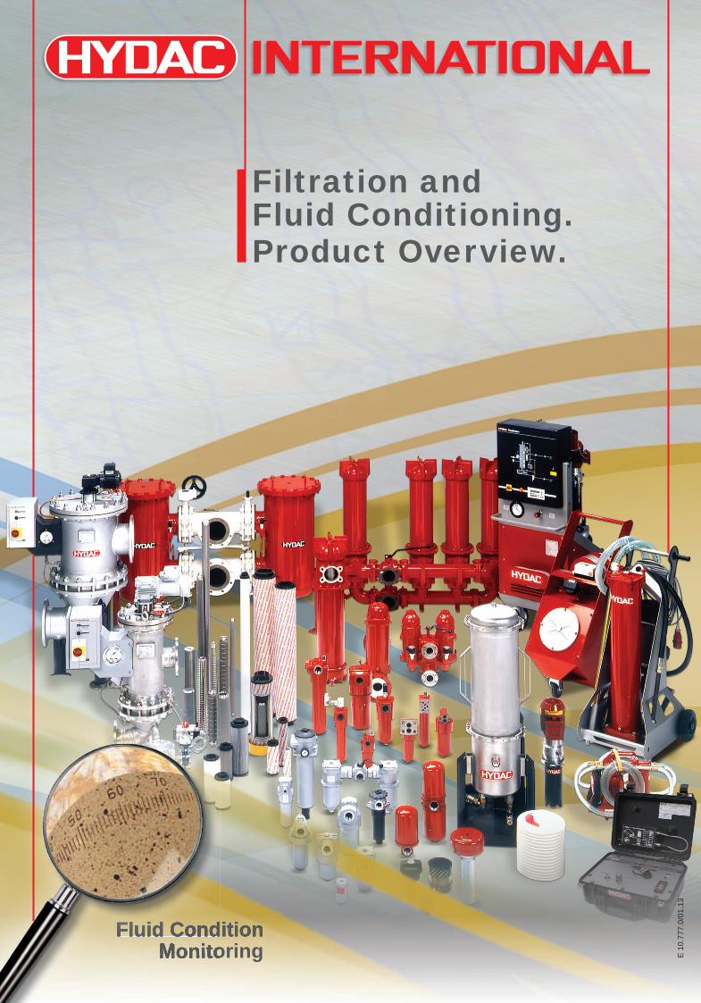
Filtration andFluid Conditioning.Product Overview.
Industriegebiet 66280 Sulzbach/Saar Germany
Tel.: +49 (0)6897 509-01 Fax: +49 (0)6897 509-846
E-Mail: fi [email protected]
Industriegebiet Grube König Am Wrangelfl öz 1 66538 Neunkirchen Germany
Tel.: +49 (0)6897 509-1241 Fax: +49 (0)6897 509-1278
E-Mail: [email protected]
HYDAC FILTER SYSTEMS GMBH
HYDAC PROCESS TECHNOLOGY GMBH
Internet: www.hydac.com
Fluid Condition Monitoring
Fluid Condition Monitoring
Fluid Condition Monitoring
Fluid Condition Monitoring
e_HYDAC_Gesamtfilterübersicht_Umschlag_EL_101212.indd 1-3 15.01.13 15:09:37

E 10
.777
.0/0
1.13
2
E 10
.777
.0/0
1.13
3
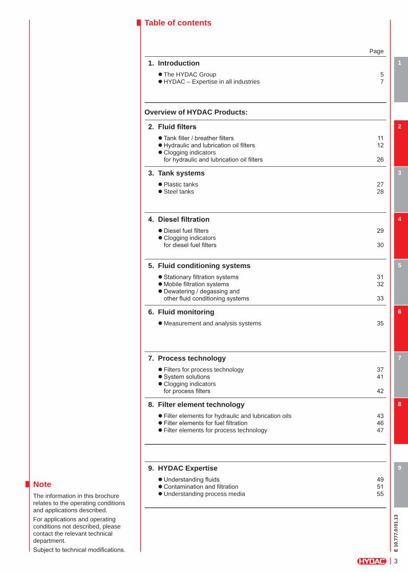
Table of contents
NoteThe information in this brochure relates to the operating conditions and applications described.For applications and operating conditions not described, please contact the relevant technical department.Subject to technical modifications.
Page
1. Introduction z The HYDAC Group 5 zHYDAC – Expertise in all industries 7
1
Overview of HYDAC Products:
2. Fluidfilters z Tank filler / breather filters 11 zHydraulic and lubrication oil filters 12 zClogging indicators for hydraulic and lubrication oil filters 26
2
3. Tank systems zPlastic tanks 27 zSteel tanks 28
3
4. Dieselfiltration zDiesel fuel filters 29 zClogging indicators for diesel fuel filters 30
4
5. Fluid conditioning systems zStationary filtration systems 31 zMobile filtration systems 32 zDewatering / degassing and other fluid conditioning systems 33
5
6. Fluid monitoring zMeasurement and analysis systems 35
6
7. Process technology z Filters for process technology 37 zSystem solutions 41 zClogging indicators for process filters 42
7
8. Filter element technology z Filter elements for hydraulic and lubrication oils 43 z Filter elements for fuel filtration 46 z Filter elements for process technology 47
8
9. HYDAC Expertise zUnderstanding fluids 49 zContamination and filtration 51 zUnderstanding process media 55
9

E 10
.777
.0/0
1.13
4
E 10
.777
.0/0
1.13
5
HYDAC FluidCareCenter Sulzbach/Saar
1
Components SystemsFluid Engineeringand Service
The HYDAC Group
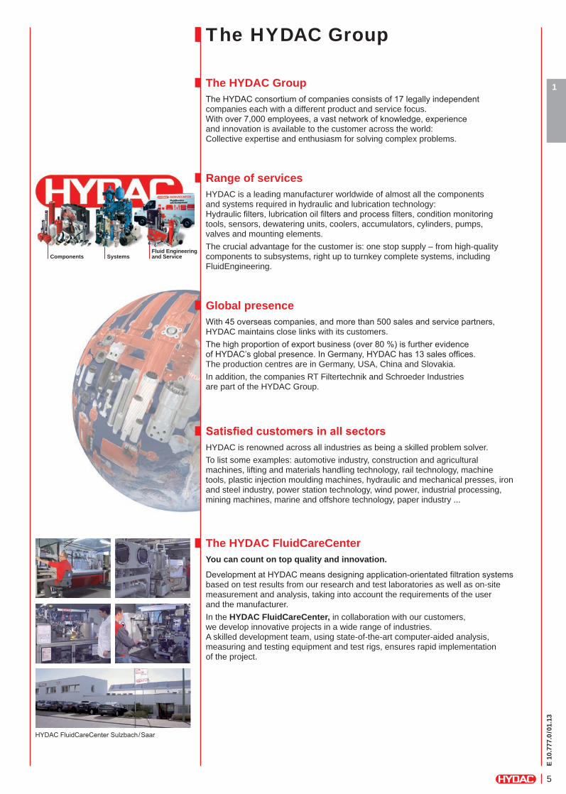
The HYDAC GroupThe HYDAC consortium of companies consists of 17 legally independent companies each with a different product and service focus. With over 7,000 employees, a vast network of knowledge, experience and innovation is available to the customer across the world:Collective expertise and enthusiasm for solving complex problems.
Range of servicesHYDAC is a leading manufacturer worldwide of almost all the components and systems required in hydraulic and lubrication technology:Hydraulic fi lters, lubrication oil fi lters and process fi lters, condition monitoring tools, sensors, dewatering units, coolers, accumulators, cylinders, pumps, valves and mounting elements.The crucial advantage for the customer is: one stop supply – from high-quality components to subsystems, right up to turnkey complete systems, including FluidEngineering.
Global presenceWith 45 overseas companies, and more than 500 sales and service partners, HYDAC maintains close links with its customers. The high proportion of export business (over 80 %) is further evidence of HYDAC’s global presence. In Germany, HYDAC has 13 sales offi ces. The production centres are in Germany, USA, China and Slovakia.In addition, the companies RT Filtertechnik and Schroeder Industries are part of the HYDAC Group.
SatisfiedcustomersinallsectorsHYDAC is renowned across all industries as being a skilled problem solver.To list some examples: automotive industry, construction and agricultural machines, lifting and materials handling technology, rail technology, machine tools, plastic injection moulding machines, hydraulic and mechanical presses, iron and steel industry, power station technology, wind power, industrial processing, mining machines, marine and offshore technology, paper industry ...
The HYDAC FluidCareCenterYou can count on top quality and innovation.
Development at HYDAC means designing application-orientated fi ltration systems based on test results from our research and test laboratories as well as on-site measurement and analysis, taking into account the requirements of the user and the manufacturer.In the HYDAC FluidCareCenter, in collaboration with our customers, we develop innovative projects in a wide range of industries. A skilled development team, using state-of-the-art computer-aided analysis, measuring and testing equipment and test rigs, ensures rapid implementation of the project.
E 10
.777
.0/0
1.13
6
HYDAC fi lter systems andcondition monitoring equipment
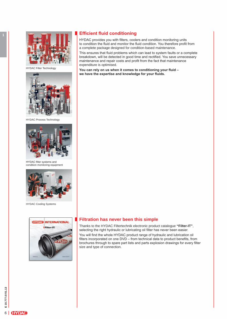
1 EfficientfluidconditioningHYDAC provides you with fi lters, coolers and condition monitoring units to condition the fl uid and monitor the fl uid condition. You therefore profi t from a complete package designed for condition-based maintenance.This ensures that fl uid problems which can lead to system faults or a complete breakdown, will be detected in good time and rectifi ed. You save unnecessary maintenance and repair costs and profi t from the fact that maintenance expenditure is optimised.Youcanrelyonuswhenitcomestoconditioningyourfluid–wehavetheexpertiseandknowledgeforyourfluids.
Filtration has never been this simpleThanks to the HYDAC Filtertechnik electronic product catalogue “Filter-IT”,selecting the right hydraulic or lubricating oil fi lter has never been easier. You will fi nd the whole HYDAC product range of hydraulic and lubrication oil fi lters incorporated on one DVD – from technical data to product benefi ts, from brochures through to spare part lists and parts explosion drawings for every fi lter size and type of connection.
HYDAC Cooling Systems
HYDAC Filter Technology
HYDAC Process Technology

E 10
.777
.0/0
1.13
7
1
Overview of Industries and ApplicationsWithus,yourfluidisinsafehands.The specialists at HYDAC have a good knowledge of your fl uid and welcome the opportunity to help you reduce the burden of fl uid conditioning. You will see for yourself the clear benefi t of having a system that works perfectly, leaving you to concentrate fully on your area of expertise. When you decide on a HYDAC product, you are also benefi tting at the same time from the HYDAC network of expertise and service available worldwide:
Highest level of operating reliability for your applicationsIn HYDAC you have a professional partner for all aspects of fl uid cleanliness as well as operating reliability and availability for your system or machine.The HYDAC fi lter range is also impressive with over 50 types of fi lter in every conceivable size and type. In addition, new individual solutions are constantly being developed, partly in active development partnership with the manufacturers.
FiltrationandfluidconditioningwithHYDACprovides you with the following advantages:Low costsIndustry-optimised fi lter elements and housings
Easy to serviceSimple element change and easy-to-install fi lter housing
High level of operating reliabilityFilter media have high fi ltration effi ciency for exceptional cleanliness classes and benefi t from a high level of production quality
Low operating costsParticularly low pressure drops across fi lter and fi lter elementfor low energy consumption
All components and systems from one supplierProviding comprehensive system know-how and an integrated system approach
Worldwide availability and adviceProvided by our worldwide network of regional offi ces, agents and service partners
HYDAC Quality
All from a single source
Local expertise
Global presence
Systemexpertise
Professionalfluidmanagement
Servicespecialists
Q
E 10
.777
.0/0
1.13
8
1
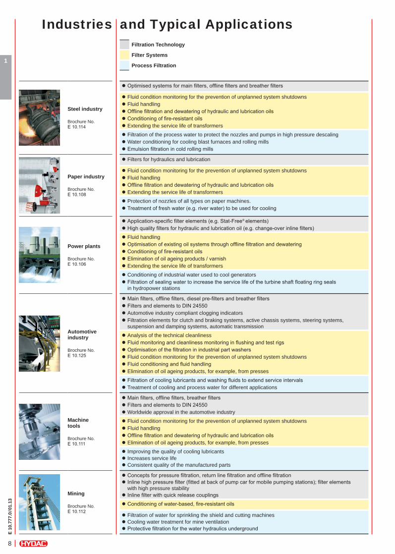
Industries and Typical Applications
Steel industry Brochure No. E 10.114
z Optimised systems for main filters, offline filters and breather filters
z Fluid condition monitoring for the prevention of unplanned system shutdowns z Fluid handling z Offline filtration and dewatering of hydraulic and lubrication oils z Conditioning of fire-resistant oils z Extending the service life of transformers
z Filtration of the process water to protect the nozzles and pumps in high pressure descaling z Water conditioning for cooling blast furnaces and rolling mills z Emulsion filtration in cold rolling mills
Paper industry Brochure No. E 10.108
z Filters for hydraulics and lubrication
z Fluid condition monitoring for the prevention of unplanned system shutdowns z Fluid handling z Offline filtration and dewatering of hydraulic and lubrication oils z Extending the service life of transformers
z Protection of nozzles of all types on paper machines. z Treatment of fresh water (e.g. river water) to be used for cooling
Power plants Brochure No. E 10.106
z Application-specific filter elements (e.g. Stat-Free® elements) z High quality filters for hydraulic and lubrication oil (e.g. change-over inline filters)
z Fluid handling z Optimisation of existing oil systems through offline filtration and dewatering z Conditioning of fire-resistant oils z Elimination of oil ageing products / varnish z Extending the service life of transformers
z Conditioning of industrial water used to cool generators z Filtration of sealing water to increase the service life of the turbine shaft floating ring seals in hydropower stations
Automotive industry Brochure No. E 10.125
z Main filters, offline filters, diesel pre-filters and breather filters z Filters and elements to DIN 24550 z Automotive industry compliant clogging indicators z Filtration elements for clutch and braking systems, active chassis systems, steering systems, suspension and damping systems, automatic transmission
z Analysis of the technical cleanliness z Fluid monitoring and cleanliness monitoring in flushing and test rigs z Optimisation of the filtration in industrial part washers z Fluid condition monitoring for the prevention of unplanned system shutdowns z Fluid conditioning and fluid handling z Elimination of oil ageing products, for example, from presses
z Filtration of cooling lubricants and washing fluids to extend service intervals z Treatment of cooling and process water for different applications
Machine tools Brochure No. E 10.111
z Main filters, offline filters, breather filters z Filters and elements to DIN 24550 z Worldwide approval in the automotive industry
z Fluid condition monitoring for the prevention of unplanned system shutdowns z Fluid handling z Offline filtration and dewatering of hydraulic and lubrication oils z Elimination of oil ageing products, for example, from presses
z Improving the quality of cooling lubricants z Increases service life z Consistent quality of the manufactured parts
Mining Brochure No. E 10.112
z Concepts for pressure filtration, return line filtration and offline filtration z Inline high pressure filter (fitted at back of pump car for mobile pumping stations); filter elements with high pressure stability
z Inline filter with quick release couplings
z Conditioning of water-based, fire-resistant oils
z Filtration of water for sprinkling the shield and cutting machines z Cooling water treatment for mine ventilation z Protective filtration for the water hydraulics underground
Filtration Technology
Filter Systems
Process Filtration
E 10
.777
.0/0
1.13
9
1
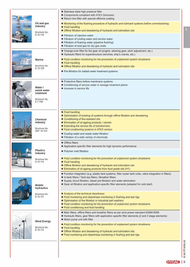
Oil and gas industry Brochure No. E 10.118
z Stainless steel high pressure filter z Components compliant with ATEX Directives z Return line filter with special offshore coating
z Monitoring of the flushing procedure of hydraulic and lubricant systems before commissioning z Fluid handling z Offline filtration and dewatering of hydraulic and lubrication oils
z Filtration of injection water z Filtration of cooling water and service water z Filtration of flushing water (pipeline flushing) z Filtration of seal gas for dry gas seals
Marine Brochure No. E 10.129
z Change-over filter for the gear oil (engine, steering gear, pitch adjustment, etc.) z Hydraulic filters for superstructure (winches, ship’s cranes, etc.)
z Fluid condition monitoring for the prevention of unplanned system shutdowns z Fluid handling z Offline filtration and dewatering of hydraulic and lubrication oils
z Pre-filtration for ballast water treatment systems
Water / waste water treatment Brochure No. E 7.709
z Protective filters before membrane systems z Conditioning of service water in sewage treatment plants z Increase in service life
Chemical industry Brochure No. DEF 10.103
z Fluid handling z Optimisation of existing oil systems through offline filtration and dewatering z Conditioning of fire-resistant oils z Elimination of oil ageing products / varnish z Extending the service life of transformers z Fluid conditioning systems in ATEX version
z Cooling water and waste water filtration z Filtration of a wide variety of chemicals
Plastics industry Brochure No. E 10.115
z Offline filters z Application-specific filter elements for high dynamic performance
z Polymer melt filtration
z Fluid condition monitoring for the prevention of unplanned system shutdowns z Fluid handling z Offline filtration and dewatering of hydraulic and lubrication oils z Elimination of oil ageing products from food grade oils (H1)
Mobile hydraulics Brochure No. E 10.121
z Function integration (e.g. plastic tank systems, filter cooler tank units, valve integration in filters) z In-tank filters / Tank-top filters / Breather filters z Supply circuit filtration, diesel pre-filtration and water elimination z Gear oil filtration and application-specific filter elements (adapted for cold start)
z Analysis of the technical cleanliness z Fluid monitoring and cleanliness monitoring in flushing and test rigs z Optimisation of the filtration in industrial part washers z Fluid condition monitoring for the prevention of unplanned system shutdowns z Fluid conditioning and fluid handling
Wind Energy Brochure No. E 10.113
z Main filters, offline filters and breather filters as per wind power standard AGMA 6006 z Hydraulic filters, gear filters with application specific filter elements (2 and 3 stage elements) z Motor pump unit with filter
z Fluid condition monitoring for the prevention of unplanned system shutdowns z Fluid handling z Offline filtration and dewatering of hydraulic and lubrication oils z Fluid monitoring and cleanliness monitoring in flushing and test rigs

E 10
.777
.0/0
1.13
10
1
E 10
.777
.0/0
1.13
11
1
2
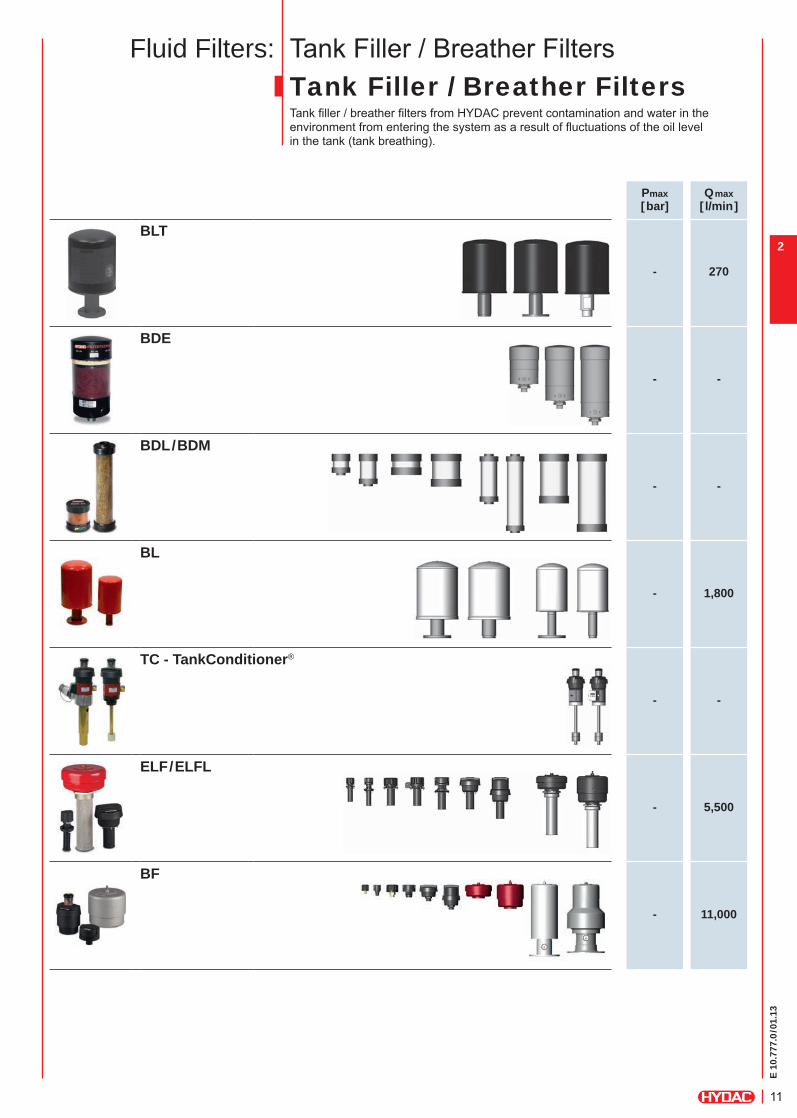
Tank Filler / Breather FiltersTank Filler / Breather FiltersTank fi ller / breather fi lters from HYDAC prevent contamination and water in the environment from entering the system as a result of fl uctuations of the oil level in the tank (tank breathing).
Pmax[bar]
Qmax[ l/min]
BLT
- 270
BDE
- -
BDL/BDM
- -
BL
- 1,800
TC - TankConditioner®
- -
ELF/ELFL
- 5,500
BF
- 11,000
Fluid Filters:
E 10
.777
.0/0
1.13
12
2Pmax[bar]
Qmax[ l/min]
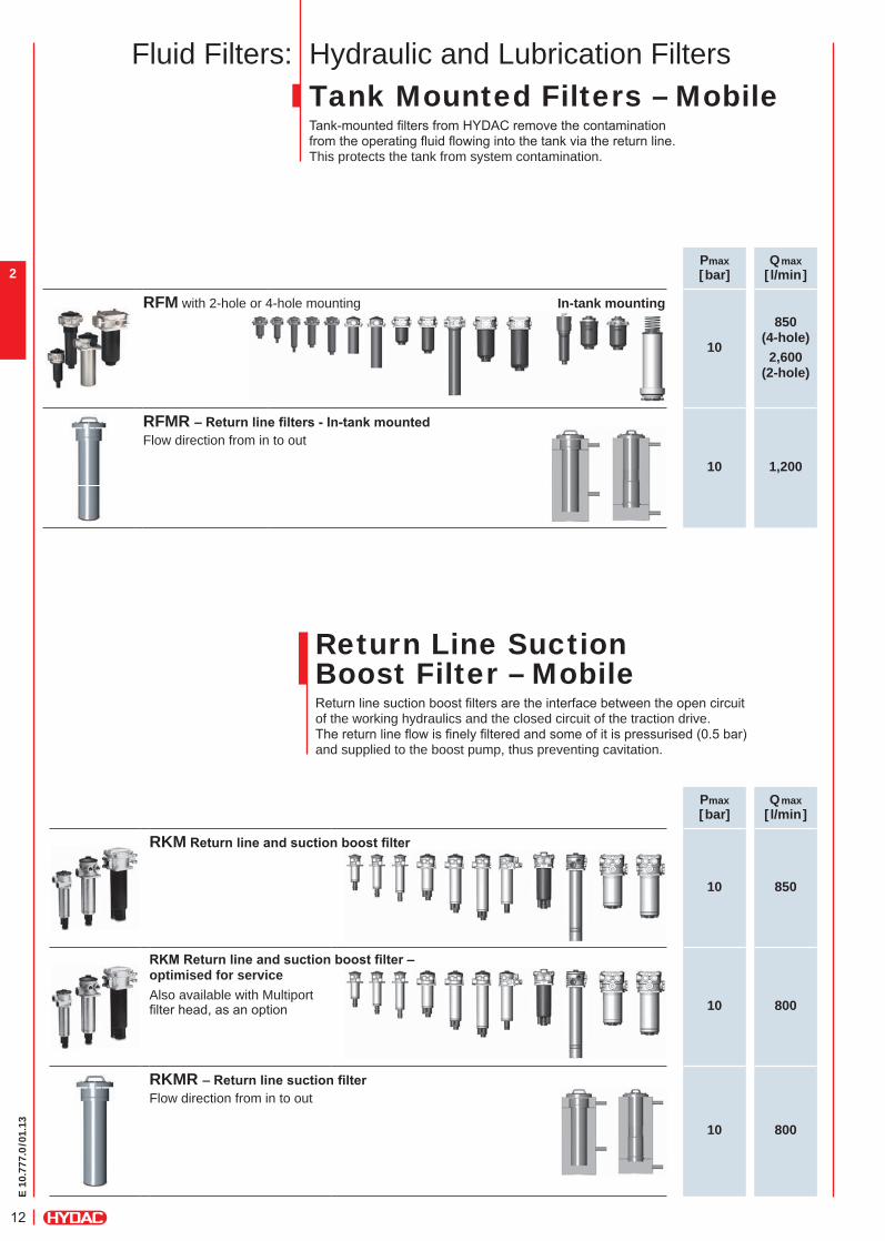
RFM with 2-hole or 4-hole mounting In-tank mounting
10
850(4-hole)2,600
(2-hole)
RFMR –Returnlinefilters-In-tankmounted
10 1,200
Flow direction from in to out
Tank Mounted Filters – MobileTank-mounted fi lters from HYDAC remove the contamination from the operating fl uid fl owing into the tank via the return line. This protects the tank from system contamination.
Return Line Suction Boost Filter – MobileReturn line suction boost fi lters are the interface between the open circuit of the working hydraulics and the closed circuit of the traction drive.The return line fl ow is fi nely fi ltered and some of it is pressurised (0.5 bar) and supplied to the boost pump, thus preventing cavitation.
Hydraulic and Lubrication FiltersFluid Filters:
Pmax[bar]
Qmax[ l/min]
RKM Returnlineandsuctionboostfilter
10 850
RKMReturnlineandsuctionboostfilter–
10 800
optimised for serviceAlso available with Multiportfi lter head, as an option
RKMR –Returnlinesuctionfilter
10 800
Flow direction from in to out
E 10
.777
.0/0
1.13
13
1
2
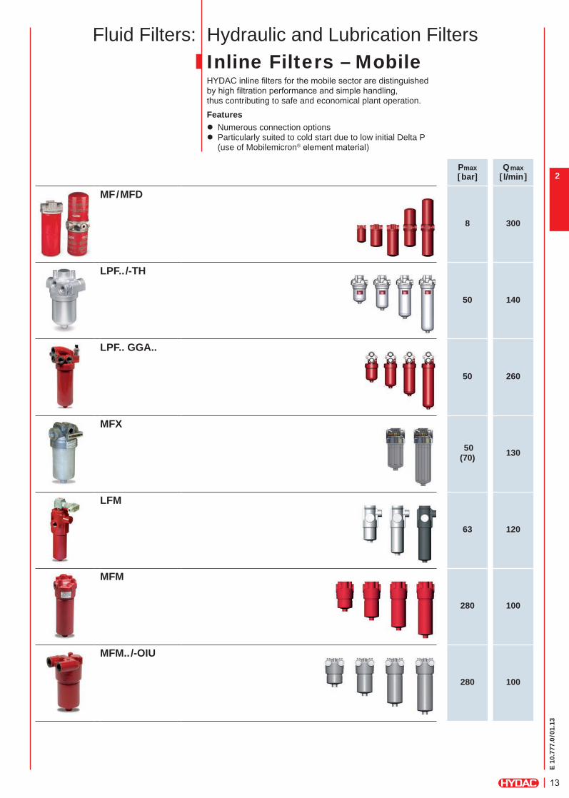
Fluid Filters: Hydraulic and Lubrication FiltersInline Filters – MobileHYDAC inline fi lters for the mobile sector are distinguished by high fi ltration performance and simple handling, thus contributing to safe and economical plant operation.Features
z Numerous connection options z Particularly suited to cold start due to low initial Delta P (use of Mobilemicron® element material)
Pmax[bar]
Qmax[ l/min]
MF/MFD
8 300
LPF.. /-TH
50 140
LPF.. GGA..
50 260
MFX
50(70) 130
LFM
63 120
MFM
280 100
MFM../-OIU
280 100
E 10
.777
.0/0
1.13
14
2Pmax[bar]
Qmax[ l/min]
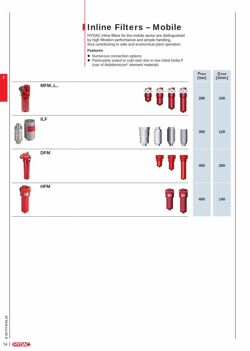
MFM..L..
280 100
ILF
350 120
DFM
400 280
HFM
400 140
Inline Filters – MobileHYDAC inline fi lters for the mobile sector are distinguished by high fi ltration performance and simple handling, thus contributing to safe and economical plant operation.Features
z Numerous connection options z Particularly suited to cold start due to low initial Delta P (use of Mobilemicron® element material)
E 10
.777
.0/0
1.13
15
1
2Pmax[bar]
Qmax[ l/min]
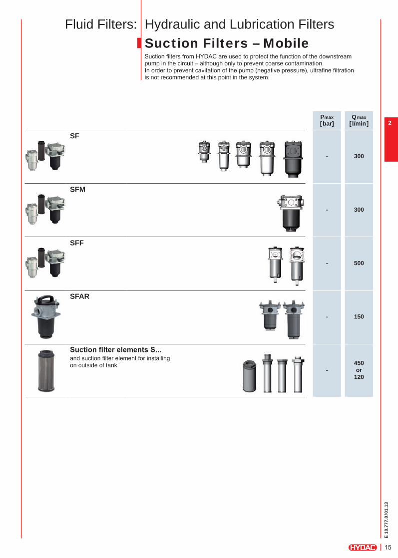
SF
- 300
SFM
- 300
SFF
- 500
SFAR
- 150
SuctionfilterelementsS...
-450 or
120
and suction fi lter element for installing on outside of tank
Hydraulic and Lubrication FiltersSuction Filters – MobileSuction fi lters from HYDAC are used to protect the function of the downstreampump in the circuit – although only to prevent coarse contamination. In order to prevent cavitation of the pump (negative pressure), ultrafi ne fi ltration is not recommended at this point in the system.
Fluid Filters:
E 10
.777
.0/0
1.13
16
2
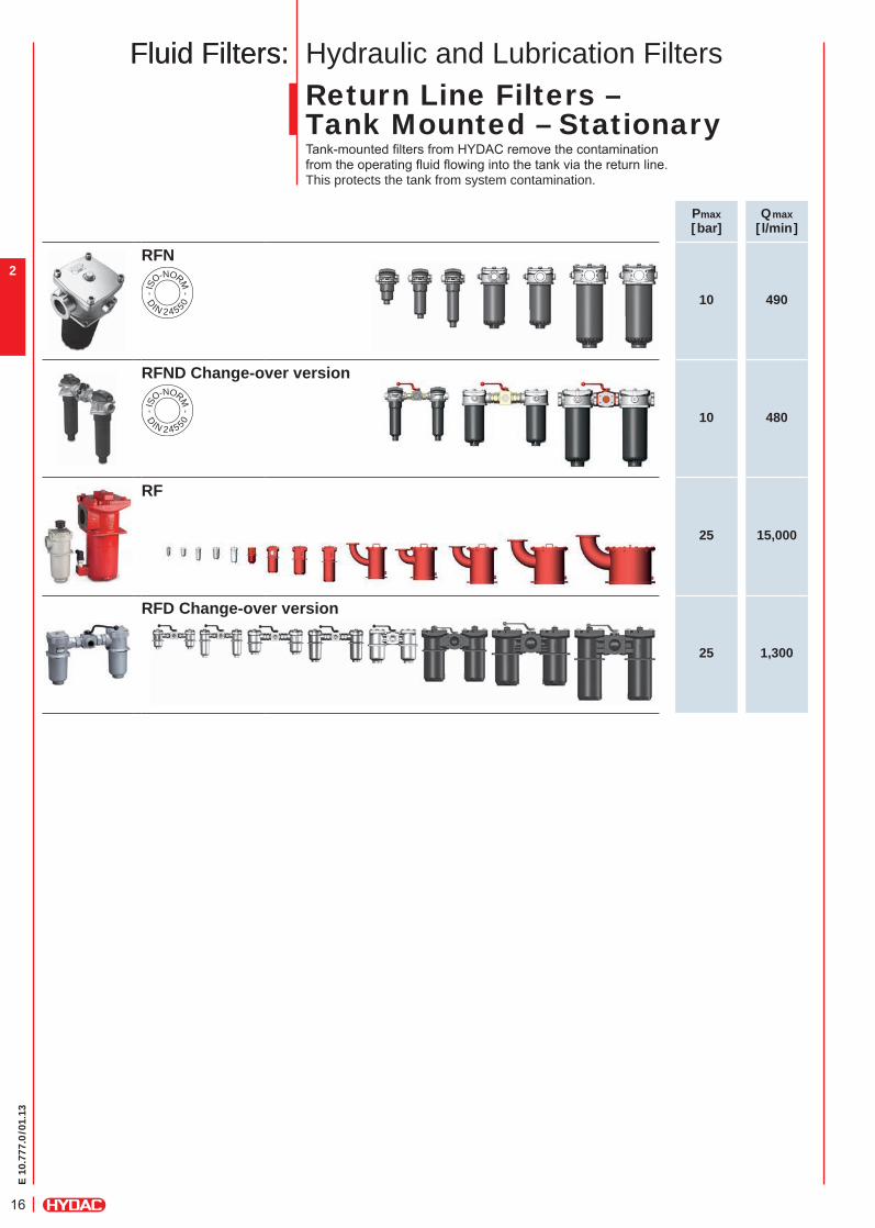
Return Line Filters – Tank Mounted – StationaryTank-mounted fi lters from HYDAC remove the contamination from the operating fl uid fl owing into the tank via the return line.This protects the tank from system contamination.
Hydraulic and Lubrication Filters
Pmax[bar]
Qmax[ l/min]
RFN
10 490 - IS
O-NORM -
D
IN 2455 0
RFND Change-over version
10 480 - IS
O-NORM -
D
IN 2455 0
RF
25 15,000
RFD Change-over version
25 1,300
Fluid Filters:Fluid Filters:
E 10
.777
.0/0
1.13
17
1
2
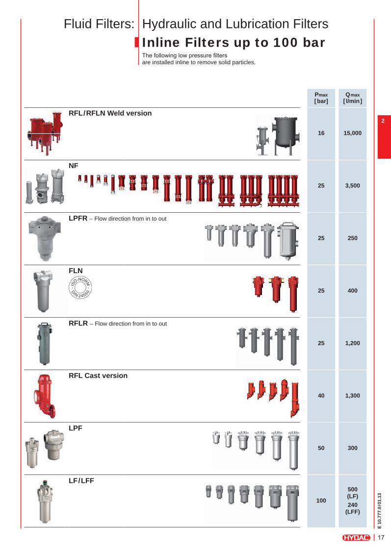
Hydraulic and Lubrication FiltersInline Filters up to 100 barThe following low pressure fi lters are installed inline to remove solid particles.
Pmax[bar]
Qmax[ l/min]
RFL/RFLN Weld version
16 15,000
NF
25 3,500
LPFR – Flow direction from in to out
25 250
FLN
25 400 - IS
O-NORM -
D
IN 2455 0
RFLR – Flow direction from in to out
25 1,200
RFL Cast version
40 1,300
LPF
50 300
LF/LFF
100
500 (LF)240
(LFF)
Fluid Filters:
E 10
.777
.0/0
1.13
18
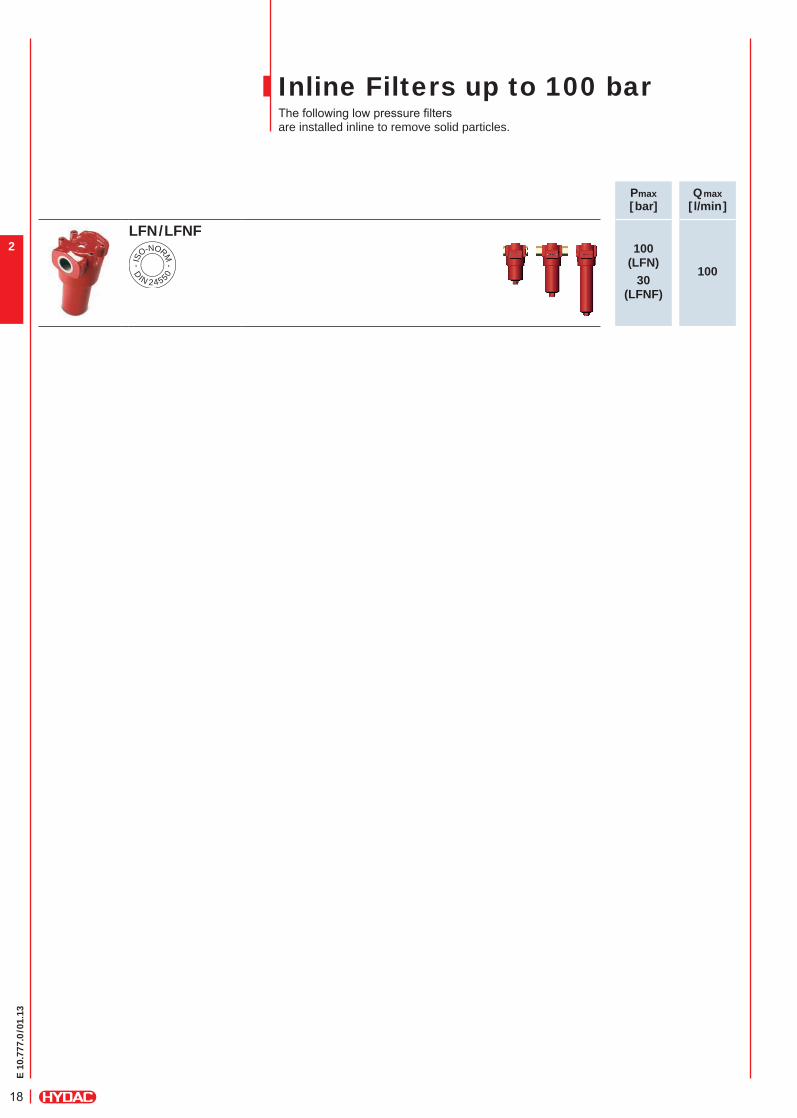
2
Pmax[bar]
Qmax[ l/min]
LFN/LFNF100
(LFN)30
(LFNF)
100 - IS
O-NORM -
D
IN 2455 0
Inline Filters up to 100 barThe following low pressure fi lters are installed inline to remove solid particles.

E 10
.777
.0/0
1.13
19
1
2
Hydraulic and Lubrication FiltersInline Filters from 100 barThe following high pressure fi lters are designed for inline installation.They are distinguished by low pressure losses and high endurance strength.
Pmax[bar]
Qmax[ l/min]
LFR – Flow direction from in to out
120 250
MDFR – Flow direction from in to out
250 250
MDF
280 280
HDF/HDFF
280(420) 380
DFN/DFNF
400 350 - IS
O-NORM -
D
IN 2455 0
DF/DFF
4201,800(DFF:1,000)
DFFX
420 1,000
Fluid Filters:
E 10
.777
.0/0
1.13
20
2
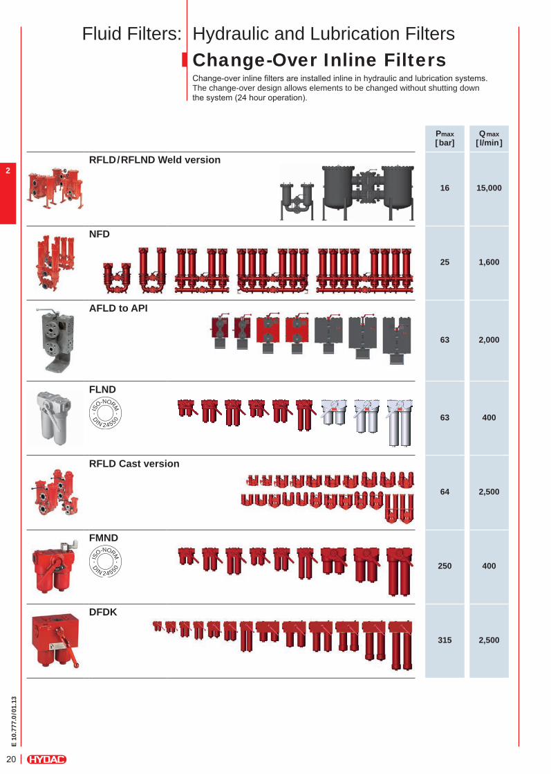
Hydraulic and Lubrication Filters
Pmax[bar]
Qmax[ l/min]
RFLD/RFLND Weld version
16 15,000
NFD
25 1,600
AFLD to API
63 2,000
FLND
63 400 - IS
O-NORM -
D
IN 2455 0
RFLD Cast version
64 2,500
FMND
250 400 - IS
O-NORM -
D
IN 2455 0
DFDK
315 2,500
Change-Over Inline FiltersChange-over inline fi lters are installed inline in hydraulic and lubrication systems. The change-over design allows elements to be changed without shutting down the system (24 hour operation).
Fluid Filters:
E 10
.777
.0/0
1.13
21
1
2
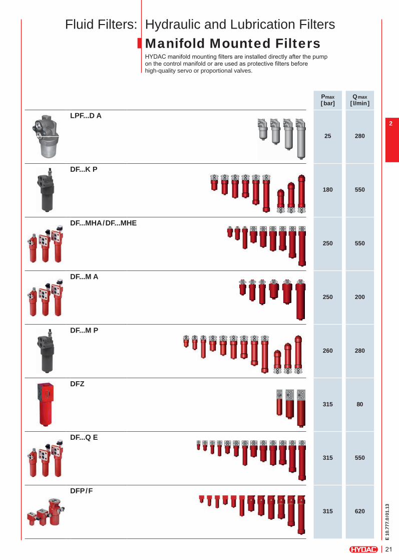
Hydraulic and Lubrication FiltersManifold Mounted FiltersHYDAC manifold mounting fi lters are installed directly after the pump on the control manifold or are used as protective fi lters before high-quality servo or proportional valves.
Pmax[bar]
Qmax[ l/min]
LPF...D A
25 280
DF...K P
180 550
DF...MHA/DF...MHE
250 550
DF...M A
250 200
DF...M P
260 280
DFZ
315 80
DF...Q E
315 550
DFP/F
315 620
Fluid Filters:
E 10
.777
.0/0
1.13
22
2
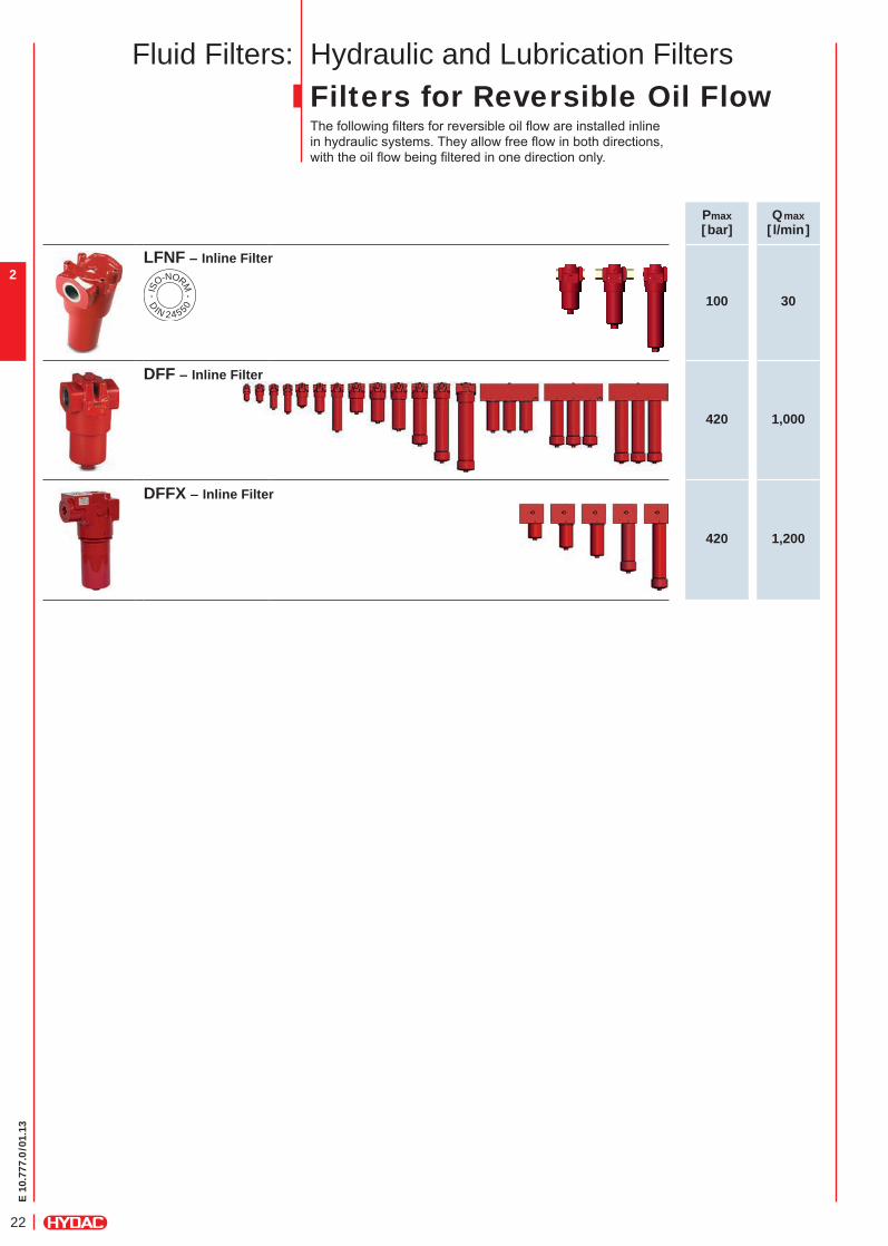
Hydraulic and Lubrication FiltersFilters for Reversible Oil FlowThe following fi lters for reversible oil fl ow are installed inline in hydraulic systems. They allow free fl ow in both directions, with the oil fl ow being fi ltered in one direction only.
Pmax[bar]
Qmax[ l/min]
LFNF – Inline Filter
100 30 - IS
O-NORM -
D
IN 2455 0
DFF – Inline Filter
420 1,000
DFFX – Inline Filter
420 1,200
Fluid Filters:
E 10
.777
.0/0
1.13
23
1
2
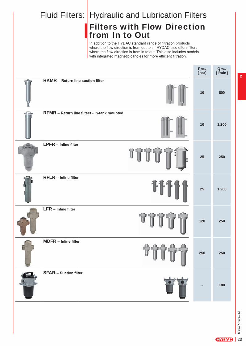
Hydraulic and Lubrication FiltersFilters with Flow Directionfrom In to OutIn addition to the HYDAC standard range of fi ltration products where the fl ow direction is from out to in, HYDAC also offers fi lters where the fl ow direction is from in to out. This also includes models with integrated magnetic candles for more effi cient fi ltration.
Pmax[bar]
Qmax[ l/min]
RKMR – Returnlinesuctionfilter
10 800
RFMR – Returnlinefilters-In-tankmounted
10 1,200
LPFR – Inlinefilter
25 250
RFLR – Inlinefilter
25 1,200
LFR – Inlinefilter
120 250
MDFR – Inlinefilter
250 250
SFAR – Suctionfilter
- 180
Fluid Filters:
E 10
.777
.0/0
1.13
24
2
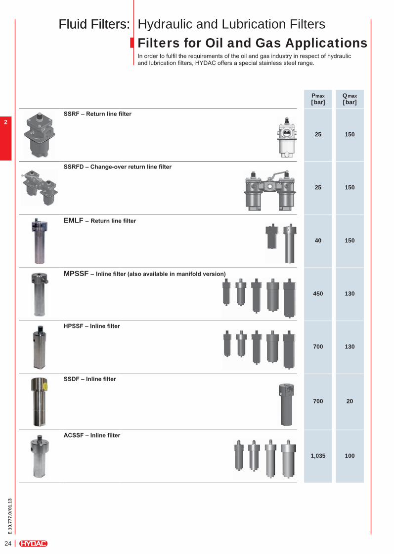
Hydraulic and Lubrication FiltersFilters for Oil and Gas ApplicationsIn order to fulfi l the requirements of the oil and gas industry in respect of hydraulic and lubrication fi lters, HYDAC offers a special stainless steel range.
Pmax[bar]
Qmax[bar]
SSRF–Returnlinefilter
25 150
SSRFD–Change-overreturnlinefilter
25 150
EMLF – Returnlinefilter
40 150
MPSSF – Inlinefilter(alsoavailableinmanifoldversion)
450 130
HPSSF–Inlinefilter
700 130
SSDF–Inlinefilter
700 20
ACSSF–Inlinefilter
1,035 100
Fluid Filters:Fluid Filters:
E 10
.777
.0/0
1.13
25
1
2
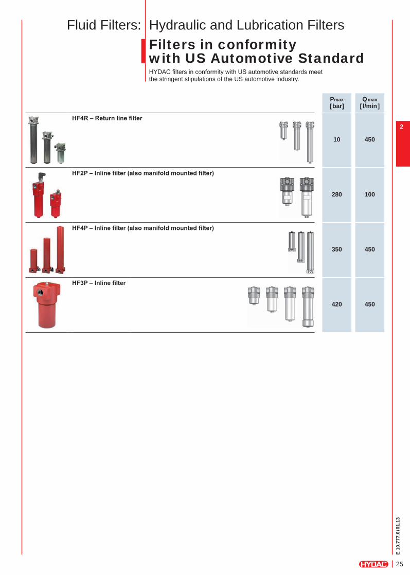
Hydraulic and Lubrication FiltersFilters in conformity with US Automotive StandardHYDAC fi lters in conformity with US automotive standards meet the stringent stipulations of the US automotive industry.
Pmax[bar]
Qmax[ l/min]
HF4R–Returnlinefilter
10 450
HF2P–Inlinefilter(alsomanifoldmountedfilter)
280 100
HF4P–Inlinefilter(alsomanifoldmountedfilter)
350 450
HF3P–Inlinefilter
420 450
Fluid Filters:
E 10
.777
.0/0
1.13
26
2
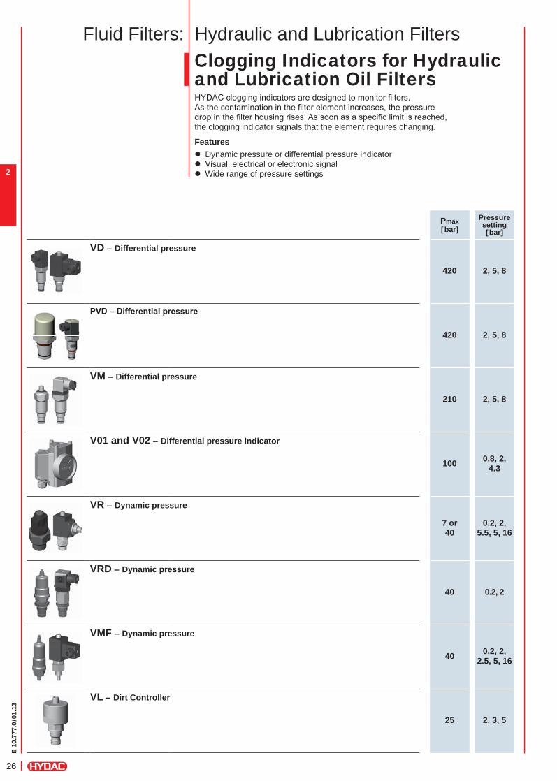
Hydraulic and Lubrication FiltersClogging Indicators for Hydraulic and Lubrication Oil FiltersHYDAC clogging indicators are designed to monitor fi lters.As the contamination in the fi lter element increases, the pressure drop in the fi lter housing rises. As soon as a specifi c limit is reached, the clogging indicator signals that the element requires changing.
Features z Dynamic pressure or differential pressure indicator z Visual, electrical or electronic signal z Wide range of pressure settings
Fluid Filters:
Pmax[bar]
Pressuresetting[bar]
VD – Differential pressure
420 2, 5, 8
PVD–Differentialpressure
420 2, 5, 8
VM – Differential pressure
210 2, 5, 8
V01 and V02 – Differential pressure indicator
100 0.8, 2, 4.3
VR – Dynamic pressure
7 or 40
0.2, 2, 5.5, 5, 16
VRD – Dynamic pressure
40 0.2, 2
VMF – Dynamic pressure
40 0.2, 2, 2.5, 5, 16
VL – Dirt Controller
25 2, 3, 5
E 10
.777
.0/0
1.13
27
3
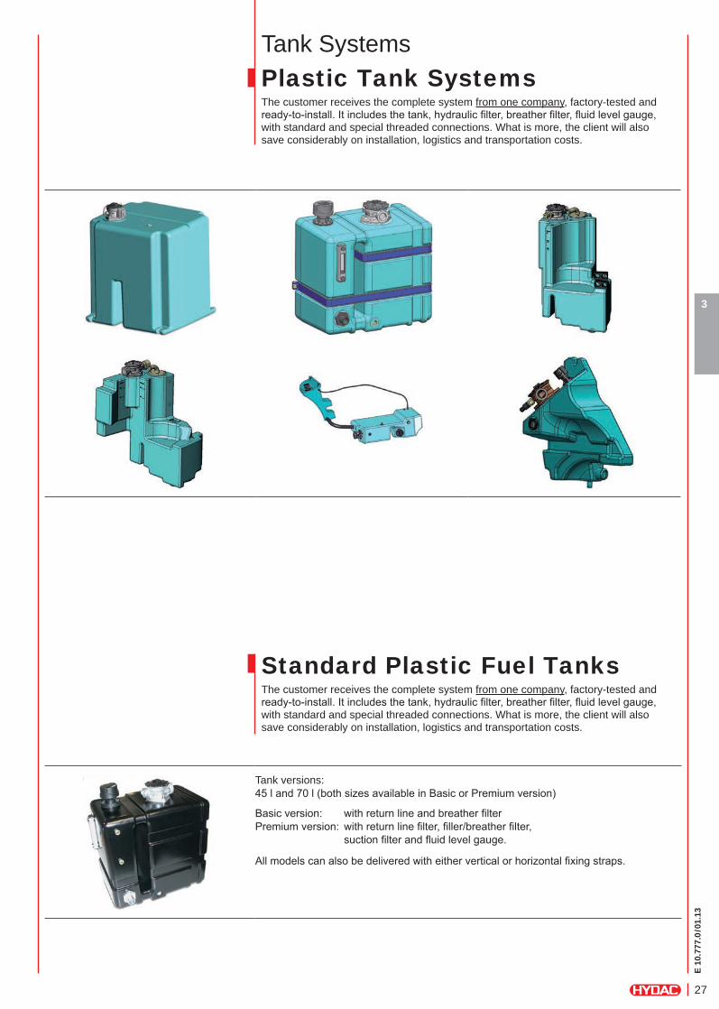
Tank SystemsPlastic Tank SystemsThe customer receives the complete system from one company, factory-tested and ready-to-install. It includes the tank, hydraulic fi lter, breather fi lter, fl uid level gauge, with standard and special threaded connections. What is more, the client will also save considerably on installation, logistics and transportation costs.
Standard Plastic Fuel TanksThe customer receives the complete system from one company, factory-tested and ready-to-install. It includes the tank, hydraulic fi lter, breather fi lter, fl uid level gauge, with standard and special threaded connections. What is more, the client will also save considerably on installation, logistics and transportation costs.
Tank versions:45 l and 70 l (both sizes available in Basic or Premium version)
Basic version: with return line and breather fi lterPremium version: with return line fi lter, fi ller/breather fi lter, suction fi lter and fl uid level gauge.
All models can also be delivered with either vertical or horizontal fi xing straps.
E 10
.777
.0/0
1.13
28
3
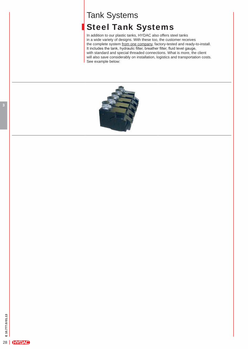
Tank SystemsSteel Tank SystemsIn addition to our plastic tanks, HYDAC also offers steel tanks in a wide variety of designs. With these too, the customer receives the complete system from one company, factory-tested and ready-to-install. It includes the tank, hydraulic fi lter, breather fi lter, fl uid level gauge, with standard and special threaded connections. What is more, the client will also save considerably on installation, logistics and transportation costs. See example below:
E 10
.777
.0/0
1.13
29
4
Pmax[bar]
Qmax[ l/min]
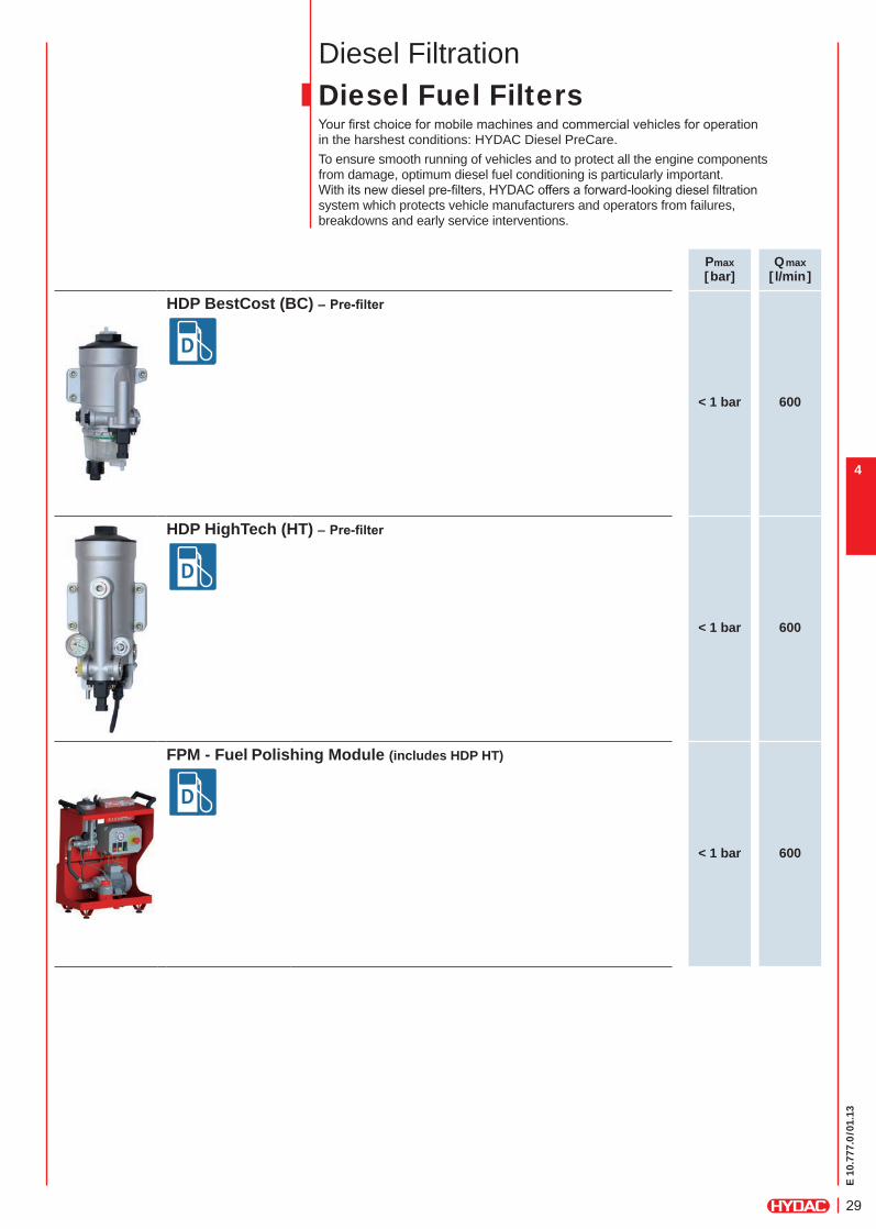
HDP BestCost (BC) – Pre-filter
< 1 bar 600
HDP HighTech (HT) – Pre-filter
< 1 bar 600
FPM - Fuel Polishing Module (includes HDP HT)
< 1 bar 600
Diesel FiltrationDiesel Fuel FiltersYour fi rst choice for mobile machines and commercial vehicles for operation in the harshest conditions: HYDAC Diesel PreCare.To ensure smooth running of vehicles and to protect all the engine components from damage, optimum diesel fuel conditioning is particularly important. With its new diesel pre-fi lters, HYDAC offers a forward-looking diesel fi ltration system which protects vehicle manufacturers and operators from failures, breakdowns and early service interventions.
E 10
.777
.0/0
1.13
30
4
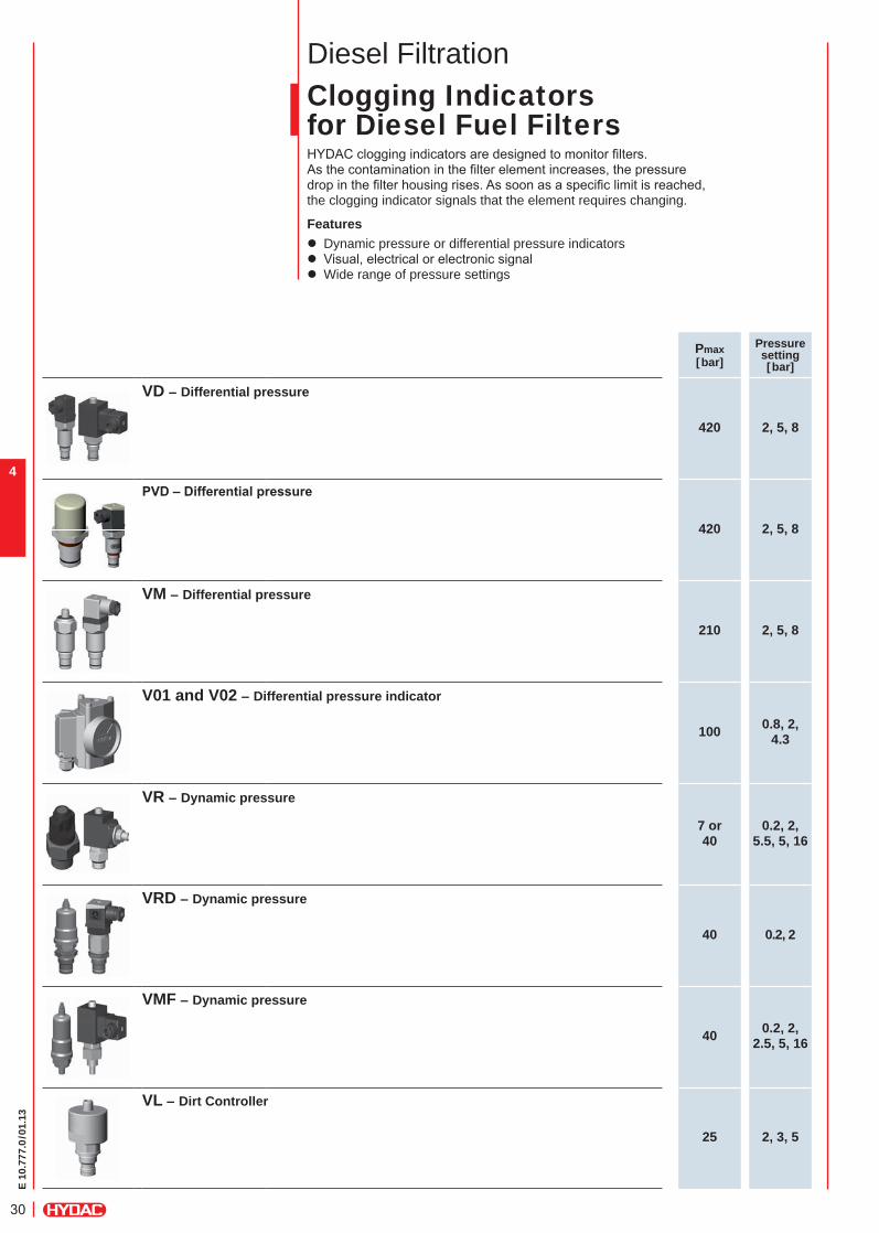
Diesel FiltrationClogging Indicatorsfor Diesel Fuel FiltersHYDAC clogging indicators are designed to monitor fi lters.As the contamination in the fi lter element increases, the pressure drop in the fi lter housing rises. As soon as a specifi c limit is reached, the clogging indicator signals that the element requires changing.
Features z Dynamic pressure or differential pressure indicators z Visual, electrical or electronic signal z Wide range of pressure settings
Pmax[bar]
Pressuresetting[bar]
VD – Differential pressure
420 2, 5, 8
PVD–Differentialpressure
420 2, 5, 8
VM – Differential pressure
210 2, 5, 8
V01 and V02 – Differential pressure indicator
100 0.8, 2, 4.3
VR – Dynamic pressure
7 or40
0.2, 2, 5.5, 5, 16
VRD – Dynamic pressure
40 0.2, 2
VMF – Dynamic pressure
40 0.2, 2, 2.5, 5, 16
VL – Dirt Controller
25 2, 3, 5
E 10
.777
.0/0
1.13
31
5
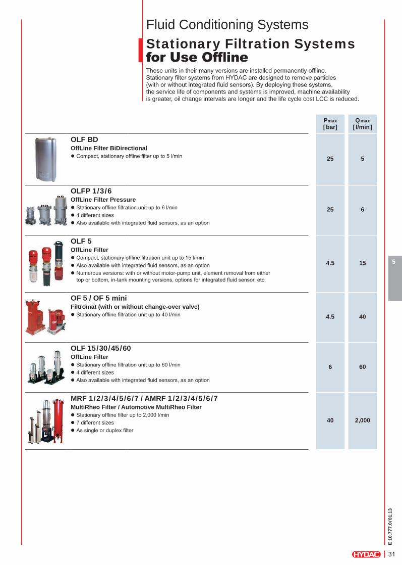
Fluid Conditioning SystemsStationary Filtration Systemsfor Use Offl ine These units in their many versions are installed permanently offl ine. Stationary fi lter systems from HYDAC are designed to remove particles (with or without integrated fl uid sensors). By deploying these systems, the service life of components and systems is improved, machine availability is greater, oil change intervals are longer and the life cycle cost LCC is reduced.
Pmax[bar]
Qmax[ l/min]
OLF BD
25 5OffLine Filter BiDirectional
z Compact, stationary offl ine fi lter up to 5 l/min
OLFP 1/3/6
25 6OffLine Filter Pressure
z Stationary offl ine fi ltration unit up to 6 l/min z 4 different sizes z Also available with integrated fl uid sensors, as an option
OLF 5
4.5 15
OffLine Filter z Compact, stationary offl ine fi ltration unit up to 15 l/min z Also available with integrated fl uid sensors, as an option z Numerous versions: with or without motor-pump unit, element removal from either top or bottom, in-tank mounting versions, options for integrated fl uid sensor, etc.
OF 5 / OF 5 mini
4.5 40Filtromat (with or without change-over valve)
z Stationary offl ine fi ltration unit up to 40 l/min
OLF 15/30/45/60
6 60OffLine Filter
z Stationary offl ine fi ltration unit up to 60 l/min z 4 different sizes z Also available with integrated fl uid sensors, as an option
MRF 1/2/3/4/5/6/7 / AMRF 1/2/3/4/5/6/7
40 2,000
MultiRheo Filter / Automotive MultiRheo Filter z Stationary offl ine fi lter up to 2,000 l/min z 7 different sizes z As single or duplex fi lter

E 10
.777
.0/0
1.13
32
5
Fluid Conditioning SystemsMobile Filtration Systemsfor Use Offl ine HYDAC provides mobile fi ltration systems, specially developed for offl ine fi ltration, for fi ltering, dewatering, degassing and conditioning operating fl uids. By deploying these systems, the service life of components and systems is improved, machine availability is greater, oil change intervals are longer and the life cycle cost LCC is reduced.
Pmax[bar]
Qmax[ l/min]
FCC
3.5 15FluidCarrier Compact
z Mobile off-line fi ltration unit z Up to 15 l/min z Tank volume: 70 l
OF 7
3.5 15Filtration Unit
z Portable off-line fi ltration unit z Up to 15 l/min
FT 5
4.5 40Barrel Transportation and Filtration Trolley
z Up to 40 l/min z For standard 200 l barrel
OF 5 mobile
4.5 40Filtromat (with or without change-over valve)
z Mobile off-line fi ltration unit z Up to 40 l/min z Also available with integrated fl uid sensors, as an option
OF 5 with FCU
4.5 40Filtromat (with or without change-over valve)
z Stationary offl ine fi lter up to 2,000 l/min z 7 different sizes z As single or duplex fi lter
TW 5
4.5 40Mobile Oil Transport and Filtration Unit (with or without change-over valve)
z Mobile off-line fi ltration unit z Up to 40 l/min z Tank volume: 200 l
FCM
10 100FluidCleaner Mobil
z Mobile off-line fi ltration unit z Up to 100 l/min
OFU
10 100OfflineFiltrationUnit
z Filter Pump Transfer Unit z Up to 100 l/min
E 10
.777
.0/0
1.13
33
5
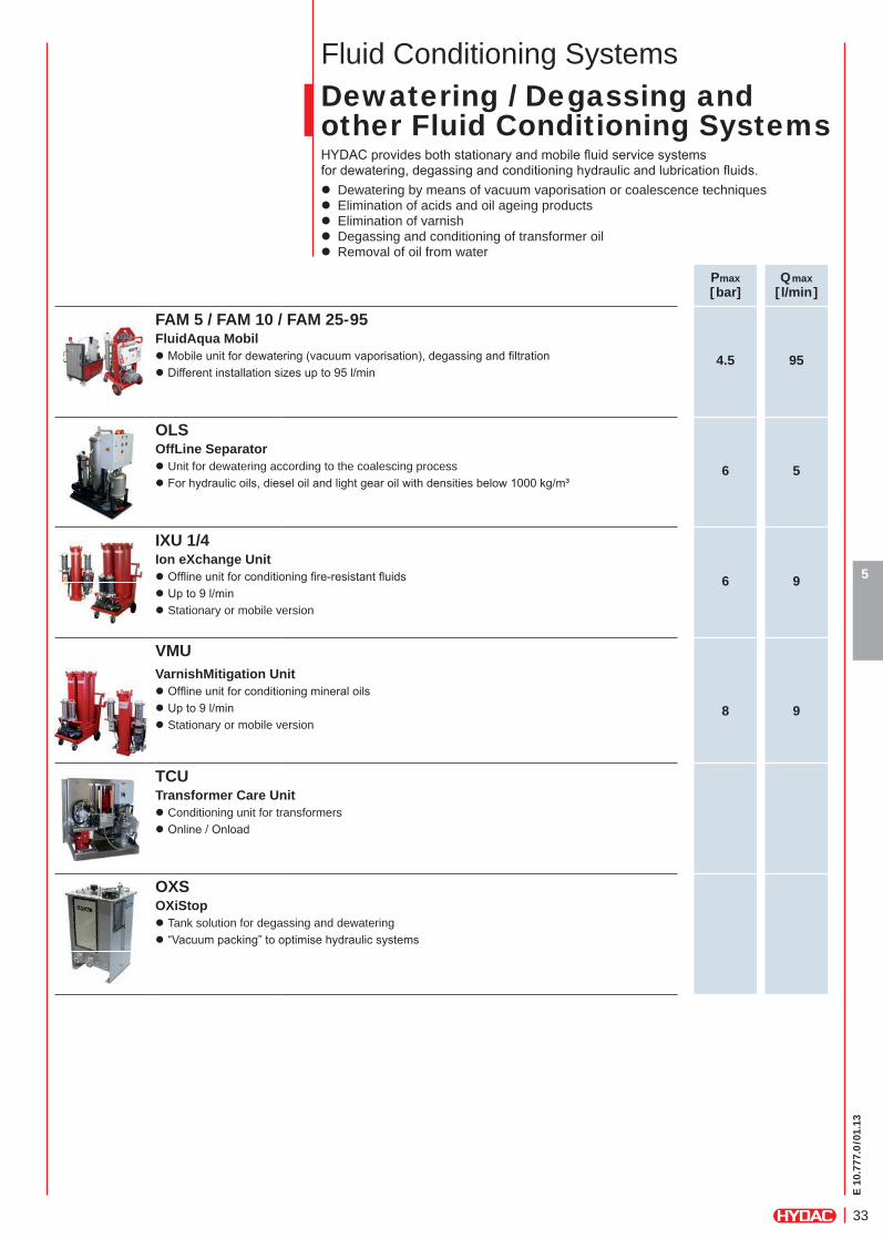
Fluid Conditioning SystemsDewatering / Degassing andother Fluid Conditioning SystemsHYDAC provides both stationary and mobile fl uid service systems for dewatering, degassing and conditioning hydraulic and lubrication fl uids.
z Dewatering by means of vacuum vaporisation or coalescence techniques z Elimination of acids and oil ageing products z Elimination of varnish z Degassing and conditioning of transformer oil z Removal of oil from water
Pmax[bar]
Qmax[ l/min]
FAM 5 / FAM 10 / FAM 25-95
4.5 95FluidAqua Mobil
z Mobile unit for dewatering (vacuum vaporisation), degassing and fi ltration z Different installation sizes up to 95 l/min
OLS
6 5OffLine Separator
z Unit for dewatering according to the coalescing process z For hydraulic oils, diesel oil and light gear oil with densities below 1000 kg/m³
IXU 1/4
6 9Ion eXchange Unit
z Offl ine unit for conditioning fi re-resistant fl uids z Up to 9 l/min z Stationary or mobile version
VMUVarnishMitigation Unit
z Offl ine unit for conditioning mineral oils z Up to 9 l/min z Stationary or mobile version
8 9
TCUTransformer Care Unit
z Conditioning unit for transformers z Online / Onload
OXSOXiStop
z Tank solution for degassing and dewatering z “Vacuum packing” to optimise hydraulic systems

E 10
.777
.0/0
1.13
34
5
E 10
.777
.0/0
1.13
35
6
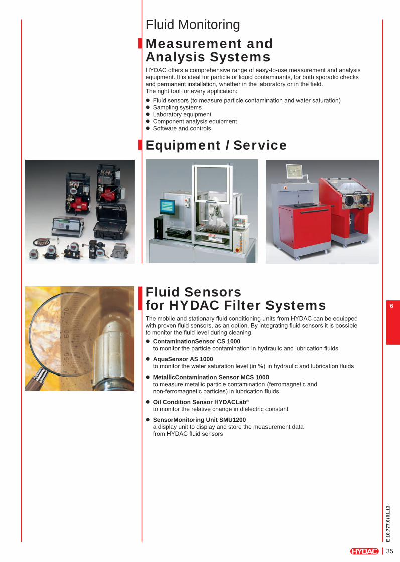
Fluid MonitoringMeasurement and Analysis SystemsHYDAC offers a comprehensive range of easy-to-use measurement and analysis equipment. It is ideal for particle or liquid contaminants, for both sporadic checks and permanent installation, whether in the laboratory or in the fi eld. The right tool for every application:
z Fluid sensors (to measure particle contamination and water saturation) z Sampling systems z Laboratory equipment z Component analysis equipment z Software and controls
Fluid Sensors for HYDAC Filter SystemsThe mobile and stationary fl uid conditioning units from HYDAC can be equipped with proven fl uid sensors, as an option. By integrating fl uid sensors it is possible to monitor the fl uid level during cleaning.
z ContaminationSensor CS 1000 to monitor the particle contamination in hydraulic and lubrication fl uids
z AquaSensor AS 1000 to monitor the water saturation level (in %) in hydraulic and lubrication fl uids
z MetallicContamination Sensor MCS 1000 to measure metallic particle contamination (ferromagnetic and non-ferromagnetic particles) in lubrication fl uids
z Oil Condition Sensor HYDACLab®
to monitor the relative change in dielectric constant
z SensorMonitoring Unit SMU1200 a display unit to display and store the measurement data from HYDAC fl uid sensors
Equipment / Service

E 10
.777
.0/0
1.13
36
6
E 10
.777
.0/0
1.13
37
7
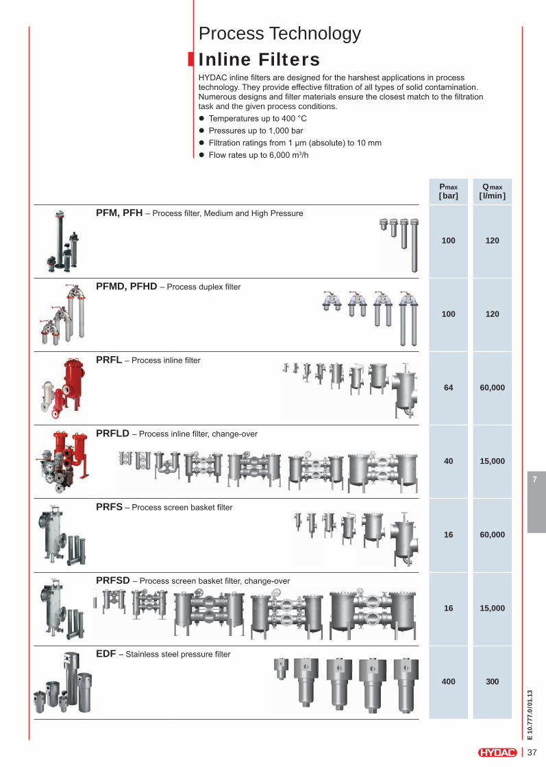
Process TechnologyInline FiltersHYDAC inline fi lters are designed for the harshest applications in process technology. They provide effective fi ltration of all types of solid contamination. Numerous designs and fi lter materials ensure the closest match to the fi ltration task and the given process conditions.
z Temperatures up to 400 °C z Pressures up to 1,000 bar z Filtration ratings from 1 µm (absolute) to 10 mm z Flow rates up to 6,000 m3/h
Pmax[bar]
Qmax[ l/min]
PFM, PFH – Process fi lter, Medium and High Pressure
100 120
PFMD, PFHD – Process duplex fi lter
100 120
PRFL – Process inline fi lter
64 60,000
PRFLD – Process inline fi lter, change-over
40 15,000
PRFS – Process screen basket fi lter
16 60,000
PRFSD – Process screen basket fi lter, change-over
16 15,000
EDF – Stainless steel pressure fi lter
400 300
E 10
.777
.0/0
1.13
38
7
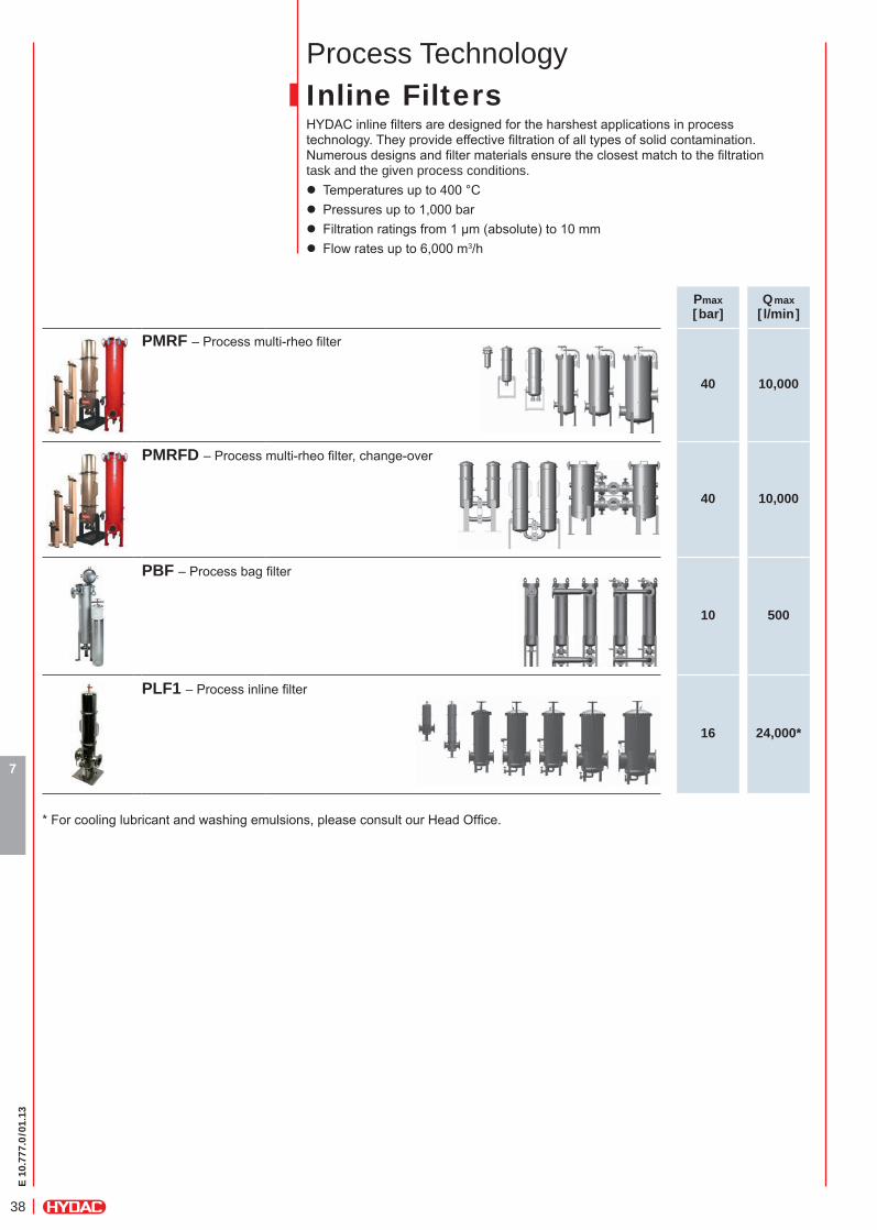
Process TechnologyInline FiltersHYDAC inline fi lters are designed for the harshest applications in process technology. They provide effective fi ltration of all types of solid contamination. Numerous designs and fi lter materials ensure the closest match to the fi ltration task and the given process conditions.
z Temperatures up to 400 °C z Pressures up to 1,000 bar z Filtration ratings from 1 µm (absolute) to 10 mm z Flow rates up to 6,000 m3/h
Pmax[bar]
Qmax[ l/min]
PMRF – Process multi-rheo fi lter
40 10,000
PMRFD – Process multi-rheo fi lter, change-over
40 10,000
PBF – Process bag fi lter
10 500
PLF1 – Process inline fi lter
16 24,000*
* For cooling lubricant and washing emulsions, please consult our Head Offi ce.
E 10
.777
.0/0
1.13
39
7
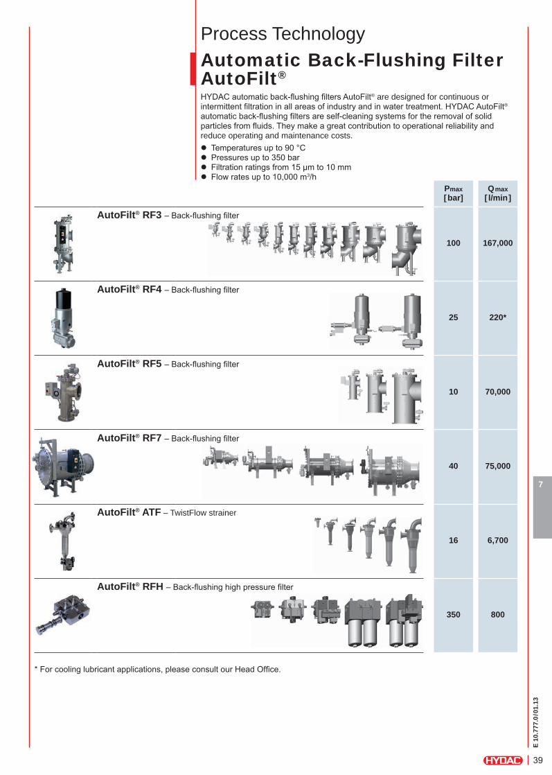
Process TechnologyAutomatic Back-Flushing Filter AutoFilt®
HYDAC automatic back-fl ushing fi lters AutoFilt® are designed for continuous or intermittent fi ltration in all areas of industry and in water treatment. HYDAC AutoFilt® automatic back-fl ushing fi lters are self-cleaning systems for the removal of solid particles from fl uids. They make a great contribution to operational reliability and reduce operating and maintenance costs.
z Temperatures up to 90 °C z Pressures up to 350 bar z Filtration ratings from 15 µm to 10 mm z Flow rates up to 10,000 m3/h
Pmax[bar]
Qmax[ l/min]
AutoFilt® RF3 – Back-fl ushing fi lter
100 167,000
AutoFilt® RF4 – Back-fl ushing fi lter
25 220*
AutoFilt® RF5 – Back-fl ushing fi lter
10 70,000
AutoFilt® RF7 – Back-fl ushing fi lter
40 75,000
AutoFilt® ATF – TwistFlow strainer
16 6,700
AutoFilt® RFH – Back-fl ushing high pressure fi lter
350 800
* For cooling lubricant applications, please consult our Head Offi ce.
E 10
.777
.0/0
1.13
40
7
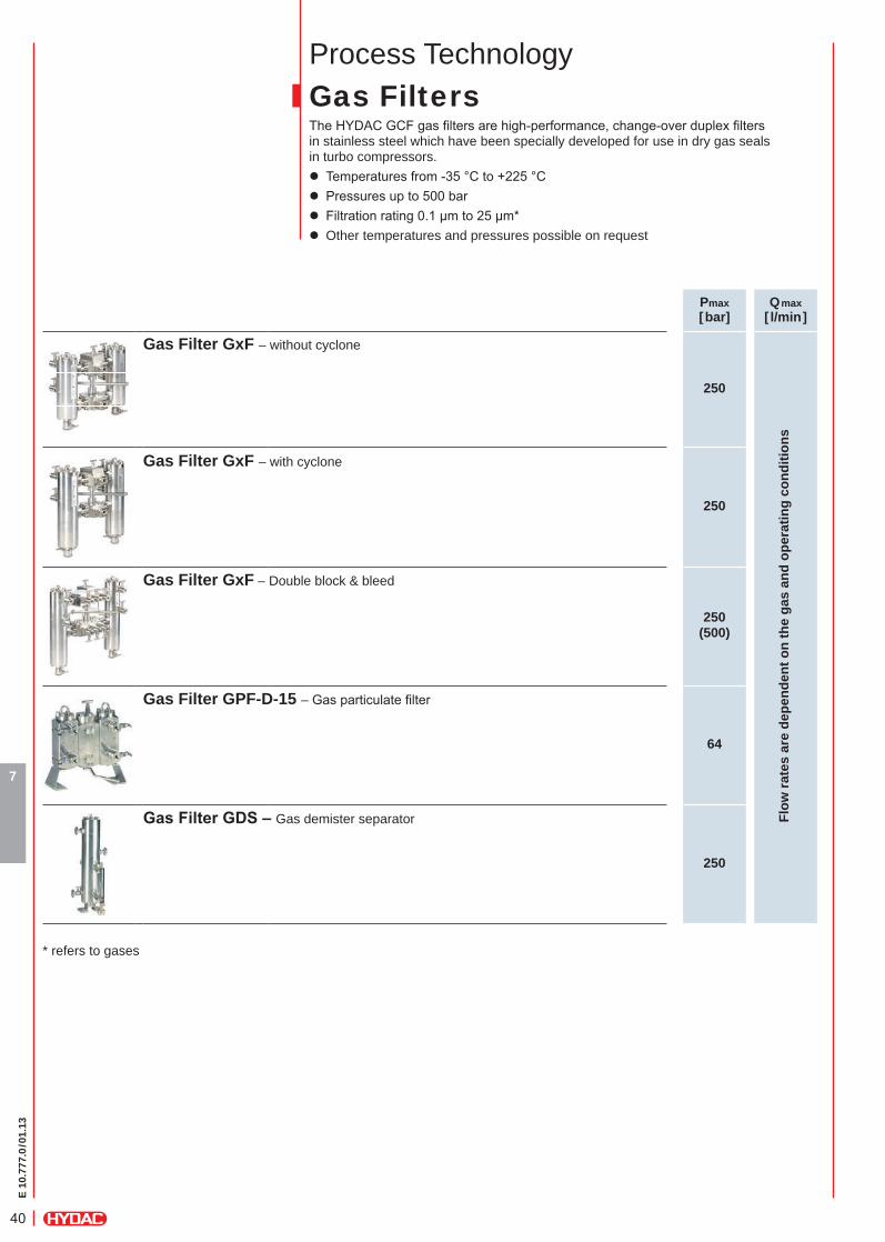
Process TechnologyGas FiltersThe HYDAC GCF gas fi lters are high-performance, change-over duplex fi lters in stainless steel which have been specially developed for use in dry gas seals in turbo compressors.
z Temperatures from -35 °C to +225 °C z Pressures up to 500 bar z Filtration rating 0.1 µm to 25 µm* z Other temperatures and pressures possible on request
Pmax[bar]
Qmax[ l/min]
Gas Filter GxF – without cyclone
250
Flow
rate
s ar
e de
pend
ent o
n th
e ga
s an
d op
erat
ing
cond
ition
s
Gas Filter GxF – with cyclone
250
Gas Filter GxF – Double block & bleed
250(500)
Gas Filter GPF-D-15 – Gas particulate fi lter
64
GasFilterGDS–Gas demister separator
250
* refers to gases
E 10
.777
.0/0
1.13
41
7
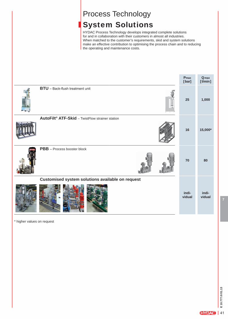
Process TechnologySystem SolutionsHYDAC Process Technology develops integrated complete solutions for and in collaboration with their customers in almost all industries. When matched to the customer’s requirements, skid and system solutions make an effective contribution to optimising the process chain and to reducing the operating and maintenance costs.
Pmax[bar]
Qmax[ l/min]
BTU – Back-fl ush treatment unit
25 1,000
AutoFilt® ATF-Skid – TwistFlow strainer station
16 15,000*
PBB – Process booster block
70 80
Customised system solutions available on request
indi-vidual
indi-vidual
* higher values on request
E 10
.777
.0/0
1.13
42
7
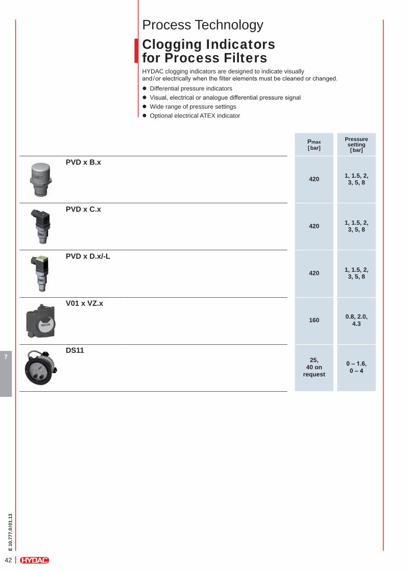
Process TechnologyClogging Indicators for Process FiltersHYDAC clogging indicators are designed to indicate visually and/or electrically when the fi lter elements must be cleaned or changed.
z Differential pressure indicators z Visual, electrical or analogue differential pressure signal z Wide range of pressure settings z Optional electrical ATEX indicator
Pmax[bar]
Pressuresetting[bar]
PVD x B.x
420 1, 1.5, 2, 3, 5, 8
PVD x C.x
420 1, 1.5, 2, 3, 5, 8
PVD x D.x/-L
420 1, 1.5, 2, 3, 5, 8
V01 x VZ.x
160 0.8, 2.0, 4.3
DS1125,
40 on request
0–1.6,0–4
E 10
.777
.0/0
1.13
43
8
9
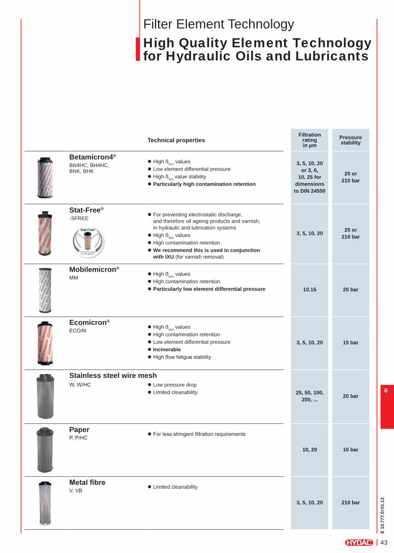
Filter Element TechnologyHigh Quality Element Technology for Hydraulic Oils and Lubricants
Technical properties Filtration
rating in µm
Pressure stability
Betamicron4®
3, 5, 10, 20or 3, 6,
10, 25 for dimensions to DIN 24550
20 or210 bar
BN4HC, BH4HC, BNK, BHK
z High ßx(c) values z Low element differential pressure z High ßx(c) value stability z Particularly high contamination retention
Stat-Free®
3, 5, 10, 20 20 or210 bar
-SFREE z For preventing electrostatic discharge, and therefore oil ageing products and varnish, in hydraulic and lubrication systems
z High ßx(c) values z High contamination retention z We recommend this is used in conjunction with IXU (for varnish removal)
Mobilemicron®
10.15 20 bar
MM z High ßx(c) values z High contamination retention z Particularly low element differential pressure
Ecomicron®
3, 5, 10, 20 15 bar
ECO/N z High ßx(c) values z High contamination retention z Low element differential pressure z Incinerable z High fl ow fatigue stability
Stainless steel wire mesh
25, 50, 100, 200, ... 20 bar
W, W/HC z Low pressure drop z Limited cleanability
Paper
10, 20 10 bar
P, P/HC z For less stringent fi ltration requirements
Metalfibre
3, 5, 10, 20 210 bar
V, VB z Limited cleanability
E 10
.777
.0/0
1.13
44
8
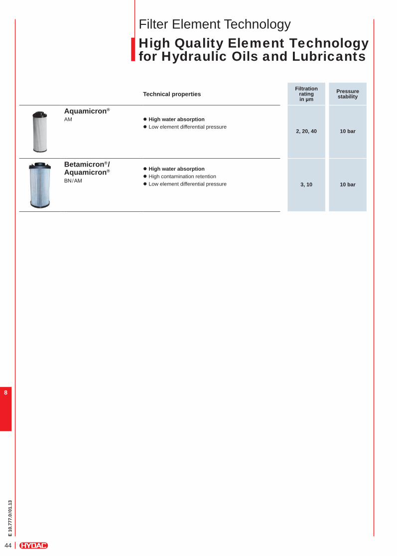
Filter Element TechnologyHigh Quality Element Technology for Hydraulic Oils and Lubricants
Technical properties Filtration
rating in µm
Pressure stability
Aquamicron®
2, 20, 40 10 bar
AM z High water absorption z Low element differential pressure
Betamicron®/Aquamicron®
BN/AM3, 10 10 bar
z High water absorption z High contamination retention z Low element differential pressure

E 10
.777
.0/0
1.13
45
8
9
Filter Element TechnologyHigh Quality Element Technology for Hydraulic Oils and Lubricants
Effi cient Element Technology for Systems with Consistently High Contamination Intake
Technical properties Filtration
rating in µm
Dimicron®
N15DM z Filtration effi ciency: ß(x) > 1,000 at Δp = 2 bar z Combination of depth and surface fi ltration= high level of cleanliness in single pass
z Extremely high contamination retention capacity= formation of a fi lter cake with robust support provided by membrane to prevent material migration
2, 5, 10, 20, 30
N10DM 2, 5, 10, 20
N5DM z ß(x) > 1,000 at Δp = 2.5 bar) z Extremely high contamination retention capacity
2, 5, 10, 20
Trimicron®
3
TMN1
z Combined pleated and spun spray elements z Removal of oil ageing products, fi ne particles and water
Technical properties Filtration
rating in µm
Flexmicron Premium®
FM-P
1–90
z Graduated depth fi ltration in thin media layer = Long lifetime even with fl uids which are diffi cult to fi lter
z Low initial differential pressure = High contamination retention capacity z Robust support for non-woven media = Prevents material migration during pulsation
z Compact housing with high fl ow rates z Standard dimensions, compatible with other manufacturers
Flexmicron Standard®
FM-S z Graduated depth fi ltration = High level of cleanliness in a single pass z Thick layer of fi lter media = High retention capacity for contamination z Standard dimensions, compatible with other manufacturers
Flexmicron Economy®
FM-E
Wombat
1–90
WB z Bag fi lter with pleated fi lter area = High contamination retention capacity z Flow direction from in to out = No transfer of contamination onto the clean side when changing fi lter element
z Good fl uid compatibility and temperature resistance
E 10
.777
.0/0
1.13
46
8
Filter Element TechnologyHigh Quality Element Technology for Diesel Fuels
Technical properties Filtration rating ISO 19438
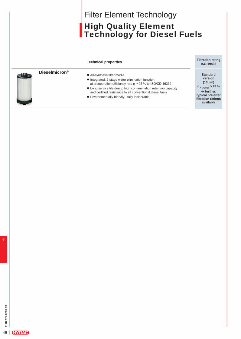
Dieselmicron®Standard version (10 µm)
ƞ> 10 µm (c) > 99 %à further,
typical pre-filter filtration ratings
available
z All-synthetic fi lter media z Integrated, 2-stage water elimination functionat a separation effi ciency rate ƞ > 95 % to ISO/CD 16332
z Long service life due to high contamination retention capacity and certifi ed resistance to all conventional diesel fuels
z Environmentally friendly - fully incinerable
E 10
.777
.0/0
1.13
47
8
9
Filter Element TechnologyFilter Element Technology for Process Technology
Technical properties
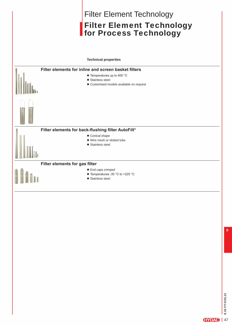
Filterelementsforinlineandscreenbasketfilters z Temperatures up to 400 °C z Stainless steel z Customised models available on request
Filterelementsforback-flushingfilterAutoFilt® z Conical shape z Wire mesh or slotted tube z Stainless steel
Filterelementsforgasfilter z End caps crimped z Temperatures -35 °C to +225 °C z Stainless steel
E 10
.777
.0/0
1.13
48
8
Filter Element TechnologyFilter Materials for Process Technology
Technical properties Filtration rating
Permitted differential pressure
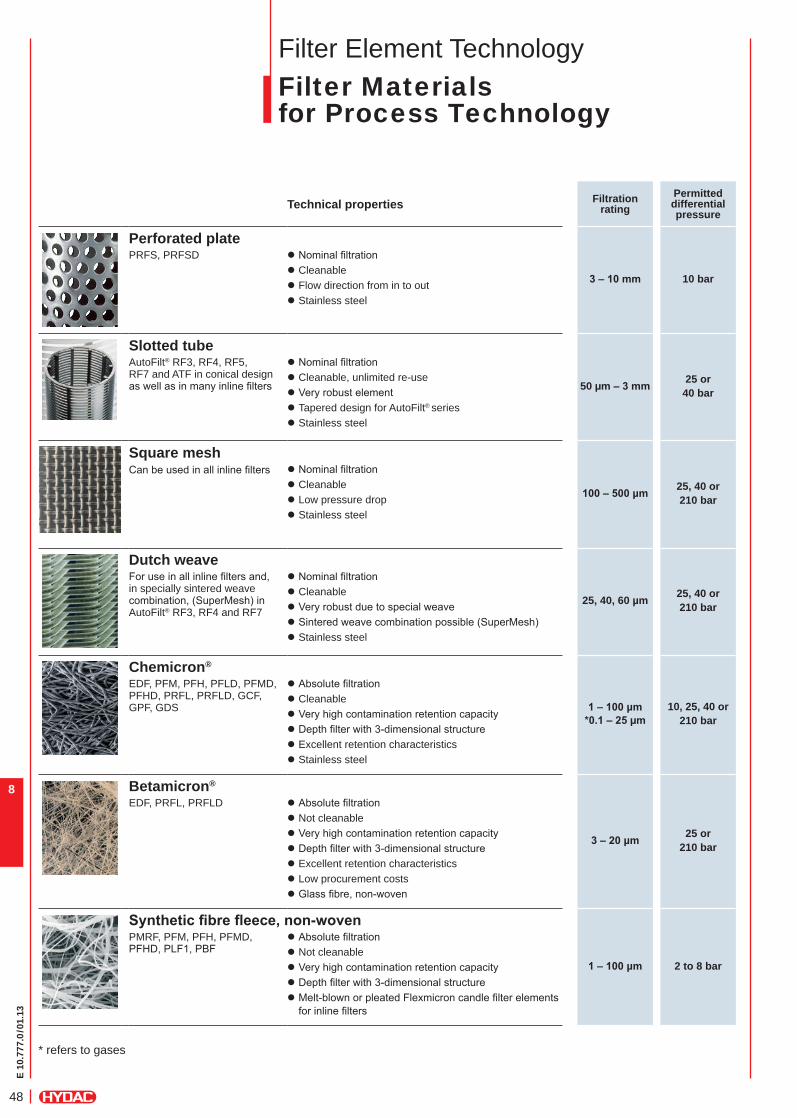
Perforated plate
3–10mm 10 bar
PRFS, PRFSD z Nominal fi ltration z Cleanable z Flow direction from in to out z Stainless steel
Slotted tube
50 µm–3mm 25 or40 bar
AutoFilt® RF3, RF4, RF5, RF7 and ATF in conical design as well as in many inline fi lters
z Nominal fi ltration z Cleanable, unlimited re-use z Very robust element z Tapered design for AutoFilt® series z Stainless steel
Square meshCan be used in all inline fi lters
100–500µm 25, 40 or 210 bar
z Nominal fi ltration z Cleanable z Low pressure drop z Stainless steel
Dutch weave
25, 40, 60 µm 25, 40 or 210 bar
For use in all inline fi lters and, in specially sintered weave combination, (SuperMesh) in AutoFilt® RF3, RF4 and RF7
z Nominal fi ltration z Cleanable z Very robust due to special weave z Sintered weave combination possible (SuperMesh) z Stainless steel
Chemicron®
1–100µm*0.1–25µm
10, 25, 40 or 210 bar
EDF, PFM, PFH, PFLD, PFMD, PFHD, PRFL, PRFLD, GCF, GPF, GDS
z Absolute fi ltration z Cleanable z Very high contamination retention capacity z Depth fi lter with 3-dimensional structure z Excellent retention characteristics z Stainless steel
Betamicron®
3–20µm 25 or 210 bar
EDF, PRFL, PRFLD z Absolute fi ltration z Not cleanable z Very high contamination retention capacity z Depth fi lter with 3-dimensional structure z Excellent retention characteristics z Low procurement costs z Glass fi bre, non-woven
Syntheticfibrefleece,non-woven
1–100µm 2 to 8 bar
PMRF, PFM, PFH, PFMD, PFHD, PLF1, PBF
z Absolute fi ltration z Not cleanable z Very high contamination retention capacity z Depth fi lter with 3-dimensional structure z Melt-blown or pleated Flexmicron candle fi lter elements for inline fi lters
* refers to gases
E 10
.777
.0/0
1.13
49
9
HYDAC Expertise –Understanding FluidsWhat is it all about?Once the direct connection between fl uid condition and the profi tability and effi ciency of hydraulic and lubrication systems is recognised, the action required becomes obvious:
Cooling, continuous online monitoring and a well-engineered fi ltration concept guarantee the effi ciency and operational reliability of the entire system.
In addition to “fi lter” components, HYDAC also provides modern solutions in the areas of cooling and condition monitoring which are specifi c to your system. Only by taking an integrated approach is it possible to improve the condition of the fl uid used and to reduce the Life Cycle Costs.
HYDAC prides itself on understanding fl uids to make life easier for system operators through the use of relevant product solutions.
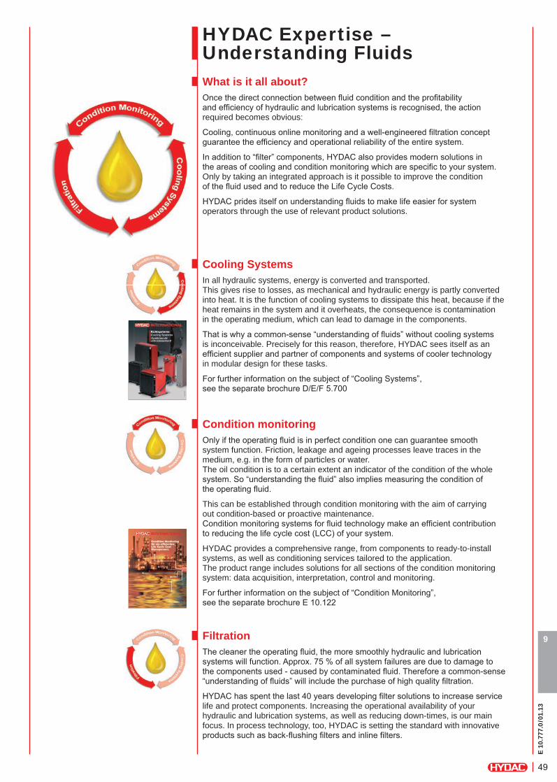
Cooling SystemsIn all hydraulic systems, energy is converted and transported. This gives rise to losses, as mechanical and hydraulic energy is partly converted into heat. It is the function of cooling systems to dissipate this heat, because if the heat remains in the system and it overheats, the consequence is contamination in the operating medium, which can lead to damage in the components.
That is why a common-sense “understanding of fl uids” without cooling systems is inconceivable. Precisely for this reason, therefore, HYDAC sees itself as an effi cient supplier and partner of components and systems of cooler technology in modular design for these tasks.
For further information on the subject of “Cooling Systems”, see the separate brochure D/E/F 5.700
Condition monitoringOnly if the operating fl uid is in perfect condition one can guarantee smooth system function. Friction, leakage and ageing processes leave traces in the medium, e.g. in the form of particles or water.The oil condition is to a certain extent an indicator of the condition of the whole system. So “understanding the fl uid” also implies measuring the condition of the operating fl uid.
This can be established through condition monitoring with the aim of carrying out condition-based or proactive maintenance.Condition monitoring systems for fl uid technology make an effi cient contribution to reducing the life cycle cost (LCC) of your system.
HYDAC provides a comprehensive range, from components to ready-to-install systems, as well as conditioning services tailored to the application. The product range includes solutions for all sections of the condition monitoring system: data acquisition, interpretation, control and monitoring.
For further information on the subject of “Condition Monitoring”, see the separate brochure E 10.122
Filtration The cleaner the operating fl uid, the more smoothly hydraulic and lubrication systems will function. Approx. 75 % of all system failures are due to damage to the components used - caused by contaminated fl uid. Therefore a common-sense “understanding of fl uids” will include the purchase of high quality fi ltration.
HYDAC has spent the last 40 years developing fi lter solutions to increase service life and protect components. Increasing the operational availability of your hydraulic and lubrication systems, as well as reducing down-times, is our main focus. In process technology, too, HYDAC is setting the standard with innovative products such as back-fl ushing fi lters and inline fi lters.
E 10
.777
.0/0
1.13
50
9
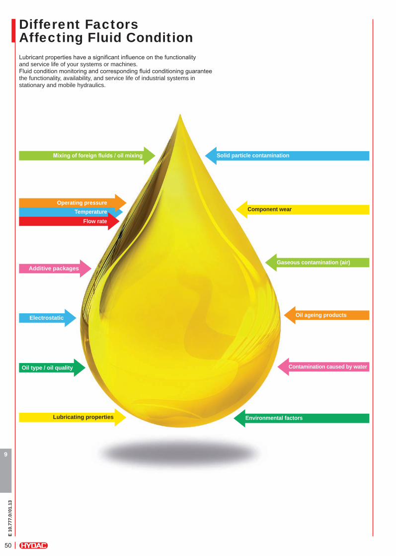
Lubricant properties have a signifi cant infl uence on the functionality and service life of your systems or machines. Fluid condition monitoring and corresponding fl uid conditioning guarantee the functionality, availability, and service life of industrial systems in stationary and mobile hydraulics.
Different Factors Affecting Fluid Condition
Additive packages
Oil type / oil quality
Electrostatic
Mixingofforeignfluids/oilmixing
Operating pressureTemperature
Flow rate
Lubricating properties
Solid particle contamination
Oil ageing products
Contamination caused by water
Environmental factors
Gaseous contamination (air)
Component wear
E 10
.777
.0/0
1.13
51
9
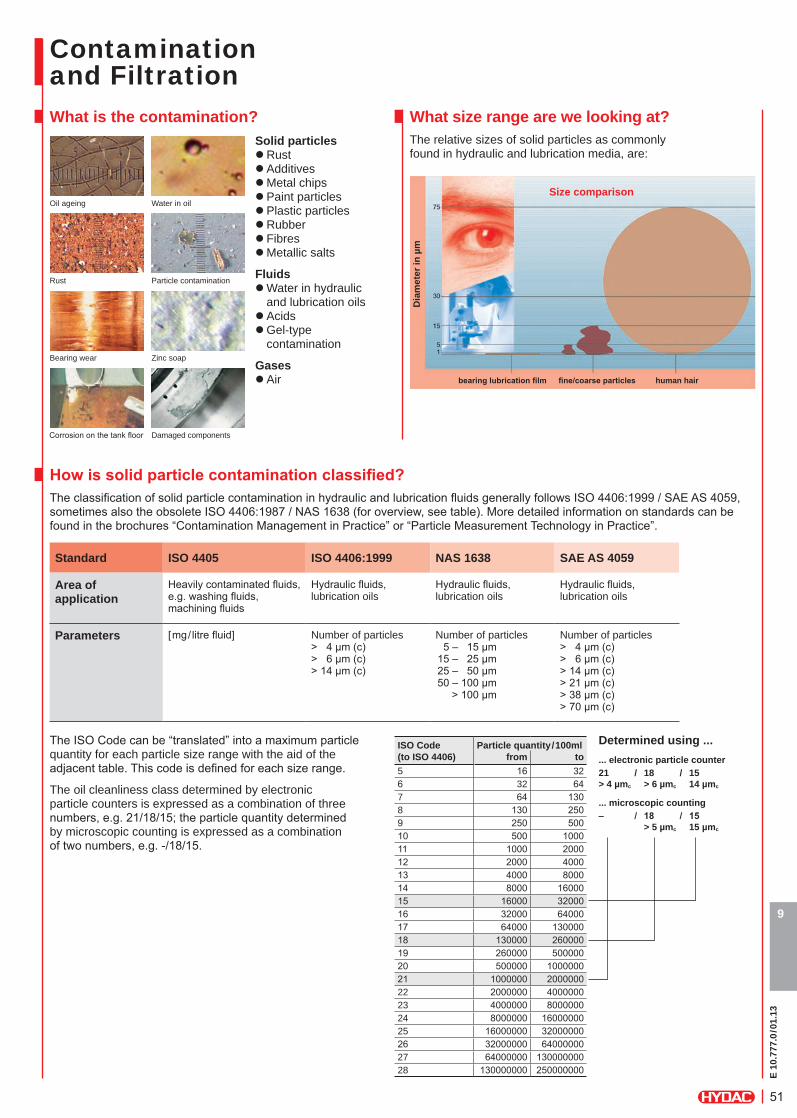
Contamination and FiltrationWhat is the contamination?
Solid particles zRust zAdditives zMetal chips zPaint particles zPlastic particles zRubber z Fibres zMetallic salts
Fluids zWater in hydraulic and lubrication oils zAcids zGel-type contamination
Gases zAir
Howissolidparticlecontaminationclassified?The classification of solid particle contamination in hydraulic and lubrication fluids generally follows ISO 4406:1999 / SAE AS 4059, sometimes also the obsolete ISO 4406:1987 / NAS 1638 (for overview, see table). More detailed information on standards can be found in the brochures “Contamination Management in Practice” or “Particle Measurement Technology in Practice”.
Standard ISO 4405 ISO 4406:1999 NAS 1638 SAE AS 4059
Area of application
Heavily contaminated fluids, e.g. washing fluids, machining fluids
Hydraulic fluids, lubrication oils
Hydraulic fluids, lubrication oils
Hydraulic fluids, lubrication oils
Parameters [mg/ litre fluid] Number of particles > 4 µm (c) > 6 µm (c) > 14 µm (c)
Number of particles 5 – 15 µm 15 – 25 µm 25 – 50 µm 50 – 100 µm > 100 µm
Number of particles > 4 µm (c) > 6 µm (c) > 14 µm (c) > 21 µm (c) > 38 µm (c) > 70 µm (c)
The ISO Code can be “translated” into a maximum particle quantity for each particle size range with the aid of the adjacent table. This code is defined for each size range.
The oil cleanliness class determined by electronic particle counters is expressed as a combination of three numbers, e.g. 21/18/15; the particle quantity determined by microscopic counting is expressed as a combination of two numbers, e.g. -/18/15.
What size range are we looking at?The relative sizes of solid particles as commonly found in hydraulic and lubrication media, are:
bearinglubricationfilm fine/coarseparticles human hair
Dia
met
er in
µm
Size comparisonOil ageing
Rust
Bearing wear
Corrosion on the tank floor
Water in oil
Particle contamination
Zinc soap
Damaged components
Determined using ...... electronic particle counter21 / 18 / 15 > 4 µmc > 6 µmc 14 µmc
... microscopic counting– / 18 / 15 > 5 µmc 15 µmc
ISO Code Particle quantity/100ml(to ISO 4406) from to5 16 326 32 647 64 1308 130 2509 250 50010 500 100011 1000 200012 2000 400013 4000 800014 8000 1600015 16000 3200016 32000 6400017 64000 13000018 130000 26000019 260000 50000020 500000 100000021 1000000 200000022 2000000 400000023 4000000 800000024 8000000 1600000025 16000000 3200000026 32000000 6400000027 64000000 13000000028 130000000 250000000
E 10
.777
.0/0
1.13
52
9
Contamination and FiltrationWhat damage can the contamination cause?1. Abrasion caused by particles between reciprocating surfaces2. Erosion caused by particles and high fluid velocity3. Adhesion caused by metal-to-metal friction (loss of fluid)4. Surface fatigue surfaces damaged by particles are subjected to repeated stress5. Corrosion caused by water or chemicals (not included below)
ConsequencesThe contamination in the system and the associated mechanical damage patterns result in:
z Poor system cleanliness class z System failures z High level of component wear z Cavitation z Formation of sludge (from formation of oil ageing products, such as varnish)
z Reduction in thickness of dynamic lubrication film z Shorter oil service life due to accelerated oil ageing
Which cleanliness classes are recommended by component manufacturers?Component manufacturers, too, recognise the problem of particle contamination and specify guidelines for the cleanliness of systems.
Cleanliness requirements for lubricating and hydraulic components
Low / medium pressure > 140 bar
(moderate conditions)
High pressure 140 ... 200 bar
(low / medium under poor conditions1))
Very high pressure > 200 bar
(high pressure under poor conditions)
ISO 4406:1999 Target cleanliness
classFiltration rating
in µmISO 4406:1999
Target cleanliness class
Filtration rating in µm
ISO 4406:1999 Target cleanliness
classFiltration rating
in µm
Pumps / motorsGear or vane 20/18/15 20 19/17/14 10 18/16/13 5Piston 19/17/14 10 18/16/13 5 17/15/12 3Variable vane 18/16/13 5 17/15/12 3 not applicable not applicableVariable piston 18/16/13 5 17/15/12 3 16/14/11 3 2)
DrivesCylinders 20/18/15 20 19/17/14 10 18/16/13 5Hydrostatic drives 16/15/12 3 16/14/11 3 2) 15/13/10 3 2)
Test rigs 15/13/10 3 2) 15/13/10 3 2) 15/13/10 3 2)
ValvesCheck valve 20/18/15 20 20/18/15 20 19/17/14 10Directional valve 20/18/15 20 19/17/14 10 18/16/13 5Standardflowcontrolvalve 20/18/15 20 19/17/14 10 18/16/13 5Poppet valve 19/17/14 10 18/16/13 5 17/15/12 3Proportional valve 17/15/12 3 17/15/12 3 16/14/11 3 2)
Servo valve 16/14/11 3 2) 16/14/11 3 2) 15/13/10 3 2)
BearingsPlain bearing3) 18/15/12 10 not applicable not applicable not applicable not applicableGears3) 17/15/12 10 not applicable not applicable not applicable not applicableBall bearing3) 15/13/10 3 2) not applicable not applicable not applicable not applicableRoller bearing3) 16/14/11 5 not applicable not applicable not applicable not applicable
1) Poor conditions may include flow rate fluctuations, pressure spikes, frequent cold starts, extremely high ingress of contamination, or the presence of water.2) Two or more system filters with the recommended filtration rating may be required to achieve and maintain the desired target cleanliness class.3) Valid for the average diameter range.
For system cleanliness, we recommend working at one class better than the cleanliness class required for the most sensitive component.Fillingfiltration/flushingfiltrationtobeatleastonefiltrationclassfinerthanthesystemfilter.According to DIN 51524, a cleanliness of ISO 21/19/16 must be guaranteed for new hydraulic oil.
What are the costs to me of such damage?The damage outlined has a negative affect on the maintenance costs of the system. Generally, you can expect a rise in the following costs:
z Spare parts costs z Costs of stoppage times z Guarantee costs and ex gratia payments z Energy costs z Re-working costs z Tooling costs for machining centres z Operating costs of washing machines and test rigs z Working time costs (above all for maintenance personnel)
E 10
.777
.0/0
1.13
53
9
How do I know if contamination has got into my hydraulic or lubrication system and how do I measure it?
1) Permanentonlinefluidmonitoring in hydraulic and lubrication systems and on test rigs (Online Condition Monitoring)
Through the use of permanently installed fl uid sensors, the condition of the system can be continuously monitored online.
This forms the basis of planned availability of systems and components, prevention of unexpected stoppage times and condition-based maintenance.
HYDAC offers an extensive product range of fl uid sensors for recording
zSolid particle contamination zMetallic particles or z Fluid contamination (water)
The measurements can either be displayed and stored directly on the built-in display on the sensor or via a separate display unit. In addition it is also possible to integrate the measurements in the customer's own control system as well as transfer them to a PC.
The data from the connected sensors is displayed online as a table & graphics and is also automatically stored in fi les.
The fi les can be opened again in the software and can be exported in different formats (e.g. MS Excel format, different graphics formats).
Moreover, the graphic currently displayed can be printed using this software.
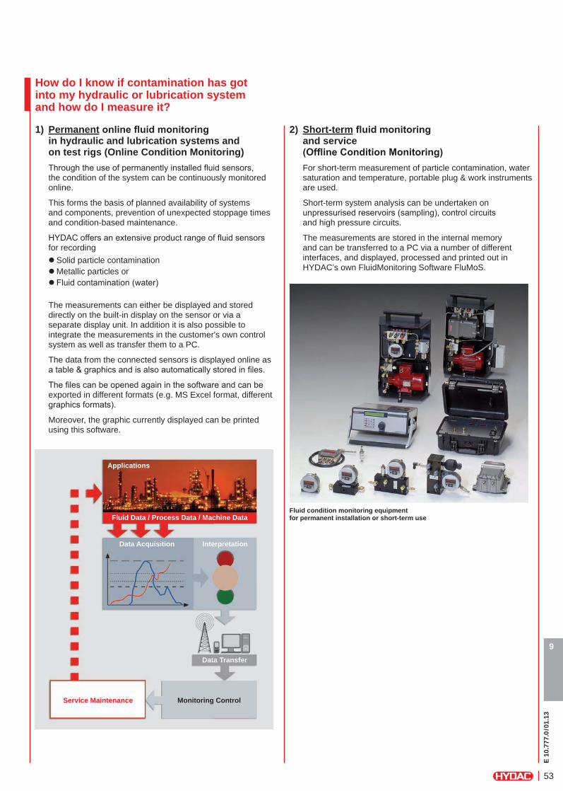
2) Short-termfluidmonitoring and service (OfflineConditionMonitoring)
For short-term measurement of particle contamination, water saturation and temperature, portable plug & work instruments are used.
Short-term system analysis can be undertaken on unpressurised reservoirs (sampling), control circuits and high pressure circuits.
The measurements are stored in the internal memory and can be transferred to a PC via a number of different interfaces, and displayed, processed and printed out in HYDAC’s own FluidMonitoring Software FluMoS.
Fluid condition monitoring equipment for permanent installation or short-term use
Applications
Data Acquisition Interpretation
Data Transfer
Monitoring ControlService Maintenance
Fluid Data / Process Data / Machine Data
E 10
.777
.0/0
1.13
54
9
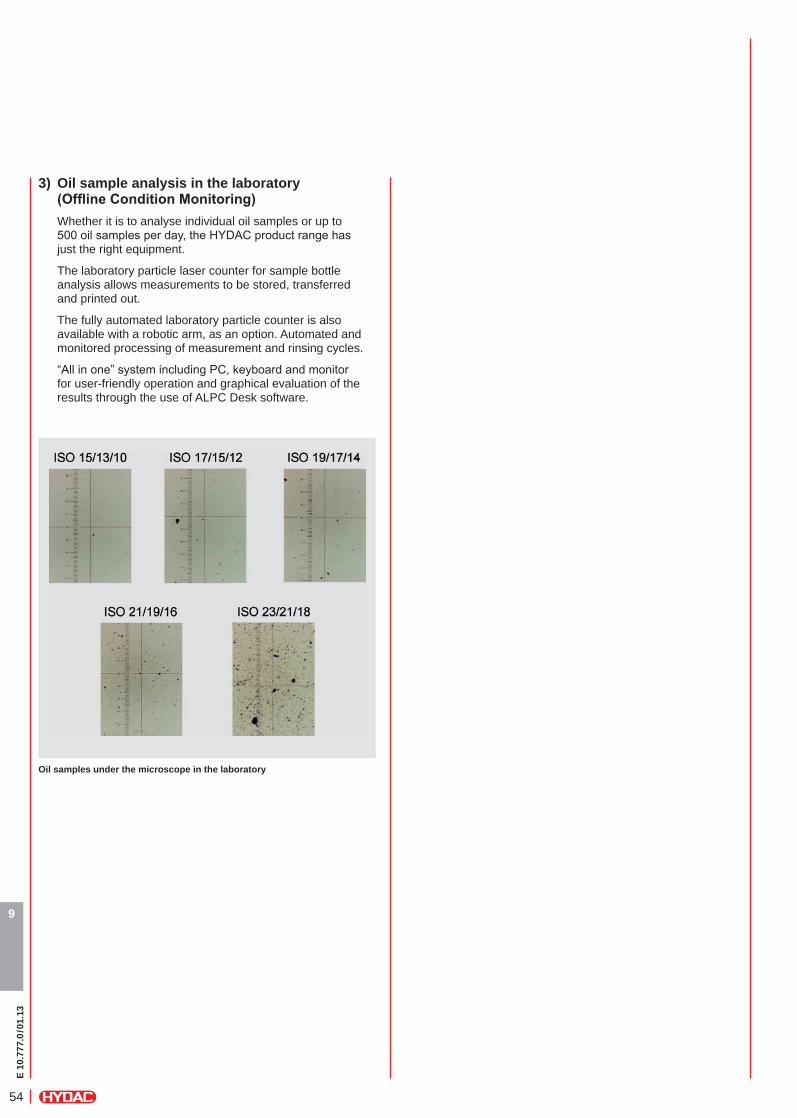
3) Oil sample analysis in the laboratory (OfflineConditionMonitoring)
Whether it is to analyse individual oil samples or up to 500 oil samples per day, the HYDAC product range has just the right equipment.
The laboratory particle laser counter for sample bottle analysis allows measurements to be stored, transferred and printed out.
The fully automated laboratory particle counter is also available with a robotic arm, as an option. Automated and monitored processing of measurement and rinsing cycles.
“All in one” system including PC, keyboard and monitor for user-friendly operation and graphical evaluation of the results through the use of ALPC Desk software.
Oil samples under the microscope in the laboratory
E 10
.777
.0/0
1.13
55
9
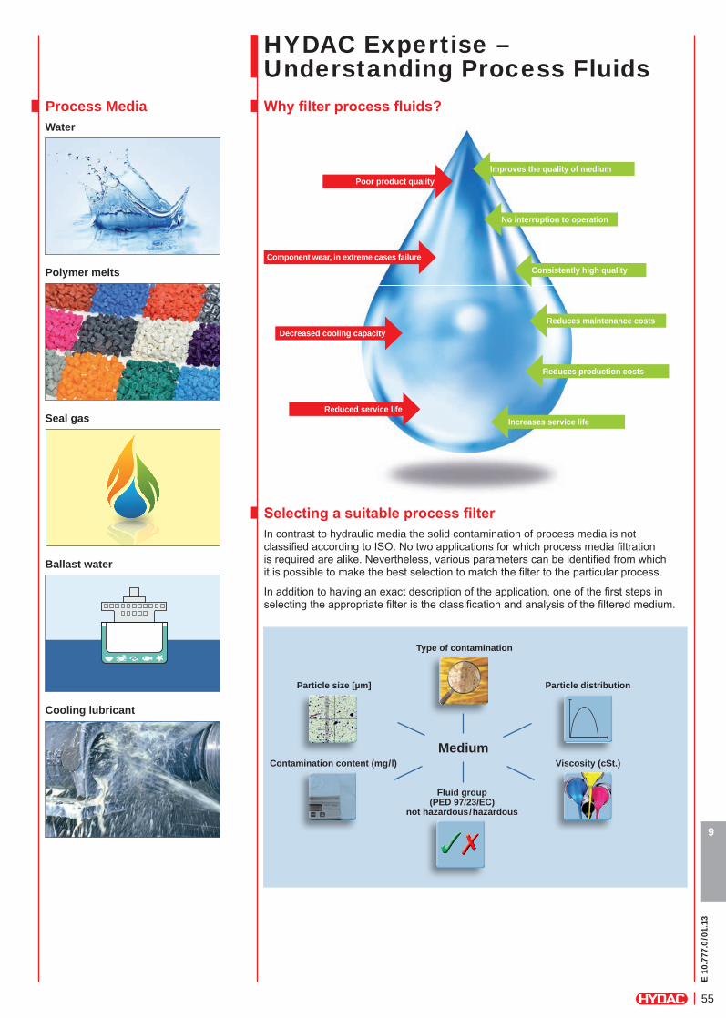
HYDAC Expertise –Understanding Process Fluids Whyfilterprocessfluids?Process Media
Water
SelectingasuitableprocessfilterIn contrast to hydraulic media the solid contamination of process media is not classifi ed according to ISO. No two applications for which process media fi ltration is required are alike. Nevertheless, various parameters can be identifi ed from which it is possible to make the best selection to match the fi lter to the particular process.
In addition to having an exact description of the application, one of the fi rst steps in selecting the appropriate fi lter is the classifi cation and analysis of the fi ltered medium.
Poor product qualityImproves the quality of medium
No interruption to operation
Consistently high quality
Reduces maintenance costs
Reduces production costs
Increases service life
Component wear, in extreme cases failure
Decreased cooling capacity
Reduced service life
Polymer melts
Seal gas
Ballast water
Type of contamination
Medium
Particle size [µm]
Fluid group(PED 97/23/EC)
not hazardous/hazardous
Contamination content (mg/l)
Particle distribution
Viscosity (cSt.)
Cooling lubricant
E 10
.777
.0/0
1.13
56
9
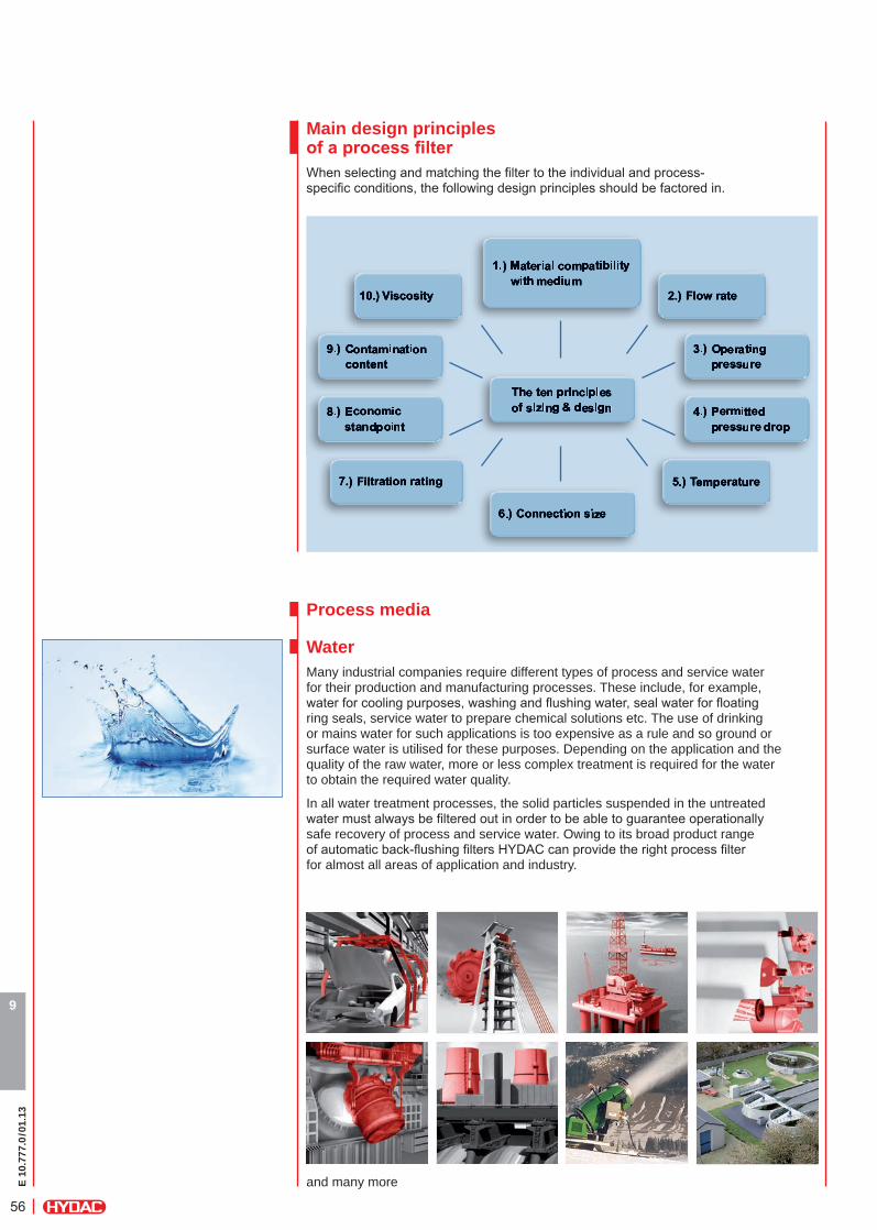
Main design principlesofaprocessfilterWhen selecting and matching the fi lter to the individual and process-specifi c conditions, the following design principles should be factored in.
WaterMany industrial companies require different types of process and service water for their production and manufacturing processes. These include, for example, water for cooling purposes, washing and fl ushing water, seal water for fl oating ring seals, service water to prepare chemical solutions etc. The use of drinking or mains water for such applications is too expensive as a rule and so ground or surface water is utilised for these purposes. Depending on the application and the quality of the raw water, more or less complex treatment is required for the water to obtain the required water quality.
In all water treatment processes, the solid particles suspended in the untreated water must always be fi ltered out in order to be able to guarantee operationally safe recovery of process and service water. Owing to its broad product range of automatic back-fl ushing fi lters HYDAC can provide the right process fi lter for almost all areas of application and industry.
and many more
Process media
E 10
.777
.0/0
1.13
57
9
Seal gasHYDAC gas fi lters have been specially developed for use in dry gas seals in turbo compressors.
Dry gas seals on turbo machines are very complex systems and extremely sensitive to contamination from solid particles, aerosols and condensates. Whilst the shaft is rotating, a tiny gap, just 3 μm wide, is formed at the seal ring, through which the seal gas fl ows. To protect these seals, the seal gases must be fi ltered accordingly to ensure the seal has as long a service life as possible.
Filter elements with a coalescing action (coalescer elements) are invariably used in all HYDAC seal gas fi lters. All the elements consist of a pleated fi lter material which defi nes the micron rating and the contamination retention capacity, and coalescer materials which cause the fl uid phase to coalesce.
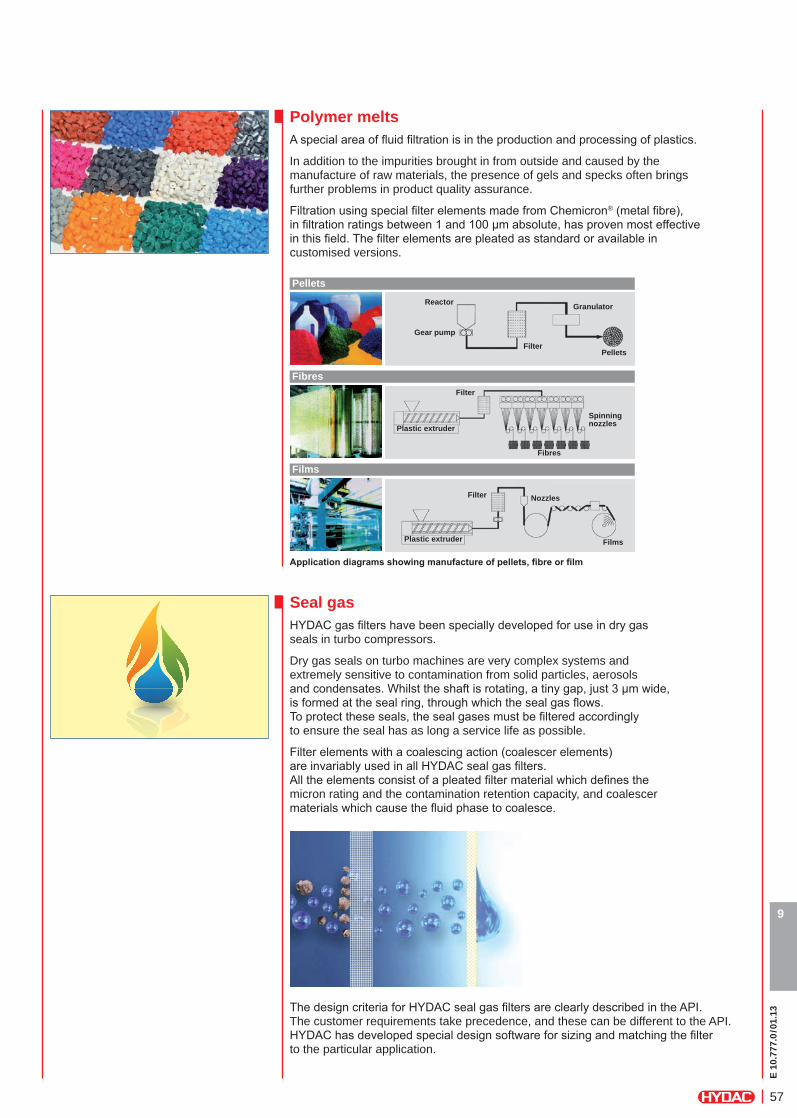
Polymer meltsA special area of fl uid fi ltration is in the production and processing of plastics.
In addition to the impurities brought in from outside and caused by the manufacture of raw materials, the presence of gels and specks often brings further problems in product quality assurance.
Filtration using special fi lter elements made from Chemicron® (metal fi bre), in fi ltration ratings between 1 and 100 µm absolute, has proven most effective in this fi eld. The fi lter elements are pleated as standard or available in customised versions.
Applicationdiagramsshowingmanufactureofpellets,fibreorfilm
Pellets
Fibres
Films
Gear pump
Plastic extruder
Plastic extruder
Spinning nozzles
Nozzles
Films
Fibres
Pellets
Reactor Granulator
Filter
Filter
Filter
The design criteria for HYDAC seal gas fi lters are clearly described in the API. The customer requirements take precedence, and these can be different to the API. HYDAC has developed special design software for sizing and matching the fi lter to the particular application.
E 10
.777
.0/0
1.13
58
9
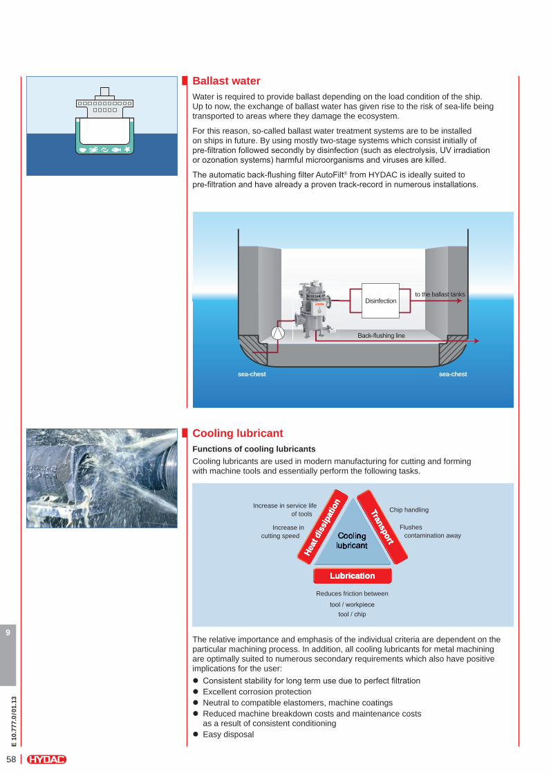
Ballast waterWater is required to provide ballast depending on the load condition of the ship.Up to now, the exchange of ballast water has given rise to the risk of sea-life being transported to areas where they damage the ecosystem.
For this reason, so-called ballast water treatment systems are to be installed on ships in future. By using mostly two-stage systems which consist initially of pre-fi ltration followed secondly by disinfection (such as electrolysis, UV irradiation or ozonation systems) harmful microorganisms and viruses are killed.
The automatic back-fl ushing fi lter AutoFilt® from HYDAC is ideally suited to pre-fi ltration and have already a proven track-record in numerous installations.
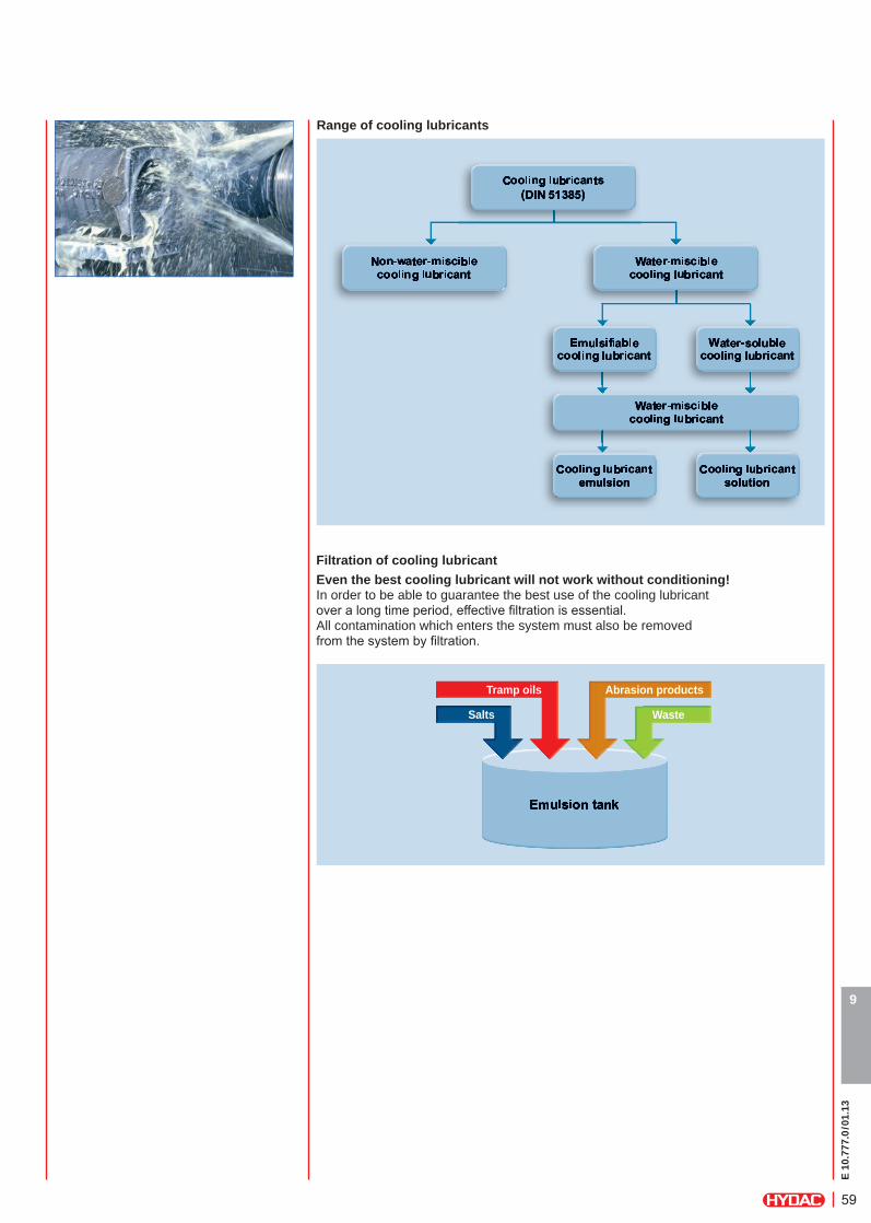
Cooling lubricant Functions of cooling lubricantsCooling lubricants are used in modern manufacturing for cutting and forming with machine tools and essentially perform the following tasks.
LubricationLubricationLubrication
Transport
Transport
Transport
Heat
dis
sipa
tion
Heat
dis
sipa
tion
Heat
dis
sipa
tion
The relative importance and emphasis of the individual criteria are dependent on the particular machining process. In addition, all cooling lubricants for metal machining are optimally suited to numerous secondary requirements which also have positive implications for the user:
z Consistent stability for long term use due to perfect fi ltration z Excellent corrosion protection z Neutral to compatible elastomers, machine coatings z Reduced machine breakdown costs and maintenance costs as a result of consistent conditioning
z Easy disposal
Increase in service life of tools
Flushes contamination away
Reduces friction between
tool / workpiecetool / chip
Disinfection
Back-fl ushing line
sea-chestsea-chest
to the ballast tanks
Chip handling
Increase in cutting speed
E 10
.777
.0/0
1.13
59
9
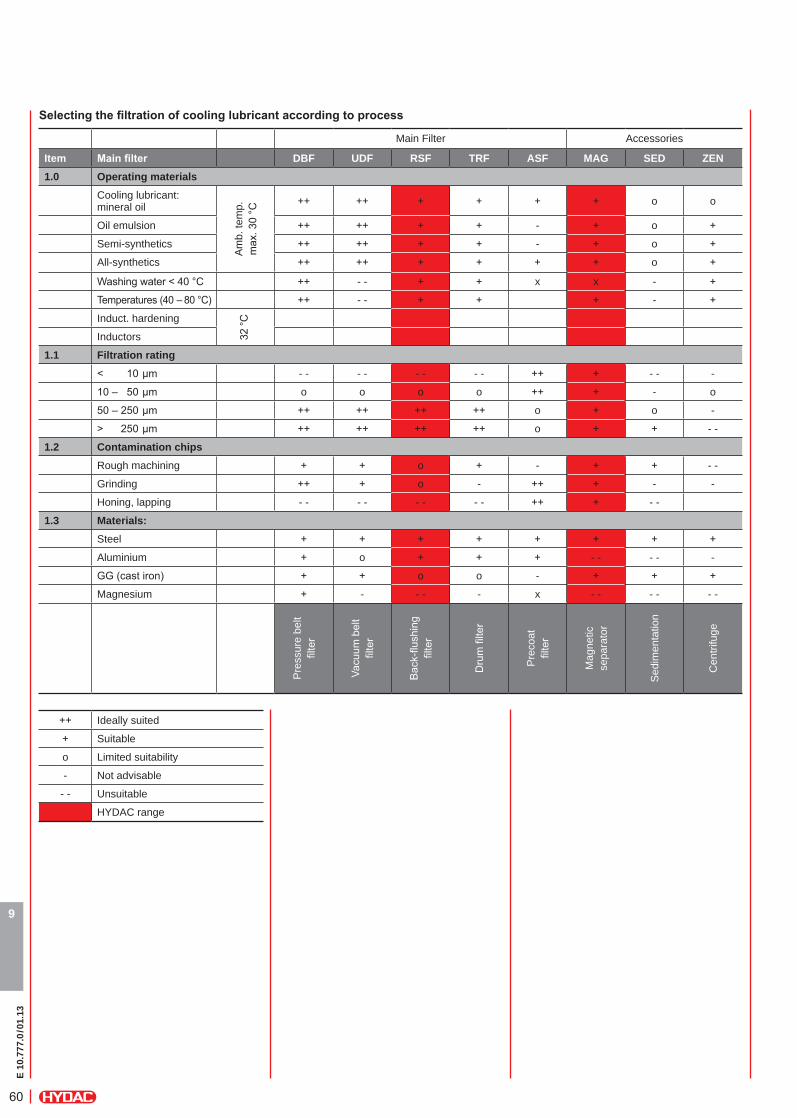
Range of cooling lubricants
Filtration of cooling lubricantEven the best cooling lubricant will not work without conditioning!In order to be able to guarantee the best use of the cooling lubricant over a long time period, effective fi ltration is essential.All contamination which enters the system must also be removed from the system by fi ltration.
Tramp oils Abrasion products
WasteSalts
E 10
.777
.0/0
1.13
60
9
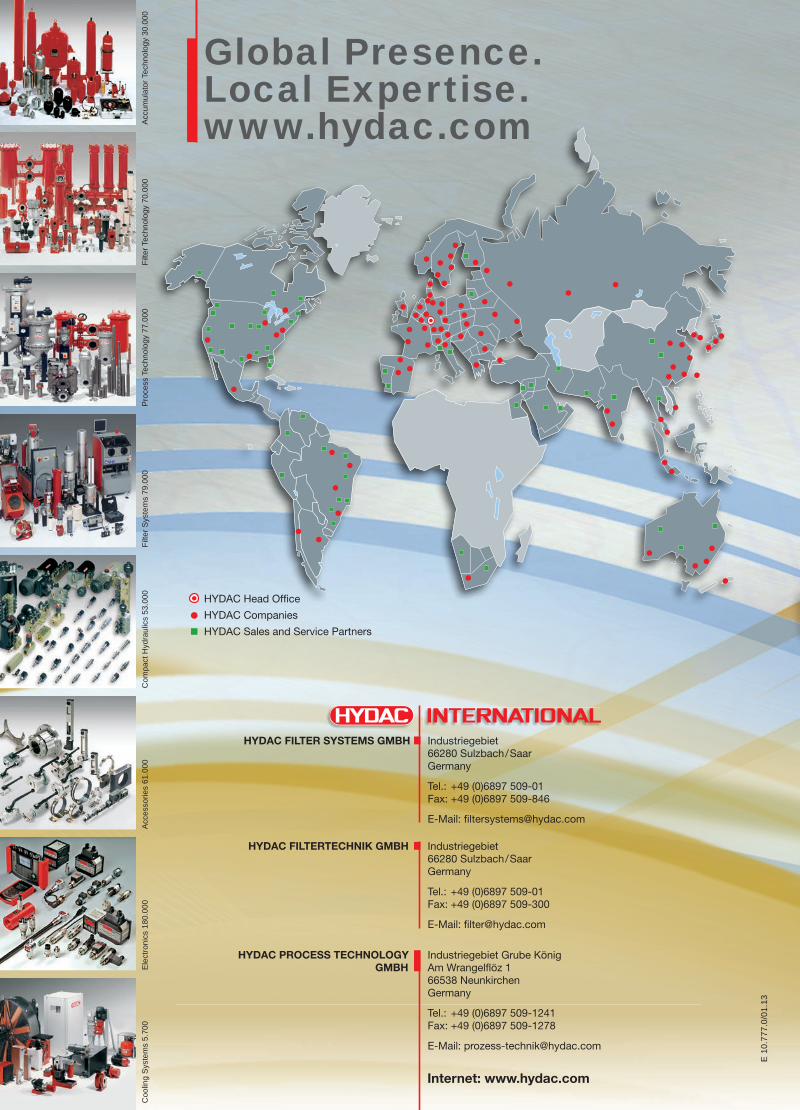
Selectingthefiltrationofcoolinglubricantaccordingtoprocess
Main Filter Accessories
Item Mainfilter DBF UDF RSF TRF ASF MAG SED ZEN1.0 Operating materials
Cooling lubricant: mineral oil
Am
b. te
mp.
m
ax. 3
0 °C
++ ++ + + + + o o
Oil emulsion ++ ++ + + - + o +
Semi-synthetics ++ ++ + + - + o +
All-synthetics ++ ++ + + + + o +
Washing water < 40 °C ++ - - + + x x - +
Temperatures (40 – 80 °C) ++ - - + + + - +
Induct. hardening
32 °C
Inductors
1.1 Filtration rating< 10 μm - - - - - - - - ++ + - - -
10 – 50 μm o o o o ++ + - o
50 – 250 μm ++ ++ ++ ++ o + o -
> 250 μm ++ ++ ++ ++ o + + - -
1.2 Contamination chipsRough machining + + o + - + + - -
Grinding ++ + o - ++ + - -
Honing, lapping - - - - - - - - ++ + - -
1.3 Materials:Steel + + + + + + + +
Aluminium + o + + + - - - - -
GG (cast iron) + + o o - + + +
Magnesium + - - - - x - - - - - -
Pre
ssur
e be
lt fil
ter
Vacu
um b
elt
filte
r
Bac
k-flu
shin
g fil
ter
Dru
m fi
lter
Pre
coat
fil
ter
Mag
netic
se
para
tor
Sed
imen
tatio
n
Cen
trifu
ge++ Ideally suited
+ Suitable
o Limited suitability
- Not advisable
- - Unsuitable
HYDAC range

E 10
.777
.0/0
1.13
61

E 10
.777
.0/0
1.13
62

E 10
.777
.0/0
1.13
63
Ele
ctro
nics
180
.000
Acc
esso
ries
61.0
00C
ompa
ct H
ydra
ulic
s 53
.000
Filte
r Sys
tem
s 79
.000
Pro
cess
Tec
hnol
ogy
77.0
00Fi
lter T
echn
olog
y 70
.000
Acc
umul
ator
Tec
hnol
ogy
30.0
00
Global Presence.Local Expertise.www.hydac.com
Industriegebiet 66280 Sulzbach/Saar Germany
Tel.: +49 (0)6897 509-01 Fax: +49 (0)6897 509-300
E-Mail: fi [email protected]
HYDAC FILTERTECHNIK GMBH
HYDAC Head Offi ce
HYDAC Companies
HYDAC Sales and Service Partners
Coo
ling
Sys
tem
s 5.
700
E 1
0.77
7.0/
01.1
3
E 1
0.77
7.0/
01.1
3
Filtration andFluid Conditioning.Product Overview.
Industriegebiet 66280 Sulzbach/Saar Germany
Tel.: +49 (0)6897 509-01 Fax: +49 (0)6897 509-846
E-Mail: fi [email protected]
Industriegebiet Grube König Am Wrangelfl öz 1 66538 Neunkirchen Germany
Tel.: +49 (0)6897 509-1241 Fax: +49 (0)6897 509-1278
E-Mail: [email protected]
HYDAC FILTER SYSTEMS GMBH
HYDAC PROCESS TECHNOLOGY GMBH
Internet: www.hydac.com
Fluid Condition Monitoring
Fluid Condition Monitoring
Fluid Condition Monitoring
Fluid Condition Monitoring
e_HYDAC_Gesamtfilterübersicht_Umschlag_EL_101212.indd 1-3 15.01.13 15:09:37