global overview of construction technology trends: energy...
TRANSCRIPT

Home"" """"> ar.cn.de.en.es.fr.id.it.ph.po.ru.sw
Global Overview of Construction Technology Trends: Energy
Efficiency in Construction (HABITAT, 1995, 210 p.)
(introduction...)
Foreword
1. Introduction and overview
2. Energy efficiency in the production of high-energy content
building materials
2.1. Cement
2.2. Lime
2.3. Clay bricks
2.4. Ceramic wall and floor tiles (2)
3. Innovative technologies related to the increased utilization of
low-energy building materials
3.1. Soil construction
3.2. Building stone, sand and aggregates
3.3. Low-cost binders
3.4. Timber and bamboo
4. Innovative technologies related to recycling of materials
(introduction...)
4.1. Organic wastes
4.2. Inorganic wastes
5. Energy conservation in construction
20/10/2011 meister10.htm
D:/cd3wddvd/NoExe/…/meister10.htm 1/213

5.1. Reducing transport energy5.2. Reducing on-site energy use
5.3. Labour-Intensive Methods
6. Energy efficient building design
6.1. Natural cooling of buildings (40)
6.2. Passive solar design
6.3. Passive solar heating of buildings (42)
7. Strategies for optimizing use of energy in construction and in
the production of building materials*
(introduction...)
7.1. Optimizing the designs of buildings
7.2. Improving energy efficiency in building-materials
production
7.3. Site-management of energy efficiency in construction
References
Annex
Solar timber seasoning in Sri Lanka**
Acknowledgement
Home"" """"> ar.cn.de.en.es.fr.id.it.ph.po.ru.sw
Global Overview of Construction Technology Trends: Energy
Efficiency in Construction (HABITAT, 1995, 210 p.)
(introduction...)
Foreword
20/10/2011 meister10.htm
D:/cd3wddvd/NoExe/…/meister10.htm 2/213
1. Introduction and overview2. Energy efficiency in the production of high-energy content
building materials
3. Innovative technologies related to the increased utilization of
low-energy building materials
4. Innovative technologies related to recycling of materials
5. Energy conservation in construction
6. Energy efficient building design
7. Strategies for optimizing use of energy in construction and in
the production of building materials*
References
Annex
Acknowledgement
UNITED NATIONS CENTRE FOR HUMAN SETTLEMENTS (Habitat)
Nairobi
The views expressed and the technical information and data given in this publication do
not necessarily reflect those of the United Nations. Mention of firm names and commercial
products does not imply the endorsement of UNCHS (Habitat).
The manuscript of this publication was produced in 1995. It is printed in 1997.
HS/376/95E
ISBN 92-1-131290-6
20/10/2011 meister10.htm
D:/cd3wddvd/NoExe/…/meister10.htm 3/213
Home"" """"> ar.cn.de.en.es.fr.id.it.ph.po.ru.sw
Global Overview of Construction Technology Trends: Energy
Efficiency in Construction (HABITAT, 1995, 210 p.)
(introduction...)
Foreword
1. Introduction and overview
2. Energy efficiency in the production of high-energy content
building materials
3. Innovative technologies related to the increased utilization of
low-energy building materials
4. Innovative technologies related to recycling of materials
5. Energy conservation in construction
6. Energy efficient building design
7. Strategies for optimizing use of energy in construction and in
the production of building materials*
References
Annex
Acknowledgement
References
1. UNCHS (Habitat), Energy for Building, HS/250/91E, Nairobi, 1991.
2. UNIDO/former CSSR Joint Programme, Overview of energy efficiency in the production
of building materials, Proceedings of the Expert Group Meeting on Energy Efficient
Building Materials for Low-cost Housing, ESCWA, Amman, Jordan, 1987.
20/10/2011 meister10.htm
D:/cd3wddvd/NoExe/…/meister10.htm 4/213

3. UNCHS (Habitat), Ibid, reference No. 1
4. UNIDO/former CSSR Joint Programme, Ibid, reference No. 2
5. Fog, M. H., and Nadkarni, K. L., Energy efficiency and fuel substitution in the cement
industry, World Bank, Washington, 1983.
6. Spence, R. J. S., Small-scale production of cementitous materials, IT publications Ltd.,
London, 1980.
7. UNCHS (Habitat), Small-scale production of Portland cement, HS/281/93E, Nairobi,
1993.
8. Spence, R. J. S., Alternative scales of production for cementatious materials,
Unpublished draft report prepared for the UNCHS (Habitat), 1988.
9. UNCHS (Habitat), Endogenous capacity-building for the production of binding materials
in the construction industry - selected case studies, HS/292/93E, Nairobi, 1993.
10. UNCHS (Habitat), Vertical-shaft lime-kiln technology, HS/303/93E, Nairobi, 1993.
11. Rai, M., Energy conservation in the development and production of building materials,
proceedings of the International Workshop on Energy Conservation in Building, April
1984, C.B.R.I., Roorkee, India.
12. UNCHS (Habitat), The economic and technical viability of various scales of building
materials production, HS/180/89E, Nairobi, 1989.
13. Gandhi, S., The brick industry in India: Energy use, tradition and development, Ph.D.
thesis, Cambridge University, United Kingdom, 1986,
20/10/2011 meister10.htm
D:/cd3wddvd/NoExe/…/meister10.htm 5/213

14. UNCHS (Habitat), Use energy by households and in construction and in production of
building materials, Report of the Executive Director to the Commission on Human
Settlements, 13th Session held in Harare, Zimbabwe, May 1991.
15. Mohamed K. F., Technology manual on claybricks in Pakistan, UNDP/UNIDO Regional
network in Asia and Pacific for low-cost building materials technologies and construction
systems, RENAS_BMTCS Manila, Philippines, 1988.
16. UNCHS (Habitat), Energy efficiency in housing construction and domestic use in
developing countries, HS/218/91E, Nairobi, 1991.
17. Sheriff, A., and Larji, B., Firing with waste oil and water, Ceramic monthly, vol. 30, No.
6.
18. UNCHS (Habitat), Soil construction as an energy-efficient material for low-cost
housing, paper presented to the Expert Group Meeting on Energy-efficient Building
Materials for Low-cost Housing, ESCWA, Amman, Jordan, November 1987.
19. UNCHS (Habitat), Earth construction primer, unpublished consultants report,
presented to the International Colloquem, Brussels, Belgium, 1984.
20. Intermediate Technology Development Group, ITDG, United Kingdom.
21. UNCHS (Habitat), Earth construction technology, HS/265/92/E, Nairobi, 1992.
22. UNCHS (Habitat), Journal of the network of African countries on local building material
and technologies, vol. 1, No. 4 and vol. 2, No. 2, ISSN 1012-9812, Nairobi, 1993.
23. UNCHS (Habitat), Ibid, reference No. 9.
24. UNCHS (Habitat), Journal of the network of African countries on local building material
20/10/2011 meister10.htm
D:/cd3wddvd/NoExe/…/meister10.htm 6/213

and technologies, vol. 2, No. 3, ISSN 1012-9812, Nairobi, 1993.
25. UNCHS (Habitat), A Compendium of information on selected low-cost building
materials, HS/137/88E, Nairobi, 1988.
26. Read, W.R., and others, A solar lumber kiln, Solar energy, Volume 15, London, The
United Kingdom.
27. Tschernitz, J.L., and Simpson, W.T., Solar heated forced air timber dryer for tropical
latitudes, Solar energy, vol. 22, London, The United Kingdom.
28. Rosen, H.N. and Chen, P.Y.S., Drying lumber in a kiln with external solar collectors.
29. Plumptr, R.A. and Jajanetti, D.L., Solar heated timber drying kilns, A manual on their
design and operation, TRADA, ODA, London, The United Kingdom, 1996
30. ESCAP, Building materials and construction technologies for low-cost housing in
developing ESCAP countries, Building technology series No. 9.
31. Stulz, R. and Mukerji, K., Appropriate building materials, A catalogue of potential
solutions, SKAT publications, 1988.
32. UNCHS (Habitat), Habitat news, vol. 12, No. 2 and vol. 14, No. 1.
33. Chopra, S.K., Cementitious binder from rice husk - an overview, Proceedings of the
seminar-workshop on rice-husk ash-cement, PICC, Manila, Philippines, 1982.
34. UNCHS (Habitat), Development of national technological capacity for environmentally-
sound construction, HS/293/93E, Nairobi, 1993.
35. ESCAP, Building materials and construction technologies for low-cost housing in
20/10/2011 meister10.htm
D:/cd3wddvd/NoExe/…/meister10.htm 7/213

developing ESCAP countries, Building technology series No. 12.
36. Government of India, Building Materials and Technology Promotion Council (MBTPC),
Standards and specifications for cost-effective and innovative building materials and
technologies.
37. Government of India, Central Fuel Research Institute (CFRI), Dhanbad, India.
38. Hodges, L., Environmental pollution (2nd edition), New York, Holt, Rinehart and
Winston, 1977.
39. UNCHS (Habitat), Ibid, reference No. 12.
40. UNCHS (Habitat), Technical Note No. 9.
41. Carter, C. and De Villiers, J., Principles of passive solar building design, Pergamon
Press, 1987.
42. UNCHS (Habitat), Technical Note No. 8
Home"" """"> ar.cn.de.en.es.fr.id.it.ph.po.ru.sw
Global Overview of Construction Technology Trends: Energy
Efficiency in Construction (HABITAT, 1995, 210 p.)
Annex
Solar timber seasoning in Sri Lanka**
20/10/2011 meister10.htm
D:/cd3wddvd/NoExe/…/meister10.htm 8/213

Global Overview of Construction Technology Trends: Energy Efficiency in Construction
(HABITAT, 1995, 210 p.)
Annex
Solar timber seasoning in Sri Lanka**
** This Annex is an edited and summarized version of an unpublished draft report
entitled: “Development of an Efficient Solar Kiln for Seasoning Structural Timber for
use in Building Trade”, and prepared by R. H. B. Exell, Professor, Division of Energy
Technology, Asian Institute of Technology (AIT), Bangkok, Thailand. This research
work was subcontracted to AIT by UNCHS (Habitat) for the National Building
Research Organization (NBRO), Sri Lanka.
Introduction
The Asian Institute of Technology (AIT) of Thailand on behalf of the National Building
Research Organization (NBRO) of Sri Lanka and supported by UNCHS (Habitat) undertook
20/10/2011 meister10.htm
D:/cd3wddvd/NoExe/…/meister10.htm 9/213
a research study on solar seasoning of secondary species of timber for use in the building
construction as a replacement to the primary species which are becoming scarce in the
market and are of high cost. The secondary species identified for promotion and suitable
for building construction (after taking into consideration strength, economy and
availability) are: Selinga, Alstonia, Ginisapu, Domba, Coconut and Rubber.
These species cannot be used immediately for structural purposes due to their high
moisture content. The cost of seasoning these timbers through conventional means, using
oil-fired kilns, is very high and renders these timbers uncompetitive in the building
market. It is for this reason that NBRO and AIT undertook this research project to design
and construct an efficient solar kiln for seasoning these secondary species of timber to
make them accessible to low-income house builders.
Earlier solar kilns in Sri Lanka
Prior to the start of the NBRO-AIT project, two types of solar kilns were existing in Sri
Lanka. The first type having capacities of 3.0 and 13.5 m of timber is in operation since
1983.
Both kilns have drying chambers made of concrete blocks, and the solar collectors are on
the ground to the south of the drying chambers. The collectors contain charcoal on the
floor to absorb solar radiation and are covered with glass. Air is circulated by means of
fans.
The collector of the 3 m3 kiln is 1,8 m wide by 7,2 m long whereas the 13.5 m3 capacity
kiln has a collector of 10.8 m wide by 15 m long the width of the collector being nearly
equal to the length of the wood stack inside the kiln. Many fans are used to control airflow
through somewhat complicated ducting. There is automatic control of the humidity by
means of vents to the outside air. A wood burner is used to supply supplementary heat at
20/10/2011 meister10.htm
D:/cd3wddvd/NoExe/…/meister10.htm 10/213

night and on cloudy days.
These solar kilns are well researched and engineered systems, however, because of their
high installation cost, they are not suitable for small business but a good option for the
larger companies. In contrast, the NBRO-AIT project was to develop a more economical
unit for the smaller users, and for this purpose, an improved greenhouse type solar kiln
(described next) seemed to be the best.
The second type of kiln introduced into Sri Lanka was designed like a portable greenhouse
having an aluminium frame covered with clear plastic sheet. It was developed by the
Intermediate Technology Group (ITDG) United Kingdom, and was installed at the Wood
Technology Section of the State Timber Corporation at Kaldemulla (1). The kiln is in two
halves clamped together, the front half housing the fan motors and switchgear for air
circulation, and the back half covering the timber stack. Both halves have lifting handles
and can easily be moved by, as few as, four people and placed around an air dried timber
stack on any level site. This avoids having to move the stack, which is a long and laborious
job without heavy equipment.
The new project
Local investigation revealed that the target group of users for the proposed solar-timber
kiln would be small sawmills in urban areas rather than the very small cottage or large-
scale industries. Seasoning would be mainly for secondary species of timber for building
construction (not primary species, and not timber for furniture making) and the two main
species would be rubber and coconut wood.
The capacity of the kiln would be about 7 m3 of timber. It would be designed to
accommodate planks of coconut wood, which are longer than usual (up to 5 m). The
design would be such that the kiln is portable and could be erected around stacks of
20/10/2011 meister10.htm
D:/cd3wddvd/NoExe/…/meister10.htm 11/213

timber that have been built in advance. These stacks of timber would be air-dried initially,
and would then be dried in the solar kiln. The air inside the solar kiln would be moved by
means of fans since it would be assumed that the users would have electric power
available. If the drying period proved to be too long, the addition of an auxiliary wood-
burning heater would be considered.
Design and construction of the kiln
The basic design concept is shown in figure 1. The stack of timber is supported 0.6 m
above the floor of the kiln on a 3 × 6 array of brick pillars 0.9 m and apart. The stack is
built up with the support of crossbearers at the bottom-stickers between the layers of
planks.
The height of the stack is 1.2 m making the height of the kiln 1.8 m above the floor.
The floor of the kiln is made of brick and cement, and is slightly convex so that any rain
that may leak through the cover of the kiln does not remain in puddles. The floor extends
from below the wood stack out to a distance slightly more than 5.4 m from the front of the
stack. It is painted with bituminous paint, so that, besides being waterproof to prevent
moisture entering the kiln from the ground below, its black colour absorbs solar radiation.
20/10/2011 meister10.htm
D:/cd3wddvd/NoExe/…/meister10.htm 12/213

Figure 1. The basic design concept of kiln
The wood stack is protected from direct solar radiation by a cover of aluminium sheet and
the black floor serving as solar collector is covered by clear plastic sheet (of a type that
can withstand deterioration by ultraviolet solar radiation) supported by an aluminium
frame. The frame is in three sections: I at the end of the solar collector; II in the middle;
and III over the wood stack.
The air is circulated inside the kiln by means of fans built into section II of the frame.
20/10/2011 meister10.htm
D:/cd3wddvd/NoExe/…/meister10.htm 13/213

After being blown from the solar collector through the wood stack by the fans, the air
returns via an airspace behind the wood stack and the space under the stack. Clear plastic
sheet stretched horizontally inside the kiln from the bottom of the wood stack to the
centre of the solar collector separates the return air from the solar heated air passing
through the fans. There is no airspace between the ends of the stack and the sides of the
kiln.
Air vents, which can be opened and closed by varying amounts, are provided at the end of
the solar collector and behind the wood stack for humidity control inside the kiln.
Provision is made for building two identical wood stacks side-by-side, and the total brick
and cement floor area is double that required for a single solar kiln. With this arrangement
it is possible to have one stack being air-dried while the other is being solar-dried. When
the solar drying is finished, the frame and plastic sheet coverings that form the solar kiln
are dismantled and re-erected over the air-drying stack. The solar-dried timber is then
taken away for use, and another stack is built in its place to be air-dried. Thus, a
succession of wood stacks can be seasoned, each passing through an air-drying stage
followed by a solar drying stage.
Performance calculations
The following calculations which are not fully precise because of uncertainties regarding
the actual drying process of rubber wood are made to establish the duration of drying and
the amount air flow required. Different samples of wood-cut to a variety of sizes are
expected to have different drying properties. Other species of wood will also behave in a
variety of ways. The principles of the calculations are based on studies by Eckelman and
Baker (2) and Exell (3).
An estimate of the expected drying time may be made as follows assuming that:
20/10/2011 meister10.htm
D:/cd3wddvd/NoExe/…/meister10.htm 14/213

(i) the kiln capacity is 7.1 m3;
(ii) the density of the undried wood is 680 kg/m3;
(iii) the change in moisture content (dry basis) is 40 to 12 per cent;
(iv) the air temperature change in the kiln is 27° to 42°C; and
(v) the mean daily solar radiation is 15.3 MJ/m3.
Then one finds that:
(i) the mass of wet wood in the kiln is 4800 kg;
(ii) the mass of water to be removed is 960 kg; and
(iii) the heat energy required to vaporize the water is 2760 MJ.
The collector area is 26 m2. If the efficiency of the collector is 40 per cent (an optimistic
figure) the solar-heat energy available per day on the average is 160 MJ, and so it will
take about 17 days to dry the timber.
The estimation of the airflow required is as follows:
Assuming an ambient air temperature of 27°C, and ambient air humidity 77 per cent, and
assuming the air is heated in the kiln to 42°C, one finds from the psychometric chart that
the moisture carrying capacity of the air is 6.2 × 10⁻³ kg of water per kg of dry air.
Therefore, the volume of air required for drying is 1.5 × 10” m. If the drying is to be done
in 14 days, working 10 hours per day, the flow rate would be 18 m3/min.
The smallest fans available were 30 cm in diameter and with a power of 35 W and a flow
rate of 5 m3/min. Three such fans were used in the design to give surplus air flow and to
overcome the resistance of the stack. The fans can be kept running in the evening to
utilize the heat stored in the floor of the collector and the wood stack, and provide extra
20/10/2011 meister10.htm
D:/cd3wddvd/NoExe/…/meister10.htm 15/213

drying after sunset.
Summary of experimental results
Table 1 shows the results obtained in five separate test runs of the solar seasoning kiln.
The first test run was done during a wet period when rain and cloud hindered the drying of
the timber; 38 days were required to dry rubber wood from the exceptionally high
moisture content of 70 per cent down to 11 per cent. This long drying time is inevitable at
certain times of the year. The other test runs show that the performance of the kiln is
satisfactory when the weather is favourable; at such times it takes about two weeks to dry
timber that is one inch thick from moisture content about 40 per cent to about 14 per cent.
Table 1. Experimental results from NBRO-AIT kiln in Sri Lanka
Species Rubber Mahogany Coconut Ginisapu Albezia
Thickness (cm) 3,8 2,5 5.0 2,5 1,9
Initial m.c. (percentage) 70 45 34 40 40
Final m.c. (percentage) 11 14 13 9 11
Wet days 13 - - - -
Clear days 25 16 18 14 12
Proposed modifications in the design
Various tests carried out on the prototype kiln revealed that a number of modifications in
the design should be made in future kilns in order to improve its performance of this type.
These modifications are detailed as follows:
Experience has shown that better drying is obtained if 5 × 5 cm stickers are used instead
20/10/2011 meister10.htm
D:/cd3wddvd/NoExe/…/meister10.htm 16/213

of 2.5 × 2.5 cm stickers which would reduce the resistance to air flow. Obviously, this
would reduce the volume of timber stack in the kiln. Therefore, an enlargement of the
space for the wood stack should be considered in future.
Figure 2 shows an outline how the structure could be improved. It is envisaged that future
kilns should be fixed permanently in position (although it should be possible to dismantle
them and transport them from one site to another). Therefore, the brick and cement floor
need to be large enough for only one collector and stack instead of two as in the present
design. This is because it was found unnecessary to carry out predrying in the open air in
some cases, and even when open air predrying was done it was considered easier to
transfer the wood from one stack to the other using unskilled labour than to move the kiln
itself (with increased risk of damage). It takes four unskilled labour a day (4 hours) to
move one full stack of timber, i.e. 4 more days to unload and reload the kiln.
Figure 2. Proposed new structure. Fans are fixed to section I which are removable
It will be noted that the proposed new structure is in four sections instead of two for ease
of construction. Section I at the front of the solar collector is shorter than in the existing
20/10/2011 meister10.htm
D:/cd3wddvd/NoExe/…/meister10.htm 17/213

design; it appears that there is little flow through the narrow part of this section so it
could be eliminated without much loss in performance of the system. This section should
also be made easily removable to facilitate maintenance of the fans. The fans are further
away from the wood stack in order to improve the uniformity of air distribution through
the stack, and also to simplify the mounting of the fans. There could also be an optional
addition of two more fans, making a total of five, to increase the airflow. These fans
should be shaded from the direct rays of the sun by means of opaque covers in the roof of
the collector just above the fans in order to avoid overheating in bright sunlight. This will
lengthen the life of the fans.
It is suggested that, the compartment behind the wood stack should be enlarged to a
width of 90 cm to improve the airflow, and also to make it easier for personnel to enter
the kiln for inspection of the wood. The floor of this compartment might be painted black
to obtain a little more absorption of solar energy.
In stormy weather the plastic sheet on the top of the collector may flap about vigorously.
To alleviate this problem, bars should be fixed to the frame over the plastic sheet to hold
the sheet down.
Finally, the feasibility of adding an auxiliary heating system to give better drying in cloudy
weather and at night should be considered. During the present tests there was a period of
16 days without sunshine, therefore, auxiliary heating might have been useful at this time.
Figure 3 shows how this could be done at a relatively low cost. Air-ducts are run between
the pillars supporting the wood stack. At the entrance to the ducts tins containing
sawdust, rice husks or some other locally-available combustible-waste material supply hot
air when the fuel is burned.
20/10/2011 meister10.htm
D:/cd3wddvd/NoExe/…/meister10.htm 18/213

Figure 3. Idea for auxiliary heating system
At the other end, a small fan draws the heat through the ducts. The main fans in the kiln
are used to circulate the air heated by the ducts through the wood stack.
There appear to be no difficulties in introducing such an auxiliary heating system beyond
the obvious one of securing a supply of fuel. The design calculations to be done would
include sizing of the fuel-burning stoves, the sizing of the ducts, and the choice of a
suitable fan.
Test and results
For all except one test, a full stack of timber was loaded into the kiln. One inch thick
20/10/2011 meister10.htm
D:/cd3wddvd/NoExe/…/meister10.htm 19/213

stickers were used to separate layers of planks for Rubber, Mahogany and Coconut wood
and two inch ones were used in the case of Ginisapu and Albezia. The exception to the full
stack was Mahogany, where only 1.60 m3 of timber were available instead of the usual 6
to 7 m. sampling was done in the following manner (see figure 4). Sample planks from the
front upper, rear upper, middle, front lower and rear lower parts of the stack were
selected, as shown in the figure. A section of each selected plank 90 cm long was cut out
as sample and was weighed periodically during the testing period to determine the
changes of moisture content with time. Small pieces of 2.5 cm long at the ends of the
sample were taken out and weighed to find the initial moisture content of the wood at the
beginning of the test run. They were first weighed wet. Then they were dried in an oven at
temperatures 100 to 105°C for 2 hours, kept for another 4 hours, and finally weighed
again to determine the dry weight. Moisture contents in this report are expressed on the
dry basis (weight of water in the wood divided by the weight of oven dried wood). The
ends of the 90 cm long samples were painted to prevent drying through the ends (and also
to reduce end-splitting).
20/10/2011 meister10.htm
D:/cd3wddvd/NoExe/…/meister10.htm 20/213

Figure 4. Sample diagram. Upper diagram, is a cross section of stack showing positions of
samples. Lower diagram is a method of cutting sample plank. Pieces A and B are oven
dried to find initial moisture content. Kiln sample is weighed periodically to find change of
moisture content with time.
The wet and dry-bulb temperatures within the kiln and outside in the ambient air were
recorded. It was found that the ambient conditions were rather constant with time, while
inside the kiln the conditions varied due to changes in the weather. The temperature of the
air emerging from the stack was typically 5° to 10°C cooler than the air entering the stack
from the solar collector. This was due to the cooling effect of the evaporation of the water
from the wood, and also due to the fact that the area of the stack was shaded from
sunlight. Typical temperatures and humidities observed are shown in table 2.
20/10/2011 meister10.htm
D:/cd3wddvd/NoExe/…/meister10.htm 21/213

Table 2. Typical temperatures and humidities observed
Dry bulb Wet bulb Depression Rel. Hum.
(percentage)
Ambient (C°) 32 28 4 70
Collector (C°) 40-50 30-40 7 50
Table 3 shows the results obtained in five experimental runs. Except in the case of the test
using rubber wood, which was done during a period of very wet weather, it took about
two weeks to dry timber from about 40 per cent moisture content to 14 per cent moisture
content in this solar kiln.
Table 3. Experimental results on moisture contents of different types of wood at
Dankotuwa
Type of
wood
Stage Moisture content (MC)
(Percentage)
Remarks
FU FL MID RU RL AVG
Rubber, V:
6.75
Initial 72 67 82 59 69 70 Planks of 3.75 cm thickness
CD: 25 Final 7.8 8.3 13.5 12.4 13.5 11
WD: 13 Drop 64.2 58.7 68.5 46.6 55.5 59
Mahagoni,
V:1.6
Initial 54.0 36.0 45 Planks of 2.5 cm thickness
CD: 16 Final 13.7 13.8 14
WD: 0 Drop 40.3 22.2 31
Coconut, V: Initial 43.0 20.0 44.0 41.0 23.0 34 Rafters 5.0 × 7.5 cm
20/10/2011 meister10.htm
D:/cd3wddvd/NoExe/…/meister10.htm 22/213

Coconut, V:
5.4
Initial 43.0 20.0 44.0 41.0 23.0 34 Rafters 5.0 × 7.5 cm
CD: 18 Final 12.1 11.9 13.6 13.3 12.5 13
VD: 0 Drop 30.9 8.1 30.4 27.7 10.5 21
Ginisapu, V:
FK
Initial 30.7 34.5 54.2 30.0 50.4 40 Planks of 2.5 cm thickness with 2.5 cm
stickers
CD: 14 Final 13.8 5.6 1.6 11.3 12.6 9
WD: 0 Drop 16.9 28.9 52.6 18.7 37.8 31
Albezia, V: FK Initial 43.8 34.0 36.0 35.0 53.0 40 Planks of 1.9 cm thickness with 5 cm
stickers
CD: 12 Final 12.0 3.0 10.0 10.0 17.0 11
D: 0 Drop 31.8 31.0 26.0 25.0 36.0 29
Note:
CD means clear days
WD means wet days
V means volume in m3
FK means full kiln
FU, FL, MID, RU and RL mean front upper, front lower, middle, rear upper, rear
lower of the stack respectively (refer to figure 4)
Use of the vents and fans
During some of the test runs it was observed that some water was condensed on the
inside of the plastic sheet at night. This water must come either from the moisture in the
air or from the moisture in the timber. If it is from the air, then closing the vents at night
can ensure that no moisture is added to the interior of the kiln at night and there is no
20/10/2011 meister10.htm
D:/cd3wddvd/NoExe/…/meister10.htm 23/213

gain or loss in the performance. If it is originated from the timber, then gain has been
made by utilizing the temperature difference between the warm-wood stack and the cold-
plastic sheet (cooled by longwave radiation at night) which removes further moisture
from the wood.
The procedure adopted to meet this circumstance is to close the vents at night, and leave
them fully open during the day to allow the condensed moisture to escape. Although it
may take some time for the condensation on the plastic sheet to disappear, the decision of
having the vents fully open from 8 a.m. to 5 p.m. was found to be satisfactory.
The fans are used all day. There is a question as to whether they should be used at night.
If they are, there could be more drying (due to the condensation on the cooler plastic
sheet as observed above), but the main advantage might be the securing of more uniform
drying throughout the wood stack. On the other hand continuous operation of the fans will
shorten their life. Therefore, it seems better to turn them off at night and have them, fully
on during the day.
In summary it is recommended that:
(a) during the day the vents should be open and the fans should be on; and
(b) at night the vents should be closed and the fans should be off.
Air flow in the kiln
A special experiment was performed to map out the air flow inside the kiln. Light pieces of
thread were suspended at many points inside the kiln: small currents of air were able to
deflect the thread and show the direction of flow. The experiment was entirely qualitative
because no instrument for measuring the air velocity was used. Instead the observed flow
was simply classified as zero, light or strong. The currents were noted on the empty kiln
and in the kiln with a full stack of timber, with and without the fans running, and with and
20/10/2011 meister10.htm
D:/cd3wddvd/NoExe/…/meister10.htm 24/213

without the vents open.
The results are shown in figures 5, 6, 7 and 8.
Figure 5. Kiln empty. Fans off. All airflows light
20/10/2011 meister10.htm
D:/cd3wddvd/NoExe/…/meister10.htm 25/213
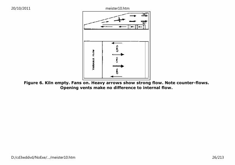
Figure 6. Kiln empty. Fans on. Heavy arrows show strong flow. Note counter-flows.
Opening vents make no difference to internal flow.
20/10/2011 meister10.htm
D:/cd3wddvd/NoExe/…/meister10.htm 26/213
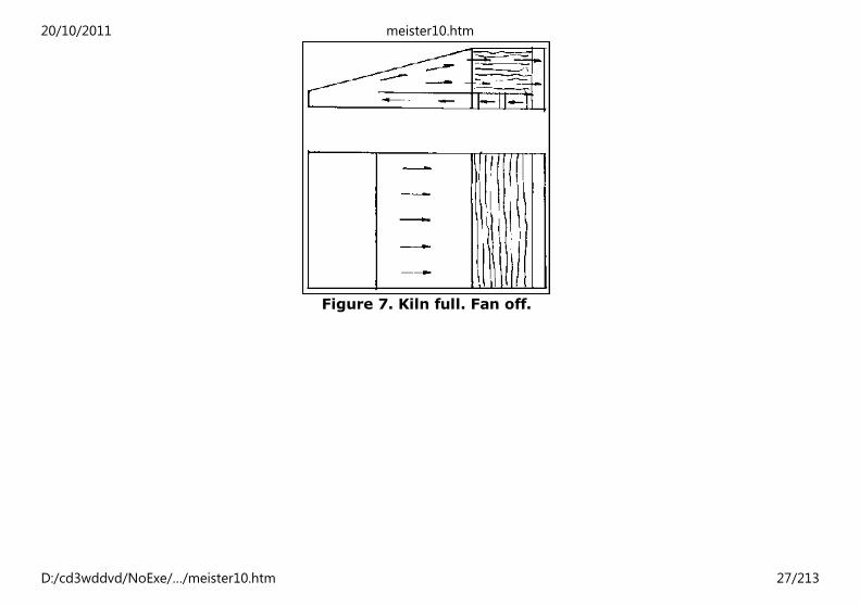
Figure 7. Kiln full. Fan off.
20/10/2011 meister10.htm
D:/cd3wddvd/NoExe/…/meister10.htm 27/213

Figure 8. Kiln full. Fans on. Circulation of counter current fans and near wood stack
It can be seen that when the fans are off there is a natural circulation of air in the proper
direction produced by free convection. This confirms expectations during the design stage,
and ensures that electrical energy is not wasted in making the fans force the air against
the natural flow. The observations also show that when the fans are running, there is a
counterflow (against the proper direction) at the sides of the large space containing the
fans, and also in the top and bottom of the wood stack itself.
The counterflow in the space containing the fans may be eliminated by filling in the panel
holding the fans with plastic sheet so that the counterflow is locked. The counterflow in
the wood stack appears to occur because the fans are too close to the stack and fail to
give a uniformly distributed current of air through the stack. This could be corrected in
future designs by positioning the fans farther away from the stack as proposed earlier
(see figure 2).
20/10/2011 meister10.htm
D:/cd3wddvd/NoExe/…/meister10.htm 28/213

The opening and closing the vents seems not to have a significant effect of the flow inside
the kiln. The flow through the front vent is always inwards, while that through the rear
vent is indefinite. Undoubtedly, the wind outside the kiln has an effect on the flow through
the vents.
The random motion of air in the narrow front end of the solar collector suggests that this
part of the structure does not heat the air very effectively, in all probability little would be
lost if the sides of this section were reduced (see figure 2).
Note:
For more detailed treatment of solar timber seasoning refer to “Solar Heated
Timber Drying Kiln. A manual on their design and operations” 1996. ISBN 1
900510006 by R. A. Plumptre and D. L. Jayanetti. Published by TRADA Technology
Ltd for the Overseas Development Administration (ODA), The United Kingdom.
Reference
The Nomad Solar Kiln, manufactured by the Cambridge Glasshouse Company Ltd, United
Kingdom.
Eckerman, C.A., and Baker, J.L., Heat and air requirements in the kiln drying of wood,
Research Bulletin No. 933. Perdue University, Indiana, The United States of America, 1976.
Exell, R.H.B., Basic design theory for a simple solar rice dryer. Renewable energy review
journal, vol. 1, No. 2, 1980.
Home"" """"> ar.cn.de.en.es.fr.id.it.ph.po.ru.sw
20/10/2011 meister10.htm
D:/cd3wddvd/NoExe/…/meister10.htm 29/213

Global Overview of Construction Technology Trends: Energy
Efficiency in Construction (HABITAT, 1995, 210 p.)
(introduction...)
Foreword
1. Introduction and overview
2. Energy efficiency in the production of high-energy content
building materials
3. Innovative technologies related to the increased utilization of
low-energy building materials
4. Innovative technologies related to recycling of materials
5. Energy conservation in construction
6. Energy efficient building design
7. Strategies for optimizing use of energy in construction and in
the production of building materials*
References
Annex
Acknowledgement
Acknowledgement
The author wishes to acknowledge with thanks the excellent support given to him by his
colleagues: Ms. Jane Kimata for typing the manualscript and Ms. Rani Dogra for laying out
and producing the camera-ready copy.
UNITED NATIONS CENTRE FOR HUMAN SETTLEMENTS (Habitat)
P.O. Box 30030, Nairobi, KENYA. Telephone: 621234
Cable: UNHABITAT; Fax: (254)-2-624266/624267; Telex: 22996 UNHAB KE
20/10/2011 meister10.htm
D:/cd3wddvd/NoExe/…/meister10.htm 30/213

Home"" """"> ar.cn.de.en.es.fr.id.it.ph.po.ru.sw
Global Overview of Construction Technology Trends: Energy
Efficiency in Construction (HABITAT, 1995, 210 p.)
(introduction...)
Foreword
1. Introduction and overview
2. Energy efficiency in the production of high-energy content
building materials
3. Innovative technologies related to the increased utilization of
low-energy building materials
4. Innovative technologies related to recycling of materials
5. Energy conservation in construction
6. Energy efficient building design
7. Strategies for optimizing use of energy in construction and in
the production of building materials*
References
Annex
Acknowledgement
Foreword
In the closing decade of this century, as the world strives for a better quality of life,
20/10/2011 meister10.htm
D:/cd3wddvd/NoExe/…/meister10.htm 31/213

millions of poor are fighting for life itself. Already more than 600 million people in cities
and towns throughout the world are homeless or live in dilapidated houses. Unless a
revolution takes place in solving the shelter problem, this shocking statistic will triple by
the year 2025. Providing decent shelter for this huge number of people will no doubt be
the major challenge of the construction sector well into the next century.
Traditionally, technological development in the construction sector has always influenced
social and economic development, including human settlements development.
Technological advancement has contributed to the higher productivity and lower cost of
construction and has even reduced the adverse effects of construction on the environment
in some countries. But the benefits of technology has yet to be fully harnessed by
developing countries to enable them meet the increasing demand of shelter for their low-
income population.
As part of its efforts in addressing the problems of shelter delivery in developing
countries, the United Nations Centre for Human Settlements (Habitat), over the past
decade or so, has been promoting the development of appropriate, energy-efficient and
environmentally-sound construction technologies which rely, mainly, on locally-available
resources. The establishment of the “Network of African Countries on Local Building
Materials and Technologies”, a decade ago, which has the objective of strengthening local
technological capacity through information flow, regional cooperation and technology
transfer is an example of the Centre’s activities in this important sector.
Recognizing the importance of the construction sector in improving the shelter condition
of millions of low-income population, a distinct section on construction has been included
in the Habitat Agenda adopted by the Second United Nations Conference on Human
Settlements (Habitat II). The Agenda, among other things, emphasizes the need for
increased use of energy-efficient and environmentally-sound technologies in construction
so as to ensure its sustainability. The present publication, in line with the
20/10/2011 meister10.htm
D:/cd3wddvd/NoExe/…/meister10.htm 32/213

recommendations of the Habitat Agenda, attempts to bring together recent advances in
construction technology which are suited to low-cost construction using locally-available
resources. Particular emphasis has been given in this publication to energy efficient and
cleaner technologies and recycling for the production of basic building materials and
components. In view of the importance of architectural design in reducing the energy
requirements in buildings, selected energy efficient building design concepts have also
been incorporated.
This publication represents another significant step in the continuing efforts of the Centre
to contribute to the improved performance of the construction sector in developing
countries. It is hoped that both policy-makers and professionals will find the contents of
this document interesting and useful in their work and that the “strategies for optimizing
the use of energy in construction” outlined in the last chapter of this publication, will help
national and local decision-makers and managers in their efforts to improve human
settlement conditions in their countries.
The efforts of Mr. Baris Der-Petrossian of the Research and Development Division in
conducting in-house research and preparing this document are thankfully acknowledged.
Dr. Wally N’Dow
Assistant Secretary-General
UNCHS (Habitat)
Home"" """"> ar.cn.de.en.es.fr.id.it.ph.po.ru.sw
Global Overview of Construction Technology Trends: Energy
20/10/2011 meister10.htm
D:/cd3wddvd/NoExe/…/meister10.htm 33/213

Efficiency in Construction (HABITAT, 1995, 210 p.)
(introduction...)
Foreword
1. Introduction and overview
2. Energy efficiency in the production of high-energy content
building materials
3. Innovative technologies related to the increased utilization of
low-energy building materials
4. Innovative technologies related to recycling of materials
5. Energy conservation in construction
6. Energy efficient building design
7. Strategies for optimizing use of energy in construction and in
the production of building materials*
References
Annex
Acknowledgement
1. Introduction and overview
Several studies have revealed that, during the periods of national economic growth,
construction activity grows at a faster rate than the economy as a whole. In many
developing countries, the basic indicators of underdevelopment are related to gross
inadequacies in shelter, infrastructure and amenity delivery systems which result from the
constraints of the construction sector. Thus, the construction industry can be said to be
the backbone of national economic and social development.
Despite the strategic importance of the construction sector, it still operates with major
20/10/2011 meister10.htm
D:/cd3wddvd/NoExe/…/meister10.htm 34/213

inadequacies in many countries. For example, construction costs are relatively high, basic
inputs, particularly building materials, are scarce and expensive, the sector is import
dependent amidst availability of unexploited indigenous resources. In short, the
construction sector’s outputs do not fulfil the demands for shelter and infrastructure
especially the demands of low-income population.
There are several reasons for this anomaly but the most fundamental ones are: lack of
sound planning and policies; lack of finance; and use of inappropriate and outdated
technologies which are not suitable for local conditions, and are wasteful in terms of
energy inputs. This publication addresses some of the latter problems.
The rapid pace of technological changes in the past couple of decades has radically
impacted the nature of construction practices in developed countries and this has brought
the technology-related issues in the forefront in various sectors including the building
materials industries. Changing technological needs of the construction sector necessitates
that the developing countries rectify their past deficiencies and enhance capacities to
enable them to face the new challenges. Regardless of its level of development, each
developing country should possess such capacities as to be able to monitor and assess the
implications of the advances taking place around the world. It should further ensure that,
the domestic construction sector is able to respond positively to changing technological
environment.
In this context, absorption and adoption of “innovative” and “appropriate” technologies
for developing human settlements in general, and for improving the construction sector in
particular, play a vital role in any programme related to social and economic development.
Adoption of “innovative” and “appropriate” technologies is not limited to setting up a
mechanism to react to the above mentioned changes but also comprises the continuous
acquisition of new information on construction processes in order to induct innovations.
20/10/2011 meister10.htm
D:/cd3wddvd/NoExe/…/meister10.htm 35/213
No doubt information on available technological options is an important input for
improving the performance of the construction industry, but final diffusion of technology
goes beyond it and takes care of technological know-how, sources of technologies and
finally establishes a mechanism and a framework for the modernization of existing
industries.
The importance of the construction sector was recognized at HABITAT: United Nations
Conference on Human Settlements, held in Vancouver, Canada in 1976 and the Commission
on Human Settlements in its fifteen sessions over the past twenty years has underscored
the significance of the sector by adopting special resolutions and by recommending
selected programme areas to be implemented by UNCHS (Habitat). Owing to the vital role
of the indigenous construction sector in the achievement of national economic and social
goals, most of the activities of the Centre, in the construction sector, have focused on
strengthening the domestic capacities of developing countries to enable them to meet the
increasing demand of the construction sector outputs-housing and infrastructure facilities.
Agenda 21, adopted by the United Nations Conference on Environment and Development
(UNCED), held in Rio de Janeiro, Brazil, in June 1992, has underscored the direct
relationship between sustainable human settlements development and the sustainable
construction-sector activities. In so doing, it has included a separate programme area
entitled “Promoting sustainable construction industry activities” in its recommendations
on “Promoting sustainable human settlements” (Chapter 7 of Agenda 21).
The basis for action for promoting sustainable construction activities as stated in Agenda
21 reads as follows:
“The activities of the construction sector are vital to the achievement of the
national socio-economic development goals of providing shelter, infrastructure and
employment. However, they can be a major source of environmental damage
20/10/2011 meister10.htm
D:/cd3wddvd/NoExe/…/meister10.htm 36/213

through depletion of the natural resources base, degradation of fragile eco-zones,
chemical pollution and the use of building materials harmful to human health”
and the objective for these actions as stated in the Agenda reads:
“The objectives are first, to adopt policies and technologies to exchange
information on them in order to enable the construction sector to meet human
settlements development goals while avoiding harmful side-effects on human
health and on the biosphere, and, second, to enhance the employment-generation
capacity of the construction sector. Governments should work in close
collaboration with the private sector in achieving these objectives”
Recognizing the crucial role of the construction-sector activities in providing shelter for
millions of poor and low-income population, the Habitat Agenda of the Second United
Nations Conference on Human Settlements (HABITAT II), held in Istanbul, Turkey in June
1996, has also included in its “Global Plan of Action” a distinct section on construction
sector and has devised a comprehensive set of action areas to be taken by Governments
and other stake holders in the sector.
It is worth mentioning that both “Agenda 21” and the “Habitat Agenda” lay special
emphasis on environmentally-sound construction practices to ensure sustainable use of
natural resources; reduce the polluting impact of construction on the environment; reduce
the cost of construction outputs in order to render them affordable to low-income
population; and make the construction practices compatible with the local conditions (use
of appropriate technologies). Both Agenda, among other things, stress the importance of
improving energy efficiency and the application of low-energy, environmentally-sound and
safe technologies in the construction.
The purpose of this publication, in line with the above mentioned recommendations, is to
address some of the prevailing and critical setbacks of the construction sector in
20/10/2011 meister10.htm
D:/cd3wddvd/NoExe/…/meister10.htm 37/213

developing countries. It demonstrates how environmentally-sound construction practices
can be developed and how and through which measures can the sector meet the local
demands in a sustainable manner. Bearing in mind that energy is one of the costly and
most vital input to the construction and the building materials industry and the fact that
excessive use of energy increases the cost of production and causes environmental
degradation, special emphasis has been given to energy related aspects of production.
Attempt has been made to demonstrate and analyze different approaches and modalities
on how energy use in the construction sector can be optimized and how high-energy
content materials can be easily replaced with low-energy content materials for the
purpose of low-cost housing construction.
The publication starts with an analysis of high-energy content materials such as cement,
lime, bricks etc. and then proceeds to discuss recent innovations to traditional
technologies such as soil construction, use of timber and bamboo, alternative cementitous
materials and the use of organic and inorganic wastes in the construction. The publication
also includes some energy efficient house design options namely: passive solar heating
and natural cooling of buildings. Finally, the publication concludes with a chapter entitled:
“Strategies for optimizing the use of energy in construction”. It should be mentioned here
that, the technologies and any other information presented in this publication are
inexhaustive. They can, however, serve as a basis for further study and research through
the references and bibliographies given therein.
Home"" """"> ar.cn.de.en.es.fr.id.it.ph.po.ru.sw
Global Overview of Construction Technology Trends: Energy
Efficiency in Construction (HABITAT, 1995, 210 p.)
2. Energy efficiency in the production of high-energy content
20/10/2011 meister10.htm
D:/cd3wddvd/NoExe/…/meister10.htm 38/213

building materials2.1. Cement
2.2. Lime
2.3. Clay bricks
2.4. Ceramic wall and floor tiles (2)
Global Overview of Construction Technology Trends: Energy Efficiency in Construction
(HABITAT, 1995, 210 p.)
2. Energy efficiency in the production of high-energy content building materials
2.1. Cement
Cement production is an energy-intensive industry and the cost of required energy
constitutes approximately 25 per cent of the price of the finished product (1). The total
cement production in the world was about 1200 million tons in 1993 which used about 8 ×
109 GJ of primary energy which is more than 1 per cent of world’s total primary energy
consumption. Thus, the potential impact of energy savings in cement industry is
considerable. One of the characteristics of cement industry is that different production
technologies consume different amounts of energy for the same amount of output.
The important stages of cement production include:
(i) Raw material winning;
20/10/2011 meister10.htm
D:/cd3wddvd/NoExe/…/meister10.htm 39/213

(ii) Raw mix preparation (grinding);
(iii) Firing the raw mix (producing clinker); and
(iv) Clinker grinding and mixing.
All these stages require energy with various intensities, however, the most vital energy
consuming stages are mechanical processing of raw material and clinker (grinding) and
firing the raw mix (kiln process).
Cement production is basically a choice between rotary kiln technology and vertical shaft
kiln technology. The rotary kiln is more popular, due to several technical advantages.
However, on account of energy consumption alone, the shaft kiln is more efficient - as
illustrated in table 1.
Table 1. Typical energy consumption patterns of cement manufacturing processes in
Europe (fossil fuel only)
Type of kiln Energy consumption in kcal/kg of clinker
Shaft kiln 750
Rotary kiln types
Dry (long kiln) 860
Wet (long kiln) 1300
Dry (suspension pre-heater) 790
Source: Spence, R. J. S., Reference No. 6
There are two basic types of cement production technology in the rotary kiln process: dry
and wet processes. But intermediate processes are also used: semi-dry and semi-wet. In
the dry process, all raw material grinding and blending operations are done with dry
20/10/2011 meister10.htm
D:/cd3wddvd/NoExe/…/meister10.htm 40/213
materials and the resulting powder is fed into the kiln system. In the wet process, the raw
mix is wet ground and then in the form of slurry containing 30 to 40 per cent moisture is
pumped to homogenization tanks where the final mixing is accomplished. In the past, wet
process in cement manufacture was very common, but today the global trend is towards
the dry process.
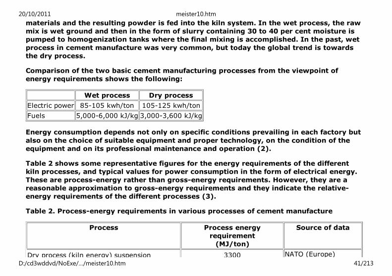
Comparison of the two basic cement manufacturing processes from the viewpoint of
energy requirements shows the following:
Wet process Dry process
Electric power 85-105 kwh/ton 105-125 kwh/ton
Fuels 5,000-6,000 kJ/kg 3,000-3,600 kJ/kg
Energy consumption depends not only on specific conditions prevailing in each factory but
also on the choice of suitable equipment and proper technology, on the condition of the
equipment and on its professional maintenance and operation (2).
Table 2 shows some representative figures for the energy requirements of the different
kiln processes, and typical values for power consumption in the form of electrical energy.
These are process-energy rather than gross-energy requirements. However, they are a
reasonable approximation to gross-energy requirements and they indicate the relative-
energy requirements of the different processes (3).
Table 2. Process-energy requirements in various processes of cement manufacture
Process Process energy
requirement
(MJ/ton)
Source of data
Dry process (kiln energy) suspension 3300 NATO (Europe)
20/10/2011 meister10.htm
D:/cd3wddvd/NoExe/…/meister10.htm 41/213
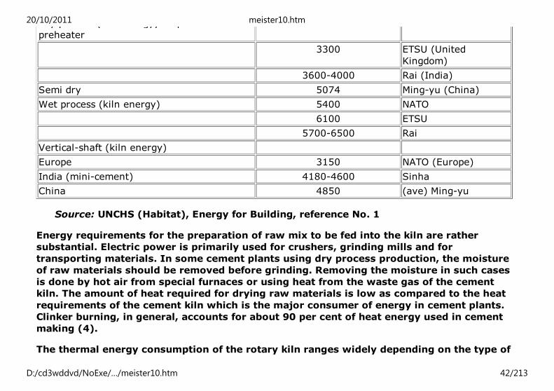
Dry process (kiln energy) suspension
preheater
3300 NATO (Europe)
3300 ETSU (United
Kingdom)
3600-4000 Rai (India)
Semi dry 5074 Ming-yu (China)
Wet process (kiln energy) 5400 NATO
6100 ETSU
5700-6500 Rai
Vertical-shaft (kiln energy)
Europe 3150 NATO (Europe)
India (mini-cement) 4180-4600 Sinha
China 4850 (ave) Ming-yu
Source: UNCHS (Habitat), Energy for Building, reference No. 1
Energy requirements for the preparation of raw mix to be fed into the kiln are rather
substantial. Electric power is primarily used for crushers, grinding mills and for
transporting materials. In some cement plants using dry process production, the moisture
of raw materials should be removed before grinding. Removing the moisture in such cases
is done by hot air from special furnaces or using heat from the waste gas of the cement
kiln. The amount of heat required for drying raw materials is low as compared to the heat
requirements of the cement kiln which is the major consumer of energy in cement plants.
Clinker burning, in general, accounts for about 90 per cent of heat energy used in cement
making (4).
The thermal energy consumption of the rotary kiln ranges widely depending on the type of
20/10/2011 meister10.htm
D:/cd3wddvd/NoExe/…/meister10.htm 42/213

process used, the quality and type of clinker required, kiln insulation, the effectiveness of
the operation control system, etc. As a result, the actual specific heat consumption varies
from about 3 to 7.5 GJ/t of clinker (4).
Wet and semi-wet processes
The advantages of the wet process, such as a simpler technological scheme for raw mix
preparations and its control, lower-labour input and less pollution of the environment, led
to its early extensive use in many countries. The basic disadvantage of this process as
compared to the dry process has been a higher consumption of heat for clinker burning, as
the water added to the raw mix has to be driven off in the kiln. Various efforts have been
made to increase energy efficiency in the wet process kiln through design improvements,
particularly by installing different types of heat exchangers in the kiln to improve the heat
transfer (4).
In the semi-wet process, the water content of the slurry is reduced before feeding it into
the kiln. Different types of filters can be used to reduce the water content to about 20 per
cent. The resulting mass is fed into the kiln, which can be equipped with a pre-heater. The
nodules obtained by filter-pressing of slurry and a shaping process are fed into the kiln.
The preheater-kiln system consumes 5 to 5.4 GJ/t of clinker (4).
20/10/2011 meister10.htm
D:/cd3wddvd/NoExe/…/meister10.htm 43/213

Figure 1. Energy consumption in cement grinding (kwh/t of cement). Courtesy Holtec
Engineering Private Ltd., India
Figure 2. Specific power consumption (kwh/t of cement). Courtesy Holtec Engineering
Private Ltd., India
Dry and semi-dry processes
20/10/2011 meister10.htm
D:/cd3wddvd/NoExe/…/meister10.htm 44/213

Dry process kilns came into existence along with wet process kilns. The major
development in dry process kilns was the introduction of external pre-heaters installed
before the kiln inlet. This has led to better heat economy, increase in kiln capacity and,
particularly in connection with the application of pre-calciners, making it possible to use
smaller kilns for a given capacity. The main advantage of dry process kilns with pre-
heaters is that the kiln gases pass over the raw mix thereby transferring their heat to the
raw mix before it enters the kiln. Thus, the raw mix undergoes the final drying and partial
calcination by using waste heat (4).
The four-stage cyclone suspension pre-heater-kiln system reduced specific heat
consumption to 3.3 to 3.6 GJ/t of clinker and allowed the creation of large-scale units of
upto 5,500 tonnes per day of clinker. The relatively high temperature of the raw mix
entering the kiln permits a significant reduction of the size of the rotary kiln. Both the
operation and maintenance of the cyclone suspension pre-heater are relatively simple,
because the pre-heater does not have any moving parts. The four-stage cyclone
suspension pre-heater-kiln system is today the most widely used conventional dry process
kiln in the cement industry. Further developments in clinker production have been
achieved by the introduction of the cyclone suspension pre-heaters with pre-calciners (4).
Although the reduction in specific heat consumption by adding pre-calciners to the
suspension pre-heater-kiln system is modest, namely, about 0.084 GJ/t of clinker, this
development has some advantages, which have led to its increasing use in developed and
developing countries. The main advantage is increased output per unit of kiln volume. For
a given capacity, the volume of the kiln can be reduced by approximately 60 per cent as
compared to the suspension pre-heater-kiln system, because the raw meal is decarbonized
up to 90 per cent in the pre-calciner. Another advantage, which is particularly important
from the energy point of view, is that low-grade fuels can be burned in the pre-calciner
thus saving high-grade fuels such as fuel oil, gas and high-grade coal. A third positive
factor relates to the environment: NOx emissions are significantly decreased (4).
20/10/2011 meister10.htm
D:/cd3wddvd/NoExe/…/meister10.htm 45/213

Energy-saving opportunities
Bearing in mind that about 85 per cent of the gross energy requirements in the production
of cement, is consumed in the kiln process where temperatures of about 1450°C are
reached (1), the potential for energy saving in the kiln process is remarkable.
Considerable improvements in energy efficiency are possible through the replacement of
wet-process with dry-process plants, through the installation of suspension heaters and
through improved kiln insulation. Studies have shown that the variations for energy
consumption between wet and dry process in rotary kilns could reach up to 86 per cent (a
wet process could consume 1400 kcal/kg of cement compared to 750 kcal/kg of cement in
the dry process) (5).
Small-scale plants using vertical-shaft kiln process are also better in terms of energy-
efficiency compared to wet-process, but less efficient than the best and modern dry
process plants.
Vertical shaft kilns have the lowest energy consumption, although they are smaller (in
general 20-200 t/d) than the large-scale rotary kilns (1000 to 4000 t/d). In India, for
example, it was established that while a vertical shaft kiln consumed around 750 kcal/kg
of clinker, a rotary kiln consumed up to 2000 kcal/kg of clinker. In addition to the
advantage of lower fuel consumption, the vertical shaft kilns are known to have operated
efficiently on a variety of solid fuels, sometimes with an ash content as high as 50 per cent
(6). Small-scale cement plants with vertical shaft kilns have inherent advantages of being
located in the rural areas of developing countries meeting local demand resulting in
reduced energy consumption for transportation. For a detailed treatment of the small-
scale production of cement see UNCHS (Habitat) “small-scale production of Portland
cement”, reference No. 7.
As mentioned earlier, the improvement of heat-use efficiency and the reduction of heat
20/10/2011 meister10.htm
D:/cd3wddvd/NoExe/…/meister10.htm 46/213

losses are of great importance in reducing the energy consumption in cement plants. To
that effect some important measures include (4):
(a) Energy savings in heating processes
A significant reduction of specific heat consumption in rotary kilns is achieved by using
modern dry process kilns with suspension pre-heaters or more advanced kilns with both
suspension pre-heaters and pre-calciners, where the heat of the exhaust gas of the kiln is
used for pre-heating the kiln feed. This can be realized when building new plants and/or
when expanding existing ones.
Another useful method to economize on fuel is changing the mineralogy in the cement and
utilizing mineralizers. Low-melting slags, fluoride and calcium sulphate are a few of the
numerous substances that render a mineralizing effect on clinker formation. A reduction of
clinker formation temperature, when utilizing the latter, leads eventually to saving of
energy.
The specific fuel consumption for calcining clinker could be reduced by approximately 10
per cent by changing the clinker mineralogy. Since the clinker produced by this process
features a high grinding ability, the specific consumption of electric power decreases
considerably and the capacity of the cement mills increases.
Significant attention is given to the development of industrial production of cement by
low-temperature technology with the use of calcium chloride, wherein the reaction in
mineral formation is completed at temperatures lower than in currently utilize
technologies.
Among the measures widely applied to improve heat use in rotary cement kilns are the use
of internal heat exchangers, e.g., chain systems used in wet and dry process kilns and
different thinners permitting reduction of the slurry moisture in the wet process that was
20/10/2011 meister10.htm
D:/cd3wddvd/NoExe/…/meister10.htm 47/213

described above.
Substantial reductions in heat losses from the kiln can be achieved by proper maintenance
of the kiln seals, control of combustion and improved refractories and cooling of the kiln
shell.
Losses from the wall of the rotary kiln make up a substantial share of total energy lost.
The heat transfer is reduced when the surface is insulated, but at the same time the
temperature of both the metal jacket and the lining rises. Thus, external insulation may be
detrimental to operating safely. One way of overcoming this is to utilize heat losses rather
than minimizing heat transfer. To this end, a recuperator is fitted at the top or on the side
of the rotary kiln. It is heated by some of the radiation emitted by the kiln.
Another opportunity for decreasing heat utilization in a cement plant is to use waste heat
from clinker coolers. This waste heat can be used in a number of ways, particularly to dry
raw materials, to dry coal when it is used for firing the kiln, or to generate steam and
power if necessary.
(b) Electric power savings
Cement mills are the major consumers of electric power at cement plants, accounting for
40 per cent of total electric power consumption. Therefore, primary attention is given to
improve efficiency in electric power utilization in these units as well as in the raw material
grinding mills, which are in second place in terms of consumption of electric power in
cement plants. Currently, clinker is ground mainly in ball mills whose energy efficiency is
low - only 5 to 9 per cent.
The basic method for reducing energy consumption in ball mills is their adjustment to
establish an optimum operating regime and to ensure maximum output with minimum
energy consumption while preserving the predetermined fineness of grinding. Another
20/10/2011 meister10.htm
D:/cd3wddvd/NoExe/…/meister10.htm 48/213

possibility of reducing the consumption of electric power is to improve the technology of
grinding in ball mills by pre-engagement of the crusher-drier. Preliminary crushing may
save energy in grinding up to 6 kwh/t raw material or 9 kwh/t of clinker.
To further increase the efficiency of the grinding process, it is necessary to employ
grinding units of other designs such as roller mills. But, when developing new methods of
grinding, it is necessary to ensure that economy in energy use does not cause offsetting
increases in capital and operating costs. Evidently, cement will be ground in the future
mostly in vertical mills.
The utilization of grinding intensifiers also ensures a certain energy saving. During recent
years many cement plants have started using grinding aids for clinker grinding as a means
of reducing electric power consumption and achieving increased output in the cement mill.
At present, roller mills appear to have some basic advantages in raw material grinding.
The use of a roller mill in raw material grinding can reduce electric power consumption by
about 20 to 25 per cent compared with that of a tube mill. However, a roller mill is in
general not suitable for processing abrasive raw materials.
(c) Substitution of fuels
Energy conservation means not only reduction of specific energy consumption per unit of
finished product but also preservation of scarce fuels such as fuel oil.
Many countries started reversing to coal after sharp increase in prices for oil-based fuels
in the 1970s. Even countries possessing significant oil deposits like Indonesia aim at
switching their cement plants from oil to coal and other low-grade fuels.
Widespread opportunities for using low-grade fuels for clinker burning were opened up by
the development of systems with cyclone pre-heaters and pre-calciners. Pre-calcining or
20/10/2011 meister10.htm
D:/cd3wddvd/NoExe/…/meister10.htm 49/213

secondary firing, apart from the possibility of achieving higher outputs, has also opened
the way for the saving of high-grade fuels and combustible industrial wastes such as wood
chips and bark, waste tyres, urban wastes, etc.
This is possible because the pre-calciner operates at a temperature of about 900°C which
is needed for decarbonation of the raw mix.
Only about a quarter of the total amount of heat used for clinker burning is consumed in
the kiln itself. Therefore, it is possible to feed up to 75 per cent of the fuel into the
secondary furnace in kilns with pre-calciners (in practice normally up to 60 per cent is
burnt in the pre-calciner). This allows the differentiation of fuel for calcining the clinker:
higher calorific fuel for ensuring high temperatures in the sintering zone of the rotary kiln
and less calorific fuel for ensuring decomposition of the carbonate component in the pre-
calciner.
In addition, many of the substances harmful to the environment are introduced into the
process together with the fuel and are bound almost completely in the cement clinker
without impairing its quality. Moreover, low-grade fuel can normally be used in the
process directly, i.e., without pre-treatment.
The potentialities for saving energy in the production of cement by utilizing energy-saving
technologies and measures are given in table 3.
Table 3. Potentialities for saving energy in the production of cement
Energy-saving technologies, equipment and measures Potential savings
Calcination of clinker Fuel (percentage)
Utilization of predehumified slurry, including the use of diluentsa
1-1.2 per one per
cent of moisture
20/10/2011 meister10.htm
D:/cd3wddvd/NoExe/…/meister10.htm 50/213

content reductionProduction of cement by dry method in kiln with decarbonizer:b
as compared with kilns with cyclone pre-heaters 5-7
as compared with the wet method 40-50
Intensification of the calcining process, including reduced suction of ambient
air, utilization of mineralizers, automatic control systems, efficient heat
exchangers, fuel combustion systems etc.
10-15
Utilization of ashes, slags and other materials, containing CaO, calcium
silicates or aluminatesc
10 or more
(depending on
additive)
Utilization of combustible industrial waste and domestic garbage equivalent to amount
of waste used as fuel
Utilization of fluidized kilns for calcining clicker (as compared with rotary
kilns)d
25-35
Utilization of secondary energy for electric power generation, raw material
drying
8-20
Clinker grinding Electric power
Milling cement in roller mills (as compared with ball mills)e 15-25
Utilization of milling intensifiers, optimization of granulometric composition,
etc.
10-15
Source: UNIDO/former CSSR Joint Programme, reference No. 2
a Increase of kiln capacity by 1.5-2 per cent of moisture content decrease.
20/10/2011 meister10.htm
D:/cd3wddvd/NoExe/…/meister10.htm 51/213

b Increase of specific capacity by 2.5 and 7.5 times, respectively and decrease of
specific consumption of refractories by 4 and 5 times.
c Savings in raw materials components.
d Reduction of capital investments by 20-30 per cent, potentiality for burning shale
and low-grade coal.
e Reduction in capital investments for construction, potentiality for additional
cooling of clinker in milling processes.
In addition to the above opportunities, other studies provide more information on
measures and possibilities for optimizing the use of energy in cement production. Table 4
is one of such compilation of information which provides examples from some countries.
Table 4. Selected examples of improvements in energy conservation and in specific energy
consumption in cement production
Plant
type/location
Energy savings Measure taken
A. Energy conservation
Wet Process Savings of 150 kcal/kg Adding a vent air recirculation system to clinker cooler
thereby reducing dust wastage and increasing heat
recuperation.
Dry Process Savings of 14 kcal/kg Addition of new kiln seal at end discharge end to cut out air
infiltration.
B. Lowering specific energy consumption
Wet Process 10 per cent (from Recirculating clinker cooler air.
20/10/2011 meister10.htm
D:/cd3wddvd/NoExe/…/meister10.htm 52/213
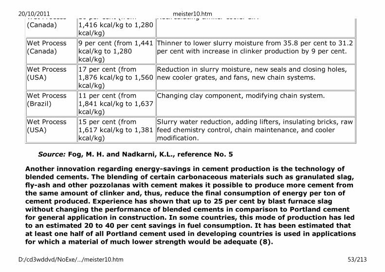
Wet Process
(Canada)
10 per cent (from
1,416 kcal/kg to 1,280
kcal/kg)
Recirculating clinker cooler air.
Wet Process
(Canada)
9 per cent (from 1,441
kcal/kg to 1,280
kcal/kg)
Thinner to lower slurry moisture from 35.8 per cent to 31.2
per cent with increase in clinker production by 9 per cent.
Wet Process
(USA)
17 per cent (from
1,876 kcal/kg to 1,560
kcal/kg)
Reduction in slurry moisture, new seals and closing holes,
new cooler grates, and fans, new chain systems.
Wet Process
(Brazil)
11 per cent (from
1,841 kcal/kg to 1,637
kcal/kg)
Changing clay component, modifying chain system.
Wet Process
(USA)
15 per cent (from
1,617 kcal/kg to 1,381
kcal/kg)
Slurry water reduction, adding lifters, insulating bricks, raw
feed chemistry control, chain maintenance, and cooler
modification.
Source: Fog, M. H. and Nadkarni, K.L., reference No. 5
Another innovation regarding energy-savings in cement production is the technology of
blended cements. The blending of certain carbonaceous materials such as granulated slag,
fly-ash and other pozzolanas with cement makes it possible to produce more cement from
the same amount of clinker and, thus, reduce the final consumption of energy per ton of
cement produced. Experience has shown that up to 25 per cent by blast furnace slag
without changing the performance of blended cements in comparison to Portland cement
for general application in construction. In some countries, this mode of production has led
to an estimated 20 to 40 per cent savings in fuel consumption. It has been estimated that
at least one half of all Portland cement used in developing countries is used in applications
for which a material of much lower strength would be adequate (8).
Note For a detailed treatment of small scale cement production refer to UNCHS (Habitat), “Small
20/10/2011 meister10.htm
D:/cd3wddvd/NoExe/…/meister10.htm 53/213

Note
1.
For a detailed treatment of small scale cement production refer to UNCHS (Habitat), “Small
scale production of Portland Cement”, reference No. 7
Note
2.
For a detailed treatment of blended cements and other types of binding materials see UNCHS
(Habitat), Endogenous Capacity-Building for the Production of Binding Materials in the
Construction Industry-Selected Case Studies, reference No. 9.
2.2. Lime
The production process of lime, like cement production, is highly energy-intensive, but
energy requirements in lime production are lower than cement and the types of fuels
required could be a variety of low-grade fuels.
Quicklime is manufactured by calcining limestone at temperatures around 900°C which is
almost 35 per cent lower than the heat required for cement clinker production. A high
proportion of the total energy requirement in lime production is used in kiln for calcining
the limestone. Thus, as in the case of cement, the principal means of achieving energy-
efficiency lies in improving the performance of the kilns. In industrialized countries,
production of quicklime is done by burning the limestone in large and fully automated
rotary kilns. However, in most developing countries, a vertical shaft kiln, using simple
masonry for the wall of the kiln is more common.
Rotary kilns are similar to those used in the cement industry. Rotary kilns have evolved
into short rotary kilns with separate pre-heaters, resulting in lower waste gas
temperatures. The original design had a specific energy consumption of 6.6 to 8.4 GJ/t
and capacities up to 560 tonnes per day. The short kiln can be made more energy efficient
with specific energy consumption as low as 5.0 GJ/t, though there are instances of such
kilns which do not capitalize on this energy-saving potential. Capacities of the short kiln
range from 200 to 1,000 tonnes per day (2).
20/10/2011 meister10.htm
D:/cd3wddvd/NoExe/…/meister10.htm 54/213

Vertical-shaft lime kilns, however, have, proved to be one of the most suitable and
economical methods of small-scale lime production in many developing countries (3 to 10
t/d capacity). For example, a vertical-shaft lime kiln can burn lime on a continuous basis
resulting in considerable savings in heat losses. The kiln, having three distinct zones of
operations (preheating, calcining and cooling), is attractive and efficient in terms of use of
fuel. Further efficiency can be achieved by incorporating insulation in the wall of the kiln.
These are only a few characteristics that make the use of the vertical-shaft lime-kiln
technology more advantageous than the other traditional methods. For a detailed
treatment of the vertical-shaft lime-kiln technology see UNCHS (Habitat), Vertical-shaft
Lime-kiln Technology, reference No. 10.
Energy use in quicklime production
As mentioned earlier, the main energy requirements for the production of quicklime is in
burning the lime stone in the kiln. The other energy inputs are required for limestone
quarrying, grinding, and hydrating/slaking the quicklime. Table 1 shows the energy
requirements for quicklime production in various types of kilns and countries.
Table 1. Energy requirements of quicklime production from various sources
Process and scale Scale of
production
(ton/day)
Energy
requirement
(GJ/ton)
Efficiency
(percentage)
Source of
data
Traditional intermittent kiln,
India
Very small 12.6 25 Rai
Conventional shaft kiln, India 10-20 9.03 35 Rai
Improved shaft kiln, India 10-20 6.24 51 Rai
Improved shaft kiln, Malawi 3 6.92 46 SpiropoulosMechanized vertical 20-100 4.76 67 Rai
20/10/2011 meister10.htm
D:/cd3wddvd/NoExe/…/meister10.htm 55/213

Mechanized vertical 20-100 4.76 67 Rai
Rotary kiln <100 6.71 48 Rai
National studies
Argentina 3.8
Germany 8.8
India 6.34
Source: UNCHS (Habitat), Energy for Building, reference No. 1
Table 2. Fuel consumption in lime production using different technologies
Country Type of kiln Proportion of
production cost
Primary energy consumption
MJ/kg quicklime
Federal Republic of
Germany
Traditional vertical
kiln
35 4.760
Ring annular kiln 22 4.865
Rotary kiln 20 6.715
Traditional kiln - 12.60
Conventional - 9.03
Improved shaft
kiln (CBRI)
- 6.24
Source: UNCHS (Habitat), Technical Note No. 12
As can be seen, traditional intermittent kilns can be very wasteful of fuel, with only 25 per
cent of efficiency. Whereas the improved kilns can have an efficiency of up to 50 per cent
even if in small-scale.
20/10/2011 meister10.htm
D:/cd3wddvd/NoExe/…/meister10.htm 56/213

Fuel consumption in alternative technologies for production of hydrated lime tends to
show the importance of choice of technology in achieving energy efficiency. Using the case
study of the Federal Republic of Germany in table 2, an energy saving of about 40 per cent
is achieved when rotary kiln technology is adopted in place of a traditional vertical kiln.
Energy-saving opportunities
In vertical-shaft small-scale lime production, almost 60 per cent of the production cost is
constituted by the cost of fuel alone.
The main fuel sources for lime-burning are coal, coke, cinder, wood, oil, gas etc. With the
depleting resources of fossil fuel, it has become necessary to reduce the consumption of
energy for the production of quicklime. Therefore, any saving in the consumption of
energy will result in lowering the cost of production (10).
Energy savings could be achieved by changing the design parameters of the kiln. Studies
and experiments carried out indicate that heat-energy savings could be achieved to the
tune of 50 per cent by changing the design only. This indicates a potential for further
savings by continuous research and development in limekilns (10).
An example of the energy savings achieved by improved limekiln design is illustrated in
table 3 (10).
Table 3. Average energy inputs for 1 kg quicklime (CBRI limekiln)
Constituent of energy consumption Energy consumption (kcal/kg)
Country type
kiln
Conventional
shaft kiln
CBRI
improved kiln
Theoretical heat requirement for calcination for 750.0 750.0 750.0
20/10/2011 meister10.htm
D:/cd3wddvd/NoExe/…/meister10.htm 57/213

Theoretical heat requirement for calcination for
pure limestone
750.0 750.0 750.0
Sensible heat loss through exhaust 1050.0 850.0 850.0
Heat loss due to underburnt limestone 500.0 200.0 100.0
Wall heat loss 75.0 75.0 5.0
Sensible heat loss from quicklime 250.0 25.0 25.0
Radiation losses from top surfaces 150.0 125.0 75.0
Heat loss due to incomplete burning of fuel 100.0 75.0 10.0
Excess air loss 125.0 50.0 25.0
Gross energy input (kcal/kg CaO) 3000.0 2150.0 1660.0
Source: Central Building Research Institute (CBRI), Roorkee, India
20/10/2011 meister10.htm
D:/cd3wddvd/NoExe/…/meister10.htm 58/213

Figure 1. Flow chart of vertical-shaft lime kiln production in Balaka, Malawi. Courtesy
Brian Jones
The CBRI improved shaft kiln has been achieved through the principles of uniformity of
heat distribution over the cross section of the kiln plus the provision of a good draught
system. In detail, the CBRI kiln is a tall cylindro-conical structure constructed of masonry
material with an internal lining of fired-clay bricks. The effective height of this kiln for a 10
tonne per day capacity is 11m and the calcining zone maintains a temperature of 950°C to
1100°C (11).
20/10/2011 meister10.htm
D:/cd3wddvd/NoExe/…/meister10.htm 59/213

Figure 2. An improved shaft kiln developed by KVIC, India
In rotary kilns, the highest losses are waste gases leaving the plant at a temperature of
250° to 350°C. These gases are always mixed with secondary air getting in at the interface
between rotary kiln and pre-heater. If the plant were completely sealed, the waste gas
temperature would rise to 430°C. This would not affect the balance sum of waste gas
losses, because the over-all amount of waste gas would be reduced accordingly (4).
All energy-saving opportunities seem to be already realized in the most efficient shaft
furnaces, particularly in the parallel-flow-counterflow-regenerative furnace. Waste gases
emitted from this furnace range between only 60° and 140°C; further reduction would risk
condensation and corrosion of equipment (4).
When a new kiln is constructed, the preferred kiln types are of the regenerative shaft kiln
type. Specific heat consumption as low as 3.5 kj/kg is possible in this type of kiln.
20/10/2011 meister10.htm
D:/cd3wddvd/NoExe/…/meister10.htm 60/213

However, an exception to this may occur if, for example, the disintegrating property of
chalks and some coarsely crystalline limestones results in the shaft kiln being choked off
by dust formed from the complete disintegration of these materials during burning. In this
situation, the rotary kiln, fitted with a heat exchanger to recover waste gas heat, would be
the most energy efficient solution (4).
For further information on lime production and some case studies see UNCHS (Habitat),
“Endogenous Capacity-Building for the Production of Binding Materials in the Construction
Industry-Selected Case Studies”, reference No. 9 as well as UNCHS (Habitat), Vertical-
shaft Limekiln Technology, reference No. 10.
2.3. Clay bricks
As in the cement and lime industry, most of the energy used in brick manufacture is
required to fire the bricks - typically more than 95 per cent of all energy use. There are
considerable differences between the energy requirements for different types of brick
kilns, depending on whether the firing is continuous or intermittent, on the size and heat-
transfer efficiency of the kiln and on whether the brick-earth used contains combustible
materials (12).
Experience has shown that, beyond a daily output of 10,000 bricks, economies of scale are
small and that low-capital-cost kilns, such as the Indian Bull’s trench kiln, can have a fuel
efficiency comparable with the expensive covered Hoffman kilns used in European
countries. A recent study of the brick industry in Delhi (13) showed that detailed
differences in the design of the trench kiln contributed to significant variations in energy
efficiency. Overall, the bricks produced by the process had an average fuel consumption of
1.8 MJ per kg of bricks produced, but with individual kilns’ fuel consumption varying from
100 to over 300 kilograms of coal per 1000 bricks. Research on the kiln process at the
Central Building Research Institute (CBRI), Roorkee, India, has led to the development of
20/10/2011 meister10.htm
D:/cd3wddvd/NoExe/…/meister10.htm 61/213
an improved but more expensive high-draught kiln design which is reported to reduce
energy consumption by 25 per cent, compared with a typical trench kiln (13).
The scarcity and rising prices of coal, the predominant fuel used for brick-firing, are
forcing brick producers to look for cheap fuel substitutes as well as energy economies.
The study of the Delhi industry showed that increasing numbers of producers were using a
proportion of unconventional fuels, such as fuelwood, rice husks, sawdust and agricultural
waste, and that these producers were able to lower costs without it being detrimental to
the quality of the bricks, though at the cost of a small lowering of energy efficiency. A
small number of producers had eliminated coal entirely, with a resulting increase in
energy consumption of only 14 per cent compared with producers using coal alone (14).
The theoretical energy requirement for firing clay bricks in small-scale kilns is about 20 to
35 per cent of the actual energy consumption in production practice. Thus, most existing
brick production technologies are by definition energy-inefficient. Table 1 shows some
examples for energy requirements related to the size of plants.
Since transportation of bricks from the point of production to the point of use accounts for
a significant amount of energy consumption, it could be argued that the scale of
production is a critical determinant of efficiency in energy utilization. Large-scale
production technologies predetermine high-energy consumption for distribution because a
single plant often has a wide catchment zone, sometimes an entire country. Large scale
brick industries are examples of prevailing error in choice of scale of technology as far as
energy-efficiency in transportation is concerned.
Table 1. Energy consumption in brick-making technologies
Technology Scale of
production
Labour required
(man-hr for 1000
Over-all energy
consumption
20/10/2011 meister10.htm
D:/cd3wddvd/NoExe/…/meister10.htm 62/213

(No. of
bricks)
solid bricks) (MJ/1000 solid
bricks)
Small-scale production, all manual methods,
clamps, stoves, scotch kilns
2,000 20 to 30 7,000 to 10,000
Small-scale production, all manual methods,
up draught and down draught kilns
2,000 30 to 40 10,000 to 15,000
Medium-scale production, all manual methods,
Bull’s kilns
20,000 30 to 40 4,000
Medium-scale production, semi-mechanized
method, Hoftmann on zig-zag kiln
30,000 30 to 35 3,000 to 3,500
Large-scale production, full mechanized tunnel
kiln
150,000 10 to 15 3000 to 4000
Source: UNCHS (Habitat), Technical Note No. 12
In addition to the size of kilns, the actual amount of fuel required to burn a given amount
of bricks would depend, among others, on the following factors:
(a) characteristics of raw material (clay);
(b) porosity of bricks;
(c) volume of water (moisture) to be evaporated;
(d) quality of the carbonaceous matters in the bricks;
(e) temperature to be attained;
(f) reuse of hot air generated in the kiln;
(g) quality of fuel.
Table 2 shows fuel requirements of intermittent and continuous kilns which is based on a
study carried out in Pakistan (15).
20/10/2011 meister10.htm
D:/cd3wddvd/NoExe/…/meister10.htm 63/213

Table 2. Typical fuel requirements of kilns
Type of Kiln Heat Requirement
(MJ/1000 Bricks)
Quantity of Fuel Requirement
(Tons/1000 Bricks)
Wood Coal Oil
Intermittent 7,000 to 15.000 0.50-1.0 0.25-0.6 0.15-0.35
Continuous 2,000 to 5,000 0.15-0.3 0.10-0.2 0.05-0.1
Source: Mohammed Khalid Farooq, Pakistan, reference No. 15
Due to scarcity of coal in many developing countries (which are not covered in high
priority segment for allotment of coal or railway wagons for its transportation) and rising
prices of electricity or petroleum products, the introduction of modern technology in the
industries manufacturing bricks, lime, ceramics, etc is a difficult task. Summary of a study
carried out by UNIDO and ILO on the average fuel requirements for kilns is given in table
3.
Table 3. Fuel requirements for brick-making using different kiln types
Type of kiln Heat requirement
(MJ/1,000 bricks)
Quality of fuel required
(tons/1,000 bricks)
Wood Coal Oil
Intermittent
Clamp 7,000 (0.44) 0.26 (0.16)
Stove 16,000 1.00 0.59 0.36
Scotch 16,000 1.00 0.59 0.36Downdraught 15,500 0.97 0.57 (0.35)
20/10/2011 meister10.htm
D:/cd3wddvd/NoExe/…/meister10.htm 64/213
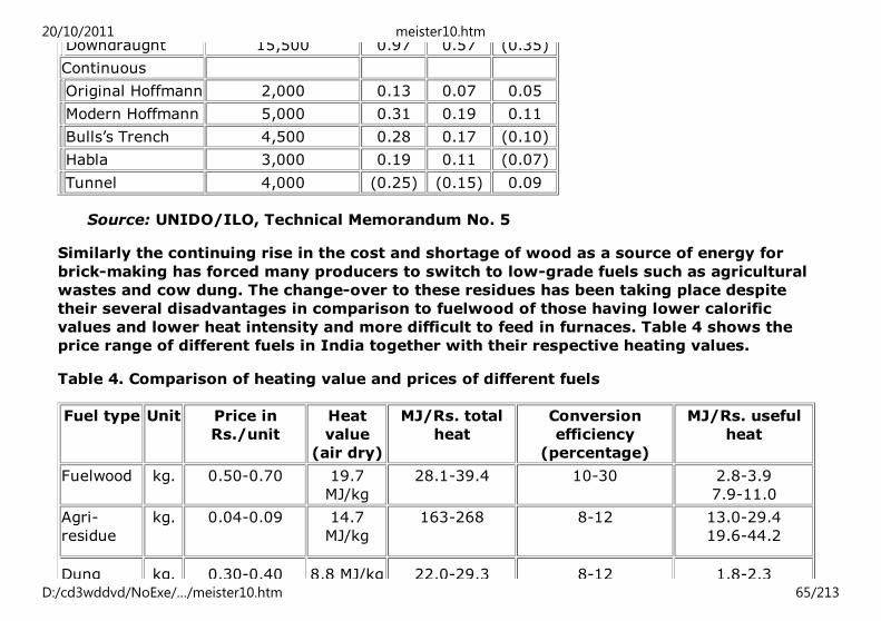
Downdraught 15,500 0.97 0.57 (0.35)
Continuous
Original Hoffmann 2,000 0.13 0.07 0.05
Modern Hoffmann 5,000 0.31 0.19 0.11
Bulls’s Trench 4,500 0.28 0.17 (0.10)
Habla 3,000 0.19 0.11 (0.07)
Tunnel 4,000 (0.25) (0.15) 0.09
Source: UNIDO/ILO, Technical Memorandum No. 5
Similarly the continuing rise in the cost and shortage of wood as a source of energy for
brick-making has forced many producers to switch to low-grade fuels such as agricultural
wastes and cow dung. The change-over to these residues has been taking place despite
their several disadvantages in comparison to fuelwood of those having lower calorific
values and lower heat intensity and more difficult to feed in furnaces. Table 4 shows the
price range of different fuels in India together with their respective heating values.
Table 4. Comparison of heating value and prices of different fuels
Fuel type Unit Price in
Rs./unit
Heat
value
(air dry)
MJ/Rs. total
heat
Conversion
efficiency
(percentage)
MJ/Rs. useful
heat
Fuelwood kg. 0.50-0.70 19.7
MJ/kg
28.1-39.4 10-30 2.8-3.9
7.9-11.0
Agri-
residue
kg. 0.04-0.09 14.7
MJ/kg
163-268 8-12 13.0-29.4
19.6-44.2
Dung kg. 0.30-0.40 8.8 MJ/kg 22.0-29.3 8-12 1.8-2.3
20/10/2011 meister10.htm
D:/cd3wddvd/NoExe/…/meister10.htm 65/213
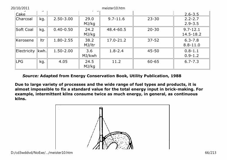
Dung
Cake
kg. 0.30-0.40 8.8 MJ/kg 22.0-29.3 8-12 1.8-2.3
2.6-3.5Charcoal kg. 2.50-3.00 29.0
MJ/kg
9.7-11.6 23-30 2.2-2.7
2.9-3.5
Soft Coal kg. 0.40-0.50 24.2
MJ/kg
48.4-60.5 20-30 9.7-12.1
14.5-18.2
Kerosene ltr 1.80-2.55 38.2
MJ/ltr
17.0-21.2 37-52 6.3-7.8
8.8-11.0
Electricity kwh. 1.50-2.00 3.6
MJ/kwh
1.8-2.4 45-50 0.8-1.1
0.9-1.2
LPG kg. 4.05 24.5
MJ/kg
11.2 60-65 6.7-7.3
Source: Adapted from Energy Conservation Book, Utility Publication, 1988
Due to large variety of processes and the wide range of fuel types and products, it is
almost impossible to fix a standard value for the total energy input in brick-making. For
example, intermittent kilns consume twice as much energy, in general, as continuous
kilns.
20/10/2011 meister10.htm
D:/cd3wddvd/NoExe/…/meister10.htm 66/213

20/10/2011 meister10.htm
D:/cd3wddvd/NoExe/…/meister10.htm 67/213

Figure 1. Working method of the Bull’s Trench continuous kiln. Courtesy BRE, U.K.
It is, therefore, advisable to establish necessary measures which should be based on trial
firing in each case and/or replicate identical processes as far as it is possible. Obviously,
maintaining uniformity of raw materials and fuel types and continuous maintenance of kiln
operation would lead to reduced deviations in the amount of fuel required in a given plant.
Hence, reasonably accurate forecast of fuel consumption for a foreseeable future of plant
operation.
Energy-saving opportunities
As mentioned earlier, one of the major energy-saving opportunities lies in converting,
where possible and feasible, the intermittent kilns such as clays or simple updraught kilns,
to continuous kilns: the latter include the Bull’s trench kiln, the Hoffman kiln and the
tunnel kiln. Experience has shown that a coal-fired Bull’s trench kiln, of the type common
in India and Pakistan, is several times more efficient as a sophisticated oil-fired clamp one
and almost as efficient as a sophisticated oil-fired tunnel kiln. In China, Fuyin, Y., and
others have developed a small-scale continuous updraught kiln, fired on coal, wood or
agricultural waste, which has excellent efficiency.
Where it is considered necessary to use intermittent kilns, improvement may be made to
enhance fuel efficiency by:
- ensuring that even temperatures are obtained throughout the kiln;
- reducing heat losses through the sides and top surface of the kiln; and
- recovering heat from the combustion gases. This can be achieved through use of
20/10/2011 meister10.htm
D:/cd3wddvd/NoExe/…/meister10.htm 68/213

scotch or updraught kilns with permanent sidewalls rather than open clamps, and
improvement of insulation of clamp kilns.
where continuous kilns are used, strategies for energy savings can be achieved by:
- increasing chimney heights;
- adopting a fixed rather than the traditional moving chimney design; and
- careful control of the levelling of the kiln floor. Process control such as sealing
the kiln, adequate drying of the green bricks, and uniform feeding of the fuel also
contribute to energy saving.
The Central Building Research Institute in Roorkee, India, has carried out extensive
research on kiln processes and has found out that a reduction of 25 per cent on fuel
consumption can be achieved by improvements in the high-draught kiln designs compared
with the typical trench kilns. But the capital requirements of such a kiln is almost 10 times
that of the traditional kiln which is a major bottleneck for small-scale brick producers to
afford such an initial investment (3).
Changes in fuel type and addition of solid-fuel particles such as coal dust, sawdust, coffee
or rice hulls or, even, plastics such as polystyrene, to the clay can increase energy
efficiency but affect the characteristics of the brick, e.g., porosity, strength. This is not
necessarily a disadvantage, but it is necessary to take these different properties into
consideration during design and construction stages. Similarly, hollow bricks will save
energy (5 to 6 per cent per 10 per cent of hollowness) but will have different properties
from solid bricks. Several of the improvements noted above have been implemented in
brick-making in Indonesia, as part of a Technical Assistance Programme, and include:
(a) introduction of perforations in hand-made and extruded bricks;
20/10/2011 meister10.htm
D:/cd3wddvd/NoExe/…/meister10.htm 69/213

(b) use of combustible filler (e.g., rice husk) in the clay body;
(c) improved body-clay preparation; and
(d) control of air supply and waste gas in kilns. The results of this programme have
not yet been assessed (16).
Waste engine oil can be an alternative fuel in some areas. Waste engine oil is often
disposed of in such a way that it causes serious water pollution, and using it as a fuel
would greatly reduce this problem. Waste engine oil can be utilized in simple gravity drip-
feed flat-plate burners which vaporize the oil: such a method has been successfully used
to fire a 35 cubic-foot pottery kiln at Arusha, the United Republic of Tanzania.
Alternatively, sophisticated forced-air burners can be employed which use blowers to
atomize the fuels. To use waste oil most effectively, a combination of fuels is required.
Moreover, to start the firing using flat-plate burners, wood or other biomass can be used
(17).
Another opportunity for saving energy in the overall process of brick-making is the use of
solar energy for drying the green brick in countries with dry and warm climate.
20/10/2011 meister10.htm
D:/cd3wddvd/NoExe/…/meister10.htm 70/213

Figure 2. A rectangular down-draught kiln. Courtesy UNIDO/ILO, Small-scale brick making
Figure 3. Sun drying of green bricks is common in dry and warm climates. Courtesy BRE,
U.K. (a)
20/10/2011 meister10.htm
D:/cd3wddvd/NoExe/…/meister10.htm 71/213

Figure 3. Sun drying of green bricks is common in dry and warm climates. Courtesy BRE,
U.K. (b)
20/10/2011 meister10.htm
D:/cd3wddvd/NoExe/…/meister10.htm 72/213

Figure 4. Design of brick kiln using rice-husk as fuel. Courtesy Satya Prakash and F. U.
Ahmed, CBRI, Roorkee, India
2.4. Ceramic wall and floor tiles (2)
Ceramic products for interior and exterior protection and decoration of all types of
commercial and residential buildings are of great importance. Earthenware, tiles and
mosaics are included in this group. Energy consumption of both glazed and unglazed
products is high and covers a broad range depending on the individual product.
Energy consumption in ceramics production is concentrated in the following processes
and activities:
- Dressing and shaping;
20/10/2011 meister10.htm
D:/cd3wddvd/NoExe/…/meister10.htm 73/213

- Handling and internal transport;
- Drying and firing, which together account for about 85 per cent of energy
consumption.
Wall tile
The traditional manufacturing process consists, with the exception of body preparation
and pressing, of three phases: drying, bisque and glost firing after glazing.
The traditional manufacturing process, based on kaolinitic-clay, semi-silicious or feldspar
body composition, requires bisque firing temperatures in the range of 1,230°C to 1,280°C.
Glazed bisque is fired at 1,080°C to 1,120°C. Decreased firing temperatures, of 1,050-
1,080°C for bisque firing and 960-1,040°C for glazing, can be achieved by replacing those
bodies with lime-silicious, dolomite-silicious and certain other raw materials. Significant
energy savings are possible through the lower-temperature firings, which newer materials
allow.
Ceramic glazes
Properties of ceramic glazes have to correspond to the ceramic body properties and to
quality and appearance requirements.
The last 50 years of technological progress in the production of ceramic glazes has
paralleled that of ceramic bodies. Opaque zircon glazes based on potash feldspar are fired
at temperatures of about 1,120°C. These glazes are for glazing kaolinitic-clay bodies. The
application of calcium-silicious body in the manufacture has allowed the development of
new types of glazes with sodium-lime feldspar and lead content, which are melted at firing
temperatures of only 960° to 1,040°C.
Further development of glazes should result in single ceramic processes at temperatures
20/10/2011 meister10.htm
D:/cd3wddvd/NoExe/…/meister10.htm 74/213
as low as 900°C.
Opportunities for energy conservation
There exist several possibilities for energy conservation in the ceramic floor and wall tile
industry. The most important among these are the following:
- Further reduction of firing temperatures through the application of fluxes and
corresponding glazes;
- Replacement of the double firing by the single firing process for energy savings of
40 to 50 per cent;
- Proper adjustment of existing kilns to reduce energy consumption usually by 10
to 20 per cent;
- Use of waste heat from the cooling zones of kilns, for example, to pre-heat
combustion air;
- Use of waste heat from flue gases in technological processes;
- Use of modern equipment for drying and firing where about 85 per cent of total
energy in the overall production process is consumed.
Home"" """"> ar.cn.de.en.es.fr.id.it.ph.po.ru.sw
Global Overview of Construction Technology Trends: Energy
Efficiency in Construction (HABITAT, 1995, 210 p.)
20/10/2011 meister10.htm
D:/cd3wddvd/NoExe/…/meister10.htm 75/213

3. Innovative technologies related to the increased utilization of
low-energy building materials3.1. Soil construction
3.2. Building stone, sand and aggregates
3.3. Low-cost binders
3.4. Timber and bamboo
Global Overview of Construction Technology Trends: Energy Efficiency in Construction
(HABITAT, 1995, 210 p.)
3. Innovative technologies related to the increased utilization of low-energy building
materials
3.1. Soil construction
Unlike energy-dependent building materials which consume predominantly thermal energy
resources, the energy requirements for modern soil construction are mainly in the form of
electrical and mechanical energy to run a variety of mixing, extrusion, ramming and
compaction of soil blocks. In this context, it could be argued that soil construction, even in
its most technologically-sophisticated form, is capital-intensive and hardly energy-
demanding. There is a wide range of soil construction technologies that utilize capital
items in one form or another. One important asset in these technological trends is that
there are different scales of capital intensity and, by implication, energy expenditure,
including technologies with no energy requirement. In fact, in most small-scale
operations, every stage of the soil construction process is manual, utilizing simple tools,
20/10/2011 meister10.htm
D:/cd3wddvd/NoExe/…/meister10.htm 76/213
and the only energy requirement is related to transportation of materials. However, where
appropriate soils are obtainable near the construction site, there is hardly any expense in
transportation and, perhaps, this is the greatest potential in soil construction as an
indigenous low-cost material (18).
The selection of building materials, in general should aim at providing the most desirable
levels of climatic comfort. In countries with harsh weather conditions, especially where
there are extreme seasonal or daily variation in temperature, climatic comfort and, by
implication, the thermal characteristics of the building materials used, are as important as
their durability.
Climate conditions of countries such as the Middle East and the Arabian Peninsula
although, generally, hot and dry, tend to vary sharply between summer period and winter
months, thus making climatic conditions of utmost importance in the choice of materials
for low-cost housing.
In this connection, it should be mentioned that soil, in comparison to several other
materials, has a relative advantage due to its good capacity to store heat. Soil has a latent
inertia related to its absorption capacity and has a significant ability to delay thermal
variations and external thermal inflows. These properties are valuable in areas,
characterized by highly variable climatic and atmospheric conditions. Perhaps the greatest
asset of soil in relation to its thermal performance, is the ease with which its specific
gravity can be altered for construction. This is particularly noticeable when soil blocks are
made of clay and straw. With the soil-straw technique, it is possible to produce blocks
with a bulk density as low as 300 kg/m3 and a corresponding high insulation value of 2.80
m2.°C/W, while solid concrete blocks have a bulk density of 2,400 kg/m3 and an
insulation value of 0.24 m2.°C/W (19).
A brief review of soil construction technologies
20/10/2011 meister10.htm
D:/cd3wddvd/NoExe/…/meister10.htm 77/213

The most predominant examples of soil construction are the outcome of traditional
practices but, unfortunately, technological errors are common in these constructions. The
underlying principles of modern soil technology are a response to the defects of the
traditional practices. A great deal of technological achievements in soil construction are
replicas of other building materials technologies, notably fired-clay bricks and concrete.
The three most common modern soil construction technologies are rammed earth, adobe
construction and compressed-block technology. In several aspects, rammed earth
technology is similar to monolithic concrete techniques, adobe is close to unfired-clay
brick, while the production of compressed-soil blocks follow the same principles of
concrete-block manufacturing.
(a) Rammed earth
The quality of soil is an important criteria for good quality rammed earth construction. The
suitable soils should have adequate cohesiveness and should contain sandy aggregates to
the point that they attain characteristics similar to those of lean concrete. When the
available soils are clayey (have high plasticity index-PI), they should be mixed with soils
containing a high percentage of gravel and sandy fraction. In the preparation of soil for
rammed earth construction, depending on the location and size of construction projects,
both manual and mechanical methods can be applied. The mechanical process, which
obviously, would require some energy input, vary from simple technologies to
sophisticated automated equipment. One important advantage of rammed earth
technology is that its use in movability wall construction allows for a variety of forms such
as round corners. In temperate climates, it is not advisable to carry out rammed earth
construction less than three months before or during the frost period. In hot-humid
climates, the rainy periods should be avoided, while in hot-dry climates, the hottest
season should be avoided.
Owing to the similarity between rammed earth construction and in situ concrete
20/10/2011 meister10.htm
D:/cd3wddvd/NoExe/…/meister10.htm 78/213
technology, most of the machinery used in concrete works are directly applicable to
rammed earth. However, the two most distinguishable and important activities in rammed
earth construction are formwork and ramming.
One weakness of rammed earth construction is that the walls are liable to crack after a
period of time if not properly constructed. These negative aspects can be minimized by
means of putting the walls on strong foundation, using soil stabilizers, surface protection
or patching up the cracks as a remedial measure.
20/10/2011 meister10.htm
D:/cd3wddvd/NoExe/…/meister10.htm 79/213

Figure 1. Different types of formwork for rammed earth construction
Formwork
20/10/2011 meister10.htm
D:/cd3wddvd/NoExe/…/meister10.htm 80/213

Formwork for rammed earth must be solid and stable in order to resist the pressure and
vibrations resulting from ramming. In addition, it should be made of lightweight material
and it must be easy to assemble and dismantle. The formwork must also be capable of
accommodating changes for the height, length and thickness of walls. A broad range of
materials, such as timber, glass fibre, steel and aluminium, can be used for manufacture of
formwork. Depending on the type of building, available workforce and equipment,
formwork can be organized as either a system consisting of small units or an integral
formwork. Integral formwork is normally used when the design to be executed is
relatively simple and it is presented in a simple format adopting modular dimensions.
Movement of formwork on site can be done by gantry formwork. This technique is best
suited for the erection of columns or wall sections. Such formwork should be light,
consisting of simple planks, plywood panels or even billets, which should be kept in
position by wooden supports driven into the ground and secured at the top. Other
techniques for movement of formwork on site are the use of rollers and sliding formwork
as in modern concrete practice.
Rammers
The performance of a building made of rammed earth depends largely on the efficiency of
the ramming technique. Ramming is the most tedious process in the entire operation and,
depending on the choice of technique, there could be some minimal energy required. There
are two types of rammers - manual and mechanical. The key elements for manual ramming
are:
(a) an effective striking face: a striking angle of 60° or more with detailing in the
shape to cater for difficult angles in the formwork;
(b) a striking area of not more than 225 sq cm;
20/10/2011 meister10.htm
D:/cd3wddvd/NoExe/…/meister10.htm 81/213

(c) a durable material for the striking head, preferably solid metal;
(d) a handle of about 1.4 m; and
(e) the total weight of the rammer should range between five and nine kilograms.
There are two types of mechanical ramming, i.e. impact and vibrating ramming. Impact
ramming consists of pneumatic rammers which have been adapted from the foundry
industry. Their function is similar to that of manual rammers except for a higher impact
frequency (up to 700 strokes per minute). Pneumatic rammers must not exceed 15 kg in
weight and should not be too powerful, otherwise they tend to destabilize the formwork
causing the earth to bulge or rather the rammer might penetrate the soil. Vibrating
rammers are powered by combustion engines or electric motors and are heavy,
cumbersome and expensive yet not proven to be effective particularly, in remote areas.
(b) Adobe technology
Adobe technology is equivalent to that of fired-clay bricks except for the fact that while
fired-clay technology relies on a kiln process with high energy requirement, adobe
technology replaces this process with open-air sun-drying. The soils used for adobe
should be plastic or cohesive in texture. Clayey soils are thus the most suitable for adobe
manufacture, but it is important to select those clays which are not generally expansive.
Sometimes sandy soils have to be added to the clay to achieve the right quality of soil.
The first step of adobe blocks is pugging the clay. Because of the cohesive nature of soils,
the pugging of clays could sometimes be a long operation. Traditionally, the clayey soil is
mixed with water and sometimes with bare feet until a consistent mixture is obtained.
Animals are sometimes used to knead the soil with their hooves. The manual processes of
kneading clay are extremely labourious and thus make mechanized options easily
attractive. Mixing is the most important operation in the production process if the soils
20/10/2011 meister10.htm
D:/cd3wddvd/NoExe/…/meister10.htm 82/213

used require an admixture such as sandy soils or stabilizers. Standard concrete mixers can
be adapted to this practice but there are other technologies which are particularly suited
for soil mixing. Vertical mixers can be fabricated on the site using planks, timber sections,
ropes and steel wire with animal-driven power. There are also standard vertical mixers on
a commercial scale capable of handling 10 cu m per day. Similar linear mixers adapted
from the ceramic industry are available with rated capacities of up to 50 cu m per day.
Manual moulding
To produce good quality, dense, and resistant adobe bricks, it is advisable to use a clay
mixture that is semi-solid in texture which implies the use of the sand-moulding
technique. Small-scale moulding tables from the brick industry can be adapted to this
technique. A typical example is the ITDG moulding table with an output of about 500
bricks per day (20). The manual technique of adobe production can be adapted to large-
scale production. The key item is the multiple mould. The clay mixture should be liquid in
consistency so that it can be easily spread manually to fill all the moulds in one single
operation. It is important to ensure that the multiple mould can be handled by two
persons and that blocks can be easily demoulded. With this technique it is possible to
produce 8,000-10,000 blocks per day using a team of five or six workers.
20/10/2011 meister10.htm
D:/cd3wddvd/NoExe/…/meister10.htm 83/213
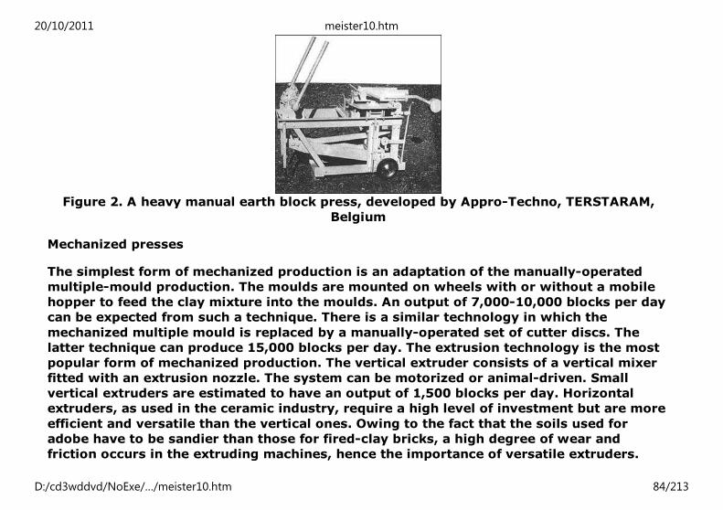
Figure 2. A heavy manual earth block press, developed by Appro-Techno, TERSTARAM,
Belgium
Mechanized presses
The simplest form of mechanized production is an adaptation of the manually-operated
multiple-mould production. The moulds are mounted on wheels with or without a mobile
hopper to feed the clay mixture into the moulds. An output of 7,000-10,000 blocks per day
can be expected from such a technique. There is a similar technology in which the
mechanized multiple mould is replaced by a manually-operated set of cutter discs. The
latter technique can produce 15,000 blocks per day. The extrusion technology is the most
popular form of mechanized production. The vertical extruder consists of a vertical mixer
fitted with an extrusion nozzle. The system can be motorized or animal-driven. Small
vertical extruders are estimated to have an output of 1,500 blocks per day. Horizontal
extruders, as used in the ceramic industry, require a high level of investment but are more
efficient and versatile than the vertical ones. Owing to the fact that the soils used for
adobe have to be sandier than those for fired-clay bricks, a high degree of wear and
friction occurs in the extruding machines, hence the importance of versatile extruders.
20/10/2011 meister10.htm
D:/cd3wddvd/NoExe/…/meister10.htm 84/213

The energy content of unstabilized manually-made soil blocks is so low as to be almost
negligible, by comparison with the energy content of fired bricks or of concrete blocks.
When machine compaction is used, the compaction energy required is still very low, but,
when the energy cost of the block press used is included the total energy consumption
rises to 50-100 MJ/ton (14).
Figure 3. A motorized earth block press, developed by CERATEC, Belgium
(c) Stabilized soil blocks
Unlike rammed earth and adobe technology, the production of compressed soil blocks
allows the use of a more flexible range of soil types because adjustments can be made in
the production process to counteract any deficiencies in the soil characteristics. However,
good quality compressed soil blocks require the use of soils containing fine gravel and
sand as well as some clay and silt to bind the sand together. At least 50 per cent of the
soil should have a grain size of less than five mm.
The production process involves pulverization of soil, screening, mixing with stabilizer and
20/10/2011 meister10.htm
D:/cd3wddvd/NoExe/…/meister10.htm 85/213
compaction. Pulverization is required for lumpy soils and can be done manually or with
machines. Screening is essential for removing large particles and organic matter,
especially if no pulverization has been done. The pulverized and screened soil - with or
without additives - should be mixed in the dry state before mixing it with water. A
conventional concrete mixer may not be useful for mixing wet soils because of the
tendency of composite materials to stick on the inside of the rotating drum and because of
the formation of lumps in the soil.
Based on extensive studies and experiments, it has been found out that blocks stabilized
with 5 per cent cement have a strength and durability comparable with ordinary clay
bricks and concrete blocks. The energy requirements for this type of blocks with only 5
per cent cement is about 150 to 300 MJ/ton. However, blocks having 10 per cent cement,
which would have adequate strength and durability, would increase the energy
requirement of soil blocks to only 300 to 500 MJ/ton, still substantially less than the
figure for any other type of alternative walling materials (4).
20/10/2011 meister10.htm
D:/cd3wddvd/NoExe/…/meister10.htm 86/213

Figure 4. A CINVA-RAM block-press. Courtesy IBEC Housing Corporation, New York
20/10/2011 meister10.htm
D:/cd3wddvd/NoExe/…/meister10.htm 87/213

Soil block presses
The mode of compaction is the key to a durable and cost-efficient compressed soil block.
The strength of a block increases with the intensity of compaction to a limit of about 4 to
10 MN/sq m, beyond which the effect is reversed. Even though the strength of a block
depends on the compressive capacity of the machine, it is equally important to ensure the
appropriate use of the machine. Blocks with different strengths could be produced by the
same machine if the production parameters are changed. Compaction machines can be
classified by the moulding pressure - measured in MN/sq m - they generate, namely (a)
low pressure: 0 to 4, (b) average pressure: 4 to 6, (c) high pressure: 6 to 10, (d) hyper-
pressure: 10 to 20, (e) mega-pressure: 20 to 40.
Some of the compaction machines available in the market were developed especially for
soil construction but others were adapted from the concrete block industry. Soil
compaction machines can be further divided into manual and motorized units. In all cases,
presses can be distinguished by their weight and their transmission principles-mechanical
or hydraulic presses.
Appropriate soil construction technology
Few programmes formulated in response to the shelter needs of low-income populations
have considered soil construction as a viable option. The legacy of unsafe and non-durable
construction, reminiscent of most existing low-income houses built of soil, has made soil
construction technology unpopular and difficult to promote, while modern soil
construction, in spite of all its improvements and advancements, poses problems of
inappropriateness in the choice of technology. In fact, in a number of cases low-income
housing constructed with modern soil technology has failed. These failures were often due
to excessive cost of production or breakdown of machinery and led to the abandonment of
entire projects. A successful soil construction programme for low-income housing should
20/10/2011 meister10.htm
D:/cd3wddvd/NoExe/…/meister10.htm 88/213

be based, first and foremost, on sound technical criteria. Thus, the following aspects need
to be taken into account:
(a) Understanding basic soil science;
(b) General design and construction considerations;
(c) Surface protection of exposed walls;
(d) Machinery for the production of soil materials;
(e) Government promotional activities.
Figure 5. Soil identification and performance tests
Soil construction requires an ability to identify soil types.
Whilst a full laboratory report would be the Ideal to aim at, this Is not always possible.
The tests outlined here can be conducted in the field with the minimum amount of equipment. They
will not give accurate proportions of the ingredients of a soil sample, but that is not always
necessary. They will give an objective result whereby it will be possible for someone to say... “that
is a sandy clay”, or... “that is an expansive clay”, etc. The ideal soil for soil construction will contain
about one third clay, one third silt and one third sand. The proportions can be slightly different, and
even totally unsuitable soil can be used, If proper precautions are taken.
Therefore, we start with a review of the equipment needed
1. EQUIPMENT
With this equipment, the following tests are designed to help you decide what
are the most important materials in your soils.
Simple field tests can be carried out using:
20/10/2011 meister10.htm
D:/cd3wddvd/NoExe/…/meister10.htm 89/213

Figure
FigureFigure
FigureFigure
FigureFigure
FigureFigure
20/10/2011 meister10.htm
D:/cd3wddvd/NoExe/…/meister10.htm 90/213

FigureFigure
2. SIEVING
Figure
One worthwhile precaution to take is to sieve all soils which are to be used in construction. This will
ensure large lumps and stones are removed, and will make remaining soil easy to use.
A useful sieve can be made from a simple wooden frame with a metal grid giving holes
approximately 3 mm to 5 mm in size.
It is, incidentally, easier to let the soil fall through the sieve than to pick the sieve up with the soil
on it!
3. CLASSIFICATION
An ideal soil type for soil construction will be in the proportions shown by the shaded area.
However, construction can go forward, even if the soil type falls outside the shaded area. It just
20/10/2011 meister10.htm
D:/cd3wddvd/NoExe/…/meister10.htm 91/213

requires extra effort or extra precautions.
Figure
Basic soil science
Often issues related to soil science are taken for granted or even ignored. An
understanding of basic soil science, however, is essential for a successful soil construction
practice. Decisions as to whether a particular soil is appropriate for construction can only
be made if the characteristics of the soil are known. This knowledge will also determine
the different aspects of the production process - whether to use adobe, rammed earth or
compressed block technology, whether stabilization is needed and what type of stabilizer
is to be used, which, if any, precautionary measures need to be taken. These
considerations are of particular importance when soil construction is used for low-income
housing because they have far reaching implications for the final cost of production. For
instance, to use excessive quantities of a costly stabilizer or even to use one which is
20/10/2011 meister10.htm
D:/cd3wddvd/NoExe/…/meister10.htm 92/213

inappropriate for a given soil composition may result in an unnecessary increase in the
cost of production.
For the purpose of low-cost construction, simple field tests can be undertaken to
determine the characteristics and suitability of the chosen soils such as the presence of
organic matter, type of soil (sandy, silty or clayey), sedimentation and shrinkage
properties.
An important component of soil science is soil stabilization. Building with soil implies a
choice between three main approaches:
(a) using the soil available on the site and adapting, as much as possible, the
functional requirements of the construction to the quality of the soil;
(b) using another soil already suitable for the requirements of project but which
has to be brought to the site from another source;
(c) modifying the local soil so that it is suited to the functional requirements of the
project. This last option implies the use of stabilizers. There are three basic types
of stabilization:
(i) Mechanical
By compacting the soil, it is possible to change its density, mechanical
strength, compressibility, permeability and porosity;
(ii) Physical
The properties of the soil can be modified by acting on its texture through,
for example, the controlled mixing of different grain fractions.
20/10/2011 meister10.htm
D:/cd3wddvd/NoExe/…/meister10.htm 93/213
(iii) Chemical
Materials or chemicals can be added to the soil to modify its properties
either by a physical and chemical reaction between grains and the additive
or by creating an impermeable layer which binds or coats the grains.
The most common stabilizers are fibers, cement, bitumen emulsion and hydrated lime.
Design and construction considerations
Appropriate design and construction practices are a prerequisite to the durability and cost
efficiency of housing for low-income groups. Low-cost soil blocks produced by
rudimentary techniques could prove durable and satisfactory if the correct design and
construction principles are adopted. Conversely, the use of high-technology and expensive
soil blocks could lead to premature deterioration and eventual failure. In this context, it
could be argued that most of the existing soil housing in low-income settlements have
high levels of deterioration mainly because of errors in design and construction
procedures rather than because of any inherent weakness of soil as a building material.
The design and construction of low-cost houses should take, at least, two items into
consideration:
(a) foundations and base courses;
(b) walls and openings.
Soil buildings are vulnerable to water penetration, especially at the ground level.
Foundations not only bear structural loads but also act as barriers to ground-water
penetration and thus prolong the existence of the building. It is important, therefore, to
provide a damp-proof course layer between the foundation and the soil block work. For
purposes of low-cost housing, simple strip foundations are suitable but stepped
foundations are more effective where sloppy grounds are encountered. Foundations can be
20/10/2011 meister10.htm
D:/cd3wddvd/NoExe/…/meister10.htm 94/213

made of ordinary concrete rubble, concrete block masonry, stone masonry and even
stabilized soil-block masonry. The base of a soil building is also vulnerable to rain water
even when a foundation is provided. Water penetration can be controlled, in areas with
high rainfall conditions, by a short-base course of impermeable material - a base course of
about two or three layers of concrete blocks, stone or fired-bricks should be adequate for
this purpose. An inexpensive alternative is to use soil blocks for the base course and
protect the exposed surface at the base of the course with a rendering such as bitumen
emulsion or cement mortar.
Rain water erosion and drainage shrinkage caused by sunshine can also affect exposed
soil walls. It is advisable, therefore, to have overhangs of at least one meter in areas of
high rainfall. Lintels are necessary above doors and windows and so is a wall plate to
distribute loads on the soil wall. The corners of soil walls are particularly prone to
deterioration from a combined effect of rain and wind. In fact, soil erosion is more
intensive at corners than at the main body of the wall. Soil erosion at comers can be
minimized by either a water-resistant rendering on the corners or by simply rounding the
corners of unprotected walls. Window sills should project a sufficient distance from the
wall to prevent the eroding effect of running water. The position of openings affects the
strength and durability of soil walls, especially where the ground is unstable. High
concentration of openings and openings near corners should be avoided.
Figure 6. Foundations
1. CONCRETE - RAFT TYPE
20/10/2011 meister10.htm
D:/cd3wddvd/NoExe/…/meister10.htm 95/213

Figure
On soil types which are soft, unstable or of changing character, or are subject to heaving, houses
can be built on a footing which floats on top of the soil like a raft on water. The raft acts as a
footing for the walls and the floor. This footing type should be surrounded by drains which will lead
water away from the house.
Mesh reinforcement for houses of different widths:
width up to 2.5 m - use 2.22 kg/m2 mesh
width 2.5 to 3.6 m - use 3.02 kg/m2 mesh
20/10/2011 meister10.htm
D:/cd3wddvd/NoExe/…/meister10.htm 96/213
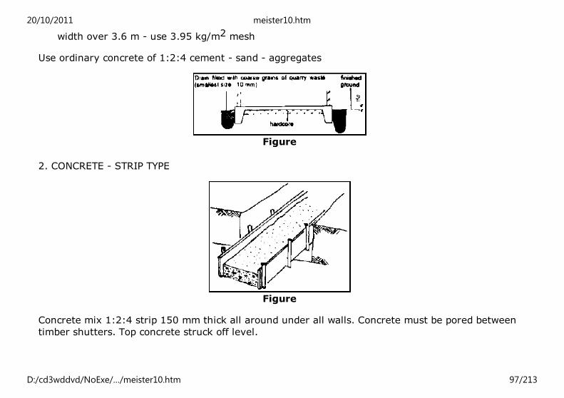
width over 3.6 m - use 3.95 kg/m2 mesh
Use ordinary concrete of 1:2:4 cement - sand - aggregates
Figure
2. CONCRETE - STRIP TYPE
Figure
Concrete mix 1:2:4 strip 150 mm thick all around under all walls. Concrete must be pored between
timber shutters. Top concrete struck off level.
20/10/2011 meister10.htm
D:/cd3wddvd/NoExe/…/meister10.htm 97/213
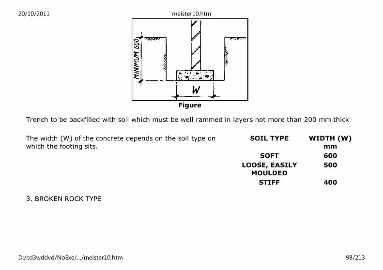
Figure
Trench to be backfilled with soil which must be well rammed in layers not more than 200 mm thick
The width (W) of the concrete depends on the soil type on
which the footing sits.
SOIL TYPE WIDTH (W)
mm
SOFT 600
LOOSE, EASILY
MOULDED
500
STIFF 400
3. BROKEN ROCK TYPE
20/10/2011 meister10.htm
D:/cd3wddvd/NoExe/…/meister10.htm 98/213

Figure
USE THIS TYPE ONLY IN STILL OR LOOSE SOIL TYPES
Rocks approximately 100-150 mm size. Each layer must be laid and rammed, and then sand must
be swept into holes. Top off with 30 mm 1:3 cement-sand mortar.
Ramming the rocks down firm Each layer of rocks must be placed carefully to fit tightly. Brush sand
over the surface.
Figure
4. STEPPED-BLOCK TYPE
In situation where concrete footings are too expansive, stabilized-soil blocks
20/10/2011 meister10.htm
D:/cd3wddvd/NoExe/…/meister10.htm 99/213

Figure
In situation where concrete footings are too expansive, stabilized-soil blocks
could SERVE as materials for footing.
Blockwork to be stepped out in three equal steps to width of foundation. Width of foundation (W) to
be the same as for concrete footing. Backfill to be brought up equally both sides of the wall. Trench
to be filled with soil which must be well rammed in layers not more than 200 mm thick.
When making a stepped blockwork footing, it is most important that each layer be staggered in its
jointing from the layer below. Below damp-proof course, blocks must be stabilized types only, or
dressed hard building stones and burnt clay bricks may be used.
Figure Figure
20/10/2011 meister10.htm
D:/cd3wddvd/NoExe/…/meister10.htm 100/213

Figure
Figure
Figure 7. Walls - Type of damp-proofing and termite-proofing
1. CONVENTIONAL BITUMINOUS
FELT DAMP-PROOF COURSE
2. ASPHALT LAYER DAMP-PROOF
COURSE
1. CONTINUOUS METAL-BARRIER
TERMITE PROOFING
FigureFigure
Figure
20/10/2011 meister10.htm
D:/cd3wddvd/NoExe/…/meister10.htm 101/213

3. DENSE REINFORCED MORTAR
LAYER DAMP-PROOF COURSE
2. STRIP METAL-BARRIER TERMITE-
PROOFING
Figure
FigureFigure
Figure 8. Foundations - Special situations
1. BUILDING ON THE SIDE OF A HILL 2. BUILDING WITH A STEPPED FOUNDATION
20/10/2011 meister10.htm
D:/cd3wddvd/NoExe/…/meister10.htm 102/213

Figure
If the depth on the uphill side is more
than 1.0 m either:
i) cut back and put in the
drainage, or
ii) use stepped foundations.
Figure
Figure
Vertical face of step must be cut straight and clean.
Concrete strip footing must be used in stepped
foundations. Make 10 cm wider than normal footings.
Figure
This is how the finished house and
ground will fit into the hillside.
Stretcher brick must span over point from concrete
footing on to wall on lower step.
20/10/2011 meister10.htm
D:/cd3wddvd/NoExe/…/meister10.htm 103/213

Figure
Backfill must than be brought up equally on both sides of
wall.
Height of step must be limited to a maximum of three
courses of bricks.
Figure
Figure 9. Floors - In-situ construction
1. ADOBE-TYPE FLOORS
Figure
If an adobe-type floor is to be laid, it must be laid in at least two
layers, each not more than 5 cm thick. Immediately after laying,
the floor should be cut into regular blocks not more than 60 cm
square. This will reduce the risk of unwanted cracks. The cuts in
higher layers should be staggered from those in LOWER layers.
Figure
Cuts in final layer must be filled with a fine adobe mortar. One
week must pass before laying successive layers. After final drying
out, the surface can be treated with a mixture of turpentine and
linseed oil, then waxed after that has dried out.
2. REINFORCED-TYPE FLOORS
Some soils where houses must be built may be unstable. They
20/10/2011 meister10.htm
D:/cd3wddvd/NoExe/…/meister10.htm 104/213

Figure
Some soils where houses must be built may be unstable. They
may heave, shrink or slip. Floors of houses in these areas must,
therefore, be reinforced. Reinforcement can be done by steel
bars.
Figure
However, bamboo poles up to 2 cm thick can be used and can be
built into the floor as it is being laid. They should be spaced 15
cm apart and should be placed in two layers right angles to each
other. Poles in one layer must be tied to poles in the other layer.
Figure
Alternatively, the poles may be laid before the floor, and the floor
mix may then be placed on to and around the reinforcement.
There should be at least 8 cm cover over the top of the
reinforcement.
3. STONE-FLAG FLOOR
Figure
In situations where stones are readily available as low-cost
materials they can be used for floors. Stone should be carefully
cut to size.
Alternatively, the poles may be laid before the floor, and the floor
mix may then be placed on to and around the reinforcement.
There should be at least 8 cm cover over the top of the
reinforcement.
20/10/2011 meister10.htm
D:/cd3wddvd/NoExe/…/meister10.htm 105/213
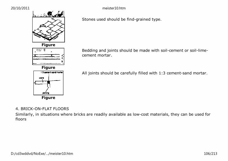
Figure
Figure
Stones used should be find-grained type.
Figure
Bedding and joints should be made with soil-cement or soil-lime-
cement mortar.
Figure
All joints should be carefully filled with 1:3 cement-sand mortar.
4. BRICK-ON-FLAT FLOORS
Similarly, in situations where bricks are readily available as low-cost materials, they can be used for
floors
20/10/2011 meister10.htm
D:/cd3wddvd/NoExe/…/meister10.htm 106/213

Figure
Figure
5. BRICK-ON-EDGE FLOORS
20/10/2011 meister10.htm
D:/cd3wddvd/NoExe/…/meister10.htm 107/213
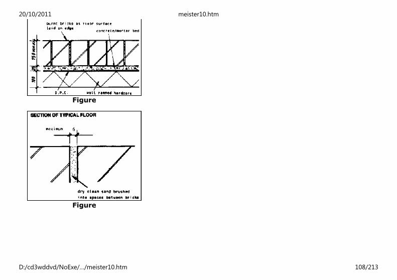
Figure
Figure
20/10/2011 meister10.htm
D:/cd3wddvd/NoExe/…/meister10.htm 108/213

Figure
NOTES
BRICKS MADE WITH A FROG MUST BE LAID WITH THE FROG
UNDERNEATH.
CEMENT-SOIL OR CEMENT-LIME-SOIL MAY BE USED FOR THE
MORTAR BED.
BRICKS MUST BE LAID WHILE THE MORTAR BED IS STILL WET.
Figure
Surface protection of buildings
Where low-strength soil blocks or unstabilized soil construction are used, the performance
of an otherwise non-durable structure can be improved by applying a surface protection.
Similarly, surface protection can be used as a technique for maintenance or upgrading
existing deteriorated soil-based dwellings. Unprotected soil walls have a fair chance of
durability in temperate climates, especially if good quality soils have been used and good
foundations and base courses have been provided. In rainy and humid regions, however,
surface protection is a basic requirement. The range of surface protection techniques for
soil construction allows for several low-cost options. There are two basic techniques for
surface protection which are relevant for low-cost soil construction: paints and rendering.
Conventional paints, distempers, slurries of lime and cement, as well as bitumen in the
form of liquid cut-back, can all be used as protective coatings on soil walls. They are
normally effective, however, when the soil walls have been carefully prepared prior to
application of the paint. For example, if lime or cement slurry is to be applied, the soil
walls must be sprayed, in advance, with water. Soil is easily the cheapest material for
20/10/2011 meister10.htm
D:/cd3wddvd/NoExe/…/meister10.htm 109/213

rendering. For this purpose, soil particle size should be two millimeters or less and
composed of one part clay and three parts sand. Soils for rendering can be stabilized with
cement, lime and bitumen. A variety of fibers, such as vegetable fibers, animal fur and
even synthetic fibers, can also be used as stabilizers.
In preparing stabilized soil renderings, cement is an effective stabilizer for sandy soils.
Mix proportions vary between 2 and 10 per cent of cement. It is also possible to improve
the water resistance of a soil-cement rendering by adding a small amount of bitumen, i.e.
2 to 4 per cent. Lime stabilizes clayey soils when at least 10 per cent is added. By adding
animal urine to the soil-lime mixture, the rendering improves shrinkage, hardness and
permeability of soil walls. Bitumen should be used for soils which are both clayey and
sandy. The proportion of bitumen is usually 2 to 6 per cent. If the bitumen is in the form of
cut-back, it should be heated to a temperature not exceeding 100°C. Alternatively,
bitumen emulsions can be used.
Machinery for production of soil materials
As indicated above, soil construction is liable to be a capital-intensive technology rather
than an energy-demanding one. The choice of soil construction technology should be
consistent with the levels of capital affordability of the respective countries. For low-cost
housing, one has to bear in mind that most developing countries operate with scarce
capital and may not have access to capital items from imported sources, even for
seemingly basic ones. Therefore, a low-cost housing scheme should aim, as much as
possible, at operating with the minimum of capital inputs.
In modern soil construction, capital items are indispensable for quality control, even in
low-cost projects. Pulverization of soils, screening, mixing, compaction and testing of raw
materials, as well as finished products, all require some form of equipment. The key issue
is to select the appropriate machinery, consistent with low-cost criteria, bearing in mind
20/10/2011 meister10.htm
D:/cd3wddvd/NoExe/…/meister10.htm 110/213

possibilities of improvizing and fabricating local equipment. For instance, in the area of
soil compaction machinery, blocks with the appropriate compressive strength for simple
low-cost houses can be produced using low technology-machines. Moreover, most of the
low-technology compaction machines can be locally fabricated in several developing
countries. This is also the case of item such as wheel barrows, measuring cans, sieves and
a host of simple field test equipment.
The scale of the technology used is a determinant of cost and appropriateness in low-cost
housing construction. Most large-scale technologies need to be imported and are subject
to uncontrollable cost escalations. In addition, repair and maintenance may present major
difficulties. Furthermore, the bulkiness of most large-scale machinery results in additional
transport costs. It is important to promote small-scale technology to counteract these
deficiencies. It must be noted that there is a distinction between the scale of output and
scale of technology and that, with appropriate organization and management, large-scale
output can be achieved with small-scale technology.
Figure 10. A mobile block press machine, developed by “Hydroform” in South Africa (a)
20/10/2011 meister10.htm
D:/cd3wddvd/NoExe/…/meister10.htm 111/213
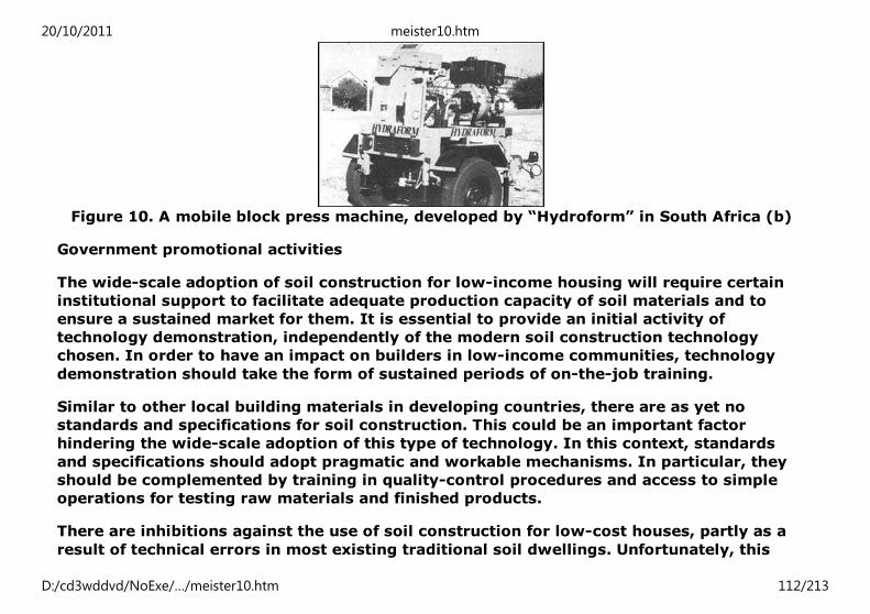
Figure 10. A mobile block press machine, developed by “Hydroform” in South Africa (b)
Government promotional activities
The wide-scale adoption of soil construction for low-income housing will require certain
institutional support to facilitate adequate production capacity of soil materials and to
ensure a sustained market for them. It is essential to provide an initial activity of
technology demonstration, independently of the modern soil construction technology
chosen. In order to have an impact on builders in low-income communities, technology
demonstration should take the form of sustained periods of on-the-job training.
Similar to other local building materials in developing countries, there are as yet no
standards and specifications for soil construction. This could be an important factor
hindering the wide-scale adoption of this type of technology. In this context, standards
and specifications should adopt pragmatic and workable mechanisms. In particular, they
should be complemented by training in quality-control procedures and access to simple
operations for testing raw materials and finished products.
There are inhibitions against the use of soil construction for low-cost houses, partly as a
result of technical errors in most existing traditional soil dwellings. Unfortunately, this
20/10/2011 meister10.htm
D:/cd3wddvd/NoExe/…/meister10.htm 112/213

stigma cannot be overcome by simply promoting technical solutions. The main approach
to this problem is for governments to actually use soil construction in on-going shelter
programmes.
Note
1.
For further details on soil construction see UNCHS (Habitat), “Earth Construction Technology”,
reference No. 21 and UNCHS (Habitat), “Journal of the Network of African Countries on Local
Building Materials and Technologies, Volume 1 No. 4 and Volume 2 No. 2”, reference No. 22.
Note
2.
This section has been produced based on a study prepared by UNCHS (Habitat).
3.2. Building stone, sand and aggregates
Building stone, sand and aggregates are the oldest, widely available and durable building
materials. These important and widely used materials, by themselves, could be considered
as no-energy materials, however, for the purpose of their processing and transportation,
some energy would be required which will make them low-energy materials. The energy
used is, principally, for mining, crushing and transporting. In the case of dimension stone,
in addition to energy requirements for quarrying and transportation, some energy is
required for cutting and polishing stones which are done in stone cutting factories with
sophisticated machinery and the use of electrical energy. In the case of sand and
aggregates, which are the main ingredients for concrete and mortar making additional
energy is used for screening them, thus, making them suitable for the purpose of their use.
In most developing countries and depending on the local circumstances most operations
related to the use of stone in building construction are carried out manually. Some values
for the energy requirements from different sources are given in table 1 below. These
values are exclusive of transporting of materials to the site and do not include the energy
of manual work involved.
20/10/2011 meister10.htm
D:/cd3wddvd/NoExe/…/meister10.htm 113/213

Table 1. Energy requirements of some stone-based materials
Material Energy requirement
(GJ/ton)
Source
Sand and aggregate:
Sand, the United Kingdom 0.03-0.3 Gartner and Rankin
Crushed aggregate, India 0.22 Rai
Building sand, India 0.015 Rai
Stone rubble, India 0.1 Rai
Building Stone:
Building stone, Kenya 0.1 Spence
3.3. Low-cost binders
Binders are important materials for any type of construction activity. They are used for
plastering walls of buildings, for making mortars in masonry and foundations for soil
stabilization, etc. Among the various types of binding materials used in construction,
Portland cement is the most attractive one because of its superior characteristics.
However, because of its high energy content and, consequently, high cost, is not
accessible to many low-income house builders. Low-cost binders, on the contrary, have
great potentiality and adequate technical characteristics to meet the requirements of low-
cost construction. The most important low-cost binders include: lime gypsum, pozzolanas
and blended cements. Lime was already discussed in the previous sections, therefore, in
the following parts, only gypsum, pozzolanas and blended cements will be briefly
discussed.
(a) Gypsum
20/10/2011 meister10.htm
D:/cd3wddvd/NoExe/…/meister10.htm 114/213
Gypsum is a traditional material made from heating mineral gypsum stones. It is used for
plastering walls, manufacturing gypsum-based plaster-boards and many other
applications. The energy requirement for manufacturing building gypsum, compared to
cement and lime is very low.
Depending on the quality of gypsum stones the heat required for gypsum kiln ranges
between 150° and 170°C, much lower than for cement (1450°C) and lime (900°C)
production.
Similar to lime production, a high proportion of total energy for gypsum production is
used in the kiln. The raw material, is calcined directly either by mixing it with the fuel, or
it is burnt indirectly by burners. Indirect heating offers better control, produces better
quality gypsum and is suitable for small-scale-operations. Most production processes in
developing countries are intermittent and not energy-efficient. Rotary kilns, however,
offer more energy efficiency but require more capital.
Comprehensive data on the energy consumption of gypsum plaster production at all scales
are not available. Some examples of the energy consumption using different kiln types and
scales of production are given in table 1. Even the least efficient processes use
substantially less energy than either cement or lime production. However, a direct
comparison between the three materials is not possible, because they all have slightly
different properties (1).
20/10/2011 meister10.htm
D:/cd3wddvd/NoExe/…/meister10.htm 115/213

Figure 1. A walled kiln for burning gypsum. Courtesy IT, U.K., Gypsum and Plaster
Figure 2. A shaft kiln with masonary cylindrical wall. Courtesy IT, U.K., Gypsum and
Plaster
20/10/2011 meister10.htm
D:/cd3wddvd/NoExe/…/meister10.htm 116/213

Figure 3. Hopper-fed furnace-heated batch kiln. Courtesy IT, U.K., Gypsum and Plaster
Table 1. Comparative energy requirements for gypsum production
Process Energy requirement
(GJ/ton)
Source of data
Large-scale production, United Kingdom 0.8 to 1.0 Coburn and others
Calcined gypsum, India 1.5 Rai
Plaster of paris, Germany 1.5 Rai
Small-scale production, North Africa 2.7 to 4.6 Coburn and others
(b) Pozzolanas
Pozzolanas are siliceous materials which can be either natural or artificial. Pozzolanas on
their own have little or no binding property, but when finely ground and mixed with lime
20/10/2011 meister10.htm
D:/cd3wddvd/NoExe/…/meister10.htm 117/213

will set and harden, in the presence of water.
The most commonly occurrences of natural pozzolanas are volcanic ashes and pumice
powder. These pozzolanas, depending on the expected strength of the mortars, can reduce
the use of lime by 20 to 30 per cent, but if mixed with cement, the substitution to cement
can even be higher. Thus, considerable amount of energy saving can be achieved through
using less cement or lime while obtaining an acceptable result.
Artificial pozzolanas are produced from a number of industrial and agricultural wastes
which are highly siliceous. These include:
(i) fly-ash obtained from coal burning power plants
(ii) ground blast furnace slags resulting from iron plants
(iii) burnt clay powder and
(iv) rice-husk ash from burning the rice husks in specially designed incinerators. As
in the case of natural pozzolanas, the artificial pozzolanas are processed and mixed
either with lime or cement to be used as binding material in low-cost construction
or soil stabilization.
20/10/2011 meister10.htm
D:/cd3wddvd/NoExe/…/meister10.htm 118/213

Figure 4. Lime sludge/rice husk balls laid out to dry. Courtesy IT, UK, Rice Husk Ash
Cement
Even though processing pozzolanas and producing them in a usable form, to be mixed
with lime or cement, requires some energy, experiment and extensive research work have
shown that the sum of energy used in this process is less than the energy used in the
substituted cement or lime. Needless to emphasis that the environmental impact of the
use of industrial and agricultural wastes is another reason which makes the use of
pozzolanas attractive.
(c) Blended cement
Manufacturing blended cement (also called pozzolanic cement) is one of the promising
trends in the reduction of energy use in construction. Blended cements are either
produced directly in cement plants (e.g. by mixing certain types of pozzolanas with
20/10/2011 meister10.htm
D:/cd3wddvd/NoExe/…/meister10.htm 119/213

cement clinkers and grinding them together) or they can be produced on site by mixing
ordinary Portland cement (OPC) with finely ground pozzolanas. In producing blended
cements, almost all types of common pozzolanas can be used. However, among the
different types of pozzolanas, furnace slag has been widely used in the process of
producing blended cement, which is very popular in both developed and developing
countries and for which relevant standards have already been established. The
replacement percentages of pozzolanas vary from 15 to 50 per cent resulting in an energy
saving of up to 40 percent. Table 2 shows some energy saving examples from India.
Blended cements can be used not only for making mortars for masonry or plastering
purposes but also for structural concrete, particularly for foundation and/or mass
concreting purposes. It can be also used in block-making for use in load and non-load
bearing walls.
Table 2. Energy-saving opportunities using pozzolanas as replacement of cement
Type of blended cement Composition
(percentage)
Energy
(kj/kg)
Saving
(percentage)
Portland burnt clay pozzolanas cement Portland cement: 75 5945
Burnt clay pozzolanas: 25 335 20
Portland fly-ash pozzolanas cement Portland cement: 75 5945
Fly-ash: 25 Nil 25
Portland blast furnace slag cement Portland cement: 60 4773
BFS: 40 Nil 40
Masonry cement Portland cement: 50 3970
Mineral tailing: 50 Nil 50
20/10/2011 meister10.htm
D:/cd3wddvd/NoExe/…/meister10.htm 120/213

Source: Government of India, “Use of energy by household and in production of
building materials”. Unpublished paper prepared for the 13th session of the
Commission on Human Settlement, Harare, May 1991.
Note: For a detailed treatment of low-cost binders, see UNCHS (Habitat), “Endogenous capacity-
building for the production of binding materials in the construction industry-Selected case
studies”, reference No. 23 and UNCHS (Habitat), Journal of the Network of African Countries
on Local Building Materials and Technologies volume 1, No. 1, 1989 and volume 2 No. 1,
1992.
Figure 5. Calcination kiln for powdery lime sludge to be used in production of blended
20/10/2011 meister10.htm
D:/cd3wddvd/NoExe/…/meister10.htm 121/213

cement
3.4. Timber and bamboo
3.4.1 TIMBER
Timber is the most important and widely accepted organic material used for centuries in
building construction and if extracted from managed forests and used in a sustainable
manner it can be used for ever. It can be used at any level of technology for a wide range
of purposes ranging from its uses in rural areas to being processed in high-tech factories
for manufacturing structural and non-structural building elements as well as furniture.
As a natural and renewable resource, it is also a very low-energy material with superior
characteristics which makes it quite attractive for many construction purposes. Various
studies have shown that even though using timber as a building material involves the use
of energy for logging, transportation, seasoning, cutting, processing etc., the sum of all
energy used in all these processes per weight basis is much less than any other energy-
intensive structural material such as steel, aluminium, concrete, bricks etc. Table 1 shows
some examples of the primary energy requirements for some timber products.
Table 1. Energy requirements fur timber production
Product Energy requirement
(GJ/ton)(GJ/m3) Source of data
Softwood framing, USAa 0.7 0.34 Stein
Timber at site, Australiaa 2.0 Lawson
Timber processing, Argentina 0.4 RaiTimber, Germany 1.04 Rai
20/10/2011 meister10.htm
D:/cd3wddvd/NoExe/…/meister10.htm 122/213

Timber, Germany 1.04 Rai
Timber (concrete formwork), UK 1.6 Haseltine
Timber products, UK 5.4 Gartner and Rankin
Particle hoard, India 3.1 Rai
Particle hoard. USAa 9.2 4.6 Stein
Plywood. USAa 13 Stein
a Includes transport to site
The advantages of timber as a low-cost construction material are first and foremost
technical. Timber, after certain processing, can be used for almost the entire structure of a
house as load bearing and non-load bearing elements. Timber has a unique combination of
both thermal efficiency and superb sound insulation qualities. It has a high ratio between
structural resistance, resilience and weight and is, therefore an excellent material to be
used in building structures in earthquake-prone areas. For example, in Southern California,
about 80 per cent of all residential buildings of up to four storey high are constructed with
timber which include: walls, floors, roofs and even outside cladding of the buildings.
In principle, production of commercially accepted timber from tropical forests can be
made sustainable, but in practice, a combination of commercial interests, lack of
information, population pressure and mismanagement is leading to a rapid loss of forests
in most worlds tropical regions.
One way of tackling the problems associated with deforestation is encouraging the use of
commercially less-accepted species (CLAS) and industrial tree plantation species (ITPS).
If properly managed and exploited, these species can serve as abundant and renewable
resources of building materials that can be afforded by the vast majority of the population.
20/10/2011 meister10.htm
D:/cd3wddvd/NoExe/…/meister10.htm 123/213

There are currently no significant examples of use of CLAS and ITPS as a walling material
or roof-cladding material in developing countries. In some cases, the wood elements are
only restricted to internal partitioning (24).
The use of CLAS and ITPS for construction, especially for walling purposes and as shingles
for roofing, is slowly showing potential in industrially-processed wood products where the
CLAS and ITPS serve as raw material. The use of wood chips, pulps and excelsior for
composite boards in some countries relies on timber species which are less suitable as
sawn wood due mainly to their irregular form. There is potential for using chips and
excelsior from CLAS and ITPS to manufacture wood-cement boards. In some countries,
where these products are on commercial sale, there is an unfavourable market trend
probably due to the unattractiveness of the finish of the boards.
The Second Consultation on the Wood and Wood Products Industry, organized jointly by
UNCHS (Habitat) and UNIDO and held in Vienna in January 1991, underscored the
importance of greater utilization, on a sustainable basis, of wood, including CLAS and
ITPS, as a renewable source of indigenous building materials in housing and construction.
The Consultation, while focusing on environmentally-sound management of forests,
devised a set of recommendations addressing the industry, governments and the
international community on ways and means for popularizing the use of CLAS and ITPS in
the construction sector (24).
Seasoning timber
Although timber is considered as being “no-energy” material, for processing purposes,
there is a need for certain amount of energy. Among the various stages of processing,
seasoning the timber, particularly, when it is done in heated kilns, requires the highest
amount of energy compared to other processing stages such as cutting, shaping,
transporting, etc.
20/10/2011 meister10.htm
D:/cd3wddvd/NoExe/…/meister10.htm 124/213

The purpose of seasoning timber is to remove the extra moisture of green timber under
controlled conditions. Timber has a tendency to change dimensions in response to
changes in moisture content, therefore, a proper seasoning bringing the timber to its final
dimensions and making it stable for use in structures is one of the most important and
energy demanding stages of timber processing.
For structural work, timber should be dried to within 5 per cent of equilibrium moisture
content (EMC). This value refers to the moisture content which would be attained in
service. EMC depends upon the relative humidity and the temperature of the surroundings
and the following may be considered a rough guide (25).
Table 2 shows some examples of EMC for various climates.
Table 2. Equivalent moisture content of timber
Region Equilibrium moisture content
(percentage)
Hot dry regions (desert, semi-desert and savannah) 10-12
Tropical highlands (above 1500m) 12-14
Tropical lowlands, rain forests 14-18
(Other climate conditions are not included)
Source: UNCHS (Habitat), reference No. 25.
Seasoning timber can be carried out in two ways, air drying and kiln seasoning.
Air drying
Green timber is stacked in open sheds using spacers made of wooden sticks for air
20/10/2011 meister10.htm
D:/cd3wddvd/NoExe/…/meister10.htm 125/213

circulation. The thickness of spaces vary between 15 mm to 40 mm depending on the
timber species and outside temperature. The stacks would be put on solid-base and raised
above the ground.
The time required for seasoning depends on the species and the climate (humidity and
temperature) of the surroundings. In tropical climates some soft woods require at least
six weeks, while denser hardwood would need 25 weeks or more.
Kiln seasoning
Green timber is placed in a kiln or a chamber in which temperature, humidity and flow of
air can be controlled. Kiln seasoning allows timber to be dried to any desired moisture
content appropriate to its end use. The technology of kiln seasoning is well advanced in
both developed and developing countries and there exist quite a number of types and
methods including special treatments of timber such as reconditioning and sterilization.
Solar seasoning
Solar seasoning is the most energy efficient method for drying timber. This method uses
the sun radiation to heat the air inside a chamber where timber is stacked. Over the past
decade, considerable research into this method has been carried out in some developing
countries such as India and Sri Lanka and in some cases it has been introduced in
commercial use. Figure 1 shows a solar kiln designed in the Central Building Research
Institute in Roorkee, India and figure 2 shows a Bangladesh kiln designed by M. A. Sattar.
It is made up of three main parts namely:
(a) solar-energy collector;
(b) seasoning chamber; and
(c) chimney.
20/10/2011 meister10.htm
D:/cd3wddvd/NoExe/…/meister10.htm 126/213

Experiments on this kiln has shown that the time taken in seasoning three different types
of wood, e.g. mango (Man giferaindica), Jamu (Eugenis jambolana) and haldu (Adina
cardifolia) from green stage to 10 per cent moisture content for a thickness of 3.75 cm
would require 17, 27 and 18 days respectively, while seasoning the same specimen under
a shed in open air would need 35, 62 and 40 days (25). The number of different designs of
solar kilns has increased rapidly in the last few years with a tendency towards better
insulated structures and more sophisticated control of humidity, venting and air
circulation (26), (27) and (28).
Figure 1. Solar kiln designed in Central Building Research Institute (CBRI), Roorkee, India.
The attached Annex presents, in a summary from, a research project carried out on solar
timber seasoning in Sri Lanka. It demonstrates the advantages and technical feasibility for
drying some secondary species of wood including the rubber and coconut wood.
20/10/2011 meister10.htm
D:/cd3wddvd/NoExe/…/meister10.htm 127/213

Figure 2. Bangladesh kiln. Courtesy TRADA and ODA, reference No. 29
Timber protection (25)
In order to protect timber against hazardous attacks such as fungi, insects and marine
borers, timber used in structural work should be treated by special preservatives. A
successful treatment of timber depends upon the type of chemical used, as well as the
type of timber and treatment. With the exception of diffusion treatment, the moisture
content of the timber to be treated should not exceed 30 per cent. The maximum
permiceable moisture content depends also to some extent upon the process, type of
preservative chemical and the kind of timber.
In general, there are three types of wood preservatives: tar oil; water-borne; and organic
solvents.
Tar-oil compounds or creosotes are suitable for exterior work, in water or in ground
contact. The principal advantages of creosotes are their high toxicity against fungi, insect
and marine borers. Tar-oil preservatives may be applied by vacuum-pressure, hot and cold
open tank, brushes, spraying or immersion. For exterior work the recommended methods
are either vacuum-pressure or hot and cold open tank.
20/10/2011 meister10.htm
D:/cd3wddvd/NoExe/…/meister10.htm 128/213

Water-borne preservatives require special methods of application to ensure deep
penetration and are not suitable for brush treatment. Contrary to tar-oil treatment the
treated timber is odourless and can be painted over when it is dry. Water-borne
preservatives are applied to seasoned timber by vacuum-pressure methods, whilst boron
compounds are applied to green timber by diffusion. They can be used in wet and dry
conditions, including ground contact.
Organic solvent preservatives are readily absorbed by the timber and so may be applied by
brush, spray or immersion. For a deeper penetration, methods such as double vacuum may
be used. They do not cause the timber to swell. Treated timber may be painted and is not
corrosive to metals.
Extensive research over the past few years, has revealed that most of the common and
commercially-produced preservatives are toxic, and hazardous to human health, even
though they are the most effective means to protect timber from all types of destructive
agents. In fact the higher the toxicity of preservatives the higher their effectiveness. As a
result of new experiments, the manufacturers of timber preservatives have developed
alternative products some of which are also suspected to be harmful and the use of a
series of preservative substances (such as aldrin, chlordane, dieldrin and some arsenic
compounds, to name a few) is officially prohibited in several countries. The use of
substances like pentachlorophenol (PCP) and lindane (gamma-hexachloro-cyclohexane or
just y-HCH) is also greatly restricted, and likely to be forbidden in due course (30).
Unfortunately, despite their high toxicity, most of these chemicals are still being officially
recommended and widely used in almost all the developing countries, a serious problem
that requires urgent attention. The main drawbacks of chemical treatment are: (30)
- Fungicides and insecticides have to be sufficiently toxic to be effective, and
cannot differentiate between harmful and harmless organisms, which are destroyed
20/10/2011 meister10.htm
D:/cd3wddvd/NoExe/…/meister10.htm 129/213

likewise. Some destructive organisms develop resistance to toxic chemicals, which
thus fail to serve their purpose, but destroy useful creatures (e.g. bees, spiders,
birds).
- The chemicals affect animals and humans by way of inhalation, skin contacts or
through contaminated food, causing various health problems, ranging from
headaches, nausea, dizziness, aggressions, depressions, rash, etc. to diseases of
the lungs, heart, liver, kidneys and other organs, malformations, paralysis and even
cancer.
- The production, application and disposal of biocides all contribute to serious
environmental pollution. The toxic chemicals and their poisonous by-products,
many of which are extremely persistent (the most well-known example being
DDT), enter the food chain and accumulate in ever increasing concentrations in the
bodies of all living organisms, most of all in human beings. The production and
handling of biocides endangers workers and users of treated products. Solar
radiation, high temperatures and humidity, atmospheric pollutants and other
factors can transform certain preservatives into other, more dangerous substances
(for instance, PCP produces dioxin, a so-called ultra-toxin).
20/10/2011 meister10.htm
D:/cd3wddvd/NoExe/…/meister10.htm 130/213

Figure 3. Preservation of timber by dip diffusion
3.4.2 BAMBOO
After timber, bamboo is the second important organic product which requires much less
energy for its processing and seasoning than timber. In fact, many researchers and
professionals call bamboo as a “no-energy” material with very good structural property to
be used in low-cost construction, particularly, in bamboo growing countries. Bamboo is a
very fast growing plant and some species can reach their full height within 6 months (up
to 35m height). However, it takes 3 to 6 years to develop adequate strength for use in
structures. There are, in principle, two main types of bamboo, namely: “Sympodial” or
clump forming bamboo, found mainly in warmer regions, and “Monopodial” or running
bamboo, found in the cooler areas.
Well-matured culms have greater resistance to deterioration than younger ones, however,
a proper preservative treatment can double or triple the resistance and the durability of
bamboo. Like the treatment of timber, chemical preservation of bamboo is very important
20/10/2011 meister10.htm
D:/cd3wddvd/NoExe/…/meister10.htm 131/213

to reduce the attacks of termites, but again most of the available chemicals are toxic and
harmful to human health and the environment. Based on extensive research, it has been
found out that preservatives derived from borax, soda, potash, wood tar, beeswax and in
seed oil are less harmful than other commercial chemicals. The effectiveness of these
preservatives are, normally, less than those poisonous chemicals, but can be equally
effective in conjunction with good building design and construction (for example,
avoidance of contact with soil, exclusion of moisture, good ventilation, accessibility for
regular checks and maintenance, etc.) (31).
The areas of application of bamboo include: frames (beams and columns), trusses for roof,
grids (spare trusses), seaffolding, fencing, bridges, etc. Sometimes, for special purposes,
full culms are halved to produce two U-shaped cross-section for using in gutters, walls,
purlins, etc. Split bamboo strips can also be used for matting and woven panels, fencing,
ornamental screens, etc. Even the bamboo fibres and chips can be used for manufacturing
fibre boards, particle boards and fibre concrete.
Even though use of bamboo, as a very low-energy and low-cost material, has considerable
advantages, it has a number of setbacks such as: (31)
•••• Low durability, especially, in moist conditions, as it is easily attacked by
biological agents, such as insects and fungus;
•••• Bamboo catches fire easily;
•••• The low compressive strength and impact resistance limit its application in
construction. Wrong handling, bad workmanship and incorrect design of bamboo
structure can lead to cracking and splitting which weaken the material and make it
more vulnerable to attack by insects and fungus. Nails cause splitting;
•••• The irregular distances between nodes, the round shape and the slight tapering of
20/10/2011 meister10.htm
D:/cd3wddvd/NoExe/…/meister10.htm 132/213

the culms towards the top end makes tight-fitting construction impossible, and
therefore, cannot replace timber in many applications;
•••• Bamboo causes greater tool wear than timber;
•••• Bamboo preservative treatments are not sufficiently well-known, especially the
high toxicity of some chemical preservatives recommended by suppliers and official
bodies.
If compared with timber, bamboo has quite a number of advantages. It is an abundantly
available material which is low-cost and renewable. Its handling and treatment can be
done with specific tools and traditional methods. Its strength characteristics, particularly
its high tensile strength makes it an ideal material for frames and roof trusses. Having
very low weight and high ductility, structure made of bamboo, if well designed and
constructed are earthquake resistant.
For example, in Costa Rica, the powerful earthquake of April 1991 which damaged many
buildings, did not affect those houses which were built in bamboo. In fact, the emergency
reconstruction programmes supported by the Government of the Netherlands after the
earthquake focussed mainly on the use of bamboo for new housing schemes. (32)
Furthermore, it is worth mentioning that based on a UNCHS (Habitat) supported project in
Costa Rica it is expected to construct some 7000 houses per year after 1995 using bamboo
as structural elements. For this purpose necessary planning and arrangements have been
put in place to plant and harvest sufficient quantities of bamboo in the country. The
expertise and experience gained by this project is now widely sought in the Latin
American region where interest in bamboo technology is steadily growing (32).
20/10/2011 meister10.htm
D:/cd3wddvd/NoExe/…/meister10.htm 133/213

Figure 4. Column placement in continuous foundation. Courtesy UNDP/UNIDO, RENAS-
BMTCS, Manila
20/10/2011 meister10.htm
D:/cd3wddvd/NoExe/…/meister10.htm 134/213

Figure 5. Column placement in square footing. Courtesy UNDP/UNIDO, RENAS-BMTCS,
Manila
20/10/2011 meister10.htm
D:/cd3wddvd/NoExe/…/meister10.htm 135/213

Figure 6. Bamboo roof trusses. Courtesy UNDP/UNIDO, RENAS-BMTCS, Manila
Home"" """"> ar.cn.de.en.es.fr.id.it.ph.po.ru.sw
Global Overview of Construction Technology Trends: Energy
Efficiency in Construction (HABITAT, 1995, 210 p.)
4. Innovative technologies related to recycling of materials
(introduction...)
4.1. Organic wastes
20/10/2011 meister10.htm
D:/cd3wddvd/NoExe/…/meister10.htm 136/213

4.2. Inorganic wastes
Global Overview of Construction Technology Trends: Energy Efficiency in Construction
(HABITAT, 1995, 210 p.)
4. Innovative technologies related to recycling of materials
USE OF ORGANIC AND INORGANIC WASTES
In the context of this section, “wastes” are meant to be “by-products” or “residues” of
organic or inorganic nature which are accumulated as a result of agricultural and
industrial processes. Organic wastes are, generally, agricultural or forestry by-products,
while inorganic wastes are mainly obtained from industrial processes.
As a result of rapid population growth and industrialization, the generation of organic and
inorganic solid wastes has increased several fold during the last few years causing
considerable disposal problems and environmental pollution. It has become common sight
to find large dumps of solid wastes near industrial units causing air, land, and water
pollution. It is for this reason that a proper use of large-scale wastes such as rice husks,
coffee hulls, fly-ash, phosphogypsum, bauxite wastes, furnace slags, etc. has become a
20/10/2011 meister10.htm
D:/cd3wddvd/NoExe/…/meister10.htm 137/213

matter of concern, as there is considerable scope for better management of these wastes.
As it was mentioned earlier, by using these wastes, particularly, in the production of
blended cements, energy savings of up to 50 per cent can be achieved which is quite
attractive. The use of some agricultural wastes such as rice husks, bagasse and coffee
hulls can also contribute directly to the energy requirements of kiln processes, thus
reducing the need for higher grade fuels. It is for these reasons that many countries have
already started taking effective measures to utilize these wastes in the building industry.
4.1. Organic wastes
Rice husk
Rice is cultivated as a major agricultural food crop in 75 countries of the world. About 400
million tons of paddy rice are produced annually in these countries. Based on various
studies and research work, it is established that 1 ton of rice husk is generated from every
5 tons of paddy; thus, there should be about 80 million tons of rice husk available annually
worldwide of which 64 million tons are produced in the Far East countries (33)
The increasing demand for rice by the growing populations in the rice-eating regions of
the world creates an upward trend in the annual production of paddy rice. Due to the
improvement in the milling process, there is also an expected increase in the amount of
rice husk to be generated. The disposal of this low value by-product-rice husk-will
continue to pose as a problem to the 75 countries where rice is grown. Apart from the
construction potentials of rice husk its conversion into ash cement is, therefore, a better
alternative to the present-day dumping and burning methods of disposing it 33. Table 1
shows rice husk availability in some African Countries.
Table 1. Rice husk availability in some African countries
Countries with 10.000 Estimated Countries with 10.000 Estimated
20/10/2011 meister10.htm
D:/cd3wddvd/NoExe/…/meister10.htm 138/213

Countries with 10.000
tons/year
(or more)
Estimated
quantity
(1.000 tons)
Countries with 10.000
tons/year
(or more)
Estimated
quantity
(1.000 tons)
Egypt 470 Zaire 49
Madagascar 422 United Rep. of Tanzania 43
Nigeria 218 Mali 25
Sierra Leone 103 Mozambique 14
Cte d’Ivoire 102 Senegal 12
Guinea 70 Ghana 12
Liberia 49 Malawi 8
Source: UNCHS (Habitat) and Commonwealth Science Council (CSC), Journal of the
Network of African Countries on Local Building Materials and Technologies Vol. 1
No. 1, April 1989
20/10/2011 meister10.htm
D:/cd3wddvd/NoExe/…/meister10.htm 139/213

Figure 1. Demonstration unit of incinerator installed in Dhaka, Bangladesh. Courtesy
UNDP/UNIDO, RENAS-BMTCS, Manila
Apart from its potential use as low grade fuel, insulation material and filler, rice husks can
be used (after having incinerated to produce reactive ash) as a pozzolana to replace,
20/10/2011 meister10.htm
D:/cd3wddvd/NoExe/…/meister10.htm 140/213

partially, cement and also to be used in block-making.
In view of its abundant availability, many research institutions have undertaken
considerable research over the last two decades, and the results and findings have been
well documented. Table 2 gives an example of results of the average compressive
strengths of mortar cubes made of Portland rice-husk ash cements.
Table 2. Average compressive strength of the RHA/OPC mortar cubes
Sample
No.
Composition of
the cementitious
material
(percentage)
Number of
specimens
tested
Age
(days)
Compressive
strength
Remarks
C1 100 OPC 30 7 12.4 Control samples 100 per cent
OPC
P/C/10 10 RHA
90 OPC
60 7 14.3 115.3 per cent of controlled
samples strength
P/C/20 20 RHA
80 OPC
60 7 12.9 104.0 per cent of controlled
samples strength
P/C/30 30 RHA
70 OPC
60 7 11.7 94.0 per cent of controlled
sample strength
P/C/40 40 RHA
60 OPC
60 7 10.5 84.7 per cent of controlled
strength
P/C/50 50 RHA
50 OPC
60 7 10.2 82.3 per cent of controlled
strength
A/L/30 30 RHA
70 Lime
90 7 8.2 Samples were at 50°C for 4 days
A/L/40 40 RHS 90 7 10.2 Strength for such accelerated
20/10/2011 meister10.htm
D:/cd3wddvd/NoExe/…/meister10.htm 141/213

A/L/40 40 RHS
60 Lime
90 7 10.2 Strength for such accelerated
curing is equivalent to the
strength of 28 days normal
curing
C1 100 OPC 30 28 17.85 Control samples 100 per cent
OPC
P/C/10 10 RHA
90 OPC
60 28 19.41 108.7 per cent of controlled
samples strength
P/C/20 20 RHA
80 OPC
60 28 16.88 94.6 per cent controlled samples
strength
P/C/30 30 RHA
70 OPC
60 28 15.33 81.1 per cent of controlled
samples strength
P/C/40 40 RHA
60 OPC
60 28 14.29 80.1 per cent of controlled
samples strength
P/C/50 50 RHA
50 OPC
60 28 12.24 68.6 per cent of controlled
samples strength
Source: UNCHS (Habitat), Endogenous Capacity Building for the Production of
Binding Materials in the Construction Industry - Selected Case Studies, reference
No. 23
Besides the use of rice-husk ash for producing blended cements and for block-making, a
recent research work has proved that rice-husk ash can be used in manufacturing sodium
silicate (waterglass) solution. Waterglass can be used as water proofing agent if applied,
as a paint to the external walls, foundation plinths, etc. It has also been used in the
manufacture of adobe blocks to increase the durability of walls. For detailed treatment of
this subject refer to the UNCHS (Habitat), Journal of the Network of African Countries on
Local Building Materials and Technologies, Volume 1 No. 1, 1989 and Volume 2. No. 1 June
20/10/2011 meister10.htm
D:/cd3wddvd/NoExe/…/meister10.htm 142/213

1992.
Natural fibres
Natural fibres such as asbestos, sisal, hemp, kenaf, coir, bamboo, and begasse are natural
products, which, with no or very little processing, can be used in building materials. The
most significant use of these fibres is in the production of roofing tiles or sheets - fibre
concrete roofing (FCR). Among the above mentioned fibres, asbestos is the most
attractive one, which until recently was extensively used for producing corrugated and flat
roofing sheets and tiles, pipes etc.
However, the serious health risks (lung cancer) associated with mining and processing
asbestos have led to the gradual abandoning of this material and replacing it with other
fibres.
In the absence of asbestos, other fibres such as sisal, coir (coconut fibre), Jute etc. are
attracting more attention in the FCR technology and among them the sisal has proved to
be the most suitable one for small-scale FCR technology. Fibres are chopped to lengths of
15 to 40 mm and added to a mortar of cement sand. A 6 to 10 mm thick layer is laid onto a
flat surface for being vibrated and then placed on a mould (corrugated) for drying. After
drying, tiles are removed from the mould and water cured for at least 2 weeks.
A high proportion of energy required for the manufacture of FCR tiles is the amount of
energy which is embodied in the cement used. The attractiveness of FCR-tiles, vis-a-vis
concrete tiles, obviously lies in its thickness. An FCR-tile has an average thickness of 7
mm, whereas a concrete rooftile should be at least 12 mm thick. Table 3 shows some
comparative energy requirements of four common roofing elements. As it can be seen, a
standard concrete roof tile requires about 60 per cent more energy than FCR tile and a
corrugated-iron sheet would require almost 13 times more energy than FCR-tiles to cover
the same roof area.
20/10/2011 meister10.htm
D:/cd3wddvd/NoExe/…/meister10.htm 143/213

Table 3. Comparative energy requirements of alternative roofing assemblies for a pitched
roof
Roof assembly Embodied energy requirements
(MJ/m2)
Corrugated-iron sheets on timber 605
Clay tiles on timber 158
Concrete tiles (12.5 mm) 72
Fibre-concrete tiles (7 mm) 46
Source: UNCHS (Habitat), Development of National Technological Capacity for
Environmentally-Sound Construction, reference No. 34
Coconut wastes include fresh husks, coconut shells and waste from the coir industry. The
husk consist of 15 - 35 cm long fibres (about 60 per cent of husk), with high tensile
strength, which is affected by moisture. The fibres, and more so the pith (soft cork-like
material), are chemically reactive, as along as they are kept dry. During the retting
process (softening by soaking in water) they become inert. The difference in reactivity
between retted and fresh husks necessitates different methods of conversion into building
materials.
Unretted husks, hot-pressed (at 150°C, 1 MP a pressure for 15 to 25 minutes) without any
additives, produce strong particle boards. Unretted pith, obtained by defibrating mature
husks, hot-pressed without additives, produces strong, moisture resistant boards. Lighter,
resilient boards are made in the same way, but with addition of retted pith (low density,
highly-elastic granular material)
The incineration of unretted pith produces an ash, which has pozzolanic characteristics,
20/10/2011 meister10.htm
D:/cd3wddvd/NoExe/…/meister10.htm 144/213

similar to those of rice husk ash, and can be used for making lime-pozzolana binders.
Retted pith mixed with cashew-nut shell liquid resin (rubbery substance) produces an
expansion joint filler, which is resistant to temperature and moisture fluctuations and to
insect and fungal attack. Its granules as an aggregate in concrete are useful for thermal
insulation
Unretted fibres, mixed with paraffin wax and hot-pressed, make strong and flexible
hardboards (fibres boards).
Coir shearing waste, containing fibre, pith and dust, bonded with an adhesive, produces
particle boards with an attractive mottled appearance.
Coir waste, mixed with Portland cement and moulded under compression, produces large
corrugated roofing sheets. (This process, developed at CBRI, Roorkee, requires a hydraulic
press and drag mould, together with a set of forms, in which the cast sheets are kept
pressed for 4 hours, before demoulding and curing).
Coconut shell chips and conventional adhesives make good quality particle boards.
Coconut shell tar, obtained during the destructive distillation of the shell, is slightly
viscous liquid with anti-microbial properties(35).
4.2. Inorganic wastes
As indicated earlier, inorganic wastes are originated mainly from industrial processes.
Inorganic wastes with adequate technical and economic potential to be used in building
industry include:
(i) Fly-ash generated from coal burning power plants;
20/10/2011 meister10.htm
D:/cd3wddvd/NoExe/…/meister10.htm 145/213

(ii) Steel and blast furnace slag generated from iron and steel producing plants;
(hi) Phosphogypsum generated from phosphoric acid, ammonium phosphate and
hydrofluoric acid plants;
(iv) Red mud generated during extraction of non ferros metals such as aluminium
(bauxite waste) or copper; and
(v) Lime sludge generated from fertilizer plants, sugar and paper factories,
tanneries, soda-ash and calcium carbide industries.
Table 4 shows sources, quantities and areas of application of some industrial wastes in
India.
Table 4. Sources, quantities and areas of application of industrial wastes.
Item Source Qty
Available
in
M.T./Yr.
Application as Building Material
Flyash Thermal
Power
Stations
40.00 Portland Pozzolana Cement, Bricks, Lime Pozzolana
Mixture, Lightweight Aggregate, Cellular Concrete
Blast Furnace
Slag
Steel Plants 7.41 Production of Portland Blast Furnace Cement, Super
Sulphated Cement, as an aggregate in concrete, as
substitute for sand, lightweight concrete
Cinder Thermal
Power
Stations and
3.00 Manufacture of lime cinder mortar, production of
concrete building blocks, production of bricks from black
cotton soil
20/10/2011 meister10.htm
D:/cd3wddvd/NoExe/…/meister10.htm 146/213

RailwaysCoal Washery
Waste
Coal Mines 3.00 Manufacture of bricks, tiles, lightweight aggregates, fuel
substitute in the burning of bricks
Copper Mine
Tailing
Copper Mines 0.55 For manufacture of stabilized and high stress bricks,
cellular concrete and masonry cement
Gypsum Mine
Waste
Gypsum Mines 1.50 Gypsum building plaster, ready-made plaster with lime
Iron Tailing Iron Ore
Mines
11.25 For making stabilized and burnt clay building bricks,
high strength bricks
Kiln Dust Cement Plant 2.00 In the cement industry, as a hydraulic binder
Lime Stone
Quarry
Lime Stone
Quarry
50.00 For production of Masonry cement and activated lime
pozzolana mixture
Lime Sludge Sugar, Paper,
Fertilizer,
Calcium
Carbide
Industries
4.80 For the manufacture of portland cement, masonry
cement, sand lime bricks, building lime pozzolana
mixture
Paper Waste Paper, city
garbage
For manufacture of pitch fibre pipes, Asphaltic
corrugated Roofing sheets
Phosphogypsum Phosphoric
Acid,
Ammonium
Phosphate,
Hydrochloric
Acid
Industries
11.00 For making Gypsum Plaster, Fibrous Gypsum Boards and
blocks, cement clinker, as a solid retarder and for
making super sulphate cement
Red mud Aluminium 2.00 For production of building bricks and tiles, lightweight
20/10/2011 meister10.htm
D:/cd3wddvd/NoExe/…/meister10.htm 147/213
Red mud Aluminium
Extraction
Plant
2.00 For production of building bricks and tiles, lightweight
structural blocks, roofing sheets and as an additive to
concrete
Waste Glass Glass Plant In the manufacture of Massic and glaced lightweight
aggregate, brick making
Source: Government of India, Building Materials and Technology Promotion Council
(BMTPC), India, 1994, reference No. 36
In the following section attempt is made to describe some technologies related to the use
of major agricultural and industrial wastes developed in India. Most of these technologies
have been tested in field conditions and a large number of buildings have been put up by
housing agencies in different parts of India using these new materials. For some of these
new technologies, materials and components, standard and specification have already
been formulated and have also been codified by BIS (36).
Fly-ash-sand-lime bricks (36)
Fly-ash-sand-lime bricks can be used as an alternative material for burnt clay bricks which
is one of the important building materials used for construction of housing and buildings.
Good quality and high strength bricks can be produced from fly-ash sand and lime as
binder. The mixture of fly-ash sand or bottom ash and binder in suitable proportion is
moulded into bricks under pressure which is further cured by autoclaving. The fly-ash
building bricks are usable in all types of brick masonry works and can substitute the
conventional burnt clay bricks in nearly all application. The quality of fly-ash bricks are
found to be superior to conventional burnt clay bricks in some respects such as water
absorption, crushing strength etc. The bricks are also lighter compared to burnt clay
bricks.
20/10/2011 meister10.htm
D:/cd3wddvd/NoExe/…/meister10.htm 148/213

Advantages of fly ash-sand-lime bricks over burnt-clay bricks are related to:
1. Lower mortar required in construction;
2. Plastering on outside wall eliminated;
3. More resistance to salinity and water.
Figure 1. The process of producing fly-ash-lime-brick. Courtesy BMTPC, India (a)
20/10/2011 meister10.htm
D:/cd3wddvd/NoExe/…/meister10.htm 149/213

Figure 1. The process of producing fly-ash-lime-brick. Courtesy BMTPC, India (b)
20/10/2011 meister10.htm
D:/cd3wddvd/NoExe/…/meister10.htm 150/213
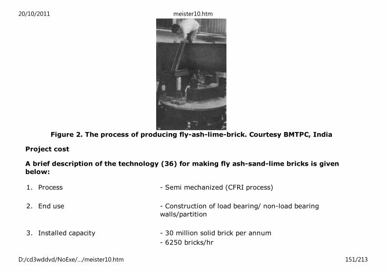
Figure 2. The process of producing fly-ash-lime-brick. Courtesy BMTPC, India
Project cost
A brief description of the technology (36) for making fly ash-sand-lime bricks is given
below:
1. Process - Semi mechanized (CFRI process)
2. End use - Construction of load bearing/ non-load bearing
walls/partition
3. Installed capacity - 30 million solid brick per annum
- 6250 bricks/hr
20/10/2011 meister10.htm
D:/cd3wddvd/NoExe/…/meister10.htm 151/213

4. Shift per day - 2 (300 working days per year)
5. Capacity utilization(expected) - 80 per cent
6. Saleable products - 24 million solid bricks
7. Land area - Total = 15000m2
Covered = 2500 m2
8. Fixed capital - (i) Land and Building -
Rs 2,1 million
(ii) Infrastructure -
Rs 0.6 million
(iii) Plant and Equipment -
Rs 15,0 million
9. Working capital - Rs 3,080 million
10. Preliminary and preoperative
expenses
- Rs 0.56 million
Total investment - Rs 21,34 million
11.Manpower
20/10/2011 meister10.htm
D:/cd3wddvd/NoExe/…/meister10.htm 152/213

11.Manpower
Managerial - 16
Technical - T12
Others - 30
12. Inputs (per 1000 nos. of bricks)
(a) Raw materials
Fly ash - 2880 Kg
Lime - 280 Kg
Sand - 432 Kg
(b) Chemical accelerator - 26 Kg
(c) Process water - 300 Lts
(d) Fuel-coal - 66 Kg
(e) Electrical energy - 50 kwh
13. Equipment/Machinery
(i) Hydraulic press
(ii) Boilers
(iii) Auto-clave curing chambers
(iv) Pulverizer
(v) Mixers
(vi) Electrical hoists with monorail
(vii) Automatic tipping type buckets
(viii) Portable belt conveyers
(ix) Winch-based scrapping hauler mechanism
20/10/2011 meister10.htm
D:/cd3wddvd/NoExe/…/meister10.htm 153/213

(x) Handling items like wheel barrows, curing trolleys, transfer cars, cycle carts etc.
14. Process outline
The fly ash, sand and lime with a small quantity of a chemical accelerator in a derived
proportion is mixed dry in a mixer. In the second stage about 8 to 10 per cent water, 0.2 per
cent chemical accelerator are added and is mixed thoroughly. The mix is then subjected to a
pressure of 250 kg/cm2 in suitable hydraulic press. The green bricks are then exposed to
natural drying for about 48 hours, followed by curing in autoclave.
15. Properties
(i) Size - 230 × 11 Ox 70 mm
(ii) Colour - Cement gray
(iii) Bulk density - 1550 kg/m3
(iv) Unit weight - 3.0 - 3.2 kg
(v) Water absorption - 15 - 20 per cent
(vi) Crushing strength - 100-120 kg/cm2
(vii) Free-lime content - Less than 0.2 per cent
16. BIS standard
IS - 12984 - 1990
17. Advantages
(a) Uniform size, require less quantity cement mortar.
(b) Can be used as facing bricks without any external plastering.
(c) Lower bulk density.
20/10/2011 meister10.htm
D:/cd3wddvd/NoExe/…/meister10.htm 154/213

(c) Lower bulk density.
(d) More resistant to salinity and water seepage.
(e) Utilization of waste and conservation of soils
(f) Saving in fuel.
18. Profitability
(i) Estimated cost of production - Rs 760/1000
(ii) Estimated sale price - Rs 950/1000
(iii) Total sale proceeds/annum - Rs 22.8 million
(iv) Break even point - 44.18 per cent
(v) Gross annual profit - Rs 4.56 million
(vi)Percentage return on capital - 21.3 per cent
19.Market
Within 50 kms radius from location of the plant.
20. Source of Technology
(i) Indigenous: CFRI, NRDC, CBRI, NTPC. NLC, NCB, BMTPC
(ii) Foreign: The United Kingdom, West Germany, Sweden, Denmark, Poland, Netherlands,
China, France, former Czechoslovakia.
21. Consultant
BMTPC, NRDC, CFRI, CBRI, NLC, M/s Development Alternatives, NCB
22. Information and Guidance
BMTPC
20/10/2011 meister10.htm
D:/cd3wddvd/NoExe/…/meister10.htm 155/213

BMTPC
Cellular concrete components (36)
With the increasing multistoreyed construction, the need for reduction in dead loads on
the structure is being increasingly recognized. One of the materials which can be used for
this purpose in load bearing construction is aerated concrete or cellular concrete blocks
and slabs.
The manufacture of Cellular Concrete involves mainly:
(i) Mixing of various raw materials in the mixer in predefined proportions;
(ii) Setting the mineral materials in the moulds;
(iii) Cutting the set cellular concrete to the desired sizes and conveying the cut
concrete to the autoclave for curing;
(iv) Autoclaving the cellular concrete in the autoclave for 14 to 18 hours at
temperature of 185°C under pressure of 10 to 12 kg/cm.
Aerated concrete is a light weight material used for masonry and for roofing as a
composite construction with concrete. Maximum quantity of fly ash to the tune of 80 per
cent by weight of the end product can be used in the production of aerated concrete. Using
fly ash will not only reduce the cost of production in respect of power consumption for
grinding but also will reduce the quantity of binder and solves the problem of disposal of
fly ash at the power station.
Besides utilisation of fly ash, the production and use of aerated concrete has several
advantages:
20/10/2011 meister10.htm
D:/cd3wddvd/NoExe/…/meister10.htm 156/213

1. Fifty per cent saving in construction time in case of aerated concrete block
masonry walls as compared to brick masonry work;
2. Eighty per cent saving in consumption of mortars;
3. Aerated concrete requires only 20 per cent of coal in manufacturing process as
compared to the requirement of coal for brick-burning;
4. Saving of agricultural land used for brick making and recycling of waste;
5. In reinforced concrete frame structured multi-storeyed buildings the use of
aerated concrete in place of bricks will reduce the dead load of the buildings
considerably thereby effecting considerable saving of steel and cement;
6. Saving of 80 per cent of water required at the construction site;
7. Better thermal insulation and sound absorption properly as compared with brick
work.
20/10/2011 meister10.htm
D:/cd3wddvd/NoExe/…/meister10.htm 157/213
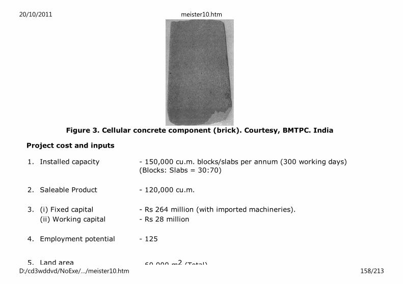
Figure 3. Cellular concrete component (brick). Courtesy, BMTPC. India
Project cost and inputs
1. Installed capacity - 150,000 cu.m. blocks/slabs per annum (300 working days)
(Blocks: Slabs = 30:70)
2. Saleable Product - 120,000 cu.m.
3. (i) Fixed capital - Rs 264 million (with imported machineries).
(ii) Working capital - Rs 28 million
4. Employment potential - 125
5. Land area - 60,000 m2 (Total)
20/10/2011 meister10.htm
D:/cd3wddvd/NoExe/…/meister10.htm 158/213

5. Land area - 60,000 m2 (Total)- 15,000 m2 (Covered)
6. Manpower - Managerial - 45
- Technical - 50
- Others - 30
7. Raw material and input (per 0.15 million cu. m of product)
(i) Fly Ash - 49,500 tons
(ii) Sand - 21.000 tons
(iii) Lime - 12,000 tons
(iv) Al-Powder - 75 tons
(v) Steel - 900 tons
8. Annual (average) cost of
production
- Rs 118.90 million
9. Sale proceeds - Rs 177.20 million
10.Gross annual income - Rs 58.40 million
11. Return on investment - 20.28 per cent
12. Break even point - 66.7 per cent
Properties
20/10/2011 meister10.htm
D:/cd3wddvd/NoExe/…/meister10.htm 159/213

(i) Sizes: For block - 50-62 × 25 × 10 to 30 cm
For slab - 600 × 50-62 × 10 to 30 cm
(ii) Colour - Grey white to white
(iii) Dry density - 600 to 750 kg/m3
(iv) Compressive strength - 2.5 to 7.5 N/m2
(v) Thermal conductivity - 0.15 to 0.27 kcal/sq.m.h
(vi)Water absorption - Not exceeding 45 per cent by volume in 48 hours
Plant and equipment
(i) Filter for silos*
(ii) Mixing equipment*
(iii) Moulding equipment**
(iv) Cutting and unloading equipment**
(v) Storage equipment*
(vi) Milling plant*
(vii) Sand milling and slurry preparation equipment**
(viii) Handling and storage equipment*
* May be procured locally
** To be imported
20/10/2011 meister10.htm
D:/cd3wddvd/NoExe/…/meister10.htm 160/213

Figure 4. Clay-fly-ash burnt brick. Courtesy BMTPC, India (a)
Figure 4. Clay-fly-ash burnt brick. Courtesy BMTPC, India (b)
Additional information
1. Market-Cities with major construction activities
2. Source of Technology-CBRI, BILT, Y-Tong (Germany), Polymexcekov (Poland),
Siporex (Sweden)
3. Information/guidance-BMTPC, CBRI
20/10/2011 meister10.htm
D:/cd3wddvd/NoExe/…/meister10.htm 161/213

Clay fly-ash burnt bricks (36)
The process involves mixing of 30 to 60 per cent of fly ash with moderately plastic to
highly plastic clays, depending upon the quality of both fly ash and clays, followed by
mixing with water, moulding, drying and firing of bricks in the usual way.
The clay bonded fly-ash bricks can be manufactured by hand moulding or by semi-
mechanized process using extrusion machine. The other operations are similar to that of
manufacturing process of burnt-clay bricks. Firing of the green bricks is carried out in
continuous type Bulls trench kiln at temperature of 950 to 1050°C.
Fly ash generally contains 5 to 6 per cent of unburnt carbon. Incorporation of fly ash,
therefore, results into a better burnt product together with an economy in fuel
consumption. It has been experimentally verified that saving of about five tones of coal
per 100,000 bricks could be achieved by mixing 40 per cent fly ash by volume with the
clay for making bricks. Other advantages of clay fly-ash bricks are reduction in the drying
shrinkage and about 15 to 25 per cent of the weight of the bricks with better thermal
insulation. The properties of bricks are not affected by mixing fly ash with the clay and the
bricks can be used for load bearing as well as non-load bearing walls.
Project cost and inputs (Manual method)
1. Installed capacity - 7.2 million bricks/annum (300 working days)
2. Saleable product - 6.12 million
3. Capital
(i) Fixed capital - Rs 294,000 (For manual operation)
(ii) Working capital -Rs 661,000
20/10/2011 meister10.htm
D:/cd3wddvd/NoExe/…/meister10.htm 162/213

(ii) Working capital -Rs 661,000
4. Employment potential - 146
5. Raw material and inputs (for 100,000 bricks)
(i) Clay - 280 tons
(ii) Flay ash - 50 tons
(iii) Sand - 200 tons
(iv) Fuel-coal - 14 tons
(v) Process water - 1000 Lit
(iv) Electricity - 50 kwh
6. Annual cost of production - Rs 4,5 million
7. Gross annual income(sale) - Rs 5,5 million
8. Return on investment - 38.53 per cent
9. Break even point - 59.91 per cent
Plant and equipment
(i) Moulds
(ii) Double shaft mixer/blender for mechanical process
(iii) Extrusion machine
(iv) Bull’s Trench Kiln/High draught kiln
20/10/2011 meister10.htm
D:/cd3wddvd/NoExe/…/meister10.htm 163/213

(iv) Bull’s Trench Kiln/High draught kiln
(v) Kiln equipment
(vi) Tube well
(vii) Electrical equipment/fittings
(viii)Water pipes and fittings
Properties
(i) Size - 19 × 9 × 9 cm or 230 × 110 × 70 mm
(ii) Colour - Red
(iii) Bulk density - 1700 to 1900 kg/m3
(iv)Water absorption - 12 to 18 per cent
(v) Unit weight - 2.5 to 3 kg
(iv) Crushing strength - 75 to 100 kg/cm2
Additional information
1. Source of technology-CBRI, Roorkee; CPRI, Bangalore, India
2. Information and guidance-BMTPC, NRDC, CBRI, CPRI
Phosphogypsum-based building materials (36)
Phosphogypsum is generated as a by-product in the manufacture of phosphoric acid
fertilizer industry by the interaction of ground phosphate rock with sulphuric acid. For
every ton of P2O5 produced as phosphoric acid about 4 to 5 tons of phosphogypsum
containing 10 to 40 per cent free moisture is obtained. It poses a problem in disposal and
causes pollution. At present, small quantities are being used as retarder in the
manufacture of cement, soil amendment and ammonium sulphate fertilizer etc.
20/10/2011 meister10.htm
D:/cd3wddvd/NoExe/…/meister10.htm 164/213

Phosphogypsum contains impurities of phosphates, fluorides, organic matter, alkalies etc.
which adversely affect the setting and development of strength of plasters/cements
produced from this. For effective utilization of phosphogypsum, it is essential to make
them innocuous to enable proper and effective utilization of phosphogypsum in
manufacture of building materials.
Advantages of utilization of phosphogypsum as a building materials and components:
(i) Conservation of clay used for agriculture purposes;
(ii) Conservation of scarce and costly materials like steel, cement and timber;
(iii) Low energy requirement for production of gypsum panel;
(iv) Utilization of industrial wastes;
(v) Environmental pollution control and reduction of disposal cost.
Building materials and components from phosphogypsum:
(a) Gypsum plaster;
(b) Gypsum ceiling tiles;
(c) Gypsum board;
(d) Gypsum panels;
(e) Gypsum marbles/blocks.
Project cost
1. Installed capacity - 7.5 million sq.m. Plaster board or equivalent
2. Investment - (a) Land and building Rs. 13,2 million
- (b) Plant and equipment Rs. 85 million
- (c) Infrastructure Rs. 23,3 million
20/10/2011 meister10.htm
D:/cd3wddvd/NoExe/…/meister10.htm 165/213

3. Technical know-how fees - Rs 25,0 million
4. Training and expenses on foreign technicians - 4,5 million
5. Preliminary and pre-operative expenses - Rs 19,2 million
6.Working capital - Rs 8,6 million
7. Contingencies - Rs 5,7 million
Total investment - Rs 184,5 million
Inputs
(i) Phosphogypsum- 250 tons/day (dry form)
(ii) Lime - 7.90 tons/day
(iii) Additives - 156 tpa
(iv) Pigments - 296 tpa
(v) Glass fibre - 8.20 tpa
(vi) Power - 20 million Kwh/annum
(vii) Water - As per requirement
Manpower
Managerial - 17
Technical - 38
Others - 158
20/10/2011 meister10.htm
D:/cd3wddvd/NoExe/…/meister10.htm 166/213

Others - 158
Machinery and equipment
(i) Cyclone separator
(ii) Vacuum filter
(iii) Rotary feeder
(iv) Mixer
(v) Screw conveyer
(vi) Moulds
(vii) Block making machine
(viii) Panel making machine
(ix) Mill
(x) Silos for storage
(xi) Materials handling equipment
(xii) Workshop equipment
(xiii) Purification/calcination plant
Additional information
1. Market Urban centres
2. Source of technology CBRI, IDL-Salzbau, Germany
3. Information/guidance BMPTC, HUDCO, NHB, SIDBI, SICOM, State financial
corporations
20/10/2011 meister10.htm
D:/cd3wddvd/NoExe/…/meister10.htm 167/213

Figure 5. Phosphogypsum-based boards. Courtesy BMTPC, India
Concrete fibre roofing sheets (36)
Coir waste, wood wool or sisal fibre can be utilized in combination with cement as a
binder for production of corrugated or plain roofing sheets.
Shearing waste (baby fibre) and coconut pith account for a large amount of agro-
industrial wastes. Unlike other cellulosic materials, coconut fibre is free from water
soluble polyphenols and makes a strong board with ordinary Portland cement as binder.
Wood wool used largely as packing material is obtained mostly from soft-wood such as
‘fir’, ‘chir’, ‘kail’, ‘dodar’ which yields good quality fibre of suitable length and width. Sisal
fibre is another suitable fibre available from sisal plant and are being extensively used in
many countries for making board and roofing sheets.
For manufacturing corrugated sheets, fibre is soaked in water for sometime and then
mixed with cement thoroughly. The cement coated mixed stuff is uniformly spread on the
drag mould and is pressed by hydraulic press. The wedged mould assembly is then rolled
out of the press and is cured for 3 to 4 hours in the curing yard. Water proofing paint is
applied on top side of the sheets after de-moulding.
20/10/2011 meister10.htm
D:/cd3wddvd/NoExe/…/meister10.htm 168/213
Salient characteristics of concrete fibre roofing:
1. Coir fibre/wood wool corrugated sheets require 30 per cent less cement as
compared to asbestos cement sheet;
2. The sheets are light and can be carried over hilly and rough roads without any
breakage;
3. The sheets are strong and possess good bending strength. A man can safely walk
over them;
4. The sheets possess good thermal insulation and are expected to provide greater
comfort in tropics as compared to AC/CGI sheets;
5. Their preparation needs neither heavy machinery nor high capital investment.
The sheets are 50 per cent cheaper than AC/CGI sheets;
6. These can be laid on roofs like AC/CGI sheets;
7. The roofs made do not require any further finishing or waterproofing treatment.
Project cost and inputs
1. Installed capacity - 30,000 sheets/ year of size 2 m × 1 m × 7 mm
2. Saleable Product - 24,000 sheets/year
3. Capital
(i) Fixed capital - Rs 2,66 million
(ii) Working capital - Rs 0.6 million
20/10/2011 meister10.htm
D:/cd3wddvd/NoExe/…/meister10.htm 169/213

(ii) Working capital - Rs 0.6 million
4. Employment potential - 28 persons
5. Raw material and inputs
(i) Cement
(ii) Coir waste/sisal fibre/wood-wool
(iii) Additive
(iv) Power
(v) Water
6. Cost of production - Rs. 127/sheet
7. Selling price - Rs. 165/sheet
8. Gross annual profit - Rs. 0.912 million
9. Percentage return on Investment (before tax) - 28 per cent
10. Break even point - 58 per cent
Technical properties
(i) Pitch of corrugation, mm. - 150
(ii) Depth of corrugation, mm. - 55
(iii) Length of the sheet, m. - 1.5 to 2.0
20/10/2011 meister10.htm
D:/cd3wddvd/NoExe/…/meister10.htm 170/213

(iii) Length of the sheet, m. - 1.5 to 2.0
(iv) Width, m. - 1.0
(v) Thickness, mm. - 7
(vi) Weight kg/sq. m. -11.0 to 12.0
(vii) Water permeability through the coated side - Nil
(viii)Water absorption in 24 hours, per cent at 250C -
(ix) Breaking load, kg/cm
(a) at 1m span - 2.5 to 2.7
(b) at 50 to 60 cm span - 5.0
(x) Thermal insulation, k Cal cm/m0h0c - 0.09
(xi) Fire resistance - Very good
Addition information
1. Market-Rural and Urban areas
2. Source of technology-CBRI, RRI, (Bhopal), Development Alternatives
3. Information/guidance-BMTPC, CBRI, NRDC
20/10/2011 meister10.htm
D:/cd3wddvd/NoExe/…/meister10.htm 171/213

Figure 6. Fibre concrete roofing sheets. Courtesy BMTPC, India (a)
Figure 6. Fibre concrete roofing sheets. Courtesy BMTPC, India (b)
Aluminium red-mud bricks (36)
Aluminium red mud or bauxite waste is a material obtained in large quantities from the
aluminium producing plants. The huge reserves of about 250 million tons of bauxite in
India suggest a manifold expansion of aluminium industry in future. Thus, alumina red
mud is going to create serious problems due to pollution and indiscriminate disposal in
the near future.
The physical properties of red mud like colloidal nature of particles, plasticity, water
absorption and mouldability and chemical composition showing the presence of alumina,
iron oxide and fluxes indicate the suitability of this material to be used in manufacturing
building brick (or flooring tiles).
To reduce transportation costs, manufacturing facilities have to be set up near the
aluminium plant where red mud and clay are easily available. In calculating the cost of
20/10/2011 meister10.htm
D:/cd3wddvd/NoExe/…/meister10.htm 172/213

production, two possibilities have been considered. In the first instance, the kiln is
situated near the red mud storage tank from where red mud slurry directly reaches
through drains or pipes in the clay pits and is mixed with the clay manually. In the second
instance the kiln is far away from the storage tank and red mud is to be transported by
trunks in lump form to the kiln site situated at about 1 km. Here the lumps are mixed with
clay in a mechanical pan mill grinder. This mix, after wetting can be either used for making
hand moulded bricks or can be extruded by a pugmill for making wire cut bricks. The
process is not much different than that adopted for making normal clay bricks. However,
red mud brick slurry or lumps are to be mixed with clay thoroughly in clay pits or in a
mechanically-operated pan mill grinder.
Advantages
(a) When the clay used is inferior in quality the addition of red mud improves the
quality of bricks product;
(b) Red mud gives the bricks pale brown, orange or golden yellow colour
depending upon composition of raw material and firing temperature. They have,
therefore, good architectural value as facing bricks;
(c) The presence of 4 to 5 per cent of alkali in red mud provides good fluxing action
resulting into good plasticity and better bond in the bricks.
Production rate
(a) 36,000 bricks per day of three shifts
(b) Size: 22.5 × 11.25 × 7.5 cm
Land and building requirements
20/10/2011 meister10.htm
D:/cd3wddvd/NoExe/…/meister10.htm 173/213

1. Land - 8.25 acres
2. Shed - 100 sq.m.
3. Building Office cum-store - 100 sq.m.
Machinery and equipment
1.Mixer - 1
2. Pug mill and extruder - 1
3. Tubewell - 1
4. Pan mill - 1
5.Weigh batcher - 2
6. Handling equipment - 3-4
Raw materials (per annum)
1. Clay -0.75 acre (18000 m3)
2. Alumima red mud - 13,500 tons
Utilities
1. Electrical power - 86,400 kwh
2. Coal - 1152 tons
3.Water - 7200 kl
20/10/2011 meister10.htm
D:/cd3wddvd/NoExe/…/meister10.htm 174/213
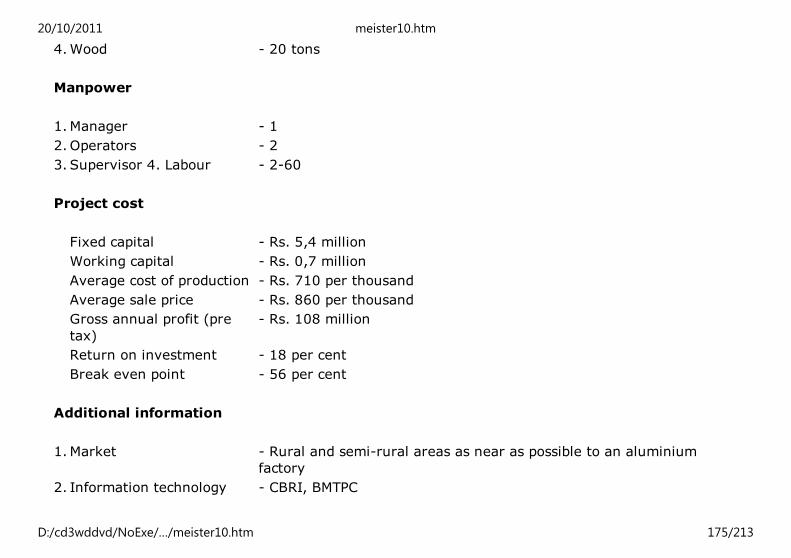
3.Water - 7200 kl4.Wood - 20 tons
Manpower
1.Manager - 1
2.Operators - 2
3. Supervisor 4. Labour - 2-60
Project cost
Fixed capital - Rs. 5,4 million
Working capital - Rs. 0,7 million
Average cost of production - Rs. 710 per thousand
Average sale price - Rs. 860 per thousand
Gross annual profit (pre
tax)
- Rs. 108 million
Return on investment - 18 per cent
Break even point - 56 per cent
Additional information
1.Market - Rural and semi-rural areas as near as possible to an aluminium
factory
2. Information technology - CBRI, BMTPC
20/10/2011 meister10.htm
D:/cd3wddvd/NoExe/…/meister10.htm 175/213

For further details refer to UNCHS (Habitat) Journal of the Network of African Countries on
Local Building Materials and Technologies, Vol. 2, No. 4, 1993.
Home"" """"> ar.cn.de.en.es.fr.id.it.ph.po.ru.sw
Global Overview of Construction Technology Trends: Energy
Efficiency in Construction (HABITAT, 1995, 210 p.)
5. Energy conservation in construction
5.1. Reducing transport energy
5.2. Reducing on-site energy use
5.3. Labour-Intensive Methods
Global Overview of Construction Technology Trends: Energy Efficiency in Construction
(HABITAT, 1995, 210 p.)
5. Energy conservation in construction
5.1. Reducing transport energy
Transport plays a vital role in the entire construction process. Transport is required both
for delivering raw material to the building materials plants and also for bringing the
finished products to the construction sites. Being itself a high energy-intensive process,
20/10/2011 meister10.htm
D:/cd3wddvd/NoExe/…/meister10.htm 176/213

the extensive transportation involved in construction, constitutes greatly to the energy
content of any construction output. Transport, not only consumes considerable energy,
which increases the ultimate cost of construction, is also very harmful to the environment.
Emission generated from road transport (particularly the CO2 emissions) are major
pollutants and contributors to global warning. It has been estimated that transport by
truck generates approximately four times more CO2 emission than the equivalent
transport by rail or water. Similarly, the amount of CO2 generated by truck transport
(which is approximately 1.6 grams per ton and kilometre) is 20 times more than the
amount generated by water or rail transport (38).
In many developing countries, the roads for efficient transport is often inadequate. This
can directly affect the construction process, as supplies of materials can be unreliable with
regard to delivery time and quantities required. There are proven evidence, in many
countries, that the retail price of some materials are 10 times higher than the ex-factory
price, just because of high energy costs involved in transport and distribution. Usually, the
larger the scale of building materials production, the longer is the transportation and the
higher is the fuel consumption rate.
Energy-saving opportunities
As mentioned earlier, the large-scale building materials production factors, such as
cement, brick, lime factories etc. require a great amount of energy to transport these end-
products to the construction sites which are, generally, scattered all over the country.
Despite the fact that large-scale facilities are being located, normally, near the raw
materials sources (to reduce the cost of transporting the raw material to the factory), the
actual transport implications associated with the movement of end-products are being
often ignored in the feasibility studies of the factories. This issue is, obviously, very
critical and a reliable forecasting and prediction of the locations of the end users of the
products for a foreseeable future is, often, not possible to make. However, studies over
20/10/2011 meister10.htm
D:/cd3wddvd/NoExe/…/meister10.htm 177/213

the past decades indicate that the only viable solutions to the problem of excessive
transport and distribution of building materials lies in the expansion of the small-scale
sector.
One of the principal arguments in favour of small and medium-scale building materials
plants is that by locating the plants near the users, large quantities of energy could be
saved through reduced transport of both raw materials as well as the finished products. A
study of lime industry in India reveals that for distances up to 200 kilometres, transport
costs constitute 30 per cent of the consumer retail price. The maximum delivery distance
is 10 kilometres for small lime plants of 3 tons per day, and 25 kilometres for a 10-ton per
day plant. The larger plants (20 tons per day and above) have longer market ranges of 500
to 1000 kilometres, and consequently the impact of the transport cost is greater compared
with small scale plants (39).
5.2. Reducing on-site energy use
On-site energy use is much lower than energy use for the production of building materials.
Studies indicate that the contributions of on-site energy use is about 15 to 25 per cent of
the total embodied energy of buildings (34). The major areas of energy-uses in the on-site
construction activities are related to the use of mechanical devices and machinery such as
cranes, bulldozers, loaders, graders, compactors, welding machines, mixers, lifters etc.
Energy is also used in the running and maintaining temporary buildings and other facilities
which the contractors use for their site operations. In addition to the routine energy use in
any construction site, it has been observed that, in many sites, considerable amount of
energy is being wasted because of lack of sound site management including unnecessary
movement of materials, mistakes in planning the site operation and ineffective use of
machinery and equipment.
Energy-saving opportunities
20/10/2011 meister10.htm
D:/cd3wddvd/NoExe/…/meister10.htm 178/213

It is essential to monitor continuously the on-site consumption of energy which is part of
the overall management of construction. Energy auditing to ideally optimize energy-use
patterns should also be conducted.
In order to optimize the use of energy in the on-site operations, a range of techniques
such as critical - paths method (CPM) bar charts and arrow diagrams can be used for
programming and scheduling activities. A contribution to energy conservation can be
made by improving methods of construction activities, particularly avoidance of double-
handling and unnecessary use of heavy machinery (16).
Continuous maintenance and examining the energy-efficiency of all mechanical-plant use,
replacing inefficient parts of machinery can also contribute to energy efficiency.
It is important to examine the extent of use of transport of materials etc. to and within the
site, with a view to reducing journeys and utilizing the most energy-efficient means of
transport available. It is also important:
- to select, where possible, only local sources of materials supply;
- to examine the embodied energy in temporary works and replacing high-energy
materials with lower-energy materials in temporary works where possible, for
example the use of timber and bamboo rather than steel for scaffolding and
formwork;
- to look for opportunities to save wastage of materials, such as excessive concrete
in foundations, excessive cement in concrete mixes;
- looking for ways to reduce materials use by the use of closer supervision and
quality control; and
20/10/2011 meister10.htm
D:/cd3wddvd/NoExe/…/meister10.htm 179/213

- to recycling (34).
5.3. Labour-Intensive Methods
In many developing countries, particularly in the sub-Saharan Africa, there is abundant
work force which if utilized in a proper manner can contribute in saving energy in both on-
and off-site construction operations. The productivity of labour-intensive technologies, in
the context of developing countries, can not be over-emphasized. Applying labour
intensive technologies in construction will not only facilitate decreasing the use of energy
in machinery, it will generate employment and will contribute to the overall socio-
economic development. Furthermore, it will develop capacities through acquisition of new
skills which is a valuable asset for every country.
Appropriate and labour - intensive technologies are already in existence and many
countries are using them, in their low-cost housing construction schemes to effectively
make use of this great potential.
One way of tackling the problem would be to encourage and support the initiatives of the
communities, the informal sector and women groups (for example by provision of
attraction incentives) to actively participate in all stages of construction sector activities
in their communities and neighbourhoods.
Home"" """"> ar.cn.de.en.es.fr.id.it.ph.po.ru.sw
Global Overview of Construction Technology Trends: Energy
Efficiency in Construction (HABITAT, 1995, 210 p.)
6. Energy efficient building design
20/10/2011 meister10.htm
D:/cd3wddvd/NoExe/…/meister10.htm 180/213

6.1. Natural cooling of buildings (40)6.2. Passive solar design
6.3. Passive solar heating of buildings (42)
Global Overview of Construction Technology Trends: Energy Efficiency in Construction
(HABITAT, 1995, 210 p.)
6. Energy efficient building design
6.1. Natural cooling of buildings (40)
Introduction
It is widely recognized that governments in most developing countries find it increasingly
difficult to meet the rising costs of fossil-fuel supplies. In addition, there is a growing
awareness of harmful impacts of current energy technologies and the positive cost
implications of ecologically-improved systems. Maintaining comfort in the hot period of
the year is a problem in many developing countries where, often, buildings become
overheated inside while outside conditions are comfortable.
Avoidance of cooling loads
20/10/2011 meister10.htm
D:/cd3wddvd/NoExe/…/meister10.htm 181/213
Environmental-cooling loads are due to several sources: sunshine through windows or on
the outside of the roof or walls, hot outside air entering the building, heat conducted from
hot outside air to the inside.
Cooling loads due to solar gains generally represent the main problem, but these can
usually be avoided through good design. Shading of the windows from direct sun is
essential, especially on the east and west facades. Protection from diffused sunlight and
reflected sunlight is also important. Solar loads conducted through walls and the roof can
be largely avoided by using white or light colours on the exterior and by insulation.
Shading by vegetation is particularly effective because the building and surrounding
ground are both shaded and the surrounding air is cooled by transpiration. The knowledge
of avoiding cooling loads is well-developed but is unfortunately not yet effectively
practised in many countries.
Natural cooling - basic techniques
Several natural sources or a combination thereof, can be used to provide cooling energy in
buildings e.g., initial cooling of the outdoor air by long-wave radiation before using it for
convective cooling. These cooling systems will be briefly described in relation to their
applicability in different climates for different building types.
(a) Convective cooling
Convective cooling implies cooling the structural mass of the building at night and utilizing
the cooled mass during the following day as a sink, to absorb heat penetrating into or
generated inside the building. During the day, interior ventilation is deliberately kept as
low as possible to avoid bringing in hot daytime air. As a result, the indoor temperatures
remain lower than those in a similar building without such convective cooling.
Climatic applicability
20/10/2011 meister10.htm
D:/cd3wddvd/NoExe/…/meister10.htm 182/213

This type of cooling is applicable in regions with vapour pressure below approximately 17
mm HG and a large diurnal temperature range (above approximately 10° C), where the
day-time temperature is above the comfort limit and the minimum temperature is below
approximately 20°C. Under these conditions, daytime ventilation is not desired (as it will
elevate the indoor temperature) and also not required for physiological comfort.
Convective cooling is also pertinent to regions with a vapour pressure above 17 mm Hg*
and below 20 mm Hg. In regions with somewhat higher vapour pressures (up to
approximately 20 mm Hg) convective cooling can be applied and the building be kept
closed during the hot hours, if indoor air velocity is enhanced by a fan - e.g., a ceiling fan -
in order to neutralize the physiological effect of the higher humidity.
* mm Hg = millimetres of mercury
Building design requirements
In order to secure effective convective cooling, the envelope of the building should be
well-insulated (average U value below approximately 0.67 W/m2°C)** and have sufficient
mass “protected” by the insulated envelope and the maximum ratio of surface area to
mass.
** W/m2°C = Watt per square metre centigrade
Expected performance
The daytime temperature of a building, cooled during the previous night by convection,
would be lower by 2° to 4°C than the temperature of that building when its mass is not
cooled convectively. Daytime ventilation in such climate conditions will elevate the indoor
temperature and nullify the cooling effect.
20/10/2011 meister10.htm
D:/cd3wddvd/NoExe/…/meister10.htm 183/213
Status
Convective cooling is being applied successfully in many regions with suitable climate
conditions. It is a proven cooling technique, but it is essential that the required building
design characteristics are achieved.
(b) Radiant nocturnal cooling
Cooling of the building by outgoing long-wave radiation during the night can be achieved
by two systems:
(i) Direct nocturnal cooling of the mass of the roof, and, subsequently, protection
of the upper surface from the sun and outdoor air during daytime by external
insulation. The cooled ceiling services as a radiant convective cooling panel for the
space below; (see figure 1)
(ii) Radiant cooling of a specialized radiator, usually made of a metallic plate above
the insulation with an air space in between. Outdoor air circulated at night under
the long-wave radiator is cooled by contact with the cold metal. The cooled air can
be blown into the building or through a gravel-bed, thus transferring the “cold” to
a mass which serves during the following day, as a cold heat sink, counteracting
heat penetrating into or generated inside the building.
Direct radiant cooling of the roof’s mass: The temperature of a massive roof during the
night is close to the ambient air temperature, while the temperature of a specialized
radiator is lower by approximately 4° to 8°C. As the rate of heat radiant loss during the
night increases with temperature, the heat loss from an exposed massive roof is
maximized. On clear nights it can be approximately 70 watts/m2. However, if the roof is
not effectively insulated during day, heat-gain due to the solar radiation and/or the
20/10/2011 meister10.htm
D:/cd3wddvd/NoExe/…/meister10.htm 184/213

convection of hot air may exceed nocturnal heat loss. Therefore, efficient movable
insulation (white on the upper surface) is a prerequisite for such cooling systems.
Figure 1. Direct nocturnal cooling
Climate applicability
Radiant nocturnal cooling of a massive roof can provide effective cooling in almost all
climates, except in humid cloudy regions.
Building design requirements
This system can be applied only to one-storey buildings, with a roof of high mass and high
conductivity.
Expected performance
With radiant heat loss of approximately 70 watts/m2, during 10 hours the roof can lose
700 W-hours/m2 per night.
20/10/2011 meister10.htm
D:/cd3wddvd/NoExe/…/meister10.htm 185/213
Heat gain during the day depends on the effective thermal resistance of the insulation.
Even with insulation having R = 1 m2. C/W. (U Value = 1W/m2 degrees centigrade) and
an average temperature difference of 10°C, the heat gain of the roof during the daytime
would be 140 W-hours/m2. The resulting daily net heat loss is 560 W-hours/m2 per day,
a useful contribution to cooling.
Until effective and practical movable insulation becomes available, the use of this cooling
system is not recommended. When, however, cost-effective movable insulation systems
are developed, this cooling system would appear promising. Trials could be promoted
using single-storey test buildings with concrete roofs. Existing buildings could then be
retrofitted.
(c) Evaporative cooling
Cooling of buildings by water evaporation can be either direct or indirect, active (using
mechanical equipment) or passive. In direct evaporative cooling, the air is humidified
while its dry-bulb temperature drops and the wet-bulb temperature remains constant.
Direct evaporative cooling is a well-established technology and can be applied wherever
the ambient average summer wet-bulb temperature is below approximately 18°C.
Commercial “desert coolers” are available in many countries and may be used in
developing regions with suitable climatic conditions. Inexpensive, passive, evaporative
cooling could be provided by utilizing the natural air flow by wind force through windows
by installing “moist” elements in them - such as permeable water jars. Passive
evaporative cooling can also be provided by shaded roof ponds in direct thermal contact
with the roof. This cooling system is particularly applicable to single-storey buildings with
flat concrete roofs or to the upper storeys of multi-storey buildings. (see figure 2)
20/10/2011 meister10.htm
D:/cd3wddvd/NoExe/…/meister10.htm 186/213

Figure 2. Evaporative cooling
Climatic applicability
Indirect evaporative cooling can be applied in regions where the summer average wet-
bulb temperature is below approximately 20°C. The ceiling acts as a radiant convective
cooling panel for the space below, so that the indoor humidity level is not elevated.
Design requirements
The pond should be effectively shaded from solar radiation. Considering the winter
conditions, the shading should also have high insulation, and the ventilation openings
between the shading and the water should be approximately 30 to 50 cm high. In winter,
the pond should be closed and the water drained off the roof. The roof itself should be as
conductive as practical, as the insulation in winter is provided by the pond’s cover.
Brackish water can also be utilized in roof ponds, though treatment of the water to
prevent biological activity and insects is required.
Expected performance
20/10/2011 meister10.htm
D:/cd3wddvd/NoExe/…/meister10.htm 187/213

The pond water’s average temperature follows the average ambient wet-bulb temperature
(about 1°C above it) with swings depending on the pond’s depth. If the roof is a good
conductor - e.g., reinforced concrete - and the building itself is well-insulated, then the
indoor average temperature in suitable climates will be below the average outdoor air
temperature (dry-bulb temperature) by approximately 3°C. The indoor temperature swing
depends on the building’s heat capacity.
Research has demonstrated the potential of shaded roof ponds to serve as a cooling
system in arid regions. No field experience is available.
Evaporative cooling.
Photo credit: Ersin Alok
(d) Earth cooling
The earth under and around a building can serve in many climatic regions as a natural
cooling source for the building, either in a passive or an active way. It is possible to lower
the earth temperature within a confined area well below its “natural” level, by eliminating
its heating by the sun while enabling evaporation from the earth surface. (see figure 3)
20/10/2011 meister10.htm
D:/cd3wddvd/NoExe/…/meister10.htm 188/213

Figure 3. Earth cooling
To date, two methods have been tried to lower the earth temperature:
(a) raising the building off the ground and encouraging evaporation from the
surface either by irrigation or by feeding summer rains into the area below the
building; and
(b) covering the soil with a layer of gravel, at least 10 cm thick and, in regions with
dry summers irrigating it.
Expected performance
Experiments in Israel and the U.S.A. (Arizona and northern Florida), have demonstrated
that it is possible to lower the earth surface temperature by approximately 8° to 10°C
below the summer temperature of exposed soil. The difference between the “treated” and
“untreated soil” is reduced with depth, reaching about 60°C at a depth of 60 cm. The
difference between the outdoor maximum temperature can be up to about 15°C (in mid-
summer), providing the potential for a heat sink for the building.
20/10/2011 meister10.htm
D:/cd3wddvd/NoExe/…/meister10.htm 189/213

While research has established the great potential of cooled soil to serve as a source of
cooling, no research on the performance of practical building systems, utilizing this
potential, has yet been done.
Climatic analysis for various passive cooling systems
Comfort ventilation
Comfort (daytime) ventilation is desirable in warm humid regions with a small diurnal
temperature range and daytime temperatures not exceeding approximately 30°C. Indoor
daytime temperatures are usually raised by ventilation, but physiologically the higher air
motion compensates for it. Indoor daytime temperatures are close to the outdoor
temperature. (see figure 4)
Figure 4. Induced ventilation
Convective cooling
Convective cooling is applicable in regions with a large diurnal temperature range, with
the night minimum temperature not exceeding approximately 20°C and vapour pressure
below approximately 17 mm Hg. The range may extend to an upper vapour pressure limit
of about 20 mm Hg, if fans are available to circulate the air internally. The building is
ventilated during the evening and night hours, but closed during the day. The structural
20/10/2011 meister10.htm
D:/cd3wddvd/NoExe/…/meister10.htm 190/213

mass which is cooled during the night serves as a heat sink during the day, thus lowering
the indoor maximum air and mean radiant temperatures below the outdoor maximum
temperature by up to 10°C.
Radiant cooling of the roof mass
Radiant cooling is applicable in almost all climatic regions, except those with a cloudy
night-sky in the summer. The roof should be well-insulated during the day and exposed to
the sky during evening and night hours. Therefore, the system, must have movable
insulation. The rate of nocturnal heat loss is higher than in other cooling systems; if the
roof is well-insulated during the day and made of conductive materials such as reinforced
concrete, it serves as an effective heat sink for the space below.
Passive evaporative cooling by shaded roof ponds
Such cooling is applicable in all regions where the average summer wet-bulb temperature
is below about 20°C. The roof should be made of a conductive material. The pond should
be shaded by insulated cover above an air space, with ventilation opening on opposite
sides. In winter, these openings are closed and the water is drained. Average indoor
temperatures in arid regions may be lower by as much as 3° below the outdoor average.
Earth surface cooling
Shading the soil and encouraging evaporation, either of summer rain water or of irrigation
water, can lower the earth surface temperature by up to 10°C below the “natural”
temperature of the earth in a given region. The cooled soil can then be used as a heat sink
for the building if either air or water flow is channelled through it.
Seasonal storage of coolness
20/10/2011 meister10.htm
D:/cd3wddvd/NoExe/…/meister10.htm 191/213

The section on cooling systems using natural energies was limited to the short-term
(several hours) storage of coolness. Winter coolness may, however, be stored over long
periods in suitable materials to be used for summer cooling purposes. The sources of
coolness are the ambient air, sky and water vapour. Depending on the winter climate, one
or more of these sources may have to be utilized. The suitable materials and processes for
storage of coolness are deep soil storage; water (in aquifers); ice production; and freezing
of water-saturated soil.
The soil in the ground may be cooled in winter by circulating ambient air or chilled water
through it. The soil should be insulated on top. Relatively large volumes are needed for the
storage.
Aquifers may be charged with chilled water in winter and the stored-cold water can be
utilized in summer.
In areas with suitable winter conditions, ice may be produced as a means of storing
winter coolness for summer applications. In these areas, it is also possible to freeze
saturated soil as a means of storing winter coolness. In both systems, the storage has to
be well-insulated to reduce the loss of coolness. For a given summer cooling need, ice
production requires the least volume, and in many applications it may be the least
expensive. In all of these systems, pumps or fans have to be employed for the storage or
retrieval of the coolness.
Other storage techniques
It is generally agreed that many of the new storage techniques under development have
not lived up to their promise, and systems such as latent-heat storage and phase-change
materials have now shown many advantages compared to storage in masonry, water or
rock. In some cases, the deterioration and chemical changes with cycling and the
controllability of the operating properties of the storage materials have posed problems
20/10/2011 meister10.htm
D:/cd3wddvd/NoExe/…/meister10.htm 192/213

which have yet to be reliably solved. The use of masonry for storage of heat and cold is
considered more economical and operationally more stable than most experimental
solutions now being tested. The problems associated with the use of water walls may lead
to solutions being more expensive than the use of conventional masonry storage.
In buildings with an air-conditioning plant, the production of ice and chilled-brine during
off-peak hours and the use of the stored coolness during peak hours are, however,
promising.
Conclusions
Natural cooling and cooling-load avoidance will not only help to conserve energy and help
reduce the adverse environmental impacts of fossil-fuel use but also satisfy bioclimatic
comfort requirements within the buildings. Therefore, they should be used extensively in
developing countries. Methods to promote cooling load avoidance are very advanced. To
promote the use of these technologies, priority should be given to the dissemination of
information on these methods. Sets of minimal meteorological data as well as information
on thermal properties of indigenous building materials are required. There is a need to
study the performance of natural cooling systems in the field in various parts of the world,
and to pay attention to design methods and appropriate techniques of control, such as
day-time shading. Cost-effective storage systems using earth capacity, ice or other new
concepts have to be investigated and developed. The adaptation and improvement of
traditional passive cooling and storage systems may offer useful solutions if adequate
research and development effort is put into the study of the subject.
In view of the fact that very large populations in the developing countries living in hot-dry
and in hot-humid conditions have to suffer serious discomfort for considerable parts of the
year, the search for effective solutions for low-cost cooling is a target area where new
basic concepts and designs are urgently needed.
20/10/2011 meister10.htm
D:/cd3wddvd/NoExe/…/meister10.htm 193/213

Improvement of the comfort levels in these regions will contribute not only to a better
quality of life but also to higher economic productivity. A research programme with clearly
formulated objectives needs to be identified in this area. The problem of achieving cost-
effective techniques for dehumidification is particularly crucial for assisting the hot-humid
regions. Promoting the use of local materials for natural cooling systems will also require
considerable research and development efforts. A systematic programme for the
construction of demonstration buildings and training are important steps to promote the
use of natural cooling and cooling-load avoidance techniques.
Glossary
aquifer layer of rock or soil able to hold or transmit much water
ambient
(air)
temperature
temperature of the surrounding air
comfort
ventilation
use of ambient air for cooling
convective
cooling
cooling heat storage mass, generally during the night by outdoor air and utilizing the
cooled mass during the following day as a sink for heat penetrating inside the
unventilated building
cooling load the heat gain to a building in a designated period (watts)
dry-bulb the temperature of a gas or a mixture of gases indicated by an accurate thermometer
20/10/2011 meister10.htm
D:/cd3wddvd/NoExe/…/meister10.htm 194/213
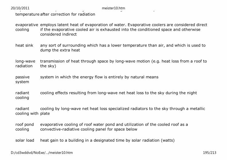
dry-bulb
temperature
the temperature of a gas or a mixture of gases indicated by an accurate thermometer
after correction for radiation
evaporative
cooling
employs latent heat of evaporation of water. Evaporative coolers are considered direct
if the evaporative cooled air is exhausted into the conditioned space and otherwise
considered indirect
heat sink any sort of surrounding which has a lower temperature than air, and which is used to
dump the extra heat
long-wave
radiation
transmission of heat through space by long-wave motion (e.g. heat loss from a roof to
the sky)
passive
system
system in which the energy flow is entirely by natural means
radiant
cooling
cooling effects resulting from long-wave net heat loss to the sky during the night
radiant
cooling with
cooling by long-wave net heat loss specialized radiators to the sky through a metallic
plate
roof pond
cooling
evaporative cooling of roof water pond and utilization of the cooled roof as a
convective-radiative cooling panel for space below
solar load heat gain to a building in a designated time by solar radiation (watts)
vapour pressure exerted by a gas, particularly one near to equilibrium with the liquid phase of
20/10/2011 meister10.htm
D:/cd3wddvd/NoExe/…/meister10.htm 195/213

vapour
pressure
pressure exerted by a gas, particularly one near to equilibrium with the liquid phase of
the substance
wet-bulb
temperature
temperature at which water by evaporating into air can bring the air to saturation
adiabatically (without heat extraction or addition) at the same temperature
Bibliography
ASHRAE (American Society of Heating, Refrigerating, Air Conditioning Engineers),
Handbook of Fundamentals 1981, N.Y., ASHRAE, 1981. Bahadori, M. N. Passive Space
Cooling in Hot Humid and Hot Arid Climates, paper presented to the UNCHS (Habitat) Ad
hoc Expert Group Meeting on the Use of Solar Energy and Natural Cooling in the Design of
Building in Developing Countries, 28 - 30 September 1983.
“Passive and Hybrid Convective Cooling Systems”, Proceedings of International Passive
and Hybrid Cooling Conference, American Section of International Solar Energy Society,
Miami Beach, November 1981.
Balcomb, J. D., State of the Art in Passive Solar Heating and Cooling, Los Alamos, 1976.
Ballinger, J. S. Harris, M. Key and U. Hora. Energy Efficient Site Planning Handbook, the
Housing Commission of New South Wales, Australia, 1982.
Celik, A. P., Passive Techniques in Solar Heating and Cooling, International Symposium on
Solar energy Fundamentals and Its Applications, Izmir, 1979.
Givoni, B., Options and Applications of Passive Cooling and Solar Passive Heating in Hot
Regions, paper presented to the UNCHS (Habitat) Ad hoc Expert Group Meeting,
September 1983.
20/10/2011 meister10.htm
D:/cd3wddvd/NoExe/…/meister10.htm 196/213

Man, Climate and Architecture, London: Applied Science Publishers, 1976.
Holmes, W. W., “A Comprehensive Categorization for Passive Cooling Techniques,”
Proceedings of the Fourth National Passive Solar Conference November 1981.
Page, J. K., Inter-relating Passive Cooling Aspects of Building Design with, their Passive
Solar Heating Potential, Department of Building Science, University of Sheffield, 1984.
Szokoloy, S. V., Experiences with an Active Solar Air Conditioning System, paper presented
to the SERIWA/NERDOC Solar Cooling Workshop, Perth, April 1980.
Yellot, I., “Passive Solar Heating and Cooling Systems”, ASHRAE Journal, January 1978.
6.2. Passive solar design
Buildings need to be heated, cooled and ventilated in almost all regions of the globe, if an
adequate indoor climate and comfort has to be provided to the occupants. Proper
architectural design, depending on climatic conditions, can help in providing them comfort
with no or extremely limited use of energy.
Depending upon the architectural design and geographical location of buildings, the
energy requirement for heating and cooling buildings can be considerable. It is in this
context that the concept of passive solar building design as a significant measure for
energy saving during the life time of any building has attracted great attention over the
past two decades, particularly after the global oil - crisis of 1974.
While the professional community with its research efforts is in search for new energy
sources, the sun is transmitting continuously, vast amount of energy. Although only one
trillionth of the energy reaches the Earth, this is still about 10,000 times the total
commercial energy used, so that even very modest progress in utilizing solar energy could
20/10/2011 meister10.htm
D:/cd3wddvd/NoExe/…/meister10.htm 197/213

provide a large part of mankind’s energy needs. For example, on a clean day, a surface
directly facing the sun receives about 1 KW of solar radiation per square metre (41).
Passive-solar design can be described as satisfying the thermal needs of building
occupants by using sun’s energy and other natural means. Buildings designed on the
principles of passive solar architecture are those which use the structure of the building
(walls, ceiling and floor) as a collector, storage and transfer mechanisms with a minimum
amount of mechanical equipment, while active design systems are generally those that are
very visible with collectors on roofs, pumps, plumbing, control systems and storage tanks.
6.3. Passive solar heating of buildings (42)
Relevance of passive-solar heating
Passive-solar space heating can be most effective in temperate climates, where there is
sufficient sun to make it work-well and where winter temperatures are cold enough to
make it cost-effective. It is useful to separate temperate zones into two different climatic
regions for purposes of this discussion: those with mild winter climates and those with
severe winter climates. The demarcation between the two is at the average monthly
midwinter temperature of about 8°C. In mild climates it seldom freezes in the winter, and
in severe climates it usually freezes every night for several months of the winter.
In regions of mild winter climate, buildings normally have low thermal resistance and are
uncomfortably cold throughout most of the winter. Supplementary heating, if used at all,
is makeshift and erratic; extra clothing is often the primary means of maintaining comfort.
In these climates, passive-solar heating alone, without added insulation, can markedly
improve the inside winter climate. By such techniques alone, the average temperature
inside, in mid-winter can be raised 5° to 10°C, and the need for supplementary heating can
be reduced by 60 to 90 per cent. This is not to say that conservation strategies are not
appropriate in regions with mild climates. Added insulation and reduced air leakage would
20/10/2011 meister10.htm
D:/cd3wddvd/NoExe/…/meister10.htm 198/213

not only make the building more comfortable but reduce the size of passive-solar
collection-area needed.
In regions with severe winter climate, passive-solar strategies taken alone are
inadequate; insulation must be added to achieve reasonable comfort levels. It is
recommended that insulation be preferably placed on the outside of the wall, protected by
a weather-proof outer sheathing, or in a cavity inside the wall. Extensive insulation should
be added to the roof, and all cracks should be sealed to reduce air infiltration. These
strategies will typically, reduce the heating requirements to about one-third or one-
quarter of the uninsulated value. Passive-solar strategies can then be implemented, as in
mild climates, to maintain comfort during most of the winter. Some supplemental heat will
still be required to maintain comfort during extended cloudy periods, but the net effect is a
building that will require only 10 to 20 per cent as much heat as buildings without
conservation or solar measures. Note, however, that the coldest temperature conditions in
many climates almost always occur during clear weather when passive solar heating
copes very well. Without back-up heating, the inside temperature would likely never drop
below 5° to 8°C, even under the most severe winter conditions. This inherent protection
against freezing is a considerable advantage.
Design considerations
Passive-solar technology is basically design-oriented. The orientation of buildings is such
that, it takes maximum advantage of environmental conditions to enhance thermal
comfort. The choice of passive-solar design-strategy should be based on a balance of
factors such as:
(a) socio-cultural characteristics of the users and use patterns of the building;
(b) construction techniques and materials available.
Severity of climate will determine the level of conservation, the design of details, and size
20/10/2011 meister10.htm
D:/cd3wddvd/NoExe/…/meister10.htm 199/213

of elements used for passive heating.
The tendency for buildings in the formal sector in urban areas to be of massive
construction in developing countries is an advantage for passive solar applications. The
mass provides heat storage to carry over daytime solar gains into the evening hours.
There is normally ample mass in buildings of adobe, brick, concrete block, stone, however,
a few adjustments in the use of such materials will result in the greatest heat-storage
effectiveness (such as using north/south partition walls between direct gain spaces).
Types of passive heating
The three passive-solar strategies of primary importance are direct gain, thermal storage
walls and sunspaces.
Direct gain is simply the use of windows on the equatorial side of the building. The direct
gain glazing area should be limited to no more than about 10 per cent of the floor area of
the building to prevent excessive temperature swings, degradation of materials within the
building by ultraviolet rays and glare. In mild climates, this may be a sufficient passive-
solar glazing area to meet heating requirements (see figure 1).
Thermal storage walls either Trombe walls, (figure 2) or water walls (figure 3) can be
used to balance heat delivery into the building. If the building is already of massive
construction, a Trombe wall can quite easily be built simply by painting or staining the
outside of the wall with a dark colour and glazing the wall outside. The incremental cost of
such a modification is relatively small. In severe winter climates, double glazing should be
used; in mild winter climates, one sheet of glazing is usually sufficient.
Another option, that of utilizing water in containers for thermal storage (a water wall), is
reasonable if suitable containers can be obtained at low cost. Containers should be painted
a dark colour on the side facing the window, but can be any colour on the room side.
20/10/2011 meister10.htm
D:/cd3wddvd/NoExe/…/meister10.htm 200/213

Sunspaces can either be attached to the building or incorporated in atria. A sunspace
consists of a direct gain room placed on the equatorial side of the building, separated from
the main living or working area of the building by a wall with openings that can be closed,
such as doorways or windows (figure 4). The sunspace has a large area of solar glazing
compared with the surface of the mass used for heat-storage and, thus, temperature
swings will typically be large (10° to 20°C). During the day, warm air is transferred from
the sunspace to the rest of the building, primarily by convection of warm air through the
connecting doors and windows which are left open during the day and closed at night The
temperature in the sunspace will drop somewhat below room temperature at night but
remain well-above outside temperatures. The use of an atrium within a building has
proven to be a very successful passive-solar design-strategy. If properly designed, an
atrium can provide passive-solar winter heating, daylighting and passive summer cooling
within a building and at the same time can serve as a useful living, working or public area.
Such atria have been included in the design of many commercial buildings and have also
been successfully used in several residential buildings.
Performance features
Used correctly, all three of these passive-solar design-options have comparable
performance and will save 160 to 320 kWh of auxiliary heating energy per year per sq. m.
of glazing surface. Any one of the three might be most suitable in a particular instance, or
a mixture of two or the three systems might be employed. A particular advantage of the
direct gain approach is its provision of daylighting in the building, reducing the need for
artificial lighting. The Trombe wall or water wall approach achieves both the most
effective carryover of heat from day to night and the best thermal comfort. The advantage
of the sunspace is its provision of an additional area within the building which can be used
as an air-lock entry, a traffic way or a greenhouse. Both flowering plants and vegetables
can be grown year-round in a properly constructed sunspace.
20/10/2011 meister10.htm
D:/cd3wddvd/NoExe/…/meister10.htm 201/213

Relating design strategies to climate
Local climatic conditions will affect both the design and the effectiveness of passive solar
heating strategies. Specific temperature climate zones can be commented on as follows:
Figure 1. Direct gain
Figure 2. Thermal storage wall (Trombe wall)
Figure 3. Thermal storage wall (water wall)
20/10/2011 meister10.htm
D:/cd3wddvd/NoExe/…/meister10.htm 202/213

Figure 4. Attached sun space
Upland continental climates tend to have sunny, cold winters, making passive solar
heating very attractive and cost-effective. If the climate is cold (less than 8° C, average
midwinter temperature), special care must be taken to prevent excessive heat loss from
the passive system, by means such as double glazing, use of selective surfaces (on a
thermal storage wall) or night insulation. The required passive solar glazing area might be
large (20 to 30 per cent of building floor area); thus a combination of direct and indirect
passive strategies is usually desirable. These regions also tend to have hot summer
conditions; in this case, special care must be taken to shade or cover completely the
passive glazing, so that overheating does not occur.
At moderate latitudes (25° to 50°) it is very important to orient the building so as to allow
maximum beneficial use of winter sun and maximum exclusion of summer sun. The most
effective configuration is a building long in the east-west direction and short in the north-
south direction. Windows and other passive solar glazing elements should be located on
the equatorial-facing side of the building. However, small windows might have to be
located on the opposite side and the east and west ends of view, emergency egress and
summer ventilation; they should certainly never be eliminated altogether. Suitable
overhangs used above equatorial-facing windows should exclude the direct summer sun
totally.
At low latitudes (0° to 75°) upland regions needing heating (such as the altiplano of South
20/10/2011 meister10.htm
D:/cd3wddvd/NoExe/…/meister10.htm 203/213

America) present the need for entirely different passive solar heating methods. A central
courtyard covered by horizontal glazing is effective, as is the use of east-or-west facing
passive solar glazing.
At very high latitudes (50° to 70°), there is usually insufficient solar energy to make a
solar system work in midwinter. A passive system can be cost-effective only if justified,
based on energy savings during the autumn and spring months. In new constructions,
added insulation might shorten the heating season to the point that passive solar is not
very cost-effective. However, in some retrofit situations, passive solar systems might be a
practical option.
Maritime temperature climates often have low-solar energy availability owing to fog and
cloud. However, the climate is usually mild, and the heating season very long so that
passive-solar heating can still be cost-effective. However, it is necessary to minimize heat
losses to ensure net positive gain. This might indicate that double glazing or selective
surfaces should be used. Sunspaces also tend to be especially successful in these
situations.
Short winter climates, often make it economically difficult to justify passive-solar heating-
strategies. With a heating season of only two or three months, even if it is sunny, it is
difficult to recoup the investment.
Climatic analysis for passive solar heating
The effectiveness and the design of passive-solar heating-systems depend both on the
winter heating needed and the solar energy available during the heating season. Figure 5
identifies four general zones according to these conditions:
20/10/2011 meister10.htm
D:/cd3wddvd/NoExe/…/meister10.htm 204/213

Figure 5. Suitability of passive heating according to solar availability and heating need
The heating needed increases as the outside temperature decreases, as the length of the
heating season increases, and as the inside temperature desired by the building occupants
increases. Solar availability in winter decreases as cloudiness increases and decreases as
latitude increases.
Zone 1: Passive heating effectiveness is greatest in Zone 1, as is the added investment in
double glazing, movable insulation or selective surfaces which can be justified to achieve
high performance.
Zone 2: Passive heating is very easy in this zone, as the size of system needed is generally
modest. Furthermore, locations having a Zone 2 winter climate frequently also have a hot
summer climate. Thus the passive-heating system must be carefully-designed to avoid
potential adverse effects in summer. This usually means that the passive-heating
apertures must be carefully-shaded in summer and, in extreme cases, should be
completely covered to prevent diffuse solar gains.
20/10/2011 meister10.htm
D:/cd3wddvd/NoExe/…/meister10.htm 205/213
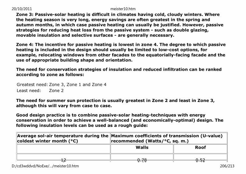
Zone 3: Passive-solar heating is difficult in climates having cold, cloudy winters. Where
the heating season is very long, energy savings are often greatest in the spring and
autumn months, in which case passive heating can usually be justified. However, passive
strategies for reducing heat loss from the passive system - such as double glazing,
movable insulation and selective surfaces - are generally necessary.
Zone 4: The incentive for passive heating is lowest in zone 4. The degree to which passive
heating is included in the design should usually be limited to low-cost options, for
example, relocating windows from other facades to the equatorially-facing facade and the
use of appropriate building shape and orientation.
The need for conservation strategies of insulation and reduced infiltration can be ranked
according to zone as follows:
Greatest need: Zone 3, Zone 1 and Zone 4
Least need: Zone 2
The need for summer sun protection is usually greatest in Zone 2 and least in Zone 3,
although this will vary from case to case.
Good design practice is to combine passive-solar heating-techniques with energy
conservation in order to achieve a well-balanced (and economically-optimal) design. The
following insulation levels can be used as a rough guide:
Average sol-air temperature during the
coldest winter month (°C)
Maximum coefficients of transmission (U-value)
recommended (Watts/°C, sq. m.)
Walls Roof
12 0.78 0.528 0.60 0.40
20/10/2011 meister10.htm
D:/cd3wddvd/NoExe/…/meister10.htm 206/213

8 0.60 0.40
0 0.45 0.30
8 0.37 0.25
Infiltration should also be carefully controlled, consistent with maintaining adequate
indoor air quality.
In applying passive-solar heating-techniques, two points should be kept in mind. The first
is to avoid embellishing the system with unneeded (and usually counter productive)
gadgetry. The second is to make multiple use of elements where possible. For example, a
trombe wall can support the roof and serve as an acoustic barrier between a room and a
noisy street. A sun space can in addition serve as an airlock entry or a passageway. This,
passive-heating techniques are architecturally versatile, simple, reliable and economical.
The overcost of passive-solar heating-techniques is usually very nominal, normally not
more than 5 per cent of the cost of the building, and should never exceed 10 per cent.
Costs can be kept low following the advice given above, in which case the overcost can be
shared among the multiple functions that the passive element serves.
Design methods
Methods for the passive-solar design of buildings are based on bioclimatic analysis, which
is a systematic procedure for the assessment of thermal comfort in relation to external
climate. Its purpose is to identify desirable adaptations of structure to meet human
comfort needs under specific climatological conditions. Both bioclimatic analysis and
passive-solar heating-design require certain climatological data such as out-door air
temperature, humidity, wind strength, direction and frequencies of solar radiation,
sunshine and cloud distribution and precipitation. There are simple but validated methods
of thermal analysis used by practising architects and engineers. Therefore, it is not usually
20/10/2011 meister10.htm
D:/cd3wddvd/NoExe/…/meister10.htm 207/213

necessary to use cumbersome modelling and simulation techniques requiring large
computers. It is, however, necessary to evaluate the materials available in a specific
locality, the construction techniques of in-use and any socio-cultural constraints. A
preliminary design can be prepared using information in the form of general guidelines,
but detailed local climatic data will then be required to permit specific application. There
are three levels of analysis, namely:
Level
1
Guidelines useful at the beginning of the design.
Level
2
Simple analysis procedures which can be used to check performance as schematic design
proceeds.
Level
3
Complex analysis procedures to check performance towards the end of the design process.
It is extremely desirable that these procedures be amenable to rapid checking of
calculations by hand.
For levels 2 and 3 in the above list, the analysis should provide four key pieces of
information: the average inside temperature for the building each month, the clear-day
temperature swing inside the building in midwinter, the annual auxiliary heat needed to
maintain a given minimum temperature throughout the winter, and the average and peak
daily inside temperatures in hot weather.
Average inside temperatures and temperature swings pertain to the comfort which would
be obtained in an unheated building. This is relevant to situations where space heating is
not used in any case, and the purpose of passive-solar heating is to improve the inside
20/10/2011 meister10.htm
D:/cd3wddvd/NoExe/…/meister10.htm 208/213

environment. Annual auxiliary heat needed identifies the energy savings potential of the
passive system in situations where a backup heating system is employed. Average and
peak daily inside temperatures enable the year-round performance to be checked, so that
excessive overheating does not occur in summer.
State of the art-passive solar-water heating
The most cost-effective solar-water heating-systems are currently found in those areas of
the world where conditions are suitable for combining flat-plate collectors with a passive
movement of the water into the storage tank. They have the advantage of supplying hot
water without the need for any connection to an electricity supply. Such systems are
easiest to devise in climates without risks of freezing. Most of these systems are passive
thermosyphon water heaters. Encouragement should be given to the development of this
industry at the local level, and the problems of effective integration with local-building
techniques should be evaluated.
Conclusions
Passive-solar heating will not only save energy and help reduce the adverse
environmental impacts of fossil-fuel use but also vastly improve the comfort and livability
of buildings. To promote the use of passive-solar design of buildings, priority should be
given to the dissemination of information on the methods and materials for passive
design, e.g. through the preparation of national and regional design handbooks setting out
design methodologies. Sets of minimal meteorological data, as well as information on
thermal properties of indigenous building materials, are needed to make the use of
passive-solar technologies possible. A systematic programme for the construction of
demonstration buildings is an important step to prove that solar-heated buildings are
successful in conserving fuels while providing comfort. Training and education in passive
solar design would increase the interest of professionals and users alike in passive solar
20/10/2011 meister10.htm
D:/cd3wddvd/NoExe/…/meister10.htm 209/213

design technologies.
Glossary
Airlock entry a vestibule enclosed with two air-tight doors for permitting entrance without
significant air or heat exchange
Atrium a central-courtyard type of space within a building, either open to the sky or roofed
over the whole or in part with glass or other transparent material
Clerestory a vertical window placed high in a wall near the eaves and used for light, heat-gain
and ventilation
Direct gain energy collection through windows or other glazing into occupied space, with heat
storage within the confining surfaces and other materials of the building
Glazing materials which are translucent or transparent to short-wave solar radiation,
including glass and plexiglass
Infiltration uncontrolled air flow into or through a building via such openings as gaps under
doors, chimneys without dampers and badly-fitting windows
Insulation materials which conduct heat slowly, such as particle board, perlite, cellulose fibres,
mineral wool and fibreglass
Night
insulation
insulation used only at night, in the form of shutters, curtains, etc.
20/10/2011 meister10.htm
D:/cd3wddvd/NoExe/…/meister10.htm 210/213

Passive system system in which the energy flow is entirely by natural means
Retrofit (v) add a solar heating or cooling system to an existing building previously-
conventionally heated and/or cooled
Selective
surface
one which has a high absorptivity and a low emissivity; such surfaces are commonly
used on flat-plate solar collectors and on storage walls
Sol-air
temperature
an imaginary temperature of the layer of air adjacent to the surface being
considered and the equivalent of the combined effect of solar radiation and air
temperature
Supplementary
heating
auxiliary or back-up heating-system; a constantly available source of heat energy
which is brought into operation when the solar system storage has been exhausted
and the need for heat exists
Temperature
swing
fluctuations in temperature
Thermosyphon heat and mass transport by natural convection of a fluid; in air thermosyphon the
fluid is air, in water thermosyphon it is water, e.g. in a thermosyphon water heater
Thermal
Storage wall
a wall in which heat storage material is located closely behind solar collection
glazing, e.g. a Trombe wall
20/10/2011 meister10.htm
D:/cd3wddvd/NoExe/…/meister10.htm 211/213

Trombe wall thermal storage wall of masonry (concrete, brick, adobe, rock, etc.)
U-value heat transfer coefficient; the capability of a substance to transfer the flow of heat
(used to describe the conductivity of a material or composite of materials used in
construction)
Bibliography
ASHRAE (American Society of Heating, Refrigerating, Air Conditioning Engineers).
Handbook of Fundamentals 1981. N. Y.: ASHRAE, 1981.
Balcomb, J. D. and others. Passive Solar Design Handbook, Passive Solar Design Analysis.
Los Alamos Scientific Laboratory, Los Alamos, New Mexico: The United States, Department
of Commerce, National Technical Information Service, 1980.
Balcomb, J. D., State of the Art in Passive Solar Heating and Cooling. Los Alamos, 1976.
Ballinger, and others, Energy Efficient Site Planning Handbook. The Housing Commission
of New South Wales, Australia, 1982.
Celik, A. P., “Passive Solar Design for Developing Countries”, Building Research and
Practice, March/April 1984.
The First Passive Solar Home Awards. Franklin Research Centre, Philadelphia,
Pennsylvania. January 1979.
Givoni, B., Design Guide for Direct Gain Solar Heating. Ben Gurion University of Negev,
1983.
20/10/2011 meister10.htm
D:/cd3wddvd/NoExe/…/meister10.htm 212/213
Mazria, E., The Passive Solar Energy Book. Emmaus, Pennsylvania: Rodale Press, 1979.
Page, J.K., Inter-relating Passive Cooling Aspects of Building Design with their Passive
Solar Heating Potential. Department of Building Science, University of Sheffield, 1984.
Passive Solar Buildings Los Alamos Scientific Laboratory/Sandia Laboratory, July 1979.
Solar Dwelling Design Concepts. Washington, D.C.: The United States, Department of
Housing and Urban Development, May 1976.
A Survey of Passive Solar Buildings. The United States, Department of Housing and Urban
Development/U.S. Department of Energy HUD-PDR-287 (2) February 1979.
UNCHS (Habitat), Energy Conservation in the Construction and Maintenance of Buildings -
Volume 1: Use of Solar Energy and Natural Cooling in the Design of Buildings in
Developing Countries, HS/49/84E Nairobi, 1984.
UNCHS (Habitat), Natural Design Handbook Prototype on Passive Solar Heating and
Natural Cooling of Buildings, HS/182/89E, Nairobi, 1989.
UNCHS (Habitat), Bibliography on Passive Solar Systems in Buildings, HS/173/89E,
Nairobi, 1989.
20/10/2011 meister10.htm
D:/cd3wddvd/NoExe/…/meister10.htm 213/213