glass - outline of a development - philips bound... · 316 philips tech. rev. 42,no.10/ll/12,...
TRANSCRIPT

316 Philips Tech. Rev. 42, No.10/ll/12, 316-324, Sept. 1986
Glass - outline of a development
In the industrial development of our company, asoutlined in this Anniversary issue for a number offields during the last half century, glass has oftenplayed an important role. In the creation of new pro-ducts it has been necessary time and again to have newcompositions of glass. There has been a constantlyrecurring need for new manufacturing methods toallow the continued economic production of theseproducts. Consequently the industrial development ofour company has also been reflected in changingforms of organization in the Glass Division - nowknown as the Main Supply Group, Glass.The outline givenbelow of the various changes that
have taken place is divided into three periods, whichwill be dealt with in three separate sections:• The period from 1916 to 1950, in which the mainemphasis of Philips products was on 'light and sound'.• The period from 1950 to 1975, in which the mainemphasis moved towards picture tubes and industrialapplications.• The period from 1975 up to today, in which themain emphasis hasmoved to products for informationsystems and office automation. In the section dealingwith this period weshall also attempt to assess the rolethat glass is likely to play in the future.
The years 1916-1950; products for 'light and sound'
Our young company was in peril of an early demisein the war years 1914-1918when the supply of incan-descent lamp bulbs from Austria-Hungary and Ger-many showed serious signs of drying up. Anton andGerard Philips therefore decided that the companyshould have its own glassworks, and this was dulyopened in January 1916. In the first ten years thisestablishment grew into a large-scale labour-intensivebusiness in which the lamp bulbs were 'mouth-blown'and the glass tube for stems (flares) and exhaust tubingwas drawn by hand. In 1926 the glassworks produceda hundred million electric lamp bulbs with a workforce of 2000, which included 600 glassblowers and300 tapping-off operators.The diversification into glass products soon became
significant. In about 1920 Philips started manufactur-
Dr Ir A. Kats was with the Main Supply Group, Glass, PhilipsNPB, Eindhoven, before his retirement.
A. Kats
ing what were then called wireless valves, for radioreceivers (or 'wireless sets'). They were indeed shapedjust like lamps. Later this activity extended to includethe manufacture of the receivers, which included thevalves that had meanwhile been developed as compo-nents. The manufacture of valves - still primarilybased on the familiar trinity of 'glass, vacuum andfilaments' - wa.s still quite compatible with lamp-manufacturing technology.
In the early twenties a demand arose for X-raytubes, for which new types of glass were developed.But diversification was continuing in the lamp sectoras well, since a need had arisen for glass for high-power incandescent lamps. The type of glass requiredhad to have a high softening temperature and be ableto withstand severe temperature shocks. A borosilicateglass was used for this application. Since this glass hasa low thermal expansion coefficient, tungsten wire hadto be used for the lamp lead-throughs. The same typeof glass was later used for the envelopes of X-raytubes.
The company also became involved in the develop-ment of radio transmitting equipment, initially to meetthe demand from radio amateurs for transmittingvalves and rectifiers and finally for building complete-transmitter installations. Since low dielectric lossesare important for transmitting valves, special glasseswere developed, suitable for tungsten or molybdenumlead-through wires.
This diversification of glass products and types ofglass called for new raw materials, melting methodsand shaping techniques: glass technology moved intothe production line. In the twenties, thirties and fortiesmouth-blowing and manual drawing of glass reacheda level of craftsmanship high enough for the com-pany to produce large numbers of prototype envelopesand tubes. In the late thirties the first picture-tubeenvelopes were mouth-blown for Philips ResearchLaboratories, to be followed later by the manualdrawing of the first fluorescent lamps.After 1920 the rapidly increasing demand for glass
left the glassworks no option but to mechanize theblowing and drawing operations. To do this it wasnecessary to change from batch melting in pots tocontinuous melting in furnaces. This was a gradualprocess that went through a number of phases and fin-

Philips Tech. Rev. 42, No. 10;11;12 GLASS 317
ally resulted in the present type of tank furnace, con-sisting of a melting end connected to a working endfrom which the glass flows through one or morefeeders to the glass-forming machines.In the United States glass tubing was already being
mechanically drawn in about 1920 by the Dannerprocess, in which a stream of hot glass flows on toa rotating ceramic mandrel (figs 1 and 2). But thelicence fees for this process were so expensive thatPhilips decided to develop their own process: in thePhilips horizontal drawing machine a continuousstream of glass flows into a hollow rotating ceramiccylinder.Until 1950 the Philips horizontal drawing machine
was used for making stems and exhaust tubes for in-candescent lamps and glass tubing for thermionicvalves. The situation changed, however, when thefluorescent lamp appeared. This required long thinenvelopes with very tight tolerances for the diameterand the wall thickness. These requirements are moreeasily met with the Danner process, because the ther-mal conditions can be carefully controlled while thehot glass is being drawn from the ceramic mandrelthrough the mandreloven; this is virtually impossiblein the Philips process. Meanwhile the patents on theDanner process had expired, so it was decided to Fig. 2. Front view of the ceramic mandrel with the 'onion' and glass
flowing from it.
10
introduce this process in our glassworks as well, firstfor the manufacture of fluorescent-lamp envelopesand later for making stems and exhaust tubing.
The mechanization of bulb blowing also took placein a number of phases. In 1930 the 4-head bulb-blow-ing machine was put into operation, on which eachbulb is moulded at four stations at a rate of 375 bulbsper hour. The bulb quality obtained was very good,but the machine was not very suitable for higher ratesand also required a great deal of maintenance. In thesecond phase an 8-head rotating bulb-blowing machineor carousel was therefore developed [11, which couldturn out 1500 bulbs per hour. In the third phase fur-ther optimization of this machine led to the 16-headmachine, whose hourly output was raised to 4500 stan-dard 60-mm bulbs (fig. 3).With the further growth of the European market for
incandescent lamp bulbs even this machine proved tobe too slow, and in 1968 the ribbon process was intro-duced (fig. 4). This process has since been optimizedyet again and is capable of producing 80000 bulbs perhour. Such a high production capacity per machinemeans that a single factory is sufficient for meeting theentire West European demand for electric lamp bulbs.
[IJ See P. van Zonneveld, Philips Tech. Rev. 22, 320·336, 1960/61.
Fig. 1. Schematic arrangement of the Danner process. The moltenglass flows from the feeder 1 through the orifice 2 to the mandrel3.The rate of flow of the glass is controlled by a regulating pin 4.Rotation of the pin has a homogenizing effect on the glass. Theceramic mandrel is driven by a hollow metal shaft 5. Behind thenose 6 glass flowing from the mandrel forms an 'onion' 7. Airis blown into the hollow metal shaft (8). The rate of flow of theglass, the temperature of the 'onion', the pressure of the air in themandrel and the speed of the drawing machine 9 determine thedimensions of the tubing. High dimensional accuracy is achieved ifthe glass flowing on the mandrel does not vary greatly in tem-perature. The temperature in the mandreloven la is controlled bythe gas burners projecting through the wall of the oven, and theshutter 11.

318
In the factories outside Europe the carousel haslong been standard. In countries with a growing lampindustry, however, a need soon arose for a machinethat had a greater capacity than the standard carousel,though not nearly as high as that of the ribbon mach-ine. In the early seventies the Glass Division thereforedeveloped the 'Karibo' machine, which is a cross be-tween the carousel and the ribbon machine, and has acapacity of 7000 bulbs per hour. This machine hasmeanwhile been installed in countries such as Japan,Mexico, Brazil, Argentina and Spain.
In this article it is not possible to deal at length withall the new products of the company in which manualand mechanical glass-production methods played animportant part in this period. One exception will bemade, however, for the low-pressure sodium lamp.
o
b cA B o E F
Fig. 3. a) View of part of the 16-head carousel bulb-blowing mach-ine. Note in particular the following parts: two matching halves ofthe blow-mould la and lb, the 'gobcatcher' 2, the hole 3 in the ori-fice plate, the lever 4 and the moulding and puffing head 5. b) Dia-gram showing stages (A-G) in the manufacture of the glass bulb.A) Shears sever a 'gob' from a glass rod. B) The gob is collected inthe gobcatcher 2, consisting of a plunger cup and a slide that canmove in a radial groove in the orifice plate, which rotates continu-ously under the puffing heads. The tray containing the gob is thenslid inwards by the lever 4. C) The plunger presses the glass intojaws mounted around the edge of the plunger. D) The mouldingand puffing head returns to its initial position, with the glass 'bis-cuit' in the jaws, and the empty gobcatcher moves radially outwardsagain. E) The moulding and puffing head descends until it abutsagainst the tapered edge of a ring on the orifice plate. The puffinghead now rotates with the orifice plate and the glass begins to sag,forming a 'parison' . This process is accelerated by blowing a fewpuffs of air into the parison from the puffing head. The two halvesof the mould la and lb close around the parison (F). 0) After themould has opened again, the moulded bulb is ejected from the jaws.
A. KATS Philips Tech. Rev. 42, No.10/11/12
4 5
\\
"f6/
7
Fig. 4. Diagram of the ribbon machine. A continuous stream ofglass from the furnace passes between two water-cooled rollers 1,which produce a ribbon from it. The right-hand roller has circular'cut-outs', so that the ribbon contains regularly spaced protrusions.When the protrusions are exactly above the holes 2 in the metal con-veyor belt 3, the blowheads 4 have also arrived at exactly the rightposition. The blowheads are mounted on an endless belt 5. Theglass now begins to sag between the still open halves of the mouldtongs 6, which travel with the ribbon on an endless belt 7. A fewpuffs of air are blown into the sagging parison, the mould tongsclose and the bulb is blown. After the two halves of the mould haveopened again, the bulbs are allowed to cool a little and are finally'tapped off' from the ribbon.
G
The main contribution from the Glass Division tothis product was the provision of an inner bulb that isnot discoloured by sodium during the discharge anddoes not absorb argon. For a long time it was difficultto meet these two requirements. Borate glass, which isresistant to sodium and does not absorb argon, hastoo small a transitional range near the softening pointfor the lamp to be formed easily in the traditionalmanner. The problem was finally solved by means ofa soda-lime glass that was coated inside with a layer ofborate glass about 80 urn thick. In the drawing pro-cess developed for this application the free-flowingmolten borate glass is transferred in accurately de-fined quantities from a small platinum glass furnaceinto the orifice of the furnace from which the soda-lime glass is drawn. With carefully designed glass com-positions the borate glass spreads uniformly over thesoda-lime glass.
As a result of the developments outlined above forglass technology and production machines a GlassDevelopment Centre was set up in 1957. This is alaboratory that also has its own pilot productionplant. Since its inception the laboratory has been acontinuous source of innovation in products and pro-cesses.
The years 1950-1975; picture tubes and industrialapplications
Monochrome television
Monochrome picture tubes for television were firstproduced in quantity at Philips in about 1950. In theUnited States television-tube production had alreadymade great headway, led by RCA. The first tubes had
Philips Tech. Rev. 42, No. 10/11/1.2
a glass screen sealed to a metal cone. In 1949Americantube manufacturers changed to a glass cone, becauseit was cheaper and because it enabled glass manufac-turers to respond more rapidly to developments ofnew types. Philips followed the same line.It soon became clear that the television market had
an enormous growth potential. Our company there-fore wanted to have a free hand in type development,supplies and prices of the principal components, espe-cially the glass components. Efforts were made at firstto set up joint production with the major glass sup-pliers in the United States. An argument in favour ofthat approach was that one of these firms held thebasic patent for sealing the screen to the cone. Thearrangement was not successful, however, and Philipstherefore decided in 1950 to build its own pressed-glass plant, which began operations in 1954.In these years Philips was confronted with a situa-
tion resembling that in the years of World War I, whendifficulties with the supplies of electric lamp bulbs putthe expansion of the company in Jeopardy. Because ofthe strong demand for glass components for televi-sion, it looked as if a monopoly in supplies was immi-nent. Philips therefore acted swiftly to expand its tele-vision-glass plants, and by 1960 five television-glassfurnaces were already in operation.It is worth mentioning here the development of the
cone presses. In the early period the cones, which werestill of the 70° type, were made of pressed glass. Atabout that time, however, Coming Glass invented thespinning process for making cones (a centrifugal pro-cess) and went over to this process, with their licen-cees. Since Philips was unable to obtain a licence forthis technique, it was obliged to continue with thepressing process. In later years the cones became lessdeep, a trend that was stimulated by other develop-ments in picture tubes at Philips. The angle first wentto 90°, then 110°. Since it is easier to press a flatterworkpiece accurately than to spin it, spinning becameless of an advantage and Philips found themselves ina favourable position again. Through the years theGlass Division has steadily perfected the cone-press-ing process and has maintained its leading positionfor many years.
Colour television
In the period 1960-65 preparations were made tomanufacture glass components for colour television.Itwas clear that this would require very considerablechanges in production, since it would be necessary totake into account:• other types of glass for both screen and cone;• tighter tolerances for the surface and the edge of thescreen;
GLASS 319
• the necessity to seal pins into the glass, by r .f, heat-ing, for attaching the metal shadow mask.The first point referred to the need for a glass with ahigher softening temperature than that of the glassused for monochrome television, which would alsohave to be of appreciably better optical-quality. Theother two points meant that a high-precision machinewould have to be developed for inserting the pins andperforming measurements.The international recognition that Philips had
gained in the meantime for its technical results in theproduètion of glass for monochrome televisionsmoothed the way to a 'know-how' contract withOwens-Illinois, a leading American glass manufac-turer. Starting up the manufacture of glass com-ponents for colour television was consequently a lesshectic affair than it had been for monochrome tele-vision.Philips also had a considerable influence on the
composition of television glass. Other glass manufac-turers had long used raw materials containing fluorineto speed up the melting of the glass. There are threereasons why Philips did riot do this:• there was a risk of cathode poisoning by fluorinereleased in the tube; this could shorten the life of thetube;• the emission of fluorine. compounds from glass fur-naces could eventually pollute the environment;• fluorine also reduces the life of the pressing tools.The Glass Division therefore developed types of fluor-ine-free glass that gave very similar melting behaviourto fluorine glass.Another problem was the discoloration of the screen
glass by electron bombardment, especially at the hightube voltages (30-40 kV) used for colour television.Philips discovered that this effect could be suppressedby adding Ce02 to the screen glass. Both develop-ments were adopted by nearly all the manufacturersthroughout the world.All this meant that by about 1972 'Philips Glass'
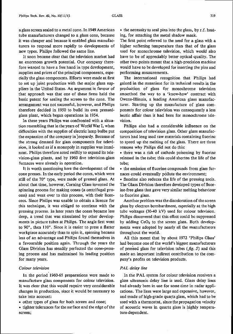
had become one of the world's biggest manufacturersof pressed glass for television tubes (fig. 5) and thismade an important indirect contribution to the corn-pany' s profits on television products.
PAL delay line
In the PAL system for colour television receivers aglass ultrasonic delay line is used. Glass delay lineshad already been in use for some time in radar appli-cations. The lines were large and expensive, however,and made of high-grade quartz glass, which had to beused with a thermostat, since the propagation velocityof acoustic waves in quartz glass is highly tempera-ture-dependent.

320
Fig. 5. Screens for colour picture tubes being pressed in the tele-vision pressed-glass works at Aachen, West Germany.
Philips developed a small inexpensive glass delayline for the PAL system; it had the following charac-teristics [2]:
• the propagation velocity of the shear waves used islow (so the dimensions can be small);• the temperature coefficient of the propagationvelocity is virtually zero (so a thermostat is unneces-sary);• the glass is highly stable, so that the delay does notvary with time;• the attenuation is low.Glass delay lines of this type are still used interna-
tionally in PAL!SECAM colour television receivers,and they were also used even more extensively later invideo recorders.
Prismatic colour-separation systems
The Philips colour television camera has becomewidely known through its use of the 'Plumbicon' tube,which has outstanding colour sensitivity, especially tored. To exploit this feature to the full, the optics de-partment of the Glass Division supplied an exit win-dow of borosilicate glass of very good surface quality,in combination with an anti-halo window, i.e. a win-dow that has a dark layer at the edges to absorb scat-tered light and an evaporated anti-reflection coating
A. KATS Philips Tech. Rev. 42, No. 10/11/12
on the 'scene' side. For the camera itself a prismaticcolour-separation system was developed which wasoptimized to match the colour-sensitivity of the'Plumbicon' tube. This system reflects the green andred components of the signal from two faces of theprism, while the complementary component of thelight (the blue signal) passes straight through. Thereflection mirrors for the green and red signals eachconsist of a set of vacuum-evaporated thin films, andthe entire system meets extremely tight tolerances forthe permitted wavelength range, even after long use.
The quality reputation that Philips won in theseyears for colour television was partly due to this newproduct.
Reed relay
Another professional product that was highly im-portant for Philips from 1965 to 1980 was the reedrelay. These relays have contacts mounted on 'reeds'sealed into a length of narrow glass tubing and areactuated by a low electric current. Before the digitiza-tion of telephone exchanges these relays were widelyused to replace the slow mechanical relays. The largeorders from Saudi Arabia were very largely due to thequality of the reed relays.The Glass Division's contribution to this product
was the manufacture of the glass tube in which thereed switches were sealed with metal lead-throughs.The relays were required to switch on and off reliablymillions of times. This means that during the sealingprocess there must be no oxidation or contaminationof the metal strips by vapour products of the glass. Tomeet this requirement a low-softening-point glass wasdeveloped that produces a minimum of vapour pro-ducts. This glass is green, since ferrous iron is dis-solved in it during melting, and this makes it possibleto melt the glass tubes at the lead-throughs by infra-red radiation from a halogen lamp. It is therefore un-necessary to use a gas flame, which could contaminatethe metal strips.
Quartz glass
Quartz-glass tubing has always been an importantenvelope material for high-power lamps, such as high-pressure mercury-discharge lamps, metal-halide andhalogen lamps. Its advantageous properties are a highsoftening temperature, above 1200 oe, and high resis-tance to chemical attack and temperature shock.
Through the years the requirements placed onquartz glass in regard to the gases dissolved in it aswell as bubbles and other inclusions ~ave become in-creasingly stringent. The dimensional specificationshave also become stricter. In specifying purity it wascustomary in the sixties to think in terms of parts per

Philips Tech. Rev. 42, No. 10/11/12
million, but today we have moved into the parts-per-billion range, e.g. for Cu and Fe and for hydroxylgroups. To meet these requirements the Glass Divisionintroduced a number of innovations:• to replace the rock crystal formerly used as the rawmaterial, which was too expensive and not constant inpurity, a process was developed for the purification ofcertain kinds of quartz sand;• a new type of electrically heated furnace was devel-oped, in which the materialof the furnace is almostunaffected by continuous operation at temperatureshigher than 2000 °C, so that there is very little conta-mination of the glass.Also introduced were:• a melting process in which the bubble content of theglass produced is reduced to virtually zero, and• a drawing process controlled by photosensitive sen-sors, giving the glass tubing exceptionally high dimen-sional accuracy.These innovations were followed by methods for
controlled doping of the glass. An important exampleof this is the '321' glass, specially manufactured forhalogen lamps for vehicles. The addition to this glassof controlled amounts (a few hundreds of parts permillion) of BaO, AbOs and K20 results in a largereduction in softening temperature: 950 oe against.1250 oe for pure quartz glass. This has considerableadvantages for automobile lamp manufacture. Asoftening temperature as low as this is acceptable forautomobile lamps, since the wall temperature of alamp does not exceed 700 oe, and on the other handthe low softening temperature means that the pro-cessing rate on the lamp machines can be substantiallyhigher. Also, the quality of the pinch of the molyb-denum-tape lead-through of the lamp benefits fromthe improved softening behaviour of the glass.
Fibre-optic plate
This review of the period 1950-1975 will concludewith a brief mention of the fibre-optic plate, whichwas developed in about 1965 for application in X-rayimage intensifiers and in the camera tubes associatedwith them [Slo
The vacuum-tight plate is composed of millions'of square fibres with a pitch of about 10 urn. Thefibres consist of a core with a high refractive index(nD :::::1.80) and a cladding with a low refractive index(nD :::::1.50). Each fibre acts as a 'light pipe' whichconducts an image through the plate via the core with-out distortion. Light conduction via the cladding and
[2] See F. Th. Backers, Philips Tech. Rev. 29, 243-251, 1968;A. J. Zijlstra and C. M. van der Burgt, Ultrasonics 5, 29-38,1967.
[3] See B. van der Eijk and W. Kühl, Philips Tech. Rev. 41,137-148, 1983/84.
GLASS 321
fibre deformation caused by manufacturing errors cangive rise to light scattering. At regular distances in theplate there are therefore opaque fibres, called EMAfibres (Extra Mural Absorption), which eliminate thescattered light.The manufacture of fibre-optic plates takes place in
a number of discrete stages. Each intermediate prod-uct is carefully inspected for quality, so that the finalresult is a high-grade end-product.Through the manufacture of this product, whose
quality is unrivalled throughout the world, our com-pany was also able to gain the know-how required forthe production of glass fibres for optical communica-tions, which will be dealt with in the next section.
The years 1975-2000; information systems and officeautomation; the near future
In the seventies, Japanese competitors strengthenedtheir position considerably by building very largemanufacturing units in which production was basedon a quality principle carried to very great lengths. Inthis way they were able to achieve high yields andhence low prices. To restore its competitive power, thePhilips group adopted the same principles. Pressed-glass activities, for example, were concentrated at afew locations in Europe, South America and the FarEast, and the quality principle was also introduced inthe Glass Division. In this context, 'quality' is devel-opment and production with the minimum of errorsand defects.The making and processing of glass, because of its
historical evolution, has always been an integral andstrongly interactive process. This implies that all theprocessing stages, such as batch preparation, melting,pressing, grinding and polishing have to progresssmoothly one from the other, so that all the stagesinteract. This conflets with the quality principle, inwhich each stage - after quality control - shouldlead to a fault-free intermediate product, with a per-fect end-product at the end of the chain. In attemptsto approximate as closely as possible to this principle,the glass-development departments made a thoroughstudy of all the processing stages and fixed all theparameters that determine each process. In this waythey gradually introduced a situation in which the finalmanufacture is divided into discrete stages, whichmust each be accurately controllable. This approachsoon gave a higher production yield and products ofimproved quality.Two recent developments in which this approach
has proved successful will now be discussed: the manu-facture of quartz-glass fibres for telecommunicationand the manufacture of aspheric lenses.

322
Optical jibres for telecommunication
There are three main requirements that an' opticalfibre has to satisfy [41:
• thefibremust behave as a waveguide, with no lateralescape of light pulses;• the attenuation due to absorption and scatter mustbe as low as possible;• the dispersion must be as small as possible.The first requirement is met by constructing a quartz-glass fibre from a core with a high refractive index anda cladding of low refractive index, in the same way asfor fibres in a fibre-optic plate. The second require-ment is met by using high-purity raw materials for thequartz-glass and by ensuring that no contaminants,such as Fe, Cu and hydroxyl groups, are introducedduring manufacture.
As regards the third requirement, low dispersion, adistinction has to be made between colour dispersionand mode dispersion. Colour dispersion is importantbecause the light from the source will have a finitespectral width. In the case of light from a GaAs laser(a multifrequency laser), which has a spectral width ofabout 2 nm, transit-time differences of 0.1 ns canoccur between the spectral components over a dis-tance of 1 km. It would be better to work with a laserthat emits at exactly one wavelength (a single-fre-
Fig. 6. Diagram of a PCVD arrangement used in the manufactureof optical fibres. A silica tube (1) enclosed by a furnace (2) carries agaseous mixture (3), consisting of GeCl4, SiCl4, C2F6 and 02. Thequantities of these constituents are controlled by a process com-puter. A non-isothermal microwave plasma is generated in a cavityresonator (4), which moves rapidly backwards and forwards alongthe tube. 5 pumping section. The plasma activates the followingreactions: SiCl4 + 02 --+- Si02 + 2Cl2 and
GeCl4 + 02 -+ Ge02 + 2C12.A complex reaction also takes place between C2F6 and 02, with theproduction of fluorine, which opposes the formation of OH groupsand thus prevents the occurrence of unwanted optical absorption inthe glass at 1370, 950 and 725 nm.
A. KATS Philips Tech. Rev. 42, No. 10/11/12
quency laser), e.g. at 1300 nm or 1550 nm, where theattenuation in the quartz-glass fibre is at a minimum(0.4 dB/km at 1300 nm, 0.2 dB/km at 1550 nm). Inpractice, however, a single-frequency laser is virtuallyimpossible to make.Mode dispersion can be avoided by making thefibre
core so small that only one mode is transmitted. An-other method of eliminating mode dispersion is to usea fibre with an almost parabolic variation of the re-fractive index across the core (graded-index fibre).This eliminates transit-time differences between thedifferent modes.For the manufacture of graded-index fibres Philips
have developed a method that is applied in threephases. The first phase is based on the PCVD process(Plasma-activated Chemical Vapour Deposition) [51,
jig. 6. In this process the quartz glass is separated outin layers from a gaseous mixture of SiCI4, GeCI4,C2F6 and 02 by means of a reciprocating plasma. Thereactions are very efficient. Since there is a directtransfer of energy into the gas mixture, there is nothermal inertia and the very thin layers can be formedvery rapidly. The theoretically required refractive-index profile can be accurately approximated by usinga process computer to program the gas composition
60%
40
20
00 _[a2 a4 os os 1.0 1.2 1.4dB/km
Fig.7. Distribution of the attenuation coefficient at 1300 nm of abatch of I600-km multimode fibres [61,made by the PCVD method.
20%
r-
r- r-
r-
r-
r- r-
LJ\r [bv,
15
10
5
00 0.6 1.42.2 3.0 3.8 4.6 5.4 GHz x km
Fig.8. Bandwidth distribution of the same fibres as in fig. 7 [61.Thebandwidth refers to a I-km fibre.

· Table I. Data relating to pilot projects with optical-fibre cable.
Project Year Distance Regener- Number System Wave- Cable Fibrein km ation of capacity length attenu- attenu-
distance fibres Mbit/s of laser ation ationkm nm dB/km dB/km
Berlin I 1978 4.3 4.3 6 34 850 6 5.5
Geldrop, 1979 16 8 6 140 850 4.5 4.0in-houseNürnberg/ 1981 12.3 6 2 34 850 4.5 4SchwabachHelmond/ 1982 10.1 9 6 140 850 4.5 4EindhovenBerlin III 1982 9 9 4 140 1300 1.5 1.3
Hamburg/ 1983/84 36 18 60 140 1300 1.0 0.8Hannover,Bigfern IBerlin IV 1984 18 18 4 140 1300 0.55 0.5
(single-mode)
Hannover/ 1985 70 20 60 140 1300 1.0 0.8Münster,Bigfern 11PTI, 1985 100 100 (single- 34 1550 - 0.3in-house mode)
Breda/ 1985 26.7 26.7 6 140 1300 0.5 0.4Belgian (single-frontier mode)
TKD- 1985 37 37 (single- 565 1300 0.55 -Nürnberg, mode)in-house
Philips Tech. Rev. 42, No. 10/11/12
as a function of time. Inthis way, some 1000layers,each about 2 urn thick, canbe formed. The rate of de-position in production isat present 1 g/min. It hasalready been shown, how-ever, that rates of 2.5 g/minare possible.The preform thus ob-
tained is reduced in a fol-lowing stage to a rod bypassing an H2/02 burneralong the rotating tube anumber of times. The tubethen closes up by naturalcontraction. In the laststage of this process thesmall cavity that may stillbe present is etched withC2Fs. This has the effect ofremoving the surface layer,from which much of theGe02 has evaporated be-cause of the high tempera-ture. If this is not done, acentral dip in germaniumconcentration forms in the fibre, to the detriment ofthe bandwidth.
In the final phase the rod is drawn at 4 m/ s to forma fibre that passes through a vessel containing UV-curing lacquer, which forms a 60-f.lmcoating aroundthe fibre. This is necessary because the freshly drawnglass surface is very sensitive to damage or corrosion,which would make the strength of the fibre insufficientfor cabling.
The advantage of the PCVD process is that themanufacturing takes place in discrete stages that caneach be perfectly optimized, so that a high productionyield and very high quality are obtained. Comparedwith other processes, the PCVD process occupiesan unrivalled position throughout the world (figs 7and 8).
In recent years various pilot projects have been car-ried out. The rapid progress that has been made inoptical-fibre technology can be seen from the systemspecifications listed in Table J. In the future single-mode fibres will occupy an important position in themarket since they willlead the way to data-bit densi-ties in the Gbit/s range. It is already clear that this willrequire fibres with a cladding consisting of layers ofdifferent composition. Here again, the advantages ofthe PCVD process will keep Philips in the lead forquality internationally.
GLASS 323
Aspheric lenses
The light pen in optical recording and playback sys-tems such as Compact Disc, LaserVision and the DORsystem has to keep the light beam constantly focusedon the pits in the disc that carry the information. Theoptical system for the light pen must therefore be ofhigh quality and there must be no aberrations such asspherical aberration or coma. These aberrations canbe eliminated by the conventional correction lenses,but these make the light pen very heavy and lessen theplayback sensitivity of the player. Moreover, aligningthe lens system is time-consuming.
In the current Compact Disc player a different sys-tem has been adopted, which does not have these dis-advantages; it consists in the use of an aspheric objec-tive lens, which makes two correction lenses unneces-sary [71. It is of considerable interest here that Philips
(4) See P. Geittner, D. Küppers and H. Lydtin, Appl. Phys. Lett.28, 645-646, 1976;K. Mouthaan, Philips Tech. Rev. 36, 178-181, 1976;P. Bachmann, Pure & Appl, Chem. 57, 1299-1310, 1985.
(5) See D. Küppers, J. Koenings and H. Wilson, J. Electrochem.Soc. 123, 1079-1083, 1976;H. M. J. M. van Ass, P. Geittner, R. G. Gossink, D. Küppersand P. J. W. Severin, Philips Tech. Rev. 36,182-189,1976;J. W. Versluis and J. G. J. Peelen, Philips Telecommun. Rev.37, 215-230, 1979.
(6) See P. Matthijse, Proc. SPIE 584 (to appear shortly).(7) See J. J. M. Braat, T. G. Gijsbers, J. Haisma, W. Mesman,
J. M. Oomen and J. C. Wijn, Philips Tech. Rev. 41,285-303,1983/84.

324
have developed a method, based on the replicationtechnique [81, for high-yield industrial production ofthese aspheric lenses.
First a preform, a 'body', is made in the conven-tional way. The body is spherical and approximatesthe aspheric surface as closely as possible (fig. 9). Onthe side of the body that must be made aspheric adrop of.high-grade UV-curing lacquer is applied. Thisis pressed against the body with a precision mould, sothat the lacquer takes up the aspheric contour of themould. Finally, the lacquer is cured by passing UVradiation through the mould.
The mould must of course have an extremely accur-ate aspheric contour [71. This can be produced withthe COLATH high-precision lathe, another Philipsinvention [91.
The manufacturing process is automated, with theaid of servomotors and sophisticated positioning tech-niques. The quality of the moulds, bodies and end-products is monitored in stages with special measuringequipment.
Glass in the future
The glass for electronic components will have tomeet increasingly strict tolerances in the future. Thismeans that the homogeneity of the glass and theshaping methods will also have to be improved.The pressure to divide up the glass-production pro-
cess into discrete subprocesses will increase, becausethis is the only way of achieving the required highquality and high production yield. This will make pro-duction more flexible and give good prospects of typediversification.A first step in this direction has been taken by the
introduetion of the pelletization process, in which theraw materials foi: the glass are homogeneously mixedin the form of pellets and subjected to continuous'on-line' quality control during production. This en-sures that the glass furnaces are supplied with pelletsof accurately defined composition and size. After thefurnace has been adapted to the specific melting pro-perties of such pellets, a highly homogeneous glassmelt of constant quality is obtained.
The next step will be the introduetion of the pre-forming technique - the preliminary preparation of adiscrete portion of glass that must meet strict specifi-cations for surface quality, contour and weight. Afterfinal processing (pressing, blowing, drawing, densifi-cation) an end-product is obtained with high precisionand high yield.
GLASS Philips Techn. Rev. 42, No. 10/11/12
aspheric profile
mould
UV light
Fig.9. Main process stages in the replication method.
In fact the techniques used for making optical fibresand aspheric lenses are already based on this principle.In the next ten years these methods will also have aprofound influence on the manufacture of pressed-glass components for television.The future will also see the growing use of glass, in
the form of quartz glass or glass-ceramic with verylow thermal expansion, in components of precisionmachines. The machining techniques for such glassparts already exist. For such applications the highdensity of glass and its high resistance to corrosionwill be of overriding importance.Another important future development will be the
use in new products of high-grade plastics in combina-tion with glass. As we saw, aspheric lenses and opticalfibres have led the way here.Finally, in the years ahead the opposite situation
will also arise; we shall see new low-melting-pointglasses with shaping temperatures between 200 and300 oe which will take over some of the applicationsof plastics. At these low temperatures it will be pos-sible to shape glass with techniques similar to thosenow used for plastics, such as injection moulding andextrusion. Like conventional glass products, theseproducts will be characterized by high density andhigh resistance to ageing and corrosion.
[8] See J. M. Zwiers and G. C. M. Dortant, Appl. Opt. 24,4483-4488, 1985.
[9] See T. G. Gijsbers, Philips Tech. Rev. 39, 229-244, 1980.
Summary. The evolution of the Philips glass activities is described,from the building of the first glassworks in 1916 up to the presentday, and some indication is given of likely developments in the nearfuture. The article deals with three periods, in which the corporateemphasis shifted from 'light and sound' (1916-1950) to picturetubes and industrial applications (1950-1975) and finally to in-formation systems and office automation (1975 to today and thenear future). A historical outline is given of the development ofnew types of glass needed for the manufacture of various products,and of the continual changes in manufacturing methods necessaryfor continued economic manufacture of these products. All ofthese developments have also affected the organization of the GlassDivision. •

Philips Tech. Rev. 42, No. 10/11/12, Sept. 1986
Welding lead-through wires
Glass lead-throughs are found in many Philipsproducts. They consist of metal pins sealed into glassfor the purpose of establishing an electrical contact.When the lead-throughs take the form of wires, thepiece of wire contained in the wall must form an air-tight seal to the glass. The average thermal expansioncoefficient of the wire should be locally approximatelyequal to that of the glass, and in addition there shouldbe good adhesion between the glass and the metal.The ends of the wire have to meet other equirements,so that a lead-through wire usually consists of two orthree distinct parts that are welded together. The partinside the glass is often a copper-clad wire, a specialtype of wire that has a nickel-iron core and a coppersleeve; to provide good adhesion, the sleeve is coatedwith a thin layer of borax (Na2B407). Wire of aspecial alloy mayalso be used. The photograph showsfour types of lead-through wire. Going from left toright, the techniques used for welding the separateparts are of increasingly recent date. The lower end ofeach wire would be outside the device.
The first set of lead-through wires is meant forfilament assemblies in fluorescent lamps. The weldswere made by a reducing gas flame on a machine thatproduces 9000 lead-through wires an hour. The weld-ing technique dates from the early days of incandes-cent-lamp manufacture. A welding bead is formedand the wires are discoloured by oxidation.
The resistance welds of the second set of lead-through wires, which are used in the manufacture ofsemiconductor diodes, have hardly any welding beadand there is less discolouration of the wire. Resistancewelds are made by pressing the two parts together andconnecting the ends to a current source. The machinethat cuts, positions and welds the parts of the wireproduces 30000 lead-through wires an hour. For eachdiode two lead-through wires are sealed into a glassencapsulation with the diode crystal between thethicker ends of the wires.
The third set of lead-through wires is for mountingin high-pressure gas-discharge lamps. The wires areproduced by percussion welding in a machine thatturns out 7500 wires an hour. In this welding process aflame are is first formed between the ends of the wire,and then the white-hot and partly molten ends are
325
pressed together. The appearance of the welds leavessomething to be desired, but their quality is satis-factory.
The lead-through wires at the extreme right aremade from two almost identical pieces of FeNiCrwire. The wires are sealed fifteen at a time into sin-tered glass to form the connection for an electron gunin a colour-television picture tube. The lead-throughwire must be made in two parts because there is aslight probability of air leaking through minute chan-nels in the wire or along grooves at the surface. (Suchchannels or grooves may occasionally be formed inthe wire-production process.) The parts are weldedby a laser on a machine that produces 30000 lead-through wires an hour. As can be seen, laser weldingproduces neat-looking joints. It is also reliable andcauses much less tool wear, so that the percentage ofrejects is smaller and the machines require less main-tenance. In the long run this method is therefore likelyto replace conventional welding methods for manymore products.