gis in ecology - biological sciences - faculty of science displaying layers, editing layer...
TRANSCRIPT

GIS IN ECOLOGY:
QUERYING & CREATING MAPS

Querying and Creating Maps December 2013
Contents Introduction ...................................................... 2
GIS Queries ................................................. 2 Elements of Cartography ............................. 4 Map Projections and Coordinate Systems .... 4 Course Data Sources ................................... 5
Tasks ............................................................... 6 Copying the Course Dataset ........................ 6 Establishing the Map Document ................... 6 Exploring Your Data ..................................... 9 Querying (a.k.a. Selecting Data) ................ 10 The Map Layout ......................................... 15 Exporting Your Map ................................... 19
This is an applied short course on how to use the software. It involves establishing a map document, displaying layers, editing layer properties, modifying data frame properties, querying, and map presentation. Although the data and examples used here are more general in nature, the tools and techniques that you learn to work with can be applied to your own ecological spatial data layers. Also, this should provide good reference material for when you want to create an all-purpose study area map. For additional suggested reading on GIS theory, fundamentals, and software see: www.esri.com and www.biology.ualberta.ca/facilities/gis/index.php?Page=338#online Some excellent ESRI Online Training courses: www.biology.ualberta.ca/facilities/gis/index.php?Page=484#virtualcampus
Understanding GIS Queries
The 15-Minute Map: Creating a Basic Map in ArcMap
GIS in Ecology is sponsored by the Alberta Cooperative Conservation Research Unit
www.biology.ualberta.ca/accru

Querying and Creating Maps December 2013
GIS IN ECOLOGY:
QUERYING & CREATING MAPS
Introduction The purpose of this short course is to familiarize you with Esri ArcGIS software and how to use it for querying and creating maps of your ecological data.
GIS Queries Often just looking at a map doesn’t provide you with all the answers to your GIS problems. You must explore, query, and display data on the map to get the information you need. Besides facilitating some snazzy symbolization of your data, ArcMap allows you to:
Identify features by pointing at them
Interactively select features in layer/table
Find features that have a certain characteristic, attribute, or location
Select features by attribute or by location
Define features to display in a query
The building blocks of queries:
The SOURCE table or feature layer
The attribute value or feature FILTER

Querying and Creating Maps December 2013
The RELATIONSHIP operators
Comparison
Spatial
Logical
SELECT BY ATTRIBUTE and SELECT BY LOCATION are the powerful tools for requesting information from your GIS database.
SQL
You can use Structured Query Language (SQL) statements to more efficiently locate features according to your purpose and criteria, and define a subset of data on which to perform some operation. See “Building a query expression” in ArcGIS Desktop Help for tips on:
Searching for strings or values
Keywords and calculations
Combining expressions

Querying and Creating Maps December 2013
Elements of Cartography Conveying your message in a geographically meaningful and understandable way makes all your hard work in collecting and processing your spatial data worthwhile. A map is the primary method for displaying the results of your GIS analysis. In order for your geographic layers to be considered a true map, you must show your audience what they mean, where in the world they are located, and provide clues as to how they should be spatially interpreted. This means providing the following cartographic elements in your map layout:
ELEMENT DESCRIPTION
Title Tells the map readers what they are looking at – a good title includes what, where, and when
Scale Bar Helps the map readers determine distance and size
Legend Indicates what the symbols mean
North Arrow Directional information for navigational purposes
Geographic Referencing
A grid or graticule showing map units or lat/long coordinates to provide locational information; also may use a pullout map
Additional Text
i.e. Dates, Data Source, Projection Information, Author Name – generally a good idea to provide this additional information so the map readers know when the map data is from, what spatial property has been preserved (distance, area, direction, or shape), and who to give credit to
Tables and charts can also be used depending on the type of information you want focused on.
Map Projections and Coordinate Systems All the data layers for your map should be in the same map projection and coordinate system. When they differ, the layers will not draw on top of each other or spatially coincide for analysis. This is especially important when you want to query by location! In an established GIS database (like the one for this course), the data layers will generally already be in the same coordinate system and projection.

Querying and Creating Maps December 2013
The map projection is the mathematical translation of locations from the spherical earth on to the flat surface of your map. The coordinate system is the specified units and origin point used to locate features on the two-dimensional map. Search for " Projection basics for GIS professionals " in ArcGIS DESKTOP HELP for more information on coordinate systems and projections (or attend the “Spatial Referencing” short course).
Course Data Sources Free spatial data that can be used for GIS analysis in ecological applications have been obtained from the GeoGratis website http://geogratis.cgdi.gc.ca (Canada Land Inventory, Canadian Soil Information System, and CanVec). The following summarizes the metadata for each geographic layer in the course dataset that has been made available to you on the local server \COURSES\GIS-100\1_QCM:
Name Description Feature Projection / Datum
linear Linear features: roads, trails, transmission lines, etc.
Line GCS NAD 83
rivers Rivers and streams
Line GCS NAD 83
location Center point of 073L NTS map sheet
Point GCS NAD 83
points Point features: campgrounds, wells, etc.
Point GCS NAD 83
towns Towns Point GCS NAD 83
lakes Lakes Polygon GCS NAD 83
forestry CLI forestry capability
Polygon GCS NAD 83
landuse CLI land use Polygon GCS NAD 83
\WorldData World countries, lakes, etc.
Various GCS WGS 84

Querying and Creating Maps December 2013
Tasks Editing layer properties, modifying data frame properties, performing common GIS queries, and map layout
Copying the Course Dataset 1. Double click on the COURSES shared
directory icon on the Desktop 2. Open the “GIS-100” folder by double
clicking on it 3. Click on the FOLDERS icon along the top
menu bar 4. On the left side of the window, click and
drag the scroll bar until you can see “My Computer”
5. Expand “My Computer” by clicking the “+” 6. Expand “Local Disk (C:)” by clicking the “+” 7. Click and drag (copy and paste) the
“1_QCM” folder from the right side of the exploring window to the C:\WorkSpace directory on the left side
8. Once all the files have copied over, close the exploring window
Establishing the Map Document 1. Click the START MENU 2. Click PROGRAMS >>> ARCGIS >>>
ARCMAP 3. Start using ArcMap with a new blank map
and click OK
Setting up the ArcMap working environment:
4. Choose CUSTOMIZE >>> CUSTOMIZE MODE
5. In the TOOLBAR tab, make sure there is a check beside the following toolbars:
Standard
Tools
Draw
Layout 6. Click OK 7. Click and drag each toolbar so that they are
positioned in a configuration you like
Adding layers:
8. Click on the ADD DATA button 9. In the Add Data dialog, click on the

Querying and Creating Maps December 2013
CONNECT TO FOLDER icon 10. Navigate to the
C:\WorkSpace\1_QCM directory 11. Click OK 12. Add the following layer files (hold the CTRL
key for multiple selections):
Forest Species.lyr
Human Linear Features.lyr
Human Point Features.lyr
Lakes.lyr
Landuse.lyr
Rivers.lyr
Towns.lyr
Setting the layer file data source:
A red exclamation mark and lack of drawing indicates that the data source for the layer requires setting. Repair the broken data link for the Human Linear Features layer by setting the Data Source to the linear feature class. 13. Right click on Human Linear Features,
choose PROPERTIES 14. In the SOURCE tab in the layer properties,
click on the SET DATA SOURCE button 15. Navigate to
C:\WorkSpace\1_QCM\SandRiver.gdb 16. Select the linear file and click ADD 17. Click OK 18. Right click on Human Linear Features.lyr
and choose SAVE AS LAYER FILE – replace existing file with the repair
19. REPEAT for any other broken data link An alternative way is to right click the layer and choose DATA >>> SET DATA SOURCE, and set the data source there (as shown above). Now save the map document.
Saving your map document:
20. Choose FILE >>> MAP DOCUMENT PROPERTIES
21. Click DATA SOURCE OPTIONS and check to “Store relative pathnames to data”
22. Click OK 23. Choose FILE >>> SAVE AS 24. Navigate to the C:\WorkSpace\GIS-
100\1_QCM directory 25. Type a name (e.g.
SandRiver_todaysdate.mxd) and click SAVE

Querying and Creating Maps December 2013
Data frame properties:
26. In the table of contents, rearrange the drawing order of the layers (drag and drop the layer NAME) so it makes geographical and visual sense; e.g. Human Linear Features over Rivers, and Lakes over all other polygon layers, etc.
NOTE: Drawing order can only be adjusted when the Table of Contents is set to ‘List by Drawing Order.’ 27. Double click on the “Layers” data frame
NAME to open the data frame properties
In the GENERAL tab change the Name to “Sand River”
In the COORDINATE SYSTEM tab, set PREDEFINED >>> PROJECTED COORDINATE SYSTEM >>> UTM >>> NAD 1983 >>> NAD_1983_UTM_ZONE_12
28. Click OK 29. Choose INSERT >>> DATA FRAME 30. Click on the ADD DATA button 31. Navigate to the C:\WorkSpace\1_QCM
\WorldData folder to add the layers:
countries
lakes
world30 32. Click ADD 33. Adjust the drawing order 34. Click once on the name “New Data Frame”;
wait a moment and then click it again 35. Change the name of the data frame to
“World” 36. SAVE the map document
Switching between data and layout views:
When in data view, you can see only one data frame at a time. 37. Hold the ALT key and click on the data
frame entitled “Sand River” to activate it To see both data frames at the same time, switch to layout view. 38. Choose VIEW >>> LAYOUT VIEW 39. Click and drag each data frame to position
them unobstructed 40. In Layout View, click on the “Sand River”
data frame to activate it 41. Switch to Data View (click button at lower
left corner of display window)

Querying and Creating Maps December 2013
Exploring Your Data You will now use the Tools and Layout toolbars to explore your data by zooming in and out, panning, and setting the map scale within the data and layout views. You may open additional windows to view your data up close and personal or within the full extent. Finally, when you find the scale view of interest you can bookmark it (similar to web page bookmarks) that you can call on later to quickly get you back to the view.
Zooming, panning, and setting the map scale:
You can view your layers in their entirety or you can examine areas more closely by adjusting the map scale. While in data view, the Tools toolbar controls your view of the scale and position of the data frame. While in layout view the Layout toolbar controls your view of the scale and position of the entire map. 1. Turn ON a couple of the layers to view them
simultaneously; e.g. Towns, Human Features, and one of the polygon layers
2. Experiment with the ZOOM and PAN tools 3. Switch back and forth between data and
layout views to see what happens Note that the magnifying tools from Tools toolbar, for example, operate differently in each view! The Layout toolbar is only activated when in Layout View.
Tools toolbar (data)
Layout toolbar (page)
4. Experiment with the MAP SCALE by entering different values (choose from the drop-down list or type in the text box)
5. Switch back and forth between data and layout views to see how the map scale reacts
6. Once you understand how each tool works, click ZOOMTO FULL EXTENT
The overview and magnifier windows:
While in data view, if you don’t want to adjust your map display but want to see more detail or get an overview of an area, open a Magnifier or an Overview window.

Querying and Creating Maps December 2013
7. Choose WINDOWS >>> OVERVIEW – this shows a small box of the currently displayed area within the entire extent of your data frame
8. Right-click on the Overview title bar and choose PROPERTIES
9. Set the Reference layer to the same polygon layer you have turned on and click OK
10. Use the PAN and ZOOM tools to interactively choose different areas for overview
11. CLOSE the Overview window 12. Choose WINDOWS >>> MAGNIFIER – this
magnifies a particular area 13. Click and drag the title bar to move the
Magnifier window around the map – a crosshair appears to show you the targeted area
14. Release the mouse pointer to view the detail
15. Right-click the Magnifier title bar and choose PROPERTIES to change how you view the data in the window
16. CLOSE the Magnifier window when finished If you have two monitors, you can place these additional windows on their own!
Spatial bookmarks:
You may identify a particular area to save and refer to again and again, by setting it as a bookmark – particularly handy when you have many study locations to keep track of. 17. Using the pan and/or zoom tools, locate
Cold Lake (largest lake and in the northeast section)
18. Choose BOOKMARKS >>> CREATE 19. Enter the name “Cold Lake” and click OK 20. Zoom to the FULL EXTENT 21. PAN and ZOOM into different locations 22. Then choose BOOKMARKS >>> “Cold
Lake”
Querying (a.k.a. Selecting Data)
Identifying features:
1. Turn ON all the layers 2. Click ZOOM TO FULL EXTENT 3. Click the IDENTIFY tool 4. Move the mouse pointer over the town
of Lac La Biche and click 5. Examine the Identify Results window

Querying and Creating Maps December 2013
The Identify Results window contains a drop-down list so you can choose which layer you want to identify features from. 6. Experiment with different layer settings (i.e.
the ‘Identify from:’ list box) and point at different features to learn more about how the IDENTIFY tool works
7. CLOSE the Identify window when done
Interactively selecting features on a map:
Simply by pointing and clicking with the SELECTION tool, you can interactively highlight any feature(s) of interest. 8. Click the SELECT FEATURES tool 9. Click on the largest lake to select it A blue outline appears to indicate it is the selected feature. You may also click and drag the tool to encompass multiple features. 10. Holding the SHIFT key, click on another
major lake Open the attribute table to view the names of the lakes. 11. Right click on Lakes and choose OPEN
ATTRIBUTE TABLE 12. Click the SHOW SELECTED button 13. Highlight Cold Lake by clicking on the
button to the left Selected records are shown in blue, while highlighted records within a selection are yellow. More information on selection options and functionality is available in the ARCGIS DESKTOP HELP. TIP: You can set specific layers that may only be selected:
NOTE: You can refine your interactive selections using different shapes:

Querying and Creating Maps December 2013
Interactively selecting records in a table:
You can interactively and efficiently select features to view in the attribute table. 14. While the Lakes attribute table is still
open, click on SHOW ALL 15. Click on the OPTIONS button 16. Click CLEAR SELECTION 17. Right-click on the NAME field header 18. Select DESCENDING 19. Highlight Touchwood Lake by clicking on
the button to the left You can also hold either the SHIFT or CTRL key to select multiple records. 20. Move the table so you can see the map and
the location of this feature 21. Choose SELECTION >>> ZOOM TO
SELECTED to view this particular feature up close (also accessible by right-clicking the ‘button’ to the left of the selected record for a context menu)
22. Click on the PREVIOUS EXTENT button to return to the last view
23. CLOSE the table 24. Click CLEAR SELECTED FEATURES Note: You may CLEAR SELECTED FEATURES via the table OPTIONS button while viewing the attribute table, and via the SELECTION pull-down menu.
TIP: It’s good practice to always set as the active tool; otherwise you may accidentally select a feature without knowing it, which will be applied in any future analysis.
Selecting features based on attributes:
You can select features in a layer by using Structured Query Language (SQL) statements. 25. Choose SELECTION >>> SELECT BY
ATTRIBUTES 26. Select the Rivers layer 27. Set method “Create a new selection” 28. Double click the field “NAME” 29. Click “LIKE” 30. Type ‘%Creek’ (more generic) 31. Click APPLY All linear features with ‘Creek’ in the NAME field are now selected. You may need to turn ON this layer to view it (and turn off other layers). Refer to CLI Land Use - On-Line Mapping HTML document in the \_documentation folder for information on Landuse codes.

Querying and Creating Maps December 2013
32. In the SELECT BY ATTRIBUTES dialog:
Set the layer to: Landuse
Double click the field “USE_A”
Click on “=”
Click GET UNIQUE VALUES
Click on ‘M’ 33. Click APPLY and then CLOSE the window The query: SELECT * FROM Landuse WHERE: "USE_A" = 'M' selects all marsh/bog polygons. Want more info on Structures Query Language operators and syntax? Click the HELP button and also search ArcGIS DESKTOP HELP for ‘SQL reference.’
Selecting features based on location:
You can also select features of layers based on their spatial relationship with other layers – a classic locational query is to select features that are within a certain distance of others. For example, to determine which Human Point Features are within 500 meters of Lakes: 34. Choose SELECTION >>> SELECT BY
LOCATION
Select features from
Target layer(s): Human Point Features
Source layer: Lakes
Method: are within a distance of
Apply a search distance: 500 Meters 35. Click APPLY This next example combines queries! To isolate the segments of Rivers that are found within marsh/bog areas then you can select features from Rivers that intersect previously selected features of Landuse. 36. Repeat the SELECT BY LOCATION 37. Use the dropdown lists to select features
from Rivers layer that intersect the Use selected features of Landuse layer
38. Click APPLY All the Rivers that intersect marsh/bog polygons are now selected. Keep in mind that these features do not represent the exact lengths of rivers passing through marsh/bog areas – a geoprocessing overlay is required for that.
Viewing selected features:
After applying selection queries you can open attribute tables to get at the various data values and view quick descriptive statistics. You may also zoom in to interactively view features. But the big power of selection sets is that when it comes time to performing analyses, the geoprocessing tools will only perform the

Querying and Creating Maps December 2013
operations on the selected data. So handy sometimes – no need to separate features into their own datasets! Below are some tips for viewing the selected features: 39. In the Table of Contents, click the LIST BY
SELECTION button to view which layers have selections
40. In the Table of Contents, right-click the layer name to OPEN ATTRIBUTE TABLE
41. Right-click on each layer name and choose SELECTION >>> ZOOM TO SELECTED FEATURES (and try the other useful options)
Clearing selected features:
It is good practice to clear all selected features routinely, so that you don’t accidentally apply future operations to subsets of data. (Geoprocessing tools honour selection sets.) 42. Choose SELECTION >>> CLEAR
SELECTED FEATURES to clear all layers Note: To clear the selected features of a specific layer, right-click on it in the table of contents and then choose SELECTION >>> CLEAR SELECTED FEATURES.
Definition query:
If you wish to physically display a subset of features in a layer then define them in a query within the layer properties dialog window. For example, there are a lot of rivers in the River layer, and only the major ones are named in the attribute table. Use this field to display only the major rivers.TIP: Open up the attribute tables to examine possible values that can be used for querying each layer. 43. CLOSE all dialog boxes and CLEAR
SELECTED FEATURES 44. Double click on Rivers to show the Layer
Properties 45. Click on the DEFINITION QUERY tab 46. Click the QUERY BUILDER button 47. Click or type to build the SQL query:
“NAME” <> ‘ ’ TIP: In the Query Builder dialog the ‘calculator’ may be used as follows:
double click the field name
single click the operator button
click the GET UNIQUE VALUES button
double click the value from the list

Querying and Creating Maps December 2013
48. Click OK twice 49. Build the same query for the Lakes layer 50. Turn the Human Linear Features layer ON 51. Build a query that displays only the major
ROADS: "ENTITYNAME" = 'ROAD' AND "FIR_ROADNO" <> ' '
52. Symbolize using a single symbol 53. Rename this layer to “Roads” 54. Build a query that displays only the major
Towns as a single symbol (Hint: In the attribute field MAJOR, 0=smaller towns, 1=larger towns)
TIP: Remember to SAVE your map document regularly!!!
The Map Layout
Setting the appropriate layers:
1. Turn OFF all layers in the “Sand River” data frame
2. Turn ON only the following layers:
Towns
Roads
Rivers
Lakes
CLI layer of your choice (e.g. Landuse or Forest)
3. Symbolize all layers as desired
Labeling attributes:
4. Right click anywhere it’s blank on the MAIN MENU bar
5. Click to show the LABELING toolbar 6. Click on the LABEL MANAGER button 7. Check on Towns and highlight the
<Default> class 8. Specify the “NAME” field 9. Modify the Text symbol to Bold and size 10 10. Check on Rivers and highlight the
<Default> class 11. Specify the “NAME” field 12. Modify the Text symbol to a dark blue,
Italics, and size 10 13. Choose Curved as the Orientation 14. Click OK Towns and Rivers are automatically labeled according to the values in their “NAME” fields. This is just a small taste of what the LABELING toolbar can do. It provides sophisticated tools and options for managing labels for specific

Querying and Creating Maps December 2013
layers in the active data frame. See more “About displaying labels” in ArcGIS Desktop Help. TIP: The MAPLEX extension enables advanced label placement and conflict detection improve the quality of the labels on your map.
Scaling within layout view:
15. Switch to Layout View 16. In the Tools Toolbar, click ZOOM TO
WHOLE PAGE 17. Choose FILE >>> PAGE AND PRINT
SETUP 18. Change the Paper Orientation to
Landscape 19. Click OK 20. Resize and reposition the “Sand River” and
“World” data frames so that “Sand River” takes up most of the map layout page (click and drag the corner or side drag handles)
21. Set the scales so that the layers in both data frames are at their FULL EXTENT
Objects in Layout View behave very much like in Power Point: move, resize, modify.
Modifying the data frame:
Within Data Frame Properties, you may modify the frame, add a grid, change the coordinate system, etc. Experiment with different properties to see what they do. 22. Double click on the “Sand River” data
frame to open its PROPERTIES 23. Click on the FRAME tab
Optionally, choose a border, background, and drop shadow, then click OK
24. Click on the COORDINATE SYSTEM tab
Make sure it is set to NAD 1983 UTM Zone 12N and click OK
25. Click on the GRIDS tab
Click NEW GRID
Choose a Measured Grid and click NEXT
Choose Labels only for the Appearance
Type 50000 in both X and Y axes Intervals
Click NEXT twice and then FINISH
Highlight Measured Grid and click PROPERTIES
In the LABELS tab: a. Modify the Font size, etc. b. Format as Formatted

Querying and Creating Maps December 2013
c. Label Orientation for Vertical Labels: Check Right and Left
d. Click ADDITIONAL PROPERTIES and in Rounding, set to Number of decimal places: 0
e. Click OK
In the INTERVALS tab, choose to Define your own origin and type in 0 for both X and Y
Click OK 26. Click OK to apply and dismiss the data
frame properties window
Inserting cartographic elements:
To make your geographic layers into a true map, you must add the elements of cartography to the data frame in layout view. These are all accessible from the INSERT pull-down menu, while in the layout view. 27. Choose INSERT >>> TITLE
Type “SAND RIVER, ALBERTA” – or something more descriptive!
Press ENTER on the keyboard
Reposition the title object on the map page
Modify the font size/style using the DRAWING toolbar tools
28. Choose INSERT >>> SCALE BAR
Highlight your choice of scale bar
Click PROPERTIES
Click the NUMBERS AND MARKS tab
Choose Frequency: divisions
Click the SCALE AND UNITS tab Modify the scale bar parameters so intervals are not lost upon resizing or scaling.
Adjust the following scale bar parameters: a. Number of divisions = 6 b. Number of subdivisions = 2 c. Show one division before zero =
check it ON d. When resizing… = Adjust width e. Division value = 10 f. Division Units = Kilometers g. Abbreviate to “km”
Click OK twice
Reposition the scale bar object
Modify the font using the DRAWING toolbar tools
29. Choose INSERT >>> LEGEND
Choose to include legend items from only the Towns, Roads, Rivers, Lakes, and your chosen CLI layer
Querying and Creating Maps December 2013
Click NEXT
Type “LEGEND” as the title and center it
Click NEXT
Optionally, modify the Legend Frame with border, fill, and shadow settings
Click NEXT
Optionally, change the legend patch width/height, and select a new line or area symbol for each item
Click NEXT
Keep the default spacing
Click FINISH
Reposition the legend object on the map 30. Choose INSERT >>> NORTH ARROW
Select a north symbol
Click OK
Resize and reposition the north arrow object
31. INSERT some additional TEXT with your name, date, and other useful info (e.g. indicate the spatial referencing: NAD 1983 UTM Zone 12N)
32. Use the ALIGN TOOLS in the DRAWING Toolbar to reposition the cartographic objects and data frames on the map layout
33. Right click on any cartographic element and choose PROPERTIES to modify them
A simple inset map of the World:
Use the “World” data frame as an inset map to show the location of your study area. 34. Activate the “World” Data Frame 35. In the table of contents, change the
drawing order of the layers to make sense 36. Change the SYMBOLOGY of the layers so
that the water layers (Lakes and World30) are blue, and the Countries are shown as categories; e.g. make CNTRY_NAME “Canada” green and <all other values> grey
37. Modify the FRAME for the “World” data frame so that it has NO border, NO background, and NO drop shadow
38. Click OK Add the locator feature to indicate on the map where in the world Sand River is situated. Note: An EXTENT INDICATOR could be used if the maps were in different scales. 39. Click ADD DATA 40. Select SandRiver.gdb\location to add to the
“World” map and click ADD 41. Symbolize as desired; e.g. big red star Finally, modify the coordinate system to create a globe-shaped map of the world.
Querying and Creating Maps December 2013
42. In “World” Data Frame Properties select the COORDINATE SYSTEM tab
43. Choose PREDEFINED >>> PROJECTED COORDINATE SYSTEMS >>> WORLD >>> The World from Space
44. Click on MODIFY
Change the Longitude Of Center to: -110.000
Change the Latitude Of Center to: 50.000
45. Click OK twice 46. Click ZOOM TO FULL EXTENT 47. Save your map document 48. See below if you want to export your map 49. SAVE your map document
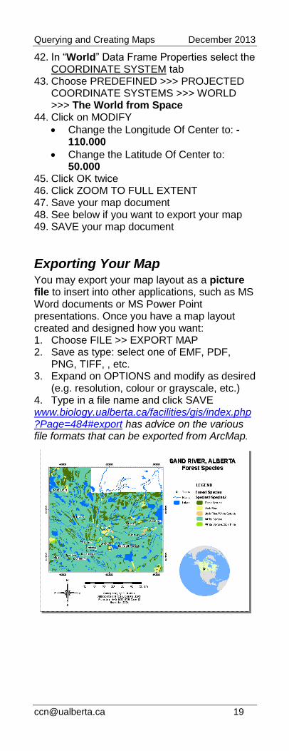
Exporting Your Map You may export your map layout as a picture file to insert into other applications, such as MS Word documents or MS Power Point presentations. Once you have a map layout created and designed how you want: 1. Choose FILE >> EXPORT MAP 2. Save as type: select one of EMF, PDF,
PNG, TIFF, , etc. 3. Expand on OPTIONS and modify as desired
(e.g. resolution, colour or grayscale, etc.) 4. Type in a file name and click SAVE www.biology.ualberta.ca/facilities/gis/index.php?Page=484#export has advice on the various file formats that can be exported from ArcMap.