gestra steam systems€¦ · · 2017-07-21gestra steam systems ba 210 ba 211 ... 530°c/986°f...
TRANSCRIPT
1
GESTRA Steam Systems
BA 210BA 211BAE 210BAE 211
Installation Instructions 818996-01Continuous Blowdown Valve Reaktomat®BA 210 (K), PN 250, DN 25BA 211 (K), PN 320, DN 25BAE 210 (K), PN 250, DN 25BAE 211 (K), PN 320, DN 25
ENEnglish
2
Inhalt
Important Notes
Usage for the intended purpose ..............................................................................................................5Safety note .............................................................................................................................................5Danger ...................................................................................................................................................5Attention .................................................................................................................................................6PED (Pressure Equipment Directive) ........................................................................................................6Machinery Directive (MD) ........................................................................................................................6ATEX (Atmosphère Explosible) .................................................................................................................6
Explanatory Notes
Scope of supply ......................................................................................................................................7Description .............................................................................................................................................8
Page
Technical Data
Name plate / marking .............................................................................................................................9Capacity chart for BA 210, BA 211, BAE 210, BAE 211 ..........................................................................10Capacity chart for BA 210 K, BA 211 K, BAE 210 K, BAE 211 K ..............................................................11
Installation
Danger .................................................................................................................................................15Attention ...............................................................................................................................................15Installation instructions .........................................................................................................................15Heat treatment of welds .......................................................................................................................15Mounting sample valve (if provided) ......................................................................................................15
Component Parts
BA 2... ..................................................................................................................................................12BAE 2... ................................................................................................................................................13Key .......................................................................................................................................................14
3
Contents - continued -
Electrical Connection
Danger .................................................................................................................................................16BAE 210 (K), BAE 211 (K) with standard actuator EF... ...........................................................................16BAE 210 (K), BAE 211 (K) with special actuator ....................................................................................16Factory setting BAE 210 (K), BAE 211 (K) .............................................................................................17
Commissioning Procedure
Danger .................................................................................................................................................18Attention ...............................................................................................................................................18BA 210 (K), BA 211 (K) ..........................................................................................................................19BAE 210 (K), BAE 211 (K) ......................................................................................................................19Calculating the amount of boiler blowdown ...........................................................................................19
Page
Emergency operation
BAE 210 (K), BAE 211 (K) ......................................................................................................................21
Operation
Danger .................................................................................................................................................20Attention ...............................................................................................................................................20BA 210 (K), BA 211 (K) ..........................................................................................................................20Purging .................................................................................................................................................20 BAE 210 (K), BAE 211 (K) ......................................................................................................................20
Maintenance
BA 210 (K), BAE 210 (K), BA 211 (K), BAE 211 (K) ..................................................................................21Danger .................................................................................................................................................21Attention ...............................................................................................................................................21Retightening stuffing box gland .............................................................................................................22BA 2..., BAE 2... Changing gland packing ..............................................................................................22BA 2..., BAE 2... Changing nozzle stem and nozzle insert ......................................................................23Tightening torques ................................................................................................................................24Tools .....................................................................................................................................................24
4
Contents - continued -
Page
Retrofitting
Danger .................................................................................................................................................25Retrofitting of an actuator .....................................................................................................................25List of parts for retrofitting ....................................................................................................................25
Spare Parts
Spare parts list .....................................................................................................................................26
Decommissioning
Danger .................................................................................................................................................27Disposal................................................................................................................................................27
Annex
Note on the Declaration of Conformity / Declaration by the Manufacturer ..............................................27
5
Important Notes
Usage for the intended purpose
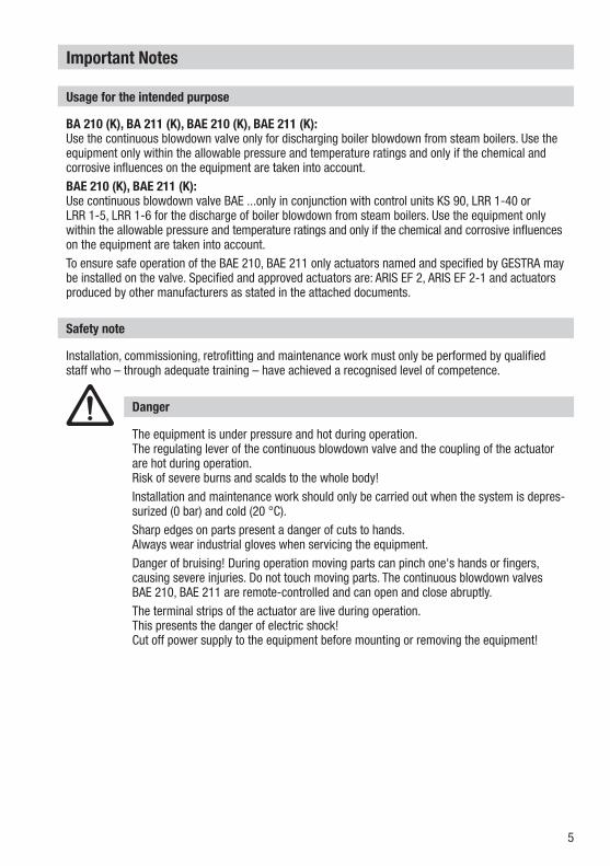
BA 210 (K), BA 211 (K), BAE 210 (K), BAE 211 (K):Use the continuous blowdown valve only for discharging boiler blowdown from steam boilers. Use the equipment only within the allowable pressure and temperature ratings and only if the chemical and corrosive influences on the equipment are taken into account.BAE 210 (K), BAE 211 (K):Use continuous blowdown valve BAE ...only in conjunction with control units KS 90, LRR 1-40 or LRR 1-5, LRR 1-6 for the discharge of boiler blowdown from steam boilers. Use the equipment only within the allowable pressure and temperature ratings and only if the chemical and corrosive influences on the equipment are taken into account.To ensure safe operation of the BAE 210, BAE 211 only actuators named and specified by GESTRA may be installed on the valve. Specified and approved actuators are: ARIS EF 2, ARIS EF 2-1 and actuators produced by other manufacturers as stated in the attached documents.
The equipment is under pressure and hot during operation. The regulating lever of the continuous blowdown valve and the coupling of the actuator are hot during operation.Risk of severe burns and scalds to the whole body!Installation and maintenance work should only be carried out when the system is depres-surized (0 bar) and cold (20 °C).Sharp edges on parts present a danger of cuts to hands.Always wear industrial gloves when servicing the equipment.Danger of bruising! During operation moving parts can pinch one's hands or fingers, causing severe injuries. Do not touch moving parts. The continuous blowdown valves BAE 210, BAE 211 are remote-controlled and can open and close abruptly.The terminal strips of the actuator are live during operation.This presents the danger of electric shock!Cut off power supply to the equipment before mounting or removing the equipment!
Danger
Installation, commissioning, retrofitting and maintenance work must only be performed by qualified staff who – through adequate training – have achieved a recognised level of competence.
Safety note
6
PED (Pressure Equipment Directive)
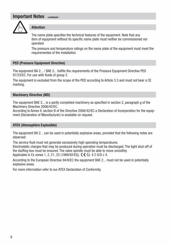
The equipment BA 2... / BAE 2... fulfills the requirements of the Pressure Equipment Directive PED 97/23/EC. For use with fluids of group 2. The equipment is excluded from the scope of the PED according to Article 3.3 and must not bear a CE marking.
Important Notes - continued -
ATEX (Atmosphère Explosible)
The equipment BA 2... can be used in potentially explosive areas, provided that the following notes are observed:The service fluid must not generate excessively high operating temperatures. Electrostatic charges that may be produced during operation must be discharged. The tight shut-off of the stuffing box must be ensured. The valve spindle must be able to move smoothly.Applicable in Ex zones 1, 2, 21, 22 (1999/92/EG), II 2 G/D c X.According to the European Directive 94/9/EC the equipment BAE 2... must not be used in potentially explosive areas.For more information refer to our ATEX Declaration of Conformity.
Machinery Directive (MD)
The equipment BAE 2... is a partly completed machinery as specified in section 2, paragraph g of the Machinery Directive 2006/42/EC.According to Annex II, section B of the Directive 2006/42/EC a Declaration of Incorporation for the equip-ment (Declaration of Manufacturer) is available on request.
The name plate specifies the technical features of the equipment. Note that any item of equipment without its specific name plate must neither be commissioned nor operated.The pressure and temperature ratings on the name plate of the equipment must meet the requirementes of the installation.
Attention
7
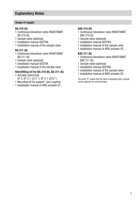
Scope of supply
BA 210 (K)1 Continuous blowdown valve REAKTOMAT BA 210 (K) 1 Sample valve (optional) 1 Installation manual GESTRA 1 Installation manual of the sample valve
BA 211 (K) 1 Continuous blowdown valve REAKTOMAT BA 211 (K) 1 Sample valve (optional) 1 Installation manual GESTRA 1 Installation manual of the sample valve
Retrofitting kit for BA 210 (K), BA 211 (K) 1 Actuator (electrical) EF 2, EF 2-1 (217 °), EF 2-1 (270 °) 1 Mounting kit for support / jaw coupling 1 Installation manual of ARIS actuator EF...
BAE 210 (K) 1 Continuous blowdown valve REAKTOMAT BAE 210 (K) 1 Sample valve (optional) 1 Installation manual GESTRA 1 Installation manual of the sample valve 1 Installation manual of ARIS actuator EF...
BAE 211 (K) 1 Continuous blowdown valve REAKTOMAT BAE 211 (K) 1 Sample valve (optional) 1 Installation manual GESTRA 1 Installation manual of the sample valve 1 Installation manual of ARIS actuator EF...
The suffix “K” means that the valve is equipped with a special nozzle (optional) for small flowrates.
Explanatory Notes
8
Explanatory Notes - continued -
Description
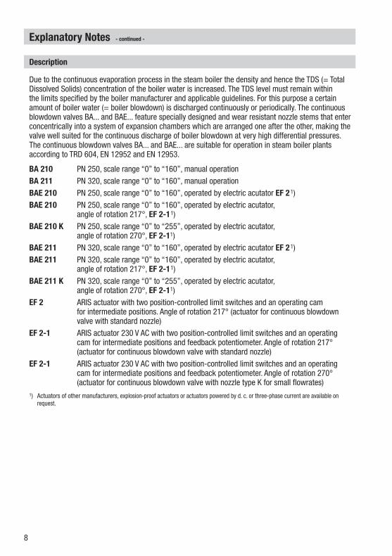
Due to the continuous evaporation process in the steam boiler the density and hence the TDS (= Total Dissolved Solids) concentration of the boiler water is increased. The TDS level must remain within the limits specified by the boiler manufacturer and applicable guidelines. For this purpose a certain amount of boiler water (= boiler blowdown) is discharged continuously or periodically. The continuous blowdown valves BA... and BAE... feature specially designed and wear resistant nozzle stems that enter concentrically into a system of expansion chambers which are arranged one after the other, making the valve well suited for the continuous discharge of boiler blowdown at very high differential pressures. The continuous blowdown valves BA... and BAE... are suitable for operation in steam boiler plants according to TRD 604, EN 12952 and EN 12953.
BA 210 PN 250, scale range “0” to “160”, manual operationBA 211 PN 320, scale range “0” to “160”, manual operationBAE 210 PN 250, scale range “0” to “160”, operated by electric acutator EF 21)BAE 210 PN 250, scale range “0” to “160”, operated by electric acutator,
angle of rotation 217°, EF 2-11)BAE 210 K PN 250, scale range “0” to “255”, operated by electric acutator,
angle of rotation 270°, EF 2-11)BAE 211 PN 320, scale range “0” to “160”, operated by electric acutator EF 21)BAE 211 PN 320, scale range “0” to “160”, operated by electric acutator,
angle of rotation 217°, EF 2-11)BAE 211 K PN 320, scale range “0” to “255”, operated by electric acutator,
angle of rotation 270°, EF 2-11)EF 2 ARIS actuator with two position-controlled limit switches and an operating cam
for intermediate positions. Angle of rotation 217° (actuator for continuous blowdown valve with standard nozzle)
EF 2-1 ARIS actuator 230 V AC with two position-controlled limit switches and an operating cam for intermediate positions and feedback potentiometer. Angle of rotation 217° (actuator for continuous blowdown valve with standard nozzle)
EF 2-1 ARIS actuator 230 V AC with two position-controlled limit switches and an operating cam for intermediate positions and feedback potentiometer. Angle of rotation 270° (actuator for continuous blowdown valve with nozzle type K for small flowrates)
1) Actuators of other manufacturers, explosion-proof actuators or actuators powered by d. c. or three-phase current are available on request.
9
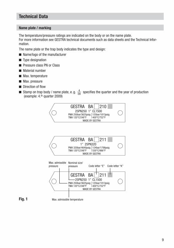
The temperature/pressure ratings are indicated on the body or on the name plate. For more information see GESTRA technical documents such as data sheets and the Technical Infor-mation.The name plate or the trap body indicates the type and design: Name/logo of the manufacturer Type designation Pressure class PN or Class Material number Max. temperature Max. pressure Direction of flow Stamp on trap body / name plate, e. g. specifies the quarter and the year of production (example: 4.th quarter 2009)
Technical Data
Fig. 1
Nominal size/pressure
Max. admissible pressure Code letter “E”
Max. admissible temperature
Name plate / marking
409
GESTRA BA 21025PN250 1” CL1500
PMA 250bar/3625psigTMA 120°C/248°F
125bar/1813psig400°C/752°F
MADE BY GESTRA
GESTRA BA 2111” 25PN320
PMA 320bar/4640psigTMA 120°C/248°F
124bar/1798psig530°C/986°F
MADE BY GESTRA
GESTRA BA 21125PN250 1” CL1500
PMA 250bar/3625psigTMA 120°C/248°F
125bar/1813psig400°C/752°F
MADE BY GESTRA
Code letter “K”
10
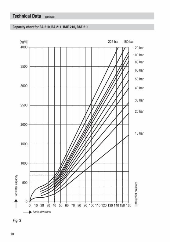
Fig. 2
Technical Data - continued -
Capacity chart for BA 210, BA 211, BAE 210, BAE 211
Skalenstriche
Heiß
was
serd
urch
satz
0 10 20 30 40 50 60 70 80 90 100 110 120 130 140 150 1600
1500
2000
500
1000
3000
4000
2500
3500
[kg/h]
10 bar
120 bar
20 bar
30 bar
40 bar
50 bar
60 bar
100 bar
80 bar
160 bar225 bar
Diffe
renz
druc
kDi
ffere
ntia
l pre
ssur
e
Hot w
ater
cap
acity
Scale divisions
11
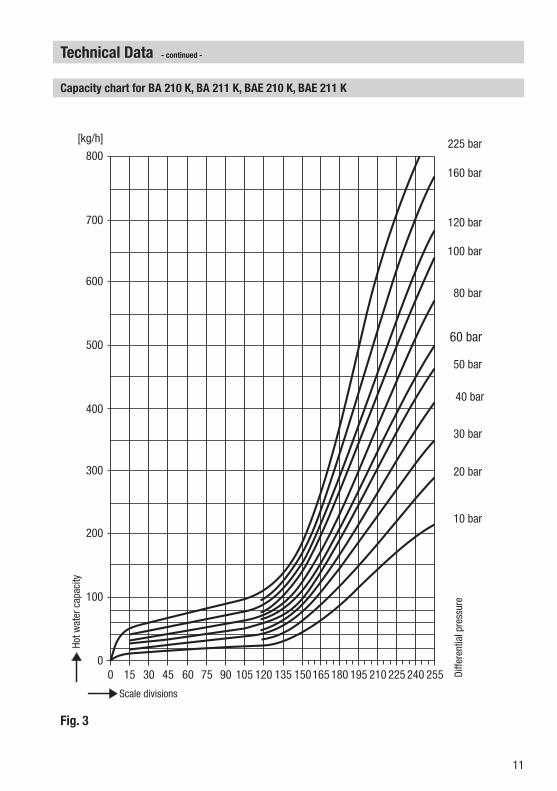
Fig. 3
Technical Data - continued -
Capacity chart for BA 210 K, BA 211 K, BAE 210 K, BAE 211 K
[kg/h]
0
300
400
100
200
600
800
500
700
Skalenstriche
Heiß
was
serd
urch
satz
Diffe
renz
druc
k
0 15 30 45 60 75 90 105 120 135 150165 180 255195 210 225 240
10 bar
120 bar
20 bar
30 bar
40 bar
50 bar
60 bar
100 bar
80 bar
160 bar
225 bar
Diffe
rent
ial p
ress
ure
Hot w
ater
cap
acity
Scale divisions
12
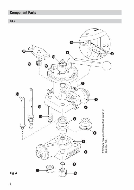
Fig. 4
Component Parts
BA 2...
2
e
b
d
1
a
f
g
h
c 4
3
5
6
7
8
9
0
2
∅ 5i
With
draw
al d
ista
nce
(mea
sure
d fro
m c
entre
of
pipe
): 35
0 m
m
13
k
l
m
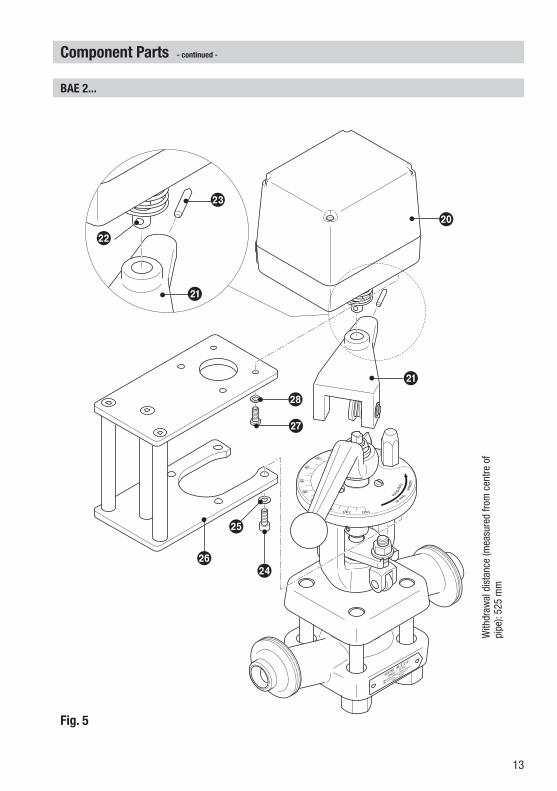
Component Parts - continued -
BAE 2...
Fig. 5
p
o
q
n
k
r
j
With
draw
al d
ista
nce
(mea
sure
d fro
m c
entre
of
pipe
): 52
5 m
m
14
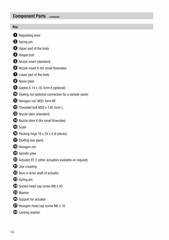
Component Parts - continued -
1 Regulating lever
2 Spring pin
3 Upper part of the body
4 Hinged bolt
5 Nozzle insert (standard)
6 Nozzle insert K (for small flowrates)
7 Lower part of the body
8 Name plate
9 Gasket A 14 x 18, form A (optional)
0 Sealing nut (optional connection for a sample valve)
a Hexagon nut, M20, form NF
b Threaded bolt M20 x 130, form L
c Nozzle stem (standard)
d Nozzle stem K (for small flowrates)
e Scale
f Packing rings 16 x 24 x 4 (6 pieces)
g Stuffing box gland
h Hexagon nut
i Spindle yoke
j Actuator EF 2 (other actuators available on request)
k Jaw coupling
l Bore in drive shaft of actuator
m Spring pin
n Socket-head cap screw M8 x 20
o Washer
p Support for actuator
q Hexagon-head cap screw M6 x 18
r Locking washer
Key

15
Installation
Installation instructions
1. Observe position of installation. The regulating lever 1 must be freely movable!2. Observe direction of flow. The arrow indicating the flow direction is on the valve body.3. Consider space required for servicing the trap. When the continuous blowdown valve is installed
observe the withdrawal distance for subsequent mounting or servicing of the actuator! Fig. 4, Fig. 54. Remove plastic plugs, they are only used as transit protection.5. Clean end connections.6.1 Install valve with releasable end connections (e. g. flanges).6.2 For equipment with socket-weld ends or butt-weld ends: Apply arc welding processes 111 and 141
according to ISO 4063 (or equivalent standard).
The continuous blowdown standpipe must be located below the low level mark and close to the steam oulet of the steam boiler!
Mount the (optional) sample valve only to the correct connection of the continuous blowdown valve, following the rules of the state of the technical art!
The nominal size of this equipment is designed for DN 25. Note that the admissible loads (forces, torques) acting on pipe connections with end connections larger than DN 25 are limited to the permissible pipe end loads of a size DN 25 device. Should the pipe end connection loads exceed this limit, take appropriate measures to provide additional support so as to protect the equipment.
Make sure that the inclination of the actuator does not exceed 90° when installed! Only qualified welders certified according to EN 287-1 (or equivalent national
standards) may weld continuous blowdown valves into lines.
Attention
Sharp edges on parts present a danger of cuts to hands.Always wear industrial gloves when servicing the equipment.
Danger
Heat treatment of welds
After welding the continuous blowdown valve in place a heat treatment of the welds is required (stress-relief annealing in compliance with the accredited state of the technical art).The heat treatment must be restricted to the immediate area of the weld.The internals of the blowdown valve need not be removed before the heat treatment.
Mounting sample valve (if provided)
1. Unscrew sealing nut 0. Remove gasket 9.2. Install sample valve in compliance with the accredited state of the technical art.
16
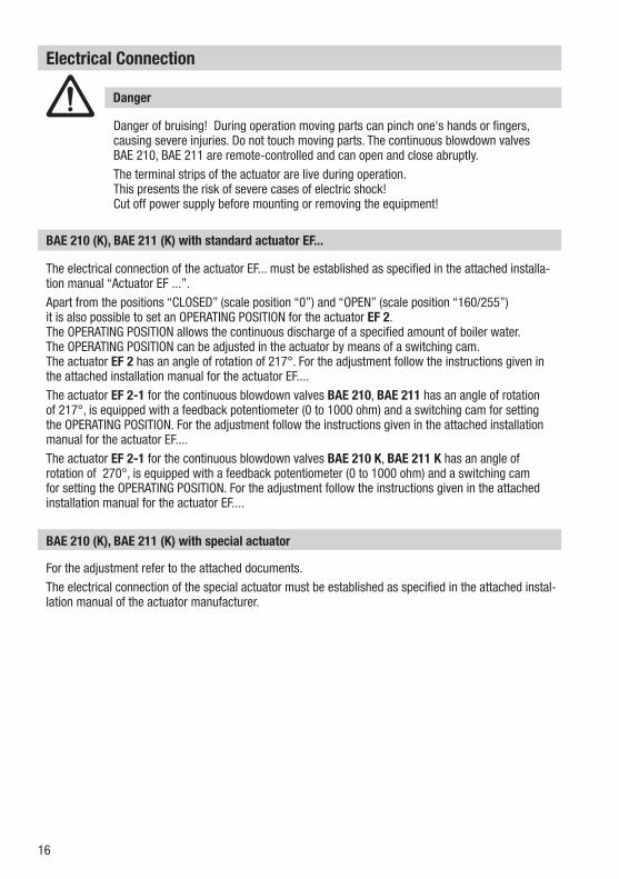
BAE 210 (K), BAE 211 (K) with standard actuator EF...
The electrical connection of the actuator EF... must be established as specified in the attached installa-tion manual “Actuator EF ...”.Apart from the positions “CLOSED” (scale position “0”) and “OPEN” (scale position “160/255”) it is also possible to set an OPERATING POSITION for the actuator EF 2. The OPERATING POSITION allows the continuous discharge of a specified amount of boiler water. The OPERATING POSITION can be adjusted in the actuator by means of a switching cam. The actuator EF 2 has an angle of rotation of 217°. For the adjustment follow the instructions given in the attached installation manual for the actuator EF.... The actuator EF 2-1 for the continuous blowdown valves BAE 210, BAE 211 has an angle of rotation of 217°, is equipped with a feedback potentiometer (0 to 1000 ohm) and a switching cam for setting the OPERATING POSITION. For the adjustment follow the instructions given in the attached installation manual for the actuator EF....The actuator EF 2-1 for the continuous blowdown valves BAE 210 K, BAE 211 K has an angle of rotation of 270°, is equipped with a feedback potentiometer (0 to 1000 ohm) and a switching cam for setting the OPERATING POSITION. For the adjustment follow the instructions given in the attached installation manual for the actuator EF....
Electrical Connection
Danger of bruising! During operation moving parts can pinch one's hands or fingers, causing severe injuries. Do not touch moving parts. The continuous blowdown valves BAE 210, BAE 211 are remote-controlled and can open and close abruptly. The terminal strips of the actuator are live during operation. This presents the risk of severe cases of electric shock! Cut off power supply before mounting or removing the equipment!
Danger
BAE 210 (K), BAE 211 (K) with special actuator
For the adjustment refer to the attached documents.The electrical connection of the special actuator must be established as specified in the attached instal-lation manual of the actuator manufacturer.
17
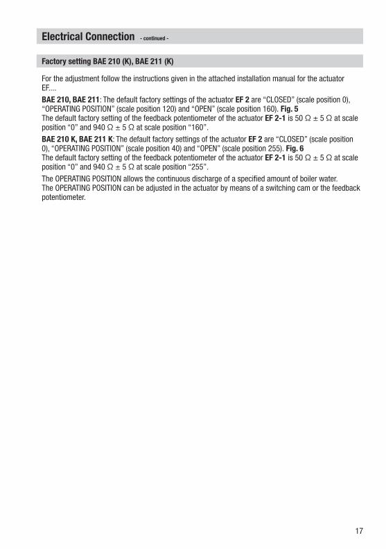
Factory setting BAE 210 (K), BAE 211 (K)
For the adjustment follow the instructions given in the attached installation manual for the actuator EF....BAE 210, BAE 211: The default factory settings of the actuator EF 2 are “CLOSED” (scale position 0), “OPERATING POSITION” (scale position 120) and “OPEN” (scale position 160). Fig. 5 The default factory setting of the feedback potentiometer of the actuator EF 2-1 is 50 Ω ± 5 Ω at scale position “0” and 940 Ω ± 5 Ω at scale position “160”.BAE 210 K, BAE 211 K: The default factory settings of the actuator EF 2 are “CLOSED” (scale position 0), “OPERATING POSITION” (scale position 40) and “OPEN” (scale position 255). Fig. 6 The default factory setting of the feedback potentiometer of the actuator EF 2-1 is 50 Ω ± 5 Ω at scale position “0” and 940 Ω ± 5 Ω at scale position “255”.The OPERATING POSITION allows the continuous discharge of a specified amount of boiler water. The OPERATING POSITION can be adjusted in the actuator by means of a switching cam or the feedback potentiometer.
Electrical Connection - continued -
18
Commissioning Procedure
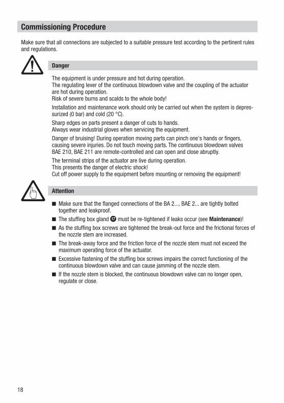
Make sure that all connections are subjected to a suitable pressure test according to the pertinent rules and regulations.
Make sure that the flanged connections of the BA 2..., BAE 2... are tightly bolted together and leakproof.
The stuffing box gland g must be re-tightened if leaks occur (see Maintenance)! As the stuffing box screws are tightened the break-out force and the frictional forces of
the nozzle stem are increased. The break-away force and the friction force of the nozzle stem must not exceed the
maximum operating force of the actuator. Excessive fastening of the stuffing box screws impairs the correct functioning of the
continuous blowdown valve and can cause jamming of the nozzle stem. If the nozzle stem is blocked, the continuous blowdown valve can no longer open,
regulate or close.
Attention
The equipment is under pressure and hot during operation. The regulating lever of the continuous blowdown valve and the coupling of the actuator are hot during operation.Risk of severe burns and scalds to the whole body!Installation and maintenance work should only be carried out when the system is depres-surized (0 bar) and cold (20 °C).Sharp edges on parts present a danger of cuts to hands.Always wear industrial gloves when servicing the equipment.Danger of bruising! During operation moving parts can pinch one's hands or fingers, causing severe injuries. Do not touch moving parts. The continuous blowdown valves BAE 210, BAE 211 are remote-controlled and can open and close abruptly.The terminal strips of the actuator are live during operation.This presents the danger of electric shock!Cut off power supply to the equipment before mounting or removing the equipment!
Danger
19
Commissioning - continued -
BA 210 (K), BA 211 (K)
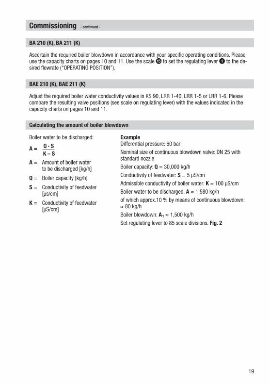
Ascertain the required boiler blowdown in accordance with your specific operating conditions. Please use the capacity charts on pages 10 and 11. Use the scale e to set the regulating lever 1 to the de-sired flowrate (“OPERATING POSITION”).
BAE 210 (K), BAE 211 (K)
Adjust the required boiler water conductivity values in KS 90, LRR 1-40, LRR 1-5 or LRR 1-6. Please compare the resulting valve positions (see scale on regulating lever) with the values indicated in the capacity charts on pages 10 and 11.
Calculating the amount of boiler blowdown
Boiler water to be discharged:
A = Q · S K – S
A = Amount of boiler water to be discharged [kg/h]
Q = Boiler capacity [kg/h]
S = Conductivity of feedwater [μs/cm]
K = Conductivity of feedwater [μS/cm]
Example Differential pressure: 60 bar Nominal size of continuous blowdown valve: DN 25 with standard nozzleBoiler capacity: Q = 30,000 kg/hConductivity of feedwater: S = 5 μS/cmAdmissible conductivity of boiler water: K = 100 μS/cmBoiler water to be discharged: A ≈ 1,580 kg/hof which approx.10 % by means of continuous blowdown: ≈ 80 kg/hBoiler blowdown: A1 ≈ 1,500 kg/hSet regulating lever to 85 scale divisions. Fig. 2
20
Operation
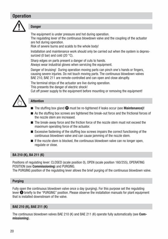
Fully open the continuous blowdown valve once a day (purging). For this purpose set the regulating lever 1 briefly to the “PURGING” position. Please observe the installation manuals for plant equipment that is installed downstream of the valve.
Positions of regulating lever: CLOSED (scale position 0), OPEN (scale position 160/255), OPERATING POSITION (see Commissioning) and PURGING. The PURGING position of the regulating lever allows the brief purging of the continuous blowdown valve.
The continuous blowdown valves BAE 210 (K) and BAE 211 (K) operate fully automatically (see Com-missioning).
BAE 210 (K), BAE 211 (K)
BA 210 (K), BA 211 (K)
Purging
The equipment is under pressure and hot during operation. The regulating lever of the continuous blowdown valve and the coupling of the actuator are hot during operation.Risk of severe burns and scalds to the whole body!Installation and maintenance work should only be carried out when the system is depres-surized (0 bar) and cold (20 °C).Sharp edges on parts present a danger of cuts to hands.Always wear industrial gloves when servicing the equipment.Danger of bruising! During operation moving parts can pinch one's hands or fingers, causing severe injuries. Do not touch moving parts. The continuous blowdown valves BAE 210, BAE 211 are remote-controlled and can open and close abruptly.The terminal strips of the actuator are live during operation.This presents the danger of electric shock!Cut off power supply to the equipment before mounting or removing the equipment!
Danger
The stuffing box gland g must be re-tightened if leaks occur (see Maintenance)! As the stuffing box screws are tightened the break-out force and the frictional forces of
the nozzle stem are increased. The break-away force and the friction force of the nozzle stem must not exceed the
maximum operating force of the actuator. Excessive fastening of the stuffing box screws impairs the correct functioning of the
continuous blowdown valve and can cause jamming of the nozzle stem. If the nozzle stem is blocked, the continuous blowdown valve can no longer open,
regulate or close.
Attention
21
Emergency operation
BAE 210 (K), BAE 211 (K)
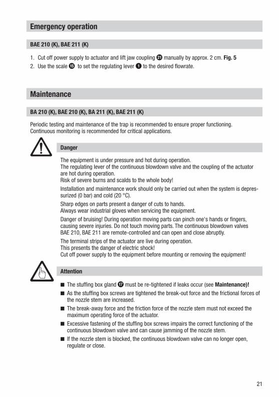
1. Cut off power supply to actuator and lift jaw coupling k manually by approx. 2 cm. Fig. 52. Use the scale e to set the regulating lever 1 to the desired flowrate.
Maintenance
The stuffing box gland g must be re-tightened if leaks occur (see Maintenance)! As the stuffing box screws are tightened the break-out force and the frictional forces of
the nozzle stem are increased. The break-away force and the friction force of the nozzle stem must not exceed the
maximum operating force of the actuator. Excessive fastening of the stuffing box screws impairs the correct functioning of the
continuous blowdown valve and can cause jamming of the nozzle stem. If the nozzle stem is blocked, the continuous blowdown valve can no longer open,
regulate or close.
Periodic testing and maintenance of the trap is recommended to ensure proper functioning.Continuous monitoring is recommended for critical applications.
The equipment is under pressure and hot during operation. The regulating lever of the continuous blowdown valve and the coupling of the actuator are hot during operation.Risk of severe burns and scalds to the whole body!Installation and maintenance work should only be carried out when the system is depres-surized (0 bar) and cold (20 °C).Sharp edges on parts present a danger of cuts to hands.Always wear industrial gloves when servicing the equipment.Danger of bruising! During operation moving parts can pinch one's hands or fingers, causing severe injuries. Do not touch moving parts. The continuous blowdown valves BAE 210, BAE 211 are remote-controlled and can open and close abruptly.The terminal strips of the actuator are live during operation.This presents the danger of electric shock!Cut off power supply to the equipment before mounting or removing the equipment!
Danger
BA 210 (K), BAE 210 (K), BA 211 (K), BAE 211 (K)
Attention
22
Maintenance - continued -
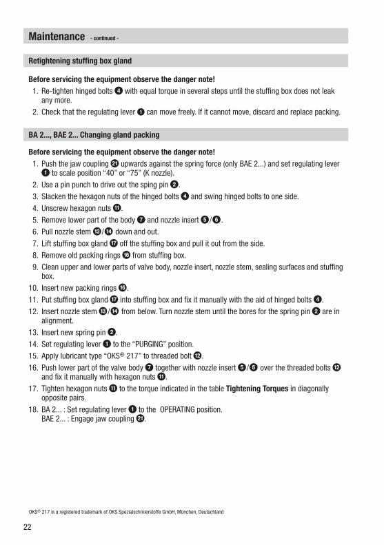
Before servicing the equipment observe the danger note! 1. Push the jaw coupling k upwards against the spring force (only BAE 2...) and set regulating lever
1 to scale position “40” or “75” (K nozzle). 2. Use a pin punch to drive out the sping pin 2. 3. Slacken the hexagon nuts of the hinged bolts 4 and swing hinged bolts to one side. 4. Unscrew hexagon nuts a. 5. Remove lower part of the body 7 and nozzle insert 5/6 . 6. Pull nozzle stem c/d down and out. 7. Lift stuffing box gland g off the stuffing box and pull it out from the side. 8. Remove old packing rings f from stuffing box. 9. Clean upper and lower parts of valve body, nozzle insert, nozzle stem, sealing surfaces and stuffing
box.10. Insert new packing rings f.11. Put stuffing box gland g into stuffing box and fix it manually with the aid of hinged bolts 4.12. Insert nozzle stem c/d from below. Turn nozzle stem until the bores for the spring pin 2 are in
alignment.13. Insert new spring pin 2.14. Set regulating lever 1 to the “PURGING” position. 15. Apply lubricant type “OKS® 217” to threaded bolt b.16. Push lower part of the valve body 7 together with nozzle insert 5/6 over the threaded bolts b
and fix it manually with hexagon nuts a. 17. Tighten hexagon nuts a to the torque indicated in the table Tightening Torques in diagonally
opposite pairs.18. BA 2... : Set regulating lever 1 to the OPERATING position.
BAE 2... : Engage jaw coupling k.
BA 2..., BAE 2... Changing gland packing
Retightening stuffing box gland
Before servicing the equipment observe the danger note! 1. Re-tighten hinged bolts 4 with equal torque in several steps until the stuffing box does not leak
any more. 2. Check that the regulating lever 1 can move freely. If it cannot move, discard and replace packing.
OKS® 217 is a registered trademark of OKS Spezialschmierstoffe GmbH, München, Deutschland
23
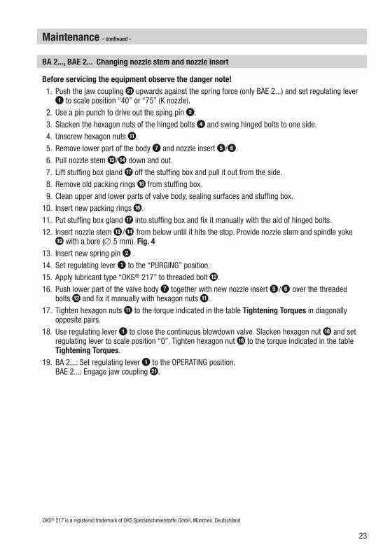
Maintenance - continued -
Before servicing the equipment observe the danger note! 1. Push the jaw coupling k upwards against the spring force (only BAE 2...) and set regulating lever
1 to scale position “40” or “75” (K nozzle). 2. Use a pin punch to drive out the sping pin 2. 3. Slacken the hexagon nuts of the hinged bolts 4 and swing hinged bolts to one side. 4. Unscrew hexagon nuts a. 5. Remove lower part of the body 7 and nozzle insert 5/6. 6. Pull nozzle stem c/d down and out. 7. Lift stuffing box gland g off the stuffing box and pull it out from the side. 8. Remove old packing rings f from stuffing box. 9. Clean upper and lower parts of valve body, sealing surfaces and stuffing box. 10. Insert new packing rings f.11. Put stuffing box gland g into stuffing box and fix it manually with the aid of hinged bolts.12. Insert nozzle stem c/d from below until it hits the stop. Provide nozzle stem and spindle yoke
i with a bore (∅ 5 mm). Fig. 413. Insert new spring pin 2 .14. Set regulating lever 1 to the “PURGING” position. 15. Apply lubricant type “OKS® 217” to threaded bolt b. 16. Push lower part of the valve body 7 together with new nozzle insert 5/6 over the threaded
bolts b and fix it manually with hexagon nuts a.17. Tighten hexagon nuts a to the torque indicated in the table Tightening Torques in diagonally
opposite pairs.18. Use regulating lever 1 to close the continuous blowdown valve. Slacken hexagon nut h and set
regulating lever to scale position “0”. Tighten hexagon nut h to the torque indicated in the table Tightening Torques.
19. BA 2...: Set regulating lever 1 to the OPERATING position. BAE 2...: Engage jaw coupling k.
BA 2..., BAE 2... Changing nozzle stem and nozzle insert
OKS® 217 is a registered trademark of OKS Spezialschmierstoffe GmbH, München, Deutschland
24
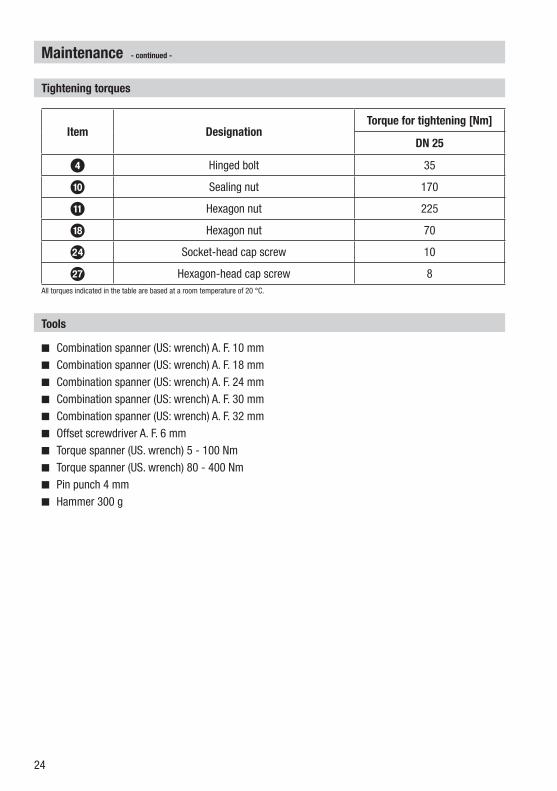
Combination spanner (US: wrench) A. F. 10 mm Combination spanner (US: wrench) A. F. 18 mm Combination spanner (US: wrench) A. F. 24 mm Combination spanner (US: wrench) A. F. 30 mm Combination spanner (US: wrench) A. F. 32 mm Offset screwdriver A. F. 6 mm Torque spanner (US. wrench) 5 - 100 Nm Torque spanner (US. wrench) 80 - 400 Nm Pin punch 4 mm Hammer 300 g
Tools
Tightening torques
Item DesignationTorque for tightening [Nm]
DN 25
4 Hinged bolt 35
0 Sealing nut 170
a Hexagon nut 225
h Hexagon nut 70
n Socket-head cap screw 10
q Hexagon-head cap screw 8All torques indicated in the table are based at a room temperature of 20 °C.
Maintenance - continued -
25
Retrofitting
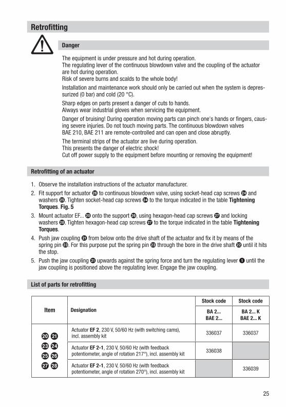
Retrofitting of an actuator
1. Observe the installation instructions of the actuator manufacturer.2. Fit support for actuator p to continuous blowdown valve, using socket-head cap screws n and
washers o. Tighten socket-head cap screws n to the torque indicated in the table Tightening Torques. Fig. 5
3. Mount actuator EF... j onto the support p, using hexagon-head cap screws q and locking washers r. Tighten hexagon-head cap screws q to the torque indicated in the table Tightening Torques.
4. Push jaw coupling k from below onto the drive shaft of the actuator and fix it by means of the spring pin m. For this purpose put the spring pin m through the bore in the drive shaft l until it hits the stop.
5. Push the jaw coupling k upwards against the spring force and turn the regulating lever 1 until the jaw coupling is positioned above the regulating lever. Engage the jaw coupling.
List of parts for retrofitting
Item Designation
Stock code Stock code
BA 2... BAE 2...
BA 2... KBAE 2... K
j km no pq r
Actuator EF 2, 230 V, 50/60 Hz (with switching cams), incl. assembly kit 336037 336037
Actuator EF 2-1, 230 V, 50/60 Hz (with feedbackpotentiometer, angle of rotation 217°), incl. assembly kit 336038
Actuator EF 2-1, 230 V, 50/60 Hz (with feedbackpotentiometer, angle of rotation 270°), incl. assembly kit 336039
The equipment is under pressure and hot during operation. The regulating lever of the continuous blowdown valve and the coupling of the actuator are hot during operation.Risk of severe burns and scalds to the whole body!Installation and maintenance work should only be carried out when the system is depres-surized (0 bar) and cold (20 °C).Sharp edges on parts present a danger of cuts to hands.Always wear industrial gloves when servicing the equipment.Danger of bruising! During operation moving parts can pinch one's hands or fingers, caus-ing severe injuries. Do not touch moving parts. The continuous blowdown valves BAE 210, BAE 211 are remote-controlled and can open and close abruptly.The terminal strips of the actuator are live during operation.This presents the danger of electric shock!Cut off power supply to the equipment before mounting or removing the equipment!
Danger
26
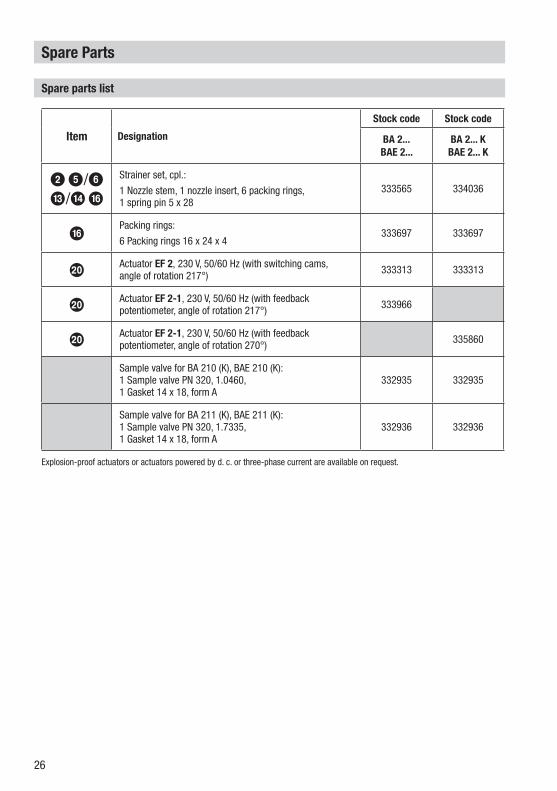
Spare Parts
Spare parts list
Item Designation
Stock code Stock code
BA 2... BAE 2...
BA 2... KBAE 2... K
2 5/6 c/d f
Strainer set, cpl.:
1 Nozzle stem, 1 nozzle insert, 6 packing rings, 1 spring pin 5 x 28
333565 334036
f Packing rings:
6 Packing rings 16 x 24 x 4 333697 333697
jActuator EF 2, 230 V, 50/60 Hz (with switching cams,angle of rotation 217°) 333313 333313
jActuator EF 2-1, 230 V, 50/60 Hz (with feedbackpotentiometer, angle of rotation 217°) 333966
jActuator EF 2-1, 230 V, 50/60 Hz (with feedbackpotentiometer, angle of rotation 270°) 335860
Sample valve for BA 210 (K), BAE 210 (K):1 Sample valve PN 320, 1.0460, 1 Gasket 14 x 18, form A
332935 332935
Sample valve for BA 211 (K), BAE 211 (K):1 Sample valve PN 320, 1.7335, 1 Gasket 14 x 18, form A
332936 332936
Explosion-proof actuators or actuators powered by d. c. or three-phase current are available on request.
27
Decommissioning
Disposal
For the disposal of the equipment observe the pertinent legal regulations concerning waste disposal.
For details on the conformity assessment according to the European Directives see our Declaration of Conformity or our Declaration of Manufacturer.The current Declaration of Conformity / Declaration of Manufacturer are available in the Internet under www.gestra./de/xxx or can be requested from us.
Note on the Declaration of Conformity / Declaration by the Manufacturer
Annex
The equipment is under pressure and hot during operation. The regulating lever of the continuous blowdown valve and the coupling of the actuator are hot during operation.Risk of severe burns and scalds to the whole body!Installation and maintenance work should only be carried out when the system is depres-surized (0 bar) and cold (20 °C).Sharp edges on parts present a danger of cuts to hands.Always wear industrial gloves when servicing the equipment.Danger of bruising! During operation moving parts can pinch one's hands or fingers, causing severe injuries. Do not touch moving parts. The continuous blowdown valves BAE 210, BAE 211 are remote-controlled and can open and close abruptly.The terminal strips of the actuator are live during operation.This presents the danger of electric shock!Cut off power supply to the equipment before mounting or removing the equipment!
Danger
28818996-01/11-2010cm (808797-01) · GESTRA AG · Bremen · Printed in Germany
Agencies all over the world:
www.gestra.de
GESTRA AGMünchener Straße 77 28215 BremenGermanyTelefon +49 421 3503-0 Telefax +49 421 3503-393E-mail [email protected] www.gestra.de