german volkswagen - ibiblio · f. steering gear. steering wheel and steering mechanism are of the...
TRANSCRIPT

WAR DEPARTMENT TECHNICGL MANUAL
Suecd. Late TM E9-803 E' -gO3
GERMAN
VOLKSWAGEN
REGRADED UNCLASSIFIED BY^AUTovTY OF DOD DIR. 5200. 1 RBY I ___ __ ON L Z O-
WAR DEPARTMENT 6 JUNE 1944
_ DISSEMINATION OF RESTRICTED MATTER-.The information contained in restricted documents and the essential char-acteristics of restricted materiel may be given to any person known to be inthe service of the United States and to persons of undoubted loyalty anddiscretion who are cooperating in Government work, but will not be com-municated to the public or to the press except by authorized military publicrelations agencies. (See also paragraph 23, AR 380-5, 15 March 1944.)

WAR DEPARTMENTWashington 25, D. C., 6 June 1944
TM E9-803, German Volkswagen, is published for the informationand guidance of all concerned.
FA.G. 300.7 (15 Mar 44) ]
LO.O.M. 461/Raritan Ars. (7 Jun 44)-R
BY ORDER OF THE SECRETARY OF WAR:
G. C. MARSHALL,Chief of Staff.
OFFICIAL:
J. A. ULIO,Major General,
The Adjutant General.
DISTRIBUTION: As prescribed in par. 9.a., FM 21-6: X.
(For explanation of symbol, see FM 21-6.)

TM E9-803
CONTENTS
PART ONE-INTRODUCTION
Paragraphs Pages
SECTION I. General .................................... 1- 2 1- 2
II. Description and data .............. 3- 5 2- 6
III. Tools, parts, and accessories.. 6- 7 6- 7
PART TWO-OPERATING INSTRUCTIONS
SECTION IV. Controls and instruments........ 8- 9 8- 11
V. Operation under ordinaryconditions .......................... 10- 12 12- 13
VI. Operation under unusualconditions ............................ 13- 17 13- 18
PART THREE-MAINTENANCE INSTRUCTIONS
SECTION VII. Lubrication ............................ 18- 19 19- 23
VIII. First echelon preventivemaintenance services .......... 20- 24 23- 32
IX. Second echelon preventivemaintenance ........................ 25 32- 47
X. Trouble shooting .................... 26- 43 48- 60
XI. Engine description and main-tenance in vehicle ................ 44- 49 60- 68
XII. Engine, removal and instal-lation .................................. 50- 52 69- 72
XIII. Clutch .................................... 53- 57 72- 75
XIV. Engine lubrication system ..... 58- 62 76- 81
XV. Fuel and air intake andexhaust systems .................. 63- 69 81- 87
XVr. Cooling system ....................... 70- 71 87- 88
XVII. Ignition system ....................... 72- 76 88- 91-
XVIII. Starting and generatingsystem ................................ 77- 80 91- 94
XIX. Battery and lighting systems 81- 88 94- 99

TM -E9-803
CONTENTS-Contd.
Paragraphs Pages
SECTION XX. Transmission and differential 89- 90 99-102
XXI. Rear axle ................................ 91- 93 103-105
XXII. Front axle ............................. 94-100 106-111
XXIII. Service and parking brakes .... 101-103 111-117
XXIV. Steering system ...................... 104-107 117-120
XXV. Tires, tubes, and wheels ........ 108-110 121-123
XXVI. Shock absorbers ...................... 111-113 123-124
XXVII. Instrument panel andinstruments ........................ 114-115 125
XXVIII. Body and frame...................... 116-125 125-127
APPENDIX
SECTION XXIX. Shipment and temporarystorage ................................ 126-128 128-132
XXX References .............................. 129-131 133-134
INDEX .................................................... ........................... 135-140

TM E9-8031-2
PART ONE-INTRODUCTION
Section I
GENERAL
1. SCOPE.
a. These instructions are published for the information andguidance of the personnel to whom this equipment is assigned. Theycontain information on the operation and maintenance of the GermanVolkswagen as well as descriptions of the major units and their func-tions in relation to the other components of the vehicle.
b. This manual has the following arrangement.
(1) Part One, Introduction, contains description and data.
(2) Part Two, Operating Instructions, contains instructions forthe operation of the vehicle, with description and location of the con-trols and instruments.
(3) Part Three, Maintenance Instructions, contains informationneeded for the performance of the scheduled lubrication and pre-ventive maintenance services, and instructions for maintenance opera-tions which can ordinarily be performed by using organizations (firstand second echelons).
(4) The Appendix contains instructions for shipment and limitedstorage, and a list of references which may provide helpful informa-tion concerning operation or maintenance.
c. The operations described in this manual are based on theavailability of necessary parts, accessories, and tools. Conditions willarise in which the items referred to in the manual are not availablesince they cannot be requisitioned through usual channels. In thesecases,individual initiative must be resorted to when repairs are required.
2. RECORDS.
a. Forms and records which may be provided for use in per-forming prescribed operations are listed below with brief explanationsof each. In case of Volkswagen, use of these forms will be governedby tactical situation and extent to which vehicle is employed.
(1) STANDARD FORM No. 26, DRIVER'S REPORT-ACCIDENT,MOTOR TRANSPORTATION. One copy of this form should be keptwith the vehicle at all times. In case of an accident resulting ininjury or property damage, it should be filled out by the driver on thespot, or as promptly as practical thereafter.
(2) WAR DEPARTMENT FORM No. 48, DRIVER'S TRIP TICKETAND PREVENTIVE MAINTENANCE SERVICE RECORD. This form, prop-
1

TM- E9-8032-3
GERMAN VOLKSWAGEN
erly executed, is furnished to the driver when his vehicle is dispatchedon non-tactical missions. The driver and the official user of thevehicle complete, in detail, appropriate parts of this form. Theseforms need not be issued for vehicles in convoy or on tactical mis-sions. The reverse side of this form contains the driver's daily andweekly preventive maintenance service reminder schedule.
(3) W.D., A.G.O. FORM NO. 6, DuTY ROSTER. This form,slightly modified, is used for scheduling and maintaining a record ofvehicle maintenance operations. It may be used for lubricationrecords.
(4) W.D., A.G.O. FORM No. 461, PREVENTIVE MAINTENANCESERVICE AND TECHNICAL INSPECTION WORK SHEET FOR WHEELEDAND HALF-TRACK VEHICLES. This form is used for all 1,000-mile(monthly) and 6,000-mile (semiannual) maintenance services andall technical inspections performed on wheeled or half-track vehicles.
Section II
DESCRIPTION AND DATA3. DESCRIPTION.
a. General. The Volkswagen is a four-wheeled, rubber-tired,rear axle drive personnel carrier and reconnaissance car, comparablein purpose and size to the American U4-ton 4x4 truck. No propellershaft, as such, is used; the engine, transmission, and differential com-prise a unit structure which is secured to the floor at the extreme rearend of the vehicle. Access to the engine is provided by a hinged door atthe rear of the body. The vehicle has no frame. Instead, a base stamp-ing comprising the floor of the vehicle is ribbed and provided with acentral tunnel to give desired stiffness, to form the foundation of thevehicle. The main fuel tank is located under the front body panel onthe right-hand side of the vehicle. The spare tire is carried on top ofthe front body panel.
b. Engine. The engine is an air-cooled, four-cylinder, four-cycle,horizontally-opposed type. Intake and exhaust valves are located inthe cylinder head and are operated by conventional rocker arms andpush rods.
c. Transmission. The transmission is the selective, sliding-geartype. Four speeds forward and one reverse are available. Differingfrom American vehicles, no direct drive is used. The fourth speedforward is an overdrive, having a ratio of 0.80 to 1. A detailed descrip-tion of the transmission is contained in section XX.
2

TM E9-8033
DESCRIPTION AND DATA
e -
I .1
0G_ 0
O
'-it
Z

rM E9-8033
GERMAN VOLKSWAGEN
~~~~~~~~~o C:4
· o i a~~~~
I.
4
4~~~~
! t,' :% Ji'' ~ ~ ~
:l
pl:·; :·~dS~B~~rP - r~ l
TM E9-8033-4
DESCRIPTION AND DATA
d. Differential. A positive locking differential is used in placeof spider gears. Whenever excessive friction is built up, the differentiallocks, thereby transmitting torque equally to the two driving wheels.A detailed description of the differential is contained in section XX.
e. Suspension. All wheels are independently sprung. The twofront wheels are sprung on pairs of torsion rods mounted transverselyon the vehicle, with the wheel kingpins being supported on a parallelo-gram linkage. The two rear wheels are stabilized laterally from thedifferential housing, and oscillate vertically about centers of the uni-versal joints which are attached to the sides of the differential housing.Suspension of the rear wheels is by torsion arms attached to each endof a torsion rod mounted transversely on the vehicle.
f. Steering Gear. Steering wheel and steering mechanism areof the conventional type commonly used in American vehicles.
g. Braking System. Service brakes operate on all four wheels.These are mechanical brakes, actuated by cables attached to the footbrake pedal. The parking brake, through the same system of cables,also operates the service brakes on all four wheels.
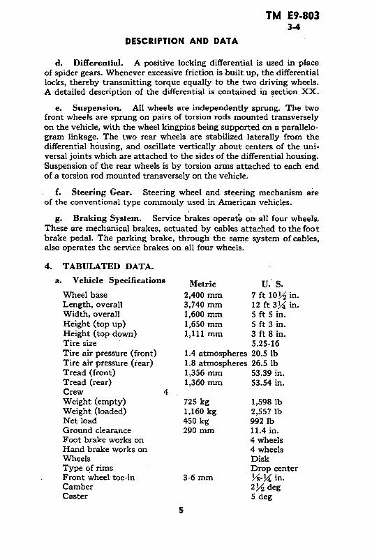
4. TABULATED DATA.
a. Vehicle Specifications Metric U. S.
Wheel base 2,400 mm 7 ft 10/ in.Length, overall 3,740 mm 12 ft 3Y4 in.Width, overall 1,600 mm 5 ft 5 in.Height (top up) 1,650 mm 5 ft 3 in.Height (top down) 1,111 mm 3 ft 8 in.Tire size 5.25-16Tire air pressure (front) 1.4 atmospheres 20.5 lbTire air pressure (rear) 1.8 atmospheres 26.5 lbTread (front) 1,356 mm 53.39 in.Tread (rear) 1,360 mm 53.54 in.Crew 4Weight (empty) 725 kg 1,598 lbWeight (loaded) 1,160 kg 2,557 lbNet load 450 kg 992 lbGround clearance 290 mm 11.4 in.Foot brake works on 4 wheelsHand brake works on 4 wheelsWheels DiskType of rims Drop centerFront wheel toe-in 3-6 mm Y/-_ in.Camber 2 2 degCaster 5 deg
5

TM E9-8034-7
GERMAN VOLKSWAGEN
b. Performance.Mtrlc U. S.
Minimum speed 3 kmph 1.8 mphMaximum speed 80 kmph 49.7 mphClimbing ability in loose sand 40 pct.Climbing ability on the road 45 pct.Fording depth (without
wetting engine) 450 mm 17.7 in.Operating radius 400-450 km 250-280 miles
c. Capacities.
Main gas tank 30 liters 7.925 galNormal fuel consumption 8 liters per 100
kilometers 30 mpg (approx)Transmission and differential
for lubricant change 2.5 liters 2.6 qtFor filling after overhaul 3.0 liters 3.1 qtEngine
For oil change 2.5 liters 2.6 qtFor filling after overhaul 3.0 liters 3.1 qt
Steering mechanism 0.25 liters X/ pt
5. CONVERSION TABLE.
Metric to U. S. U. S. to Metric1 millimeter equals 0.0394 inches 1 inch equals 25.4 millimeters1 liter equals 0.264 gallons 1 gallon equals 3.785 liters1 kilogram equals 2.205 pounds 1 pound equals 0.454 kilograms1 kilometer equals 0.621 miles 1 mile equals 1.609 kilometers
Section III
TOOLS, PARTS. AND ACCESSORIES
6. TOOLS.
a. All maintenance operations listed in this manual can be per-formed with standard tools available to the first and second echelonmaintenance organizations. Open-end and socket wrenches used mustbe in %4-inch sizes to properly fit the metric scale of bolt and nutsizes.
7. PARTS AND ACCESSORIES.
a. Since this materiel is of German manufacture, replacement ofvarious units with corresponding units of American manufacture islimited to minor parts which can be adapted for use on this vehicle by
6

TM E9-8037
TOOLS, PARTS, AND ACCESSORIES
improvising mounting facilities. Examples of such replacement unitsheadlights, coil, wiring, and some of the instruments in the instrumentpanel. Otherwise, parts replacement will have to be handled by can-nibalization.
b. Many vehicles will be found from which the tools and equip-ment have been removed, lost, or damaged. These may be replaced bycannibalization or by requisition of comparable American equipmentthrough usual channels. Below is a suggested list of American equip-ment which will be found valuable and useful for proper operation andmaintenance of the vehicle. This list is for information only and is notto be used as a basis for requisition.
Tools and Equipment Federal Stock No.
Ax, chopping, single-bit ................................................... 41-A-1277Extinguisher, fire ........................... ............. 58-E-202Gage, tire pressure ............................................................ 8-G-615Gun, lubr., hand-type ..... .......................... 41-G-1330-60Oiler, straight spout, 1/2-pt ......... ......................... 13-0-1530Pliers, combination, slip joint, 6-in ................................... 41-P-1650Pump, tire, w/chuck .......................... ....... 8-P-5000Screwdriver, common, 6-in. .................................... 41-S-1104Shovel, D-handle, rd. pt ............ .......................... 41-S-3170Wrench, adjustable, automobile type, 11-in ...................... 41-W-448Wrench, adjustable, crescent type, 8-in ............................ 41-W-486
7
TM E9-8038
GERMAN VOLKSWAGEN
U _o~~~~~~~~~
0 ~~z> ~~o~0 0
zS t
: Z U M _ Z U 1
D 0 > oo o o 0 o ZI I I MO I I I I I OI I I I I I a
Al u 0-o -M L -= > x
o~~ -o°Y D
1,
4 4.
a~~~~~~~~~~~~~.~~~O <<: rs ~
8

TM E9.8038
PART TWO-OPERATING INSTRUCTIONS
Section IV
CONTROLS AND INSTRUMENTS
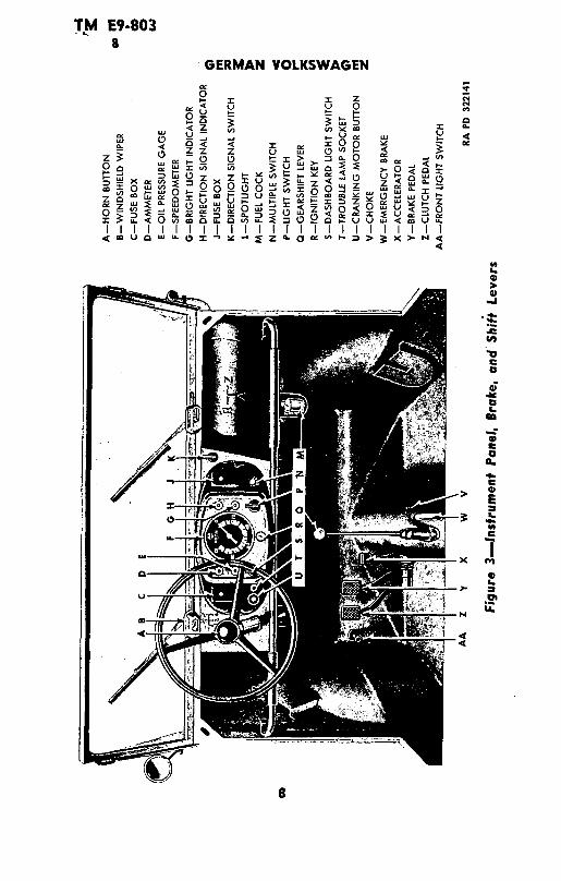
8. CONTROLS.
a. Ignition Switch. The ignition switch is located at the lowercenter of the instrument panel. A key is furnished to operate the switch.When the key is inserted and turned, the switch serves to close elec-trical circuits between the battery and ignition coil, direction indica-tor light, oil pressure light, and dash light switch. All the other circuitsare opened and closed by their respective switches.
b. Horn Button. The horn button is located in the hub of thesteering wheel. When the button is depressed, it closes the circuit be-tween the source of electrical power and the horn, and thus actuatesthe horn.
c. Cranking Motor Button. The cranking motor button is locatedon the extreme lower left side of the instrument panel. When thecranking motor button is depressed, it closes the electrical circuit be-tween the cranking motor and battery. The cranking motor rotatesand, through a series of gears, rotates the engine crankshaft.
d. Fuse Boxes. Two rectangular fuse boxes, one at each end,are located on the instrtument panel. Most of the electrical circuits inthe vehicle pass through one, or the other, of these boxes. In the eventa circuit is shorted or overloaded, the fuse burns out. This opens thecircuit and prevents damage to any item of equipment, or injury topersonnel.
e. Trouble Lamp Socket. This socket provides an electricaloutlet in which a corded lamp may be plugged, thus providing portableillumination. The socket is located just to the right of the crankingmotor button.
f. Dash Light Switch. The dash light switch is located onthe instrument panel to the right of the trouble lamp socket. Whenturned on, it closes the circuit between the source of electrical powerand the dash light, thus turning on the dash light.
g. Light Switch. The light switch is located on the instrumentpanel just beneath the bright light indicator. When the light switch isturned on it operates the service headlights and service tail and stoplight.
h. Multiple Switch. The multiple switch is located just to theright of the light switch. The multiple switch has three positions: one
9

TM E9-8038
GERMAN VOLKSWAGEN
"OFF"; one to turn on the blackout driving light and the blackouttail and stop light; and one to close the circuit to the headlight switch.
i. Direction Signal Switch. The direction signal switch is lo-cated at the extreme right-hand top side of the instrument panel. Itcontrols the two direction signals located on the outer ends of the wind-shield. When the switch is turned to the left, the left direction signal isextended, and when the switch is turned to the right, the right direc-tion signal is extended. "OFF" position of the switch is vertical.
j. Fuel Cock. The fuel cock is located at the fuel strainerbeneath the fuel tank. Closing the cock shuts off the flow of fuel fromthe fuel tank to the carburetor on the engine.
k. Foot Dimmer Switch. The foot dimmer switch, located onthe upward slope of the floor and convenient to the driver's left foot,is used to control the output of the front headlights. Stepping down onthe switch operates it.
1. Clutch Pedal. The clutch pedal, mounted on a horizontalshaft extending outward from the tunnel in the center of the vehicle,extends upward to a position convenient to the driver's left foot.Depressing the pedal serves to disengage the clutch and thus interruptthe flow of power from the engine to the transmission and driving rearaxles. The clutch pedal must be depressed in order to shift gears.
m. Brake Pedal. The brake pedal, located just to the right ofthe clutch pedal, is connected to the mechanical brakes on each wheelthrough a system of cables. Depressing the brake pedal pulls thecables, which in turn expands the brake shoes within the wheel drums,and slows, or stops the vehicle, depending on the amount of pressureexerted.
n. Accelerator. The accelerator is located just to the right ofthe brake pedal. In its released position, the accelerator is adjusted sothat the engine will run at idling speed. Depressing the accelerator in-creases the speed of the engine.
o. Choke. The choke is mounted to the right of the gearshiftlever on the tunnel extending through the center of the vehicle. Pull-ing out the choke enriches the mixture of gasoline and air being fedfrom the carburetor into the engine, and thus aids in starting a coldengine.
p. Gearshift Lever. The gearshift lever, convenient to thedriver's right hand, is mounted on the tunnel extending through thecenter of the vehicle. The lever may be shifted into any of six positions.
10

TM E9.8038-9
CONTROLS AND INSTRUMENTS
Five of these are power positions, and one position is neutral. The pur-pose of the gearshift lever is to provide a means of selecting the propertransmission gear ratio to suit driving conditions.
q. Parking Brake. In its release position the parking brakelever rests in a horizontal position on the tunnel extending throughthe center of the vehicle. Pulling up on the parking brake lever operatesthe same cables as are operated by the service foot brakes, and thusslows or stops the vehicle, depending on the pressure exerted on thebrake lever. A toothed segment, on which the lower end of the parkingbrake is mounted engages a latch on the side of the parking brake lever,providing a means of locking the lever at any position along its arc oftravel. This latch is released from the segment by depressing a buttonin the top of the parking brake lever.
9. INSTRUMENTS.
a. Oil Pressure Gage. The oil pressure gage is the lower warn-ing light on the left-hand side of the instrument panel. The light glowsgreen when the ignition is switched on, and is extinguished as soon asthe engine is running. If the light glows again after the engine is warmedand running, it indicates the oil pressure has dropped below the safetymargin.
b. Ammeter. The ammeter is the top warning light on theleft-hand side of the instrument panel. The light glows red when theignition is turned on, and is extinguished as soon as the engine is run-ning above its idling speed. If the light should glow while the engine isrunning above idling speed, it indicates that the generator is notcharging, and signifies trouble in the generating circuit.
c. Speedometer. The speedometer, located in the center ofthe instrument panel, is graduated in 20 kilometer calibrations from 0to 100 kilometers. The speedometer indicates the speed at which thevehicle is traveling. A speedometer drive, used to turn speedometergears, passes through the left front axle and is secured to the left frontwheel bearing dust cap.
d. Direction Signal Indicator Light. The direction signal indi-cator light is a warning light located at the top right side of the in-strument panel. When the direction signal switch is turned on, operat-ing either the left or right direction signal, the light flashes on, warn-ing the driver that one of the direction signals is extended. When theswitch is turned off, retracting the direction signal, the light flashes off.
e. Bright Light Indicator. This is a warning light located justbeneath the direction signal indicator light. When the bright lights areturned on, this indicator light flashes on, and remains on as long asthe bright lights are in use.
11

TM E9-80310-11
GERMAN VOLKSWAGEN
Section V
OPERATION UNDER ORDINARY CONDITIONS
10. STARTING THE ENGINE.
a. Before-operation Service. Perform the services in para-graph 21 before attempting to start the engine.
b. Starting Procedure. Turn fuel cock counterclockwise toopen. Place gear-shift lever in neutral. Insert ignition key in switchand turn to right, so that ammeter warning light glows red. Depressclutch pedal and pull out choke. Press cranking motor button. Re-lease cranking motor button as soon as the engine starts and pushchoke half-way in. Permit the engine to run at low speed for two orthree minutes to warm up with the choke half-way out. Push thechoke all the way in as soon as the engine runs smoothly. If theengine fails to start with the first attempt, repeat the procedure. Donot hold the cranking motor button depressed continuously, for morethan ten seconds at a time. Should the engine fail to start afternumerous attempts, the carburetor may be flooded. In this circum-stance, push the choke all the way in, depress the accelerator, andagain attempt to start the engine. If the engine still will not start,refer to the section on trouble shooting (par. 27).
11. DRIVING THE VEHICLE.
a. Placing Vehicle in Motion. Release parking brake lever.With the engine warmed up and running smoothly, depress clutchpedal and shift into first gear. Depress accelerator pedal slightly,and slowly, and smoothly, release the clutch pedal. As soon as thespeed of the vehicle reaches approximately ten miles per hour (17kilometers per hour), depress clutch pedal, release the acceleratorpedal, and shift into second gear. Continue this procedure until thehighest possible gear is reached which will enable the vehicle tomove smoothly at the desired speed. On a level road, the followingspeeds should not be exceeded in the designated gears:
Gear Speed
1st 10.5 miles (17 kms.) per hour2nd 19.2 miles (31 kms.) per hour3rd 31.6 miles (51 kms.) per hour4th 49.6 miles (80 kms.) per hourReverse 5.5 miles ( 9 kms.) per hour
b. Stopping the Vehicle. Remove foot from accelerator pedaland apply service brakes, depressing the clutch when the vehiclehas slowed down to approximately five miles per hour. With theclutch depressed, move the gearshift lever into neutral. If the halt
12

TM E9-80311-13
OPERATIONS UNDER UNUSUAL CONDITIONS
is of temporary duration and the engine is to remain running, applythe parking brake to hold the vehicle. When parking the vehicleon a grade, apply the parking brake, shift the transmission into firstgear, or reverse, and turn the front wheels toward the side of theroad.
c. Stopping the Engine. With gearshift lever in neutral andthe parking brake applied, turn off the ignition switch and removethe key. Turn the fuel cock clockwise to shut off the flow of fuelfrom the fuel tank.
12. TOWING THE VEHICLE.
a. Towing to Start the Vehicle. This method of starting theengine can be used where the power from the battery is insufficientTwo riveted hooks are provided on the front of the vehicle for cableattachment Preliminary inspection of the vehicle must take placebefore any towing action is allowed (par. 21). The towing vehiclemust effect a gradual start to avoid any undue strain and must bedriven in first gear during the entire towing operation. High speedis unnecessary. The fuel cock and the ignition switch of the towedvehicle must be turned to the "ON" position, the clutch pedal mustbe fully depressed, the gearshift lever placed in the third position,and the choke lever pulled all the way out. Release the parkingbrake. The signal can now be given to the towing vehicle to start.When normal speed has been reached, release the clutch pedalgradually until the firing action takes place in the engine. Thendepress the clutch pedal immediately and push the choke button inpart way. Keep the engine going by joint action of the acceleratorand choke, until it is warm enough to make the choke action un-necessary.
b. Towing Disabled Vehicle. Two hooks are bolted in placeon the rear of the vehicle identical with those on the front, for cableattachment when the vehicle is disabled. Under normal conditionsthe vehicle can be towed from the front, but where damage is ap-parent in the transmission or rear axle, the vehicle can be hoistedclear of the ground by the rear hooks, and towed on. its front wheels.
Section VI
OPERATIONS UNDER UNUSUAL CONDITIONS13. COLD WEATHER OPERATIONS.
a. Purpose. Just as in the case of any comparable Americanequipment, operation of the Volkswagen in subzero temperatures pre-
13

TM E9.80313
GERMAN VOLKSWAGEN
sents problems that demand special precautions. If poor performanceand total functional failures are to be avoided, extra careful servicingby both operation and maintenance personnel must be maintained.
b. Gasoline.
(1) TYPE. Winter grade of gasoline is designed to reduce coldweather starting difficulties. The winter grade of fuel supplied forAmerican vehicles should always be used for cold weather operations.
(2) STORAGE AND HANDLING. Due to condensation of moisturefrom the air, water will accumulate in tanks, drums, and containers.At low temperatures, this water will form ice crystals that will clogfuel lines and carburetor jets unless the following precautions aretaken:
(a) Strain the fuel through filter paper or any other type ofstrainer that will prevent the passage of water. Gasoline flowing overa surface generates static electricity that will result in a spark un-less means are provided to ground the electricity. Always provide ametallic contact between the container and the vehicle tank.
(b) Keep storage tank full, if possible. The more fuel there isin the tank, the smaller will be the volume of air from which mois-ture can be condensed.
(c) Add 1 quart of grade 3 denatured alcohol to the fuel storagetank at start of winter season, and 1 pint per month thereafter. Thiswill reduce the hazard of ice formation in the fuel.
(d) Be sure that all containers are thoroughly clean and freefrom rust before storing fuel in them.
(e) If possible, after filling or moving a container, allow the fuelto settle 24 hours before filling vehicle tank from it.
(f) Keep all closures of containers tight to prevent snow, ice,dirt, and other foreign matter from entering.
(g) Wipe all snow or ice from dispensing equipment and fromaround fuel tank fill cap before removing cap to refuel vehicles.
c. Keeping Crankcase Oil Fluid. Several methods for keepingcrankcase oil sufficiently fluid for proper lubrication are listed below.Preference should be given to the different methods in the orderlisted, according to the facilities available.
(1) Keep the vehicle in a heated inclosure when it is not beingoperated.
(2) When the engine is stopped, drain the crankcase oil whileit is still hot and store in a warm place until the vehicle is to beoperated again. If warm storage is not available, heat the oil beforereinstalling. Do not get the oil too hot. Tag the vehicle in thedriver's compartment to warn personnel that the crankcase is empty.
14

TM E9-80313
OPERATIONS UNDER UNUSUAL CONDITIONS
(3) Dilute the crankcase oil, using gasoline or Diesel fuel withpreference given to gasoline. Fill the crankcase with SAE 30 engineoil and add 1½/2 pints of.gasoline or grade X Diesel fuel. Run engine5 to 10 minutes to mix the oil and the diluent thoroughly. Stop theengine and note that the level of the oil is above the normal "FULL"mark on the oil gage. This level should be marked on the gage forreference. After the vehicle has been operated 4 hours or more atoperating temperature, redilute the oil if the vehicle is to be leftstanding unprotected for 5 hours or more. This can be accomplishedby adding oil to the "FULL" mark, then adding gasoline or Dieselfuel to' the dilution mark made on the gage for reference purposes.The presence of a large percentage of diluent will increase oil con-sumption and the oil level must be checked frequently.
(4) If the vehicle must be kept out-of-doors and if the crankcasecannot be drained, cover the engine with a tarpaulin. About threehours before the engine is to be started, place fire pots under thetarpaulin. A Van Prag, Primus-type, or other type blow torch, andordinary kerosene lanterns may be used. With due considerationfor the fire hazard involved, the flame may be applied directly tothe oil pan.
d. Lubrication.(1) TRANSMISSION AND DIFFERENTIAL. SAE 80 universal gear
lubricant is suitable for use in temperatures as low as -20°F. Ifconsistent temperature below 0°F is anticipated, drain the oil fromthe cases while warm and refill with SAE 75 universal gear lubricantwhich is suitable for operation at all temperatures below +32°F. IfSAE 75 universal gear lubricant is not available, drain the transmis-sion and differential and refill with SAE 80 universal gear lubricantdiluted with 1 pint of gasoline. After engine has been warmed up,engage clutch and maintain engine speed at fast idle for 5 minutesuntil gears can be engaged. Put transmission in first gear, and drivevehicle for 100 yards, being careful not to stall engine. This willheat gear lubricant to the point when normal operation can be ex-pected.
(2) STEERING GEAR AND REDUCTION GEAR HOUSINGS. Drain, ifpossible, or use suction to remove as much lubricant as possible. Re-fill with SAE 75 universal gear lubricant, or, if not available, use SAE80 universal gear lubricant, diluted with 1/6 pint of gasoline perhousing.
(3) WHEEL BEARINGS. When temperatures consistently below+32°F are anticipated, repack the wheel bearings with general pur-pose grease No. 0. Follow procedure outlined in paragraph 19.
(4) OTHER, LUBRICATION POINTS. For cold weather servicingof the air cleaner, distributor, and oilcan points, refer to paragraph 19.
15

TM E9-80313
GERMAN VOLKSWAGEN
c. Electrical Systems.(1) GENERATOR AND CRANKING MOTOR. Check the brushes,
commutators, and bearings. See that the commutators are clean.The large surges of current which occur when starting a cold enginerequire good contact between brushes and commutators. Be sure thatno heavy grease or dirt has been left on the cranking motor throw-out mechanism. Heavy grease or dirt may keep the gears from beingmeshed or cause them to remain in mesh after the engine startsrunning thus ruining the cranking motor.
(2) WIRING. Check, clean, and tighten all connections, especiallythe battery terminals. Make sure that no short circuits are present.
(3) COIL. Check coil for proper functioning by noting qualityof the spark.
(4) DISTRIBUTOR. Clean thoroughly, and clean or replace points.Check the points frequently. In cold weather, slightly pitted pointsmay prevent engine from starting.
*(5) SPARK PLUGS. Clean and adjust or replace, if necessary. Ifit is difficult to make the engine fire, reduce the gap 0.005 inch lessthan that recommended in paragraph 79. This will make ignitioneffective at the reduced voltages likely to prevail.
(6) TIMING. Check carefully (par. 45). Make certain that thespark is not unduly advanced or retarded.
(7) BATTERIES.
(a) The efficiency of the 6-volt battery decreases sharply withdecreasing temperatures, and becomes practically nil at -40°F. Donot try to start the enginewith the battery when it has been chilledto temperatures below -30°F until battery has been heated, unlessa warm slave battery is available. See that the battery is always fullycharged, with the hydrometer reading between 1.275 and 1.300. Afully discharged battery will freeze and rupture at +5°F.
(b) Do not add water to a battery when it has been exposed tosub-zero temperatures unless the battery is to be charged imme-diately. If water is added and the battery not put on charge, thelayer of water will stay at the top and freeze before it has a chanceto mix with the acid.
(8) LIGHTS. Inspect the lights carefully. Check for short circuitsand presence of moisture around sockets.
(9) ICE ON ELECTRICAL EQUIPMENT. Before every start, see thatthe spark plugs, wiring, or other electrical equipment, is free from ice.
f. Fuel System. Carburetors and fuel pumps, which give noappreciable trouble at normal temperatures, may not operate satis-factorily at low temperatures. Check valves and diaphragms forproper operation. Faulty fuel pumps or carburetors should be cor-
16

TM E9-80313-14
OPERATIONS UNDER UNUSUAL CONDITIONS
rected or replaced. Remove and clean fuel screens daily. Drain fueltank frequently to remove water and sediment. Prepare and main-tain air cleaners as described in paragraph 19.
g. Chassis.(1) Brake bands, particularly on new vehicles, have a tendency
to bind when they are very cold. Always have a blow torch handyto warm up these parts if they bind when an attempt is made tomove the vehicle. Parking the vehicle with the brake released willeliminate most of the binding. Under these circumstances, be sureto block the wheels or otherwise prevent movement of the vehicle.
(2) Inspect the vehicle frequently. Shock resistance of metals,or resistance against breaking, is greatly reduced at extremely lowtemperatures. Operation of vehicles on hard, frozen ground causesstrain and jolting which will result in screws breaking or nuts jarringloose.
14. DUSTY CONDITIONS AND HOT WEATHER.
a. Dusty Conditions. When operating under dusty conditions,trouble caused by sand-laden air may be expected unless extra pre-cautions are taken. Clean oil strainer, fuel strainer and sediment bowlfrequently. In particularly sandy areas it may be necessary to servicethe air cleaner every 4 hours or oftener. When filling gasoline and oiltanks, use cloth over filler openings to prevent dirt and dust fromentering.
b. Hot Weather.
(1) GENERAL. Since the engine in the Volkswagen is air cooled,high temperatures in the vicinity of operation will be reflected in anincreased engine temperature. Keep a close check on the oil leveland the viscosity of the lubricant. Examine the fan belt to be sureit is operating the fan at normal speed. See that the cylinder bafflesare in place, and that the fan housing is properly connected to pro-vide adequate air circulation around the cylinders.
(2) BATTERY CARE.
(a) Water Level. In torrid zones, check cell water level daily, andreplenish, if necessary, with pure distilled water. If this is not avail-able, any water fit to drink may be used. However, continuous useof water with high mineral content will eventually cause damage tothe battery and should be avoided.
(b) Specific Gravity. Batteries operating in torrid climates shouldhave a weaker electrolyte than for temperature climates. Instead of1.300 gravity, the electrolyte should be adjusted to around 1.210 to1.230 for a fully charged battery. This will prolong the life of the
17

TM E9-80314-17
GERMAN VOLKSWAGEN
negative plates and separators. Under this condition, a battery shouldbe recharged at about 1.160. Where freezing conditions do not prevail,there is no danger with hydrometer readings from 1.230 to 1.075.
(c) Self-discharge. A battery will self-discharge at a greater rateat high temperatures if standing for long periods. This must be takeninto consideration when operating in torrid zones. If necessary topark for several days, remove the battery and store in a cool place.
15. DRIVING UP OR DOWN STEEP GRADES.
a. When driving up a long steep grade, shift the transmission toa lower gear when vehicle speed begins to decrease, to permit drivingthe vehicle at the desired rate with the least strain on engine and drivemechanism. When driving down a steep grade, shift into a lowertransmission gear so that the engine will help in slowing the vehicledown, and reduce the necessity for continuous, or severe, applicationof the brakes.
16. DESERT OPERATION.
a. Operation under extremely sandy conditions will necessitatemore frequent cleaning of the oil-bath air cleaner. Operating undersuch variable weather conditions also calls for a more frequent checkof the oil in the crankcase.
17. SNOW, MUD, OR LOOSE SAND OPERATION.
a. Operation of the vehicle under precarious, slippery, or unfirmroad conditions necessitates the use of chains on rear wheels. Thiswill prevent damage to the differential gear with its self-lockingdevice. The positive locking differential transmits power equally tothe two driving wheels. Thus the vehicle can be extricated as longas one of the driving wheels has firm ground underneath it. Whenstarting the vehicle in loose sand, snow, or mud, engage the clutchpedal slowly so that the wheels will not spin. Spinning the wheelscauses the vehicle to mire itself more deeply. Do not attempt to"jump" the vehicle out of a muddy or sandy situation by racing theengine and suddenly engaging the clutch.
18

TM E9-80318-19
PART THREE-MAINTENANCE INSTRUCTIONS
Section VII
LUBRICATION
18. GENERAL LUBRICATION INSTRUCTIONS.
a. Figure 4 prescribes lubrication maintenance for the Volks-wagen.
b. These lubrication instructions are binding for all echelons ofmaintenance and there should be no deviations.
c. Service intervals specified in figure 4 are for normal operatingconditions. Reduce these intervals under extreme conditions suchas excessively high or low temperatures, prolonged periods of highspeed, continued operation in sand or dust, immersion in water, orexposure to moisture, any one of which may quickly destroy the pro-tective qualities of the lubricant and require servicing in order to pre-vent malfunctioning or damage to the materiel.
d. Lubricants are prescribed in the "Key" in accordance withthree temperature ranges; above +32°F, +32°F to 0°F, and below0° F. Determine the time to change grades of lubricants by maintain-ing a close check on operation of the vehicle during the approach tochange-over periods. Be particularly observant when starting theengine. Sluggish starting is an indication of thickened lubricants andthe signal to change to grades prescribed for the next lower tempera-ture range. Ordinarily it will be necessary to change grades of lubri-cants only when air temperatures are consistently in the next higheror lower range, unless malfunctioning occurs sooner due to lubricantsbeing too thin or too heavy.
19. DETAILED LUBRICATION INSTRUCTIONS.
a. Lubrication Equipment. Be sure to clean lubrication equip-ment both before and after use. Operate lubricating guns carefullyand in such manner as to insure a proper distribution of the lubricant.
*b. Points of Application. Lubrication fittings, grease cups,oilers, and oilholes are readly identified on the vehicle. Be sure towipe each lubricator and the surrounding surface clean before lubri-cant is applied. If lubrication fitting valves stick and prevent theentrance of lubricant, remove the fitting and determine the cause.Replace broken or damaged lubricators. If lubricator cannot be re-placed immediately, cover hole as a temporary expedient with tapeto prevent the entrance of dirt. If oil lines become clogged, disassemblethe line and remove the obstruction. Where relief valves are provided,apply new lubricant until the old lubricant is forced from the vent.
19

TM E9-80319
GERMAN VOLKSWAGEN
a
.E co; X
_ Ca
,Ztd --
, m I .' c
o02
_ ~- _~
-' a @O
- 0 0 m 1.1
C: a4~S~n - '~ 0 ~2a 00 :~ P
20

TM E9-80319
LUBRICATION
P 1%ci Ma
Os - 0.
s~ E Ev
==a:~~~~~~~~. a o.00= ,,, I -
-z -= 5-._Orr, ~~~ N: N0 N 0 C'
0 E OE~~aI~~ ~ 9 0 ~I III I'Isa: =- 0 0 0 0 =
o C~~~~r -·LL~ ~Z eZ
00~~~~~ ~' o o 00 000I--0 0 0 0 0 (- I - B Co~ -1 CO W U) U u
w g. <4 <<4 00
ro o " ' z~,;~ ~~~~.,..,:. U ) )
0 ,, ~,~ ~ z o> ~ I I0 0 0 0 0 0
0Oo ~ooo
x~~~~~~~~~
4 4-u ~ O v ~u o~ ~l Z
v<L
r* :~ : : : :3 ·.
ILa L
· E a. '. _0
: : :o : g : c IL
12 Y
21 _ 2;
,~~ X~~, tt O.l

TM E9-80319
GERMAN VOLKSWAGEN
Always wipe clean metal surfaces on which a film of lubricant mustbe maintained by manual application, before the film is renewed.
c. Cleaning. Use SOLVENT, dry-cleaning, or OIL, fuel, Diesel,to clean or wash all parts. Use of gasoline for this purpose is pro-hibited. After washing, dry all parts thoroughly before applyinglubricant.
d. Lubrication Notes on Individual Units and Parts. The fol-lowing instructions pertain to lubrication and service of individualunits and parts.
(1) AIR CLEANERS. Daily, check level and refill engine air cleaneroil reservoir to bead level with used OIL, crankcase, or OIL, engine,SAE 30, above +32°F and SAE 10 from +32°F to 0°F. From 0° Fto -40 0 F, use OIL, hydraulic, or FLUID, shock absorber, light. Below-40°F, remove oil and operate dry. Every 1,000 miles (daily underextremely dusty conditions) remove air cleaners, wash all parts, andrefill.
(2) CRANKCASE. Daily, check level and refill to "FULL" markwith OIL, engine SAE 50, above +32°F or SAE 30 from +32°F to0°F. Below 0°F, refer to paragraph 25 in this manual or to OFSB6-11. Every 1,000 miles, remove crankcase drain plug and completelydrain case. Drain only when engine is hot. After thoroughly draining,replace drain plug and refill crankcase to "FULL" mark on gage withcorrect lubricant to meet temperature requirements. Run engine afew minutes and recheck oil level. Be sure pressure gage indicatesoil is circulating.
(3) OIL STRAINER. Every 6,000 miles, or more often, if strainerbecomes clogged, disassemble and clean strainer.
(4) GEAR CASES (TRANSMISSION AND DIFFERENTIAL). Weekly,check level with vehicle on level ground, and if necessary, add lubri-cant to plug level at all times. Every 6,000 miles, drain and refill.Drain only after operation when gear lubricant is warm. Refill withLUBRICANT, gear, universal, SAE 90, above +32°F, SAE 80 from+32°F to 0°F, or SAE 75 below 0°F.
(5) WHEEL BEARINGS. Remove bearing cone assemblies fromhub. Wash bearings, cones, spindle, and inside of hub, and dry thor-oughly. Do not use compressed air. Inspect bearing races and re-place if damaged. Wet the spindle and inside of hub and hub capwith GREASE, general purpose, No. 2 to a maximum thickness of1/1a inch only, to retard rust. Lubricate bearings with GREASE,general purpose, No. 2 with a packer, or by hand, kneading lubricantinto all spaces in the bearing. Use extreme care to protect the bear-ings from dirt, and immediately reassemble and replace wheel. Donot fill hub or hub cap. The lubricant in the bearing is sufficient toprovide lubrication until the next service period. Any excess might
22

TM E9-80319-20
FIRST ECHELON PREVENTIVE MAINTENANCE SERVICES
result in leakage into the drum. Adjust bearings in accordance withinstructions in paragraph 103.
(6) DISTRIBUTOR. Every 1,000 miles, lubricate distributor shaftwith six to eight drops of OIL, engine SAE 30 above +32°F, SAE10 from +32°F to 0°F, or OIL, lubricating, preservative, special be-low 0°F. Every 6,000 miles, wipe the distributor breaker cam lightlywith GREASE, general purpose, No. 1 above +32°F and No. 0below +32°F. Also lubricate the breaker arm pivot with one to twodrops of OIL, engine SAE 30 above +32°F, SAE 10 from +32°Fto 0°F, or OIL, lubricating, preservative, special below 0°F.
(7) OILCAN POINTS. Every 1,000 miles, lubricate carburetorlinkage, foot pedals, hand brake lever and bearing linkage, gearshiftlever, engine compartment hinges, windshield, rubbing parts with OIL,engine SAE 30 above +32°F, SAE 10 from +32°F to 0°F, or OIL,lubricating, preservative, special below 0°F.
(8) POINTS NOT TO BE LUBRICATED. These points are the clutchrelease bearing and steering column bushing.
(9) POINTS To BE SERVICED AND/OR LUBRICATED BY ORDNANCE
MAINTENANCE PERSONNEL ONLY.
(a) Cranking Motor. Every 6,000 miles; remove cranking motorand clean drive. While cranking motor is disassembled, wash thebearings with SOLVENT, dry-cleaning or OIL, fuel, Diesel. Repackbearings with GREASE, general purpose, No. 2.
(b) Generator. Every 6,000 miles, remove generator and clean.While generator is disassembled, wash the bearings with SOLVENT,dry-cleaning or OIL, Diesel and repack bearings with GREASE,general purpose, No. 2.
e. Reports and Records. Report unsatisfactory performance ofmaterial to the ordnance officer responsible for maintenance. A recordof lubrication may be maintained in the Duty Roster (W.D., A.G.O.Form No. 6).
Section VIII
FIRST ECHELON PREVENTIVE MAINTENANCESERVICES
20. PURPOSE.
a. To insure mechanical efficiency, it is necessary that the vehiclebe systematically inspected at intervals each day it is operated, andweekly, so that defects may be discovered, and corrected, before theyresult in serious damage or failure. Certain scheduled maintenance
23

TM E9-80320
GERMAN VOLKSWAGEN
services will be performed at these designated intervals. The servicesset forth in this section are those performed by driver or crew, beforeoperation, during operation, at halt and after operation, and weekly.
b. "Driver Preventive Maintenance Services" are listed on theback of "Driver's Trip Ticket and Preventive Maintenance ServiceRecord," W.D. Form No. 48 to cover vehicles of all types and models.Items peculiar to specific vehicles, but not listed on W.D. Form No. 48,are covered in manual procedures under the items to which theypertain. Certain items listed on the form, that do not pertain to thevehicle involved, are eliminated from the procedures as written intothe manual. Every organization must thoroughly school each driverin performing the maintenance procedures set forth in manualswhether they are listed specifically on W.D. Form No. 48, or not.
c. The items listed on W.D. Form No. 48 that apply to theVolkswagenwerk are expanded in this manual to provide specificprocedures for accomplishment of the inspections and services. Theseservices are arranged to facilitate inspection and conserve the timeof the driver, and are not necessarily in the same numerical order asshown on W.D. Form No. 48. The item numbers, however, areidentical with those shown on that form.
d. The general inspection of each item applies to any supportingmeml;er or connection, and generally includes a check to see if theitem is in good condition, correctly assembled, secure, or excessivelyworn.
e. The inspection for "good condition" is usually an externalvisual inspection to determine whether or not the unit is damagedbeyond safe or serviceable limits. The term "good condition" is ex-plained further by the following: not bent or twisted, not chafed orburned, not broken or cracked, not bare or frayed, not dented orcollapsed, not torn or cut.
f. The inspection of a unit to see that it is "correctly assembled"is usually an external visual inspection to see if it is in its correctlyassembled position in the vehicle.
g. The inspection of a unit to determine if it is "secure" is usuallyan external visual examination, a wrench, hand-feel,.or a pry-barcheck for looseness. Such an inspection should include any brackets,lock washers, lock nuts, locking wires, or cotter pins used in assembly.
h. "Excessively worn" will be understood to mean worn close to,or beyond, serviceable limits, and likely to result in a failure if notreplaced before the next scheduled inspection.
i. Any defects, or unsatisfactory operating characteristics beyondthe scope of first echelon to correct, must be reported at the earliestopportunity to the designated individual in authority.
24

TM E9-80321
FIRST ECHELON PREVENTIVE MAINTENANCE SERVICES
21. BEFORE-OPERATION SERVICE.
a. Purpose. This inspection schedule is designed primarily as acheck to see that the vehicle has not been tampered with, or sabotaged,since the After-operation Service was performed. Various combatconditions may have rendered the vehicle unsafe for operation, and-it is the duty of the driver to determine whether or not the vehicleis in condition to carry out any mission to which it may be assigned.This operation will not be entirely omitted, even in extreme tacticalsituations.
b. Procedures. Before-operation Service consists of inspectingitems listed below, according to the procedure described, and cor-recting, or reporting, any deficiencies. Upon completion of the service,results should be reported promptly to the designated individual inauthority.
(1) ITEM 1, TAMPERING AND DAMAGE. Examine exterior ofvehicle, engine, wheels, brakes, and steering control for any damageby falling debris, shell fire, sabotage, or collision since parking thevehicle.
(2) ITEM 2, FIRE EXTINGUISHER. Inspect portable fire extin-'guisher to see that it is present, full, securely mounted, and nozzleclean. Check contents by removing filler plug.
(3) ITEM 3, FUEL AND OIL. Check fuel and oil levels, replenishsupply as necessary. NOTE: Report any unusual losses.
(4) ITEM 4, ACCESSORIES AND DRIVES. Examine carburetor, fuelpump, generator, cranking motor, air cleaner, and blower for looseness,damage, or leaks. Check generator belt for lsc,- to 5 /8-inch deflection.
(5) ITEM 6, LEAKS, GENERAL. Look under vehicle and in enginecompartment for any indication of fuel or oil leaks. Examine crank-case, transmission, spider gear housing, fuel tank and lines for leaks.Trace any leak to its source and correct or report it.
(6) ITEM 8, CHOKE. While starting the engine, check operationof the choke linkage to see that the choke valve opens and closesproperly.
(7) ITEM 7, ENGINE WARM-UP. Start engine, noting if crankingmotor has adequate cranking speed and engages, and disengages,properly without unusual noise. As the engine warms up, reset thechoke as required to prevent overchoking and dilution of engine oil.Both red light (ammeter) and green light (oil pressure) must go outwhen engine starts. If either light continues to burn with engine run-ning, stop engine and investigate or report trouble.
(8) ITEM 9, INSTRUMENTS. CAUTION: Both green light (oilpressure) and red light (ammeter) must burn when ignition switchis turned on.
25

tM E9-80321
GERMAN VOLKSWAGEN
(a) Oil Pressure Indicator. Oil pressure is indicated by greenlight going out as soon as engine is started. If light continues to burnafter engine is started, stop engine and investigate or report trouble.
(b) Ammeter. Red light indicator burns red as soon as ignitionswitch is turned on and must go out as engine runs above idling speed.If red light continues to burn after engine is running above idlingspeed, stop engine and investigate, or report, trouble.
(9) ITEM 10, HORN AND WINDSHIELD WIPERS. If tactical situa-tion permits, sound horn for proper tone. Examine windshield wipersfor proper operation. See that wipers are securely mounted andblades contact glass through their full stroke.
(10) ITEM 11, GLASS AND REAR VIEW MIRROR. Clean and inspectall glass for cracks and discoloration.
(11) ITEM 12, LAMPS AND REFLECTORS. With all light switchesat "ON" position, including blackout and stop lights, inspect all lightsto see that they are securely mounted, burning, clean, and that theygo out when switch is turned off.
(12) ITEM 13, WHEEL AND STUD NUTS. Inspect all wheel studnuts to see that they are present and secure. Be sure that hub capsare securely mounted.
(13) ITEM 14, TIRES. Examine tires, including spare, for flats orlow pressure. Correct pressure for front tires is 21 pounds; for reartires 27 pounds, cool. Inspect tires, wheels, and valve caps for goodcondition and mounting. Spare should be mounted on road wheel at90-day intervals.
(14) ITEM 16, STEERING LINKAGE. Examine steering gear hous-ing for leaks or loose mounting bolts and all linkage for wear ordamage.
(15) ITEM 17, FENDERS. Make sure all fenders are in good con-dition and securely mounted.
(16) ITEM 18, TOWING CONNECTIONS. Towing hooks must be inserviceable condition and latches operate freely.
(17) ITEM 19, BODY AND TOP. Inspect body, top, and doors forlooseness or damage. See that top is securely attached to windshieldand body and that it is in good condition.
(18) ITEM 20, DECONTAMINATOR. Decontaminator must be pres-ent, fully charged, and securely mounted. Check contents by removingfiller plug.
(19) ITEM 21, TOOLS AND EQUIPMENT. See that all tools are ingood condition and properly stowed or mounted.
26

TM E9-80321-22
FIRST ECHELON PREVENTIVE MAINTENANCE SERVICES
(20) ITEM 22, ENGINE OPERATION. With the engine runningabove idling speed, red light (ammeter) and green light (oil pressure)must go out. If either light burns, stop engine and investigate or reporttrouble. Accelerate and decelerate engine a few times and listen forany unusual vibration or noise.
(21) ITEM 23, DRIVER'S PERMIT AND FORM 26. Driver must havehis operator's permit on his person. See that Form No. 26 (accident-report) is present, legible, and safely stowed.
22. DURING-OPERATION SERVICE.
a. Purpose. While vehicle is in motion, listen for such sounds asrattles, knocks, squeals, or hums that may indicate trouble. Look forindications of trouble in air cooling system and smoke from any partof the vehicle. Be on the alert to detect any odor of overheating com-ponents or units such as generator, brakes, or clutch; fuel vapor from aleak in fuel system, exhaust gas, or other signs of trouble. Each timethe brakes are used, gears shifted, or vehicle turned, consider this atest, and notice any unsatisfactory or unusual instrument indicationsthat may signify possible trouble in system to which the instrumentpertains.
b. Procedures. During-operation Services consist of observingitems listed below according to the procedures following the instruc-tions in each item, and investigating any indications of serious trouble.Notice minor deficiencies to be corrected, or reported, at earliest op-portunity, usually next scheduled halt.
(1) ITEM 27, FOOT AND HAND BRAKES. Apply foot brake andobserve whether or not it will stop the vehicle effectively withoutexcessive side pull. Be sure there is 1 1/2-inch floorboard to pedalclearance in applied position. Hand brake should hold vehicle se-curely on grade with one-third ratchet travel in reserve, and latchsecurely in applied position.
(2) ITEM 28, CLUTCH. While shifting gears note any chatter,grabbing, or squealing of the clutch. Observe if clutch slips underload. Clutch pedal should have 3/4-inch free-pedal travel before clutchstarts to disengage.
(3) ITEM 29, TRANSMISSION. Transmission gears shou!d shiftsmoothly, operate without unusual noise, and not slip out of mesh.Stop vehicle and investigate if there is any unusual noise in trans-mission.
(4) ITEM 31, ENGINE AND CONTROLS. Driver should always beon the alert for any deficiencies in engine operation such as lack ofpower on acceleration, excessive smoke, misfiring, or overheating.Note any binding or unusual operation of the engine control linkage.
27

TM E9-80322.23
GERMAN VOLKSWAGEN
(5) ITEM 32, INSTRUMENTS.
(a) Oil Pressure. Oil pressure indicator green light must not burnafter engine starts. If light continues to burn with engine running, stopengine and investigate or report trouble.
(b) Ammeter. Red light must not burn with engine running aboveidling speed. If light continues to burn with engine running aboveidling speed, stop engine and investigate or report trouble.
(c) Speedometer. Speedometer should register vehicle speed,and odometer should record accumulated kilometers.
(6) ITEM 33, STEERING GEAR. Test steering for wander, shimmy,looseness, binding, or pulling to either side of the road.
(7) ITEM 34, RUNNING GEAR. Listen for any unusual noisein wheels, axles, or suspensions that would indicate looseness, damage,lack of lubrication, or under-inflated tires.
(8) ITEM 35, BODY AND TOP. Be on the alert for noise that wouldindicate loose top fastenings, doors, seats, or attachments.
23. AT-HALT SERVICE.
a. Importance. The At-halt Service may be regarded as mini-mum battle maintenance and should be performed under all tacticalconditions, even though more extensive maintenance services mustbe slighted or omitted altogether.
b. Procedures. At-halt Service consists of investigating any de-ficiencies noted during operation, inspecting items listed below ac-cording to the procedures following the items, and correcting anydeficiencies found. Deficiencies not corrected should be reportedpromptly to designated individual in authority.
(1) ITEM 38, FUEL AND OIL. Check to see that there is adequatefuel and engine oil to operate to next scheduled stop. Replenish sup-ply if needed.
(2) ITEM 39, TEMPERATURES, HUBS, BRAKE DRUMS, TRANS-MISSION, AND AXLE. Hand-feel wheel hubs, brake drums, transmis-sion, differential, and rear wheel final reduction gear housing forabnormal temperatures.
(3) ITEM 42, SUSPENSIONS. Inspect torsion arms, traverse springhousings, and center housings for damage and loose mountings. In-spect shock absorbers for loose mountings and worn linkage. Checkfront axle to front frame head for secure mounting.
(4) ITEM 43, STEERING LINKAGE. Inspect Pitman arm and link-age for looseness or damage.
(5) ITEM 44, WHEEL STUD NUTS. Inspect all wheel stud nuts tosee that they are present and secure. See that hub caps are securelymounted.
28

TM E9-80323-24
FIRST ECHELON PREVENTIVE MAINTENANCE SERVICES
(6) ITEM 45, TIRES. Inspect for flats or low pressure, missingvalve caps, cuts, and bruises. Normal pressure for front tires is 21pounds; for rear, 27 pounds, cooL
(7) ITEM 46, LEAKS, GENERAL. Look in engine compartment,under vehicle and fuel tank, for indications of fuel or oil leaks. Traceallleaks to their source, and correct or report any leaks found.
(8) ITEM 51, BODY AND TOP. Inspect body, doors, windshield,top, and seats for good condition.
(9) ITEM 47, ACCESSORIES AND BELTS. Inspect all accessories forloose mountings and incorrect alinement. Generator and blower beltmust not be frayed or broken, and should have 7/ ,- to S/¾-inchdeflection (finger pressure).
(10) ITEM 48, AIR CLEANER. If vehicle has been operated underextremely dusty or sandy conditions, examine element for excessivedirt and oil level. Service as necessary.
(11) ITEM 49, FENDERS. Inspect fenders for loose mountings anddamaged condition.
(12) ITEM 50, TOWING CONNECTIONS. Towing hooks must be ingood condition with latches working properly.
(13) ITEM 52, GLASS. Clean windshield, rear vision mirrors, andlight lenses. Inspect for looseness and damage.
24. AFTER-OPERATION AND WEEKLY SERVICE.
a. Purpose. After-operation Service is particularly important,because at this time, the driver inspects his vehicle to detect anydeficiencies that may have developed, and corrects those he is per-mitted to handle. He should report the results of his inspectionpromptly to the designated individual in authority. If this scheduleis performed thoroughly, the vehicle should be ready to roll again ona moment's notice. The Before-operation Service, with a few excep-tions, is then necessary only to ascertain whether or not the vehicleis in the same condition in which it was left, upon completion of theAfter-operation Service. The After-operation Service should never beentirely omitted, even in extreme tactical situations, but may bereduced to the bare fundamental services outlined for the At-haltService, if necessary.
b. Procedures. When performing the After-operation Service.the driver must remember to consider any irregularities noticedduring the day in the Before-operation, During-operation, and At-haltServices. The After-operation Service consists of inspecting andservicing the following items: (Those items of the After-operationService that are marked by an asterisk (*) require additional weekly
29

TM E9-80324
GERMAN VOLKSWAGEN
services, the procedures for which are indicated in subparagraph (b)of each applicable item.)
(1) ITEM 55, ENGINE OPERATION. Before stopping engine, checkfor smooth idle. Accelerate and decelerate a few times noting anyunusual noise or excessive smoking. Investigate any deficiencies notedduring operation.
(2) ITEM 56, INSTRUMENTS. Before stopping engine, inspect oilpressure indicator to see that the green light remains out while engineis running. See that red light (ammeter) goes out with enginerunning above idling speed.
(3) ITEM 57, HORN AND WINDSHIELD WIPERS. If tactical sit-uation permits sound horn for proper tone. Examine windshieldwipers for proper operation and good blades.
(4) ITEM 54, FUEL AND OIL. Fill fuel tank, check engine oil level,and if necessary fill to correct level with specified oil. See that anyfuel or oil used from spare cans is replenished.
(5) ITEM 58, GLASS AND REAR VIEW MIRRORS. Inspect wind-shield for damage or looseness, clean glass, and adjust rear viewmirrors.
(6) ITEM 59, LAMPS (LIGHTS) AND REFLECTORS. Observewhether or not the lights operate properly with the switches at allof the "ON" positions, and go out when switched off. Operate brakepedal and observe whether or not stop light functions properly.Observe whether or not foot-operated beam deflector switch operatesheadlights properly. Inspect all lenses and warning reflectors forlooseness or damage; clean if necessary.
(7) ITEM 60, FIRE EXTINGUISHER. Examine portable fire ex-tinguisher to see that it is full, nozzle clean, and securely mounted.To determine contents, remove filler plug.
(8) ITEM 61, DECONTAMINATOR. Decontaminator must be fullycharged, securely mounted, and valve closed. To determine contents,remove filler plug.
(9) ITEM 62, *BATTERY.
(a) Inspect battery for leaks or damage, security of mountings,and connections. Battery connections and mountings should be keptclean and tight.
(b) Weekly. Examine battery for cracks and leaks, tighten allterminals and mountings, clean corroded terminals, and apply acoating of grease. Add clean water to bring level 3/s inch above plates.In freezing weather do not add water until vehicle is to be started.
(10) ITEM 63, ACCESSORIES AND BELT. Examine carburetor, fuelpump, generator, cranking motor, air cleaner, and blower for loose-
30

TM E9-80324
FIRST ECHELON PREVENTIVE MAINTENANCE SERVICES
ness, damage, or leaks. Check generator belt for 7/16- to %/s-inchdeflection.
(11) ITEM 64, ELECTRICAL WIRING. Inspect all accessible wiringand conduits to see that they are clean, secure, and properly supported.
(12) ITEM 65, *AIR CLEANERS AND BREATHER CAPS.
(a) If vehicle has been operated under extremely dusty or sandyconditions, examine filter elements for clogged condition. Removeand clean if necessary.
(b) Weekly. Remove and clean air cleaner element and sump.Refill to proper oil level and tighten mountings securely. Clean oilfiller breather cap.
(13) ITEM 66, *FUEL FILTERS.
(a) Examine for dirt or sediment Clean if needed.
(b) Weekly. Close shut-off cock, remove filter bowl, and clean.When replacing bowl be careful not to damage bowl gasket. Turn onfuel cock and examine for leaks.
(14) ITEM 67, ENGINE CONTROLS. Examine engine and accessorycontrols for loose, worn, or binding linkage. Lubricate as necessary.
(15) ITEM 68, *TIRES.
(a) Inspect tires for correct pressure (21 pounds front, 27 poundsrear, cool). Replace any missing valve caps and inspect for cuts,bruises, fractures, or evidence of excessive wear. Remove any foreignsubstance found in tire treads.
(b) Weekly. Inspect tires for evidence of abnormal wear andreplace badly worn or otherwise unserviceable tires.
(16) ITEM 69, *SUSPENSION.
(a) Inspect shock absorbers and torque arms, clamps, and boltsfor presence and secure mounting.
(b) Weekly. Inspect torque arms, torque shaft, and shock ab-sorbers and linkage, for loose mountings, oil leaks, and condition.Tighten all clamp and bracket bolts.
(17) ITEM 70, STEERING LINKAGE. Inspect steering arm, linkage,and tie rod for damage or loose connections. Check for security andpresence of stop screws and bumper blocks.
(18) ITEM 73, LEAKS, GENERAL. Look under vehicle, in enginecompartment, and under fuel tank for evidence of leaks. Checkaround rear wheel final reduction gear housings, transmission housing,and torsion tube seals for leaks.
(19) ITEM 74, GEAR OIL.LEVELS. Check transmission differen-tial, and rear axle final reduction gear housings for lubricant levels.This should not be done until these units have cooled, at least enoughto permit the hand to be held on them. Oil must not be more than
31
TM E9-80324-25
GERMAN VOLKSWAGEN
1/2 inch below filler hole when cold, and not above bottom of fillerhole when hot
'(20) ITEM' 76, FENDERS. Inspect all fenders to see that they aresecure and in good condition. Tighten all loose mounting bolts.
(21) ITEM 77, TOWING CONNECTIONS. Inspect towing hooksand latches for security and condition.
(22) ITEM 78, BODY AND ToP AND WIS. Inspect body, doors,seats, .windshield, and top for security and mountings. Check top-to-body fasteners, see that doors operate properly and that seats aresecure. 'Check to see that top-to-windshield fasteners are present andsecure.
(23) ITEM 82, *TIGHTEN.
(a) Tighten wheel stud and axle nuts, or any other assembly ormounting nuts or screws that inspection indicates need tightening.
(b) Weekly. Tighten'suspension units, engine mountings, gearcases, steering connections,' body bolts, accessories and attachmentsor any other points where inspection or experience has indicated theneed on a weekly or mileage basis.
(24) ITEM 83, *LUBRICATE AS NEEDED.(a) Oil and lubricate all parts as required when performing
After-operation Service. For specific intervals and lubricants to beused, refer to figure 4, paragraph 19.
·(b) Weekly. Lubricate all parts indicated on figure 4 as requiringattention on a weekly, or mileage, basis, or any other points thatinspection or experience indicates the need of lubrication at this time.
(25) ITEM 84, *CLEAN ENGINE AND VEHICLE.(a) Clean dirt and trash from inside of body. Remove excessive
dirt and grease from exterior of engine.(b) Weekly. Wash vehicle when possible. While washing, remove
drain caps from floor to allow interior to drain. Observe for brightspots that would cause glare.
(26) ITEM 85, *TOOLS AND EQUIPMENT.(a) Inspect all tools for serviceability.(b) Weekly. Clean, condition, and stow all tools and equipment.
Replace missing tools or equipment by cannibalization.
Section IX
SECOND ECHELON PREVENTIVE MAINTENANCE25. SECOND ECHELON PREVENTIVE MAINTENANCE
SERVICES.a. Responsibility. Regular scheduled maintenance inspections
and services are a preventive maintenance function of the using
32

TM E9-80325
SECOND ECHELON PREVENTIVE MAINTENANCE
arms, and are the responsibility of commanders of operating or-ganizations.
(1) FREQUENCY. The frequency of the preventive maintenanceservices outlined herein is considered a minimum requirement fornormal operation of vehicles. Under unusual operating conditions,such as extreme temperatures, dusty or sandy terrain, it may benecessary to perform certain maintenance services more frequently.
(2) FIRST ECHELON PARTICIPATION. The drivers should ac-company their vehicles and assist the mechanics while periodicsecond echelon preventive maintenance services are performed. Ordi-narily the driver should present the vehicle for a scheduled preven-tive maintenance service in a reasonably clean condition, that is, itshould be dry and not caked with mud or grease to such an extentthat inspection and servicing will be seriously hampered. However,the vehicle should not be washed or wiped thoroughly clean, sincecertain types or defects, such as cracks, leaks, and loose or shiftedparts or assemblies are more evident if the surfaces are slightlysoiled or dusty.
(3) REFERENCES. If instructions other than those contained inthe general procedures in subparagraph (4) or the specific pro-cedures in subparagraph (5) which follow, are required for thecorrect performance of a preventive maintenance service or for cor-rection of a deficiency, other sections of this manual pertaining tothe item involved, or a designated individual in authority shouldbe consulted.
(4) GENERAL PROCEDURES. These general procedures are basicinstructions which are to be followed when performing the serviceson the items listed in the specific procedures. NOTE: The secondechelon personnel must be thoroughly trained in these procedures sothat they will apply them automatically.
(a) When new or overhauled subassemblies are installed to cor-rect deficiencies, care must be taken to see that they are clean,correctly installed, properly lubricated, and adjusted.
(b) When installing new lubricant retainer seals, a coating of thelubricant should be wiped over the sealing service of the lip of theseal. When the new seal is a leather seal, it should be soaked inSAE 10 engine oil (warm if practicable) for at least 30 minutes.Then, the leather lip should be worked carefully by hand, beforeinstalling the seal. The lip must not be scratched or marred.
(c) The general inspection of each item applies also to any sup-porting member or connection, and usually includes a check to seewhether or not the item is in good condition, correctly assembled,secure, or excessively worn. The mechanic must be thoroughlytrained in the following explanations:
33
TM E9-80325
GERMAN VOLKSWAGEN
1. The inspection for "good condition" is usually an externalvisual inspection to determine if the unit is damaged beyond safe orserviceable limits. The term "good condition" is explained further bythe following: not bent or twisted, not chafed or burned, not brokenor cracked, not bare or frayed, not dented or collapsed, not torn or cut.
2. The inspection of a unit to see that it is "correctly assembled"is usually an external visual inspection to see whether or not it is inits normal assembled position in the vehicle.
3. The inspection of a unit to determine if it is "secure" is usuallyan external visual examination, a wrench, hand-feel or a pry-bar checkfor looseness. Such an inspection should include any brackets, lockwashers, lock nuts, locking wires, or cotter pins used in assembly.
4. "Excessively worn" will be understood to mean worn close-to, orbeyond, serviceable limits, and likely to result in a failure if notreplaced before the next scheduled inspection.
(d) Special Services. These are indicated by repeating theitem numbers in the columns which show the interval at which theservices are to be performed, and show that the parts, or assemblies,are to receive certain mandatory services. For example, an itemnumber in one or both columns opposite a tighten procedure, meansthat the actual tightening of the object must be performed. Thespecial services include:
1. Adjust. Make all necessary adjustments in accordance withthe pertinent section of the vehicle operator's manual, specialbulletins, or other current directives.
2. Clean. Clean units of the vehicle with dry-cleaning solventto remove excess lubricant, dirt, and other foreign material. Afterthe parts are cleaned, rinse them in clean fluid and dry thoroughly.Take care to keep the parts clean until reassembled, and be certainto keep cleaning fluid away from rubber or other material that itwould damage. Clean the protective grease coating from new partssince this material is not a good lubricant.
3. Special Lubrication. This applies either to lubrication op-erations that do not appear on the vehicle Lubrication Guide and toitems that do appear on the Guide but should be performed in con-nection with the maintenance operations if parts have been dis-assembled for inspection or service.
4. Serve. This usually consists of performing special operations,such as replenishing battery water, draining and refilling units withoil, and cleaning or changing the oil filter or cartridge.
5. Tighten. All tightening operations should be performed withsufficient wrench torque (force on the wrench handle) to tighten theunit according to good mechanical practice. Use torque-indicatingwrench where specified. Do not overtighten, as this may strip threads
34

TM E9.80325
SECOND ECHELON PREVENTIVE MAINTENANCE
or cause distortion. Tightening will always be understood to includethe correct installation of lock washers, lock nuts, and cotter pinsprovided to secure the tightening.
(e) When conditions make it difficult to perform the completepreventive maintenance procedures at one time, they can sometimesbe handled in sections, planning to complete all operations within theweek if possible. All available time at halts, and in bivouac areas,must be utilized, if necessary, to assure that maintenance operationsare completed. When limited by the tactical situation, items withspecial services in the columns, should be given first consideration.
(f) The numbers of the preventive maintenance procedures thatfollow are identical with those outlined on W.D. AGO Form No. 461,which is the Preventive Maintenance Service Work Sheet forWheeled and Half-track Vehicles. Certain items on the work sheetthat do not apply to this vehicle are not included in the proceduresin this manual. In general, the numerical sequence of items on thework sheet is followed in the manual procedures, but in some in-stances there is deviation for conservation of the mechanic's timeand effort.
(5) SPECIFIC PROCEDURES. The procedures for performing eachitem in the 1,000-mile (monthly) and 6,000-mile (six-month) main-tenance procedures are described in the following chart. Each pageof the chart has two columns at its left edge corresponding to the6,000-mile and the 1,000-mile maintenance respectively. Very oftenit will be found that a particular procedure does not apply to bothscheduled maintenances. In order to determine which procedure tofollow, look down the column corresponding to the maintenance due,and wherever an item number appears, perform the operations indi-cated opposite the number.
6,000 Mile 1,000Mile(Six Month) (Monthly)
Maint. Malnt.
ROAD TEST
NOTE: When the tactical situation does not permita full road test, perform those operations which willrequire little or no movement of the vehicle. Whena road test is possible, it should be for preferablythree miles but not over five miles.
1 1 Before-operation Service. Perform the Before-operation Service as directed in paragraph 21.
3 3 Dash Instruments and Gages. Observe as follows:OIL PRESSURE. Green light must burn as soon asignition switch is turned on and go out as soon asengine starts. CAUTION: If green light continues
35

TM E9-80325
GERMAN VOLKSWAGEN
6,000 Mile 1,000 Mile(Six Month) (Monthly)
Maint. Maint.
to burn while engine is running, stop engine imme-diately and investigate the cause.
AMMETER Red light must burn when ignitionswitch is turned "ON," and go out as engine speedincreases above idling speed. CAUTION: If redlight continues to burn with engine running aboveidling, stop engine immediately and investigatecause.
SPEEDOMETER Observe speedometer to see thatit registers vehicle speed and odometer records ac-cumulating mileage.
4 4 Horn, Mirror and Windshield Wipers. If tacticalsituation permits test horn for proper operation andtone. Examine windshield wipers to see that theyare operating properly. Adjust the rear visionmirror.
5 5 Brakes, Foot and Hand. Apply foot brake duringoperation to test for smooth effective braking.Vehicle should stop within reasonable distance with-out side pull. Pedal to floorboard clearance shouldbe at least 11/2 inches with brake in applied position.Apply hand brake with vehicle on reasonable in-cline. Brake should hold vehicle securely with /3ratchet travel in reserve, and should latch in ap-plied position.
6 6 Clutch. While shifting gears, note any drag, chatteror squealing of the clutch. Test for slipping whileunder load. Pedal free travel before meeting re-sistance should be 3/4 inch.
7 7 Transmission. Shifting lever should operate freely,gears operate without any unusual noises that wouldindicate damage or lack of lubrication and not slipout of mesh.
8 8 Steering. While driving vehicle turn steering wheelfull travel both directions (road conditions per-mitting) and observe any looseness or binding.Note any tendency to wander, shimmy or pull to oneside. When the vehicle is stopped, inspect the steer-ing wheel and column for good condition and securemountings.
36

TM E9-80325
SECOND ECHELON PREVENTIVE MAINTENANCE
6,000 Mile 1,W000 Mile(Six Month) (Monthly)
Maint. Maint.
9 9 Engine. Listen for knocks and rattles as engine isaccelerated, decelerated, and while it is under bothlight and heavy loads. Note any tendency to stallwhile shifting. A slight ping during fast accelerationis normal, continued or a heavy ping may indicateearly timing, heavy accumulation of carbon.
10 10 Unusual Noises. Be on the alert continually forunusual noises that would indicate worn or looseparts or lack of lubrication, damage or malfunction-ing units in the power train, body or wheels.
13 13 Temperatures. Cautiously hand feel hubs, brakedrums, transmission case, and rear wheel final' re-duction gear housings for evidence of overheating.
14 14 Leaks. Look under vehicle in engine compartment,and under fuel tank for engine oil, gear oil, or fuelleaks. Determine the source of any leaks found andcorrect, or report them.
MAINTENANCE OPERATIONS
Raise Vehicle Block Safely
16 16 Gear Oil Levels and Leaks. Inspect the axle hous-ing, transmission, and rear wheel final reductiongear housings to see that the lubricant is at theproper level, in good condition and not leaking.NOTE: A safe range level is from the lower edge ofthe filler hole when hot to l/2 inch below when cold.
17 17 Unusual Noises. With engine running, observe asfollows:
ENGINE BELT AND ACCESSORIES. Accelerate anddecelerate engine momentarily, and listen for anyunusual noises in these units that might indicatedamaged, loose, or excessively worn engine parts,drive belt, or accessories.
TRANSMISSION AND REAR WHEEL SPIDER GEAR
DRIVES. With transmission in gear, run at a con-stant, moderate speed, and listen for any unusualnoises that would indicate damaged, loose, exces-sively worn parts, or lack of lubrication.
37

TM E9-80325
GERMAN VOLKSWAGEN
6,000 Mile. 1,000 Mile(Six Month) (Monthly)
Maint. Malnt.
18 18 Cylinder Head. Inspect the cylinder head and finsfor good condition and blow or brush off all dirt andforeign matter.
20 20 Remove spark plugs and clean thoroughly on sand-blast cleaner (if available). Inspect insulators forcracks and electrodes for excessive burning. Ifsandblast cleaner is not available, install new orreconditioned plugs. Reset the gap, to 0.025 inchby bending grounded electrode only. Reinstallusing new gaskets.
22 22 Battery, Cables, Hold-down, Carrier, RecordGravity and Voltage. Inspect battery case forcracks and leaks. Clean top of battery. Inspectcables, terminals, bolts, posts, straps and hold-downsfor good condition. Test specific gravity and voltageand record on W.D. AGO Form No. 461. Specificgravity readings below 1.225 at normal temperatureindicate battery should be recharged or replaced.Electrolyte level should be above top of plates andmay extend 3/8 inch above plates.
22. Perform high-rate discharge test according to in-structions for "condition" test which accompanytest instrument and record voltage on W.D. AGOForm No. 461. Cell variation should not be morethan 30 percent. NOTE: Specific gravity must beabove 1.225 to make this test.
22 22 Bring electrolyte to proper level by adding distilledor clean water. Clean entire battery and carrier.Repaint carrier if corroded. Clean battery cableterminals, terminal bolts and hold-downs carefullyto avoid damage to battery.
23 23 Crankcase, Leaks, Oil Level. With engine idling,examine crankcase, valve cover, timing gear cover,and clutch housing for oil leaks. Stop engine andafter oil has drained into the crankcase, see whetheror not the oil is at the proper level. If oil change isdue, or condition of the oil indicates the necessity,drain crankcase and refill to correct level withspecified oil. See Lubrication Guide (par. 19).
38

TM E9-80325
SECOND ECHELON PREVENTIVE MAINTENANCE
6.000 Mile I,000 Mile(Six Month) (Monthly)
Malnt. Malnt.
24 Oil Cooler and Lines. Remove oil cooler, andthoroughly clean in dry-cleaning solvent. Inspectcooler and all oil lines to see that they are notclogged or damaged. Install cooler making sure allgaskets and lines are secure and not leaking.
26 26 Fan, Blower, and Shroud. Inspect fan and shroudfor good condition, alinement, and loose attachingbolts.
27 27 Generator, Cranking Motor, and Switch. Inspect'generator and cranking motor for damage, loosemounting bolts, and loose wiring connections.
27 SERVE. Remove generator and cranking motor in-spection covers and inspect commutators andbrushes to see that they are in good condition, thatbrushes are free in their holders, springs are notbroken, and that all brush wires are in good con-dition and secure.
CLEAN. If commutators are dirty, clean with flintpaper 2/0, blow out accumulated dust with com-pressed air. Replace cover bands and tighten allmounting bolts and electrical connections securely.
29 29 Drive Belt and Pulley. Inspect drive belt for evi-dence of fraying, excessive wear, deterioration, andcorrect tension. Correct tension is 7/1,- to 5 /s-inchdeflection finger pressure. See that drive pulley issecurely mounted and in good condition.
31 31 Distributor. Clean distributor cap and housing.Remove cap and examine rotor arm and cap forcracks. carbon runners, or excessively burned elec-trodes. Inspect points for proper gap, alinement,burned, or pitted condition. If points are slightlyburned, reface on a fine stone and adjust gap to0.020 inch (par. 45 c).
31 Test centrifugal advance by finger rotation for nor-mal range or movement and return when releasedwithout binding.
32 32 Coil and Wiring. Inspect coil for cracked insula-tion or loose mounting bolts. Examine all wiringfor good condition, cleanliness, correct assembly,tight connections, and make sure it is not chafing
39

'TM E9-80325S
GERMAN VOLKSWAGEN
6.000il 000 Mile 1000 Mile(Six Month) (Monthly)
Maint. Maint.
against other parts. Clean all exposed ignitionwiring with a dry cloth.
33 33 Manifolds. Inspect intake and exhaust manifoldsfor cracks, gasket leaks or loose mounting bolts.Tighten as necessary.
19 Valve Mechanism. Adjust to 0.006 inch intake,0.008 inch exhaust, engine cold, only when need isindicated by excessive noise or faulty engine per-formance.
19 ADJUST. Adjust valve stem to rocker arm clear-ance to 0.006 inch intake, 0.008 inch exhaust, enginecold. See instructions, paragraph 46. Inspect valves,rocker arms, shaft, springs, and retainers to seethat they are in good condition, correctly assembledand secure, and make sure oil is being delivered tovalve mechanism. Inspect valve rocker arm covergasket for serviceability and replace if necessary.
34 34 Air Cleaner. Remove air cleaner and disassemble.Thoroughly clean element and oil reservoir in dry-cleaning solvent. Refill with engine oil to level plugin body and reassemble, tightening all mountingconnections securely.
36 36 Carhuretor (Choke, Linkage, and Throttle). Seethat these items are in good condition, correctlyassembled and securely installed, that the car-buretor does not leak and that all shafts and linkageopen and close choke and throttle valves whenoperated.
37 37 Fuel Filters, Screens, and Lines. Close fuel valve,remove the filter bowl and screen. Open valve, drainsediment from tank until fuel runs clear, clean bowland screen and reassemble filter. CAUTION: Seethat filter bowl gasket is not damaged, turn on fueland check for leaks.
38 38 Fuel Pump. See that fuel pump is securely mountedto engine base and that all lines are in good con-dition and secure.
38 Attach pressure gage to pressure side of pump andstart engine and after starting engine in item 39,see that pressure is 21/2 to 4 pounds at idle speed.
40

TM E9-80325
SECOND ECHELON PREVENTIVE MAINTENANCE
6,000 Mila 1 000 Mile(Six Month) (Monthly)
Maint. Maint.
39 39 Cranking Motor. Start engine, note if action ofcranking motor is satisfactory, particularly thatstarting drive engages and disengages properly with-out unusual noise and has adequate cranking speedto start engine readily. As engine' starts, observe ifall instruments are operating properly.
40 40 Leaks, Engine Oil, or Fuel. With engine running,inspect all units serviced for fuel or oil leaks. Traceany leaks to their source and correct or report them.
41 41 Ignition Timing. With engine running at idle speed,connect neon light and see if ignition timing is cor-rect (par. 45 e). Accelerate engine and note if cen-trifugal advance is operating correctly.
41 ADJUST. Adjust timing, follow instructions in para-graph 45 e.
42 42 Engine Idle. Adjust carburetor to the degree thatengine idles smoothly at normal idling speed anddoes not stop after acceleration (par. 64 b).
47 47 Tires. Observe if all valve stems are in good con-dition and in correct position. Replace leaky valvecores or missing caps. Examine tires for cuts, bruises,breaks, blisters and irregular tread wear. Removeall embedded glass, nails or other foreign sub-stances from tread. Inflate tires to 21 pounds front,and 27 pounds rear, cold pressure. Mount sparetire on road wheel at intervals not exceeding 90days.
48 Rear Brakes. Remove rear wheels, hubs, anddrums, and service as follows: On 6,000-mile main-tenance service, the several wheel bearing andbrake items up to 52 are group services and overlap.Perform in best order for economy of time andorderly reassembly.
48 Drum, Supports, Cables, and Levers. Thoroughlyclean and inspect drums for excessive wear orscores. Inspect backing plates for loose mountingsor damaged condition. Note that cables and leverswork freely and the brake shoes return to theirstops.
41

TM E9-80325
GERMAN VOLKSWAGEN
6.000 Mile 1.000 MIle(Six Month) (Monthly)
Malnt. Maint.
49 Rear Brake Shoes, Linings, Linkage, Guides andAnchors. Remove right rear hub and drum for in-spection of brake linings to determine whether ornot they should be replaced. If linings on this wheelbrake must be replaced, remove all wheels andservice the brakes similarly, being sure to lubricateand adjust all removed bearings, and clean drums,shoes, linings, and backing plates.
49 While rear wheels are removed inspect linings tosee if they are in good condition, secure to brakeshoes, in good wearing contact with drums, free ofdirt or lubricant, and not excessively worn. Alsosee that brake shoes are in good condition, properlysecured and guided by anchor bolts and springs, andreturn to stops by retracting springs. Clean all dustfrom linings with a wire brush, clean cloth or com-pressed air. Linings worn to rivet heads, or thatwill not be serviceable until the next inspection,should be replaced.
49 49 ADJUST. If linings are slightly worn, make minorbrake shoe adjustment to components for wear. Ifnew linings have been installed, adjust shoes bythe major adjustment method as outlined in para-graph 103. Brake shoes should have clearance of0.010 inch at cam end of brake shoe.
52 52 Rear Wheels. Inspect wheels for good conditionand without removal test for evidence of loosenessof wheel bearing adjustment, dry or damaged bear-ings. Inspect wheel studs, stud nuts, and brakesupports for good condition and security. Checkdrums for lubricant leaks. Tighten wheel stud nuts.
52 CLEAN. Disassemble wheel bearings and seals,clean, and inspect for damage.
SPECAL LUBRICATION. Lubricate wheel bearings,according to instructions in Lubrication Guide(par. 19), and replace rear wheels. Adjust wheelbearings (par. 103).
53 Front Brakes. Remove front wheel and inspectand service as follows: On 6,000-mile maintenanceservice, the several wheel bearings and brake items
42

TM E9-80325
SECOND ECHELON PREVENTIVE MAINTENANCE
6,000 Mlle 1.000 Mile(Six Month) (Monthly)
Maint. Maint.
up to 60 are group services and overlap. Performin best order for economy of time and orderlyreassembly.
53 Front Drums and Supports. Thoroughly cleanand inspect drums for excessive wear, scores onleaking grease seals. Inspect backing plates forloose mountings or damaged condition.
54 Front Brake Shoes, Linings, Linkage, Guides,and Anchors. Remove front hub and drum forinspection of brake linings to determine whether ornot they should be replaced. If linings on this wheelbrake must be replaced, remove all wheels and ser-vice their brakes similarly, being sure to lubricateand adjust all removed bearings, and clean drums,shoes, linings, and backing posts.
54 With front wheels removed, inspect linings to see ifthey are in good condition, riveted securely tobrake shoes, in good wearing contact with drums,free of dirt or lubricant, and not excessively worn.Also see that brake shoes are in good condition,properly secured and guided by anchor bolts andsprings, and return to cams by retracting springs.Clean all dust from linings with a wire brush, cleancloth, or compressed air. Linings worn to rivet headsor that will not be serviceable until the next inspec-tion, should be replaced.
54 54 ADJUST. Adjust in same manner as item 49.
56 56 Front Suspension. Inspect front support arms forgood condition, security, and equal deflection.
57 57 Steering. Observe steering gear, steering arm, draglink, tie rod, and steering connections for good con-dition, correct assembly, and secure mounting.
60 60 Front Wheels, Bearings and Seals. Inspect frontwheels, seals, and bearings, for good condition inthe same manner as item 52 for rear wheels.
60 CLEAN AND LUBRICATE. Disassemble front wheelbearings. Clean, inspect, lubricate, and replacewheels, bearings, and seals.
ADJUST. Adjust bearings and test for wheel shake.Lubricate according to lubrication guide.
43

TM E9-80325
GERMAN VOLKSWAGEN
6,000 Mile 1.000 Mile(Six Month) (Monthly)
Maint. Maint.
61 61 Front Axle. Check to see that front axle to framehead bolts are present and secure. See that axletubes are in position and are not damaged.
63 63 Engine Mountings, and Braces, Ground Straps,Side Pans. Inspect all mounting bolts, braces, sidepans, and ground straps. See that they are in goodcondition, securely mounted, and all ground strapsare secure and clean. Note that engine (rubber)caulking is present and in good condition.
64 64 Hand Brake, Ratchet, Pawl, and Linkage. Observewhether or not the hand brake pawl, linkage, andcables are in good condition and secure. See thatthe cables pass freely through the tunnels and donot chafe.
65 65 Clutch Pedal. Test pedal for free travel (34 inch)and examine linkage for wear, missing cotter pinsand return spring for proper tension.
65 ADJUST. Adjust clutch pedal according to speci-fications, paragraph 56.
66 66 Brake Pedal, Free Travel, Linkage and ReturnSpring. Test pedal for free operation and pedal totoeboard reserve. Examine linkage for wear, miss-ing cotter pins and return spring for proper tension.Pedal and toeboard clearance must not be less than1½/2 inch with brake in applied position.
71 71 Transmission and Differential, Mountings, Seals,and Linkage. Inspect transmission and differentialhousing seals and gaskets for evidence of leakage.Examine all attaching bolts for looseness, and checkshift mechanism for wear and damage. Tighten allmounting and bracket bolts.
77 77 Rear Suspension. Inspect rear torsion arms,brackets, connections, and mountings. Observe tosee that arm to axle bolts are tight, that arms totorsion shafts are secure and both sides have equaldeflection.
77 TIGHTEN. All mounting and bracket bolts shouldbe tightened.
44

TM E9-80325
SECOND ECHELON PREVENTIVE MAINTENANCE
s,000 Mile 1.000 Mile(Six.Month) (Monthly)
Maint. Maint.
78 78 Rear Shock Absorbers and Links. See that theshock absorber bodies are secured to frame, thatthe links which connect their arms to the axle arein good condition and secure. See that there are nofluid leaks.
78 SERVE. Fill shock absorbers. See LubricationGuide, paragraph 19.
80 80 Frame, Center Housing, and Side Rails. Inspectfor good condition and secure mountings.
81 81 Wiring Conduits and Grommets. Inspect theseitems under cowl and in engine compartment to seethat they are in good condition, properly supported,connected, and secure.
82 82 Fuel Tank, Fittings, and Lines. Examine fuel tankto see that it is in good condition, securely mountedand not leaking. Examine cap for plugged vent,tight fit, and note that filler neck is not damaged.Check fuel lines and fittings to see that they are ingood condition, securely supported and not leaking.
84 84 Exhaust Pipes and Mufflers. Examine exhaust pipeand mufflers for loose mountings, loose connections,deterioration or evidence of leaks. Inspect tail pipefor obstructions or damage.
85 85 Lubricate. Lubricate all points of vehicle in ac-cordance with instructions in this manual, Lubrica-tion Guide (fig. 4), current lubrication bulletins ordirectives. and the following instructions: Replacemissing or damaged fittings, lines, or plugs. Refillunits to correct level as soon as draining is com-pleted, so units will not be operated without lubri-cant. Do not apply more than specified amount oflubricant to generator or cranking motor; to do so,may cause a failure of the unit. Wipe off excesslubricant that may soil clothes and equipment ordetract from the vehicle's appearance. Parts orassemblies that have been lubricated while dis-assembled for inspection, gear cases that have beendrained and refilled as mandatory items in the pro-cedures, and those parts that have been indicatedin procedures for special lubrication, may be omittedfrom the general lubrication of the vehicle.
45

TM E9-80325
GERMAN VOLKSWAGEN
6,000Mile 1.MOMile(Six Month) (Monthly)
Maint. Maint.
86 86 Toe-in and Turning Stops. Lower vehicle to groundwith front wheels in straight ahead position, andcheck the toe-in limit for from 1/s to 1/4 inch. Turnsteering wheel limit in both directions and inspectthe turning stops to see that they are present andsecurely welded and prevent the tires from rubbingagainst the vehicle.
91 91 Lamps, Lights, Head, Tail, Stop, and Blackout.With all light switches, including stop and blackout,at "ON" position, inspect lamps to see that theylight properly, are clean and securely mounted. Ad-just headlights for proper aim and make sure thatall lights go out when switches are in the "OFF"position.
92 92 Safety Reflectors. Inspect reflectors to see thatthey are present, secure and glass is not crackedor broken. Clean glass and tighten mountings.
93 93 Front Tow Hooks. See that front tow hooks arein good condition, secure and latches working prop-erly.
95 95 Front Fenders. Examine fenders to see that theyare in good condition and securely mounted.Tighten all mounting bolts and nuts, as necessary.
96 96 Body, Doors, Top, and Seats. Inspect these unitsto see that they are in serviceable condition andsecurely mounted. Open and close the doors andmake sure they are in alinement and workingproperly.
98 98 Circuit Breaker and Fuse Blocks. Observe whetheror not these items are clean, dry, in good condition,and secure. See that all electrical connections aretight and fuses are held firmly in their clips.
99 99 Rear Fenders. Inspect rear fenders to see thatthey are in good condition and securely mounted.Tighten as necessary.
103 103 Paint and Markings. Inspect body for rust spotsor chipping paint and observe for any bright spotsthat would cause excessive glare or reflection. Makesure identification plates and markings are visible.
46

TM E9-80325
SECOND ECHELON PREVENTIVE MAINTENANCE
6,000 Mile 1.000 Mile(Six Month) (Monthly)
Maint. Maint.
TOOLS AND EQUIPMENT
132 132 Fire Extinguisher. Inspect the portable fire ex-tinguisher, see that it is present, and fully charged,nozzle cleaned and mounted securely.
133 133 Decontaminator. Inspect decontaminator to seethat it is present, fully charged, nozzle clean andsecurely mounted. Decontaminator must be re-charged, if empty, or, if charge is more than ninetydays old.
134 134 First-aid Kit. See that kit is in good condition andthat all of its items are present and properly packed.
135 135 Publications and Form No. 26. See that all vehiclemanuals, Lubrication Guides, Form No. 26 (acci-dent-report), Form No. 478 (M.W.O. and majorunit assembly replacement record) are present,legible, and properly stowed.
136 136 Traction Devices. Observe whether-or not chainsare present, in good condition and properly stowed.
138 138 Spare. See that the prescribed number and sizes ofspare fuses and bulbs are present, in good conditionand properly stowed.
141 141 Modification (MWO's Completed). Inspect thevehicle to make certain that all Modification WorkOrders have been completed, and entered on FormNo. 478. Enter any modifications or major unitassembly replacements made at time of this service.
142 142 Final Road Test. Make a final road test 6n vehicle,rechecking items (1) to (14) inclusive. Rechecklubricant levels. Confine this road test to the leastmileage necessary to make satisfactory observations.
NOTE: Correct or report all deficiencies found dur-ing road test.
47

TM E9-80326-27
GERMAN VOLKSWAGEN
Section X
TROUBLE SHOOTING
26. GENERAL.
a. This section contains trouble shooting information and testswhich can be made to help determine the causes of some of thetroubles that may develop in the Volkswagen used under averageclimatic conditions (above 32°F). Each symptom of trouble givenunder the individual unit or system is followed by a list of possiblecauses of the trouble. The tests necessary to determine which oneof the possible causes is responsible for the trouble are explainedafter each possible cause.
27. ENGINE.
a. Engine Will Not Turn.
(1) HYDROSTATIC LOCK, OR SEIZURE. Remove spark plugs(par. 75) and attempt to turn engine with hand crank to check forexcess fuel or oil in cylinders. If engine turns, the lock will be re-lieved. If engine will not turn, test for jammed cranking motorthrowout mechanism (step (2), following).
(2) CRANKING MOTOR THROWOUT MECHANISM JAMMED. Re-
move cranking motor (par. 51). Clean grease and dirt from throw-out mechanism. Inspect mechanism for broken parts, repair, andinstall cranking motor (par. 52). If engine still will not turn, notifyhigher authority.
(3) INCORRECT OIL VISCOSITY. Drain crankcase and refill withproper grade oil.
b. Engine Turns But Will Not Start.(1) INOPERATIVE FUEL SYSTEM. Remove fuel line from carbu-
retor. With ignition switch off, turn engine over with the crankingmotor. If fuel does not flow freely, it is not reaching carburetor. Iffuel flows freely, trouble is in carburetor. Repair or replace faultycarburetor (par. 62).
(2) INOPERATIVE IGNITION SYSTEM. Remove a cable from aspark plug. Turn ignition switch to "ON." Hold spark plug cableterminal 1/4 inch from engine casting, and crank engine. If sparkdoes not jump the 1/4 inch gap, the ignition is inadequate (par. 32).
c. Engine Does Not Develop Full Power.(1) IMPROPER IGNITION (par. 32).
(2) IMPROPER VALVE ADJUSTMENT. Check clearance, and ad-
just if necessary.
48

27TROUBLE SHOOTING
(3) USE OF IMPROPER TYPE OF FUEL. Change to fuel of cor-rect specifications.
(4) PREIGNITION. If proper octane fuel is being used and theignition system is functioning satisfactorily, spark plug or improperheat range may be the cause of the trouble (par. 32). Otherwisenotify higher authority.
(5) AIR LEAKS AT CARBURETOR OR MANIFOLD FLANGES. Withengine running at 800 revolutions per minute, apply a small amountof oil at carburetor and manifold flange gaskets. If oil is sucked in,there is a leak. If leak persists after tightening flange bolt nuts,replace gaskets.
(6) Low ENGINE COMPRESSION OR IMPROPER VALVE TIMING.If the engine does not develop full power with fuel reaching com-bustion chambers, adequate ignition, and the proper grade andquantity of oil in crankcase, low compression or improper valvetiming is indicated. Notify higher authority.
d. Engine Misfires.
(1) FAULTY IGNITION SYSTEM (par. 32).
(2) Low ENGINE COMPRESSION (step e (6) above).(3) INCORRECT CARBURETOR ADJUSTMENT. Adjust carburetor
(par. 64 b).(4) CLOGGED FUEL TANK CAP VENT. Open vents or replace cap.
(5) RESTRICTED FUEL FLOW (par. 29 a (2) and b).
(6) WATER IN FUEL. Remove sediment bowl from bottom offuel tank and inspect for water. If found, drain all fuel from systemand refill with pure gasoline.
e. Excessive Oil Consumption.
(1) OIL VISCOSITY Too Low. Drain crankcase, and refill withproper oil.
(2) EXTERNAL OIL LEAKS. inspect for oil leaks at oil connec-tions and gaskets, and tighten loose connections. If leakage is de-tected at main bearing flanges, notify higher authority.
(3) PISTON AND RINGS WORN OR DAMAGED. Notify higherauthority.
f. Engine Will Not Stop.
(1) DEFECTIVE IGNITION SWITCH. Replace switch (par. 115).
(2) ENGINE OVERHEATED. Check oil temperature gage for evi-dence of high oil temperature. Determine if all cooling surfacesare free from dirt and oil.
49

TM E9-80328-29
GERMAN VOLKSWAGEN
28. CLUTCH.
a. Clutch Slips.
(1) CLUTCH PEDAL OR LINKAGE BENT OR BINDING. Disconnectlinkage and inspect for bent or binding part. Replace defective parts(par. 52 c).
(2) CLUTCH WORN OR BROKEN INTERNALLY. If linkage is in satis-factory condition and slippage cannot be removed through adjust-ment, internal wear or breakage is indicated. Notify higher authority.
b. Clutch Grabs.(1) LOOSE MOUNTING. Tighten external mounting nuts.
(2) INTERNAL DIFFICULTY. If tightening external mountingnuts fails to remove trouble, internal difficulty is indicated. Notifyhigher authority.
c. Clutch Rattles.(1) LOOSE OR WORN CONTROL LINKAGE. Inspect clutch linkage.
Replace worn parts and tighten loose parts.(2) INTERNAL DIFFICULTY. If rattle persists with linkage in
satisfactory condition, notify higher authority.
d. Clutch Will Not Release.(1) CLUTCH LINKAGE OUT OF ADJUSTMENT. Adjust clutch
linkage (par. 56 c). Replace defective parts of linkage.(2) INTERNAL DIFFICULTY. If clutch cannot be adjusted to
release, and linkage is in satisfactory condition and adjustment,notify higher authority.
e. Clutch Makes a Scrubbing Noise.(1) CLUTCH SLEEVE SCORED OR RIDGED. Notify higher authority.
29. FUEL SYSTEM.
a. Fuel Does Not Reach Carburetor.(1) CLOGGED FUEL TANK VENT. Remove obstruction from vent
or replace cap.(2) INOPERATIVE FUEL PUMP, CLOGGED FUEL FILTER OR LINES.
Remove sediment bowl from bottom of fuel tank and check passagefrom tank by blowing through line. If obstruction is indicated re-move and clean fuel line. Service fuel filter, and if passage to fuelpump is unobstructed, reconnect fuel line. Disconnect fuel lineto carburetor from fuel pump. Turn engine over by means ofcranking motor. If fuel does not flow from pump, a defective pumpis indicated. Otherwise, the fuel line from pump to carburetor isobstructed. Replace defective parts- (par. 63).
50

TM E9-80329-32
TROUBLE SHOOTING
h. Fuel Does Not Reach Cylinders.(1) CARBURETOR STRAINER CLOGGED. Clean or replace strainer.(2) THROTTLE NOT OPENING. Adjust throttle.
(3) CARBURETOR JETS CLOGGED. Replace carburetor (par. 64c and d).
30. INTAKE AND EXHAUST SYSTEM.
a. Air Passage to Carburetor Restricted.(1) AIR CLEANER DIRTY. Service air cleaner (par. 66).
(2) AIR INTAKE TUBE CRUSHED. Visually inspect tube. Re-place if damaged (par. 66).
b. Dirt Laden Air Entering Carburetor.(1) AIR CLEANER DIRTY. Service air cleaner (par. 19).
(2) No OIL IN AIR CLEANER. Service air cleaner (par. 19).(3) AIR PIPE DISCONNECTED OR LOOSELY CONNECTED. Connect
air pipe tightly.
c. Exhaust Makes Excessive Noise and/or System Emits Gas.(1) MANIFOLD GASKETS LEAKING. Inspect gaskets with engine
running. If gaskets are leaking, tighten manifold attaching nuts. Ifleak persists, notify higher authority.
(2) LEAK AT EXHAUST PIPE FLANGE. Visually inspect connec-tion with engine running. If gasket leaks, tighten nuts. If leak per-sists, replace gasket (par. 49 c).
(3) EXHAUST PIPE BROKEN OR BENT. Inspect pipe with en-gine running and replace muffler if broken or bent (par. 49 c).
(4) MUFFLER DEFECTIVE. If other parts of system are in sat-isfactory condition and excessive noise persists, replace muffler (par.49 c).
31. COOLING SYSTEM.
a. Engine Overheats.(1) FAN BELT LOOSE OR BROKEN. Inspect fan belt Replace if
broken (par. 51), adjust tension if loose.
(2) CAUSED BY CONDITION EXTERNAL TO COOLING SYSTEM. If
the cause for overheating cannot be located within the coolingsystem, check for ignition, dragging brakes, insufficient lubrication,and incorrect valve timing.
32. IGNITION SYSTEM.
(1) SPARK PLUGS FAULTY. Uneven operation at idle speed,misfiring at high speed, or loss of power; -may be due to faulty
51

TM E9-80332-33
GERMAN VOLKSWAGEN
spark plugs. Remove and inspect spark plugs (par 75), and replacefaulty plugs.
(2) DISTRIBUTOR POINTS FAULTY. Hard starting or completefailure to start on the part of the engine may be due to faulty dis-tributor points. Remove distributor cap and inspect points. Measuregap. Crank engine and observe opening and closing of points. Adjustpoints if out of adjustment (par. 45 c). Replace distributor if actionof opening and closing mechanism is faulty. Refer old distributor tohigher authority for repair or rebuilding.
(3) IGNITION COIL OR CONDENSER FAULTY. Weak or no spark,with fully charged battery and serviceable spark plugs and distributorpoints installed, may indicate a faulty ignition coil or condenser.Remove suspected coil and/or condenser, and replace it with a partknown to function properly (pars. 14 and 74 d).
33. STARTING AND GENERATING SYSTEM.
a. Low Generator Output.(1) BATTERY FULLY CHARGED. No repair is necessary.(2) DIRT ON COMMUTATOR. Remove inspection cover from gen-
erator. If dirt can be seen on commutator bars, start engine andhold a piece of 2/0 flintpaper against bars. Blow dust from generatorwith dry compressed air.
(3) BRUSHES WORN. Inspect brushes and replace if worn.(4) GENERATOR REGULATOR OUT OF ADJUSTMENT. If trouble is
not due to one of above causes, replace regulator.(5) CAUSES EXTERNAL TO GENERATOR. Low generator output
can be caused by high resistance in either battery or in wiring be-tween the generator and batteries. Check all wiring connections tobe sure they are clean and tight. Test individual wires with a testlamp. Test dual unit filter, and generator condenser. Clean andtighten all connections. If trouble persists, replace the battery.
b. Unsteady or Insufficient Generator Output.(1) DIRT ON COMMUTATOR (step a (2) above).(2) BRUSHES WORN (step a (3) above).(3) SHORTED, OPEN, OR GROUNDED WIRING: LOOSE, OPEN, OR
DIRTY CONNECTION. Inspect all wiring. Use test lamp to test indi-vidual wires. Clean and tighten all connections. Replace or repairbroken or poorly insulated wires.
(4) GENERATOR REGULATOR INOPERATIVE. Inspect regulator.
c. High Generator Output.(1) Low BATTERY. Test battery with a hydrometer. If specific
gravity is below 1.275, high generator output is normal, and no repairnecessary.
52

TM E9-80333-34
TROUBLE SHOOTING
(2) HIGH RESISTANCE WIRING. Inspect wiring, using test lampon individual wires. Clean and tighten all connections, and replacedefective wires.
(3) OVERHEATED.BATTERY. Feel of battery case, and if hot totouch allow it to cool. Add water before again using.
(4) VOLTAGE REGULATOR INOPERATIVE. Test operation of volt-age regulator.
(5) SHORTED OR GROUNDED GENERATOR FIELD CIRCUIT. If noneof the above causes are at fault, a shorted or grounded field circuitis indicated. Replace generator, and refer old generator to higherauthority.
d. Noisy Generator.(1) MOUNTING BOLTS LOOSE. Attempt to tighten mounting bolts.(2) LACK OF LUBRICATION. Lubricate generator.(3) WORN COMMUTATOR OR BEARINGS. If noise'persists after
tightening and lubricating, replace generator.
e. Cranking Motor Inoperative.(1) DISCHARGED BATTERY. Check battery (par. 34).(2) BROKEN BATTERY CABLE OR TERMINAL. Inspect cables fromn
batteries to ground, and from batteries to cranking motor. Replacebroken cables.
(3) INOPERATIVE SWITCH. Short circuit terminals of switch witha heavy metal tool pressed firmly across terminals. If cranking motoroperates, an inoperative switch is indicated. Replace switch.
(4) INTERNAL DEFECT IN CRANKING MOTOR. Disconnect cablefrom cranking motor, and press on cranking motor switch. Touch endof cable to frame of vehicle for an instant. Sparks indicate inoperativecranking motor has internal defect. Replace cranking motor.
34. BATTERY AND LIGHTING SYSTEM.
a. Battery Cells All Test Over 1.250 Specific Gravity andWithin 15 Points of Each Other.
(1) BATTERY NORMAL. No corrective measures are necessary insummer. For-cold weather operation, give batteries booster charge ifcells are under 1.275.
b. Battery Cells All Test Under 1.250 Specific Gravity andWithin 15 Points of Each Other.
(1) DEMAND FROM BATTERIES EXCEEDS INPUT FROM GENER-
ATOR. Recharge batteries, Check electrical system for short circuits,loose connections, and low generator output
53

TM E9-80334
GERMAN VOLKSWAGEN
c. Cells of Battery Vary by 15 or More Points from EachOther with Highest Cell Reading 1.225 Specific Gravity or Over.
(1) SHORT CIRCUIT IN LOW CELL OR CELLS. Make a momentaryhigh rate test on each cell. If cells vary by more than 1/o volt fromeach other, replace battery; otherwise, recharge until gravity ofelectrolyte remains constant for four hours. Adjust gravity of all cellsby adding water or small amounts of sulphuric acid (1.400 specificgravity or less).
(2) EVAPORATION CAUSED BY OVERCHARGING. Treat battery asin step (1) above.
(3) UNNECESSARY ADDITION OF ACID. Treat battery as in step(1) above.
(4) Loss OF ELECTROLYTE BY LEAKAGE. Replace battery if caseis broken, and refer used battery to higher authority. If electrolytewas lost by tipping battery or by missing caps, treat battery as out-lined in step (.1) above.
d. Cells of Battery Vary by 15 or More Points From EachOther With Highest Cell Reading Under 1.225 Specific Gravity.
(1) SHORT CIRCUIT IN Low CELL OR CELLS. Recharge batteryif possible. Then make a momentary high rate discharge test. If bat-tery fails to recharge or if cells vary by 0o or more volts after recharge,replace battery. Otherwise adjust gravity of all cells by adding wateror small amounts of sulphuric acid (1.400 specific gravity or less).
(2) EVAPORATION CAUSED BY OVERCHARGING. Treat battery as
outlined in step (1) above.
(3) UNNECESSARY ADDITION OF ACID. Treat battery as given instep (1) above.
(4) Loss OF ELECTROLYTE BY LEAKAGE. Replace battery if caseis broken. If electrolyte was lost by tipping battery, treat as outlinedin step (1) above.
e. Cells of Battery Test Over 1.300 Specific Gravity at 800 F.
(1) UNNECESSARY ADDITION OF ACID. Drain all solutions frombattery. Refill with dilute (1.100 specific gravity) electrolyte, andcharge at low rate until electrolyte remains constant for four hours.Drain cells again, and refill with 1.285 specific gravity electrolyte.Charge for three hours, adjust gravity to 1.285, and continue charginguntil gravity of all cells is constant for two hours. If this provesimpossible, replace battery (par. 80 d).
(2) ADDITION OF BATTERY COMPOUND OF "DOPE" SOLUTIONS.
Try treating battery as outlined in step (1) above, then replace ifnecessary.
54

TM E9-80334
TROUBLE SHOOTING
f. Battery Fully Charged but Tests 1.265 Specific Gravity orLess at 800F.
(1) EXCESSIVE EVAPORATION USUALLY CAUSED BY OVERCHARG-ING. Add small amounts of acid (1.400 specific gravity or less) tocells to adjust electrolyte to 1.285 specific gravity.
g. Frequent Additions of Water Necessary.(1) BROKEN BATTERY CASE. Replace battery, and refer used
battery to higher authority.
h. Bulge in Battery Case.(1) EXCEssIVE TEMPERATURE DUE TO OVERCHARGING. Treat
battery as outlined in step d (1) above.
i. Corrosion on Battery Terminals.(1) EXCESSIVE CHARGING RATE CAUSING ACID TO SPRAY ON
TERMINALS. Remove terminals from posts. Clean posts and terminalsthoroughly, and replace cable if terminal is weakened by corrosion.Connect terminals and apply a film of No. 2 general purpose grease-or vaseline to exposed metal.
(2) LEAD COATING ON TERMINALS DESTROYED. Proceed as di-rected in step (1) above.
j. Broken Terminal Post on Battery.(1) LOOSE BATTERY INSTALLATION. Replace battery (par. 82 d).
(2) BATTERY CABLE TOO SHORT. Replace battery and cable(par. 82 d).
k. All Lamps Fail to Light.(1) CIRCUIT BREAKER OPEN. Close circuit breaker. If it snaps
open again, look for short circuit.(2) BATTERIES DEAD. Check for cause, including short circuits,
and eliminate. Recharge, or replace, batteries.(3) OPEN CIRCUIT IN CABLES OR WIRES. Inspect wiring, and if
open circuit cannot be seen, locate with test lamp. Connect discon-nected wires or cables and replace broken wires or cables.
1. One Lamps Fails to Light.(1) BURNED OUT BULB. Replace bulb.
(2) BULB LOOSE IN SOCKET. Install bulb properly.(3) OPEN CIRCUIT IN CIRCUIT TO LAMP. Proceed as directed in
step k (3) above.(4) LIGHT NOT GROUNDED. Remove light, and clean points of
contact on light and vehicle until shiny. Install light.
55

TM E9-80335-38
GERMAN VOLKSWAGEN
35. TRANSMISSION.
a. Transmission Noisy.(1) INCORRECT OR INSUFFICIENT LUBRICANT. Check lubricant
and lubricate if necessary.
(2) TRANSMISSION CASE LOOSE ON CLUTCH HOUSING. Tightenhousing.
(3) INTERNAL DEFECT. If noise persists after above measureshave been taken, report trouble to higher authority.
b. Gears Slip Out of Mesh.
(1) INTERNAL DEFECT. Report condition to higher authority.
c. Lubricant Leaks From Case.
(1) LOOSE CASE BOLTS. Tighten case.(2) INTERNAL DEFECT. Report condition to higher authority.
36. FRONT AXLE.
a. Hub Overheated.(1) LACK OF LUBRICATION. Lubricate properly (par. 19 d (5)).
(2) WHEEL BEARINGS Too TIGHT. Adjust wheel bearings.
b. Rumbling Noise Noticeable Only When Coasting.
(1) WHEEL BEARINGS WORN. Replace wheel bearings.
37. REAR AXLE.
a. Continuous Rumbling Noise.
(1) LACK OF, OR IMPROPER, LUBRICATION. Lubricate properly(par. 19 d (5)).
(2) BEARINGS Too TIGHT. Adjust wheel bearings.
b. Rumbling Noise Noticeable Only When Coasting.
(1) WORN BEARINGS. Replace wheel bearings.
38. SERVICE BRAKE SYSTEM.
a. Brake Pedal Goes to Floor Board.
(1) NORMAL WEAR OF BRAKE LINING. Adjust brakes. If wornso that adjustment fails to eliminate trouble, notify higher authority.
b. Brakes Drag.
(1) BRAKE CONTROL ROD ADJUSTED Too SHORT. Remove clevispin and loosen lock nut. Turn yoke counterclockwise to lengthen rod.Tighten lock nut and connect rod.
56

TM E9-80338
TROUBLE SHOOTING
(2) BRAKE CONTROL ROD RETURN SPRING WEAKENED ORBROKEN. Remove spring from control rod. Replace with serviceablespring.
c. One Brake Drags.(1) GREASE ON BRAKE LINING. Replace brake shoes (pars. 101,
102, and 103). Return old shoes to third echelon for relining. Checkcondition of grease retainers, and replace if defective.
(2) BRAKE SHOES OUT OF ADJUSTMENT. Adjust brakes (par.103).
(3) LINING LOOSENED FROM SHOE. Replace brake shoe (par.
103).(4) BRAKE SHOE SPRING WEAKENED OR BROKEN. Replace brake
shoe spring (par. 103).(5) BRAKE ANCHOR PIN TIGHT. Replace brake anchor pin (par.
103).(6) WHEEL BEARINGS OUT OF ADJUSTMENT. Adjust wheel
bearings.
d. Vehicle Pulls to Right or Left When Brakes are Appliedand/or Brakes are Uneven.
(1) BRAKE ON FRONT WHEEL DRAGGING (step c above).
(2) BRAKES NEED ADJUSTING OR LUBRICATING. Adjust (par.103 b) and/or lubricate brakes.
(3) BRAKES NEED RELINING. Report to higher authority.
(4) GREASE ON BRAKE LINING (step c (1) above).
(5) BRAKE SHOE RELEASE SPRING BROKEN. Replace broken
spring.(6) BRAKE DRUM OUT OF ROUND. Replace drum, and return
used parts to higher authority.
e. Brakes Take Hold Slowly.
(1) BRAKES OUT OF ADJUSTMENT. Adjust brakes (par. 103).
(2) BRAKE LINING WORN. Replace brake shoes (par. 103).(3) BRAKE DRUMS WORN. Replace hubs. Return used parts to
higher authority.(4) BRAKE MECHANISM NEEDS LUBRICATION. Lubricate vehicle.
f. Brakes Release Slowly.(1) BRAKE CONTROL ROD NOT RETURNING PROPERLY. Check
adjustment of control rod and adjust if necessary. Check conditionof brake control rod return spring, and replace spring if broken orweakened.
(2) BRAKE SHOE OPERATING LEVER BINDING. Lubricate brake
shoe operating lever with engine oil. CAUTION: Do not get oil onlining.
57

TM E9.80338-40
GERMAN VOLKSWAGEN
(3) BRAKES NEED ADJUSTING OR LUBRICATING. Adjust (par.103) and/or lubricate brakes.
g. Insufficient Brakes.
(1) BRAKES NEED ADJUSTING, LUBRICATING, OR RELINING. Ad-just (par. 103), lubricate (par. 19) brakes, or report to higherauthority.
h. Brakes Do Not Release.(1) BRAKE RIGGING BINDING. Straighten or replace bent parts,
and replace worn or broken parts. Lubricate rigging.
i. Brakes Grab.(1) GREASE ON LINING. Report to higher authority.
(2) BRAKE DRUM OUT OF ROUND. Replace drum (par. 100 c).
(3) BRAKE RIGGING BINDING. Straighten or replace bent parts,and replace broken and worn parts. Lubricate rigging.
39. PARKING BRAKE SYSTEM.'
a. Brake Does Not Hold.(1) BRAKE OUT OF ADJUSTMENT. Adjust brake (par. 101).
(2) BRAKE LINING WORN. Try adjusting brakes (par. 101); iftrouble persists, replace shoes (par. 100 d).
(3) BRAKE SHOE LINING GLAZED OR GREASED. Replace brakeshoes (par. 103).
40. WHEELS, HUBS, WHEEL BEARINGS, AND TIRES.
a. Pounding or Squeaking Noise in Wheel.(1) WHEEL HUB STUD CAP NUTS LOOSE. Tighten cap nuts.
(2) TIRE MOUNTED OUT OF BALANCE. Disassemble tire, andassemble correctly (pars. 109 and 110).
b. Wheel Drags and Wheel Bearing Heats.(1) WHEEL BEARING ADJUSTED Too TIGHT. Adjust wheel
bearing.
c. Tires Overheat.(1) TIRES UNDERINFLATED. Inflate tires to correct pressure (par.
108 a).
d. Excessive or Uneven Tire Wear.(1) TIRES INFLATED INCORRECTLY. Inflate tires to correct pres-
sure (par. 108 a).
(2) TOE-IN OUT OF ADJUSTMENT. Adjust toe-in (par. 110).
58

TM E9-80340-42
TROUBLE SHOOTING
(3) TIRES MOUNTED OUT OF BALANCE. Remove tires and mountcorrectly (par. 110).
41. SHOCK ABSORBERS.
a. Vehicle Buttons or Skews.
(1) SHOCK ABSORBER INOPERATIVE. Replace shock absorber(pars. 111, 112, and 113).
b. Exaggerated Spring Action.
(I1) SHOCK ABSORBER INOPERATIVE. Replace shock absorber.
42. STEERING GEAR.
a. Front Wheels Shimmy.
(1) WHEEL AND TIRE OUT OF BALANCE. Inspect tire. If incor-rectly mounted, dismount tire and assemble correctly. If this doesnot remedy the trouble, refer the wheel and tire to higher authorityfor balancing.
(2) STEERING GEAR OUT OF ADJUSTMENT. Adjust steering gear(par. 106 b).
(3) STEERING GEAR WORN. Refer to higher authority.
(4) FRONT WHEEL BENT. Jack up front of vehicle, spin wheels,and look for wobble. Replace bent wheel.
(5) LOOSE FRONT WHEEL BEARINGS. Jack up vehicle, and checkbearings for play. Adjust loose bearing.
(6) FRONT TIRE, WHEEL AND/OR HUB OUT OF BALANCE. Jackup front of vehicle, spin wheels repeatedly, and notice if they alwaysstop and rock at same point. If out of balance, check mounting of tire.If trouble persists, refer entire assembly to higher authority forbalancing.
(7) IMPROPER CASTER OR CAMBER. Notify higher authority.
b. Front Wheel Wanders.
(1) WORN STEERING GEAR. Replace steering gear. Refer tohigher authority.
c. Vehicle Steers With Difficulty.
(1) STEERING GEAR AND/OR FRONT AXLE LACK PROPER LUBRI-CATION. Lubricate vehicle correctly (par. 19).
(2) TIRES UNDERINFLAtED. Inflate tires correctly (par. 108 a).(3) WORN STEERING GEAR. Replace steering gear (par. 103 1, c
and d), and refer used steering gear to higher authority.
co

TM E9-80342-44
GERMAN VOLKSWAGEN
d. Road Shocks Felt at Steering Wheel.(1) WORN STEERING GEAR. Replace steering gear, and refer
used steering gear to higher authority.
e. Vehicle Pulls to Right or Left.(1) TIRES INFLATED UNEVENLY. Inflate tires properly (par.
108 a).
f. Vehicle Hard to Straighten Out After Turn to Right or Left.(1) IMPROPER TIRE INFLATION. Inflate tires to correct pressure
(par. 108 a).
43. INSTRUMENTS.
a. Ammeter Inoperative.(1) WIRE DISCONNECTED OR BROKEN. Connect disconnected
wire and splice or replace broken wire.(2) INTERNAL DEFECT. Replace ammeter (par. 115).
b. Speedometer Fluctuates and Jumps and/or is Noisy.(1) CABLE KINKED. Eliminate kinks, or replace cable, if per-
manently bent.(2) CABLE WORN AND BINDING. Replace cable.
(3) SPEEDOMETER WORN. Replace speedometer.
c. Speedometer Inoperative.(1) CABLE DISCONNECTED. Connect cable (par. 100).
(2) CABLE BROKEN. Replace cable.
(3) DRIVE UNIT INOPERATIVE. Replace drive unit (par. 100).
(4) INSTRUMENT INOPERATIVE. Replace speedometer (par.115).
d. Oil Gage Does Not Register.(1) OIL PUMP INOPERATIVE OR ENGINE WITHOUT OIL PRESSURE
FOR OTHER REASON. Stop engine and notify higher authority.
Section XI
ENGINE DESCRIPTION AND MAINTENANCEIN VEHICLE
44. DESCRIPTION AND TABULATED DATA.a. Description. The engine is of the four-cylinder, four-cycle,
horizontally-opposed piston, air-cooled type. Intake and exhaustvalves are located in the cylinder head and are operated by con-
60

TM E9-80344
ENGINE DESCRIPTION AND MAINTENANCE IN VEHICLE
z l C4
0 °eq . . , 3
6z
0 Z
Z>- Z
_ o_,~ ~~~~~~~.o o

TM E9-80344
GERMAN VOLKSWAGEN
ventional rocker arms and pushrods. An engine oil strainer is locatedin the bottom of the crankcase, and an oil cooler is mounted in theblower housing. Maximum economy of the engine is obtained byusing a low grade of fuel. Tests prove that 80 octane fuel, dilutedwith 20 percent kerosene, offers smoothest carburetor operation andmost economical engine operation.
b. Data.Metric System U. S. System
Types: Four-cycle, horizontallyopposed, air-cooled
Number of cylinders 4 4Bore 70-mm 23/4 in.Stroke 64.29-mm 21 32 in.AMA horsepower 11.2 11.2Piston displacement 999.59 cc 61 cu. in.Compression ratio 6.1 to 1 6.1 to 1Firing order 1-4-3-2 1-4-3-2Ignition occurs 5 degrees before 5 degrees before
top dead center top dead centerSuspension Rubber, 3 point Rubber, 3 pointCylinders, cast in One piece, fins One piece, fins
integral integralPistons:
Material Aluminum alloy Aluminum alloyLength 70.64-mm 225/32 in.
Piston rings:Type 2 compression, 2 compression,
1 oil control 1 oil controlWidth--compression 3.17 mm 1/8 in.Width-oil retaining 4.76 mm 3/6 in.
Wristpin:Type Full floating Full floatingDiameter 19.84 mm 2%5/2 in.Length 34.13 mm 1"1/32 in.,Retention Snap rings Snap rings
Valves:Type Poppet PoppetLocation In head In headDiameter of inlet port 23.81 mm 15/1, in.Diameter of exhaust port 24.60 mm 31/32 in.Inlet stem diameter 6.74 mm 1, 4 in.Exhaust stem diameter 6.74 mm 17/,-4 in.Inlet stem length 101.60 mm 4 in.Exhaust stem length 101.60 mm 4 in.
62

TM E9.80344
ENGINE DESCRIPTION AND MAINTENANCE IN VEHICLE
c. Data.Metric System U. S. System
Valve seat insert:Intake Brass BrassExhaust Tool steel Tool steelValve seat angle 45 deg 45 deg
Connecting rod:Type I-beam I-beamLength, center to center 130.96 mm 5%2 in.
Connecting rod piston pin bushing:Length 19.84 mm 2%2 in.Material Brass Brass
Crankpin:Diameter 49.21 mm 115/1/G in.Length 17.85 mm 4%4 in.
Valve lifter:Type Barrel BarrelLength 63.50 mm 21/2 in.Diameter 15.87 mm % in.
Push rod:Type Tubular TubularLength 303.21 mm 111/1% in.Diameter 7.93 mm % /1 in.
Crankshaft:Material Forged steel, Forged steel,
heat treated heat treatedLength 479.42 mm 187/8 in.
Crankshaft bearings:Type Copper lead, steel Copper lead, steel
backed shells backed shellsNumber of main bearings 3 3Diameter of bearings-front 39.68 mm 1%16 in.Diameter of bearings--center 49.60 mm 161/ 4 in.Diameter of bearings-rear 49.60 mm 16%4 in.Length of bearings-front 20.63 mm 13/%l in.Length of bearings-center 17.85 mm 45/4 in.Length of bearings-rear 24.60 mm 3%32. in.
Camshaft:Length 342.90 mm 131/2 in.Camshaft bearings:Number 3 3Diameter 23.81 mm 1 '6 in.Length 25.40 mm 1 in.
63

TM E9-80345
GERMAN VOLKSWAGEN
45. TUNE-UP.
a. Spark Plugs. Remove and clean spark plugs. Examine the plugfor cracked porcelain; adjust the gap with an 0.025-inch wire gage.
b. Battery and Ignition Caliles. Inspect the ground strap andcranking motor cable to see that connections are clean and tight andfree of corrosion; cover the connections with a thin layer of grease.The battery is located in the left rear of the vehicle, forward of theengine compartment. The cranking motor is mounted on the right-hand side of the differential housing. Check the primary ignitionsystem for clean and tight connections.
RA PD 322065
Figure 6-Adjusting Distributor Points
c. Distrilbutor. Inspect distributor points for evidence of pittingor burning. If not too badly pitted or burned, points may be filedas a method of emergency repair. When points are badly pitted orburned, replace. To adjust the contact points, turn the distributorshaft until the fiber rubbing block of the breaker arm is exactly onhigh point of the cam lobe. Adjust the gap between faces of adjust-able point and contact arm point to 0.020-inch clearance by loosen-ing the lock screw and turning the eccentric adjusting screw untilproper clearance is obtained. Tighten the adjustable point lockscrew and recheck the gap.
d. Carburetor (fig. 7). Remove and clean the oil-bath air cleanerand refill with clean oil to the proper level. Check the carburetor and
64

aII I -I v-dO,
45-46
ENGINE DESCRIPTION AND MAINTENANCE IN VEHICLE
RA PD 322075
Figure 7-Adjusfing Carburefor
gasoline line for leaks. No adjustment other than idling speed isprovided. With engine warm, turn idler adjusting screw, out to en-rich the mixture, in to lean the mixture.
e. Ignition Timing. Hand crank the engine until the No. 1 pistonstarts up on the compression stroke, and continue to crank the engineuntil the ignition timing dot on the crankshaft pulley is directly underthe timing pointer on the crankcase. At this point, No. 1 piston is infiring position. Loosen the distributor hold-down bolt and rotate thedistributor housing until the points open. Tighten the distributorhold-down bolt. Rotate the distributor clockwise to retard, or counter-clockwise to advance, the timing.
46. VALVE TAPPET ADJUSTMENT.
a. Hand crank the engine until No. 2 exhaust valve rocker isat highest position (exhaust valve fully closed). Loosen the tappetscrew lock nuts on both tappet screws on No. 1 cylinder rockerarms and loosen the tappet screws. Insert an 0.008-inch feeler gagebetween the exhaust rocker arm and exhaust valve stem. Turn thetappet screw down until it holds the gage firmly. Then back offthe screw until the gage can be pulled out with a light pull. Hold-ing the screw accurately in this position, tighten the lock nut. Followthe same procedure for adjusting the intake valve tappet for No. 1cylinder, using an 0.006-inch feeler gage.
65

TM E9-80346-47
GERMAN VOLKSWAGEN
RA PD 322052
Figure 8-Valve Mechanism Installed
b. Adjust the tappets for No. 4 cylinder by first closing the exhaustvalve in No. 2 cylinder and then proceed the same as for cylinderNo. 1. Tbe-tappets are to be adjusted in the following sequence:
(1) Adjust No. 1 with No. 3 exhaust valve closed.(2). 'Adjust No. 4 with No. 2 exhaust valve closed.(3) . Adjust No. 3 with No. 1 exhaust valve closed.(4) Adjust No. 2 with No. 4 exhaust valve closed.
47. ROCKER ARMS.
a. Description. The rocker arm assemblies on the Volkswagenare located in the cylinder head. A metal cover protects the assemblyfrom excess dirt and is held in place by a wire clip. The rocker armsare mounted on rocker arm shafts and are actuated by push rods. Anadjusting screw and lock nut are provided in each rocker arm as amethod of adjusting valve tappet clearance.
b. Removal (fig. 9). Remove the rocker arm cover by looseningthe spring clip. Mark each rocker arm assembly and the cylinderhead with the location of the arm so that the arms can be replacedin the same locations from which they were removed. Remove thetwo hex nuts and lock washers which hold the rocker arm shaft to'
66

TM E9.80347-48
ENGINE DESCRIPTION AND MAINTENANCE IN VEHICLESPRING CLIP
SPACER
II.O II i ROCKER ARM SPRING
ROCKER ARM SHAFT RICK
~upJ~//, ! s ROCKER ARM
FLAT WASHER
INCHES 1 31
RA PD 322045
Figure 9-Rocker Arm Assembly Disassembled
the mounting studs and lift out the rocker arm assembly. A springclip on each end of the shaft secures the component parts of theassembly to the shaft. With either spring clip removed, the two flatwashers, two spacers, rocker arm spring, and four rocker arms can beremoved from the shaft (fig. 9).
c. Installation. Assemble the component parts of the rocker armassembly on the rocker arm shaft (fig. 9). Install the shaft on thetwo mounting studs provided and secure with two lock washers andhex nuts. Make certain that the rocker arms are installed in thesame location from which they were removed. Adjust the tappets(par. 46). Install the dust cover over the valve mechanism andsecure with the clip provided.
48. INTAKE MANIFOLDS.
a. Description (fig. 5). The intake manifold and heater by-pass manifold are welded together below the carburetor connectionand are mounted above the engine. The intake manifold is connectedto the cylinder heads on each side of the engine. The heater bypassmanifold connects to the exhaust pipe brackets at the rear of theengine and permits exhaust gases to circulate around the intake con-nection at the carburetor to assist in the vaporization of the fuelmixture as it passes through the 'intake manifold to the cylinders.
b. Removal. Remove the generator drive belt, the generator,fan, and fan housing assembly, the distributor to coil wires, the sparkplug wires, the oil-bath air cleaner, and disconnect fuel lines (par.51). Remove carburetor (par. 62). Remove the two hex nuts and
67

TM E9-80348-49
GERMAN VOLKSWAGEN
lock washers which secure the intake manifold to the mounting studson each side of the engine. Remove the two cap screws and lockwashers which secure the heater bypass manifold to the exhaust pipebrackets on each side of the engine, and remove the two manifoldsas one unit
c. Installation. Install the intake manifold and heater bypassmanifold as a unit to the mounts on each side of the engine. Securethe intake manifold on each side with two lock washers and hexnuts. Secure the heater bypass manifold on each side with two lockwashers and cap screws. Install the carburetor (par. 62). Install thespark plug wires, the distributor to coil wires, connect the fuel lines,install the oil bath air cleaner, the generator, fan, and fan housingassembly, and the generator drive belt (par. 52).
49. EXHAUST MANIFOLDS.
a. Description (fig. 33). The exhaust system consists of two con-nected sections; one is a muffler and tail pipe mounted at the exhaustport in front of the engine on each side, and the other is a solid piperunning to the heater bypass manifold mounted at the rear of theengine on each side. It is also supported by two brackets attachedto the underside of the engine. The two sections are joined togetherby a C-clamp.
b. Removal. Remove the protection pan (par. 51). Remove thetwo hex nuts and lock washers from the exhaust pipe at the front ofthe engine. Loosen the two hex nuts on the support brackets underthe engine. Loosen the C-clamp nut holding the two sections of theexhaust system together, and pull out the muffler and tail pipe section.Remove the two hex nuts and lock washers at the engine rear mountand pull out the solid pipe section of the exhaust system. The sameprocedure must be followed to remove the muffler and exhaust pipeon the opposite side of the engine.
c. Installation. Install a new gasket on the engine rear mountand install the solid pipe section of the exhaust system onto the mountand secure with two lock washers and hex nuts. Tighten the hex nutson the support bracket under the engine which supports the solid pipesection. Slide the muffler and tail pipe section into position, enteringthe tail pipe fitting into the solid pipe rear section. Tighten the hexnut on the C-clamp connecting the two sections. Install a new gasketon the engine front exhaust port. The muffler fits onto two studs atthe engine front -exhaust port and is secured by two lock washers andhex nuts. Tighten the hex nut on the support bracket under the en-gine which supports the muffler and tail pipe section of the exhaustsystem. The same installation procedure must be followed to installthe remaining exhaust system on the opposite side of the engine.Install the protection pan (par. 52).
68

TM E9-80350-51
Section Xll
ENGINE. REMOVAL AND INSTALLATION
50. DESCRIPTION.
a. The Volkswagen engine is a four-cylinder, horizontally-opposedpiston, air-cooled type. It is located at the rear of the vehicle and ismounted on the rear of the transmission. The generator, fuel pump,carburetor, distributor, and cooling fan assembly are mounted on theengine. The generator driven fan is located within a housing at the
FRONT COWLING
RA PD 322091
Figure 10-Removing Cylinder Baffle and Front Cowling
front of the engine and blows air through a baffle arrangement aroundthe cylinders. The oil cooler is also mounted within this housingand is cooled by the fan. The distributor is driven off the crank-shaft and the fuel pump is actuated by a cam on the distributor shaft.A gear type oil pump is located at the lower rear of the engine,forward of the crankshaft pulley.
51. ENGINE REMOVAL.
a. General. The Volkswagen engine is removed by lowering itto a dolly or other type of support.
b. Disconnect battery cable from cranking motor.
69

TM E9-80351
GERMAN VOLKSWAGEN
ROCKER ARM COVER FLYWHEEL DIFFERENTIALDRAIN PLUG DRAIN PLUG
Ii -^I
_ -'~- TRANSMISSION1- 0 ~q ~~IIIY~E REAR MOUNT
DRAIN PLUG
COVER
PROTECTION
RA PD 322051
Figure 11-Rear Protection Pon Removed
RA PD 322053
Figure 12-Engine Removed70

TM EY-uuj51-52
ENGINE, REMOVAL AND INSTALLATION
c. Shut off the fuel supply by turning the fuel cock under thefuel tank in a clockwise direction. Disconnect the gasoline pipe (tankto fuel pump) at the fuel pump.
d. Remove the oil-bath air cleaner by loosening the C-clamp con-nection at the carburetor and by withdrawing the air intake rubberhose from the port hole in the left wall of the engine compartment(fig. 5).
e. Disconnect the choke and throttle cables at the carburetor.
f. Remove Generator. Remove the retainer nut which holds thegenerator drive pulley to generator, and remove the pulley and belt.Disconnect the two wires at the regulator. Loosen the C-clamp con-nection in front of the generator regulator and slide the clamp to-ward the fan housing. Remove the screw at each end of the fanhousing which fastens the housing to the engine. In lifting this assem-bly clear, tilt the left side upward to avoid the oil cooler mountedwithin the fan housing.
g. Remove cowling at the front of the engine compartment byremoving the metal screw at each end which secures the cowlingat the base of the compartment (fig. 10).
h. Disconnect low and high tension wires at distributor.
i. Remove four bolts which hold the front protection pan to thefloor and remove the pan (fig. 11).
j. Remove two bolts which hold cranking motor to housing, andremove cranking motor.
k. Remove Engine. Two bolts and two studs hold the enginecylinder block to the flywheel housing. The upper right bolt was re-moved when the cranking motor was removed. Remove the upperleft bolt, and remove nuts from the two lower studs. Pull the enginetoward the rear of the vehicle until it is free of the clutch shalt, andlower it to the floor. Be careful to support the engine as it is beingmoved toward the rear of the vehicle so its weight will not be sup-ported by the clutch shaft (fig. 12).
52. ENGINE INSTALLATION.
a. Raise the engine in position, supporting the weight as theclutch shaft is entered through the clutch disk hub. Install the upperleft bolt to flywheel housing, and install two stud nuts.
b. Install cranking motor to flywheel housing by installing tworetaining bolts.
c. Install front protection pan by installing four retaining bolts.
71

TM E9-80352-53
GERMAN VOLKSWAGEN
d. Connect high and low tension wires to distributor.
e. Place front cowling in position and install metal screw at eachend.
f. Install Generator. Work the left end of the fan housing inposition over the oil cooler and lower the generator to its mountingbracket. Install and tighten the C-clamp.. Connect generator regulatorwires. Place the fan belt on the generator drive pulley and place thepulley on the generator shaft. Install nut which holds pulley to shaft.
g. Insert the air cleaner intake hose through the hole in the leftside of the engine compartment, and install the air cleaner on thecarburetor.
h. Connect gasoline line to fuel pump, and open fuel tank shut-off cock.
i. Connect cable to cranking motor.
j. Connect choke and throttle controls to carburetor.
Section XIII
CLUTCH
53. DESCRIPTION AND TABULATED DATA.
a. Description. The clutch is a single plate', dry disk type, andis installed in the engine flywheel. A bell-shaped housing, extendingfrom the differential housing, covering both clutch and flywheel, boltsto the engine rear plate. The clutch release mechanism is incorporated
RA PD 322046
Figure 13-Clutch Assembly Installed
72

TM E9-803*53-54
CLUTCH
in the clutch housing. No adjustment for wear is provided other thanadjustment of the clutch pedal linkage.
b. Tabulated Data.
Type ................................... :.... Single plate, dry diskFree pedal travel .................................. 3/4 in.
CLUTCH RL
PLAT BEADRIVEN PLATEPD 32204954.8 CLUTCH PRESSURESHING.
located in the flywheePLATE, ASSEMBLY d supports the transmission
. Removal. To rLOCK WASHERst remove the engine
as outlined in paragraph 51. Remove the cap screws which secure
CLUTCH RELEASEPLATE BEARING RA P 32214),9
Figuremove the 4-Clutch Assembly Removed
54. CLUTCH PILOT BUSHING.
a. Description. The clutch pilothe bushing is a brass bushinglocated in the flywheel retainer nut, and supports the transmissionmain drive shaft (fig. 14).
b. Removal. To remove the bushing, first remove the engineas outlined in paragraph 51. Remove the cap screws which securethe clutch pressure plate assembly to the engine flywheel (fig. 14),and remove the clutch assembly. The bushing and retainer nut canthen be screwed out of the crankshaft. The bushing can be pressedout of the retainer nut.
c. Installation. Press new clutch pilot bushing into the flywheelretainer nut. Screw retainer nut into crankshaft. Install clutch drivenplate in flywheel and install cap screws and pressure plate to fly-wheel. Install engine (par. 52).
73

TM E9-80355-56
GERMAN VOLKSWAGEN
55. CLUTCH RELEASE BEARING.
a. Description (fig. 15). The clutch release bearing is a carbongraphite bearing and is retained to the clutch bearing shaft by springclips.
CLUTCH RELEASE BEARINGSHAFT WITH LEVERS
CLUTCH RELEASE SHAFTOUTER LEVER
CLUTCHRELEASE
BEARING
', I n~~~~~~BEARING_ '> :'. ' :u ~SPRING
CUP
!t ._ ~,,~-~~ '~ ~ ~,~'~RA PD 322072
Figure 75-Clutch Release Bearing Removal
b. Removal. Remove the engine (par. 51). Remove clutch (par.54). Remove the spring clips which hold the bearing and retainer tothe clutch release bearing shaft levers (fig. 15).
c. Installation. Place clutch release bearing and retainer in thegrooves provided on the clutch release bearing shaft levers and securethem in place with two spring clips. Install clutch (par. 54). Installthe engine (par. 52).
56. CLUTCH CONTROLS AND LINKAGE.
a. Description. Clutch operation is accomplished by a foot pedallocated in the extreme forward end of the driver's compartment onthe left side. The foot pedal operates an arra on the pedal shaft. Acable with devises on each end connects the pedal shaft arm to theclutch release operating shaft lever.
b. Adjustment of Clutch Control Linkage. To make certainthat the clutch releases, and engages, completely, it must have at
74

TM E9-80356-57
CLUTCH
least 3/4-inch free pedal travel before the clutch starts to disengage.This clearance is maintained by adjustment of control linkage whichconnects the clutch pedal to the clutch release shaft lever. To obtainthe correct adjustment, turn the nut on the clutch arm end of thecable in a clockwise direction until free travel in the clutch pedalis 3/4 inch, measured at the pedal pad.
c. Removal. Remove front protection pan. Remove protectionplate from front of brake junction arm by removing two metal screws.Disconnect the brake cables from brake junction arm and pull outarm. Pull out the service brake linkage rod. Remove clutch shaft sup-port bracket from clutch shaft; it is secured by two cap screws. Re-move clutch pedal by driving out the pin which holds it to the shaft.Turn the clutch control shaft clockwise until the clutch cable is loose.Remove the cable adjusting nut on the clutch arm end of cable andpull cable to the front, and out. NOTE: The clutch cable passesthrough a tube welded to the inside of the tunnel housing.
d. Installation. Insert the clutch cable into the tube at therear entrance to the tunnel housing and secure the cable: adjustingnut to the clutch release shaft outer lever. Turn the clutch controlshaft until the hook is in position to receive the other end of theclutch cable. Reach through the tunnel housing from the front ofthe vehicle with rod or stick and push the cable down over the clutchcontrol shaft hook. Turn the shaft counterclockwise to draw theclutch cable tight. Install the clutch pedal to the clutch control shaftand secure it with a lock pin. Install the clutch shaft support bracketto the clutch shaft and secure with two cap screws. Install the servicebrake linkage rod through the front entrance of the tunnel housing.Install the junction arm in the same manner and install the servicebrake linkage rod into the groove of the junction arm. Connect thebrake cables to the anchors on the front of the junction arm. Installthe protection plate over the front of the junction arm and securewith two metal screws. Install front protection pan and secure witheight cap screws.
57. CLUTCH DRIVEN PLATE.
a. Description. The single clutch driven plate is mounted onthe transmission main drive shaft between the engine flywheel andthe clutch pressure plate assembly (fig. 14).
b. Removal. Remove the engine (par. 51). Remove five capscrews which hold clutch pressure plate to flywheel and remove theclutch pressure plate. Lift the clutch driven plate out of the flywheel.
c. Installation. Install the clutch driven plate against the fly-wheel. Install the clutch pressure plate in the flywheel, and installfive cap screws and lock washers which retain the pressure plate tothe flywheel. Install the engine in the vehicle (par. 52).
75

TM E9-80358
GERMAN VOLKSWAGEN
Section XIV
ENGINE LUBRICATION SYSTEM
58. DESCRIPTION.a. The engine is pressure lubricated by an oil pump driven from
the front end of the camshaft. The oil passes from a screen in thesump through the pump to the oil cooler. Oil from the cooler is
j . ,
E
l N P R S T
K
A-OIL COOLER L-DRAIN PLUGB-SIROCCO FAN HOUSING M-OIL FILTER COLLARC-CYLINDER N--OIL FILTER CAP SCREWD-VALVE ADJUSTING SCREW P--OIL FILTERE-ROCKER ARM Q-CAMSHAFT BEARINGF-VALVE PUSH ROD HOUSING R--OIL INTAKE PIPEG-PUSH ROD S-OIL PRESSURE RELIEF VALVEH-PUSH ROD HOUSING DRAIN T--OIL PUMPJ-PISTON PIN U-DIP STICKK-CAMSHAFT V-OIL FILLER CAP RA PD 322144
Figure 16-Engine Lubrication Diagram76

TM E9-80358-59
ENGINE LUBRICATION SYSTEM
OIL FLOW TUBE a _OIL STRAINER ~ LOCK
OIL STRAINER COVER . WASHERHEX NUT RA PD 322079
Figure 17--Engine Oil Strainer Removed
diverted through the camshaft to lubricate the camshaft bearings; oilfrom the cooler is also diverted to the crankshaft to lubricate themain bearings and connecting rod bearings. Oil is also directed, underpressure, through the valve lifter and push rod to lubricate the valverocker arms.
59. OIL STRAINER ASSEMBLY.
a. Description. The oil strainer assembly is built into the bottomof the engine crankcase and consists of a strainer, cover plate, two.gaskets, six nuts, and six lock washers (fig. 17). The oil strainer isshaped like an inverted cup with an open end cylindrical depressionin the center to accommodate the oil flow tube. Oil is drawn throughthis oil flow tube by the pump, and is distributed throughout theengine (par. 58). The engine does not have the conventional oilpan, but the bottom of the crankcase is finned for oil coolingpurposes. The oil strainer assembly is mounted to six studs by lockwashers and hex nuts and may be easily removed for cleaning.
b. Removal. Remove the rear protection pan (par. 51). Removethe six nuts and lock washers from fhe oil strainer coverplate studsand remove the plate, strainer and gaskets from the mounting studs(fig. 17).
77

TM E9-80359-60
GERMAN VOLKSWAGEN
c. Installation. Install a new gasket over the mounting studs onthe bottom of the crankcase. Install the oil strainer over the mounting,studs, allowing the oil flow tube to fit into the open end depressionin the center of the strainer. Install a new gasket over the oil strainer.Install the coverplate on the mounting studs and secure with sixlock washers and nuts. Install the rear protection pan (par. 52).
OIL OUTLET SEAL OIL INLET SEAL RA PD 322068
Figure 18-Oil Cooler Removed
60. OIL COOLER.a. Description. The oil cooler consists of a series of vertical tubes
welded to a base and a cover. An inlet tube and an outlet tube con-nect at the base, allowing the circulation of dil through the unit (fig.18). The entire unit fits inside the fan housing and is mounted to theblock on the left side of the engine. It is secured to the engine bythree studs, lock washers, and nuts. Rubber seals or grommets atthe oil inlet and outlet ports insure the cooler against oil leaks.
b. Removal. Remove the generator drive belt, the generator,fan and fan housing assembly, and the oil-bath air cleaner assembly,as outlined in paragraph 47. Remove the left-hand baffle plate (fig.10). Remove the nut and lock washer on the right-hand side of theoil cooler which secures the oil cooler to the engine mounted stud.Remove the two nuts and lock washers underneath the mountingbracket on the left-hand side of the oil cooler which secure the oilcooler mounted studs to the mounting bracket (fig. 18). Remove the
78

TM E9-80360-61
ENGINE LUBRICATION SYSTEM
oil cooler from the engine. Remove the two rubber oil seals fromthe oil inlet ports on the mounting bracket.
c. Installation. Install the two rubber oil seals into the oil inletand oil outlet ports on the mounting bracket. Install the oil cooleronto the bracket, making certain that the oil seals fit into the portson the bottom of the oil cooler. Secure the oil cooler to the bracketby a lock washer and nut on the engine stud on the right-handside of the cooler, and by two lock washers and nuts on the two oilcooler studs underneath the mounting bracket on the left-hand sideof the cooler. Install the left-hand baffle plate. Install the generator,fan and fan housing assembly, the oil-bath air cleaner, and thegenerator drive belt as outlined in paragraph 52.
DRIVING GEAR F d
IDLER C ~
ef~ HEX NUT RA'PD 322064
Figure 19 il Pump Disassembled
OIL PUMP- OIL PUMP BODY
61. OIL PUMP.
COVER d pulley. It is a gERGEAR SHAFT
LOCKWASHER-
O HEX NUT RA PD 322064
Figure 9-ears of theil Pump Disassembled
61. OIL PUMP.
a. The engine oil pump is driven by the front end of the cam-shaft and is located below the crankshaft pulley. It is a gear-typepump.
1,. Removal. The gears of the pump can be replaced without re-moving the crankshaft pulley. Remove four nuts and lock washerswhich hold the oil pump cover to the crankcase, and remove thecover. Lift the upper gear (driving gear) from the oil pump bodyand then lift out the idler gear.
c. Installation. Place the idler gear on the idler gear shaft and79

TM E9-80361-62
GERMAN VOLKSWAGEN
install the driving gear. Be sure the tongue of the driving gear shaftenters the groove in the end of the camshaft. Install a new gasketover the cover studs and install the oil pump cover, lock washers,and nuts.
CRANKSHAFTDOWELS
LOCK WASHER
0CRANKCASE
'~""~ FLYWHEEL
PILOT RETAINERBUSHING NUT
RA PD 322069
Figure 20-Flywheel Removed
62. OIL SEAL.
a. The crankcase rear oil seal is of rubber composition and mustbe inspected frequently to guard against oil loss through leakage.
b. Removal. Remove the clutch pilot bushing retainer nut andlock washer and remove the flywheel from the crankshaft. Loosen thethree crankcase clamping bolts directly below the oil seal and oneclamping bolt on the top of, the engine nearest the flywheel flange.Carefully wedge a heavy screwdriver in the crankcase parting joint,so as to spread the crankcase slightly. Pull the oil seal from its seat.
c. Installation. Place a new oil seal in the seat in the crankcase,being sure it fits tightly against the seat flange. Remove the screw-driver from .he parting joint. Tighten the clamping bolt on the topof the. engine and the three bolts directly below the oil seal. Placethe flywheel on the studs of the crankshaft and install the lockwasher and clutch pilot bushing retainer nut. Tighten the retainernut securely.
80

TM E9-80362-63
FUEL AND AIR INTAKE AND EXHAUST SYSTEMS
RA PD 322084
Figure 21-Removing Crankcase Oil Seal
Section XV
FUEL AND AIR INTAKE AND EXHAUST SYSTEMS
63. DESCRIPTION.
a. Fuel and Air Intake. Fuel for the Volkswagen is carried inan 8-gallon tank located under the right front cowling. The filler pipefor the tank projects through the cowling and is equipped with asnap-on cap. From the tank, fuel flows into a fuel strainer and sedi-ment bowl mounted beneath the fuel tank; then is forced up througha wire mesh screen and into the flexible fuel line leading to the fuelpump, which is mounted on the engine. The fuel pump then forcesthe fuel into a fuel line to the carburetor which, in turn, introducesthe fuel into the intake manifold. Air is drawn into the carburetorfrom a port in the left wall of the engine compartment. An oil-bath air cleaner removes dust from the air and conducts the air to thecarburetor air intake.
b. Exhaust System. The exhaust system carries the burned gasfrom the engine to the atmosphere. The system consists of four ex-haust manifolds (one for each cylinder), two mufflers, and four tailpipes.
81

TM E9-80363
GERMAN VOLKSWAGEN
RA PD 322044
Figure 22-Carburetor Removal
CHOKE VALVE
CHOKE CONNECTION
FUEL INT AKE
MOUNTING BOLT'--\
IDLE ADJUSTMENT THROTTLE STOP
RA PD 322043
Figure 23-Carburetor Removed
82

TM E9-80364
FUEL AND AIR INTAKE AND EXHAUST SYSTEMS
64. CARBURETOR.
a. Description. The Volkswagen uses the downdraft type ofcarburetor. It is simple in design and, because its primary aim iseconomy of operation, no acceleration pump is used. The idle mix-ture adjustment and the throttle stop screw are the only externaladjustments provided (fig. 23).
b. Adjustment of Carburetor. After the engine has beenwarmed up to a normal operating temperature and is turning overabout 500 revolutions per minute, turn the idle mixture adjustment(fig. 23) clockwise to its seat and back off the screw until smoothestidle performance is obtained.
c. Removal (fig. 22). Remove the oil-bath air cleaner (par. 66).Remove the fuel line from the carburetor fuel intake. Remove thechoke and throttle connections. Remove the two hex nuts and lockwashers from the carburetor mount, and lift the carburetor up andaway from the intake manifold flange.
d. Installation. Install the carburetor on the flange of the in-take manifold, and secure with two hex nuts and lock washers. Con-nect the choke and throttle rods on the carburetor. Install the fuelline from the fuel pump to the fuel intake port on the carburetor.Install the oil-bath air cleaner (par. 66).
RA PD 322095
Figure 24-Fuel Pump Removal
83

TM E9.80365-66
GERMAN VOLKSWAGEN
FUEL INTAKE
PUMP HOUSING
GASKET
PUMP SHAFT ADAPTER
:07: >G~ KGASKET
IC 21 31 41 51 61[~~~~INCHI~EI~S 21 31RA PD 322067
Figure 25-Fuel Pump and Adapter Disassembled
65. FUEL PUMP.
a. Description. The fuel pump is of the diaphragm type operat-ing from a cam on the distributor shaft. It is mounted in the leftside of the engine crankcase below the distributor.
b. Removal. Disconnect the fuel inlet and fuel outlet lines fromthe fuel pump. Remove the two nuts and lock washers from themounting studs at the base of the pump housing and remove thepump, gaskets, and adapter (fig. 24).
c. Installation. Install new gaskets on each side of the adapterand slide the adapter on the mounting studs. Install the pump shaftthrough the adapter until it seats firmly against the cam on the dis-tributor shaft. Install the pump housing on the shaft and firmlyagainst the adapter. Install and tighten two lock washers and nutswhich hold the pump to the mounting studs. Connect the fuel linefrom the fuel tank to the intake port on the left of the pump housingand connect the fuel line to the carburetor to the outlet port at thetop of the housing.
66. OIL BATH AIR CLEANER.
a. Description. The oil-bath air cleaner assembly consists of awire mesh filter, a housing, an air intake rubber hose, and the car-
84

TM E9-80366-67
FUEL AND AIR INTAKE AND EXHAUST SYSTEMS
AIR FILTER CLEANER HOUSING
a ,I ^ s 1 ~~~~~~~~CARBURETOR AIRINTAKE TUBE
AIR INTAKERUBBER HOSE
lIN CHES 4/ 5 61 RA PD 322059
Figure 26-Oil Bath Air Cleaner Disassembled
buretor air intake tube (fig. 26). Sufficient oil in the housing at drainplug level assures efficient cleansing of the air on its way to thecarburetor. The wire mesh filter should be cleaned, dipped in oil,and replaced at intervals as indicated in paragraph 19 d (1).
1). Removal. Pull out the air intake rubber hose from the port-hole in the left wall of the. engine compartment and from the hous-ing tube. Loosen the hex nut on the clamp which holds the car-buretor air intake tube to the carburetor. Remove the oil-bath aircleaner assembly from the carburetor.
c. Installation. Install the oil-bath air cleaner assembly as aunit, securing it to the carburetor air intake tube by means of theclamp. Install the air intake rubber hose into the porthole in the leftwall of the engine compartment and to the housing tube.
67. FUEL TANK.
a. Description. The fuel tank has a capacity of approximatelyeight gallons, and is located forward of the instrument panel under-neath the cowling on the right-hand side of the vehicle. The fueltank cap is the snap-on type. The fuel tank filler tube protrudesthrough the cowling.
b. Removal. Shut off the fuel supply by turning the fuel cockunderneath the tank in a clockwise direction. Disconnect the fuel lineat the fuel strainer. Remove the spare wheel from the top of thecowling on the front of the vehicle. Remove the two bolts, nuts, andwashers which secure the tank to support brackets under the cowl-ing. The fuel tank can then be lowered inside the vehicle. A supportshould be placed under the tank to avoid damaging the fuel strainer.
c. Installation. Install the fuel tank into position underneaththe cowling in front of the instrument panel on the right-hand side
85

TM E9-80367-69
GERMAN VOLKSWAGEN
of the vehicle. Place the steel band supports around the bottom ofthe tank and attach the ends to the cowl with two flat washers, nuts,and bolts. Install the spare wheel on the cowling top. Connect thefuel line, to the fuel strainer at the bottom of the tank. Open thefuel supply by turning the fuel cock underneath the tank in a coun-terclockwise direction.
68. FUEL LINES.
a. Description. Fuel is piped from the fuel tank to the car-buretor by means of three sections of connected fuel line. The firstextends from the tank to the front end of the center tunnel housing.It connects here with another line which passes through the tunnelto the fuel pump on the engine. The third section extends from thepump to the carburetor.
b. Removal. Unscrew the connectors at the carburetor and fuelpump, at the front end of the tunnel housing,' and at the fuel tank.The line through the tunnel housing is not fastened to it and canbe pulled out. Be careful not to kink the pipe during the removalprocess.
c. Installation. Connect the fuel lines at the carburetor andfuel pump, push line through tunnel to the connection in front, andsecure this line to the fuel line running to the fuel tank. Secure thefuel line to the tank by screwing the connector snugly into the fitting.Do not overtighten.
EXHAUST PORT MUFFLER
SUPPO BRACKETS C-CLMP RA PD 322093
Figure 27-Muffler and Exhaust Manifold Assembly Removed
69. TAIL PIPES AND MUFFLERS.
a. Description. A muffler and two tail pipes on each underside
86

TM E9-80369-71
COOLING SYSTEM
of the engine connect to the four exhaust manifolds. The rear exhaustmanifolds are a slip fit into the tail pipes leading to the mufflers. Theforward exhaust manifolds are welded to the mufflers.
b. Removal (par. 49).c. Installation (par. 49).
Section XVI
COOLING SYSTEM70. DESCRIPTION.
a. The engine is air cooled. Air is drawn into the engine principallythrough vents above the compartment lid, and is blown by a centrif-ugal fan through a baffle arrangement which directs the flow of airaround the cylinders. The hot, used air is discharged through baffleexhaust ports at the rear base of the engine.
CARBURETOR MOUNTING BRACKET GENERATOR MOUNTING BRACKET RA PD 322063
Figure 28-Removing Fan and Fan Housing With GeneratorAssembly
71. FAN AND FAN HIOUSING.a. Description. The fan, fan housing, and the generator comprise
a unit structure. The centrifugal fan is mounted on the generator
87

TM E9-80371-73
GERMAN VOLKSWAGEN
FAN HOUSING
LOCK WASHER LOCK WASHER
LOCK WASHER CAP SCREW
FLAT WASHER
/ /fKEK Y/ jGENERATOR REGULATOR
NUHT ~ 't l i~ JKKE CAP GENERATORNU KEY SCREW DRIVE
FAN' HEX NUT -w B e \/ PULLEYHEX1 NUT / SHIMS
FAN SHIELD GENERATOR /FLAT WASHER
,N~ClH q 1 8 GENERATOR DUST COVERj
RETAINER NUTRA PD 322085
Figure 29-Fan Housing, Fan, and Generator Disassembled
armature shaft. The fan fits into a semicircular sheet metal housingwhich is mounted to the engine in a vertical position. The air is circu-lated within this housing, and is then blown around the cylinders.The fan housing also encloses the engine oil cooler which is mountedon the block to the left of the fan, air from the fan circulates throughthe oil cooler before entering the baffle arrangement at the base of thehousing. The efficiency of the cooling system is further increased byfinned cylinder heads, the base of the engine is also finned to aid incooling the oil.
b. Removal (par. 51).
c. Installation (par. 52).
Section XVII
IGNITION SYSTEM
72. DESCRIPTION.
a. The ignition system consists of the battery, distributor, con-denser, ignition coil, spark plugs, and the necessary high and lowtension wires to complete the circuit for these units.
73. IGNITION COIL.
a. Description. The ignition coil is 'a standard. six-volt unitmounted to a bracket on the front of the fan housing.
bi. Removal. Disconnect the ignition primary wire and the sec-ondary wire (fig. 5). Remove the small wire running from the coilto the ignition switch. Remove the two cap screws which secure the-
88

TM E9-80373-74
IGNITION SYSTEM
ignition coil to the bracket on the front of the fan housing. NOTE:Figure 5 illustrates an improvised mounting of the coil.
c. Installation. Install the ignition coil on the support bracketon the left front of the fan housing, and secure with two cap screws.Install the ignition switch wire to the coil terminal. Install the primaryand the secondary wire to the coil terminals.
RA PD 322050
Figure 30-Removing Wires From Distributor Cap
74. DISTRIBUIJOR.
a. Description. The distributor is an automatic advance typewith the condenser mounted externally. The timing can be advancedor retarded by loosening the clamp screw and turning the distributorbody. The distributor wires are retained in the cap by a cover heldin place by two screws.
b. Removal (fig. 31). Unlatch the distributor cap retainer clips.Move the cap, with secondary wires attached, to one side and out ofthe way. Disconnect the primary wire from the terminal on the sideof the distributor. Remove the hex nut from the stud on the right-hand side of the distributor which secures the distributor mountingbracket to the engine block. Back off the nut on the mountingbracket clamp bolt, and lift out the distributor.
c. Installation. Install the distributor in the engine block and
89

TM E9-80374.75
GERMAN VOLKSWAGEN
RA PD 322090
Figure 31-Distributor Removal
rotate the shaft until the tongue slips into the groove of the distrib-
utor drive connection. Tighten the nut on the mounting bracket
clamp bolt. Install and tighten the nut on the engine mounted stud
on the right-hand side of the distributor. Connect the primary wire to
the terminal on the distributor. Install the distributor cap, and fastenretainer clips.
d. Condenser. The condenser is mounted externally to the
base of the distributor housing. Remove the nut, lock washer, and
flat washer which secure the condenser terminal, and remove the
terminal (pig tail) from the distributor. Remove the screw and lock
washer securing the condenser to the distributor, and remove the
condenser. Clean the condenser and the area of the base plate under
the condenser with emery cloth in order to establish the best possibleground. Install the condenser, securing with lock washer and screw.
Connect the terminal (pig tail) to the distributor and fasten with flat
washer, lock washer, and nut.
75. SPARK PLUGS.
a. Removal. Remove the spark plug wire. Before removingthe spark plugs, blow all dirt and grit from spark plug recess and
area surrounding the recess; otherwise foreign matter may enter thecylinder and cause damage. Use a spark plug socket wrench to re-
move the plugs and gaskets.90

TM E9-80375-77
STARTING AND GENERATING SYSTEM
b. Installation. Check the gap between the electrodes and adjustto 0.025-inch if necessary. Install a new gasket on the threaded endof the plug. Use a spark plug socket wrench when tightening plugsto avoid damaging the porcelain. Install spark plug wire.
76. HIGH TENSION WIRING.a. The distributor to coil wire and the spark plug wires are
heavily insulated because of the high voltage load carried. If faultywires are discovered, install new cables of the same length and quality.
Section XVIII
STARTING AND GENERATING SYSTEM
77. DESCRIPTION.
a. Starting System. The 6-volt starting system consists of thebattery, battery cables and ground cables, the cranking motor sole-noid, and the cranking motor. The starting system operates inde-pendently of all other electrical equipment and wiring of the ve-hicle. When the cranking motor button is depressed, it closes thecircuit between the battery and the cranking motor solenoid.
SOLENOID IINC ES '1 451 61
PINION
CRANKING MOTOR, ASSEMBLY RA PD 322047
Figure 32--Cranking Motor and Cranking Motor SolenoidInstalled

TM E9-80377-78
GERMAN VOLKSWAGEN
b.. Generating System.
(1) The function of the generating system is to maintain a fullycharged battery under all normal operating conditions. The gener-ating system consists of the generator, generator regulator, and am-meter warning light. The generator regulator controls the output ofthe generator according to the requirements of the battery. Theammeter warning light on the instrument panel should flash on underthe following conditions:
(a) When the ignition switch is turned on.
(b) When electrical equipment and lights are operating butthe motor is not running fast enough for the generator to overcomethe discharge from the battery.
(c) When electrical equipment is being operated with the enginenot running.
(2) The generator regulator contains three units, each perform-ing a distinct and independent function. These three units of theregulator are known as the circuit breaker, the voltage regulator, andthe current regulator. It is mounted on the top of the generator(fig. 33).
78. CRANKING MOTOR AND CRANKING MOTOR SOLENOID.
a. Cranking Motor.
(1) DESCRIPTION. The 6-volt cranking motor is secured to theright-hand side of the transmission and differential housing. Thecranking motor is equipped with a sliding gear which meshes witha ring gear on the flywheel to start the engine.
(2) REMOVAL. Remove the cranking motor as outlined in para-graph 51.
(3) INSTALLATION. Install the cranking motor as outlined inparagraph 52.
b. Cranking Motor Solenoid.
(1) DESCRIPTION. The cranking motor solenoid is mounted onthe cranking motor. The solenoid coil is energized when the crank-ing motor switch button on the instrument panel is pressed; theplunger in the solenoid is pulled toward the rear, which moves theouter end of the cranking motor clutch operating lever. The crank-ing motor pinion is moved into mesh with the teeth on the flywheelto crank the engine.
(2) REMOVAL. Disconnect the wires from the cranking motorsolenoid. Remove the pin and clevis from the solenoid link. Re-move the cap screws and lock washers which hold the solenoid tothe cranking motor, and remove it from its mount.
92

TM E9-80378-79
STARTING AND GENERATING SYSTEM
(3) INSTALLATION. Install the solenoid'in position on the crank-ing motor, and secure with lock washers and cap screws. Install thepin and clevis in the solenoid link. Connect wires to solenoid ter-minals.
79. GENERATOR REGULATOR.a. Description. The generator regulator consists of three entirely
independent units encased in a sealed, moistureproof and dirtproofbox mounted on the generator. These units are: the circuit breaker,which closes and opens the circuit between the generator and batteryto prevent the current from flowing back through the generator whenthe engine is stopped; the current-limiting regulator, which controlsthe maximum output of the generator and prevents damage to thegenerator and battery; and the voltage regulator, which holds theelectrical system voltage constant within close limits under the vari-ous operating conditions.
.~RA PD 322077':
RA PD 322077
Figure 33-Removing Generator Regulator
b. Removal (fig. 33). Remove the two cap screws and lockwashers which secure the generator regulator to the generator. Dis-connect the wires from the terminals at the front and underneath theregulator, and remove the regulator from the generator.
c. Installation. Connect the wires to the terminals at the frontand underneath the regulator. Mount the regulator on the generatorover the holes provided for the mounting bracket and secure withlock washers and cap screws.
93

TM E9-80380-82
GERMAN VOLKSWAGEN
80. GENERATOR.
a. Description. The generator is a 6-volt, two-brush unit mountedon top of the engine. It is driven by a V-type belt from the crank-shaft. The output of the generator is controlled by the 'regulatorwhich is mounted on top of the generator (par. 79).
b. Removal. The generator is attached at the front to the fanand fan housing assembly and these three components are removedas a unit as outlined in paragraph 51.
c. Installation. Install the generator as outlined in paragraph 52.
Section XIX
BATTERY AND LIGHTING SYSTEMS81. DESCRIPTION.
a. The battery and lighting system in the Volkswagen is a 6-voltsystem including the battery headlights, blackout driving light, black-out taillight and service stop light, blackout taillight and blackoutstop light, horn, and fuse boxes.
82. BATTERY.
a. Description. The battery is a 6-volt unit with a capacity of75 ampere-hours. It is located under the rear seat on the left-handside of the vehicle.
b. Servicing Battery. The specific gravity of the battery electro-lyte should be checked weekly by testing with a hydrometer. If thespecific gravity of the battery fluid is 1.250 or higher, only the levelof the water in the cells need be checked and distilled water added ifnecessary. If the specific gravity is below 1.150, replace with a newor fully charged battery, and return equipment battery to be placedon charge. Keep the terminals and posts clean and tight, and coverwith a thin coating of grease.
c. Removal. Lift out the rear seat. Loosen the battery cableterminal clamp nuts. Loosen the clamps on the battery posts. Re-move both positive and negative battery cable terminals from thebattery posts. Remove the hold-down clamp frame nut at each endof the battery, lift off the frame, and lift the battery out.
d. Installation. Place battery in frame under left side of rearseat. Spread a thin coating of grease over the battery posts andterminals to retard corrosion. Install hold-down clamp and tighten.Make sure that hold-down frame nuts are tightened only enough toprevent battery movement. Connect cables to terminals, and tightenterminal clamp bolts.
94

TM E9-80383
BATTERY AND LIGHTING SYSTEMS
83. HEADLIGHTS.
a. Description. Two single-bulb headlight assemblies are securedto the front fenders. Lenses are removable (to facilitate replacing thebulb and cleaning the reflectors) by loosening the screw at the bot-tom of the molding and removing molding with the lens. The head-lights are the prefocused type, so the only adjustment is that of aim-ing the light. This can be done by loosening jhe fillister head screwin the mount, and turning the light to the proper position.
b. Maintenance and Adjustments. Care should be taken indismantling and replacing lenses and lamps because of their fragility.Lighting switches must be "OFF" while such equipment is being re-placed, to protect against short circuits and blown fuses. The head-light wiring is disconnected at the back of the headlight by pullingout a plug.
c. Removal. Disconnect the wires by pulling the plug from therear of the headlight housing. From under fender, remove headlightnut and lock washer. Lift headlight from fender:.
d. Installation. Place headlight in position on its bracket. Fromunder the fender, install the headlight lock washer and nut. Connectthe wires at the plug at the rear of the housing.
RA PD 322082
Figure 34-Blackout Driving Light Assembly
95

TM E9-80384-85
GERMAN VOLKSWAGEN
84. BLACKOUT DRIVING LIGHT ASSEMBLY.
a. Description. The blackout driving light assembly consists of,a base, housing, lens, reflector, and lamp (fig. 34). The male plug at=:,e be-ae _ sc ane Adft _u=Am cf roe Acwl (frp
5).3 T vhe _r-' :a z_ ~ _ _ _ee ..
ht, Removal. Lbcsen clamp nut on female socket and lift black-
xout driving light sm-bly out To remirwe tke housirng from the base
remove the nuts and lock washers from the three studs
MA [CNCI a~ _'' '~:~ F CONNECTIONECONNECTION DUST CAP
si.. ~~1. :K~~~i .~~. ___ RA PD 322057
Figure 35-Blackout Driving Light Connection
c. Installation. Mount housing on light base and tighten at-taching lock washers and nuts to studs. Install light assembly maleplug into female socket and tighten clamp nut.
85. BLACKOUT TAIL AND SERVICE STOP LIGHT.
a. Description. A blackout tail and service stop light is at-tached to the left rear of the vehicle on the frame crossmember. Theblackout taillamp emits two small triangles of red light shielded fromview except from the rear. The service stop light has an oval red lens(fig. 2).
96

TM E9-80385-87
BATTERY AND LIGHTING SYSTEMS
b. Maintenance.(1) REPLACE LAMP. Remove both door screws and lift door
from body. Pull lamp unit from body. Insert new unit into body andpush completely into socket. Place door in position on body andinstall both door screws.
c. Removal. Remove both plugs from sockets behind lamp.Remove the two stud nuts and lock washers which attach light toframe. Lift light from frame.
d. In-tallation. Place Eght in position on frame and install twolock washers and stud nuts which attach light to frame. Insert wireplugs into sockets on rear of light. The plug with two wires goes tothe top socket; the plug with one wire goes to bottom socket.
86. BLACKOUT TAIL AND BLACKOUT STOP LIGHT.
a. Description. The blackout tail and blackout stop lights areattached on the right side of the rear crossmember of the frame. Itis similar to the blackout tail and service stop light described in thepreceding paragraph. The chief visual exception is that the stop lightemits only a small triangle of well-shielded light when the brakesare applied.
b. Maintenance. Replace the lamp (par. 85).
c. Removal (par. 85).
d. Installation. Place light in position on frame and install thetwo lock washers and stud nuts which secure light to the frame. In-stall the wire plugs into the sockets on rear of the light. The plugwith black wire goes to the top socket; the yellow wire to the bottomsocket.
87. HORN.
a. Description. A vibrator type horn is mounted to the body im-mediately below the left direction signal indicator. A relay switchon the horn draws current directly from the ammeter to operate thehorn.
b. Maintenance. Do not adjust the horn tone unless horn hasbeen tampered with or damaged. When necessary, adjust as fol-lows: Unscrew horn cover screw and lift cover from horn. Loosen theadjusting nut lock nut. Screw the adjusting nut up or down until thedesired pitch is obtained. Hold the adjusting nut to keep it fromturning, and tighten the lock nut. Place the cover in position on horn,and install cover screw.
c. Removal. Disconnect wire from horn terminal. Remove thetwo nuts, lock washers, and bolts which attach horn to the bracket,and remove the horn.
97

TM E9-80387
GERMAN VOLKSWAGEN
A - i -D~[ AB-
E F
A-HEADLIGHTS R-TAILLIGHT, ASSEMBLY
B-BLACKOUT DRIVING LIGHT S-OIL PRESSURE GAGE LIGHT SWITCH
C-FOOT LIGHT CONTROL SWITCH T-DISTRIBUTOR
D-STOP LIGHT SWITCH U-COILE-DIRECTION INDICATOR SWITCH V-DASHBOARD LIGHT SWITCH
F-TROUBLE LAMP SOCKET W-IGNITION SWITCH
G-DIRECTION INDICATOR X-DIM LIGHT SWITCH
H-MULTIPLE SWITCH Y-BRIGHT LIGHTS SWITCH
J-FUSE BOX Z-DIRECTION INDICATOR LIGHT
K-SPOTLIGHT AA-DASHBOARD LIGHT
L-WINDSHIELD WIPER AB-AMMETERM-GENERATOR AC-OIL PRESSURE GAGE
N-BATTERY AD-CRANKING MOTOR BUTTON
P-CRANKING MOTOR AE-HORNQ-SPARK PLUGS
RA PD 322140
Figure 36-Wiring Diagram
98

TM E9-80387-89
TRANSMISSION AND DIFFERENTIAL
d. Installation. Place the horn in position on the bracket andinstall the two bolts, lock washers, and nuts which attach horn tothe bracket. Attach the horn wire to the horn terminal
88. FUSE BOXES.
a. Description. Fuse boxes are found on the left- and right-handsides of the instrument panel, and on the left-hand side of the enginehousing. The use of the fuses is indicated in the wiring diagram(fig. 36), and on the diagram on the inside of the fuse box cover.
b). Removal. Remove wire connections from terminals and takeout attaching nuts, lock washers, and screws. Remove the fuse boxfrom panel and check all clips for tightness.
c. Installation. Mount the fuse box in position on the bracketand install attaching screws, lock washers, and nuts. Install wireconnections at the terminals. Make sure no fuses are blown, andthat they fit securely in the retaining clips.
Section XX
TRANSMISSION AND DIFFERENTIAL
· 89. DESCRIPTION.
a. Transmission. The transmission and differential comprise aunit structure enclosed in a housing of cast aluminum secured to theframe at three points; the front power train mount and the trans-mission and differential support arms. The transmission offers fourforward speeds and a reverse. The fourth gear is designed for highspeed. The gear change rod links the transmission to the gearshiftlever at the right of the driver's seat; it passes through the centertunnel and activates the gears. The transmission speeds and therespective gear ratio are as follows:
Transmission Speed RatioFirst ......................................... 3.60- 1Second ........................................ 2.06- 1Third ........................................ 1.25- 1Fourth ......................................... ............... 0.80 -1R everse ................................... ......................................... 6.6 - 1
From the above, it will be noted that there is no direct drive whichis commonly used in American vehicles. This factor has been sacri-
99

TM E9-80389
GERMAN VOLKSWAGEN
ficed in order to obtain compactness of design within the transmissionand differential. Power is transmitted from the engine crankshaftto the flywheel, through the clutch to the transmission main driveshaft, which is splined to the clutch driven plate, and to the trans-mission driven shaft. A small pinion, called the rear axle drivinggear, connects the transmission driven shaft to the large ring gear inthe differential. This large ring gear turns the drive shafts which areconnected to the final drive assembly in the rear wheels.
b. Differential. The differential and transmission comprise aunit structure. The differential is a positive locking type. It consistsof opposed plates having a circle of indentations resembling smallcams. One plate has nine of these cams and the other eight. At-tached to the differential ring gear is a round plate with a series ofholes in which small pawls, with rounded ends, slide back and forthin the irregular path provided by the above mentioned cams. Thisoperation offers a differential action at slow speeds. However, ifone plate carrying the cams begins to turn much faster than the otherplate, which would happen in the event that one wheel was in mudwhile the other remained on dry ground, excessive friction wouldcause the pawls and the cams to lock, thereby transmitting torqueequally to the two driving wheels.
SUPPORT ARMS
- i FRONT POWER TRAINMOUNTING BRACKET
TRANSMISSION SHIFT ROD
DRIVE SHAFT HOUSING
RA PD 322136
Figure 37-Transmission and Differential Removal
100

TM E9-80390
TRANSMISSION AND DIFFERENTIAL'
90. REMOVAL AND INSTALLATION.a. Removal. The transmission and differential are removed as
a unit. The engine must be removed as outlined in paragraph 51.Remove the two rear wheels (par. 103). Remove the two rear brakecontrol cables and the clutch cable (par. 102). The drive shafthousing assembly must be removed from the rear torque arm; asplit bracket on the drive shaft housing fits into a groove on the reartorque arm and is secured by three bolts, lock washers, and hex nuts.The inboard section of this split bracket is held tight to the drive shafthousing by two bolts, lock washers, and hex nuts, and these hex nutsmust be backed off to allow this bracket to slide inward, relieving thetension on the rear torque arm in order that it may be withdrawnfrom the bracket. Remove the rear shock absorbers (par. 113). Thetransmission shift rod must be disconnected from the gearshift rodat the universal joint (fig. 39) at the top rear of the tunnel insidethe vehicle: Remove the rear set screw with a socket head wrench.The differential and transmission support arms (fig. 37) fasten to thebell housing support (fig. 38) and are secured by two cap screws;these two cap screws must be removed. Remove two bolts, hex nuts,and lock washers from the front power train mount, withdraw thetransmission and differential housing to the rear until the trans-mission shift rod is clear of the front power train mount, and thenlower.
CLUTCH RELEASE CLUTCH CLUTCH RELEASE TRANSMISSIONSHAFT RELEASE BEARING SHAFT MAIN DRIVE
OUTER LEVER BEARING WITH LEVERS SHAFT
jjMONTINGjNAMOUNTIN ', ~- .~s~ ' BELL HOUSING NGBOLT X BOLT
BELLHOUSING SUPPORT RA PD 322073
Figure 38-Bell Housing Support Removal
101

TM E9-80390
GERMAN VOLKSWAGEN
PRIMARYIGNITION -
r > F Ad ~TRANSMISSIONSHIFT RODUNIVERSAL
E: ~:' ' "' 'j ' ;JOINT
RA PD 322060
Figure 39-Transmission Shift Rod Universal joint
b. Installation. Raise the transmission and differential housinginto position between the support arms, and insert the transmissionshift rod into the front power train mount and aline properly withthe gearshift rod at the universal joint on top the tunnel, inside andat the rear of the vehicle (fig. 39). Secure the transmission anddifferential housing to the support arms with two cap screws. Securethe housing at the front power train mount with two bolts, lockwashers, and nuts. Install a set screw into the universal joint(fig. 39), securing the transmission shift rod to the gearshift rod.Fit the split bracket on the epd of the drive shaft housing to thetorque rod arm and install three bolts, lock washers, and hex nuts.Tighten the inboard section of this split bracket at the clamp con-nection, which prevents it sliding on the drive shaft housing. Theselast two steps must be carried out on both sides of the vehicle atthe torque rod arms. Install the two rear wheels (par. 103). Installthe two rear brake control cables and the clutch cable (par. 102).Install the engine as outlined in paragraph. 52.
102

TM E9-80391-92
Section XXI
REAR AXLE
91. REAR SUSPENSION.
a. Torsion bar suspension is employed for support of the rearaxle housing and rear wheels. The system consists of a torque ros.cenclosed within a housing mounted transversely to the floor of the.-vehicle. The torque rod is splined at each end to accommodate thesplined sections of the torque arms. The upper end of each torque
REAR TORQUE ROD HOUSING REAR TORQUE ROD
RUBBER BUSHING CAP SCREW
COVER
REAR TORQUE ROD ARM L LOCK WASHER
RA PO 322061
Figure 40-Rear Torque Rod Assembly Disassembled
arm fits on the splines of the torque rod, while the lower end of eachtorque arm attaches to the bracket near the outer end of each driveshaft housing (fig. 42). This forms a support for the rear wheel.through the drive shaft housing, and permits each rear wheel to besuspended independently of the other.
92. FINAL REDUCTION ASSEMBLY.
a. Description. The final reduction in gearing is made at thewheel hub. Two spur gears are in a common housing and have 15and 21 interlocking teeth, respectively. This gives a drive reductionof 1.4 to 1. The arrangement of the reduction gear has the effectof raising the rear axle drive shaft and, consequently, the groundclearance is greater. The rear axle is attached to the large drivengear in this reduction assembly (fig. 41).
lb. Removal. Remove the rear wheel and drum (par. 103).Remove the rear brake assembly (par. 103). Remove the foursocket head set screws from the reduction gear housing cover andremove the grease retainer, cover, and backing plate. Then removethe rubber seal and outer axle bearing. Remove the eight hex nutsand lock washers from the reduction gear housing studs and pull off
103

TM E9-80392
GERMAN VOLKSWAGEN
HEX NUT-.*' DRIVbING DRIVING
LOCK WASHER T GEAR BEARING UTERHOUSING . REAR GASKE
REAR AXLE INNER BEARINGDRIVEN GEAR AND REAR AXLE LOCK RING
GREARLEDRIVING GEAR t OUTER /
,I~NNER BEARN° /CBEARG
RUBBER OIL SEAL
BACKING PLATE COVER/ RA PDSOCKET HEAD SET SCREW . 322135
Figure 41-Final Reduction Gear Assembly
the outside section of the housing. Then remove in the followingorder: the housing gasket, driving gear outer bearing lock ring,driving gear outer bearing, rear axle outer bearing spacer, rear axleand driven gear, the driving gear, rear axle inner bearing, and thedriving gear inner bearing. Loosen the two bolts which fasten theinside section of the housing to the drive shaft housing, and pull offthe inside section of the housing. NOTE: Bearings are a light pressfit, and can be removed easily by tapping lightly with a soft hammer.
c. Installation. Install the following parts in the inside sectionof the reduction gear housing in the order given: the driving gearinner bearing, the rear axle inner bearing, the driving gear, the rearaxle and driven gear, the rear axle outer bearing spacer, the drivinggear outer bearing, the driving gear outer bearing lock ring; theninstall a new gasket and the outer section of housing. Secure the twosections of housing with eight lock washers and hex nuts on thehousing studs. Install the rear axle outer bearing and the rubber oilseal. Install the backing plate, the reduction gear housing cover, andthe grease retainer and secure with the four socket head set screws.Install the rear brake assembly (par. 103). Install the rear wheel anddrum assembly (par. 102). The oil in the reduction gear assemblyshould be changed at the same time the transmission lubricant isremoved. Drain the oil at the outlet plug (fig. 41) and pour in one-half pint of fresh oil. There is no need for a refill between oil changesbecause additional oil flows to these gears from the transmission viathe duct in the drive shaft housing.
104

TM E9-80393
REAR AXLE
0 , ;FRONT POWERTRAIN MOUNT
·DRIVE'LJSHAFT'
.,~,|DE . ~ j vHOUSINGDUST BOOT
RA PD 322094
Figure 42-Drive Shaft Housing Removal
93. DRIVE SIIAFT HOUSING ASSEMBLY.
a. Description. Two drive shafts, which transmit power fromthe differential to the reduction gears, are enclosed in housings whichare attached to each side of the differential housing by a type ofuniversal joint and flange. The outer end of each drive shaft housingattaches to the reduction gear housing. A boot fastens to the innerflange of the drive shaft housing to keep out dust and dirt. The reartorque arm bracket is secured to the outer end of the drive shafthousing (fig. 41).
b. Removal. Remove the following assemblies: the rear wheelassembly, the rear brake assembly, (par. 103) and the final reductionassembly (par. 92). Remove the rear shock absorber (par. 113).Remove the dust boot from the drive shaft housing. Remove the capscrew and lock washer and five hex nuts and lock washers from thehexagonal cover. Slide the drive shaft housing from the drive shaft(fig. 42).
c. Installation. Slide the drive shaft housing onto the driveshaft and attach the hexagonal cover to the differential housingwith a cap screw and lock washer and install five nuts and lockwashers on the mounting studs. Install the dust boot onto the coverand housing joint. Connect the rear shock absorber (par. 113). In-stall the final reduction assembly (par. 92). Install the rear brakeassembly and the rear wheel assembly (par. 103).
105

TM E9-80394-95
GERMAN VOLKSWAGEN
Section XXII
FRONT AXLE
94. DESCRIPTION.
a. The front axle consists of two rigidly attached tubes bolted tothe body frame forward of the tunnel housing (fig. 44). The supportarms are anchored within the axle tubes and are free to pivot. Thetorque arm pins attach to the support arm, and support the kingpinbearings. The front wheel spindles are affixed to the vertical kingpinswhich pivot freely. The front wheels are independently sprung ontorque rods within the axle tubes. The torque rods are four individuallengths of band steel and stretch along the entire length of the axletubes (fig. 43). A nut and set screw at the middle of each rod havebeen set to counteract twisting and side-to-side movements, and toallocate shock to each side of the suspension. Shock is transmittedfrom the support arms to the torque rods. Stops, with rubber buffers,prevent excessively violent springing action and the single acting,hydraulic shock absorbers dampen the return swing.
--·;: N EWSET SCREW
TIE ROD TORQUE RODS
SET SCREWS SUPPORT ARM
IFEE T II Ii RA PD 322139
Figure 43-Front Suspension Torque Rods Removed
95. TORQUE RODS.
a. Description. The torque rods pass through the entire lengthof the torque rod housings (axle tubes), and consist of two groups offour steel bands each. They are anchored in the center to segregateroad shock to one side or the other. These rods twist as a unit, beingwelded at their tips on each end. These welded ends fasten to thesupport arms which transmit road shock.
b. Removal. Remove the front wheel and drum assembly (par.103). Remove the backing plate by cutting the wire to the three capscrews and removing the cap screws and lock washers. Remove thespeedometer driven gear from the left front spindle by unscrewing
106
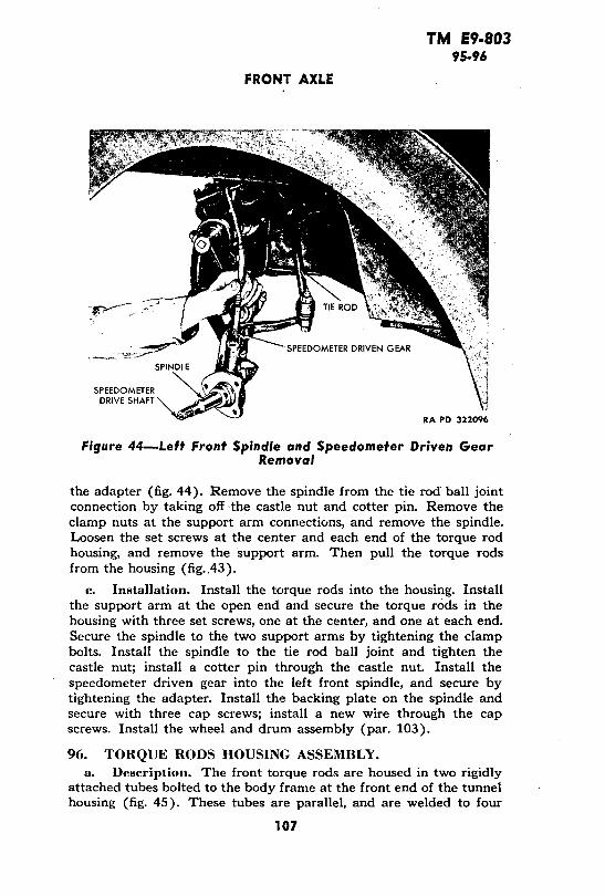
TM E9-80395-96
FRONT AXLE
_~.~?·i·~ "--SPEEDOMETER DRIVEN GEAR
SPINDLE '
SPEEDOMETERDRIVE SHAFT
RA PD 322096
Figure 44-Left Front Spindle and Speedometer Driven GearRemoval
the adapter (fig. 44). Remove the spindle from the tie rod ball jointconnection by taking off -the castle nut and cotter pin. Remove theclamp nuts at the support arm connections, and remove the spindle.Loosen the set screws at the center and each end of the torque rodhousing, and remove the support arm. Then pull the torque rodsfrom the housing (fig. 43).
c. Installation. Install the torque rods into the housing. Installthe support arm at the open end and secure the torque rods in thehousing with three set screws, one at the center, and one at each end.Secure the spindle to the two support arms by tightening the clampbolts. Install the spindle to the tie rod ball joint and tighten thecastle nut; install a cotter pin through the castle nut. Install thespeedometer driven gear into the left front spindle, and secure bytightening the adapter. Install the backing plate on the spindle andsecure with three cap screws; install a new wire through the capscrews. Install the wheel and drum assembly (par. 103).
96. TORQUE RODS HOUSING ASSEMBLY.a. Description. The front torque rods are housed in two rigidly
attached tubes bolted to the body frame at the front end of the tunnelhousing (fig. 45). These tubes are parallel, and are welded to four
107

TM E9-80396-97
GERMAN VOLKSWAGEN
SUPPORTING Me @ _
; S ~TIE RODS
SUPPORT BOLTS SUPPORT ARMS
RA PD 322138
Figure 45-Front Suspension Removed
vertical crossmembers. The two center crossmembers are calledframe heads. Lubrication fittings at each end of the housing tubespermit grease to reach the torque rods. Three socket head set screws,at the center and at the ends, anchor the torque rods within thehousing tubes. The center anchor limits the twisting action of thetorque rods to the right- and left-hand sides. The end anchors securethe torque rods to the support arms.
b. Removal. Support the front end of the body with blocks toremove the front suspension (fig. 45). Remove the four bolts at theframe heads; disconnect the steering gear assembly from the steeringcolumn by loosening the clamp bolt and nut. Roll the front suspen-sion away from the body.
c. Installation. Mount the torque rods housing assembly to thebody frame and secure with four bolts, nuts, and lock washers throughthe frame heads to the supporting mount at the front end of thetunnel housing. Connect the steering gear assembly to the steeringcolumn by tightening the clamp bolt and nut.
97. TIE ROD ASSEMBLIES.
a. Description. The right and left tie rods are fastened to thesteering Pitman arm by means of ball and socket joints. These tie
108

TM E9-80397-98
FRONT AXLE
rods transmit steering imr uulses from the teeringS gear sasembly tothe front wheels. At the front wheels, the tie rods fasten to thespindles by means of ball and socket joints.
b. Removal. Remove the ball stud nut and tap the tie rod fromthe Pitman arm or steering knuckle arm.
c. Installation. Place the tie rod in position and insert the ballstud in the Pitman arm and steering knuckle arm. Install and tightenthe ball stud nut.
OIL FITTING STEEL WASHER
FIBER WASHER WE
STEEL WASHER FIBER TORQUEWASHER ARM PIN
UPPER KING PIN-
SET SCREW
_-- *COLLAR
j --- FIBER WASHER
v v-g STEEL WASHER
SPINDLEKING PIN LOCKING BOLT
\ fl .- SPACER
WASHER
STEEL WASHER
FIBER WASHER I01E | 5|
0 9rJ~r , |TORQUE ARM PIN
FIBER WASHER
COLLAR - \ STEEL WASHER
FIBER WASHER H--EX NUT
STEEL WASHER-' LOWER KING PIN RA PD 322137
Figure 46-Left Front Spindle Disassembled
98. SPINDLE ASSEMBLIES.
a. Description. The left and right spindles are the mounts forthe front wheels and attach to the front suspension by means ofsupport arms. The spindle arms connect the left and right tie rodassemblies. The left front spindle accommodates the speedometer
109.

TM E9-80398-99
GERMAN VOLKSWAGEN
driving and driven gears and the speedometer drive shaft whichpasses horizontally through the spindle and attaches to the greasecup by means of a cotter pin (figs. 44 and 47).
b. Removal. Remove the spindles (par. 95).
c. Installation. Install the spindles (par. 95).
99. SUPPORT ARM ASSEMBLIES.
a. Description. Two support arms on each end of the torque rodhousing assembly transmit springing action to the front wheels. Thesupport arm assembly consists of an arm and sleeve arrangementwelded together at approximately right angles. The sleeve fits intothe torque rod housing over the torque rods. A set screw anchors therods within the sleeve. The arm is the lever which runs from thetorque rods to the spindle and attaches to the spindle at the verticalkingpin (fig. 43).
b. Removal. Remove the support arm assemblies (par. 95).
c. Installation. Install the support arm assemblies (par. 95).
SPEEDOMETER DRIVE SHAFT AND GEAR
RA PD 322062
Figure 47-Speedometer Drive Gear
110

TM E9-803100.101
SERVICE AND PARKING BRAKES
100. SPEEDOMETER DRIVE ASSEMBLY.
a.. Description (figs. 44 and 47). The speedometer is driven bythe left front wheel. The speedometer drive assembly consists of :a:drive shaft, driving gear, and driven gear with an adapter. The driveshaft passes horizontally through the spindle and attaches to thegrease cup by means of a cotter pin through the shaft. At the otherend of the drive shaft is the driving gear which meshes with thedriven gear within the spindle. The driven gear and shaft enterthe spindle from the top and are secured by an adapter which screwsinto the spindle vertical cylinder. A metal drive plug at the gear endof the drive shaft housing protects the gears from dirt and acts asa lubricant retainer.
b. Removal. Remove the left front wheel and drum assembly(par. 103). Remove the backing plate (par. 95). Remove thespeedometer driven gear (par. 95). Remove the spindle (par. 95)and remove the vertical kingpin from the spindle. By tapping theattaching end of the speedometer drive shaft, the drive plug can beforced out. Remove the speedometer drive shaft and gear from thesp:indle.
c. Installation. Install the speedometer drive shaft and gear intothe spindle through the horizontal cylinder. Install the drive plug intothe opening. Install the vertical kingpin on the spindle and mountthe spindle on the vehicle (par. 95). Install the speedometer drivengear (par. 95), the backing plate (par. 95), and the wheel anddrum assembly (par. 103).
Section XXIII
SERVICE AND PARKING BRAKES
101. DESCRIPTION.
a. The brakes on the Volkswagen are a mechanical, internal ex-panding type. The foot pedal application and the hand lever appli-cation each work all four brakes. The brake cables anchor to ajunction arm between the torque rods housing tubes at the front ofthe vehicle (fig. 48). When the foot brake pedal is depressed, itcauses the control pedal shaft to turn, forcing the cable junction armto move forward pulling the brake cables at the four wheels. Thehand brake lever has the same effect, but it is not attached to thecontrol pedal shaft. It is attached by means of a ratchet arrangementto the parking brake linkage rod running through the tunnel housingto the junction arm at the front (fig. 49).
111

'TM E9-803101-102
GERMAN VOLKSWAGEN
E F
A-LUBRICATOR FITTINGS E-TORQUE ROD ANCHOR BOLTB-BRAKE CABLE ANCHORS F-JUNCTION ARM RETURN SPRINGC-RETURN SPRING ANCHOR G-TORQUE RODS HOUSINGD-JUNCTION ARM H-STEERING GEAR ASSEMBLY
RA PD 322080
Figure 48-Brake Control Junction Arm
PARKING BRAKE LINKAGE ROD - FRONT BRAKE CABLE
JUNCTION As , |F EET ' | 21
,uN~ION A'~'~ - _-~CLUTCH CONTROL HAND BRAKE LEVER
ACCELERATOR SHAFT
PEDAL CONTROLBRAKE PEDAL
BRAKE PEDAL RETURN SPRING
a. ~ ~, oREAR BRAKE CABLE
CLUTCH 1PEDAL a' - CLUTCH SHAFT SUPPORT BRACKET RA PD 322058
Figure 49-Control Pedals and Brake Linkage
102. CONTROLS AND LINKAGE.
a. Description (fig. 50). The accelerator pedal is welded to asleeve which mounts on the control pedal shaft. This shaft extendsout, and to the left, at right angles from the tunnel housing. Thebrake pedal is mounted directly to the control pedal shaft. Theclutch pedal fits onto a shaft which extends through the control
112

TM E9-803102
SERVICE AND PARKING BRAKES
DIFFERENTIAL AND TRANSMISSIONFUEL UNE SUPPORT ARMS
K CABLE PRIMARY CABLE
CLUTCH CABLE CHOKE CABLE IGNITION
BRAKE CABLE THROTTLE CABLE' CABLE RA PD 322055
Figure 50-Control Cables
pedal shaft from the right-hand side. The clutch cable is attachedto a hook on this shaft. When the clutch pedal is depressed, theshaft turns, pulling the cable which passes through the tunnel andconnects. to the clutch release shaft outer lever.
b. Removal (fig. 49). Remove the protection pan at the front ofthe vehicle and disconnect the brake cables at the junction armanchor (fig. 48). Disconnect the rear brake cables at the wheelsby removing the attaching bracket. Pull the rear brake cables outthrough the rear of the tunnel housing. Remove the front brakecables by removing the attaching brackets. Using a wooden stick orany similar extension, reach into the front of the tunnel housing andlift the clutch cable off the clutch control shaft hook. Remove thepin which secures the clutch pedal to the clutch control shaft, andremove the pedal and shaft. Remove the cap screw and lock washerwhich secures the brake pedal to the control pedal shaft, and re-move the pedal. Release the brake pedal return spring. Remove theaccelerator pedal and mounting bracket by removing the cap screwsand lock washers. Remove the pin at the hand brake lever clevis,and remove the lever. Pull the brake cable junction arm out throughthe front of the tunnel housing. Pull the control pedal shaft out ofthe tunnel housing from the right-hand side. Pull the parking brakelinkage rod out through the front of the housing.
c. Installation (figs. 49 and 50). Install the control pedal shaftthrough the housing, and install the junction arm through the'front
113

TM, E9-803102-103
GERMAN VOLKSWAGEN
of the housing onto the control pedal shaft. Install the parking brakelinkage rod through the front of the housing, yoke end first, and so itfits into the groove of the.,junction arm.: Connect the hand brakelever to the linkage rod, and secure with pin and cotter pin at theclevis. Install the accelerator pedal and bracket on the control pedalshaft, and secure with cap screws and lock washers. Install the brakepedal return spring and the brake pedal onto the control shaft, andfasten the spring to the' accelerator bracket and brake pedal. Securethe pedal with a lock washer and cap screw. Install the clutch pedalshaft through the control pedal shaft from right-hand side, andinstall clutch control on the shaft. Secure the clutch pedal with astraight pin through the shaft. Using a wooden stick or any similarextension, reach into the front of the tunnel housing and maneuverthe clutch cable onto the clutch control shaft hook. Install the frontbrake cables at the junction arm and backing plate. Install the rearbrake cables into the rear of the tunnel housing (fig. 50) and secureto the junction arm. Adjust the brakes as outlined in paragraph 103 '
and install the eight cap screws which hold the protection pan atthe front of the vehicle.
BRAKEB SSHOE SECONDARY BRAKE SHOERETURNSPRING x
BRAKE SHOE RETAINER SPRING
BRAKE SHOE RETURN SPRING
RETAINER SPRING COTTER PIN
BRAKE SHOE OPERATING LEVER
OIL SEAL
PRIMARY BRAKE SHOE
BRAKE SHOE REAR :ANCHOR ASSEMBLY REAR AXLE INdES I RA PD 322070
Figure 51-Brake Assembly Installed
103. SHOE ASSEMBLIES.a. Description. The brake shoe assembly consists of the primary
brake shoe, secondary brake shoe, two return springs, shoe retainerspring, two brake shoe anchors, and the brake shoe operating lever
114

TM E9-803,103
SERVICE AND PARKING BRAKES
__,SKONDARY BRAKE SHOE
BRAKE SHOERETAINER SPRING
BRAKE SHOEOPERATING
LEVER
BRAKE SHOE RREAR ANCHORS
RETAINER SPRING BRAKE SHOECOTTER KEY RETURN SPRING
_ , i , BRAKE SHOERETURN SPRING ,'
PRIMARY BRAKE SHOE|INCHS 21 3--1 RA PD 322092
Figure 52-Brake Shoes Removed
(fig. 51). The shoes are secured to the backing plate by the rearanchor and by the retainer spring. The brake is adjusted. at theanchors and at the cable which attaches to the operating lever. Atoggle action at the lever expands the shoes against the brake drumas the cable is pulled.
b. Adjustment. A minor brake adjustment consists of tighteningthe adjusting wedge bolt (fig. 53). Turn the adjusting wedge boltin one notch at a time until the desired brake action is obtained. Ifproper adjustment of the shoes cannot be obtained by this method,it indicates that'the brake cable has stretched. Tightening the brakecable clamping nut (fig. 54) will.shorten.the cable and compensatefor slight cable stretch.
c. Removal. Remove the wheel.hub cap and lugs on the drum.Remove the wheel. Remove drum assembly. On front wheels, re-move two wheel nuts, two washers, outer bearing race, outer bearingand brake drum. On rear wheels, remove cotter pin and nut, and thenloosen drum by a sharp hammer blow on the end of the axle. NOTE:Use a piece of brass or copper to protect end of shaft. Disconnectcable attaching plate at rear of backing plate. Remove cotter pinfrom the retainer spring and remove the two return springs fromthe shoes. Lift off the shoes, anchor pins, and operating lever (fig. 52).
115

TM ,E9-803103
GERMAN VOLKSWAGEN
A~~~~~~~~~~~~:P _NUT
RA PD 322054
Figure 53-Adjusting Brake Shoes
SH.OC /
ABSORBER
SUPPORT ARM
RA PD 322118
Figure 54-Adjusting Brake Cable
116

TM E9-803103-105
STEERING SYSTEM
d. Installation. Install the anchor pins into the backing plateboss, and place the brake shoes in the grooves on the pins. Installrear return spring. Install the brake operating lever. Connect thebrake cable to the brake shoe operating lever, and place the shoes intothe grooves of the lever. Install front return spring. Install shoeretainer spring and secure with cotter pin (fig. 51). Install brakedrum assembly on front wheel, after bearings have been coated withgrease, replace inner bearing, brake drum, outer bearing, race, flatwasher and nut. Pull nut up until tight and back off 1/4 turn, thencheck nut with lock washer and nut. Lock tightly without changingposition of inside nut. Replace grease cap. On rear wheel, replacebrake drum and secure tightly with nut and cotter pin. Install wheel.Adjust the brakes (step b above).
Section XXIV
STEERING SYSTEM
104. DESCRIPTION.
a. The steering gear is the worm and sector type, and differsfrom the conventional construction in that the steering worm shaftis short, and an extension is used to connect the worm shaft to thesteering wheel. The sector shaft is fitted with a socket into whichthe sector bearing is located. The sector bearing is designed to meshwith the threads of the worm shaft. The sector shaft extends throughthe steering gear housing, and the steering Pitman arm attaches tothe lower end of the sector shaft. The opposite end of the Pitmanarm is designed to accommodate two ball studs which are located inthe inner ends of the tie rods. The tie rod bakl studs are attached tothe Pitman arm, and the tie rods extend to the steering knucklearms. Ball studs in the outer ends of the tie rods are attached to thesteering knuckle arms.
105. STEERING PITMAN ARM.
a. Description. The steering Pitman arm is located beneaththe steering gear assembly, and fastens to the sector shaft by a clampbolt, nut, and lock washer. The ball end of the steering Pitman armprovides for two ball and socket joints to which are attached theleft and right tie rods. The conventional drag link is not used on thisvehicle.
b. Removal. Remove the protection pan from the front of thevehicle by removing the eight cap screws which hold it in place.Remove the clamp bolt, nut, and lock washer at the b se of the
117.

TM E9-803105-106
GERMAN VOLKSWAGEN
sector shaft, and slide the Pitman arm from the sector shaft Removethe two ball and socket joints from the other end of the steeringPitman arm.
SECTOR SHAFT
ADJUSTINGSLEEVE
LOCK NU,
FILLER PLUG / 1 LOCK NUT
CLAMP SCREW
RA PD 322119
Figure 55-Adjusting Steering Gear
c. Installation. Install the steering Pitman arm to the sectorshaft and secure with a clamp bolt, lock washer, and nut. Install twoball and socket joints on the other end of the arm, and install theleft and right tie rods to the joints. Install the protection pan on thefront of the vehicle, and install and tighten the eight cap screws.
106. STEERING GEAR ASSEMBLY.a. Description. The steering gear assembly is mounted to the
upper torque rod housing at the front left center of the vehicle(fig. 45).
b. Adjustment. There are two adjustments provided for thesteering, one to eliminate backlash between the steering gear worm
118

TM E9-803106
STEERING SYSTEM
STEERING GEAR BEARING
ADJUSTING SLEEVE CAP SCREW
STEERING GEAR WORM - Dm
CAP SCREW LOCK WASHER
LOCK WASHER SECTOR HEX NUT---@q t
sten gr wesECTOR PIN a eni i_ l~1 GEAR HOUSING
,u/ Ad SECTOR SHAFTFILLERPLUG SECTOR SPRING
SECTOR COVER
LOCK NUT SECTOR ADJUSTING SCREW RA PD 322081
Figure 56-Steering Gear Disassembled
and its bearing, and the other to eliminate backlash between thesteering gear worm and the sector. To eliminate backlash betweenthe steering gear worm and bearings, turn the front wheels to thestraight ahead position. Loosen the clamp screw at the top of thesteering gear housing, and tighten the adjusting sleeve (fig. 56).Tighten the sleeve only enough to eliminate up-and-down motionof the steering gear worm, and tighten the housing clamp screw. Toeliminate backlash between the steering gear worm and sector, turnthe front wheels to the straight ahead position. Loosen the sectoradjusting screw lock nut (fig. 56) and tighten the sector adjustingscrew until no backlash exists between the sector and the steeringgear worm. Tighten the adjusting screw lock nut.
c. Removal. Remove the protection pan on the front of thevehicle. Remove the steering Pitman arm (par. 105). Remove theclamp bolt and nut at the steering column connection, and separatethe steering column from the steering gear assembly. Remove nutsand lock washers from mounting studs on the torque rod housingbracket, and remove the steering gear assembly.
119

'TM E9-803106-107
GERMAN VOLKSWAGEN
d. * Installation. Install the steering gear assembly on the torquerod housing bracket, and secure lock washers and nuts to the mount-ing studs. Connect the steering column to the steering gear assembly,and tighten the clamp bolt, lock washer, and nut. Install the Pitmanarm to the sector shaft (par. 105).
HORN BUTTON ,
SPRING
STEERING WHEEL RA PD 322074
Figure 57--Steering Wheel Removed
107. STEERING WHEEL ASSEMBLY.
a. Description. The steering wheel is the standard type com-monly used in American vehicles. The steering wheel assembly con-sists of the horn button retainer, horn button, spring, retainer nut,wheel, and horn button contact.
b. Removal. Pry the horn button retainer from the hub of thewheel. Lift out the horn button and spring, and remove the steeringwheel retainer nut. The wheel is splined to the steering column tube,and care should be taken in order to keep from damaging the splineswhen it is lifted off (fig. 57). Pull the steering wheel from the steeringtube.
c. Installation. Install the steering wheel on the splined steeringtube, allowing the horn button contact wire to fit through the wheelhub. Tighten the retainer nut to draw the wheel onto the tube, andinstall the spring and horn button. Secure the button with the tight-fitting retainer which presses into position over the button.
120

TM 'E9-803108-109
Section XXV
TIRES, TUBES, AND WHEELS
108. DESCRIPTION.
a. The Volkswagen is equipped with five steel disk wheels withdeep set rims, and low-pressure synthetic tires and tubes, size 5.25-16.Air pressure should be approximately 20 pounds in front tires and26 pounds in the rear tires.
109. TIRES, TUBES, AND WHEELS.
a. Removal. Jack up the vehicle and pry the hub cap from thewheel. Remove lug nuts and pull wheel and tire from drum. Removevalve core from valve stem to deflate tire thoroughly. Pry the tirefrom the rim, and pull the inner tube out of the tire.
b. Installation. Install tube in tire. Install tire and tube onwheel rim, using care to avoid pinching the tube. Inflate tire toproper pressure and install wheel on the drum, and secure with lugnuts; tighten the nuts gradually and alternate from side to side toensure a proper fit. Lower vehicle to ground and withdraw the jack.
TUBE TIRE
WHEEL
RA PD 322056
Figure 58-Wheel, Tire, and Tube
121

TM' E9-803109-110
GERMAN VOLKSWAGEN
SPEEDOMETER CABLE
LOCK WASHEREL NUTS
Figure 59-Left Front Brake Drum and Wheel BearingDisassembled
SPEEDOMETER DRIVE SHAFT
OUTER BEARING GREASE
FLAT WASHER CAP
LOCK WASHER
RA PD 322088
Figure 59-Left Front Brake Drum and Wheel BearingDisassembled
110. ADJUSTMENT.
a. No provision is made for adjusting the caster or camber anglesof the front wheels of the Volkswagen.
b. Toe-in can be adjusted as follows: Place the front wheels in
a straight ahead position; measure the distance between the rear ofthe front wheels and the front of the front wheels, being sure thatthese measurements are taken at the same height from the groundin each case. If the distance between the front of the front wheels is
TOE-IN GAGE
Figure 60-Front Wheel Toe-in Adjustment
122

TM E9.803110-112
SHOCK ABSORBERS
N0 to l/s inch less than the distance between the rear of the frontwheels, toe-in is correct. If this measurement is not obtained, loosenthe tie rod yoke clamp bolt at each end of each tie rod. Turn eachtie rod until each wheel points exactly straight ahead. Turn eachtie rod enough to make each wheel toe-in A 6 inch; this will give acombined toe-in of 1/8 inch, which is satisfactory.
Section XXVI
SHOCK ABSORBERS
111. DESCRIPTION.
a. The Volkswagen is equipped with single-acting, hydraulicshock absorbers on the front suspension, and double-acting, hydraulicshock absorbers on the rear suspension. The base of the front shockabsorber is bolted to the torque rdd housing support and the topto the. upper support arm (fig. 61). The rear shock absorber ismounted to a bracket behind the rear torque rod housing, and tothe rear torque arm bracket on the drive shaft housing.
SUPPORT ARM BRAKE CABLE
SUPPORT ARM
RA PD 322133
Figure 61-Front Shock Absorber Installed
112. FRONT SHOCK ABSORBERS.
a. Description. The front shock absorbers are single-acting,airplane-type; they cushion the return spring action of the fronttorque rods.
123

TM' E9-803112-113
GERMAN VOLKSWAGEN
b. Removal (fig. 61). Remove cotter pin and castle nut at thebase mount of the front shock absorber. Remove the cap screw andflat washer which secure the absorber to the top support arm. Re-move the shock absorber from the mounts.
c. Installation. Install the front shock absorber to the uppersupport arm and to the torque rods housing support. Be careful notto damage the rubber bushings. Install flat washer and cap screw attop mount, and castle nut and cotter pin at base mount.
FLUID FILLER SCREW MOUNTING STUD
RA PD 322071
Figure 62-Removing Rear Shock Absorber
113. REAR SHOCK ABSORBERS.
a. Description. The rear shock absorbers are the double-acting,hydraulic-type; they are mounted to a bracket directly behind therear torque rod housing and to the rear torque arm bracket on thedrive shaft housing. The fluid level can be checked at the filler open-ing, and should be maintained at the top of the opening.
b. Removal (fig. 62). Disconnect the link at the drive shafthousing. Remove the hex nut, cap screw and lock washers from thebracket mount behind the rear torque rod housing. Remove the nutand flat washer from the rear torque arm bracket on the drive shafthousing, and remove the shock absorber.
c. Installation (fig. 62). Install the rear shock absorber to thestud on the mounting bracket, and. secure with a lock washer andnut. Install a lock washer and cap screw to attach the shock absorberto the torque rod housing. Connect the shock absorber link to thedrive shaft housing.
124

TM E9-803114-116
BODY AND FRAME
Section XXVII
INSTRUMENT PANEL AND INSTRUMENTS114. DESCRIPTION.
a. The indicating instruments are carried in an instrumentpanel immediately below the windshield. The instruments indicatethe condition of the various components of the vehicle while it isin motion.
115. REPLACEMENT.
a. Instrument Panel. The instrument panel is attached to thebody by a single bolt at each end of the panel. Remove these boltsand disconnect instrument wires and cables from the instruments,and remove the panel. When installing a new panel, first connect theinstrument wires and cables to the corresponding instruments. Placethe panel in position and install the bolt, nut, and lock washer whichsecure each end of the panel to the body..
b. Instruments. Disconnect instrument wires or cables fromthe instrument to be replaced. Remove the nuts and lock washersfrom the studs which hold the instrument to the panel, and removethe instrument. When installing a new instrument, see that it issecurely attached to the instrument panel before connecting thewires or cables.
Section XXVIIIBODY AND FRAME
116. DESCRIPTION.a. The base stamping comprising the floor of the vehicle is
ribbed. The sheet steel center housing is tunnel-shaped and has apiece of sheet metal welded to the under side. It forks in the rearin order to form a mount for transmission and differential. In thefront, the center tunnel broadens out and supports the front suspen-sion assembly. This center tunnel houses the throttle, clutch, chokecables, the two rear brake cables, the parking brake linkage rod, thebrake cable junction arm, the transmission shift rod and the fuel line.
b. The all steel body has a space for equipment above the frontand rear suspensions. The doors are hinge-bolted to the center postsand the fenders are welded to the body. The windshield is made ofsafety glass and can be lowered and secured in a horizontal position.Detachable curtains are provided for inclement weather conditions.The adjustable front seats are firmly bracketed to the undercarriage.The rear seat cushion is set into the carriage and the back of theseat opens into the accessory box.
125

TM' E9-803116-122
GERMAN VOLKSWAGEN
c. A box for holding papers and a hand lamp is found in fronton the left-hand side. Combat equipment for the crew is sometimesplaced under the front seats and sometimes under the right-handside of the rear seat. A spade is held in brackets on the right sideof the front cowl.
117. BATTERY BOX.
a. The battery box is secured to the floor under the left rearseat by cap screws and lock washers. It is necessary to lift out theseat cushion to reach the battery box. Disconnect battery cables andlift out battery. Remove cap screws and lock washers from the flangesand lift out battery box. Install the battery box by securing capscrews and lock washers; install battery into box and attach cables,and install rear seat cushion.
118. WINDSHIELD WIPER BLADE.
a. When a new blade is necessary, install it on the end of thewindshield wiper arm at the hook connection.
119. SEAT CUSHIONS.a. The seat cushions are a loose fit and can be removed and in-
stalled freely.
120. DOORS.
a. The doors on each side of the vehicle fasten to the centerposts by two hinge bolts in a common hinge. They can be removedeasily by driving out the bolts. Install by placing in position on thehinges and tapping bolt into place from the top of the hinge.
121. FLOOR GRATING.
a. The wooden floor grating is a loose fit. It is held in place bythe front seat brackets. Remove the cap screws and lock washersfrom front seat brackets and lift out seats. Remove floor grating fromvehicle. To install, fit floor grating into position and install frontseats and brackets and secure with cap screws and lock washers.
122. TOWING HOOKS.
a. Two hooks are mounted to the body front and rear for towingpurposes (figs. 1 and 2). Remove the bolts, nuts, and lock washersat the hook connection under the front cowl and under the bodycrossmember at the extreme rear of vehicle, and remove towing hooks.Install by placing in the slots provided and secure with bolts, nuts,and lock washers.
126

TM E9-803123-125
BODY AND FRAME
123. SEAT ASSEMBLIES.
a. The front seats are bracketed to the metal floor stamping overthe wooden floor grating, Remove the cap screws and lock washersfrom brackets and lift out front seat assemblies. Install by placing inposition and securing brackets at the base with lock washers and capscrews.
b. The rear seat back folds forward to allow access to the equip-ment space. The cushion is a loose fit and simply rests in place onwelded flanges.
124. TOP AND SIDE CURTAINS.
a. The body top is the conventional canvas, fold-back type whichcan be secured at windshield top by clamp nuts when in use; two cellu-loid windows are provided at the rear.
b. Canvas curtains with celluloid windows are provided for in-clement weather. They are the conventional, snap-on type. Whennot in use, they can be stowed behind the rear seat.
125. WINDSHIELD ASSEMBLY.
a. The windshield is a single section of shatterproof glass clampedinto a frame flush with the body frame structure. It can fold forwardand clamp to the cowl. Remove the windshield wiper connections,
.take out attaching screws, and remove windshield assembly. Installthe windshield assembly by mounting flush with frame at the cowland secure with attaching screws. Install the windshield wiper con-nections.
127

TM 09-803126-127'
GERMAN VOLKSWAGEN
APPENDIX
Section XXIX
SHIPMENT AND TEMPORARY STORAGE
126. GENERAL INSTRUCTIONS.
a. Preparation for domestic shipment of the vehicle is the sameas preparation for temporary storage or bivouac. Preparation forshipment by rail includes instructions for loading and unloading thevehicle, blocking necessary to secure the vehicle on freight cars,number of vehicles per freight car, clearance, weight, and other in-formation necessary to properly prepare the vehicle for rail ship-ment. For more detailed information, and for preparation for in-definite storage refer to AR 850-18.
127. PREPARATION FOR TEMPORARY STORAGE ORDOMESTIC SHIPMENT.
a. Vehicles to be prepared for temporary storage or domesticshipment are those ready for immediate service but not used forless than 30 days. If vehicles are to be indefinitely stored after ship-ment by rail, they will be prepared for such storage at their destina-tion.
b. If the vehicles are to be temporarily stored or bivouacked,take the following precautions:
(1) LUBRICATION. Lubricate the vehicle completely (par. 19).(2) BATTERY. Check battery and terminals for corrosion and,
if necessary, clean and thoroughly service battery (par. 82).(3) TIRES. Clean, inspect, and properly inflate all tires. Replace
with serviceable tires (if available), all tires requiring retreading orrepairing. Do not store vehicles on floors, cinders, or other surfaceswhich are soaked with oil or grease. Wash off imlr rdiately any oil,grease, gasoline, or kerosene which comes in contact with the tiresunder any circumstances.
(4) ROAD TEST. The preparation for limited storage will includea road test of at least 5 miles (8 kilometers), after the battery, lubri-cation, and tire service, to check on general condition of the vehicle.Correct any defects noted in the vehicle operation, before the vehicleis stored, or note on a tag attached to the steering wheel, stating therepairs needed or describing the condition present. A written reportof these items will then be made to the officer in charge.
(5) FUEL IN TANKS. It is not necessary to remove the fuel fromthe tanks for shipment within the United States, nor to label the tanks
128

TM E9-803·127-128
SHIPMENT AND TEMPORARY STORAGE
under Interstate Commerce Commission Regulations. Leave fuel inthe tanks except when storing in locations where fire ordinances orother local regulations require removal of all gasoline before storage.
(6) EXTERIOR OF VEHICLES. Remove rust appearing on any partof the vehicle with flint paper. Repaint painted surfaces whenevernecessary to protect wood, or metal. Coat exposed polished metalsurfaces susceptible to rust with medium grade preservative lubri-cating oil. Make sure the doors are firmly closed, the top raised, allcurtains in place, and the windshield closed. Leave rubber floor mats(if provided) flat on the floor. Tools, tire chains, and fire extinguishersmay remain in place in the vehicle.
(7) INSPECTION. Make a systematic inspection just before ship-ment or temporary storage to insure all above steps have been covered,and that the vehicle is ready for operation on call. Make a list of allmissing or damaged items, and attach it to the steering wheel. Referto "Before-operation Service" (par. 21).
(8) ENGINE. To prepare the engine for storage, remove the aircleaner from the carburetor. Start the engine, and set the throttle torun the engine at a fast idle. Pour 1 pint of medium grade preserva-tive lubricating oil, Ordnance Department Specification AXS-674 ofthe latest issue in effect, into the carburetor throat, being careful notto choke the engine. Turn off the ignition switch as quickly as possibleafter the oil has been poured into, the carburetor. With the engineswitch off, open the throttle wide, and turn the engine five completerevolutions by means of the cranking motor. If the engine cannot beturned by the cranking motor with the switch off, turn it by hand,or disconnect the high tension lead and ground it before turning theengine by means of the cranking motor. Then reinstall the air cleaner.
(9) BRAKES. Release brakes and chock the wheels.
c. Inspections in Limited Storage. Vehicles in limited storagewill be inspected weekly for conditions of tires and battery. If wateris added to the battery when freezing weather is anticipated, rechargeit with a portable charger, or remove it for charging. Do not attemptto charge the battery by running the engine.
128. LOADING AND BLOCKING FOR RAIL SHIPMENT.
a. Preparation. In addition to the preparation described inparagraph 127, when ordnance vehicles are prepared for domesticshipment, the following preparations and precautions will be taken:
(1) EXTERIOR. Cover the body of the vehicle with a canvascover.
(2) TIRES. Inflate tires from 5 to 10 pounds above normal pres-sure.
129

TM E9-803128
GERMAN VOLKSWAGEN
(3) BATTERY. Disconnect the battery to prevent its discharge byvandalism or accident. This may be accomplished by disconnectingthe positive lead, taping the end of the lead, and tying it back awayfrom the battery.
(4) BRAKES. The brakes must be applied and the transmissionplaced in low gear after the vehicle has been placed in position, witha brake wheel clearance of at feast 6 inches (A, fig. 63). Locatethe vehicles on the car in such a manner as to prevent the car fromcarrying an unbalanced load.
(5) All cars containing ordnance vehicles must be placarded"DO NOT HUMP."
(6) Ordnance vehicles may be shipped on flat cars, end-doorbox cars, side-door box cars, or drop-end gondola cars, or whichevertype is the most convenient.
b. Facilities for Loading. Whenever possible, load and unloadvehicles from open cars under their own power, using permanent endramps and spanning platforms. Movement from one flat car to an-other along the length of the train is made possible by cross-overplates or spanning platforms. If no permanent end ramp is available,an improvised ramp can be made from railroad ties. Vehicles maybe loaded in gondola cars without drop ends by using a crane. In caseof shipment in side-door cars, using a dolly-type jack to warp thevehicles into position within the car.
c. Securing Vehicles. In securing or blocking a vehicle, threemotions, lengthwise, sidewise, and bouncing, must be prevented. Thereare two approved methods of blocking the vehicles on freight cars,as described below.
(1) METHOD 1 (fig. 63). Locate eight blocks "B," one to the frontand one to the rear of each wheel. Nail the heel of each block tothe car floor, using five 40-penny nails to each block. Toenail thatportion of the block under the tread to the car floor with two 40-pennynails to each block. Locate two blocks "D" against the outside faceof each wheel. Nail the lower block to the car floor with three 40-penny nails, and the top block to the lower block with three 40-pennynails. Pass four strands, two wrappings, of No. 8 gage, black annealedwire "C," through the towing hook at the front of the vehicle, andthen through a stake pocket on the railroad car. Perform the sameoperation at the rear of the vehicle. Duplicate these two operationson the opposite side of the vehicle. Tighten the wires enough to re-move slack. When a box car is used, this strapping must be appliedin a similar fashion, and attached to the floor by the use of blockingor anchor plates. This strapping is not required when gondola carsare used.
130

I If'l i;-ouJ128
SHIPMENT AND TEMPORARY STORAGE
C a D B B C
or . 1 1I fitC F G H G F F G H G F C
6. X1 2 -'
6 L8"CK-- 4C ." CHAMFER ATBLCK2BLOCK-D 2" CHAMFER AT
B'q'%LOCK--F . : LENGr. TO sur .BLOCK-G RA PD 336917
Figure 63-Blocking Requirements for Securing Vehicles onRailroad Cars
131

'1I M tY-803128
GERMAN VOLKSWAGEN
(2) METHOD 2 (fig. 63). Place four blocks "G", one to the frontand one to the rear of each set of wheels. These blocks are to be atleast 8 inches wider than the over-all width of the vehicle at the carfloor. Using sixteen blocks "F", locate two against blocks "G" to thefront of each wheel, and two against blocks "G" to the rear of eachwheel. Nail the lower cleat to the floor with three 40-penny nails, andthe top cleat to the cleat below with three 40-penny nails. Locatefour cleats "H" on the outside of each wheel to the top of each block"G" with two 40-penny nails. Pass four strands, two wrappings, ofNo. 8 gage, black annealed wire "C", through tow hooks, front andrear, and through stake pockets on railroad car as described inMethod 1 above.
,d. Shipping Data. Metric U. 5.
Length, over-all ........................................ 3,740 mm 7 ft 101/2 in.Width, over-all ........................................ 1,600 mm 5 ft 5 in.Height, top down ...................................... 1,111 mm 3 ft 8 in.Shipping weight ........................................ 725 kg 1,598 lbApproximate floor area ................................ 6 sq m 43 sq ftApproximate volunie .................................... 7 cu m 157 cu ftBearing pressure (lb per sq ft of floor area) .................................... 37Bearing pressure (kg per sq m of floor area) .................................. 17
132

TM E9-803129-131
Section XXX
REFERENCES
129. PUBLICATIONS INDEXES.
a. The following publications indexes should be consulted fre-quently for latest changes to, or revisions of, the publications givenin this list of references and for new publications relating to materielcovered in this manual:
Introduction to Ordnance Catalog (explainsSNL system) ........................................ ... ASF Cat.
ORD-1 IOCOrdnance publications for supply index (in-
dex to SNL's) ........................................... ASF Cat.ORD-2 OPSI
Index to ordnance publications (lists FM's,TM's, TC's and TB's of interest to Ordnancepersonnel, MWO's, OPSR's, BSD, S of SR's,OSSC's and OFSB's. Includes alphabeticallisting of Ordnance major items with publi-cations pertaining thereto) .......................... OFSB 1-1
List of publications for training (lists MR's,MTP's, T/BA's, T/A's, and FM's, TM's andTR's concerning training) ............................ FM 21-6
List of training films, film strips and film bul-letins (lists TF's, FS's, and FB's by serialnumber and subject) .................................... FM 21-7
Military training aids (lists graphic trainingaids, models, devices, and displays) ............ FM 21-8
130. STANDARD NOMENCLATURE LISTS.
Cleaning, preserving and lubrication materials,recoil fluids, special oils, and miscellaneousrelated items ..................................... ... SNL K-1
Soldering, brazing and welding materials,gases and related items ................................ SNL K-2
Tool-sets, motor transport ................................ SNL N-19
131. EXPLANATORY PUBLICATIONS.
a. Fundamental Principles.
Automotive brakes ..................................... TM 10-565Automotive electricity .................................... TM 10-580Automotive lubrication .................................... TM 10-540Automotive power transmission units ............ TM 10-585Basic maintenance manual ............................ TM 38-250
133

TM E9,-803131
GERMAN VOLKSWAGEN
Chassis, body, and trailer units ........................ TM 10-560Driver's manual ........................................ TM 10-460Driver selection and training ............................ TM 21-300Electrical fundamentals .................................. TM 1-455Fuels and carburetion ...................................... TM 10-550Military motor vehicles .................................... AR 850-15Motor vehicle inspections and preventive
maintenance service .................................... TM 9-2810Precautions in handling gasoline .................... AR 850-20Standard military motor vehicles .................... TM 9-2800The internal combustion engine ......... : .............. TM 10-570
b. Maintenance and Repair.Cleaning, preserving, lubricating, and welding
materials, and similar items issued by theOrdnance Department ................................ TM 9-850
Cold weather lubrication and service of com-bat vehicles and automotive materiel ........ OFSB 6-11
Maintenance and care of pneumatic tires andrubber treads ...................................... .. TM 31-200
c. Protection of Materiel.Camouflage ........................................ FM 5-20Chemical decontamination, materials and
equipment ...................................... TM 3-220Decontamination of armored force vehicles...... FM 17-59Defense against chemical attack ...................... FM 21-40Explosives and demolitions ............................. FM 5-25Military chemistry and chemical agents .......... TM 3-215
d. Storage and Shipment.Registration of motor vehicles ........................ AR 850-10Rules governing the loading of mechanized
and motorized army equipment, also majorcaliber guns, for the United States Armyand Navy, on open top equipment publishedby Operations and Maintenance Depart-ment of Association of American Railroads.
Storage of motor vehicle equipment ................ AR 850-18Ordnance field service storage and shipment
chart-group G major items ........................ OSSC-6
134

TM E9.803
INDEX
A Page Page
Accelerator ................ 10 Blocking for rail shipment ....... 129
Accessories Body and frame .. ......... 125after-operation service ......... 30 Brake drums
at-halt service ............... 29 at-halt service ................ 28before-operation services ....... 25 ' road test ................... 37
description .......... ........ 6 Brake shoe. assemblies
road test .................... 37 adjustment and removal....... 115
Accidents, reports of ............ 1, 27 .description ................ 114
Air cleaners installation ................. 117
after-operation and weekly road test ................... 42, 43
.services ................ 31 Brakes
at-halt service ............... 29 descriptiondescription ....... ......... 84 brakes ................. 11, 111lubrication .................. 22 braking system ............. 5
removal and installation ....... 85 controls and linkage ........ 112
road test .................... 40 pedal .............. .... 10Ammeter ' during-operation service...... 27
before-operation service ........ 26 rail shipment ............... 130description .................. 11 removal and installation ofduring-operation service ....... 28 controls and linkage .... 113inoperative ammeter .......... 60 road test ............ 36, 41, 42, 44road test ................... 36 shipment and storage ....... 127
Axles trouble shooting
at-halt service ................ 28 parking brake system ...... 58description service brake system...... 56
front axle ................. 106 Breather caps, after-operation and
rear axle ................ 103 weekly services .......... 31road test ................... 44
trouble shooting .............. 56 C
B Camshaft data................. 63
Batteries Capacities, fuel and oil .......... 6
after-operation and weekly Carburetorservices ................ 30 air leaks .................... 49
cold-weather operation........ 16 description and adjustment ..... 83
description, removal, and instal- engine tune-up ........ 64lation .................. 94 removal and installation ....... 83
engine tune-up ............... 64 road test ..................... 40
hot-weather operation ......... 17 Chassis, cold-weather operation.. 17
low battery .................. 52 Chokeoverheated battery ............ 53 before-operation service ....... 25
rail shipment ................ 130 description .................. 10road test .................... 38 road test ..................... 40
servicing ................... 94 Circuit breakers, road test ....... 46storage and shipment .......... 128 Cleaning .................... 22, 32trouble shooting ............. 53 Clutch
Battery box.' ................. 126 adjustment of control linkage ... 74Blackout.lights (See Lights) data ....................... 73
135

TM E9-803
GERMAN VOLKSWAGEN
C-(contd.) Page D PageClutch- (contd.) Decontaminator
:description after-operation service......... 30clutch .................... 72 before-operation service ..... 26controls and linkage ......... 74 road test .................... 47
during-operation service ....... 27 Desert operation ................ 18removal and installation of con- Differential
trols and linkage ........ 75 description ................. 5, 100road test .................. 36, 44 installation .:. ........... 102trouble shooting ............ 50 lubrication ................ 15, 22
Clutch driven plate ............. 75 removal ...... 101Clutch pedal ............ ...... i road test............... 44
DistributorClutch pilot bushing ............. 73operation10
cold-weather operation....... 10Clutch release bearing ........... . ..... .74 description, removal, and instal-Coil, ignition lation .................. 89
cold-weather operation ........ 16 engine tune-up64description and removal ..... 88 faty points.52installation .................. 89 lubrication ............. 23road test....................road test ................... 39
Cold-weather operation .......... 13 Doors ........... .......... 126
Condenser, distributor.......... 90 Drive belt, road test ........... 39Drive shaft housing assembly.... 105
- Controls Driver's accident report, motordescription .................. 9transportationduring-operation service .... ....... 27 Driver's trip ticket and preventive
Conversion table (metric system) 6 maintenance service record 1, 24
Cooling system Driving the vehicle: ........... 12, 18description .................. 87 Drums and supports, road test..41, 43trouble shooting .............. 51 Dusty conditions of operation ..... 17
Duty roster .................. '.. 2Crankcase
keeping oil fluid .............. 14 Elubrication .................. 22road test.' ................. 38 Electrical system
cold-weather operation ........ 16Cranking motor (See also Wiring)
cold-weather operation ........ 16 Enginedescription cleaning .................... 32
cranking motor. ........... 92 data ....................... 62cranking motor button ...... 9 description ............... 2,60,69
inoperative motor ........... 53 during-operation service ....... 27jammed motor ................ 48 installation ................. 71lubrication- ................. 23 operation checks .......... 27, 30road test ................... 41 overheated engine............ 51(See also Solenoid, cranking removal ................... 69
motor) road test ............... 37, 41, 44
Crankshaft data ................ 63 shipment and storage .......... 129starting the engine............ 12
Curtains ..................... 127 stopping the engine........... 13
Cylinder head, road test ....... 38 tune-up ..................... 64
136

TM E9-803
INDEX
E--(contd.) Page Page
Engine-( contd.) Fuel system
trouble shooting .............. 48 cold-weather operation........ 1625 inoperative system ............ 48
warm-up ....................warm-up ........ trouble shooting .............. 50(See also Lubrication system, trouble shooting50
Fuel tankedescription, removal, and instal-
Exhaust pipes, road test .......... 45ation.85
Exhaust system shipment and storage .......... 128
description .................. 81 Fuse blocks, road test.......... 46
trouble shooting ........... , 51 Fuse boxes ............. ....... 9,99
Fuses, spare ................... 47
FG
Fan 87 Gages, road test ............... 35
descrp ti .................. ..Gasoline ...................... 14
road test. s t Gasoi4 39Gear oil levels
Fenders after-operation service......... 31after-operation service ......... road test3237
at-halt service ........... .... 29 Gearshift lever ................. 10
before-operation service....... 26Generating system
road test ................... .46d sr i 92description ........... 9.2..... 92
Final reduction assembly trouble shooting........... 52
description and removal ...... 103 Generator
installation ................. 104 cold-weather operation ....... 16
Fire extinguisher description .................. 94
after-operation service ......... 30 installation ................. 72
before-operation service ....... 25 lubrication .................. 23
road test ...... .............. 47 removal .................... 71
First-aid kit ................... 47 trouble shooting ............. 52,53
Generator regulator ........... 93Frame
road test . .... ...... 45 Grating, floor.......... 126
(See also Body and frame)
Fuel
after-operation service......... 30 Headlights (See Lights)
at-halt service . ......... 28 Horn
before-operation service ....... 25 after-operation service......... 30
Fuel cock..............'....... 10 before-operation service ....... 26
Fuel filters description
after-operation and weekly ser- horn ..................... 97
vices ................... 31 horn button ................ 9
clogged filter ................. 50 installation ........ ......... 99
road test .............. .... 40' maintenance, and removal...... 97
Fuel lines ..................... 86 road test ...... . ............ 36
Fuel pump Hot-weather operation.......... 17
description ........... ....... 84 Hubs
inoperative pump ............. 50 at-halt service ................ 28
removal and installation ....... 84 road test ..... :.............. 37
road test .................... 40 trouble shooting .............. 58
137

TM E9.803
GERMAN VOLKSWAGEN
I Page Page
Ignition Lubrication ............ 15, 19, 32, 45
description Lubrication system, engine ....... 76
ignition switch ............. 9
ignition system ............. 88 Mengine tune-up ............... 64 Maintenance, preventive
faulty coil or condenser ........ 52 after-operation and weekly..... 29
inoperative system ............ 48 at-halt ..................... 28
preignition .................. 49 before-operation ............. 25
timing ..................... 65 during-operation ............. 27
trouble shooting .............. 51 first echelon ................. 23
Instrument panel, description and second echelon ............... 32
replacement ............. 125 Maintenance reports ............. 1, 2
Instruments Manifolds
after-operation service ......... 30 aif leaks .................... 49
before-operation service....... 25 description and removal
description ................ 11, 125 exhaust manifolds .......... 68
during-operation service ....... 28 intake manifolds ........... 67
replacement ................. 125 installation ................. 68
road test .................... 35 leaking gaskets ............... 51
trouble shooting ............. 60 road test .................... 40
Intake and exhaust systems Mirrors
description' .................. 81 after-operation service ......... 30
trouble shooting .............. 51 at-halt service ................ 29
before-operation service ....... 26
L road test ................. 36,46
Lamps Misfires, engine ................ 49
after-operation service ......... 30 Mud, operation in .............. 18
before-operation service ........ 26 Muffler
description (trouble lamp socket) 9 defective muffler ............. 51
failure to light ............... 55 description ................. 86
road test ................. ... 46 roadtest ................... 45
(See also Lights)
Leaks
after-operation service ......... 31 Oil
at-halt service ................ 29 after-operation service ......... 30
before-operation service ....... 25 at-halt service ................ 28
road test ................... 37,41 before-operation service ........ 25
Lights Oil bath air cleaner (See Air cleaner)
cold-weather operation ........ 16 Oil consumption, excessive ....... 49
description Oil cooler
indicators ................. 11 description and removal ........ 78
lights ................ 95, 96, 97 installation ................. 79
switches ................. 9, 10 road test .................... 39
installation .............. 95, 96, 97 Oil pressure gagesmaintenance and adjustment .. 95, 97 description .................. 11
removal ................ 95, 96, 97 failure to register ............ 60
trouble shooting ............. 53 Oil pressure indicator
(See also Lamps) before-operation service ....... 26
Loading for rail shipment ........ 129 during-operation service ....... 28
138

TM E9-803
INDEX
O-(contd.) Page Page
Oil pressure indicator-(contd.) Solenoid, cranking motorroad test .............. ...... 35 description and removal ....... 92
Oil pump .................. .. installation ................. 93
Oil seal, removal and installation.. 80 Spark plugsOil strainer assembly cold-weather operation ........ 16
description and removal ....... 77 engine tune-up ............. 64installation ................. 78 faulty plugs ................ 51
Oilcan points ........................... 2391removal .90
p Specifications, vehicle........... 5Speedometer
Paint and markings ............. 46 description11Parts, replacement .............. 7 description ................... 11
during-operation service ....... 28Pitman arm, steering ............ 117
road test ........... ......... 36Pumps (See Oil pump and Fuel pump) trouble shooting60
trouble shooting .............. 60
R Speedometer drive assembly. 111Spindle assemblies (front axle) ... 109
Rail shipment .............. -.. 129 Starting systemReduction gear housings, description .................. 91
lubrication ............... 15 trouble shooting .............. 52Reports and records ............. 1, 23 Starting the engine ............ 12'Road test ..................... 35 Steep-grade driving ............. 18Road test preparatory to limited Steering gear
storage ............. 1..... 128 adjustment of assembly ........ 118Rocker arms after-operation service ........ 31
description and removal ....... 66 at-halt service ............... 28installation ................. 67 before-operation service..... 46
Running gear, during-operation descriptionservice ................... 28 steering gear............... 5
steering gear assembly....... 118steering gear system ........ 117
Sand (loose), operation in ....... 18 during-operation service ....... 28Seat assembly ................. 127 installation of assembly........ 120Seat cushions .................. 126 lubrication .................. 15Shipment and storage removal of assembly .......... 119
domestic shipment or temporary road test .......... '........ 36, 43storage .................... 128 trouble shooting ............. 59
gasoline storage .............. 14 Steering wheel assembly ........ 120inspection (limited storage) .... 129 , Stoppingrail shipment ................ 129 / engine ..................... 13shipping data ................ 132 vehicle ..................... 12
Shock absorbers Storage (See Shipment and storage)description Strainer, oil, cleaning ............ 22
front absorbers ............ 123 Support arm assemblies (frontrear absorbers............. 124 axle) .................... 110
removal and installation ....... 124 Suspensionroad test .................... 45 after-operation and weeklytrouble shooting ............. 59 services .................. 31
Snow, operation in ............. 18 at-halt service ............... 28
139

TM E9-803
GERMAN VOLKSWAGEN
S-(contd.) Page V Page
Suspension-(contd.) Valve tappets adjustment ........ 65
description ................ 5, 103 Valves
road test ................... 43, 44 data 62improper timing .............. 49
T Volkswagencontrols and instruments ....... 9
Tail pipes...: ....... dt.. 86
Tie rod assemblies .............. 108 data ................. ..... 5description ......... ........ 2
Tires driving the vehicle .......... : 12
after-operation and weeklylubrication
services .................. 31cold-weather ..................... 15
at-halt service ................ .... 29batfor-haltin service ................ 29 detailed instructions ........ 19before-operation service ....... 26 operation under
operation underdomestic shipment or temporary unusual conditions....... 13
storage ................... 128 usual conditions 1srail shipmentg.............. .... 129 usual conditions...... 12
rail shipment......... .129 preventive maintenanceroad test .................... 41 fitec
first echelon...... 23trouble shooting............. 58 second echelon............. 32
second echelon........ . .... 32(See also Tires, tubes, and wheels)
Tires, tubes, and wheels ..... 121, 122
Toe-in and turning stops.' ...... 46, 122Tools ................... 6, 7, 32, 47 W
Torque rods ....... ..... 106
Torque rods housing assembly.... 107 Wheels
Towing. connections . at-halt service ......... ...... 28
after-operation service ......... 32 before-operation service ....... 26
at-halt service ............... 29 lubrication of bearings ....... 15, 22
before-operation service ....... 26 'road test ...... .......... 37, 42, 43
Towing hooks ................ 46, 126 trouble shooting .............. 58
Towing the vehicle ............. 13 (See also Tires, tubes, and wheels)
Traction devices . ..... ..... . 47 Windshield assembly ............ 127
Transmission Windshield wipers
at-halt service .......... 28 after-operation service ......... 30
description .................. 2,99 before-operation service ....... 26
during-operation service ....... 27 new blades ................... 126
installation ................. 102 road test. ...... ...... 36
lubrication .................. 15, 22 W iring
removal ..................... 101 after-operationr service ......... 31
road test ................ 36,37, 44 cold-weather operation ........ 16
trouble shooting ............ 56 high tension wiring ........... 91
Trouble shooting ............ 48 road test .... .............. 39, 45
RAPD27JUN44-38M 140