geotechnical investigation at various locations in · pdf filegeotechnical investigation at...
TRANSCRIPT

International Journal of Scientific and Research Publications, Volume 7, Issue 7, July 2017 100 ISSN 2250-3153
www.ijsrp.org
Geotechnical Investigation at Various Locations in Bangalore
Ranajith Aithal G, and Mr. Kiran.
East West Institute of Technology, Bangalore-62
Abstract- This report is brief description and summary of my work that I performed during the internship period in Karnataka Test House Pvt. Ltd. Karnataka Test House Pvt. Ltd is a service oriented organization established with objective of providing professional and high level service. The Geotechnical department looks after the various field and laboratory testing. The department is also responsible for business development of company. The working experience with a consultancy like Karnataka Test House Pvt. Ltd has helped to understand better the functioning and working of the organization, structure and setting up of projects. At last this internship has given a new insights and motivations to pursue a career in geotechnical engineering in India or abroad. Index Terms- Boreholes, SPT, Disturbed and undisturbed samples, Basic tests.
I. INTRODUCTION he knowledge of subsoil condition at a site is a pre requisite for safe and economical design of subsurface elements. The
field and laboratory studies carried out for obtaining the necessary information about the subsoil characteristics including the position of ground water are termed as Geotechnical investigation. Necessary information with regards to the strength and compressibility characteristics of the subsoil to allow the Design Consultant to make recommendations on the safe bearing pressure. As the variability of the soil strata is found to increase the extent of investigation is also increased. On the other hand, if the site is found to be underlain by uniform deposits, the extent of investigations is decreased. At the start of internship work in the company, was aware of only the theoretical knowledge of the works and some
practical knowledge regarding laboratory experiments. It was really fascinating and inspiring to see and experience the lessons learnt been put to use in practice. Gained skills and knowledge would be put to use in the best possible way, and would continue to work on their improvement, in order to attain desired career objectives and express more confidently. Karnataka Test House Pvt. Ltd., (KTH) was started in the year 1989 with the basic aim of undertaking consultation in the field of Geotechnical Engineering, Cement Concrete Technology, Building and Highway materials testing and Non-Destructive and Semi Destructive testing by Ultrasonic Pulse velocity test and Rebound Hammer Tests. The Laboratory has an extensive range of sophisticated testing equipment’s and is staffed by a team of experts. Company offers accurate, reliable and prompt testing services as per the guidelines laid down in Bureau of Indian Standards (BIS). The Services are being utilized by Central / State Government departments, Semi-Government agencies, Industrial Organizations and many Private agencies. The test results are used as first level quality control measures in a quality assurance plan. Our laboratory is located in a spacious place; the organization is well equipped to conduct field and laboratory investigations and is manned by well qualified professionals. Apart from these professionals, we also have advisors who help us as and when required in solving critical assignments. The laboratory has been assessed and accredited by National Accreditation Board for Testing and Calibration Laboratories (NABL) in accordance with the Standard ISO/IEC 17025 "General Requirements for the Competence of Testing and Calibration Laboratories" for its facilities at Bangalore in the field of Mechanical Testing and Non-Destructive Testing vide Certificate Number T-0901 and T-1819. The scope of testing includes testing of cement, soil and building materials.
T

International Journal of Scientific and Research Publications, Volume 7, Issue 7, July 2017 101 ISSN 2250-3153
www.ijsrp.org
Fig. 1.1 Karnataka Test House Pvt. Ltd. - Office and Laboratory
II. GEOTECHNICAL DEPARTMENT Karnataka Test House Pvt Ltd. is a company which offers consultancy services in the field of Geotechnical Engineering, Building and Highway Materials Testing, Cement concrete Technology and Non-Destructive and Semi Destructive testing by Ultrasonic Pulse Velocity and Rebound Hammer tests. The internship work was carried out in this company for the last five months i.e., from July to November, 2015. During this period, the internship work was done in the Geotechnical Department. The following are the different projects taken up during the course of the internship programme:- Project – 1 - Proposed Construction of Retaining Wall near Tumkuru road, Bangalore Nelamangala Section of NH-4. Project – 2 - Proposed construction of residential building at vasanth nagar, Bangalore Geotechnical Investigation: - The knowledge of subsoil condition at a site is a pre requisite for safe and economical design of subsurface elements. The field and laboratory studies carried out for obtaining the necessary information about the subsoil characteristics including the position of ground water are termed as Geotechnical investigation. Geotechnical Investigation. • Site investigation or subsurface explorations are done for obtaining the information about subsurface condition at the site of proposed construction.
• Site investigations consist of determining the profile of the natural soil deposits at the site, taking the soil samples and determining the engineering properties of the soils. • The field and laboratory studies carried out for obtaining the necessary information about the subsoil characteristics including the position of ground water are termed as Geotechnical Investigation. • The site investigation is thus able to give information about following: • Depth and composition of soil strata. • depth of rock, when necessary. • Ground water level • Engineering properties of samples. • Soil bearing capacity • selection of foundation type. Stages in Sub-Surface Exploration: - Sub-surface explorations are generally carried out in three stages: i. Reconnaissance: • This includes a visit to the site and to study site plan by the Geotechnical Engineer or Site In-charges. • It helps in deciding future programme of site investigations, scope of work, methods of exploration to be adopted, types of samples to be taken and the laboratory testing and in-situ testing. ii. Preliminary Explorations: • This is to determine the depth, thickness, extent and composition of each soil stratum at the site location and in the form of a few borings or tests pits. • Tests are conducted with sounding method such as Standard Penetration test and geophysical methods such as electrical

International Journal of Scientific and Research Publications, Volume 7, Issue 7, July 2017 102 ISSN 2250-3153
www.ijsrp.org
resistivity method are used in preliminary explorations for locating the boundaries of different strata so as to obtain information about the strength and compressibility. iii. Detailed Explorations: • This is to determine the engineering properties of the soils in different strata and includes testing of the samples in the laboratory. • Field tests such as Plate Load tests and permeability tests are conducted to determine the properties of the soils in natural state. Methods of Exploration – Field Investigation: - • Open excavation • Borings • Sub- surface sounding • Geophysical methods 1. Open excavation: - Open excavation is made to inspect the sub strata, the methods can be of two categories pits and trenches and drifts and shafts. It’s generally considered for the shallow depths (about 6m). 2. Borings: - When the depth of exploration is large, boring is used for exploration. A vertical bore hole is drilled in the ground to get the information about the sub soil strata.The following methods are used for drilling the holes, are Auger
boring, Wash boring, Rotary drilling, percussion drilling, core boring. Manual auguring: - • Equipment used is of Helical or Hand auger. • Samples is of disturbed samples. Rotary boring: - In the rotary drilling method, the bore hole is advanced by rotating a hollow drill rod which has a cutting bit at its lower end. A drill head is provided at the top of the drill rod. It consists of a rotary mechanism and an arrangement of applying downward pressure. When the soil samples is required to be taken, the drilling rod is raised and the drilling bit is replaced by a sampler. Usually a water solution of bentonite with or without other admixtures is continuously forced down the hollow drill rods. Methods of Sampling: - • Undisturbed soil samples are collected in 100 mm diameter thin walled sampler (Shelby tube) from the borehole. • Disturbed representative samples were collected, logged, labeled and placed in polythene bags.
Fig 2.1: - Undisturbed soil sample Fig2.2: - Disturbed soil sample
Sub- surface sounding: - • Standard Penetration Test(SPT) IS: 2131 -1981: - Components: - • Drilling Equipment – Manual Auguring • Inner diameter of hole - 100 to 150 mm • Casing - soft/non-cohesive soils • Split spoon sampler IS: 9640-1980 • Drive weight assembly • Falling Weight = 63.5 Kg • Fall height = 750 mm
• After the seating drive of 150mm, the split spoon sampler is further driven by 300 mm • The number of blows required to drive each 150 mm penetration is recorded. • Total blows required for the second and third 150 mm penetration is termed as a penetration resistance -N value • The N-values for each bore hole are given in bore logs • The test is continued till the relevant depths from the existing ground level or N>15 or N>100 or Hard strata encountered in 3m from GL whichever earlier is taken.

International Journal of Scientific and Research Publications, Volume 7, Issue 7, July 2017 103 ISSN 2250-3153
www.ijsrp.org
Fig2.4: - SPLIT SPOON SAMPLER
Fig 2.3: - SPT TEST • Plate Load and K-Value Test: - Determination of allowable bearing capacity of sub soil and the modulus of subgrade reaction (K) useful for design of pavements. Suitable for gravel/boulder strata when SPT and DCPT does not give dependable results. • In-Situ Density Test (Core Cutter and Sand Replacement):- The tests are conducted as per IS 2720-28 (1974): Methods of test for soils, Part 28: Determination of the dry density of soils in place by the sand replacement method. IS 2720-29 (1975): Methods of test for soils, Part 29: Determination of the dry density of soil in place by the core cutter method Geophysical methods: - A number of geophysical methods are used in preliminary investigation of sub soil strata. The methods can be for the location of different strata and for rapid evaluation of the subsoil characteristics. The geophysical methods can be broadly divided into the two categories Seismic methods and Electrical resistivity methods. Laboratory Investigation: - The following experiments/ tests are conducted on the soil sample obtained based on the requirement of the client: • Determination of water content- IS: 2720 (Part 2)-1973. • Grain size analysis - IS: 2720 (Part 4) – 1985.
• Determination of Liquid and Plastic Limit - IS: 2720 ( Part 5 ) – 1985 Liquid limit: - Casagrande’s Apparatus Cone Penetration method Plastic Limit • Determination of water content- dry density relation using light compaction - IS: 2720 (Part 7) – 1980 . • • Determination of water content- dry density relation using heavy compaction - IS: 2720 (Part 8) – 1983 . • Direct shear test - IS: 2720 (Part 13) – 1986. • Hydrometer analysis – IS: 2720- Part -4 (1985) • Determination of soaked CBR - IS:2720 (Part 16). • Determination of specific gravity- fine grained soil - IS:2720 (Part -3 Section 1) – 1980. • Determination of specific gravity- fine, medium and coarse grained soil - IS:2720 (Part -3 Section 2 ) – 1981. • Determination of the differential free swell index of soil - IS: 2720 (Part 40) – 1977. • Laboratory Determination of Permeability- Constant Head Permeability test - IS: 2720- Part 36(1987) Falling Head Permeability test - IS: 2720- Part 17(1986) • Determination of shear strength parameters of soils from consolidated undrained Triaxial compression test without measurement of pore water pressure – IS: 2720 (Part 11- 1971) • Determination of shear strength parameters of soils from consolidated undrained Triaxial compression test with measurement of pore water pressure – IS: 2720 (Part 11- 1971) • Determination of consolidation properties –IS: 2720 (Part 15) -1986 • Determination of density index or relative density of cohesion less soils – IS: 2720 (Part 14) -1983 . • Determination of Unconfined Compressive strength – IS:2720 (Part 10)-1973 .
International Journal of Scientific and Research Publications, Volume 7, Issue 7, July 2017 104 ISSN 2250-3153
www.ijsrp.org
STRUCTURAL DEPARTMENT The Department is headed by a Geotechnical Engineer and has a laboratory technician with a team of laboratory assistants to perform the day to day activities of the laboratory. The Outdoor or In-situ activities are monitored by two Site In-charges and have a team of skilled labourers. The signing authority of the geotechnical report is the Technical Manager of the company. TECHNICAL MANAGER GEOTECHNICAL ENGINEER LABORATORY TECHNICIAN SITE IN-CHARGES LABORATORY ASSISTANTS SKILLED LABOURERS Geotechnical services from KTH - ensure that the site can accommodate any construction project.
III. TASK PERFORMED The internship work was carried out in this company for the last four months i.e., from July to November, 2015. During this period, the internship work was done in the Geotechnical Department as an Assistant Geotechnical Engineer (Intern) and
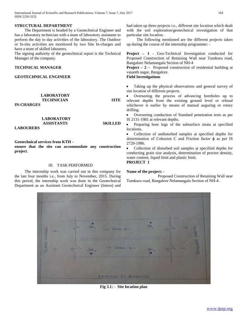
had taken up three projects i.e., different site location which dealt with the soil exploration/geotechnical investigation of that particular site location. The following mentioned are the different projects taken up during the course of the internship programme: - Project – 1 - Geo-Technical Investigation conducted for Proposed Construction of Retaining Wall near Tumkuru road, Bangalore Nelamangala Section of NH-4 Project – 2 – Proposed construction of residential building at vasanth nagar, Bangalore. Field Investigations • Taking up the physical observations and general survey of site location of different projects. • Overseeing the process of advancing boreholes up to relevant depths from the existing ground level or refusal whichever is earlier by means of manual auguring or rotary drilling. • Overseeing conduction of Standard penetration tests as per IS 2131-1981 at relevant depths. • Preparing bore logs of the subsurface strata at specified locations. • Collection of undisturbed samples at specified depths for determination of Cohesion C and Friction factor ɸ as per IS 2720-1986. • Collection of disturbed soil samples at specified depths for conducting grain size analysis, determination of proctor density, water content, liquid limit and plastic limit. PROJECT 1 Name of the project: - Proposed Construction of Retaining Wall near Tumkuru road, Bangalore Nelamangala Section of NH-4 .
Fig 3.1: - Site location plan

International Journal of Scientific and Research Publications, Volume 7, Issue 7, July 2017 105 ISSN 2250-3153
www.ijsrp.org
Soil samples obtained: - Disturbed and undisturbed soil samples are obtained in the field. • TESTS REPORTS ON SOIL SAMPLES: - SIEVE ANALYSIS BORE HOLE 1:-
Table no 3.1:- Results on sieve analysis of Borehole 1
BH. No.
Depth in m Gravel in %
Sand in % C M F
Silt and clay in %
Liquid limit in %
Plastic limit in %
Plasticity index
1 2.0 17 07 31 18 27 26 18 08
1 3.5 4 05 42 30 19 32 20 12
1 5.5 4 02 30 33 31 40 24 16 SOIL CLASSIFICATION (IS: 1498– 1970):- IS OF SILTY SAND WITH CLAY BINDER FOR BOREHOLE 1 AT ALL DEPTH BORE HOLE 2
Table no 3.2:- Results on sieve analysis of Borehole 2 BH. No.
Depth in m Gravel in %
Sand in % C M F
Silt and clay in %
Liquid limit in %
Plastic limit in %
Plasticity index
1 2.0 17 07 31 18 27 26 18 08
1 3.5 4 05 42 30 19 32 20 12
1 5.5 4 02 30 33 31 40 24 16 SOIL CLASSIFICATION (IS : 1498– 1970):- IS OF SILTY SAND WITH CLAY BINDER FOR BOREHOLE 2 AT ALL DEPTH BORE HOLE 3
Table no 3.3:- Results on sieve analysis of Borehole 3 BH. No.
Depth in m Gravel in %
Sand in % C M F
Silt and clay in %
Liquid limit in %
Plastic limit in %
Plasticity index
3 2.0 04 04
35
22
35 44 30 14
3 3.5 05 03
44
21
27 38 26 12
3 5.5 32 15
27
11
15 24 NP Nil
SOIL CLASSIFICATION (IS : 1498– 1970):- SILTY SAND WITH CLAY BINDER FOR DEPTH 2m &3.5m, SILTY SAND WITH GRAVEL FOR DEPTH 5.5m. BORE HOLE 4
Table no 3.4: - Results on sieve analysis of Borehole 4 BH. No.
Depth in m Gravel in %
Sand in % C M F
Silt and clay in %
Liquid limit in %
Plastic limit in %
Plasticity index
4 2.5 16 12 31 16 25 28 20 08
4 4.0 01 08 38 20 33 30 20 10
4 5.5 03 03 23 40 31 28 18 10

International Journal of Scientific and Research Publications, Volume 7, Issue 7, July 2017 106 ISSN 2250-3153
www.ijsrp.org
SOIL CLASSIFICATION (IS: 1498– 1970): - SILTY SAND WITH CLAY BINDER FOR ALL DEPTH DIRECT SHEAER: -
Table no 3.5:- Results on Direct shear test of Borehole 1 to Borehole 4 Normal stress in kg/cm2
Shear stress in kg/cm2
0.5 0.65
1.0 1.2
1.5 1.7
BH No
Depth in m
C T/m2
0
1.Ch:17+350 RHS
1.5 0.60 25
2.Ch:17+150 RHS
1.5 0.30 26
3.Ch:17+150 LHS
1.5 0.40 26
4.Ch:17+350 LHS
1.5 0.30 26
Table no 3.6: - C and ɸ values COMPACTION TEST
Table no 3.7: - Results on Compaction test of Borehole 1 to Borehole 4
BH. No.
Depth in m
Field Moisture Content %
b kg/m3
d kg/m3
Optimum Moisture content in %
Maximum dry density kg/m3
1.Ch:17+350 RHS
1.5 7.80 1.85 1.69 12 1.87
2.Ch:17+150 RHS
1.5 9.79 1.96 1.78 12 1.85
3.Ch:17+150 LHS
1.5 10.19 1.82 1.67 12 1.88
4.Ch:17+350 LHS
1.5 9.15 1.87 1.74 12 1.85

International Journal of Scientific and Research Publications, Volume 7, Issue 7, July 2017 107 ISSN 2250-3153
www.ijsrp.org
MDD for borehole 1
BORELOGS

International Journal of Scientific and Research Publications, Volume 7, Issue 7, July 2017 108 ISSN 2250-3153
www.ijsrp.org

International Journal of Scientific and Research Publications, Volume 7, Issue 7, July 2017 109 ISSN 2250-3153
www.ijsrp.org

International Journal of Scientific and Research Publications, Volume 7, Issue 7, July 2017 110 ISSN 2250-3153
www.ijsrp.org

International Journal of Scientific and Research Publications, Volume 7, Issue 7, July 2017 111 ISSN 2250-3153
www.ijsrp.org
DESIGN OF FOUNDATION FOR BOREHOLE 1 (According to I S 6403:1981) AT DEPTH 1.5m qa= C’N’cScdcic + ɣDf(N’q-1)Sqdqiq +0.5BɣN’ɣSɣdɣiɣW + ɣDf FS

International Journal of Scientific and Research Publications, Volume 7, Issue 7, July 2017 112 ISSN 2250-3153
www.ijsrp.org
qa =Safe Bearing Capacity in T/m2, FS=Factor of Safety - 2.50 Bf =Width of Foundation -1.00m Df=Depth of Foundation -4.75m As furnished by the customer W’ = Correction Factor for Water table = 1.00 W’ = Correction Factor for Water table = 1.00 C = 0.60 T/m2 , C =0.40 T/m2 , = 25, = 17, =1.69g/cc Nc = 12.520 Nq = 4.924 N = 3.746 W‘=1.00 Sc =1.00 Sq =1.00 S = 1.00 ic = 1.00 iq =1.00 i = 1.00 • dc = 1+ 0.2 D √N B √N = tan2 (3.14/4+ /2) N = tan (45+ /2) dc= 1+ 0.2 D √N = 1.06 B dq = d = 1+ 0.1 D tan (45+ /2) = 1.03 B qa = (0.40x12.52x1.0x1.06x1)+(1.69x1.5x(4.9241)x1.0x1.03x1)+(0.5x4.75x1.69x3.746x1.0x1.03x1x1.00) +{(1.69x 1.0 ) (2.50) qa =14.00T/m2 AT DEPTH 3m qa= C’N’cScdcic + ɣDf(N’q-1)Sqdqiq +0.5BɣN’ɣSɣdɣiɣW + ɣDf FS qa=16.00T/m2 DESIGN OF FOUNDATION FOR BOREHOLE 2 (According to I S 6403:1981) AT DEPTH 1.5m qa= C’N’cScdcic + ɣDf(N’q-1)Sqdqiq +0.5BɣN’ɣSɣdɣiɣW + ɣDf FS qa = (0.40x12.52x1.0x1.06x1)+(1.69x1.5x(4.9241)x1.0x1.03x1)+(0.5x4.75x1.69x3.746x1.0x1.03x1x1.00) +{(1.69x 1.0 ) (2.50) qa =13.00 T/m2 SETTLEMENT AS PER IS: 8009 (Part I) for Strip footing For N=15, B=1.5m As per Fig.9 of IS: 8009 (Part I) Settlement = 1.70x 10⁻³(m) x 1.3x 100x 10 = 22.1mm < 25mm Hence adopt SBC= 13.00 T/m2 AT DEPTH 3m qa= C’N’cScdcic + ɣDf(N’q-1)Sqdqiq +0.5BɣN’ɣSɣdɣiɣW + ɣDf FS qa =16.00 T/m2 DESIGN OF FOUNDATION FOR BOREHOLE 3

International Journal of Scientific and Research Publications, Volume 7, Issue 7, July 2017 113 ISSN 2250-3153
www.ijsrp.org
(According to I S 6403:1981) AT DEPTH 1.5m qa= C’N’cScdcic + ɣDf(N’q-1)Sqdqiq +0.5BɣN’ɣSɣdɣiɣW + ɣDf FS qa = (0.40x12.52x1.0x1.06x1)+(1.69x1.5x(4.9241)x1.0x1.03x1)+(0.5x4.75x1.69x3.746x1.0x1.03x1x1.00) +{(1.69x 1.0 ) (2.50) qa =14.00 T/m2 AT DEPTH 3m qa= C’N’cScdcic + ɣDf(N’q-1)Sqdqiq +0.5BɣN’ɣSɣdɣiɣW + ɣDf FS qa =16.00 T/m2
DESIGN OF FOUNDATION FOR BOREHOLE 4 (According to I S 6403:1981) AT DEPTH 1.5m qa= C’N’cScdcic + ɣDf(N’q-1)Sqdqiq +0.5BɣN’ɣSɣdɣiɣW + ɣDf FS qa = (0.40x12.52x1.0x1.06x1)+(1.69x1.5x(4.9241)x1.0x1.03x1)+(0.5x4.75x1.69x3.746x1.0x1.03x1x1.00) +{(1.69x 1.0 ) (2.50) qa =14.00 T/m2 AT DEPTH 3m qa= C’N’cScdcic + ɣDf(N’q-1)Sqdqiq +0.5BɣN’ɣSɣdɣiɣW + ɣDf FS qa =16.00 T/m2

International Journal of Scientific and Research Publications, Volume 7, Issue 7, July 2017 114 ISSN 2250-3153
www.ijsrp.org
IV. RECOMMANDATIONS BOREHOLE 1:- From the field and laboratory investigation, Gravel = 04 to 17%, Sand = 56 to 77%, Silt & Clay= 19 to 31%, Liquid Limit = 26 to 40% and the Plasticity Index= 8 to 16. The N value is 5 at 2.0m, 21 at 3.5m and 41 at 5.5m depth.
Depth below ground level(m) SBC in T/m2 Types of foundation suggested
1.5 14.0 Strip foundation
3.0 16.0
The Safe Bearing Capacity values at different depths are given below. Table no 3.8: - Recommendation on Borehole 1 BOREHOLE 2: - From the field and laboratory investigation, Gravel = 0 to 5%, Sand = 40 to 77%, Silt & Clay=23 to 55%, Liquid Limit = 30 to 32% and the Plasticity Index= 10 to 12. The N Value is 15 at 2.0m, 19 at 3.5m and 34 at 5.5m depth. The Safe Bearing Capacity values at different depths are given below.
Table no 3.9: - Recommendation on Borehole 2
Depth below ground level(m) SBC in T/m2 Types of foundation suggested
1.5 13.0 Strip foundation
3.0 16.0
BOREHOLE 3: - From the field and laboratory investigation, Gravel = 4 to 32%, Sand = 53 to 68%, Silt & Clay=15 to 35%, Liquid Limit = 24 to 44% and the Plasticity Index= 12 to 14 up to 4.5m and Non plastic at 5.0m. The N Value is 11 at 2.0m, 17 at 3.5m and 95 at 5.5m depth The Safe Bearing Capacity values at different depths are given below.
Table no 3.10: - Recommendation on Borehole 3
Depth below ground level(m) SBC in T/m2 Types of foundation suggested
1.5 14.0 Strip foundation
3.0 16.0
BOREHOLE 4 :- From the field and laboratory investigation, Gravel = 1 to 16%, Sand = 59 to 66%, Silt & Clay=25 to 31%, Liquid Limit = 28 to 30% and the Plasticity Index= 8 to 10. The N Value is 16 at 2.0m, 19 at 3.5m and 30 at 5.5m depth. The Safe Bearing Capacity values at different depths are given below.

International Journal of Scientific and Research Publications, Volume 7, Issue 7, July 2017 115 ISSN 2250-3153
www.ijsrp.org
Table no 3.11: - Recommendation on Borehole 4
Depth below ground level(m) SBC in T/m2 Types of foundation suggested
1.5 14.0 Strip foundation
3.0 16.0
PROJECT 2 Name of the project: - Proposed construction of residential building at vasanth nagar, Bangalore.
Fig 3.2:- Site location plan
Soil samples obtained: - Disturbed and undisturbed soil samples are obtained in the field. • TEST REPORTS ON SOIL SAMPLES: - SIEVE ANALYSIS BORE HOLE 1
Table no 3.12: - Results on sieve analysis of Borehole 1
BH. No.
Depth in m Gravel in %
Sand in % C M F
Silt and clay in %
Liquid limit in %
Plastic limit in %
Plasticity index
1 2.0 01 09 27 23 40 24 NP NIL
1 3.5 05 13 27 20 35 28 18 10
1 5.5 - 02 32 22 44 24 NP NIL SOIL CLASSIFICATION (IS : 1498– 1970):- SILTY SAND AT DEPTH 2m & 5.5m, SILTY SAND WITH CLAY BINDER AT DEPTH 3.5m

International Journal of Scientific and Research Publications, Volume 7, Issue 7, July 2017 116 ISSN 2250-3153
www.ijsrp.org
BORE HOLE 2 Table no 3.13: - Results on sieve analysis of Borehole 2
BH. No.
Depth in m Gravel in %
Sand in % C M F
Silt and clay in %
Liquid limit in %
Plastic limit in %
Plasticity index
2 2.0 - 15 35 22 28 28 20 08
2 3.5 05 17 39 16 23 28 NP NIL
2 5.5 06 19 26 17 32 26 NP NIL SOIL CLASSIFICATION (IS : 1498– 1970):- SILTY SAND WITH CLAY BINDER AT DEPTH 2M & 5.5M, SILTY SAND AT DEPTH 3.5m
DIRECT SHEAR: -
Table no 3.14: - Results on Direct shear test of Borehole 1 Normal stress in kg/cm2
Shear stress in kg/cm2
0.5 0.65
1.0 1.2
1.5 1.7
Table no 3.15: - C and ɸ values
BH No
Depth in m
C T/m2
0
1 1.5 0.50 29
2 1.5 0.40 30
COMPACTION TEST
Table no 3.16: - Results on Compaction test of Borehole 1 to Borehole 2
BH. No.
Depth in m
Field Moisture Content %
b kg/m3
d kg/m3
Optimum Moisture content %
Maximum dry density kg/m3
1 1.5 4.62 1.69 1.62 12 1.87
2 1.5 8.45 1.79 1.65 12 1.85
BORELOGS

International Journal of Scientific and Research Publications, Volume 7, Issue 7, July 2017 117 ISSN 2250-3153
www.ijsrp.org

International Journal of Scientific and Research Publications, Volume 7, Issue 7, July 2017 118 ISSN 2250-3153
www.ijsrp.org
DESIGN OF FOUNDATION FOR BORE HOLE 1 and 2 (According to I S 6403:1981) AT DEPTH 1.5m qa= C’N’cScdcic + ɣDf(N’q-1)Sqdqiq +0.5BɣN’ɣSɣdɣiɣW + ɣDf FS
International Journal of Scientific and Research Publications, Volume 7, Issue 7, July 2017 119 ISSN 2250-3153
www.ijsrp.org
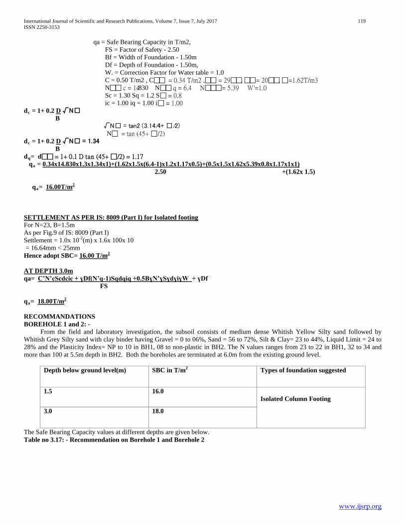
qa = Safe Bearing Capacity in T/m2, FS = Factor of Safety - 2.50 Bf = Width of Foundation - 1.50m Df = Depth of Foundation - 1.50m, W. = Correction Factor for Water table = 1.0 C = 0.50 T/m2 , C = 0.34 T/m2 , = 29, = 20, =1.62T/m3 N c = 14.830 N q = 6.4 N = 5.39 W'=1.0 Sc = 1.30 Sq = 1.2 S = 0.8 ic = 1.00 iq = 1.00 i = 1.00 dc = 1+ 0.2 D √N B √N = tan2 (3.14/4+ /2) N = tan (45+ /2) dc = 1+ 0.2 D √N = 1.34 B dq= d = 1+ 0.1 D tan (45+ /2) = 1.17 qa = 0.34x14.830x1.3x1.34x1)+(1.62x1.5x(6.4-1)x1.2x1.17x0.5)+(0.5x1.5x1.62x5.39x0.8x1.17x1x1) 2.50 +(1.62x 1.5) qa= 16.00T/m2 SETTLEMENT AS PER IS: 8009 (Part I) for Isolated footing For N=23, B=1.5m As per Fig.9 of IS: 8009 (Part I) Settlement = 1.0x 10⁻²(m) x 1.6x 100x 10 = 16.64mm < 25mm Hence adopt SBC= 16.00 T/m2
AT DEPTH 3.0m qa= C’N’cScdcic + ɣDf(N’q-1)Sqdqiq +0.5BɣN’ɣSɣdɣiɣW + ɣDf FS qa= 18.00T/m2
RECOMMANDATIONS BOREHOLE 1 and 2: - From the field and laboratory investigation, the subsoil consists of medium dense Whitish Yellow Silty sand followed by Whitish Grey Silty sand with clay binder having Gravel = 0 to 06%, Sand = 56 to 72%, Silt & Clay= 23 to 44%, Liquid Limit = 24 to 28% and the Plasticity Index= NP to 10 in BH1, 08 to non-plastic in BH2. The N values ranges from 23 to 22 in BH1, 32 to 34 and more than 100 at 5.5m depth in BH2. Both the boreholes are terminated at 6.0m from the existing ground level.
Depth below ground level(m) SBC in T/m2 Types of foundation suggested
1.5 16.0 Isolated Column Footing
3.0 18.0
The Safe Bearing Capacity values at different depths are given below. Table no 3.17: - Recommendation on Borehole 1 and Borehole 2

International Journal of Scientific and Research Publications, Volume 7, Issue 7, July 2017 120 ISSN 2250-3153
www.ijsrp.org
V. CONCLUSION On the whole, this internship programme was a useful experience which helped to gain new knowledge, skills and met many new people and got insight into professional practice and also learned the different facets of working within consultancy. The field investigation helped to understand the physical observation and general survey of the site location and also different methods of sampling and subsurface explorations whereas laboratory investigation has enhanced expertise of different laboratory experiments as per I.S codes. At the start of internship work in the company, was aware of only the theoretical knowledge of the works and some practical knowledge regarding laboratory experiments. It was really fascinating and inspiring to see and experience the lessons learnt been put to use in practice. This opportunity will definitely be a big milestone in the career development and help to do better in the future endeavors. Gained skills and knowledge would be put to use in the best possible way, and would continue to work on their improvement, in order to attain desired career objectives and express more confidently. Internship program brought me good theoretical and practical knowledge, also the good knowledge about the design and their implementation in or off the site. At last this internship has given a new insights and motivations to pursue a career in geotechnical engineering in India or abroad.
REFERENCES [1] “Soil Mechanics and Foundation Engineering – Geotechnical Engineering”
by Dr K.R. ARORA [2] Soil mechanics and foundations by B.C PUNMIA, ASHOK KUMAR
JAIN, ARUN KUMAR JAIN. [3] IS : 2720(Part 4) – 1985 Methods of test for soils : Part 4 Grain size
analysis [4] IS : 2720(Part 5) – 1985 Methods of test for soils : Part 5 Determination of
Liquid and Plastic Limit [5] IS : 2720(Part 7) – 1980 Methods of test for soils : Part 7 Determination of
water content- dry density relation using light compaction [6] IS : 2720(Part 8) – 1983 Methods of test for soils : Part 8 Determination of
water content- dry density relation using heavy compaction [7] IS : 2720(Part 13) – 1986 Methods of test for soils : Part 13 Direct shear test [8] IS : 2720 (Part 29)-1975 Methods of Test for Soils : Part 29: Determination
of Dry Density of Soils in-place by the Core-cutter Method [9] IS: 9640 (1980): Split Spoon Sampler [10] IS 6403 (1981): Code of practice for determination of bearing capacity of
shallow foundations [11] IS 8009-1 (1976): Code of practice for calculation of settlements of
foundations, Part 1: Shallow foundations subjected to symmetrical static vertical loads
AUTHORS First Author – Ranajith Aithal G, East West Institute of Technology, Bangalore-62 Second Author – Mr. Kiran, East West Institute of Technology, Bangalore-62