john mathes & associates inc - summary report … · summary report field investigation paxton...
TRANSCRIPT

(•". I"
261555
SUMMARY REPORT FIELD INVESTIGATIONPAXTON AVENUE LAGOONS
CHICAGO, ILLINOISDecember 9, 1985
DEC 111985
IEPA-DLPC
JOHN MATHES & ASSOCIATES, INC.210 Woat Sand Bank Road
P.O. Box 330Columbia, IL 62236
riathe
John Mathes & Associates, Inc.

TABLE OF CONTENTS
Page #
INTRODUCTION 1
PHASE I
Personnel Affiliation and Responsibilities 3Pre-lnvestigation Data Collection Site Visits 4Initial Site Reconnaissance • 4Air Quality 4Site Safety 5Site Zone Delineation 6Documentation 6Contaminant Containment 7Topographic and Elevation Control 7Site Conditions and Quantities Surveys 8Sampling 9Main Lagoon 9Skimmer Lagoon 10Soil/Crushed Drum Berm 11Contaminated Soil Area 11Raised Area 12Factors Influencing Work Product 12
PHASE II
Personnel Affiliation and Responsibilities 13Phase II - Introduction 13Initial Site Reconnaissance 13Air Quality 14Site Safety 15Non-Agency (Supplier) On-Site Visitors and Supplies 16Site Zone Delineation 17Documentation • 17Contaminant Containment 17Topographic and Elevation Control 18Site Condition and Quantities Surveys 18Sampling 19Main Lagoon • 19Skimmer Lagoon 21South Pond 21Soil/Crushed Drum Berm 22Contaminated Soil Area 22Filled In Area 23Seepage Area 23Raised Area 24QA and QC Samples 24Factors Influencing Work Product 25
name
John Mathes & Associates, Inc.

TABLE OF CONTENTS CON'T
ILLUSTRATIONS
Figure 1: Site Location
Figure 2: Immediate Area of Site
Figure 3: Project Area and Access Restriction Zones
Figure 4: Final Sample Locations
APPENDICES
Appendix A: Pre-Investigation Data
Appendix B: Exploration/Sampling Logs-Test Pit Logs-Lagoon Liquid/Sludge Logs
Appendix C: Analytical Data
Appendix D: Paxton Avenue lagoons - Site Log (Book)
Appendix E: Photo Log Index Key
Appendix F: IEPA Background Analytical Data-Raised Area Soils Analysis
Appendix G: Dioxon Analytical Data-Lagoons/South Pond Sludge/SedimentComposite Sample
John Mathes & Associates, Inc.

INTRODUCTION
John Mathes & Associates, Inc. (JMA), conducted a fieldinvestigation of the Paxton Avenue Lagoons area locatedapproximately at 122nd Street and Paxton Avenue, Chicago,Illinois (Figures 1 & 2). Field work was performed at therequest of the Illinois Environmental Protection Agency (IEPA) inorder to characterize surface and subsurface contamination in thenear vicinity of the subject waste disposal lagoons. Theinvestigation was conducted in two phases, the latter programbeing initiated due to changed conditions for Phase I field work.Phase I was performed June 24 through July 3, 1985; Phase II fromAugust 8 through 19, 1985.
Site characterization work was a multiple task investigationprogram which encompassed various technical disciplines. Ambientair quality was measured and monitored. Liquids were sampled andvolumes estimated for the Main and Skimmer Lagoons. See Figure 3for site sampling areas. Sludge and/or bottom sediments weresampled in the lagoons and South Pond. Surface and subsurfacesoils and contaminant materials were sampled as encounteredduring field operations. The quantity and distribution ofchemical products and/or containers were surveyed and roughlyestimated. Easily accessible chemical specimens were sampledwhen discovered. General site conditions were observed andrecorded in a field log book for site activities. Appendix D isa xerox copy of the original field log book. Photographicdocumentation of sample collection locations and specific siteconditions of potential environmental contamination wasperformed. Appendix E is the photo log index key list for sitep h o t o s p r o v i d e d . A r e a s of k n o w n or s u s p e c t e denvironmental/health hazard were delineated and visually markedto limit unauthorized access. Topographic and elevation controlsfor site features and sampling points were developed from aerialreconnaissance photography and surface transit survey (See Figure4). Data detailing the extent and level of contamination to thesubject area was generated from chemical analyses of samplescollected (See Appendix C).
The following text will present a brief discussion of siteactivities, observations, and achievements during the separatephases of the field investigation. Emphasis will be placed onsite conditions and activities in relation to the projectwork/sampling plan, and on the accomplished work product. It isnot the intent of this document to provide either a chronologicalor detailed description and/or discussion of specific siteactivities. Also neither specific data generated nor subsequentinterpretation or inferences from collected or generated data areprovided in text discussions. Finally, the followinginvestigative phase discussions will not evaluate field teamperformance of anticipated field procedures and schedules beyondrelative success or completion percentage. The reader should
name
John Mathes & Associates, Inc.

Page 2
note that all field activities undertaken were done so underdirection of specifically developed project phase sampling plansand site safety plans, as well as established industry standardpractice. The reader is referred to these documents for desiredsupplemental information. For the reader's use and convenience,all collected and generated data from the field investigationwill be provided as appendices to this report in lieu of anydetailed or specific discussions.
viathc
John Mathes & Associates, Inc.

Page 3
PAXTON FIELD INVESTIGATION - PHASE I
Field Operations - June 24 Through July 3, 1985
Personnel A f f i l i a t i o n And Responsibilities
NAME
A.J. Hoyt
G. Nash
COMPANY/TITLE(POSITION)
JMA/Hydrogeologist
JMA/Geological Technician
C. Harriss
T. Fuhrhop
K. Hileman
M. Dinkel
M. Levine
JMA/Manage r-Dr i11i ng
JMA/Drilling Foreman
JMA/Drilling Technician
lEPA/Site Representative
IEPA/Project Coordinator
J. Janssen lEPA/Project Engineer
J. Franks IEPA
C. Floyd IEPA
L. Bennet IEPA
C. Gruntman IEPA
E. Linn IEPA
B. Wiatrolek IEPA
D. Smith Paxton Landfill/Manager
R. Nowicki & Nowicki & Associates, Ltd.two Assistants
ACTIVITIES
Project coordinator, site safetyo f f i c e r , f i e l d s a m p l e r ,documentation.
Site safety back-up, equipmentand instrumentation maintenance,f i e l d s a m p l e r , d e c o ncoordination
Drilling/Sampling coordination
Drilling, sampling
Dri l l ing , sampling backhoeoperator
On-site observer , p ro j ec tcoordination and documentation
In-house project coordination,site visitor
Site visitor
Site visitor
Site visitor
Site visitor
Site visitor
Site visitor
Site visitor
Site visitor
Surveyors
E. Prendergast City of Chicago, Dept. of Site visitorEnvironmental Control
riathc
John Mathes & Associates, Inc.

Page 4
Pre-Investigation Data Collection Site Visits
Previous to any JMA site investigation activities, two sitev i s i t s were made to collect or genera te data for s i te a c t i v i t yp l a n n i n g . M. K r o e n i g of J M A , and J. Janssen and M. D i n k e l ofI E P A v i s i t e d the s i te on May 14 , 1985, to d e t e r m i n e s i tec o n d i t i o n s a n d c h a r a c t e r i z a t i o n r e q u i r e m e n t s f o r p r o j e c tp l a n n i n g , schedul ing and cost e s t i m a t i o n . On June 3, 1985, M.Dinkel of IEPA collected one surface l iquid sample each f rom theM a i n and S k i m m e r Lagoons , and the South Pond. Sample a n a l y s i swas p e r f o r m e d by E n v i r o d y n e Eng inee r s , Inc. 's a n a l y t i c a l lab ofS t . L o u i s , M i s s o u r i . A n a l y t i c a l r e s u l t s a r e p r o v i d e d i nAppendix C.
In i t ia l Site Reconnaissance
D u r i n g t h e i n i t i a l s i t e v i s i t o n J u n e 2 4 , 1985, J M Arepresen ta t ives A.J. Hoyt and G. Nash met w i t h D. S m i t h , P a x t o nL a n d f i l l M a n a g e r , a n d d i s c u s s e d g e n e r a l s i t e h i s t o r y a n dconditions. A pre l iminary site survey was conducted as a "walk-through" recon at a sa fe d i s tance f r o m po ten t ia l a i r b o r n ec o n t a m i n a n t s . Site access, zones of r e s t r i c t i o n due to s a f e t yh a z a r d s , and s p e c i f i c si te c o n d i t i o n s were noted. The ve ry lowlevel of navigable f lu ids w i th in the lagoons and South Pond wasnoted i m m e d i a t e l y . Based on the s a m p l i n g p l an u t i l i z i n g boatsand a f loa t ing d r i l l ing p l a t fo rm to sample these areas, problemsd u e t o " f l o a t i n g " s a m p l i n g l o c a t i o n s a c c e s s i b i l i t y w e r ean t i c ipa t ed . A.J. Hoyt repor ted th i s changed c o n d i t i o n to thea p p r o p r i a t e JMA r ep re sen t a t i ve and I E P A contact . M. K r o e n i g ,JMA Project Engineer relayed this i n f o r m a t i o n to IEPA managementfor potential m o d i f i c a t i o n s to anticipated field activit ies. Af o l l o w - u p w a l k - t h r o u g h o f t h e s i te w i t h t h e I E P A s i t erep resen ta t ive , M . D i n k e l , a n d J M A d r i l l i n g personnel v e r i f i e dthe probable need for changed f i e l d s a m p l i n g me thodo logy .However, the planned boat sampling approach was attempted u n t i lan a l t e r n a t e me thod was selected. Two a l t e r n a t e m e t h o d s w e r eimplemented, one attempted on the Sk immer Lagoon, and the otherused o n t h e M a i n L a g o o n . U l t i m a t e l y t h e b o a t m e t h o d w a sabandoned for sampl ing both the Sk immer Lagoon and South Pond.
Air Quality
An in i t i a l site survey was conducted immedia te ly f o l l o w i n gthe site recon to determine the general ambient air qual i ty. JMApersonne l , accompan ied by the I E P A represen ta t ive M. D i n k e l ,conducted the m o r e de ta i led , tho rough site recon in order toe s t a b l i s h t h e s p e c i f i c l e v e l ( s ) o f need f o r r e s p i r a t o r ypro tec t ion for on-si te ac t iv i t i es . (Note: For a l l subsequen td i s c u s s i o n , i t w i l l be assumed tha t the IEPA r e p r e s e n t a t i v e , M.D i n k e l , w a s p r e s e n t a s e i t h e r a n o b s e r v e r o r v o l u n t a r yaccompanying pa r t i c ipan t du r ing al l JMA on-site act ivi t ies unless
John Mathes & Associates, Inc.

Page 5
specifically noted otherwise.) Both a Foxboro OVA (organic vapora n a l y z e r ) and an HNU p h o t o i o n i z a t i o n detector were u t i l i z e d tocha rac t e r i ze po ten t ia l gas or vapor m i s t r e s p i r a t o r y haza rds .The i n i t i a l site air q u a l i t y survey, conducted on a w a r m , sunnyd a y , f o u n d the s i t e to be r e l a t i v e l y f r e e o f v o l a t i l econtaminants. The survey, conducted under Level C (respirator)p ro tec t ion , es tabl ished tha t r e s p i r a t o r s p rov ided adequa tepersonnel p ro tec t ion in the v i c i n i t y of the M a i n and S k i m m e rLagoons and for s i te w o r k in genera l . H o w e v e r , the South Pondwas an except ion in tha t a i r - b o r n e vo la t i l e s were detectedd o w n w i n d ad jacen t to the pond in c o n c e n t r a t i o n s h i g h enough topose a potential health hazard.
Spec i f i c si te a c t i v i t i e s p rov ided a d d i t i o n a l evidence fo rincreased r e sp i r a to ry p r o t e c t i o n beyond Level C r e sp i r a to r s .S t i r r i n g of pond s e d i m e n t s of the Sou th Pond, consp icous lylittered w i t h decomposed d rum debris, produced relatively highreadings on air qual i ty instruments . Later sampl ing act ivi t iesin the Soil/Crushed Drum Berm exposed a very high organic vaporconcentration necessitating up-graded respira tory protection forthat specific location. Bottom sediment probing in the M a i n andS k i m m e r L a g o o n s p r o d u c e d v a p o r c o n c e n t r a t i o n s v a l i d a t i n gprecautions for constant a i r qua l i ty m o n i t o r i n g du r ing samplinga c t i v i t i e s i n those loca t ions . I n p a r t i c u l a r , m o n i t o r i n g fo rhydrogen sulf ide, hydrogen cyanide and cyanide salts, as well asgeneral o r g a n i c vapor c o n c e n t r a t i o n s , was conducted a lmostc o n t i n u o u s l y d u r i n g f i e l d ope ra t i ons where p o t e n t i a l exposureand/or release of con taminan t s was suspected. Chemical -speci f icm o n i t o r i n g was provided w i t h color imet ic a i r sampl ing (Draeger)tubes.
Site Safety
P r e l i m i n a r y s a f e t y p r e c a u t i o n s w e r e t o u s e L e v e l Crespiratory protection wi th f u l l dermal protection and emergencysupplied-air egress equipment for all si te sampl ing operationsu n t i l p roven o t h e r w i s e . H i g h h a z a r d m o n i t o r i n g was to beprov ided c o n s t a n t l y , and the p o s s i b i l i t y for Level B ( supp l i eda i r ) p ro t ec t i on was suspect. I n i t i a l and subsequent f i e l dactivit ies showed that Level B protection was necessary f o r : 1)All sampl ing act ivi t ies on or immedia te ly d o w n w i n d of the SouthPond , and 2) Test pi t l oca t i on # 04-5 of the S o i l / C r u s h e d D r u mBerm. The need to p r o v i d e level C p r o t e c t i o n w i t h emergencym o n i t o r i n g / e g r e s s c a p a b i l i t y f o r o the r s i te a c t i v i t i e s w a smainta ined. Level D (dermal) protection was thought adequate forall other on-site (non-hot zone) act ivi t ies . Personal sampl ingpumps w i t h f i l ters for air-borne heavy metals and PCB's were tobe worn where these contaminants were suspect.
name
John Mathes & Associates, Inc.

Page 6
Site Zone Delineat ion
A highly visible boundary to the known and/or suspect zonesof chemica l h a z a r d was es tabl ished. D r i v e n steel fence postswere ins ta l l ed and m a r k e d w i t h f l u o r e s c e n t r ed woven p l a s t i cbarr icade tape around the: 1) Ma in Lagoon, 2) Skimmer Lagoon, 3)South Pond , 4 ) So i l /Crushed D r u m B e r m , and 5) The C o n t a m i n a t e dSoil Area immedia te ly west of the Sk immer Lagoon. Addi t iona l ly ,the decontaminat ion /support areas for both the lagoons and SouthPond areas were es tab l i shed w i t h c o n t r a s t i n g b a r r i c a d e r i b b o nf l a g g i n g . The i n t e n t of this bar r icade r ibbon "fence" was top r o v i d e a c lear ly v i s i b l e w a r n i n g of h a z a r d areas as opposed toestablishing a t rue "barrier" to physical access.
Documentat ion
Two p r i m a r y fo rms of documenta t ion were provided by JMA forsi te a c t i v i t i e s , a f i e l d log and photo records. The p r i n c i p a ldocumentat ion was accomplished using a dedicated f ield log bookto record a l l p e r t i n e n t da ta and i n f o r m a t i o n about the f i e l dinvestigation. An attempt was made to judiciously and f a i t h f u l l yrecord all facts and f igures possible, per the fo rma t prescribedin the Phase I Sampl ing Plan. E f f o r t s have been made to provides u p p l e m e n t a l , pos t -ac tua l f i e l d a c t i v i t y da ta whe re on-s i tea c t i v i t i e s and pe r sonne l l i m i t a t i o n s precluded total, detai led"on-the-spot" d o c u m e n t a t i o n .
C e r t a i n b a s i c a r e a s o f d o c u m e n t a t i o n w e r e s t r i c t l ym a i n t a i n e d w i t h i n the f i e l d log book on a d a i l y basis. A d a i l ylog of specif ic site ac t iv i t i es including personnel on-site, worka c c o m p l i s h e d , a n d n o t a b l e o b s e r v a t i o n s , w a s s u b - h e a d e dindiv idual ly . Specific sampling points , procedures, and samplen u m b e r s w e r e recorded. W r i t t e n photo logs f o r a c t i v i t i e s o rr e l e v a n t f e a t u r e s not i n t ended to be sampled (bu t of poss ib lee n v i r o n m e n t a l s i g n i f i c a n c e ) we re recorded when p i c t u r e s we retaken . A i r q u a l i t y m e a s u r e m e n t s and o ther s i te s a f e ty re la tedconcerns were noted when d i f f e r i n g f rom established norms.
A supplemental documenta t ion was provided using photographicdocumentat ion w i t h a 35 mm SLR camera. The intent was to providea p h o t o g r a p h i c record of: 1) All s a m p l i n g l o c a t i o n s - d e t a i l i n gnearby and dis tant , d i s t inc t ive physical and/or cu l tura l fea turesthus f a c i l i t a t i n g re-location of the sampl ing point d u r i n g f u t u r esite visi ts ; 2) Site condi t ions pr ior to, du r ing , and a f t e r sitea c t i v i t i e s ; and 3 ) S p e c i f i c s i te c o n d i t i o n s n o t e w o r t h y o fpossible addi t ional f ie ld inves t iga t ion or concern for accuratesite character izat ion, especially when s igni f icant ly outside thecurrent scope of act ivi t ies .
nathc
John Mathvs & Associate*, Inc.

Page 7
Contaminant Containment
During all field operations, a specifically designated,dedicated area of the site was set-up as a contaminantcontainment and reduction zone or decontamination area. Thisdecon area was established in conjunction with a field activitiessupport area, both areas being jointly located on the Raised(soil pad) Area in the southwest corner of the Main Lagoon. ThisRaised Area is believed to be either a permanent or latter lagoondisposal operation staging pad for heavy equipment, possiblydragline equipment and disposal truck off-loading.
The field operations support/decon area consisted of fiveseparate functional facilities: 1) An equipment storage andpreparation area, 2) A worker safety suiting and rest area, 3) Asample preparation and packaging area, 4) A personneldecontamination reduction line, and 5) A heavy field equipmentand sampling/drilling supplies decon area. The latter deconfacility was specifically sited to promote natural drainage ofdecon soap wash and rinse waters back into the Main Lagoon via ashallow depression gently sloping towards the lagoon at thesouthwest corner of the lagoon. The intent of the siteactivities support/decon area was to: 1) Restrict personnelaccess to a relatively "clean" area of the site while not suitedfor dermal protection, thereby minimizing worker exposure to sitecontaminants, 2) Provide a centralized location for supportactivities, and 3) Establish a decon facility to limit andcontain contaminant migration from the site hot zones as well asequipment used for field operations and sampling within those hotzones. All personnel and equipment used or entering in thedesignated hot zones were required to be deconned prior to exitor removal from the site support area.
Topographic and Elevation Contrcxl
JMA retained the services of Surdex Corporation ofChesterfield, Missouri, to develop topographic and elevationcontrol for field investigation activities. Surdex in turnprovided a local surveying company, Nowicki and Associates, Ltd.of Chicago, Illinois to locate site control points. JMApersonnel established several baselines to develop a referencinggrid pattern for sampling point map locations. End points ofthese baselines were tied into the overall mapping effort bySurdex and Nowicki and Associates.
Initially, four grid baselines, two each traversing roughlynorth-south and east-west, were established by the JMA fieldteam. One line ran east to west along the top of the high soilberm adjacent to the north edge of the Main Lagoon. A secondline, approximately perpendicular to the first, crossed the eastend of both the Main and Skimmer Lagoons in a north to southdirection. A third line ran east to west roughly parallel to the
John Mathes & Associates, Inc.

Page 8
first, and was Located just to the south of the Skimmer Lagoon,being almost tangent to the lagoon at its southwest point. Thefinal line was established in an approximate north to southdirection and was located on the raised berm area immediatelyflanking the South Pond along its eastern edge. Sampling pointswere located on the site topo map based largely on topographicand cultural features, with some reference to the site photo log.
Site Conditions and Quantities Surveys
Two initial site surveys were performed by JMA personnel inorder to assist field operations planning and coordination.First, the site was inspected as to the accessibility of fieldoperations equipment, especially vehicular traffic. Routes ofon-site travel were established to minimize traffic acrosscontaminated materials, and prevent damage and loss time frompotentially immobilized field equipment. Also, the ability touse the sampling boats/drilling platforms on the lagoons wasascertained as to accessibility once on lagoon liquid surfaces.Secondly, a rough field survey was conducted in order to quantify(by rough estimation) the potential removable contaminants in: 1)Liquid materials of the lagoons, and 2) Drums visible within thelagoons and Soil/Crushed Drum Berm areas.
Liquid material(s) quantities were found to be difficult tomeasure and estimate, and also were insufficient to facilitatesampling platform movement. The Skimmer Lagoon proved to havelittle or no liquid material, excluding occasional rainwater.The sampling/drilling platform, once dragged by truck to itsinitial sampling location on the Skimmer Lagoon, was effectivelymired at that location for the duration of all site activities.The sampling platform was abandoned at its launch point.
The Main Lagoon was initially probed as one of the finalactivities of the Phase I investigation. Probing was done withthin-walled metal electrical conduit (pipe) at six (6) locationsalong the south edge of the Main Lagoon. Each probing locationwas accessible by either a plywood sheet or a flat-bottomed'"John" boat positioned with one end on the lagoon bank forstability. Probing found that: 1) On average, liquids wererelatively thin near the lagoon banks, 2) The lagoon banks werenot steep-sided but rather were sloped and highly irregular inconfiguration, and 3) Significant volatile organic vapors werereleased from bottom sediments during probing, confirming theneed for respiratory protection for lagoon sampling activities.
The South Pond was found to be almost drained (or dried-up)of free standing water. Furthermore, a large quantity of drumsand drum debris were found within the drained pond bottom.Planned sampling efforts with the boats for the South Pond areahad to be abandoned for an alternative method.
name
John Mathes & Associates, Inc.

Page 9
Drum quantities, although of significant number, proved tobe a rather meaningless concern. Overall, excluding occasionalplastic drums, the vast majority of all drums observed wereeither crushed or decomposed beyond fluid holding capability.The large number of drums within the South Pond contained littlebeyond minimal liquids probably trapped from higher fluid levelsdue to spring time rain water collection in the pond. The vastmajority of contaminants that may have existed in those drumshave most likely been released to the pond waters and underlyingsediments. Approximately 120-150 drums were clearly visiblewithin the pond depression.
The north-south trending Soil/Crushed Drum Berm and anirregular, debris area on the west side of the South Pond bothcontained a significant number of drums but all or nearly alldrums appeared to be severely crushed. Although not asdecomposed as the South Pond drums, again, the potential forcontainment of chemical products within the drum debris isminimal. Estimation of quantities was difficult due to theburied nature of crushed drums. Overall, approximately 100 plusdrums were visible directly or from excavation with a backhoe.However, evidence from digging suggests that the vast majority ofcrushed drums still remain buried and inestimable.
Occasional drums were also visible within the Main Lagoonarea. A few drums were stuck in shallower lagoon liquid/sludgewhile some crushed drums were visible in the lagoon retainingsoil berms. The potential for non-visible drums within thefluids and sludge of the main lagoon existed but were largelyinestimable at that time. One drum was believed to have beenencountered in the six random probe locations tested along thesouth Main Lagoon edge.
Sampling
S a m p l i n g e f f o r t s d u r i n g Phase I a c t i v i t i e s u t i l i z e d av a r i e t y o f me thods f o r several u n i q u e l y d i s t i n c t i v e s a m p l i n gareas. S a m p l i n g methodo logy was selected to o p t i m i z e sampleaccuracy and e f f i c i e n c y in the f i e l d in d i r ec t reponse tospecific env i ronmenta l and/or subsurface conditions. Therefore,d i scuss ion of s a m p l i n g specif ics w i l l be addressed on an areaspecific basis.
Main Lagoon
S a m p l i n g e f f o r t s f o r t he M a i n Lagoon area were l a rge lyd e l e t e d d u r i n g Phase I due to m o b i l i t y p r o b l e m s o f t hes a m p l i n g / d r i l l i n g p l a t f o r m because o f the low lagoon f l u i dlevels. Only one sampling location 01-1-1 (Refer to Final SampleLocations plan, Figure 4, for all sample locations discussed) wassampled u s i n g a J o h n boat p a r t i a l l y beached on the lagoon bank .S u r f a c e oi l was dipped w i t h a s t a in l e s s steel (SS) ladle and
John Mathes & Associates, Inc.

Page 10
: :ansferred d i rec t ly to a q u a r t glass sample jar . A 2 inchL a m e t e r clear plast ic excelon tube was then hand pushed andledge hammer-dr iven to refusal at approximately 9.5 feet. Theample tube was retr ieved by both d r i l l e r s us ing great e f f o r t• i t h p ipe wrenches . (Note: A Lagoon L i q u i d / S l u d g e log was• r e p a r e d f o r a l l M a i n L a g o o n p u s h t u b e s a m p l i n g / p r o b i n gocat ions . See Append ix B for all f i e l d s a m p l i n g logs.) Theube was emptied of f lu ids , and the under ly ing sludge and bottom-lost soil were containerized separately. The samples collected;ere stored for later composit ing.
M. Dinke l of IEPA collected a composi te sample of the)i I/sludges of both the Main and Skimmer Lagoons, and the South>ond s u r f a c e "muck" on Ju ly 3, 1985. T h i s sample was s u b m i t t e d:o Envirodyne Engineers, Inc., lab for D i o x i n analysis. Results>£ this analysis are provided in Appendix G.
Skimmer Lagoon
Sampling of the Skimmer Lagoon was l imited to three of theD r i g i n a l l y p lanned s ix loca t ions . The loca t ions sampled andLogged we re 02-1-3, 02-1-4, 02-1-5. The m a x i m u m depth ofp e n e t r a t i o n was a p p r o x i m a t e l y 15 ' in test hole 02-1-4, w h i l eno les ranged f r o m a p p r o x i m a t e l y 9 ' to 15' deep. Samples w e r ecollected for materials recovered f rom and mixed for each depthincrement of f ive feet s tar t ing f rom the lagoon surface. A totalo f seven s a m p l e s w e r e c o l l e c t e d a n d s t o r e d f o r f u t u r ecompositing.
S a m p l i n g me thodo logy w a s m o d i f i e d three t imes d u r i n gse imp l ing e f f o r t s i n t he S k i m m e r Lagoon . I n i t i a l l y , e f f o r t s t od ip - sample s u r f a c e m a t e r i a l s was re j ec ted due to very h i g hmater ia l viscosity. Next sampling by advancing 2 inch diameterexcelon tube through a 3" diameter pvc pipe outer casing by handwas a t tempted. A f t e r cons ide rab le e f f o r t , t he hole was re -started us ing the cat-head r ig th rough the d r i l l i n g p l a t f o r m .E x c e l o n t u b i n g , s ta in less steel (SS) sp l i t spoon samplers , andthe pvc casing were then advanced w i th the 140 pound split-spoonh a m m e r . W h e n the d r i l l i n g p l a t f o r m was f o u n d to be m i r e d a tlocation 02-1-3, the cat-head rig was setup on plywood sheets tosample the next location, 02-1-4. When recurring problems withspl i t spoons j a m m i n g inside the pvc casing aga in l imi ted the testh o l e d e p t h , t h e f i n a l s p l i t s p o o n w a s s a m p l e d / d r i v e n t oapproximate ly 15' wi thou t the pvc casing. Based on lesser casinghang-up problems wi th the excelon tube in comparison to the splits;poon sampler, the f ina l location, 02-1-5, was sampled w i th thecat-head rig, setup on plywood, d r i v i n g push tubes only.
The physical na tu re of the ma te r i a l s encountered in theS k i m m e r Pond caused severe s a m p l i n g problems. The d r i l l i n gplat form/boats were abandoned when found to be stuck in the heavysurface sludge - much like tar. Sampling access was possible by
nathc
John Mathe* & Asvociates, Inc.

Page 11
l a y i n g p lywood sheets on the s ludge / lagoon s u r f a c e . H o w e v e r ,most equipment used in the sampling e f fo r t was abandoned due tothe h i g h cost of l abo r ious decon of the " t a r ry" m a t e r i a l s . Asplit-spoon hammer was abandoned for this reason.
Soil/Crushed Drum Berm
S a m p l i n g was done in ten (10) loca t ions , n u m b e r e d 04-1through 04-10, scattered along and around the nor th -sou thtrending Soil/Crushed Drum Berm. Sampling of buried subsurfacemater ia l s was possible by excavation of test pits w i t h a Case 580backhoe opera ted by K. H i l e m a n . A.J. H o y t sampled m a t e r i a l sw i t h i n the test pits using dedicated SS spoons placing materiald i r e c t l y i n t o 250 ml amber glass j a r s . One l o c a t i o n , 04-5,r e q u i r e d u s e o f Leve l B ( s u p p l i e d a i r S C B A ) r e s p i r a t o r yprotection for sampling.
In general , mater ia ls encountered w i t h i n the test pi ts wereh i g h l y v a r i a b l e bu t were largely ash, soi l and debr i s . W h e ne n c o u n t e r e d , v i s i b l e chemica l m a t e r i a l s w e r e p r e f e r e n t i a l l ysampled instead of soils. This occurred in locations 04-4, 04-5,0 4 - 6 , a n d 0 4 - 7 . S o i l s / a s h w e r e c o l l e c t e d i n each o f t h er e m a i n i n g test pits . A d d i t i o n a l l y , 04-7 was soi l s a m p l e d andnumbered 2143-04D1-7A. These samples were submit ted to the labon "hold" status. Add i t i ona l soil m a t e r i a l collected in testpits were composited and submitted for analyses. Soils f r o m 04-1, 04-2, and 04-3 became composite #2143-0401-11. Soils f r o m 04-7A, 04-8, 04-9, and 04-10 became composite #2143-04D1-12.
Contaminated Soil Area
A soi l compos i t e sample was collected f r o m the "o i ly"Contaminated Soil Area immediately west of the Skimmer Lagoon.F ive separa te loca t ions ( s h o w n as p lus ( + ) symbols on the F i n a lSample Locat ion plan, Figure 4) were sampled ind iv idua l ly into ac o m m u n a l SS bowl w i t h a SS spoon, and w e r e m i x e d u n i f o r m l y andcontainerized as sample #2143-05SS-6 in a 250 ml amber glass jar.Each l o c a t i o n sampled was m a r k e d w i t h a d r i v e n 2 x 2" hub . Thesample was sent to an anlytical lab, Envi rodyne Engineers of St.Louis , M i s s o u r i for analysis immedia te ly f o l l o w i n g Phase I f i e ldoperations.
In order to determine shallow sub-surface soil condi t ions inthe C o n t a m i n a t e d Soil Area , A.J. Hoy t dug three test holes byshovel to approximately one foot in depth. Buried chemical pastewas encountered in one hole w h i l e buried sludge was found in theo ther two holes; one as a t h i n seam, the o the r as the b o t t o mm a t e r i a l w i t h o u t ind ica t ion to extent d o w n w a r d .
name
John Mathes & Associates, Inc.

Page 12
Raised Area
At the request of M. Dinkel, site representative for theIEPA, two shallow test holes were dug approximately 6" deep by G.Nash in the site support/decon area. One 250 ml jar sample wascollected from the ash/soil/cinder material in each of the testholes. The samples were submitted to M. Dinkel, and wereanalyzed by Aqua Lab, Inc. of Bartlett, Illinois under directionof IEPA directly. The samples were found to contain high levelsof contaminants, especially lead dust and chlordane pesticidewell as other heavy metals. Results of these analysesprovided in Appendix F.
asyses are
No other sampling work was accomplished within the timeschedule constraints of the Phase I investigation. The majorityof anticipated sampling activities was omitted at that time dueto invalid or inefficient methodology from changed environmentalconditions. No efforts were made to sample any drums.
Factors Influencing Work Product
The ultimate work product of the Phase I field investigationwas severely hampered by unanticipated field working conditions.Fluid level recessions within the lagoons and South Pond: 1) Madesampling with the sampling/drilling platform virtually impossibleat that time, 2) ultimately caused the drilling platform tobecome permanently mired in the Skimmer Pond, 3) Delayed workprogress by loss of the drilling platform and need to work by"hand", and 4) Deleted sampling of the pond due to lost fieldtime from delays. Additionally, unexpected high temperaturescreated a heat stress problem. Severely decreased workefficiency, coupled with lost field time while mobilizingoperations for the transition from first to third shift drillingand sampling activities, detracted from the total work product.Regrouping for a second phase operation became necessary. JMAand IEPA arranged to meet to plan and schedule future fieldactivities.
nathc
John Mathes & Associates, Inc.

Page 13
PAXTON FIELD INVESTIGATION - PHASE II
Field Operations - August 8 through 19, 1985
Personnel A f f i l i a t i o n and Responsibil i t ies
NAME OOMPANY/TITLE(POSITION) ACTIVITIES
A.J. Hoyt JMA/Hydrogeologist Project coordinator, site safetyo f f i c e r , f i e l d s a m p l e r ,documentat ion
G. Nash JMA/Geological Technician Site safety backup, equipment andinstrumentation maintenance, fieldsampler, decon technician
M. Kosydor JMA/Drilling Coordinator Dr i l l i ng , sampling and deconc o o r d i n a t i o n , f i e l d sampler ,technical assistance
D. Gotto JMA/Drilling Foreman
M. Dinkel lEPA/Site Representative
M. Levine lEPA/Project Coordinator
Backhoe operator
O n - s i t e o b s e r v e r , p r o j e c tcoordination and documentation
In-house project coordination,visitor
site
R. Wiatrolek lEPA/Public Relations Site visitor to video tape site& Assistant & Communications Team sampling
Phase II - Introduction
The content of each Phase II specific subject discussioncan be accepted as being fully salient or in agreement with itscorresponding specific subject content from Phase I discussionunless otherwise noted. The topic will either be: 1) Fullyagreed to or pertinent, 2) Modified by addition or deletion orboth, 3) Irrelevant and changed altogether, or 4) Immaterial andcompletely deleted. In each case, the intent will be clearlystated at the beginning of the Phase II discussion.
Initial Site Reconnaissance
Another initial site recon was necessary at the outset ofPhase II field operations. Additional information was requiredto determine: 1) Vehicle accessibility for the extra testpit/sampling locations to the west of the Main Lagoon added tothe scope of work, 2) The extent of modifications to andadditional materials necessary to re-define and delineate theextended "hot" zone boundary barricade tape west of the MainLagoon, 3) The amount of air line equipment necessary to setup
name
John Mathes & Associates, Inc.

Page 14
Level B ( supp l i ed a i r - a i r l i n e ) r e s p i r a t o r y p r o t e c t i o n fors a m p l i n g personnel to a l l a n t i c i p a t e d loca t ions , and 4) Thevis ib le lateral extent of chemical con taminant seeps extendingwestward , m i g r a t i n g f r o m the M a i n Lagoon and Filled In Area ( s ) .
The concerns listed in the previous paragraph were addressedand answered in the f o l l o w i n g manner :
1. A " w a l k o v e r " of the sub jec t s a m p l i n g l oca t i ons w i t h i nthe Fil led-In and Seepage areas, general sampl ing areasd e s i g n a t e d a s 0 6 a n d 0 7 , r e s p e c t i v e l y , f o u n d t h elocations readi ly accessible to the excavat ion backhoe.
2. A "paced" m e a s u r e m e n t of the new ex ten t of the "hot"zone b o u n d a r y b a r r i c a d e tape f e n c i n g r e q u i r e m e n t s a n da i r l ine needed determined that pre-site es t imates wereaccurate and adequate enough to require no m o d i f i c a t i o n sto e x i s t i n g m a t e r i a l supp l i e s or orders . The b o u n d a r yb a r r i c a d e w a s m o d i f i e d t o encompass t h e n e w s a m p l i n gareas.
3. A visual survey d u r i n g a nor thwestern site "walk-over"w i t h M . D i n k e l o f I E P A f o u n d ev idence o f c o n t a m i n a n tm i g r a t i o n al l the way to the edge of the r a i s e d oldPaxton L a n d f i l l area. These observat ions were recordedand p h o t o g r a p h e d , and w e r e r epor ted to M. K r o e n i g , JMAProject Manager so that the w o r k scope and sampl ing plancould be m o d i f i e d if so desired by IEPA.
Air Qual i ty
Al l the a i r q u a l i t y i n f o r m a t i o n presented in Phase I i sf u l l y app l i cab le a n d r e l e v a n t f o r Phase I I c o n s i d e r a t i o n . T h ef o l l o w i n g areas o f a d d i t i o n a l a i r q u a l i t y i n f o r m a t i o n a r egeneral ly in the rea lm of site safety m o d i f i c a t i o n s w i t h spec i f i creference to resp i ra tory protect ion.
Based on the s a m p l e a n a l y s i s r e su l t s for the two soilsamples col lected fo r and a n a l y z e d by the I E P A fo r the o r i g i n a ls i te suppor t and decon a r e a , inc reased concern fo r r e s p i r a t o r yp r o t e c t i o n a n d p e r s o n a l e x p o s u r e m o n i t o r i n g f o r a i r b o r n en o n v o l a t i l e c o n t a m i n a n t s w a s n e c e s s a r y d u r i n g P h a s e I Ia c t i v i t i e s . P e r s o n a l a i r s a m p l i n g p u m p s w i t h e i t h e r a PCB orheavy metals f i l te r were used when work was done in areas stilldes igna ted for Level C ( r e s p i r a t o r ) p ro t ec t i on . A l s o , the needto w e a r r e s p i r a t o r s due to h i g h w i n d c o n d i t i o n s on-s i t e was ada i ly f ie ld call by the JMA and IEPA Safety Representatives. Thespecific need was never ordered dur ing Phase II operat ions. Theuse of m i n i m u m Level D ( d e r m a l ) p r o t e c t i o n for a l l on - s i t eac t iv i t ies on foot was s t r i c t ly required for Phase II ac t iv i t ies .
name
John Mathes & Associates, Inc.

Page 15
D u e t o t h e a n t i c i p a t e d p o t e n t i a l r e lease o f l a r g ec o n c e n t r a t i o n s o f h i g h h a z a r d v o l a t i l e a n d / o r v a p o r o u sc o n t a m i n a n t s d u r i n g test p i t e x c a v a t i o n s w i t h the backhoe , a l ls i te e x c a v a t i o n and s a m p l i n g o p e r a t i o n s were p e r f o r m e d unde rLevel B ( s u p p l i e d air - air l i n e ) r e s p i r a t o r y p ro tec t ion .C o n t i n u o u s a i r q u a l i t y m o n i t o r i n g w a s n o t r e q u i r e d b y s a f e t yrequi rements under Level B but was ma in ta ined when and whereverposs ib le in order to p r o v i d e a d d i t i o n a l da ta about p o t e n t i a la i rborne con taminan t release d u r i n g f u t u r e r e m e d i a l e x c a v a t i o nwork .
Based on the documented Phase I organic vapor release d u r i n ge x c a v a t i o n of the Soi l /Crushed D r u m Berm test pi t 04-5 , and thesubsequent exposure and physical response of a JMA worker who wasi m m e d i a t e l y d o w n w i n d d u r i n g t he release, t he test p i t was a i rsampled w i th a co lor imet r ic chemically-sensi t ive Draeger tube forphosgene. This con taminan t , suspected to have been released, wasnot present when tested for on August 8, 1985.
It should be noted that the presence of cyan ides as s o d i u mand/or potassium salts of cyanide was c o n f i r m e d d u r i n g sampl ingof the Skimmer Lagoon in both invest igat ion phases. The hydrogens u l f i d e mon i to r / a l a rm may have been m o m e n t a r i l y tripped in thesame area du r ing Phase II excavation.
Site Safety
Safety precautions for Phase II operations were upgradedoverall in comparison to Phase I protection. Dermal protectionfor Level C and B were identical while minimal Level D dermalprotection was required for all on-site activities in Phase IIwork. Where Level C respiratory protection was still deemedadequate, the same air quality monitoring requirements andemergency egress equipment was available.
The majority of sampling work and backhoe excavation wasdone by workers equipped with supplied air with air-linerespirator equipment and cascade air tank supply systems. Onecascade system was established in a mobile trailer so that itcould be moved by pickup truck to the vicinity of sampling andback to the site delivery air cylinder drop locationapproximately 40 - 50 feet south of the southeast corner of theSkimmer Lagoon. This system was set up to supply sampling,safety, and documentation personnel with breathing air, andprovide a hook-up for the sample processing and/or decontechnician, if deemed necessary. The need for this backupcapability never materialized. A second cascade system was setup in the backhoe cab for the operator so that he could maintainfull mobility. All air-line respirator equipment was providedwith an "in-line" emergency egress 5-minute air bottle system.Because no operational alarm system existed on the air supplysystem, a technician was available at all times to respond
John Mathes & Associates, Inc.

Page 16
immediately to an on-site emergency or low air supply. Thistechnician also had equipment available to make an emergency"hot" zone ingress if necessary. During Phase II samplingoperations, no "true" emergency situations occurred to require anemergency egress or ingress. However, the backhoe operator didmake one evacuation from the backhoe cab on his 5 minute egressair bottle when his cascade system air cylinder ran out of airduring excavation of one test pit, #07-2.
A self contained breathing apparatus (SCBA) supplied airsystem was kept on site as a back-up system for emergencysituations, and as the air supply for resampling Soil/CrushedDrum Berm test pit #04-5. The SCBA was used briefly for thelatter purpose only.
As referenced previously under air quality, personal airsampling pumps with either PCB or heavy metals filters were usedfor potential personal exposure monitoring during the limitedLevel C operations in the vicinity of the Main Lagoon.
Finally, site sampling activities were considered in orderto avoid any recurrence of work progress efficiency problems dueto heat stress, such as those encountered during Phase I samplingactivities. Phase II sampling activities (excluding theSoil/Crushed Drum Berm resampling) were planned, mobilized andcarried out during evening and night time hours. Late shifthours also helped alleviate concerns for problems from wind blownparticulate contaminants. In general, winds in the site vicinitydecreased substantially or were virtually nonexistent during thenight time, excluding storm activity.
Non-Agency (Supplier) On-Site Visitors and Supplies
Due to the necessity for delivery and pickup of equipmentand supplies for Phase II investigation activities, concern forpotential exposure to delivery personnel and off-site transportof site contaminants arose in light of the IEPA background soilsanalyses findings. The decision was made and enforced jointly byJMA and IEPA to either protect returnable equipment/supplies orprovide decon• of such items if exposed to any contaminantconcentrations of significant concern. Air cylinders wereprotected by storage on plastic sheeting and transport on-siteeither in a pickup truck bed, the cascade trailer bed, or insidethe backhoe cab. The rental cascade trailer was kept off of andaway from any grossly contaminated materials. The rental backhoewas steam-cleaned two complete times in order to remove allgrossly contaminated materials encountered during excavation oftest pits and backfilling operations. All other rental gear on-site was cleaned and deconned prior to return. Supplier'sdelivery personnel were not allowed site access beyond the aircylinder drop point near the Skimmer Lagoon.
name
John Mathes & Associates, Inc.

Page 17
Site Zone Delineation
The areas delineated as to potential or known chemicalhazard and marked as such by high visibility boundary barricaderibbon for an access restriction warning during Phase I weremaintained for Phase II operations with the followingmodifications. The section of boundary fencing running north-south along the berm on the western end of the Main Lagoon wasremoved and replaced with boundary barricade fencing extendingwestward to the western site edge. This new area enclosesobserved contaminant seeps and materials seen all the way to thesurface dropoff to the adjacent western landfill property. Also,the initial site support/decon area was included as part of thehot zone based on IEPA lab results.
Documentation
Literary and photographic documentation procedures, format,and methodology for Phase II operations were in strict agreementwith those followed for Phase I activities. All samplinglocations were marked with clearly labelled wooden stakes andphotographed to verify specific location.
Additionally, photographic documentation of the physicalcondition of the rental backhoe used for test pit excavation wasthoroughly performed before and after field use. A copy of eachset of photos was provided to the rental company, the former setsent by certified mail delivery timed and dated to prove pre-existing backhoe defects and damages prior to use. A copy ofboth sets of photos were also provided to IEPA. The purpose ofthis photographic documentation was to provide photographicevidence detailing preexisting rental unit conditions asliability protection against unwarranted claims for damagesduring unit use on-site. JMA also wished to provide validationfor legitimate claims potentially possible for damages caused byexcavation of highly acidic or corrosive materials known to existon-site, as well as to protect IEPA from illegitimate claims.There were no claims by the rental agency.
Contaminant Containment
Phase II operations established a site support/deconfacility at a different location than that from Phase I. Theprimary logic behind location setup and the facility design wasessentially the same with these notable modifications. First,the location was selected to move off of the Raised Area, aformer location found to contain significant health hazard fromknown contaminants. The new location was on soil of a largelydiffereing physical and material nature. Second, the newlocation, being located right at the entrance to the site area,was convenient as a drop point for site-delivered supplies and
Yiafhc
John Mathes & Associates, Inc.
Page 18
equipment. Third, the location is conducive to limiting siteaccess and potential exposure to delivery personnel and hiredsecurity guards. Fourth, the location was in a pivotal positionfor access to all site sampling locations. Fifth, an enclosedsafety equipment and personnel suiting/resting station (a tent)was set up to provide protection from the elements. Also, theconcerns for containment and channeling of deconned contaminantsand spent decon fluids were drastically modified for Phase II.Due to the relatively high level of ambient contaminants in ashand cinder laden soils on-site, an area of similar soil materialwas selected adjacent to both the staging/sample prep/personneldecon area and the Skimmer Lagoon. Spent, nonchemical deconfluids were not anticipated to contribute any significantaddition to the contaminants already present on-site. Finally,based on the relatively crude method of sampling chosen, and theintent to composite much of the materials to be sampled, the needto decon the backhoe bucket between sampling locations within anarea to be composited was deemed unnecessary. Furthermore, deconof the bucket between specific sampling areas was adequatelyachieved by thoroughly digging and stirring the bucket intosurface soils of the next area to be sampled.
Topographic and Elevation Control
The Phase I discussion remains fully pertinent and appliableto Phase II requirements. No further discussion is required.
Site Condition And Quantities Surveys
The following additional points of discussion combined, withthe applicable discussion from Phase I provide a completediscussion for the Phase II investigation. The only relevantaddition to site conditions discussion was that mentioned underinitial site recon. Site conditions were inspected and recordedin regards to: 1) Vehicular access to new sampling locations, 2)Surface evidence of previously unobserved environmentalcontamination (ie. seeps), and 3) New boundary limits for themodified site restriction/delineation barricade ribbon fencing.
Additional activities were performed by JMA personnel inorder to provide more data to that acquired during Phase Iinvestigation of fluid quantities within the Main Lagoon. Ninemore locations in the eastern lagoon half, a deeper area of moreextensive liquids, were probed with either a hand-pushed 2 inchdiameter excelon sampling tube while sampling or a metal thin-walled electrical conduit. Probing by hand push only, not sledgehammer-driven probes, showed a depth range of from approximately3 to 6.5 feet. Drums were believed to have been encounteredwhile probing two of the nine locations.
John Mathes & Associates, Inc.

Page 19
U n f o r t u n a t e l y , s eve re d i f f i c u l t y i n m o v i n g s a m p l i n gpersonnel and equ ipmen t in the J o h n boat on the M a i n Lagoonprevented more extensive f l u i d probing activit ies, especially forthe data poor western area of the M a i n Lagoon.
Sampling
As per the Phasewill be dealt with on
Main Lagoon
I discussions, Phase II sampling activitiesan area specific basis.
Phase II sampling within the Main Lagoon was limited tosampling of four probe locations during the liquid quantitiesprobing survey, and hand dipping two surface soil samples. Thefour probe locations, designated 01-BS-l through Ol-BS-4 (referto Figure 4, Final Sample Locations Plan) were sampled by hand-pushed (to refusal) and retrieved 2" diameter excelon tubing.The tubes were left in the original, Phase I decon area untilcomposited at the end of all field sampling operations. Surfaceoil samples were hand-dipped with a SS ladle at locations Ol-L-6.
The following summarizes the fate of the oil/sludge samplescollected during both Phase I and II samplings. The upper fluidmaterials from locations 01-1-1 and Ol-BS-4 were composited toform Ol-BL-5, while fluids from 01-BS-l through Ol-BS-3 werecomposited to form Ol-BL-6. The lower sludge materials fromlocations 01-1-1 and Ol-BS-4 were composited to form Ol-S-5,while sludges from 01-BS-l through Ol-BS-3 were composited toform Ol-S-6. "Soil-like" material encountered in the bottom oflocation 01-1-1, approximately 9 - 9.5 deep, was containerizedindividually as sample #2143-01BS-I-1. Liquid samples collectedat locations 01-L-5&6 were submitted individually. All sampleswere submitted to Envirodyne Engineers, Inc., for chemicalanalyses.
Seven (7) test pits were excavated around and adjacent tothe Main Lagoon. Test pit 01-1 was located at the south end of ashallow north-south depression, at the southwest corner of theMain Lagoon's west end. Five test pits, locations 01-2 through01-6 were dug in the Raised (soil pad) Area, generally adjacentto the lagoon fluid surface but within the bank material toprevent inflow of lagoon surface liquids.
Note: For all test pit sampling locations excavated with thebackhoe during Phase II operations, the intended samplinglogic was to collect material from each test pit asrepresentative material of the strata encountered and tocomposite like materials from all or predesignated sets oftest pits w i t h i n each sampling area. The threematerials/strata generally anticipated to be encounteredwere: 1) Overlying relatively uncontaminated fill or cover
name
John Mathes & Associates, Inc.

Page 20
material, 2) Heavily contaminated either buried or lateralseepage materials from the lagoons, and 3) Relativelyuncontarninated underlying either fill soils, earlierlandfill, or possibly natural materials. These threematerial or strata zones were designated as Dl, D2, andD3, respectively, in all sampling nonenclature. Exceptfor two locations in the Raised Area of the Main Lagoon,which were thick, relatively uniform, uncontaminatedmaterials overlying concrete or "concrete-1 ike" weldedash material, the upper (Dl) zone was generally terminatedat or near the five foot depth. The middle (D2) zonerarely extended to its maximum ten foot depth. The bottom(D3) zone reached a maximum excavation depth of 14 feetonly twice. When unique subsurface conditions wereencountered in test pits, an additional sample wouldusually be taken, especially where heavy chemicalcontamination was suspect. In general, there is nodirect, strict stratigraphic correlation of material typeor depth between samples collected within the Dl, D2, andD3 sampling zones beyond the general 0-5 feet, 5-10 feet,and greater than 10 feet, respectively, planned samplingintervals.
"sub-zone"As many
The reader should also note that when additional sampleswere collected within a test pit, the strata sampled wasassigned the next "D" designation or a uniquedesignation to preserve stratigraphic sequence,as five samples were collected from one 14 foot depth testpit by this method. Also, it should be noted that, forthe unique conditions encountered during test pitexcavations for Paxton-Phase II, the far more commondecision was to retain, for individual analysis, theuniquely dissimilar samples from each test pit exhibitingvastly differing strata.
The six Main Lagoon - Raised Area test pits ranged in bottomdepth from approximately 4.5 to 13.5', and, generally,encountered silty material overlying very hard, compacted orcemented slag material, "concrete-like" in density. Refusal tofurther excavation terminated all but one Main Lagoon area testpit. Buried landfill rubbish was seen in the bottom of two pits,and only one pit had a trickle of chemical liquid into the pit atdepth, in the rubbish material.
The samples collected from each depth interval of pits 01-1through 01-3 were composited to produce composite samples #2143-01D1-8 and #2 143-01D2-8. The samples collected from pits 01-4through 01-6 as "full depth" samples were composited to formsample #2143-01D1-9.
nathc
John Mathes & Associates, Inc.

Page 21
The final test pit dug near the Main Lagoon, 01-7 wasexcavated into the eastern face of the high berm immediately eastof the lagoon. This test pit was excavated to characterizematerials used to construct the high berms enclosing the MainLagoon. The excavation extended several feet into the berm froma point approximately eleven of the estimated 15 foot berm heightdown to a level approximately even with the land surface at thatlocation. In general, materials in the berm were silty mixedconstruction/rubble debris. The three samples collected weresubmitted individually for analysis.
One noteworthy observation was recorded during excavation ofTest Pit 01-7. While digging during the very cool (approximately50OF.) and humid night, a very dense release of white vapor wasencountered in the hole. Materials encountered within the bermwere found to be warm to hot to the touch, even through multiplelayers of protective gloves. It is believed that the white vaporrepresents water vapor in the night air that entered the openexcavation. However, no explanation has been offered to explainthe high internal heat feature of the berm itself.
Skimmer Lagoon
Three test pits, 02-1 through 02-3, were excavated adjacentto the south and eastern Skimmer Lagoon edges within the bankmaterials, again to avoid chemical sludge inflow. The test pitsranged in depth from approximately 10.5 to 14 feet. Each testpit proved to be uniquely different, and all samples collectedwere submitted individually for analysis. One pit encounteredwhat appeared to be zones of buried sludge material very similarto that found in the Skimmer Lagoon borings from Phase I.Another pit encountered what appeared to be a chemical sludgeseep zone. The last pit found mixed silty material and landfillrubbish overlying hard, compacted, cemented material causingexcavation refusal at 11'.
South Pond
A total of four test pi ts were excavated to charac ter ize theSouth Pond c o n t a m i n a t i o n . Three test p i t s , 03-1 t h r o u g h 03-3,located a round the pond body edge, were excavated to depthsranging f r o m approx ima te ly 3.5 to 7 feet into the pond sediments .I n gene ra l , m a t e r i a l s encoun te red w e r e o r g a n i c " m u c k " soi lso v e r l y i n g v a r i o u s f i l l m a t e r i a l s , m o s t l y debr i s , a n d some purec h e m i c a l paste. Crushed d r u m s w e r e encoun te red in two o f thethree pits. Two pits were terminated due to r e fusa l on submergedconcre te slabs, w h i l e the t h i rd was t e r m i n a t e d due to s i d e w a l lf a i l u r e into the pi t negat ing fu r the r excavat ion gain. The f l u i dlevel f r o m w a t e r w i t h i n t h e pond s e d i m e n t s / m u c k r a n g e d f r o mi m m e d i a t e l y be low to a p p r o x i m a t e l y 1.5' be low the s e d i m e n tsurface. Two samples were collected at each test pit locat ion.
Yiathe
John Mathes & Associates, Inc.
Page 22
The fourth test pit, 03-4, was excavated transverse to theinlet channel gully immediately upgradient of the pond body. Thetest pit was dug approximately 14' deep and encountered highlyvariable and contaminated materials, including a thin zone ofchemical paste. A total of five samples were collected.
Based on the highly variable nature of materials encounteredin the South Pond test pits, and the wide ' "sampled, all samples collected from thisindividually for analysis.
rangearea were
of depthssubm i t ted
Soil/Crushed Drum Berm
Four of the test pits excavated in the Soil/Crushed DrumBerm during Phase I operations were resampled during Phase II.The chemical specimens collected previously from pits 04-4through 04-7 were found to be of insufficient quantity forlaboratory analysis. Therefore, these locations were resampledto provide additional testing material, and were submittedindividually for analysis. In order to distinguish the Phase IIsamples from the Phase I samples, an additional post scriptnumeral, "-1", was added to the original Phase I sample numbersconverting them to Phase II sample numbers.
Contaminated Soil Area
One test pit was excavated in the approximate center of theContaminated Soil Area immediately west of the Skimmer Lagoon.The location was selected to be approximately centered withrespect to the five surface soil sampling points of the Phase Isoil composite sample #2143-0553-6. These composite samplingpoints appear as plus ( + ) symbols on Figure 4. The Test Pit wasdug to a depth of approximately 10.5 feet where refusal wasencountered on very hard, "cemented" material. Overlyingmaterials were mixed and layered, silty and "chalk-like", andincluded landfill rubbish in the lower pit zone. Three zoneswere sampled and submitted individually for analysis.
Two notable observations were recorded for the contaminatedsoil zone during Phase II operations. First, in one of the threeshallow pits hand dug during Phase I, a "lava-like" inflow ofsludge was observed and photographed upon return to the locationfor Phase II. Second, the backhoe had severe difficulty movingaround on or across the main body of the Contaminated Soil Area.The surface materials appeared to be relatively loose, lowdensity silty ash material underlain at a depth of approximately6" to one foot by either softer or sludgy material. The backhoefoundered badly, became nearly mired, and almost tipped over fromrutting under the drive tires. Traverse of the area causedsevere rutting. Ironically, no sludge material was encounteredin the backhoe dug test pit.
Yiathc
John Mathes & Associates, Inc.

Page 23
Filled In Area
Based on aerial photography provided by C. G r u n t m a n of IEPAd u r i n g Phase I operat ions, s ampl ing ac t iv i t i es for Phase II wereextended to the areas wes tward f r o m the M a i n Lagoon. E x a m i n a t i o no f pho tographed l a n d f i l l o p e r a t i o n s f r o m b e f o r e t h e d i sposa lf a c i l i t y was closed suggests that the area i m m e d i a t e l y west ofthe M a i n Lagoon may have been f i l l e d in . The area appeared tohave been the west end of the o r i g ina l M a i n Lagoon. This area isnow a ra ised , n e a r l y level soil and deb r i s f i l l m a t e r i a l area.The o r i g i n a l M a i n L a g o o n p r o b a b l y ex tended a d i s t a n c e of 75 to100' w e s t w a r d of the e x i s t i n g M a i n lagoon w e s t e r n edge. Thephotographs also suggest that an area of probable or ig ina l M a i nLagoon seepage f l u i d s ex i s t ed f u r t h e r w e s t w a r d ou t beyond theo r i g i n a l e x t e n t o f t he M a i n Lagoon . T h i s seepage zone e x t e n d sthe area of concern an a d d i t i o n a l 75 to 100* w e s t w a r d , thusextending the increased area of inves t iga t ion approx ima te ly 150t o 2 0 0 f e e t t o t h e w e s t . These t w o s e p a r a t e a r e a s o finvestigation and sampling are referred to as the Filled In Areaand Seepage Area for f u t u r e discussion.
Two test p i ts w e r e excava ted in the F i l l ed In Area d u r i n gPhase II sampling operations. The test pits, 06-1 and 06-2, weredug to a p p r o x i m a t e l y 11.5 and 14 f ee t , r e spec t ive ly . Pits i d e w a l l c a v i n g c a u s e d t e r m i n a t i o n o f p i t 0 6 - 2 . O n e p i te n c o u n t e r e d b u r i e d l a n d f i l l r u b b i s h w i t h s o m e p o s s i b l econ taminan t "seep" m a t e r i a l , all u n d e r l a i n by dry si l ty chemicalm a t e r i a l s . The other test pi t f o u n d a zone of heavy s ludge /o i lc o n t a m i n a t i o n m i x e d w i t h soil a n d l a n d f i l l r u b b i s h , g r a d i n gd o w n w a r d i n to p r e d o m i n a n t l y s ludge /o i l s a t u r a t e d l a n d f i l lrubbish. Three zones were sampled w i t h i n each test pit but , dueto the h ighly d i f f e r i n g mater ia l s encountered, all of the sampleswere submit ted ind iv idua l ly for analysis .
Seepage Area
Two test p i t s w e r e e x c a v a t e d in the seepage a rea d u r i n gPhase II site activit ies. The test pits, 07-1 and 07-2, were dugto approx ima te ly 12.5 and 8.5 feet, respectively. Test pit 07-2w a s t e r m i n a t e d d u e t o s i d e w a l l c a v i n g o f t h e p i t f r o m s o f t ,u n d e r l y i n g mater ia ls . Below a p p r o x i m a t e l y 4 feet in depth, bothtest pi ts revealed oil/sludge sa tura ted noncohesive m a t e r i a l s , aposs ib le seepage zone. The deeper p i t p e n e t r a t e d i n to anu n d e r l y i n g packed g r a v e l / d e b r i s zone , then on i n t o a n o t h e rp o s s i b l e seep z o n e a t t h e tes t p i t b o t t o m . S a m p l e s w e r ecollected for each of the representat ive m a t e r i a l s encountered inthe p i t s , three samples f r o m 07-1 and two f r o m 07-2. The "Dl"zone samples w e re c o m p o s i t e d to f o r m sample I 2143-07D1-3. The"D2" zone samples were combined to f o r m composite sample #2143-0 7 D 2 - 3 . These two c o m p o s i t e s a m p l e s and t he i n d i v i d u a l s ample#2143-0703-1 ( f r o m the b o t t o m of test p i t 07-1) w e r e s u b m i t t e dfor analysis .
John Mathes & Associates, Inc.
Page 24
Raised Area
D i s c u s s i o n of Phase I I s a m p l i n g in th is area was coveredf u l l y in the e a r l i e r text on the M a i n Lagoon s a m p l i n g . P leaserefer that section of the Phase II text.
QA and QC Samples
To provide QA/QC for sampling procedures dur ing the Phase IIi n v e s t i g a t i o n , a s t a t i s t i c a l l y r ep resen ta t ive n u m b e r of QA/QCsamples was collected and submi t ted for analysis . QA sampleswere duplicate samples that were containerized at the same t imeas the o r i g i n a l samples , bu t were p rov ided separa te s a m p l enumbers. A total of four QA samples were submitted discretely tothe a n a l y t i c a l lab so as to appear nonre l a t ed w i t h r e f e r e n c e tothe originals.
QC samples w e r e f i e l d - p r e p a r e d b lank samples tha t w e r eprocessed and c o n t a i n e r i z e d under f i e l d c o n d i t i o n s in the samemanner as the type of sample they are referenced to. These f ieldbanks consis t o f "pure" s i l ica sand for so i l / so l id m a t r i xsamples , a n d d i s t i l l e d w a t e r f o r w a t e r / f l u i d m a t r i x samples .Field blanks are intended to show ambient contaminants introducedto f i e l d s a m p l e s due to : 1 ) S p e c i f i c o n - s i t e l o c a t i o ne n v i r o n m e n t a l i n f l u e n c e s , 2 ) S a m p l e s h a n d l i n g / p r o c e s s i n gprocedures, and 3) Sampling equipment decon inadequacies. Due tothe r a the r obv ious d i f f i c u l t y i n "h id ing" these samples w i t h i nthe r e g u l a r sample sets d e l i v e r e d to the a n a l y t i c a l lab , f i e l dblank sample numbers consist of the sample collect ion/preparat ionlocation number p re f ixed w i t h the project number and postscriptedw i t h a "-99". A to ta l of f o u r f i e l d b l a n k s amp le s , one l i q u i dand three sol ids , w e r e p repa red and s u b m i t t e d to the lab foranalysis.
John Mathes & Associates, Inc.

Page 25
Factors In f l uenc ing Work Product
T h e u l t i m a t e w o r k p r o d u c t o f t h e P h a s e I I f i e l di n v e s t i g a t i o n w a s , i n g e n e r a l , a r e l a t i v e l y c o m p l e t e a n drepresentative data package for site characterization of the sites p e c i f i c areas sampled . O v e r a l l , t he f i e l d o p e r a t i o n s w e r ecar r ied out w i t h i n the t ime f r a m e and budget, and by the methodsprescr ibed by the pro jec t sampl ing p l an and scope of w o r k . Allscheduled f ie ld act iv i t ies , excluding more detai led l iquid /s ludgeq u a n t i t i e s p r o b i n g and s a m p l i n g fo r the west end o f the M a i nL a g o o n , w e r e comple t ed as p l anned . A m i n o r a m o u n t o f t i m e waslost due to adverse weather condit ions, and some m i n o r problemsnot w o r t h de ta i l ing . However , overall , the work product was nots i g n i f i c a n t l y affected or reduced f r o m that projected for PhaseII operations.
Sincerely,
JOHN MATHES & ASSOCIATES, INC.
A.J. HoytHydrogeolog ist
AJH/dh
Yiathc
John Mathes & Associates, Inc.

CAOO
COOKCOUNTY
Not To Scale SITE LOCATION
FIGURE 1

Berm of Soil andCrushed Drums
s.
N
Not To Scaleviathc (IMMEDIATE AREA OF SITE
John Mathes & Associates, Inc. FIGURE 2

APPENDICES
John Mathes & Associates, Inc.

••ner«t« dumping
MAIN LAGOON -RAISED AREA
ALBURN
INCINBRAYOR
FILLED IN AREA
SEEPAGE AREA
CONTAMINATEDSOIL AREA
Allynlutlg*
LAND&
LAKES
LANDFILL)
ditch
MAINLAGOON
CONTAMINATIONREDUCTION Z
SOIL/CRUSHEDDRUM BERM
HOT ZONE
Project Location
SOUTHPOND
LEGEND
Not To Scale
Hot Zone
Contamination Reduction Zone
Potentially Contaminated Cinder Fill Area
£3 Buried Seepage Area
PROJECT AREA AND ACCESSRESTRICTION ZONES
FIGURE 3

,,:!\
LEGEND
• TEST PIT
A HAND-DIPPED LIQUID SAMPLE
. PUSH TUBE SLUDGE/LIQUID SAMPLE
+ SOIL COMPOSITE LOCATION (05-SS)
N O T E : FINAL SAMPLE L O C A T I O N NUMBERS
C O R R E S P O N D TO E X P L O R A T I O N / S A M P L I N G N A L SAMPLE LOCATIONS200 LOG/BORING NUMBERS ( A P P E N D I X B) FIN«L ^>
=3 AND BORING NUMBERS PROVIDED FIGURE 4IN A N A L Y T I C A L D A T A ( A P P E N D I X C)
n Mathes & Associates. Inc.

APPENDIX C:
Analytical Data
NOTE: Bor ing n u m b e r s cor respond to test pitand Lagoon L i q u i d / S l u d g e L o g / b o r i n gn u m b e r s i n A p p e n d i x B( E x p l o r a t i o n / S a m p l i n g L o g s ) and theF i n a l S a m p l e L o c a t i o n s s h o w n i nFigure 4.
John Mathes & Associates, Inc.

BOMW SAMPLE
(I) 01BS-I-1,
EP Toxicity
S* J3 OX Pt I/I
«q/i »q/i uq/l «q/l aq/l•ou M
(J 3uq/1
Smg/l
H U
uq/l "q/l8
ug/q
1496 19500
zu
uq/q
5 •
m ci« "1-H ou. o.
•C
No Flash
•qAq
108.7
Bou.
8•q/q21.6
EP Toxicity
MKIN8
OI-7
(0(81
OI-7
(4)OI-7
Ol-tOI-7
_S*SEtL "V1
0101-7 40.00]0101-8 40.00201D1-9 <:0.00201D2-7 <0.002
0102-8 <!0.0020102-10 '.-e.0020103-2 -lO.OOJ!0103-7 0.004
&•9/1
0.3710.1200.2420.352
1.54
0.3100.9280.204
s•q/l
0.025<0.010<0.0100.026
<0.010
0.022<0.010
0.031
K(J
•q/l
<0.040.071<0.04<0.04<0.04<0.04<0.04
<0.04
trX
uq/l
0.25
0.21
0.28
0.21
0.28
<0.2
<0.2
<0.2
ft
aq/l
<0.10<0.10<0.10<0.10<0.10<0.10<0.10<0.10
.
mq/1
<0.0020.0050.007
<0.002<0.002<0.002<0.002
O.OOS
*uq/l
0.88
1.12
1.07
1.04
1.05
0.72
0.97
1.28
8•q/l
<0.040.4200.221<0.04<0.04<0.04<0.04<0.04
•HZ
•q/l
0.072<0.04<0.040.069<0.040.059<0.04<0.04
cN
mg/1
0.596<0.04<0.040.508<0.040.296<0.040.673
1-1H
uq/l
4.91
16.0312.979.87
9.01
6.32
7.4816.46
H
Uug/1
<34215<310<3<3
15.0
i
Uuq/q
4.121.00.6
2.95
1.00
4.30
0.75
1.00
•6•H«W
3uq/q
2.4<1
40.0<1 .0
<1<10.0
29.3
72.0
0|l-t
§
1uq/q
0.07S<0.04
2.71
0.13
1.09
<0.040.28
0.314
•* *J•H a*> 0
'i V& &
Y«S NoYes NoY«S NOY»8 NoY*S NOY«S NoYes NoYes No
uO
8
Ok BmLt BrnBrownBrownGray
Dk Brn*
Brown
01D1-7
01D1-801D1-901D2-701D2-80102-1001D3-20103-7
s.6
12127
128
136
U 1-« *> '[>i t • ti£ 4J O C
10 r* v
SolidSolidSolidSolidSolidSolidSolidSolid
aO
.43
.20
.15
.29
.29
.53
.59
.37
NoNoNoNoNoNoNoNo
M Ca -H•* ou. a.•C
Flash
FlashFlash
FlashFlashFlashFlashFlash
M^H•HO
0.04
2.82.79
0.05
<0.5
<0.5
<0.50.06
V*j5
8.90
24.7822.70
9.78
27.5013.84,36.1519.11
•HrH
91.1075.2277.3090.2272.5086.1663.8580.90
vfirHO
INnCN
uq/q uq/q
oovCN
sIS
(I) LOG 01-1-1Bottom Sludge/Soil
(Z) Composite of Dl Depth LOG 01-1 (0-31)01-2 (0-5' )01-3 (0-3.2')
<3) Composite of Dl Depth LOG 01-4 ( 0 - 1 0 . 5 ' )01-5 ( 0 . 8 . 5 ' )01-6 ( 0 . 3 . 2 ' )
(4) Composite of 02 Depth LOG 01-1 ( 3 - 8 ' )01-2 (5-13' )01-3 ( 3 . 2 - 5 . 3 1 )
NOTCt "rit - Int«rf«r«no«" • Inaufficicnt mainpl* quantityil- See attached tables
MAIN LAGOON1 of 8

ui n -oft CD U
UlU
tr> ja ui 01n o . u i n
ug/q ug/g ug/g ug/g ug/g ug/g ug/g ug/g
2143-01L-5 0.25 43 .2 <01BL--6 0.0 14a 0.1 67a <0 .02-1-99 <0.002a <0.04a <0.01S-S 1-56 483 1101S-d 1.38 430 <
ni•o•H
I .
•r, Z 3
in U uimg/g ug/g ug/g
J143-01L-!i 20.8 2.8 <1DIBITS 100.0 3.55 <102-J-99 0.544a c c
01S--5 15.8 17.0 <101S--6 108 4.3 <1
1002a 0.02a <0
194 1409a 1,04a 0
.6 2161 1210
WlrHoC
C.
IX
ug/g
18.0
68.85<0.002a
253.26108.91
769 2
*4J•rH
>
• H4J(J
10
sleeYOB
c
YeaYes
.01 255 <10 <0.25
.74a 4.2a 10.0 0.022a
.37a <0.1a <10 <0.002a
.18 3392 30 .0 <0.25
.35 4273 10.0 <0.25
V
•HtJO10o ^•H O
•o -12 0
u
NO Dlack
No Black w/lt. greenNo ColorlessNo BrownNo Black & Brown
tT" 3< U S
ug/g ug/g _ug/a
<2 75.711. 9b 0.708° 35.5b <0.04a <02.2 1143
<2 955
rH
O 0•H 01 OUl 4J t->, n)x: 4J uB, Ul 10
Liquid
Liquid & SolidLiquidSolidLiquid & Solid
338.22a
.04a
207262
a
56666
S
_ ug/g
231710.0*
<0.02a
49264 1 3 5
0•H >,4-1 *-»• H -HU >01 10O. I-1l/l (J
1. 151.040.991.271. 12
r-4
ug/g ug/g
2.0 51<1.2b 18. 4a
<1.2b 0.21a
2.85 9632.6 200
j= -ptn c10 'Hr-l O
No FlashNo FlashNo FlashNo FlashNo Flash
flZ
ug/g
<10056. 3a
0.61a
4809917
rH
10 Ul4J TlO -H
* *
91 .7264.43
0.0264.5260.40
£
ug/g
46.84.44a
<0.02a
238158
•0 -0
« "C ig
tl in « «iU) T3 Ul TJ3 .H -H -HUl rH Q rH
* U) * Ul
d dd dc cd dd d
o.ug/g
286577
<0.01a
1410
1 181
P..Q)
rH
Afl
G
Cu
NONo
YesNoNo
a10
ug/g
< 2 . 2
96b
<2.2b
25 .514.0
f^.
IrHCu
£J
10 V01 >1 8UlC Q.(0 EO «
dd
N/Add
2143-011-5OIBL..6
02-1-9901S-I5OlS-ij
U 310 rH
0) <0X >
BtU/lb
1609312862
NA8276
10883
Ul0) 0)
n 103 SrH
0 CU) rH
NONo
YesNo
No
0)rHU•H
U N10 -H0. U)
dd
N/Add
R
,jjj
*
1.3S
3.1!
<0.0133.3625.94
UlrH C10 01*J m0 0H rH
fl•> X
as Cl
0. 160.23
<5a
0.70
0.45
00
1
0
3
H3UJ
*
. 19
. 16<5a
. 16
.49
01o*0U44J•HZ
*
1.831.30
<5a
0.610.90
O(N
X
f
1.9262.94100.028. 1237.65
inrH•HO
*
43.663.7
c
28.3
39.3
Ul0>
10JS
*
0.80
16.3c
9.B
11.5
•orH
Oin
*
99.2
83.7c
90.2
88.5
LOG 01 - Sample Location Explanations
#2143-01L-5 - Grab Sample Dipped 9 LOG Ol-L-5.
#2143-01BL-6 - Composite of LOG #01-BS-1 (0-5.5')#01-BS-2 (0-5')#01-BS-3 (0-21)
#2143-OlL-99 - Blank (Distilled Water)Processed Near Location 01L-6
#2143-015-5 - Composite of LOG #01-DB-4 (5.5-6.5')#01-1-1 (6-91)
#2143-015-6 - Composite of LOG I01-BS-1 (5.5-5.81)#01-BS-2 (5-6' )tOl-BS-3 (2-31)
MOTES:A Resulcsi in mg/1'J Resulti i in ug/1(; I n s u f f i c i e n t sampled Nature of sample prohibited analysisN/A - Not Analyze,!
LIQUIDS
2 of 8

EP Toxicity
BOM IN
(1)
BOftIN*
(t)(»)
Ot-l02-tOt-l
(4)Ot-l02-202-S02-102-tOt-B02-102-t02- J
SAMPLE
U2S3-4
SAMPLE
02S1-402S2-40201-10201-20201-302-1-990202-10202-20202-30203-10203-20203-30204-1(I2D4-20204-3
0251-402S2-40201-102D1-202D1-31)2-1-991)202-10202-2D2D2-302D3-10203-20203-30204-10204-20204-3
-*!*
Z f
0.0250.012
<:0.002•:0.002<:o.oo2•CO. 0020 . 009
•10.01)2•CO. 002•CO. 002
O.OD3•CO. 002
0.022CO. 00 2•(0.002
j.a
117876676
121061
127
a _*at_
2Bq/l
<0.04<0.040.2500.4920.302<0.04<0.040.1270.1720.4380.3470.536<0.040.2730.131
rH Va <tu•H V b.n 4J£ 3 oe, <n r-
SolidSolidSolidSolidSolidSolidSolidSolidSolidSolidSolidSolidSolidSolidSolid
3: "q/l
•ou•g/i
0.1200.127
<0.010<0.010
0.010<0.0100.038
<0.010<0.010<0.010<0.010<0.010
0.091<0.01<0.01
(J£ >•-H 'Hu >V 10O« M(/> o
1.311.40.41.24.67.71.41.78.69.77.48
1.771.081.371.44
6 £mq/1 uq/1
M tru in»q/i uq/i
9.19 0.914.03 0.60
<0.04 <0.2<0.04 <0.2<0.04 <0.2<0.04 <0 .20.45 <0.2
<0.04 <0.2<0.04 <0.2<0.04 <0.2<0.04 <0.2<0.04 <0.2
2.60 <0.2<0.04 <0.2<0.04 <0.2
JC *>
10 >H•H OIn O.
•c
No FlashNo FlashNo PlashNo PlashNo PlashNo PlashNo FlashNo PlashNo PlashNo PlashNo PlashNo FlashNo FlashNo PlashNo Flash
£ « tr 9 -H c< U Z Nq/1 uq/1 Kg/1 »q/l »q/l
EP Toxicity
XIa,"q/l
1.521.96
<0.10<0.10<0.10<0.10
1.670.203<0.10<0.10<0.10<0.10
1.67<0.01<0.01
in>HO
*
58.2538.80.65
1.4<0.5<0.515.85.458.70.5
54.110.0335.52.0
3.26
«.mq/1
<0.002<0,002
0.0020.003
<0.002<0.002<0.002<0.002<0.002
0.0040.004
<0.002<0.002
O.OOS<0.002
MV4Ja3*
7.041.00
17.8714. 1411.600.01
20.2610.5516.1632.5720.7218.7019.4526.83
13.2
o> P< U
uq/1 mq/1
2.40 6.994.38 4.601.51 <0.041.51 0.1581.62 <0.041.25 <0.040.95 0.3761.23 <0.040.98 <0.041.14 0.0881.36 <0.041.33 <0.040.02 1.83
0.037 0.066<0.02 <0.04
|A•3.HrH
rt
If
92.9699.0082.1385.8688.4099.9979.7489.4583.8467.4379.2881.3080.5573.2386.80
•HZ
mq/1
3.822.88
0. 1380.0850.092<0.04
1.060.1730.1430.0890.1460.114
2.62<0.040.134
vOrHoi-H
nCU
ug/g
( i )
(Z)
(3)
(4)
3M
M je P uO^ i 3.g ?
^ H K O O S Z r H O OH U H P a U t n u . O
ug/1 »q/l ug/q uq/q uq/q »C »q/kq
642 56
5 £mq/1 uq/1
64.0 46.3692.5 60.0
0.409 16.490.973 11.580.226 5.36<0.04 4.15
20.3 42.33.09 19.21.13 8.6
0.058 11.91.24 15.6
0.604 4.663.6 29.70.02 8.8
0.597 3.5
r-t nIN nIN IN
a ao. a.
ug/g ug/g
M
Uuq/I
30302010<3102510<325IS19
402025
IN
r^,_<
0)&
ug/g
Bottom Sludge/ChemI ?)LOC #02-1-4
Composite of SI
Composite of S2
Depth
Depth
10 0 <0.25 No Flash 61
>.v>•H
tl III >•0 •* -rt•H 0 W
i 1-1 C O1 r-t » «Z s £ au in o. K
uq/q uq/q viq/q
33.5 <1 55.60 Yes3.00 <1 10.32 Yes2.15 21.3 <0.04 Ye*2.10 13.9 0.416 Yes1.15 <1.0 0.27 Yes
<0.25 <1 <0.04 No0.50 4.0 49.98 Yes1.10 13.06 0.66 Yes3.20 3.3 3.51 Yes0.95 28.7 5.82 Yes1.00 <1 4.38 Ye*3.00 10.6 6.49 Ye*0.25 <1 6.61 Yes2.80 <1 3.22 Yes4.90 7.9 0.99 Yes
iCD •* O
<N IN INr-t l-t f-t
m m aa. a. a.
uq/q uq/q uq/q
or Soil Mater ia l From (14.
( L i q u i d ) LOG #02-1-3 (0 -5 1
#02-1-4 (0-5 1
#02-1-5 (0 -5 '
( S l u d g e ) LOC #02-1-3 (5-11#02-1-4 (5 -7 .#02-1-5 ( 5 - 9 1
iR
ad
ioacti
vit
y
u 1
NoNoNoNONONoNoNoNoNoNONoNoNoNo
uU)
go(h
1a•q/g
Co
lor
BlackBlackBrownBrownBrownWhite
Blk/BrnBrown
Ok BrnBrownBrown
Dk BrnBlack
GrayBrown
5 To 15' )
|
• )5' ))
Soil (Silica Sand) Processed @ LOC 02-1
NOTBi Int • Interference• - Insufficient sample quantitya > See attached tables
SKIMMER LAGOON3 of 8

BOftlNf SAMPLE
09-4 03DTA-4
2mq/1
S T) k.u u
mq/1 ag/1 »g,
EP Toxicity
i » XJ Vl X O. (/>
/I ug/1 mq/1 mq/1
O- 3 -rlrt U Zug/1 mq/1 mq/1
Smq/1
M>
rH LlH U
Vlq/1 mq/1
2 Hp, P auq/q uq/q
2236 49100 7
1zu
_ug/g
9.25
£ *Jn CID .rlrt Ob. 0.
•C
No Flash
Cauin
H«\
8•g/kq
12.93
auin
s«8
•q/q
16.4
EP Toxicity
BONN*
09-109-09-09-09-09-09-09-4
09-409-4
(1)
SAMPLE
03D1-10301-20301-40301-503DZ-10302-20302-30302-40303-403D4-403-4-99
0301-10301-203D1-403D1-50302-10302-20302-303I32-403D3-40 304-403-4-99
3. s-fjidi "q/1
0.004 0.2020.003 0.2130.004 0.5770.004 0.5290.003 0.947
<0.002 0.940<C.002 0.393<C.002 0.664(i. 004 1.14
<('.002 0.732<(l.002 0.198
rt 4J
« *U>H V U.in u>, 4 •
:E f a oa a. in r-
7 SolidB Solid7 Solid9 LiqtSol7 LiqtBol7 LiqtSol6 Solid6 Solid6 Solid6 Solid6 Solid
smq/1
<0.01<0.01<0.01<0.01
0.22
<0.01<0.01<0.01<0.01<0.01<0.01
o•H >,<u *>•H .0 >V 1
ft 5
.29
.17
.28
.42
.74
.83
.79
.671.57
1.44
1.69
ki o-U K
"»g/i ug/i
<0.04 <0.2<0.04 0.4<0.04 0.34<0.04 <0.2
0.12 0.20
<0.04 <0.2<0.04 <0.2<0.04 <0.2<0.04 <0.2<0.04 <0.2<0.04 <0.2
£ W10 Cn <H
C r S•C
Mo FlashMo FlashNo FlashNo Flash
27»CNo FlashNo FlashNo FlashNo FlashNo FlashNo Flash
X)cu
mq/l
<0.01<0.01<0.01<0.01
4.37
<0.011.14
<0.01<0.01<0.01<0.01
mr-i•HO
*
17.5
3719.6
24.0
12.1
13.9
<0.5
2.34
2.03.63
<0.5
«mg/1
<0.002<0.002
0.0040.006
<0.002<0.002<0.002<0.002<0.002<0.002<0.002
LIV4J«3
*
20.3
11.9
9.623.9617.70
10.8
20.2835.9015.7615.6613.65
o< ?< uuq/1 mg/1
<0.02 <0.04<0.02 0.0590.021 0.153<0.02 <0.04<0.02 0.179<0.02 <0.04<0.02 <0.04<0.02 <0.04<0.02 <0.040.024 0.156<0.02 <0.04
wT)•HrH
&
*
79.7088.10
90.4
76.0482.30
89.2
79.7264. 1084.2484.3486.35
'Hz
»q/l
0.7942.35
0.7550.5370.4630.4080.2220.316<0.040.142<0.04
vD(HO»-(
0
Kuq/q
5 Hmq/1 ug/1
9.90 1.738.4 2.227.6 2.02.34 1.7
136 1.51.52 <1.22.27 <1.2
1 . 26 < 1 . 26.98 <1.2
5.46 <1.2
0.148 <1.2
rH (NIS ^IN <N•-t "1
at ok! U
uq/q uq/q
M
>
Uuuq/i
10Int
35184520191820429
r+*t1N,-»
0
Uug/g
iztj
uq/q .17.20
2.65
7.45
0.60.41.2
<0.25<0.25
0.70.9
<0.25
CDr
INi-<
0
k!uq/q
Su
lf id
«
uq/g
60.0<1
50.816.0
<123.2
<12.66
<1<1<1
^i/ifS^^
09
U
ug/
o
1CL,
uq/q
53.8852.9441.35
166. 1678. »866.46
0.10
5.46
8.60
2.58
0.21
X
uu10
a
YesYesYesYe»YesYesYesYesYesYesYes
fNi-*
O
V.uq/q
uflo n•- o•C -H4 o3. o
No BlackNo Dk BrnNo Brn/B.lkNo BlackNo BrownNo Dk BrnNo BrownNo BrownNo Dk BrnNo BrownNo White
(I) Soil Blank (Silica Sand) Processed 9 LOG 03-4.
HOT!I Int. • Interference• " Innufflclent sample quantity6 » See attached tables
SOUTH POND4 of 8
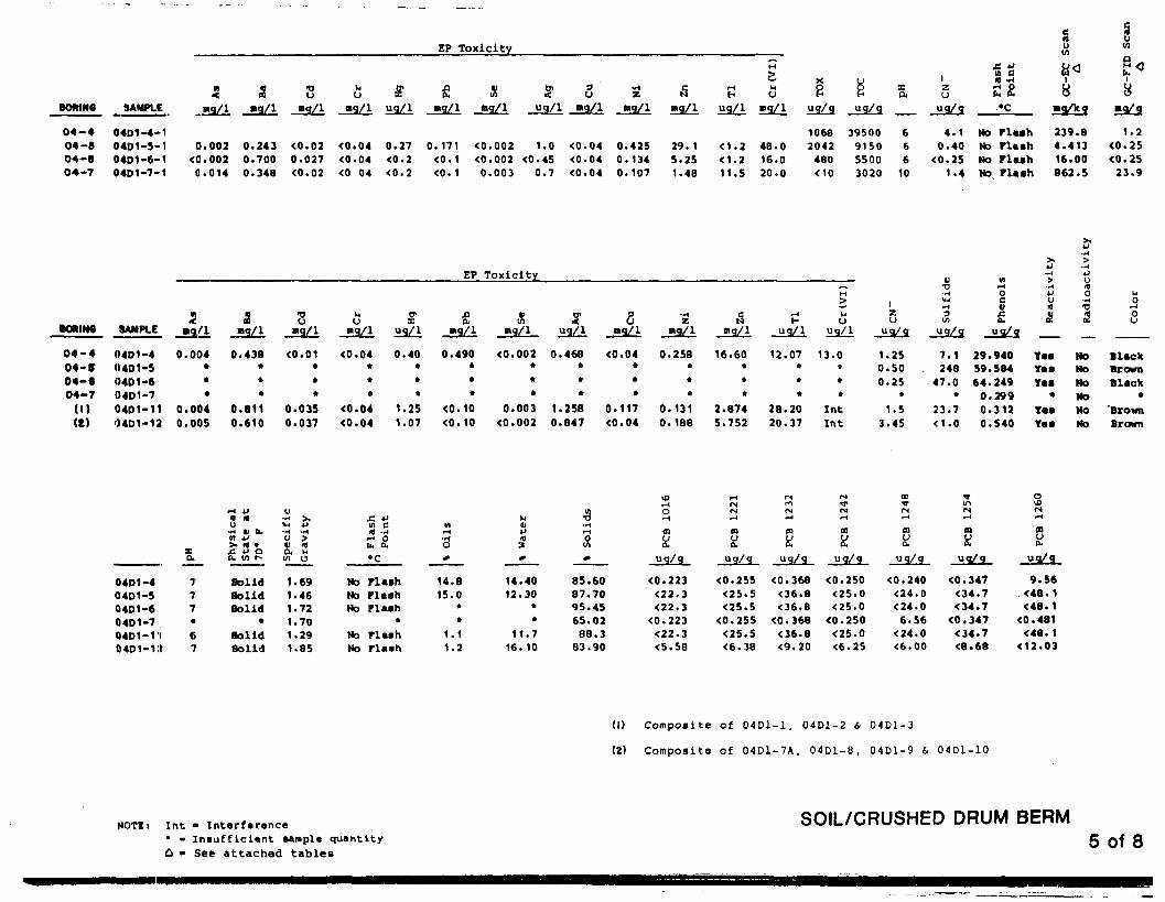
EP Toxicity 0)in
s LIU
BOWNO SAMPLE •g/l »q/i04-4 0401-4-104-5 04D1-5-104-6 04D1-6-104-7 04D1-7-1
0.002<0.0020.014
0.2430.7000.348
<0.020.027<0.02
<0.04<0.04<0 04
$ & xuq/1 aq/l mq/l
3ug/1 ng/1 «g/l »q/l
H oug/i »qA
0.27<0.2<0.2
0.171
<0. 1
<0.002 1.0<0.002 <0.450.003 0.7
<0.04<0.04<0.04
0.4250.1340.107
29. 1
5.251.4B 11.5
48.016.020.0
1068
2042480
39500915055003020
666
10
n c(0 ~HX Uo p sp fi o,
ug/g ug/g ug/q .*CU
4.1 No0.40 No Plash
<0.25 No Plash1.4 No Plash
i iu yo o
»9/k9 »9/9
239.84.41316.00862.5
1.2<0.2S<0.25
23.9
EP Toxicity
SAMPLE «g/I5 XI
On•g/l mq/l uq/l mq/1 uq/i
2U2 N h> U
•q/1 HI g/l ug/1 uq/1 ug/q ug/q ug/q
>.4>
U
I
04-404- •04-«04-7
(1)(C)
0401-404D1-504D1-604D1-704D1-119401-12
0.004•••
0.0040.005
0.438
*••
0.8110.610
<0.01•t•
0.0350.037
<0.04
**•
<0.04<0.04
0.40»
••
1.251.07
0.490
*•
*<0.10<0.10
<0.002 0.468• •
* •* t
0.003 1.258<0.002 0.847
<0.04•••
0.117<0.04
0.258
**•
0.1310.188
16.60••
*2.8745.752
12.07 13.0• •
• *• »
28.20 Int20.37 Int
5
1.250.500.25
•1.5
3.45
7.1248
47.0•
23.7<1 .0
29.94059.58464.2490.2990.3120.540
YasYasYas
•YasYas
NoNoNoMoNoNo
BlackBrownBlack
•'BrownBrown
Xa.
*H 4J1 »u
•H tl U.« v>• a •e. w oQ. V) r~
u•H >,
OVa
0401-404D1-S0401-604D1-704D1-VI0401-i:t
777«r
67
SolidSolidSolid
•SolidSolid
1.691.461.721.701.291.85
£ 4Jvi c-« ou. o.
•3
No PlashNo PlashNo Flash
*No FlashNo Flash
1.11.2
$
14.4012.30
11.7
16.10
85.6087.7095.4565.0288.3
83.90
paX
s(N
ug/g ug/g ug/g ug/q uq/q uq/9
<0.25S<25.5<25.5
<0.255<2S.S<6.38
<0.368<36.8<36.8
<0.368<36.8<9.20
<0.250<2S.O<25.0
<0.2SO<25.0<6.2S
<0.240<24.0<24.0
6.56
<24.0<6.00
<0.347<34.7<34.7
<0.347<34.7<8.68
9.56
<48.1<48.1
<0.481<48.1
<12.03
(1) Composite of 04D1-1, 04D1-2 & 04D1-3
(2) Composite of 0 4 D 1 - 7 A , 04D1-8, 04D1-9 & 04D1-10
NOTEt Int • Intarfarence• - I n s u f f L c l a n t sampla quantity
A • See attached tables
SOIL/CRUSHED DRUM BERM5 of 8

EP Toxlclty£
PORIN8
06-I
OS-I
OB-I
OB-I
(I)
8AMM.E
0501-1OSD2-I05O2-.705D3-105SS-&
2.JsaZl0.003
<<D.002<0.002<0.002
0.005
&«q/l
<0.040.5180.5470.8760.104
•oo•q/1
<0.01<0.02<0.02<0.02<0.01
Mumq/1
0.193<0.04<0.04<0.04<0.04
D<X
uq/1
<0.2
<0.2
<0.2
6.910.22
Smg/l
1.47
0.1180.208
<0.10.714
«Hiq/1
<0.002<0.002<0.0020.009
<0.002
Suq/l
<0.02<0.45
0.45
15.0<0.45
3mq/1
0.279<0.04<0.040.088<0.04
•H•K
mg/l
0.09
<0.04<0.040.0890.049
Smg/l
4.42
0.023<0.020.6380.835
f-4H
ug/1
12.3
4.2<1 .22.2
6.25
M
MU
ug/1
20261910
8.0
z<•> _ . .
« 5a 8fH u
& £
>•HUUa& R
adio
ac
uq/q ug/g _ug/g
<0.2S1.55
<0.251.55
0.65
<1 3.80
<1 0.187<1 0.91
<1 4.76
* 4.445
NoYes
NoYesYes
NoNONONONo
uO
rH
5
BlackGrayGray
Ok BrrDk Brt
OSDt-1
05D2-1
0502-20503-105SS--6-
2131312*
-o a
SolidSolidSolidSolidSolid
O
w*
0.991.411.421.66
*
C. ug c-< oin n,
Ho Maah
No PlashNo FlashNo Flash
26.1<0.5< O . S0.7640.4
83.1066.9782. 1077.9084. 10
\DrHOfH
m«
uq/g
<0.405<0.081<0.081<O.QB1<0.223
.H<NMfH
nU
uq/g
<0.625<0.125<0. 125<0.125<0.255
(MrnIN»H
aK
ug/q
<0.86<0.172<0.172<0.172<0.368
fM*rPMr-4
ffl
id
ug/g
6.75
<0.132<0.1320.800
<0.250
o>**IN-1
o!ug/g
<0.66<0.132<0.132<0.132<0.240
<»mnMaK
uq/q
<0.96<0.192<0. 192<0.192<0.347
oVOM.H
0)oo.
uq/q
2.90
<0.185<0.18S0.32713.6
(I) Soil Composite of 5 Su r f ace Soil Pointsin LOG #5 - C o n t a m i n a t e d Soil A r e a .
HOTKt int - Interference'' • Insufficient sample quantity
CONTAMINATED SOIL AREA6 of £

BOftINQ
(1)0«-lOS -206-10»-20«-»0«-loe-2
SAMPLI:
06-2-990601- 1060 1-20602-10602-2 .0602-40603-106D3-S
3.mq/l
<0.002<0.002<0.002<0.0020.0030.004
<0.002<0.002
2Pq/l
0.1480.6500.5660.3390.3700.603
1.940.277
smq/l
<0.020.1970.0220.027<0.02<0.02<0.02<0.02
uu
<0.04<0.04<0.04<0.04<0.04<0.040.4910.120
uq/1
<0.20.51<0.2<0.2<0.2<0.2<0.2<0.2
m ^ l
0.3410.6230.993
<0. 10.3550.6310.720
<0.002<0.002<0.002<0.002<0.002<0.002<0.002<0.002
u ? l
0.8<0.45<0.45<0.4S<0.45
0.50.70.5
u
<0.040.95
<0.040.078<0.04<0.04<0.04<0.04
• H
mq/l
<0.040.6110.3766.43
0.9960.703<0.040.560
0.07610.49.847.6113.624.8
0.04223.1
M
H Uuq/1 ug/1
<1.2 10<1.2 3<1 .2 5<1.2 10< 1 . 2 28<1.2 10<1.2 37<1 .2 80
I
U
<0.2S0.8
0.7522.00<0.25
0.251.76.8
V VI i»TJ )•* »H
£ g tJy c, *
uq/q ug/g
<1 4.53 No<1 0.66 No<1 15.88 Y«a<1 49.08 Y«S<1 101.79 Y«S<1 67.35 Y.a<1 5.05 Y»s
<1.0 100.92 Yes
Rid
ioac
NoNoNoNONoNoNONo
Co
lor
WhiteMd BrnDk BrnDk Brn
BlackBlackBlack
. Dk Brn
06-2-9'J0601-10601-20602-10602-20602-40603- 106D3-2
Xa
676
1277
137
>~t +J Cat aU *•3 u '[>. <o • <£ « O Co, <o r- v
SolidSolidSolidSolidSolidSolidSolidSolid
Gra
vit
y
.70
.40
.40
.36
.54
.541.291.44
w ca <HM OU, Q,
•c
No FlashNo FlashNo Flash
29»CNo Flash
48»C35»C29«C
in•HO
<0.5<0.59.3
1627.728.41.5257.7
M914Jfl3
f
0.0012.9015.3011.005.68
12.9015.1013.00
in•o• H1-4
&
f
100.0087. 1084.7089.0094.3287.1084.9087.00
0
m
—
<0.081<0.40S<0.405<0.405<0.405<0.405<0.405
r*4t-4
COuCu
—
3.24<0.625<0.625<0.625<0.625<0.625<0.625
<N
mk!
ug/g
^
<0 .172<0.86<0.86<0.86<0.86<0.86<0.86
m
ug/g
^
1.2820.224.157.043.22.5545.4
m
ug/g_
<0. 132<0.66<0.66<0.66<0.66<0.66<0.66
fN
OQ
ug/g—
<0.192<0.96<0.96<0.96<0.96<0.96<0.96
(Nr-4
ffiOo.
uq/q
»
1.535.0511.311.88.25
<0.92510.1
(I) Soil Bank (Silica S a n d ) Processed 0 LOC 06-2
NOTIi Int • Intsrfurence• • I n s u f f l c i a n t sampla quantity
FILLED IN AREA
7 of 8

EP Toxicity •sHIjra.
u<0
8.
(I)(8)
OT-I
0701-30702-30703-1
<0.0020.0030.002
O.S720.7690.547
<0.02<0.02<0.02
<0.04<0.04<0.04
<0.2<0.2<0.2
0.4690.391
<0.002<0.002C0.002
o.s0.5
<0.45
<0.04 0.124<0.04 0.598<0.04 0.637
3.2511.515.7
202828
uq/q uq/q0u
1.652.7
14.65.066.4
0.4585.4092.64
Ye«Ye«
No BrownHo Dk BrnNo Dk Brn
07D1-307D2-307D3-1
S.676
Ph
ysi
cal
Sta
te
at
70*
F
f ty
Spe
c
Gra
v
c. u3.5ZS,•c
Solid 1.58Solid 1.74Solid 1.59
Ho Flash27'C
25.5»C
1.1416.029.0
ter
10•-*o
13.9014.0014. 10
uq/q<0.081<0.405<0.405
COa CQa nuo.
ug/g ug/q uq/q ug/q ug/g
3.90 <0.172<0.625 <0.86<0.625 <0.86
1.40 <0.132 <0.192 2.238.60 <0.66 <0.96 4.309.30 <0.66 <0.96 2.97
(I) Composite of LOG 07-1 (Dl) (0-3.5')07-2 (Dl) (0-4')
(Z) Composite of LOC 07-1 (D2) (3.5-10')07-2 (D2) (4-8.5')
NOTEi Int • Interference* - Insufficient sample quantity
SEEPAGE AREA8 of 8

*>./)Cli«nt 3015
ANALYTICAL KCSULTC
Data
Instrument:5985 #1
sitelab no.frn no.analysis dateanalysis timeanalyst initials
IV •en>l«in 100rv Acrylonitrilc looIV b«nc«n« 10IV,V broaofoz* 20IV oarbon t«tr« chloride m
TV eMoroben»«n« 10BV chlorodihronoaithJU* lo9V chloro»th*ne 3010V 2-chloro«thylvinyl «ther ^Q11V chloroform 1012V dichlorobroaoBethainc 901 3V.4V ,1-dichloroe thane 20.5V ,2-dichloroethane 20.6V ,1-dichloroethylene 20.TV ,2-dichloropropane 20•V , 3-dichloropropylene 109V ethylbenrene 10
•0V aw thy 1 breed de ' 30IV Mthyl chloride 102V »ethylene chloride , IQ3V 1,1,2,2-tetrachloroethane 104V tetrachloroetbylene 105V toluene 106V 1,2-trftnc-dichloroethylene 20TV l,l,l-trichloroeth«ne 208V l,1.2-trichloro«th*n« 209V trichloro«thyl«ne 103V trichlorofluoronwth*n« 50IV vinyl chloride 30
Volume purged
Spike level
4«-l,2-dichloroe thane
de-tolueneP-BFB
I
////////
////////
////////
ACROUtACKYLOC6H6
CHBR3CCL4CLC6H5DBRCIXC2H5CL2CLEVECHCL3BRDCIJ4
11DCLE12DCLE11DCE12DCLP13DCPETC6H5CH3BRCH3CLCH2CL2TCLEATCLEEMEC6H5T12DCE111TCE112TCETRCLECCL3F •C2H3CL
01S-581580
297339/23ib:4U
JDH
33
68
18
122
OlBL-681581
297349/23lb:4b
JDH
31
3093
98
1351
56166
215
270470
293
-0.5 o 0.5 gw/Ttr w/TG
VOA SURROGATES
02-1-9981582
297249/21
:45
BAK
3
1
2
38
1473
01S-581583
297279/2114:30
BAK
1800
5400013000
84800
31800
01S-681584
279319/2312 : 3"b'
JW
2000
10000
40300
340023700
6000
5000
LabBlank"
297309/23lU:lb
JW
2
1539
2
LabBlank297209/21/.:isuBAK
5
5 ml 0.005 g O .OObg S ml £ nuNo TG w/TG w/TG w/TG No TG
TG=tetraglyme
50 Units ug/1 in water
12DCD4
MEC5D8PBFB
15
4036
41
4159
45
4945
27
4837
J
47
3749
1
64
3358
46
4443
1 1
NOTE: All results reported in ug/l_21 'unless otherwise notedWhere no value appears, the compound was not detected.

ANALYTICAL
./gli«at 3015 Pat*
(VGA) Instrument: 5985 #1
_of
sitelab no.frn no.analysis dateanalysis timeanalyst initials
IV •croltia 100rv acxylonitrll* 100tv b*nc«a« 10IV,V feroMofoni 20iV <wrbon t«tr«chlorl4« -^nrv chlorob«nMn« 10rv c&lorodlbroaoMt*t«A* 10IV chloro*thkn« 300V 2-chloro«thylvlnyl «th«r 20
11V chloroform 101 TV dichlorobroaK30Kth«nt 20IJV14V l,l-dichloro«th»n« 20ISV l,2-dichloro»thAn« 20t6V l,l-dichloro*thyl«n« 2017V l,2-dichloroprop*n« 20IfV 2,3~dichloroprppyl«n« 10i9V «thylb«ntene 10tOV vethyl broaid> ' 30tiv methyl chloride 10>2V methylene chloride . JQ!3V l,1.2,2-tetr«chloroeth*ne 10>4V tctr«chloroetbyl«ne 10•SV toluene ^0*6V l,2-tr*n«-dichloroethylene 20TV 1.1,1-trichloroe thane 206V l,1.2-trichloroeth»ne 20*V trichloroethylene 100V txichlorofluoromethtne 50IV vinyl chloride 30
////////
////////
////////
ACROLN
ACRYLO
C6H6
£HEa2_OCL4CLC6H5
DBRCLMC2H5CL2CLEVECHCL3BRDCLM
11DCLE12DCLE11DCE12DCLP13DCPETC6H5CH3BRCH3CLCH2CL2TCLEATCLEEMEC6H5T12DCE111TCE112TCETRCLECCL3F •C2H3CL
LabBlank
297269/21JJ:4U
BAK
7 l
120
25
>4b«
385
-
•
5 mis
VGA SURROGATES
Spike level 50 Units ug/1
d^-l , 2-dichloroe thanede-tolueneP-BFB
12DCD4
MEC5D8PBFB
63
4141
—
i
•
.
— • • ""
__^.
NOTE: All" results reported in ug/i or ug/£gi«,gc otherwise noted.va q not detected.
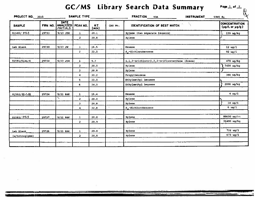
GC/MS Library Search Data SummaryPROJECT NO. 3015 SAMPLE TYPE FRACTION VGA INSTRUMENT 5985 fl
SAMPLE
81i>80/ 015-5
Lab Blank
81581/01BL-6
81582/02-1-99
81583/ 01S-5
Lab Blank.
(w/tetraglyrae )
FRN NO.
29733
29730
29734
29724
29727
29726
DATEANALYZED/ INITIALS
9/23 JDH
9/23 JW
9/23 JDH
9/21 BAK\
9/21 BAK
9/21 BAK
PEAK NO.
l2
1
2
1
2
3
4
5
6
1
2
3
4
1
2
1
2
RT(mln)
28.1
28.8
16.5
33.0
9.7
28.0
28.8
30.2
33.0
34.0
16.4
28.0
28.8
32.8
28.0
28.9
28.0
28.8
CAS NO.
•
IDENTIFICATION OF BEST MATCH
Xylene (two separate isomers)
Xylene
Hexane
dA-dichlorobenzene
1,1, 2-trichloro-l , 2 , 2-trif luoroethane (f reon)
Xylene
Xylene
Propylbenzene
Ethylmethyl benzene
Ethylmethyl benzene
Hexane
Xylene
Xylene
d^-dichlorobenzene
Xylene
Xylene
Xylene
Xylene
CONCENTRATION(jig/L or jig/g )
\ 139 ug/kg;12 ug/1
92 ug/1
470 ug/kg
'I 7450 ug/kg
J
380 ugAg
•^ 2090 ugAg
4 ug/1
f 14 ug/1
6 ug/1
88600 ug/kT
31400 ug/kg
732 ug/1
673 ug/1

GC/MS Library Search Data SummaryPROJECT NO. SAMPLE TYPE FRACTION VOA INSTRUMENT 5985 ffl
SAMPLE
81584/ G1S-I)
FRN NO.
29731
DATEANALYZED/ INITIALS
9/23 JW
PEAK NO.
12
3
4
5
6
7
8
9
(mln)
5.0
5.9
11.6
16.6
28.1
28.9
30.3
33.1
34.2
CAS Mo. IDENTIFICATION OF BEST MATCH
Acetone
Carbon disulflde
1,4-dioxane
Hexane
Xylene
Xylene
ProDvl benzene
Methyl ethylbenzene
Methyl ethvlbenzene
CONCENTRATION(jig/Lor pg/g)
17000 ug/kq
12000 ug/Xg
18000 ugAg
3870 ugAg
\ 59000 ugAgJ
7800 ugAg
9170 ugAg
9810 uciAg

ANALYTICAL Instrument: _5996_
Project •D./ni«Dt_ 3015 Waters
site ~lab no.frn no.analysis dateanalysis timeanalyst initials
IB acenaphth«ne ANAPNE21 «c«naphthyltn« ANAPXL3B •nthrae«n«* ANTKC4B bentidiM BENZIDSB b*n*o(«)anthrae«n«« HAANTK6B b«n*o7*Tpyr*m 6APYK7B J.4-b*ntozluoranthtr** J4BTAN•B b«n*o(ghi)i»ryltM BRHTPY
////////////////////////
ISO100100700100600200300
9B b*nco(k)fluor»nth«M* BKFANT 20010B bit(2-ehl6ro«thoxy)MthAM B^CEXM^CTO11B bit (2-cMoro«thyl)tth«r B2CLEE ISO12B bit (2>cMoroi»opropyl)«th«rB2CIP£i501JB bi«(2-»thylh«j(yl)phthal«t« B2EHP 15014B 4-bro»oph«nyl phcnyl otter 4BRPPE350
15B butyl benzyl phth«l*teBBZP16B 2-chloronaphth«lene 2CNAP
1505nn
17B 4-chlorophenyl phcnyl ether 4CLPPEi5QL6B chrysene4 (see SB) CHRY19B dlbenzo(a,h) anthracene DBAHA20B 1,2-dichlorobenzene 12DCLB21B 1,3-dichlorobenzene 13DCLB22B 1,4-dichlorobenzene 14DCLB23B 3,3'-dichlorobenzidine 33CL2B24B die thy 1 phthalate DEP25B dimethyl phthalate Dj^p26B di-n-butyl phthalate DNBP27B 2,4-dinitrotoluene 24DNT28B 2,6-dinitrotoluene 2iDNT29B di-n-octyl phthalate DNnP30B 1,2-diphenylhydrazine 12DPH
(as azobenzene)31B fluoranthene TANT32B fluorene P1.RENE33B hexachlorobenzene CL6BZ34 B hexachlorobutadiene HC3D
100Tin
L 200200?nn?nn150200100350finnion150
100i sn350BOO
3SB hexaehlorocyclopentadiene CL6CP BOO36B hexachloroethane CL6ET37B indeno(l,2,3-cd)pyrenejQppY£36B isophorone ISOPHR39B naphthalene NAP40B nitrobenzene JIB41B N-nitrosodimethylamineNDMA42B N-nitrosodi-n-propylamine NPNP43B N-nitrosodiphenylamineNNDPA44B phenanthrene* (see 3B)pHftNTR4 5B pyrene PVR46B 1,2,4-trichlorobenzene j23i>cB
soo300100inn?no150
A 200350100TOOinn
01BL-681581A348711/801 :12
LMC
60
13
6
14
4634124
59RO113
24
9
02-1-9981582A345611/122:24
LMC
20
7]f,
5
BNA SURROGATES
MB4067A345811/200:11
LMC
2?q
1
6
I
.
Spike level 100 or 200 Units ua/i
ds-nitrobenzene KBD52 f luorobiphenyl TIOBPdB-naphthaiene NAPD8
ND
182im
60
45
41
4175
NOTE: All results reported in "9/1 unless otherwise noted.Where no value appears, the compound was not detected.

JMULYTICAL SULIS Instrument: 5996
rro>rt »o./tlt»Pt 3015 Waters
sitelab no.frn no.analysis dateanalysis timeanalyst initials
ACID COMPOUNDS
LA l-cMoroph«nol 2CLPtA 2,4-dlcMorophtnol 24DCLPIA J,4-di»«thylph«nol 24DMP1-IA 4,6-diMtxe-o-crtBol 46DN2CA 2,4-diniU-ophfnol 24DNP
iA 2-nltrophtnol 2NP7A 4-nitroph«nol 4NP•A p-chloro-»-ert»ol 4CL3C9A p«nt«chloroph*nol PCP
OA fhtnol PHENOI11A 2,4.t-trichloroph«nol 246TCF
////////////////////////
200300400700700400350400350150800
01BL-681581A348711/8Ul:l^
LMC
^bJ
1430
02-1-9981582A345611/1li: 24
LMC
77
ACID SUPJIOGATES
MB4067Ai456
11/2UU : il
LMC
Spike level 100 or 200 Units ug/l
2-F-phenol 2FPphenol-d6 PHENDtoenta-F-phenol err
spike level
PESTICIDES
IP *ldrin ALDRN2P o-BHC ABHC3P C-BHC BBHC4F Y-BHC f l indane) LINSP 6-BHC DBHC6P ehlordane fl.DAN7p 4. 4 '-DDT PPDDT6P 4, 4 '-DDE PPDDE9P 4, 4 '-ODD PPDDD10P dieldrin nr.nRNIIP o-«ndosulfan AFN^T.F12P 8-«ndo»ulf»n BFN^T.F13P cndotulfan fulfat* ESFSO414P «ndrin ENDRN15P cndrin aldehyde ENDALD16P hejstachlor HPCL17F heptmchlor cpoxide HPCI E18P PCB-1242 PCB24219P PCB-1254 PPB2S420P fCB-1221 PCR22121P FCB-1232 prn?T722P PCB-1248 T>rR->HR23P PCB-I260 T>rT.t>An24P PCB-1016 prnn i f i2SP toxaphene TYPHPK
104133203200
1000100010001000100Q
?*> nnn100010001000i nnr50005000500C200C500Ci nori n n r
i n ,oori o nnri n nnri n nnri n^nri n nn ri n , n n r«in nnr
302426100
32
27Ib100
^
NOTE: All results reported in uo/i unless otherwise noted.Where no value appears, the compound was not detected.

MULTTXCJU. uLTS (BNA) Instrument: 5996
rroj«ct 3015 soils
sitelab no.frn no.analysis dateanalysis timeanalyst initials
IB acen«pt)th«nt ANAPNE2* «c«naphthyltne ANAPYL3B *nthr«c«n«« ANTRC4B benxidir* BENZ1DSB fe«n*oU)*nthr«c«n«* dAArJTRit btnu>U)pyr«n* BAFYK7» J,4-btn«ofluoranth«i*» JJBTA'NU benuXghDptryl.!* pfiHTPY
////////////////////////_
150100100700100600200300
9B b«n«o(k)fluoranthtn«« BKFANT 20010B bit(2-cMoro«thoxy)sttth*n* B2CEXM20011B bis(2-efclorotthyl)»th«rB2CLEE 15012B bis (2-chloroisopropyl)«tJ»«rB2CIPEl5013B bis(2-«thylh«jcyl)pnthalat« B2EHP 15014B 4-broaophtnyl phenyl «th«r 4BRPPE350
15B butyl benzyl phth«l«t«BBZP16B 2-chloronaphthalene 2CNAP
1502nn
17B 4-chlorophenyl phenyl ether 4CLPPE15DIBB chrysene« (see SB) CHRY19B dibenzo(».h)»nthr«c«neDBAHAJOB 1,2-dichlorobenzene 12DCLB21B 1,3-dichlorobenzene HDCLB22B i,4-dichlorobenzene 14DCLB23B 3,3'-dichlorobenzidine 33CL2B24B diethyl phthalate DEP25B dimethyl phthalate DMP26B di-n-butyl phthalate DNBP27B 2,4-dinitrotoluene 24DNT2BB 2,6-dinitrotoluene 26DNT29B di-n-octyl phthalate DNOP30B 1,2-diphenylhydrazine 12DPH
(as azobenzene)31B fluoranthene FANT32B fluorene FI,T?FNK33B hexachlorobenz«ne CI^GBZ34B hexachlorobutadiene HCBD
1003102002002 noTonISO200100350BOOion150
ionTin350BOO
35B hexachlorocyclopentadiene CL6CP BOO36B hexachloroe thane CL6ET37B indeno(1.2,3-cd)pyrenejcDPYR38B isophorone ISOPHR_39B naphthalene NAP40B nitrobenzene NB41B N-nitrosodi»ethylamin«NDMA42E N-nitrosodi-n-propylanine NPMP43B N-nitrosodiphenylaJnineNNDPA44B phenanthrene* (see 3B)pHANTR4 SB pyrene PYR46B 1.2,4-trichlorobenzenei2iTCR
Dilution:
Spike level
ds-nitrobenzene HBD52 f luorobiphenyl F10BPde-naphtnalene NAPD8
500300100ion2nn150
ft 200350100ion?nn
01L-581560A348811/8
02:05LMC
253
57
24
36
182
11
11820
01S-581583A3 46011/201:58LMC
115
32
4
17
2
8?13
159
21
370210
6656
1:10BNA SURROGATES
01S-681584A346111/202:51LMC
119
17
17
2
2137
157
35
229220
927
61
MB4064A3 46;11/203:45LMC
21
116
200 Units ug/g
240326276229
150226187166
196375286199
144201144108
NOTE: All results reported in ug/gWhere no value appears, the compound was not detected.
unless othervise noted.
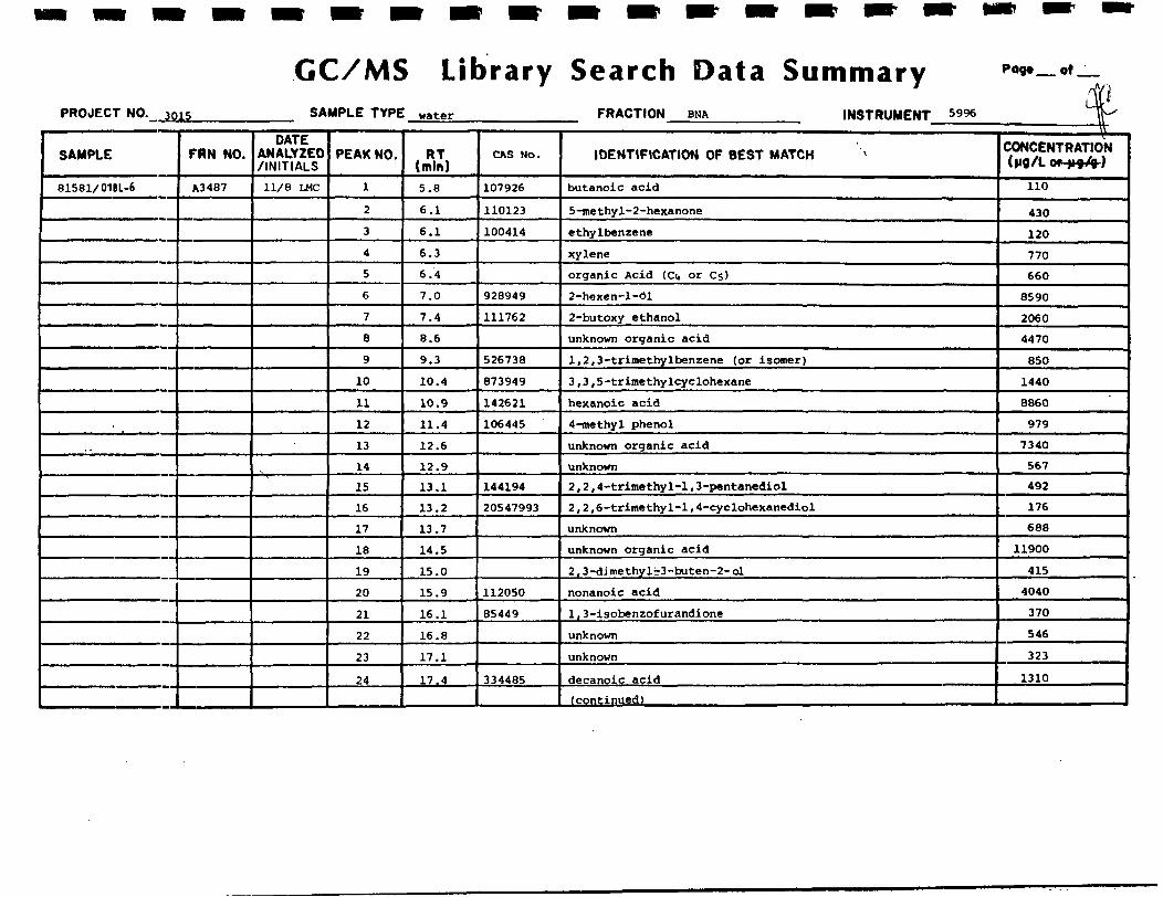
GC/MS Library Search Data Summary Pog« of
PROJECT NO. J015 SAMPLE TYPE water FRACTION BNA INSTRUMENT 5996
SAMPLE
81581/01BL-6
FRN NO.
A3487
DATEANALYZED/INITIALS
11/8 LMC
PEAK NO.
1
2
3
4
5
6
7
8
9
10
11
12
13
14
15
16
17
18
19
20
21
22
23
24
RT(m!n)
5.8
6.1
6.1
6.3
6.4
7.0
7.4
8.6
9.3
10.4
10.9
11.4
12.6
12.9
13.1
13.2
13.7
14.5
15.0
15.9
16.1
16.8
17.1
17.4
CAS Mo.
107926
110123
100414
928949
111762
526738
873949
142621
106445
144194
20547993
L112050
85449
334485
IDENTIFICATION OF BEST MATCH
butanoic acid
5-methyl-2-hexanone
ethylbenzene
xylene
organic Acid (Ci» or Cs)
2-hexen-l-ol
2-butoxy ethanol
unknown organic acid
1,2,3-trimethylbenzene (or isomer)
3 ,3 ,5-trimethylcyclohexane
hexanoic acid
4-methyl phenol
unknown organic acid
unknown
2,2, 4-trimethyl-l , 3-pentanediol
2 , 2 ,6-trimethyl-l , 4-cyclohexanediol
unknown
unknown organic acid
2 , 3-dimethylb3-buten-2- ol
nonanoic acid
1 , 3-isobenzof urandione
unknown
unknown
decanoic acid(continued) ___
CONCENTRATION(jlfl/L ot-p«4-)
110
430
120
770
660
8590
2060
4470
850
1440
8860
979
7340
567
492
176
688
11900
415
4040
370
546
323
1310

GC/MS Library Search Data Summary P0fl« Of
PROJECT NO. 3015 SAMPLE TYPE water FRACTION BNA INSTRUMENT 5996
SAMPLE
81581/01BL-6
(Cont.)
FRN NO.DATE
ANALYZED/INITIALS
PEAK NO.
25
26
27
28
29
30
31
32
33
34
RT(mln)
18.5
19.4
20.5
22.1
23.2
24.9
25.8
27.5
28.2
30.7
CAS No.
-
-
-
544638
629630
57103
629798
57114
124265
IDENTIFICATION OF BEST MATCH
unknown
unknown
unknown organic acid (dodecanoic (Ci>)
unknown
tetradecanoic (Cm) acid :
tetradecancnitrile
hexadecanoic (Ci ) acid
hexadecaneni tri le
octadecanoic ( C i f ) acid
octadecanamide
CONCENTRATION
1770
3540
1370
1810
447
435
1190
860
369

GC/MS Library Search Data SummaryPROJECT NO. 3015 SAMPLE TYPE water FRACTION BNA INSTRUMENT
5996
SAMPLE
81582/02-1-99
MB 4067
FRN NO.
A3456
A3458
DATEANALYZED/ INITIALS
11-1-85/U
'
11-1-85 L
PEAK NO.
; 1
2
3
4
5
6
7
8
9
10
11
12
13
14
15
1C 1
2
3
4
(mln)6.6
7.2
13.6
16.2
16.4
17.0
17.4
18.9
20.6
21.6
23.03
23.2
26.9
31.2
32.0
16.1
17.0
17.4
31.2
CAS No.
— -65850
92313
85449
74367332
74367343
956027
939480
17904277
123795
10546700
92513
74367332
74367343
123795
IDENTIFICATION OF BEST MATCH
Xylene (1,4, 1,2 or 1,3)
Xylene - unknown
benzole acid
1,1-bicyclohexyl1 , 3-isobenzof urandione2-methyl-2 , 2 , -dlmethyl-1- ( 2-hydroxy-l-methyl )
ethyl propyl ester of propanoic acid2-methyl-3-hydroxy-2,4,4-trimethyl pentyl ester of
propanoic acid
2-hydroxy benzoic acid hydrazide
unknown
unknown
unknownbenzoic acid, 1 -methyl ethyl ester1-cyclohexene-l-carboxylic acid, 4-(lc5-dimethyl-
3-oxyohexyl)-, methyl esterdioctyl adipate
N-propyl benzamide
1,1-bicyclohexyl
see (t 6 above
see ft 7 above
dioctyl adipate
CONCENTRATION(jtf/b-erpg/g)
2
2
6
3
7
9
e3
8
28
11
6
2374
25
3
7
7
438

JUULYTlCAi
*ro>et 3015 Soils
tULTS
_»at»
Instrument: 5996
Site :
lab no.frn no.analysis dateanalysis timeanalyst initials
ACID COMPOUNDS
LA »-eMoroph«nol 2CLPtA 2,4-diehlorophtnol 24DCLF1A 2,4-di»ethylphtnol 24DMPh
A 4,*-dinitro-o-er««ol 46DN2CA 2.4-dinitrophtnol 24DNPA >nltroph«nol 2NP'A 4-nitrophtnol 4NP
tA p-ehle>ro-»-cr««ol 4CL3CA p*nt*cMoroph*nol POPOA phenol PHENOI1A J,4,i-t.ricMorophenol 246TCJ
Dilution
Spike level
2-F-phenol 2FPphenol-d6 PHEN1Moenta-F-phenol PTP
PESTICIDES
IP aldrin ALDRN2P o-BHC ABHC3P 6-BHC BBHC<F f-BHC ( l indane) LIN5P 6-BHC DBHC6P chlordane CI.nAN7p 4, 4 '-DDT PPDDTep 4. 4 --DDE PPnnr.9P 4 .4- -DDD PPDDn10P dieldrin DT.nRNIIP o-*ndoculf&n AKN^T.r12P fl-«ndosulf«n BENSLF13P «ndo»ulf«n «ulf«te ESFSO414P tndrin ENDRNISP cndrin aldehyde ENDAT.n16P heptachlor HPPT.17p heptachlor epoxide HPPT F18P PCB-1242 PPR54?19P PCB-12S4 PPB7S420P PCB-1221 pm??121P PCB-1232 pru^"»722P PCB-124B prTOJB23P PCB-J260 prB-)<;ft24P PCB-1016 prnrnfi2SP tsxaphene TYPHFN
////////////////////////_
200300400700700400350400350156800
01L-581580
11/802:05LMC
IB
01S-561583
11/201:58LMC
ii j ii ft
Ji
117
ACID SU&i&ATES <^
01S-681584
11/202:51LMC
it)
87
MB4064
11/203:45LMC
i •••u1
1j
I
200 Units ug/g
213254 '172
1000
100010001000100Q
f*\ , nnp10051000
166156 "
97
loonj1 ftofl'soon5onr500C200C50orioori n n r
i n , f t n rI0 ,oori o r o n ri o r n o f ji n ^ o n Hin nnrii n r o o r j^ n ^ n n f j
!
192219216
1
171' 162
76
|
I
"
1 •
i
1 J
NOTE: All results reported in uq/q unless otherwise noted.Where no value appears, the compound was not detected.

CC/MS library Search Data Summarysoil
I SAMPLE ( I MT£ I IFftN MO. /ANAUrZCDJ PEAK MO. I
f/HW'TiALS / /PEAK MO. I . RT CAS Mo. OF BEST MATCH {CONCENTRATION
3."
5. *
/ i /1 <7
8
9
10
11
12
13
14
15
16
17
18
19
20
21
22
23
2425
-f. 4
19.7
19.0
19.1
20.4
20.6
21.4
21.7
22.1
22.2
23.2
22.5
23.6
24.7
24.9
25.0
25.9
26.1
21.5
28.228.4
" — "VX.* [ :rurMnc-i.r *d.a ^ jc
II2379 | orwJ'-canoic acid fCj j ) | JJ
2244077 jundecanenltrile | 61
1560958 | 2-methyltetradecane j 24
143077
55045084
638539
-
544638
629630
57103
629629
57114
dodecanoic acid (da)
2-methyl-6-propyl-dodecane
hydrocarbon
tridecanoic acid (013)
hydrocarbon
hydrocarbon
tetradecanoic acid (C1H)
phenanthrene + hydrocarbon
hydrocarbon
unknown amide
hydrocarbon
tetradecanenitrile
hexadecanoic acid
pentadecane
hexadecanenitrile or heptadecanenitrile
octadecanoic acid
unknown amide
455
36
16
23
195
35
229
180
39
59
61
366
369
45
799
23597

GC/MS Library Search Data Summary Pog« of
PROJECT NO. 3015 SAMPLE TYPE Soil FRACTION BNA INSTRUMENT 5996
SAMPLE
81580 (Cent.)
FRN NO.DATE
ANALYZED/INITIALS
"
PEAK NO.
26
27
28
RT(min)30.7
35.06
35.8
CAS No.
124265
3722529
IDENTIFICATION OF BEST MATCH
Octadecanamide
Unknown
9-H-Xanthen-9-one , 3-tnethoxy
CONCENTRATION
179
148
68

GC/MS Library Search Data SummaryPROJECT NO. 3015 SAMPLE TYPE Soil FRACTION UNA INSTRUMENT
SAMPLE
81583/01S-5
FRN NO.
A3 460
DATEANALYZED/INITIALS
11/2 LMC
PEAK NO.
1
2
3
4
5
6
7
8
9
10
11
12
13
14
15
16
17
18
19
20
21
22
23
24
RT(mln)
17.8
18.0
18.3
18.6
18.8
19.1
19.4
19.5
21.0
21.8
22.2
22.6
22.6
22.9
24.1
25.0
25.3
25.4
26.5
26.5
27.7
27.9
28.8
30.7
CAS No. IDENTIFICATION OF BEST MATCH
Unknown hydrocarbon
Dimethyl naphthalene isomer
Dimethyl naphthalene isomer
Dimethyl naphthlanee isomer
Unknown hydrocarbon
Unknown Alkene
Unknown
Unknown hydrocarbon
Unknown hydrocarbon
Unknown hydrocarbon
Unknown alkene
Unknown hydrocarbon
Unknown hydrocarbon
Methyl - 9H-fluorene
Unknown hydrocarbon
Unknown phthalate
Unknown hydrocarbon
Unknown nitrile
Unknown acid ethyl ester
Unknown hydrocarbon
Unknown hydrocarbon
Unknown nitrile
Unknown alkyne
Unknown alkyne
CONCENTRATION()*i<tr«r>ig/g)
57
34
44
34
25
131
36
73
87
35
52
116
52
33
40
22
48
71
30
33
21
67
25
22

GC/MS Library Search Data SummaryPROJECT NO. 3015 SAMPLE TYPE Soil FRACTION SNA
INSTRUMENT 5996
SAMPLE
81584AI1S-6
FRN NO.
A3461
DATEANALYZED/INITIALS
11/2 LMC
PEAK NO.
i2
3
' 4
5
6
7
B
9
10
11
12
13
14
15
16
17
18
19
20
21
22
23
24
RT(mln)
6.0
-7.9
9.6
11.7
12.0
13.1
14.0
16.0
17.8
18.0
18.3
18.8
19.1
19.4
19.5
20.5
21.1
21,8
22.6
22.7
24.1
25.4
27.6
27.9
CAS No.
*
IDENTIFICATION OF BEST MATCH
No hits
Methyl ethyl benzene
Methyl ethyl benzene
Dimethyl ethyl benzene
Unknown hydrocarbon
Dimethyl ethyl benzene
Unknown hydrocarbon
Unknown hydrocarbon
Unknown hydrocarbon
Dime thy 1 naphthalene
Dimethylnaphthalene
Unknown hydrocarbon
Unknown alkene
Unknown nitrile
Unknown hydrocarbonTrimethyl naphthalene
Unknown hydrocarbon
Unknown hydrocarbon
Unknown hydrocarbon
Unknown hydrocarbon
Unknown hydrocarbon
Unknown nitrile
Unknown alkene
Unknown nitrile
CONCENTRATION
76
28
39
26
28 .
23
22
53
40
24
23
21
34
79
71
32
100
36
119
42
39
77
21
79

GC/MS Library Search Data SummaryPROJECT NO.
SAMPLE
MB 4064
SAMPLE TYPE soil FRACTION BNA INSTRUMENT 5996
f RN NO.
A3 46 2
DATEANALYZED/INITIALS
11/2 LMC
PEAK NO.(mln)5.0
CAS No. IDENTIFICATION OF BEST MATCH
4,4 dimethyl - 2 - pentene
CONCENTRATIONng/g)
176
6.2
6.5
Unknown 1291
Unknown hydrocarbon 67
6.7 Unknown hydrocarbon 116
8.0 Methylethylbenzene 426
24.9 Unknown phthalate 110


m

T.L fcr£ & ~


£ >_toi.e.i**»._«_.v__c , /MAA its Lsfj *<?* cs>


' i j f r j t ftta^E si^'/l li - - - T - " - ' - r - i -
Vtlu a. »VN)j>__AElSj
]._' ' I l li--f--M-4-t-~


, / , \,".•** A+fy7. ./; /((.. •M/sX'. ~i


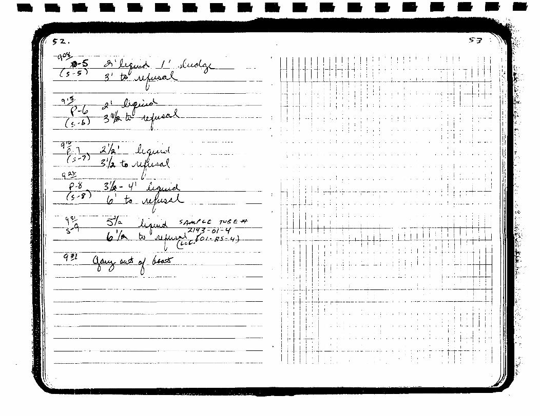
te
'A'* 3 - 01 -'A'* 3 -\J*-*- [Q; -
1 1-i-H
nS :U-444
L-U-• t - t -
. I i.' ' I '
• I i'"i r t~
fe**.-
ft*

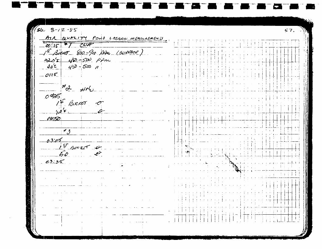


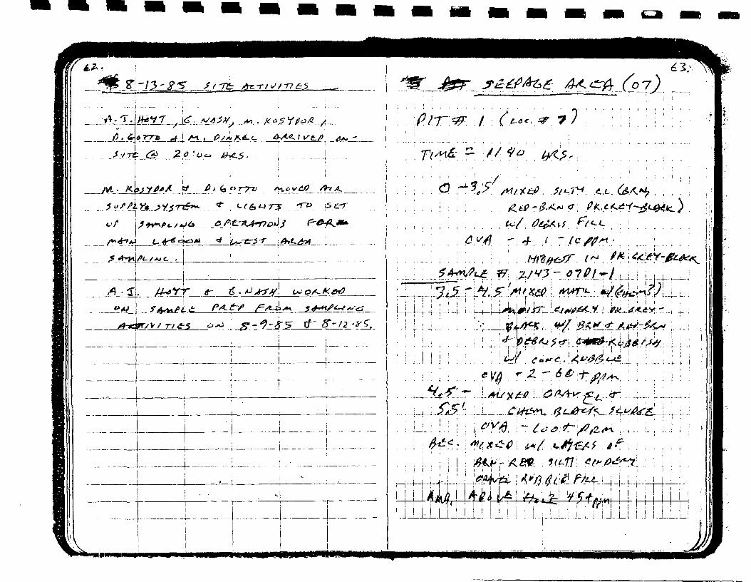
I
j^cr•>M
y-/2 -
. i
L'
i i i in
-.
1 : . : j . ; i ^ , ±.'to**
jijjji I I I I : i ' ' ' • • ' ' i ' I
_lJj_L... ! J...L[.l..lli..L_LLl.LJ.!J..L^

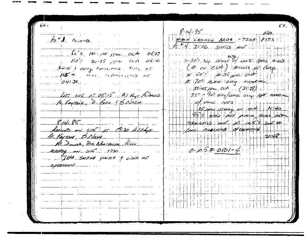
: ! : /! : , •'!_-!-.-!_; #|- /reT , f.y r:i i i i' ' : i ',

ear


^ LbLli ^
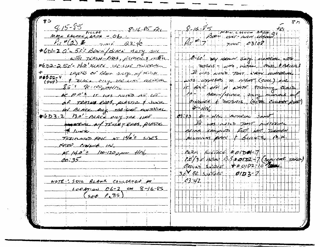


LL>r 6-?--
Sk*tc£~SL,L
9 X I O N B d d V

( fa-
j
0Z_-P.'_-2
02-01-1
A
A
4s)OZ-'Vl'JL
-"T"-^?—
OX-P2-V
^
f'-3LUO-
„ _
#**-
...0-.0&/&&
4* "3r-
-T£A$*
jff 3* &14**' r?jfc*1
jJn-_ j_f?r
K<rv*Vjy^*«i
_3^_-_
Ssf/Sjtf ^
</S>'j-
?&.?—
&/•<* <?
yfc.?_ £7&
•••••
^_ ._^/^^r'«£l /•/£%& \rCti-' ^<3y?<c."-*>_ - _A/&&
^^^r<f^^^f^&^. - i
r**/^_b .wA«*tH'- ^d^
'-
? 6s*-,--/><**
//^ n^— yfc^ /*y^*" -rus* .a»*^ — ~f^
jHufjgiZj/K'
/SUjti
&L.-A\@&Ctf2r /
r
//£>- /1 — /^ _!
—<$e*f-&+1&JT
*' CA!
t £/tner ,f'/o , £±+^ S~ r
l7~ &£t*
x4X£-
<w—£*iSS&tS-fjCJ~*r
Je^f*-
^3/C7l£-/*
/1>5 7" /4
(5'2D pal* Cxjft
^^m
. .. .
i
2"Z'aa
-:. ,if*7c3f//tc. i^f
AWTcZ
3$...f /t
S
•7Z> ^
*-fs3jt? -/ JA£
**&&-.- .
>-^ V/<ie- " 1kv7^"5 . .
i
fw>f\s
r)
fn^^i>
&6*fl'\
AT££t»-<^\C/ks^4'>~ -.-
»,***£*'<?*> )
-.
t
-•
]i
--i
—
-
--
•
*tf :-r-j^,-^-; • ; • • ; - • ^ • ; : ^ , , . . : , ; . .
; i • ' , j 1
| : TO • *£>/& ' i . i —- 1 t- i' . " ; ' i
i i ' ' i , , i ' !
: • ' . ' ' , ' ; ; i ! '' . • ; ' ! :
: . . : ; • ! • ! ' ' I : ' :
_^ ; . 1 L :— L -i L.L^-i-- '' 1 - i
' j i i i ' : ' i 1 1—1! • ; i : i i ! • : !
. _.. . . j . ! . . i . j . . ; 1 . r : : . . 1 . : . . . . . |-^ . L-i-._^-U_l
i ! 1
i : ! ^ 4 - 4 J _LLi • ' • • - , , ; j.. i1 ' : • •• ' ,r • ' ' ~ . ' ' \ '1 : . ' , . ; ; ; ii ' • ; • •• '• i ' ! - . i—• -•- • :- i .- - .- - p
; • ! i
\ : • • • ' ' ' • u i r^ l-i. . t ; i i
; ! ; ' : .' ' : .' ' ' i • i i ' i' : \ • i . .h i "^r IT
!

3 X IQN3ddV
XIQN3ddV

J XIdN]d.9 XIQN3ddV

3 XION3ddV
9 XIQN3JHV

g" ^ /*• g» 5 / /Tfc^ m Ai »s
tt-tTTt-r : • - ! - : - ' - } • - : - :

XI

t a 1~
-I
^^J VTOmiVN3d1


APPENDIX E:
Photo Log index Key
John Mathes & Associates, Inc.

PAXTON AVENUE LAGOONS
FIELD INVESTIGATION
PHOTO LOG INDEX KEY
PHOTO NUMBER PHOTO DESCRIPTION(ROLL-FRAME) SAMPLING LOCATION DISTANCE DIRECTION SHOT
III-l
III-2
III-3
III-4
III-5
III-6
III-7
III-8
III-9
111-10
III-ll
111-12
111-13
111-14
111-15
111-16
111-17
111-18
1 1 1-19
Note: 02-1-3,numbered
111-20
111-21
111-22
01-2
01-2
07-1
07-1
07-2
07-2
06-1
06-1
01-3
01-3
01-4
01-4
01-5
01-5
01-6
01-6
03-4
03-4
02-3
02-1-4, and 02-1-5 seenlocation most distant.
02-3
05-1
05-1 UV!|L»J,
Near
Far
Near
Far
Near
Far
Near
Far
Near
Far
Near
Far
Near
Far
Near
Far
Near
Far
Near
North
North-Northeast
North-Northeast
North-Northeast
Northeast
Northeast
East
East
North
Northwest
South
South-Southwest
North-Northwest
North-Northwest
South-Southeast
Southeast
East
East
West
in background, lowest
Far
Near
Far
West-Southwest
South-Southeast
Southeast
John Mathes & Associates, Inc.

rage
PHOTO NUMBER(ROLL-FRAME)
111-23
II1-24
IV-1
IV-2
IV-3
IV-4
IV-5
IV-6
IV-7
IV-8
IV-9
IV-10
IV-11
IV-12
IV-13
IV-14
IV-15
IV-16
IV-17
IV-18
IV-19
IV-20
IV-21
IV-22
IV-23
IV-24
PHOTO DESCRIPTIONSAMPLING LOCATION DISTANCE DIRECTION SHOT
01-1 Near
01-1 Far
06-2 Near
06-2 Far
01-7 Near
01-7 Far
Ol-L-6 (Oil) Near
Ol-L-6 (Oil) Far
Ol-L-5 (Oil) Near
Ol-L-5 (Oil) Far
Ol-BS-4 (Tube) Near
Ol-BS-4 (Tube) Far
Ol-BS-3 (Tube) Near
Ol-BS-3 (Tube) Far
Ol-BS-2 (Tube) Near
Ol-BS-2 (Tube) Far
01-BS-l (Tube) Near
01-BS-l (Tube) Far
01-1-1 (Tube) Near
01-1-1 (Tube) Far
05-SS (Soil Composite) Near
05-SS (Soil Composite) Far
04-10 Near
04-10 Far
04-9 Near
04-9 Far
Northeast
Northeast
East-Northeast
East-Northeast
West
North-Northwest
East-Southeast
East-Southeast
West
West-Southwest
North-Northeast
Northwest
East
Southeast
Southeast
Southeast
East-Northeast
Southeast
Northeast
Northeast
East
East-Southeast
West-Southwest
West-Southwest
West-Southwest
West-Southwest
John Mathes & Associates, Inc.

Page 3
PHOTO NUMBER(ROLL-FRAME)
PHOTO DESCRIPTIONSAMPLING LOCATION DISTANCE DIRECTION SHOT
V-l
V-2
V-3
V-4
V-5
V-14
V-15
V-17
VI-1
VI-2
VI-3
VI-4
VI-5
VI-6
VI-7
VI-8
VI-9
VI-10
VI-11
VI-12
VI-13
VI-14
VI-15
VI-16
VI-17
VI-18
VI-19
02-1
02-1
02-1
02-1
02-1
02-2
02-2
02-2
04-8
04-8
04-7 & 7A
04-7 & 7A
03-3
03-3
03-2
03-2
03-1
03-1
04-6
04-6
04-5
04-5
04-4
04-4
04-3
04-3
04-2 L'lViliTZ
Far
Far
Near
Near
Far
Near
Near
Near
Near
Far
Near
Far
Near
Far
Near
Far
Near
Far
Near
Far
Near
Far
Near
Far
Near
Far
* Near
Northwest
Northwest
Northwest
Southeast
Northwest
South
North
North
West-Southwest
Northwest
West-Southwest
Southwest
West-Southwest
Southwest
North
North-Northeast
Northeast
Northeast
East-Northeast
East-Northeast
Southeast
East-Southeast
Northeast
Northeast
North-Northeast
North-Northeast
Northwest
John Mathes & Associates, Inc.

pIIIIIIIIIIIIIIIII
PHOTO NUMBER(ROLL-FRAME)
VI-20
VI-21
VI-22
PHOTO DESCRIPTIONSAMPLING LOCATION DISTANCE DIRECTION SHOT
•fe
04-2
04-1
04-1
Far Northwest
Near East-Northeast
Far East
John Mathes & Associates, Inc.

IIIIIIIIIIIIIIIiI
APPENDIX F:
IEPA Background Analytical Data-Raised Area Soils Analysis
John Mathes & Associates, Inc.

r\
ENVIRODYNEENGINEERS
August 21, 19853015-01000
RECEIVED
Mr. Mark KroenigJohn Mathes & Assoc.210 West Sand Bank Rd.PO Box 330Columbia, IL 62236
Dear Mr. Kroenig:
Enclosed are the dioxin (TCDD) data requested by Ms. Mary Dinkel of theIllinois EPA for the Paxton lagoon soil/sludge samples. The packageincludes not only a tabulation of the pertinent information, but copiesof the chromatographs and mass spectra as well.
If you have any questions, please feel free to call.
Sincerely,
r\
John J/. Conig io'Project Manager
JJC/bsmEnclosure

TABLE B-1 - TCDD DATA REPORT FORM
Labi Envirodyne Engineers, Inc.
Case No.i 3015-01000
Batch/Shipment No.: Relative
Page 1 of 11
Report Datei 8/12/85
Column i SP-2330Ion
SampleNumber
Paxton UnkPaxton UnkMHASpike I
1985ED
5 8/75 8/78/78/7
EC
YYYY
wetWeight(grams)
1.05.010.010.0
GC/MS AnalysisTCDD ( ppb )Meas . D.L.
ND 1.10ND 0.6R
NO 0.0371 .08
Instr.l.D.
4444
1985Date
8/88/88/88/8
Time
1012111011581242
Abundance320/322
0.412.420.460.76
332/334
0.780.780.780.78
Surrogate
Meas
10.511.210.710.8
tng). * Accy
105112107108
Relative Ion Abundance320
116921108226
322
2B638237
10828
257 328a
85 109940 122330 28906
3166 21655
332
2166022465576341512
334
2763428937159953225
FRNNo.
T0493T0494T0495T0496
Notest RB • Reagent BlankFB • Field Blank
MB - Method BlankPRN • File Reference Number
D • Duplicate/Fortified Field BlankD.L. • Detection Limit
N • Native TCDD ,SplkeND - Not Detected
R - Rejected Data
"Corrected for contribution by native TCDDi 0.9* of m/z 322 subtracted.

r-^^:^^:^"r^in^5,'-r'^r:-':v ^^W:::"^^^ -"^ ILLINOIS ENVIRONMENTAL PROTECTION AGENCY MEMORANDUM
August 23, 1985
Gary King '"*:
Mary E. Dinkel
0316000067 - Cook CountyChicago/Paxton Ave. LagoonFOI Request for Paxton Ave. Lagoon
This is to inform you that Mr. James Ambroso, ComplianceManager for Land and Lakes Company, which is located di-rectly west of .the Paxton Avenue Lagoon site, is submit-ting a Freedom of Information request regarding the R Iactivities that have recently been completed this pastAugust 17, 1985.
Please be advised that Land and Lakes may be involved Inlitigation that is undertaken for this site once final.;property ownership is determined.
MED:bf/6
cc: HJivision FileMitch LevinJim JansseA
any
11- 532-0570

• • • • • M I I I I M I I I I S I B
Instr.I.D.
notNunber
Dat«(1985)
T0040TOOSOT0051T0052T0055T0056T0057T0058T0061T0062T0063T0066
Solution ID Codes t
4/24/24/24/24/24/24/24/24/24/24/24/3
SolutionTine I.D.
091311 1 J1158124315421610165010252033210321590002
PCCC1CC2CC3CC1CC2PCCC3CC1CC2CC3PC
320
170201335730385139649
16263175713687174939146902668817464616740
FORM B-2. INITIAL CALIBRATION SUMMARYCasei 9 pt. Calibration
Peak Area (or Height)322
21399169803858317841919694043017334
223712186893408622232521253
323
2955
2221
2802
328
1090695161575512859756
1977011713822219559
PC • Performance checfc solutionCC1 • Concentration calibration solution No. 1 •CC2 • Concentration calibration solution No. 2 •CC3 - Concentration calibration solution No. 3 •
0.2 ug/ml1.0 ug/ml5.0 ug/ml
332
4465707833151230033872132621326337032760002749336R683834
334
5743490822405603836311237421004138476669777535392474034930
Native RFMeasured Mean
0.940.960.930.900.97
0.940.960..970.94 0.95
Surrogate RF1
Measured Mean
.11
.06
.03
.06
.05
.05
.11
.05
.04 1.06
TCDOI seiner
Resolution
1.5%
0.5%
1.0%

Date : < ft
Time: it'- 00 A.M.
Photograph By:
Location : Q 3 / & O O Q O 6 * ' ?
_ Coo £ _ Co.
/ L-A Voor-l-S
Comments; Photograph taken
toward the tJogjU p e^sT "ffct
o~f
RECEIVED
JUN211985

ILLINOIS ENVIRONMENTAL PROTECTION AGENCY
DATE: April 18, 1985
TO: Division File
FROM: M. Levin, Maywood/FOS
SUBJECT: Paxton Avenue Lagoons Visit0 3 1 6 0 0 0 C 6 7 - Cook County - Chicago/Paxton
MEMORANDUM
RECEIVED
10
,EP/VDLPC
Chuck Gruntman and I visited the Paxton Avenue Lagoons onApril 18, 1985. We observed two large oily ponds with numerousdead birds floating on the surface. The purpose of this visitwas to familiarize myself with the site.
cc: Northern Region
IL 532-0570

V .
FORM D-3. OONTINlltMG CALIBRATION SUMMARY - 2, 3,7,8-TCDO
Instr.I .D.
FRNNumber
Date(1985) Time
SolutionI .D.
4444
T0491T0492T0502T0503
8/88/88/88/B
0825091516231710
CC1PCCC1PC
Peafc Area (or Height)320
234091 1641 .2401110576
322
30046151583098313780
323
.
2084
-• 1734
328
18409214091975818389
332
11 852840fi6912247837493
334
1514285206215803048313
Native2,3,7,8-RF Surrogate Rf
Measured
0.99
0.98
Mean
0.93
0.93
Measured
1 .121.151 .161 .06
Mean
1 .06
1 .061 .06
TCDDI some r
Resolution
Solution ID Codes:
PCCC1
Performance check solutionConcentration calibration solution No. 0.2 ucj/ml
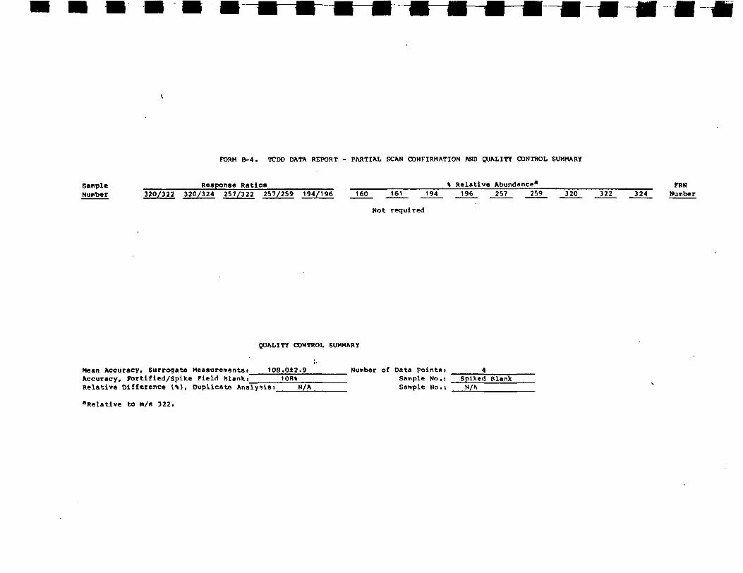
FORM B-4. TCDD DATA REPORT - PARTIAL SCAN CONFIRMATION AND QUALITY CONTROL SUMMARY
SampleNumber
Response Ratios % Relative Abundance8
320/322 320/324 257/322 257/259 194/196 160 161 194 196 257 259 320 322 324FRN
Number
Not required
QUALITY CONTROL SUMMARY
Mean Accuracy, Surrogate Measurements!Accuracy, Port!fled/Spike Field Blank:"Relative Difference (\), Duplicate Analysisi_
"Relative to i»/e 322.
108.0±2.9100%
N/A
Number of Data pointsiSample No.:Sample No.i
Spiked Blank

FORM B-5. GC OPERATING CONDITIONSConditions B
Column Coating
Film Thickness
Column Dimensions
Helium
Initial Temperature
Initial Time
Temperature Program
2,3,7,8-TCDD Retention Time
SP-2330
0.20 urn
60 m x 0.25 mm
26 psi
160 °C
3 minutes
25°/min to 240°C and hold
27.0 minutes

IIIIIIIII
APPENDIX G:
B Dioxin Analytical Data-Lagoons/South Pond Sludge/SedimentComposite Sample
I
I
I
I
I
I
I
IJohn Mathes & Associates, Inc.

aqualab inc.850 West Bartlett Rd.Bartlett IL 60103312-289-3100
Fi15 July 1985
Ms. Sue MurphyI EPADivision of Land Pollution2200 Churchill RoadSpringfield IL 62706
RECEIVED
JUL 17 1985
IEPA-DLPC
Dear Ms. Murphy:
I
I
I
I
I
I
Enclosed are the analytical results for the 2 soil samplesreceived by AQUALAB on 3 July 1985. These samples were from yourPaxton Ave. Lagoon project. These samples were analyzed foryour requested parameters. This work was performed under theContract Laboratory Program.
Analytical methods used by AQUALAB were USEPA approved methodsobtained from: "Test Methods for Evaluating Solid Waste,Physical/Chemical Methods," SW-846, Second Edition, July 1982.These methods were referenced in the Q.A. Project Plan.
Volatile organic analyses (VGA) were performed using EPAMethods 8240 and 5030. Aliquots of the samples are placed ina sparging device. Internal standards and deuterium labelledsurrogates are added to verify the analytical results andprovide qualitative and quantative references for everysample. The samples are then purged with helium and thevolatile organics are transferred to the gas stream. Theorganics are removed from the gas stream with a Tenax/SilicaGel trap. When purging is complete, the trap is rapidlyheated and the trapped organics transferred to the analyticalchromatographic column of a gas chromatograph/massspectrometer (GC/MS). As the individual components elute,complete mass spectra are collected and stored by a computersystem. The data are then processed by custom computerprograms and also evaluated manually to detect and quantifypriority pollutants. Identifications are verified bycomparison of the sample component mass spectrum andretention time of that standard component.
Base/Neutral and Acid (BN/A) compounds were analyzed usingEPA Methods 8250 and 3540. Aliquots of the samples areextracted with methylene chloride. The extracts areconcentrated and analyzed by GC/MS using the same approach asthe volatile organics.

aqualab inc.850 West Bartlett Rd. INI 17 1985Bartlett IL 60103312-289-3100 IEPA-DLPC
Ms. Sue Murphy15 July 1985Page Two
Pesticides and PCB's were analyzed using EPA Methods 8080 and3540. Aliquots of the samples are extracted with methylenechloride. The extracts are concentrated and cleaned up usingflorisil. The prepared extract is then analyzed by GC usingan electron capture detector.
Metals were analyzed by flame atomic absorption afterdigestion.
Results on these samples are in rag/Kg on a dry weight basis. Thedetection limits on the base neutral and acid compounds arehigher than normal due to the need for higher final volumes.This was because of the significant amount of extractablematerial. This material did not chromatograph very well and mayinclude organic acids. The extract was very dark in color.
The high organic background of these samples resulted in highdilutions. Because of these dilutions, extractable surrogatespike data could not be evaluated. In addition, the dilutionsrequired prior to metals analysis resulted in poor spike recoveryfor many metals.
If after reviewing these results or Q.C. Report #3 you have anyquestions, please feel free to call. AQUALAB has been pleased toprovide these analytical services for you.
Sincerely,
AQUALAB INC.
Robert N. BucaroDivision Manager
RNB/dabEncls.

aqualab inc.850 West Bartleit Rd.EJartlett IL 60103312-289-3100
ANALYTICAL REPORT
Ms. Sue MurphylEPA/Division of Land Pollution2200 Churchill Road _Springfield IL 62706
15 July 1985Sample No. 83958
SAMPLE RECEIVED: 07-03-85SAMPLE DESCRIPTION: Surface Composite G01
DATE TAKEN: 07-03-85
RECEIVED
JUL 1? 1985
JEPA-DLPCVOLATILE COMPOUNDS
mg/Kg Compound
<0.6 Benzene (4V)<0.6 Carbon Tetrachloride (6V)<0.6 Chlorobenzene (7V)<0.6 1,2-Dichloroethane (10V)<0.6 1,1,1-Trichloroethane (11V)<0.6 1.1-Dichloroethane (13V)<0.6 1,1,2-Trichloroethane (14V)<0.6 1,1,2,2-Tetrachloroethane (15V)<1.2 2-Chloroethylvinyl Ether (19V)<0.6 Chloroform (23V) .<0.6 1.1-Dichloroethylene (29V)<0.6 1.2-Cis Dichloroethylene<0.6 1,3 Dichlorobenzene<0.6 1.2-Trans-Dichloropropylene
mg/Kg Compound
<0.6 1,2-Trans-Dichloroethylene (30V<0.6 1.2-Dichloropropane (32V)<0.6 1,3-Cis-Dichloropropylene (33V<0.6 Ethylbenzene (38V)<0.6 Methylene Chloride (44V)<0.6 Bromoform (47V)<0.6 Dichlorobromomethane (48V)<0.6 Chlorodibromomethane (51V)1.4 Tetrachloroethylene (85V)<0.6 Toluene (86V)<0.6 Trichloroethylene (87V)<0.6 Xylenes, total<0.6 1,2 Dichlorobenzene<0.6 1,4 Dichlorobenzene
Results on a dry weight basis,
Robert N. Bucaro

inc.50 West Bartlett Rd.lartlett IL 60103, 12-289-3100
ANALYTIC AIL REPORT
4s. Sue MurphylEPA/Division of Land Pollution2200 Churchill RoadSpringfield IL 62706
15 July 1985Sample No. 83958
SAMPLE RECEIVED: 07-03-85SAN.PLE DESCRIPTION: Surface Composite G01
DATE TAKEN: 07-03-85
ing/Kg Compound
<19<Ui!<19
<97<97
(8B)
Acenaphthene (IB)Benzidine (5B)1,2,4-TrichlorobenzeneHexachlorobenzene (9B)Hexachloroethane (12B)Bis(2-chloroethyl)Ether (18B)2-Chloronaphthalene (20B)3,3'-Dichlorobenzidine (28B)2,4-Dinitrotoluene (35B)2,6-Dinitrotoluene (36B)Fluoranthene (39B)4-Chlorophenyl Phenyl Ether (40) <194-Bromophenyl Phenyl Ether (41B) <19Bis(2-Chloroisopropyl)Ether (42) <19Bis(2-Chloroethoxy)Methane (43B) <19Hexachlorobutadiene (52B) <19Hexachlorocyclopentadiene (53B) <19Isophorone (54B) <19Naphthalene (55B) <19
RECEIVEDBASE/NEUTRAL COMPOUNDS
JUL 17 1985mg/Kg Compound
IEPA-DLPCNitrobenzene (56B)N-Nitrosodimethylamine (61B)N-Nitrosodiphenylamine (62B)N-Nitrosodi-n-propylamine (63B)Bis(2-Ethylhexyl)Phthalate (66B)Butyl Benzyl Phthalate (67B)Di-N-Butyl Phthalate (68B)Di-N-Octyl Phthalate (69B)Diethyl Phthalate (70B)Dimethyl Phthalate (71B)Benzo(a)Anthracene (72B)Benzo(a)Pyrene (73B)Benzo(b)Fluoranthene (74B)Benzo(k)Fluoranthene (75B)Chrysene (76B)Acenaphthylene (77B)Anthracene (78B)Benzo(ghi)Perylene (79B)Fluorene (BOB)Phenanthrene (8IB)Dibenzo(a,h)Anthracene (82B)Ideno(l,2,3-cd)Pyrene (83B)Pyrene (84B)
ACID COMPOUNDS
2,4,6-Trichlorophenol (21A)4-Chloro-3-Methylphenol (22A)2-Chlorophenol (24A)2,4-Dichlorophenol (31A)2,4-Dimethylphenol (34A)2-Nitrophenol (57A)2.4,5-Trichlorophenol
Results on a dry weight basis.
<97 4-Nitrophenol (58A)<97 2,4-Dinitrophenol (59A)<97 2-Methyl-4,6-dinitrophenol (60A)<97 Pentachlorophenol (64A)<19 Phenol (65A)<19 2-Methylphenol<19 4-Methylphenol
fly

aqualab inc.850 We:5t Bartlett Rd.Baillett IL 60103312-289-3100
ANALYTIC AIL REPORT
Ms. Sue MurphylEPA/Division of Land Pollution2200 Churchill RoadSpringfield IL 62706
15 July 1985Sample No. 83958
SAMPLE RECEIVED: 07-03-85SAMPLE DESCRIPTION: Surface Composite G01
PESTICIDES
ing/Kg Compound
<0.0125<0.0249320.<0.0249<0.0249<0.0249<0.0125<0.0249X0.0249<0.0249K0.0249<0.0125<0.0125<0.125
Aldrin (89P)Dieldrin (90P)Chlordane (91P)4,4'-DDT (92P)4,4'-DDE (93P)4,4'-ODD (94P)alpha-Endosulfan (95P)beta-Endosulfan (96P)Endosulfan Sulfate (97P)Endrin (98P)Endrin Aldehyde (99P)Heptachlor (100P)Heptachlor Epoxide (101P)Methoxychlor
DATE TAKEN: 07-03-85
RECEIVED
JUL 17 1385
IEPA-DLPC
mg/Kg Compound
<0.0125<0.0125<0.0125<0.0125<0.125<0.249<0.125<0.125<0.12511.2<0.125<0.125<0.0249
Alpha-BHCbeta-BHCgamma-BHCdelta-BHCPCB-1242PCB-1254PCB-1221PCB-1232PCB-1248PCB-1260PCB-1016ToxapheneMirex
(102P)(103P)(104P)(105P)(106P)(107P)(108P)(109P)(HOP)(HIP)(112P)(113P)
Results on a dry weight basis.
Robert N. Bucaro
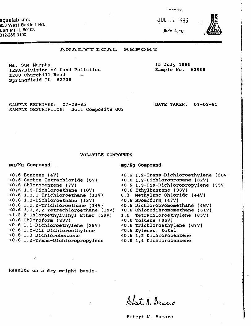
aqualab inc.350 West Bartlett Rd.Bartlett IL 60103312-289-3100
JUL .i !d85
ANALYTIC AIL REPORT
Ms. Sue MurphylEPA/Division of Land Pollution2200 Churchill Road _Springfield IL 62706
15 July 1985Sample No. 83959
SAMPLE RECEIVED: 07-03-85SAMPLE DESCRIPTION: Soil Composite G02
DATE TAKEN: 07-03-85
VOLATILE COMPOUNDS
ing/Kg Compound
•CO. 6 Benzene (4V)<0.6 Carbon Tetrachloride (6V)<0.6 Chlorobenzene (7V)<0.6 1,2-Dichloroethane (10V)<0.6 1,1,1-Trichloroethane (11V)•CO.6 1,1-Dichloroethane (13V)<0.6 1,1,2-Trichloroethane (14V)•CO. 6 1,1,2,2-Tetrachloroethane (15V)<1.2 2-Chloroethylvinyl Ether (19V)•CO. 6 Chloroform (23V)<0.6 1,1-Dichloroethylene (29V)<0.6 1,2-Cis Dichloroethylene<0.6 1,3 Dichlorobenzene<0.6 1,2-Trans-Dichloropropylene
mg/Kg Compound
<0.6 1,2-Trans-Dichloroethylene (30V<0.6 1,2-Dichloropropane (32V)<0.6 1,3-Cis-Dichloropropylene (33V<0.6 Ethylbenzene (38V)0.7 Methylene Chloride (44V)<0.6 Bromoform (47V)<0.6 Dichlorobromomethane (48V)<0.6 Chlorodibromomethane (51V)1.0 Tetrachloroethylene (85V)<0.6 Toluene (86V)<0.6 Trichloroethylene (87V)<0.6 Xylenes, total<0.6 1,2 Dichlorobenzene<0.6 1,4 Dichlorobenzene
Results on a dry weight basis,
Robert N. Eucaro

aqualab inc.850 West Bartlett Rd.Bartlett IL 60103312-289-3100
ANALYTICAL REPORT
M:;. Sue MurphyIlvPA/Division of Land Pollution2:'.00 Churchill RoadSpringfield IL 62706
15 July 1985Sample No. 83959
SAMPLE RECEIVED: 07-03-85SAMPLE DESCRIPTION: Soil Composite G02
BASE/NEUTRAL COMPOUNDS
DATE TAKEN: 07-03-85
RECEIVED
JUL 17 1i
ing/Kg Compound mg/Kg Compound JEPA-DLPC
<1(5 Acenaphthene (IB)<126 Benzidine C5B)<16 1,2.4-Trichlorobenzene (8B)
Hexachlorobenzene (9B)Hexachloroethane (12B)Bis(2-chloroethyl)Ether (18B)2-Chloronaphthalene (20B)3,3'-Dichlorobenzidine (28B)2,4-Dinitrotoluene (35B)2,6-Dinitrotoluene (36B)Fluoranthene (39B)4-Chlorophenyl Phenyl Ether (40)
<16<16<16<16<16<16<16<16<16<16<16<16
4-Bromophenyl Phenyl Ether (41B) <16Bis (2-Chloroisopropyl) Ether (42) <16Bis(2-Chloroethoxy)Methane (43B) <16Hexachlorobutadiene (52B) <16Hexachlorocyclopentadiene (53B) <16Isophorone (54B) <16Naphthalene (55B) <16
Nitrobenzene (56B)N-Nitrosodimethylaraine (61B)N-Nitrosodiphenylamine (62B)N-Nitrosodi-n-propylamine (63B)Bis(2-Ethylhexyl)Phthalate (66B)Butyl Benzyl Phthalate (67B)Di-N-Butyl Phthalate (68B)Di-N-Octyl Phthalate (69B)Diethyl Phthalate (70S)Dimethyl Phthalate (71B)Benzo(a)Anthracene (72B)Benzo(a)Pyrene (73B)Benzo(b)Fluoranthene (74B)Benzo(k)Fluoranthene (75B)Chrysene (76B)Acenaphthylene (77B)Anthracene (78B)Benzo(ghi)Perylene (79B)Fluorene (80B)Phenanthrene (8IB)Dibenzo{a,h)Anthracene (82B)Ideno(l,2,3-cd)Pyrene (83B)Pyrene (84B)
ACID COMPOUNDS
<H5
<7H
Results
2,4-2-2,2,2-2,
4.6-Trichlorophenol (21A) <78Chloro-3-Methylphenol (22A) <78Chlorophenol (24A) <784-Dichlorophenol (31A) <784-Dimethylphenol (34A) <16Nitrophenol (57A} <164,5-Trichlorophenol <16
on a dry weight basis.
4-Nitrophenol (58A)2,4-Dinitrophenol (59A)2-Methyl-4.6-dinitrophenol (60A)Pentachlorophenol (64A)Phenol (65A)2-Methylphenol4-Methylphenol

aqualab inc.850 West Bartlett Rd.Bailletl IL 60103312-289-3100
JUL i.7
IEPA-DLPC
ANALYTICAL REPORT
Ms;. Sue MurphyIlSPA/Division of Land Pollution2I200 Churchill RoadSpringfield IL 62706
15 July 1985Sample No. 83959
SAMPLE RECEIVED: 07-03-85SAMPLE DESCRIPTION: Soil Composite G02
DATE TAKEN: 07-03-85
PESTICIDES
mcr/Kg Compound
<0.0108 Aldrin (89P)<0.0215 Dieldrin (90P)170. Chlordane (91P)<0,,0215 4.4'-DDT (92P)<0.0215 4,4'-DD£ .(93P)<0,,0215 4, 4'-ODD (94P)<0,,0108 alpha-Endosulfan (95P)<C..0215 beta-Endosulfan (96P)<C.0215 Endosulfan Sulfate (97P)<C.0215 Endrin (98P)<0.0215 Endrin Aldehyde (99P)<G.0108 Heptachlor (100P)<0.0108 Heptachlor Epoxide (101P)<0.108 Methoxychlor
mg/Kg Compound
<0.0108<0.0108•C0.0108<0.0108<0.108<0.215<0.108<0.108<0.1089.47<0.108<0.108<0.0215
Alpha-BHCbeta-BHCgamma-BHCdelta-BHCPCB-1242PCB-1254PCB-1221PCB-1232PCB-1248PCB-126OPCB-1016ToxapheneMirex
(102P)(103P)(104P)(105P)(106P)(107P)(108P)(109P)(HOP)(HIP)(112P)(113P)
Results on a dry weight basis.
Robe'rt N. Bucaro

aqualap inc.8150 West Bartlett Rd.Barllett iL 60103312-289-3100 JUL 1? 1985
^ ^ ^ ^ ^ ^ ^ ^ ^ ^
RE1PORT
Ms. Sue MurnhyIEPA-DIVISION OF LAND POLLUTION2200 ChurchillSpringfield IL 62706
15 July 1985Sample No. 83958
.SAMPLE DESCRIPTION: Surface Composite G01
Date Taken: 07-03-85 1115 d Da,te Received: 07-03-85
Solids, tot. 66.58
Results on a dry weight basis:
CyanideAluminumAntimonyArsenicBariumBerylliumCadmiumChromiumCobaltCopperIron, totalLeadManganeseMercuryNickelSeleniumSilverThalliumZincTinVanadium
0.6714,000.
6.366.
6.8116.Not Determined559.24,800.840.1370.0.3577.
4.553.637.
45.
mg/Kgmg/Kgmg/Kgmg/Kgmg/Kgmg/Kgmg/Kgmg/Kg
mg/Kgmg/Kgmg/Kgmg/Kgmg/Kgmg/Kgmg/Kgmg/Kgmg/Kgmg/Kgmg/Kgmg/Kg
Robert N. Bucaro

I aqualab inc.1 8:>() West Bartlett Rd.
E.artlelt IL 601033 •» 2-289-3100
/ '•!
Ms. Sue MurphyIEPA-DIVISION OF LAND POLLUTION2200 ChurchillSpringfield IL 62706
REIPOFtT
15 July 1985Sample No. 83959
JUL 1? 1965
IEPA-DLPC
SAMPLE DESCRIPTION: Soil Composite G02
Date Taken: 07-03-85 1115 d Date Received: 07-03-85
Solids, tot. 89.15
Results on a dry weight basis:
CyanideAluminumAntimonyArsenicBariumBerylliumCadmiumChromiumCobaltCopperIron, totalLeadManganeseMercuryNickelSeleniumSilverThalliumZincTinVanadium
2.09050.<1.6.382.<1.7.4200.Not Determined808.32,800.2560.2600.<0.0184.<1.4.232.1160.26.64.
mg/Kgmg/Kgmg/Kgmg/Kgmg/Kgmg/Kgmg/Kgmg/Kg
mg/Kgmg/Kgmg/Kgmg/Kgmg/Kgmg/Kgmg/Kgmg/Kgmg/Kgmg/Kgmg/Kgmg/Kg
Robert N. Bucaro