george c. marshall space flight center, huntsville, alabama · pdf filedrilled and etched...
TRANSCRIPT

NASA TECHNICAL
MEMORANDUMN._.S& TM X-53453
August, 1966
i-
f
THE FABRICATION OF BERYLLIUM- VOLUME
METAL REMOVAL TECHNIQUES
By R. F. Williams and S. E. Ingels
Manufacturing Engineering Laboratory
III.
NASA
NL7L19657Z (ACCESmlON NUMBER)
_3
{f, IASA CR OR TMX OR AD N'_'_4BER)
(THRU}
/
( C 0 DTS ,'
(CATE _lrO RY)
George C. Marshall
Space Flight Center,
Huntsville, Alabama
https://ntrs.nasa.gov/search.jsp?R=19670010328 2018-05-23T21:29:05+00:00Z


v
TECHNICAL MEMORANDUM X-53453
THE FAB1RICATION OF BERYLLIUM - VOLUME III.
METAL REMOVAL TECHNIQUES
ABSTRACT
This report documents the metal removal techniques \
developed for the fabrication of beryllium aerospace vehicle \._tructure._. It is Volume III of a six volume set of technical
reports entitled "The Fabrication of Beryllium. " Proven produc-
tion techniques for the drilling, routing, and abrasive wheel cut-
ting of both sheet and plate gauges of material are presented.
Established techniques for the precision machining of hot-pressed
block and extruded rod are reviewed, Chemical milling solution
strengths and metal removal rates are investigated; and the
optimum Electrical Discharge Machining (I_DM) power and fre-
quency settings, and electrode materials, are correlated with the
resulting metal removal rates, surface finishes and elapsed machine
times. Metallographic and microphotographic techniques were
used for comparison and failure analyses.
NASA-GEORGE C. MARSHALL SPACE FLIGHT CENTER

_q

NASA-GEORGE C. MARSHALL SPACE FLIGHT CENTER
TECHNICAL MEMORANDUM X-53453
THE FABRICATION OF BERYLLIUM - VOLUME III.
METAL REMOVAL TECHNIQUES
By P. F. Williams and S. E. Ingels
The other Volumes of Technical Memorandum X-53453 are:
Vol. I .
Vol. I I.
Vol. IV.
Vol. V.
Vol. VI.
A Survey of Current Technology - _ .i. " "' ":_:'
Forming Techniques for Beryllium Alloys
Surface Treatments for Beryllium Alloys ","_',,
Thermal Treatments for Beryllium Alloys- \
Joining Techniques for Beryllium Alloys k .....
MANUFACTURING ENGINEERING LABORATORY
L/
/v

ACK NOWL EDGEMENT
The work accomplished to generate the information en-
closed in this report was performed under Contract NAS8-11798
by Large Space Vehicle Programs, Space Systems Division,
Lockheed Missiles and Space Company. The program encom-
passes the development and documentation of needed new manu-
facturing techniques and fabrication methods suitable for the appli-
cation of beryllium and beryllium alloys in space flight vehicle
structures.
Mr. R. F. Williams, NASA Advanced Manufacturing
Programs, was the Project Manager of this effort under the
management of Mr. A.J. Steele, Manager, NASA Engineering
Programs, Lockheed Missiles and Space Company. The work
was performed under the technical direction of Mr. S. E.
Ingels assisted by Mr. C. Fruth in preparation of the final
report.
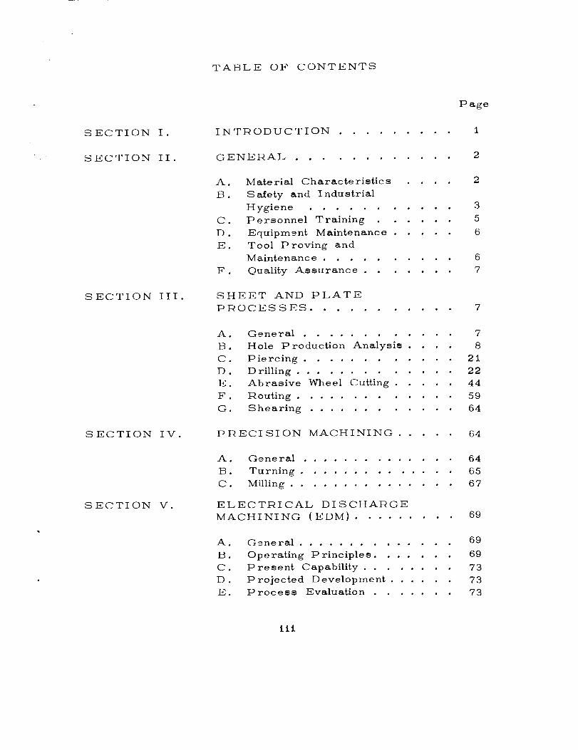
TABLE OF CONTENTS
SECTION I.
SECTION II.
SECTION III.
SECTION IV.
SECTION V.
INTRODUCTION .........
GENERAL ............
A. Material Characteristics ....
B. Safety and Industrial
Hygiene ...........
C. Personnel Training ......
D. Equipmgnt Maintenance .....
E. Tool Proving and
Maintenance ..........
F. Quality Assurance .......
SHEET AND PLATE
PROCESSES ......
Page
I
2
2
3
5
6
6
7
• • • , • 7
A. General ............ 7
B. Hole Production Analysis .... 8
C. Piercing ............ 21
D . Drilling ............. 22
E. Abrasive Wheel Cutting ..... 44
F. Routing ............. 59
O. Shearing ............ 64
PRECISION MACHINING ..... 64
A ,
B.
C.
General .............. 64
Turning .............. 65
MHling ............... 67
CTRICAL DISCHARGE
HINING (EDM) ......... 69
ELE
MAC
69General ..............
Operating Principles ....... 69
Present Capability ........ 73
Projected Development ...... 73
P rocess Evaluation ....... 73
A •
B.
C.
D.
E.
iii

TABLE OF CONTENTS (Cont.)
SECTION VI.
SECTION VII.
CHEMICAL MILLING .......
A. General ............
B . P resent Capability ........
C. Process Evaluation .......
D . lqe sults .............
CONCLUSIONS AND
RECOMMENDATIONS .......
Page
84
84
85
85
92
114
iv
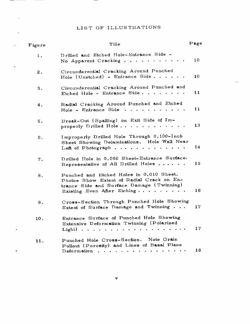
LIST OF ILLUSTRATIONS
F igu re
1.
,
•
B
•
•
•
,
10.
ll.
Title
Drilled and Etched Hole-Entrance Side -
No Apparent Cracking ..........
Circumferential Cracking Around Punched
Hole (Unetched) - Entrance Side ....
Circumferential Cracking Around Punched andEtched Hole - Entrance Side .......
Radial Cracking Around P.unched and Etched
Hole- Entrance Side ............
Break-Out (Spalling) on Exit Side of Im-
properly Drilled Hole ...........
Improperly Drilled Hole Through 0.100-Inch
Sheet Showing Delaminations. Hole Wall Near
Left of Photograph .............
Drilled Hole in 0.060 Sheet-Entrance Surface.
Representative of All Drilled Holes ......
Punched and Etched Holes in 0.010 Sheet.
Photos Show Extent of Radial Crack on En-
trance Side and Surface Damage (Twinning)
Existing Even After Etching ........
Cross-Section Through Punched Hole Showing
Extent of Surface Damage and Twinning . . .
Entrance Surface of Punched Hole Showing
Extensive Deformation Twinning (Polarized
Light) ....................
Punched Hole Cross-Section• Note Grain
Pullout (Porosity) and Lines of Basal Plane
D efo rmation ...............
Page
10
10
II
11
i3
14
i5
16
i7
i7
18
V
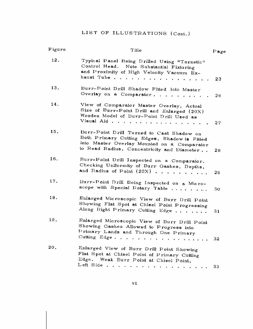
LIST OF ILLUSTRATIONS (Cont.)
Figure
12.
i3.
14.
i5.
16.
17.
i8.
19.
20.
Title
Typical Panel Being Drilled Using "Tornetic"
Control Head. Note Substantial Fixturing
and Proximity of High Velocity Vacuum Ex-
haust Tube .................
Burr-Point Drill Shadow Fitted into Master
Overlay on a Comparator ..........
View of Comparator Master Overlay, Actual
Size of Burr-Point Drill and Enlarged (20X)
Wooden Model of Burr-Point Drill Used as
Visual Aid ..................
Burr-Point Drill Turned to Cast Shadow on
Both Primary Cutting Edges, Shadow is Pitted
into Master Overlay Mounted on .a, Comparator
to Read Radius, Concentricity and Diameter..
Burr-Point Drill Inspected on a Comparator.
Checking Uniformity of Burr Gashes, Depths,
and t2adius of Point (20X) ..........
Burr-Point Drill Being Inspected on a Micro-
scope with Special IRotary Table .........
Enlarged Microscopic View of Burr Drill Point
Showing Flat Spot at Chisel Point Progressing
Along Right Primary Cutting Edge .......
Enlarged Microscopic View of Burr Drill Point
Showing Gashes Allowed to Progress into
Primary Lands and Through One Primary
Cutting Edge ..................
Enlarged View of Burr Drill Point Showing
Flat Spot at Chisel Point of Primary Cutting
Edge. Weak Burr Point at Chisel Point,
Left Side ..................
P age
23
26
27
28
29
3O
31
32
33
v£

LIST OF ILLUSTRATIONS (Cont.}
Figure
21.
22.
23.
24.
25.
26.
27.
28.
29.
30.
Title
Enlarged Microscopic View of Burr Drill
Point Showing Gashes Allowed to Progress
into Both Primary Lands ..........
Enlarged Microscopic View of Burr Drill
Point Showing Gash Progressed Into Primary
Land Near Chisel Point and in Such a
Manner as to Weaken Trailing Burr to Cause
Fracture .................
Enlarged Microscopic View of Burr Drill
Point Showing Gash was Allowed to Progress
into Primary Land at Chisel Point ......
Enlarged View of Burr Points and Relief
Angles ...................
Enlarged View of Primary Cutting Edge and
Length and Depth of Gash for Cross-Overof Point ...................
Enlarged View of Angles of Burr-Drill Points,
Primary Cutting Edge and Angle of l_elief of
Primary Land ................
Correctly Drilled Hole Using Recommended
Procedures. Exit Side (Unetched) ......
Cross-Section Through Good Hole Using
Recommended Procedures (Unetched} . . .
Cross-Section Through Good Hole - Minor
Twinning Evident (Unetched} .........
Hole Drilled with Dull Drill Showing Radial
Cracking { Unetched) .............
P age
34
35
36
37
38
39
42
42
43
45
vii

LIST OF ILLUSTRATIONS (Cont.)
Figure
31.
32.
33.
34.
35.
36.
37.
38.
39.
40.
41.
Title Page
Hole Drilled with Dull Drill Showing Radial
Cracking and Bridging from Hole to Hole . . . 45
Hole Drilled with Dull Drill. Surface of
Sheet Showing Radial Crack Emanating
from l_ough Surface of Hole (Unetched) .... 46
High Magnification of Radial Crack Caused
by Drilling Hole with Dull Drill ......... 46
Cross-Section of Hole Drilled with Dull
Drill (Unetched) ............... 47
Cross-Section of Hole Drilled with Dull
Drill Showing Spalied Edge (Unetchekl} ..... 47
Cross-Section of Hole Drilled with Dull
Drill at High Magnification (Unetched) ..... 48
Hole Drilled with Improperly Sharpened
Drill. Note Heavy Burr on Exit Side
(Unetched) ................. 49
Cross-Section Through Hole Drilled
with Improperly Sharpened Drill
(Unetched) .................. 49
Holes Drilled Using Excessive Feed Rates.
Note Spalling on Exit Side (Unetched) .... 50
Cross-Section of Hole Drilled Using
Excessive Feed !_ate. Note SpalIed Region(Unetched) ................. 50
Cross-Section of Hole Drilled at Excessive
Feed Pate. Note Chipping on Flat Portion
of Hole Surface (Unetched) . ......... 51
viii

LIST OF ILLUSTI_ATIONS (Cont.)
43.
44
45
46.
47
48
49
50.
51.
Title
Large Capacity Precision Abrasive Cut-Off S aw ..................
Cross-Section of Surface Cut Dry on
Abraslve Wheel. Feed Rate 4.0 IPM
at 8 240 S FM ................
Cross-Section of Surface Cut Dry on
Abraslve Wheel. Feed Rate 4.0 IPM
at 8 240 AFM. Note Large Inclusion .....
Cross-Section of Surface Cut Dry on
Abraslve Wheel. Feed Rate 6.0 IPM
at 8,9.40 SFM ..............
Cross-Section of Surface Cut Dry on
Abraslve Wheel. Feed Rate 6.0 IPM
at 8 240 S FM ...............
Cross-Section of Surface Cut Dry on
Abrasive Wheel. Feed lqate 7.5 IPM
at 8 240 SFM ...............
Cross-Section of Surface Cut Dry on
Abras,ve Wheel. Feed Rate 7.5 IPM
at 8 240 SFM ...............
Cross-Section of Surface Cut on Abrasive
Wheel Using Coolang. Feed Rate 4.0 at
8,240 SFM .................
Cross-Section of Surface Cut on Abrasive
Wheel Using Coolant. Feed lqate 4.0 IPM
at 8,240 SFM ................
Abrasive Wheel Cut Surface - Lightly
Polished .................
Page
53
54
54
55
55
56
56
57
57
58
ix

LIST OF ILLUSTRATIONS (Cont.)
Figure
52.
53,
54.
55.
56.
57.
58.
59.
60.
61.
62.
63.
Title P age
lqouter Cut Surface - Lightly Polished .... 58
A Typical Panel in Router Fixture.
Note Substantial Support Structure and
Proximity of High Velocity Vacuum
I_xhaust Tube! ............ 61
Types of Cutters Used in Routing
Beryllium Sheet .............. 62
Cross-Section of Router Cut Surface 63
Cross-Section of Router Cut Surface 63
Cincinnati Model 24A31 i_lectrical Dis-
charge Machine with I_lox NPS D-60
Power Supply ............... 71
lqelationship Between Surface Finish and
Discharge Frequency ............ 72
Test Coupons and I_DM l_lectrodes.
tqoughing l_lectrode on Right and FinishElectrode on Left ............. 74
Cross-Section of EDM Roughing Cut . 76
Cross-Section of EDM Roughing Cut . . 76
Cross-Section of EDM Finish Cut at
2,000 CPS, Metal l_emoval lqate 1.140
Cu. In,/Hr .............. 79
Cross-Section of I_DM Finish Cut at
2,000 CPS. Metal Removal !_ate 1. 140
Cu. In./Hr ................ 79
x

LIST OF ILLUSTRATIONS {Cont.}
Figure
64
65
66.
67
68
69
7O
71
72
73.
Title P age
Cross-Section of IEDM Finish Cut at
8,000 CPS. Metal lqemoval IRate
0.38 Cu. In./Hr .............. 80
Cross-Section of EDM Finish Cut at
8,000 CPS. Metal Removal IRate
0.38 Cu. In./Hr .............. 80
Cross-Section of I_DM Finish Cut at
130,000 CPS. Metal Removal IRate
0.285 Cu. In./Hr .............. 81
Cross-Section of EDM Finish Cut at
130,000 CDS. Metal Removal Rate
0.285 Cu. In./Hr .............. 81
Cross-Section of EDM Finish Cut at
130,000 CDS. Metal Removal Rate
0. 125 Cu. In/Hr .............. 82
Cross-Section of EDM Finish Cut at
130,000 CPS. Metal Removal Rate
0.125 Cu. In./Hr .............. 82
Cross-Section of EDM Finish Cut at
32,000 CP S . Metal IRemoval Rate
0.045 Cu. In./Hr ............ 83
Cross-Section of IEDM Finish Cut at 32,000
CPS. Metal l_emoval IRate 0.045 Cu.
In./Hr ................... 83
Chemical Milling and Etching Facility ..... 86
Macrophotograph of "As IReceived" Beryl-
lium .................... 93
xj

LIST OF ILLUSTRATIONS (Cont.)
Figure
74.
77.
78.
79.
80.
81.
82.
83.
84.
Title Page
Macrophotograph of Area ChemicallyMilled with a 10% Solution of Sulfuric
Acid ( Specimen No. 121 .......... 93
Profile of "As l_eceived" Beryllium ..... 94
Profile of Area Chemically Milled with
a 10% Solution of Sulfuric Acid ....... 95
Macrophotograph of Area ChemicallyMilled with a 10% Solution of Sulfuric
Acid (Specimen No. 21) .......... 96
Macrophotograph of Area ChemicallyMilled with a 7.5% Solution of Sulfuric
Acid (Specimen No. 16) .......... 96
Profile of Area Chemically Milled with
a 10% Solution of Sulfuric Acid ....... 97
Profile of Area Chemically Milled with
a 7.5% Solution of Sulfuric Acid ....... 98
Macrophotograph of Area ChemicallyMilled with a 12.5% Solution of Sulfuric
Acid (Specimen No. i8) ......... 99
Macrophotograph of Area Chemically
Milled with a 7.5% Solution of Ammonium
Blfluoride (Specimen No. 15) ........ 99
Profile of Area Chemically Milled witha 12.5% Solution of Sulfuric Acid ..... 100
Profile of Area Chemically Milled with
a 7.5% Solution of Ammonium Biflouride . . . 101
xii

LIST OF ILLUSTRATIONS (Cont.}
Figure
85.
86.
87.
88.
89.
90.
91.
92.
93.
94.
Title P age
Macrophotograph of Area ChemicallyMilled with a 10% Solution of Ammonium
Bifluoride (Specimen No. 6) ......... 102
Macrophotograph of Area ChemicallyMilled with a 15% Solution of Ammonium
Biiluoride (Specimen No. 10) ......... 102
Profile of Area Chemically Milled with
a 10% Solution of Ammonium Bifluoride ..... 103
Profile of Area Chemically Milled with
a 15% Solution of Ammonium Bifluoride ..... 104
Macrophotograph of Area ChemicallyMilled with a 20% Solution of Ammonium
E_ifluoride (Specimen No. 13) ......... 105
Macrophotograph of Area Chemically Milledwith a 30% Solution of Ammonium
Bifluoride (Specimen No. 23) ......... 105
Profile of Area Chemically Milled with
a 20% Solution of Ammonium Bkf}uoride ..... 106
Profile of Area Chemically Milled with
a 30% Solution of Ammonium Bifluoride ..... 107
Macrophotograph of Area ChemicallyMilled with a 45% Nitric Acid - 3%
Hydrofluoric Acid Solution (Specimen
No. 7) .................. • 108
Macrophotograph of Area ChemicallyMilled with a 50% Nitric Acid - 25%
Hydrofluoric Acid Solution (Specimen
No. 9) .................. • I08
xlil

LIST OF ILLUSTI_ATIONS (Cont.}
Figure
95.
96.
97.
98.
99.
i00.
Title
Profile of Area Chemically Milled with
a 45% Nitric Acid - 3% Hydrofluoric
Acid Solution ...............
Profile of Area Chemically Milled with
a 50% Nitric Acid - 25% Hydrofluoric
Acid Solution ...............
Macrophotograph of Area Chemically
Milled with a 50% Phosphoric Acid -
20% Sulfuric Acid Solution (Specimen
No. 4) ..................
Macrophotograph of Area Chemically
Milled with a 5 Parts (Vol.) Phosphoric
Acid - 2 Parts (Vol.) Sulfuric Acid -
5 Parts ( Vol, ) Water Solution ( Specimen
No. 8) ..................
Profile of Area Chemically Milled with a
50% Phosphoric Acid - 20% Sulfuric Acid
Solution ................
Profile of Area Chemically Milled with a
5 Parts (Vol.) Phosphoric Acid - 2
Parts (Vol.) Sulfuric Acid - 5 Parts
(Vol.) Water Solution .........
Page
109
110
111
111
i12
113
xiv
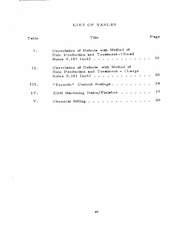
LIST OF TABLES
Table Title Page
I •
II.
IlI .
IV.
V.
Correlation of Defects with Method of
Hole P roduction and Treatment -( Small
Holes 0.167 Inch) .............
Correlation of Defects with Method of
Hole Production and Treatment - (Large
Holes 0.191 Inch) .............
" Tornetic" Control Settings .........
EDM Machining lqates/Finishes .......
Chemical Milling ...............
19
20
24
77
90
xv


THE FABRICATION OF BERYLLIUM - VOLUME III.
METAL REMOVAL TECHNIQUES
SECTION I. INTRODUCTION
The objectives of this task are the definition, development
and documentation of the beryllium fabrication operations classified
as "Metal l_emoval" in the Beryllium Fabrication Methods Develop-
ment Program Plan.
Maximum use was made of the established methods and
procedures currently being utilized in production operations. In
all cases, the verification and recording of pertinent data were
necessary; in many cases, e.g., Electrical Discharge Machining
(]?,]-)M) , additional development work also was required,
The procedure used in compiling this report was asfollows :
i. Conduct a detailed analysis of the metal removal
practices being used within industry.
2. Investigate_ evaluate and report upon the techniques
currently utilized with certain B_ryllium Shops.
3. Fabricate representative parts in accordance with
the requirements of approved production procedures.
4. Vary the production techniques sufficiently to incurintentional failure, and thus circumscribe limits.
5. Utilize metallographic and microphotographic methods
to evaluate both the satisfactory and the unsatisfactory results.

SECTION II. GENERAL
Due to the basic similarity of many facets of the various
beryllium metal removal methods, they are discussed separately
in this section to avoid repetition.
A. MATF_IAL CI-IAPACT_I_I S TI CS
The effect of the physical properties of beryllium
must be considered in almost all metal removal operations. When
subjected to chip-producing processes, it machines relatively easily
(somewhat similar to cast iron). However, due to the abrasive
nature of beryllium, carbide cutting tools must be used if adequate
tool life is to be attained. Sharp edges and reasonable chip-loads
nnu_t be maintained on the cutting tools to prevent the buildup of
c,:tting pressures. Pelatively low cutting speeds for carbide
tools, ranging from 75 to 300 surface feet per minute, are used.
F)ue to the low ductility of beryllium at room tempera-
ture, the pressures applied to the workpiece during machining
operations must be kept at a minimum level. During the entrance
to, or the exit from a cut, the speeds, feeds, and pressures must
be very low to avoid the fracturing or spalling of the workpiece.
The introduction of internal stresses into the work-
piece due to clamping action must be avoided. During the subse-
quent machining operations any additional forces due to improper
clamping can result in a cumulative stress level in excess of the
elastic limit of the material.
A similar failure may occur because of the deflection
of the workpiece due to excessive cutting force_ or the lack of
workpiece rigidity and/or fixture support. A common cause of
excessive cutting force is the resistance generated by a dull or
improperly ground cutter. Just as the cutting action nears corn-
pletion_ the c,:tting pressure is relieved sufficiently to permit the
sprln_back of the deflected ,¢vorkpiece to its unrestrained position.
As this occurs, the chip-load of the cutter is increased greatly,
a high radial force is generated, and failure of the workpiece
may result.

The high-heat capacity of beryllium, i.e., its ability
to absorb heat in a localized area, also must be given careful
consideration. For example, the localized heat produced along
one edge of the material by an abrasive saw used with insufficient
coolant will cause considerable expansion of the edge grains. This
heat tends to remain along the edge while the material a short
distance into the workpiece remains cool and unexpanded. These
differentials in ten0perature and expansion, if sufficiently large,
can cause corresponding degrees of small edge fractures.
Beryllium is highly notch sensitive. It is mandatory,
therefore, that the surfaces be protected from possible nicks and
scratches during handling, processing and transportation. Storage
shelves and transportation and handling devices should be free of
protruding nails, chips, etc., and should be lined with felt or a
similar protective material. D_3ring the processing phase, the
parts should be stored temporarily in individual containers or
nested with interleaves of protective paper. Operators must
practice caution at all times; must avoid setting the workpieces on
hard surfaces, dropping tools on, or striking the beryllium with
other hard or sharp objects which could cause the fracture ofthe material.
Beryllium forms a surface film of beryllium oxide
during its exposure to the high temperatures required for normal
processing. This film must be removed by wet sanding or light
grinding prior to mechanical or chemical cutting if reasonable toollife or consistent results are to be realized.
19. SAFETY AND INDUSTRIAL HYGIENE
The inhalation of high concentrations of beryllium dust
can cause serious illness; however, with the establishment and
maintenance of proper environmental controls, the material can
be handled safely during all roaching operations. Since the toxicity
of beryllium was realized in the late 1940¢s and effective dust con-
trol methods were instituted, no chronic beryllium disease trace-
able to this cause has been reported.

The basic hazards ericountered in working with
]_eryllium are:
i. The inhalation of high concentrations of beryllium
dust or fumes can have a deleterious effect on the respiratory
syster_ .
2. The presence of beryllium or its compounds in
any cut or wound tends to inhibit healing until the foreign rpaterial
is removed.
3. Contact with some of the compounds of beryl-
lium can cause a temporary dermatitis condition.
Safe working conditions can be established by per-
romping all beryllium metal rerr, oval operations in a separate
"]_eryllium Poom." Fach room is equipped with its own exhaust
ventilation and chip collection systems, and is maintained at a slight
negative pressure relative to the rest of the building to prevent
the possible contamination of adiaLcent areas. All chip-producing
rpachine tools must be equipped with close-capture high-velocity
exhaust I hoses which are maintained within one hose diameter
(approximately 3 inches) of the working face of the cutting tool.
A total enclosure must be used to control the fine dust or mist
created during such operations as wet or dry sanding and abrasive
wheel cutting. Acld-etching, chernical milling, and electrical dis-
charge rr_achining facilities are equipped with specialized exhaust
systerY_s. All dust-collecting surfaces, including machine tools,
should be "wet-wiped" once each clay, and the floor should be
cleaned and mopped once each shift.
F,mployees a_signed to the beryllium rooms receive
n_edlc-al exan_inations, including lung X-rays, prior to the initial
assignment and at six-n_onth intervals thereafter. Smoking is
restricted in the beryllium rooms, and all normal safety practices
such as the wearing of safety glasses, the reporting of all injuries,
however slight, to the medical unit, etc., are rigidly enforced.
Cotton shop coats are furnished, and the coats, towels, and
cloths are la,_ndered in special approved on-site facilities provided!
for this purpose. Only materials and equiprr_ent "which are free
from loose particles of beryllium are permitted to leave the beryl-
lium rooms. All the beryllium exhaust, ventilation and air-cleaning
oquipn_ent, as well as the industrial hygiene procedures, are
4

monitored constantly by an independent Safety and Industrial
Hygiene Organization.
C. P EI_ S ONNEL TI_AINING
Employees working in the beryllium rooms must be
fully informed of the correct methods, processes and handling
procedures for fabricating beryllium hardware. The personnel
also must be made aware of the basic hazards, and be thoroughly
indoctrinated in safety and industrial hygiene practices. Each
employee, therefore, is required to successfully complete a com-
pany-sponsored indoctrination and training course prior to his
assignment in a beryllium room• The subjects covered in this
course are outlined as follows:
•
•
a. Course Purpose
b. Advantages of Beryllium
c. Typical uses of Beryllium
d. Production of Beryllium - Block and Sheet
Fabrication Techniques for Beryllium Sheet
a. Forming
b. D rilling
c. Joining Parts
d. Cutting and Trimming
Handling Techniques for Beryllium Sheet
a. Specific Handling Requirements
b. Oeneral Handling Techniques
1. I ntroductlon

• Safety Techniques for Beryllium - All forms
a. Basic Hazards
b. I-Iazard Control Me_hods
D. EQUIPMENT MAINTENANCE
The primary responsibility for ensuring that the
equipment is functioning properly falls upon the machine operator.
Any malfunctions are reported to the supervisor.
The possibility of production delays resulting from
machine malfunction or breakdown is greatly lessened, and
r_achine accuracy is significantly preserved by the application of
a program of preventative maintenance. The following inspections
and maintenance services are provided by a plant engineering
organization at the following scheduled intervals:
1. Visual inspection of hydraulic fluid levels in
glass reservoirs - service as required - daily.
weekly.
q uarte fly.
.
•
Check spindle, slide and ways - lubricate -
Inspect electrical and mechanical operation -
°
semi- annually.
Drain, clean and refill hydraulic system -
E. TOOL PROVING AND MAINTENANCE
Due to the abrasive characteristics of beryllium,
the use of standard procedures for the initial proving and routine
maintenance of tooling is mandatory. It is recommended that the
fabrication of the first production pieces on a new tool be witnessed
by the tool designer. Thus, any necessary repairs or modifications
can be accomplished expeditiously, and the existence of any slight
dimensional deviations, well within the allowable tolerances, can
be noted and recorded. Peri'_dic inspections at regular intervals,
6

based on past experience and wear records, should be made by
tool inspection personnel. Any dimensional deviations should be
recorded and any necessary repairs be made. lQigid conformance
with such procedures will preclude most, if not all, rejections
due to tooling error.
F. 0UALI TY AS SUI_ANCE
All beryllium hardware is inspected for quality
assurance. In-process inspection is performed at appropriate
stages of the fabrication process as well as 100 percent inspection
at! the completion of the part, sub-assembly, or assembly. Due
to the very lir_ited number of qualified repair procedures, per-
fection in workmanship is literally required.
Conventional measuring and checking equipment is
used during the inspection operations. Visual examination for
the existence of cracks, delamination, spalling, etc., normally is
performed after chemical etching. This process tends to enlarge
any such defects and make them readily detectable without mag-
nification. This process is preferred over the more common
"Zyglo" inspection method which may not reveal extremely small
or tight cracks or fractures.
SECTION III. SHEET AND PLATE PNOCESSES
A. GENERAL
Cross-rolled beryllium sheet produced from vacuum
hot-pressed and sintered block is available commercially in standard
thicknesses ranging from 0.020 to 0.250 inch, and in sizes up to
36 by 96 inches. Larger sizes are available on special order.
Plate stock is available in thicknesses ranging from 0.250 to
1 inch. The standard thickness tolerance is approximately +_
I0 percent of the nominal gauge. The variation from true flatness
may be 2 to 3 percent as determined by measuring the point of
_reatest deviation from an applied straight edge, and expressing
this r_easurerr_ent as a percentage of the distance between the
contact points. Improper stress relieving operations also may
result in "waviness" or deviations from the drsired contour.
It is important, therefore, that the holding devices be designed
7
to accommodate such variations to avoid introducing high stresses
into the workpiece during the subsequent locating, supporting and/
or clamping operations.
Typical items fabricated from sheet and plate stock
include exterior skin panels, doors, frames, rings, and assorted
brackets. Most conventional sheet metal configurations can befabricated within normal tolerances.
B. HOLE PPODUCTION ANALYSIS
Evaluation of the comparative merits of the most
common methods for producing holes in sheet material has been
made, verified, augmented, and reported in this report.
During the initial study, a series of holes, 0.167
and 0. 191 inch in diameter, were punched and drilled in two
thicknesses of material, 0.060 and 0.100-inch, and the resulting
hole edges were metallurgically examined. In addition, the merits
of reaming and etching also were investigated. The results of
this investigation indicated that drilling followed by etching pro-
duced the highest quality holes. Reaming had a deleterious effect,
and piercing was somewhat detrimental to the integrity of the beryl-
lium surrounding the holes.
The extent and depth of microcracks and delamination,
and the presence of twins and porosities on both the hole and
edge surfaces were items of prime interest during the initial study.
The various holes evaluated during this study are listed as follows:
1. Four holes pierced in 0.060 and 0.100-inchsheet.
2. Four holes pierced and reamed in 0.060 and0. 100-inch sheet.
3. Four holes drilled in 0.060 and 0.100-inch
sheet.
4. Four holes pierced and etched in 0.060 inchand 0.100-inch sheet.

5. Four holes pierced, reamed, and etched in
0.060 and 0.100-inch sheet
6. Four holes drilled and etched in 0.060 and
0. 100-inch sheet.
i. Analysis Procedure. All holes were photo-
_raphed individually, from both sides of the sheet, at a ma_nifiba-
tion of ten diameters.
One specimen hole, representing each parameter,
was mounted so that the plane of polish was the surface through
which the punch or drill entered, i.e., the "top" surface. The
other specimen, also representing each parakneter, was cut
across the hole, mounted, and polished to present a cross-sec-
tional view of the hole.
All specimens were ground with silicon carbide
papers, up through 600 grit, and then were etched to remove
any surface delar_ination that had been produced by {he grinding
operation. The samples then were prepared for photographing
by conventional abrasive polishing methods.
A metallograph was used to examine the speci-
mens at low magnification. Both bright field and polarized light
illumination were used.
2. !_esults. Pertinent aspects of the macroscopic
and microscopic conditions of the holes are illustrated in Figure.s
I through Ii. The illustrated defective conditions are discussed
as follows :
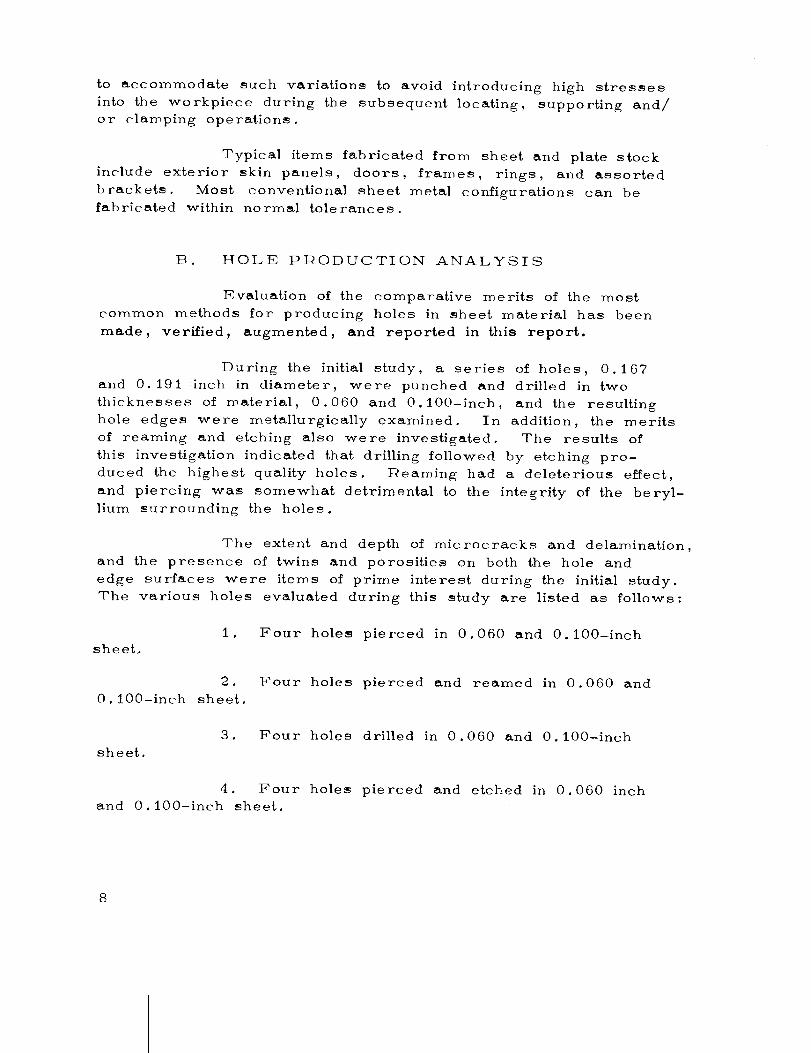
1. .A satisfactorily drilled hole is apparent
(Figure 1). T4owever, basal plan'e delamination may occur as
shown in Figure 6, and revealed by etching if improper drilling
procedures are used.
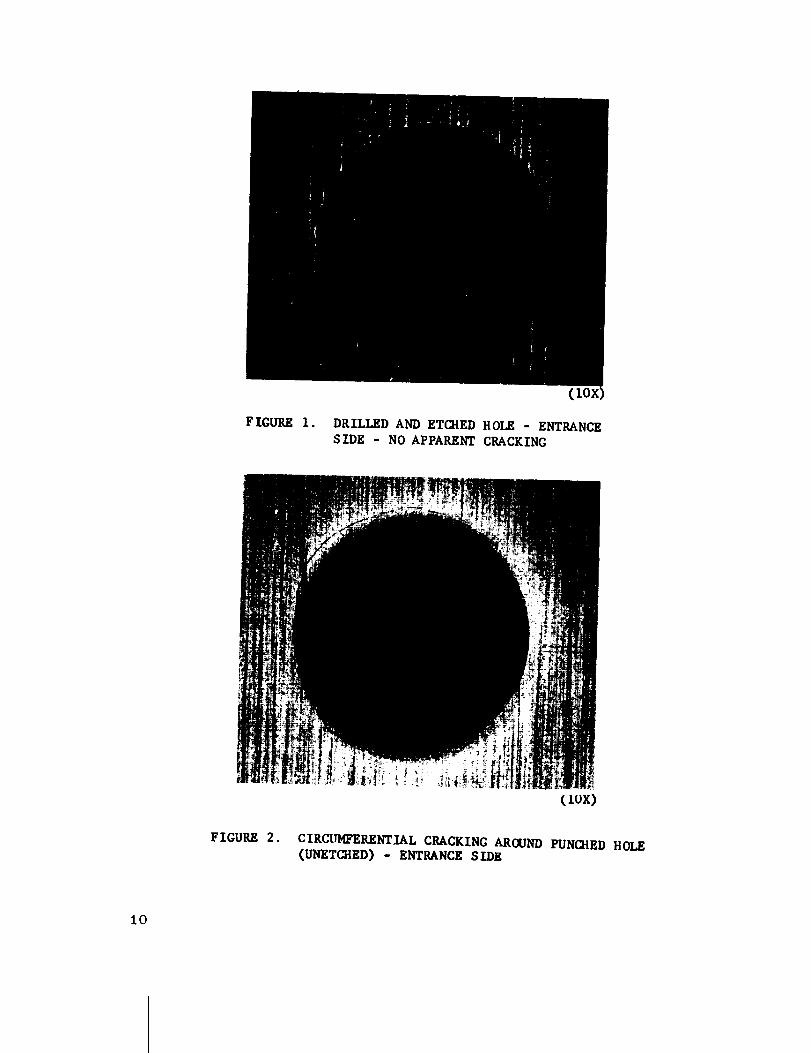
2. Circumferential cracks are visible on the
entrance surface of the punched hole (Figures 2, and 3). It
may be noted that the defect is much more visible after etching.
F ICUP,E 1.
(
DRILLED AND ETCIIED HOLE - ENTRANCE
S IDE - NO APPARENT CRACKING
FIGURE 2.
(1ox)
CIRCUMFERENTIAL CRACKING AROUND PUNCHED HOLE(UNETCHED) - ENTRANCE SIDE
10

FIGURE 3.
(fox)
CIRCUMFERENTIAL CRACKING AROUND PUNCHED AND ETCHED HOLE-
ENTRANCE SIDE
FIGURE 4.
(lox)
RADIAL CRACKING AROUND PUNCHED AND ETO_ED HOLE-
ENTRANCE SIDE
11

3. Radial cracks are visible on the entrance
surface of the punched hole (Figures 4 and 8). This type of
fracture, although easily seen without the utilization of visual aids,
is accentuated by etching. The extent of intra-grain damage, or
twinning, is clearly evident in Figure 8.
4. Break-out or spalling is clearly visible on the
exit surface of a drilled hole (Figure 5). This defect is typical
of the results obtained from operating a drill press in the con-
ventional manner with a normal two fluted drill of standard ge-
ometry.
5. Severe delaminations along basal planes are
shown here (Figure 6). This defect results from improper
drilling procedure.
6. The absence of surface damage around a
drilled hole is very evident (Figure 7).
7. A radial crack and severe deformation
(twinning) on the entrance side of a punched and etched hole are
shown here (Figure 8) .
8. Severe delamination is visible in this cross-
section of a punched hole (Figure 9). It may be noted that the
twinning increases progressively with hole depth.
9. Extensive surface daroage and twinning on
the entrance side of a punched hole (Figure 10) are clearlyvisible.
10. Porosity and severe deformation are clearly
visible in this cross-section of a punched hole (Figure ll). The
material defor_nation along basal planes is obvious in this illustration.
The porosity, due to the combination of grain separation from the
basic matrix caused by the punching operation and the loss of the
loosened grains during the polishing operation, is very apparent.
Tables I and II present the correlation of the
observed defects with the method of hole production and treatment.
A review of the data presented in Tables I and II reveals that
the circumferential cracks, the radial cracks, and the deformation
twinning_ as measured from the wall of the hole, varied from
12

FIGURE 5.
(1ox)
BREAK-OUT (SPALLING) OF EXIT SIDE OF
IMPROPERLY DRILLED HOLE
13

FIGURE 6. IMPROPERTLY DRILLED HOLE THROUGH 0. 100-1NCH
SHEET SHOWING DELAMINATIONS. HOLE WALL NEAR
LEFT OF PHOTOGRAPH
(5oox)
14

ENTRANCE SIDE
(144X)
FIGURE 7. DRILLED HOLE /N 0.060-1NCH SHEET - ENTRANCE SURFACE.
REPRESENTATIVE OF ALL DRILLED HOLES
15

HOLE
SIDE
BEFORE
ETCH
POLARIZED
LIGHT
HOLE
SIDE
AFTER
ETCH
BRTGHTFIELD
(144X)
F IGUKE 8. PUNCHED AND ETCHED HOLES IN O.OI0-INCH SHEET.
PHOTOS SHOW EXTENT OF RADIAL CRACK ON ENTRANCE
SIDE AND SURFACE DAMAGE (TWINNING) EXISTINGEVEN AFTER ETCHING
16

ENTRANCESIDE
HOLE
SIDE
F 1GURE 9. CROSS-SECTION THROUGH PUNCHED HOLE SHOWING
EXTENT OF SURFACE DAMAGE AND TWINNING
(144X)
FIGURE i0.
C144X)
ENTRANCE SURFACE OF PUNCHED HOLE SHOWING
EXTENSIVE DEFORMATION TWINNING (POLARIZED LIGHT)17

ENTRANCESIDE
HOLE
SIDE
FIGURE II. PUNCHED HOLE CROSS-SECTION.
NOTE GRAIN PULLOUT (PORC_ITY) AND
LINES OF BASAL PLANE DEFOR/_TION_
(144x)
18

_ o
_ _ .,.4
!
I...4
U
0
0
4..I
I_ m
m_.,.4 _"0 _
0
00
,1=0Cl
0
0
G
0
X
00
X
X
OxDO
O
OO
O_DO
O
'1:1
OO,...4
_O
OO
"O®,-4
-,4
OO_D
O
,=4
OO
•,.4 (J
O_OO
O
•,-4 (J
19

Oo_
C_i--I !
_a 0C._ .,_
_ _._z g0
8
r_
!
_ I .r,i
u _u
BQ
.,-_
0I-4[-I
X
0
!
UQ;
u_
0
"_"._ 0 0 0 0 0 0 0 0 0 0 0 00 ,.0 0 '.0 0 '.0 0 ,.0 0 ,.0'-_ 0 ,--_ 0 _ 0 ,,.0
_C; 0 _ 0 _ 0 ,-_ 0
g
¢;
0
!
Q;u_Q;
0
v
2O

0.020 to 0.030 inch in depth. The extent of the delaminations
also varied considerably, ranging from short hairline cracks
observable only under high magnification, to very long, wide, and
open cracks easily seen with the unaided eye.
The circumferential cracks were shallow and
usually toward the wall of the hole a short distance below the
surface of the material. The circumferential cracking that occured
around the punched holes could, perhaps, be considered similar
to the breakout that can occur around improperly drilled holes.
The presence of radial cracks around punched
holes was very evident after the surface had been etched, whereas
only one small radial crack could be seen with the unaided eye on
the "as-punched" unetched holes.
The defective conditions associated with drilled
holes were delaminations, breakouts, and steps. The latter two
conditions are considered to be minor as they can be avoided if
the proper "set-up" and drilling procedures are used. Thus,
only one maior deleterious condition is associated with the drilled
holes_ compared with four such conditions associated with pierced/
punched, reamed and etched holes.
3. Conclusions. The results of this investigation
indicate that punching or piercing should not be used for the pro-
duction of holes in beryllium sheet material; the proper drilling
procedure should be used.
C. PIERCING
lks indicated in the previous analysis, piercing/punch-
ing at ambient temperatures does not appear to be a practical
beryllium fabrication method. However, since the ductility of
this metal increases significantly at elevated temperatures (above
IO00°F}, improved results may be obtainable at high temperatures.
The disadvantages (time, specialized equipment, cost) of this
added complication, however, appear to outweigh any possible
advantage piercing might conceivably have over the drilling or
electrical discharge machining processes.
21

The primary advantage of the conventional piercing/
punching process is the very low cost in production manhours
per unit. The relatively high cost of beryllium material, however,
rnakes the quality of product9 and the reliability and repeatability
of a production process, of far ==rearer economic importance than
at minor saving in manhours. Further investigation, therefore, will
depend upon future developments.
D. DRILLING
1. Present Capability. Drilling procedures,
specialized facilities, equipment, holding devices, and cutting tools,
etc., have been developed to a high level of reliability, repeatability,
and efficiency. The process is being conveniently performed with-
out an immediate environmental enclosure. A unique torque sensing
system (Figure 12) is used to control the spindle speed and feed.
Special carbide drills are used, which are capable of drilling a
great many high-quality holes, totally without cracks, delamination
or spalling, and with negligible tool wear. The final sizing and
surface finishing are attained by carefully controlled chemical
etching. Probable future developments include the drilling of
panels on assembly and the accomplishment of "open" repairs
utilizing portable zone environmental control.
2. Recommendations. The current drilling pro-
cedures are adequate for all production line requirements; no
additional developmental effort is recommended at this time.
3. Current Procedures.
a. Safety and Environmental Control. Beryl-
lium chips produced as the results of proper drilling procedures
are granular rather than fine dust particles, and thus, the pro-
cess is being performed safely without the use of an immediate
environmental enclosure. A S-inch diameter flexible vacuum
chip disposal tube, maintained within one tube diameter (3 inches)
of the drill bit, carries the chips to the single master chip collec-
tion system which services all the chip producing equipment in
the beryllium room.
22

FIGURE 12. TYPICAL PANEL BEING DRILLED USING "TORNETIC"
CONTROL HEAD, }IOTE_ SUBSTANT_ IAL FIXTURING AND
PROXIMITY OF HIGH VELOCITY VACUUM EXHAUST TUBE.
23

b0 Equipment. Special equipment must be utilized,
if the best results are to be achieved in the drilling of holes in
beryllium sheet and plate material. The tornetic control system
is Lhe most important item of equipment. This sytem consists of
an automatic torque sensing device which varies both the spindle
speed and feed as necessary to maintain the cutting forces withinthe safe limits of both the drill and the material. This device is
capable of compensating for, within limits, the machinability of the
workpiece, the condition of the drill, and the break-through charac-
teristic of the hole. This desirable system is manufactured by
IDyna Systems, Incorporated, of Torrence, California
Another specific requirement for drilling
equipment is that it must be as rigid as possible in order to main-
tain a constant chip-load for ef/icient cutting. Beryllium is very
abrasive and cutting tools will dull rapidly if glazing, rather than
cutting, occurs.
c. Machine Settings. The following standard
shop procedure is used for setting the tornetic control device for
drilling beryllium with a carbide "burr" type drill bit:
TABLE III
"TOI:INETIC" CONTI_OL SETTINGS
Material t=_egulato r Over-
.. G. age Pressure Lbs, ride Torque Speed Feed
0.020 - 0.059 18 4 5 6 5
0.060 and Up 18 5 5 5 6
NOTE: These settings are valid for 0.125 to
0.250-inch diameter drills, and are
recommended as initial settings only.
Adjustments may be required to com-
pensate for variations in material and/
or machine conditions.
24

d. Drills. A special configuration carbide drill
is used for drilling beryllium. A preferred grade is Carboloy
883, or equivalent. The major supplier of these drills is the
Metal Removal Company of Chicago, Illinois.
These drills are initially procured and later
reconditioned (resharpened) with a "burr" configuration point.
This point configuration is similar to that of the point of a ball
end mill with two primary Qutting lips or edges. In the back
relief, secondary and tertiary edges are ground to serve two
purposes: (I) To break up the larger chips; and (2) To
provide a "safety" cutting edge in the event the primary cutting
edge becomes chipped or broken.
Considerable specialized grinding equipment
and skilled personnel are required to accurately grind and/or
resharpen the "burr" configuration of the solid carbide drill bit.
Since the required accuracy of the configuration is critical and
the tolerances are very "tight, " it is felt that the supplier should
perform both the initial grind and the subsequent re-grinds ofthe drills.
e. l_eceiving Inspection. Critical receiving
inspection procedures are required. Two methods of inspecting
the drill geometry and verifying the tolerances are being used:
(1) A plastic overlay on a comparator; and (2) A microscope
incorporating a special rotary table.
The clear plastic overlay, used with the
comparator, is 20:x: size. If the drill shadow fits the overlay,
the point, radius, and diameter are acceptable. The burr points
are also inspected at this time; a maximum burr point height of
0.001 inch above the primary edge is permitted. (Figures 13
through 16.)
The drill web thickness, the chisel point
angle and thickness, the point cross-over gash, the burr point
angle of relief, the primary cutting edge, the land width and the
angle of clearance are measured with a microscope (Figure 17)
using a rotary table. Figures 18 through 26 illustrate the magni-
fied views of the various reasons for the rejection of drills.
25

F IGURE 13. BURR-POINT DRILL SHADOW FITTED INTO MASTER
OVERLAy ON A COMPARATOR
(2ox)
26

(2ox)
FIGURE 14. VIEW OF COMPARATOR M%STER OVERLAY, ACTUAL
SIZE OF BURR-POINT DRILL AND ENLARGED WOODEN
MCDEL OF BURR-POINT DRILL USED AS VISUAL
AID
27

(2ox)
F _GURE 15.BURR-POINT DRILL TURNED TO CAST SHADOW OF BOTH
PRII_RY__ CUTTING EDGES_ SHADOW IS FITTED INTO MASTER
OVERLAY MOUNTED ON A COMPARATOR TO READ RADIUSCONCENTRICITY AND DIAMETER
28

FIGURE 16. BURI_-POINT DRILL INSPECTED C_ A COMPARATO_.
CHECKING UNIFORMITY OF BURR GASHES,
DEPTHS AND RADIUS OF POIIqTo(20X)
29

FIGURE 17. BURR-POINT DRILL BEING INSPECTED ON A
MICROSCOPE Will SPECIAL ROTARY TABLE
3O

FIGURE 18. ENLARGED MICROSCOPIC VIEW OF BURR DRILL POINT
SHOWING FLAT SPOT AT CHISEL POINT PROGRESSING
ALONG RIGHT PRIM&RY CUTTING EDGE
31

FIGURE 19. ENLARGED MICROSCOPIC VIEW OF BURR DRILL POINT
SHOWING GASHES ALLOWED TO PROGRESS INTO PRIMARY
LANDS AND THROUGH ONE (i) PRIMARY CUTTING EDGE
32

FIGURE20. ENLARGED VIEW OF BURR DRILL POINT SHOWING FLAT
SPOT AT CHISEL POINT OF PRIMARY CUTTING EDGE.
WEAK BURR POINT AT CHISEL POINT, LEFT SIDE
33

FIGURE21. ENLARGED MICRO6COPIC VIEW OF BURR DRILL POINT SHOWING
GASHES ALL(_4ED TO PROGRESS INTO BOTH PRIMARY LANDS
34

FIOUP.E 22. ENLARGED MICROSCOPIC VIEW CF BURR DRILL POINT SBC_ING
GASH PROGRESSED INTO PRIORY LAND NEAR CIqISEL POINT
AND IN SUCH A MANNER AS TO WEAKEN TRAILING BURR TO
CAUSE FRACTURE
35

FIGURE 23. ENLARGED MICROSCOPIC VIEW OF BURR DRILL POINT SHOWING
GASH WAS ALLOWED TO PROGRESS INTO PRIMARY LAND ATCHISEL POINT
36
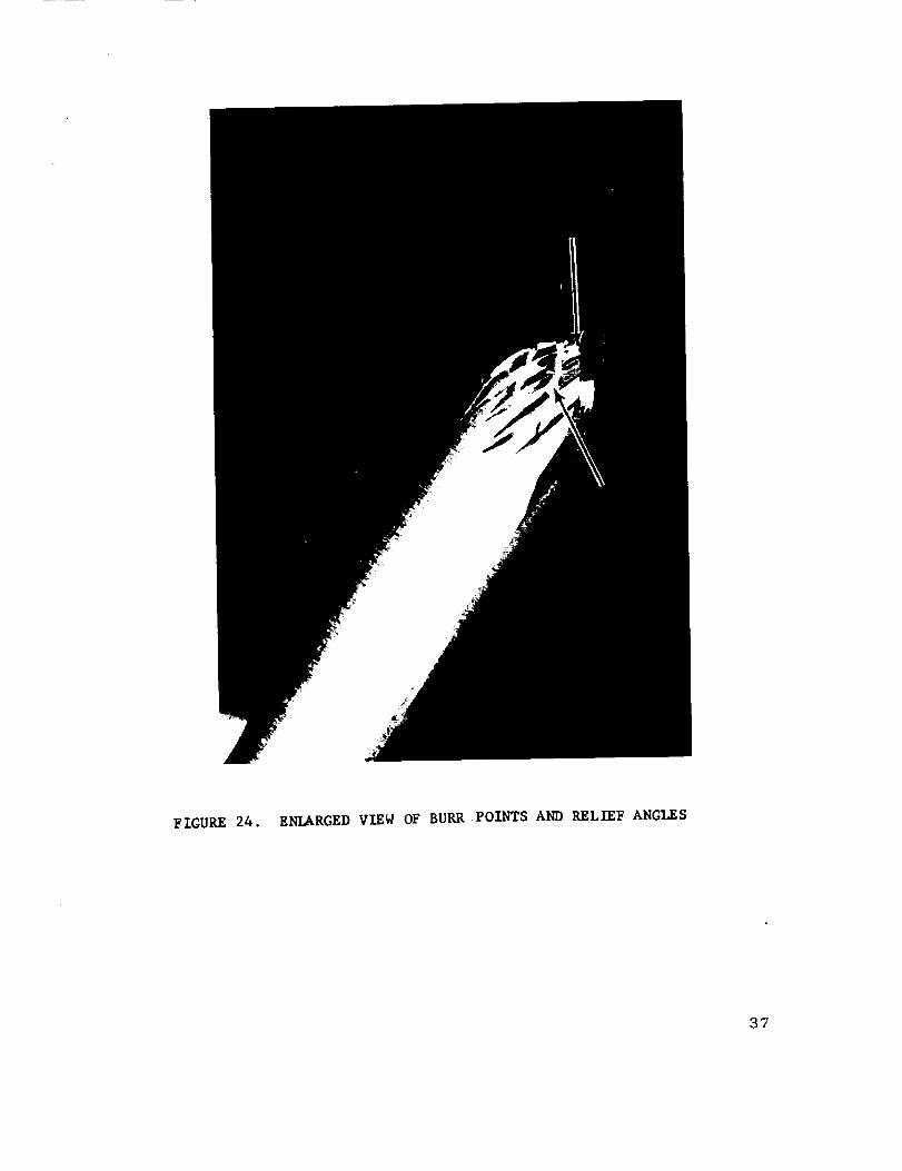
FIGURE 24. ENLARGED VIEW OF BURR POINTS AND RELIEF ANGLES
37

FIGURE 25. ENLARGED VIEW OF PRII_RY CUTTING EDGE AND LENGTH AND
DEPTH OF GASH FOR CROSS-OVER OF POINT
38

FIGURE26. ENLARGEDVIEW OF ANGLES OF BURR-DRIJ_L POINTS, PRIMARY
CUTTING EDGE AND ANGLE OF RELIEF OF PRIORY LAND
39

The adoption of these inspection procedures
has resulted in the elimination from production use of all drills having
er,y tendency to fracture. Since these rigid inspection procedures
were established, the production shop has been able to drill
several hundred acceptable holes per drill before regrinding was
necessary.
f. Shop Operation. The standard shop opera-
ting procedure for drilling holes is as follows:
(l) _Handle carbide drills with care to avoid
accidental dulling. Protect by storing in individual containers.
Segregate dull drills from sharp ones. Avoid dropping drills onhardened surfaces.
(2) _ Select the drill diameter 0.002 inch
under the required finished hole diameter to allow for the subse-
quent chemical etching.
(3) Install the drill in the spindle chuck,
and set the micro depth stop to prevent accidentally drilling into
the _ig or table.
(4) Exercise care to avoid misaligning the
drill in the hardened steel drill bushing when locating the hole
under the spindle.
(5) Test drill five or more holes in scrap
pieces of beryllium to check the drill grind, hole diameter, finish,
et_., before drilling a production piece.
(6) Stop frequently and examine the drill
for dulling and/or chipping on cutting edges.
(7) Start the drilling operation by pressing
the "cycle" button. Hold the bu{ton depressed for rapid traverse.
lqelease the button to stop the rapid traverse, and to automatically
engage the spindle feed. (Exerclse care to avoid the rapid tra-
versing of the drill point into the work. )
(8) DO NOT use coolants in drilling opera-tions.
4O

(9) The spindle will retract automatically
when it reaches the preset depth of cut and trips the microswitch.
In case of any malfunction, press the red "l_etract 't button, and
the drill will be withdrawn immediately from the work.
(10) After drilling, deburr the holes by
wet or dry sanding, or by chamfering the hole with a carbide
countersinking tool.
g. Hole Location and Bushings. In most drill
_igs, the hole location is accomplished by means of pressed-in
hardened steel inserts and slip bushings. The axis of rotation
must be aligned perpendicular to the _Drkpiece to avoid side stresses.
Because of the abrasive character of beryllium, even hardened
drill bushings are subject to wear and must be replaced period-
ically to maintain accurate hole location.
h. Tool Proving and Maintenance. ]Due to the
abrasive characteristics of beryllium, the use of standard pro-
cedures for the initial proving and routine maintenance of tooling
is mandatory. It is recommended that the fabrication of the first
production pieces on a new tool be witnessed by the tool designer.
The existence of any slight dimensional deviations, within the
allowable tolerances, can be noted and recorded. Periodic in-
spections at regular intervals, based on past experience and wear
records, should be made. Any dimensional changes should be
recorded and any necessary repairs should be made. Iqigid
conformance with such procedures will preclude most, if not all,
re iections due to tooling error.
4. Failure Analysis. In spite of the development of
the previously described "burr" type drill and the rigid drilling
and inspection procedures, drilling failures still may occur. There-
fore, additional holes were drilled incorrectly to intentionally cause
failure in one or more of the three basic modes which are: radial
cracking, internal delamination, and spalling. For comparison, a
correctly drilled hole is illustrated in Figures 27, 28, and 29.
The relative quality of the surface finish of the
hole edge, and of the "as-received" material, is graphically
shown in Figures 27 and 28. The absence of burring and the
presence of only minute irregularities, which are removed during
the subsequent etching operation, should be noted. A description
41

FIGURE 27. CORRECTLY DRILLED HOLE USING RECOI_IENDED PROCEDURES.
EXIT SIDE (UNETCHED)
•91.-- HOLESURFACE
FIGURE 28.
(85X)
CRO_5-SECTION THROUGH GOOD HOLE USING RECOMMENDEDPROCEDURES (UNETCHED)
42

-_I-XOLE
-_ HOLE
SURFACE
FIGURE 29. CROSS-SECTION THRO_G_ GOOD HOLE - MINOR TWINNING
EVIDENT (UNETCHED)
43

of each type of defect, and its probable cause, is presented asfollows :
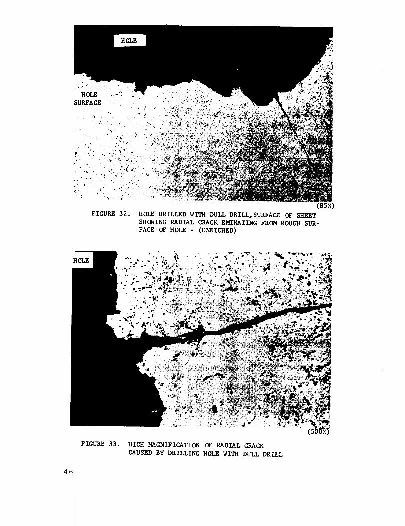
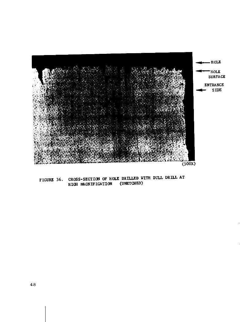
A radial crack is a surface crack which extends
outward from the hole. Figures 30, 31, 32, and 33 illustra_e this
type of defect. This type of failure usually is located on the (exit)i
surface, opposite the drill feeding force, and is the result of the
workpiece yielding to this force. In order to deliberately produce
this defect, a dull drill and excessive feeding force were used.
The surface condition of the resulting hole is illustrated in Figures
34, 35, and 36. Reducing the feed rate, increasing the drill
speed (rpm), using a sharp drill, and providing the proper firm
support for the workpiece usually will correct this condition.
Internal delamination is the designation for inter-
granular separation along basal planes, and, therefore, is in the
plane of the material. Figures 6, 37, and 38 illustrate this type
of defect. Such cracks usually are the result of using either an
extremely dull drill or one with a broken cutting lip. Either type
of drill generates side pressure through chip compaction. Repeated
deflections of the workpiece also can result in this type of defect.
Again, using sharp drills and providing the proper firm support
for the workpiece will prevent this condition.
The term spalling refers to the flaking or crack-
ing-out of the metal around the periphery of the hole on the exit
surface of the workpiece. Figures 39, 40, and 41 illustrate this
type of defect. When the drill "breaks through" the workpiece,
the resistance to the drill feeding force is suddenly relieved and,
unless the drillin_ force also is quickly decreaSed, the drill will
surge through the workpiece and cause spalling of the hole. This
defect can be avoided by the proper use of the tornetic control
system.
E. ABRASIVE WHEEL CUTTING
1. ,Pre.sent ,Capability'. The cutting of beryllium
by means of an abrasive wheel is a relatively long-established
and well-qualified production method. It is the preferred method
for making straight-edge cuts whenever the workpiece configura-
tion will permit the necessary approach and over-travel required
for the circular wheel. A typical example of the newly acquired
44

FIGURE 30. HOLE DRILLED WITH DULL DRILL SHOWING RADIAL
CRACKING (UNETCHED)
(1ox)
FIGURE 31.
(1ox)
HOLE DRILLED WITH DULL DRILL SHOWING RADIAL CRACKING
AND BRIDGING FROM HOLE TO HOLE
45
HOLE ....'_
SURFACE
FIGURE 32.
(85x)
HOLE DRILLED WZ_ DULL DRZ_,SUm_ACE OF S_EZTS_O_ING RADIAL CRACKZm_TZNG FROMROU_ SUR-FACE OF HOLE - (U_TC_ED)
HOLE
FIGURE 33. HIGH MAGNIFICATION OF RADIAL CRACK
CAUSED BY DRILLING BOLE WITH DULL DRILL
4G

EXIT SIDE -q_ ROLE
HOLE
SURFACE
FIGURE 34. CROSS-SECTION OF HOLE DRILLED WITH DULL
DRILL (UNETCHED)
(85)
EXIT
S IDE
FIGURE 35.
°
(5oox)
CROSS-SECTION OF HOLE DRILLED WITH DULL DRILL
SHOWING SPALLED EDGE (UNETCHED)
-._I-_IOLE
._i_ OLESURFACE
47
HOLE
I_OLE
SURFACE
ENTRANCE
SIDE
(5oox)
FIGURE 36. CROSS-SECTION OF HOLE DRILLED WITH DULL DRILL AT
lilG_l_GNIF ICATION (UNETC_ED)
48

(lox)
FIGURE 37. HOLE DRILLED WITH IMPROPERLY SHARPENED DRILL.
NOTE HKAV_ BURR ON EXIT SIDE _UNETCHED)
FIGURE 38. CROSS-SECTION THROUGH HOLE DRILLED WITH
IMPROPERLY SHARPENED DRILL (UNETCHED)
HOLE
HOLE
SURFACE
(85x)
49
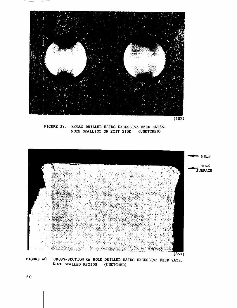
FIGURE 39. HOLES DRILLED USING EXCESSIVE FEED RATES.
NOTE SPALLING ON EXIT SIDE (UNETCHED)
(tOE)
(85x)FIGURE 40. CROSS-SECTION OF HOLE DRILLED USING EXCESSIVE FEED RATE.
NOTE SPALLED REGION (UNETCBED)
HOLE
HOLE
SURFACE
50

HOLE
HOLESURFACE
FIGURE41.
• o "_
C5oox)
CROSS-SECTION OF ttOLE DRILLED AT EXCESSIVE FEED RATE,NOTE CHIPPING ON FLAT PORTION OF HOLE SURFACE (UNETCHED)
51

equipment for the cutting of beryllium is the large capacity precision
abrasive saw illustrated in Figure 42.
.An examination of the following specifications reveals
the extensive capabilities of this saw.
a. Capacity - Sheet and plate up to 2.0-inches
thick; 96-inches wide and infinite length.
b0 Traverse - Feed rate of 0.50 to 0.200-
inches per minutes (ipm); rapid traverse of 150 ipm.
c. Vertical Adjustment- 4 inches
d. Coolant - 30 gallons per minute at 30 psi.
e, Spindle Speed - Infinitely variable from
2200 to 9000 surface feet per minute - based on 14-inch diameter
wheel.
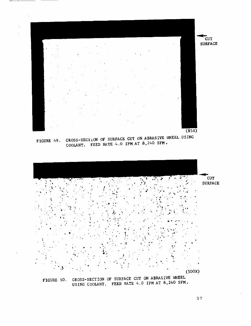
As is typical with abrasive cutting, the resulting
surface finishes are superior to those produced from other pro-
cesses. Figures 43 through 51 illustrate the typical surface
conditions that can be achieved using a rubber bonded abrasive
wheel manufactured by Allison; code Number C120-JRA. The
wheel was operated at a constant speed of 8240 SFM with a
varying feed rate and both with and without coolant.
It may be noted that as the feed rate is increased,
the resulting edge burr is more pronounced although no actual
metallurgical damage is apparent. Standard practice, however,
is to use coolant during cutting to avoid the excessive localized
build-up of heat, which could be cumulative during long cuts and
might result in the development of edge cracks due to the thermal
stresses. The use of coolant also prevents the dispersion of
fine beryllium dust particles. Figures 49 and 50 illustrate the
resulting edge, The abrasive wheel cutting method is used for
trimming the edges of both formed and fiat sheets. Elaborate and
expensive holding devices are seldom required as the cutting
pressures are very low.
2. Projected Areas of Development. The current
procedures have proven to be entirely reliable and satisfactory;
52
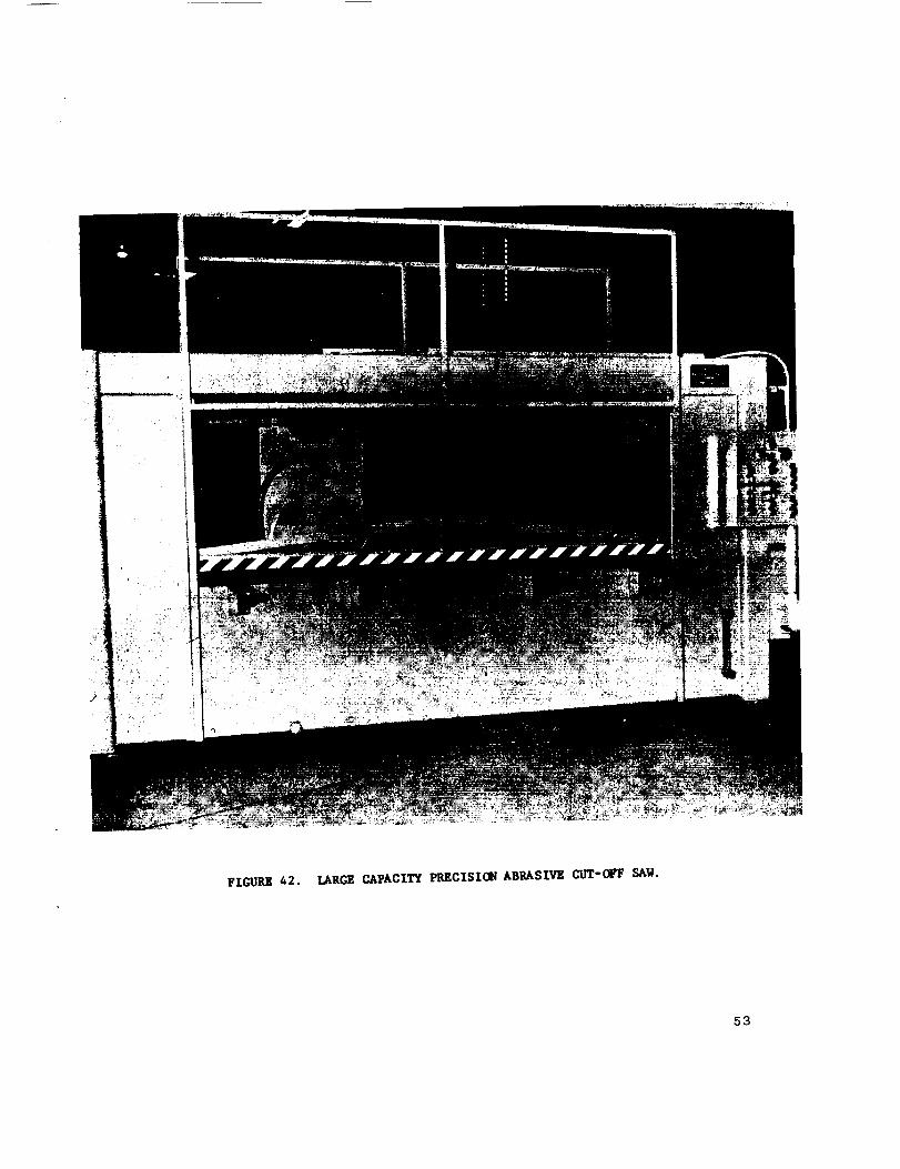
FIGURE 42. LARGE CAPACITY PRECISION ABRASIVE CUT-CFF SAW.!
53

FIGURE 43.
• °
(85x)
CROSS-SECTION OF SURFACE CUT DRY ON ABRASIVE WHEEL •
FEED RATE 4.0 IPM.AT' 8,240 SFM
CUTSURFACE
CUT
SURFACE
FIGURE 44.
(5oox)
CROSS-SECTION OF SURFACE CUT DRY ON ABRASIVE WHEEL.
FEED RATE 4.0 IPM AT 8,240 SFM.NOTE LARGE INCLUSION.
54

CUT
SURFACE
FIGURE 45.
(85x)
CROSS-SECTION OF SURFACE CUT DRY ON ABRASIVE WHEEL.
FEED RATE 6.0 IPM AT 8,240 SFM.
(5oox)
FIGURE 46. CROSS-SECTION OF SURFACE CUT DRY ON ABRASIVE WHEEL.
FEED RATE 6.0 IPM AT 8,240 SFM.
55
CUT
SURFACE

CUT
SURFACE
FIGURE 47. CROSS-SECTION OF SURFACE CUT DRY ON ABRASIVE WHEEL°
FEED RATE 7.5 IPM AT 8,240 SFMo
W
(5oox)
FIGURE 48. CROSS-SECTION OF SURFACE CUT DRY ON ABRASIVE WHEEL.
FEED RATE 7.5 IPM at 8,240 SFM.
56
CUT
SURFACE
FIGURE 49.
(85x)
CROSS-SECTION OF SURFACE CUT ON ABRASIVE WHEEL USINGCOOLANT. FEED RATE 4.0 IPM AT 8,240 SFM.
FIGURE 50.
CUT
SURFACE
5?

FIGURE 51. ABRASIVE WHEEL CUT SURFACE - LIGHTLY POLISHED.
(85X)
58
!
FIGURE 52.ROUTER CUT SURFACE - LIGHTLY POLISHED.
(ssx)

no major process advancement in abrasive wheel cutting is
required or anticipated for the present or projected production
needs.
3. Current Procedure.
a. Safety and ]Environmental Control. Because
the action of abrasive cutting produces very fine beryllium particles
which tend to become airborne, similar to those produced by
grinding, the maintenance of rigid safety precautions is mandatory.
All abrasive cutting is accomplished in
approved facilities located within the beryllium sheet metal fabrication
shop. The machine is contained within a transparent enclosure
equipped with high velocity vacuum hoses to capture any beryllium
particles. In addition, the large capacity coolant system not only
cools the work, but also flushes all cutting residue through a
separator/filter system.
b. Shop Operation. Prior to starting any cut-
ting operation, the abrasive wheel is always carefully inspected
for indications of chipping, cracking, and edge wear. The work-
piece then is placed in position, clamped in place, and the necessary
height adjustment is made to insure the proper wheel penetration
through the workpiece. The sliding transparent doors of the en-
closure are closed, the vacuum and coolant systems and the wheel
power are activated, and the abrasive wheel is advanced into the
workpiece at a predetermined feed rate. All the controls are
actuated from a central panel located outside the enclosure con-
veniently accessible to the operator.
F. I_OU TI NG
1. Present Capability. Although routing is a long-
established and well-qualified production method used for the machin-
ing of a wide variety of internal cutouts and edge profiles in many
materials, the routing of beryllium sheet is a recently developed
process which currently is being utilized for the production of
skin panels and related parts of a space vehicle structure. Figure
54 illustrates both the special and standard cut carbide routed bits
that have been developed for this purpose. The two basic types
are the multi-fluted spiral cut and the standard diamond (burr}
59

pattern. Both types are available in either the ball or the flat
nose configuration.
To insure successful routing, rigid and sub-
stantial fixtures must" be used to reduce the impact loading to the
minimum, and to provide constant loading of the beryllium during
the routing operations.
lqelatively inexpensive "router block" tooling is
used to guide the workpiece relative to the stationary router
spindle. Manual control of the cutter feed is being used at the
present time as illustrated in Figure 53.
2. P ro_ected Areas of Development. The availability
of larger sheets and plates is anticipated and since it is easier
to manipulate a small router head than a large workpiece, proposed
designs for advanced routing equipment are taking the form of
either bridge or gantry type machine tools utilizing either numerical
or cam controls. In addition, longer tool life and improved cutting
efficiency can be attained only by eliminating the variable feed re-
sulting from manual manipulation of either the router head or the
workpiece and router block.
3. Current Procedures. Cutouts and edge trimming
are accomplished by routing. /i firmly supported air-driven motor
turning at a free-running speed of 900 - 1000 rpm is used for all
routing operations. The feed rate is varied from 0.5 inch to l
inch per minute, depending upon the gauge of the material. Inter-
nal cutouts are made by slowly plunging the ball nose type of
cutter through the material, _/%en progressing around the periphery
of the cutout as guided by the tooling. The flat nose type of cutter
is used for edge trimming or for making shallow cuts that do not
penetrate completely through the material.
Figures 52 and 56 illustrate typical router cut
edge conditions. It should be noted that the surface damage is
very minor, and that twinning is limited to a very narrow band,
approximately 0.000G-inch deep, which is easily removed during
the required subsequent etching operation.
lqouting has proven to be an efficient and econom-
ical method for producing internal cutouts of irregular shape, and
for external trimming to net dimensional requirements.
6O
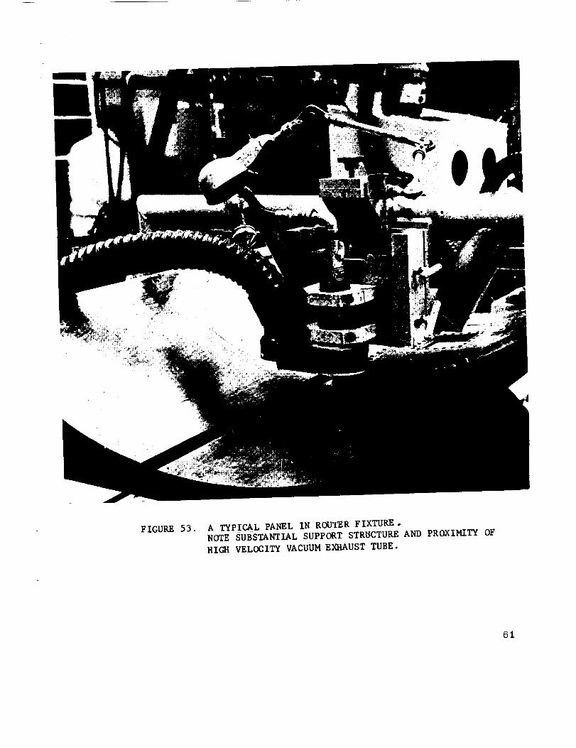
FIGURE 53. A TYPICAL PANEL IN ROUTER FIXTURE .NOTE SUBSTANTIAL SUPPORT STR_CTURE AND PROXIMITY OF
HIGh1 VELOCITY VACUUM EXIIAUST TUBE.
61

A..... B C D
A - SPECIAL SPIRAL _LTI-FLUTED BALL NOSE
B - SPECIAL SPIRAL I_JLTI-FLUTED FLAT NOSE
C - STANDARD CUT (BURR) BALL NOSE
D - STANDARD CUT (BURR) FLAT NOSE
FIGURE 54. TYPES OF CUTTERS USED IN ROUTING
BERYLLIUM SHEET
62

CUTSURFACE
FIGURE 55. CROSS-SECTION OF ROUTER CUT SURFACE.
(85x)
• _'* • .i . :. - * • . *. . _ "
FIGURE 56.
_L* " *
(5oox)
CROSS-SECTION OF ROUTER CUT SURFACE•
ClITSURFACE
63

G. SHEARING
The shearing of beryllium, like piercing or punching,
•has been found to be a most impractical process at roomltempera-
ture. Gross material damage and fracture invariably result.
Shearing at elevated temperatures and shearing while encased
in a protective metal envelope may be feasible. The disadvantages
(time, specialized equipment, cost) of these added complications,
however, appear to outweigh any possible advantage shearing
might conceivably have over abrasive sawing or routing.
The primary advantage of the shearing process is
the very low cost in production manhours per unit. The relatively
high cost of beryllium material, however, makes the quality of
product, and the reliability and repeatability of a production pro-
cess, of far greater economic importance than a minor saving
in manhours. Further investigation, therefore, is not anticipated.
SECrFION IV. Pl_ECISION MACHINING
A. GENERAL
This section describes beryllium metal removal opera-
tions as performed on conventional precision machine tools such
as lathes and milling machines. The workpiece usually will be
machined from vacuum hot-pressed block which possesses some-
what different properties from those possessed by wrought forms
such as sheet, plate and extrusions.
Vacuum hot-pressed blocks are produced by com-
pacing and sintering beryllium powder on a mold at a tempera-
ture of I050°C and a pressure of I00 to 200 psi. The resulting
grain structure is random (isotropic) and, therefore, has less
tendency toward boundary separation or delamination during
machining than the wrought forms which possess oriented (aniso-
tropic) grain structures. Although the mechanical properties
(Ftu and Fry) of the vacuum hot-pressed block are lower than
those of the wrought forms, the machining characteristics are
64

better, i.e., it is less subject to spalling, cracking, and/ordelaminatio n.
The relatively high cost of beryllium material has
made the utilization of numerically controlled equipment particularly
advantageous. The control tapes, fixtures, and cutting tools can
be "tried out" and "proven" on the machine using inexpensive
material for workpiece simulation. /x_fter the machine settings
have been verified, the beryllium workpieces can be machined
with confidence.
As more and more beryllium is used in ever-
widening hardware applications, its cost undoubtedly will decrease.
As this occurs, the manhour fabrication costs will become pro-
portionally greater, and the development of ways and means for
increasing the productivity of the precision machine tools will
become increasingly important.
t3. TUI:_NING
1. Present .Capabilit)r. The precision turning
of beryllium on engine and turret lathes, and on vertical boring
mills is an established and well-qualified fabrication method.
Missile re-entry heat shields, frustums, and cones are machined
by turning. A_ cutting speed of 250 surface feet per minute is
used without coolant or an immediate enclosure. A close-capture,
high-volume vacuum exhaust tube, located adjacent to the cutting
tool, is used for the disposal of the chips. Excellent material
removal rates are achieved using mechanically held carbide insert
tool bits, and conventional work holding methods (chucking with
soft formed _aws, etc.) frequently can be utilized to eliminate the
need for expensive special tooling. Completely crack-free machined
surfaces, wi_h a 32 I_MS finish, are consistently attainable in pro-
duction operations. However, both the machine and the "setup"
must be rigid, and the overhang of the workpiece and of the tool
must be minimum.
2. P ro)ected Development. The present
machining (turning) procedures satisfy all current production
65
requirements. Approximately 400 surface feet per minute appears
to be the best cutting speed for machining (turning) beryllium.
However, at this speed, an enclosure must be used to contain
the fine dust-like chips, lqeasonable tool life has been attained
with ceramic too] inserts used at speeds up to 800 surface feet
per minute. Thus, high speed production turning methods have
been proven feasible, and probably will be utilized in future
facilitie s.
3. Current Procedures. At cutting speeds
up to 250 surface feet per minute, a close-capture, high-volume,
3-inch diameter vacuum exhaust tube is entirely adequate for the
se/e control of the beryllium chips. However, at higher surface
speeds, an enclosure must be _/sed to contain the fine dust.
The cutting speed, feed, and depth of cut
are interrelated with the cutting tool material and geometry.
Slower cutting speeds, with coarser feeds and deeper cuts,
normally are used for roughing cuts since more material can be
removed per minute for a given tool life. This can be achieved
only by using carbide or ceramic cutting edges. Carbide,
expecially grade C-2 (Carboloy 883, Kennametal K-6, e_c.),
is the most satisfactory material for rough curbing. Because of
their lower cost, availability, and dimensional repeatability,
mechanically held indexible carbide inserts are preferred over
brazed-on tips. (A new cutting insert can be indexed into position
within 0.002 inch of the setting of the previous insert.) Positive
side rake holders, with square and triangular inserts, are re-
commended for general cutting. A depth of cut up to 0. 100 inch,
with a feed up to 0.020 inch per revolution, can be used if th4
material is sufficiently thick to resist cracking.
Clamp-in type ceramic inserts (Carboloy,
grade 0.30 cemented aluminum oxide), with negative rake, are
superior to the carbides for finishing cuts or for light continuous
cutting because they resist the formation of a built-up cutting edge.
A side-edge cutting angle is satisfactory. The necessity for
changing tools when changing from rough to finish cutting tends
to deter their use. The cutting speed may vary from 150 to
more than 400 surface feet per minute, with khe depth of cut, and
the fixed rate per revolution, ranging from 0.002 to 0.020 inch
and from 0.004 to 0.012 inch, respectively. In general shop
66
practice, an extremely light depth of cut and a fine feed are used
as the required dimensions and surface finish are approached.
Although care must be exercised in turning thin-walled or un-
supported workpieces, surface cracks or workpiece breakage
have not been serious production problems.
C. MILLINO
1. Present Capabilit_r. Because of the low ductility
of beryllium at room temperature, it was believed, initially, that
the shock caused by the milling cutter teeth entering and leaving the
workpiece might prevent milling from ever becoming an appropriate
machining process for beryllium. However, experience in milling
beryllium has shown that such is not the case, and today a wide
variety of complex configurations are being shccessfully milled on
convenlional machihes from all the forms of beryllium material:
sheet, plate, extrusions, forgings, and hot-pressed block.
"Climb" or "down" milling is used for most
machining operations as opposed to "conventional milling. I' Car-
bide cutting tools, usually without coolant, are used. Two to
three hundred cubic inches of material can be removed before
regrinding the cutter is necessary. Surface finishes of 125 IqMS
or better are readily attainable.
2. Projected Development. The present milling
procedures are adequate for all forseeable production requirements;
no significant developments are anticipated. However, it is antici-
pared that the application of numerical control may be particularly
advantageous. The current success of milling operations is largely
dependent upon the individual skill and care exercised by the machine
opera_ors, and therefore, is subject to human errors.
3. Current Procedures. Conventional milling
machines are being used for machining beryllium. The machine
and the set-up must be extremely rigid to avoid spalling. Be-
cause of the abrasive quality of beryllium, the machine ways and
columns are subject to accelerated wear and, therefore, should
be wet-wiped frequently, k4ost milling operations are performed
without coolants using a close-capture, high-volume vacuum exhaust
tube to dispose of the chips. When a cutting fluid is required,
water-soluble oil may be used. Cutting fluids, which are used
67

for machining beryllium, should be stored in suitable containers,
and should be disposed of only as approved by the appropriate
safety personnel. Beryllium chips, which have been wet -with
cutting fluid, have a low salvage value and should be kept segre-
gated from clean beryllium scrap.
"Climb" or "down" milling should be used when-
ever possible as this procedure will prevent spalling at the point
the cutter leaves the work. When the conventional milling pro-
cedure must be used, a backup block should be used in the area
where the cutter leaves the work. A piece of scrap beryllium
is preferred to a_void the contamination of the chips. However, a
piece of mild steel can be used as a backup; the mild steel chips
can be readily separated from the beryllium chips by the use of
a magnet.
Carbide cutting edges are recommended for all
milling operations. Grade C-I (Carboloy 44A or equivalent) is
recommended for the rough cuts; grade C-2 (Carboloy 883 or
equivalent) is recommended for the finishing cuts. Various types
of milling cutters and bodies are being used successfully, e.g.,
inserted indexible carbide blades, brazed-on carbide tips, and
solid carbide. In all cases, however, both the axial and the
radial rake angles must be positive. Angles of 5 to 7 degrees
are recommended, with primary and secondary clearances of 3 to
5 and 7 to 9 degrees respectively. The recommended cutter
corner radius is one-fourth of an inch.
Beryllium has been milled satisfactorily at cutting
speeds above 400 surface feet per minute. However, the prob-
lems and inconvenience involved in safely containing the fine chips
and dust usually result in the use of slower cuffing speeds - under
300 surface feet per minute.
A light feed per tooth of 0.002 inch per revolution,
and a light depth of cut of less than O. 100 inch normally will result
in the production of a surface finish of 100 IRMS or better.
68

S ECTION V. ELECTRICAL DISCHARGE
MACHINING (EDM)
A. GENERAL
Under certain conditions, beryllium cross-rolled sheet
is difficult to machine without incurring material damage because
of its anisotropio grain structure. Therefore, the Electrical
Discharge Machining process was included in this program in
order to evaluate its applicability for machining cross-rolled sheet,
Electrical Discharge Machining may be defined as the
process of removing metal by means of electrical discharges in
the presence of a dielectric'. This is not a new or revolutionary
process: it has been utilized by industry for many years. The
principal advantages of the process are as follows:
1. The ease with which complex cavities or cuts
can be made in otherwise difficult-to-machine materials.
2. The cutting tools (electrodes) can be fabricated
from inexpensive materials, and will reproduce their configurations
faithfully.
3. "Gang" drilling is applicable to many production
operations, permitting the simultaneous cutting of holes and/or
irregular shapes.
4. Freedom from defects and fine finishes are
easily attainable, which can be duplicated only by other much
more costly machining processes.
B. OPERATING PRINCIPLES
Electrical Discharge Machining (EDM) utilizes t_he
eroding action of a short duration electric arc, or spark, in cut-
ting or machining the workplece. This arc is generated between
the cutting tool (electrode) and the work; both items, therefore,
must be electrically conductive.
69

The rate of material removal is dependent upon the
electrical current flow (amperes}. In order to control the cut-
ring action of the spark, the spark duration is limited by the amount
of energy delivered to the workpiece through the power supply.
The machine curre_nt flow consists of a series of
sparks, each precisely controlled in energy content. The machin-
ing rate, then, is proportional to the average current through the
spark gap. The lower frequency of the pulsating DC current,
therefore, creates a larger portion of vaporized material at the
point of impact. The crater thus created results in the production
of a surface finish from 300 to 500 micro-inches. At low fre-
quencies, a temperature approaching 700001 ? is generated in the
workpiece. The dielectric oil therefore, serves the dual purpose
of cooling the work and preventing the shorting of the circuit by
removing the material particles from the workpiece-electrode en-
velope.
The frequencies obtained at tap switch position 1
through 11 are included in Table III. It may be noted that each
tap switch (except 9, 10, and 11) in ascending order provides
a frequency approximately double that available at the previous
setting. Thus, it would appear in each case, that an equivalent
surface finish could be provided at twice the metal removal rate.
Figure 58 illustrates the effect of tap switch setting
on surface finish. In example (A), one electrical discharge
contains a certain amount of energy and will remove a given
volume of material. Example (]B) has the same average current
flowing between the electrode and the work and the volume of
material removed is the same in both cases. However, the
number of discharges per second, or the frequency, has been
doubled in example (B) , i.e., the gap current has been divided
into two discharges and the resulting surface finish will be im-
proved. Examples (C) and (D) show the effect of increasing
the frequency to four and eight discharges per second respectively.
In each case, the total current was unchanged, and the total
volume of material removed is the same. The surface finish,
however, is improved with each increase in frequency.
7O

FIGURE 57. CINCINNATI MODEL 24A31 ELECTRICAL DISCHARGE
MACHINE WITH ELOX NPS D-60 POWER SUPPLY
7i

°i
°i
A
_v
72

C. PRESENT CAPABILITY
A typical machine, Cincinnati No. 2 lqam "Electro
Jet, " illustrated in Figure 57, is equipped with its own high-
velocity vacuum system tO remove vapors from the work area.
The fine po%vder produced during the e/_ctrical erosion process
is suspended and carried a_vay in the dielectric I fluid through a
fine microfilter. This arrangement, in conjunction _rith the con-
stant room monitoring, adequately meets all safety and hygiene
requirements.
In addition, the machine is equipped with a rotating
electrode capability for precision hole cutting. The ram platen
is 12 inches by 18 inches and has a vertical travel limit of 12
inches. This machine has no provision for lateral and/or longi-
tudinal table adjustments. Only vertical or plunge cutting can be
accomplished without special tooling.
D. PR, OJECTED DEVELOPMENT
The ]Electrical Discharge Machining process has
been used for miscellaneous "straight line" cutting and for drilling
extremely fine holes. Tensile test specimens, being programmed
for this machine (rather than the conventional "Tensilcut" router
approach -- not described in this report) should provide more
accurate and consistent test results. Additional development work
is required to support any new specific applications.
E. PROCESS EVALUATION
In order to evaluate the Electrical Discharge Machin-
ing process, a series of holes was cut in a strip of 0.062-inch
beryllium sheet material. The beryllium sheet, the test coupons,
and the electrodes are illustrated in Figure 59. The electrodes
were turned from brass tubing. The outside and inside diameters
of the roughing and finishing electrodes were 1.330 inches OR
and 1.280 inches ID; and 1.340 inches OR and 1.280 inches
ID , respectively
73

i _i!i _ii_ ¸
, , i_ • i_
z
_z
_8
u-_
74

FIGURE 60. CROSS-SECTION OF EDM ROUGHING CUT
(83x).
f •
p
"4
,°
..
• .o
. O
_ ° °
e
a
%-
FIGURE 61. CROSS-SECTION OF EDM ROUGHING CUT
76

The beryllium strip was clamped to an aluminum back-
up block and the roughing electrode was mounted in the rotatable
spindle. The tap switch was set on No. 5, which provided an
operating frequency of 32,000 cycles per second at 4 Mfd, 7.0
amperes, and 74.0 volts.
All the holes were initially "roughed out t' in 7 minutes
at these settings at a metal removal rate of 1.82 cubic inches per
hour. Figures G0 and 61 illustrate the resulting finish. The
relatively uneven cut and the frequency of microcracks in the form
of basal plane cleavage should be noted.
The roughing electrode was replaced by the finishing
electrode and 11 of the 12 holes were "finish cut" at the tap
switch settings shown in Table IV.
1. Specimen Preparation. A small wedge section
was removed from each hole edge; mounted, ground and polishedfor microscopic examination in order to determine the effect of
EDM machining at various rates on the material physical structure.
Specimen preparation provides a true cross-
section of the hole and is therefore normal to the plane of the
sheet intercepting the EDM cut surface. No etching was done
prior to mounting for metallographic examination in order to
preserve the true condition of the hole surface as cut.
manner:All specimens were prepared in the following
a. Mounting - The specimen was mounted in
such a manner as to expose the above section surface with the
EDM cut constituting one edge of the specimen. The specimen
was mounted in green bakelite.
b. Grinding - The specimen was ground in
beryllium contamination hoods on successively finer grit silicon
carbide abrasive papers from 240 grit to 600 grit.
c. Coarse Polishing - The samples were
coarse polished on a 1 micron diamond paste impregnated
slipper satin covered polishing lap, using a multiple jig-dop device toeliminate excessive labor.
75

M
o o
0 0 0 0 0 0 0 0
0 u'm 0 0 0 0 0 0
OJ
77

d. Final Polishing - Final polishing was per-
formed on a proprietary automatic polisher of the rotational
variety using a maximum load of 250 grams per sample for a
minimum period of time (based upon inspection) to provide an
adequate surface with a minimum amount of relief and rounding of
the EDM cut edge. The polishing was performed in a contained
slurrey of "Cer-Cer" metallographic polishing abrasive plus aqueous
solutions of N_0H and Cr03 added independently to produce an
approximate pH of 9. This method produces a buffered basic
solution to control corrosion of the beryllium. A "rhicrocloth" was
used in this operation and was isolated from the metallic polishing
lap by a layer of lucite to prevent galvanic action.
e. Examination - No further preparation or
etching was required. The specimens were photographed at
magnifications low enough to include the entire 1EDM cut edge
(i.e., the cross-sectional thickness of the sheet) and at a higher
compromise magnification to show a representative edge and
structural details. The magnifications chosen were 83X and 500X,
respectively, for 5 by 7-inch plates. The type of illumination
chosen was t'bright field H reflected light since the examination
involved the evaluation of surface contours and laminations pro-
duced by the cutting rather than crystalline deformation resulting
in twinning etc., which would require polarized illumination.
2. Specimen ]Evaluation. /Even a casual analysis
of Table IV and Figures 62 through 71, inclusive, quickly
reveals the direct relationship of the current density, discharge
frequency, surface finish, and metal removal rate. A closer
analysis reveals the severe intergranular cleavage resulting
from the rapid cutting rates, which is unacceptable for beryllium,
and the very minor damage incurred at the higher frequency, and
slower cutting ranges. However, at the extremely high frequencies,
the metal removal rates are unacceptably low for production opera-
tions.
The results of this investigation then can be
sulnmarized as follows:
a. Tap switch seLtings 1 through 4, inclusive,
should be used only for rough cuts, or 'when the tensile, bearing,
or fatigue loads are low.
78

b
FIGURE 62. CROSS-SECTION OF EDM FINISH CUT AT 2,000 CPS.
METAL REMOVAL RATE I. 140 CU. IN./HR.
g
J
(83x)
|,
FIGURE 63.
. °
CROSS-SECTION OF EDM FINISH CUT AT 2,000 CPS.
METAL REMOVAL RATE I. 140 CU. IN./HR.
(500X)
79

FIGURE 64. CROSS-SECTION OF EDM FINISH CUT AT 8,000 CPS.
METAL REMOVAL RATE 0.38 CU. IN./ HR.
(83x)
80FIGURE 65. CROSS-SECTION OF EDM FINISH CUT AT 8,000 CPS.
METAL REMOVAL RATE 0.38 CU. IN./HR.
(5oox)

FIGURE 66. CROSS-SECTION OF EDM FINISH CUT AT 130,000 CPS.
METAL REMOVAL RATE 0.285 CU. IN./HR.
(83x)
!
o
FIGURE 67.
o
u
I•i o
°¢
6
(5oox)
CROSS-SECTION OF EDM FINISH CUT AT 130,000 CPS.
METAL REMOVAL RATE 0.285 CU. IN/HR.
8i
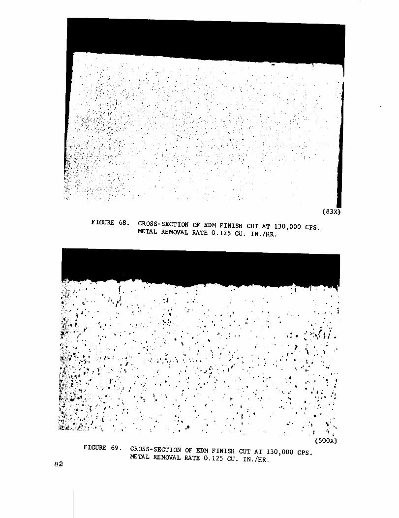
FIGURE 68. CROSS-SECTION OF W.DM FINISH CUT AT 130,000 CPS.
METAL REMOVAL RATE O. 125 CU. IN./HK.
(83X)
FIGURE 69. CROSS-SECTION OF EDM FINISH CUT AT 130,000 CPS.
METAL REMOVAL KATE 0. 125 CU. IN./HR.
82
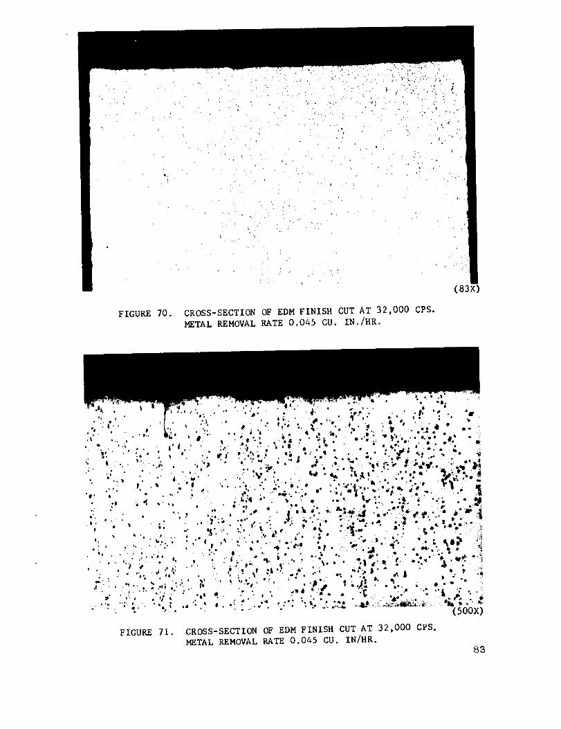
FIGURE 70. CROSS-SECTION OF EDM FINISH CUT AT 32,000 CPS.
METAL REMOVAL RATE 0.045 CU. IN./HR.
(83X)
" (5oox)
FIGURE 71. CROSS-SECTION OF EDM FINISH CUT AT 32,000 CPS.
METAL REMOVAL RATE 0.045 CU. IN/HR.
83
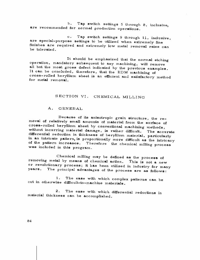
b. Tap switch settings 5 through 8, inclusive,
are recommended for normal production operations.
c. Tap switch settings 9 through 11, inclusive,
are special-purpose settings to be utilized when extremely fine
finishes are required and extremely low metal removal rates can
be tolerated.
It should be emphasized that the normal etching
operation, mandatory subsequent to any machining, will remove
all but the most gross defect indicated by the previous examples.
It can be concluded, therefore, that the EDM machining of
cross-rolled beryllium sheet is an efficient and satisfactory method
for metal removal.
SECTION VI. CHEMICAL MILLING
A. GENERAL
Because of its anisotropic grain structure, the re-
moval of relatively small amounts of material from the surface of
cross-rolled beryllium sheet by conventiofial machining methods,
without incurring material damage, is rather difficult. The accurate
di_erential reduction in thickness of beryllium material, particularly
in an intricate pattern, is proportionally more difficult as the intricacy
of the pattern increases. Therefore the chemical milling process
was included in this program.
Chemical milling may be defined as the process of
removing rnet_l by means of chemical action. This is not a new
or revolutionary process; it has been utilized in industry for many
years. The principal advantages of the process are as follows:
1. The ease with which complex patterns can be
cut in otherwise difficult-to-machine materials.
2. The ease with which differential reductions in
material thickness can be accomplished.
84

3. With accurate temperature and process controls,
close tolerances can be attained.
4. Freedom from defects and good finishes are
easily attainable.
B. PRESENT CAPABILITY
A typical facility for chemical milling and etching of
beryllium consists of tanks and equipment as shown in Figure 72.
A tolerance of 0.002 inch is routinely attained during production
operations in this type of facility. A typical facility utilizing the
c'hemical milling process is used in the production of "Agena"
structural panels. Additional development is required to support
a specific application.
C. PROCESS EVALUATION
In order to evaluate the chemical milling process and
to increase the knowledge of the process as applied to beryllium,
test specimens were chemically milled in four different etchants;
Sulfuric Acid, Ammonium Bifluoride, Nitric Acid-Hydrofluoric
Acid, and Sulfuric Acid-Phosphoric Acid.
In addition, a chemical polishing bath was used on
specimens 20 and 22, following the chemical milling operation,
to evaluate the "smoothing" effect on the chemically milled surface.
The composition of this b_th was as follows:
Chromic Acid 210 gm
Water 350 ml
Sulfuric Acid (95%) 82 ml
Phosphoric Acid (85%) 1500 ml
85

86
o_
E_
P-.1
c_f_
r_
X

Test specimens, approximately 3 inches by 1.75
inches, were cut from the same sheet of 0. 125-inch thick beryl-
lium. The specimens were coated with approximately 0.008 inch
of ttTurcoform Maskant 7A," a neoprene base material, and a
"window, 11 approximately 1.8 inches by I inch, was made in the
mask on one side of the specimens to expose the beryllium to the
action of the etchant. A small "window," approximately 0.500
inch by 0.500 inch, was made in the mask on the other side of
the specimen, opposite the center of the large "window, i, to
facilitate the taking of accurate thickness measurements. During
the chemical milling process, this small opening was covered with
0.005-inch thick vinyl tape to prevent chemical action by the
reagent.
All the test specimens were chemically milled in
four liter-glass or polypropylene beakers containing three liters
of etchant. The ratio of bare beryllium surface to the volume
of etchant is included in Table V. The specimens were placed
on the bottom of the beaker with the "window side" up. When
cooling was required to maintain the etchant temperature within
the desired limits, the beaker was placed on a stand in a large
water rinse tank. The thickness of each specimen was measured
with a micrometer, before and s.fter the chemical milling operation.
Profiles of the surface of the "as received" material and of the
chemically milled areas were obtained with a micro-inch "Profi-
corder" (Piloter Type lqLC, Model 1_; Amplicorder Type lqAC,
Model 4) manufactured by the Micrometrical Manufacturing Company
of Ann Arbor, Michigan. In addition, lqMS surface finish data
were taken with a Model 3, Type OC Profilometer, also manu-
factured by the Micrometrical Company. To further aid in the
evaluation of the resulting surface finishes, 18X macrophotographs
were taken of the "as-received" and chemically milled surfaces.
It should be emphasized that any one item of data is
misleading and should not be considered the "whole story." For
example, the surface may be very wavy, i.e., completely un-
acceptable, and yet be quite smooth. The characteristics of the
profile peaks and valleys, whether large or small, sharp or
rounded, and their frequency and spacing all indicate measures of
surface acceptability. The surface of specimen number 8 (Figures
98 and I00) is an excellent example of this combination; the wavy
surface is clearly visible to the unaided eye, the macrophotograph
and the profile record verify the waviness, and yet the surface
87
smoothness is i00 1QMS.
iQepresentative macrophotographs and surface pro-
files are presented in Figures 73 through 100. The data, develop-
ed during the course of this investigation, are summarized in
Table V, and are discussed briefly as follows:
1. Sulfuric Acid. Examination of all of the speci-
mens chemically milled with sulfuric acid solutions revealed slightly
wavy edges, due to the scribing method used in cutting through
the maskant. In all cases, full radii were attained and smooth
removal of material occurred at reasonable rates.
The rate of material removal was found to be
proportional to both the concentration and the temperature of the
sulfuric acid solution. In any case, the solution is highly exother-
sic and both heating and cooling must be provided to control the
temperature of the bath and, thus the etching rate.
The degree of "cratering" appeared to be de-
pendent upon the temperature of the solution. An examination
of specimen number 12 (Figures 74 and 86), chemically milled
at 80°F - 85°F, reveals extensive shallow cratering; specimen
number 21 (Figures 77 and 79), chemically milled at 90°F -
95°F contains only vestiges of the craters visible on specimen
number 12. Increasing the temperature of the solution to 90°F-
105°F very nearly eliminated the "cratering" but did induce some
random pitting. Chemically polishing one of the specimens (No.
22) sufficiently to remove 0.001 inch of material brightened the
surface but did not eradicate the slight pitting.
Because of this cratering effect at the lower
temperatures, a minimum temperature of I00°I _ is recommended.
As previously stated, and as shown in Table V the metal
removal rate is sensitive to both changes in concentration and
temperature. These variables must be closely controlled to pro-
vide a predictable etching rate. Therefore, both heating and
cooling capabilities with good thermostatic control, solution level
control, and frequent solution analyses and replenishment are
necessary to ensure accurate control of the chemical milling
process. Otherwise, dimensional control can be maintained only
by accomplishing the operation in short duration steps combined
with frequent thickness measurements. Under such circumstances,
88

O
8
J _q
v
-i o
_H
w
H_
4J
o
oo_ _
_o_ __
v
O_OOo_OOO,0.,,,o,°
ooooOoOOO
o
_M
0 0 0 0 0 0 0 0 0 0,.ooO.,
0000000000
0
v
89

0 0
8 _ _ 8'_ ,-4
_ C_OJ _ OJ
u'_ 0o _
6 o o 6
Cr_ Or_ O_
CO CO
+ + + 4"
0
8
CO
8
-.I _00 00 0
0 0
c,_ COD- CO
D--.....
=t CO
Q;
0
00
_ m
0 ,"t _
oo_o _
_ _ _ O_ _
_ _-_ C_ U 0,"4
_o__®
9O
the accomplishment of close tolerance work would be very difficult.
It should be noted that the metal removal rate
becomes very high at temperatures slightly above the recommended
operating range, and the heat produced during the reaction with
the beryllium, if not controlled, can easily cause a runaway
reaction.
Although sulfuric acid is a satisfactory reagent for
the chemical milling of beryllium, a residue remains on the sur-
face which must be removed by a subsequent operation. This
residue can be removed by vigorous washing, scrubbing, or,
more easily, by briefly immersing the beryllium in a Nitric acid-
hydrofluoric acid bath and rinsing with water.
2. Ammonium Bifluoride. The radii and edges of
the specimens chemically milled with ammonium bifluoride were
very similar to those attained with the sulfuric acid solutions.
The chemically milled surfaces were textured
in appearance and somewhat rougher than the surfaces chemically
milled with sulfuric acid. There was, however, no evidence of
deep pitting. The chemical polishing of one of the specimens
did brighten the surface, but did not remove its textured appearance.
The lower concentrations, 5 percent and 7.5 percent of ammonium
bifluoride produced some shallow cratering. Figures 82 and 84show this effect.
However, unlike sulfuric acid, the etching rate
of ammonium bifluoride is not highly sensitive to the solution
concentration. The rate, at solution concentrations varying from
10 percent to 20 percent, and within a temperature range of
80°17 - 90°17, is quite constant; between 15 percent and 90 per-
cent, it is relatively insensitive. Under these conditions, the
resulting metal removal rate will be approximately 0.0005 inch
per minute on the exposed material. The rate, however, is very
sensitive to variations in solution temperature; an increase in the
nominal operating temperature from 85°1 ? to 100aF very nearly
doubles the etching rate.
Because of the large amount of heat produced
during the reaction, thermostatically controlled heating and cooling
equipment are required to provide a predictable rate of metal
91
removal.
3. Nitric Aci,d-.Hydrofluoric Acid. The radii and
edges of the specimens chemically milled with the nitric acid-
hydrofluoric acid solution were uneven and evidence of double
radii was visible to the unaided eye. The solution containing
a low percentage of hydrofluoric acid tended to produce deep pits;
the solution containing a high concentration of hydrofluoric acid
produced a "wavy" su_ace. Figures 93 through 96 clearlyillustrate these conditions. This combination of acids either
reacted very slowly or with uncontrollable violence.
4. Sulfuric Acid-Phosphoric Acid. The radii were
uneven and extremely undercut. The 50 percent phosphoric
acid 20 percent sulfuric acid solution caused widespread cratering
as shown in Figures 97 and 99. The high water content solution,
used to chemically mill specimen number 8, caused a hill-and-
valley effect combined with numerous nodules. Figures 99 and
I00 clearly illustrate this condition.
D . RESULTS
Both the sulfuric acid and the ammonium bifluoride
solutions etched the metal smoothly at reasonable rates, although
the rate of metal removal was found to be very dependent upon
the temperature of the solutions. Due to its relative insensitivity
to variations in concentration, compared with sulfuric acid, the
etching rate was much more easily controlled, and more predic-
table with ammonium b_luoride.
The nitric-hydrofluomic acid solution either reacted
very slowly or with uncontrollable violence. Because of
this condition, it is recommended that the use of this reagent
be limited to light etching, the removal of machine induced sur-
face damage, and the removal of the surface residue remainingedter a sulfuric acid chemical milling operation. :No further work
is recommended.
The phosphoric acid-sulfuric acid solution not only
reacted very slowly, but also had a destructive effect on the
surface quality. No further work is recommended.
92
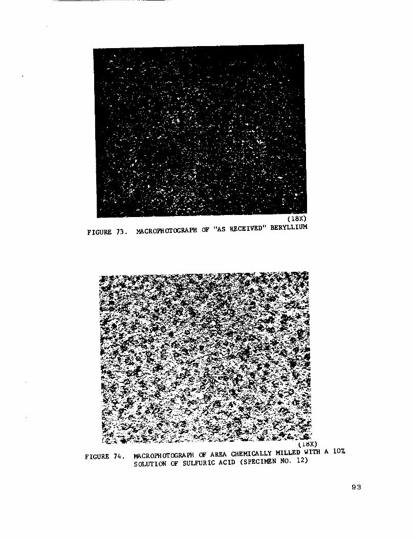
(18x)
FIGURE 73. MACROPHOTOGRAPH OF "AS RECEIVED" BERYLLIUM
FIGURE 74.
_x)
MACROPHOTOGRAPH OF AREA CHEMICALLY MILLED WITH A 107.
SOLUTION OF SULFURIC ACID (SPECIMEN NO. 12)
93

94
|
!
IZl
r_
J_q

o
I",,,,
_d
95

FIGURE 77.
(18x)
MACROPHOTOGRAPH OF AREA CHEMICALLY MILLED
WITH A 10X SOLUTION OF SULFURIC ACID
(SPEClmN NO. 21)
FIGURE 78.
(18x)
MACROPHOTOGRAPttOF AREA (atEMICALLY MILLED WITH
A 7.57. SOLUTION OF SULFURIC ACID (SP_-ClMSN NO. 16)
96
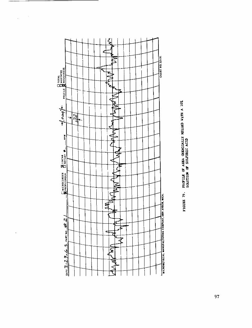
97

@
I i !i
.I
k---- I
_P
P
I
L_II
°
@@
c_a@
i-4
98

FIGURE 81.
(18x)
_CROF_O_OGRA_ OF AREA C_EKIC_LLY M_LLED WITU
A 12.5% SOLUTI(Iq OF SULFURIC ACID (SPECII_N NO. 18)
FIGURE 82.
(18x)
NACROPHOTOGRAPROF AREA CHEMICALLY KILLED WITH A 7.5ZSOLUTION OF AMMONIUM BIFLUORIDE (SPECIMEN NO. 15)
99
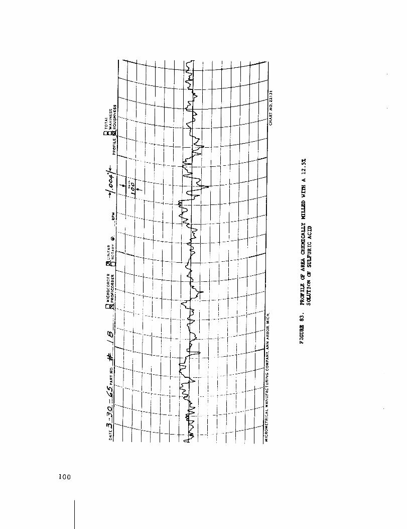
i00

oO
I01

FIGURE 85.(18X)
MACROPHOTOGRAI, H OF AREA CI4EMICALLY MILLED WITH A 107.
SOLUTION OF AMMONIUM BIFLUORIDE (SPECIMEN NO. 6)
FIGURE 86.(18x)
MACROPHOTOGRAPH OF AREA CHEMICALLY MILLED WITH A 157.SOLUTION OF AMMONIUM BIFLUORIDE (SPECIMEN NO. I0)
102


104

FIGURE 89.
(18X)
MACROPIqOTOGRAPH OF AREA OIEMICALLY MILLED WITH A 207o
SOLUTION OF AMMONIUM BIFLUORIDE (SPECIMEN NO. 13)
FIGURE 90.
(18x)
MACROPHOTOGRAPHOF AREA CHEMICALLYMILLEDWITH A 307°SOLUTIONOF AMMONIUMBIFLUORIDE (SPECIMENNO. 23)
105

106
0N
8_

m
D.4 rJ_
I-4
I07

FIGURE93. (18X)I_CROPHOTOGRAPH OF AREA CHEMICALLY MILLED WITH A 45lNITRIC ACID - 3% HYDROFLUORIC ACID SOLUTION (SPECIMENNO. 7)
FIGURE 94.(18x)
MACROPHOTOGRAPH OF AREA CHEMICALLY MILLED WITH A 507.NITRIC ACID - 25% HYDROFLUORIC ACID SOLUTION (SPECIMENNO. 9)
108

I
I
I
i'
I
b----_
I
I
I
Il
I
---T_
I
L •
I
I
I
i
I
i
riI
I
LF
109

Z
o_
ii0

FIGURE 97.
(18x)
14%CROFHOTOGRAPH 0_ AREA CHEMICALLY MILLED WITH A 50%_OSPHORIc ACID - 20% SULfuRIC ACre SOLUTION (SPEClmN
NO. 4)
FIGURE 98.
(lax)
MACROPIlOTOGRAPH O_ AREA CHEMICALLY MILLED WITH A 5 PARTS
(VOL.) PHOSPHORIC ACID - 2 PARTS (VOL.) SULFURIC ACID -
5 PARTS (VOL.) WATER SOLUTION (SPECI_N NO. 8)
iii

¢....J
U
!
M
112

I
I
r._u
°iA
_Ao°
113

SECTION VII. CONCLUSIONS AND RECOMMENDATIONS
Punching or piercing is not recommended for use in pro-
ducing holes in beryllium sheet material. The current drilling
procedures are adequate for all production line requirements.
The current procedures of abrasive wheel cutting have
proven to be entirely reliable and satisfactory.
The present machining (turning) procedures satisfy all
current requirements. Approximately 400 surface feel per minute
appears to be the best cutting speed for machining (turning)
beryllium. However, at this speed, an enclosure must be used
to contain the fine dust-like chips, lqeasonable tool life has been
attained with ceramic tool inserts used at speeds up to 800 sur-
face feet per minute.
The present milling procedures are adequate for all
forseeable requirements; no significant future developments are
anticipated. The current success of milling operations is largely
dependent upon the individual skill and care exercised by the
machine operators, and therefore, is subject to human error.
The application of numerical control will be particularly advanta-
geous.
The Electrical Discharge Machining process has been
used for miscellaneous "straigh[ fine" cutting and for drilling
extremely fine holes. Tensile Lest specimens, being programmed
for this machine, should provide more accurate and consistent
test results. Additional developmental work is required to support
a specific application.
Sulfuric acid, ammonium blfluoride, or both, are accep-
table for chemically milling beryllium. The strength of the solu-
tion, particularly in the case of sulfuric acid, and the level of
the bath should be carefully controlled. Thermostatic control
of the temperature of either solution is mandatory if close tolerance,
predictable results are to be attained. Careful attention to the
details should result in the production of smooth surfaces boundedN
by even edges and radii.
114
APPI_OVAL NASA TM X-53453
THE FAB!RICATION OF BEIqYLLIUM - VOLUME III.
METAL lqEMOVAL TECHNIQUES
The information in this report has been reviewed for
security classification. Review of any information concerning
Department of Defense or Atomic Energy Commission Programs
has been made by the MSFC Security Classificaiion Officer.
This report, in its entirety, has been determined to be
unclassified.
W. A. L
Chief, Methods Development Branch
J. P_)
Chi/eq, Manufacturing lqesearch andTechnology Division
WEI_NER i_ _. KUEI_
Director, Manufacturing Engineering
L abe rate ry
115

DISTRIBUTION
INTERNAL
R-ME-D It2
Mr. Kuers
Mr. Wuenscher
IR-M E-A
M r. Be rge
IR-ME-M
Mr.
Mr,
Mr.
Orr
Schwinghame r
Holland
R-ME-MM
Mr. Wilson
Mr. Brown
1R-ME-MMP
Mr. Schuerer
t%-ME-D
Mr. Eisenhardt
R-ME-P
Mr. P ot_e r
tR-ME-T
Mr. Franklin
1R-ME-TP
Mr. Chesteen
t_ -ME-MW
Mr. Parks
R-P&VE-DIR
D r. Lucas
(5)
!q-P&V E-S
Mr. Kroll
1R-P&VE-SA
Mr. Blumrich
R-P&VE-SAE
Mr. Colley
1R-P &VIE-S AF
Mr. Garret£
I_-P&V 1E-M
Mr. Kingsbu ry
_-P&V E-MM
Mr. Ca£aldo
R-P&VE-MMJ
M:c. Olsen
_-AST_
R,-ASTR-P
Mr, Angele
R-AST_-M
Mr. Boehm
R-TEST-DIR
Mr. Heimburg
MS -IP
MS-IPL (a)
116

DISTRIBUTION (Cont.)
MS-H
HME-P
CC-P
MS-T (6)
AMSMI-RBLD ( 3}
Scientific and Technical Information Facility (25)Attn: NASA Representative (S-AK/RKT)
P. O. Box 33
College Park, M_ryland
117
