geometry and origin of fault-related folds in …schlisch/a14_1995_aapg_folds.pdfnormal fault...
TRANSCRIPT

ABSTRACT
The majority of folds in extensional tectonic set-tings are associated with normal fault systems overa wide range of scales. The hinges of longitudinalfolds are subparallel to associated faults, whereasthose of transverse folds are oriented at a highangle to the related normal faults. Longitudinalfolds include drag folds (hanging-wall synclines andfootwall anticlines), reverse-drag folds (hanging-wall anticlines and footwall synclines), and rolloverfolds (hanging-wall anticlines). Drag folds form as aresult of fault propagation into monoclinal warpspresent at the fault tips; some may form as a resultof frictional drag and differential compaction.Reverse-drag folds develop because displacementdecreases with distance from the fault surface.Rollover folds are produced by movement alonggravity-driven listric faults in thick sedimentary suc-cessions. Drag folds have a smaller wavelength thanreverse-drag or rollover folds and may be superim-posed on these larger structures. Basin-scale syn-clines are the largest type of transverse folds andare manifested in plan view by basin outlines thatare concave toward the border fault. These foldsform because displacement is greatest near the cen-ter of the map trace of the border fault and decreas-es toward its along-strike ends; this is a scale-invari-ant feature of most normal faults. Transverse foldsare also associated with segmented fault systems:hanging-wall synclines are located near the centersof fault segments, whereas hanging-wall anticlinesare found at segment boundaries where the fault
segments commonly overlap. Some transverse foldsmay be caused by movement along an undulatoryfault surface. Many folds in extensional tectonic set-tings form syndepositionally and control stratalthickness and facies relationships.
INTRODUCTION
Folds have long been recognized as importantstructural traps. Most folds are associated with con-tractional tectonic environments, transpressionalregimes, and salt diapirism. However, many typesof folds and flexures are also present in extensionaltectonic settings. Fault-parallel folds, such as dragfolds and rollover folds (e.g., Hamblin, 1965;Harding, 1984), have received the most attention inthe literature, and form as a result of movement onthe associated normal fault systems. Fault-perpen-dicular folds have been recognized since the workof Wheeler (1939) but have received considerablyless attention. These folds also form in response todisplacement on normal fault systems (e.g.,Withjack and Drickman Pollock, 1984; Schlische,1993) and, as shown in this paper, are as commonand important as fault-parallel folds.
This paper reviews the types, geometry, andmechanisms of formation of folds and flexures inextensional settings; it also reviews the features ofnormal fault systems relevant to folding. Thegeometries of the various types of folds are illustrat-ed with examples from the Basin and Range,Mesozoic rift system of eastern North America, theNorth Sea, and the Gulf of Suez. Emphasis is placedon fault-perpendicular folds. The significance ofthese folds to hydrocarbon exploration is alsobriefly addressed.
FEATURES OF NORMAL FAULTS
Recent research on normal fault systems has doc-umented that displacement is commonly greatest ator near the center of the fault and decreases to zeroat the fault tips (Figure 1a; Chapman et al., 1978;Muraoka and Kamata, 1983; Barnett et al., 1987;
1661AAPG Bulletin, V. 79, No. 11 (November 1995), P. 1661–1678.
©Copyright 1995. The American Association of Petroleum Geologists. Allrights reserved.
1Manuscript received December 27, 1994; revised manuscript receivedMay 10, 1995; final acceptance June 30, 1995.
2Department of Geological Sciences, Rutgers University, Busch Campus,Piscataway, New Jersey 08855-1179.
Research was supported by the National Science Foundation (EAR-9017785), a Henry Rutgers Research Fellowship, and Grants-in-Aid-of-Research from Sigma Xi and the Geological Society of America. My views offold geometries in extensional settings benefited from discussions with MarkAnders, Paul Olsen, Dave Reynolds, Alan Roberts, and Martha Withjack. Ithank Dave Reynolds for sharing unpublished data with me. Rolf Ackermann,Albert Bally, James Lowell, and John Shelton critically reviewed themanuscript.
Geometry and Origin of Fault-Related Folds inExtensional Settings1
Roy W. Schlische2

Walsh and Watterson, 1987; Dawers et al., 1993;Young et al., 1995). For isolated normal faults thatdo not intersect the Earth’s surface (blind faults),the zero-displacement contour (tip-line loop) of thefault plane has an elliptical geometry (Figure 1b),with the short axis of the ellipse parallel to the slipdirection. For large normal faults, the elliptical faultsurface geometry may be truncated by the Earth’ssurface and/or the base of the seismogenic crust.
The displacement field described in the previousparagraph is a scale-invariant feature of normalfaults. For the faults illustrated in Figure 1a–c, thelengths of the faults vary from a few tens of metersto tens of kilometers. Similar displacement geome-tries have been observed on micro-normal faultswith lengths in the range of 0.5 cm to 100 cm(Young et al., 1995). Because of this displacementgeometry, faulted layers in the hanging wall areexpected to exhibit a synclinal geometry, and thosein the footwall exhibit an anticlinal geometry(Figure 1c). Given the scale independence of fault-displacement geometry, associated folds should besimilarly scale independent.
For large (kilometer-scale) faults, the synclinaldepression defines an elongate sedimentary basin.The uplifted footwall may be an important sourceof sediment for the basin. The relative amounts offootwall uplift and hanging-wall subsidence arevariable; ratios of 1:1, 1:2, and 1:5 have beenreported in the literature (Stein and Barrientos,1985; Barrientos et al., 1987; Stein et al., 1988). Forisolated blind normal faults, the amounts of hang-ing-wall subsidence and footwall uplift are approxi-mately equal (Gibson et al., 1989). For faults that
intersect the Earth’s surface, the relative amount ofhanging-wall subsidence increases as the dip of thefault decreases (Gibson et al., 1989). For largefaults, footwall uplift is a consequence of displace-ment geometry plus isostatic effects (Jackson andMcKenzie, 1983). Isostasy is not likely to be respon-sible for the footwall uplift observed on meter-scaleand smaller normal faults.
In addition to variations in fault displacementalong strike, displacement also decreases with dis-tance normal to the fault surface, resulting in areverse-drag geometry in both the hanging wall andfootwall (Figure 1d) (Barnett et al., 1987). Thisgeometry is a manifestation of the elastic and flexu-ral (for large faults) response to faulting (see reviewin Roberts and Yielding, 1994). The distance fromthe fault at which fault displacement is negligible isknown as the reverse-drag radius, which increaseswith increasing displacement (Gibson et al., 1989).Along any given profile normal to the strike of thefault, displacement is greatest at the fault surface,generally near the center of the fault, and decreasestoward the fault tips and away from the fault itself.For isolated blind normal faults, this displacementgeometry results in deformation of units in the vol-ume surrounding the fault (Muraoka and Kamata,1983; Barnett et al., 1987). There are four quad-rants of deformation, two of which are dilationaland two of which are contractional (Figure 1d).This deformational geometry probably affects per-meability and porosity within the faulted volume(Barnett et al., 1987).
Within the last decade, considerable attentionhas been focused on the scaling relationship
1662 Folds in Extensional Settings
0 10 20 30 40 50
1
Distance along fault (m)
Ver
tical
disp
lace
men
t (m
)
10 km
FW cutoff
HW cutoff
Cross fault
Fault surface
No VE
(a)
����
��500 m
1.5
1.9
TW
TT
(se
c.)
2.0
1.6
1.4
0
30
00.5
VE=12x
(b)
(c) (d)
+
+
-
-
1.3
1.8
Figure 1—Displacement geometry associated with normal faults. (a) Vertical displacement derived from variation inscarp height on a normal fault within the Volcanic Tableland, California. Modified from Dawers et al. (1993). (b)Contours of equal fault displacement in milliseconds for normal fault imaged on a grid of closely spaced seismicreflection profiles from the North Sea. Modified from Barnett et al. (1987). TWTT = two-way traveltime. (c) Horizon-separation diagram for the Tiim Phonolite on the Saimo fault in the Kenya rift valley. Modified from Chapman et al.(1978). FW = footwall; HW = hanging wall. (d) Reverse-drag folds produced by decrease in displacement with dis-tance from a blind normal fault. Deformation quadrants are dilational (+) and contractional (–). Modified from Bar-nett et al. (1987).

between fault length and displacement. Building onthe work of Elliott (1976), Watterson (1986) docu-mented a positive relationship between fault lengthand displacement, and interpreted these results toindicate that faults grow in length as displacementaccrues. The general scaling relation is D = cLn,where D is displacement, c is a constant related torock properties, L is length, and n is some expo-nent. Considerable debate surrounds the value ofn; reported values range from 2 (Watterson, 1986;Walsh and Watterson, 1988) to 1.5 (Marrett andAllmendinger, 1991; Gillespie et al., 1992; Walshand Watterson, 1992) to 1 (Cowie and Scholz,1992a, b; Dawers et al., 1993; Young et al., 1995).Although the value of n affects the manner inwhich faults grow through time (Schlische, 1991;Schlische and Anders, in press), controversy aboutits exact value, if there is a unique value, does notchange the fact that faults increase in lengththrough time and that associated folds must changethrough time as well.
Normal fault systems on a variety of scales com-monly consist of multiple fault segments (e.g.,Schwartz and Coppersmith, 1984; see recentreviews by Gawthorpe and Hurst, 1993; Andersand Schlische, 1994; Davison, 1994; Childs et al.,1995; Schlische and Anders, in press). Individualsegments of the fault system commonly exhibit thesame displacement geometry as isolated normalfaults (Dawers and Anders, 1995), although dis-placement gradients may be higher near segmentboundaries (Peacock and Sanderson, 1991).
Summing of displacements of individual faults com-monly results in a displacement profile for theentire fault system that resembles the displacementprofile of an isolated fault (e.g., Walsh andWatterson, 1991; Trudgill and Cartwright, 1994;Dawers and Anders, 1995), suggesting that thefaults are kinematically linked and that the fault sys-tem evolved through the growth and linkage oforiginally isolated fault segments (Anders andSchlische, 1994). A very common type of fault link-age involves overlapping faults in which displace-ment is transferred from one fault to another via azone of ductile deformation termed a “relay ramp”(Larsen, 1988; Peacock and Sanderson, 1991;Trudgill and Cartwright, 1994). Segment bound-aries may be recognized by overlapping faults, faultoffsets, significant changes in fault strike, reduceddisplacement, and differences in the age of faultingon either side of the segment boundary (e.g.,Zhang et al., 1991).
Roberts and Yielding (1994) recognized threebroad types of normal faults. (1) Small normal faultsare confined entirely within the seismogenic layer;these are mostly planar but may exhibit changes ingeometry as the faults pass through differentlithologies (Peacock and Zhang, 1993). (2) Largenormal faults penetrate the entire seismogeniclayer, are planar with moderate dip angles (Steinand Barrientos, 1985; Jackson, 1987; Jackson andWhite, 1989), and are commonly associated withhalf-graben–type sedimentary basins (e.g.,Rosendahl, 1987); flexural effects of faulting, sedi-mentation within the hanging-wall basin, and ero-sion of the uplifted footwall are important (e.g.,Jackson and McKenzie, 1983; Stein et al., 1988). (3)Gravity-driven normal faults typically form withinthick, usually regressive sedimentary sequences(passive margins, deltas); are commonly stronglylistric and detached in weak, commonly overpres-sured sedimentary intervals; and create growthstructures (e.g., Shelton, 1984).
FAULT-RELATED FOLDS IN EXTENSIONALSETTINGS
The majority of folds in extensional tectonicenvironments are associated with normal fault sys-tems. Longitudinal folds have hinges that are paral-lel or subparallel to the strike of the fault (Figure2a), and are best observed in sections perpendicu-lar to the fault. Transverse folds have hinges thatare perpendicular and subperpendicular to thestrike of the fault (Figure 2b), and are bestobserved in sections parallel to the fault. Trans-verse folds are commonly elongated parallel to thefault; the term transverse only strictly applies tothe orientation of the hinge with respect to the
Schlische 1663
���������
���������
����������������������������������������������������������������������������������������������������������������
������
����
������������������������������������������������
��������������������������������������������
��
(a)
(b)
Figure 2—Idealized geometry of longitudinal (a) andtransverse (b) folds.

fault. Other folds are possible in extensional set-tings, but these typically are associated with strike-slip movement or later compressional events.
Longitudinal Folds
Drag FoldsDrag folds are longitudinal folds that are gener-
ally restricted to the region immediately adjacentto the fault surface (Figure 2a). Synclines form inthe hanging walls of normal faults; anticlines arefound in the footwalls. Drag folds form as a resultof the lateral and upward propagation of faults (a
consequence of fault growth) into regions thathave been monoclinally f lexed at the fault tips(Figure 3) (e.g., Hancock and Barka, 1987; Walshand Watterson, 1987). Thus, drag folds may beconsidered fault-propagation folds (see Mitra,1993). Drag folds may also form as a result of fric-tional drag along the fault surface (e.g., Hatcher,1994). Unfaulted folds at the tips of normal faultsare termed “forced folds” by Withjack et al.(1990). Drag and forced folds are common in theGulf of Suez (Figure 3a, b) (e.g., Robson, 1971;Withjack et al., 1990), the Norwegian margin(Withjack et al., 1989), and the Rhine graben(Laubscher, 1982). Drag folds and related folds
1664 Folds in Extensional Settings
(c)
(b)
1 km
pC
PKn
Kum
Kuc
Te
Te Kum
Tmp
pC
Kum
Kuc
Te
pC
PKn
Kum
Kuc
Te
pC
PKn
Kum
Kuc
Te
(a)
(1)
(2)
(3)
W E
PKn
Figure 3—(a) Drag (forced) folds and associated basement-penetrating normal fault zonefrom the eastern El-Qa plain, Gulf of Suez. Box shows outcropdata. pC = Precambrian basement; PKn = Nubia Sandstone (Carboniferous–UpperCretaceous); Kum = Upper Cretaceous limestone and shale;Kuc = Upper Cretaceous–Paleocene shale and limestone;Te = Eocene limestone; and Tmp = Miocene–Pliocene units.Modified from Withjack et al.(1990). (b) Idealized cross sections illustrating evolution of forced folds in the Gulf of Suezas a result of upward fault propagation. Modified fromWithjack et al. (1990). (c) Fault-propagation fold associatedwith lateral migration of fault tip.Modified from Walsh and Watterson (1987).
may form adjacent to all three major types of nor-mal faults previously discussed.
Reverse-Drag FoldsAs the name implies, reverse-drag folds have the
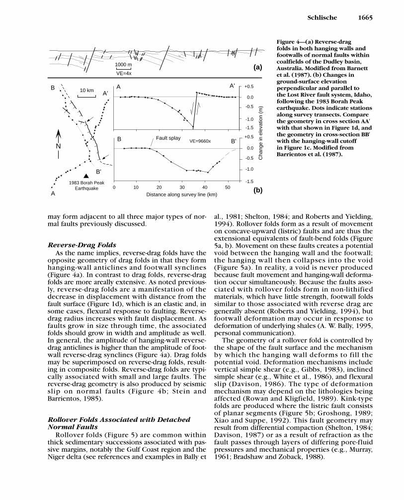
opposite geometry of drag folds in that they formhanging-wall anticlines and footwall synclines(Figure 4a). In contrast to drag folds, reverse-dragfolds are more areally extensive. As noted previous-ly, reverse-drag folds are a manifestation of thedecrease in displacement with distance from thefault surface (Figure 1d), which is an elastic and, insome cases, flexural response to faulting. Reverse-drag radius increases with fault displacement. Asfaults grow in size through time, the associatedfolds should grow in width and amplitude as well.In general, the amplitude of hanging-wall reverse-drag anticlines is higher than the amplitude of foot-wall reverse-drag synclines (Figure 4a). Drag foldsmay be superimposed on reverse-drag folds, result-ing in composite folds. Reverse-drag folds are typi-cally associated with small and large faults. Thereverse-drag geometry is also produced by seismicslip on normal faults (Figure 4b; Stein andBarrientos, 1985).
Rollover Folds Associated with DetachedNormal Faults
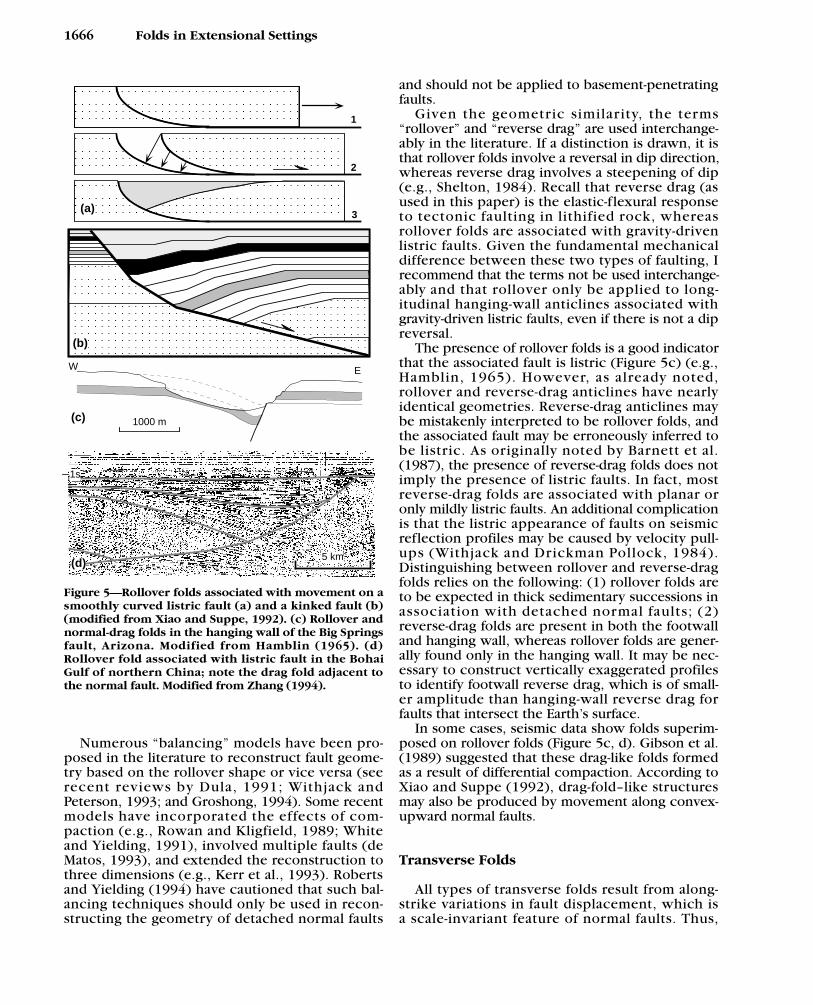
Rollover folds (Figure 5) are common withinthick sedimentary successions associated with pas-sive margins, notably the Gulf Coast region and theNiger delta (see references and examples in Bally et
al., 1981; Shelton, 1984; and Roberts and Yielding,1994). Rollover folds form as a result of movementon concave-upward (listric) faults and are thus theextensional equivalents of fault-bend folds (Figure5a, b). Movement on these faults creates a potentialvoid between the hanging wall and the footwall;the hanging wall then collapses into the void(Figure 5a). In reality, a void is never producedbecause fault movement and hanging-wall deforma-tion occur simultaneously. Because the faults asso-ciated with rollover folds form in non-lithifiedmaterials, which have little strength, footwall foldssimilar to those associated with reverse drag aregenerally absent (Roberts and Yielding, 1994), butfootwall deformation may occur in response todeformation of underlying shales (A. W. Bally, 1995,personal communication).
The geometry of a rollover fold is controlled bythe shape of the fault surface and the mechanismby which the hanging wall deforms to fill thepotential void. Deformation mechanisms includevertical simple shear (e.g., Gibbs, 1983), inclinedsimple shear (e.g., White et al., 1986), and flexuralslip (Davison, 1986). The type of deformationmechanism may depend on the lithologies beingaffected (Rowan and Kligfield, 1989). Kink-typefolds are produced where the listric fault consistsof planar segments (Figure 5b; Groshong, 1989;Xiao and Suppe, 1992). This fault geometry mayresult from differential compaction (Shelton, 1984;Davison, 1987) or as a result of refraction as thefault passes through layers of differing pore-fluidpressures and mechanical properties (e.g., Murray,1961; Bradshaw and Zoback, 1988).
Schlische 1665
Cha
nge
in e
leva
tion
(m)
1000 m
VE=4x(a)
0 10 20 30 40 50
Distance along survey line (km)
10 km0.0
-1.0
+0.5
-0.5
-1.5
0.0
-1.0
+0.5
-0.5
-1.5
A'
B
B'
A
Fault splay
B AA'
B'
1983 Borah PeakEarthquake
NVE=9660x
(b)
Figure 4—(a) Reverse-drag folds in both hanging walls andfootwalls of normal faults withincoalfields of the Dudley basin,Australia. Modified from Barnettet al. (1987). (b) Changes inground-surface elevation perpendicular and parallel to the Lost River fault system, Idaho,following the 1983 Borah Peakearthquake. Dots indicate stationsalong survey transects. Comparethe geometry in cross section AA′with that shown in Figure 1d, andthe geometry in cross-section BB′with the hanging-wall cutoff in Figure 1c. Modified from Barrientos et al. (1987).
Numerous “balancing” models have been pro-posed in the literature to reconstruct fault geome-try based on the rollover shape or vice versa (seerecent reviews by Dula, 1991; Withjack andPeterson, 1993; and Groshong, 1994). Some recentmodels have incorporated the effects of com-paction (e.g., Rowan and Kligfield, 1989; Whiteand Yielding, 1991), involved multiple faults (deMatos, 1993), and extended the reconstruction tothree dimensions (e.g., Kerr et al., 1993). Robertsand Yielding (1994) have cautioned that such bal-ancing techniques should only be used in recon-structing the geometry of detached normal faults
and should not be applied to basement-penetratingfaults.
Given the geometric similar ity, the terms“rollover” and “reverse drag” are used interchange-ably in the literature. If a distinction is drawn, it isthat rollover folds involve a reversal in dip direction,whereas reverse drag involves a steepening of dip(e.g., Shelton, 1984). Recall that reverse drag (asused in this paper) is the elastic-flexural responseto tectonic faulting in lithified rock, whereasrollover folds are associated with gravity-drivenlistric faults. Given the fundamental mechanicaldifference between these two types of faulting, Irecommend that the terms not be used interchange-ably and that rollover only be applied to long-itudinal hanging-wall anticlines associated withgravity-driven listric faults, even if there is not a dipreversal.
The presence of rollover folds is a good indicatorthat the associated fault is listric (Figure 5c) (e.g.,Hamblin, 1965). However, as already noted,rollover and reverse-drag anticlines have nearlyidentical geometries. Reverse-drag anticlines maybe mistakenly interpreted to be rollover folds, andthe associated fault may be erroneously inferred tobe listric. As originally noted by Barnett et al.(1987), the presence of reverse-drag folds does notimply the presence of listric faults. In fact, mostreverse-drag folds are associated with planar oronly mildly listric faults. An additional complicationis that the listric appearance of faults on seismicreflection profiles may be caused by velocity pull-ups (Withjack and Drickman Pollock, 1984).Distinguishing between rollover and reverse-dragfolds relies on the following: (1) rollover folds areto be expected in thick sedimentary successions inassociation with detached normal faults; (2)reverse-drag folds are present in both the footwalland hanging wall, whereas rollover folds are gener-ally found only in the hanging wall. It may be nec-essary to construct vertically exaggerated profilesto identify footwall reverse drag, which is of small-er amplitude than hanging-wall reverse drag forfaults that intersect the Earth’s surface.
In some cases, seismic data show folds superim-posed on rollover folds (Figure 5c, d). Gibson et al.(1989) suggested that these drag-like folds formedas a result of differential compaction. According toXiao and Suppe (1992), drag-fold–like structuresmay also be produced by movement along convex-upward normal faults.
Transverse Folds
All types of transverse folds result from along-strike variations in fault displacement, which isa scale-invariant feature of normal faults. Thus,
1666 Folds in Extensional Settings
(b)
(a)
1
2
3
5 km
E
1000 m(c)
W
1s
(d)
Figure 5—Rollover folds associated with movement on asmoothly curved listric fault (a) and a kinked fault (b)(modified from Xiao and Suppe, 1992). (c) Rollover andnormal-drag folds in the hanging wall of the Big Springsfault, Arizona. Modified from Hamblin (1965). (d)Rollover fold associated with listric fault in the BohaiGulf of northern China; note the drag fold adjacent tothe normal fault. Modified from Zhang (1994).
transverse folds also exist on a variety of scales. Thestyle of transverse folding depends largely on thegeometry of the normal fault system (isolated faultvs. segmented fault system).
Folds Associated with an Isolated FaultIn the hanging wall of a single isolated fault,
along-strike variations in fault displacement pro-duce a broad, elongated syncline that plungestoward the fault (Figure 2b); for a large isolatedbasin-bounding fault, the syncline defines a sedi-mentary basin (Figure 6a). A broad, elongated anti-cline, plunging away from the fault, is present inthe footwall (Figures 2b, 6a). The fold hinges forboth folds should be collinear and are located inthe region of maximum fault displacement (Figures2b, 6a). The amplitude of the syncline is commonlygreater than the amplitude of the anticline, as hang-ing-wall displacement is commonly greater thanfootwall displacement. As a result of fault and basingrowth, the amplitude of the folds and the width ofthe folds increase through time, although the hingelines are likely to remain relatively fixed (Figure6a). Hinge-line migration may occur if the area ofmaximum displacement shifts position throughtime, which might be recognizable by the presenceof curved axial surfaces (Schlische and Anders, inpress).
Folds Associated with Segmented FaultSystems
Segmented fault systems are commonly associat-ed with multiple displacement minima and maxima(Figure 6b–e). For the hanging wall of the fault sys-tem, synclines form at local displacement maxima,typically located at or near the centers of the faultsegments; anticlines form at local displacementminima, typically located near fault segmentboundaries (Figure 7a). The synclines are consider-ably wider than the anticlines, which are common-ly associated with relay ramps between overlap-ping fault segments. The concept of relay rampsand displacement transfer between overlappingfaults can largely be traced to Larsen’s (1988) studyof the geometry of segmented normal fault systemsin Permian rifts of Greenland (Figure 7b), wheremultiple transverse folds are found in the hangingwall (Figure 7c).
In the footwall of a segmented fault system, anti-clines form at local displacement maxima, which,when present, are typically located at or near thecenters of fault segments; synclines form at localdisplacement minima, which, when present, aretypically located at fault segment boundaries. Theextent to which transverse folds are developed inthe footwall and the hanging wall depends on the
number of active fault segments, the stage in theevolution of the fault system, and the nature of thefault segment geometry. According to Anders andSchlische (1994) and Schlische and Anders (inpress), fault geometry for multiple-segment faultsystems can be classified as (1) nonoverlapping,(2) closely overlapping, and (3) widely overlap-ping. For each broad class, additional geometriesare possible depending on whether the faults dipsynthetically or antithetically. The evolutionarymodels for the specific cases shown in Figure 6,which are based on Schlische and Anders (inpress), apply to basin-scale fault systems. However,as noted previously, the displacement geometriesare scale invariant.
In the case of nonoverlapping synthetic faults,isolated synclinal subbasins originally form in thehanging wall (Figure 6b, stage 1). Footwall upliftprofiles define broad anticlines associated with theisolated fault segments. As displacement accrues,the fault tips propagate laterally, and the fault seg-ments eventually link together. At this stage, thesynclinal subbasins are separated by a transversehigh located in the region of low displacementwhere the faults linked together (Figure 6b, stage2); the opposite fold geometry exists in the foot-wall. Eventually, displacement must increase in thezone of linkage so that the maximum displacementon the fault system conforms to length-displace-ment scaling relationships (Anders and Schlische,1994). Thus, the transverse high gradually subsides,eventually resulting in a single elongated synclinein the hanging wall and a single elongated anticlinein the footwall (Figure 6b, stage 3).
The initial geometry of the structures associatedwith closely overlapping synthetic faults is similarto that of nonoverlapping synthetic faults (Figure6c, stage 1). As the fault tips propagate laterally andbegin to overlap, a transverse anticline forms andseparates two synclines in the hanging wall (Figure6c, stage 2); a transverse syncline forms in the foot-wall in the area of overlap. According to Andersand Schlische (1994), the transverse anticline inthe hanging wall will persist as long as multiplefault segments are coevally active so that slip is dis-tributed on multiple faults, thus reducing theamount of hanging-wall subsidence (Figure 6c,stage 3). If the overlapping faults physically linktogether, then the transverse high will eventuallysubside. Anders and Schlische (1994) suggestedthat the footwall elevation low will gradually disap-pear, even if multiple overlapping fault segmentsremain active (Figure 6c, stage 3). This is becausethe footwall elevation profile reflects the total dis-placement on the fault system (particularly thedisplacement at depth), whereas the near-surface dis-placement on the nearest fault segment determinesthe depth of the hanging-wall basin.
Schlische 1667

1668 Folds in Extensional Settings
(a) (b)
(c)
(d)
(e)
1
2
3
1
2
3
1
2
3
1
2
3
1
2
3
1 23
1 23
1 231
23
123
Figure 6—Evolution of extensional basins resulting from fault growth. Each panel shows three stages in the hang-ing-wall evolution of an extensional basin or subbasin system; ball-and-bar symbols indicate normal faults. Longitu-dinal sections shown for each stage in basin evolution [except stages 1 and 2 for (d) and (e)]. The lower diagram ineach panel shows geometry of footwall uplift after each of the three stages. (a) Single fault; (b) nonoverlapping syn-thetic fault segments; (c) closely spaced overlapping synthetic fault segments; (d) widely spaced overlapping syn-thetic fault segments; and (e) antithetic fault segments. Simplified from Schlische and Anders (in press).

In the case of widely spaced overlapping syn-thetic faults, originally isolated synclinal subbasinsnever merge during fault-tip propagation (Figure6d). Each fault segment is associated with its ownanticlinal footwall uplift geometry. However, thesummed footwall uplift profile resembles that of asingle continuous fault.
The relay geometry of synthetic overlappingfaults may not persist indefinitely (Peacock andSanderson, 1991; Childs et al., 1995). Relay zonesare commonly breached by faults that connect themain fault segments. This may account for the dog-leg or zig-zag geometry of some normal fault sys-tems (e.g., Harding, 1984).
An example of the evolution of one type of anti-thetic fault system is shown in Figure 6e. Each faultsegment produces an originally isolated synclinalsubbasin. As the tips propagate, the faults curvetoward one another to prevent interference.Reduced displacement at the fault tips coupled withgreater strike slip on fault segments oblique to theextension direction result in reduced subsidence in
the area of fault overlap, forming a transverse anti-cline. If the faults did not curve in this manner, atransfer fault would need to form between them.The footwall fold pattern consists of isolated anti-clines; this geometry persists through time.Additional examples of the geometry of antitheticfault systems are provided by Morley et al. (1990).
Examples of Basin-Scale Transverse FoldsThe Beaverhead and Lost River fault systems of
Idaho (northern Basin and Range) each consist of sixfault segments (Anders and Schlische, 1994; Figure8a). Segment boundaries marked by closely overlap-ping faults (shaded) are associated with hanging-wallhighs (intrabasin highs) manifested as Bougueranomaly highs (indicating shallower depth to base-ment). In the regions of overlap, there is no associat-ed footwall elevation low. Rather, the anticlinal foot-wall uplift profiles resemble those of a single fault,suggesting that all of the fault segments are kinemati-cally linked. The geometries depicted in Figure 8a
Schlische 1669
Rider block
Relay r
amp
Relay r
amp
Footwall uplift
800
400
2000
0
-200
0
400
0
-100
0
-800
-200
-600
5 km
DU
D
DU
DU
UD D U
DU
DU
Relay ramp
Relayramp
0
1000
-1000A
A'
A A'
(a) (b)
(c)
Figure 7—(a) Geometric relationships among a segmented normal fault system, relay ramps, transverse folds, andrider blocks. Simplified from Schlische (1993). (b) Structure-contour map of the top of basement (datum is mean sealevel) within a Permian rift basin, Greenland. Note relay ramps between offset fault segments, basement highs (trans-verse anticlines) at fault segment boundaries, and basement lows (transverse synclines) near the centers of fault seg-ments. Adapted from Larsen (1988). (c) Longitudinal profile of top of basement along section AA′ shown in (b).
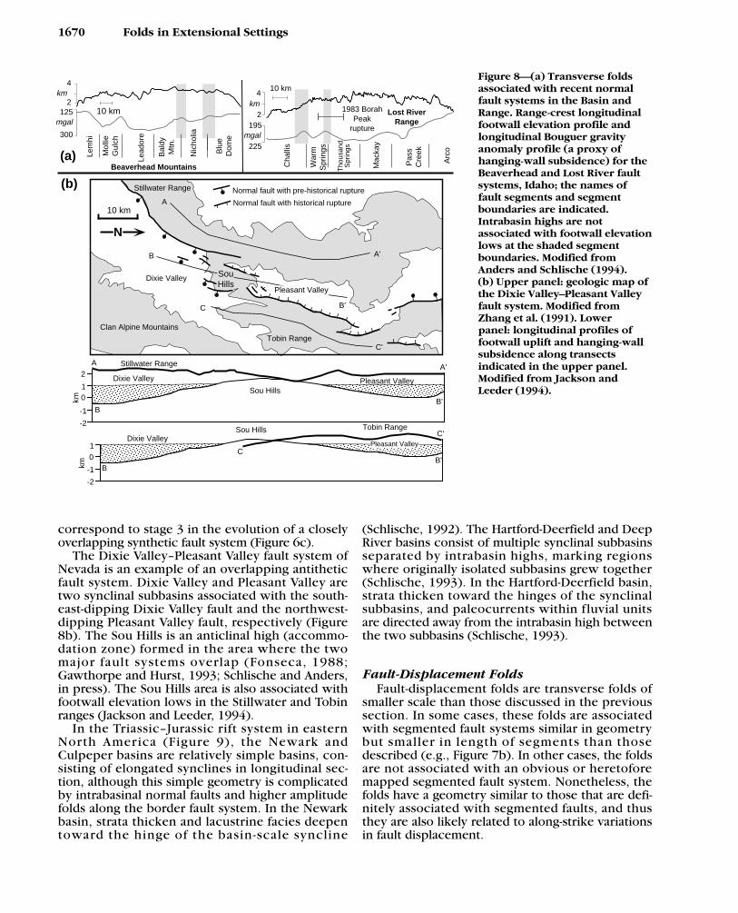
correspond to stage 3 in the evolution of a closelyoverlapping synthetic fault system (Figure 6c).
The Dixie Valley–Pleasant Valley fault system ofNevada is an example of an overlapping antitheticfault system. Dixie Valley and Pleasant Valley aretwo synclinal subbasins associated with the south-east-dipping Dixie Valley fault and the northwest-dipping Pleasant Valley fault, respectively (Figure8b). The Sou Hills is an anticlinal high (accommo-dation zone) formed in the area where the twomajor fault systems overlap (Fonseca, 1988;Gawthorpe and Hurst, 1993; Schlische and Anders,in press). The Sou Hills area is also associated withfootwall elevation lows in the Stillwater and Tobinranges (Jackson and Leeder, 1994).
In the Triassic–Jurassic rift system in easternNorth America (Figure 9), the Newark andCulpeper basins are relatively simple basins, con-sisting of elongated synclines in longitudinal sec-tion, although this simple geometry is complicatedby intrabasinal normal faults and higher amplitudefolds along the border fault system. In the Newarkbasin, strata thicken and lacustrine facies deepentoward the hinge of the basin-scale syncline
(Schlische, 1992). The Hartford-Deerfield and DeepRiver basins consist of multiple synclinal subbasinsseparated by intrabasin highs, marking regionswhere originally isolated subbasins grew together(Schlische, 1993). In the Hartford-Deerfield basin,strata thicken toward the hinges of the synclinalsubbasins, and paleocurrents within fluvial unitsare directed away from the intrabasin high betweenthe two subbasins (Schlische, 1993).
Fault-Displacement FoldsFault-displacement folds are transverse folds of
smaller scale than those discussed in the previoussection. In some cases, these folds are associatedwith segmented fault systems similar in geometrybut smaller in length of segments than thosedescribed (e.g., Figure 7b). In other cases, the foldsare not associated with an obvious or heretoforemapped segmented fault system. Nonetheless, thefolds have a geometry similar to those that are defi-nitely associated with segmented faults, and thusthey are also likely related to along-strike variationsin fault displacement.
1670 Folds in Extensional Settings
Lost RiverRange
10 km
1983 BorahPeak
rupture
4
2195
225
km
mgal
Cha
llis
War
mS
prin
gs
Tho
usan
dS
prin
gs
Mac
kay
Pas
sC
reek
Arc
o
Beaverhead Mountains
10 km
4
2km
125
300
mgal
Lem
hi
Mol
lieG
ulch
Lead
ore
Bal
dyM
tn.
Nic
holia
Blu
eD
ome
2
10
-2
-1
Dixie Valley
Stillwater Range
Sou HillsPleasant Valley
A A'
BB'km
10
-1
-2
Pleasant Valley
Tobin RangeSou HillsDixie Valley
BB'
C
C'
km
SouHills
Pleasant Valley
Tobin Range
Dixie Valley
Stillwater Range
Clan Alpine Mountains
A
A'B
B'C
C'
N
10 km
Normal fault with pre-historical rupture
Normal fault with historical rupture
(b)
(a)
Figure 8—(a) Transverse foldsassociated with recent normalfault systems in the Basin andRange. Range-crest longitudinalfootwall elevation profile andlongitudinal Bouguer gravityanomaly profile (a proxy ofhanging-wall subsidence) for theBeaverhead and Lost River faultsystems, Idaho; the names offault segments and segmentboundaries are indicated. Intrabasin highs are not associated with footwall elevationlows at the shaded segmentboundaries. Modified fromAnders and Schlische (1994). (b) Upper panel: geologic map ofthe Dixie Valley–Pleasant Valleyfault system. Modified fromZhang et al. (1991). Lower panel: longitudinal profiles offootwall uplift and hanging-wallsubsidence along transects indicated in the upper panel.Modified from Jackson and Leeder (1994).

Transverse folds are present along the borderfault system in the northeastern part of the Newarkbasin (Figure 9b). These folds decrease in amplitudeaway from the fault, clearly do not affect the entire
width of the basin, and are not associated with anyobvious or mapped fault segmentation. In the south-western part of the basin, transverse folds are alsowell developed (cross section BB′ in Figure 9c), but
Schlische 1671
TA TA
TA
Bend in profileF F'
VE: x2
C C'U
E'
E
Culpeper basin
Deep Riverbasin
U
U
400 km
DRN
C
N
HD
F'
D=DeerfieldH=HartfordN=NewarkC=CulpeperDR=Deep River
E E'U
A'
A
Hartfordsubbasin
Newarkbasin
C
C'Interbedded lava flowsand lacustrine strata
Diabase intrusions
Mostly deep-waterlacustrine strata
Mostly fluvial strata
Mostly shallow-waterlacustrine strata
Border fault
Other fault
Undifferentiated strataU
A A'U
N25 km
F
B
B'
Fig. 10
Fig. 11
B B'
D'
D
D D'
U
U
Fig. 14
h
f
(b)
(c)
(a)
Deerfieldsubbasin
U
Coastal Plain cover
Figure 9—Simplified geologic maps (b) and schematic longitudinal cross sections (c) of selected Mesozoic rift basinsof eastern North America (a). f = Flemington fault; h = Hopewell fault; A = motion away from reader; T = motiontoward reader. Modified from Schlische (1992, 1993).
..

in this case there is a clear association between thefolds and a highly segmented border fault system(Figure 10a). The local and regional geometry of thefolds is most compatible with normal faulting (seeSchlische, 1992, for further discussion).
Outcrop and seismic reflection data from theJacksonwald-Sassamansville area in the southwest-ern Newark basin constrain the timing of deforma-tion. In the Jacksonwald syncline, stratigraphicmarker beds are thicker in the hinge than alongthe limbs (Figure 10a) (Schlische, 1992). Reynolds(1994) analyzed a grid of seismic reflection pro-files (provided by North-Central Oil and ExxonCorporation) in the southwestern Newark basin.Line NC 2-1 is oriented subparallel to the borderfault system (Figure 10b). Reynolds’ interpretationshows that synrift strata and the top of basementare concordantly folded. Although the border faultsystem is not planar, its irregularities do not sys-tematically correlate with the overlying folds. As
constrained by the seismic data and the Parestiswell, the Lockatong Formation is thinnest alongthe crest of the Sassamansville anticline and thick-ens into the flanking synclines (Figure 10b). Bothstudies clearly indicate syndepositional folding.
Transverse folds are also well developed along theFlemington and Hopewell intrabasinal normal faultsystems (f and h in Figure 9b). The amplitude of fold-ing decreases with distance from the Flemingtonfault system in the hanging wall (Figure 11a). Nofolds of a scale similar to those in the hanging wallare present in the footwall. Stratigraphic data frommarker beds that have been traced across the folds(Olsen et al., in press) indicate that units thicken andlacustrine facies deepen away from the anticlinalhinge (Figure 11b), strongly suggesting syndeposi-tional folding. A drag fold is present near the south-western end of the fault shown in Figure 11a.
As displacement increases on faults or fault seg-ments, transverse folds must increase in amplitude.
1672 Folds in Extensional Settings
25
5026 43
35
12
15
20
30
30
18
12
12
5 km
5.1
7.6
N
Sassamansvillesyncline anticline
Jacksonwaldsyncline
9.2
1 km
Passaic FormationDiabase
Basement
2-3Parestis
Well
Sassamansville anticline
NNESSW
1
0
2
2-4
Border fault system
Lockatong Fm.
Sassamansville syncline
(b)
Tw
o-w
ay T
rave
ltim
e (s
)
(a)
NC 2-1
Stockton Fm.
Lockatong Fm.
Passaic Fm.
Jacksonwald Basalt
Diabase
Conglomerate Strike/dip of bedding30SynclineAnticline
Seismic lineNormal fault
Form line of bedding
Drill holeStrike-slip fault(dashed where inferred)
Figure 10—(a) Geologicmap of the southwesternNewark basin (see Figure 9bfor location) showing transverse folds associatedwith a segmented fault system and location of seismic lines studied byReynolds (1994). Circlednumbers indicate thicknesses of marker unit in meters. Modifiedfrom Schlische (1992). (b) Geologic interpretationof longitudinal seismic lineNC 2-1. Modified fromReynolds (1994).

Consequently, bed lengths of units deformed by thefolding must increase through time (Figure 12a).Transverse folding of this type therefore leads to theformation of fold-parallel (fault-perpendicular) exten-sional structures, such as joints, normal faults, anddikes. Such relatively small-scale accommodationstructures have been imaged on a seismic reflectionprofile of a transverse fold in the North Sea (Figure12b, c) (Roberts et al., 1990). The normal faults forma conjugate system, dipping toward the locus of
greatest subsidence, and are restricted to older hori-zons that have been downwarped the most. Stratathicken toward the center of this syndepositionalstructure. [It should be noted that Roberts et al.(1990) ascribed this fold to strike slip, but its geome-try is very similar to other transverse folds describedin this report, and is probably a fault-displacement
Schlische 1673
5 kmN
3
2
1
L
S
P
OF
O
P
10 m
Somersetcore
Flemington(1)
Copper Hill (2)
Muirheld(3)
Ukr
aini
anM
embe
rC
edar
Gro
ve M
b.
Black laminated mudstoneGray thin-bedded mudstonePurple mudstoneRed massive mudstone
(a)
(b)
Figure 11—(a) Geologic map of a part of the Flemingtonintrabasinal fault system of the central Newark basin (seeFigure 9b for location), with transverse folds in the hang-ing wall. F = Feltville Formation; L = Lockatong Forma-tion; O = Orange Mountain Basalt; P = Passaic Formation;S = Stockton Formation. Thin black lines are marker bedsconsisting of deeper water lacustrine strata. (b) Measuredstratigraphic sections [see (a) for locations] and paleo-magnetic polarity stratigraphy (black is normal, white isreversed) of top of the Cedar Grove Member and base ofthe Ukrainian Member, showing thinning toward theanticlinal hinge and thickening toward the synclinalhinges. Modified from Olsen et al. (in press).
Line x
(a)
2 km
Transverse syncline
1 s
3 s
WSW ESE
2200
2000
1800
1000
12001400
1600
12001400
1000
1200
1400
1600
2000
2200
1800 200022
00 24002600
1600
1400
1200
1800
58°30'N
2°45'W 2°30'W
5 km
U
D
D
U
U
D
U D DU
DU
D
UD
U
D
U
D
U
DU
DU
N
Structure contour mapTWT, milliseconds
Top Zechstein
Top Triassic
Seismic line
(b)
(c)
bK
tTr
tZtD
1000 m
VE=2x Bend in sectionA A'
6000
6500
N
AA'
(d)
6500
Figure 12—(a) Changes in bed length during fault-dis-placement folding accommodated by transverse normalfaulting. (b) Structure contour map of a part of theNorth Sea, with faulted transverse syncline imaged onseismic reflection profile (c). tD = top Devonian; tZ = topZechstein; tTr = top Triassic; bK = base Cretaceous. Mapsimplified from and original seismic data presented byRoberts et al. (1990). (d) Footwall anticline associatedwith normal fault system (ball-and-bar symbols) in theBeatrice field, North Sea. Contours are depth in feet tothe upper surface of the reservoir unit. Modified fromLinsley et al. (1980).

fold (A. M. Roberts, 1995, personal communica-tion).] In the southwestern Newark basin (Figure10a), a large northwest-striking subvertical dike sub-parallels the hinge of the Jacksonwald syncline, andis likely a fold-parallel extensional structure thataccommodated progressive transverse folding.
A hierarchy of fault-displacement folds is presentin the Newark basin and presumably other basins aswell. The largest scale fold is associated with thebasin itself (Figures 9b and 13); this suggests that onthe largest scale, the basin appears to be bounded bya single continuous border fault, although the borderfault is mapped as consisting of numerous fault seg-ments. Superimposed on the basin-scale fold aretransverse folds associated with the segmented bor-der fault (Figure 13). Their effects are relatively local-ized; the hinged margin is clearly not affected bythese folds (Figure 13). The distance of the hingedmargin from the border fault system (i.e., the widthof the basin) is a proxy of the total amount of exten-sion experienced on the border fault system and theintrabasinal faults, both mapped and hidden. Asnoted by Marrett and Allmendinger (1992) andWalsh et al. (1991), hidden (i.e., small) faults com-monly account for significant amounts of extension.Although each fault segment has a local displace-ment minimum at a fault segment boundary, result-ing in the formation of an anticline in the immediatevicinity of the segment boundary, the sum of the dis-placements on the overlapping faults and any otherfaults balances for the localized deficits on any indi-vidual fault (Figure 13). To produce the overall syn-clinal geometry of the Newark basin, the centralfault segments must have greater displacement thanthe distal segments. In addition, intrabasinal faultsare concentrated in the central part of the Newarkbasin (Figure 9b) and may contribute to the greaterwidth of the basin in that area.
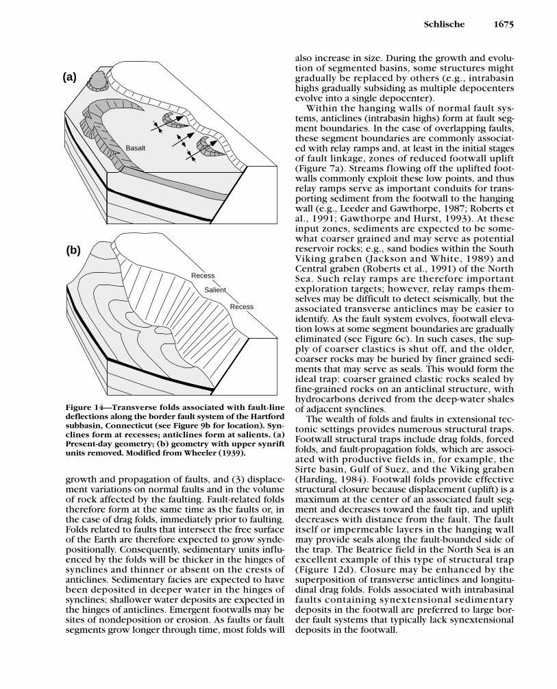
Fault-Line Deflection FoldsFault-line deflection folds were first described by
Wheeler (1939). These transverse folds are associated
with nonplanar fault surfaces. Synclines form atrecesses (convex toward the footwall) in the fault sur-face, whereas anticlines form at salients (convextoward the hanging wall) (Figure 14). The amplitudeof folding decreases away from the fault-line deflec-tion, which is attributable to an “evening-out” effectwith distance from the fault. The fault-segmentationmodel for the formation of transverse folds and thefault-line deflection model are not necessarily mutual-ly exclusive because many segment boundaries (areasof displacement deficits) are marked by salients in thefault surface (e.g., Machette et al., 1991) and thustransverse anticlines. Dog-leg or zig-zag-type fault sys-tems resulting from breached relay zones of overlap-ping faults may also be associated with fault-linedeflection folds.
Fault-line deflections (undulations) have also beenreported from several detachment faults in thesouthwestern United States (e.g., Davis and Lister,1988). These folds have wavelengths of several tensof meters to hundreds of meters; the axes of thesefolds are subparallel to the slip direction. Meter-scalestructures on neotectonic normal faults are referredto as corrugations by Stewart and Hancock (1991).
Interference Folds
The folds described previously account for thevast majority of folds found in extensional settings,but there are some additional examples that are noteasily classified as transverse or longitudinal.Interference folds form when one type of fold issuperimposed on another; for example, longitudinalfolds superimposed on transverse folds. Dependingon the geometry of the superimposed folds, domes,basins, saddles, and culminations (Figure 12d) maybe produced.
DISCUSSION
The majority of the folds described previouslyare related to (1) movement on normal faults, (2)
1674 Folds in Extensional Settings
Min
imum
segm
ent
and
BF
Sdi
spla
cem
ent
Min
imum
segm
ent
and
BF
Sdi
spla
cem
ent
Maximum fault segmentdisplacement
Maximum BFSand faultsegment
displacement
Localminimum
Maximumfault segmentdisplacement
Localminimum
Hinged marginunaffected byBFS segmentation
Hinged marginaffected by
BFS segmentation(not observed)
"Folded"marker bed
Figure 13—Hierarchy of transversefolds associated with extensionalbasins. BFS refers to border faultsystem. Ball-and-bar symbolsdenote normal faults. See text fordiscussion.
growth and propagation of faults, and (3) displace-ment variations on normal faults and in the volumeof rock affected by the faulting. Fault-related foldstherefore form at the same time as the faults or, inthe case of drag folds, immediately prior to faulting.Folds related to faults that intersect the free surfaceof the Earth are therefore expected to grow synde-positionally. Consequently, sedimentary units influ-enced by the folds will be thicker in the hinges ofsynclines and thinner or absent on the crests ofanticlines. Sedimentary facies are expected to havebeen deposited in deeper water in the hinges ofsynclines; shallower water deposits are expected inthe hinges of anticlines. Emergent footwalls may besites of nondeposition or erosion. As faults or faultsegments grow longer through time, most folds will
also increase in size. During the growth and evolu-tion of segmented basins, some structures mightgradually be replaced by others (e.g., intrabasinhighs gradually subsiding as multiple depocentersevolve into a single depocenter).
Within the hanging walls of normal fault sys-tems, anticlines (intrabasin highs) form at fault seg-ment boundaries. In the case of overlapping faults,these segment boundaries are commonly associat-ed with relay ramps and, at least in the initial stagesof fault linkage, zones of reduced footwall uplift(Figure 7a). Streams flowing off the uplifted foot-walls commonly exploit these low points, and thusrelay ramps serve as important conduits for trans-porting sediment from the footwall to the hangingwall (e.g., Leeder and Gawthorpe, 1987; Roberts etal., 1991; Gawthorpe and Hurst, 1993). At theseinput zones, sediments are expected to be some-what coarser grained and may serve as potentialreservoir rocks; e.g., sand bodies within the SouthViking graben (Jackson and White, 1989) andCentral graben (Roberts et al., 1991) of the NorthSea. Such relay ramps are therefore importantexploration targets; however, relay ramps them-selves may be difficult to detect seismically, but theassociated transverse anticlines may be easier toidentify. As the fault system evolves, footwall eleva-tion lows at some segment boundaries are graduallyeliminated (see Figure 6c). In such cases, the sup-ply of coarser clastics is shut off, and the older,coarser rocks may be buried by finer grained sedi-ments that may serve as seals. This would form theideal trap: coarser grained clastic rocks sealed byfine-grained rocks on an anticlinal structure, withhydrocarbons derived from the deep-water shalesof adjacent synclines.
The wealth of folds and faults in extensional tec-tonic settings provides numerous structural traps.Footwall structural traps include drag folds, forcedfolds, and fault-propagation folds, which are associ-ated with productive fields in, for example, theSirte basin, Gulf of Suez, and the Viking graben(Harding, 1984). Footwall folds provide effectivestructural closure because displacement (uplift) is amaximum at the center of an associated fault seg-ment and decreases toward the fault tip, and upliftdecreases with distance from the fault. The faultitself or impermeable layers in the hanging wallmay provide seals along the fault-bounded side ofthe trap. The Beatrice field in the North Sea is anexcellent example of this type of structural trap(Figure 12d). Closure may be enhanced by thesuperposition of transverse anticlines and longitu-dinal drag folds. Folds associated with intrabasinalfaults containing synextensional sedimentarydeposits in the footwall are preferred to large bor-der fault systems that typically lack synextensionaldeposits in the footwall.
Schlische 1675
Recess
Salient
Recess
(b)
(a)
Basalt
Figure 14—Transverse folds associated with fault-linedeflections along the border fault system of the Hartfordsubbasin, Connecticut (see Figure 9b for location). Syn-clines form at recesses; anticlines form at salients. (a)Present-day geometry; (b) geometry with upper synriftunits removed. Modified from Wheeler (1939).
Structural traps in the hanging walls of normalfaults include the aforementioned fault-displace-ment anticlines associated with segmented faultsystems and relay ramps and rollover folds (e.g.,Shelton, 1984). Hanging-wall reverse-drag anti-clines affecting units with regional subhorizontalorientation may not provide closure, especially ifsuperposed transverse synclines create saddlestructures. Closure may be possible if the regionaldip is in the same direction as the dip direction ofthe fault. Interference folds, particularly domes andculminations, also may form structural traps.
In regions in which strata lack primary porosityand permeability, secondary fracture porosity isextremely important. Secondary structures associ-ated with folds that may contribute to fracture per-meability include (1) fold-parallel extensional struc-tures that accommodate downwarping andupwarping associated with fault-displacement folds(Figure 12a), (2) fold-parallel faults and shear zonesthat accommodate reverse-drag and rollover fold-ing, and (3) extensional structures in the lowerfootwall and upper hanging-wall quadrants associ-ated with displacement fields on blind faults(Figure 1d).
Longitudinal folds, such as drag folds androllover folds, have long been recognized as beingassociated with normal faults. One of the goals ofthis paper is to show that transverse folds are equal-ly as common as longitudinal folds. Hopefully, theidealized models and examples of fault-associatedfolds presented in this paper will allow for aug-mented interpretations of seismic reflection pro-files in areas of poor data quality.
SUMMARY AND CONCLUSIONS
(1) Characteristics of normal faults that influ-ence associated folds include the following: maxi-mum displacement occurs at the center of the faultand decreases toward the fault tips; displacementdecreases with distance from the fault surface;faults increase in length as displacement increases;and fault systems are commonly segmented.
(2) Folds associated with normal faults canbroadly be classified as fault-parallel (longitudinalfolds) and fault-normal (transverse folds).
(3) Drag folds (including forced folds and fault-propagation folds) are longitudinal folds that formlargely as a result of the growth of faults intoregions of monoclinal folding at the tips of faults;synclines are present in the hanging wall; anticlinesare present in the footwall. Such folds may also beproduced by frictional drag and differential com-paction.
(4) As defined in this paper, reverse-drag foldsare longitudinal folds that are a manifestation of the
elastic (and in some cases f lexural) response tofaulting that results in a decrease in displacementwith distance from the fault; these folds consist ofhanging-wall anticlines and footwall synclines.
(5) As defined in this paper, rollover folds arelongitudinal folds that form as a result of movementon nonplanar (typically listric) faults in unlithifiedsediments in which movement is driven by gravitysliding. Anticlines form in the hanging wall; thefootwall is generally unfolded. Although rolloveranticlines are geometrically similar to reverse-draganticlines, the causal mechanism is different. Thisgeometry by itself cannot be used to infer the exis-tence of listric faults. Balancing techniques used toinfer fault geometry can only be used for rolloverfolds associated with gravity-driven faults.
(6) The majority of transverse folds form as aresult of along-strike variations in fault displacement.In the hanging wall, synclines form near displace-ment maxima, typically at or near the centers of faultsegments. Anticlines form near displacement mini-ma, typically near fault segment boundaries.Synclines tend to be broader than anticlines. In thefootwall, anticlines form at displacement maxima,and synclines form at displacement minima. Thegeometry of transverse folds is strongly influencedby the growth and linkage of fault segments.
(7) Fault-line deflection folds are transverse foldsrelated to undulations on the fault surfaces, withsynclines forming at recesses and anticlines form-ing at salients.
(8) Interference folds result from the superposi-tion of longitudinal and transverse folds, andinclude domes, basins, culminations, and saddles.
(9) All of the folds described form at the sametime as or just prior to faulting. For faults that inter-sect the Earth’s surface, the associated folds devel-op syndepositionally. Synfolding sedimentarydeposits are thicker in the hinges of synclines andthinner in the hinges of anticlines; water-depth–dependent facies are deeper in synclines than anti-clines. Coarser grained facies tend to accumulate atanticlines (intrabasin highs) associated with faultsegment boundaries and relay ramps.
REFERENCES CITEDAnders, M. H., and R. W. Schlische, 1994, Overlapping faults, intra-
basin highs, and the growth of normal faults: Journal ofGeology, v. 102, p. 165–180.
Bally, A. W., D. Bernoulli, G. A. Davis, and L. Montadert, 1981,Listric normal faults: Oceanological Acta, 26th InternationalGeological Congress, Paris, p. 87–101.
Barnett, J. A. M., J. Mortimer, J. H. Rippon, J. J. Walsh, and J.Watterson, 1987, Displacement geometry in the volume con-taining a single normal fault: AAPG Bulletin, v. 71, p. 925–937.
Barrientos, S. E., R. S. Stein, and S. N. Ward, 1987, Comparison ofthe 1959 Hebgen Lake, Montana, and the 1983 Borah Peak,Idaho, earthquakes from geodetic observations: SeismologicalSociety of America Bulletin, v. 77, p. 784–808.
1676 Folds in Extensional Settings

Bradshaw, G. A., and M. D. Zoback, 1988, Listric normal faulting,stress refraction, and the state of stress in the Gulf Coast basin:Geology, v. 16, p. 271–274.
Chapman, G. R., S. J. Lippard, and J. E. Martyn, 1978, The stratigra-phy and structure of the Kamasia Range, Kenya rift valley:Journal of the Geological Society (London), v. 135, p. 265–281.
Childs, C., J. Watterson, and J. J. Walsh, 1995, Fault overlap zoneswithin developing normal fault systems: Journal of theGeological Society (London), v. 152, p. 535–550.
Cowie, P. A., and C. H. Scholz, 1992a, Displacement-length scalingrelationship for faults: data synthesis and discussion: Journal ofStructural Geology, v. 14, p. 1149–1156.
Cowie, P. A., and C. H. Scholz, 1992b, Physical explanation fordisplacement-length relationship of faults using a post-yieldfracture mechanics model: Journal of Structural Geology, v. 14, p. 1133–1148.
Davis, G. A., and G. S. Lister, 1988, Detachment faulting in con-tinental extension: perspectives from the southwestern U.S.Cordillera: Geological Society of America Special Paper 218, p. 133–159.
Davison, I., 1986, Listric normal fault profiles: calculation usingbed-length balance and fault displacement: Journal ofStructural Geology, v. 8, p. 209–210.
Davison, I., 1987, Normal fault geometry related to sedimentcompaction and burial: Journal of Structural Geology, v. 9, p. 393–401.
Davison, I., 1994, Linked faults systems; extensional, strike-slipand contractional, in P. L. Hancock, ed., Continental deforma-tion: New York, Pergamon, p. 121–142.
Dawers, N. H., and M. H. Anders, 1995, Displacement-lengthscaling and fault linkage: Journal of Structural Geology, v. 17, p. 607–614.
Dawers, N. H., M. H. Anders, and C. H. Scholz, 1993, Growth ofnormal faults; displacement–length scaling: Geology, v. 21, p. 1107–1110.
de Matos, R. M. D., 1993, Geometry of the hanging wall above asystem of listric normal faults—a numerical solution: AAPGBulletin, v. 77, p. 1839–1859.
Dula, W. F., Jr., 1991, Geometric models of listric normal faultsand rollover folds: AAPG Bulletin, v. 75, p. 1609–1625.
Elliott, D., 1976, Energy balance and deformation mechanisms ofthrust sheets: Philosophical Transactions, Royal Society ofLondon, v. A283, p. 289–312.
Fonseca, J., 1988, The Sou Hills: a barrier to faulting in the centralNevada seismic belt: Journal of Geophysical Research, v. 93, p. 475–489.
Gawthorpe, R. L., and J. M. Hurst, 1993, Transfer zones in exten-sional basins: their structural style and influence on drainagedevelopment and stratigraphy: Journal of the GeologicalSociety (London), v. 150, p. 1137–1152.
Gibbs, A. D., 1983, Balanced cross-section construction from seis-mic sections in areas of extensional tectonics: Journal ofStructural Geology, v. 5, p. 153–160.
Gibson, J. R., J. J. Walsh, and J. Watterson, 1989, Modelling of bedcontours and cross-sections adjacent to planar normal faults:Journal of Structural Geology, v. 11, p. 317–328.
Gillespie, P. A., J. J. Walsh, and J. Watterson, 1992, Limitations ofdimension and displacement data from single faults and theconsequences for data analysis and interpretation: Journal ofStructural Geology, v. 14, p. 1157–1172.
Groshong, R. H., Jr., 1989, Half-graben structures: balanced mod-els of extensional fault-bend folds: Geological Society ofAmerica Bulletin, v. 101, p. 96–105.
Groshong, R. H., 1994, Area balance, depth to detachment, andstrain in extension: Tectonics, v. 13, p. 1488–1497.
Hamblin, W. K., 1965, Origin of “reverse drag” on the down-thrown sides of normal faults: Geological Society of AmericaBulletin, v. 76, p. 1145–1164.
Hancock, P. L., and A. A. Barka, 1987, Kinematic indicators onactive normal faults in western Turkey: Journal of StructuralGeology, v. 9, p. 573–584.
Harding, T. P., 1984, Graben hydrocarbon occurrences and struc-tural style: AAPG Bulletin, v. 68, p. 333–362.
Hatcher, R. D., Jr., 1994, Structural geology: principles, concepts,problems: Englewood Cliffs, New Jersey, Prentice Hall, 525 p.
Jackson, J. A., 1987, Active normal faulting and crustal extension,in M. P. Coward, J. F. Dewey, and P. L. Hancock, eds.,Continental extensional tectonics: Geological Society SpecialPublication 28, p. 3–17.
Jackson, J., and M. Leeder, 1994, Drainage systems and the devel-opment of normal faults: an example from Pleasant Valley,Nevada: Journal of Structural Geology, v. 16, p. 1041–1059.
Jackson, J., and D. McKenzie, 1983, The geometrical evolutionof normal fault systems: Journal of Structural Geology, v. 5,p. 471–482.
Jackson, J. A., and N. J. White, 1989, Normal faulting in the uppercontinental crust: observations from regions of active exten-sion: Journal of Structural Geology, v. 11, p. 15–36.
Kerr, H. G., N. White, and J.-P. Brun, 1993, An automatic methodfor determining three-dimensional normal fault geometries:Journal of Geophysical Research, v. 98, p. 17,837–17,857.
Larsen, P.-H., 1988, Relay structures in a Lower Permian basement-involved extension system, east Greenland: Journal ofStructural Geology, v. 10, p. 3–8.
Laubscher, H. P., 1982, Die Südostecke des Rheingrabens—einkinematisches und dynamisches problem: Eclogae Helvetiae,v. 75, p. 101–116.
Leeder, M. R., and R. L. Gawthorpe, 1987, Sedimentary models forextensional tilt-block/half-graben basins, in M. P. Coward, J. F.Dewey, and P. L. Hancock, eds., Continental extensional tec-tonics: Geological Society Special Publication 28, p. 139–152.
Linsley, P. N., H. C. Potter, G. McNab, and D. Racher, 1980, TheBeatrice field, Inner Moray Firth, U.K. North Sea, in M. T.Halbouty, ed., Giant oil and gas fields of the decade1968–1978: AAPG Memoir 30, p. 117–129.
Machette, M. N., S. F. Personius, A. R. Nelson, D. P. Schwartz, andW. R. Lund, 1991, The Wasatch fault zone, Utah—segmenta-tion and history of Holocene earthquakes: Journal of StructuralGeology, v. 13, p. 137–149.
Marrett, R., and R. W. Allmendinger, 1991, Estimates of strain dueto brittle faulting: sampling of fault populations: Journal ofStructural Geology, v. 13, p. 735–738.
Marrett, R., and R. W. Allmendinger, 1992, Amount of extensionon “small” faults: an example from the Viking Graben: Geology,v. 20, p. 47–50.
Mitra, S., 1993, Geometry and kinematic evolution of inversionstructures: AAPG Bulletin, v. 77, p. 1159–1191.
Morley, C. K., R. A. Nelson, T. L. Patton, and S. G. Munn, 1990,Transfer zones in the East African rift system and their rele-vance to hydrocarbon exploration in rifts: AAPG Bulletin, v. 74,p. 1234–1253.
Muraoka, H., and H. Kamata, 1983, Displacement distributionalong minor fault traces: Journal of Structural Geology, v. 5,p. 483–495.
Murray, G. E., 1961, Geology of the Atlantic and Gulf coastalprovince of North America: New York, Harper Brothers, 692 p.
Olsen, P. E., D. V. Kent, B. Cornet, W. K. Witte, and R. W.Schlische, in press, High-resolution stratigraphy of the Newarkrift basin (early Mesozoic, eastern North America): GeologicalSociety of America Bulletin, v. 107.
Peacock, D. C. P., and D. J. Sanderson, 1991, Displacements, seg-ment linkage and relay ramps in normal fault zones: Journal ofStructural Geology, v. 13, p. 721–733.
Peacock, D. C. P., and X. Zhang, 1993, Field examples and numer-ical modelling of oversteps and bends along normal faults incross-section: Tectonophysics, v. 234, p. 147–167.
Reynolds, D. J., 1994, Sedimentary basin evolution: tectonic andclimatic interaction: Ph.D. thesis, Columbia University, NewYork, 331 p.
Roberts, A., and G. Yielding, 1994, Continental extensional tecton-ics, in P. L. Hancock, ed., Continental deformation: New York,Pergamon, p. 223–250.
Schlische 1677
Roberts, A. M., M. E. Badley, J. D. Price, and I. W. Huck, 1990, Thestructural history of a transtensional basin: Inner Moray Firth,NE Scotland: Journal of the Geological Society (London), v. 147, p. 87–103.
Roberts, A. M., J. D. Price, and T. S. Olsen, 1991, Late Jurassic half-graben control on the siting and structure of hydrocarbonaccumulations: UK/Norwegian Central Graben, in R. F. P.Hardman and J. Brooks, eds., Tectonic events responsible forBritain’s oil and gas reserves: Geological Society SpecialPublication 55, p. 229–257.
Robson, D. A., 1971, The structure of the Gulf of Suez (Clysmic)rift, with special reference to the eastern side: Journal of theGeological Society (London), v. 127, p. 247–276.
Rosendahl, B. R., 1987, Architecture of continental rifts with spe-cial reference to east Africa: Annual Review of Earth andPlanetary Science, v. 15, p. 445–503.
Rowan, M. G., and R. Kligfield, 1989, Cross section restoration andbalancing as aid to seismic interpretation in extensional ter-ranes: AAPG Bulletin, v. 73, p. 955–966.
Schlische, R. W., 1991, Half-graben filling models: implications forthe evolution of continental extensional basins: BasinResearch, v. 3, p. 123–141.
Schlische, R. W., 1992, Structural and stratigraphic develop-ment of the Newark extensional basin, eastern NorthAmerica: implications for the growth of the basin and itsbounding structures: Geological Society of America Bulletin,v. 104, p. 1246–1263.
Schlische, R. W., 1993, Anatomy and evolution of theTriassic–Jurassic continental rift system, eastern NorthAmerica: Tectonics, v. 12, p. 1026–1042.
Schlische, R. W., and M. H. Anders, in press, Stratigraphic effectsand tectonic implications of the growth of normal faults andextensional basins, in K. K. Beratan, ed., Reconstructing thestructural history of Basin and Range extension using sedi-mentology and stratigraphy: Geological Society of AmericaSpecial Paper 303.
Schwartz, D. P., and K. J. Coppersmith, 1984, Fault behaviorand characteristic earthquakes: examples from the Wasatchand San Andreas fault zones: Journal of GeophysicalResearch, v. 89, p. 5681–5698.
Shelton, J. W., 1984, Listric normal faults: an illustrated summary:AAPG Bulletin, v. 68, p. 801–815.
Stein, R. S., and S. E. Barrientos, 1985, Planar high-angle faulting inthe Basin and Range: geodetic analysis of the 1983 Borah Peak,Idaho, earthquake: Journal of Geophysical Research, v. 90, p. 11,355–11,366.
Stein, R. S., G. C. P. King, and J. B. Rundle, 1988, The growth ofgeological structures by repeated earthquakes; 2. field exam-ples of continental dip-slip faults: Journal of GeophysicalResearch, v. 93, p. 13,319–13,331.
Stewart, I. S., and P. L. Hancock, 1991, Scales of structural hetero-geneity within neotectonic normal fault zones in the Aegeanregion: Journal of Structural Geology, v. 13, p. 191–204.
Trudgill, B., and J. Cartwright, 1994, Relay-ramp forms and normalfault linkages, Canyonlands National Park, Utah: GeologicalSociety of America Bulletin, v. 106, p. 1143–1157.
Walsh, J. J., and J. Watterson, 1987, Distributions of cumulativedisplacement and seismic slip on a single normal fault surface:Journal of Structural Geology, v. 9, p. 1039–1046.
Walsh, J. J., and J. Watterson, 1988, Analysis of the relationshipbetween displacements and dimensions of faults: Journal ofStructural Geology, v. 10, p. 239–247.
Walsh, J. J., and J. Watterson, 1991, Geometric and kinematiccoherence and scale effects in normal fault systems, in A. M.Roberts, G. Yielding, and B. Freeman, eds., The geometry ofnormal faults: Geological Society Special Publication 56, p. 193–203.
Walsh, J. J., and J. Watterson, 1992, Populations of faults and faultdisplacements and their effects on estimates of fault-relatedregional extension: Journal of Structural Geology, v. 14, p. 701–712.
Walsh, J. J., J. Watterson, and G. Yielding, 1991, The importance ofsmall-scale faulting in regional extension: Nature, v. 351, p. 391–393.
Watterson, J., 1986, Fault dimensions, displacements and growth:Pure and Applied Geophysics, v. 124, p. 365–373.
Wheeler, G., 1939, Triassic fault-line deflections and associatedwarping: Journal of Geology, v. 47, p. 337–370.
White, N. J., and G. Yielding, 1991, Calculating normal faultgeometries at depth: theory and examples, in A. M. Roberts, G.Yielding, and B. Freeman, eds., The geometry of normal faults:Geological Society Special Publication 56, p. 251–260.
White, N. J., J. A. Jackson, and D. P. McKenzie, 1986, The relation-ship between the geometry of normal faults and that of the sed-imentary layers in their hanging walls: Journal of StructuralGeology, v. 8, p. 897–909.
Withjack, M. O., and D. J. Drickman Pollock, 1984, Synthetic seis-mic-reflection profiles and rift-related structures: AAPGBulletin, v. 68, p. 1160–1178.
Withjack, M. O., and E. T. Peterson, 1993, Prediction of normal-fault geometries—a sensitivity analysis: AAPG Bulletin, v. 77, p. 1860–1873.
Withjack, M. O., K. E. Meisling, and L. R. Russell, 1989, Forcedfolding and basement-detached normal faulting in theHaltenbanken area, offshore Norway, in A. J. Tankard and H. R.Balkwill, eds., Extensional tectonics and stratigraphy of theNorth Atlantic margins: AAPG Memoir 46, p. 567–575.
Withjack, M. O., J. Olson, and E. Peterson, 1990, Experimentalmodels of extensional forced folds: AAPG Bulletin, v. 74, p. 1038–1054.
Xiao, H., and J. Suppe, 1992, Origin of rollover: AAPG Bulletin, v. 76,p. 509–529.
Young, S. S., R. W. Schlische, and R. V. Ackermann, 1995, Micro-normal fault populations in Mesozoic rift basins: length-displacement scaling relations (abs.): Geological Society ofAmerica Abstracts with Programs, v. 27, p. 94.
Zhang, P., D. B. Slemmons, and F. Mao, 1991, Geometric pattern,rupture termination and fault segmentation of the DixieValley–Pleasant Valley active normal fault system, Nevada,U.S.A.: Journal of Structural Geology, v. 13, p. 165–176.
Zhang, Y. K., 1994, Mechanics of extensional wedges and geom-etry of normal faults: Journal of Structural Geology, v. 16, p. 725–732.
1678 Folds in Extensional Settings
Roy W. Schlische
Roy W. Schlische is an assistantprofessor of geology at RutgersUniversity. He received his B.A.degree from Rutgers and his M.A.degree and Ph.D. from ColumbiaUniversity. His research interestsinclude the structural and strati-graphic evolution of extensionalbasins, the geometry and causes ofrift basin inversion, length-dis-placement scaling relations for nor-mal faults, the mechanics of fault growth, analysis offracture populations, and tectonic geomorphology.
ABOUT THE AUTHOR