geometric design (ii)
DESCRIPTION
Geometric Design (II). Learning Objectives. To calculate minimum radius of horizontal curve To understand design concepts for transition curves and compute min length To understand the role of SSD in horizontal and vertical design To define and apply grade considerations - PowerPoint PPT PresentationTRANSCRIPT
Geometric Design (II)

Learning Objectives
• To calculate minimum radius of horizontal curve
• To understand design concepts for transition curves and compute min length
• To understand the role of SSD in horizontal and vertical design
• To define and apply grade considerations• To develop vertical curves
(Chapter 6.1 ~ 6.4)

• Minimum Curve Radius – Curve requiring the
most centripetal force for the given speed
– Given emax, umax, Vdesign
Horizontal Curve
ue
VR mph
ft
15min
2
)()(
R
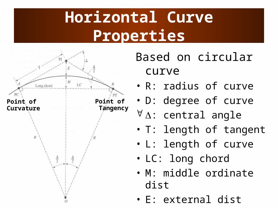
Horizontal Curve Properties
Based on circular curve
• R: radius of curve• D: degree of curve : central angle• T: length of tangent• L: length of curve• LC: long chord• M: middle ordinate dist• E: external dist
Point of Curvature
Point of Tangency
Horizontal Design Iterations
• Design baseline – Curve radius above the minimum– Superelevation and side-friction factor
not exceeding the maximum values
• Design is revised to consider:cost, environmental impacts, sight distances, aesthetic consequences, etc.
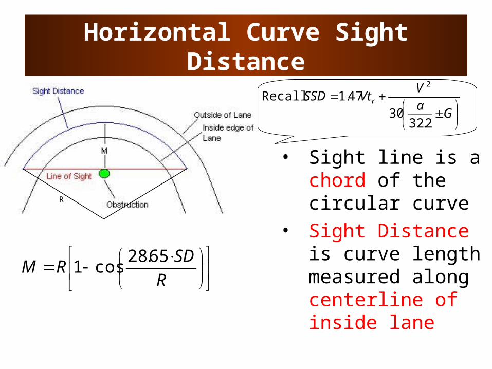
Horizontal Curve Sight Distance
• Sight line is a chord of the circular curve
• Sight Distance is curve length measured along centerline of inside lane
R
SDRM
65.28cos1
R
G
aV
VtSSD r
2.3230
47.12
Recall
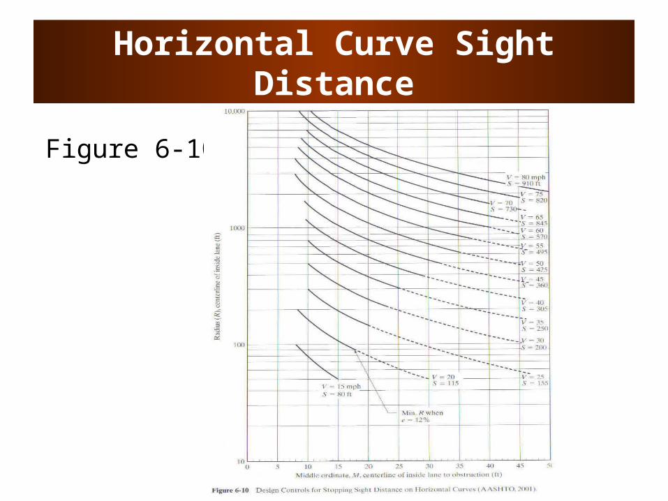
Horizontal Curve Sight Distance
Figure 6-10
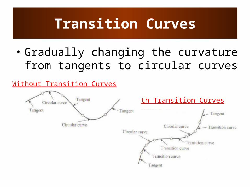
With Transition Curves
Transition Curves
• Gradually changing the curvature from tangents to circular curves
Without Transition Curves
Transition Curves
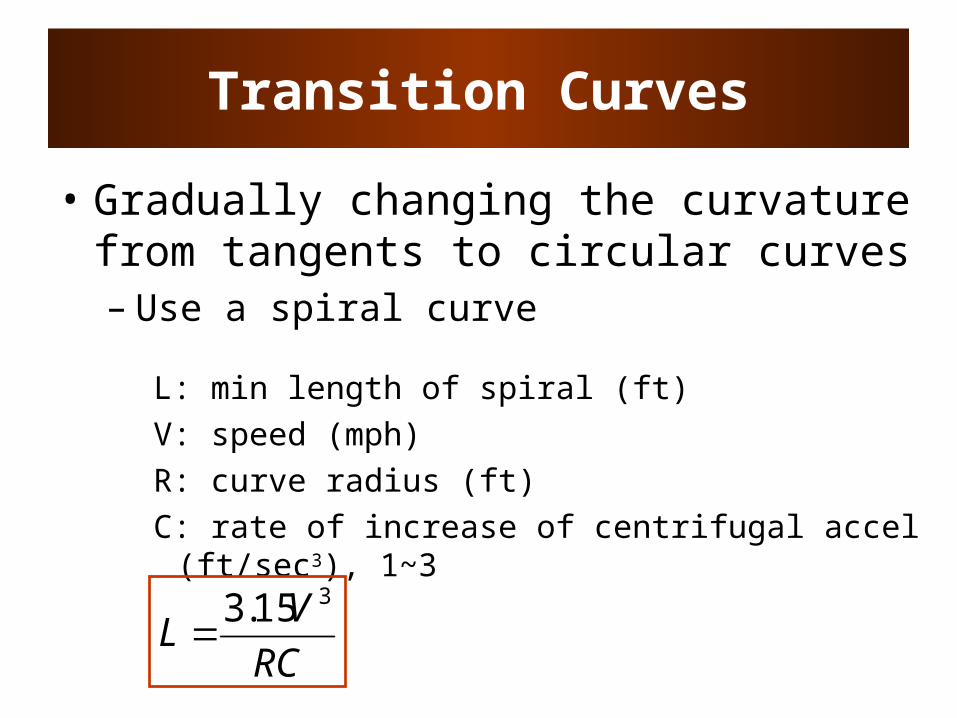
• Gradually changing the curvature from tangents to circular curves– Use a spiral curve
L: min length of spiral (ft)V: speed (mph)R: curve radius (ft)C: rate of increase of centrifugal accel (ft/sec3),
1~3
RC
VL
315.3
Transitional Curves
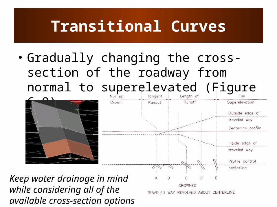
• Gradually changing the cross-section of the roadway from normal to superelevated (Figure 6-9)
Keep water drainage in mind while considering all of the available cross-section options
Vertical Alignment
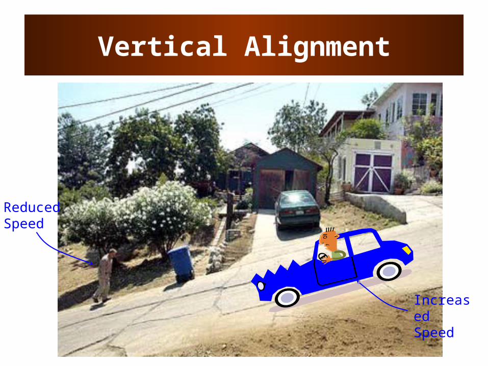
Reduced Speed
Increased Speed
Vertical Alignment
• Grade– measure of inclination or slope, rise over
the run– Cars: negotiate 4-5% grades without
significant speed reduction– Trucks: significant speed changes
• 5% increase on short descending grades• 7% decrease on short ascending grades

Grade Considerations
• Maximum grade – depends on terrain type, road functional class, and design speed
Terrain 60mph 70mph
Level 3% 3%
Rolling 4% 4%
Mountainous 6% 5%
Rural Arterials
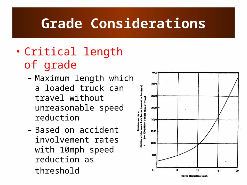
Grade Considerations
• Critical length of grade – Maximum length which
a loaded truck can travel without unreasonable speed reduction
– Based on accident involvement rates with 10mph speed reduction as threshold

Grade Considerations
General Design Speed Reduction

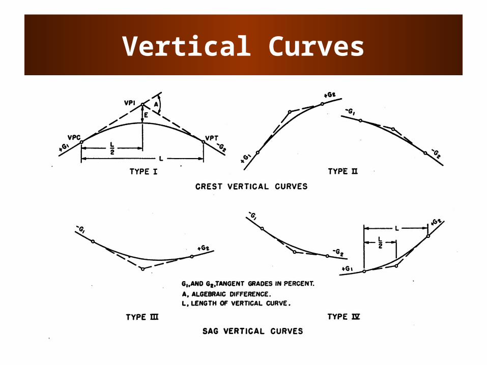
Vertical Curves
• To provide transition between two grades
• Consider– Drainage (rainfall)– Driver safety (SSD)– Driver comfort
• Use parabolic curves• Crest vs Sag curves
Vertical Curves
Vertical Curves
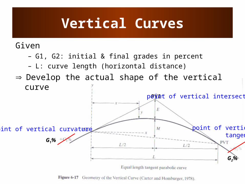
Given – G1, G2: initial & final grades in percent– L: curve length (horizontal distance)
Develop the actual shape of the vertical curve
PVI
point of vertical curvature
point of vertical intersection
point of verticaltangency
G2%
G1%

Vertical Curves
• Define curve so that PVI is at a horizontal distance of L/2 from PVC and PVT
• Provides constant rate of change of grade: L
GGr 12
G1%
G2%
A
L
Axx
GEE PVCP 200100
21
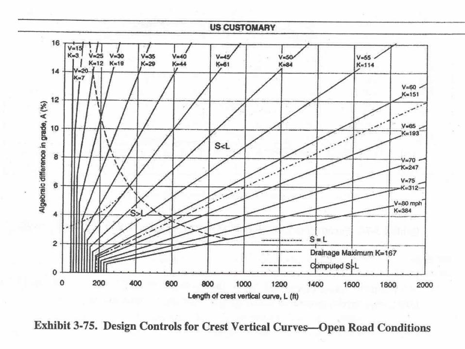
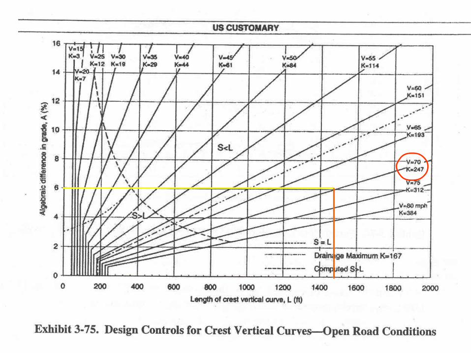
Example
• G1 = 2%
• G2 = -4%
• Design speed = 70 mph• Is this a crest or sag curve?• What is A?
Vertical Curves
• Major control for safe operation is sight distance
• MSSD should be provided in all cases (use larger sight distance where economically and physically feasible)
• For sag curves, also concerned with driver comfort (large accelerations due to both gravitational and centrifugal forces)
Crest Vertical Curves
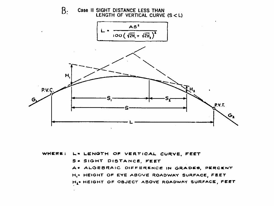
• Critical length of curve, L, is where sight line is tangent to the crest
• Assume driver eye height (H1) = 3.5 ft and object height (H2) = 2.0 ft and S=MSSD

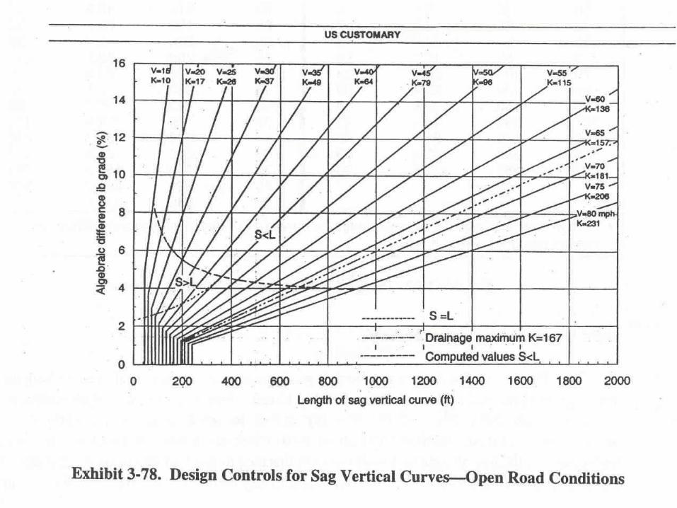
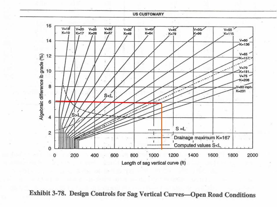
Sag VC - Design Criteria
• Headlight sight distance• Rider comfort• Drainage control• Appearance