Download - Geometric Design (II)
Geometric Design (II)

Learning Objectives
• To calculate minimum radius of horizontal curve
• To understand design concepts for transition curves and compute min length
• To understand the role of SSD in horizontal and vertical design
• To define and apply grade considerations• To develop vertical curves
(Chapter 6.1 ~ 6.4)

• Minimum Curve Radius – Curve requiring the
most centripetal force for the given speed
– Given emax, umax, Vdesign
Horizontal Curve
ue
VR mph
ft
15min
2
)()(
R
Horizontal Curve Properties
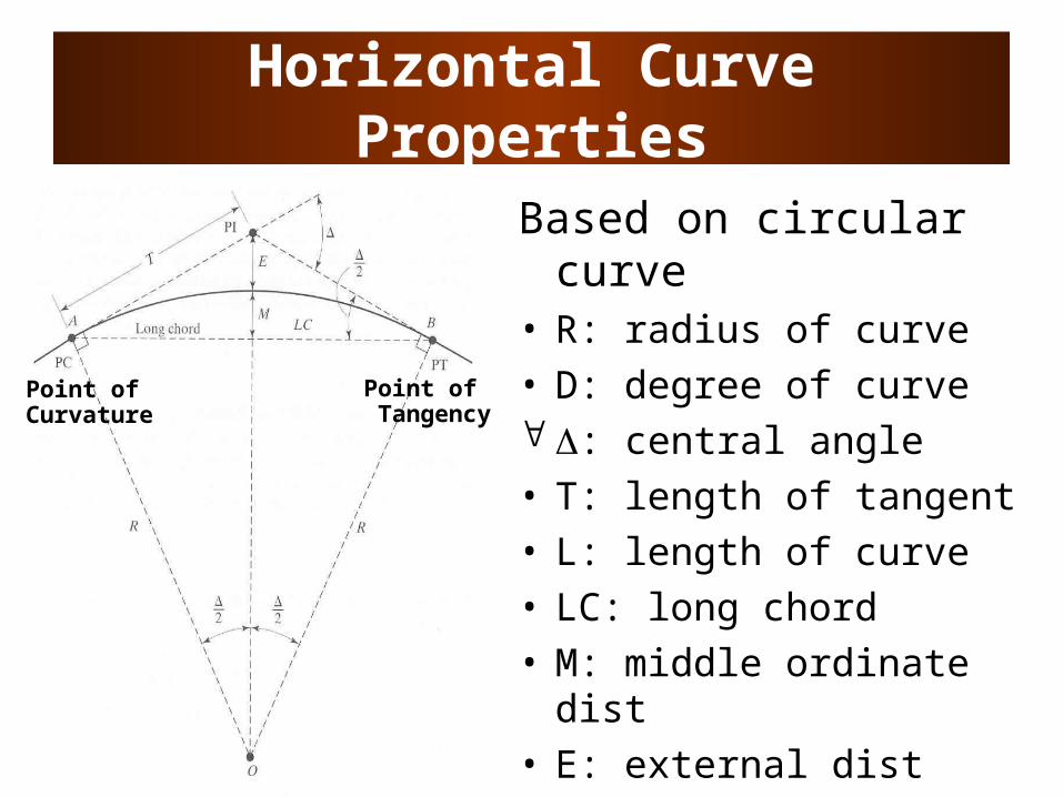
Based on circular curve
• R: radius of curve• D: degree of curve : central angle• T: length of tangent• L: length of curve• LC: long chord• M: middle ordinate dist• E: external dist
Point of Curvature
Point of Tangency
Horizontal Design Iterations
• Design baseline – Curve radius above the minimum– Superelevation and side-friction factor
not exceeding the maximum values
• Design is revised to consider:cost, environmental impacts, sight distances, aesthetic consequences, etc.
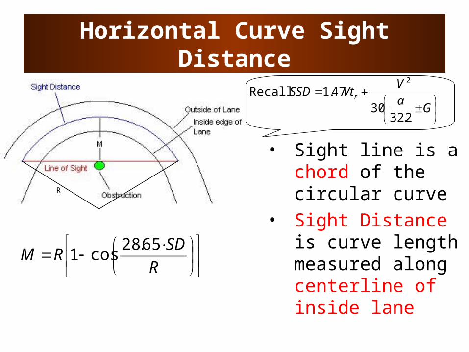
Horizontal Curve Sight Distance
• Sight line is a chord of the circular curve
• Sight Distance is curve length measured along centerline of inside lane
R
SDRM
65.28cos1
R
G
aV
VtSSD r
2.3230
47.12
Recall
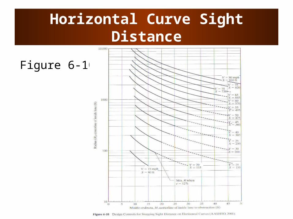
Horizontal Curve Sight Distance
Figure 6-10
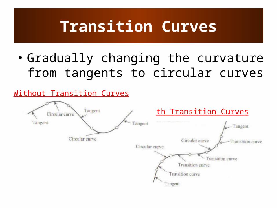
With Transition Curves
Transition Curves
• Gradually changing the curvature from tangents to circular curves
Without Transition Curves
Transition Curves
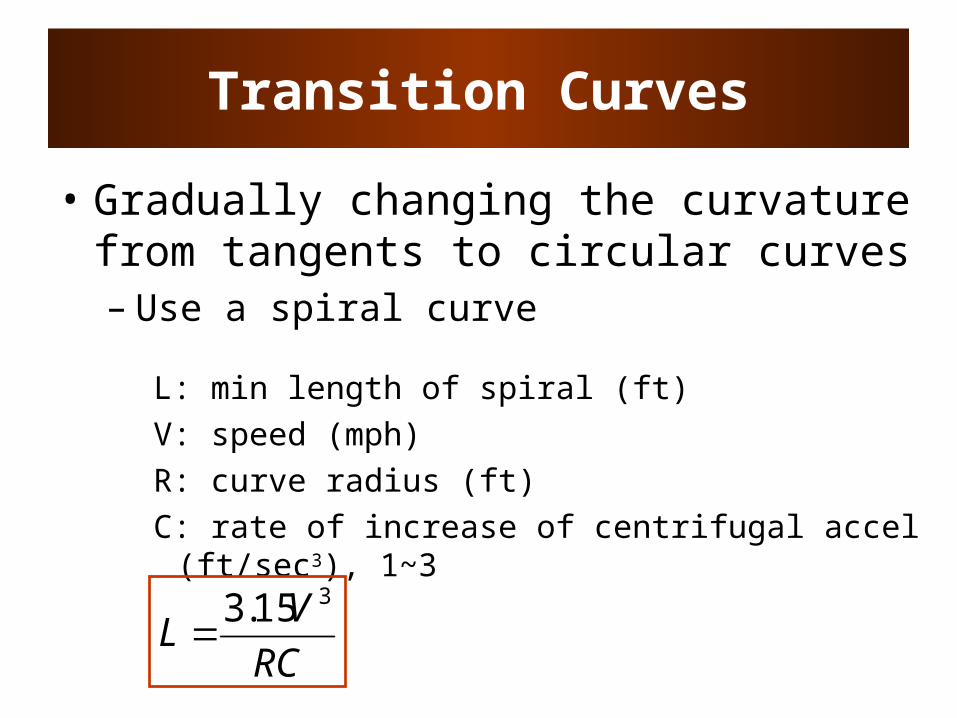
• Gradually changing the curvature from tangents to circular curves– Use a spiral curve
L: min length of spiral (ft)V: speed (mph)R: curve radius (ft)C: rate of increase of centrifugal accel (ft/sec3),
1~3
RC
VL
315.3
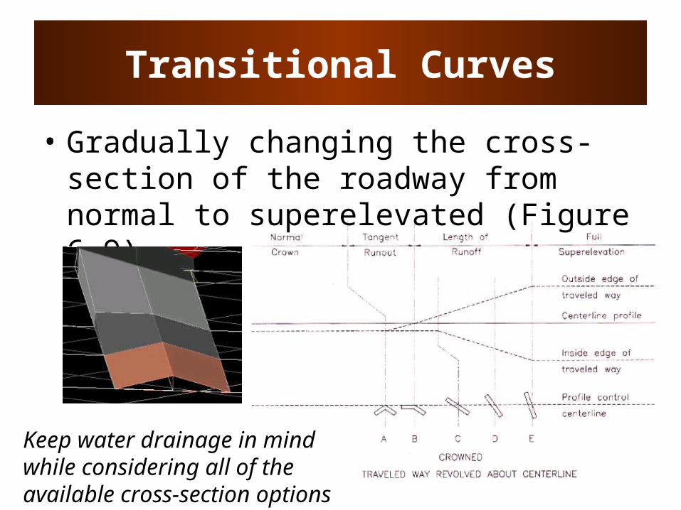
Transitional Curves
• Gradually changing the cross-section of the roadway from normal to superelevated (Figure 6-9)
Keep water drainage in mind while considering all of the available cross-section options
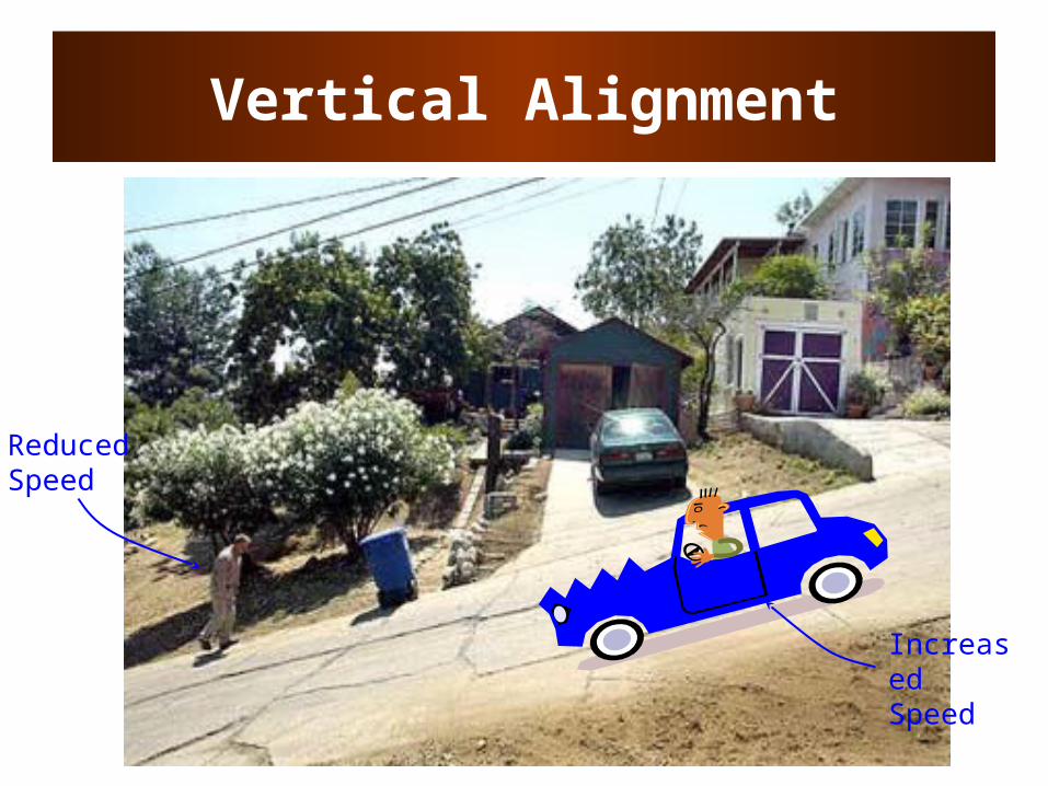
Vertical Alignment
Reduced Speed
Increased Speed
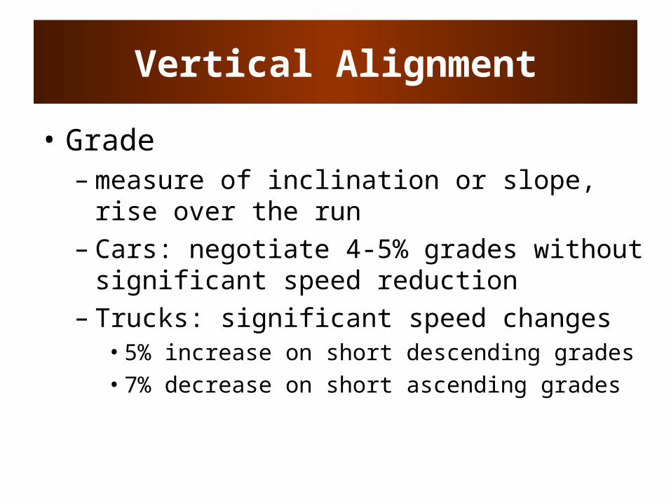
Vertical Alignment
• Grade– measure of inclination or slope, rise over
the run– Cars: negotiate 4-5% grades without
significant speed reduction– Trucks: significant speed changes
• 5% increase on short descending grades• 7% decrease on short ascending grades

Grade Considerations
• Maximum grade – depends on terrain type, road functional class, and design speed
Terrain 60mph 70mph
Level 3% 3%
Rolling 4% 4%
Mountainous 6% 5%
Rural Arterials
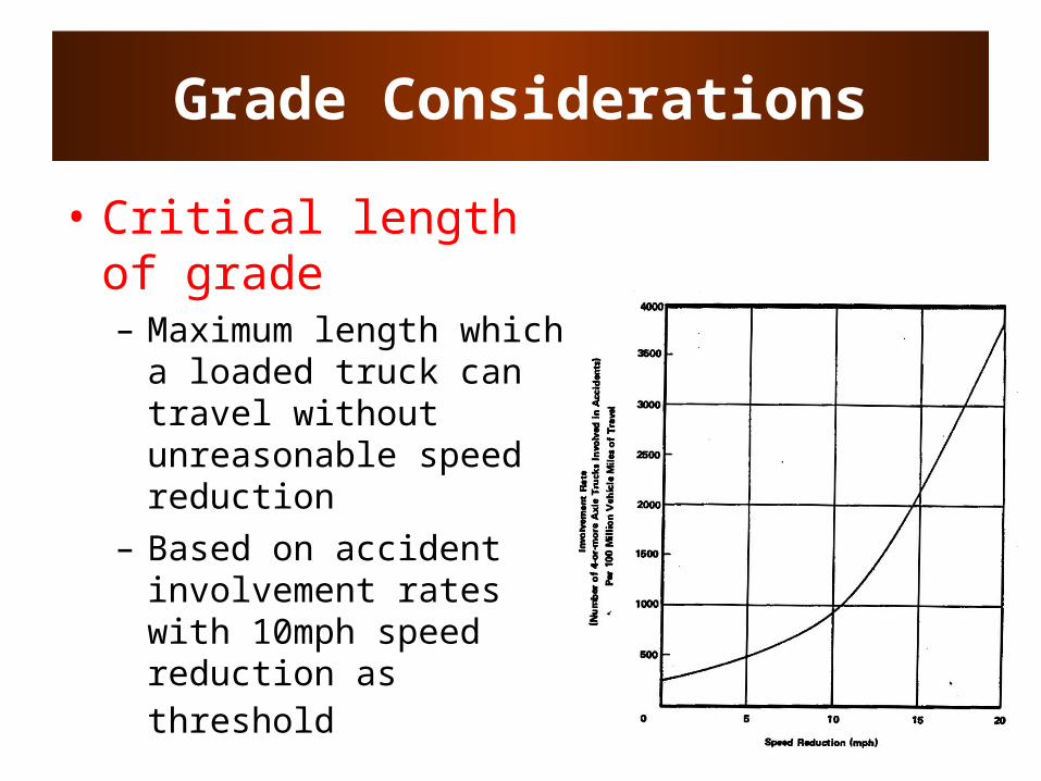
Grade Considerations
• Critical length of grade – Maximum length which
a loaded truck can travel without unreasonable speed reduction
– Based on accident involvement rates with 10mph speed reduction as threshold

Grade Considerations
General Design Speed Reduction

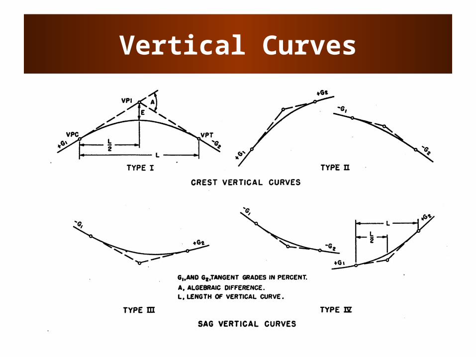
Vertical Curves
• To provide transition between two grades
• Consider– Drainage (rainfall)– Driver safety (SSD)– Driver comfort
• Use parabolic curves• Crest vs Sag curves
Vertical Curves
Vertical Curves
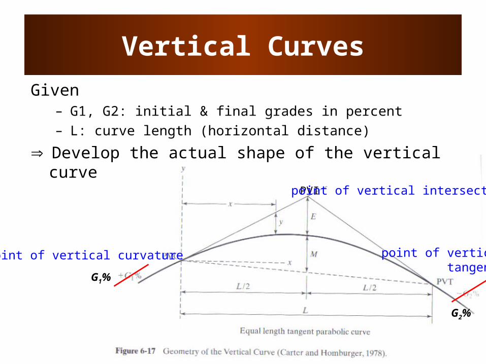
Given – G1, G2: initial & final grades in percent– L: curve length (horizontal distance)
Develop the actual shape of the vertical curve
PVI
point of vertical curvature
point of vertical intersection
point of verticaltangency
G2%
G1%

Vertical Curves
• Define curve so that PVI is at a horizontal distance of L/2 from PVC and PVT
• Provides constant rate of change of grade: L
GGr 12
G1%
G2%
A
L
Axx
GEE PVCP 200100
21
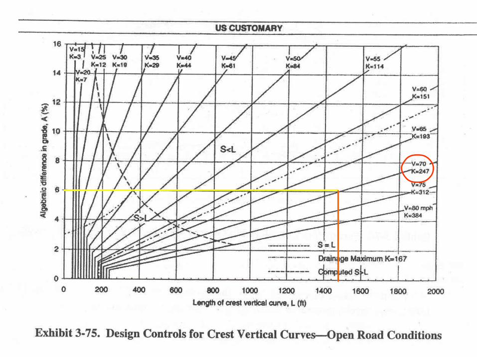
Example
• G1 = 2%
• G2 = -4%
• Design speed = 70 mph• Is this a crest or sag curve?• What is A?
Vertical Curves
• Major control for safe operation is sight distance
• MSSD should be provided in all cases (use larger sight distance where economically and physically feasible)
• For sag curves, also concerned with driver comfort (large accelerations due to both gravitational and centrifugal forces)
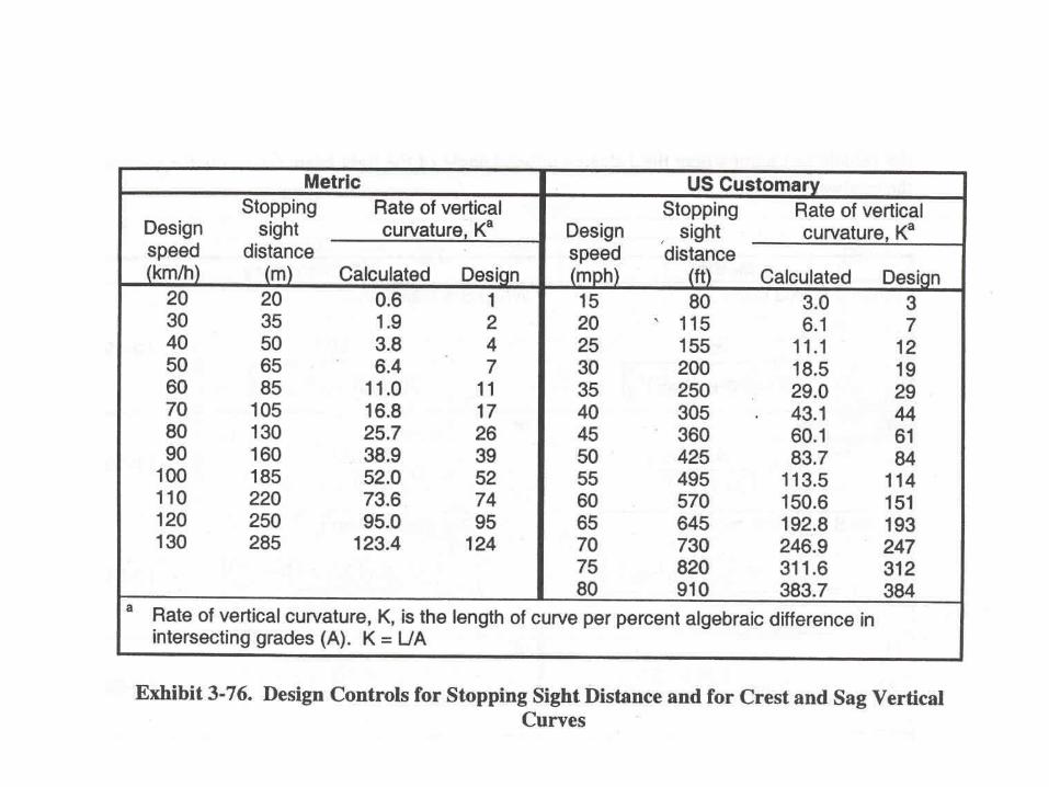
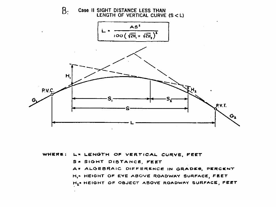
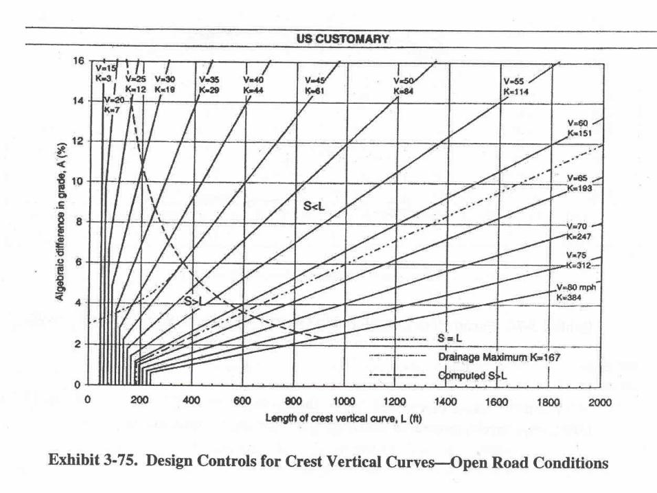
Crest Vertical Curves
• Critical length of curve, L, is where sight line is tangent to the crest
• Assume driver eye height (H1) = 3.5 ft and object height (H2) = 2.0 ft and S=MSSD

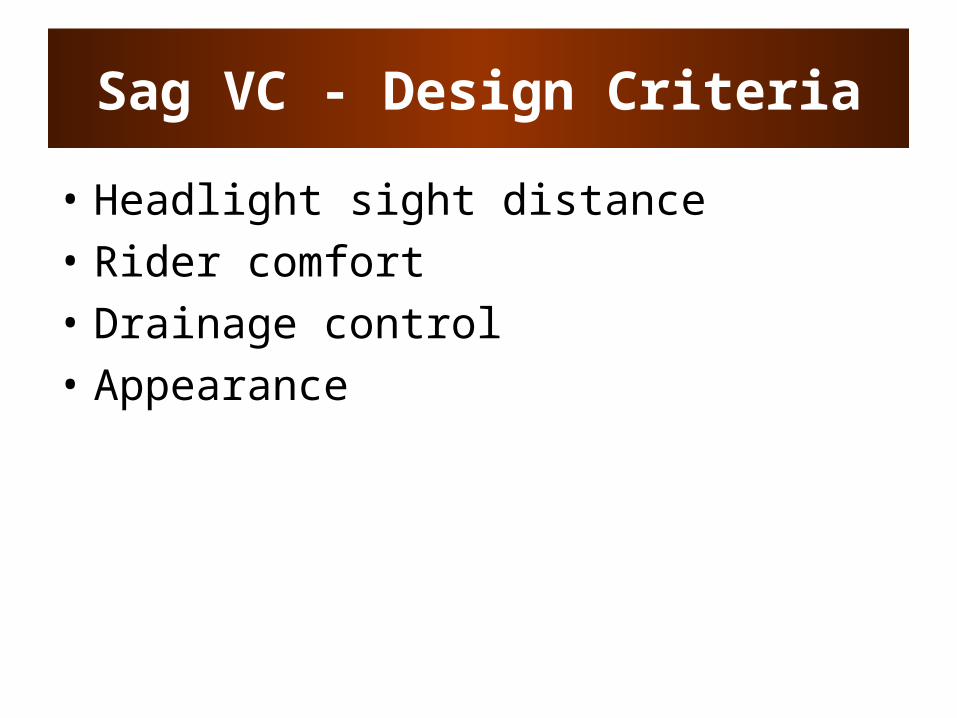
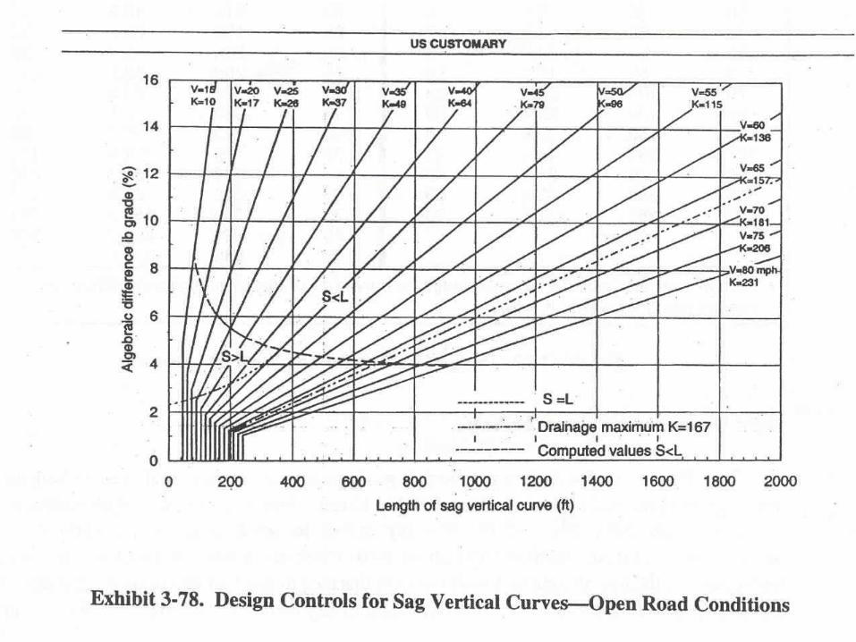
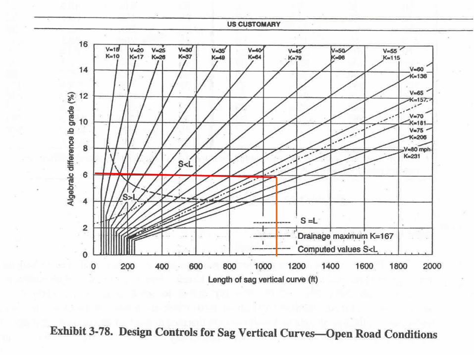
Sag VC - Design Criteria
• Headlight sight distance• Rider comfort• Drainage control• Appearance


![[I.M. Yaglom] Geometric Transformations II](https://cdn.vdocuments.us/doc/165x107/577cc9b41a28aba711a460c4/im-yaglom-geometric-transformations-ii.jpg)


