generic characterization of electrical test ... - wes - recent
TRANSCRIPT

Wind Energ. Sci., 5, 561–575, 2020https://doi.org/10.5194/wes-5-561-2020© Author(s) 2020. This work is distributed underthe Creative Commons Attribution 4.0 License.
Generic characterization of electrical test benches forAC- and HVDC-connected wind power plants
Behnam Nouri1, Ömer Göksu1, Vahan Gevorgian2, and Poul Ejnar Sørensen1
1Department of DTU Wind Energy, Technical University of Denmark, 4000 Roskilde, Denmark2National Renewable Energy Laboratory, Golden, CO, USA
Correspondence: Behnam Nouri ([email protected])
Received: 19 November 2019 – Discussion started: 9 December 2019Revised: 28 February 2020 – Accepted: 31 March 2020 – Published: 6 May 2020
Abstract. The electrical test and assessment of wind turbines go hand in hand with standards and networkconnection requirements. In this paper, the generic structure of advanced electrical test benches, including gridemulator or controllable grid interface, wind torque emulator, and device under test, is proposed to harmonizestate-of-the-art test sites. On the other hand, modern wind turbines are under development towards new features,concerning grid-forming, black-start, and frequency support capabilities as well as harmonic stability and con-trol interaction considerations, to secure the robustness and stability of renewable-energy-based power systems.Therefore, it is necessary to develop new and revised test standards and methodologies to address the new fea-tures of wind turbines. This paper proposes a generic test structure within two main groups, including open-loopand closed-loop tests. The open-loop tests include the IEC 61400-21-1 standard tests as well as the additionalproposed test options for the new capabilities of wind turbines, which replicate grid connection compliance testsusing open-loop references for the grid emulator. In addition, the closed-loop tests evaluate the device undertest as part of a virtual wind power plant and perform real-time simulations considering the grid dynamics. Theclosed-loop tests concern grid connection topologies consisting of AC and HVDC, as well as different electricalcharacteristics, including impedance, short-circuit ratio, inertia, and background harmonics. The proposed testscan be implemented using available advanced test benches by adjusting their control systems. The characteris-tics of a real power system can be emulated by a grid emulator coupled with real-time digital simulator systemsthrough a high-bandwidth power-hardware-in-the-loop interface.
1 Introduction
Wind energy has been one of the most promising renewableenergy sources used worldwide, mostly located onshore. Inaddition, better quality of the wind resource and larger suit-able areas in the sea have made offshore installation a con-siderable choice for wind power plants (WPPs). To date, thetotal installed capacity has reached 592 GW with a 23 GWshare of offshore in 2018 (GWEC, 2018). The new total in-stallations would continue with more than 55 GW each yearby 2023 (GWEC, 2018; Wind Europe, 2018).
The increasing installed capacity of variable renewablegeneration (VRG) has concerned power system operators interms of stability and reliability of the overall power system.
Consequently, new interconnection requirements, standards,and market mechanisms are evolving in various parts of theworld for VRGs, including wind power, to provide varioustypes of essential reliability services to the power systems –the role that has been typically reserved for conventional gen-eration (NERC, 2015). Furthermore, the industry has focusedon collaboration and harmonization to achieve the technicaland economic benefits of a uniform technology and market,especially in Europe (IRENA, 2018; Sørensen et al., 2019).In this way, the European Commission has regulated interna-tional requirements for AC- and HVDC-connected power-generating modules as well as HVDC systems (Commis-sion Regulation 631, 2016; Commission Regulation 1447,2016). Consequently, updated compliance test standards are
Published by Copernicus Publications on behalf of the European Academy of Wind Energy e.V.

562 B. Nouri et al.: Generic characterization of electrical test benches for wind power plants
required to ensure the power quality and stable operation ofVRGs, especially WPPs. The development of European net-work codes and IEC standards are two of best harmonizationpractices in wind energy.
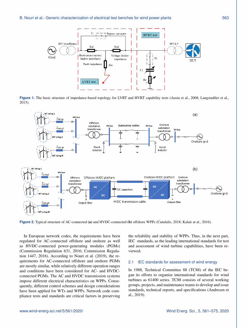
Compliance test methods are in line with relevant gridconnection requirements and standards. Furthermore, windtechnology has been matured by research, development, anddemonstrations in industrial test sites and laboratories. Fig-ure 1 illustrates the basic compliance test equipment, whichhad been proposed for low-voltage ride-through (LVRT) ca-pability test in Ausin et al. (2008) and is addressed as an ex-ample in IEC 61400-21-1 (2019). Recently, this structure hasbeen adapted for high-voltage ride-through (HVRT) capabil-ity tests as well (Langstadtler et al., 2015). In this topology,the voltage divider impedances (Xsd and Xsc) are used forthe LVRT test of the device under test (DUT). Also, the par-allel capacitors (CL) in series with damping resistors (Rd)are used for the HVRT test. Xsl is used to limit the effectof tests on the utility grid by limiting the current flow fromthe utility grid during the test. The test apparatus structureshown in Fig. 1 has proven to be a useful tool in the earlystages of grid integration research and criticizing of utility-scale wind power. However, it has certain fundamental limi-tations, such as dependence on a stronger point of intercon-nections, uncontrollable dynamic change of impedance dur-ing testing, and inability to replicate most of AC grid char-acteristics (Ausin et al., 2008; Asmine and Langlois, 2017;Gevorgian and Koralewicz, 2016).
Primarily, power quality and transient performance duringfaults have been essential aspects, which needed to be testedand verified. However, by increasing trends towards 100 %VRG-based grids, the VRGs are required to be developedand featured by advanced capabilities to secure the robust-ness and reliability of such grids. The operation and stabilityof VRG-based power systems depend on the interoperabilityand capabilities of the individual power-generating systemssuch as wind turbines (WTs). In this way, the state-of-the-artWTs are under development towards advanced features, es-pecially grid-forming and black-start capabilities. These newcapabilities necessitate appropriate test and assessment stan-dards in the near future (Langstadtler et al., 2015; Asmineand Langlois, 2017; Gevorgian and Koralewicz, 2016). In ad-dition, by increasing wind power installations, it is requiredto study the rising challenges such as harmonic resonancesand control interactions of WPPs in connection to differenttypes of AC and HVDC transmission systems according toHertem et al. (2016), Zeni et al. (2016), and Buchhagen etal. (2015). Thus, it is essential to adapt or define new reg-ulations, standards, and compliance test methods to analysethe developments and issues regarding wind energy. To date,several standards and recommendations such as IEC, IEEE,DNV GL, and CIGRE have been published for design, sim-ulation, operation, and testing of electrical aspects of WTs(IEC 61400-21-1, 2019; IEEE Std. 1094, 1991; DNVGL-ST-0076, 2015; CIGRE Technical Brochure 766, 2019). The
IEC standards as the leading international standards for thetest and assessment of wind turbines have been reviewed inthis paper.
In this paper, the authors aim to extend the state-of-the-artdevelopments in wind energy towards harmonized test meth-ods and propose additional test options to the standard teststo extend the applications of advanced industrial test benchesregarding operation and stability assessment of WTs as wellas WPPs. In Sect. 2, grid connection compliance tests, in-cluding typical grid connection topologies, IEC standards,and electrical test levels, have been introduced. Section 3 de-scribes the state-of-the-art industrial test benches and illus-trates the generic structure of converter-based test equipment.In Sect. 4, the electrical characteristics of different grids tobe emulated in a test site have been studied and proposed.Finally, Sect. 5 proposes the generic structure of test optionsconsisting of the recommended tests in IEC standards as wellas proposed additional test options for open-loop tests as wellas closed-loop tests for WTs and WPPs.
2 Grid connection compliance tests
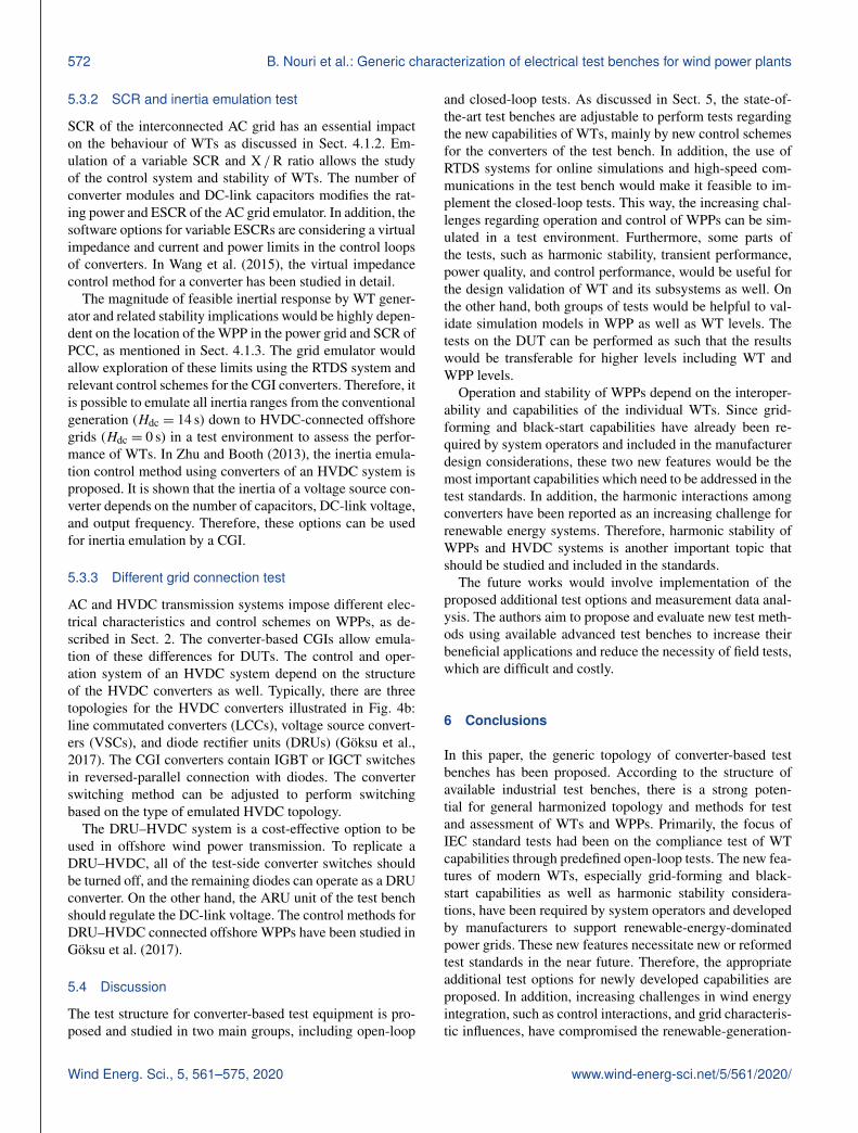
The wind power can be transmitted through either AC orHVDC transmission systems to the main AC grids. In ad-dition, there is an increasing trend to develop WPPs in off-shore areas because of the higher power capacity of offshorewinds and limited onshore sites (Wind Europe, 2018; Cutu-lulis, 2018; Kalair at al., 2016). According to the EuropeanWind Energy Association (EWEA) (Pierri et al., 2017), po-tentially, European offshore wind power can supply 7 timesEurope’s demand. Figure 2 illustrates a typical structure forAC and HVDC connections of offshore WPPs. As shownin Fig. 2a, the AC-connected offshore WPP connects tothe main onshore grid through high-voltage submarine ca-bles and transformers. In addition, the shunt inductors arerequired to dampen the possible over-voltage phenomenacaused by the capacitive effect of the AC cables. The typi-cal structure of an HVDC-connected offshore WPP is illus-trated in Fig. 2b, which consists of HVDC transmission ca-bles, transformers, AC–DC converters, and harmonic filtersof the converters. An HVDC connection has economic ad-vantages for long distances, especially in the case of offshoreWPPs (Hertem et al., 2016; Cutululis, 2018; Kalair at al.,2016). Hence, the recent interest in wind energy has been fo-cused on offshore WPPs, and HVDC systems are requireddue to long distances from the main AC grids. The collec-tor system voltages in AC- and HVDC-connected WPPs (i.e.medium-voltage (MV) buses in Fig. 2) are typically 33 and34.5 kV in Europe and the US, respectively. Recently, several66 kV collector systems in offshore WPPs have been demon-strated. Therefore, 66 kV seems to be a general trend in col-lector system design in the offshore wind industry (Wiser etal., 2018).
Wind Energ. Sci., 5, 561–575, 2020 www.wind-energ-sci.net/5/561/2020/
B. Nouri et al.: Generic characterization of electrical test benches for wind power plants 563
Figure 1. The basic structure of impedance-based topology for LVRT and HVRT capability tests (Ausin et al., 2008; Langstadtler et al.,2015).
Figure 2. Typical structure of AC-connected (a) and HVDC-connected (b) offshore WPPs (Cutululis, 2018; Kalair at al., 2016).
In European network codes, the requirements have beenregulated for AC-connected offshore and onshore as wellas HVDC-connected power-generating modules (PGMs)(Commission Regulation 631, 2016; Commission Regula-tion 1447, 2016). According to Nouri et al. (2019), the re-quirements for AC-connected offshore and onshore PGMsare mostly similar, while relatively different operation rangesand conditions have been considered for AC- and HVDC-connected PGMs. The AC and HVDC transmission systemsimpose different electrical characteristics on WPPs. Conse-quently, different control schemes and design considerationshave been applied for WTs and WPPs. Network code com-pliance tests and standards are critical factors in preserving
the reliability and stability of WPPs. Thus, in the next part,IEC standards, as the leading international standards for testand assessment of wind turbine capabilities, have been re-viewed.
2.1 IEC standards for assessment of wind energy
In 1988, Technical Committee 88 (TC88) of the IEC be-gan its efforts to organize international standards for windturbines as 61400 series. TC88 consists of several workinggroups, projects, and maintenance teams to develop and issuestandards, technical reports, and specifications (Andresen etal., 2019).
www.wind-energ-sci.net/5/561/2020/ Wind Energ. Sci., 5, 561–575, 2020

564 B. Nouri et al.: Generic characterization of electrical test benches for wind power plants
2.1.1 IEC standards for electrical tests
Initially, TC88 focused on power performance (i.e. powercurve) tests and structural and mechanical design. The workson electrical tests started in 1997 as IEC 61400-21 series bythe working group WG21.
The second edition of IEC 61400-21 was published in2008 to cover the definition and specifications for measure-ment and assessment of power quality characteristics forwind turbines. Currently, IEC TC88 WG21 is working onfour new documents for the IEC 61400-21 series, where thetitle is changed from power quality characteristics to electri-cal characteristics appreciating that not only power qualitycharacteristics are included (Andresen et al., 2019). To date,there is no IEC standard for testing the electrical character-istics of WPPs, but only for testing single WTs. Regardingthe grid connection compliance assessment, the evaluationof performance and quality of WPPs is based on measure-ments, simulations, and model validation tests (Ausin et al.,2008; Asmine and Langlois, 2017; Andresen et al., 2019).
Recently, IEC 61400-21-1 has been published and re-placed the second edition of 61400-21. IEC 61400-21-1specifies test methods for electrical characteristics of windturbines (IEC 61400-21-1, 2019). Also, IEC 61400-21-2specifies test methods for electrical characteristics of WPPs(Andresen et al., 2019). Concerning the growing issues re-garding harmonics in WPPs, IEC 61400-21-3 aims to focuson harmonic modelling as a technical report. IEC TR 61400-21-3 provides a starting point for the required frequency–domain modelling of wind turbines (IEC TR 61400-21-3,2019). Furthermore, IEC 61400-21-4 recommends a tech-nical specification for component and subsystem tests (An-dresen et al., 2019). IEC 61400-21-1 and IEC 61400-21-3were published in 2019, while 61400-21-2 and 61400-21-4may be published in 2021.
In addition, the IEC 61400-27 series specifies standard dy-namic electrical simulation models for wind power genera-tion. The first edition of IEC 61400-27-1, published in 2015,specifies generic models and validation procedures for windturbine models. Furthermore, the next edition is under devel-opment to expand the scope towards WPP models in additionto the WT models (Sørensen, 2019). The next edition con-sists of two parts: IEC 61400-27-1 specifying generic modelsfor both WTs and WPPs and 61400-27-2 specifying valida-tion procedures.
2.1.2 Electrical test levels
According to the IEC-61400-21-1 (IEC 61400-21-1, 2019),the electrical characteristics to be simulated and validated forwind turbines consist of five different categories: power qual-ity aspects, steady-state operation, control performance, tran-sient performance or fault ride-through capability, and gridprotection. The electrical characteristics of WTs can be mea-sured and tested at different levels. The test levels consist of
component test level (such as capacitors and switches), sub-system test level (such as nacelle and converter), field mea-surement at wind turbine level (or type test), and field test ormeasurement at WPP level (IEC 61400-21-1, 2019). Further-more, the WT level tests can be split into two subcategories:(a) testing of the full drivetrain connected to a low-voltagetest bench and (b) testing of the full drivetrain connected to amedium-voltage test bench via the WT’s transformer witha full set of protection and switchgear (Koralewicz et al.,2017). The second option is closer to reality since it includesimpacts of transformer impedance and configuration and pro-tection settings on transient performance. In IEC 61400-21-1(2019), an overview of the required and optional test levelsfor different test and measurement requirements is provided.
Today, to have a flexible and economical solution for gridconnection compliance tests and model validations, the trendis to perform tests at lower levels, such as WT and sub-system levels. The test results concern wind farm develop-ers and system operators in terms of WPP model validationand grid connection compliance and WT manufacturers interms of WT design and simulation model validations. Thisway, the results of tests are considered to be transferable anduseful for the assessment of WTs as well as WPPs and de-veloped simulation models (Ausin et al., 2008; Zeni et al.,2016; Koralewicz et al., 2017). However, in some cases per-forming field tests and measurements is still necessary asreported in Asmine and Langlois (2017). Accordingly, theHydro-Québec TransÉnergie experience (Asmine and Lan-glois, 2017) regarding the inertial response has shown thatan adequate evaluation of the inertial response cannot be per-formed accurately at WT level and should include evalua-tions at the WPP level. As another example, the power qual-ity assessment of WPPs is either assessed using scaling rulesof WT test results or accomplished by the assessment of on-line measurement data. The online monitoring is achievedduring the first year of operation of the WPP (Asmine andLanglois, 2017). However, the increasing challenges, such asharmonic resonances, grid interactions, and voltage and fre-quency stability issues, have proven the need for more ex-tended analysis and assessment of WPPs. In this regard, thegeneric converter-based test bench and possible test and as-sessment solutions for WTs and WPPs are proposed in thenext parts of this paper.
3 Generic converter-based test bench
Different electrical test benches as controllable grid inter-faces (CGIs) have been reported for grid dynamics emula-tion in Ausin et al. (2008), Gevorgian and Koralewicz (2016),Espinoza and Carlson (2019), Espinoza et al. (2015), andYang et al. (2012). The impedance-based test equipment inFig. 1 is only intended for the fault ride-through capabilitytests. A more advanced and flexible topology is a full-powerconverter-based CGI, which is shown in Fig. 3. This topol-
Wind Energ. Sci., 5, 561–575, 2020 www.wind-energ-sci.net/5/561/2020/

B. Nouri et al.: Generic characterization of electrical test benches for wind power plants 565
ogy has been used in the latest industrial test benches and isstudied in the next parts of this paper.
In MEGAVIND (2016), a mapping of global test anddemonstration facilities serving the wind industry in Eu-rope and the US is presented by topic and location. Accord-ingly, most of the latest industrial test benches are based onpower electronic converters. Converter-based test equipmentprovides emulation of unlimited test scenarios applicable topower systems of various sizes (sizable interconnected powergrids, island systems, or mini-grids) operating at both 50and 60 Hz, with full controllability over electrical character-istics of emulated grids. The generic schematic diagram of aconverter-based test rig is illustrated in Fig. 3. Generally, aconverter-based test bench consists of three main parts: de-vice under test (DUT), wind torque emulator, and grid emu-lator or CGI. In Fig. 3, the DUT is a WT nacelle. The CGIcan also be used for testing of complete WTs, in which casethe wind torque emulator in Fig. 3 is not required.
In Table 1, the specifications for some remarkable ad-vanced test sites are illustrated. As it is presented in Fig. 3,the application of multilevel drive converter modules in par-allel connections is a typical topology to establish a medium-power and medium-voltage source as grid and wind torqueemulators (Averous et al., 2017; Gevorgian, 2018; Jersch,2018; Rasmussen, 2015; Tuten et al., 2016). The multilevelconverters, such as three-level neutral point clamped (3L-NPC) and H-bridge topologies, are developed to achievehigher efficiency and lower harmonic distortion rather thanconventional two-level converters, and they reduce the sizeof harmonic filtering and undesired interference.
According to the Table 1, a group of test sites such asavailable test setups in NREL (National Renewable EnergyLaboratory, USA), Fraunhofer IWES (Fraunhofer Institutefor Wind Energy Systems, Germany), and CENER (NationalRenewable Energy Centre, Spain) have used three-level NPCdrive converters developed by the ABB company. The ABBdrive converters are controlled by the direct torque control(DTC) method with integrated gate-commutated thyristor(IGCT) switches (ABB, 2018). On the other hand, in the sec-ond group, with LORC (Lindø Offshore Renewables Cen-ter, Denmark) and Aachen (RWTH Aachen University, Ger-many), the converters are three-level NPCs developed by theGE company (General Electric). GE’s medium-power driveconverters are controlled by advanced vector control (AVC)using insulated gate bipolar transistor (IGBT) switches (GE,2018). In addition, different types of converters would beutilized in a test site. For instance, the drivetrain test fa-cility at Clemson University was established using multi-level H-bridge drive converters developed by the TECO-Westinghouse company (Tuten et al., 2016). Each converterdeveloper utilizes different components, control methods,and interface algorithms. However, all of the test benchesshould be able to perform tests according to the standardsand research objectives, and minimize the effect of non-idealemulation of a real test environment for the DUT. In most of
the test sites, a real-time digital simulation (RTDS) system isused to get to a dynamic online model of the grid as well asthe overall system.
The main limitation of converter topology shown in Fig. 3,as well as any converter-based test rigs, is limited over-current capability. This constraint can be addressed by over-sizing the MVA rating of the test side converter similar towhat was done in NREL’s CGI (7 MVA continuous powerrating but capable of operating at 40 MVA short-circuit ca-pacity for 2 s; Gevorgian, 2018) as given in Table 1. Over-sizing of converters for this purpose is costly but is necessaryfor LVRT testing of doubly fed induction generator (DFIG)WTs, which can produce higher levels of short-circuit cur-rent contribution. In this regard, high-power and short-circuitcapacity are achieved by parallel connection of converters ineach converter unit as indicated by N(ARU) and M(AGE) inTable 1.
Furthermore, the majority of companies have plans to de-velop their sites as such to be able to test a wide rangeof WTs, including medium-power to higher-power ratings,which are mostly for offshore applications. According toPietilaeinen (2018), the new trends in the development ofgrid simulators are as follows:
– higher-power ratings, up to 24 MW rating and 80 MVAshort-circuit power;
– grid impedance emulation, virtual impedance emulationusing the converters’ control system;
– higher bandwidth for harmonic injections, up to 25thor even 100th harmonic injection for harmonic stabilitytests;
– extension of use for component and subsystem tests,and mobility of test equipment to perform field tests.
The three main parts of the generic converter-based testrig, which is shown in Fig. 3, are introduced as follows.
3.1 Device under test
The device under test (DUT) can be one or more of a wholeWT or its subsystems such as a nacelle consisting of con-verters and a generator, or only converters of a WT. Today,WTs are mainly full-converter or DFIG types in new devel-oped WPPs. The main objective of test facilities is to per-form compliance electrical and mechanical tests in the WTand subsystem test levels on the DUT.
3.2 Grid emulator
The grid emulator or CGI consists of two back-to-back con-verter units to emulate real grid characteristics for the DUT,as is shown in Fig. 3. The first converter unit is connectedto the utility grid through a transformer, which is called the
www.wind-energ-sci.net/5/561/2020/ Wind Energ. Sci., 5, 561–575, 2020

566 B. Nouri et al.: Generic characterization of electrical test benches for wind power plants
Figure 3. Proposed generic schematic diagram of a converter-based test bench.
Table 1. Comparison of different concepts applied in industrial test benches.
Test CGI Short-circuit Torque emulator Converter type N(ARU)a M(AGE)b Converter RTDScentre rating capacity rating control
LORC 15 MVA 30 MVA 13 MW 3L-NPC GE (IGBT) 2 2 AVC noAachen 3.5 MVA 7.5 MVA 4 MW 3L-NPC GE (IGBT) 1 1 AVC yesNREL 7 MVA 40 MVA 5 MW 3L-NPC ABB (IGCT) 1 4 DTC yesF. IWES 15 MVA 44 MVA 10 MW 3L-NPC ABB (IGCT) 2 3 DTC yesCENER 9 MVA 18 MVA 9 MW 3L-NPC ABB (IGCT) 1 2 DTC yesClemson 15 MVA 20 MVA 7.5 and 15 MW H-bridges TECO-W 2 2 AVC yes
a N(ARU): number of ARU modules. b M(AGE): number of AC grid emulator modules.
“active rectifier unit (ARU)”. Generally, the control objec-tive for the ARU is to regulate the DC-link voltage in a ref-erence value within an acceptable deviation range. The refer-ence value for DC link depends on the type and objectives ofthe test. Thus, the ARU should perform as a current sourceto exchange active and reactive power between the DC-linkcapacitors and the utility grid.
The second converter unit is connected to the DUTthrough a transformer, which is called the “AC grid emula-tor”. The controller of the AC grid emulator is designed toemulate a realistic grid dynamic and steady-state behaviours.In addition, to have an acceptable range of total harmonicdistortion and to prevent unwanted harmonics and noise in-terference in the setup, appropriate passive filters on bothsides of the converters have been considered. Also, in somecases, active filtering methods are implemented by additionalcontrol strategies such as selective harmonic elimination andinterleaved harmonic elimination methods, to decrease theneed for the large passive filters (Gevorgian and Koralewicz,2016; Averous et al., 2017). Thus, by this structure, the powerflow in the CGI is controlled. Meanwhile, the assessment ofDUT behaviour would be accomplished by online simula-tions, measurements, and data analysis.
3.3 Wind torque emulator
Assessment of electromechanical interactions of WTs can beachieved by using the wind torque emulator part in the testbench. As is illustrated in Fig. 3, the wind torque emulatorwould either be connected directly to the DC link of CGI asa common DC link, or have a separate ARU unit connectedto the utility grid. A separate DC link for the wind torqueemulator enables an independent control system and reducesthe side effects of power electronic converters on each othersuch as harmonic interference, DC-link voltage deviations,and control interactions.
The wind torque emulator is a prime mover system con-sisting of a drive converter connected to an AC or DC motor.This way, the characteristics of the missing WT rotor in thelaboratory environment would be recreated. This objective isnecessary for hardware-in-the-loop (HiL) testing of DUTs,especially for the tests, such as the LVRT capability test, inwhich a realistic emulation of rotor torque for the DUT’smain shaft is required. This requirement implies an accurateemulation of steady-state and dynamic torque characteristicsof the rotor, including the rotor inertia and its eigenfrequen-cies, as studied in Neshati et al. (2016).
The drive system converts the electrical power to the me-chanical power for the shaft of the generators. On the other
Wind Energ. Sci., 5, 561–575, 2020 www.wind-energ-sci.net/5/561/2020/

B. Nouri et al.: Generic characterization of electrical test benches for wind power plants 567
hand, the generators convert the mechanical power to theelectrical power in connection to the CGI. In this way, thepower flow circulates through the utility grid, wind torqueemulator, and grid emulator. The first constraint of this powercirculation is the manageable power loss. In addition, the sec-ond constraint is required maximum power flow during theLVRT capability test. During voltage sag emulation by theAC grid emulator, the ARU has to provide the active powerto the wind power emulator. Thus, the maximum requiredpower flow and power losses during tests should be consid-ered in design of converter units and their cooling system.
4 Test bench characteristics
The advanced specification of converter-based test equip-ment facilitates performing grid connection compliance testsand gives the opportunity to analyse, predict, and eliminatethe possible challenges facing wind energy technology. Inthis part, electrical characteristics of an emulated AC gridby a converter-based test site have been studied.
4.1 Emulated grid characteristics
The characteristics of a real power system that test articleis exposed to at its point of common coupling (PCC) canbe emulated by CGI coupled with RTDS through a power-hardware-in-the-loop (PHiL) interface. The AC grid emula-tion can provide flexible options regarding the electrical char-acteristics of power grids, including impedance, short-circuitratio, inertia, and background noise.
4.1.1 Grid impedance
One of the main differences between AC and HVDC con-nections is the structure of equivalent grid impedance asshown in Fig. 2. Especially in AC-connected offshore WPPswith long AC export submarine cables, the grid impedance ishigh and frequency-dependent, which can create resonancesand instability (Kocewiak et al., 2013). In addition, in thecase of onshore AC connections, the main issue would beconsiderably high grid impedance for long-distance WPPs.Typically, for AC offshore connections, the grid impedancewould be considered capacitive, while for AC onshore con-nections it would be high inductive impedance. In addition,regarding HVDC-connected offshore WPPs, the equivalentresistance of the grid impedance is low. Thus, the naturalresonance damping capability in such grids is low, and theconverters of WTs are prone to interact with the convert-ers of the HVDC system. Therefore, the harmonic stabilityof an HVDC connection is very vulnerable. The interactionsamong grid impedance, converter controllers, and passive fil-ters can cause instability and resonance issues in a WPP aswell as HVDC station (Buchhagen et al., 2015; Kocewiak etal., 2013; Sowa et al., 2019; Beza and Bongiorno, 2019).
In a synchronous-generator-based grid, large electricalloads facilitate the grid stability during dynamics and res-onances. However, in such grids, the sub-synchronous con-trol interactions between WTs and transmission lines in se-ries with voltage compensation capacitors, which is investi-gated in Chernet et al. (2019), are still a serious concern. Theimpedance of the test bench can be arranged as such to studythe sub-synchronous control interaction as well. Therefore,it is essential to consider the emulation of grid impedancecharacteristics in the test environment and test results. Thecontrollable dynamic impedance emulation is another advan-tage of a converter-based grid emulator (in comparison to thevoltage divider test equipment shown in Fig. 1), which im-poses fewer uncertainties regarding equivalent impedance tothe point of connection of the DUT.
4.1.2 Short-circuit ratio
As the AC system impedance increases, the voltage magni-tude of the AC system becomes even more sensitive to thepower variations at the PCC. This dependency is usually de-termined by the short-circuit ratio (SCR), which is a ratioof the short-circuit capacity (Ssc) versus the rated power ofthe AC grid at PCC (Pnpcc) as illustrated in Eqs. (1) and (2)(IEEE Std. 1204, 1997).
Ssc =V 2
pcc
Zgrid(1)
Here Zgrid is the equivalent impedance of the grid, and Vpccis the nominal phase-to-phase voltage at PCC.
SCR =Ssc
Pnpcc(2)
The investigations in Fan and Miao (2018) have shown thata weak grid interconnection of an AC-connected WPP (e.g., ERCOT, USA) can lead to poorly damped or undampedvoltage oscillations. The SCR evaluation for an HVDC-connected AC grid is defined as an effective short-circuit ra-tio (ESCR). ESCR is the ratio of the short-circuit power ofthe AC grid along with HVDC converter filters and capaci-tor banks (S(AC+HVDC)) to the rated power of the HVDC link(PHVDC), as presented in Eq. (3). Typical weak HVDC con-nections have an ESCR less than 2.5 (Yogarathinam et al.,2017).
ESCR =S(AC+HVDC)
PHVDC(3)
The studies in Zhou et al. (2014) have concluded thatthe operation of the HVDC converter is greatly affected bythe angle of the AC grid impedance, converter phase-lockedloop (PLL) parameters, and AC system strength. A converter-based test bench has a similar structure to an HVDC connec-tion system with two back-to-back converters. Thus it canbe used to emulate an HVDC system with different ESCRs
www.wind-energ-sci.net/5/561/2020/ Wind Energ. Sci., 5, 561–575, 2020

568 B. Nouri et al.: Generic characterization of electrical test benches for wind power plants
for the DUT. These emulations would be implemented byadjusting the control system, modular selection of the CGIconverters, and reconfiguration of output filter components,especially in a test setup consisting of an RTDS system.
4.1.3 Grid inertia
The grid inertia is another important criterion for evaluationof grid strength. The effective inertia constant (Hdc) for anHVDC-connected AC grid is defined as the ratio of the to-tal rotational inertia of the AC system (ETI) in megawatt-seconds to the MW rating of the HVDC link, which is illus-trated in Eq. (4).
Hdc =ETI
PHVDC(4)
Hdc is less than 2.0 for weak grids (Yogarathinam et al.,2017). In an HVDC-connected offshore WPP, there is no ro-tating mass. Therefore the inertia is zero. A test bench con-verter can be considered as an HVDC system connection forthe DUT. In this way, by adjusting the CGI control system, itis possible to emulate different inertia ranges to evaluate thecontrol performance of WTs.
4.1.4 Background harmonics
The background noise and harmonics are high-frequencycontent in the grid voltage as part of harmonic sources. Byincreasing converter-based installations, the harmonic injec-tion and interactions have concerned the power system opera-tors and WPP developers. The possible harmonic challengescan be studied in two main categories: harmonic emissionsources and harmonic stability issues.
Harmonic emission sources refer to non-ideal powersources and non-linear loads that generate harmonics. Theharmonic emission is a power quality issue and would be as-sessed by measurement data analysis (Sørensen et al., 2007).The assessment of emission limits for the connection of dis-torting installations at medium- and higher-voltage levels isrecommended in the IEC 61000-3-6 technical report. Theemission limits depend upon the consented power of the con-nected power plant and the system characteristics (Joseph etal., 2012).
In addition, harmonic stability issues are significant in thecase of fully renewable-based power grids since convertersmostly dominate such grids. Therefore, HVDC-connectedoffshore WPPs are the main subject of harmonics and res-onance studies. As an example, BorWin1 is the first off-shore HVDC station and is developed to transmit wind en-ergy from BARD offshore WPP to the onshore grid in Ger-many (Buchhagen et al., 2015). So far several serious prob-lems such as outages of the HVDC station, severe harmonicdistortion, and resonances in the offshore grids have been re-ported because of harmonic interactions among active com-ponents such as power converters and passive components
such as filters and grid impedance (Buchhagen et al., 2015;Kocewiak et al., 2013; Bradt et al., 2011). Furthermore, itis crucial to consider that the current limit recommendationsin the standards do not apply to harmonic currents that areabsorbed by WPPs from the background harmonic sourceof the grid. Therefore, series and parallel resonances fromthe capacitive collector cable can easily occur in the WPPs,by absorbing more harmonic current than determined in thestandards (Kocewiak et al., 2017; Preciado et al., 2015). Oneof the promising study proposals for the harmonic stability ofconverter-based power systems is impedance-based analysis(Sun, 2011).
The harmonic content of the synchronous generator-basedgrids would contain low-order harmonics due to non-linearloads. Meanwhile a converter-based grid would mainly havehigh-order harmonics generated by high-frequency switch-ing concepts of the power converters. Therefore, it is essen-tial to emulate more realistic grid background harmonics us-ing test equipment and evaluate the performance of the DUTwith the presence of the grid harmonics. However, high-orderharmonic injection would need high bandwidth in the outputtransformer of the AC grid emulator and the measurementinstruments.
4.2 Utility grid effects on a test bench
The interconnection of the grid-emulating CGI and the util-ity grid depends on their characteristics. If the utility grid hadlow SCR, then the CGI connection to the utility grid wouldbe very similar to an HVDC connection to a weak AC grid.According to Durrant et al. (2003), using current vector con-trol for converters, only 0.4 per unit (pu) power transmis-sion can be obtained for a DC link, where only in one of ACsides of the CGI (DUT or utility grid sides) is the SCR 1 pu.However, by using more efficient control methods or increas-ing DC-link capacitance, it can be increased to higher than0.8 pu (Zhang et al., 2011). Also, the connection of CGI tothe utility grid should comply with the local grid connectionrequirements regarding power quality aspects. Therefore, itis vital to consider the local grid characteristics and connec-tion requirements in design and control strategies for the testbench.
5 Proposed test options for advanced test benches
The proposed test structure for advanced test benches is il-lustrated in Fig. 4. Depending on the test modes and studyobjectives, the reference values for the controllers of the testbench converters would be prepared using either the power-hardware-in-the-loop (PHiL) interface or real-time systemmodel simulations (Koralewicz et al., 2017; Averous et al.,2017). The electrical test options consist of two main groupsincluding open-loop and closed-loop tests. The open-looptests recreate the grid events according to predefined refer-ences and waveforms for the CGI converters for assessment
Wind Energ. Sci., 5, 561–575, 2020 www.wind-energ-sci.net/5/561/2020/

B. Nouri et al.: Generic characterization of electrical test benches for wind power plants 569
of the DUT in WT and subsystem levels. The open-looptests consist of IEC 61400-21-1 standard compliance testsand additional proposed tests including grid-following, grid-forming, and black-start capabilities as well as harmonic sta-bility tests. The second group of tests are proposed for valida-tion of grid interactions at a system level including differentgrid connection topologies and characteristics. The closed-loop tests would analyse the behaviour of the DUT in con-nection to a virtual WPP by online simulation of a detailedpower system.
In addition, the blade and wind torque control unit for thewind torque emulator would be necessary in the case of WT’snacelle tests. Typically, the nacelle of the WT contains a gear-box, generator, converters, and output transformer. Accord-ing to Fig. 4, the torque or speed references for the drivesystem can be derived from real-time calculations based onblade aerodynamics and mechanical models and wind speedtime series. The control methods for converter-based CGIhave been discussed in Gevorgian and Koralewicz (2016),Zeni et al. (2016), Espinoza and Carlson (2019), Espinoza etal. (2015), and Neshati et al. (2016). In the following sectionsthe IEC 61400-21-1 standard tests and additional proposedopen-loop tests as well as the proposed closed-loop tests areintroduced for assessment of WTs and WPPs.
5.1 IEC 61400-21-1 standard open-loop tests
Today, most of the industrial test benches have been focusedon performing the grid connection compliance tests, whichare recommended in the IEC 61400-21 standard. In this sec-tion, the electrical characteristics to be simulated and val-idated for wind turbines are studied according to the IEC-61400-21-1 standard (IEC 61400-21-1, 2019).
5.1.1 Power quality aspects
The power quality tests consist of measurement of harmonicemissions and flicker tests. Flicker addresses the voltage fluc-tuations imposed by WTs under continuous and switchingoperation conditions. Mainly, the flicker effect is consid-erable for the first generation of WTs without power con-verters, which were widely connected to distribution powersystems in the previous millennium. The harmonic emis-sion consists of current harmonics, inter-harmonics (non-integer multiples of the fundamental frequency), and higher-frequency components during continuous operation.
The power quality of the emulated AC grid can be ar-ranged based on the emulated grid topologies, includingHVDC or AC connection. The flicker can be generated byadding a low-frequency component to the fundamental fre-quency of reference signals for the AC grid emulator unit.In addition, to study the harmonic interactions of WTs in aWPP, the harmonic injection tests have been considered inseveral test sites (Gevorgian and Koralewicz, 2016; Sun et al.,2019). Depending on the converter switching frequency of
the AC grid emulator, output filter, and transformers’ band-width, part of the low-order harmonics can be injected to theconnection point of the DUT. To date, there is no dedicatedstandard or regulation for harmonic interaction studies.
5.1.2 Steady-state operation test
The steady-state operation test evaluates the active power (P )production against wind speed, maximum power, and reac-tive power (Q) capability of the DUT. These characteristicsaim to validate the power-speed and P –Q curves. The testprocedure and necessary measurements have been recom-mended in IEC 61400-21-1 (2019).
5.1.3 Control performance test
Active and reactive power-related controls by WT can be di-vided into two major categories: WT level control and WPPlevel control. Control performance testing of each of thesecategories requires special technique. The methods discussedin IEC61400-21-1 are related to the WT level control. There-fore, the control performance refers to the ability of a WT interms of active and reactive power control and grid frequencysupport. The assessment of power control performance isverified by set-point tracking speed and steady-state error ofthe control system. Furthermore, the grid frequency supportincludes the active power reduction as a function of the gridover-frequency conditions. Providing additional active powerduring under-frequency events is another grid frequency sup-porting feature, which should be evaluated through the rele-vant tests.
5.1.4 Transient performance test
The transient performance or fault-ride-through (FRT) capa-bility consists of low-voltage ride-through (LVRT) and high-voltage ride-through (HVRT) capabilities. Within the lastdecade, several serious WT tripping incidents have been re-ported in different countries such as Germany, China, andthe UK due to voltage dips (under-voltage) and swells (over-voltage). Voltage transients have led to cascaded system trips,over-voltage excursion in transmission systems, and seri-ous frequency deviations in power grids (Langstadtler et al.,2015; Wiser et al., 2018; Zhang et al., 2016). In addition, themeasurements on real WPPs have shown that during HVDCconverter blocking, the voltage at the WT terminals may in-crease by 30 % and can even spike up to 2.0 per unit (pu)by further transient processes (Erlich and Paz, 2016). Theseincidents have indicated the necessity of HVRT and LVRTcapabilities for WTs. Consequently, by facing similar prob-lems, some countries, such as Germany, Denmark, Spain, theUSA, Italy, and Australia, have adapted the national networkcodes for both HVRT and LVRT capabilities. Accordingly,the FRT capability demands the WTs to tolerate a specifiedrange of high- or low-voltage events for certain periods.
www.wind-energ-sci.net/5/561/2020/ Wind Energ. Sci., 5, 561–575, 2020

570 B. Nouri et al.: Generic characterization of electrical test benches for wind power plants
Figure 4. Proposed test structure for converter-based test benches.
The compliance tests can be implemented by giving open-loop voltage reference values for the AC grid emulator asvoltage–time profiles according to the network codes. How-ever, in some test sites such as the one in Clemson Univer-sity (Tuten et al., 2016), the LVRT test is performed usingadditional voltage divider equipment illustrated in Fig. 1. Inthe case of the LVRT capability test by converters, the activerectifier unit (ARU) would decrease the DC-link voltage toachieve an efficient modulation index and less voltage stresson switches and filters of the AC grid emulator. However, thisis not possible in cases in which the wind torque emulator isconnected directly to the ARU.
So far, the solutions for the HVRT capability test using fullconverters have been either utilization of step-up tap trans-formers or over-designing of the converters to be able to gen-erate the required over-voltage range. In the case of converterover-design, the ARU should increase the DC-link voltage tomake the over-voltage emulation possible for the AC gridemulator.
One of the critical specifications of a test setup for FRTtests is the rate of change of voltage (RoCoV) during theemulation of voltage dynamics for the DUT. The AC sideconverter should be able to simulate over-voltage or under-voltage events very fast. This is one of the main advan-tages of converter-based CGIs that can emulate 100 % volt-age changes within less than one cycle of the fundamentalfrequency of the grid. The fastness of a converter depends onESCR, DC-link capacitors, short-circuit current capability ofthe AC grid emulator, control system, and overall system de-lays.
Furthermore, one of the recent studies in dynamic perfor-mance is the response of WTs against unbalanced faults. Theunbalanced voltage deviations can be performed by setting
positive and negative sequences in the voltage references andcontrol loops for the AC grid emulator.
5.1.5 Grid protection test
Grid protection tests refer to the disconnection and re-connection functions of a grid-connected WT following itsdifferent protection schemes. Protection schemes for dis-connection from the grid operate during extreme amplitudechanges or the rate of changes in voltage and frequency of thegrid. The relevant test procedure for the protection schemeevaluation is provided in IEC 61400-21-1 (2019).
5.2 Additional proposed open-loop tests
In this section, additional open-loop tests to the IEC 61400-21-1 standard regarding WT capabilities are proposed, aspresented in Fig. 4. The higher importance of the WT capa-bility tests is because the system operators demand advancedcapabilities from WPPs, and the wind turbine manufacturersare developing their products to achieve the grid connectionrequirements. Consequently, the new developments shouldbe verified following appropriate test standards and regula-tions. Therefore, it is urgent to foresee the near future re-quirements in the standards. The grid connection compliancetests would be used for design validation of wind turbines ortheir subsystems as well.
5.2.1 Harmonic stability test
The harmonic stability issues and harmonic interactions,which are discussed in Sect. 4.1.4, can be studied by in-jecting harmonic voltages and currents into the terminalsof the DUT using the test bench converters. This way, the
Wind Energ. Sci., 5, 561–575, 2020 www.wind-energ-sci.net/5/561/2020/

B. Nouri et al.: Generic characterization of electrical test benches for wind power plants 571
harmonic model of WTs can be achieved or validated. Thevalidated harmonic model of WTs, WPPs, and HVDC sys-tems is necessary to perform harmonic stability analysisand eliminate possible interactions and resonances in de-sign and development stages of WPPs. The experimental ver-ification of the impedance-based stability analysis methodfor harmonic resonance phenomena is presented in Sun etal. (2019). Harmonic injection ability, using CGI convertersor additional equipment, is another advantage of converter-based test sites (Averous et al., 2017; Gevorgian, 2018; Jer-sch, 2018; Rasmussen, 2015). Accordingly, converters’ re-sponse to the specifically injected harmonics would help toanalyse harmonic interactions with wind turbine control sys-tems.
5.2.2 Grid-forming capability test
Recently, the grid protection ability of WTs has been ex-tended to a new capability, called “grid-forming capability”.WTs with grid-forming capability can perform as a voltagesource to form a local AC network during disconnection fromthe main power grid and supply local loads. This capabil-ity is required, especially in the case of renewable-energy-based grids in which the renewable energy systems shouldbe able to support stability and power balancing of the grids.According to the grid connection requirements, WTs are al-lowed to disconnect from the AC grid during very severevoltage or frequency deviations out of their tolerable ranges.Meanwhile, grid-forming WTs can support local loads andincrease the reliability of WPPs (Tijdink et al., 2017).
Test bench converters can simulate fault conditions for theDUT to evaluate the grid-forming capability of such WTs.During the grid-forming operation of the DUT, the CGIshould perform as a current source converter and active loadfor the DUT. This study case would be more challengingwhen the WTs are meant to be used in an HVDC-connectedoffshore WPP in which there is no considerable local load forthe offshore WPP. In all cases, the grid-forming capability isa temporary operation mode, which would be followed byreconnection to the grid and resuming the normal operation.
5.2.3 System restoration and black-start capability test
Following a partial or complete shutdown, it is crucial to re-store the defected network and stabilize the overall powersystem. System restoration is the capability of reconnec-tion of WTs to the grid after an incidental disconnectioncaused by a network disturbance. According to Europeannetwork codes (Commission Regulation 631, 2016), the sys-tem restoration requirements consist of black-start, island op-eration, and quick re-synchronization capabilities. State-of-the-art WTs can be equipped with functions such that theycan start and run without the need for external auxiliarypower supplies (Jain et al., 2018).
The black start would be essential for the start-up of apower generation unit or restart after shutting down due tofaults. In a WPP, after the system shuts down, some WTswith black-start capability should be energized by an internalstorage system. Then, the energized WTs should be able toenergize the rest of the WTs by producing wind power overtime (Tijdink et al., 2017; Jain et al., 2018). A similar pro-cess has been described for the black start of converters of anHVDC station (Commission Regulation 631, 2016). The per-formance of the DUT during system restoration conditionscan be studied using advanced converter-based test benches.
5.2.4 Grid-following capability test
The electrical characteristics, which are considered in theIEC 61400-21-1 standard, only concern the performanceof the DUT in grid-following mode. Therefore, the grid-following capability of the DUT addresses the control per-formance test, which is done for the nacelle of WTs in indus-trial test benches. By considering WTs with the capabilityof switching between grid-forming and grid-following oper-ation modes, the grid-following capability test can be definedas part of different operation mode tests for advanced WTs.In addition, this test is applicable in WT and WPP levels us-ing a PHiL interface as well.
5.3 Proposed closed-loop tests
In this section, the closed-loop tests are proposed concern-ing the grid integration challenges of WPPs, such as HVDCsystem interaction, weak grid conditions, sub-synchronicity,and interoperability of renewable energy systems. Differentgrid topologies and characteristics are considered in the pro-posed test options to emulate a more realistic grid connectionfor the DUT. It is evident that it is not feasible to simulate alldifferent aspects of a real power system for a WT or WPP;however it is possible to assess part of the most critical condi-tions in a test environment and validate the simulation mod-els (Ausin et al., 2008; Zeni et al., 2016).
5.3.1 Detailed power system emulation
The IEC 61400-21-1 standard considers the tests for a singleWT, or its subsystems. However, these tests do not addressthe electrical power grid interconnection issues, such as con-verter interactions in a WPP level, grid characteristic influ-ences, and power system stability issues. Detailed power sys-tem emulation can be performed through a power-hardware-in-the-loop (PHiL) interface. According to Fig. 4, the volt-age, current, and frequency references for the CGI convert-ers can be extracted from the overall system model, includingWPP, transmission system, and power system models.
www.wind-energ-sci.net/5/561/2020/ Wind Energ. Sci., 5, 561–575, 2020
572 B. Nouri et al.: Generic characterization of electrical test benches for wind power plants
5.3.2 SCR and inertia emulation test
SCR of the interconnected AC grid has an essential impacton the behaviour of WTs as discussed in Sect. 4.1.2. Em-ulation of a variable SCR and X / R ratio allows the studyof the control system and stability of WTs. The number ofconverter modules and DC-link capacitors modifies the rat-ing power and ESCR of the AC grid emulator. In addition, thesoftware options for variable ESCRs are considering a virtualimpedance and current and power limits in the control loopsof converters. In Wang et al. (2015), the virtual impedancecontrol method for a converter has been studied in detail.
The magnitude of feasible inertial response by WT gener-ator and related stability implications would be highly depen-dent on the location of the WPP in the power grid and SCR ofPCC, as mentioned in Sect. 4.1.3. The grid emulator wouldallow exploration of these limits using the RTDS system andrelevant control schemes for the CGI converters. Therefore, itis possible to emulate all inertia ranges from the conventionalgeneration (Hdc = 14 s) down to HVDC-connected offshoregrids (Hdc = 0 s) in a test environment to assess the perfor-mance of WTs. In Zhu and Booth (2013), the inertia emula-tion control method using converters of an HVDC system isproposed. It is shown that the inertia of a voltage source con-verter depends on the number of capacitors, DC-link voltage,and output frequency. Therefore, these options can be usedfor inertia emulation by a CGI.
5.3.3 Different grid connection test
AC and HVDC transmission systems impose different elec-trical characteristics and control schemes on WPPs, as de-scribed in Sect. 2. The converter-based CGIs allow emula-tion of these differences for DUTs. The control and oper-ation system of an HVDC system depend on the structureof the HVDC converters as well. Typically, there are threetopologies for the HVDC converters illustrated in Fig. 4b:line commutated converters (LCCs), voltage source convert-ers (VSCs), and diode rectifier units (DRUs) (Göksu et al.,2017). The CGI converters contain IGBT or IGCT switchesin reversed-parallel connection with diodes. The converterswitching method can be adjusted to perform switchingbased on the type of emulated HVDC topology.
The DRU–HVDC system is a cost-effective option to beused in offshore wind power transmission. To replicate aDRU–HVDC, all of the test-side converter switches shouldbe turned off, and the remaining diodes can operate as a DRUconverter. On the other hand, the ARU unit of the test benchshould regulate the DC-link voltage. The control methods forDRU–HVDC connected offshore WPPs have been studied inGöksu et al. (2017).
5.4 Discussion
The test structure for converter-based test equipment is pro-posed and studied in two main groups, including open-loop
and closed-loop tests. As discussed in Sect. 5, the state-of-the-art test benches are adjustable to perform tests regardingthe new capabilities of WTs, mainly by new control schemesfor the converters of the test bench. In addition, the use ofRTDS systems for online simulations and high-speed com-munications in the test bench would make it feasible to im-plement the closed-loop tests. This way, the increasing chal-lenges regarding operation and control of WPPs can be sim-ulated in a test environment. Furthermore, some parts ofthe tests, such as harmonic stability, transient performance,power quality, and control performance, would be useful forthe design validation of WT and its subsystems as well. Onthe other hand, both groups of tests would be helpful to val-idate simulation models in WPP as well as WT levels. Thetests on the DUT can be performed as such that the resultswould be transferable for higher levels including WT andWPP levels.
Operation and stability of WPPs depend on the interoper-ability and capabilities of the individual WTs. Since grid-forming and black-start capabilities have already been re-quired by system operators and included in the manufacturerdesign considerations, these two new features would be themost important capabilities which need to be addressed in thetest standards. In addition, the harmonic interactions amongconverters have been reported as an increasing challenge forrenewable energy systems. Therefore, harmonic stability ofWPPs and HVDC systems is another important topic thatshould be studied and included in the standards.
The future works would involve implementation of theproposed additional test options and measurement data anal-ysis. The authors aim to propose and evaluate new test meth-ods using available advanced test benches to increase theirbeneficial applications and reduce the necessity of field tests,which are difficult and costly.
6 Conclusions
In this paper, the generic topology of converter-based testbenches has been proposed. According to the structure ofavailable industrial test benches, there is a strong poten-tial for general harmonized topology and methods for testand assessment of WTs and WPPs. Primarily, the focus ofIEC standard tests had been on the compliance test of WTcapabilities through predefined open-loop tests. The new fea-tures of modern WTs, especially grid-forming and black-start capabilities as well as harmonic stability considera-tions, have been required by system operators and developedby manufacturers to support renewable-energy-dominatedpower grids. These new features necessitate new or reformedtest standards in the near future. Therefore, the appropriateadditional test options for newly developed capabilities areproposed. In addition, increasing challenges in wind energyintegration, such as control interactions, and grid characteris-tic influences, have compromised the renewable-generation-
Wind Energ. Sci., 5, 561–575, 2020 www.wind-energ-sci.net/5/561/2020/

B. Nouri et al.: Generic characterization of electrical test benches for wind power plants 573
based power grids. In this regard, the closed-loop test optionsfor the grid interaction tests concerning different grid charac-teristics and topologies are proposed. The electrical charac-teristics of different grids consist of impedance, inertia, SCR,and background harmonics. In addition, the grid topologiesinclude AC and HVDC transmission systems, as well as dif-ferent HVDC converter types. By real-time simulation of adetailed power grid, the wind integration challenges can beemulated in WT and WPP levels.
Most of the available advanced test sites are developedbased on full converters. Therefore, the characteristics of areal power system can be emulated by the grid emulator cou-pled with RTDS systems through a high-bandwidth PHiL in-terface. Although it is not feasible to simulate all differentaspects of a real power system, it is possible to assess partof the most critical conditions in a test environment and val-idate the simulation models for WTs and WPPs. This way,the possibility of research, development, and demonstrationstudies on WTs and WPPs would increase.
Data availability. All data and materials associated with this arti-cle can be found in the references given.
Author contributions. BN developed the new ideas of the paperwith intense supervision of PES. BN and PES contributed to writ-ing the original draft. VG and ÖG gave helpful reviews and editedof the paper. All co-authors contributed to the generic test benchstructure and plotting of the figures. BN prepared the manuscriptwith contributions and revisions from all co-authors.
Competing interests. The authors declare that they have no con-flict of interest.
Special issue statement. This article is part of the special issue“Wind Energy Science Conference 2019”. It is a result of the WindEnergy Science Conference 2019, Cork, Ireland, 17–20 June 2019.
Acknowledgements. This work has received funding from PRO-MOTioN project as part of the European Union’s Horizon2020 Research and Innovation programme under grant agreementno. 691714.
Financial support. This research has been supported by the Hori-zon 2020 (PROMOTioN (grant no. 691714)).
Review statement. This paper was edited by Hannele Holttinenand reviewed by Björn Andresen, Torben Jersch, and Ola Carlson.
References
ABB: Medium voltage AC drive, available at: https://library.e.abb.com/public/d30de1862c34d04dc1257b0c00551f88/ACS_6000_EN_RevD-3.pdf (last access: 29 April 2020), 2018.
Andresen, B., Sørensen, P. E., Kocewiak, L., Martin, F., Nielsen, F.B., Dreyer T., and Ntovolos, K.: IEC TC 88 Wind Power Gen-eration Standards in Relation to Grid Connection Requirements,18th Wind Integration Workshop, 16–18 October 2019, Dublin,Ireland, 2019.
Asmine, M. and Langlois, C.É.: Wind Power Plants Grid CodeCompliance Tests – Hydro-Québec TransÉnergie Experience,IET Ren. Pow. Gener., 11, 202–209, https://doi.org/10.1049/iet-rpg.2016.0252, 2017.
Ausin, J. C., Gevers, D. N., and Andresen, B.: Fault ride-throughcapability test unit for wind turbines, Wind Energy, 11, 3–12,https://doi.org/10.1002/we.255, 2008.
Averous, N. R., Stieneker, M., Kock, S., Andrei, C., Helmedag,A., Doncker, R. W D., Hameyer, K., Jacobs, G., and Monti,A.: Development of a 4 MW Full-Size Wind-Turbine TestBench, Emer. and Selec. Top. in Pow. Elect., 5, 600–609,https://doi.org/10.1109/JESTPE.2017.2667399, 2017.
Beza, M. and Bongiorno, M.: Identification of ResonanceInteractions in Offshore-Wind Farms Connected to TheMain Grid by MMC-based HVDC System, Journal ofElectrical Power and Energy Systems, 111, 101–113,https://doi.org/10.1016/j.ijepes.2019.04.004, 2019.
Bradt, M., Badrzadeh, B., Camm, E., Mueller, D., Schoene, J.,Siebert, T., Smith, T., Starke, M., and Walling, R.: Harmonicsand Resonance Issues in WPPs, in: Proc. IEEE Power EnergySoc. General Meeting, 24–28 July 2011, Detroit, USA, 2011.
Buchhagen, C., Rauscher, C., Menze, A., and Jung, J.: BorWin1– First Experiences with Harmonic Interactions in ConverterDominated Grids, International ETG Congress, VDE VERLAGgmbh, 17–18 November 2015, Berlin, Germany, 2015.
Chernet, S., Mebtu, B., and Bongiorno, M.: Investigation ofSubsynchronous Control Interaction in DFIG-based WindFarms Connected to A Series Compensated TransmissionLine, Electr. Power and Ener. Systems, 105, 765–774,https://doi.org/10.1016/j.ijepes.2018.09.005, 2019.
CIGRE Technical Brochure 766: Network modelling for harmonicstudies, CIGRE JWG C4/B4.38, available at: https://e-cigre.org/publication/766-network-modelling-for-harmonic-studies (lastaccess: 29 April 2020), 2019.
Commission Regulation (EU) 2016/1447 of 26 August 2016: Es-tablishing a network code on requirements for grid connection ofhigh voltage direct current systems and direct current-connectedpower park modules, Legislation 241/1, available at: https://eur-lex.europa.eu/eli/reg/2016/1447/oj (last access: 29 April2020), 2016.
Commission Regulation (EU) 2016/631 of 14 April 2016:Establishing a network code on requirements for grid con-nection of generators, Legislation 112/1, available at: https://eur-lex.europa.eu/legal-content/EN/TXT/PDF/?uri=CELEX:32016R0631&from=EN (last access: 29 April 2020), 2016.
Cutululis, N. A.: MEDOW – Multi-terminal DC Grid for OffshoreWind, Final report, DTU Wind Energy E, No. 317221, Denmark,available at: https://backend.orbit.dtu.dk/ws/portalfiles/portal/
www.wind-energ-sci.net/5/561/2020/ Wind Energ. Sci., 5, 561–575, 2020

574 B. Nouri et al.: Generic characterization of electrical test benches for wind power plants
146792252/MEDOW_Final_Report_April2018.pdf (last access:29 April 2020), 2018.
DNVGL-ST-0076: Design of electrical installations for wind tur-bines, Edition May 2015, available at: https://rules.dnvgl.com/docs/pdf/DNVGL/ST/2015-05/DNVGL-ST-0076.pdf (last ac-cess: 29 April 2020), 2015.
Durrant, M., Werner, H., and Abbott, K.: Model of A VSC HVDCTerminal Attached to A Weak System, IEEE Conference on Con-trol Applications, 25–25 June 2003, Istanbul, Turkey, 2003.
Erlich, I. and Paz, B.: Overvoltage Phenomena in Offshore WindFarms Following Blocking of the HVDC Converters, IEEEPower and Energy Society General Meet. (PESGM), 17–21 July2016, Boston, USA, 2016.
Espinoza, N. and Carlson, O.: Field-test of wind turbine byvoltage source converter, Wind Energ. Sci., 4, 465–477,https://doi.org/10.5194/wes-4-465-2019, 2019.
Espinoza, N., Bongiorno, M., and Carlson, O.: Novel LVRTTesting Method for Wind Turbines Using Flexible VSCTechnology, IEEE Trans. on Sust. Ener., 6, 1140–1149,https://doi.org/10.1109/TSTE.2015.2427392, 2015.
Fan, L. and Miao, Z.: An Explanation of Oscillations Due to WindPower Plants Weak Grid Interconnection, IEEE Trans. on Sust.Ener., 9, 488–490, https://doi.org/10.1109/TSTE.2017.2713980,2018.
GE: GE’s Power Conversion, available at: https://www.gepowerconversion.com (last access: 29 April 2020), 2018.
Gevorgian, V.: NREL Controllable Grid Interface (CGI): Overviewof Progress and Projects, 5th Annual International Workshop onGrid Simulator Testing of Energy Systems and WT Powertrains,15–16 November 2018, Tallahassee, FL, USA, 2018.
Gevorgian, V. and Koralewicz, P.: Controllable Grid Interface forTesting Ancillary Service Controls and Fault Performance ofUtility-Scale Wind Power Generation, 15th Wind IntegrationWorkshop, 15–17 November 2016, Vienna, Austria, 2016.
Göksu, Ö., Cutululis, N. A., Altin, M., Saborío-Romano, O.,Blasco-Gimenez, R., Bernal-Perez, S., AñóVillalba, S.,Martinez-Turégano, J., Chaques-Herraiz, G., Perez, C., Motz,R., Purellku, I., Zeni, L., Kocewiak, Ł. H., Xu, L., Li, R., Finney,S., El-Khatib, W. Z., Abeyasekera, T., Brantl, C., Goldenbaum,N., Seman, S., Wuerflinger, K., Broy, A., Azpiri, I., Fadzeyeu,K., Abdalrahman, A., He, W., and Sharifabad, K.: Deliverable3.2: Specifications of the control strategies and the simulationtest cases, PROMOTioN, EU Project, available at: https://www.promotion-offshore.net/fileadmin/PDFs/D3.2_Specifications_Control_strategies_and_simulation_test_cases.pdf (last access:4 May 2020), 2017.
GWEC: Global statistics of global wind energy council, availableat: http://gwec.net/global-figures/graphs/ (last access: 29 April2020), 2018.
Hertem, D. V., Gomis-Bellmunt, O., and Liang, J.: HVDCGRIDs: For Offshore and Supergrid of the Future,Wiley-IEEE Press, ISBN 9781118859155, available at:https://www.wiley.com/en-dk/HVDC+Grids:+For+Offshore+and+Supergrid+of+the+Future-p-9781118859155 (last access:4 May 2020), 2016.
IEC 61400-21-1: 2019 – Wind energy generation systems – Part21-1: Measurement and assessment of electrical characteristics– WTs, International Electrotechnical Commission, TC 88, ICS
28.180, available at: https://webstore.iec.ch/publication/29528(last access: 4 May 2020), 2019.
IEC TR 61400-21-3: 2019 – Wind energy generation systems –Part 21-3: Measurement and assessment of electrical character-istics – Wind turbine harmonic model and its application, In-ternational Electrotechnical Commission, TC 88, ICS 28.180,available at: https://webstore.iec.ch/publication/63755 (last ac-cess: 4 May 2020), 2019.
IEEE Std. 1094-1991: IEEE Recommended Practice for the Elec-trical Design and Operation of Windfarm Generating Stations,IEEE Standard Association, available at: https://standards.ieee.org/standard/1094-1991.html (last access: 29 April 2020), 1991.
IEEE Standard 1204-1997: IEEE Guide for Planning DC Links Ter-minating at AC Locations Having Low Short-Circuit Capacities,available at: https://ieeexplore.ieee.org/servlet/opac?punumber=5251 (last access: 29 April 2020), 1997.
IRENA: Nurturing offshore wind markets: Good practices forinternational standardisation, International Renewable EnergyAgency, Abu Dhabi, United Arab Emirates, 2018.
Jain, A., Das, K., Göksu, Ö., and Cutululis, N. A.: Control Solu-tions for Blackstart Capability and Islanding Operation of Off-shore Wind Power Plants, 17th Wind Integration Workshop, 17–19 October 2018, Stockholm, Sweden, 2018.
Jersch T.: Wind Assuring Confidence Through Competence, 5thAnnual International Workshop on Grid Simulator Testing of En-ergy Systems and WT Powertrains, 15–16 November 2018, Tal-lahassee, FL, USA, 2018.
Joseph, D. M., Haigh, P., and McCullagh, J.: Ensuring Grid CodeHarmonic Comliance of Wind Farms, 11th Wind IntegrationWorkshop, 13–15 November 2012, Lisbon, Portugal, 2012.
Kalair, A., Abas, N., and Khan, N.: Comparative study of HVACand HVDC transmission systems, Renew. Sust. Energ. Rev., 59,1653–1675, https://doi.org/10.1016/j.rser.2015.12.288, 2016.
Kocewiak,Ł. H., Chaudhary, S., and Hesselbæk, B.: Harmonic Mit-igation Methods in Large OWPPs, in: Proceedings 12th WindIntegration Workshop, 22–24 October 2013, London, UK, En-ergynautics GmbH, Germany, 2013.
Kocewiak, Ł. H., Gustavsen, B., and Hołdyk, A.: Wind Power PlantTransmission System Modelling for Harmonic Propagation andSmall-signal Stability Analysis, in: Proceedings The 16th WindIntegration Workshop, 25–27 October 2017, Berlin, Germany,Energynautics GmbH, Germany, 2017.
Koralewicz, P., Gevorgian, V., and Wallen, R.: Multi-Megawatt-Scale PowerHardware-in-the-Loop Interface for Testing Ancil-lary Grid Services by Converter-Coupled Generation, 18th IEEEWorkshop on Control and Model. for Po. Electronics (COM-PEL), 9–12 July 2017, Stanford, USA, 2017.
Langstädtler, J., Brelie, S. D. B., Schellschmidt, M., Schrobsdorff,S., Scheffer, J., and Kahlen C.: Relevance of high voltage ride-through capabilities and testing, CIRED, 23rd Conference onElectricity Distribution, 15–18 June 2015, Lyon, France, No.1391, 2015.
MEGAVIND: Test and Demonstration Facilities for Wind En-ergy Needed to promote a Competitive Wind Industryin Denmark, available at: https://megavind.winddenmark.dk/test-and-demonstration-facilities (last access: 29 April 2020),2016.
NERC: Integration of Variable Generation TaskForce: Summary and Recommendations of 12
Wind Energ. Sci., 5, 561–575, 2020 www.wind-energ-sci.net/5/561/2020/

B. Nouri et al.: Generic characterization of electrical test benches for wind power plants 575
Tasks, available at: https://www.nerc.com/comm/PC/IntegrationofVariableGenerationTaskForceI1/IVGTFSummaryandRecommendationReport_Final.pdf (lastaccess: 29 April 2020), 2015.
Neshati, M., Zuga, A., and Wenske, J.: Hardware-in-the-loop drivetrain control for realistic emulation of rotor torque in a full-scale wind turbine nacelle test rig, European Control Conference(ECC), IEEE, 29 June–1 July 2016, Aalborg, Denmark, 2016.
Nouri, B., Arasteh, A., Göksu, Ö, Sakamuri, J. N., and Sørensen, P.E.: Comparison of European Network Codes for AC and HVDC-connected Renewable Energy Sources, 18th Wind IntegrationWorkshop, 16–18 October 2019, Dublin, Ireland, 2019.
Pierri, E., Binder, O., Hemdan, N. G. A., and Kur-rat M.: Challenges and Opportunities for A EuropeanHVDC Grid, Renew. Sust. Energ. Rev., 70, 427–456,https://doi.org/10.1016/j.rser.2016.11.233, 2017.
Pietilaeinen, K.: Grid Simulator Trends, 5th International Workshopon Grid Simulator Test of Powertrains, 15–16 November 2018,Tallahassee, FL, USA, 2018.
Preciado, V., Madrigal, M., Muljadi, E., and Gevorgian, V.: Har-monics in a Wind Power Plant, IEEE Power and Energy SocietyGeneral Meeting, 26–30 July 2015, Denver, USA, 2015.
Rasmussen, L. S.: LORC Nacelle Testing, 3th Annual Int. Work-shop on Grid Simulator Test of Powertrains, 5–6 November2015, Tallahassee, FL, USA, 2015.
Sørensen, P.: IEC 61400-27 Series– Electrical Simulation Modelsof Wind Generation Systems, 18th Wind Integration Workshop,16–18 October 2019, Dublin, Ireland, 2019.
Sørensen, P. E., Cutululis, N. A., Lund, T., Hansen, A. D., Sorensen,T., Hjerrild, J., Donovan, M. H., Christensen, L., and Nielsen, H.K.:: Power Quality Issues on Wind Power Installations in Den-mark, IEEE Po. Eng. Society Gen. Meeting, 24–28 June 2007,Tampa, USA, 2007.
Sørensen, P., Göksu, Ö., Blasco-Gimenez, R., Brantl, C.,bKahlen, C., Riechert, U., Despouys, O., and Chaffey, G.:Deliverable 11.1: Harmonization catalogue, PROMOTioN,EU Project, available at: https://www.promotion-offshore.net/fileadmin/PDFs/D11.1_Harmonization_Catalogue.pdf (last ac-cess: 29 April 2020), 2019.
Sowa, I., Domínguez-García, J. L., and Gomis-Bellmunt, O.:Impedance-based Analysis of Harmonic Resonances in HVDCConnected Offshore Wind power Plants, Elect. Pow. Sys. Res.166, 61–72, https://doi.org/10.1016/j.epsr.2018.10.003, 2019.
Sun, J.: Impedance-Based Stability Criterion for Grid-Connected Inverters, IEEE T. Power Electr., 26, 3075–3078,https://doi.org/10.1109/TPEL.2011.2136439, 2011.
Sun, Y., Yang, Y., Ruffing, P., Quester, M., Bernal-Perez, S.,Añó-Villalba, S., Blasco-Gimenez, R., and Dowlatabadi,M. K.: Deliverable 16.5. Implementation of an Ana-lytical Method for Analysis of Harmonic ResonancePhenomena, PROMOTioN, EU Project, available at:https://www.promotion-offshore.net/fileadmin/PDFs/D16.5_Implementation_of_an_analytical_method_for_analysis_of_harmonic_resonance_phenomena_v2.pdf (last access: 4 May2020), 2019.
Tijdink, A., Groot, N. D., Karaolanis, A. A., Croes, A., Koreman,K., Yang, Y., Jafar, M., Plet, C., Belda, N. A., Göksu, Ö.,Cutululis, N. A., Altin, M., Saborío-Romano, O., Bidadfar, A.,Josefsson, J., Johannesson, N., Fadzeyeu, K., Hertem, D. V.,
Leterme, W., Crowley, R., Luscan, B., Poullain, S., Bertinato, A.,Curis, J., He, W., Schettler, F., Broy, A., Würflinger, K., Petino,C., Quester, M., Zeni, L., Verfuss, T., Henneaux, P., Nesterov, D.,Akhmatov, V., El-Khatib, W. Z., and Margarone, M.: Deliverable1.5: Quantification of requirements, PROMOTioN, EU Project,available at: https://www.promotion-offshore.net/fileadmin/PDFs/D1.5_PROMOTioN_Deliverable_1.5_Quantification_of_requirements.pdf (last access: 5 May 2020), 2017.
Tuten, J., Haque, I., and Rigas, N.: Clemson University WindTurbine Drivetrain Test Facility, Technical Report, available at:https://www.osti.gov/servlets/purl/1324502 (last access: 4 May2020), 2016.
Wang, X., Li, Y. W., Blaabjerg, F., and Loh, P. C.: Virtual-Impedance-Based Control for Voltage-Source and Current-Source Converters, IEEE T. Power Electr., 30, 7019–7037,https://doi.org/10.1109/TPEL.2014.2382565, 2015.
Wind Europe: Wind energy in Europe: Outlook to 2022, avail-able at: http://greenagenda.gr/wp-content/uploads/2018/09/Wind-energy-in-Europe-Outlook-to-2022.pdf (last access:29 April 2020), 2018.
Wiser, R., Bolinger, M., Barbose, G, Darghouth, N., Hoen, B.,Mills, A., Rand, J., Millstein, D., Jeong, S., and Oteri, F.:Wind Technologies Market Report, U.S. Department of Energy,available at: https://www.energy.gov/sites/prod/files/2019/08/f65/2018WindTechnologiesMarketReportFINAL.pdf (last ac-cess: 5 May 2020), 2018.
Yang, Y., Blaabjerg, F., and Zou, Z.: Benchmarking of VoltageSag Generators, in: Proceedings of Annual IEEE Conferenceon Industrial Electronics Socity, 25–28 October 2012, Montreal,Canada, 943–948, 2012.
Yogarathinam, A., Kaur, J., and Chaudhuri, N. R.: Impact ofInertia and Effective Short Circuit Ratio on Control of Fre-quency in Weak Grids Interfacing LCC-HVDC and DFIG-Based Wind Farms, IEEE T. Power Deliver., 32, 2040–2051,https://doi.org/10.1109/TPWRD.2016.2607205, 2017.
Zeni, L., Gevorgian V., Wallen, R., Bech, J., Sørensen, P. E., andHesselbæk, B.: Utilisation of Real-scale Renewable Energy TestFacility for Validation of Generic Wind Turbine and Wind PowerPlant Controller Models, IET Renew. Power Gen., 10, 1123–1131, https://doi.org/10.1049/iet-rpg.2015.0478, 2016.
Zhang, L., Harnefors, L., and Nee, H. P.: Interconnection of TwoVery Weak AC Systems by VSC-HVDC Links Using Power-Synchronization Control, IEEE T. Power Syst., 26, 344–355,https://doi.org/10.1109/TPWRS.2010.2047875, 2011.
Zhang, Y., Tang, N., Niu, Y., and Du, X.: Wind Energy Rejectionin China: Current Status, Reasons and Perspectives, J. Renew.Sustain. Ener., 66, 322–344, 2016.
Zhou, J. Z., Ding, H., Fan, S., Zhang, Y., and Gole,A. M.: Impact of Short-Circuit Ratio and Phase-Locked-Loop Parameters on the Small-Signal Behavior of a VSC-HVDC Converter, IEEE T. Power Deliver., 29, 2287–2296,https://doi.org/10.1109/TPWRD.2014.2330518, 2014.
Zhu, J. and Booth, C. D.: Inertia Emulation Control Strategyfor VSC-HVDC Transmission System, IEEE T. Power Syst.,28, 1277–1287, https://doi.org/10.1109/TPWRS.2012.2213101,2013.
www.wind-energ-sci.net/5/561/2020/ Wind Energ. Sci., 5, 561–575, 2020